Embed Size (px)
Citation preview
July 2018
Metrix DPS 1.35 Software Overview
CONFIDENTIAL AND PROPRIETARY2
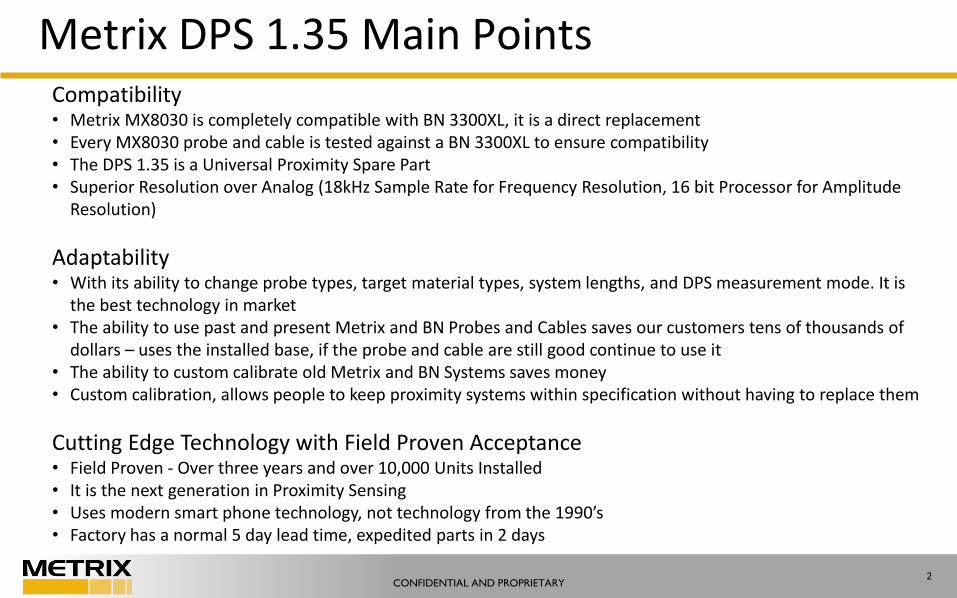
Metrix DPS 1.35 Main PointsCompatibility• Metrix MX8030 is completely compatible with BN 3300XL, it is a direct replacement• Every MX8030 probe and cable is tested against a BN 3300XL to ensure compatibility• The DPS 1.35 is a Universal Proximity Spare Part• Superior Resolution over Analog (18kHz Sample Rate for Frequency Resolution, 16 bit Processor for Amplitude
Resolution)
Adaptability• With its ability to change probe types, target material types, system lengths, and DPS measurement mode. It is
the best technology in market• The ability to use past and present Metrix and BN Probes and Cables saves our customers tens of thousands of
dollars – uses the installed base, if the probe and cable are still good continue to use it• The ability to custom calibrate old Metrix and BN Systems saves money• Custom calibration, allows people to keep proximity systems within specification without having to replace them
Cutting Edge Technology with Field Proven Acceptance• Field Proven - Over three years and over 10,000 Units Installed• It is the next generation in Proximity Sensing• Uses modern smart phone technology, not technology from the 1990’s• Factory has a normal 5 day lead time, expedited parts in 2 days
CONFIDENTIAL AND PROPRIETARY3
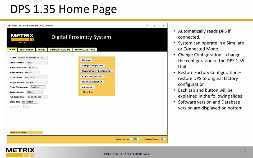
DPS 1.35 Home Page
• Automatically reads DPS if connected.
• System can operate in a Simulate or Connected Mode.
• Change Configuration – change the configuration of the DPS 1.35 Unit
• Restore Factory Configuration –restore DPS to original factory configuration
• Each tab and button will be explained in the following slides
• Software version and Database version are displayed on bottom
CONFIDENTIAL AND PROPRIETARY4
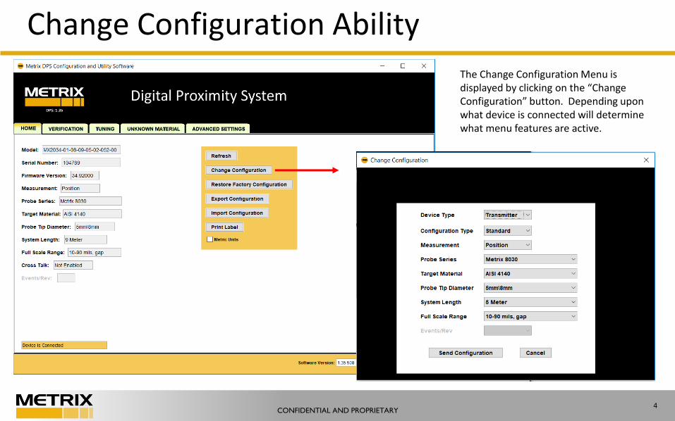
Change Configuration Ability
The Change Configuration Menu is displayed by clicking on the “Change Configuration” button. Depending upon what device is connected will determine what menu features are active.
CONFIDENTIAL AND PROPRIETARY5
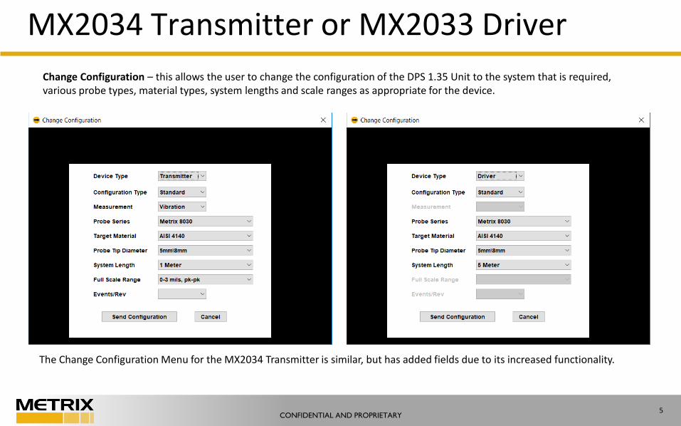
MX2034 Transmitter or MX2033 Driver
Change Configuration – this allows the user to change the configuration of the DPS 1.35 Unit to the system that is required, various probe types, material types, system lengths and scale ranges as appropriate for the device.
The Change Configuration Menu for the MX2034 Transmitter is similar, but has added fields due to its increased functionality.
CONFIDENTIAL AND PROPRIETARY6
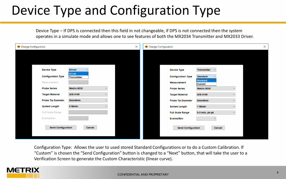
Device Type and Configuration TypeDevice Type – If DPS is connected then this field in not changeable, if DPS is not connected then the system operates in a simulate mode and allows one to see features of both the MX2034 Transmitter and MX2033 Driver.
Configuration Type: Allows the user to used stored Standard Configurations or to do a Custom Calibration. If “Custom” is chosen the “Send Configuration” button is changed to a “Next” button, that will take the user to a Verification Screen to generate the Custom Characteristic (linear curve).
CONFIDENTIAL AND PROPRIETARY7
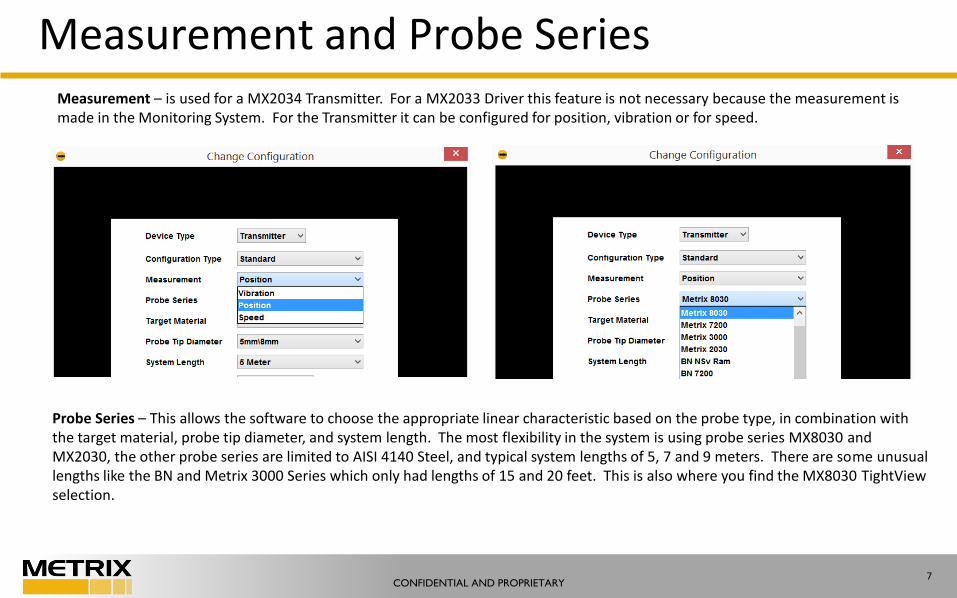
Measurement and Probe SeriesMeasurement – is used for a MX2034 Transmitter. For a MX2033 Driver this feature is not necessary because the measurement is made in the Monitoring System. For the Transmitter it can be configured for position, vibration or for speed.
Probe Series – This allows the software to choose the appropriate linear characteristic based on the probe type, in combination with the target material, probe tip diameter, and system length. The most flexibility in the system is using probe series MX8030 andMX2030, the other probe series are limited to AISI 4140 Steel, and typical system lengths of 5, 7 and 9 meters. There are some unusual lengths like the BN and Metrix 3000 Series which only had lengths of 15 and 20 feet. This is also where you find the MX8030 TightViewselection.
CONFIDENTIAL AND PROPRIETARY8
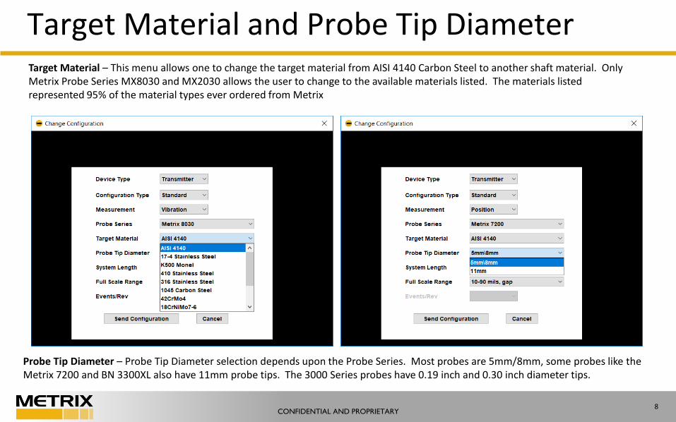
Target Material and Probe Tip DiameterTarget Material – This menu allows one to change the target material from AISI 4140 Carbon Steel to another shaft material. Only Metrix Probe Series MX8030 and MX2030 allows the user to change to the available materials listed. The materials listed represented 95% of the material types ever ordered from Metrix
Probe Tip Diameter – Probe Tip Diameter selection depends upon the Probe Series. Most probes are 5mm/8mm, some probes like the Metrix 7200 and BN 3300XL also have 11mm probe tips. The 3000 Series probes have 0.19 inch and 0.30 inch diameter tips.
CONFIDENTIAL AND PROPRIETARY9
System Length
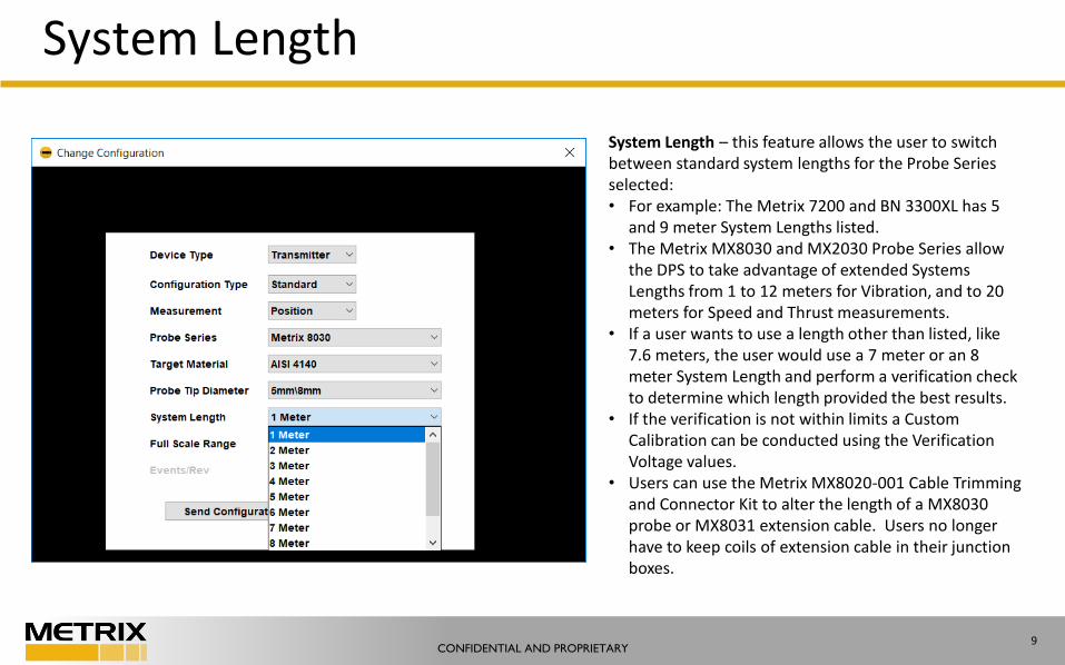
System Length – this feature allows the user to switch between standard system lengths for the Probe Series selected:• For example: The Metrix 7200 and BN 3300XL has 5
and 9 meter System Lengths listed. • The Metrix MX8030 and MX2030 Probe Series allow
the DPS to take advantage of extended Systems Lengths from 1 to 12 meters for Vibration, and to 20 meters for Speed and Thrust measurements.
• If a user wants to use a length other than listed, like 7.6 meters, the user would use a 7 meter or an 8 meter System Length and perform a verification check to determine which length provided the best results.
• If the verification is not within limits a Custom Calibration can be conducted using the Verification Voltage values.
• Users can use the Metrix MX8020-001 Cable Trimming and Connector Kit to alter the length of a MX8030 probe or MX8031 extension cable. Users no longer have to keep coils of extension cable in their junction boxes.
CONFIDENTIAL AND PROPRIETARY10
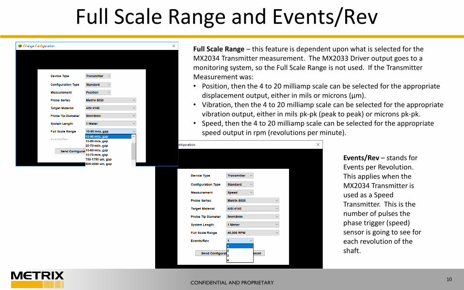
Full Scale Range and Events/RevFull Scale Range – this feature is dependent upon what is selected for the MX2034 Transmitter measurement. The MX2033 Driver output goes to a monitoring system, so the Full Scale Range is not used. If the Transmitter Measurement was:• Position, then the 4 to 20 milliamp scale can be selected for the appropriate
displacement output, either in mils or microns (µm). • Vibration, then the 4 to 20 milliamp scale can be selected for the appropriate
vibration output, either in mils pk-pk (peak to peak) or microns pk-pk. • Speed, then the 4 to 20 milliamp scale can be selected for the appropriate
speed output in rpm (revolutions per minute).
Events/Rev – stands for Events per Revolution. This applies when the MX2034 Transmitter is used as a Speed Transmitter. This is the number of pulses the phase trigger (speed) sensor is going to see for each revolution of the shaft.
CONFIDENTIAL AND PROPRIETARY11
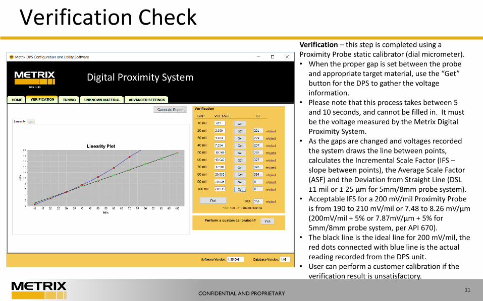
Verification CheckVerification – this step is completed using a Proximity Probe static calibrator (dial micrometer). • When the proper gap is set between the probe
and appropriate target material, use the “Get” button for the DPS to gather the voltage information.
• Please note that this process takes between 5 and 10 seconds, and cannot be filled in. It must be the voltage measured by the Metrix Digital Proximity System.
• As the gaps are changed and voltages recorded the system draws the line between points, calculates the Incremental Scale Factor (IFS –slope between points), the Average Scale Factor (ASF) and the Deviation from Straight Line (DSL ±1 mil or ± 25 µm for 5mm/8mm probe system).
• Acceptable IFS for a 200 mV/mil Proximity Probe is from 190 to 210 mV/mil or 7.48 to 8.26 mV/µm (200mV/mil + 5% or 7.87mV/µm + 5% for 5mm/8mm probe system, per API 670).
• The black line is the ideal line for 200 mV/mil, the red dots connected with blue line is the actual reading recorded from the DPS unit.
• User can perform a customer calibration if the verification result is unsatisfactory.
CONFIDENTIAL AND PROPRIETARY12
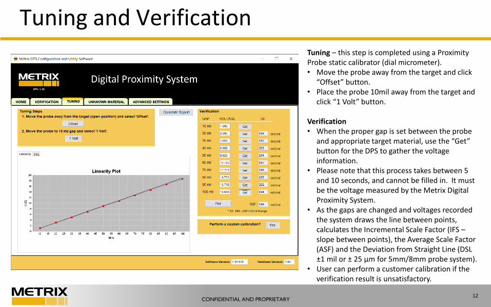
Tuning and VerificationTuning – this step is completed using a Proximity Probe static calibrator (dial micrometer). • Move the probe away from the target and click
“Offset” button. • Place the probe 10mil away from the target and
click “1 Volt” button.
Verification• When the proper gap is set between the probe
and appropriate target material, use the “Get” button for the DPS to gather the voltage information.
• Please note that this process takes between 5 and 10 seconds, and cannot be filled in. It must be the voltage measured by the Metrix Digital Proximity System.
• As the gaps are changed and voltages recorded the system draws the line between points, calculates the Incremental Scale Factor (IFS –slope between points), the Average Scale Factor (ASF) and the Deviation from Straight Line (DSL ±1 mil or ± 25 µm for 5mm/8mm probe system).
• User can perform a customer calibration if the verification result is unsatisfactory.
CONFIDENTIAL AND PROPRIETARY13
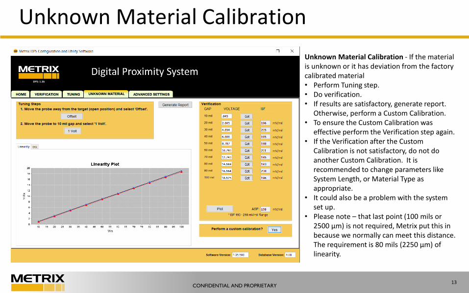
Unknown Material Calibration
Unknown Material Calibration - If the material is unknown or it has deviation from the factory calibrated material• Perform Tuning step.• Do verification. • If results are satisfactory, generate report.
Otherwise, perform a Custom Calibration.• To ensure the Custom Calibration was
effective perform the Verification step again. • If the Verification after the Custom
Calibration is not satisfactory, do not do another Custom Calibration. It is recommended to change parameters like System Length, or Material Type as appropriate.
• It could also be a problem with the system set up.
• Please note – that last point (100 mils or 2500 µm) is not required, Metrix put this in because we normally can meet this distance. The requirement is 80 mils (2250 µm) of linearity.
CONFIDENTIAL AND PROPRIETARY14
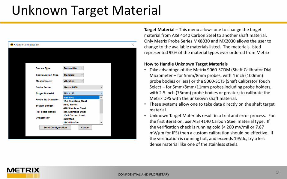
Unknown Target Material Target Material – This menu allows one to change the target material from AISI 4140 Carbon Steel to another shaft material. Only Metrix Probe Series MX8030 and MX2030 allows the user to change to the available materials listed. The materials listed represented 95% of the material types ever ordered from Metrix
How to Handle Unknown Target Materials• Take advantage of the Metrix 9060-SCDM (Shaft Calibrator Dial
Micrometer – for 5mm/8mm probes, with 4 inch (100mm) probe bodies or less) or the 9060-SCTS (Shaft Calibrator Touch Select – for 5mm/8mm/11mm probes including probe holders, with 2.5 inch (75mm) probe bodies or greater) to calibrate the Metrix DPS with the unknown shaft material.
• These systems allow one to take data directly on the shaft target material.
• Unknown Target Materials result in a trial and error process. For the first iteration, use AISI 4140 Carbon Steel material type. If the verification check is running cold (< 200 mV/mil or 7.87 mV/µm for IFS) then a custom calibration should be effective. If the verification is running hot, and exceeds 19Vdc, try a less dense material like one of the stainless steels.
CONFIDENTIAL AND PROPRIETARY15
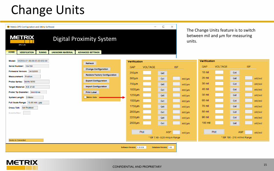
Change Units
The Change Units feature is to switch between mil and µm for measuring units.
CONFIDENTIAL AND PROPRIETARY16
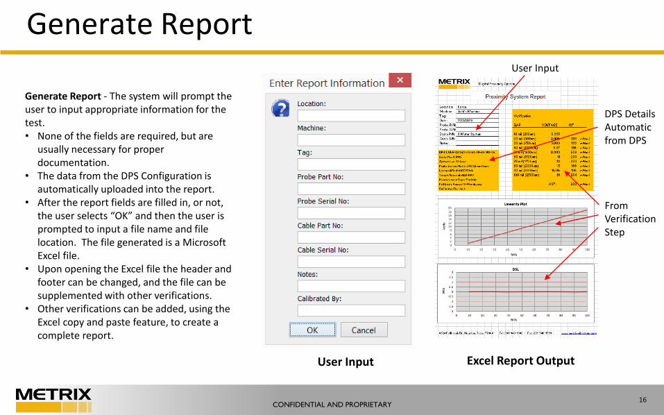
Generate Report
Generate Report - The system will prompt the user to input appropriate information for the test. • None of the fields are required, but are
usually necessary for proper documentation.
• The data from the DPS Configuration is automatically uploaded into the report.
• After the report fields are filled in, or not, the user selects “OK” and then the user is prompted to input a file name and file location. The file generated is a Microsoft Excel file.
• Upon opening the Excel file the header and footer can be changed, and the file can be supplemented with other verifications.
• Other verifications can be added, using the Excel copy and paste feature, to create a complete report.
User Input Excel Report Output
From Verification Step
DPS DetailsAutomatic from DPS
User Input
CONFIDENTIAL AND PROPRIETARY17
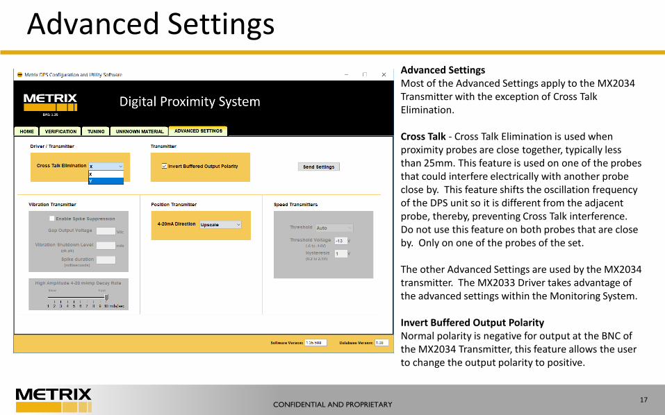
Advanced SettingsAdvanced SettingsMost of the Advanced Settings apply to the MX2034 Transmitter with the exception of Cross Talk Elimination.
Cross Talk - Cross Talk Elimination is used when proximity probes are close together, typically less than 25mm. This feature is used on one of the probes that could interfere electrically with another probe close by. This feature shifts the oscillation frequency of the DPS unit so it is different from the adjacent probe, thereby, preventing Cross Talk interference. Do not use this feature on both probes that are close by. Only on one of the probes of the set.
The other Advanced Settings are used by the MX2034 transmitter. The MX2033 Driver takes advantage of the advanced settings within the Monitoring System.
Invert Buffered Output PolarityNormal polarity is negative for output at the BNC of the MX2034 Transmitter, this feature allows the user to change the output polarity to positive.
CONFIDENTIAL AND PROPRIETARY18
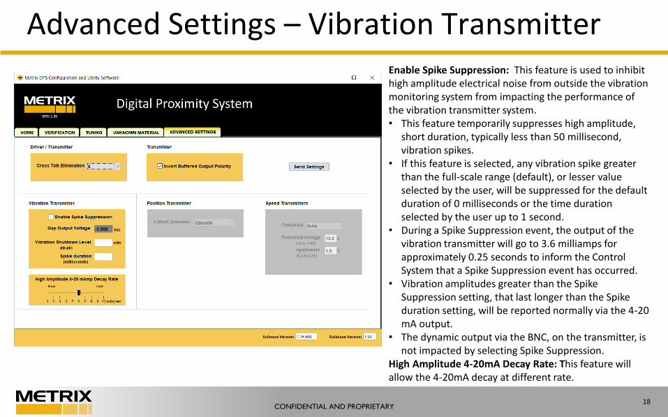
Advanced Settings – Vibration TransmitterEnable Spike Suppression: This feature is used to inhibit high amplitude electrical noise from outside the vibration monitoring system from impacting the performance of the vibration transmitter system. • This feature temporarily suppresses high amplitude,
short duration, typically less than 50 millisecond, vibration spikes.
• If this feature is selected, any vibration spike greater than the full-scale range (default), or lesser value selected by the user, will be suppressed for the default duration of 0 milliseconds or the time duration selected by the user up to 1 second.
• During a Spike Suppression event, the output of the vibration transmitter will go to 3.6 milliamps for approximately 0.25 seconds to inform the Control System that a Spike Suppression event has occurred.
• Vibration amplitudes greater than the Spike Suppression setting, that last longer than the Spike duration setting, will be reported normally via the 4-20 mA output.
• The dynamic output via the BNC, on the transmitter, is not impacted by selecting Spike Suppression.
High Amplitude 4-20mA Decay Rate: This feature will allow the 4-20mA decay at different rate.
CONFIDENTIAL AND PROPRIETARY19
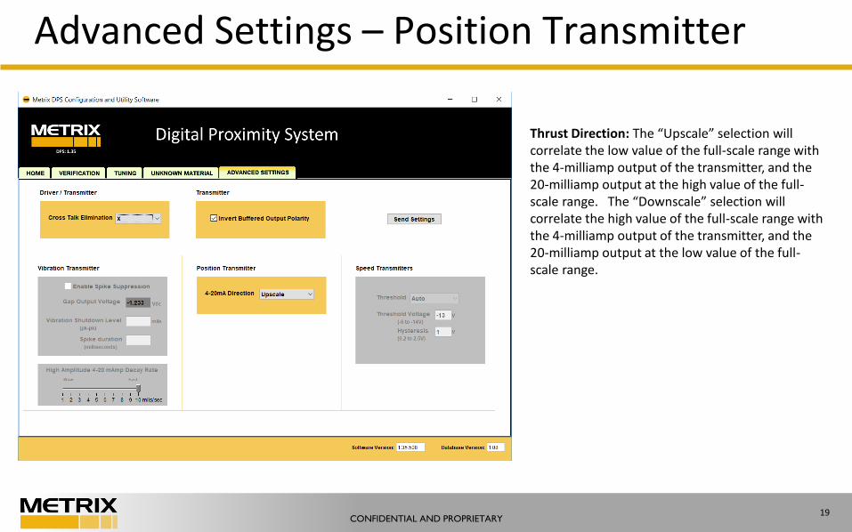
Advanced Settings – Position Transmitter
Thrust Direction: The “Upscale” selection will correlate the low value of the full-scale range with the 4-milliamp output of the transmitter, and the 20-milliamp output at the high value of the full-scale range. The “Downscale” selection will correlate the high value of the full-scale range with the 4-milliamp output of the transmitter, and the 20-milliamp output at the low value of the full-scale range.
CONFIDENTIAL AND PROPRIETARY20
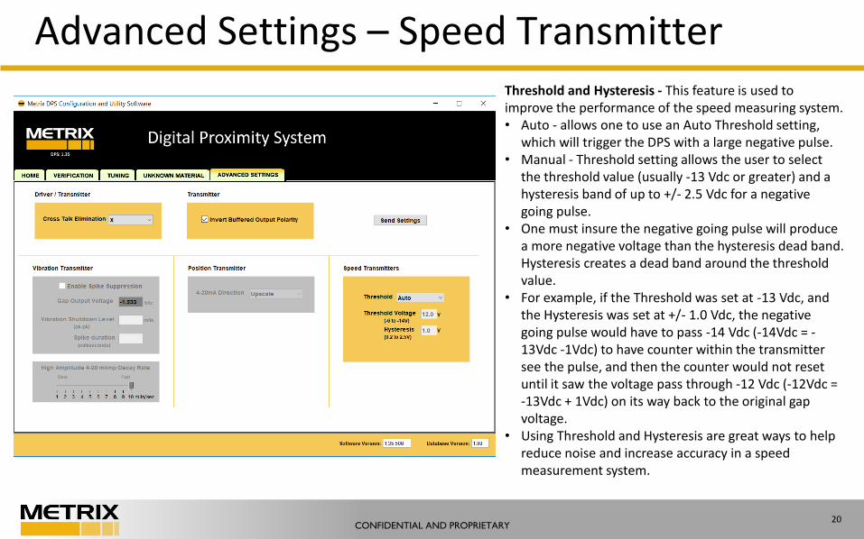
Advanced Settings – Speed TransmitterThreshold and Hysteresis - This feature is used to improve the performance of the speed measuring system. • Auto - allows one to use an Auto Threshold setting,
which will trigger the DPS with a large negative pulse.• Manual - Threshold setting allows the user to select
the threshold value (usually -13 Vdc or greater) and a hysteresis band of up to +/- 2.5 Vdc for a negative going pulse.
• One must insure the negative going pulse will produce a more negative voltage than the hysteresis dead band. Hysteresis creates a dead band around the threshold value.
• For example, if the Threshold was set at -13 Vdc, and the Hysteresis was set at +/- 1.0 Vdc, the negative going pulse would have to pass -14 Vdc (-14Vdc = -13Vdc -1Vdc) to have counter within the transmitter see the pulse, and then the counter would not reset until it saw the voltage pass through -12 Vdc (-12Vdc = -13Vdc + 1Vdc) on its way back to the original gap voltage.
• Using Threshold and Hysteresis are great ways to help reduce noise and increase accuracy in a speed measurement system.

CONFIDENTIAL AND PROPRIETARY 21
Thank you.