Embed Size (px)
Citation preview

x
DPO2000 and MSO2000 SeriesOscilloscopesZZZ
User Manual
*P071231902*
071-2319-02

DPO2000 and MSO2000 SeriesOscilloscopesZZZ
User Manual
xx
www.tektronix.com071-2319-02
Copyright © Tektronix. All rights reserved. Licensed software products are owned by Tektronix or its subsidiaries or suppliers, and areprotected by national copyright laws and international treaty provisions.
Tektronix products are covered by U.S. and foreign patents, issued and pending. Information in this publication supersedes that in allpreviously published material. Specifications and price change privileges reserved.
TEKTRONIX and TEK are registered trademarks of Tektronix, Inc.
e*Scope, FilterVu, OpenChoice, TekSecure, and TekVPI and Wave Inspector are registered trademarks of Tektronix, Inc.
PictBridge is a registered trademark of the Standard of Camera & Imaging Products Association CIPA DC-001-2003 Digital PhotoSolutions for Imaging Devices.
Contacting TektronixTektronix, Inc.14200 SW Karl Braun DriveP.O. Box 500Beaverton, OR 97077USA
For product information, sales, service, and technical support:In North America, call 1-800-833-9200.Worldwide, visit www.tektronix.com to find contacts in your area.

MSO2000 and DPO2000 Series Oscilloscopes
WarrantyTektronix warrants that the product will be free from defects in materials and workmanship for a period of three (3) years from the dateof original purchase from an authorized Tektronix distributor. If the product proves defective during this warranty period, Tektronix, at itsoption, either will repair the defective product without charge for parts and labor, or will provide a replacement in exchange for thedefective product. Batteries are excluded from this warranty. Parts, modules and replacement products used by Tektronix for warrantywork may be new or reconditioned to like new performance. All replaced parts, modules and products become the property of Tektronix.
In order to obtain service under this warranty, Customer must notify Tektronix of the defect before the expiration of the warrantyperiod and make suitable arrangements for the performance of service. Customer shall be responsible for packaging and shippingthe defective product to the service center designated by Tektronix, shipping charges prepaid, and with a copy of customer proof ofpurchase. Tektronix shall pay for the return of the product to Customer if the shipment is to a location within the country in whichthe Tektronix service center is located. Customer shall be responsible for paying all shipping charges, duties, taxes, and any othercharges for products returned to any other locations.
This warranty shall not apply to any defect, failure or damage caused by improper use or improper or inadequate maintenance andcare. Tektronix shall not be obligated to furnish service under this warranty a) to repair damage resulting from attempts by personnelother than Tektronix representatives to install, repair or service the product; b) to repair damage resulting from improper use orconnection to incompatible equipment; c) to repair any damage or malfunction caused by the use of non-Tektronix supplies; ord) to service a product that has been modified or integrated with other products when the effect of such modification or integrationincreases the time or difficulty of servicing the product.
THIS WARRANTY IS GIVEN BY TEKTRONIX WITH RESPECT TO THE PRODUCT IN LIEU OF ANY OTHER WARRANTIES,EXPRESS OR IMPLIED. TEKTRONIX AND ITS VENDORS DISCLAIM ANY IMPLIED WARRANTIES OF MERCHANTABILITY ORFITNESS FOR A PARTICULAR PURPOSE. TEKTRONIX’ RESPONSIBILITY TO REPAIR OR REPLACE DEFECTIVE PRODUCTSIS THE SOLE AND EXCLUSIVE REMEDY PROVIDED TO THE CUSTOMER FOR BREACH OF THIS WARRANTY. TEKTRONIXAND ITS VENDORS WILL NOT BE LIABLE FOR ANY INDIRECT, SPECIAL, INCIDENTAL, OR CONSEQUENTIAL DAMAGESIRRESPECTIVE OF WHETHER TEKTRONIX OR THE VENDOR HAS ADVANCE NOTICE OF THE POSSIBILITY OF SUCHDAMAGES.
[W16 – 15AUG04]

P2221 Probe
WarrantyTektronix warrants that this product will be free from defects in materials and workmanship for a period of one (1) year from the date ofshipment. If any such product proves defective during this warranty period, Tektronix, at its option, either will repair the defectiveproduct without charge for parts and labor, or will provide a replacement in exchange for the defective product. Parts, modules andreplacement products used by Tektronix for warranty work may be new or reconditioned to like new performance. All replacedparts, modules and products become the property of Tektronix.
In order to obtain service under this warranty, Customer must notify Tektronix of the defect before the expiration of the warranty periodand make suitable arrangements for the performance of service. Customer shall be responsible for packaging and shipping thedefective product to the service center designated by Tektronix, with shipping charges prepaid. Tektronix shall pay for the return of theproduct to Customer if the shipment is to a location within the country in which the Tektronix service center is located. Customer shallbe responsible for paying all shipping charges, duties, taxes, and any other charges for products returned to any other locations.
This warranty shall not apply to any defect, failure or damage caused by improper use or improper or inadequate maintenance andcare. Tektronix shall not be obligated to furnish service under this warranty a) to repair damage resulting from attempts by personnelother than Tektronix representatives to install, repair or service the product; b) to repair damage resulting from improper use orconnection to incompatible equipment; c) to repair any damage or malfunction caused by the use of non-Tektronix supplies; ord) to service a product that has been modified or integrated with other products when the effect of such modification or integrationincreases the time or difficulty of servicing the product.
THIS WARRANTY IS GIVEN BY TEKTRONIX WITH RESPECT TO THE PRODUCT IN LIEU OF ANY OTHER WARRANTIES,EXPRESS OR IMPLIED. TEKTRONIX AND ITS VENDORS DISCLAIM ANY IMPLIED WARRANTIES OF MERCHANTABILITY ORFITNESS FOR A PARTICULAR PURPOSE. TEKTRONIX’ RESPONSIBILITY TO REPAIR OR REPLACE DEFECTIVE PRODUCTSIS THE SOLE AND EXCLUSIVE REMEDY PROVIDED TO THE CUSTOMER FOR BREACH OF THIS WARRANTY. TEKTRONIXAND ITS VENDORS WILL NOT BE LIABLE FOR ANY INDIRECT, SPECIAL, INCIDENTAL, OR CONSEQUENTIAL DAMAGESIRRESPECTIVE OF WHETHER TEKTRONIX OR THE VENDOR HAS ADVANCE NOTICE OF THE POSSIBILITY OF SUCHDAMAGES.
[W2 – 15AUG04]
P6316 Probe
WarrantyTektronix warrants that the product will be free from defects in materials and workmanship for a period of one (1) year from the date oforiginal purchase from an authorized Tektronix distributor. If the product proves defective during this warranty period, Tektronix, at itsoption, either will repair the defective product without charge for parts and labor, or will provide a replacement in exchange for thedefective product. Batteries are excluded from this warranty. Parts, modules and replacement products used by Tektronix for warrantywork may be new or reconditioned to like new performance. All replaced parts, modules and products become the property of Tektronix.
In order to obtain service under this warranty, Customer must notify Tektronix of the defect before the expiration of the warrantyperiod and make suitable arrangements for the performance of service. Customer shall be responsible for packaging and shippingthe defective product to the service center designated by Tektronix, shipping charges prepaid, and with a copy of customer proof ofpurchase. Tektronix shall pay for the return of the product to Customer if the shipment is to a location within the country in whichthe Tektronix service center is located. Customer shall be responsible for paying all shipping charges, duties, taxes, and any othercharges for products returned to any other locations.
This warranty shall not apply to any defect, failure or damage caused by improper use or improper or inadequate maintenance andcare. Tektronix shall not be obligated to furnish service under this warranty a) to repair damage resulting from attempts by personnelother than Tektronix representatives to install, repair or service the product; b) to repair damage resulting from improper use orconnection to incompatible equipment; c) to repair any damage or malfunction caused by the use of non-Tektronix supplies; ord) to service a product that has been modified or integrated with other products when the effect of such modification or integrationincreases the time or difficulty of servicing the product.
THIS WARRANTY IS GIVEN BY TEKTRONIX WITH RESPECT TO THE PRODUCT IN LIEU OF ANY OTHER WARRANTIES,EXPRESS OR IMPLIED. TEKTRONIX AND ITS VENDORS DISCLAIM ANY IMPLIED WARRANTIES OF MERCHANTABILITY ORFITNESS FOR A PARTICULAR PURPOSE. TEKTRONIX’ RESPONSIBILITY TO REPAIR OR REPLACE DEFECTIVE PRODUCTSIS THE SOLE AND EXCLUSIVE REMEDY PROVIDED TO THE CUSTOMER FOR BREACH OF THIS WARRANTY. TEKTRONIXAND ITS VENDORS WILL NOT BE LIABLE FOR ANY INDIRECT, SPECIAL, INCIDENTAL, OR CONSEQUENTIAL DAMAGESIRRESPECTIVE OF WHETHER TEKTRONIX OR THE VENDOR HAS ADVANCE NOTICE OF THE POSSIBILITY OF SUCHDAMAGES.
[W15 – 15AUG04]

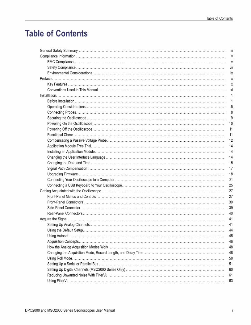
Table of Contents
Table of ContentsGeneral Safety Summary . . . . . . . . . . . . . . . . . . . . . . . . . . . . . . . . . . . . . . . . . . . . . . . . . . . . . . . . . . . . . . . . . . . . . . . . . . . . . . . . . . . . . . . . . . . . . . . . . . . . . . . . . . . . . iiiCompliance Information . . . . . . . . . . . . . . . . . . . . . . . . . . . . . . . . . . . . . . . . . . . . . . . . . . . . . . . . . . . . . . . . . . . . . . . . . . . . . . . . . . . . . . . . . . . . . . . . . . . . . . . . . . . . . . . v
EMC Compliance. . . . . . . . . . . . . . . . . . . . . . . . . . . . . . . . . . . . . . . . . . . . . . . . . . . . . . . . . . . . . . . . . . . . . . . . . . . . . . . . . . . . . . . . . . . . . . . . . . . . . . . . . . . . . . . . . vSafety Compliance . . . . . . . . . . . . . . . . . . . . . . . . . . . . . . . . . . . . . . . . . . . . . . . . . . . . . . . . . . . . . . . . . . . . . . . . . . . . . . . . . . . . . . . . . . . . . . . . . . . . . . . . . . . . . . viiEnvironmental Considerations. . . . . . . . . . . . . . . . . . . . . . . . . . . . . . . . . . . . . . . . . . . . . . . . . . . . . . . . . . . . . . . . . . . . . . . . . . . . . . . . . . . . . . . . . . . . . . . . . . . ix
Preface . . . . . . . . . . . . . . . . . . . . . . . . . . . . . . . . . . . . . . . . . . . . . . . . . . . . . . . . . . . . . . . . . . . . . . . . . . . . . . . . . . . . . . . . . . . . . . . . . . . . . . . . . . . . . . . . . . . . . . . . . . . . . . . . . xKey Features . . . . . . . . . . . . . . . . . . . . . . . . . . . . . . . . . . . . . . . . . . . . . . . . . . . . . . . . . . . . . . . . . . . . . . . . . . . . . . . . . . . . . . . . . . . . . . . . . . . . . . . . . . . . . . . . . . . . . xConventions Used in This Manual. . . . . . . . . . . . . . . . . . . . . . . . . . . . . . . . . . . . . . . . . . . . . . . . . . . . . . . . . . . . . . . . . . . . . . . . . . . . . . . . . . . . . . . . . . . . . . . xi
Installation. . . . . . . . . . . . . . . . . . . . . . . . . . . . . . . . . . . . . . . . . . . . . . . . . . . . . . . . . . . . . . . . . . . . . . . . . . . . . . . . . . . . . . . . . . . . . . . . . . . . . . . . . . . . . . . . . . . . . . . . . . . . . . 1Before Installation . . . . . . . . . . . . . . . . . . . . . . . . . . . . . . . . . . . . . . . . . . . . . . . . . . . . . . . . . . . . . . . . . . . . . . . . . . . . . . . . . . . . . . . . . . . . . . . . . . . . . . . . . . . . . . . . 1Operating Considerations. . . . . . . . . . . . . . . . . . . . . . . . . . . . . . . . . . . . . . . . . . . . . . . . . . . . . . . . . . . . . . . . . . . . . . . . . . . . . . . . . . . . . . . . . . . . . . . . . . . . . . . . 5Connecting Probes. . . . . . . . . . . . . . . . . . . . . . . . . . . . . . . . . . . . . . . . . . . . . . . . . . . . . . . . . . . . . . . . . . . . . . . . . . . . . . . . . . . . . . . . . . . . . . . . . . . . . . . . . . . . . . . 8Securing the Oscilloscope . . . . . . . . . . . . . . . . . . . . . . . . . . . . . . . . . . . . . . . . . . . . . . . . . . . . . . . . . . . . . . . . . . . . . . . . . . . . . . . . . . . . . . . . . . . . . . . . . . . . . . . 9Powering On the Oscilloscope . . . . . . . . . . . . . . . . . . . . . . . . . . . . . . . . . . . . . . . . . . . . . . . . . . . . . . . . . . . . . . . . . . . . . . . . . . . . . . . . . . . . . . . . . . . . . . . . . 10Powering Off the Oscilloscope. . . . . . . . . . . . . . . . . . . . . . . . . . . . . . . . . . . . . . . . . . . . . . . . . . . . . . . . . . . . . . . . . . . . . . . . . . . . . . . . . . . . . . . . . . . . . . . . . . 11Functional Check. . . . . . . . . . . . . . . . . . . . . . . . . . . . . . . . . . . . . . . . . . . . . . . . . . . . . . . . . . . . . . . . . . . . . . . . . . . . . . . . . . . . . . . . . . . . . . . . . . . . . . . . . . . . . . . . 11Compensating a Passive Voltage Probe . . . . . . . . . . . . . . . . . . . . . . . . . . . . . . . . . . . . . . . . . . . . . . . . . . . . . . . . . . . . . . . . . . . . . . . . . . . . . . . . . . . . . . . 12Application Module Free Trial. . . . . . . . . . . . . . . . . . . . . . . . . . . . . . . . . . . . . . . . . . . . . . . . . . . . . . . . . . . . . . . . . . . . . . . . . . . . . . . . . . . . . . . . . . . . . . . . . . . 14Installing an Application Module . . . . . . . . . . . . . . . . . . . . . . . . . . . . . . . . . . . . . . . . . . . . . . . . . . . . . . . . . . . . . . . . . . . . . . . . . . . . . . . . . . . . . . . . . . . . . . . . 14Changing the User Interface Language . . . . . . . . . . . . . . . . . . . . . . . . . . . . . . . . . . . . . . . . . . . . . . . . . . . . . . . . . . . . . . . . . . . . . . . . . . . . . . . . . . . . . . . . 14Changing the Date and Time . . . . . . . . . . . . . . . . . . . . . . . . . . . . . . . . . . . . . . . . . . . . . . . . . . . . . . . . . . . . . . . . . . . . . . . . . . . . . . . . . . . . . . . . . . . . . . . . . . . 15Signal Path Compensation . . . . . . . . . . . . . . . . . . . . . . . . . . . . . . . . . . . . . . . . . . . . . . . . . . . . . . . . . . . . . . . . . . . . . . . . . . . . . . . . . . . . . . . . . . . . . . . . . . . . . 17Upgrading Firmware . . . . . . . . . . . . . . . . . . . . . . . . . . . . . . . . . . . . . . . . . . . . . . . . . . . . . . . . . . . . . . . . . . . . . . . . . . . . . . . . . . . . . . . . . . . . . . . . . . . . . . . . . . . . 18Connecting Your Oscilloscope to a Computer . . . . . . . . . . . . . . . . . . . . . . . . . . . . . . . . . . . . . . . . . . . . . . . . . . . . . . . . . . . . . . . . . . . . . . . . . . . . . . . . . 21Connecting a USB Keyboard to Your Oscilloscope. . . . . . . . . . . . . . . . . . . . . . . . . . . . . . . . . . . . . . . . . . . . . . . . . . . . . . . . . . . . . . . . . . . . . . . . . . . . 25
Getting Acquainted with the Oscilloscope . . . . . . . . . . . . . . . . . . . . . . . . . . . . . . . . . . . . . . . . . . . . . . . . . . . . . . . . . . . . . . . . . . . . . . . . . . . . . . . . . . . . . . . . . . . 27Front-Panel Menus and Controls . . . . . . . . . . . . . . . . . . . . . . . . . . . . . . . . . . . . . . . . . . . . . . . . . . . . . . . . . . . . . . . . . . . . . . . . . . . . . . . . . . . . . . . . . . . . . . . 27Front-Panel Connectors . . . . . . . . . . . . . . . . . . . . . . . . . . . . . . . . . . . . . . . . . . . . . . . . . . . . . . . . . . . . . . . . . . . . . . . . . . . . . . . . . . . . . . . . . . . . . . . . . . . . . . . . 39Side-Panel Connector. . . . . . . . . . . . . . . . . . . . . . . . . . . . . . . . . . . . . . . . . . . . . . . . . . . . . . . . . . . . . . . . . . . . . . . . . . . . . . . . . . . . . . . . . . . . . . . . . . . . . . . . . . . 39Rear-Panel Connectors . . . . . . . . . . . . . . . . . . . . . . . . . . . . . . . . . . . . . . . . . . . . . . . . . . . . . . . . . . . . . . . . . . . . . . . . . . . . . . . . . . . . . . . . . . . . . . . . . . . . . . . . . 40
Acquire the Signal . . . . . . . . . . . . . . . . . . . . . . . . . . . . . . . . . . . . . . . . . . . . . . . . . . . . . . . . . . . . . . . . . . . . . . . . . . . . . . . . . . . . . . . . . . . . . . . . . . . . . . . . . . . . . . . . . . . . 41Setting Up Analog Channels. . . . . . . . . . . . . . . . . . . . . . . . . . . . . . . . . . . . . . . . . . . . . . . . . . . . . . . . . . . . . . . . . . . . . . . . . . . . . . . . . . . . . . . . . . . . . . . . . . . . 41Using the Default Setup. . . . . . . . . . . . . . . . . . . . . . . . . . . . . . . . . . . . . . . . . . . . . . . . . . . . . . . . . . . . . . . . . . . . . . . . . . . . . . . . . . . . . . . . . . . . . . . . . . . . . . . . . 44Using Autoset . . . . . . . . . . . . . . . . . . . . . . . . . . . . . . . . . . . . . . . . . . . . . . . . . . . . . . . . . . . . . . . . . . . . . . . . . . . . . . . . . . . . . . . . . . . . . . . . . . . . . . . . . . . . . . . . . . . 45Acquisition Concepts. . . . . . . . . . . . . . . . . . . . . . . . . . . . . . . . . . . . . . . . . . . . . . . . . . . . . . . . . . . . . . . . . . . . . . . . . . . . . . . . . . . . . . . . . . . . . . . . . . . . . . . . . . . . 46How the Analog Acquisition Modes Work . . . . . . . . . . . . . . . . . . . . . . . . . . . . . . . . . . . . . . . . . . . . . . . . . . . . . . . . . . . . . . . . . . . . . . . . . . . . . . . . . . . . . . 48Changing the Acquisition Mode, Record Length, and Delay Time. . . . . . . . . . . . . . . . . . . . . . . . . . . . . . . . . . . . . . . . . . . . . . . . . . . . . . . . . . . . 48Using Roll Mode. . . . . . . . . . . . . . . . . . . . . . . . . . . . . . . . . . . . . . . . . . . . . . . . . . . . . . . . . . . . . . . . . . . . . . . . . . . . . . . . . . . . . . . . . . . . . . . . . . . . . . . . . . . . . . . . . 50Setting Up a Serial or Parallel Bus . . . . . . . . . . . . . . . . . . . . . . . . . . . . . . . . . . . . . . . . . . . . . . . . . . . . . . . . . . . . . . . . . . . . . . . . . . . . . . . . . . . . . . . . . . . . . 51Setting Up Digital Channels (MSO2000 Series Only) . . . . . . . . . . . . . . . . . . . . . . . . . . . . . . . . . . . . . . . . . . . . . . . . . . . . . . . . . . . . . . . . . . . . . . . . . 60Reducing Unwanted Noise With FilterVu . . . . . . . . . . . . . . . . . . . . . . . . . . . . . . . . . . . . . . . . . . . . . . . . . . . . . . . . . . . . . . . . . . . . . . . . . . . . . . . . . . . . . . 61Using FilterVu . . . . . . . . . . . . . . . . . . . . . . . . . . . . . . . . . . . . . . . . . . . . . . . . . . . . . . . . . . . . . . . . . . . . . . . . . . . . . . . . . . . . . . . . . . . . . . . . . . . . . . . . . . . . . . . . . . . 63
DPO2000 and MSO2000 Series Oscilloscopes User Manual i

Table of Contents
Trigger Setup . . . . . . . . . . . . . . . . . . . . . . . . . . . . . . . . . . . . . . . . . . . . . . . . . . . . . . . . . . . . . . . . . . . . . . . . . . . . . . . . . . . . . . . . . . . . . . . . . . . . . . . . . . . . . . . . . . . . . . . . . 65Triggering Concepts. . . . . . . . . . . . . . . . . . . . . . . . . . . . . . . . . . . . . . . . . . . . . . . . . . . . . . . . . . . . . . . . . . . . . . . . . . . . . . . . . . . . . . . . . . . . . . . . . . . . . . . . . . . . . 65Choosing a Trigger Type. . . . . . . . . . . . . . . . . . . . . . . . . . . . . . . . . . . . . . . . . . . . . . . . . . . . . . . . . . . . . . . . . . . . . . . . . . . . . . . . . . . . . . . . . . . . . . . . . . . . . . . . 68Selecting Triggers . . . . . . . . . . . . . . . . . . . . . . . . . . . . . . . . . . . . . . . . . . . . . . . . . . . . . . . . . . . . . . . . . . . . . . . . . . . . . . . . . . . . . . . . . . . . . . . . . . . . . . . . . . . . . . . 68Triggering on Buses. . . . . . . . . . . . . . . . . . . . . . . . . . . . . . . . . . . . . . . . . . . . . . . . . . . . . . . . . . . . . . . . . . . . . . . . . . . . . . . . . . . . . . . . . . . . . . . . . . . . . . . . . . . . . 70Checking Trigger Settings . . . . . . . . . . . . . . . . . . . . . . . . . . . . . . . . . . . . . . . . . . . . . . . . . . . . . . . . . . . . . . . . . . . . . . . . . . . . . . . . . . . . . . . . . . . . . . . . . . . . . . 74Starting and Stopping an Acquisition. . . . . . . . . . . . . . . . . . . . . . . . . . . . . . . . . . . . . . . . . . . . . . . . . . . . . . . . . . . . . . . . . . . . . . . . . . . . . . . . . . . . . . . . . . . 75
Display Waveform Data . . . . . . . . . . . . . . . . . . . . . . . . . . . . . . . . . . . . . . . . . . . . . . . . . . . . . . . . . . . . . . . . . . . . . . . . . . . . . . . . . . . . . . . . . . . . . . . . . . . . . . . . . . . . . . 76Adding and Removing a Waveform . . . . . . . . . . . . . . . . . . . . . . . . . . . . . . . . . . . . . . . . . . . . . . . . . . . . . . . . . . . . . . . . . . . . . . . . . . . . . . . . . . . . . . . . . . . . 76Setting the Display Style and Persistence . . . . . . . . . . . . . . . . . . . . . . . . . . . . . . . . . . . . . . . . . . . . . . . . . . . . . . . . . . . . . . . . . . . . . . . . . . . . . . . . . . . . . 76Setting Waveform Intensity . . . . . . . . . . . . . . . . . . . . . . . . . . . . . . . . . . . . . . . . . . . . . . . . . . . . . . . . . . . . . . . . . . . . . . . . . . . . . . . . . . . . . . . . . . . . . . . . . . . . . 79Scaling and Positioning a Waveform . . . . . . . . . . . . . . . . . . . . . . . . . . . . . . . . . . . . . . . . . . . . . . . . . . . . . . . . . . . . . . . . . . . . . . . . . . . . . . . . . . . . . . . . . . . 80Setting Input Parameters . . . . . . . . . . . . . . . . . . . . . . . . . . . . . . . . . . . . . . . . . . . . . . . . . . . . . . . . . . . . . . . . . . . . . . . . . . . . . . . . . . . . . . . . . . . . . . . . . . . . . . . 81Positioning and Labeling Bus Signals . . . . . . . . . . . . . . . . . . . . . . . . . . . . . . . . . . . . . . . . . . . . . . . . . . . . . . . . . . . . . . . . . . . . . . . . . . . . . . . . . . . . . . . . . . 83Positioning, Scaling, and Grouping Digital Channels. . . . . . . . . . . . . . . . . . . . . . . . . . . . . . . . . . . . . . . . . . . . . . . . . . . . . . . . . . . . . . . . . . . . . . . . . . 83Viewing Digital Channels . . . . . . . . . . . . . . . . . . . . . . . . . . . . . . . . . . . . . . . . . . . . . . . . . . . . . . . . . . . . . . . . . . . . . . . . . . . . . . . . . . . . . . . . . . . . . . . . . . . . . . . 85Annotating the Screen . . . . . . . . . . . . . . . . . . . . . . . . . . . . . . . . . . . . . . . . . . . . . . . . . . . . . . . . . . . . . . . . . . . . . . . . . . . . . . . . . . . . . . . . . . . . . . . . . . . . . . . . . . 86
Analyze Waveform Data. . . . . . . . . . . . . . . . . . . . . . . . . . . . . . . . . . . . . . . . . . . . . . . . . . . . . . . . . . . . . . . . . . . . . . . . . . . . . . . . . . . . . . . . . . . . . . . . . . . . . . . . . . . . . . 87Taking Automatic Measurements. . . . . . . . . . . . . . . . . . . . . . . . . . . . . . . . . . . . . . . . . . . . . . . . . . . . . . . . . . . . . . . . . . . . . . . . . . . . . . . . . . . . . . . . . . . . . . . 87Selecting Automatic Measurements. . . . . . . . . . . . . . . . . . . . . . . . . . . . . . . . . . . . . . . . . . . . . . . . . . . . . . . . . . . . . . . . . . . . . . . . . . . . . . . . . . . . . . . . . . . . 88Customizing an Automatic Measurement . . . . . . . . . . . . . . . . . . . . . . . . . . . . . . . . . . . . . . . . . . . . . . . . . . . . . . . . . . . . . . . . . . . . . . . . . . . . . . . . . . . . . . 91Taking Manual Measurements with Cursors . . . . . . . . . . . . . . . . . . . . . . . . . . . . . . . . . . . . . . . . . . . . . . . . . . . . . . . . . . . . . . . . . . . . . . . . . . . . . . . . . . . 94Using Math Waveforms . . . . . . . . . . . . . . . . . . . . . . . . . . . . . . . . . . . . . . . . . . . . . . . . . . . . . . . . . . . . . . . . . . . . . . . . . . . . . . . . . . . . . . . . . . . . . . . . . . . . . . . . . 97Using FFT . . . . . . . . . . . . . . . . . . . . . . . . . . . . . . . . . . . . . . . . . . . . . . . . . . . . . . . . . . . . . . . . . . . . . . . . . . . . . . . . . . . . . . . . . . . . . . . . . . . . . . . . . . . . . . . . . . . . . . . 98Using Reference Waveforms . . . . . . . . . . . . . . . . . . . . . . . . . . . . . . . . . . . . . . . . . . . . . . . . . . . . . . . . . . . . . . . . . . . . . . . . . . . . . . . . . . . . . . . . . . . . . . . . . 101Using Wave Inspector to Manage Long Record Length Waveforms. . . . . . . . . . . . . . . . . . . . . . . . . . . . . . . . . . . . . . . . . . . . . . . . . . . . . . . . 103
Save and Recall Information . . . . . . . . . . . . . . . . . . . . . . . . . . . . . . . . . . . . . . . . . . . . . . . . . . . . . . . . . . . . . . . . . . . . . . . . . . . . . . . . . . . . . . . . . . . . . . . . . . . . . . . 109Saving a Screen Image . . . . . . . . . . . . . . . . . . . . . . . . . . . . . . . . . . . . . . . . . . . . . . . . . . . . . . . . . . . . . . . . . . . . . . . . . . . . . . . . . . . . . . . . . . . . . . . . . . . . . . . . 111Saving and Recalling Waveform Data. . . . . . . . . . . . . . . . . . . . . . . . . . . . . . . . . . . . . . . . . . . . . . . . . . . . . . . . . . . . . . . . . . . . . . . . . . . . . . . . . . . . . . . . 112Saving and Recalling Setups . . . . . . . . . . . . . . . . . . . . . . . . . . . . . . . . . . . . . . . . . . . . . . . . . . . . . . . . . . . . . . . . . . . . . . . . . . . . . . . . . . . . . . . . . . . . . . . . . 114Saving with One Button Push . . . . . . . . . . . . . . . . . . . . . . . . . . . . . . . . . . . . . . . . . . . . . . . . . . . . . . . . . . . . . . . . . . . . . . . . . . . . . . . . . . . . . . . . . . . . . . . . 116Saving Setup, Screen Image, and Waveform Files. . . . . . . . . . . . . . . . . . . . . . . . . . . . . . . . . . . . . . . . . . . . . . . . . . . . . . . . . . . . . . . . . . . . . . . . . . 116Printing a Hard Copy. . . . . . . . . . . . . . . . . . . . . . . . . . . . . . . . . . . . . . . . . . . . . . . . . . . . . . . . . . . . . . . . . . . . . . . . . . . . . . . . . . . . . . . . . . . . . . . . . . . . . . . . . . 118Erasing Oscilloscope Memory . . . . . . . . . . . . . . . . . . . . . . . . . . . . . . . . . . . . . . . . . . . . . . . . . . . . . . . . . . . . . . . . . . . . . . . . . . . . . . . . . . . . . . . . . . . . . . . . 120
Using Application Modules . . . . . . . . . . . . . . . . . . . . . . . . . . . . . . . . . . . . . . . . . . . . . . . . . . . . . . . . . . . . . . . . . . . . . . . . . . . . . . . . . . . . . . . . . . . . . . . . . . . . . . . . . 122Appendix: Warranted Specifications, Safety Certifications, and Electromagnetic Compatibility . . . . . . . . . . . . . . . . . . . . . . . . . . . . . . . . 123Index
ii DPO2000 and MSO2000 Series Oscilloscopes User Manual

General Safety Summary
General Safety SummaryReview the following safety precautions to avoid injury and prevent damage to this product or any products connected to it.
To avoid potential hazards, use this product only as specified.
Only qualified personnel should perform service procedures.
To Avoid Fire or Personal InjuryUse Proper Power Cord. Use only the power cord specified for this product and certified for the country of use.
Connect and Disconnect Properly. Do not connect or disconnect probes or test leads while they are connectedto a voltage source.
Connect and Disconnect Properly. De-energize the circuit under test before connecting or disconnecting the currentprobe.
Ground the Product. This product is grounded through the grounding conductor of the power cord. To avoid electricshock, the grounding conductor must be connected to earth ground. Before making connections to the input or outputterminals of the product, ensure that the product is properly grounded.
Observe All Terminal Ratings. To avoid fire or shock hazard, observe all ratings and markings on the product. Consultthe product manual for further ratings information before making connections to the product.
Connect the probe reference lead to earth ground only.
Do not apply a potential to any terminal, including the common terminal, that exceeds the maximum rating of that terminal.
Power Disconnect. The power cord disconnects the product from the power source. Do not block the power cord; itmust remain accessible to the user at all times.
Do Not Operate Without Covers. Do not operate this product with covers or panels removed.
Do Not Operate With Suspected Failures. If you suspect that there is damage to this product, have it inspected byqualified service personnel.
Avoid Exposed Circuitry. Do not touch exposed connections and components when power is present.
Do Not Operate in Wet/Damp Conditions.
Do Not Operate in an Explosive Atmosphere.
Keep Product Surfaces Clean and Dry.Provide Proper Ventilation. Refer to the manual’s installation instructions for details on installing the product so it hasproper ventilation.
Terms in this ManualThese terms may appear in this manual:
WARNING. Warning statements identify conditions or practices that could result in injury or loss of life.
DPO2000 and MSO2000 Series Oscilloscopes User Manual iii
General Safety Summary
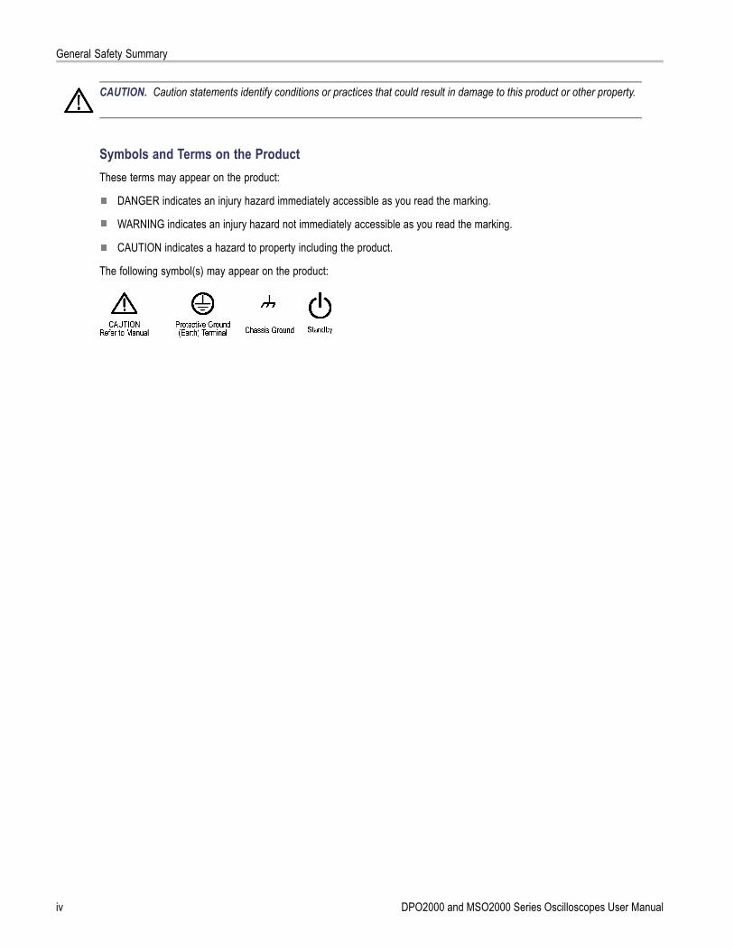
CAUTION. Caution statements identify conditions or practices that could result in damage to this product or other property.
Symbols and Terms on the ProductThese terms may appear on the product:
DANGER indicates an injury hazard immediately accessible as you read the marking.
WARNING indicates an injury hazard not immediately accessible as you read the marking.
CAUTION indicates a hazard to property including the product.
The following symbol(s) may appear on the product:
iv DPO2000 and MSO2000 Series Oscilloscopes User Manual
Compliance Information
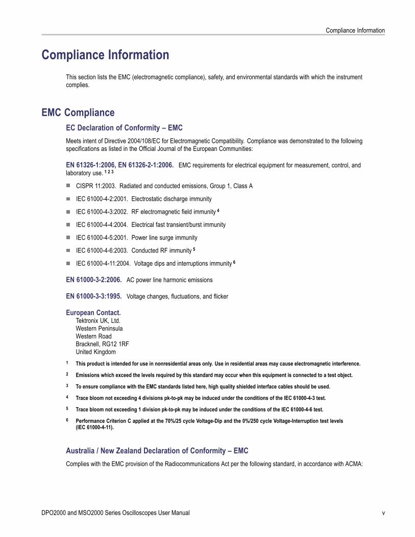
Compliance InformationThis section lists the EMC (electromagnetic compliance), safety, and environmental standards with which the instrumentcomplies.
EMC ComplianceEC Declaration of Conformity – EMCMeets intent of Directive 2004/108/EC for Electromagnetic Compatibility. Compliance was demonstrated to the followingspecifications as listed in the Official Journal of the European Communities:
EN 61326-1:2006, EN 61326-2-1:2006. EMC requirements for electrical equipment for measurement, control, andlaboratory use. 1 2 3
CISPR 11:2003. Radiated and conducted emissions, Group 1, Class A
IEC 61000-4-2:2001. Electrostatic discharge immunity
IEC 61000-4-3:2002. RF electromagnetic field immunity 4
IEC 61000-4-4:2004. Electrical fast transient/burst immunity
IEC 61000-4-5:2001. Power line surge immunity
IEC 61000-4-6:2003. Conducted RF immunity 5
IEC 61000-4-11:2004. Voltage dips and interruptions immunity 6
EN 61000-3-2:2006. AC power line harmonic emissions
EN 61000-3-3:1995. Voltage changes, fluctuations, and flicker
European Contact.Tektronix UK, Ltd.Western PeninsulaWestern RoadBracknell, RG12 1RFUnited Kingdom
1 This product is intended for use in nonresidential areas only. Use in residential areas may cause electromagnetic interference.2 Emissions which exceed the levels required by this standard may occur when this equipment is connected to a test object.3 To ensure compliance with the EMC standards listed here, high quality shielded interface cables should be used.4 Trace bloom not exceeding 4 divisions pk-to-pk may be induced under the conditions of the IEC 61000-4-3 test.5 Trace bloom not exceeding 1 division pk-to-pk may be induced under the conditions of the IEC 61000-4-6 test.6 Performance Criterion C applied at the 70%/25 cycle Voltage-Dip and the 0%/250 cycle Voltage-Interruption test levels
(IEC 61000-4-11).
Australia / New Zealand Declaration of Conformity – EMCComplies with the EMC provision of the Radiocommunications Act per the following standard, in accordance with ACMA:
DPO2000 and MSO2000 Series Oscilloscopes User Manual v

Compliance Information
CISPR 11:2003. Radiated and Conducted Emissions, Group 1, Class A, in accordance with EN 61326-1:2006 andEN 61326-2-1:2006.
vi DPO2000 and MSO2000 Series Oscilloscopes User Manual
Compliance Information
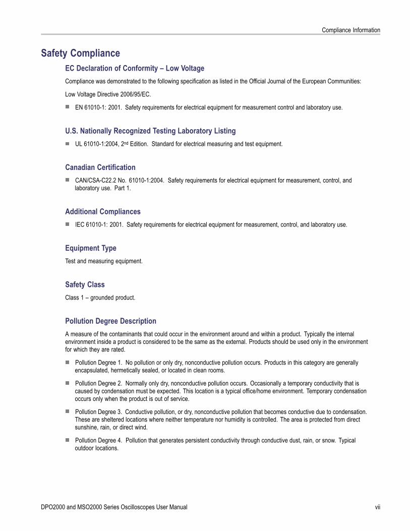
Safety ComplianceEC Declaration of Conformity – Low VoltageCompliance was demonstrated to the following specification as listed in the Official Journal of the European Communities:
Low Voltage Directive 2006/95/EC.
EN 61010-1: 2001. Safety requirements for electrical equipment for measurement control and laboratory use.
U.S. Nationally Recognized Testing Laboratory ListingUL 61010-1:2004, 2nd Edition. Standard for electrical measuring and test equipment.
Canadian CertificationCAN/CSA-C22.2 No. 61010-1:2004. Safety requirements for electrical equipment for measurement, control, andlaboratory use. Part 1.
Additional CompliancesIEC 61010-1: 2001. Safety requirements for electrical equipment for measurement, control, and laboratory use.
Equipment TypeTest and measuring equipment.
Safety ClassClass 1 – grounded product.
Pollution Degree DescriptionA measure of the contaminants that could occur in the environment around and within a product. Typically the internalenvironment inside a product is considered to be the same as the external. Products should be used only in the environmentfor which they are rated.
Pollution Degree 1. No pollution or only dry, nonconductive pollution occurs. Products in this category are generallyencapsulated, hermetically sealed, or located in clean rooms.
Pollution Degree 2. Normally only dry, nonconductive pollution occurs. Occasionally a temporary conductivity that iscaused by condensation must be expected. This location is a typical office/home environment. Temporary condensationoccurs only when the product is out of service.
Pollution Degree 3. Conductive pollution, or dry, nonconductive pollution that becomes conductive due to condensation.These are sheltered locations where neither temperature nor humidity is controlled. The area is protected from directsunshine, rain, or direct wind.
Pollution Degree 4. Pollution that generates persistent conductivity through conductive dust, rain, or snow. Typicaloutdoor locations.
DPO2000 and MSO2000 Series Oscilloscopes User Manual vii

Compliance Information
Pollution DegreePollution Degree 2 (as defined in IEC 61010-1). Note: Rated for indoor use only.
Installation (Overvoltage) Category DescriptionsTerminals on this product may have different installation (overvoltage) category designations. The installation categories are:
Measurement Category IV. For measurements performed at the source of low-voltage installation.
Measurement Category III. For measurements performed in the building installation.
Measurement Category II. For measurements performed on circuits directly connected to the low-voltage installation.
Measurement Category I. For measurements performed on circuits not directly connected to MAINS.
Overvoltage CategoryOvervoltage Category II (as defined in IEC 61010-1).
viii DPO2000 and MSO2000 Series Oscilloscopes User Manual
Compliance Information
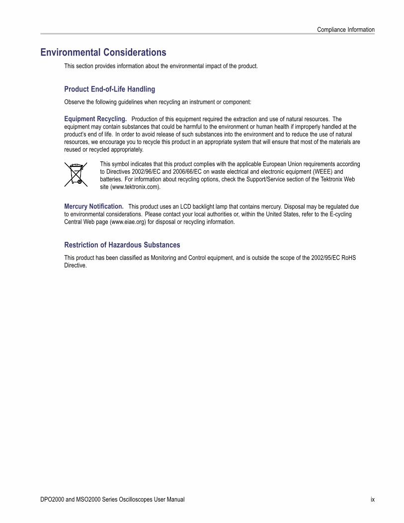
Environmental ConsiderationsThis section provides information about the environmental impact of the product.
Product End-of-Life HandlingObserve the following guidelines when recycling an instrument or component:
Equipment Recycling. Production of this equipment required the extraction and use of natural resources. Theequipment may contain substances that could be harmful to the environment or human health if improperly handled at theproduct’s end of life. In order to avoid release of such substances into the environment and to reduce the use of naturalresources, we encourage you to recycle this product in an appropriate system that will ensure that most of the materials arereused or recycled appropriately.
This symbol indicates that this product complies with the applicable European Union requirements accordingto Directives 2002/96/EC and 2006/66/EC on waste electrical and electronic equipment (WEEE) andbatteries. For information about recycling options, check the Support/Service section of the Tektronix Website (www.tektronix.com).
Mercury Notification. This product uses an LCD backlight lamp that contains mercury. Disposal may be regulated dueto environmental considerations. Please contact your local authorities or, within the United States, refer to the E-cyclingCentral Web page (www.eiae.org) for disposal or recycling information.
Restriction of Hazardous SubstancesThis product has been classified as Monitoring and Control equipment, and is outside the scope of the 2002/95/EC RoHSDirective.
DPO2000 and MSO2000 Series Oscilloscopes User Manual ix
Preface
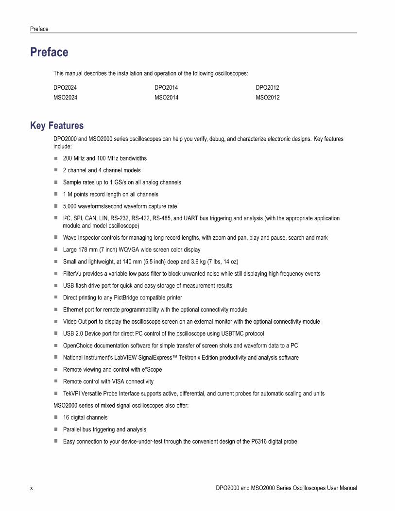
PrefaceThis manual describes the installation and operation of the following oscilloscopes:
DPO2024 DPO2014 DPO2012MSO2024 MSO2014 MSO2012
Key FeaturesDPO2000 and MSO2000 series oscilloscopes can help you verify, debug, and characterize electronic designs. Key featuresinclude:
200 MHz and 100 MHz bandwidths
2 channel and 4 channel models
Sample rates up to 1 GS/s on all analog channels
1 M points record length on all channels
5,000 waveforms/second waveform capture rate
I2C, SPI, CAN, LIN, RS-232, RS-422, RS-485, and UART bus triggering and analysis (with the appropriate applicationmodule and model oscilloscope)
Wave Inspector controls for managing long record lengths, with zoom and pan, play and pause, search and mark
Large 178 mm (7 inch) WQVGA wide screen color display
Small and lightweight, at 140 mm (5.5 inch) deep and 3.6 kg (7 lbs, 14 oz)
FilterVu provides a variable low pass filter to block unwanted noise while still displaying high frequency events
USB flash drive port for quick and easy storage of measurement results
Direct printing to any PictBridge compatible printer
Ethernet port for remote programmability with the optional connectivity module
Video Out port to display the oscilloscope screen on an external monitor with the optional connectivity module
USB 2.0 Device port for direct PC control of the oscilloscope using USBTMC protocol
OpenChoice documentation software for simple transfer of screen shots and waveform data to a PC
National Instrument’s LabVIEW SignalExpress™ Tektronix Edition productivity and analysis software
Remote viewing and control with e*Scope
Remote control with VISA connectivity
TekVPI Versatile Probe Interface supports active, differential, and current probes for automatic scaling and units
MSO2000 series of mixed signal oscilloscopes also offer:
16 digital channels
Parallel bus triggering and analysis
Easy connection to your device-under-test through the convenient design of the P6316 digital probe
x DPO2000 and MSO2000 Series Oscilloscopes User Manual

Preface
Conventions Used in This ManualThe following icons are used throughout this manual.
Sequence Step Front panel power Connect power Network USB
DPO2000 and MSO2000 Series Oscilloscopes User Manual xi

Preface
xii DPO2000 and MSO2000 Series Oscilloscopes User Manual
Installation
Installation
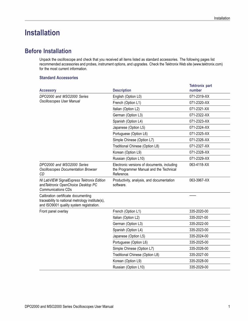
Before InstallationUnpack the oscilloscope and check that you received all items listed as standard accessories. The following pages listrecommended accessories and probes, instrument options, and upgrades. Check the Tektronix Web site (www.tektronix.com)for the most current information.
Standard Accessories
Accessory DescriptionTektronix partnumber
English (Option L0) 071-2319‑XXFrench (Option L1) 071-2320‑XXItalian (Option L2) 071-2321‑XXGerman (Option L3) 071-2322‑XXSpanish (Option L4) 071-2323‑XXJapanese (Option L5) 071-2324‑XXPortuguese (Option L6) 071-2325‑XXSimple Chinese (Option L7) 071-2326‑XXTraditional Chinese (Option L8) 071-2327‑XXKorean (Option L9) 071-2328‑XX
DPO2000 and MSO2000 SeriesOscilloscopes User Manual
Russian (Option L10) 071-2329‑XXDPO2000 and MSO2000 SeriesOscilloscopes Documentation BrowserCD
Electronic versions of documents, includingthe Programmer Manual and the TechnicalReference.
063-4118‑XX
NI LabVIEW SignalExpress Tektronix EditionandTektronix OpenChoice Desktop PCCommunications CDs
Productivity, analysis, and documentationsoftware.
063-3967‑XX
Calibration certificate documentingtraceability to national metrology institute(s),and ISO9001 quality system registration.
——
French (Option L1) 335-2020-00Italian (Option L2) 335-2021-00German (Option L3) 335-2022-00Spanish (Option L4) 335-2023-00Japanese (Option L5) 335-2024-00Portuguese (Option L6) 335-2025-00Simple Chinese (Option L7) 335-2026-00Traditional Chinese (Option L8) 335-2027-00Korean (Option L9) 335-2028-00
Front panel overlay
Russian (Option L10) 335-2029-00
DPO2000 and MSO2000 Series Oscilloscopes User Manual 1

Installation
Standard Accessories (cont.)
Accessory DescriptionTektronix partnumber
For DPO2000 and MSO2000 series: Probes One, 200 MHz, 1X/10X passive probe perchannel
P2221
For MSO2000 series: Digital probe One, 16-channel digital probe P6316For MSO2000 series: Accessories pouch Pouch that attaches to the handle for carrying
probes and other accessories.016-2008-00
Three year warranty For details, refer to the warranty in the front ofthis manual
——
North America (Option A0) 161-0348-00Universal Euro (Option A1) 161-0343-00United Kingdom (Option A2) 161-0344-00Australia (Option A3) 161-0346-00Switzerland (Option A5) 161-0347-00Japan (Option A6) 161-0342-00China (Option A10) 161-0341-00India (Option A11) 161-0349-00
Power cord
No power cord or AC adapter (Option A99) ——
2 DPO2000 and MSO2000 Series Oscilloscopes User Manual
Installation
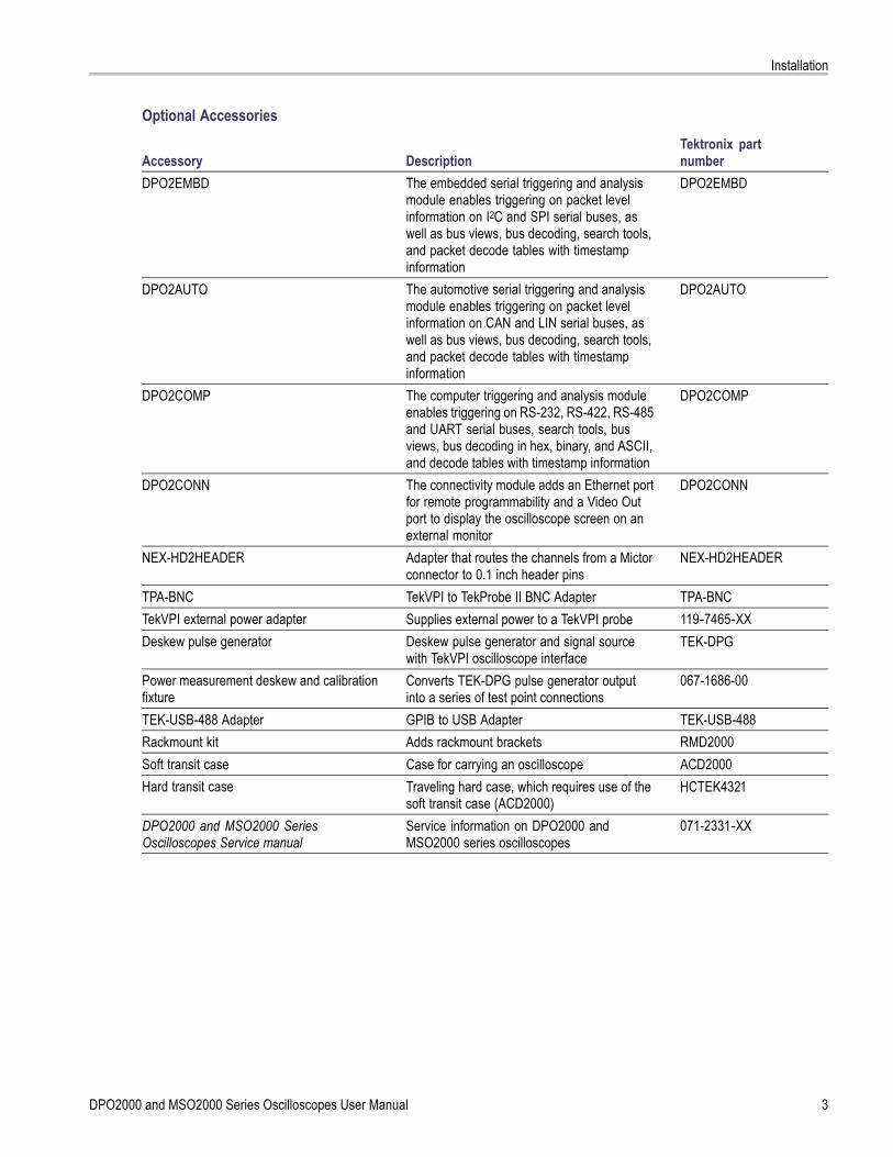
Optional Accessories
Accessory DescriptionTektronix partnumber
DPO2EMBD The embedded serial triggering and analysismodule enables triggering on packet levelinformation on I2C and SPI serial buses, aswell as bus views, bus decoding, search tools,and packet decode tables with timestampinformation
DPO2EMBD
DPO2AUTO The automotive serial triggering and analysismodule enables triggering on packet levelinformation on CAN and LIN serial buses, aswell as bus views, bus decoding, search tools,and packet decode tables with timestampinformation
DPO2AUTO
DPO2COMP The computer triggering and analysis moduleenables triggering on RS-232, RS-422, RS-485and UART serial buses, search tools, busviews, bus decoding in hex, binary, and ASCII,and decode tables with timestamp information
DPO2COMP
DPO2CONN The connectivity module adds an Ethernet portfor remote programmability and a Video Outport to display the oscilloscope screen on anexternal monitor
DPO2CONN
NEX-HD2HEADER Adapter that routes the channels from a Mictorconnector to 0.1 inch header pins
NEX-HD2HEADER
TPA-BNC TekVPI to TekProbe II BNC Adapter TPA-BNCTekVPI external power adapter Supplies external power to a TekVPI probe 119‑7465‑XXDeskew pulse generator Deskew pulse generator and signal source
with TekVPI oscilloscope interfaceTEK-DPG
Power measurement deskew and calibrationfixture
Converts TEK-DPG pulse generator outputinto a series of test point connections
067-1686-00
TEK-USB-488 Adapter GPIB to USB Adapter TEK-USB-488Rackmount kit Adds rackmount brackets RMD2000Soft transit case Case for carrying an oscilloscope ACD2000Hard transit case Traveling hard case, which requires use of the
soft transit case (ACD2000)HCTEK4321
DPO2000 and MSO2000 SeriesOscilloscopes Service manual
Service information on DPO2000 andMSO2000 series oscilloscopes
071-2331‑XX
DPO2000 and MSO2000 Series Oscilloscopes User Manual 3

Installation
Optional Accessories (cont.)
Accessory DescriptionTektronix partnumber
DPO2000 and MSO2000 SeriesOscilloscopes Application Module Installation
Describes how to install application modules inDPO2000 and MSO2000 series oscilloscopes
071-2330‑XX
The DPO2000 and MSO2000 series oscilloscopes work with multiple optional probes. (See page 8, Connecting Probes.)Check the Tektronix Web site (www.tektronix.com) for the most current information.
Related DocumentationAccessory Description Tektronix part numberDPO2000 and MSO2000 SeriesOscilloscopes Programmer Manual
Describes commands for remote controlof the oscilloscope; available electronicallyon the Documentation Browser CD or fordownload from www.tektronix.com/manuals
077-0097‑XX
DPO2000 and MSO2000 SeriesOscilloscopes Technical ReferenceManual
Describes the oscilloscope specificationsand performance verification procedure;available electronically on the DocumentationBrowser CD or for download fromwww.tektronix.com/manuals
077-0096‑XX
4 DPO2000 and MSO2000 Series Oscilloscopes User Manual
Installation
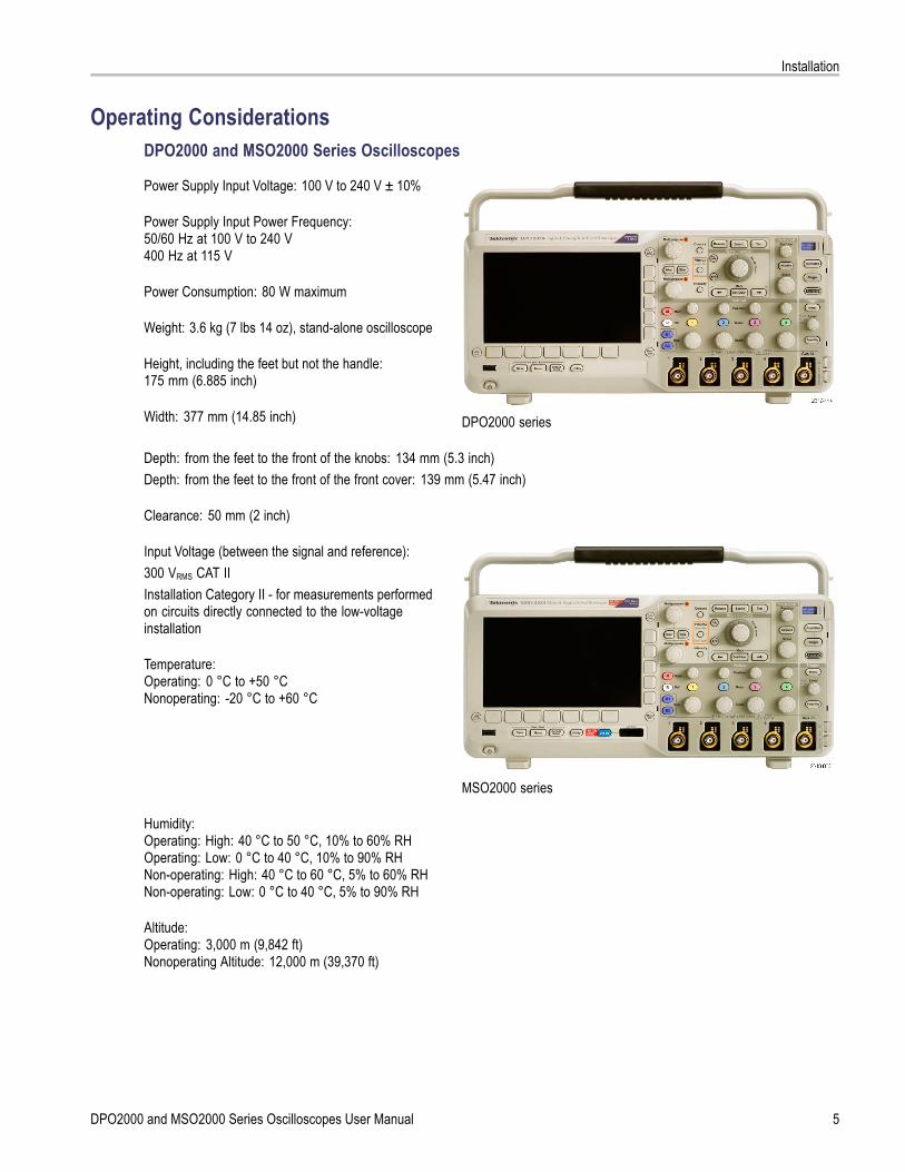
Operating ConsiderationsDPO2000 and MSO2000 Series Oscilloscopes
Power Supply Input Voltage: 100 V to 240 V ± 10%
Power Supply Input Power Frequency:50/60 Hz at 100 V to 240 V400 Hz at 115 V
Power Consumption: 80 W maximum
Weight: 3.6 kg (7 lbs 14 oz), stand-alone oscilloscope
Height, including the feet but not the handle:175 mm (6.885 inch)
Width: 377 mm (14.85 inch) DPO2000 series
Depth: from the feet to the front of the knobs: 134 mm (5.3 inch)Depth: from the feet to the front of the front cover: 139 mm (5.47 inch)
Clearance: 50 mm (2 inch)
Input Voltage (between the signal and reference):300 VRMS CAT IIInstallation Category II - for measurements performedon circuits directly connected to the low-voltageinstallation
Temperature:Operating: 0 °C to +50 °CNonoperating: -20 °C to +60 °C
MSO2000 series
Humidity:Operating: High: 40 °C to 50 °C, 10% to 60% RHOperating: Low: 0 °C to 40 °C, 10% to 90% RHNon-operating: High: 40 °C to 60 °C, 5% to 60% RHNon-operating: Low: 0 °C to 40 °C, 5% to 90% RH
Altitude:Operating: 3,000 m (9,842 ft)Nonoperating Altitude: 12,000 m (39,370 ft)
DPO2000 and MSO2000 Series Oscilloscopes User Manual 5

Installation
Random Vibration:Operating: 0.31 GRMS, 5 - 500 Hz, 10 minutes per axis, 3 axes (30 minutes total)Non-operating: 2.46 GRMS, 5 - 500 Hz, 10 minutes per axis, 3 axes (30 minutes total)
Pollution Degree: 2, Indoor use only
CAUTION. To ensure proper cooling, keep the sides and rear of the oscilloscope clear of obstructions.
P2221 Passive Probe
Input Voltage (between the signal and reference):300 VRMS CAT IIInstallation Category II - for measurements performed on circuits directly connected to the low-voltage installation
Temperature:Operating: 0 °C to +50 °C (+32 °F to +122 °F)Nonoperating: -55 °C to +75 °C ( -67 °F to +167 °F)
Pollution Degree: 2, Indoor use only
Humidity: 10% to 95% RH
MSO2000 Series Oscilloscope with a P6316 Digital Probe
Threshold Accuracy: ±(100 mV + 3% of threshold)
Threshold Range: ±20 V
Maximum nondestructive input signal to probe: ±40 V
Minimum signal swing: 500 mVpeak-to-peak
Input resistance: 101 kΩ
Input capacitance: 8.0 pF
Temperature:Operating: 0 °C to +50 °C (+32 °F to +122 °F)Nonoperating: -40 °C to +71 °C (-40 °F to +160 °F)
Altitude:Operating: 3,000 m (9,843 ft) maximumNonoperating: 12,000 m (39,370 ft) maximum
Pollution Degree: 2, Indoor use only
6 DPO2000 and MSO2000 Series Oscilloscopes User Manual

Installation
Humidity:5% to 95% relative humidity
CleaningInspect the oscilloscope and probes as often as operating conditions require. To clean the exterior surface, perform thefollowing steps:
1. Remove loose dust on the outside of the oscilloscope and probes with a lint-free cloth. Use care to avoid scratching theclear glass display filter.
2. Use a soft cloth dampened with water to clean the oscilloscope. Use an aqueous solution of 75% isopropyl alcoholfor more efficient cleaning.
CAUTION. To avoid damage to the surface of the oscilloscope or probes, do not use any abrasive or chemical cleaningagents.
DPO2000 and MSO2000 Series Oscilloscopes User Manual 7

Installation
Connecting ProbesThe oscilloscope supports probes with the following:
1. Tektronix Versatile Probe Interface(TekVPI)These probes support two-waycommunication with the oscilloscopethrough on-screen menus and remotelythrough programmable support. Theremote control is useful in applicationslike an ATE (automated test environment)where you want the system to presetprobe parameters.
2. TPA-BNC AdapterThe TPA-BNC Adapter allows you touse Tek Probe II probe capabilities,such as providing probe power, andpassing scaling and unit information tothe oscilloscope.
NOTE. To use a TekVPI probe and aTPA-BNC adapter, connect a TekVPIexternal power adapter (Tektronix partnumber 119‑7465‑XX) to the side panelProbe Power connector.
8 DPO2000 and MSO2000 Series Oscilloscopes User Manual
Installation
3. Plain BNC InterfacesSome probes use TekProbe capabilitiesto pass the waveform signal and scalingto the oscilloscope. Other probesonly pass the signal and there is nocommunication.
4. Digital Probe Interface (MSO2000 seriesonly)The P6316 probe provides 16 channelsof digital (on or off state) information.
For more information on the many probes available for use with DPO2000 and MSO2000 series oscilloscopes, refer towww.tektronix.com.
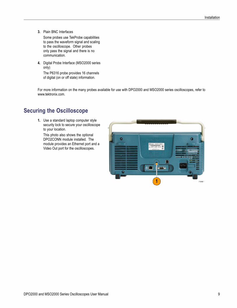
Securing the Oscilloscope1. Use a standard laptop computer style
security lock to secure your oscilloscopeto your location.This photo also shows the optionalDPO2CONN module installed. Themodule provides an Ethernet port and aVideo Out port for the oscilloscopes.
DPO2000 and MSO2000 Series Oscilloscopes User Manual 9
Installation
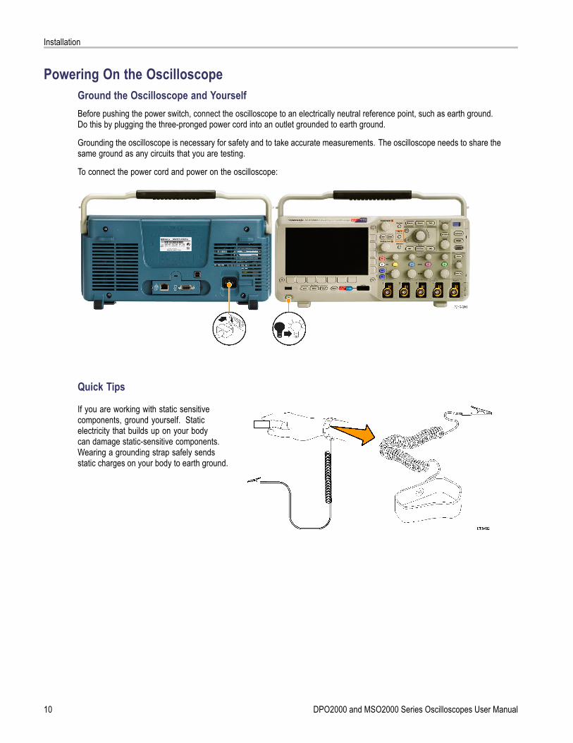
Powering On the OscilloscopeGround the Oscilloscope and YourselfBefore pushing the power switch, connect the oscilloscope to an electrically neutral reference point, such as earth ground.Do this by plugging the three-pronged power cord into an outlet grounded to earth ground.
Grounding the oscilloscope is necessary for safety and to take accurate measurements. The oscilloscope needs to share thesame ground as any circuits that you are testing.
To connect the power cord and power on the oscilloscope:
Quick Tips
If you are working with static sensitivecomponents, ground yourself. Staticelectricity that builds up on your bodycan damage static-sensitive components.Wearing a grounding strap safely sendsstatic charges on your body to earth ground.
10 DPO2000 and MSO2000 Series Oscilloscopes User Manual

Installation
Powering Off the OscilloscopeTo power off the oscilloscope and remove the power cord:
Functional CheckPerform this quick functional check to verify that your oscilloscope is operating correctly.
1. Connect the oscilloscope power cableas described in Powering On theOscilloscope. (See page 10.)
2. Power on the oscilloscope.
DPO2000 and MSO2000 Series Oscilloscopes User Manual 11
Installation
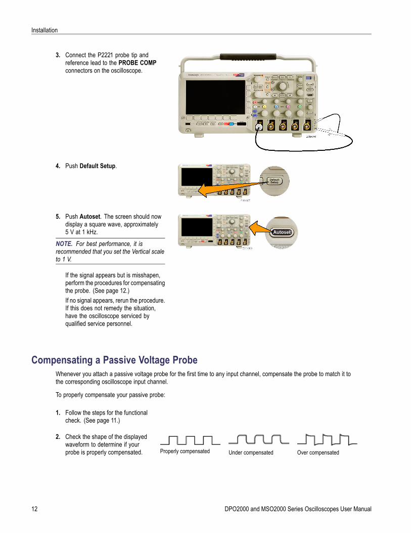
3. Connect the P2221 probe tip andreference lead to the PROBE COMPconnectors on the oscilloscope.
4. Push Default Setup.
5. Push Autoset. The screen should nowdisplay a square wave, approximately5 V at 1 kHz.
NOTE. For best performance, it isrecommended that you set the Vertical scaleto 1 V.
If the signal appears but is misshapen,perform the procedures for compensatingthe probe. (See page 12.)If no signal appears, rerun the procedure.If this does not remedy the situation,have the oscilloscope serviced byqualified service personnel.
Compensating a Passive Voltage ProbeWhenever you attach a passive voltage probe for the first time to any input channel, compensate the probe to match it tothe corresponding oscilloscope input channel.
To properly compensate your passive probe:
1. Follow the steps for the functionalcheck. (See page 11.)
2. Check the shape of the displayedwaveform to determine if yourprobe is properly compensated. Properly compensated Under compensated Over compensated
12 DPO2000 and MSO2000 Series Oscilloscopes User Manual
Installation
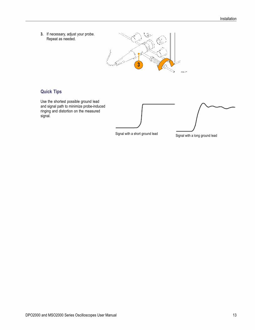
3. If necessary, adjust your probe.Repeat as needed.
Quick Tips
Use the shortest possible ground leadand signal path to minimize probe-inducedringing and distortion on the measuredsignal.
Signal with a short ground lead Signal with a long ground lead
DPO2000 and MSO2000 Series Oscilloscopes User Manual 13
Installation
Application Module Free TrialA 30-day free trial is available for all application modules not installed in your oscilloscope. The trial period begins when youpower on the oscilloscope for the first time.
After 30 days, you must purchase the module if you want to continue using the application. To see the date when your freetrial period expires, push the front panel Utility button, push the lower-bezel Utility Page button, use multipurpose knob a toselect Config, and push the lower-bezel About button.
Installing an Application Module
CAUTION. To avoid damage to the oscilloscope or application module, observe ESD (electrostatic discharge) precautions.(See page 10, Powering On the Oscilloscope.)
Turn off the oscilloscope power while removing or adding an application module.
(See page 11, Powering Off the Oscilloscope.)
Optional application module packages extend the capability of your oscilloscope. You can install one or two applicationmodules at one time. An application module goes into the slot with a window in the upper right corner of the front panel.Another slot is directly behind the one that you can see. To use this slot, install the module with the label facing away from you.
For more information on how to install and test application modules, refer to the DPO2000 and MSO2000 SeriesOscilloscopes Application Module Installation manual.
NOTE. If you remove an application module, the features provided by the application module become unavailable. Torestore the features, turn off the oscilloscope power, reinstall the module and turn on the oscilloscope power.
Changing the User Interface LanguageTo change the language of the oscilloscope user interface, and to change the front-panel button labels through the useof an overlay:
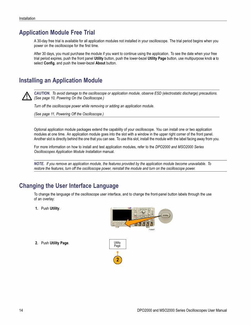
1. Push Utility.
2. Push Utility Page. UtilityPage
14 DPO2000 and MSO2000 Series Oscilloscopes User Manual
Installation
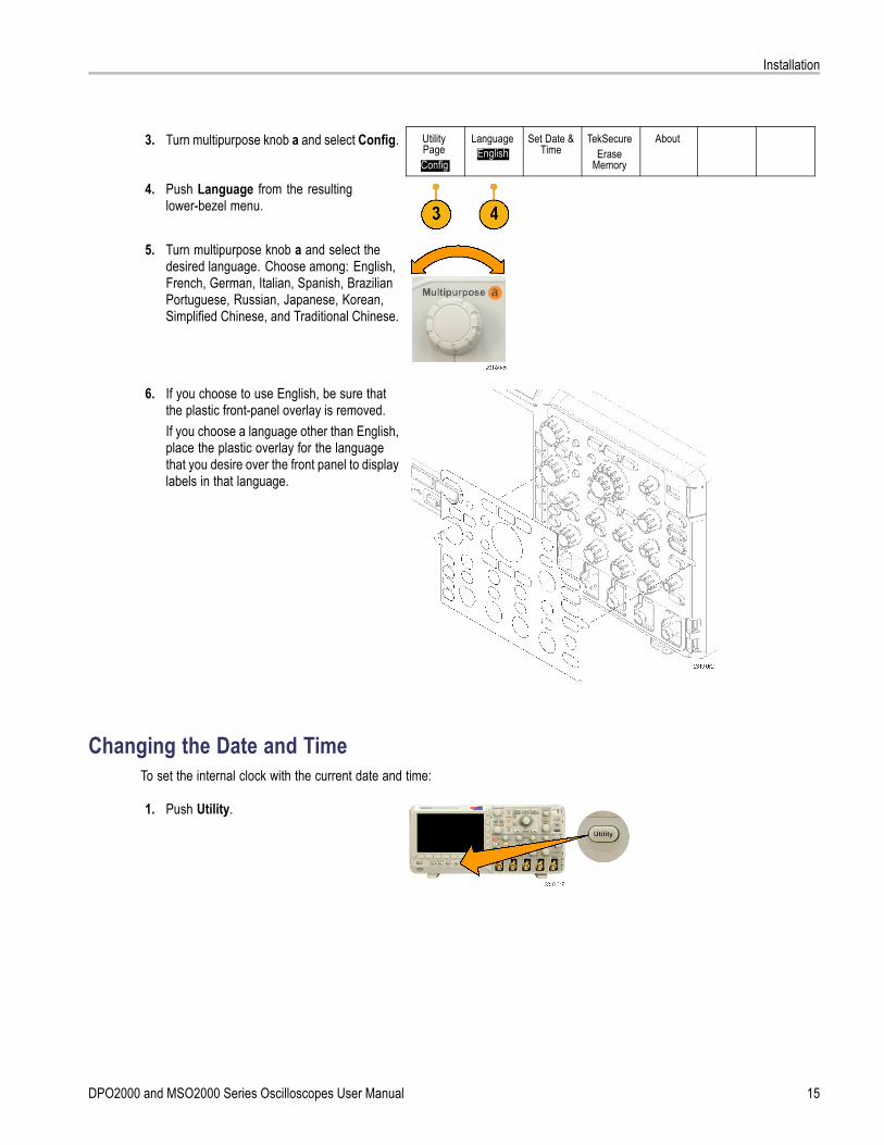
3. Turn multipurpose knob a and select Config. UtilityPageConfig
LanguageEnglish
Set Date &Time
TekSecureErase
Memory
About
4. Push Language from the resultinglower-bezel menu.
5. Turn multipurpose knob a and select thedesired language. Choose among: English,French, German, Italian, Spanish, BrazilianPortuguese, Russian, Japanese, Korean,Simplified Chinese, and Traditional Chinese.
6. If you choose to use English, be sure thatthe plastic front-panel overlay is removed.If you choose a language other than English,place the plastic overlay for the languagethat you desire over the front panel to displaylabels in that language.
Changing the Date and TimeTo set the internal clock with the current date and time:
1. Push Utility.
DPO2000 and MSO2000 Series Oscilloscopes User Manual 15

Installation
2. Push Utility Page. UtilityPage
3. Turn multipurpose knob a and select Config. SystemConfig
LanguageEnglish
Set Date &Time
TekSecureErase
Memory
About
4. Push Set Date & Time.
Set Date &Time
DisplayTime Only
5. Push the side-bezel buttons and usemultipurpose knobs a and b to set the Day,Month, Year, Hour, and Minute values.
SelectDay
6. Push Display and turn multipurpose knob ato choose Date & Time, Date Only, TimeOnly, or None.
Day3
7. Push OK Enter Date & Time. OK EnterDate &Time
16 DPO2000 and MSO2000 Series Oscilloscopes User Manual

Installation
Signal Path CompensationSignal Path Compensation (SPC) corrects for DC inaccuracies caused by temperature variations and/or long-term drift.You should run the SPC whenever the ambient temperature has changed by more than 10 °C or once a week if youuse vertical settings of 5 mV per division or less. Failure to do so may result in the oscilloscope not meeting warrantedperformance levels at those volts per division settings.
To compensate the signal path:
1. Warm up the oscilloscope for at least20 minutes. Remove all input signals(probes and cables) from channel inputs.Input signals with AC components adverselyaffect SPC.
2. Push Utility.
3. Push Utility Page. UtilityPage
4. Turn multipurpose knob a and selectCalibration.
UtilityPage
Calibration
SignalPathPass
FactoryPass
5. Push Signal Path from the lower-bezelmenu.
6. Push OK Compensate Signal Paths fromthe resulting side-bezel menu.
OK Com-pensateSignalPaths
DPO2000 and MSO2000 Series Oscilloscopes User Manual 17
Installation
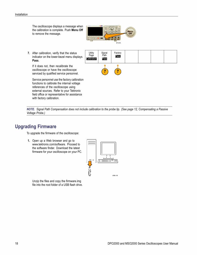
The oscilloscope displays a message whenthe calibration is complete. Push Menu Offto remove the message.
7. After calibration, verify that the statusindicator on the lower-bezel menu displaysPass.
UtilityPage
Calibration
SignalPathPass
FactoryPass
If it does not, then recalibrate theoscilloscope or have the oscilloscopeserviced by qualified service personnel.
Service personnel use the factory calibrationfunctions to calibrate the internal voltagereferences of the oscilloscope usingexternal sources. Refer to your Tektronixfield office or representative for assistancewith factory calibration.
NOTE. Signal Path Compensation does not include calibration to the probe tip. (See page 12, Compensating a PassiveVoltage Probe.)
Upgrading FirmwareTo upgrade the firmware of the oscilloscope:
1. Open up a Web browser and go towww.tektronix.com/software. Proceed tothe software finder. Download the latestfirmware for your oscilloscope on your PC.
Unzip the files and copy the firmware.imgfile into the root folder of a USB flash drive.
18 DPO2000 and MSO2000 Series Oscilloscopes User Manual

Installation
2. Power off your oscilloscope.
3. Insert the USB flash drive into the front-panelUSB port on your oscilloscope.
4. Power on the oscilloscope. The oscilloscopeautomatically recognizes and installs thereplacement firmware.If the oscilloscope does not install thefirmware, rerun the procedure. If theproblem continues, try a different model ofUSB flash drive. Finally, if needed, contactqualified service personnel.
NOTE. Do not power off the oscilloscope orremove the USB flash drive until the oscilloscopefinishes installing the firmware.
DPO2000 and MSO2000 Series Oscilloscopes User Manual 19
Installation
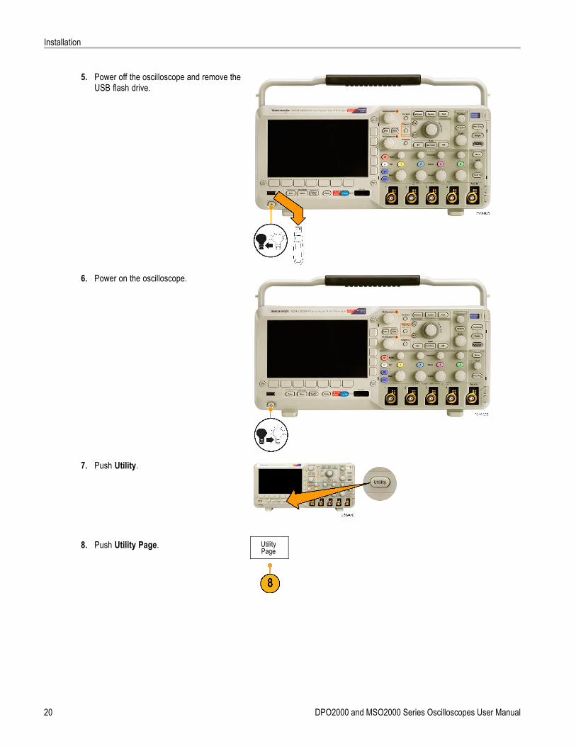
5. Power off the oscilloscope and remove theUSB flash drive.
6. Power on the oscilloscope.
7. Push Utility.
8. Push Utility Page. UtilityPage
20 DPO2000 and MSO2000 Series Oscilloscopes User Manual

Installation
9. Turn multipurpose knob a and select Config. UtilityPageConfig
LanguageEnglish
Set Date &Time
TekSecureErase
Memory
About
10. Push About. The oscilloscope displays thefirmware version number.
11. Confirm that the version number matchesthat of the new firmware.
Connecting Your Oscilloscope to a ComputerYou may want to document your work for future reference. Instead of saving screen images and waveform data to a USBflash drive and generating a report later, you may want to get a copy of the image or waveform data directly from a remotePC for analysis. You may also want to control an oscilloscope at a remote location from your computer. (See page 111,Saving a Screen Image.) (See page 112, Saving and Recalling Waveform Data.)
Two ways to connect your oscilloscope to a computer are through the VISA (Virtual Instrument Software Architecture) driversand the e*Scope Web-enabled tools. Use VISA to communicate with your oscilloscope from your computer through asoftware application. Use e*Scope to communicate with your oscilloscope through a Web browser.
Using VISAVISA lets you use your MS-Windows computer to acquire data from your oscilloscope for use in an analysis package thatruns on your PC, such as Microsoft Excel, National Instruments LabVIEW, or a program of your own creation. You can use acommon communications connection, such as USB or Ethernet, to connect the computer to the oscilloscope.
To set up VISA communications between your oscilloscope and a computer:
1. Load the VISA drivers on your computer.You will find the drivers on the appropriateCD that comes with your oscilloscope orat the Tektronix software finder Web page(www.tektronix.com).
DPO2000 and MSO2000 Series Oscilloscopes User Manual 21
Installation
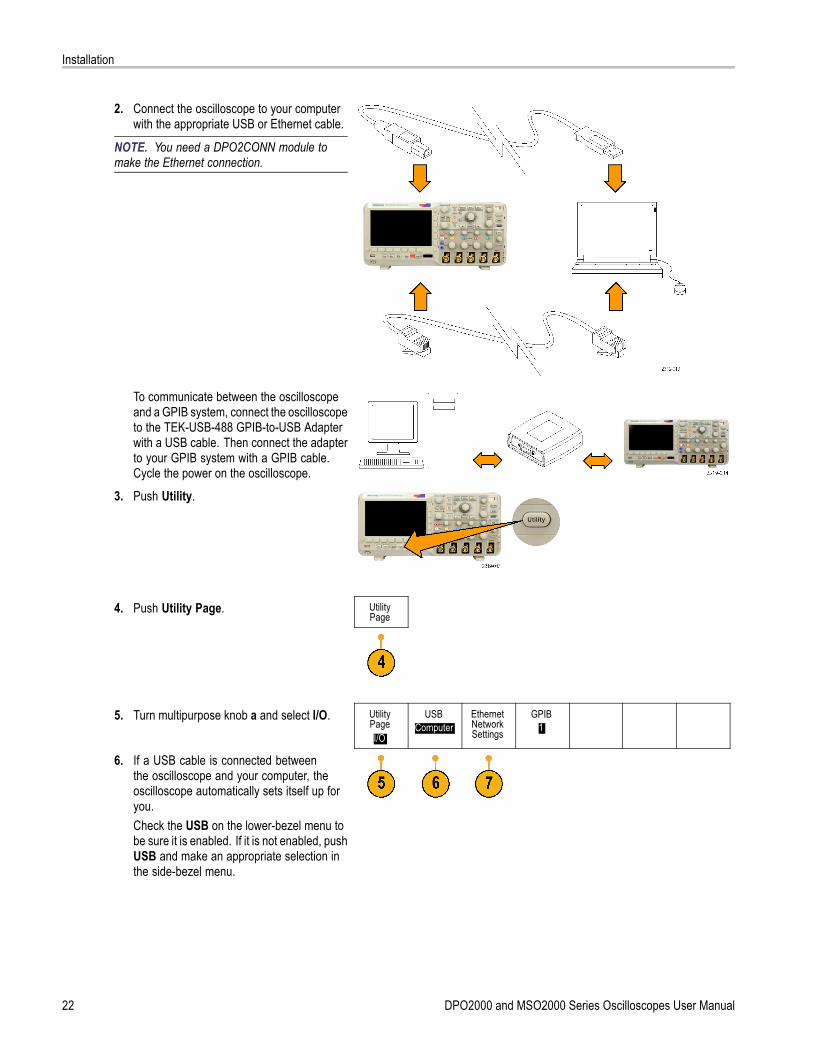
2. Connect the oscilloscope to your computerwith the appropriate USB or Ethernet cable.
NOTE. You need a DPO2CONN module tomake the Ethernet connection.
To communicate between the oscilloscopeand a GPIB system, connect the oscilloscopeto the TEK-USB-488 GPIB-to-USB Adapterwith a USB cable. Then connect the adapterto your GPIB system with a GPIB cable.Cycle the power on the oscilloscope.
3. Push Utility.
4. Push Utility Page. UtilityPage
5. Turn multipurpose knob a and select I/O. UtilityPageI/O
USBComputer
EthernetNetworkSettings
GPIB1
6. If a USB cable is connected betweenthe oscilloscope and your computer, theoscilloscope automatically sets itself up foryou.Check the USB on the lower-bezel menu tobe sure it is enabled. If it is not enabled, pushUSB and make an appropriate selection inthe side-bezel menu.
22 DPO2000 and MSO2000 Series Oscilloscopes User Manual
Installation
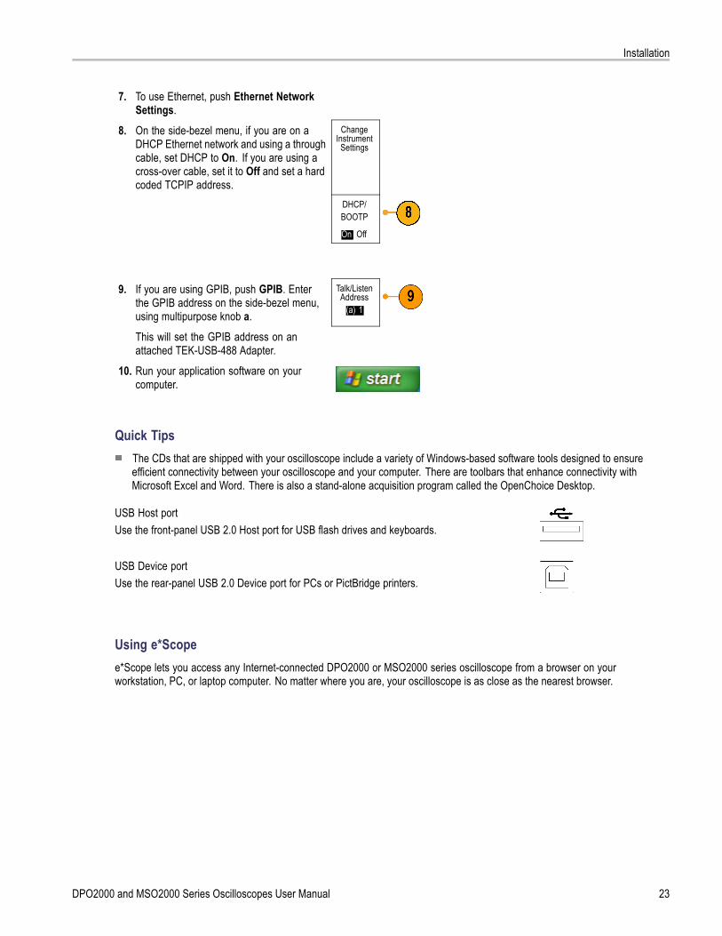
7. To use Ethernet, push Ethernet NetworkSettings.
8. On the side-bezel menu, if you are on aDHCP Ethernet network and using a throughcable, set DHCP to On. If you are using across-over cable, set it to Off and set a hardcoded TCPIP address.
ChangeInstrument
Settings
DHCP/BOOTP
On| Off
9. If you are using GPIB, push GPIB. Enterthe GPIB address on the side-bezel menu,using multipurpose knob a.
Talk/ListenAddress
(a) 1
This will set the GPIB address on anattached TEK-USB-488 Adapter.
10. Run your application software on yourcomputer.
Quick TipsThe CDs that are shipped with your oscilloscope include a variety of Windows-based software tools designed to ensureefficient connectivity between your oscilloscope and your computer. There are toolbars that enhance connectivity withMicrosoft Excel and Word. There is also a stand-alone acquisition program called the OpenChoice Desktop.
USB Host portUse the front-panel USB 2.0 Host port for USB flash drives and keyboards.
USB Device portUse the rear-panel USB 2.0 Device port for PCs or PictBridge printers.
Using e*Scopee*Scope lets you access any Internet-connected DPO2000 or MSO2000 series oscilloscope from a browser on yourworkstation, PC, or laptop computer. No matter where you are, your oscilloscope is as close as the nearest browser.
DPO2000 and MSO2000 Series Oscilloscopes User Manual 23
Installation
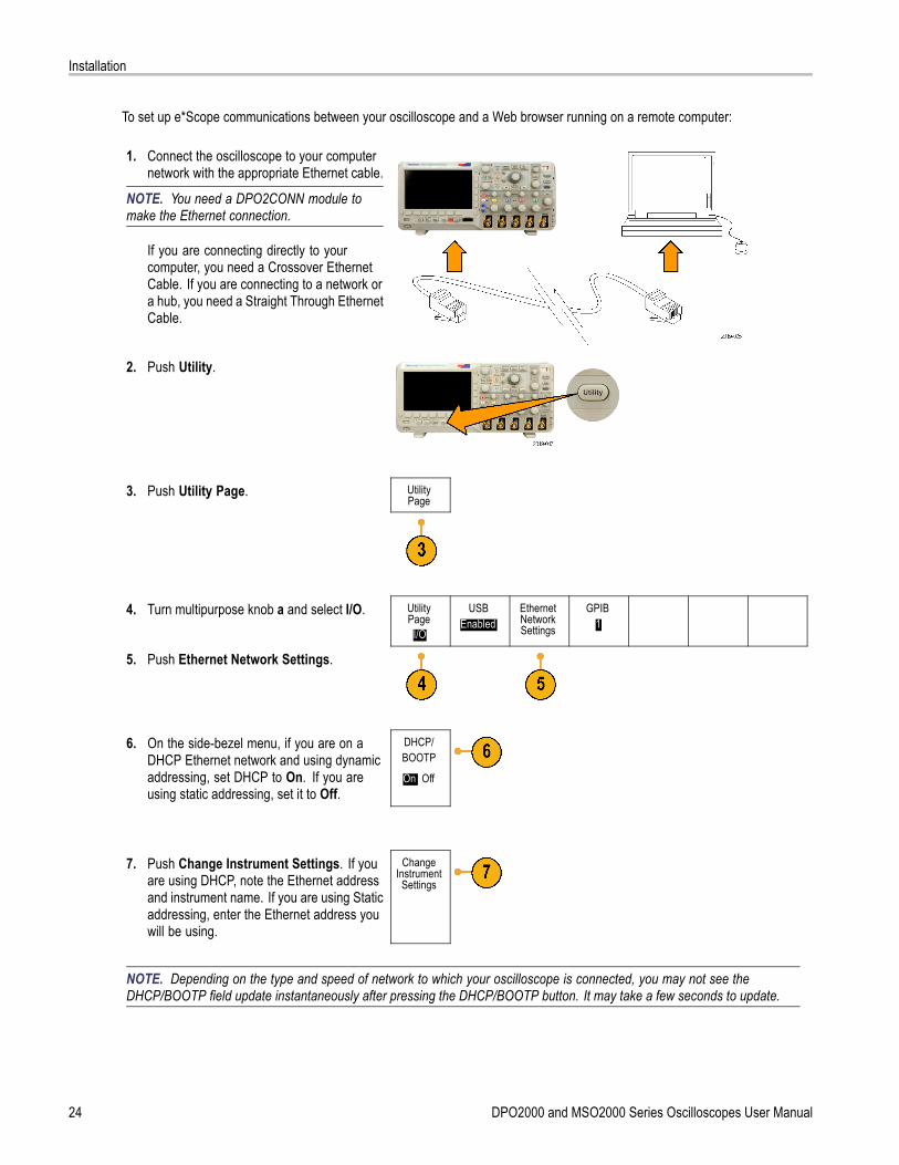
To set up e*Scope communications between your oscilloscope and a Web browser running on a remote computer:
1. Connect the oscilloscope to your computernetwork with the appropriate Ethernet cable.
NOTE. You need a DPO2CONN module tomake the Ethernet connection.
If you are connecting directly to yourcomputer, you need a Crossover EthernetCable. If you are connecting to a network ora hub, you need a Straight Through EthernetCable.
2. Push Utility.
3. Push Utility Page. UtilityPage
4. Turn multipurpose knob a and select I/O. UtilityPage
I/O
USBEnabled
EthernetNetworkSettings
GPIB1
5. Push Ethernet Network Settings.
6. On the side-bezel menu, if you are on aDHCP Ethernet network and using dynamicaddressing, set DHCP to On. If you areusing static addressing, set it to Off.
DHCP/BOOTP
On| Off
7. Push Change Instrument Settings. If youare using DHCP, note the Ethernet addressand instrument name. If you are using Staticaddressing, enter the Ethernet address youwill be using.
ChangeInstrument
Settings
NOTE. Depending on the type and speed of network to which your oscilloscope is connected, you may not see theDHCP/BOOTP field update instantaneously after pressing the DHCP/BOOTP button. It may take a few seconds to update.
24 DPO2000 and MSO2000 Series Oscilloscopes User Manual
Installation
8. Start your browser on your remote computer. In the browser address line, enter the IP address or, if DHCP is set to Onin the oscilloscope, simply enter the instrument name.You should now see the e*Scope screen showing the oscilloscope display on your Web browser. If e*Scope does notwork, rerun the procedure. If it still does not work, contact qualified service personnel.
Connecting a USB Keyboard to Your OscilloscopeYou can connect a USB keyboard to the USB Host port on the front panel of the oscilloscope. The oscilloscope will detect thekeyboard, even if it is plugged in while the oscilloscope is powered on. (See page 42, Labeling Channels and Buses.)
DPO2000 and MSO2000 Series Oscilloscopes User Manual 25

Installation
26 DPO2000 and MSO2000 Series Oscilloscopes User Manual
Getting Acquainted with the Oscilloscope
Getting Acquainted with the Oscilloscope
Front-Panel Menus and ControlsThe front panel has buttons and controls for the functions that you use most often. Use the menu buttons to accessmore specialized functions.
Using the Menu System
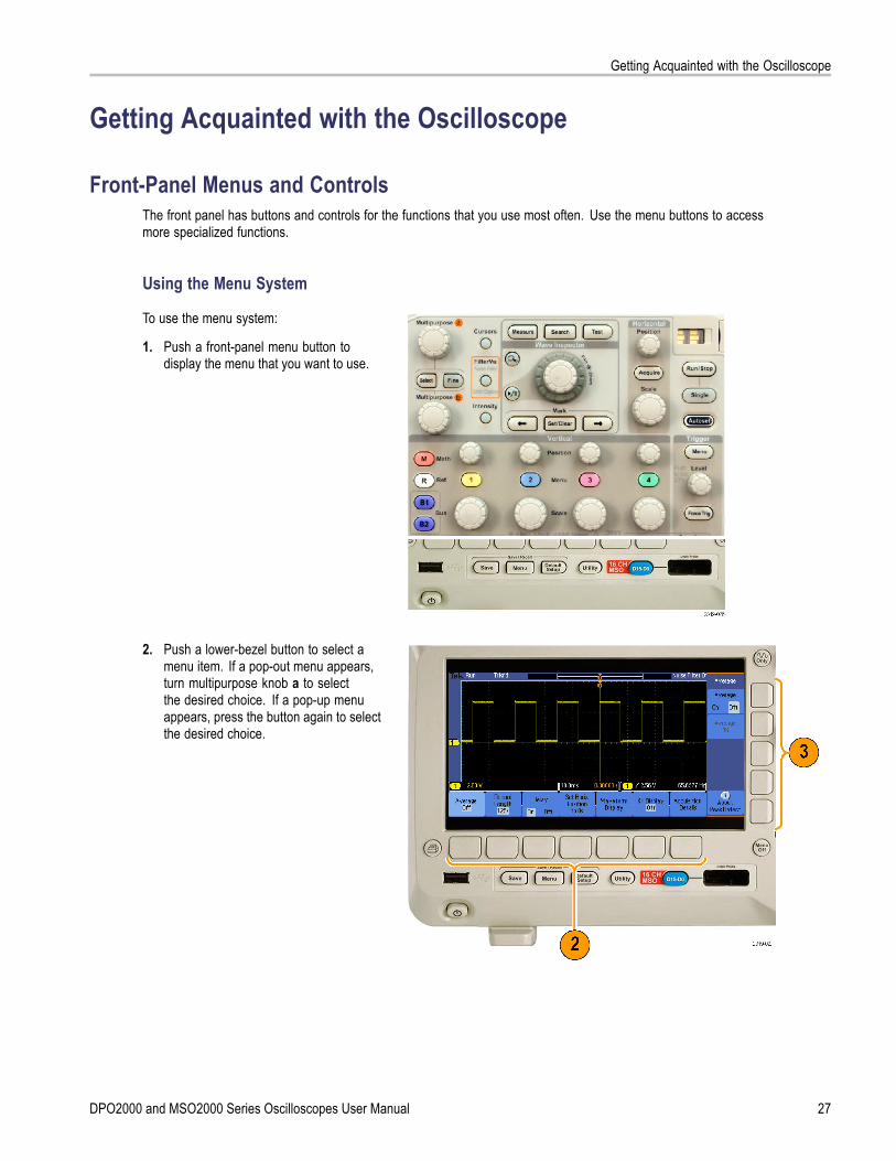
To use the menu system:
1. Push a front-panel menu button todisplay the menu that you want to use.
2. Push a lower-bezel button to select amenu item. If a pop-out menu appears,turn multipurpose knob a to selectthe desired choice. If a pop-up menuappears, press the button again to selectthe desired choice.
DPO2000 and MSO2000 Series Oscilloscopes User Manual 27

Getting Acquainted with the Oscilloscope
3. Push a side-bezel button to choose aside-bezel menu item.If the menu item contains more thanone choice, push the side-bezel buttonrepeatedly to cycle through the choices.If a pop-out menu appears, turnmultipurpose knob a to select the desiredchoice.
4. To remove a side-bezel menu, push thelower-bezel button again or push MenuOff.
28 DPO2000 and MSO2000 Series Oscilloscopes User Manual
Getting Acquainted with the Oscilloscope
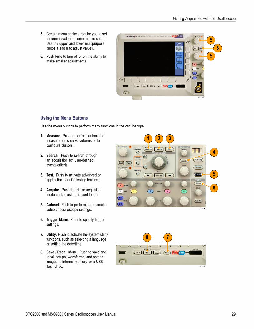
5. Certain menu choices require you to seta numeric value to complete the setup.Use the upper and lower multipurposeknobs a and b to adjust values.
6. Push Fine to turn off or on the ability tomake smaller adjustments.
Using the Menu ButtonsUse the menu buttons to perform many functions in the oscilloscope.
1. Measure. Push to perform automatedmeasurements on waveforms or toconfigure cursors.
2. Search. Push to search throughan acquisition for user-definedevents/criteria.
3. Test. Push to activate advanced orapplication-specific testing features.
4. Acquire. Push to set the acquisitionmode and adjust the record length.
5. Autoset. Push to perform an automaticsetup of oscilloscope settings.
6. Trigger Menu. Push to specify triggersettings.
7. Utility. Push to activate the system utilityfunctions, such as selecting a languageor setting the date/time.
8. Save / Recall Menu. Push to save andrecall setups, waveforms, and screenimages to internal memory, or a USBflash drive.
DPO2000 and MSO2000 Series Oscilloscopes User Manual 29
Getting Acquainted with the Oscilloscope
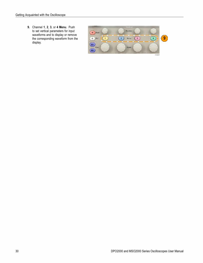
9. Channel 1, 2, 3, or 4 Menu. Pushto set vertical parameters for inputwaveforms and to display or removethe corresponding waveform from thedisplay.
30 DPO2000 and MSO2000 Series Oscilloscopes User Manual
Getting Acquainted with the Oscilloscope
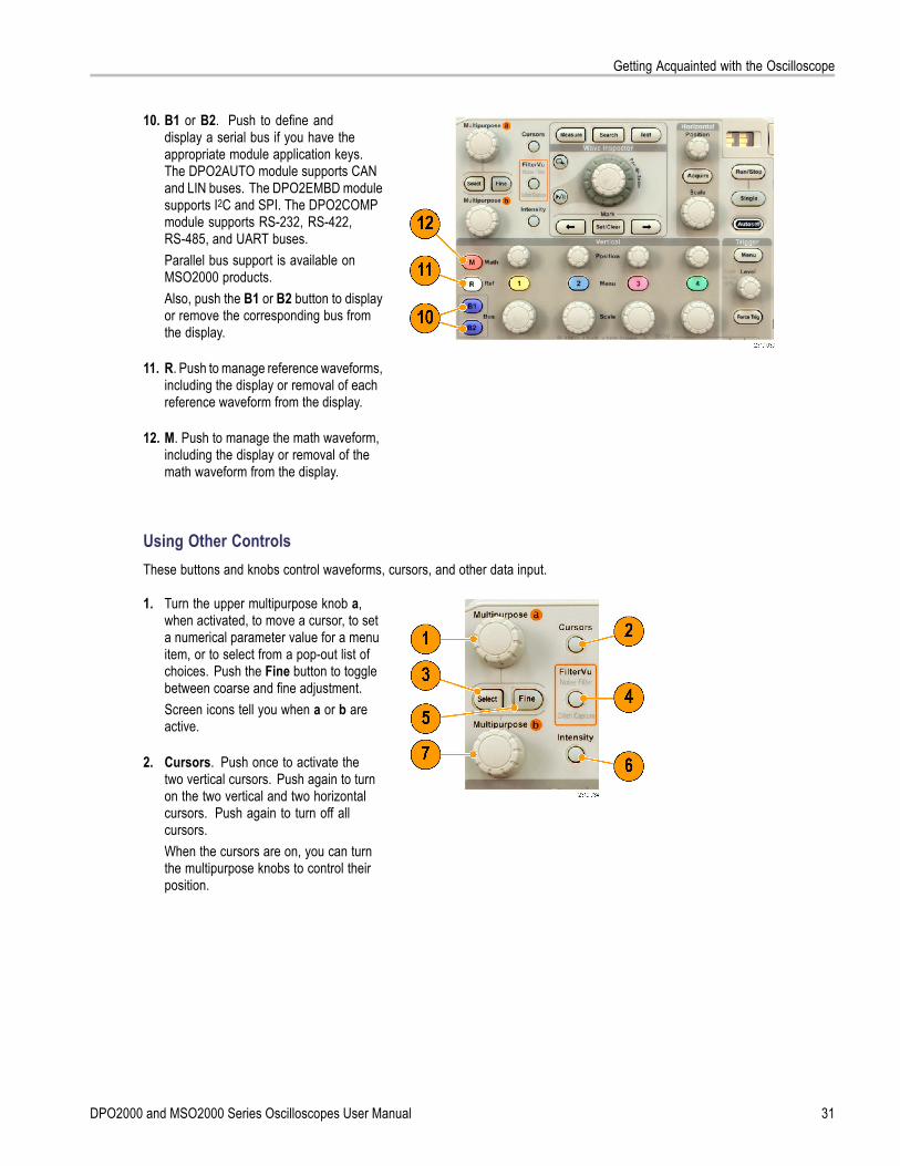
10. B1 or B2. Push to define anddisplay a serial bus if you have theappropriate module application keys.The DPO2AUTO module supports CANand LIN buses. The DPO2EMBD modulesupports I2C and SPI. The DPO2COMPmodule supports RS-232, RS-422,RS-485, and UART buses.Parallel bus support is available onMSO2000 products.Also, push the B1 or B2 button to displayor remove the corresponding bus fromthe display.
11. R. Push to manage reference waveforms,including the display or removal of eachreference waveform from the display.
12. M. Push to manage the math waveform,including the display or removal of themath waveform from the display.
Using Other ControlsThese buttons and knobs control waveforms, cursors, and other data input.
1. Turn the upper multipurpose knob a,when activated, to move a cursor, to seta numerical parameter value for a menuitem, or to select from a pop-out list ofchoices. Push the Fine button to togglebetween coarse and fine adjustment.Screen icons tell you when a or b areactive.
2. Cursors. Push once to activate thetwo vertical cursors. Push again to turnon the two vertical and two horizontalcursors. Push again to turn off allcursors.When the cursors are on, you can turnthe multipurpose knobs to control theirposition.
DPO2000 and MSO2000 Series Oscilloscopes User Manual 31
Getting Acquainted with the Oscilloscope
3. Select. Push to activate specialfunctions.For example, when using the two verticalcursors (and no horizontal ones arevisible), you can push this button to linkor unlink the cursors. When the twovertical and two horizontal cursors areboth visible, you can push this button tomake either the vertical cursors or thehorizontal cursors active.
4. FilterVu. Push to filter unwanted noisefrom your signal and still capture glitches.
5. Fine. Push to toggle between makingcoarse and fine adjustments with thevertical and horizontal position knobs, thetrigger level knob, and many operationsof multipurpose knobs a and b.
6. Intensity. Push to enable multipurposeknob a to control waveform displayintensity and knob b to control graticuleintensity.
7. Turn the lower multipurpose knob b,when activated, to move a cursor or seta numerical parameter value for a menuitem. Push Fine to make adjustmentsmore slowly.
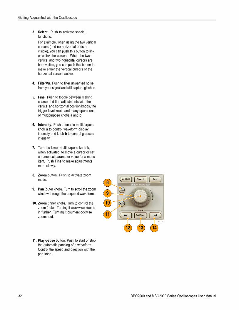
8. Zoom button. Push to activate zoommode.
9. Pan (outer knob). Turn to scroll the zoomwindow through the acquired waveform.
10. Zoom (inner knob). Turn to control thezoom factor. Turning it clockwise zoomsin further. Turning it counterclockwisezooms out.
11. Play-pause button. Push to start or stopthe automatic panning of a waveform.Control the speed and direction with thepan knob.
32 DPO2000 and MSO2000 Series Oscilloscopes User Manual

Getting Acquainted with the Oscilloscope
12. ← Prev. Push to jump to the previouswaveform mark.
13. Set/Clear Mark. Push to establish ordelete a waveform mark.
14. → Next. Push to jump to the nextwaveform mark.
15. Horizontal Position. Turn to adjustthe trigger point location relative to theacquired waveforms. Push Fine to makesmaller adjustments.
16. Horizontal Scale. Turn to adjust thehorizontal scale (time/division).
17. Run/Stop. Push to start or stopacquisitions.
18. Single. Push to make a singleacquisition.
19. Autoset. Push to automatically set thevertical, horizontal, and trigger controlsfor a usable, stable display.
20. Trigger Level. Turn to adjust the triggerlevel.Push Level to Set 50%. Push theTrigger level knob to set the trigger levelto the midpoint of the waveform.
21. Force Trig. Push to force an immediatetrigger event.
22. Vertical Position. Turn to adjust thevertical position of the correspondingwaveform. Push Fine to make smalleradjustments.
23. 1, 2, 3, 4 Menu. Push to display orremove the corresponding waveformfrom the display and access the verticalmenu.
DPO2000 and MSO2000 Series Oscilloscopes User Manual 33
Getting Acquainted with the Oscilloscope
24. Vertical Scale. Turn to adjust thevertical scale factor of the correspondingwaveform (volts/division).
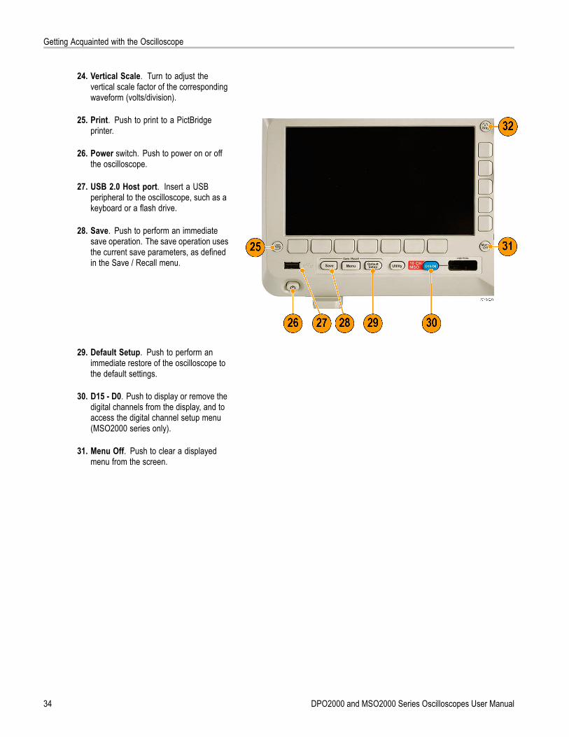
25. Print. Push to print to a PictBridgeprinter.
26. Power switch. Push to power on or offthe oscilloscope.
27. USB 2.0 Host port. Insert a USBperipheral to the oscilloscope, such as akeyboard or a flash drive.
28. Save. Push to perform an immediatesave operation. The save operation usesthe current save parameters, as definedin the Save / Recall menu.
29. Default Setup. Push to perform animmediate restore of the oscilloscope tothe default settings.
30. D15 - D0. Push to display or remove thedigital channels from the display, and toaccess the digital channel setup menu(MSO2000 series only).
31. Menu Off. Push to clear a displayedmenu from the screen.
34 DPO2000 and MSO2000 Series Oscilloscopes User Manual
Getting Acquainted with the Oscilloscope
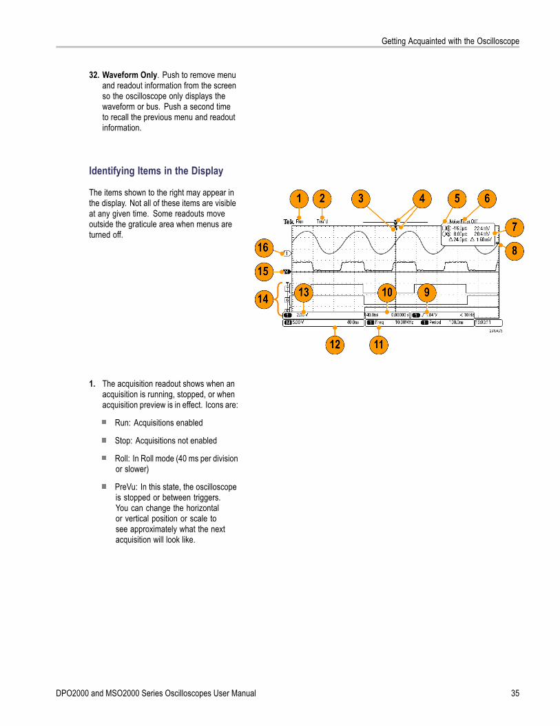
32. Waveform Only. Push to remove menuand readout information from the screenso the oscilloscope only displays thewaveform or bus. Push a second timeto recall the previous menu and readoutinformation.
Identifying Items in the Display
The items shown to the right may appear inthe display. Not all of these items are visibleat any given time. Some readouts moveoutside the graticule area when menus areturned off.
1. The acquisition readout shows when anacquisition is running, stopped, or whenacquisition preview is in effect. Icons are:
Run: Acquisitions enabled
Stop: Acquisitions not enabled
Roll: In Roll mode (40 ms per divisionor slower)
PreVu: In this state, the oscilloscopeis stopped or between triggers.You can change the horizontalor vertical position or scale tosee approximately what the nextacquisition will look like.
DPO2000 and MSO2000 Series Oscilloscopes User Manual 35
Getting Acquainted with the Oscilloscope
2. The trigger status readout shows triggerstatus. Status conditions are:
Trig’d: Triggered
Auto: Acquiring untriggered data
PrTrig: Acquiring pretrigger data
Trig?: Waiting for trigger
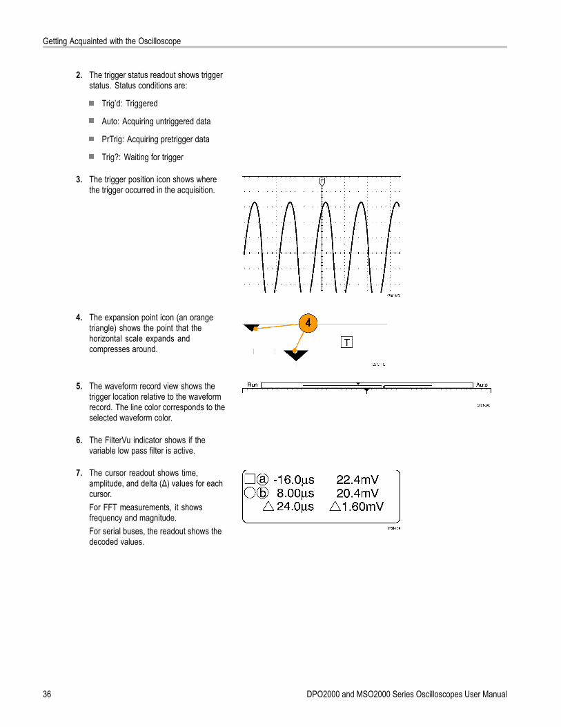
3. The trigger position icon shows wherethe trigger occurred in the acquisition.
4. The expansion point icon (an orangetriangle) shows the point that thehorizontal scale expands andcompresses around.
5. The waveform record view shows thetrigger location relative to the waveformrecord. The line color corresponds to theselected waveform color.
6. The FilterVu indicator shows if thevariable low pass filter is active.
7. The cursor readout shows time,amplitude, and delta (Δ) values for eachcursor.For FFT measurements, it showsfrequency and magnitude.For serial buses, the readout shows thedecoded values.
36 DPO2000 and MSO2000 Series Oscilloscopes User Manual
Getting Acquainted with the Oscilloscope
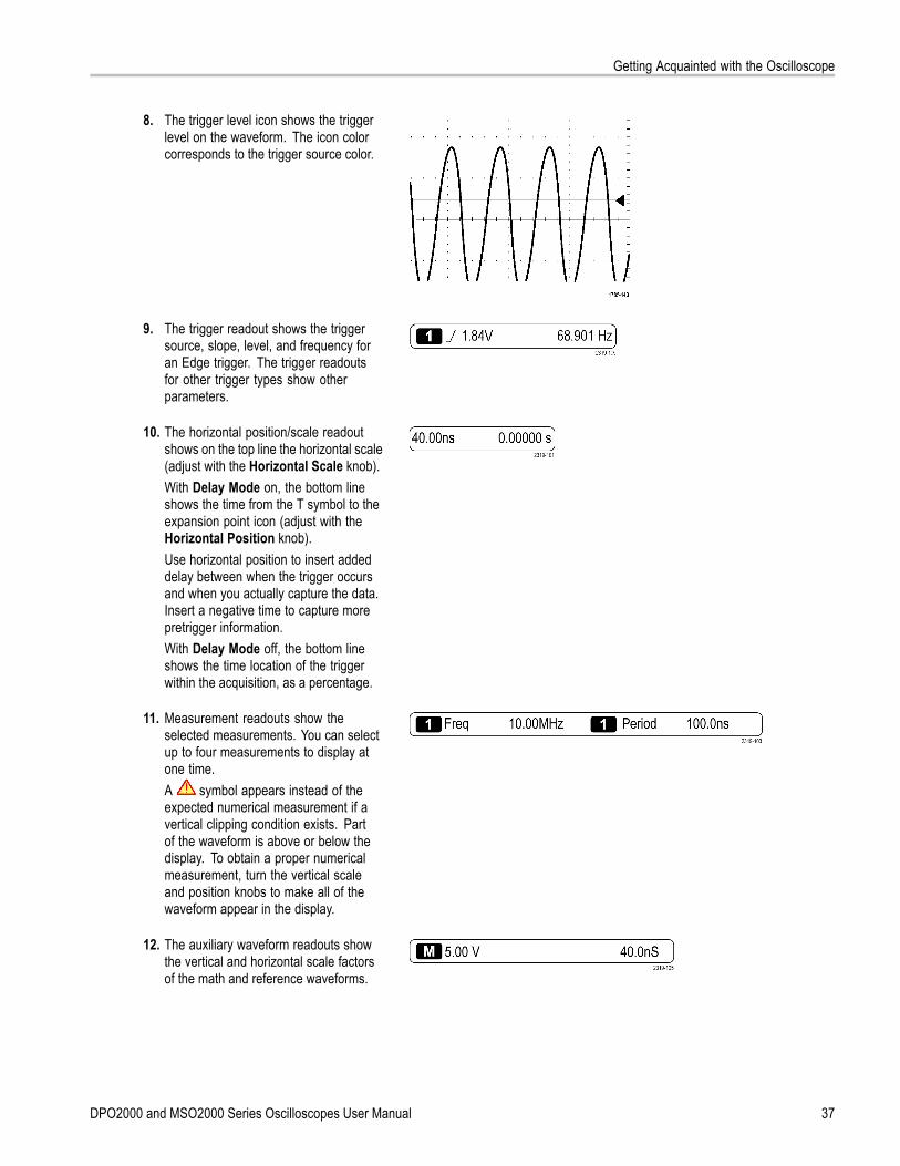
8. The trigger level icon shows the triggerlevel on the waveform. The icon colorcorresponds to the trigger source color.
9. The trigger readout shows the triggersource, slope, level, and frequency foran Edge trigger. The trigger readoutsfor other trigger types show otherparameters.
10. The horizontal position/scale readoutshows on the top line the horizontal scale(adjust with the Horizontal Scale knob).With Delay Mode on, the bottom lineshows the time from the T symbol to theexpansion point icon (adjust with theHorizontal Position knob).Use horizontal position to insert addeddelay between when the trigger occursand when you actually capture the data.Insert a negative time to capture morepretrigger information.With Delay Mode off, the bottom lineshows the time location of the triggerwithin the acquisition, as a percentage.
11. Measurement readouts show theselected measurements. You can selectup to four measurements to display atone time.A symbol appears instead of theexpected numerical measurement if avertical clipping condition exists. Partof the waveform is above or below thedisplay. To obtain a proper numericalmeasurement, turn the vertical scaleand position knobs to make all of thewaveform appear in the display.
12. The auxiliary waveform readouts showthe vertical and horizontal scale factorsof the math and reference waveforms.
DPO2000 and MSO2000 Series Oscilloscopes User Manual 37
Getting Acquainted with the Oscilloscope
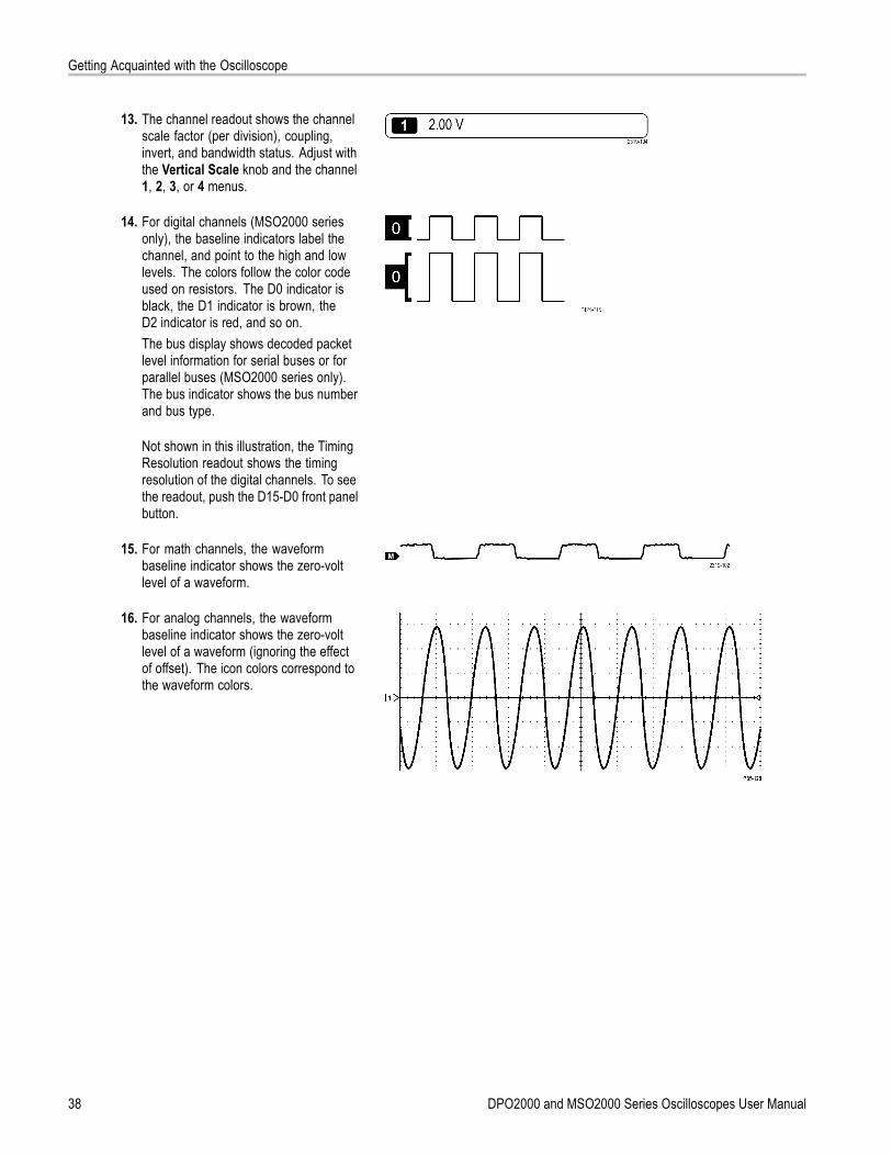
13. The channel readout shows the channelscale factor (per division), coupling,invert, and bandwidth status. Adjust withthe Vertical Scale knob and the channel1, 2, 3, or 4 menus.
14. For digital channels (MSO2000 seriesonly), the baseline indicators label thechannel, and point to the high and lowlevels. The colors follow the color codeused on resistors. The D0 indicator isblack, the D1 indicator is brown, theD2 indicator is red, and so on.The bus display shows decoded packetlevel information for serial buses or forparallel buses (MSO2000 series only).The bus indicator shows the bus numberand bus type.
Not shown in this illustration, the TimingResolution readout shows the timingresolution of the digital channels. To seethe readout, push the D15-D0 front panelbutton.
15. For math channels, the waveformbaseline indicator shows the zero-voltlevel of a waveform.
16. For analog channels, the waveformbaseline indicator shows the zero-voltlevel of a waveform (ignoring the effectof offset). The icon colors correspond tothe waveform colors.
38 DPO2000 and MSO2000 Series Oscilloscopes User Manual

Getting Acquainted with the Oscilloscope
Front-Panel Connectors1. Digital Probe Connector
(MSO2000 series only).
2. Channel 1, 2, (3, 4). Channel inputs withTekVPI Versatile Probe Interface.
3. Aux In. Trigger level range is adjustablefrom +12.5 V to –12.5 V.
4. PROBE COMP. Square wave signalsource to compensate probes.Output voltage: 0 V to 5 VFrequency: 1 kHz
5. Ground.
6. Application Module Slots.
Side-Panel Connector1. TekVPI external power supply connector.
Use the connector for the TekVPIexternal power supply (Tektronix partnumber 119‑7465‑XX) when additionalpower is needed for TekVPI probes.
DPO2000 and MSO2000 Series Oscilloscopes User Manual 39
Getting Acquainted with the Oscilloscope
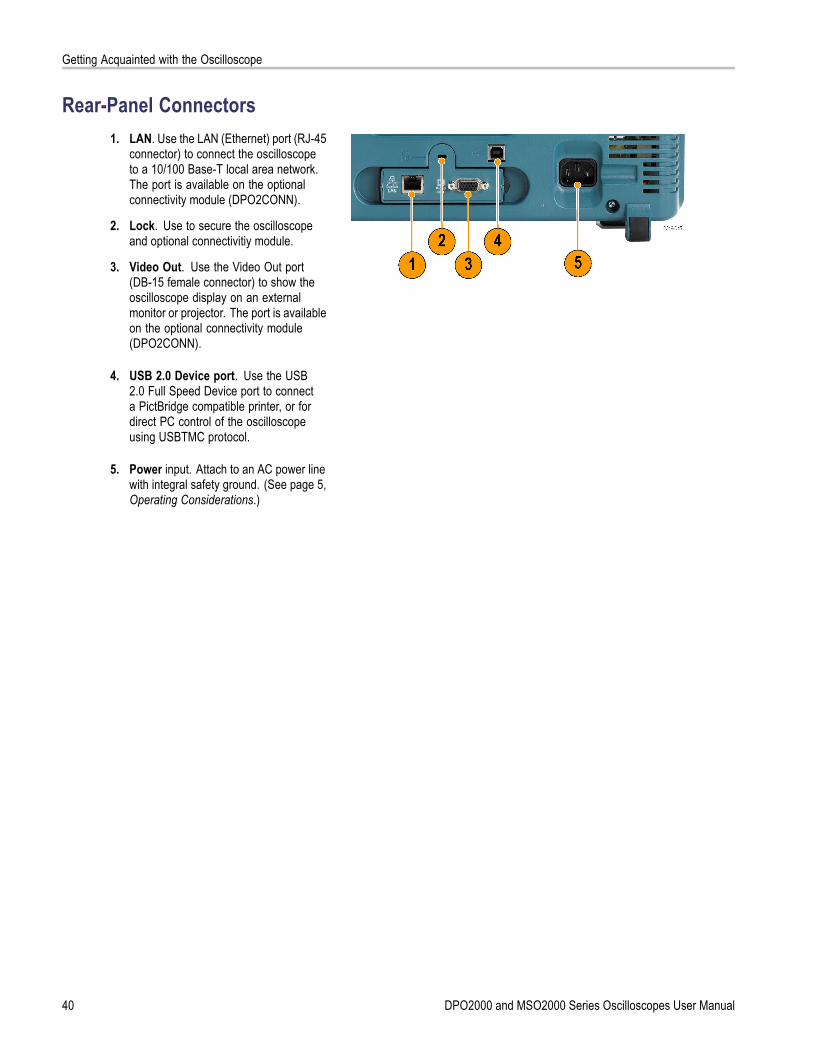
Rear-Panel Connectors1. LAN. Use the LAN (Ethernet) port (RJ-45
connector) to connect the oscilloscopeto a 10/100 Base-T local area network.The port is available on the optionalconnectivity module (DPO2CONN).
2. Lock. Use to secure the oscilloscopeand optional connectivitiy module.
3. Video Out. Use the Video Out port(DB-15 female connector) to show theoscilloscope display on an externalmonitor or projector. The port is availableon the optional connectivity module(DPO2CONN).
4. USB 2.0 Device port. Use the USB2.0 Full Speed Device port to connecta PictBridge compatible printer, or fordirect PC control of the oscilloscopeusing USBTMC protocol.
5. Power input. Attach to an AC power linewith integral safety ground. (See page 5,Operating Considerations.)
40 DPO2000 and MSO2000 Series Oscilloscopes User Manual

Acquire the Signal
Acquire the SignalThis section describes concepts of and procedures for setting up the oscilloscope to acquire the signal as you want it to.
Setting Up Analog ChannelsUse front-panel buttons and knobs to set up your oscilloscope to acquire signals using the analog channels.
1. Connect a P2221 probe or a TekVPIprobe to the input signal source.
2. Push Default Setup.
NOTE. If you are using a probe that does notsupply probe encoding, set the attenuation(probe factor) on the oscilloscope verticalmenu to match the probe. The defaultattenuation for the oscilloscope is 10X and isset in the Probe Setup lower-bezel menu ofany analog channel.
3. Select the input channel by pushing thefront-panel buttons.
4. Push Autoset.
DPO2000 and MSO2000 Series Oscilloscopes User Manual 41
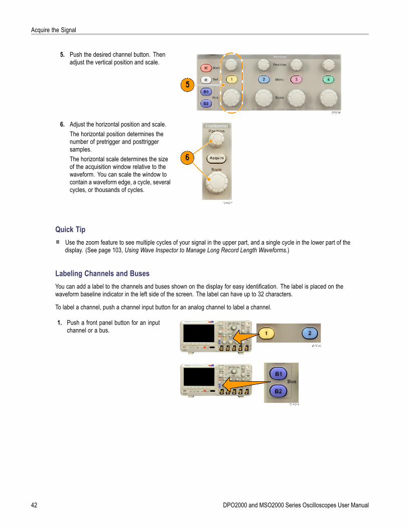
Acquire the Signal
5. Push the desired channel button. Thenadjust the vertical position and scale.
6. Adjust the horizontal position and scale.The horizontal position determines thenumber of pretrigger and posttriggersamples.The horizontal scale determines the sizeof the acquisition window relative to thewaveform. You can scale the window tocontain a waveform edge, a cycle, severalcycles, or thousands of cycles.
Quick TipUse the zoom feature to see multiple cycles of your signal in the upper part, and a single cycle in the lower part of thedisplay. (See page 103, Using Wave Inspector to Manage Long Record Length Waveforms.)
Labeling Channels and BusesYou can add a label to the channels and buses shown on the display for easy identification. The label is placed on thewaveform baseline indicator in the left side of the screen. The label can have up to 32 characters.
To label a channel, push a channel input button for an analog channel to label a channel.
1. Push a front panel button for an inputchannel or a bus.
42 DPO2000 and MSO2000 Series Oscilloscopes User Manual
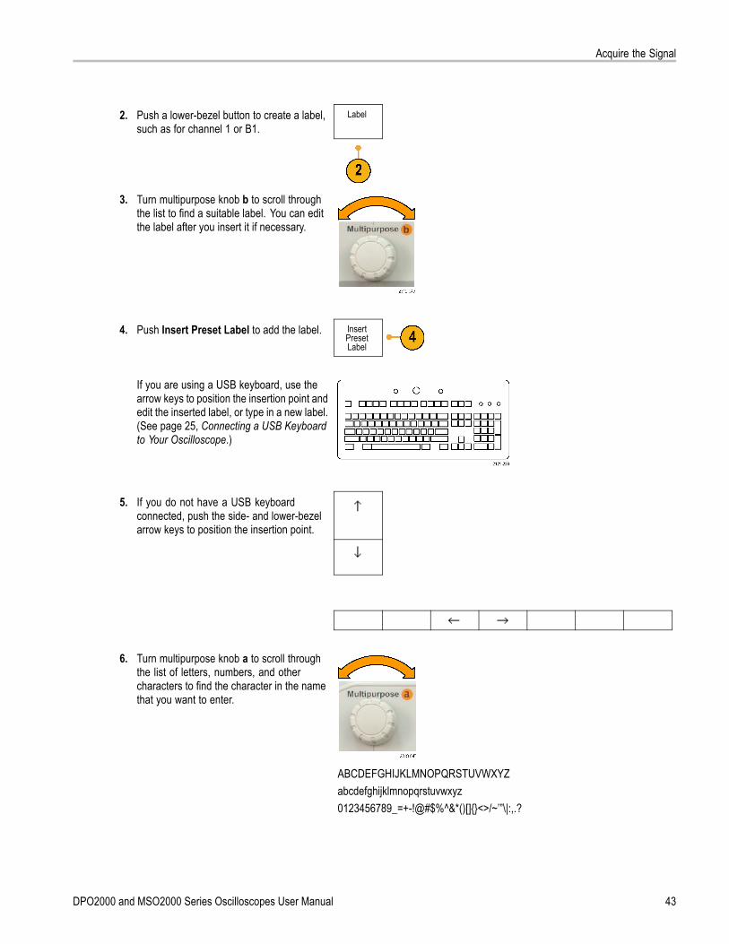
Acquire the Signal
2. Push a lower-bezel button to create a label,such as for channel 1 or B1.
Label
3. Turn multipurpose knob b to scroll throughthe list to find a suitable label. You can editthe label after you insert it if necessary.
4. Push Insert Preset Label to add the label. InsertPresetLabel
If you are using a USB keyboard, use thearrow keys to position the insertion point andedit the inserted label, or type in a new label.(See page 25, Connecting a USB Keyboardto Your Oscilloscope.)
5. If you do not have a USB keyboardconnected, push the side- and lower-bezelarrow keys to position the insertion point.
6. Turn multipurpose knob a to scroll throughthe list of letters, numbers, and othercharacters to find the character in the namethat you want to enter.
ABCDEFGHIJKLMNOPQRSTUVWXYZabcdefghijklmnopqrstuvwxyz0123456789_=+-!@#$%^&*()[]<>/~’”\|:,.?
DPO2000 and MSO2000 Series Oscilloscopes User Manual 43
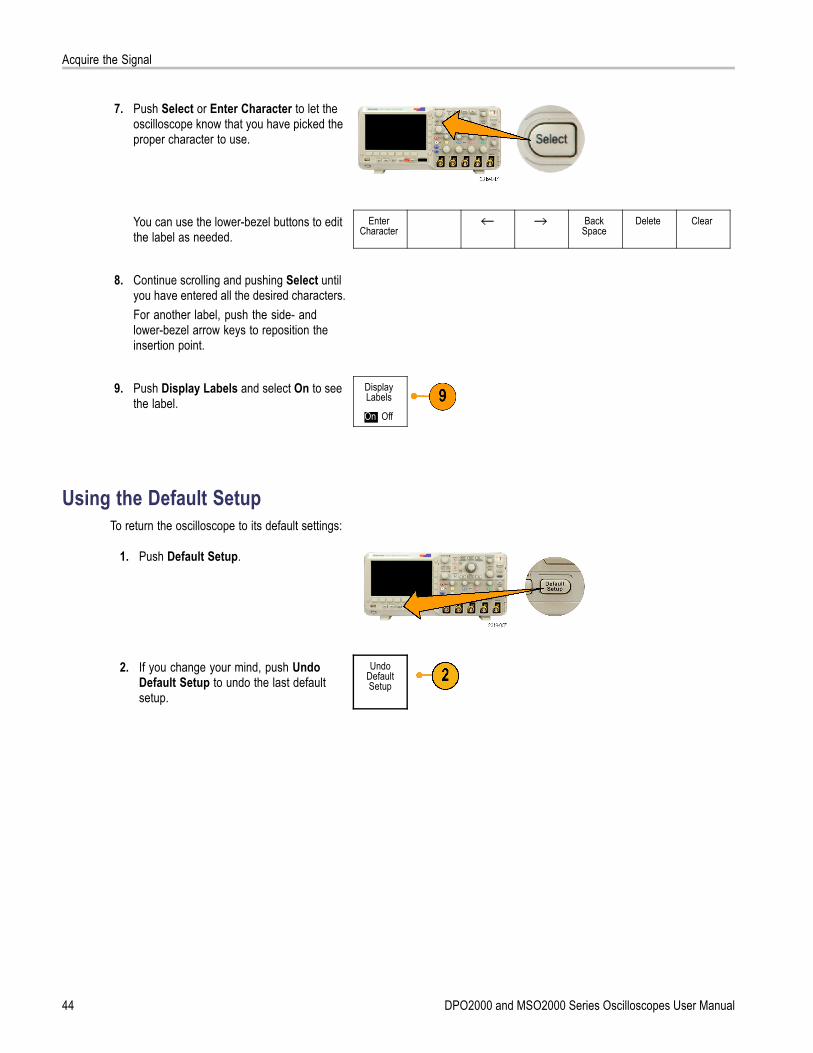
Acquire the Signal
7. Push Select or Enter Character to let theoscilloscope know that you have picked theproper character to use.
You can use the lower-bezel buttons to editthe label as needed.
EnterCharacter
BackSpace
Delete Clear
8. Continue scrolling and pushing Select untilyou have entered all the desired characters.For another label, push the side- andlower-bezel arrow keys to reposition theinsertion point.
9. Push Display Labels and select On to seethe label.
DisplayLabels
On| Off
Using the Default SetupTo return the oscilloscope to its default settings:
1. Push Default Setup.
2. If you change your mind, push UndoDefault Setup to undo the last defaultsetup.
UndoDefaultSetup
44 DPO2000 and MSO2000 Series Oscilloscopes User Manual
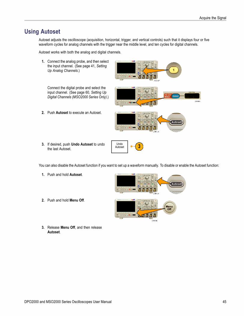
Acquire the Signal
Using AutosetAutoset adjusts the oscilloscope (acquisition, horizontal, trigger, and vertical controls) such that it displays four or fivewaveform cycles for analog channels with the trigger near the middle level, and ten cycles for digital channels.
Autoset works with both the analog and digital channels.
1. Connect the analog probe, and then selectthe input channel. (See page 41, SettingUp Analog Channels.)
Connect the digital probe and select theinput channel. (See page 60, Setting UpDigital Channels (MSO2000 Series Only).)
2. Push Autoset to execute an Autoset.
3. If desired, push Undo Autoset to undothe last Autoset.
UndoAutoset
You can also disable the Autoset function if you want to set up a waveform manually. To disable or enable the Autoset function:
1. Push and hold Autoset.
2. Push and hold Menu Off.
3. Release Menu Off, and then releaseAutoset.
DPO2000 and MSO2000 Series Oscilloscopes User Manual 45

Acquire the Signal
4. Select the desired side-bezel setting. AutosetEnabled
AutosetDisabled
Quick TipsTo position the waveform appropriately, Autoset may change the vertical position. Autoset always sets vertical offsetto 0 V.
If you use Autoset when no channels are displayed, the oscilloscope turns on channel one (1) and scales it.
If you use Autoset and the oscilloscope detects a video signal, the oscilloscope automatically sets the trigger type tovideo and makes other adjustments to display a stable video signal.
To manually set the oscilloscope to view a video signal in an IRE graticule:1. Set the Trigger Type to Video.2. Set the Vertical Scale to 143mV/div.3. Select the proper input channel Attenuation for the probe or cable being used to feed the video signal to theoscilloscope.4. If necessary, connect a 75 ohm pass-through terminator to the oscilloscope input. For example, you need to add aterminator when you use a 75-ohm cable between the video signal and the oscilloscope.
Acquisition ConceptsBefore a signal can be displayed, it must pass through the input channel where it is scaled and digitized. Each channelhas a dedicated input amplifier and digitizer. Each channel produces a stream of digital data from which the oscilloscopeextracts waveform records.
Sampling Process
Acquisition is the process of sampling ananalog signal, converting it into digitaldata, and assembling it into a waveformrecord, which is then stored in acquisitionmemory. Input signal Sampled points
Digital values
46 DPO2000 and MSO2000 Series Oscilloscopes User Manual
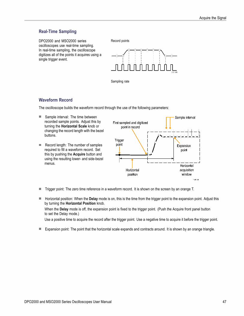
Acquire the Signal
Real-Time Sampling
Record pointsDPO2000 and MSO2000 seriesoscilloscopes use real-time sampling.In real-time sampling, the oscilloscopedigitizes all of the points it acquires using asingle trigger event.
Sampling rate
Waveform RecordThe oscilloscope builds the waveform record through the use of the following parameters:
Sample interval: The time betweenrecorded sample points. Adjust this byturning the Horizontal Scale knob orchanging the record length with the bezelbuttons.
Record length: The number of samplesrequired to fill a waveform record. Setthis by pushing the Acquire button andusing the resulting lower- and side-bezelmenus.
Trigger point: The zero time reference in a waveform record. It is shown on the screen by an orange T.
Horizontal position: When the Delay mode is on, this is the time from the trigger point to the expansion point. Adjust thisby turning the Horizontal Position knob.When the Delay mode is off, the expansion point is fixed to the trigger point. (Push the Acquire front panel buttonto set the Delay mode.)Use a positive time to acquire the record after the trigger point. Use a negative time to acquire it before the trigger point.
Expansion point: The point that the horizontal scale expands and contracts around. It is shown by an orange triangle.
DPO2000 and MSO2000 Series Oscilloscopes User Manual 47
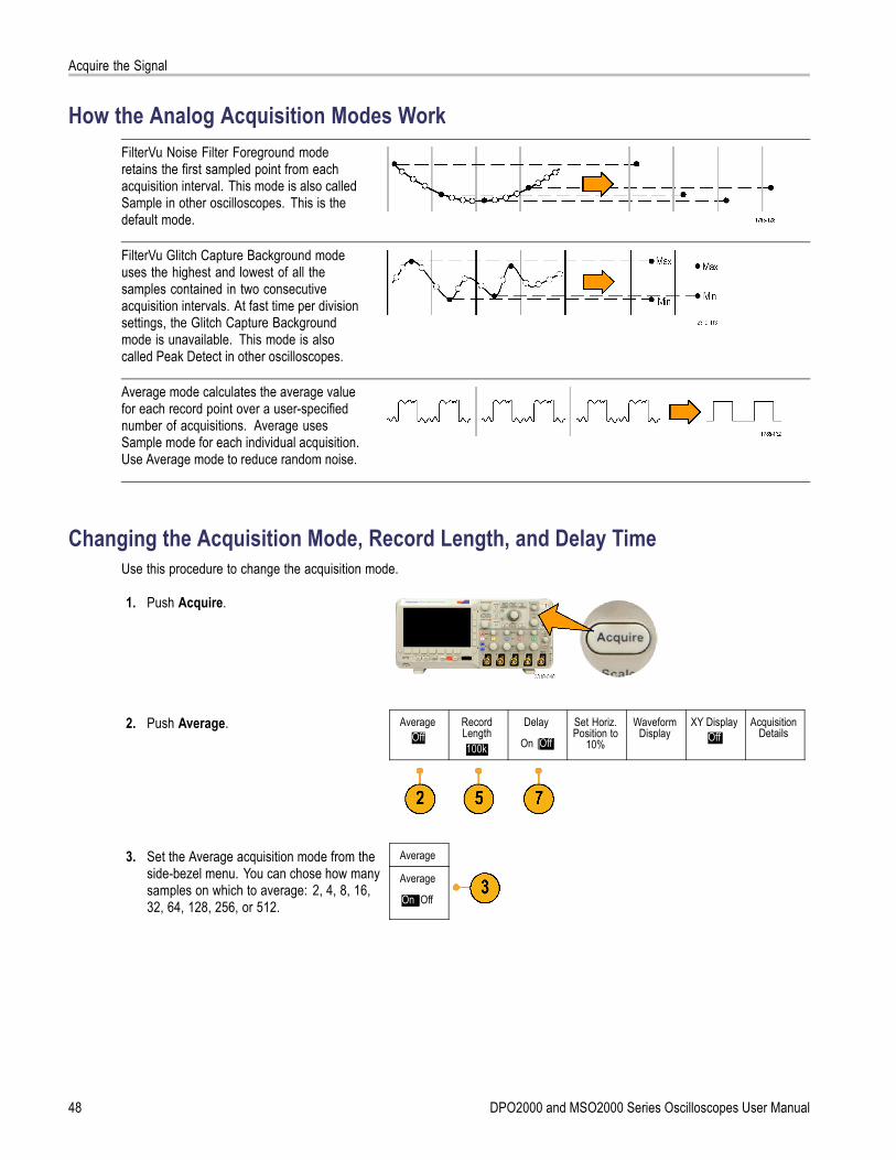
Acquire the Signal
How the Analog Acquisition Modes WorkFilterVu Noise Filter Foreground moderetains the first sampled point from eachacquisition interval. This mode is also calledSample in other oscilloscopes. This is thedefault mode.
FilterVu Glitch Capture Background modeuses the highest and lowest of all thesamples contained in two consecutiveacquisition intervals. At fast time per divisionsettings, the Glitch Capture Backgroundmode is unavailable. This mode is alsocalled Peak Detect in other oscilloscopes.
Average mode calculates the average valuefor each record point over a user-specifiednumber of acquisitions. Average usesSample mode for each individual acquisition.Use Average mode to reduce random noise.
Changing the Acquisition Mode, Record Length, and Delay TimeUse this procedure to change the acquisition mode.
1. Push Acquire.
2. Push Average. AverageOff
RecordLength100k
Delay
On |Off
Set Horiz.Position to
10%
WaveformDisplay
XY DisplayOff
AcquisitionDetails
Average3. Set the Average acquisition mode from theside-bezel menu. You can chose how manysamples on which to average: 2, 4, 8, 16,32, 64, 128, 256, or 512.
Average
On |Off
48 DPO2000 and MSO2000 Series Oscilloscopes User Manual
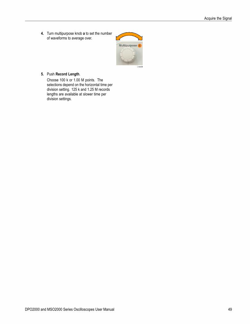
Acquire the Signal
4. Turn multipurpose knob a to set the numberof waveforms to average over.
5. Push Record Length.Choose 100 k or 1.00 M points. Theselections depend on the horizontal time perdivision setting. 125 k and 1.25 M recordslengths are available at slower time perdivision settings.
DPO2000 and MSO2000 Series Oscilloscopes User Manual 49
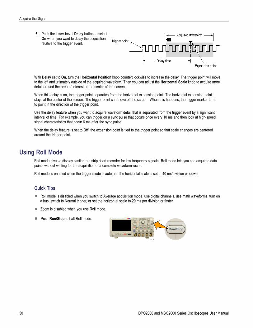
Acquire the Signal
6. Push the lower-bezel Delay button to selectOn when you want to delay the acquisitionrelative to the trigger event.
With Delay set to On, turn the Horizontal Position knob counterclockwise to increase the delay. The trigger point will moveto the left and ultimately outside of the acquired waveform. Then you can adjust the Horizontal Scale knob to acquire moredetail around the area of interest at the center of the screen.
When this delay is on, the trigger point separates from the horizontal expansion point. The horizontal expansion pointstays at the center of the screen. The trigger point can move off the screen. When this happens, the trigger marker turnsto point in the direction of the trigger point.
Use the delay feature when you want to acquire waveform detail that is separated from the trigger event by a significantinterval of time. For example, you can trigger on a sync pulse that occurs once every 10 ms and then look at high-speedsignal characteristics that occur 6 ms after the sync pulse.
When the delay feature is set to Off, the expansion point is tied to the trigger point so that scale changes are centeredaround the trigger point.
Using Roll ModeRoll mode gives a display similar to a strip chart recorder for low-frequency signals. Roll mode lets you see acquired datapoints without waiting for the acquisition of a complete waveform record.
Roll mode is enabled when the trigger mode is auto and the horizontal scale is set to 40 ms/division or slower.
Quick TipsRoll mode is disabled when you switch to Average acquisition mode, use digital channels, use math waveforms, turn ona bus, switch to Normal trigger, or set the horizontal scale to 20 ms per division or faster.
Zoom is disabled when you use Roll mode.
Push Run/Stop to halt Roll mode.
50 DPO2000 and MSO2000 Series Oscilloscopes User Manual

Acquire the Signal
Setting Up a Serial or Parallel BusYour oscilloscope can decode and trigger on:
I2C and SPI serial buses if the DPO2EMBD application module is installed
CAN and LIN serial buses if the DPO2AUTO application module is installed
RS-232, RS-422, RS-485, and UART serial buses if the DPO2COMP application module is installed
Parallel buses if you are using an MSO2000 series oscilloscope
(See page 14, Application Module Free Trial.)
Using Buses in Two StepsTo quickly use serial bus triggering:
1. Push B1 or B2 and enter parameters ofthe bus to trigger on.You can separately use B1 and B2 toview two different buses.
2. Push Trigger Menu and enter triggerparameters. (See page 68, Choosing aTrigger Type.)You can display bus information withouttriggering on the bus signal.
Setting Up Bus Parameters
NOTE. For all serial bus sources, use any combination of channels 1 through 4, and D15 through D0.
To trigger on serial or parallel bus conditions, refer to Triggering on Buses. (See page 70, Triggering on Buses.)
DPO2000 and MSO2000 Series Oscilloscopes User Manual 51

Acquire the Signal
To set up bus parameters:
1. Push B1 or B2 to bring up the lower-bezelbus menu.
2. Push Bus. Turn multipurpose knob a to scrollthrough the list of bus types and select thedesired bus: Parallel (MSO2000 series only),I2C, SPI, CAN, RS-232, or LIN.
B1Parallel
DefineInputs
Thresholds B1 LabelParallel
BusDisplay
EventTable
The actual menu items shown will depend onyour model oscilloscope and the applicationmodules installed.
3. Push Define Inputs. The choices dependon the selected bus.
Use the side-bezel buttons to defineparameters for the inputs, such as specificsignals to an analog or digital channel.
DefineInputs
If you select Parallel, push the side-bezelbutton to enable or disable Clocked Data.
ClockedData
Yes|No
Push the side-bezel button to select theClock Edge on which to clock data: risingedge, falling edge, or both edges.
ClockEdge
Turn multipurpose knob a to select theNumber of Data Bits in the parallel bus.
Number ofData Bits
(a) 16
Turn multipurpose knob a to select thedesired bit to define.Turn multipurpose knob b to select thedesired analog or digital channel as thesource for the bit.
Define Bits(a) Bit 15(b) D15
52 DPO2000 and MSO2000 Series Oscilloscopes User Manual
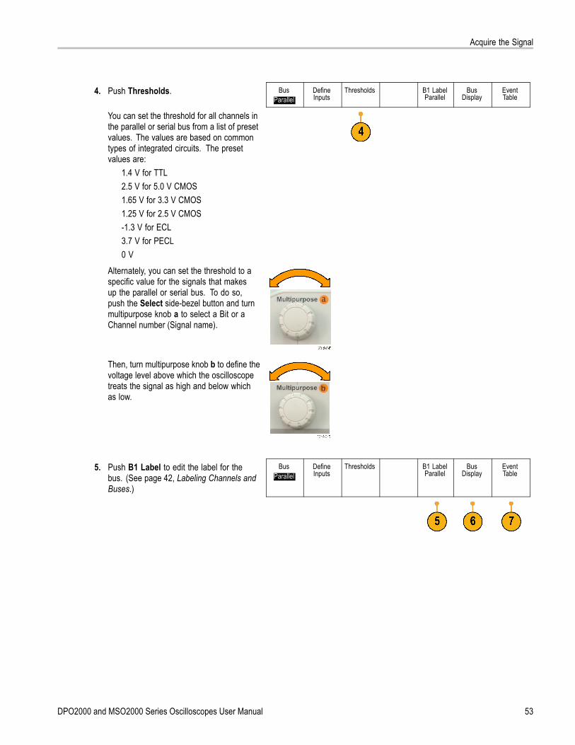
Acquire the Signal
4. Push Thresholds. BusParallel
DefineInputs
Thresholds B1 LabelParallel
BusDisplay
EventTable
You can set the threshold for all channels inthe parallel or serial bus from a list of presetvalues. The values are based on commontypes of integrated circuits. The presetvalues are:
1.4 V for TTL2.5 V for 5.0 V CMOS1.65 V for 3.3 V CMOS1.25 V for 2.5 V CMOS-1.3 V for ECL3.7 V for PECL0 V
Alternately, you can set the threshold to aspecific value for the signals that makesup the parallel or serial bus. To do so,push the Select side-bezel button and turnmultipurpose knob a to select a Bit or aChannel number (Signal name).
Then, turn multipurpose knob b to define thevoltage level above which the oscilloscopetreats the signal as high and below whichas low.
5. Push B1 Label to edit the label for thebus. (See page 42, Labeling Channels andBuses.)
BusParallel
DefineInputs
Thresholds B1 LabelParallel
BusDisplay
EventTable
DPO2000 and MSO2000 Series Oscilloscopes User Manual 53
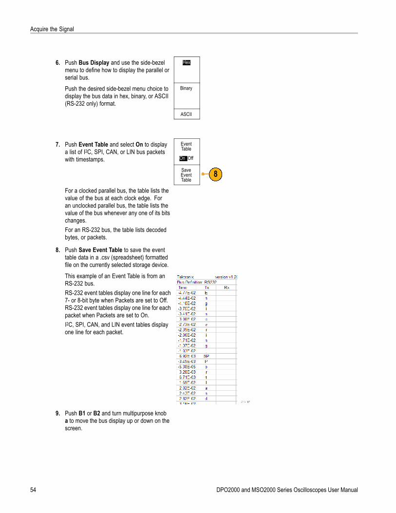
Acquire the Signal
6. Push Bus Display and use the side-bezelmenu to define how to display the parallel orserial bus.
Hex
Push the desired side-bezel menu choice todisplay the bus data in hex, binary, or ASCII(RS-232 only) format.
Binary
ASCII
7. Push Event Table and select On to displaya list of I2C, SPI, CAN, or LIN bus packetswith timestamps.
EventTable
On |Off
SaveEventTable
For a clocked parallel bus, the table lists thevalue of the bus at each clock edge. Foran unclocked parallel bus, the table lists thevalue of the bus whenever any one of its bitschanges.For an RS-232 bus, the table lists decodedbytes, or packets.
8. Push Save Event Table to save the eventtable data in a .csv (spreadsheet) formattedfile on the currently selected storage device.
This example of an Event Table is from anRS-232 bus.RS-232 event tables display one line for each7- or 8-bit byte when Packets are set to Off.RS-232 event tables display one line for eachpacket when Packets are set to On.I2C, SPI, CAN, and LIN event tables displayone line for each packet.
9. Push B1 or B2 and turn multipurpose knoba to move the bus display up or down on thescreen.
54 DPO2000 and MSO2000 Series Oscilloscopes User Manual
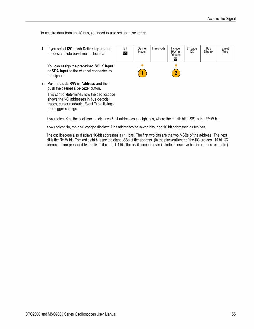
Acquire the Signal
To acquire data from an I2C bus, you need to also set up these items:
1. If you select I2C, push Define Inputs andthe desired side-bezel menu choices.
B1I2C
DefineInputs
Thresholds IncludeR/W inAddress
No
B1 LabelI2C
BusDisplay
EventTable
You can assign the predefined SCLK Inputor SDA Input to the channel connected tothe signal.
2. Push Include R/W in Address and thenpush the desired side-bezel button.This control determines how the oscilloscopeshows the I2C addresses in bus decodetraces, cursor readouts, Event Table listings,and trigger settings.
If you select Yes, the oscilloscope displays 7-bit addresses as eight bits, where the eighth bit (LSB) is the R/~W bit.
If you select No, the oscilloscope displays 7-bit addresses as seven bits, and 10-bit addresses as ten bits.
The oscilloscope also displays 10-bit addresses as 11 bits. The first two bits are the two MSBs of the address. The nextbit is the R/~W bit. The last eight bits are the eight LSBs of the address. (In the physical layer of the I2C protocol, 10 bit I2Caddresses are preceded by the five bit code, 11110. The oscilloscope never includes these five bits in address readouts.)
DPO2000 and MSO2000 Series Oscilloscopes User Manual 55
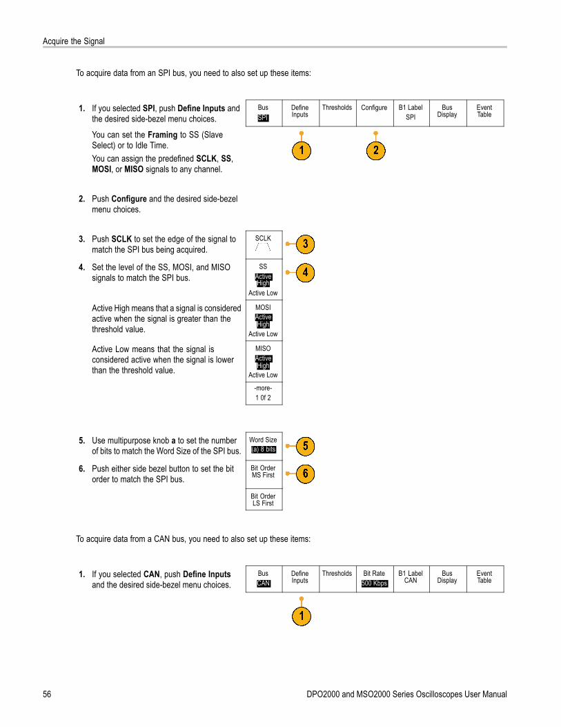
Acquire the Signal
To acquire data from an SPI bus, you need to also set up these items:
1. If you selected SPI, push Define Inputs andthe desired side-bezel menu choices.
BusSPI
DefineInputs
Thresholds Configure B1 LabelSPI
BusDisplay
EventTable
You can set the Framing to SS (SlaveSelect) or to Idle Time.You can assign the predefined SCLK, SS,MOSI, or MISO signals to any channel.
2. Push Configure and the desired side-bezelmenu choices.
3. Push SCLK to set the edge of the signal tomatch the SPI bus being acquired.
SCLK
4. Set the level of the SS, MOSI, and MISOsignals to match the SPI bus.
SSActiveHigh
Active Low
Active High means that a signal is consideredactive when the signal is greater than thethreshold value.
MOSIActiveHigh
Active Low
Active Low means that the signal isconsidered active when the signal is lowerthan the threshold value.
MISOActiveHigh
Active Low
-more-1 0f 2
5. Use multipurpose knob a to set the numberof bits to match the Word Size of the SPI bus.
Word Size(a) 8 bits
6. Push either side bezel button to set the bitorder to match the SPI bus.
Bit OrderMS First
Bit OrderLS First
To acquire data from a CAN bus, you need to also set up these items:
1. If you selected CAN, push Define Inputsand the desired side-bezel menu choices.
BusCAN
DefineInputs
Thresholds Bit Rate500 Kbps
B1 LabelCAN
BusDisplay
EventTable
56 DPO2000 and MSO2000 Series Oscilloscopes User Manual
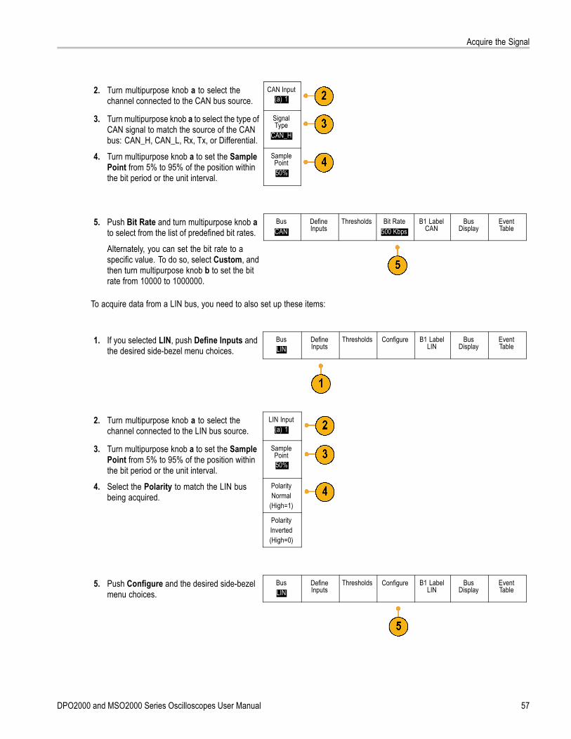
Acquire the Signal
2. Turn multipurpose knob a to select thechannel connected to the CAN bus source.
CAN Input(a) 1
3. Turn multipurpose knob a to select the type ofCAN signal to match the source of the CANbus: CAN_H, CAN_L, Rx, Tx, or Differential.
SignalType
CAN_H
4. Turn multipurpose knob a to set the SamplePoint from 5% to 95% of the position withinthe bit period or the unit interval.
SamplePoint50%
5. Push Bit Rate and turn multipurpose knob ato select from the list of predefined bit rates.
BusCAN
DefineInputs
Thresholds Bit Rate500 Kbps
B1 LabelCAN
BusDisplay
EventTable
Alternately, you can set the bit rate to aspecific value. To do so, select Custom, andthen turn multipurpose knob b to set the bitrate from 10000 to 1000000.
To acquire data from a LIN bus, you need to also set up these items:
1. If you selected LIN, push Define Inputs andthe desired side-bezel menu choices.
BusLIN
DefineInputs
Thresholds Configure B1 LabelLIN
BusDisplay
EventTable
2. Turn multipurpose knob a to select thechannel connected to the LIN bus source.
LIN Input(a) 1
3. Turn multipurpose knob a to set the SamplePoint from 5% to 95% of the position withinthe bit period or the unit interval.
SamplePoint50%
4. Select the Polarity to match the LIN busbeing acquired.
PolarityNormal
(High=1)
PolarityInverted(High=0)
5. Push Configure and the desired side-bezelmenu choices.
BusLIN
DefineInputs
Thresholds Configure B1 LabelLIN
BusDisplay
EventTable
DPO2000 and MSO2000 Series Oscilloscopes User Manual 57

Acquire the Signal
6. Push Bit Rate, and turn multipurpose knob ato select from the list of predefined bit rates.Alternately, you can set the bit rate to aspecific value. To do so, select Custom, andthen turn multipurpose knob b to set the bitrate from 800 bps to 100000 bps.
Bit Rate(a)
19.2K bps
7. Push LIN Standard, and turn multipurposeknob a to select the appropriate standard.
LINStandard
v1.x
8. Push Include Parity Bits with Id to selectwhether or not to include parity bits.
IncludeParity Bits
with Id
On|Off
To acquire data from a RS-232 bus, you need to also set up these items:
1. If you selected RS-232, push Configure andthe desired side-bezel menu choices.
BusRS-232
DefineInputs
Thresholds Configure9600-8-N
B1 LabelRS-232
BusDisplay
EventTable
Use the side-bezel menu to configure thebus. Use Normal polarity to trigger onRS-232 signals and Inverted polarity totrigger on RS-422, RS-485, and UARTsignals.
58 DPO2000 and MSO2000 Series Oscilloscopes User Manual
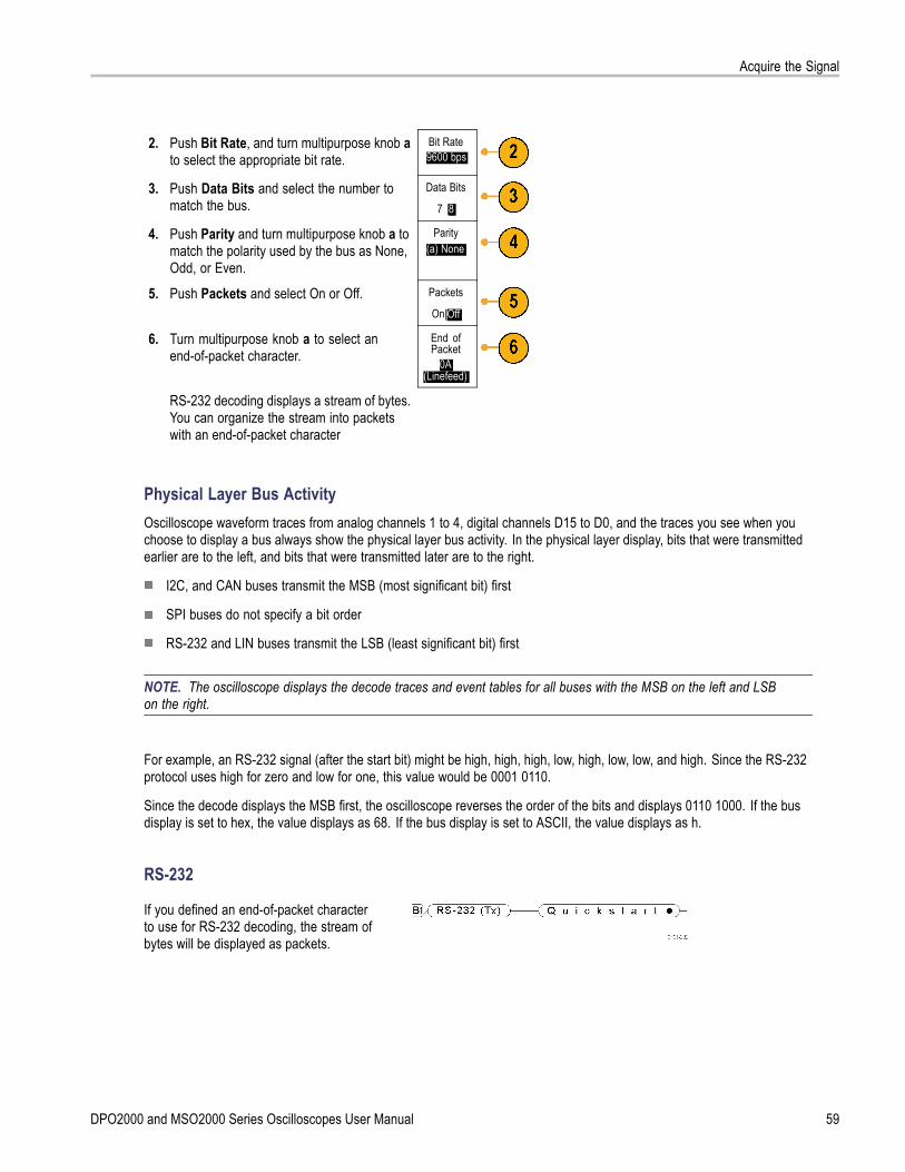
Acquire the Signal
2. Push Bit Rate, and turn multipurpose knob ato select the appropriate bit rate.
Bit Rate9600 bps
3. Push Data Bits and select the number tomatch the bus.
Data Bits
7 |8
4. Push Parity and turn multipurpose knob a tomatch the polarity used by the bus as None,Odd, or Even.
Parity(a) None
5. Push Packets and select On or Off. Packets
On|Off
6. Turn multipurpose knob a to select anend-of-packet character.
End ofPacket
0A(Linefeed)
RS-232 decoding displays a stream of bytes.You can organize the stream into packetswith an end-of-packet character
Physical Layer Bus ActivityOscilloscope waveform traces from analog channels 1 to 4, digital channels D15 to D0, and the traces you see when youchoose to display a bus always show the physical layer bus activity. In the physical layer display, bits that were transmittedearlier are to the left, and bits that were transmitted later are to the right.
I2C, and CAN buses transmit the MSB (most significant bit) first
SPI buses do not specify a bit order
RS-232 and LIN buses transmit the LSB (least significant bit) first
NOTE. The oscilloscope displays the decode traces and event tables for all buses with the MSB on the left and LSBon the right.
For example, an RS-232 signal (after the start bit) might be high, high, high, low, high, low, low, and high. Since the RS-232protocol uses high for zero and low for one, this value would be 0001 0110.
Since the decode displays the MSB first, the oscilloscope reverses the order of the bits and displays 0110 1000. If the busdisplay is set to hex, the value displays as 68. If the bus display is set to ASCII, the value displays as h.
RS-232
If you defined an end-of-packet characterto use for RS-232 decoding, the stream ofbytes will be displayed as packets.
DPO2000 and MSO2000 Series Oscilloscopes User Manual 59
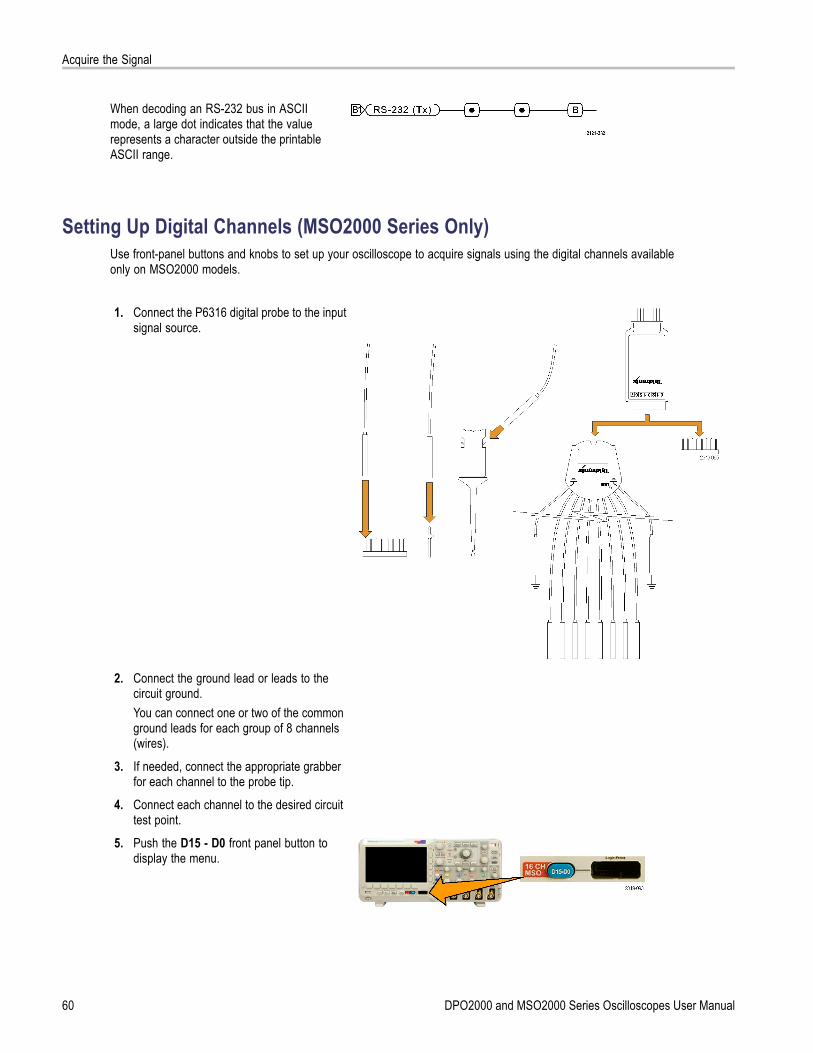
Acquire the Signal
When decoding an RS-232 bus in ASCIImode, a large dot indicates that the valuerepresents a character outside the printableASCII range.
Setting Up Digital Channels (MSO2000 Series Only)Use front-panel buttons and knobs to set up your oscilloscope to acquire signals using the digital channels availableonly on MSO2000 models.
1. Connect the P6316 digital probe to the inputsignal source.
2. Connect the ground lead or leads to thecircuit ground.You can connect one or two of the commonground leads for each group of 8 channels(wires).
3. If needed, connect the appropriate grabberfor each channel to the probe tip.
4. Connect each channel to the desired circuittest point.
5. Push the D15 - D0 front panel button todisplay the menu.
60 DPO2000 and MSO2000 Series Oscilloscopes User Manual
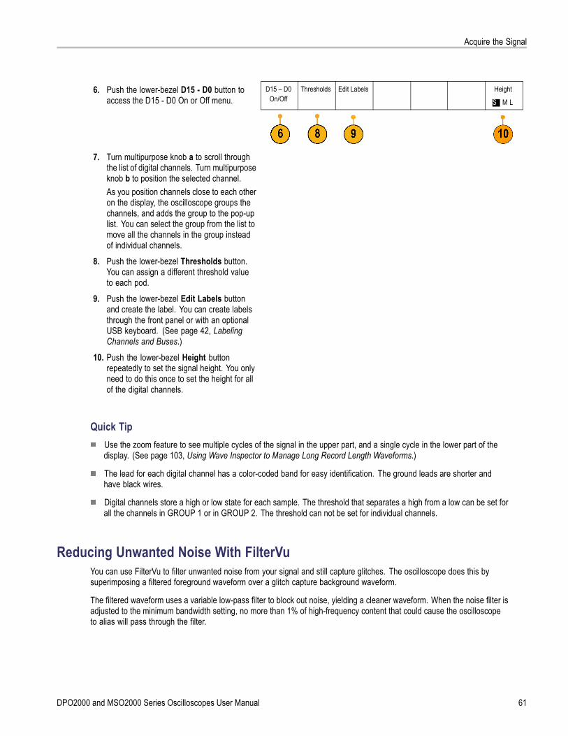
Acquire the Signal
6. Push the lower-bezel D15 - D0 button toaccess the D15 - D0 On or Off menu.
D15 – D0On/Off
Thresholds Edit Labels Height
S | M L
7. Turn multipurpose knob a to scroll throughthe list of digital channels. Turn multipurposeknob b to position the selected channel.As you position channels close to each otheron the display, the oscilloscope groups thechannels, and adds the group to the pop-uplist. You can select the group from the list tomove all the channels in the group insteadof individual channels.
8. Push the lower-bezel Thresholds button.You can assign a different threshold valueto each pod.
9. Push the lower-bezel Edit Labels buttonand create the label. You can create labelsthrough the front panel or with an optionalUSB keyboard. (See page 42, LabelingChannels and Buses.)
10. Push the lower-bezel Height buttonrepeatedly to set the signal height. You onlyneed to do this once to set the height for allof the digital channels.
Quick TipUse the zoom feature to see multiple cycles of the signal in the upper part, and a single cycle in the lower part of thedisplay. (See page 103, Using Wave Inspector to Manage Long Record Length Waveforms.)
The lead for each digital channel has a color-coded band for easy identification. The ground leads are shorter andhave black wires.
Digital channels store a high or low state for each sample. The threshold that separates a high from a low can be set forall the channels in GROUP 1 or in GROUP 2. The threshold can not be set for individual channels.
Reducing Unwanted Noise With FilterVuYou can use FilterVu to filter unwanted noise from your signal and still capture glitches. The oscilloscope does this bysuperimposing a filtered foreground waveform over a glitch capture background waveform.
The filtered waveform uses a variable low-pass filter to block out noise, yielding a cleaner waveform. When the noise filter isadjusted to the minimum bandwidth setting, no more than 1% of high-frequency content that could cause the oscilloscopeto alias will pass through the filter.
DPO2000 and MSO2000 Series Oscilloscopes User Manual 61

Acquire the Signal
The glitch capture waveform shows signal details up to the full bandwidth of the oscilloscope. The oscilloscope capturespulses as narrow as 5 ns, using peak detect min/max sampling.
When your signal is filtered, the glitch capture waveform changes color to distinguish it from the filtered waveform. Whenthe signal is filtered, you can independently adjust the intensity of the glitch capture waveform. When the signal is notfiltered, the intensity of the glitch capture waveform depends on the overall intensity (under the Intensity button on theoscilloscope front panel).
FilterVu, Bandwidth Limit, and AveragingYou can use FilterVu, Bandwidth Limits, or Average mode to reduce noise in your signal. Each has benefits.
NOTE. FilterVu does not apply to triggering. To reduce the effects of noise on your signal while triggering, use BandwidthLimits or use Coupling settings.
Use FilterVu when you want to do the following:
Adjust your filter frequency with more granularity than the Bandwidth Limit provides.
Adjust all channels to the same frequency.
Acquire a non-repetitive or a single-shot signal.
Use Bandwidth Limit when you want to do the following:
Filter only one channel.
Trigger on a filtered signal.
Acquire a non-repetitive or a single-shot signal.
Use Average mode when you want to do the following:
Acquire a repetitive signal.
Noise on your signal is random (not correlated with the trigger).
Increase the vertical precision of your acquisition.
NOTE. You can use FilterVu with Bandwidth Limit. You cannot use FilterVu with Average mode.
Quick TipsYou can choose to save to a file with full resolution (every point that was captured) or reduced resolution (fewer points).When your signal is filtered, only the reduced-resolution waveform is guaranteed to be filtered to the chosen frequency.Sometimes, the filter is unable to produce a full-resolution waveform with a frequency as low as the chosen frequency.The frequency of the full-resolution waveform is shown in the saved file.
When the glitch capture background is on, a saved waveform file includes both the foreground and the background data.
Reference waveforms can be filtered; the chosen noise filter frequency also applies to references. Reference waveformsalso have a glitch capture background.
Reference waveforms are always saved at full resolution. Unlike saving a waveform to a file, there is no reducedresolution option.
62 DPO2000 and MSO2000 Series Oscilloscopes User Manual

Acquire the Signal
When the signal is not filtered, most measurements are taken on the foreground waveform. The min, max, andpeak-to-peak measurements are taken on the glitch capture background, because they measure the smallest andlargest amplitudes in the waveform.
When the signal is filtered, all measurements are taken from the filtered waveform.
Dual-waveform math can be filtered; the chosen noise filter frequency also applies to math. Dual-waveform mathdoes not have a glitch capture background.
Search uses the glitch capture background, when available. This lets you better search for spikes and other anomalies.
Serial bus decode uses a full-resolution sample (foreground) waveform. When filtering is active, that waveform might notbe filtered to the chosen frequency.
Using FilterVuBy default, the noise filter cutoff frequency is set to the full bandwidth of the oscilloscope when you use FilterVu. To invokethe variable low-pass filter (noise filter), turn the multipurpose knob counterclockwise. The oscilloscope passes lowerfrequency signals which results in a cleaner-looking waveform. The noise frequency readout displays frequencies thatthe oscilloscope includes in the foreground waveform. The oscilloscope displays higher frequency components in thebackground waveform, up to the bandwidth of the DPO2000 or MSO2000 model.
NOTE. The oscilloscope always displays the noise filter cutoff frequency in the upper right part of the screen. The cutofffrequency reflects the -3 dB point.
1. Push the FilterVu button.
2. Turn multipurpose knob a to adjust theNoise Filter (Foreground) value.
DPO2000 and MSO2000 Series Oscilloscopes User Manual 63

Acquire the Signal
Noise Fil-ter (Fore-ground)
(a)200MHz
3. Push Glitch Capture Background to turnoff the background waveform that containsthe higher frequency components of thesignal.With Glitch Capture set to Off, theoscilloscope displays only the noise filter(foreground) waveform.
GlitchCaptureBack-ground
On |Off
4. With Glitch Capture set to On, turnmultipurpose knob b to adjust the intensity ofthe Glitch Capture (background) waveform.You can only adjust the intensity whenfiltering.
Back-ground
IntensityAuto
64 DPO2000 and MSO2000 Series Oscilloscopes User Manual
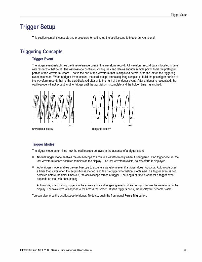
Trigger Setup
Trigger SetupThis section contains concepts and procedures for setting up the oscilloscope to trigger on your signal.
Triggering ConceptsTrigger EventThe trigger event establishes the time-reference point in the waveform record. All waveform record data is located in timewith respect to that point. The oscilloscope continuously acquires and retains enough sample points to fill the pretriggerportion of the waveform record. That is the part of the waveform that is displayed before, or to the left of, the triggeringevent on screen. When a trigger event occurs, the oscilloscope starts acquiring samples to build the posttrigger portion ofthe waveform record, that is, the part displayed after or to the right of the trigger event. After a trigger is recognized, theoscilloscope will not accept another trigger until the acquisition is complete and the holdoff time has expired.
Untriggered display Triggered display
Trigger ModesThe trigger mode determines how the oscilloscope behaves in the absence of a trigger event:
Normal trigger mode enables the oscilloscope to acquire a waveform only when it is triggered. If no trigger occurs, thelast waveform record acquired remains on the display. If no last waveform exists, no waveform is displayed.
Auto trigger mode enables the oscilloscope to acquire a waveform even if a trigger does not occur. Auto mode usesa timer that starts when the acquisition is started, and the pretrigger information is obtained. If a trigger event is notdetected before the timer times out, the oscilloscope forces a trigger. The length of time it waits for a trigger eventdepends on the time base setting.
Auto mode, when forcing triggers in the absence of valid triggering events, does not synchronize the waveform on thedisplay. The waveform will appear to roll across the screen. If valid triggers occur, the display will become stable.
You can also force the oscilloscope to trigger. To do so, push the front-panel Force Trig button.
DPO2000 and MSO2000 Series Oscilloscopes User Manual 65

Trigger Setup
Trigger Holdoff
Adjust holdoff to obtain stable triggeringwhen the oscilloscope is triggering onundesired trigger events.Trigger holdoff can help stabilize triggering,since the oscilloscope does not recognizenew triggers during the holdoff time. Whenthe oscilloscope recognizes a trigger event,it disables the trigger system until acquisitionis complete. In addition, the trigger systemremains disabled during the holdoff periodthat follows each acquisition.
Holdoffs
Trigger CouplingTrigger coupling determines what part of the signal is passed to the trigger circuit. Edge triggering can use all availablecoupling types: DC, Low Frequency Rejection, High Frequency Rejection, and Noise Rejection. All other trigger typesuse DC coupling only.
The cutoff frequency for low frequency rejection is 65 kHz. The cutoff frequency for high frequency rejection is 85 kHz.
Horizontal Position
When Delay Mode is on, use horizontalposition to acquire waveform detail in aregion that is separated from the triggerlocation by a significant interval of time.
66 DPO2000 and MSO2000 Series Oscilloscopes User Manual

Trigger Setup
1. Adjust the position (delay) time byrotating the Horizontal Position knob.
2. Turn the horizontal Scale knob to acquirethe detail that you need around theposition (delay) expansion point.
The part of the record that occurs before the trigger is the pretrigger portion. The part that occurs after the trigger is theposttrigger portion. Pretrigger data can help you troubleshoot. For example, to find the cause of an unwanted glitch inyour test circuit, you can trigger on the glitch and make the pretrigger period large enough to capture data before theglitch. By analyzing what happens before the glitch, you may uncover information that helps you find the source of theglitch. Alternatively, to see what is happening in your system as a result of the trigger event, make the posttrigger periodlarge enough to capture data after the trigger.
Slope and Level
The slope control determines whether theoscilloscope finds the trigger point on therising or the falling edge of a signal.The level control determines where on thatedge the trigger point occurs.
The oscilloscope provides a long horizontalbar or bars across the graticule to temporarilyshow the trigger level.
1. Turn the front-panel Trigger Level knobto adjust the trigger level without goingto a menu.
2. Push the Force Trig button to force theoscilloscope to trigger.
DPO2000 and MSO2000 Series Oscilloscopes User Manual 67
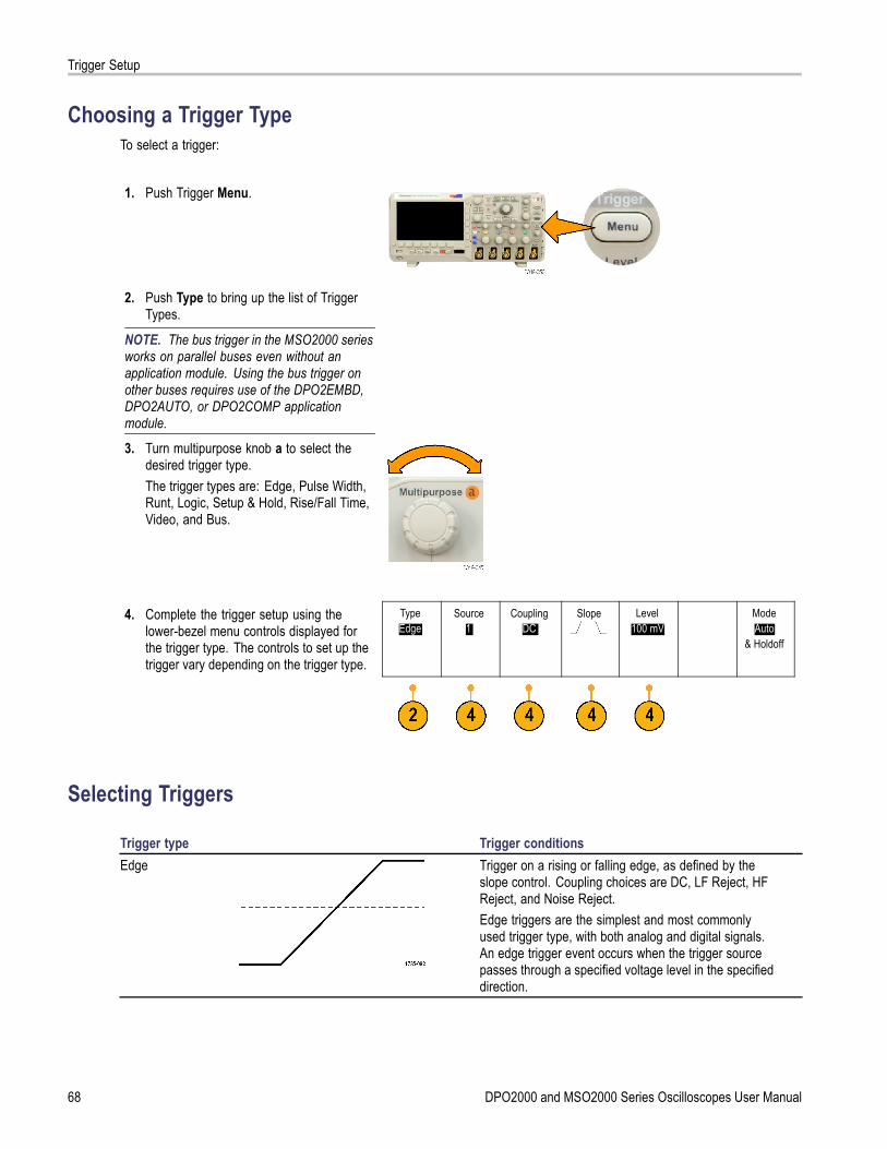
Trigger Setup
Choosing a Trigger TypeTo select a trigger:
1. Push Trigger Menu.
2. Push Type to bring up the list of TriggerTypes.
NOTE. The bus trigger in the MSO2000 seriesworks on parallel buses even without anapplication module. Using the bus trigger onother buses requires use of the DPO2EMBD,DPO2AUTO, or DPO2COMP applicationmodule.
3. Turn multipurpose knob a to select thedesired trigger type.The trigger types are: Edge, Pulse Width,Runt, Logic, Setup & Hold, Rise/Fall Time,Video, and Bus.
4. Complete the trigger setup using thelower-bezel menu controls displayed forthe trigger type. The controls to set up thetrigger vary depending on the trigger type.
TypeEdge
Source1
CouplingDC
Slope Level100 mV
ModeAuto
& Holdoff
Selecting Triggers
Trigger type Trigger conditionsEdge Trigger on a rising or falling edge, as defined by the
slope control. Coupling choices are DC, LF Reject, HFReject, and Noise Reject.Edge triggers are the simplest and most commonlyused trigger type, with both analog and digital signals.An edge trigger event occurs when the trigger sourcepasses through a specified voltage level in the specifieddirection.
68 DPO2000 and MSO2000 Series Oscilloscopes User Manual

Trigger Setup
Trigger type Trigger conditionsPulse Width Trigger on pulses that are less than, greater than, equal
to, or not equal to a specified time. You can trigger onpositive or negative pulses. Pulse width triggers areprimarily used on digital signals.
Runt Trigger on a pulse amplitude that crosses one thresholdbut fails to cross a second threshold before recrossingthe first. You can detect positive or negative (or either)runts, or only those wider than, less than, greater than,equal to, or not equal to a specified width. Runt triggersare primarily used on digital signals.
Logic Trigger when all channels transition to the specifiedstate. Use multipurpose knob a to select a channel.Push the appropriate side-bezel button to set thatchannel’s state to High (H), Low (L), or Don’t Care (X).Use the Clock side-bezel button to enable clocked(state) triggering. You can have at most a single clockchannel. Push the Clock Edge bottom bezel button tochange the polarity of the clock edge. Turn off clockedtriggering and return to unclocked (pattern) triggering byselecting the clock channel and setting it to high, low,or don’t care.For unclocked triggering, by default, triggering occurswhen the selected condition goes true. You can alsoselect triggering when the condition goes false, ortime-qualified triggering.You can use up to 20 channels for a logic trigger(4 analog and 16 digital) with MSO2000 seriesoscilloscopes.
Setup and Hold Trigger when a logic data input changes state inside ofthe setup or hold time relative to a clock edge.Setup is the amount of time that data should be stableand not change before a clock edge occurs. Hold is thetime that data should be stable and not change aftera clock edge occurs.MSO2000 series oscilloscopes are capable of multiplechannel Setup and Hold triggering, and can monitorthe state of an entire bus for setup and hold violations.You can use up to 20 channels for a Setup and Holdtrigger (4 analog and 16 digital) with MSO2000 seriesoscilloscopes.Use the Clock side-bezel button to select the clockchannel. Use the Select control, Data, and Not usedbuttons to select one or more channels you want tomonitor for setup and hold violations.
DPO2000 and MSO2000 Series Oscilloscopes User Manual 69
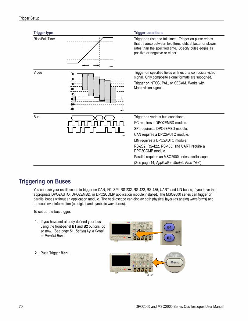
Trigger Setup
Trigger type Trigger conditionsRise/Fall Time Trigger on rise and fall times. Trigger on pulse edges
that traverse between two thresholds at faster or slowerrates than the specified time. Specify pulse edges aspositive or negative or either.
Video Trigger on specified fields or lines of a composite videosignal. Only composite signal formats are supported.Trigger on NTSC, PAL, or SECAM. Works withMacrovision signals.
Bus Trigger on various bus conditions.I2C requires a DPO2EMBD module.SPI requires a DPO2EMBD module.CAN requires a DPO2AUTO module.LIN requires a DPO2AUTO module.RS-232, RS-422, RS-485, and UART require aDPO2COMP module.Parallel requires an MSO2000 series oscilloscope.(See page 14, Application Module Free Trial.)
Triggering on BusesYou can use your oscilloscope to trigger on CAN, I2C, SPI, RS-232, RS-422, RS-485, UART, and LIN buses, if you have theappropriate DPO2AUTO, DPO2EMBD, or DPO2COMP application module installed. The MSO2000 series can trigger onparallel buses without an application module. The oscilloscope can display both physical layer (as analog waveforms) andprotocol level information (as digital and symbolic waveforms).
To set up the bus trigger:
1. If you have not already defined your bususing the front-panel B1 and B2 buttons, doso now. (See page 51, Setting Up a Serialor Parallel Bus.)
2. Push Trigger Menu.
70 DPO2000 and MSO2000 Series Oscilloscopes User Manual

Trigger Setup
3. Push Type. TypeBus
SourceBus
B1 (I2C)
Trigger OnAddress
Address07F
DirectionWrite
ModeAuto
& Holdoff
4. Turn multipurpose knob a to scroll throughthe list of trigger types until you select Bus.
B1 (I2C)5. Push Source Bus and turn multipurposeknob a to scroll through the source bus sidemenu until you select the bus that you wantto trigger on.
B2(Parallel)
6. Push Trigger On and turn multipurposeknob a to scroll through the side-bezelmenu until you select the desired trigger onfeature.If you are using the parallel bus trigger, youcan trigger on a binary or hex data value.Push the lower-bezel Data button and enterthe parameters of interest with multipurposeknobs a and b.If you are using the I2C bus trigger, youcan trigger on Start, Repeated Start,Stop, Missing Ack, Address, Data, orAddress/Data.If you are using the SPI bus trigger, you cantrigger on SS Active, MOSI, MISO, or MOSI& MISO.If you are using the CAN bus trigger, you cantrigger on Start of Frame, Type of Frame,Identifier, Data, Id & Data, End of Frame,Missing Ack, or Bit Stuffing Error.If you are using the RS-232 bus trigger, youcan trigger on Tx Start Bit, Rx Start Bit, TxEnd of Packet, Rx End of Packet,Tx Data,Rx Data, Tx Parity Error, or Rx ParityError.If you are using the LIN bus trigger, youcan trigger on Sync, Identifier, Data, Id& Data,Wakeup Frame, Sleep Frame, orError.
DPO2000 and MSO2000 Series Oscilloscopes User Manual 71
Trigger Setup
7. If you are setting up an I2C trigger and havemade a Trigger On selection of Addressor Address/Data, push the lower-bezelAddress button to access the I2C Addressside-bezel menu.Push the side-bezel Addressing Modebutton and select 7 bit or 10 bit. Pushthe side-bezel Address button. Enterthe address parameters of interest withmultipurpose knobs a and b.Then push the lower-bezel menu Directionbutton and select the direction of interest:Read, Write, or Read or Write.
If you have made a Trigger On selectionof Data or Address/Data, push thelower-bezel Data button to access the I2CData side-bezel menu.Push the Number of Bytes button andenter the number of bytes with multipurposeknob a.Push the side-bezel Addressing Modebutton and select 7 bit or 10 bit. Pushthe side-bezel Data button. Enter the dataparameters of interest with multipurposeknobs a and b.For more information on the I2C addressformats, refer to item 2 under Setting UpBus Parameters.
8. If you are setting up an SPI trigger and havemade a Trigger On selection of MOSI orMISO, push the lower-bezel Data button,push the side-bezel MOSI (or MISO) button,and enter the data parameters of interestwith multipurpose knobs a and b.Then push the Number of Bytes button andenter the number of bytes with multipurposeknob a.If you select MOSI & MISO, push thelower-bezel Data button and enter theparameters of interest in the side-bezelmenus.
72 DPO2000 and MSO2000 Series Oscilloscopes User Manual

Trigger Setup
9. If you are setting up a CAN trigger and havemade a Trigger On selection of Type ofFrame, push the lower-bezel Frame Typebutton, and select Data Frame, RemoteFrame, Error Frame, or Overload Frame.If you have made a Trigger On selection ofIdentifier, push the lower-bezel Identifierbutton, and select a Format. Then push theIdentifier side-bezel button, and enter abinary or hex value with multipurpose knobsa and b.Push the lower-bezel menu Direction buttonand select the direction of interest: Read,Write, or Read or Write.If you have made a Trigger On selectionof Data. Push the lower-bezel Data buttonand enter the parameters of interest withmultipurpose knobs a and b.
10. If you are setting up an RS-232 trigger andhave made a Trigger On selection of TxData or Rx Data, push the lower-bezel Databutton.Push the Number of Bytes button andenter the number of bytes with multipurposeknob a.Push the side-bezel Data button, and enterthe parameters of interest with multipurposeknobs a and b.
11. If you are setting up an LIN trigger andhave made a Trigger On selection ofIdentifier, Data, or Identifier & Data, pushthe lower-bezel Identifier or Data buttonsand enter the parameters of interest on theresulting side-bezel menu.If you have made a Trigger On selectionof Error, push the lower-bezel Error Typebutton and enter the parameters of intereston the resulting side-bezel menu.
I2C, SPI, CAN, and LIN Bus Trigger Data MatchingRolling window byte matching for I2C, and SPI. To use a rolling window to trigger on data, you define the numberof bytes to match. Then the oscilloscope uses a rolling window to find any match within a packet, with the window rollingone byte at a time.
For example, if the number of bytes is one, the oscilloscope will attempt to match the first byte, second byte, third, and soon within the packet.
If the number of bytes is two, the oscilloscope will try to match any two consecutive bytes, such as one and two, two andthree, three and four, and so on. If the oscilloscope finds a match, it will trigger.
DPO2000 and MSO2000 Series Oscilloscopes User Manual 73
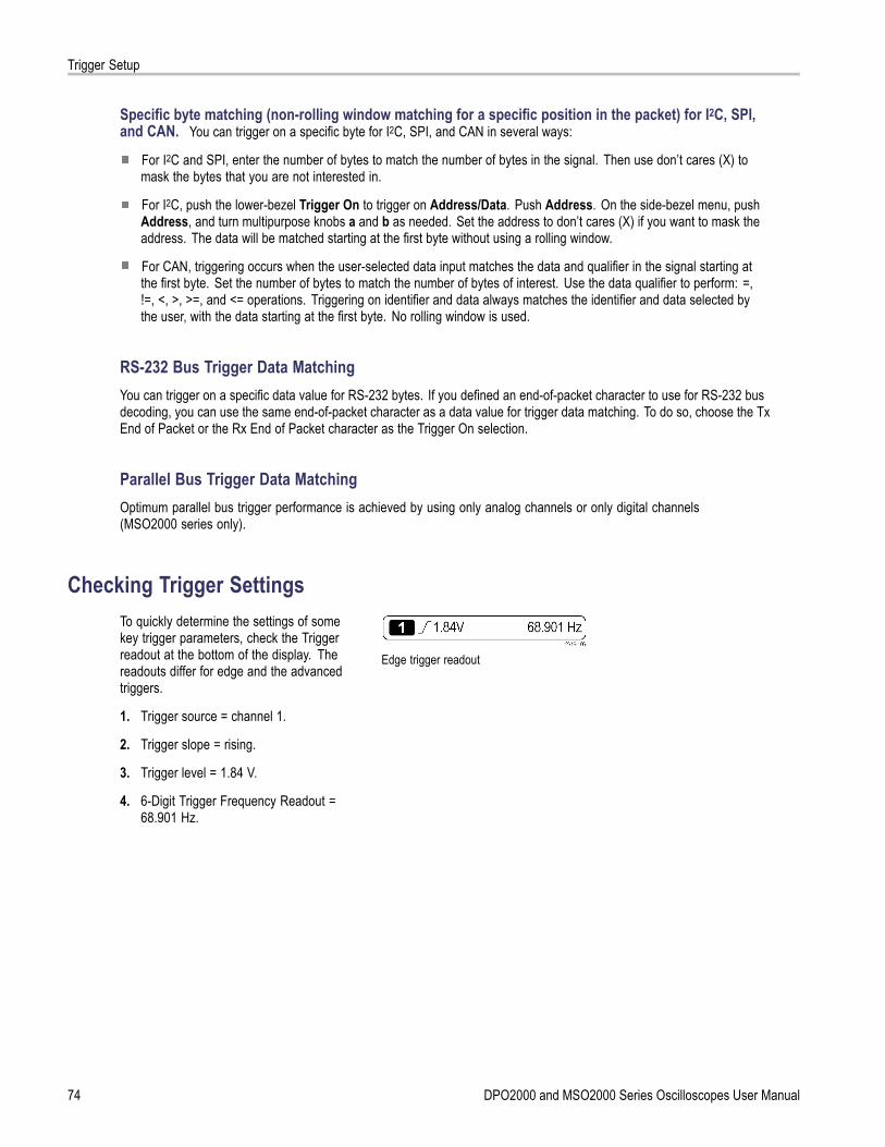
Trigger Setup
Specific byte matching (non-rolling window matching for a specific position in the packet) for I2C, SPI,and CAN. You can trigger on a specific byte for I2C, SPI, and CAN in several ways:
For I2C and SPI, enter the number of bytes to match the number of bytes in the signal. Then use don’t cares (X) tomask the bytes that you are not interested in.
For I2C, push the lower-bezel Trigger On to trigger on Address/Data. Push Address. On the side-bezel menu, pushAddress, and turn multipurpose knobs a and b as needed. Set the address to don’t cares (X) if you want to mask theaddress. The data will be matched starting at the first byte without using a rolling window.
For CAN, triggering occurs when the user-selected data input matches the data and qualifier in the signal starting atthe first byte. Set the number of bytes to match the number of bytes of interest. Use the data qualifier to perform: =,!=, <, >, >=, and <= operations. Triggering on identifier and data always matches the identifier and data selected bythe user, with the data starting at the first byte. No rolling window is used.
RS-232 Bus Trigger Data MatchingYou can trigger on a specific data value for RS-232 bytes. If you defined an end-of-packet character to use for RS-232 busdecoding, you can use the same end-of-packet character as a data value for trigger data matching. To do so, choose the TxEnd of Packet or the Rx End of Packet character as the Trigger On selection.
Parallel Bus Trigger Data MatchingOptimum parallel bus trigger performance is achieved by using only analog channels or only digital channels(MSO2000 series only).
Checking Trigger SettingsTo quickly determine the settings of somekey trigger parameters, check the Triggerreadout at the bottom of the display. Thereadouts differ for edge and the advancedtriggers.
1. Trigger source = channel 1.
2. Trigger slope = rising.
3. Trigger level = 1.84 V.
4. 6-Digit Trigger Frequency Readout =68.901 Hz.
Edge trigger readout
74 DPO2000 and MSO2000 Series Oscilloscopes User Manual

Trigger Setup
Starting and Stopping an AcquisitionAfter you have defined the acquisition and trigger parameters, start the acquisition with Run/Stop or Single.
Push Run/Stop to start acquisitions.The oscilloscope acquires repeatedlyuntil you push the button again to stopthe acquisition.
Push Single to take a single acquisition.Single sets the trigger mode to Normalfor the single acquisition.
DPO2000 and MSO2000 Series Oscilloscopes User Manual 75

Display Waveform Data
Display Waveform DataThis section contains concepts and procedures for displaying the acquired waveform.
Adding and Removing a Waveform1. To add or remove a waveform from
the display, push the correspondingfront-panel channel button or the D15-D0button.You can use the channel as a triggersource whether or not it is displayed.
Setting the Display Style and Persistence1. To set the display style, push Acquire.
2. Push Waveform Display. AverageOff
RecordLength100k
Delay
On| Off
Set Horiz.Position to
0s
WaveformDisplay
XY DisplayOff
AcquisitionDetails
76 DPO2000 and MSO2000 Series Oscilloscopes User Manual
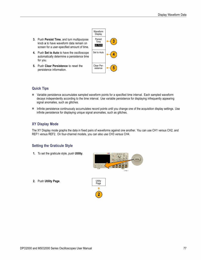
Display Waveform Data
WaveformDisplay
3. Push Persist Time, and turn multipurposeknob a to have waveform data remain onscreen for a user-specified amount of time.
PersistTime
(a) Auto
4. Push Set to Auto to have the oscilloscopeautomatically determine a persistence timefor you.
Set to Auto
5. Push Clear Persistence to reset thepersistence information.
Clear Per-sistence
Quick TipsVariable persistence accumulates sampled waveform points for a specified time interval. Each sampled waveformdecays independently according to the time interval. Use variable persistence for displaying infrequently appearingsignal anomalies, such as glitches.
Infinite persistence continuously accumulates record points until you change one of the acquisition display settings. Useinfinite persistence for displaying unique signal anomalies, such as glitches.
XY Display ModeThe XY Display mode graphs the data in fixed pairs of waveforms against one another. You can use CH1 versus CH2, andREF1 versus REF2. On four-channel models, you can also use CH3 versus CH4.
Setting the Graticule Style
1. To set the graticule style, push Utility.
2. Push Utility Page. UtilityPage
DPO2000 and MSO2000 Series Oscilloscopes User Manual 77

Display Waveform Data
3. Turn multipurpose knob a and selectDisplay.
UtilityPage
Display
BacklightIntensity
High
GraticuleFull
ScreenAnnotation
4. Push Graticule from the lower-bezel menu.
5. Select the desired style from the resultingside-bezel menu.Use the Full graticule for quick estimates ofwaveform parameters.Use the Grid graticule for full-screenmeasurements with cursors and automaticreadouts when cross hairs are not needed.Use the Cross Hair graticule for makingquick estimates of waveforms while leavingmore room for automatic readouts and otherdata.Use the Frame graticule with automaticreadouts and other screen text when displayfeatures are not needed.
Quick TipsYou can display IRE and mV graticules. To do this, set the trigger type to video and set the vertical scale to143 mV/division. (The 143 mV/division selection is available in the coarse vertical scale settings for the channel whenyou set the trigger type to video.) The oscilloscope will automatically display the IRE graticule for NTSC signals, and themV graticule for other video signals (PAL, SECAM, and custom).
Setting the LCD Backlight
1. Push Utility.
2. Push Utility Page. UtilityPage
78 DPO2000 and MSO2000 Series Oscilloscopes User Manual
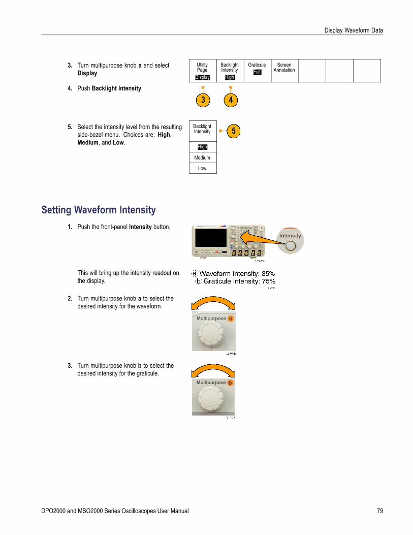
Display Waveform Data
3. Turn multipurpose knob a and selectDisplay.
UtilityPage
Display
BacklightIntensity
High
GraticuleFull
ScreenAnnotation
4. Push Backlight Intensity.
BacklightIntensity
High
Medium
5. Select the intensity level from the resultingside-bezel menu. Choices are: High,Medium, and Low.
Low
Setting Waveform Intensity1. Push the front-panel Intensity button.
This will bring up the intensity readout onthe display.
2. Turn multipurpose knob a to select thedesired intensity for the waveform.
3. Turn multipurpose knob b to select thedesired intensity for the graticule.
DPO2000 and MSO2000 Series Oscilloscopes User Manual 79
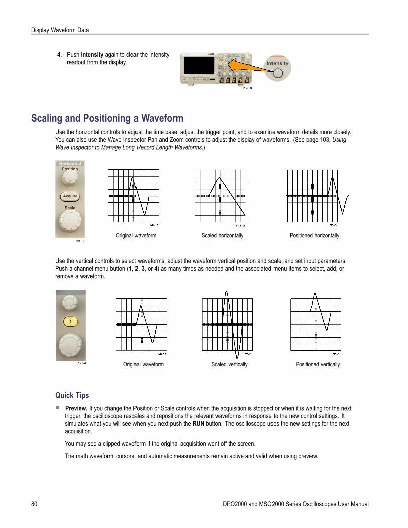
Display Waveform Data
4. Push Intensity again to clear the intensityreadout from the display.
Scaling and Positioning a WaveformUse the horizontal controls to adjust the time base, adjust the trigger point, and to examine waveform details more closely.You can also use the Wave Inspector Pan and Zoom controls to adjust the display of waveforms. (See page 103, UsingWave Inspector to Manage Long Record Length Waveforms.)
Original waveform Scaled horizontally Positioned horizontally
Use the vertical controls to select waveforms, adjust the waveform vertical position and scale, and set input parameters.Push a channel menu button (1, 2, 3, or 4) as many times as needed and the associated menu items to select, add, orremove a waveform.
Original waveform Scaled vertically Positioned vertically
Quick TipsPreview. If you change the Position or Scale controls when the acquisition is stopped or when it is waiting for the nexttrigger, the oscilloscope rescales and repositions the relevant waveforms in response to the new control settings. Itsimulates what you will see when you next push the RUN button. The oscilloscope uses the new settings for the nextacquisition.
You may see a clipped waveform if the original acquisition went off the screen.
The math waveform, cursors, and automatic measurements remain active and valid when using preview.
80 DPO2000 and MSO2000 Series Oscilloscopes User Manual

Display Waveform Data
Setting Input ParametersUse the vertical controls to select waveforms, adjust the waveform vertical position and scale, and set input parameters.
1. Push a channel menu button 1, 2, 3, or 4 tobring up the vertical menu for the designatedwaveform. The vertical menu only affectsthe selected waveform.
Pushing a channel button will also select orcancel that waveform selection.
2. Push Coupling repeatedly to select thecoupling to use.Use DC coupling to pass both AC and DCcomponents.
Coupling
DC| AC
Invert
On |Off
BandwidthFull
(1) Label (1) ProbeSetup10X More
Use AC coupling to block the DC componentand show only the AC signal.Use Ground (GND) to display the referencepotential.
3. Push Invert to invert the signal.Select Off for normal operation and Onto invert the polarity of the signal in thepreamplifier.
4. Push Bandwidth, and select the desiredbandwidth from the resulting side-bezelmenu.The default choices are Full and 20 MHz.Additional choices may appear, dependingon the probe that you use.Select Full to set the bandwidth to the fulloscilloscope bandwidth.Select 20 MHz to set the bandwidth to20 MHz.
5. Push Label to create a label for the channel.(See page 42, Labeling Channels andBuses.)
DPO2000 and MSO2000 Series Oscilloscopes User Manual 81

Display Waveform Data
6. Push Probe Setup to define probeparameters.On the resulting side-bezel menu:
Select Voltage or Current to set theprobe type for probes that do not havethe TekProbe II or TekVPI interface.
Use multipurpose knob a to set theattenuation to match the probe.
7. Push More to access additional side-bezelmenus.
8. Select Fine Scale to enable multipurposeknob a to make fine vertical scaleadjustments.
Fine Scale
9. Select Offset to enable multipurpose knob ato make vertical offset adjustments.On the side-bezel menu, choose Set to 0 Vto set the vertical offset to 0 V.For more information on offset, see QuickTips. (See page 82, Quick Tips.)
Offset
Position
10. Select Deskew to set the time skewcorrection for the channel. Turnmultipurpose knob a to adjust the timeskew (deskew) correction for the probeattached to the selected channel. This shiftsacquisition and display of the waveform leftor right, relative to the trigger time. Usethis to compensate for differences in cablelengths or probe types.
Deskew
Quick TipsUsing Probes with the TekProbe II and TekVPI Interfaces. When you attach a probe with the TekProbe II or theTekVPI interface, the oscilloscope sets the channel sensitivity, coupling, and termination resistance automatically tomatch the probe requirements. Tek Probe II probes require use of the TPA-BNC Adapter.
The Difference Between Vertical Position and Offset. Vertical position is a display function. Adjust the verticalposition to place the waveforms where you want to see them. The waveform baseline locations track adjustmentsmade to their positions.
When you adjust vertical offset, you see a similar effect, but it is actually quite different. Vertical offset is applied beforethe oscilloscope preamplifier and can be used to increase the effective dynamic range of the inputs. For example, youcan use vertical offset to look at small variations in a large DC voltage. Set the vertical offset to match the nominal DCvoltage and the signal appears in the center of the screen.
82 DPO2000 and MSO2000 Series Oscilloscopes User Manual

Display Waveform Data
Positioning and Labeling Bus SignalsAfter you set up a serial or parallel bus, you can position and label the bus signals. (See page 51, Setting Up a Serial orParallel Bus.)
To position bus signals, follow these steps:
1. Push the appropriate front-panel bus buttonto select that bus.
2. Turn multipurpose knob a to adjust thevertical position of the selected bus.
To label a bus, follow these steps:
1. Push the appropriate front-panel bus button.
2. Push Label. (See page 42, LabelingChannels and Buses.)
Bus (B1)Parallel
DefineInputs
Thresholds (B1) LabelParallel
BusDisplay
EventTable
Positioning, Scaling, and Grouping Digital ChannelsTo display digital channels, follow these steps:
1. Push the front-panel D15–D0 button.
DPO2000 and MSO2000 Series Oscilloscopes User Manual 83

Display Waveform Data
2. Push the lower-bezel D15–D0 On/Off menuitem.
D15 – D0On/Off
Thresholds Edit Labels Height
S | M L
3. Push Select, and turn multipurpose knob ato select a channel from the list. Then pushDisplay to turn on (or turn off) the waveform.You can see groups at the end of thelist by turning multipurpose knob a fullycounterclockwise.
Select(a) D0
(b) 1.04 div
Display
On| Off
Push the appropriate side-bezel button toturn on all the channels in the D7–D0 groupor in the D15–D8 group.
Turn onD7–D0
Turn onD15–D8
To position and group digital channels, followthese steps:
1. Push the front-panel D15–D0 button.
2. Turn multipurpose knob a to select thechannel or group to move.
3. To group some or all of the channels, selectand move the channels next to each otherin the display.
84 DPO2000 and MSO2000 Series Oscilloscopes User Manual
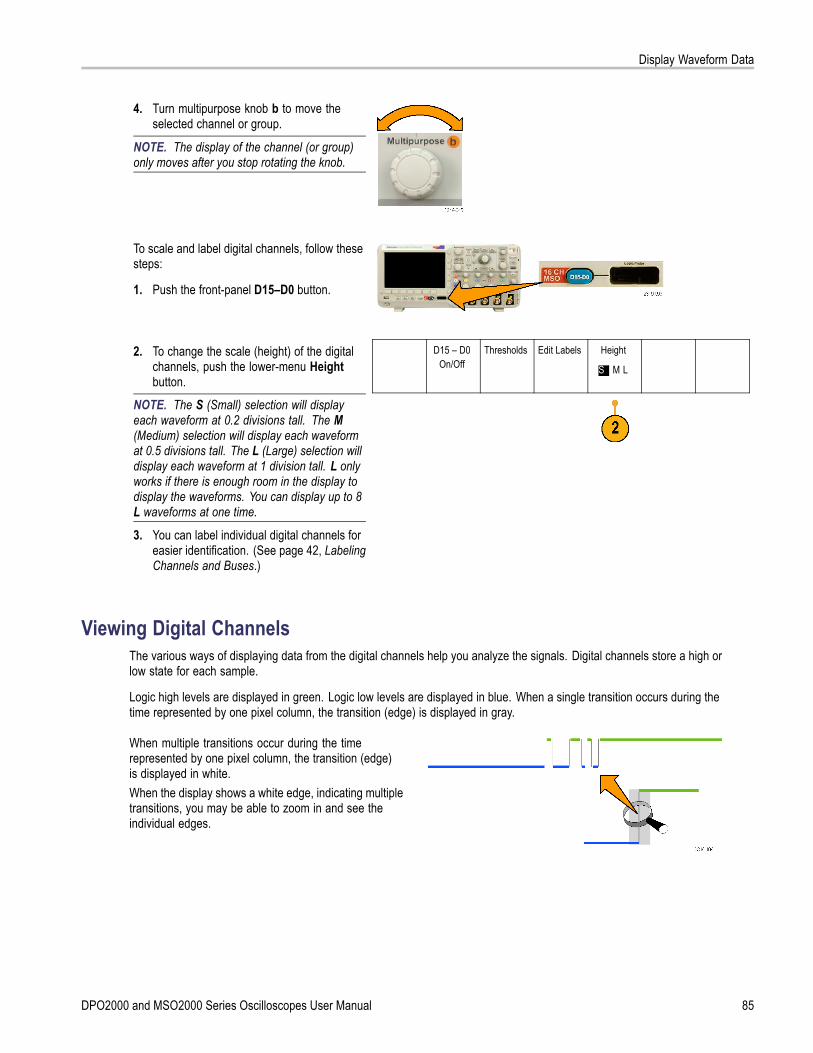
Display Waveform Data
4. Turn multipurpose knob b to move theselected channel or group.
NOTE. The display of the channel (or group)only moves after you stop rotating the knob.
To scale and label digital channels, follow thesesteps:
1. Push the front-panel D15–D0 button.
2. To change the scale (height) of the digitalchannels, push the lower-menu Heightbutton.
D15 – D0On/Off
Thresholds Edit Labels Height
S | M L
NOTE. The S (Small) selection will displayeach waveform at 0.2 divisions tall. The M(Medium) selection will display each waveformat 0.5 divisions tall. The L (Large) selection willdisplay each waveform at 1 division tall. L onlyworks if there is enough room in the display todisplay the waveforms. You can display up to 8L waveforms at one time.
3. You can label individual digital channels foreasier identification. (See page 42, LabelingChannels and Buses.)
Viewing Digital ChannelsThe various ways of displaying data from the digital channels help you analyze the signals. Digital channels store a high orlow state for each sample.
Logic high levels are displayed in green. Logic low levels are displayed in blue. When a single transition occurs during thetime represented by one pixel column, the transition (edge) is displayed in gray.
When multiple transitions occur during the timerepresented by one pixel column, the transition (edge)is displayed in white.When the display shows a white edge, indicating multipletransitions, you may be able to zoom in and see theindividual edges.
DPO2000 and MSO2000 Series Oscilloscopes User Manual 85
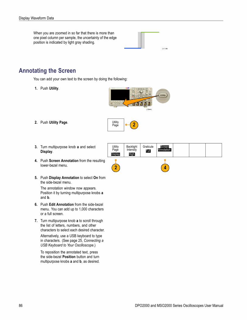
Display Waveform Data
When you are zoomed in so far that there is more thanone pixel column per sample, the uncertainty of the edgeposition is indicated by light gray shading.
Annotating the ScreenYou can add your own text to the screen by doing the following:
1. Push Utility.
2. Push Utility Page. UtilityPage
3. Turn multipurpose knob a and selectDisplay.
UtilityPage
Display
BacklightIntensity
High
GraticuleFull
ScreenAnnotation
4. Push Screen Annotation from the resultinglower-bezel menu.
5. Push Display Annotation to select On fromthe side-bezel menu.The annotation window now appears.Position it by turning multipurpose knobs aand b.
6. Push Edit Annotation from the side-bezelmenu. You can add up to 1,000 charactersor a full screen.
7. Turn multipurpose knob a to scroll throughthe list of letters, numbers, and othercharacters to select each desired character.Alternatively, use a USB keyboard to typein characters. (See page 25, Connecting aUSB Keyboard to Your Oscilloscope.)To reposition the annotated text, pressthe side-bezel Position button and turnmultipurpose knobs a and b, as desired.
86 DPO2000 and MSO2000 Series Oscilloscopes User Manual

Analyze Waveform Data
Analyze Waveform DataAfter having properly set up the acquisition, triggering, and display of your desired waveform, you can then analyze theresults. Select from features such as cursors, automatic measurements, math, and FFT.
Taking Automatic MeasurementsTo take an automatic measurement:
1. Push Measure.
2. Push Add Measurement. Add Mea-surement
RemoveMeasure-
ment
Indicators GatingScreen
High-LowMethod
Auto
BringCursors on
Screen
ConfigureCursors
3. Turn multipurpose knob a to select thespecific measurement. If needed, thenturn multipurpose knob b to select thechannel to measure on. Then push OK AddMeasurement.
4. To remove a measurement, push RemoveMeasurement. Then push the side-bezelmenu for the measurement you want toremove, or Remove All. Then push OKRemove Measurement.
Quick TipsTo remove all measurements, select Remove All Measurements.
A symbol appears instead of the expected numerical measurement if a vertical clipping condition exists. Part of thewaveform is above or below the display. To obtain a proper numerical measurement, turn the vertical scale and positionknobs to make all of the waveform appear in the display.
DPO2000 and MSO2000 Series Oscilloscopes User Manual 87

Analyze Waveform Data
Selecting Automatic MeasurementsThe following tables list each automatic measurement by category: time or amplitude. (See page 87, Taking AutomaticMeasurements.)
Time MeasurementsMeasurement DescriptionFrequency The first cycle in a waveform or gated region. Frequency is the reciprocal of the period; it
is measured in hertz (Hz) where one Hz is one cycle per second.
Period The time required to complete the first cycle in a waveform or gated region. Period isthe reciprocal of frequency and is measured in seconds.
Rise Time The time required for the leading edge of the first pulse in the waveform or gated regionto rise from the low reference value to the high reference value of the final value.
Fall Time The time required for the falling edge of the first pulse in the waveform or gated region tofall from the high reference value to the low reference value of the final value.
Delay The time between the mid reference (default 50%) amplitude point of two differentwaveforms. See also Phase.
Phase The amount of time that one waveform leads or lags another waveform, expressed indegrees where 360° makes up one waveform cycle. See also Delay.
Positive PulseWidth
The distance (time) between the mid reference (default 50%) amplitude points of apositive pulse. The measurement is made on the first pulse in the waveform or gatedregion.
Negative PulseWidth
The distance (time) between the mid reference (default 50%) amplitude points of anegative pulse. The measurement is made on the first pulse in the waveform or gatedregion.
Positive DutyCycle
The ratio of the positive pulse width to the signal period expressed as a percentage. Theduty cycle is measured on the first cycle in the waveform or gated region.
Negative DutyCycle
The ratio of the negative pulse width to the signal period expressed as a percentage.The duty cycle is measured on the first cycle in the waveform or gated region.
88 DPO2000 and MSO2000 Series Oscilloscopes User Manual
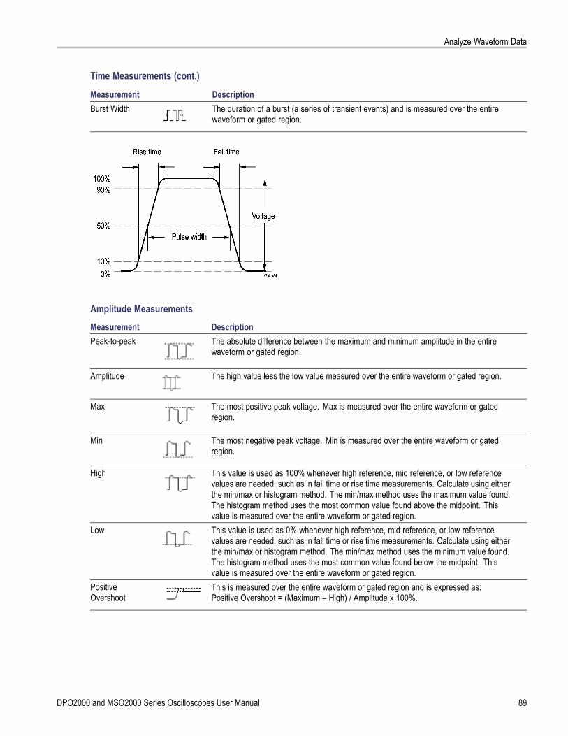
Analyze Waveform Data
Time Measurements (cont.)
Measurement DescriptionBurst Width The duration of a burst (a series of transient events) and is measured over the entire
waveform or gated region.
Amplitude MeasurementsMeasurement DescriptionPeak-to-peak The absolute difference between the maximum and minimum amplitude in the entire
waveform or gated region.
Amplitude The high value less the low value measured over the entire waveform or gated region.
Max The most positive peak voltage. Max is measured over the entire waveform or gatedregion.
Min The most negative peak voltage. Min is measured over the entire waveform or gatedregion.
High This value is used as 100% whenever high reference, mid reference, or low referencevalues are needed, such as in fall time or rise time measurements. Calculate using eitherthe min/max or histogram method. The min/max method uses the maximum value found.The histogram method uses the most common value found above the midpoint. Thisvalue is measured over the entire waveform or gated region.
Low This value is used as 0% whenever high reference, mid reference, or low referencevalues are needed, such as in fall time or rise time measurements. Calculate using eitherthe min/max or histogram method. The min/max method uses the minimum value found.The histogram method uses the most common value found below the midpoint. Thisvalue is measured over the entire waveform or gated region.
PositiveOvershoot
This is measured over the entire waveform or gated region and is expressed as:Positive Overshoot = (Maximum – High) / Amplitude x 100%.
DPO2000 and MSO2000 Series Oscilloscopes User Manual 89
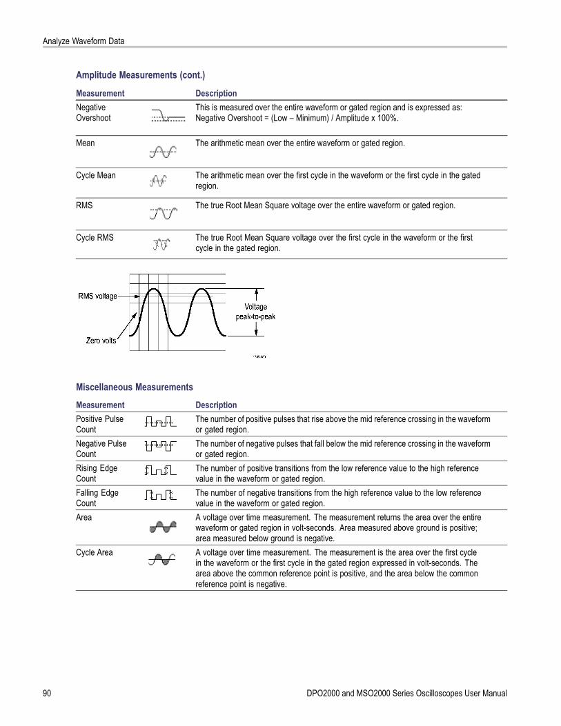
Analyze Waveform Data
Amplitude Measurements (cont.)
Measurement DescriptionNegativeOvershoot
This is measured over the entire waveform or gated region and is expressed as:Negative Overshoot = (Low – Minimum) / Amplitude x 100%.
Mean The arithmetic mean over the entire waveform or gated region.
Cycle Mean The arithmetic mean over the first cycle in the waveform or the first cycle in the gatedregion.
RMS The true Root Mean Square voltage over the entire waveform or gated region.
Cycle RMS The true Root Mean Square voltage over the first cycle in the waveform or the firstcycle in the gated region.
Miscellaneous MeasurementsMeasurement DescriptionPositive PulseCount
The number of positive pulses that rise above the mid reference crossing in the waveformor gated region.
Negative PulseCount
The number of negative pulses that fall below the mid reference crossing in the waveformor gated region.
Rising EdgeCount
The number of positive transitions from the low reference value to the high referencevalue in the waveform or gated region.
Falling EdgeCount
The number of negative transitions from the high reference value to the low referencevalue in the waveform or gated region.
Area A voltage over time measurement. The measurement returns the area over the entirewaveform or gated region in volt-seconds. Area measured above ground is positive;area measured below ground is negative.
Cycle Area A voltage over time measurement. The measurement is the area over the first cyclein the waveform or the first cycle in the gated region expressed in volt-seconds. Thearea above the common reference point is positive, and the area below the commonreference point is negative.
90 DPO2000 and MSO2000 Series Oscilloscopes User Manual
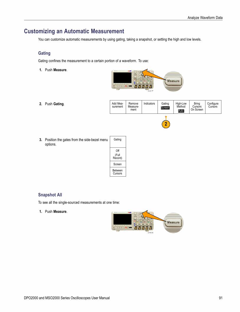
Analyze Waveform Data
Customizing an Automatic MeasurementYou can customize automatic measurements by using gating, taking a snapshot, or setting the high and low levels.
GatingGating confines the measurement to a certain portion of a waveform. To use:
1. Push Measure.
2. Push Gating. Add Mea-surement
RemoveMeasure-
ment
Indicators GatingScreen
High-LowMethod
Auto
BringCursors
On Screen
ConfigureCursors
3. Position the gates from the side-bezel menuoptions.
Gating
Off(Full
Record)
Screen
BetweenCursors
Snapshot AllTo see all the single-sourced measurements at one time:
1. Push Measure.
DPO2000 and MSO2000 Series Oscilloscopes User Manual 91
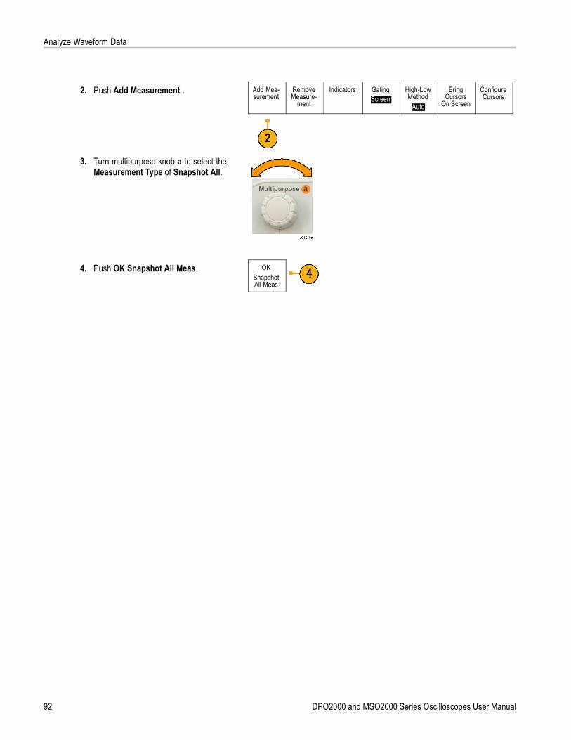
Analyze Waveform Data
2. Push Add Measurement . Add Mea-surement
RemoveMeasure-
ment
Indicators GatingScreen
High-LowMethod
Auto
BringCursors
On Screen
ConfigureCursors
3. Turn multipurpose knob a to select theMeasurement Type of Snapshot All.
4. Push OK Snapshot All Meas. OKSnapshotAll Meas
92 DPO2000 and MSO2000 Series Oscilloscopes User Manual
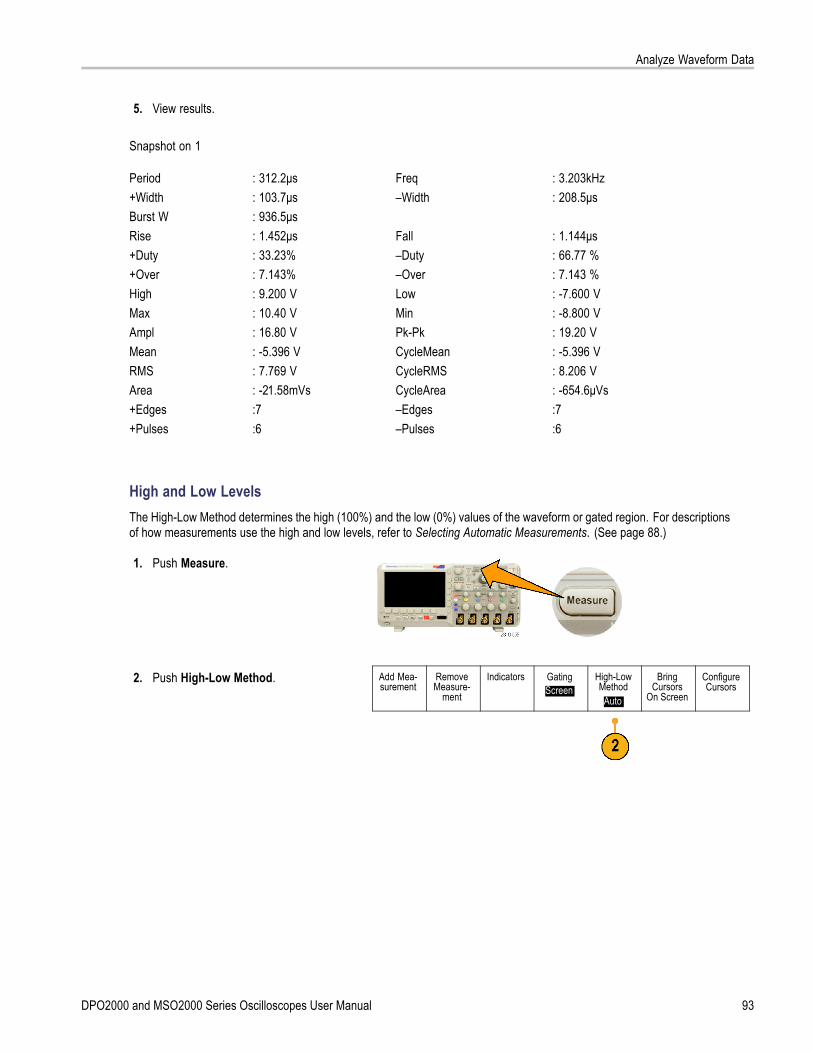
Analyze Waveform Data
5. View results.
Snapshot on 1
Period+WidthBurst WRise+Duty+OverHighMaxAmplMeanRMSArea+Edges+Pulses
: 312.2μs: 103.7μs: 936.5μs: 1.452μs: 33.23%: 7.143%: 9.200 V: 10.40 V: 16.80 V: -5.396 V: 7.769 V: -21.58mVs:7:6
Freq–Width
Fall–Duty–OverLowMinPk-PkCycleMeanCycleRMSCycleArea–Edges–Pulses
: 3.203kHz: 208.5μs
: 1.144μs: 66.77 %: 7.143 %: -7.600 V: -8.800 V: 19.20 V: -5.396 V: 8.206 V: -654.6μVs:7:6
High and Low LevelsThe High-Low Method determines the high (100%) and the low (0%) values of the waveform or gated region. For descriptionsof how measurements use the high and low levels, refer to Selecting Automatic Measurements. (See page 88.)
1. Push Measure.
2. Push High-Low Method. Add Mea-surement
RemoveMeasure-
ment
Indicators GatingScreen
High-LowMethod
Auto
BringCursors
On Screen
ConfigureCursors
DPO2000 and MSO2000 Series Oscilloscopes User Manual 93

Analyze Waveform Data
3. Set the levels from the side-bezel menu. AutoSelect
Use the Histogram method for pulses. Histogram(best forpulses)
Use the Min-Max method for all otherwaveforms.
Min-Max(all other
wave-forms)
For descriptions of the high and lowmeasurements, refer to the table of AmplitudeMeasurements under Selecting AutomaticMeasurements. (See page 89.)
Taking Manual Measurements with CursorsCursors are on-screen markers that you position in the waveform display to take manual measurements on acquired data.They appear as horizontal and/or as vertical lines. To use cursors on analog or digital channels:
1. Push Cursors.This changes the cursor state. The threestates are:
No cursors appear on the screen.
Two vertical waveform cursorsappear. They are attached to theselected analog waveform or digitalwaveforms.
Four screen cursors appear. Two arevertical and two are horizontal. Theyare no longer specifically attached toa waveform.
2. Push Cursors again.In the example, two vertical cursorsappear on the selected screen waveform.As you turn multipurpose knob a, youmove one cursor to the right or left. Asyou turn knob b, you move the othercursor.If you change the selected waveform bypushing the front-panel 1, 2, 3, 4, M, R,or D15-D0 button, both cursors jump tothe new selected waveform.
94 DPO2000 and MSO2000 Series Oscilloscopes User Manual
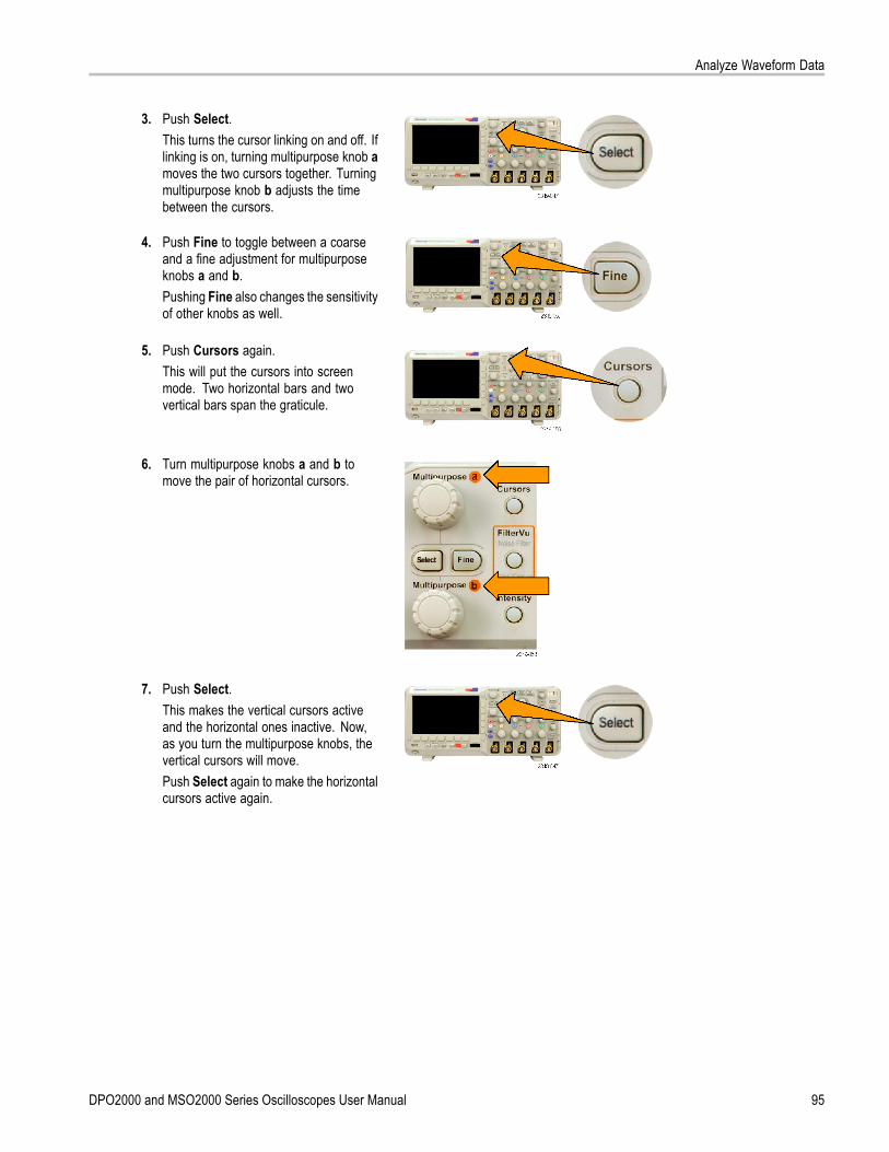
Analyze Waveform Data
3. Push Select.This turns the cursor linking on and off. Iflinking is on, turning multipurpose knob amoves the two cursors together. Turningmultipurpose knob b adjusts the timebetween the cursors.
4. Push Fine to toggle between a coarseand a fine adjustment for multipurposeknobs a and b.Pushing Fine also changes the sensitivityof other knobs as well.
5. Push Cursors again.This will put the cursors into screenmode. Two horizontal bars and twovertical bars span the graticule.
6. Turn multipurpose knobs a and b tomove the pair of horizontal cursors.
7. Push Select.This makes the vertical cursors activeand the horizontal ones inactive. Now,as you turn the multipurpose knobs, thevertical cursors will move.Push Select again to make the horizontalcursors active again.
DPO2000 and MSO2000 Series Oscilloscopes User Manual 95

Analyze Waveform Data
8. View the cursor and the cursor readout.You can take timing measurements withcursors on digital channels, but notamplitude measurements.
9. Push Cursors again. This will turn offthe cursor mode. The screen will nolonger display the cursors and the cursorreadout.
Using Cursor ReadoutsCursor readouts supply textual and numeric information relating to the current cursor positions. The oscilloscope alwaysshows the readouts when the cursors are turned on.
Readouts appear in the upper right corner of the graticule. If Zoom is on, the readout appears in the upper right corner ofthe zoom window.
When a bus is selected, the readout shows the decoded bus data in the format you have selected, hexadecimal, binary, orASCII (RS-232 only). When a digital channel is selected, the cursors show the values of all displayed digital channels.
NOTE. When buses are selected, the data value at that point is displayed in the cursor readout.
Δ Readout:The Δ readouts indicate the differencebetween the cursor positions.
a Readout:Indicates that the value is controlled bymultipurpose knob a.
b Readout:Indicates that the value is controlled bymultipurpose knob b.
96 DPO2000 and MSO2000 Series Oscilloscopes User Manual

Analyze Waveform Data
The horizontal cursor lines on the displaymeasure the vertical parameters, typicallyvoltage.
The vertical cursor lines on the displaymeasure horizontal parameters, typicallytime.
The square and circle shapes in the readout map to the multipurpose knobs when both vertical and horizontal cursorsare present.
Using XY CursorsWhen the XY Display mode is on, the cursor readouts will appear to the right of the lower graticule (XY). You can choosewhich readouts to display: rectangular, polar, product, or ratio.
NOTE. Push the Measure button for additional cursor menu options, such as Bring Cursors On Screen and ConfigureCursors.
Using Math WaveformsCreate math waveforms to support the analysis of your channel and reference waveforms. By combining and transformingsource waveforms and other data into math waveforms, you can derive the data view that your application requires.
NOTE. Math waveforms are not available for use with serial buses.
Use the following procedure for executing simple (+, –, ×) math operations on two waveforms:
1. Push M for the Math menu.
2. Push Dual Wfm Math. Dual WfmMath
FFT (M) Label
3. On the side-bezel menu, set the sources tochannel 1, 2, 3, 4, or to reference waveformsR1 or R2. Choose the +, –, or x operators.
DPO2000 and MSO2000 Series Oscilloscopes User Manual 97
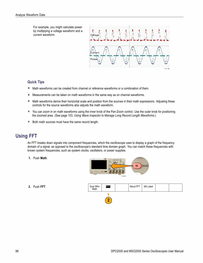
Analyze Waveform Data
For example, you might calculate powerby multiplying a voltage waveform and acurrent waveform.
Quick TipsMath waveforms can be created from channel or reference waveforms or a combination of them.
Measurements can be taken on math waveforms in the same way as on channel waveforms.
Math waveforms derive their horizontal scale and position from the sources in their math expressions. Adjusting thesecontrols for the source waveforms also adjusts the math waveform.
You can zoom in on math waveforms using the inner knob of the Pan-Zoom control. Use the outer knob for positioningthe zoomed area. (See page 103, Using Wave Inspector to Manage Long Record Length Waveforms.)
Both math sources must have the same record length.
Using FFTAn FFT breaks down signals into component frequencies, which the oscilloscope uses to display a graph of the frequencydomain of a signal, as opposed to the oscilloscope’s standard time domain graph. You can match these frequencies withknown system frequencies, such as system clocks, oscillators, or power supplies.
1. Push Math.
2. Push FFT. Dual WfmMath
FFT About FFT (M) Label
98 DPO2000 and MSO2000 Series Oscilloscopes User Manual
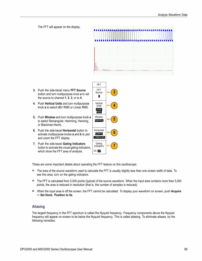
Analyze Waveform Data
The FFT will appear on the display.
FFT
3. Push the side-bezel menu FFT Sourcebutton and turn multipurpose knob a to setthe source to channel 1, 2, 3, or to 4.
FFTSource
1
4. Push Vertical Units and turn multipurposeknob a to select dBV RMS or Linear RMS.
VerticalUnits
LinearRMS
5. Push Window and turn multipurpose knob ato select Rectangular, Hamming, Hanning,or Blackman-Harris.
WindowHanning
6. Push the side-bezel Horizontal button toactivate multipurpose knobs a and b to panand zoom the FFT display.
Horizontal625kHz
1.25kHz/div
7. Push the side-bezel Gating Indicatorsbutton to activate the visual gating indicators,which show the FFT area of analysis.
GatingIndicators
On |Off
These are some important details about operating the FFT feature on this oscilloscope:
The area of the source waveform used to calculate the FFT is usually slightly less than one screen width of data. Tosee this area, turn on the gating indicators.
The FFT is calculated from 5,000 points (typical) of the source waveform. When the input area contains more than 5,000points, the area is reduced in resolution (that is, the number of samples is reduced).
When the input area is off the screen, the FFT cannot be calculated. To display your waveform on screen, push Acquire-> Set Horiz. Position to 0s.
AliasingThe largest frequency in the FFT spectrum is called the Nyquist frequency. Frequency components above the Nyquistfrequency will appear on screen to be below the Nyquist frequency. This is called aliasing. To eliminate aliases, try thefollowing remedies:
DPO2000 and MSO2000 Series Oscilloscopes User Manual 99

Analyze Waveform Data
Set up the FFT so that the Nyquist frequency is above the major frequency components of your signal. To do this, adjustthe Horizontal time/div, which affects the Nyquist frequency.
Use the FilterVu low-pass filter to remove aliases from the source waveform. To do this, set the filter frequency to itsminimum value (while zoom is off and acquisitions are running). Aliased frequencies are reduced to no more than 1% oftheir original amplitude. Using a filter frequency above the minimum can reduce, but not eliminate, aliasing.
Recognize and ignore the aliased frequencies.
NOTE. The Nyquist frequency is one-half the sample rate. When the FFT is taken from a reduced-resolution waveform, theNyquist frequency will be half of the reduced sample rate of the waveform, not half of the full sample rate of the oscilloscope.
Quick TipsIf desired, use the zoom feature along with the horizontal Position and Scale controls to magnify and position theFFT waveform.
Use the default dBV RMS scale to see a detailed view of multiple frequencies, even if they have very different amplitudes.Use the linear RMS scale to see an overall view of how all frequencies compare to each other.
The FFT feature provides four windows. Each is a trade-off between frequency resolution and magnitude accuracy.What you want to measure and your source signal characteristics help determine which window to use. Use the followingguidelines to select the best window.
Description WindowHanningThis is a very good window for measuring amplitude accuracy but less so for resolvingfrequencies.Use Hanning for measuring sine, periodic, and narrow band random noise. This windowworks on transients or bursts where the signal levels before and after the event aresignificantly different.RectangularThis is the best type of window for resolving frequencies that are very close to the samevalue but worst for accurately measuring the amplitude of those frequencies. It is the besttype for measuring the frequency spectrum of nonrepetitive signals and measuring frequencycomponents near DC.Use Rectangular for measuring transients or bursts where the signal level before and after theevent are nearly equal. Also, use this window for equal-amplitude sine waves with frequenciesthat are very close and for broadband random noise with a relatively slow varying spectrum.HammingThis is a very good window for resolving frequencies that are very close to the same valuewith somewhat improved amplitude accuracy over the rectangular window. It has a slightlybetter frequency resolution than the Hanning.Use Hamming for measuring sine, periodic, and narrow band random noise. This windowworks on transients or bursts where the signal levels before and after the event aresignificantly different.
100 DPO2000 and MSO2000 Series Oscilloscopes User Manual

Analyze Waveform Data
Description WindowBlackman-HarrisThis is the best window for measuring the amplitude of frequencies but worst at resolvingfrequencies.Use Blackman-Harris for measuring predominantly single frequency waveforms to look forhigher order harmonics.
Using Reference WaveformsCreate a reference waveform to store a waveform. For example, you might do this to set up a standard against which tocompare other waveforms. To use the reference waveforms:
1. Push Ref R. This brings up the lower-bezelreference menu.
2. Use the resulting lower-bezel menuselections to display or select a referencewaveform.
(R1) |(On)3-May-07
(R2) |(Off)
DPO2000 and MSO2000 Series Oscilloscopes User Manual 101

Analyze Waveform Data
3. Use the side-bezel menu and themultipurpose knobs to adjust the verticaland horizontal settings of the referencewaveform.
R1
Vertical0.00 div
100 mV/div
Horizontal0.00 s
4.00 μs/div
Quick TipsSelecting and Displaying Reference Waveforms. You can display all the reference waveforms at the same time. Pushthe appropriate screen button to select a particular reference waveform.
Removing Reference Waveforms from the Display. To remove a reference waveform from the display, push thefront-panel R button to access the lower-bezel menu. Then push the associated button from the lower-bezel menuto turn it off.
Scaling and Positioning a Reference Waveform. You can position and scale a reference waveform independently from allother displayed waveforms. Select the reference waveform and then adjust it with a multipurpose knob. You can dothis whether acquisition is running or not.
If a reference waveform is selected, scaling and repositioning of the reference waveform operates the same waywhether zoom is turned on or off.
102 DPO2000 and MSO2000 Series Oscilloscopes User Manual

Analyze Waveform Data
Using Wave Inspector to Manage Long Record Length WaveformsThe Wave Inspector controls (zoom/pan, play/pause, marks, search) help you to efficiently work with long record lengthwaveforms. To magnify a waveform horizontally, turn the Zoom knob (center knob). To scroll through a zoomed waveform,turn the Pan knob.
The Pan-Zoom Control consists of:
1. An outer pan knob
2. An inner zoom knob
Zooming a WaveformTo use zoom:
1. Turn the inner knob on the Pan-Zoomcontrol clockwise to zoom in on aselected portion of the waveform. Turnthe knob counterclockwise to zoom backout.
2. Alternatively, enable or disable the zoommode by pushing the zoom button.
DPO2000 and MSO2000 Series Oscilloscopes User Manual 103

Analyze Waveform Data
3. Examine the zoomed view of thewaveform that appears on the larger,lower portion of the display. The upperportion of the display will show theposition and size of the zoomed portionin the waveform, within the context of theoverall record.
Panning a WaveformWhile the zoom feature is on, you can use the pan feature to quickly scroll through the waveform. To use pan:
1. Turn the pan (outer) knob of thepan-zoom controls to pan thewaveform.Turn the knob clockwise to panforward. Turn it counterclockwise topan backwards. The further you turnthe knob, the faster the zoom windowpans.
Playing and Pausing a WaveformUse the play-pause feature to automatically pan through a waveform record. To use it:
1. Enable the play-pause mode bypushing the play-pause button.
2. Adjust the play speed by turning thepan (outer) knob further. The furtheryou turn it, the faster it goes.
104 DPO2000 and MSO2000 Series Oscilloscopes User Manual
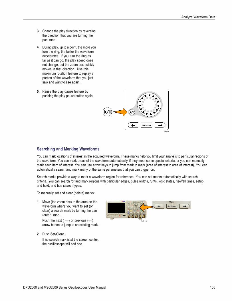
Analyze Waveform Data
3. Change the play direction by reversingthe direction that you are turning thepan knob.
4. During play, up to a point, the more youturn the ring, the faster the waveformaccelerates. If you turn the ring asfar as it can go, the play speed doesnot change, but the zoom box quicklymoves in that direction. Use thismaximum rotation feature to replay aportion of the waveform that you justsaw and want to see again.
5. Pause the play-pause feature bypushing the play-pause button again.
Searching and Marking WaveformsYou can mark locations of interest in the acquired waveform. These marks help you limit your analysis to particular regions ofthe waveform. You can mark areas of the waveform automatically, if they meet some special criteria, or you can manuallymark each item of interest. You can use arrow keys to jump from mark to mark (area of interest to area of interest). You canautomatically search and mark many of the same parameters that you can trigger on.
Search marks provide a way to mark a waveform region for reference. You can set marks automatically with searchcriteria. You can search for and mark regions with particular edges, pulse widths, runts, logic states, rise/fall times, setupand hold, and bus search types.
To manually set and clear (delete) marks:
1. Move (the zoom box) to the area on thewaveform where you want to set (orclear) a search mark by turning the pan(outer) knob.Push the next ( →) or previous (←)arrow button to jump to an existing mark.
2. Push Set/Clear.If no search mark is at the screen center,the oscilloscope will add one.
DPO2000 and MSO2000 Series Oscilloscopes User Manual 105
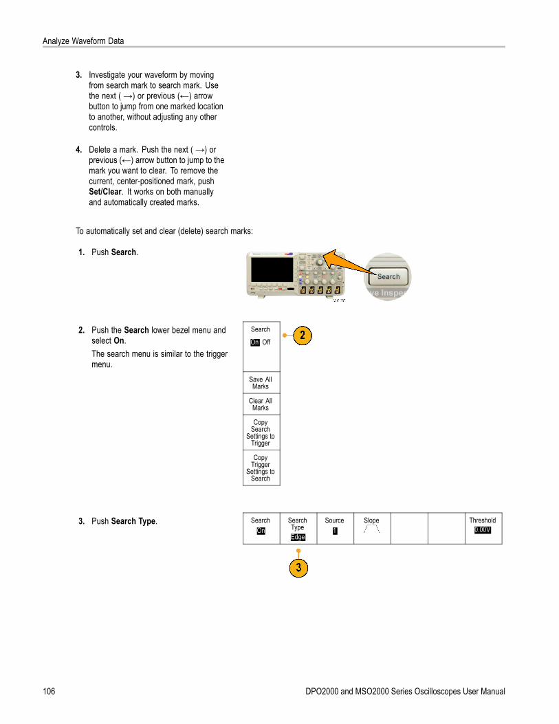
Analyze Waveform Data
3. Investigate your waveform by movingfrom search mark to search mark. Usethe next ( →) or previous (←) arrowbutton to jump from one marked locationto another, without adjusting any othercontrols.
4. Delete a mark. Push the next ( →) orprevious (←) arrow button to jump to themark you want to clear. To remove thecurrent, center-positioned mark, pushSet/Clear. It works on both manuallyand automatically created marks.
To automatically set and clear (delete) search marks:
1. Push Search.
2. Push the Search lower bezel menu andselect On.The search menu is similar to the triggermenu.
Search
On| Off
Save AllMarks
Clear AllMarks
CopySearch
Settings toTrigger
CopyTrigger
Settings toSearch
3. Push Search Type. SearchOn
SearchTypeEdge
Source1
Slope Threshold0.00V
106 DPO2000 and MSO2000 Series Oscilloscopes User Manual
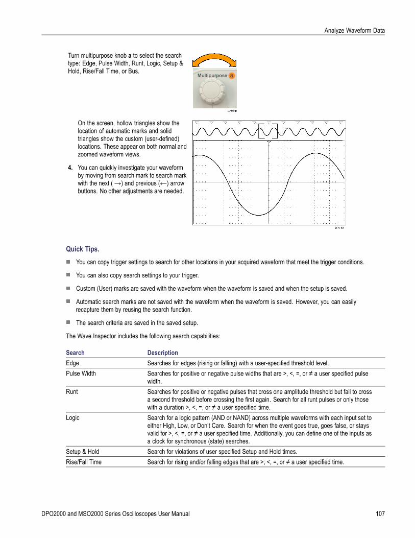
Analyze Waveform Data
Turn multipurpose knob a to select the searchtype: Edge, Pulse Width, Runt, Logic, Setup &Hold, Rise/Fall Time, or Bus.
On the screen, hollow triangles show thelocation of automatic marks and solidtriangles show the custom (user-defined)locations. These appear on both normal andzoomed waveform views.
4. You can quickly investigate your waveformby moving from search mark to search markwith the next ( →) and previous (←) arrowbuttons. No other adjustments are needed.
Quick Tips.You can copy trigger settings to search for other locations in your acquired waveform that meet the trigger conditions.
You can also copy search settings to your trigger.
Custom (User) marks are saved with the waveform when the waveform is saved and when the setup is saved.
Automatic search marks are not saved with the waveform when the waveform is saved. However, you can easilyrecapture them by reusing the search function.
The search criteria are saved in the saved setup.
The Wave Inspector includes the following search capabilities:
Search DescriptionEdge Searches for edges (rising or falling) with a user-specified threshold level.Pulse Width Searches for positive or negative pulse widths that are >, <, =, or ≠ a user specified pulse
width.Runt Searches for positive or negative pulses that cross one amplitude threshold but fail to cross
a second threshold before crossing the first again. Search for all runt pulses or only thosewith a duration >, <, =, or ≠ a user specified time.
Logic Search for a logic pattern (AND or NAND) across multiple waveforms with each input set toeither High, Low, or Don’t Care. Search for when the event goes true, goes false, or staysvalid for >, <, =, or ≠ a user specified time. Additionally, you can define one of the inputs asa clock for synchronous (state) searches.
Setup & Hold Search for violations of user specified Setup and Hold times.Rise/Fall Time Search for rising and/or falling edges that are >, <, =, or ≠ a user specified time.
DPO2000 and MSO2000 Series Oscilloscopes User Manual 107

Analyze Waveform Data
Search DescriptionBus Parallel: Search for a binary or hex value (MSO2000 series only).
I2C: Search for Start, Repeated Start, Stop, Missing Ack, Address, Data, or Address andData.SPI: Search for SS Active, MOSI, MISO, or MOSI & MISOCAN: Search for Start of Frame, Type of Frame (Data, Remote, Error, Overload), Identifier(standard or extended), Data, Identifier and Data, End of Frame, Missing Ack, or Bit StuffingErrorRS-232, RS-422, RS-485, UART: Search for Tx Start Bit, Rx Start Bit, Tx End of Packet, RxEnd of Packet, Tx Data, Rx Data, Tx Parity Error, or Rx Parity Error.LIN: Search for Synch, Identifier, Data, ID & Data, Wakeup Frame, Sleep Frame, or Error
108 DPO2000 and MSO2000 Series Oscilloscopes User Manual
Save and Recall Information
Save and Recall InformationThe oscilloscope provides permanent storage for setups, waveforms, and screen images. Use the internal storage of theoscilloscope to save setup files and reference waveform data.
Use external storage, such as USB flash drives, to save setups, waveforms, and screen images. Use the external storage tocarry data to remote computers for further analysis and for archiving.
External File Structure. If you are saving information to external storage, select the appropriate menu (such as theTo File side-bezel menu to save setups and waveforms) and turn multipurpose knob a to scroll through the external filestructure. Drive E is the USB flash drive plugged into the USB Host port on the front of the oscilloscope.
Use multipurpose knob a to scroll through the list of files. Use the Select front panel button to open and close folders.
Naming Your File. The oscilloscope gives the files it creates a default name in the following format:
tekXXXXX.set for individual setup files where XXXXX is an integer from 00000 to 99999; the name is shortened totXXXXX.set for setup files saved with the Save All function
tekXXXXX.png, tekXXXXX.bmp, or tekXXXXX.tif for individual image files; the name is shortened to tXXXXX.png,tXXXXX.bmp, or tXXXXX.tif for image files saved with the Save All function
tXXXXYYY.csv for all spreadsheet files or tXXXXYYY.isf for all internal format files
For waveform and for internal format files, the XXXX is an integer from 0000 to 9999. The YYY is the channel of thewaveform, and can be one of the following:
CH1, CH2, CH3, or CH4 for the analog channels
D00, D01, D02, D03, and so on through D15 for the digital channels
MTH for a math waveform
RF1 or RF2 for reference memory waveforms
ALL for a single spreadsheet file containing multiple channels when you select Save All Waveforms
NOTE. Only analog channels and waveforms derived from analog channels (such as math and reference) can be saved toan ISF file. When saving all channels in ISF format, a group of files will be saved. Each will have the same value for XXXXX,but the YYY values will be set to the different channels that were turned on when the Save All Waveforms was performed.
For example, the first time you save a file, that file is named tek00000 for a setup or image file, and t0000 for a waveform orinternal format file. The next time you save the same type of file, the file will be named tek00001 or t0001 respectively.
For bus event tables, the XXXX is an integer from 0000 to 9999. The YYY is the type of bus, and can be one of the following:
RS2 (designates RS-232, RS-422, RS-485 or UART buses), I2C, SPI, CAN, or LIN for a serial bus
PAR for a parallel bus
DPO2000 and MSO2000 Series Oscilloscopes User Manual 109
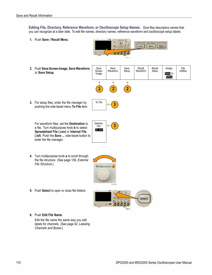
Save and Recall Information
Editing File, Directory, Reference Waveform, or Oscilloscope Setup Names. Give files descriptive names thatyou can recognize at a later date. To edit file names, directory names, reference waveform and oscilloscope setup labels:
1. Push Save / Recall Menu.
2. Push Save Screen Image, Save Waveform,or Save Setup.
SaveScreenImage
SaveWaveform
SaveSetup
RecallWaveform
RecallSetup
Assign
Save| toSetup
FileUtilities
3. For setup files, enter the file manager bypushing the side-bezel menu To File item.
To File
For waveform files, set the Destination toa file. Turn multipurpose knob b to selectSpreadsheet File (.csv) or Internal File(.isf). Push the Save ... side-bezel button toenter the file manager.
Destina-tion
(b) .csv
4. Turn multipurpose knob a to scroll throughthe file structure. (See page 109, ExternalFile Structure.)
5. Push Select to open or close file folders.
6. Push Edit File Name.Edit the file name the same way you editlabels for channels. (See page 42, LabelingChannels and Buses.)
110 DPO2000 and MSO2000 Series Oscilloscopes User Manual
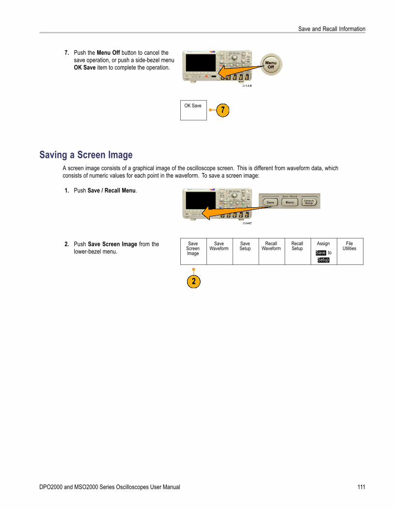
Save and Recall Information
7. Push the Menu Off button to cancel thesave operation, or push a side-bezel menuOK Save item to complete the operation.
OK Save
Saving a Screen ImageA screen image consists of a graphical image of the oscilloscope screen. This is different from waveform data, whichconsists of numeric values for each point in the waveform. To save a screen image:
1. Push Save / Recall Menu.
2. Push Save Screen Image from thelower-bezel menu.
SaveScreenImage
SaveWaveform
SaveSetup
RecallWaveform
RecallSetup
Assign
Save| toSetup
FileUtilities
DPO2000 and MSO2000 Series Oscilloscopes User Manual 111

Save and Recall Information
SaveScreenImage
3. From the side-bezel menu, push FileFormat repeatedly to select .tif, .bmp, and.png formats.
FileFormat
.png
4. Push Ink Saver to turn the Ink Saver modeon or off. When on, this mode provides awhite background.
Ink Saver
On |Off
5. Push Edit File Name to create a customname for the screen image file. Skip thisstep to use a default name.
Edit FileName
6. Push OK Save Screen Image to write theimage to the selected media.
OK SaveScreenImage
For information on printing screen images of waveforms, go to Printing a Hard Copy. (See page 118, Printing a Hard Copy.)
Saving and Recalling Waveform DataWaveform data consists of the numeric values for each point in the waveform. It copies the data, as opposed to a graphicalimage of the screen. To save the current waveform data or to recall previously stored waveform data:
1. Push Save / Recall Menu.
2. Push Save Waveform or Recall Waveformfrom the lower-bezel menu.
SaveScreenImage
SaveWaveform
SaveSetup
RecallWaveform
RecallSetup
Assign
Save| toWaveform
FileUtilities
NOTE. The oscilloscope can save digitalwaveforms to .csv files, not reference memories.The oscilloscope cannot recall digital waveforms.
3. Select one waveform or all waveforms.4. From the resulting side-bezel menu, select
the location to save the waveform data to orto recall it from.Save the information externally to a fileon a USB flash drive. Alternatively, savethe information internally to one of the tworeference memory files.
112 DPO2000 and MSO2000 Series Oscilloscopes User Manual
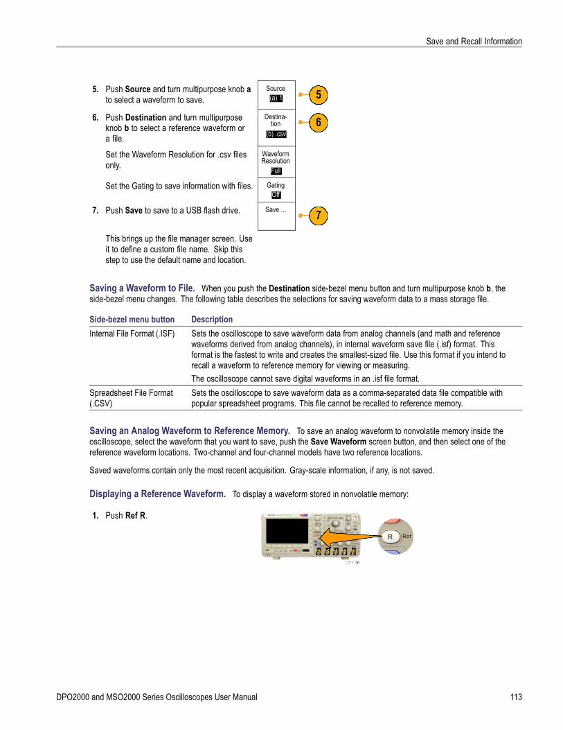
Save and Recall Information
5. Push Source and turn multipurpose knob ato select a waveform to save.
Source(a) 1
6. Push Destination and turn multipurposeknob b to select a reference waveform ora file.
Destina-tion
(b) .csv
Set the Waveform Resolution for .csv filesonly.
WaveformResolution
Full
Set the Gating to save information with files. GatingOff
7. Push Save to save to a USB flash drive. Save ...
This brings up the file manager screen. Useit to define a custom file name. Skip thisstep to use the default name and location.
Saving a Waveform to File. When you push the Destination side-bezel menu button and turn multipurpose knob b, theside-bezel menu changes. The following table describes the selections for saving waveform data to a mass storage file.
Side-bezel menu button DescriptionInternal File Format (.ISF) Sets the oscilloscope to save waveform data from analog channels (and math and reference
waveforms derived from analog channels), in internal waveform save file (.isf) format. Thisformat is the fastest to write and creates the smallest-sized file. Use this format if you intend torecall a waveform to reference memory for viewing or measuring.The oscilloscope cannot save digital waveforms in an .isf file format.
Spreadsheet File Format(.CSV)
Sets the oscilloscope to save waveform data as a comma-separated data file compatible withpopular spreadsheet programs. This file cannot be recalled to reference memory.
Saving an Analog Waveform to Reference Memory. To save an analog waveform to nonvolatile memory inside theoscilloscope, select the waveform that you want to save, push the Save Waveform screen button, and then select one of thereference waveform locations. Two-channel and four-channel models have two reference locations.
Saved waveforms contain only the most recent acquisition. Gray-scale information, if any, is not saved.
Displaying a Reference Waveform. To display a waveform stored in nonvolatile memory:
1. Push Ref R.
DPO2000 and MSO2000 Series Oscilloscopes User Manual 113

Save and Recall Information
2. Push R1 or R2. (R1) |(On) (R2) |(Off)
Removing a Reference Waveform from the Display. To remove a reference waveform from the display:
1. Push Ref R.
2. Push the R1 or R2 lower-bezel button toremove the reference waveform from thedisplay.
(R1) |(On) (R2) |(Off)
The reference waveform is still in nonvolatilememory and can be displayed again.
Saving and Recalling SetupsSetup information includes acquisition information, such as vertical, horizontal, trigger, cursor, and measurement information.It does not include communications information, such as GPIB addresses. To save the setup information:
1. Push Save / Recall Menu.
2. Push Save Setup or Recall Setup from thelower-bezel menu.
SaveScreenImage
SaveWaveform
SaveSetup
RecallWaveform
RecallSetup
Assign
Save| toSetup
FileUtilities
114 DPO2000 and MSO2000 Series Oscilloscopes User Manual
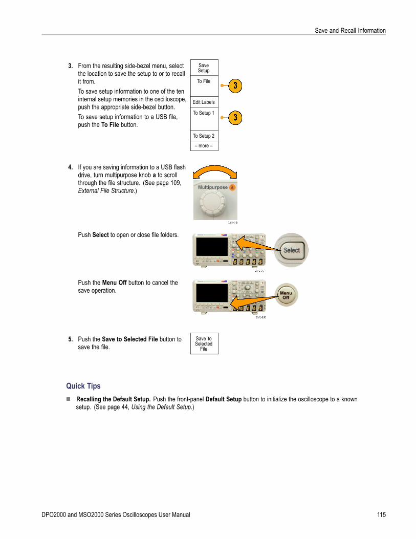
Save and Recall Information
SaveSetup
To File
Edit Labels
3. From the resulting side-bezel menu, selectthe location to save the setup to or to recallit from.To save setup information to one of the teninternal setup memories in the oscilloscope,push the appropriate side-bezel button.To save setup information to a USB file,push the To File button.
To Setup 1
To Setup 2
– more –
4. If you are saving information to a USB flashdrive, turn multipurpose knob a to scrollthrough the file structure. (See page 109,External File Structure.)
Push Select to open or close file folders.
Push the Menu Off button to cancel thesave operation.
5. Push the Save to Selected File button tosave the file.
Save toSelected
File
Quick TipsRecalling the Default Setup. Push the front-panel Default Setup button to initialize the oscilloscope to a knownsetup. (See page 44, Using the Default Setup.)
DPO2000 and MSO2000 Series Oscilloscopes User Manual 115
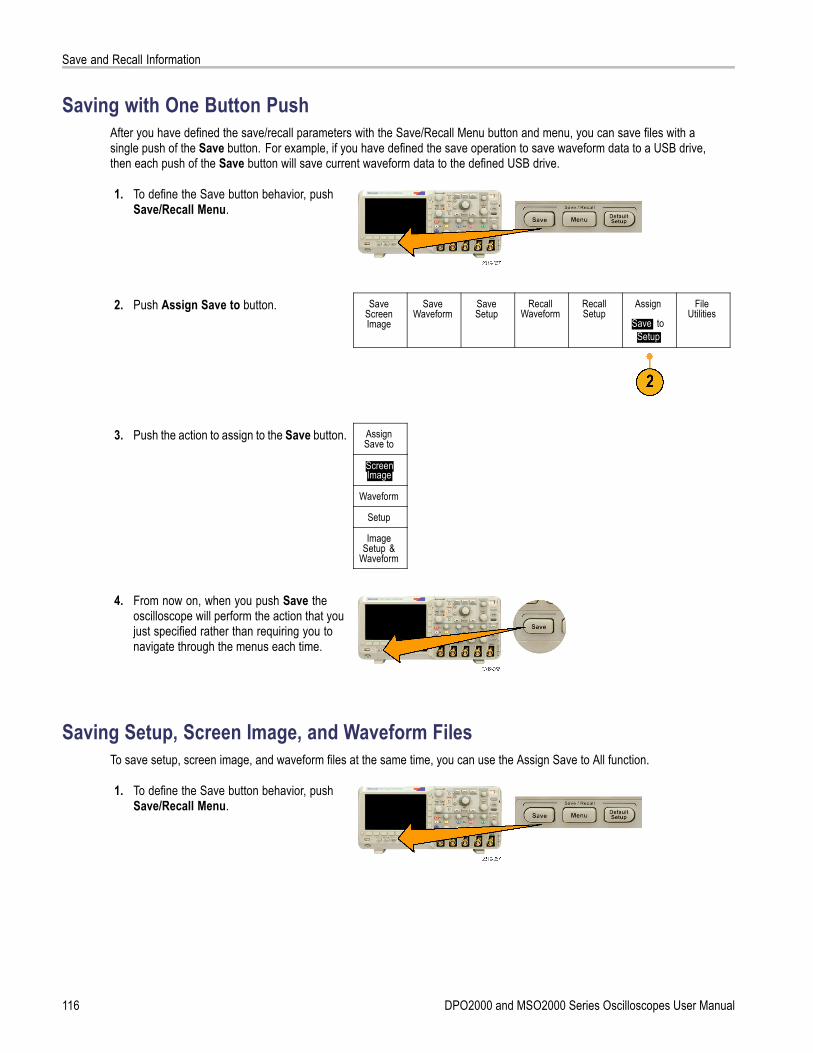
Save and Recall Information
Saving with One Button PushAfter you have defined the save/recall parameters with the Save/Recall Menu button and menu, you can save files with asingle push of the Save button. For example, if you have defined the save operation to save waveform data to a USB drive,then each push of the Save button will save current waveform data to the defined USB drive.
1. To define the Save button behavior, pushSave/Recall Menu.
2. Push Assign Save to button. SaveScreenImage
SaveWaveform
SaveSetup
RecallWaveform
RecallSetup
Assign
Save| toSetup
FileUtilities
3. Push the action to assign to the Save button. AssignSave to
ScreenImage
Waveform
Setup
ImageSetup &
Waveform
4. From now on, when you push Save theoscilloscope will perform the action that youjust specified rather than requiring you tonavigate through the menus each time.
Saving Setup, Screen Image, and Waveform FilesTo save setup, screen image, and waveform files at the same time, you can use the Assign Save to All function.
1. To define the Save button behavior, pushSave/Recall Menu.
116 DPO2000 and MSO2000 Series Oscilloscopes User Manual

Save and Recall Information
2. Push Assign Save to button. SaveScreenImage
SaveWaveform
SaveSetup
RecallWaveform
RecallSetup
Assign
Save| toSetup
FileUtilities
3. Push the Setup, Image & Waveform button. AssignSave to
ScreenImage
Waveform
Setup
Setup,Image &
Waveform
4. From now on, when you push Save theoscilloscope creates three files: setup,screen image, and waveform.
DPO2000 and MSO2000 Series Oscilloscopes User Manual 117
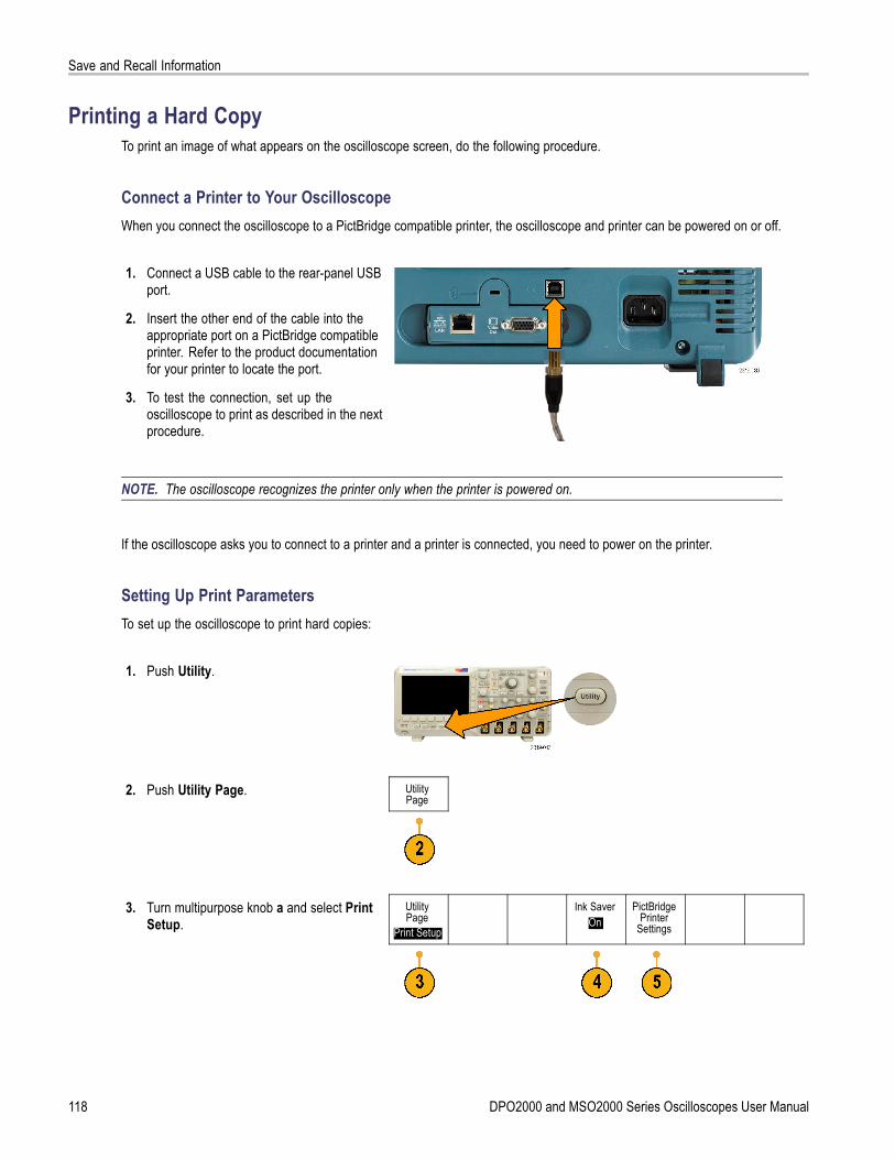
Save and Recall Information
Printing a Hard CopyTo print an image of what appears on the oscilloscope screen, do the following procedure.
Connect a Printer to Your OscilloscopeWhen you connect the oscilloscope to a PictBridge compatible printer, the oscilloscope and printer can be powered on or off.
1. Connect a USB cable to the rear-panel USBport.
2. Insert the other end of the cable into theappropriate port on a PictBridge compatibleprinter. Refer to the product documentationfor your printer to locate the port.
3. To test the connection, set up theoscilloscope to print as described in the nextprocedure.
NOTE. The oscilloscope recognizes the printer only when the printer is powered on.
If the oscilloscope asks you to connect to a printer and a printer is connected, you need to power on the printer.
Setting Up Print ParametersTo set up the oscilloscope to print hard copies:
1. Push Utility.
2. Push Utility Page. UtilityPage
3. Turn multipurpose knob a and select PrintSetup.
UtilityPage
Print Setup
Ink SaverOn
PictBridgePrinter
Settings
118 DPO2000 and MSO2000 Series Oscilloscopes User Manual
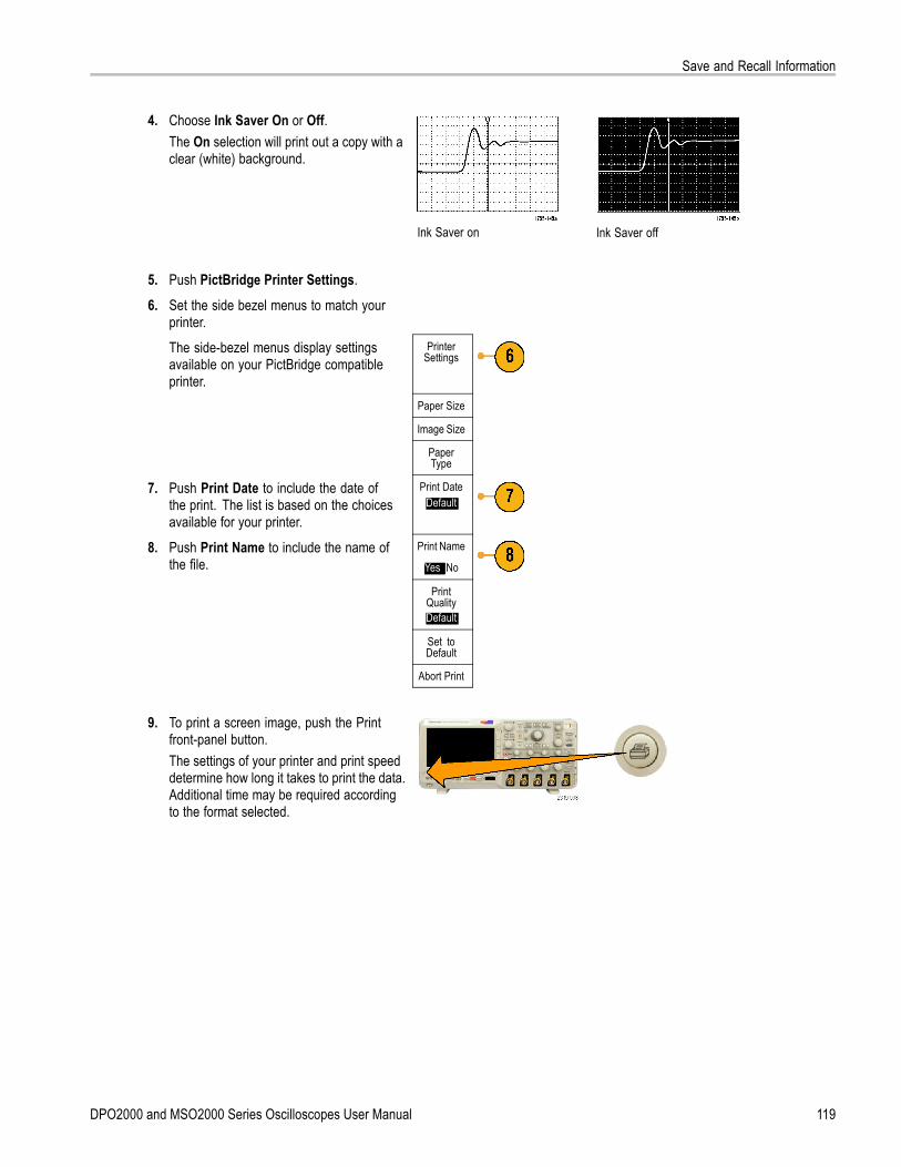
Save and Recall Information
4. Choose Ink Saver On or Off.The On selection will print out a copy with aclear (white) background.
Ink Saver on Ink Saver off
5. Push PictBridge Printer Settings.
6. Set the side bezel menus to match yourprinter.The side-bezel menus display settingsavailable on your PictBridge compatibleprinter.
PrinterSettings
Paper Size
Image Size
PaperType
7. Push Print Date to include the date ofthe print. The list is based on the choicesavailable for your printer.
Print DateDefault
8. Push Print Name to include the name ofthe file.
Print Name
Yes |No
PrintQualityDefault
Set toDefault
Abort Print
9. To print a screen image, push the Printfront-panel button.The settings of your printer and print speeddetermine how long it takes to print the data.Additional time may be required accordingto the format selected.
DPO2000 and MSO2000 Series Oscilloscopes User Manual 119

Save and Recall Information
10. If printing fails, check that the USB cableis connected to the PictBridge port on theprinter, and try again.
Quick TipsPush Set To Defaults to have the oscilloscope match the print settings to the default settings of your printer.
The oscilloscope displays an error message when the oscilloscope detects a mismatched setting. In some cases, theoscilloscope can correct the mismatch and will send the image to the printer, such as for mismatched paper sizes.
Printing with One Button PushOnce you have connected a printer to your oscilloscope and set up print parameters, you can print current screen imageswith a single push of a button:
Push the printer icon button in the lower leftcorner of the front panel.
Erasing Oscilloscope MemoryYou can erase all setup and waveform information saved in the nonvolatile oscilloscope memory with the TekSecure function.If you have acquired confidential data on your oscilloscope, you may want to execute the TekSecure function before youreturn the oscilloscope to general use. The TekSecure function:
Replaces all waveforms in all reference memories with null values
Replaces the current front-panel setup and all stored setups with the default setup
Displays a confirmation or warning message, depending on whether the verification is successful or unsuccessful
To use TekSecure:
1. Push Utility.
2. Push Utility Page. UtilityPage
120 DPO2000 and MSO2000 Series Oscilloscopes User Manual

Save and Recall Information
3. Turn multipurpose knob a and select Config. UtilityPageConfig
LanguageEnglish
Set Date &Time
TekSecureErase
Memory
About
4. Push TekSecure Erase Memory.
5. Push OK Erase Setup and Ref Memoryfrom the side-bezel menu.
OKEraseSetup& Ref
Memory
To cancel the procedure, push Menu Off.
6. Power off the oscilloscope, and then powerit back on to complete the process.
DPO2000 and MSO2000 Series Oscilloscopes User Manual 121
Using Application Modules
Using Application ModulesOptional application module packages extend the capability of your oscilloscope. (See page 14, Application Module FreeTrial.) You can install up to two application modules at one time. (See page 14, Installing an Application Module.)
Refer to the DPO2000 and MSO2000 Series Oscilloscopes Application Module Installation that came with your applicationmodule for instructions on installing and testing an application module. Some modules are described in the following list.Additional modules may be available. Contact your Tektronix representative or visit our Web site at www.tektronix.comfor more information.
The DPO2EMBD Embedded Serial Triggering and Analysis Module adds triggering on packet level information inserial buses used in embedded designs (I2C and SPI), as well as analytical tools to help you efficiently analyze yourserial bus. These include bus views, packet decoding, search tools, and event tables with timestamp information.
The DPO2AUTO Automotive Serial Triggering and Analysis Module adds triggering on packet level information inserial buses used in automotive designs (CAN and LIN), as well as analytical tools to help you efficiently analyze yourserial bus. These include bus views, packet decoding, search tools, and event tables with timestamp information.
The DPO2COMP Computer Serial Triggering and Analysis Module adds triggering on byte or packet level informationin RS-232, RS-422, RS-485, and UART buses, and analytical tools to help you efficiently analyze your serial bus. Theseinclude bus views, packet decoding, search tools, and event tables with timestamp information.
122 DPO2000 and MSO2000 Series Oscilloscopes User Manual

Appendix: Warranted Specifications, Safety Certifications, and Electromagnetic Compatibility
Appendix: Warranted Specifications, Safety Certifications, andElectromagnetic Compatibility
Analog bandwidth Oscilloscope 5 mV/div to 5 V/divwith an ambienttemperature of 0 °C to40 °C (0 °F to 104 °F)
5 mV/div to 5 V/divwith an ambienttemperature of 0 °C to50 °C (0 °F to 122 °F)
<5 mV/div
DPO2024,MSO2024
DC to ≥200 MHz DC to ≥160 MHz 20 MHz
DPO2014,MSO2014,DPO2012,MSO2012
DC to ≥100 MHz 20 MHz
Input impedance,DC coupled
1 MΩ ±2% in parallel with 11.5 pF ±2 pF
DC Balance ±(1 mV + 0.1 div)DC gain accuracy ±3%, 5 V/div through 10 mV/div
±4%, 5 mV/div and 2 mV/divOffset accuracy ± [0.01 × | offset – position | + DC Balance]
NOTE. Both the position and constant offset term must be converted to volts by multiplying by theappropriate volts/div term.
Long-term samplerate and delay timeaccuracy
±25 ppm over any >1 ms interval
Digital ChannelThreshold Accuracy,MSO2000 seriesonly
± [100 mV + 3% of the threshold setting after calibration]
DPO2000 and MSO2000 Series Oscilloscopes User Manual 123

Appendix: Warranted Specifications, Safety Certifications, and Electromagnetic Compatibility
124 DPO2000 and MSO2000 Series Oscilloscopes User Manual
Index
Index
AAbout, 21Accessories, 1Acquire button, 29, 48, 76Acquisition
input channels anddigitizers, 46
modes defined, 48readout, 35sampling, 46
AdapterTEK-USB-488, 3TPA-BNC, 3, 8
Adding waveform, 76Altitude
DPO2000 and MSO2000, 5P6316, 6
Amplitude measurement, 89Annotating the screen, 86Application modules, 14, 122
30-day free trial, 14DPO2AUTO, 3, 51DPO2COMP, 3, 51DPO2CONN, 3, 22DPO2EMBD, 3, 51
Area measurement, 90Attenuation, 82Auto trigger mode, 65Autoset, 45
Video, 46Autoset button, 12, 29, 33, 41, 45Autoset disable, 45Autoset undo, 45Aux In connector, 39Auxiliary readout, 37Average acquisition mode, 48
BB1 / B2 button, 31, 51, 52, 70Backlight intensity, 79Bandwidth, x, 81Baseline indicators, 38Before Installation, 1Blackman-Harris FFT window, 101Blue lines, 85BNC interface, 9Burst Width measurement, 89
Busbutton, 51, 52, 70display, 38, 54menu, 31, 52positioning and labeling, 83setup, 52
Bus and Waveforms displayshow physical layer bus
activity, 59Bus trigger, defined, 70Buses, 51, 70
cursor readout, 96
ButtonAcquire, 29, 48, 76Autoset, 12, 29, 33, 41, 45B1 / B2, 51, 70B1 / B2 bus, 52B1, B2, 31bus, 51, 52, 70Channel, 30Cursors, 31, 94D15 - D0, 34Default Setup, 34, 41, 44FilterVu, 32Fine, 29, 31, 32, 33Force Trig, 33, 65, 67hard copy, 34, 120Intensity, 79M, 31, 97, 98Math, 31, 97, 98Measure, 29, 87, 91Menu Off, 34Next, 33Play-pause, 32, 104Previous, 33Print, 34printer, 120Push Level to Set 50%, 33Ref, 31, 101, 113Run/Stop, 33, 50, 75Save / Recall, 29, 34, 111Search, 29, 106Select, 32Set / Clear Mark, 33, 105Single, 33, 75Test, 29Trigger, 29Trigger level, 33Trigger menu, 68Utility, 14, 15, 17, 29, 77, 78,
86, 118Vertical, 30Zoom, 32
byte matching, 74
CCalibration, 17, 18Calibration certificate, 1CAN, 31, 51, 70CAN trigger, 73
DPO2000 and MSO2000 Series Oscilloscopes User Manual 125

Index
Channel button, 30Channel readout, 38Channel vertical menu, 81Cleaning, 7Clearance, DPO2000 and
MSO2000, 5Communications, 21, 24Compensate probe, 12Compensate signal path, 17Confidential data, 120Connecting a USB keyboard, 25Connecting to a PC, 21Connectivity, 1, 21, 24Connectors
front-panel, 39rear-panel, 40side-panel, 39
Controls, 27Coupling, 81Coupling, trigger, 66Cross Hair graticule style, 78CSV format, 113Cursor readout, 36, 96Cursors, 94
button, 31, 94linking, 95measurements, 94menu, 94XY, 97
Cycle Area measurement, 90Cycle Mean measurement, 90Cycle RMS measurement, 90
DD15 - D0 button, 34Date and time, changing, 15Default Setup, 44, 115
button, 34, 41, 44menu, 34Undo, 44
Delay measurement, 88Delay time, 50Depth, DPO2000 and MSO2000, 5Deskew, 82Deskew pulse generator and signal
source, 3Digital channels, 85
Baseline indicators, 38scaling, positioning, grouping,
and labeling, 83setup, 60
Digital probe interface, 9
Disable Autoset, 45Display
information, 35persistence, 76style, 76XY, 77
Displaying, referencewaveforms, 113
DPO2AUTO, 3, 51, 122DPO2COMP, 3, 51, 122DPO2CONN, 3, 22DPO2EMBD, 3, 51, 122Drivers, 21, 23Dual waveform math, 97
Ee*Scope, 24Edge trigger, defined, 68Edges
Fuzzy, 86White, 85
Erase setup and ref memory, 120Ethernet, x, 23, 24
port, 40event, 33Event Table, 54Excel, 21Expansion point, 47Expansion point icon, 36
FFactory calibration, 18Fall Time measurement, 88Falling Edge Count
measurement, 90FFT
Blackman-Harris, 101controls, 98Hamming, 100Hanning, 100Rectangular, 100
File format, 112Internal File Format (ISF), 113Spreadsheet file format
(.CSV), 113File names, 109File system, 109, 113FilterVu, 36, 61FilterVu button, 32FilterVu Glitch Capture acquisition
mode, 48
FilterVu Noise Filter acquisitionmode, 48
Fine, 32Fine button, 29, 31, 32, 33Firmware upgrade, 18Firmware version, 21firmware.img file, 18Force Trig button, 33, 65, 67Frame graticule style, 78Frequency measurement, 88Frequency, Source
DPO2000 and MSO2000, 5Front panel, 27Front-panel connectors, 39Front-panel overlay, 15Full graticule style, 78Functional check, 11Fuzzy edges, 86
GGating, 91GPIB, 22GPIB address, 23Graticule
Cross Hair, 78Frame, 78Full, 78Grid, 78intensity, 79IRE, 78mV, 78styles, 77
Green lines, 85Grid graticule style, 78Ground, 10Ground lead, 13Ground strap, 10Ground strap connector, 39Ground yourself to discharge
static, 10Grouping channels, 61
digital, 83
HHamming FFT window, 100Hanning FFT window, 100Hard copy, 118Hard copy button, 34Height, DPO2000 and MSO2000, 5High measurement, 89High-low indicators, 38
126 DPO2000 and MSO2000 Series Oscilloscopes User Manual
Index
Holdoff, trigger, 66Horizontal delay, 66Horizontal lines
Green and blue, 85Horizontal position, 33, 47, 66, 67,
80, 100and math waveforms, 98defined, 42readout, 37
Horizontal scale, 33, 80, 100and math waveforms, 98defined, 42readout, 37
How tocompensate a voltage
probe, 12compensate the signal path, 17connect probes and
adapters, 8connect to a computer, 21erase memory, 120label channels and buses, 42manage long record length
waveforms, 103perform a functional check, 11power off the oscilloscope, 11power on the oscilloscope, 10print a hard copy, 118recall setups, 114recall waveforms, 111save screen images, 111save setups, 114save waveforms, 111search through and add marks
to waveforms, 105select a trigger, 68select automatic
measurements, 88setup analog channels, 41setup bus parameters, 52setup digital channels, 60setup input parameters, 81setup VISA communica-
tions, 21take automatic
measurements, 87take manual measurements
with cursors, 94trigger on buses, 70upgrade the firmware, 18use e*Scope, 24use FilterVu, 63use Wave Inspector, 103
HumidityDPO2000 and MSO2000, 5P2221, 6P6316, 7
II2C, 31, 51, 70
trigger, 72Icon
Expansion point, 36Trigger level, 37Trigger position, 36
Indicator, waveform baseline, 38Infinite persistence, 77Ink Saver, 112, 119Inner knob, 32, 98Input capacitance, P6316, 6Input resistance, P6316, 6Intensity button, 79Internal File Format (ISF), 113Invert, 81IRE graticule, 78ISF format, 113
KKeyboard, USB, 25Knob
inner, 32, 98Multipurpose, 16, 29, 32, 48,
113outer, 32pan, 32, 104, 105Trigger level, 67Vertical menu, 33Vertical position, 33, 42Vertical scale, 34, 42zoom, 32, 98, 103
LLabel bus, 83LabView, 21LabVIEW, 1LAN port, 40Language
change, 14overlay, 15
Level, trigger, 67LIN, 31, 51, 70
trigger, 73Lock, standard laptop, 9
Logic trigger, defined, 69Long record length
management, 103Low measurement, 89
MM button, 31, 97, 98Mark, 105Math
button, 31, 97, 98Dual waveform, 97FFT, 98menu, 31waveforms, 97
Max measurement, 89Maximum nondestructive input
signal, P6316, 6Mean measurement, 90Measure button, 29, 87, 91Measurement menu, 29Measurements
automatic, 87cursor, 94defined, 88reference levels, 93snapshot, 91
Memory, erasure of, 120Menu, 27
Bus, 31, 52buttons, 29Cursors, 94Default Setup, 34Math, 31Measurement, 29Reference, 31, 101, 102Save / Recall, 29, 34, 111Trigger, 29, 68Utility, 14, 16, 29, 34, 77, 86,
118Vertical, 30, 81
Menu Off button, 34Min measurement, 89Minimum signal swing, P6316, 6Mode, roll, 50Multiple transition detection, 85Multipurpose knob, 29, 32, 48, 113mV graticule, 78
NNegative Duty Cycle
measurement, 88
DPO2000 and MSO2000 Series Oscilloscopes User Manual 127

Index
Negative Overshootmeasurement, 90
Negative Pulse Countmeasurement, 90
Negative Pulse Widthmeasurement, 88
Next button, 33NI LabVIEW SignalExpress Tektronix
Edition software, xNormal trigger mode, 65
OOffset and position, 82Offset vertical, 82OpenChoice Desktop PC
Communications, x, 1Operating specifications, 5Oscilloscope
connecting to a printer, 118Outer knob, 32Overlay, 15
PP2221 probe, 2P6316 probe, 2, 61P6316 probe ground leads, 60Pan, 103, 104
knob, 32, 104, 105Parallel bus, x, 51, 70Parallel bus trigger, 70, 71Pause, 104Peak Detect acquisition mode, 48Period measurement, 88Persistence
display, 76infinite, 77variable, 77
Phase measurement, 88Physical layer bus activity, 59PictBridge, x, 23Pk-Pk measurement, 89Play, 104Play-pause button, 32, 104Play-pause mode, 104Pollution Degree
DPO2000 and MSO2000, 6P2221, 6P6316, 6
Positionbus, 83digital channels, 83Horizontal, 66, 67, 80, 100Vertical, 80
Position and offset, 82Positive Duty Cycle
measurement, 88Positive Overshoot
measurement, 89Positive Pulse Count
measurement, 90Positive Pulse Width
measurement, 88Posttrigger, 65, 67Power
cord, 2input, 40off, 11removing, 11supply, 10switch, 34
Power consumption, DPO2000 andMSO2000, 5
Power measurement deskew andcalibration fixture, 3
Predefined math expressions, 97Pretrigger, 65, 67Previous button, 33Print, 118
hard copy, 118Print button, 34Printer
connecting, 118PictBridge compatible, 118
Probe Comp, 12PROBE COMP connector, 39Probe compensation, 12Probe connector
analog, 39digital, 39
ProbesBNC, 9connecting, 8digital, 9ground lead, 13P2221, 2P6316, 2TEK-USB-488 Adapter, 3TekVPI, 8TPA-BNC Adapter, 3, 8
Pulse Width trigger, defined, 69Push Level to Set 50% button, 33
RRackmount, 3Readout
Acquisition, 35Auxiliary, 37Channel, 38Cursor, 36, 96Horizontal position/scale, 37Timing resolution, 38Trigger, 37, 74Trigger status, 36
Real-time sampling, 47Rear-panel connectors, 40Recalling
setups, 114waveforms, 111
Record length, x, 47Rectangular FFT window, 100Ref button, 31, 101, 113Ref R, 113Reference levels, 93Reference menu, 31, 101, 102Reference waveforms, 101
displaying, 113removing, 102, 114saving, 113
Removing referencewaveforms, 102, 114
Removing waveform, 76Rise Time measurement, 88Rise/Fall trigger, defined, 70Rising Edge Count
measurement, 90RMS measurement, 90Roll mode, 50Rolling window data matching, 73RS-232, 31, 51, 70
byte matching, 74cursor readout, 96decoding, 59trigger, 73
Run/Stop button, 33, 50, 75Runt trigger, defined, 69
SSafety Summary, iiiSample acquisition mode, 48Sample interval, 47Sample rates, xSampling process, defined, 46Sampling, real-time, 47Save / Recall menu, 29, 34, 111
128 DPO2000 and MSO2000 Series Oscilloscopes User Manual
Index
Save / Recall Menu button, 29Save / Recall Save button, 34, 111Save All, 116Saving
reference waveforms, 113screen images, 111setups, 114waveforms, 111
Saving and recallingInformation, 109
Scaledigital channels, 83Horizontal, 33, 80, 100Vertical, 80
Screen annotations, 86Search, 105Search button, 29, 106Securing memory, 120Security lock, 9Select button, 32Serial bus, 51Serial bus trigger, 70Set / Clear Mark button, 33, 105Setup
default, 34, 41, 44, 115Setup and Hold trigger, defined, 69Side panel connector, 39Signal path compensation, 17Single button, 33, 75Single sequence, 50, 75Slope, trigger, 67Snapshot, 91Software drivers, 21, 23Software, optional, 122SPC, 17Specifications
operating, 5power supply, 10
SPI, 31, 51, 70SPI trigger, 72Spreadsheet file format (.CSV), 113Start an acquisition, 75Stop an acquisition, 75Switch, power, 34
TTable, Event, 54TEK-DPG, 3TEK-DPG converter, 3TEK-USB-488 Adapter, 3, 22, 23TekSecure, 120TekVPI, 8
TekVPI external power adapter, 3Temperature
DPO2000 and MSO2000, 5P2221, 6P6316, 6
Test button, 29Threshold accuracy, P6316, 6Threshold range, P6316, 6Timing resolution readout, 38TPA-BNC Adapter, 3, 8Transit case, 3Transition trigger, defined, 70Trigger
Bus, defined, 70buses, 70byte matching, 74CAN bus, 73concepts, 65coupling, 66data matching on a rolling
window, 73Edge, defined, 68event, defined, 65forcing, 65holdoff, 66I2C bus, 72level, 67level button, 33level icon, 37level knob, 33, 67LIN bus, 73Logic, defined, 69modes, 65, 68parallel bus data matching, 74parallel buses, 51, 71point, 47position icon, 36posttrigger, 65, 67pretrigger, 65, 67Pulse Width, defined, 69readout, 37, 74Rise/Fall, defined, 70RS-232 bus, 73RS-232 byte matching, 74Runt, defined, 69serial buses, 51, 71Setup and Hold, defined, 69slope, 67SPI bus, 72status readout, 36Video, defined, 70
Trigger menu, 29, 68button, 68
Trigger modesAuto, 65Normal, 65
Trigger types, defined, 68Triggering on Buses, 70
UUndo
Autoset, 45Default Setup, 44
Upgrading firmware, 18USB, 22, 29, 109
Device port, x, 40Host port, xHost ports, 34keyboard, 25
USB Device port, 23USB Host port, 23User marks, 105Utility button, 14, 15, 17, 29, 77, 78,
86, 118Utility menu, 14, 16, 29, 34, 77, 86
VVariable persistence, 77Versatile Probe Interface, 8Version, firmware, 21Vertical
button, 30menu, 30, 81Menu knob, 33offset, 82Offset, 82position, 80position and autoset, 46position and offset, 82Position knob, 33, 42scale, 80Scale knob, 34, 42
VibrationDPO2000 and MSO2000, 6
VideoAutoset, 46
Video Out, xport, 40
Video trigger, defined, 70View
digital channels, 85waveform record, 36
VISA, 21
DPO2000 and MSO2000 Series Oscilloscopes User Manual 129

Index
Voltage, InputP2221, 6
Voltage, SourceDPO2000 and MSO2000, 5
WWave Inspector, x, 103
Waveformadding, 76display style, 76intensity, 79pan, 103, 104pause, 104play, 104play-pause, 104record defined, 47removing, 76search and mark, 105user marks, 105zoom, 103
Waveform baseline indicator, 38Waveform record, 47Waveform record view, 36Weight
DPO2000 and MSO2000, 5White edges, 85
WidthDPO2000 and MSO2000, 5
XXY
cursors, 97display, 77
ZZoom, 103
button, 32graticule size, 104knob, 32, 103
130 DPO2000 and MSO2000 Series Oscilloscopes User Manual