Embed Size (px)
Citation preview

Volume No: 2 (2015), Issue No: 6 (June) June 2015 www.ijmetmr.com Page 330
ISSN No: 2348-4845International Journal & Magazine of Engineering,
Technology, Management and ResearchA Peer Reviewed Open Access International Journal
K.L.OmprakashAssistant Professor,
Tirumala Engineering College.
B.RajeshAssistant Professor,
Ananthalakshmi Engineering College.
This situation started the growth of decentralized elec-tricity generation (using renewable energy resources). UPFC enable the operation of power transmission net-works near their maximum ratings, by enforcing power flow through well-defined lines. These days, UPFCs are one of the most versatile and powerful FACTS devices.The UPFC results from the combination of a STATCOM and a SSSC that shares a common dc capacitor link. The existence of a dc capacitor bank originates additional losses, decreases the converter lifetime, and increases its weight, cost, and volume.
In the last few decades, an increasing interest in new converter types, capable of performing the same func-tions but with reduced storage needs, has arisen. These converters are capable of performing the same ac/ac conversion, allowing bidirectional power flow, guaran-teeing near sinusoidal input and output currents, volt-ages with variable amplitude, and adjustable power factor. These minimum energy storage ac/ac convert-ers have the capability to allow independent reactive control on the UPFC shunt and series converter sides, while guaranteeing that the active power exchanged on the UPFC series connection is always supplied/ab-sorbed by the shunt connection.
Conventional UPFC controllers do not guarantee ro-bustness. In, the dependence of the matrix converter output voltage on the modulation coefficient was ana-lyzed, concluding that Matrix Converter -UPFC is able to control the full range of power flow. Recent non-linear approaches enabled better tuning of PI control-ler parameters. Still, there is room to further improve the dynamic response of UPFCs, using nonlinear robust controllers.
EXISTING SYSTEM LIMITATIONS:
Conventional UPFC controllers do not guarantee ro-bustness.
Abstract:
Power control, broadly speaking, is the intelligent se-lection of transmitter power output in a communica-tion system to achieve good performance within the system. In this paper, a matrix converter- based UPFC is proposed, using a direct power control approach (DPC-MC) based on an MC-UPFC dynamic model. In or-der to design UPFCs, presenting robust behavior to pa-rameter variations and to disturbances, the proposed DPC-MC control method, is based on sliding mode-control techniques, allowing the real-time selection of adequate matrix vectors to control input and output electrical power. By selecting an appropriate matrix converter switching state, line active and reactive pow-er, together with ac supply reactive power, can be di-rectly controlled, and guaranteeing good steady-state and dynamic responses.
The line active and reactive power linear controllers based on a modified Venturini highfrequency PWM modulator compared with direct power controller (DPC) by using MC-UPFC; guarantee faster responses without overshoot, presenting no cross-coupling in dy-namic and steady- state responses and no steady state error. Experimental results of direct power controllers for MC based UPFC shows decoupled active and reac-tive power control and fast response times.
Keywords:
DPC, UPFC, MC, reactive power, Power control.
Introduction:
In the last few years, electricity market deregulation, together with growing economic, environmental, and social concerns, has increased the difficulty to burn fos-sil fuels, and to obtain new licenses to build transmis-sion lines (rights-of-way) and high-power facilities.
DPC Method for Three-Phase Matrix Converters Operating as Unified Power Flow Controllers (UPFCs)

Volume No: 2 (2015), Issue No: 6 (June) June 2015 www.ijmetmr.com Page 331
ISSN No: 2348-4845International Journal & Magazine of Engineering,
Technology, Management and ResearchA Peer Reviewed Open Access International Journal
The existence of a dc capacitor bank originates addi-tional losses, decreases the converter lifetime, and in-creases its weight, cost, and volume. Minimum Storage Capability and Conventional UPFC controllers do not guarantee robustness.
PROPOSED SYSTEM MERITS:
Unified power-flow controllers (UPFC) enable the op-eration of power transmission networks near their maximum ratings, by enforcing power flow through well-defined lines.MC-based UPFC (MC-UPFC) has reduced volume and cost, reduced capacitor power losses, together with higher reliability. As a result, line active and reactive power, together with ac supply re-active power, can be directly controlled by selecting an appropriate matrix converter switching state guaran-teeing good steady-state and dynamic responses.
APPLICATIONS:
•Many Power Applications,•It’s controlled the input and Output Electrical Powers (ex. Transformers.)•Transmission line Power Control as well as Power Fac-tor Control.
UNIFIED POWER FLOW CONTROLLER:
Gyugyi proposed the UPFC concept in 1991. The UPFC was devised for the real time control and dynamic compensation of ac transmission systems, providing multifunctional flexibility required to solve many of the problems facing the delivery industry. Within the frame-work of traditional power transmission concepts, the UPFC is able to control, simultaneously or selectively.
MATRIX CONVERTER:
The matrix converter has several advantages over tra-ditional rectifier-inverter type power Frequency con-verters. It provides sinusoidal input and output wave-forms, with minimal higher Order harmonics and no sub harmonics; it has inherent bi-directional energy flow capability; the Input power factor can be fully controlled. Last but not least, it has minimal energy storage Requirements, which allows to get rid of bulky and lifetime- limited energy-storing capacitors. But the matrix converter has also some disadvantages.
First of all it has a maximum input output Voltage trans-fer ratio limited to 87 % for sinusoidal input and output waveforms. It requires more semiconductor devices than a conventional AC-AC indirect power frequency Converter, since no monolithic bi-directional switches exist and consequently discrete unidirectional devices, variously arranged, have to be used for each bi-direc-tional switch. Finally, it is particularly sensitive to the disturbances of the input voltage system.The com-ments and remarks made in this chapter are some-where supported by simulation Results.
All the parameters affecting power flow in the trans-mission line (i.e., voltage, impedance and phase angle), and this unique capability is signed by the adjective “unified” in its name. Alternatively, it can independent-ly control both the real and reactive power flows in the line.
The UPFC is a combination of a static compensator and static series compensation. It acts as a shunt compen-sating and a phase shifting device simultaneously.
Circuit scheme of a three phase to three phase matrix converter. a, b, c are at the input terminals. A, B, C are at the output terminals.

Volume No: 2 (2015), Issue No: 6 (June) June 2015 www.ijmetmr.com Page 332
ISSN No: 2348-4845International Journal & Magazine of Engineering,
Technology, Management and ResearchA Peer Reviewed Open Access International Journal
The UPFC consists of a shunt and a series transformer, which are connected via two voltage source convert-ers with a common DC-capacitor. The DC-circuit allows the active power exchange between shunt and series transformer to control the phase shift of the series voltage.
OPERATING PRINCIPLE OF UPFC:The basic components of the UPFC are two voltage source inverters (VSIs) sharing a common dc storage capacitor, and connected to the power system through coupling transformers. One VSI is connected to in shunt to the transmission system via a shunt transformer, while the other one is connected in series through a series transformer.
Principle configuration of an UPFC
Transmission network with matrix converter UPFC.
Basic schematic diagram of UPFCA basic UPFC functional scheme is shown in above Figure. The series inverter is controlled to inject a symmetrical three phase voltage system (Vse), of controllable magnitude and phase angle in series with the line to control ac-tive and reactive power flows on the transmission line. So, this inverter will exchange active and reactive power with the line.
MODELING OF MC UPFCGeneral Architecture:

Volume No: 2 (2015), Issue No: 6 (June) June 2015 www.ijmetmr.com Page 333
ISSN No: 2348-4845International Journal & Magazine of Engineering,
Technology, Management and ResearchA Peer Reviewed Open Access International Journal
A simplified power transmission network using the proposed matrix converter UPFC is presented in the above figure, where VS and VR are, respectively, the sending-end and receiving-end sinusoidal voltages of the GS and GR generators feeding load ZL. The matrix converter is connected to transmission line 2, repre-sented as a series inductance with series resistance (L2 and R2), through coupling transformers T1and T2.
Below figure shows the simplified three-phase equiva-lent circuit of the matrix UPFC transmission system model. For system modeling, the power sources and the coupling transformers are all considered ideal. Also, the matrix converter is considered ideal and rep-resented as a controllable voltage source, with ampli-tude VC and phase. In the equivalent circuit, VR0 is the load bus voltage. The DPC-MC controller will treat the simplified elements as disturbances.
Three-phase equivalent circuit of the matrix UPFC and transmission line.
Considering a symmetrical and balanced three-phase system and applying Kirchhoff laws to the three-phase equivalent circuit as shown in Fig5.2, the ac line cur-rents are obtained in dq coordinates.
The active and reactive power of sending end genera-tor [19] are given in coordinates by
Assuming VRod and Vsd = Vd as constants and a rotat-ing reference frame synchronized to the Vs source so that Vsq= 0, active and reactive power P and Q are giv-en by (4) and (5), respectively
Based on the desired active and reactive power (Pref, Qref), reference currents (Idref, Iqref) can be calculat-ed from (4) and (5) for current controllers. However, allowing P,Q actual powers are sensitive to errors in the Vd, Vq values.
Control scheme of direct power control of the three-phase matrix converter operating as a UPFC.
IMPLEMENTATION OF THE DPC-MC AS UPFC:

Volume No: 2 (2015), Issue No: 6 (June) June 2015 www.ijmetmr.com Page 334
ISSN No: 2348-4845International Journal & Magazine of Engineering,
Technology, Management and ResearchA Peer Reviewed Open Access International Journal
As shown in the above Fig, the control of the instanta-neous active and reactive powers requires the measure-ment of Gs voltages and output currents necessary to calculate Sα(ep, t) and Sβ(eQ, t) and sliding surfaces. The output currents measurement is also used to de-termine the location of the input currents component. The control of the MC input reactive power requires the input currents measurement to calculate SQi(eQi, t) .
Results:
Fig. Results 1 - (a) and (b) shows, respectively, the sim-ulation results for the active and reactive power step response (Δ Pref = +0.4 p.u. and Δ Qref =+ 0.2 p.u.) and shunt reactive power, considering initial reference val-ues: Pref = 0.4 p.u., Qref = 0.2 p.u., and Qref = -0.07 p.u. Both results clearly show that there is no cross-cou-pling between active and reactive power.
Volume No: 2 (2015), Issue No: 6 (June) June 2015 www.ijmetmr.com Page 335
ISSN No: 2348-4845International Journal & Magazine of Engineering,
Technology, Management and ResearchA Peer Reviewed Open Access International Journal
(a)
(b)Fig Result 1: Power Response for P and Q step (Pref = +0.4 and Qref=+0.2)
(a) Active and reactive series power response ` (b) Reactive shunt power

Volume No: 2 (2015), Issue No: 6 (June) June 2015 www.ijmetmr.com Page 334
ISSN No: 2348-4845International Journal & Magazine of Engineering,
Technology, Management and ResearchA Peer Reviewed Open Access International Journal
As shown in the above Fig, the control of the instanta-neous active and reactive powers requires the measure-ment of Gs voltages and output currents necessary to calculate Sα(ep, t) and Sβ(eQ, t) and sliding surfaces. The output currents measurement is also used to de-termine the location of the input currents component. The control of the MC input reactive power requires the input currents measurement to calculate SQi(eQi, t) .
Results:
Fig. Results 1 - (a) and (b) shows, respectively, the sim-ulation results for the active and reactive power step response (Δ Pref = +0.4 p.u. and Δ Qref =+ 0.2 p.u.) and shunt reactive power, considering initial reference val-ues: Pref = 0.4 p.u., Qref = 0.2 p.u., and Qref = -0.07 p.u. Both results clearly show that there is no cross-cou-pling between active and reactive power.
Volume No: 2 (2015), Issue No: 6 (June) June 2015 www.ijmetmr.com Page 335
ISSN No: 2348-4845International Journal & Magazine of Engineering,
Technology, Management and ResearchA Peer Reviewed Open Access International Journal
(a)
b)Fig Result-2: (a) Line currents (IA, iB)
(b) Input matrix converter currents (ib, ic) p.u.DPC simulation results presented in Fig.(a) and (b), showing the claimed DPC faster dynamic response to step
active and reactive power reference change.
Volume No: 2 (2015), Issue No: 6 (June) June 2015 www.ijmetmr.com Page 336
ISSN No: 2348-4845International Journal & Magazine of Engineering,
Technology, Management and ResearchA Peer Reviewed Open Access International Journal
Volume No: 2 (2015), Issue No: 6 (June) June 2015 www.ijmetmr.com Page 337
ISSN No: 2348-4845International Journal & Magazine of Engineering,
Technology, Management and ResearchA Peer Reviewed Open Access International Journal
(a)
(a)
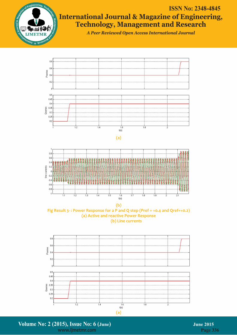
(b)Fig Result 3- : Power Response for a P and Q step (Pref = +0.4 and Qref=+0.2)
(a) Active and reactive Power Response (b) Line currents

Volume No: 2 (2015), Issue No: 6 (June) June 2015 www.ijmetmr.com Page 336
ISSN No: 2348-4845International Journal & Magazine of Engineering,
Technology, Management and ResearchA Peer Reviewed Open Access International Journal
Volume No: 2 (2015), Issue No: 6 (June) June 2015 www.ijmetmr.com Page 337
ISSN No: 2348-4845International Journal & Magazine of Engineering,
Technology, Management and ResearchA Peer Reviewed Open Access International Journal
(b)
(a)
(b)Fig Result-4: Power Response for a P and Q step (Pref = +0.4 and Qref=+0.2)
(a) Active and reactive Series power response (b) Line currents under linear controller
DPC controller ability to operate at lower switching frequencies, the DPC gains were lowered and the input filter parameters were changed accordingly (r=25Ω, l=5.9 mH C=12.6μF) to lower the switching frequency to nearly 1.4 kHz. The results (Fig.6.6) also show fast response without cross coupling between active and reactive power. This confirms the DPC-MC robustness to input filter parameter variation, the ability to operate at low switching frequencies, and insensitivity to switching nonlinearity.

Volume No: 2 (2015), Issue No: 6 (June) June 2015 www.ijmetmr.com Page 338
ISSN No: 2348-4845International Journal & Magazine of Engineering,
Technology, Management and ResearchA Peer Reviewed Open Access International Journal
CONCLUSION:
This project includes advanced nonlinear direct power controllers, for matrix converters connected to power transmission lines as UPFCs. Presented simulation and experimental results show that active and reactive power flow can be advantageously controlled by us-ing the proposed DPC. Results show no steady-state errors, no cross-coupling, insensitivity to non modeled dynamics and fast response times, thus confirming the expected performance of the presented nonlinear DPC methodology.
Despite showing a suitable dynamic response, the PI performance is inferior when compared to DPC. Fur-thermore, the PI controllers and modulator take lon-ger times to compute. Obtained results show that DPC is a strong nonlinear control candidate for line active and reactive power flow.
REFERENCES:
[1] N. Hingorani and L. Gyugyi, Understanding FACTS—Concepts and Technology of Flexible AC Transmis-sion Systems. Piscataway, NJ: IEEE Press/Wiley, 2000.
[2] L. Gyugyi, “Unified power flow control concept for flexible AC transmission systems,” Proc. Inst. Elect. Eng. C, vol. 139, no. 4, Jul. 1992.
[3] L. Gyugyi, C. Schauder, S. Williams, T. Rietman, D. Torgerson, and A. Edris, “The unified power flow con-troller: A new approach to power transmission con-trol,” IEEE Trans. Power Del., vol. 10, no. 2, pp. 1085–1097, Apr. 1995.
[4] C. Schauder, L. Gyugyi, M. Lund, D. Hamai, T. Ri-etman, D. Torgerson, and A. Edris, “Operation of the unified power flow controller (UPFC) under practical constraints,” IEEE Trans. Power Del., vol. 13, no. 2, pp. 630–639, Apr. 1998.
[5] T. Ma, “P-Q decoupled control schemes using fuzzy neural networks for the unified power flow control-ler,” in Electr. Power Energy Syst.. New York: Elsevier, Dec. 2007, vol. 29, pp. 748–748.
[6] L. Liu, P. Zhu, Y. Kang, and J. Chen, “Power-flow control performance analysis of a unified power-flow controller in a novel control scheme,” IEEE Trans. Pow-er Del., vol. 22, no. 3, pp. 1613–1619, Jul. 2007.
[7] F. Gao and M. Iravani, “Dynamic model of a space vector modulated matrix converter,” IEEE Trans. Pow-er Del., vol. 22, no. 3, pp. 1696–1750, Jul. 2007.
[8] B. Geethalakshmi and P. Dananjayan, “Investigation of performance of UPFC without DC link capacitor,” in Elect. Power Energy Res.. New York: Elsevier, 2008, pp. 284–294, 736-746.
About Author’s:
K L Omprakash, Born In 1988, Received The B.Tech Degree In Electrical Engineering From The Unives-ity Jntu Hyderabad In 2010 And The M.Tech Degree In Electrical Power System From The Institute Of Anna-macharya Institute Of Technology And Science Under The University Of Jntu Hyderabad In 2013, Currently Working As A Assistant Professor In Tirumala Engineer-ing College Under The University Of Jntu Hyderabad. Interested Area Machines, Power Systems And Mea-surments. .B Rajesh, Born In 1989, Received The B.Tech De-gree In Electrical Engineering From The Univesity Jntu Hyderabad In 2010 And The M.Tech Degree In Electri-cal Power System From The Institute Of ST.Maries In-stitute Of Technology And Science Under The Univer-sity Of Jntu Hyderabad In 2012, Currently Working As A Assistant Professor In Ananthalakshmi Engineering College Under The University Of Jntu Anantapur. Inter-ested Areas Power Systems And Measurments.
Volume No: 2 (2015), Issue No: 6 (June) June 2015 www.ijmetmr.com Page 339
ISSN No: 2348-4845International Journal & Magazine of Engineering,
Technology, Management and ResearchA Peer Reviewed Open Access International Journal
Fig Result 5: Power Response for P and Q step (Pref = +0.4 and Qref=+0.2) (a) Active and reactive power response
(b) Line currents under Non linear Controller