Embed Size (px)
Citation preview

www.omega.com e-mail: [email protected]
For latest product manualswww.omegamanual.info
®
®
User’s Guide
Shop on line at
DP40 and DPF400Series Indicators
RS-232/RS-422/RS-485Serial Communications

It is the policy of OMEGA to comply with all worldwide safety and EMC/EMI regulations that apply. OMEGA is constantly pursuing certification of its products to the European New Approach Directives. OMEGA will add theCE mark to every appropriate device upon certification.The information contained in this document is believed to be correct but OMEGA Engineering, Inc. accepts no liability for any errors it contains, andreserves the right to alter specifications without notice.
WARNING: These products are not designed for use in, and should not be used for, patient connected applications.
This device is marked with the international hazard symbol. It is important to read the Setup Guide before installing or commissioning thisdevice as it contains important information relating to safety and EMC.
United Kingdom: One Omega DriveISO 9001 Certified River Bend Technology Centre Northbank, Irlam Manchester M44 5BD United Kingdom TEL: +44 161 777 6611 FAX: +44 161 777 6622 Toll Free in England: 0800 488 488 e-mail: [email protected]
France: TEL: +33 1 61 37 29 00 FAX: +33 1 30 57 54 27 Toll Free in France: 0800 466 342 e-mail: [email protected]
Servicing North America:USA: One Omega Drive, P.O. Box 4047ISO 9001 Certified Stamford CT 06907-0047 TEL: (203) 359-1660 FAX: (203) 359-7700 e-mail: [email protected]
Canada: 976 Bergar Laval (Quebec) H7L 5A1 TEL: (514) 856-6928 FAX: (514) 856-6886 e-mail: [email protected]
For immediate technical or application assistance:USA and Canada: Sales Service: 1-800-826-6342 / 1-800-TC-OMEGA®
Customer Service: 1-800-622-2378 / 1-800-622-BEST®
Engineering Service: 1-800-872-9436 / 1-800-USA-WHEN®
Mexico and TEL: (001) 203-359-7803 FAX: (001) 203-359-7807 Latin America: e-mail: [email protected]
Servicing Europe:Benelux: TEL: +31 20 3472121 FAX: +31 20 6434643 Toll Free in Benelux: 0800 0993344 e-mail: [email protected]
Czech Republic: Frystatska 184, 733 01 Karviná TEL: +420 59 6311899 FAX: +420 59 6311114 e-mail: [email protected]
OMEGAnet® On-Line Servicewww.omega.com
Internet [email protected]
®
®
Germany/Austria: Daimlerstrasse 26, D-75392 Deckenpfronn, Germany TEL: +49 7056 9398-0 FAX: +49 7056 9398-29 Toll Free in Germany: 0800 639 7678 e-mail: [email protected]
ii
Free software for NEWPORT devices featuring Ethernet or Serial Communicationsis on the CD-ROM enclosed with this shipment.
To download the latest software release (or request a free CD-ROM) please go to:www.newportUS.com/software

ii

iii
iv
v

vi
This page intentionally left blank.

1-1

1-2
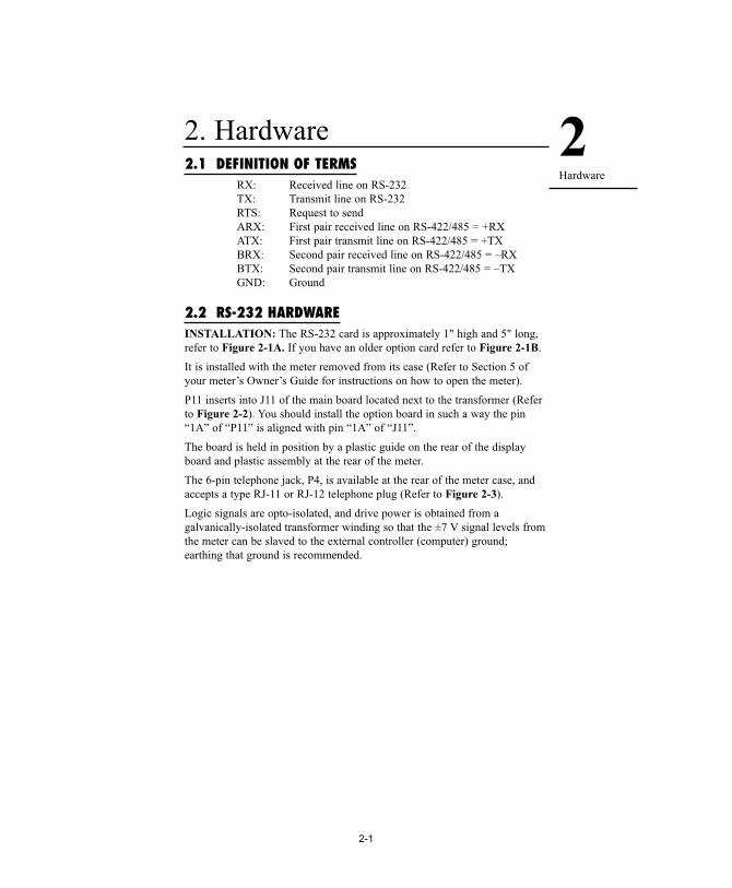
2. Hardware2.1 DEFINITION OF TERMS
RX: Received line on RS-232 TX: Transmit line on RS-232RTS: Request to send ARX: First pair received line on RS-422/485 = +RXATX: First pair transmit line on RS-422/485 = +TXBRX: Second pair received line on RS-422/485 = –RXBTX: Second pair transmit line on RS-422/485 = –TXGND: Ground
2.2 RS-232 HARDWAREINSTALLATION: The RS-232 card is approximately 1" high and 5" long,refer to Figure 2-1A. If you have an older option card refer to Figure 2-1B.
It is installed with the meter removed from its case (Refer to Section 5 ofyour meter’s Owner’s Guide for instructions on how to open the meter).
P11 inserts into J11 of the main board located next to the transformer (Referto Figure 2-2). You should install the option board in such a way the pin“1A” of “P11” is aligned with pin “1A” of “J11”.
The board is held in position by a plastic guide on the rear of the displayboard and plastic assembly at the rear of the meter.
The 6-pin telephone jack, P4, is available at the rear of the meter case, andaccepts a type RJ-11 or RJ-12 telephone plug (Refer to Figure 2-3).
Logic signals are opto-isolated, and drive power is obtained from agalvanically-isolated transformer winding so that the ±7 V signal levels fromthe meter can be slaved to the external controller (computer) ground;earthing that ground is recommended.
2Hardware
2-1

Refer to Figure 2-1A. When interfacing the meter to devices that do nothave handshaking lines, i.e. RTS/CTS, the S3-E Jumper should be installed.However, when interfacing to a PC, the S3-E should be removed.
Figure 2-1A. RS-232 Option Board
Figure 2-1B. Older RS-232 Option Board
Refer to Figure 2-1B. When interfacing the meter to devices that do nothave handshaking lines, i.e. RTS/CTS, the S1-A Jumper should be installed.However, when interfacing to a PC, the S1-A should be removed.
J4
PIN 1
P11
1 N/C2 RTS3 TX4 RX5 COMM RTN6 N/C
RS-232 (P4) AT J4
1
6
PIN 1A
PIN 11S1-A
A B C D E
S1
S1
A B
S3
P11
S3
11
1 1A
J4 1
6
S2
S2A
S4
S4A
METERRJ-12 PIN (J4) RS232
65 GND4 RX3 TX2 RTS1
METERRJ-12 PIN (J4) RS232
65 GND4 RX3 TX2 RTS1
2Hardware
2-2
S1-A installed
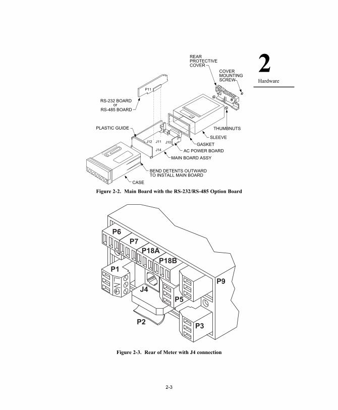
Figure 2-2. Main Board with the RS-232/RS-485 Option Board
Figure 2-3. Rear of Meter with J4 connection
P6P7
P18AP18B
P9
P3
J4
P1
P2
P5
REARPROTECTIVECOVER
COVERMOUNTINGSCREW
THUMBNUTS
RS-232 BOARD
SLEEVE
GASKET
MAIN BOARD ASSY
BEND DETENTS OUTWARDTO INSTALL MAIN BOARD
CASE
P11
J12 J11 J10
J14 AC POWER BOARD
RS-485 BOARDor
PLASTIC GUIDE
2Hardware
2-3

Figures 2-4A and Figure 2-4B show the four-wire RS-232 connectionsbetween the host computer/controller using either a 9-pin or 25-pin “D”connector and the meter (point-to-point full duplex, with RTS handshake).
Figure 2-4A. RJ-11 to D9 Connector
Figure 2-4B. RJ-11 to D25 Connector
Figure 2-4C. RJ-12 to D9 Connector
2 74 3
4 3 2 1
RJ-11D25
3 57 2
4 3 2 1
RJ-11D9
2Hardware
2-4

Table 2.1 shows the pin connection assignments between the RS-232connection on the meter and the 9-pin or 25-pin “D” connectors of yourcomputer.
Table 2.1. Meter Hookup (RS-232) to the ComputerMETER COMPUTER
PIN SIGNAL / (DCE) (DTE)FUNCTION RJ-11 RJ-12 D9 D25RTS, meter from computer 1 2 7 4TX, meter = RX, computer 2 3 2 3RX, meter = TX, computer 3 4 3 2Return 4 5 5 7NC (not connected) 1,6 (all others)
Table 2.2 shows the pin connection assignments between the RS-232connection on the meter and the 9-pin or 25-pin “D” connectors of yourprinter.
Table 2.2. Meter Hookup (RS-232) to the PrinterPIN SIGNAL / METER PRINTERFUNCTION RJ-11 RJ-12 FUNCTIONSRTS, meter 1 2 Data Terminal Ready(DTR)TX, meter 2 3 Received Data (RXD)RX, meter 3 4 Not ConnectedReturn 4 5 Signal ReturnNC (not connected) 1,6
2Hardware
2-5

2.3 RS-485 HARDWAREINSTALLATION: The RS-485 card (refer to Figure 2-5A, or if you havean older option card refer to Figure 2-5B) is the same size and plugs in thesame ways as the RS-232 card, refer to Section 2.2.
Figure 2-5A. RS-485 Option Board
A B C D E
S1
S1
A B
S3
P11
S3
11
1 1A
J4 1
6
S2
S2A
S4
S4A
METER RS485 RS485RJ-12 HALF FULL
PIN (J4) DUPLEX DUPLEX654 RX-3 RX-/TX- TX-2 RX+/TX+ RX+1 TX+
JUMPER RS485 RS485 HALF DUPLEX FULL DUPLEX
S1-A OPEN OPENS1-B CLOSE OPENS2-A CLOSE CLOSES3-A * *
(CLOSE FOR TERMINAL RESISTOR)
S3-B CLOSE OPENS3-C * *
(CLOSE FOR TERMINAL RESISTOR)
S3-D CLOSE OPENS3-E OPEN OPEN
(CLOSE FOR RTS TRUE)
S4(CLOSE FOR * *
CONTINUOUS MODE)Note: * means optional, select as required.
2Hardware
2-6

Figure 2-5B. Older RS-485 Option Board
Figure 2-5B shows the card outline and the pin designators for theconnectors.
There are 4 jumper-selected features.
Putting a jumper in S1-A adjusts for HALF DUPLEX(see Definitions in Section 4)
A jumper in S1-B allows for FULL DUPLEX.
A jumper in S2 adds an impedance-matching 121 ohms across theHALF DUPLEX lines.
A jumper in S3 to impedance-match the other pair of wires, for FULLDUPLEX.
For normal RS-485 operation: remove S4.
For continuous transmission: install S4 and set BUS format menu itemas follows:
BUS.4=0BUS.5=0BUS.7=0
S1A B
S3
A
S2
A
J4
PIN 1
P11
1 TX/RX (A)2 TX/RX (B)3 COMM RTN4 RX (A)5 RX (B)6 N/C
RS-485 (J4)
1
6
S4A
PIN 10
METERRJ-12 PIN (J4) RS485
6 N/C5 RX (B)4 RX (A)3 GND2 TX/RX(B)1 TX/RX(A)
2Hardware
2-7
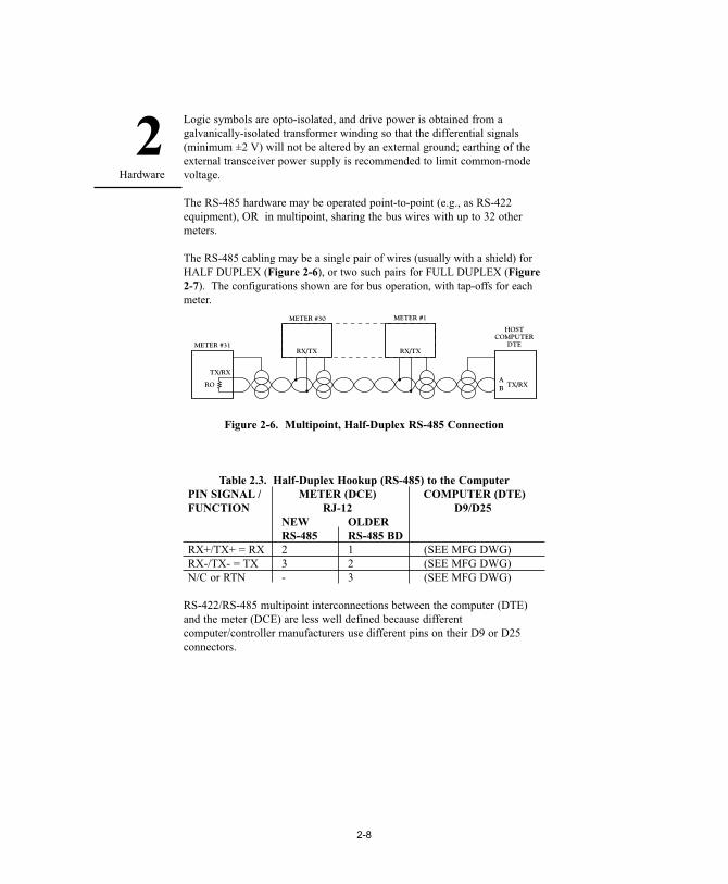
Logic symbols are opto-isolated, and drive power is obtained from agalvanically-isolated transformer winding so that the differential signals(minimum ±2 V) will not be altered by an external ground; earthing of theexternal transceiver power supply is recommended to limit common-modevoltage.
The RS-485 hardware may be operated point-to-point (e.g., as RS-422equipment), OR in multipoint, sharing the bus wires with up to 32 othermeters.
The RS-485 cabling may be a single pair of wires (usually with a shield) forHALF DUPLEX (Figure 2-6), or two such pairs for FULL DUPLEX (Figure2-7). The configurations shown are for bus operation, with tap-offs for eachmeter.
Figure 2-6. Multipoint, Half-Duplex RS-485 Connection
Table 2.3. Half-Duplex Hookup (RS-485) to the ComputerPIN SIGNAL / METER (DCE) COMPUTER (DTE)FUNCTION RJ-12 D9/D25
NEW OLDERRS-485 RS-485 BD
RX+/TX+ = RX 2 1 (SEE MFG DWG)RX-/TX- = TX 3 2 (SEE MFG DWG)N/C or RTN - 3 (SEE MFG DWG)
RS-422/RS-485 multipoint interconnections between the computer (DTE)and the meter (DCE) are less well defined because differentcomputer/controller manufacturers use different pins on their D9 or D25connectors.
METER #30 METER #1
RX/TX RX/TX
TX/RX
ROAB TX/RX
METER #31
HOSTCOMPUTER
DTE
2Hardware
2-8

Figure 2-7. Multipoint Full-Duplex RS-485 Connection
Table 2.4. Full-Duplex Hookup to the Computer
PIN SIGNAL / METER (DCE) COMPUTER (DTE)FUNCTION RJ-12 D9/D25
NEW OLDERRS-485 RS-485 BD
+TX 1 1 (SEE MFG DWG)–TX 3 2 (SEE MFG DWG)+RX 2 4 (SEE MFG DWG)–RX 4 5 (SEE MFG DWG)N/C or RTN - 3 (SEE MFG DWG)N/C - 6
Both HALF DUPLEX (Figure 2-6) and FULL DUPLEX RS-485 (Figure 2-7) communications require a 6-wire RJ-12 plug to be connected to the RJ-12 jack at the rear of the meter.
Unlike RS-232, there presently is no established standard D9 or D25connector pin-out for RS-485; refer to your computer or controller manual toinsure the right cable connections.
METER #30 METER #1
RECEIVE
RX/TX
ROA
BTRANSMIT
METER #31
HOSTCOMPUTER
DTE
RO
TRANSMITA
BRECEIVE
= TWISTED SHIELDED PAIR
NOTE: If communications with your meter has failed, it is recommendedthat you check for the receive portion of the RS-485 board on DTE(computer). These lines should be pulled up for +RX and pulled down for–RX with resistors with a resistance value from 330 ohms to 1K ohms.
2Hardware
2-9

NOTES2Hardware
2-10

3-1
Free software for NEWPORT devices featuring Ethernet or Serial Communicationsis on the CD-ROM enclosed with this shipment.
To download the latest software release (or request a free CD-ROM) please go to:www.newportUS.com/software

3-2

4-1

4-2

4-3

4-4
4-5

4-6

4-7

4-8

5-1

5-2

6-1

6-2

7-1

7-2

7-3

7-4

7-5

7-6

8-1

8-2
8-3

8-4

8-5

8-6

8-7

8-8

8-9

8-10

8-11

8-12

8-13

8-14

8-15

8-16

8-17

8-18

8-19

8-20

8-21

8-22

8-23

8-24

8-25

8-26

9-1

9-2

9-3

9-4

9-5

9-6

9-7

9-8

10-1

10-2

10-3

10-4

10-5

10-6

10-7

10-8
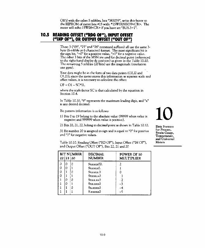
10-9

10-10

10-11
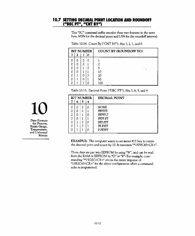
10-12

10-13

10-14

10-15

10-16

10-17

10-18

10-19

10-20

10-21
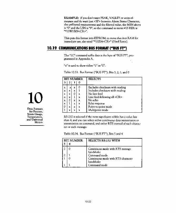
10-22

10-23

10-24

10-25

10-26

10-27

10-28

10-29

10-30

11-1

11-2

11-3

11-4

11-5

11-6

11-7

11-8

11-9

11-10

11-11

11-12

11-13

11-14

11-15

11-16

11-17

11-18

11-19

11-20
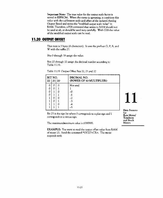
11-21

11-22

11-23

11-24

11-25

11-26
11-27

11-28

11-29
11-30
11-31

11-32

11-33

11-34

11-35

11-36

I-1
I-2

I-3

I-4

I-5

I-6

I-7

I-8

I-9


FOR WARRANTY RETURNS, please have the following information available BEFORE contactingOMEGA:1. P.O. number under which the product was
PURCHASED,2. Model and serial number of the product under
warranty, and3. Repair instructions and/or specific problems
relative to the product.
FOR NON-WARRANTY REPAIRS, consult OMEGA forcurrent repair charges. Have the followinginformation available BEFORE contacting OMEGA:1. P.O. number to cover the COST of the repair,2. Model and serial number of product,
and3. Repair instructions and/or specific problems
relative to the product.
WARRANTY/DISCLAIMEROMEGA ENGINEERING, INC. warrants this unit to be free of defects in materials and workmanship for a period of one(1) year from the date of purchase. In addition to OMEGA’s standard warranty period, OMEGA Engineering will extendthe warranty period for four (4) additional years if the warranty card enclosed with each instrument is returned toOMEGA.If the unit should malfunction, it must be returned to the factory for evaluation. OMEGA’s Customer Service Department willissue an Authorized Return (AR) number immediately upon phone or written request. Upon examination by OMEGA, if theunit is found to be defective it will be repaired or replaced at no charge. OMEGA’s WARRANTY does not apply to defectsresulting from any action of the purchaser, including but not limited to mishandling, improper interfacing, operation outsideof design limits, improper repair, or unauthorized modification. This WARRANTY is VOID if the unit shows evidenceof having been tampered with or shows evidence of being damaged as a result of excessive corrosion; orcurrent, heat, moisture or vibration; improper specification; misapplication; misuse or other operatingconditions outside of OMEGA’s control. Components which wear are not warranted, including but not limited to contact points, fuses, and triacs.O M E G A i s p l e a s e d t o o f f e r s u g g e s t i o n s o n t h e u s e o f i t s v a r i o u s p r o d u c t s . H o w e v e r, OMEGA neither assumes responsibility for any omissions or errors nor assumes liability forany damages that result from the use of its products in accordance with information providedby OMEGA, either verbal or written. OMEGA warrants only that the parts manufactured by itw i l l b e a s s p e c i f i e d a n d f r e e o f d e f e c t s . O M E G A M A K E S N O O T H E R WA R R A N T I E S O R REPRESENTATIONS OF ANY KIND WHATSOEVER, EXPRESSED OR IMPLIED, EXCEPT THAT OFTITLE, AND ALL IMPLIED WARRANTIES INCLUDING ANY WARRANTY OF MERCHANTABILITYAND F ITNESS FOR A PARTICULAR PURPOSE ARE HEREBY DISCLAIMED. L IMITATION OF LIABILITY: The remedies of purchaser set forth herein are exclusive and the total liability of O M E G A w i t h r e s p e c t t o t h i s o r d e r, w h e t h e r b a s e d o n c o n t r a c t , w a r r a n t y, n e g l i g e n c e , indemni f icat ion , s t r ic t l iab i l i ty or o therwise , sha l l not exceed the purchase pr ice of the c o m p o n e n t u p o n w h i c h l i a b i l i t y i s b a s e d . I n n o e v e n t s h a l l O M E G A b e l i a b l e f o r consequential, incidental or special damages.CONDITIONS: Equipment sold by OMEGA is not intended to be used, nor shall it be used: (1) as a “Basic Component”under 10 CFR 21 (NRC), used in or with any nuclear installation or activity; or (2) in medical applications or used onhumans. Should any Product(s) be used in or with any nuclear installation or activity, medical application, used on humans,or misused in any way, OMEGA assumes no responsibility as set forth in our basic WARRANTY/DISCLAIMER language,and additionally, purchaser will indemnify OMEGA and hold OMEGA harmless from any liability or damage whatsoeverarising out of the use of the Product(s) in such a manner.
RETURN REQUESTS / INQUIRIESDirect all warranty and repair requests/inquiries to the OMEGA Customer Service Department. BEFORE RETURNINGANY PRODUCT(S) TO OMEGA, PURCHASER MUST OBTAIN AN AUTHORIZED RETURN (AR) NUMBER FROMOMEGA’S CUSTOMER SERVICE DEPARTMENT (IN ORDER TO AVOID PROCESSING DELAYS). The assigned ARnumber should then be marked on the outside of the return package and on any correspondence.The purchaser is responsible for shipping charges, freight, insurance and proper packaging to prevent breakage intransit.
OMEGA’s policy is to make running changes, not model changes, whenever an improvement is possible. This affords our customers thelatest in technology and engineering.
OMEGA is a registered trademark of OMEGA ENGINEERING, INC.
© Copyright 2007 OMEGA ENGINEERING, INC. All rights reserved. This document may not be copied, photocopied, reproduced,translated, or reduced to any electronic medium or machine-readable form, in whole or in part, without prior written consent of OMEGAENGINEERING, INC.
PATENT NOTICE: The “Meter Case Bezel Design” is a trademark of NEWPORT Electronics, Inc., registered in the U.S. USED UNDERLICENSE. PATENT NOTICE: This product is covered by one or more of the following patents: U.S. Pat. No. Des. 336,895; 5,274,577 /Canada 2052599; 2052600 / Italy 1249456; 1250938 / France Brevet No. 91 12756 / Spain 2039150; 2048066 / UK Patent No. GB2 249 837; GB2 248 954 / Germany DE 41 34398 C2. Other International Patents Pending.

M1519/0907 11594ML-99 Rev. L
Where Do I Find Everything I Need for Process Measurement and Control?
OMEGA…Of Course!Shop on line at omega.com
TEMPERATURE�� Thermocouple, RTD & Thermistor Probes, Connectors, Panels & Assemblies�� Wire: Thermocouple, RTD & Thermistor�� Calibrators & Ice Point References�� Recorders, Controllers & Process Monitors�� Infrared Pyrometers
PRESSURE, STRAIN AND FORCE�� Transducers & Strain Gauges�� Load Cells & Pressure Gauges�� Displacement Transducers�� Instrumentation & Accessories
FLOW/LEVEL�� Rotameters, Gas Mass Flowmeters & Flow Computers�� Air Velocity Indicators�� Turbine/Paddlewheel Systems�� Totalizers & Batch Controllers
pH/CONDUCTIVITY�� pH Electrodes, Testers & Accessories�� Benchtop/Laboratory Meters�� Controllers, Calibrators, Simulators & Pumps�� Industrial pH & Conductivity Equipment
DATA ACQUISITION�� Data Acquisition & Engineering Software�� Communications-Based Acquisition Systems�� Plug-in Cards for Apple, IBM & Compatibles�� Datalogging Systems�� Recorders, Printers & Plotters
HEATERS�� Heating Cable�� Cartridge & Strip Heaters�� Immersion & Band Heaters�� Flexible Heaters�� Laboratory Heaters
ENVIRONMENTALMONITORING AND CONTROL�� Metering & Control Instrumentation�� Refractometers�� Pumps & Tubing�� Air, Soil & Water Monitors�� Industrial Water & Wastewater Treatment�� pH, Conductivity & Dissolved Oxygen Instruments