Embed Size (px)
Citation preview
DP14 - DP14A
Product / Produit:
Serial number / Numéro de série:

DP14 [LIVRET].doc 09/2008
IMPORTANT SAFETY INSTRUCTIONSSAVE THESE INSTRUCTIONS
DANGER
TO REDUCE THE RISK OF FIRE OR ELECTRIC SHOCKCAREFULLY FOLLOW THESE INSTRUCTIONS
TABLE OF CONTENTS(table des matières :page suivante)
Description ___________________________________________________________________ A-1Introduction________________________________________________________________ A-2Construction _______________________________________________________________ A-2Shipping __________________________________________________________________ A-2Installation warnings_________________________________________________________ A-4Distances to respect__________________________________________________________ A-4Installation ________________________________________________________________ A-6Operation _________________________________________________________________ A-8Troubleshooting ___________________________________________________________ A-10Oven maintenance and cleaning _______________________________________________ A-12
Component parts ________________________________________________________________B-1DP14 - Front view ____________________________________________________________B-2DP14 - Top view _____________________________________________________________B-4DP14A - Front view___________________________________________________________B-6DP14A - Top view____________________________________________________________B-8
Control Panels__________________________________________________________________C-1DP14 1PH 120V 60HZ ________________________________________________________C-2DP14 1PH 120V/208V 120V/240V 60HZ__________________________________________C-3DP14 1PH 208-220-240V 50/60HZ_______________________________________________C-4DP14 1PH 120V 60HZ AUTO __________________________________________________C-5DP14 1PH 120V/208V 120V/240V 60HZ AUTO____________________________________C-6DP14 1PH 208-220-240V 50/60HZ AUTO_________________________________________C-7
Warranty ________________________________________________________________________1
DP14 [LIVRET].doc 09/2008
IMPORTANT INSTRUCTIONS DE SÉCURITÉCONSERVEZ CE MANUEL D�INSTRUCTIONS
DANGER
AFIN DE RÉDUIRE LES RISQUES D'INCENDIE OU D'ÉLECTROCUTIONSUIVRE CES INSTRUCTIONS AVEC SOIN
TABLE DES MATIÈRES
Description ____________________________________________________________________A-1Introduction ________________________________________________________________A-3Construction ________________________________________________________________A-3Expédition __________________________________________________________________A-3Avertissement lors de l'installation_______________________________________________A-5Distances à respecter _________________________________________________________A-5Installation _________________________________________________________________A-7Opération __________________________________________________________________A-9Dépannage ________________________________________________________________A-11Entretien et nettoyage du four__________________________________________________A-13
Pièces composantes _____________________________________________________________B-1DP14 - Vue de face ___________________________________________________________B-2DP14 - Vue de dessus _________________________________________________________B-4DP14A - Vue de face __________________________________________________________B-6DP14A - Vue de dessus ________________________________________________________B-8
Panneaux de contrôle ____________________________________________________________C-1DP14 1PH 120V 60HZ ________________________________________________________C-2DP14 1PH 120V/208V 120V/240V 60HZ __________________________________________C-3DP14 1PH 208-220-240V 50/60HZ_______________________________________________C-4DP14 1PH 120V 60HZ AUTO___________________________________________________C-5DP14 1PH 120V/208V 120V/240V 60HZ AUTO _____________________________________C-6DP14 1PH 208-220-240V 50/60HZ AUTO _________________________________________C-7
Garantie ________________________________________________________________________1

SECTION A: DESCRIPTION / DESCRIPTION
A-2
CAUTION
The manufacturer suggests to read this manual carefully.
INTRODUCTION
This equipment is manufactured with first quality material by experienced technicians. Properinstallation and maintenance will guarantee a reliable service for years to come.
A nameplate fixed to the front of the proofer specifies the serial number, model number, number ofphase, amperage, voltage and frequency.
Drawings and replacement part numbers are included in this manual. The electrical diagram is affixedin the control panel located on the top of the proofer.
ATTENTION
DOYON is not responsible for damages to the property or the equipment causedby personnel who is not certified by known organisations. The customer isresponsible for finding qualified technicians in electricity and plumbing for theinstallation of the oven.
CONSTRUCTION
You just bought the most advanced proofer in the world, the "DOYON" technology at its best. Thisproofer is manufactured using the highest quality components and material.
The DOYON equipments are designed with parts that are easy to find.
SHIPPING
For your safety, this equipment has been verified by qualified technicians and carefully crated beforeshipment. The freight company assumes full responsibility concerning the delivery in good condition ofthe equipment in accepting to transport it.
IMPORTANT
RECEPTION OF THE MERCHANDISE
Take care to verify that the received equipment is not damaged before signing the delivery receipt. If adamage or a lost part is noticed, write it clearly on the receipt. If it is noticed after the carrier has left,contact immediately the freight company in order that they do their inspection.
We do not assume the responsibility for damages or losses that may occur during transportation.
A-3
ATTENTIONLe manufacturier suggère de lire ce manuel attentivement et de suivre avec soin les instructionsfournies.
INTRODUCTION
Votre équipement est fabriqué avec des matériaux de première qualité par des techniciensd'expérience. Une utilisation normale et un entretien adéquat de l'équipement vous assurerontplusieurs années de bon service.
Une plaque signalétique, située à l�avant de l�étuve, mentionne le numéro de série, le numéro dumodèle, le nombre de phases, l�ampérage, le voltage et la fréquence.
Les dessins et les numéros de pièces de rechange sont inclus dans ce manuel. Le plan électrique estaffiché dans la boîte de contrôle sur le dessus de l�étuve.
ATTENTION
Équipement Doyon Inc. ne peut être tenu responsable pour les dommages causés àla propriété ou à l'équipement par du personnel non certifié par des organismesaccrédités. Le client a la responsabilité de retenir les services d'un technicienspécialisé en électricité et d'un plombier qualifié pour l'installation de l'étuve.
CONSTRUCTION
Vous avez maintenant en votre possession l�étuve la plus performante présentement disponible sur lemarché, une étuve utilisant la technologie "Doyon" à son meilleur. Cette étuve est fabriquée avec desmatériaux de première qualité.
L�étuve DOYON est fabriquée avec des matériaux et pièces composantes facilement disponibles sur lemarché.
EXPÉDITION
Pour votre protection, cet équipement a été vérifié et emballé avec précaution par des techniciensqualifiés avant son expédition. La compagnie de transport assume la pleine responsabilitéconcernant la livraison de cet équipement en bon état en acceptant de le transporter.
IMPORTANT
RÉCEPTION DE LA MARCHANDISE
Avant de signer le reçu de livraison, prenez soin de vérifier dès la réception si l'équipement n'est pasendommagé. Si un dommage ou une perte est détecté, écrivez-le clairement sur le reçu de livraisonou votre bon de transport et faites signer le livreur. Si le dommage est remarqué après le départ dutransporteur, contactez immédiatement la compagnie de transport afin de leur permettre deconstater les dommages causés.
Nous ne pouvons assumer la responsabilité pour les dommages ou les pertes qui pourraient survenirpendant le transport.
A-4
INSTALLATION WARNINGS
FOR YOUR SAFETY
DO NOT STORE OR USE GASOLINE OR OTHER FLAMMABLE VAPORSAND LIQUIDS IN THE VICINITY OF THIS OR ANY APPLIANCE.
IMPORTANT
INSTALLATION AND SERVICE
Installation and service must be done by specialized technicians. Contact a certified electrician andplumber for set up.
The proofer must be connected to the utility and electrically grounded in conformity to the effectivelocal regulations. If these are not established, the oven must be connected according to the CanadianElectrical Code (CSA-C22.1-XX) or National Electrical Code (NFPA 70-XX). Refer to last editionyear for XX.
DISTANCES TO RESPECT
● Top of the proofer: a clearance of 12 inches to the ceiling must exist to permit maintenance.
● Back and sides:0 inch clearance.
A-5
AVERTISSEMENT LORS DE L'INSTALLATION
POUR VOTRE SÉCURITÉ
NE PAS EMMAGASINER OU UTILISER D'ESSENCE OU AUTRES VAPEURSET LIQUIDES INFLAMMABLES À PROXIMITÉ DE CET ÉQUIPEMENT
OU DE TOUT AUTRE APPAREIL.
IMPORTANT
INSTALLATION ET SERVICE
L'installation et le service doivent être faits par un technicien spécialisé. Contactez un technicienspécialisé en électricité pour l'installation d�une prise de courant adéquate.
Cet appareil doit être branché et mis à la terre (grounded) conformément aux règlements effectifs devotre localité. Si aucune réglementation n'est établie, l�appareil doit être branché conformément auCode Canadien de l�électricité CSA 22.1-XX ou au Code National de l'Électricité NFPA 70-XX.Référez vous à l�année de la dernière édition pour XX.
DISTANCES À RESPECTER
● Dessus de l'étuve : Il est obligatoire d�avoir au moins 12 pouces entre le dessus de l�étuve et leplafond afin d�effectuer le service.
● Arrière et côtés de l'étuve :Aucun espace nécessaire.
A-6
INSTALLATION
IN GENERAL
Take off the packaging material with care. Take off all the material used for packing andaccessories.
Each unit is set up to be used with the electrical supply specified on the nameplate fixed on the frontof the unit.
If the equipment is delivered with casters , always LOCK the wheels after installation and use aflexible wire.
1. To the electrician
Electrical supply installation must be in accordance with the electrical rating on the nameplate anduse flexible wire.
2. To the plumber
MANUAL WATER FILLNo water line is required. Water is filled manually in the pan inside the proofer.
This equipment is to be installed to comply with the applicable federal, state or local plumbingcodes.
Connect the steam system (1/4 NPT) to the cold water distribution network.We highly recommend a water softener to eliminate minerals in the water.We suggest to use CUNO # CFS6135 (Doyon part number PLF240).
A-7
INSTALLATION
EN GÉNÉRAL
Ouvrir avec soin l'emballage de votre équipement. Enlever tous les matériaux utilisés pourl'envelopper ainsi que les accessoires.
Chaque unité est fabriquée pour être utilisée avec la source électrique spécifiés sur la plaquesignalétique de l�appareil.
Si l�appareil est muni de roulettes,veuillez toujours les BLOQUER après l�installation et utiliser uncordon souple.
1. À l'électricien
L�installation de l�alimentation électrique des fours doit être conforme avec la source électriquespécifiée sur la plaque signalétique et vous devez utiliser un conduit flexible approprié.
2. Au plombier
REMPLISSAGE MANUEL DU RÉSERVOIR D'EAUAucune ligne d�eau n�est requise. Le réservoir d�eau à l�intérieur de l�étuve est remplimanuellement.
Relier le système de vapeur (1/4 NPT) au réseau de distribution d�eau.Il est fortement recommandé d�installer un adoucisseur d�eau à l�entrée de l�appareil afind�éliminer les minéraux dans l�eau.Nous recommandons la marque CUNO #CFS6135 (numéro de pièce Doyon PLF240).

A-8
OPERATION
1. Switch "ON".
2. Set the thermostat control at 100° F.
3. Fill water pan if not automatic and set the humidity control at 4.
If there is too much fog and water drips from the glass doors, adjust humidity control to a lowernumber.
4. When the temperature is stabilized, put the products in the proofer.(Leave them inside until they are ready to bake.)
5. When proofing cycle is completed, turn the switch "OFF".
When the proofer is not in operation, open the doors to let out the humidity and to preventmould.
P.S. The doors should not be opened unnecessarily to conserve the heat and humidity in theproofer.
Every day cleaning of the water pan under the proofer's doors should be exercised.
POWER FAILURE
When the power comes back, the proofer will start automatically. Then it is recommended to turnoff the unit to avoid it starting without supervision.

A-9
OPÉRATION
1. Placer l'interrupteur à "ON".
2. Placer le bouton du thermostat à 100°F.
3. Remplir le réservoir d�eau si ce n�est pas automatique et régler le contrôle d�humidité à 4.S�il y a trop de vapeur, l�eau condensera sur la vitre et des gouttelettes glisseront. Il faut alorsdiminuer le réglage d�humidité.
4. Quand la température est stabilisée, charger l�étuve.(Laisser le produit à l�intérieur jusqu�à ce qu�il soit prêt à cuire.)
5. Lorsque le cycle d�étuvage est complété, placer l�interrupteur à "OFF".
Lorsque l�étuve ne fonctionne pas, ouvrir les portes pour laisser sortir l�humidité afin de prévenirla formation de moisissure.
N.B. Bien fermer les portes et ne pas les ouvrir inutilement pour conserver la chaleur et la vapeurdans l'étuve.
Bien nettoyer à tous les jours le récupérateur d'eau situé en dessous de la porte.
PANNE DE COURANT
Au retour du courant, l�étuve se remet en marche automatiquement. Il est donc nécessaire de mettrele sélecteur à "ARRËT" afin d�éviter que l�étuve ne redémarre sans surveillance.
A-10
TROUBLESHOOTING
BEFORE CALLING FOR SERVICEANSWERS TO MOST FREQUENT QUESTIONS
Always cut off the main power before replacing any parts. Take care of water piping andelectric cable.
Control parts on the front: To remove parts from front panels, you have togo on the top of the unit.
Control panel, proofer unit and refrigerationunit:
They are located on the top.
Questions Solutions
The unit does not turn on when installed. Check if the light is on.Check if the proofer switch is on.Check the breaker of the building.Check the fuses on the front and in the electricalcontrol panel.
The blower runs but the unit does not produceheat.
Make sure that the thermostat is adjusted to thedesired temperature (over ambient temperature)and the pilot light is lit.
The blower runs but the unit does not producesteam.
Make sure that the humidity control is set atabout 4.Check if you have water in the pan and if the panis sit properly on the element.
A-11
DÉPANNAGE
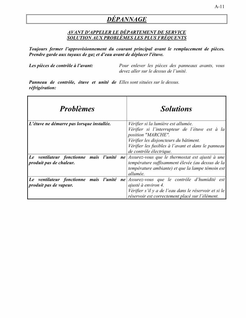
AVANT D'APPELER LE DÉPARTEMENT DE SERVICESOLUTION AUX PROBLÈMES LES PLUS FRÉQUENTS
Toujours fermer l�approvisionnement du courant principal avant le remplacement de pièces.Prendre garde aux tuyaux de gaz et d�eau avant de déplacer l'étuve.
Les pièces de contrôle à l�avant: Pour enlever les pièces des panneaux avants, vousdevez aller sur le dessus de l�unité.
Panneau de contrôle, étuve et unité deréfrigération:
Elles sont situées sur le dessus.
Problèmes Solutions
L�étuve ne démarre pas lorsque installée. Vérifier si la lumière est allumée.Vérifier si l�interrupteur de l�étuve est à laposition "MARCHE".Vérifier les disjoncteurs du bâtiment.Vérifier les fusibles à l�avant et dans le panneaude contrôle électrique.
Le ventilateur fonctionne mais l�unité neproduit pas de chaleur.
Assurez-vous que le thermostat est ajusté à unetempérature suffisamment élevée (au dessus de latempérature ambiante) et que la lampe témoin estallumée.
Le ventilateur fonctionne mais l�unité neproduit pas de vapeur.
Assurez-vous que le contrôle d�humidité estajusté à environ 4.Vérifier s�il y a de l�eau dans le réservoir et si leréservoir est correctement placé sur l�élément.
A-12
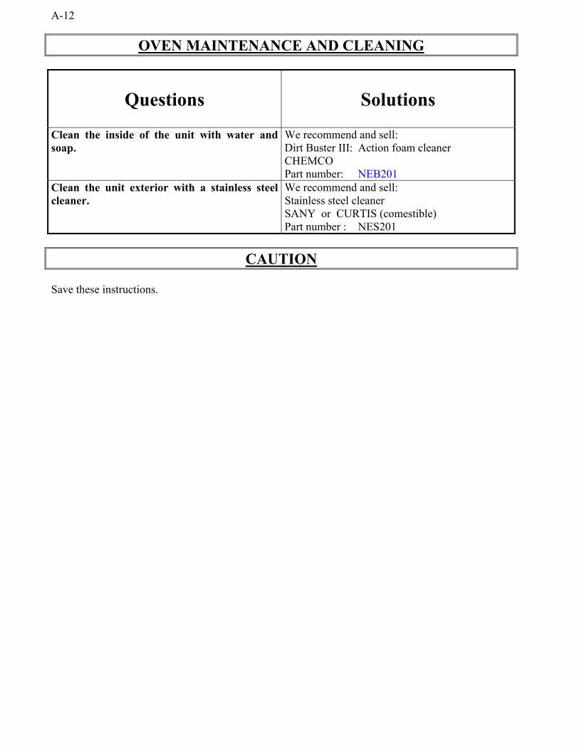
OVEN MAINTENANCE AND CLEANING
Questions Solutions
Clean the inside of the unit with water andsoap.
We recommend and sell:Dirt Buster III: Action foam cleanerCHEMCOPart number: NEB201
Clean the unit exterior with a stainless steelcleaner.
We recommend and sell:Stainless steel cleanerSANY or CURTIS (comestible)Part number : NES201
CAUTION
Save these instructions.
A-13
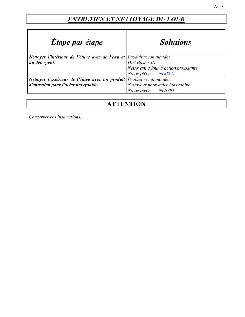
ENTRETIEN ET NETTOYAGE DU FOUR
Étape par étape Solutions
Nettoyer l'intérieur de l'étuve avec de l'eau etun détergent.
Produit recommandé:Dirt Buster IIINettoyant à four à action moussanteNo de pièce: NEB201
Nettoyer l'extérieur de l'étuve avec un produitd'entretien pour l'acier inoxydable.
Produit recommandé:Nettoyeur pour acier inoxydableNo de pièce: NES201
ATTENTION
Conserver ces instructions.


SECTION B: COMPONENT PARTS / PIÈCES COMPOSANTES

B-2DP14 - FRONT VIEWDP14 - VUE DE FACE
G:\ACAD10\ETUVE\MANUEL\DP14 FACE.dft
DP14VUE DE FACE/FRONT VIEW
1
14
15
2
6
43
7
16
17
13
10 12
5
20
21
18 19
9 118
B-2

B-3
Item Part Number Description Quantity1 P1555EG LEFT DOOR DP14 (55 3/16" X 15 7/16") 12 QUP320 DOOR HINGE 43 ELT628 THERMOSTAT KNOB 110°F 14 ELT620 THERMOSTAT BEZEL 15 ELT627 THERMOSTAT 110°F 16 ELL650 RED PILOT LIGHT 250V 27 ELI240 INFINITY SWITCH KNOB 18 ELI220 HUMIDITY CONTROL 120V 19 ELI230 HUMIDITY CONTROL 240V 110 ELI402 BLACK SELECTOR 2 POS. 111 ELI406 BASE WITH 1NO 112 ELB098 2A BREAKER 113 QUA200 DOOR MAGNET 414 P1555ED RIGHT DOOR DP14 (55 3/16" X 15 7/16") 115 QUP465 STAIN. STEEL TUBULAR HANDLE FOR DOOR 216 ETUVE_0924 14 SHELVES SIDERACK 217 REEF10 WATER PAN FOR PROOFER 13 X 14 X 2 1/2 118 ELE127F01 FORMED ELEMENT FOR DP14 (MANUAL) 120V 1250 W 119 ELE124F03 FORMED ELEMENT 240V 1250 W FOR DP14 (MANUAL) 120 PAR850 SWIVEL CASTER WITH BRAKE 221 PAR800 SWIVEL CASTER 1
Item Numéro Pièce Description Quantité1 P1555EG PORTE GAUCHE DP14 (55 3/16" X 15 7/16") 12 QUP320 PENTURE DE PORTE 43 ELT628 BOUTON DE THERMOSTAT 110°F 14 ELT620 PLAQUE DE THERMOSTAT 15 ELT627 THERMOSTAT 110°F 16 ELL650 LAMPE TEMOIN ROUGE 250 V 27 ELI240 BOUTON DE CONTRÔLE D'HUMIDITÉ 18 ELI220 CONTRÔLEUR D'HUMIDITÉ 120V 19 ELI230 CONTRÔLEUR D'HUMIDITÉ 240V 110 ELI402 SÉLECTEUR 2 POS. NOIR 111 ELI406 BASE AVEC 1NO 112 ELB098 DISJONCTEUR 2A 113 QUA200 AIMANT DE PORTE 414 P1555ED PORTE DROITE DP14 (55 3/16" X 15 7/16") 115 QUP465 POIGNÉE DE PORTE TUBULAIRE (ACIER INOX.) 216 ETUVE_0924 SUPPORT LATÉRAL 14 TABLETTES 217 REEF10 PLAT D'EAU POUR ÉTUVE 13 X 14 X 2 1/2 118 ELE127F01 ÉLÉMENT FORMÉ 120V 1250 W POUR DP14 (MANUEL) 119 ELE124F03 ÉLÉMENT FORMÉ 240V 1250 W POUR DP14 (MANUEL) 120 PAR850 ROULETTE PIVOTANTE AVEC FREIN 221 PAR800 ROULETTE PIVOTANTE 1
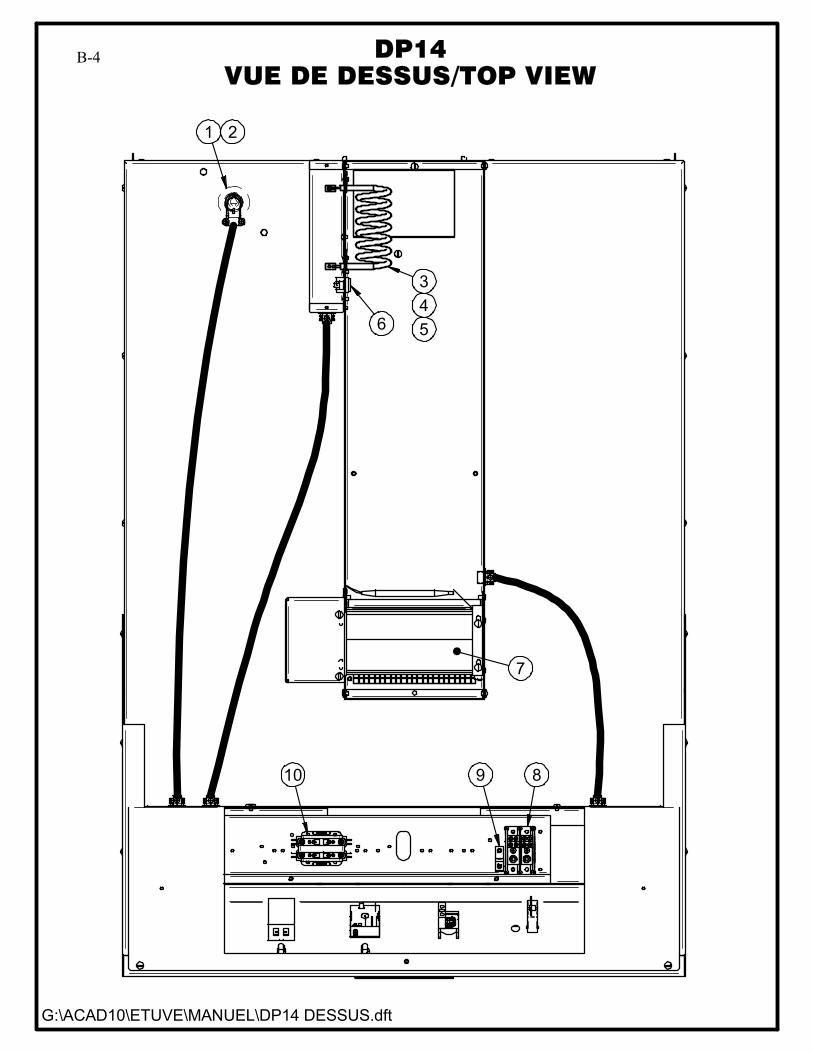
B-4DP14 - TOP VIEW
DP14 - VUE DE DESSUS
G:\ACAD10\ETUVE\MANUEL\DP14 DESSUS.dft
DP14VUE DE DESSUS/TOP VIEW
6
7
10 9 8
345
1 2
B-4
B-5
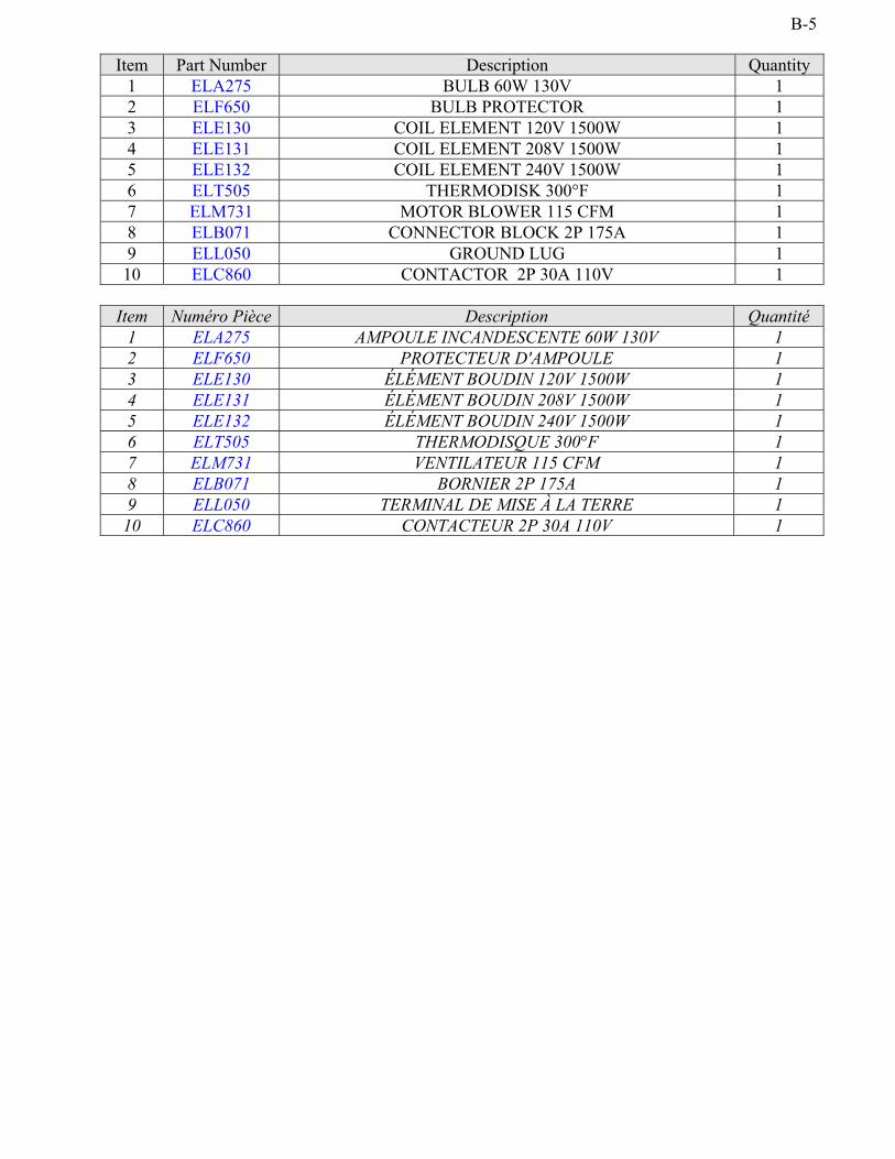
Item Part Number Description Quantity1 ELA275 BULB 60W 130V 12 ELF650 BULB PROTECTOR 13 ELE130 COIL ELEMENT 120V 1500W 14 ELE131 COIL ELEMENT 208V 1500W 15 ELE132 COIL ELEMENT 240V 1500W 16 ELT505 THERMODISK 300°F 17 ELM731 MOTOR BLOWER 115 CFM 18 ELB071 CONNECTOR BLOCK 2P 175A 19 ELL050 GROUND LUG 110 ELC860 CONTACTOR 2P 30A 110V 1
Item Numéro Pièce Description Quantité1 ELA275 AMPOULE INCANDESCENTE 60W 130V 12 ELF650 PROTECTEUR D'AMPOULE 13 ELE130 ÉLÉMENT BOUDIN 120V 1500W 14 ELE131 ÉLÉMENT BOUDIN 208V 1500W 15 ELE132 ÉLÉMENT BOUDIN 240V 1500W 16 ELT505 THERMODISQUE 300°F 17 ELM731 VENTILATEUR 115 CFM 18 ELB071 BORNIER 2P 175A 19 ELL050 TERMINAL DE MISE À LA TERRE 110 ELC860 CONTACTEUR 2P 30A 110V 1
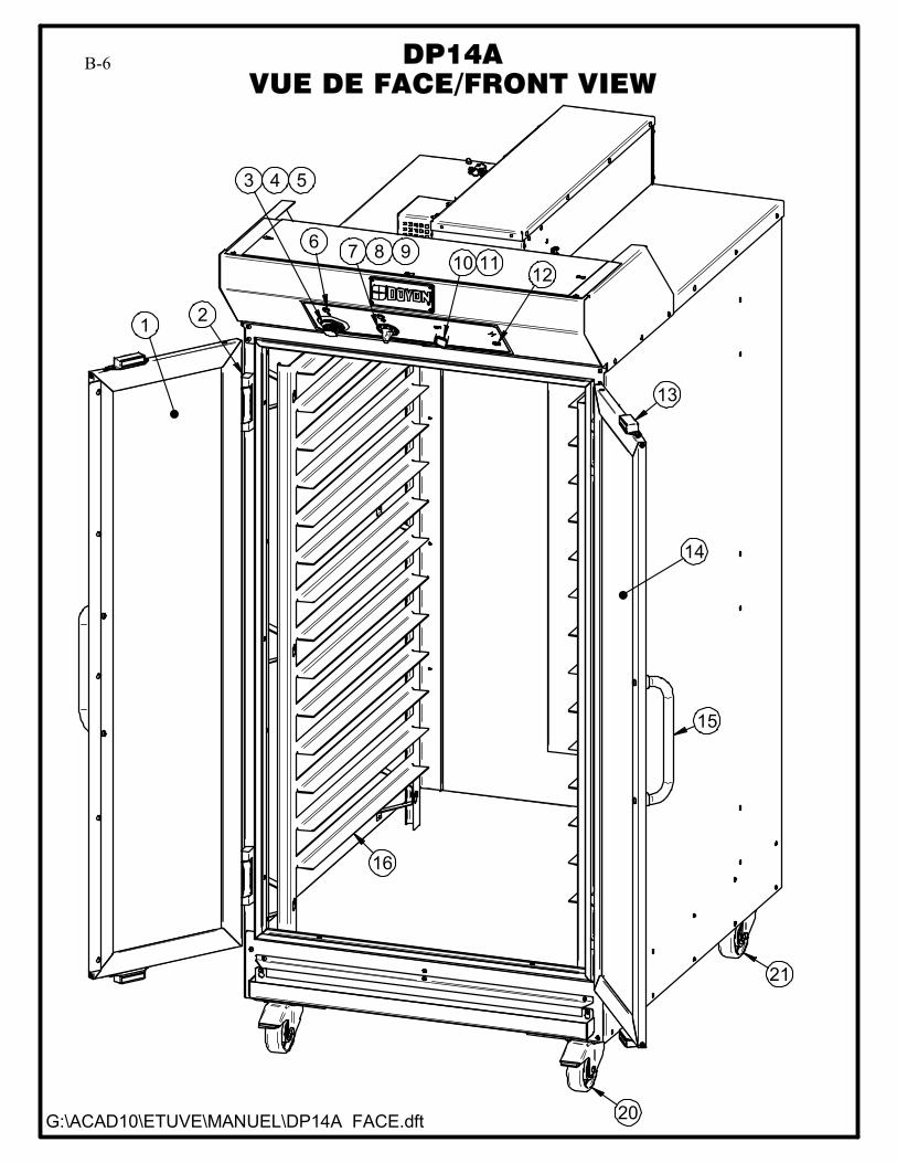
B-6DP14A - FRONT VIEWDP14A - VUE DE FACE
G:\ACAD10\ETUVE\MANUEL\DP14A FACE.dft
DP14AVUE DE FACE/FRONT VIEW
1
14
15
2
6
43
7
16
13
10 12
5
20
21
9 118
B-6

B-7
Item Part Number Description Quantity1 P1555EG LEFT DOOR DP14 (55 3/16" X 15 7/16") 12 QUP320 DOOR HINGE 43 ELT628 THERMOSTAT KNOB 110°F 14 ELT620 THERMOSTAT BEZEL 15 ELT627 THERMOSTAT 110°F 16 ELL650 RED PILOT LIGHT 250V 27 ELI240 INFINITY SWITCH KNOB 18 ELI220 HUMIDITY CONTROL 120V 19 ELI230 HUMIDITY CONTROL 240V 110 ELI402 BLACK SELECTOR 2 POS. 111 ELI406 BASE WITH 1NO 112 ELB098 2A BREAKER 113 QUA200 DOOR MAGNET 414 P1555ED RIGHT DOOR DP14 (55 3/16" X 15 7/16") 115 QUP465 STAIN. STEEL TUBULAR HANDLE FOR DOOR 216 ETUVE_0924 14 SHELVES SIDERACK 220 PAR850 SWIVEL CASTER WITH BRAKE 221 PAR800 SWIVEL CASTER 2
Item Numéro Pièce Description Quantité1 P1555EG PORTE GAUCHE DP14 (55 3/16" X 15 7/16") 12 QUP320 PENTURE DE PORTE 43 ELT628 BOUTON DE THERMOSTAT 110°F 14 ELT620 PLAQUE DE THERMOSTAT 15 ELT627 THERMOSTAT 110°F 16 ELL650 LAMPE TEMOIN ROUGE 250 V 27 ELI240 BOUTON DE CONTRÔLE D'HUMIDITÉ 18 ELI220 CONTRÔLEUR D'HUMIDITÉ 120V 19 ELI230 CONTRÔLEUR D'HUMIDITÉ 240V 110 ELI402 SÉLECTEUR 2 POS. NOIR 111 ELI406 BASE AVEC 1NO 112 ELB098 DISJONCTEUR 2A 113 QUA200 AIMANT DE PORTE 414 P1555ED PORTE DROITE DP14 (55 3/16" X 15 7/16") 115 QUP465 POIGNÉE DE PORTE TUBULAIRE (ACIER INOX.) 216 ETUVE_0924 SUPPORT LATÉRAL 14 TABLETTES 220 PAR850 ROULETTE PIVOTANTE AVEC FREIN 221 PAR800 ROULETTE PIVOTANTE 2
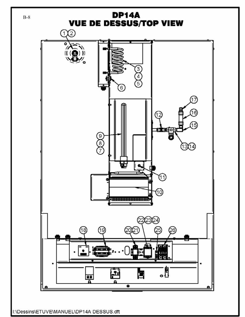
B-8DP14A - TOP VIEW
DP14A - VUE DE DESSUSB-8
B-9Item Part Number Description Quantity
1 ELA275 BULB 60W 130V 12 ELF650 BULB PROTECTOR 13 ELE130 COIL ELEMENT 120V 1500W 14 ELE131 COIL ELEMENT 208V 1500W 15 ELE132 COIL ELEMENT 240V 1500W 16 ELT505 THERMODISK 300°F 17 ELE165 IMMERSION ELEMENT 120V 1500W 18 ELE166 IMMERSION ELEMENT 208V 1500W 19 ELE167 IMMERSION ELEMENT 240V 1500W 1
10 ELM731 MOTOR BLOWER 115 CFM 111 QUF350 ELECTRIC FLOAT 112 ELV590 NEEDLE VALVE 113 ELS887 SOLENOID VALVE WITH DIN CONNECTION 110/120V 50/60HZ 114 ELS889 JONCTION BOX FOR ELS887 & ELS888 115 PLCU36 COPPER ELBOW 1/4 FEM/FEM 116 PLF100 WATER FILTER 117 PLCU90 COPPER CONNECTOR FOR PLT200 (MALE) 118 ELM735 SOLID STATE TIMER ICM 119 ELC860 CONTACTOR 2P 30A 110V 120 ELC640 CONTROL RELAY BASE 121 ELC630 CONTROL RELAY 12A COIL 120V 122 ELC615 RELAY 10A 2P COIL 110V 123 ELC617 BASE RELAY 8 PINS 124 ELM736 RESISTOR 3Kohms 5W 125 ELL050 GROUND LUG 126 ELB071 TERMINAL BLOCK 2P 175A 1
Item Numéro Pièce Description Quantité1 ELA275 AMPOULE INCANDESCENTE 60W 130V 12 ELF650 PROTECTEUR D'AMPOULE 13 ELE130 ÉLÉMENT BOUDIN 120V 1500W 14 ELE131 ÉLÉMENT BOUDIN 208V 1500W 15 ELE132 ÉLÉMENT BOUDIN 240V 1500W 16 ELT505 THERMODISQUE 300°F 17 ELE165 ÉLÉMENT IMMERSION 120V 1500W 18 ELE166 ÉLÉMENT IMMERSION 208V 1500W 19 ELE167 ÉLÉMENT IMMERSION 240V 1500W 1
10 ELM731 VENTILATEUR 115 CFM 111 QUF350 INTERRUPTEUR À NIVEAU D'EAU 112 ELV590 VALVE À POINTEAU 113 ELS887 VALVE À SOLENOÏDE AVEC CONNECTION DIN 110/120V 50/60HZ 114 ELS889 BOÎTE DE JONCTION POUR ELS887 ET ELS888 115 PLCU36 COUDE CUIVRE 90° 1/4 FEMELLE/FEMELLE 116 PLF100 FILTRE À EAU 117 PLCU90 CONNECTEUR CUIVRE POUR PLT200 (MÂLE) 118 ELM735 MINUTERIE ICM 119 ELC860 CONTACTEUR 2P 30A 110V 120 ELC640 BASE DE RELAIS DE CONTRÔLE 121 ELC630 RELAIS DE CONTRÔLE 12A BOBINE 120V 122 ELC615 RELAIS 10A 2P BOBINE 110V 123 ELC617 BASE DE RELAIS 8 CONNECTEUR 124 ELM736 RÉSISTANCE 3Kohms 5W 125 ELL050 TERMINAL DE MISE À LA TERRE 126 ELB071 BORNIER 2P 175A 1

SECTION C: CONTROL PANELS / PANNEAUX DE CONTRÔLE
C-2
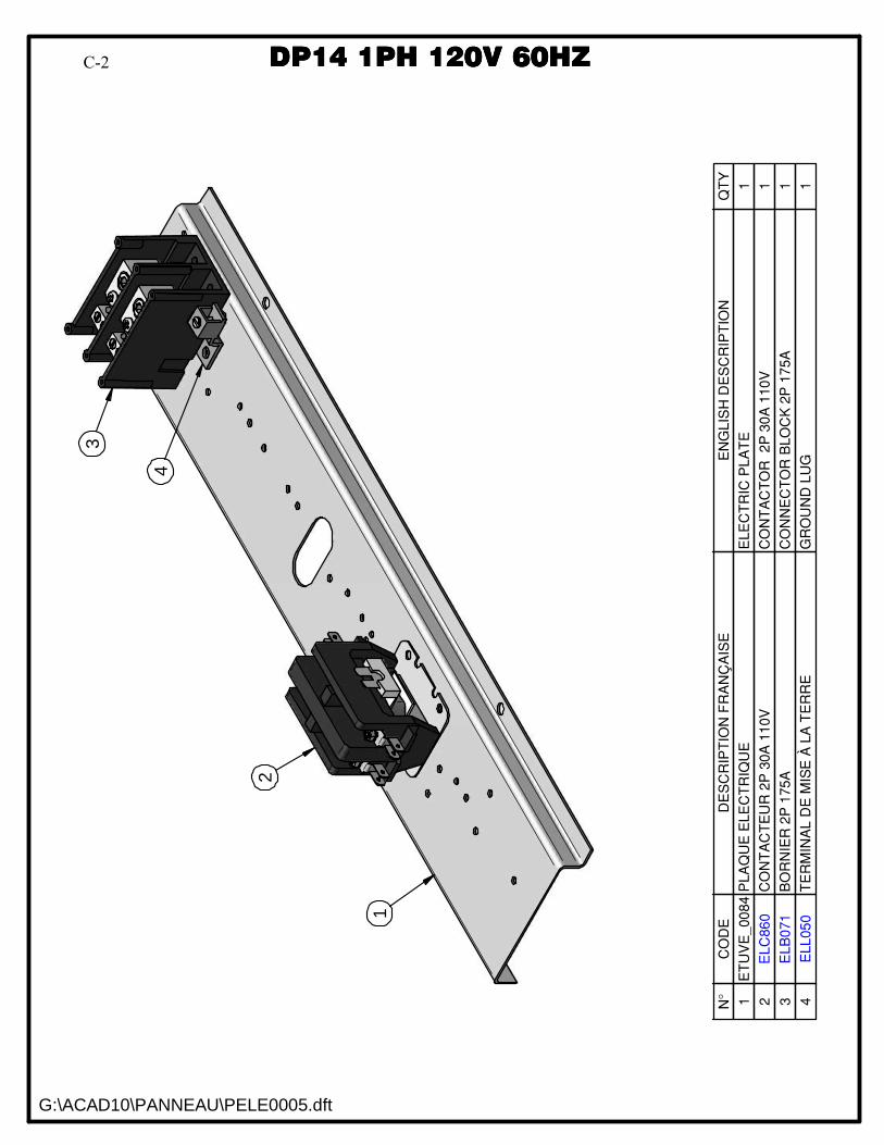
DP14 1PH 120V 60HZDP14 1PH 120V 60HZ
N°
CO
DE
DE
SC
RIP
TIO
N F
RA
NÇ
AIS
EE
NG
LIS
H D
ES
CR
IPT
ION
QT
Y
1E
TU
VE
_00
84
PLA
QU
E E
LE
CT
RIQ
UE
ELE
CT
RIC
PL
AT
E1
2E
LC
86
0C
ON
TA
CT
EU
R 2
P 3
0A
11
0V
CO
NT
AC
TO
R
2P
30
A 1
10
V1
3E
LB
071
BO
RN
IER
2P
175A
CO
NN
EC
TO
R B
LO
CK
2P
17
5A
1
4E
LL
05
0T
ER
MIN
AL
DE
MIS
E À
LA
TE
RR
EG
RO
UN
D L
UG
1
1
2
3
4
G:\ACAD10\PANNEAU\PELE0005.dft
DDDDPPPP11114444 1111PPPPHHHH 111122220000VVVV 66660000HHHHZZZZC-2
C-3
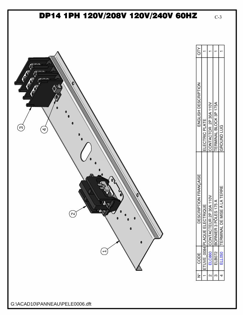
DP14 1PH 120V/208V 120V/240V 60HZDP14 1PH 120V/208V 120V/240V 60HZ
N°
CO
DE
DE
SC
RIP
TIO
N F
RA
NÇ
AIS
EE
NG
LIS
H D
ES
CR
IPT
ION
QT
Y
1E
TU
VE
_00
84
PLA
QU
E E
LE
CT
RIQ
UE
ELE
CT
RIC
PL
AT
E1
2E
LC
86
0C
ON
TA
CT
EU
R 2
P 3
0A
11
0V
CO
NT
AC
TO
R
2P
30
A 1
10
V1
3E
LB
072
BO
RN
IER
3 P
ÔLE
S 1
75
AT
ER
MIN
AL
BLO
CK
3P
17
5A
1
4E
LL
05
0T
ER
MIN
AL
DE
MIS
E À
LA
TE
RR
EG
RO
UN
D L
UG
1
1
2
4
G:\ACAD10\PANNEAU\PELE0006.dft
DDDDPPPP11114444 1111PPPPHHHH 111122220000VVVV////222200008888VVVV 111122220000VVVV////222244440000VVVV 66660000HHHHZZZZ3
C-3
C-4
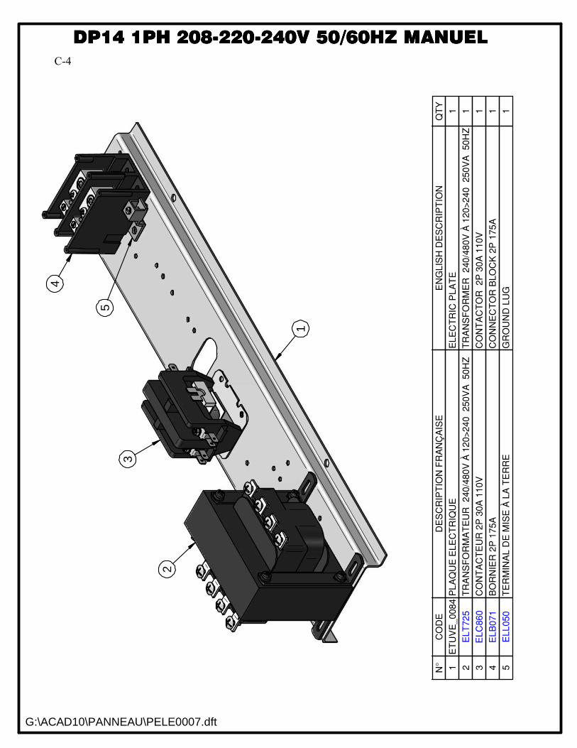
DP14 1PH 208-220-240V 50/60HZDP14 1PH 208-220-240V 50/60HZ
N°
CO
DE
DE
SC
RIP
TIO
N F
RA
NÇ
AIS
EE
NG
LIS
H D
ES
CR
IPT
ION
QT
Y
1E
TU
VE
_008
4P
LA
QU
E E
LE
CT
RIQ
UE
EL
EC
TR
IC P
LA
TE
1
2E
LT
72
5T
RA
NS
FO
RM
AT
EU
R
240
/480
V À
12
0>
24
0
250V
A
50
HZ
TR
AN
SF
OR
ME
R
240
/48
0V
À 1
20
>2
40
250
VA
50
HZ
1
3E
LC
860
CO
NT
AC
TE
UR
2P
30A
110
VC
ON
TA
CT
OR
2
P 3
0A
110V
1
4E
LB
07
1B
OR
NIE
R 2
P 1
75A
CO
NN
EC
TO
R B
LO
CK
2P
175
A1
5E
LL
050
TE
RM
INA
L D
E M
ISE
À L
A T
ER
RE
GR
OU
ND
LU
G1
3
5
G:\ACAD10\PANNEAU\PELE0007.dft
DDDDPPPP11114444 1111PPPPHHHH 222200008888----222222220000----222244440000VVVV 55550000////66660000HHHHZZZZ MMMMAAAANNNNUUUUEEEELLLL
1
2
4C-4

C-5
DP14 1PH 120V 60HZ AUTODP14 1PH 120V 60HZ AUTO
G:\ACAD10\PANNEAU\PELE0008.dft
DDDDPPPP11114444 1111PPPPHHHH 111122220000VVVV 66660000HHHHZZZZ AAAAUUUUTTTTOOOO
N°
CO
DE
DE
SC
RIP
TIO
N F
RA
NÇ
AIS
EE
NG
LIS
H D
ES
CR
IPT
ION
QT
Y
1E
TU
VE
_008
4P
LA
QU
E E
LE
CT
RIQ
UE
ELE
CT
RIC
PL
AT
E1
2E
LB
07
1B
OR
NIE
R 2
P 1
75A
CO
NN
EC
TO
R B
LO
CK
2P
17
5A
1
3E
LL0
50
TE
RM
INA
L D
E M
ISE
À L
A T
ER
RE
GR
OU
ND
LU
G1
4E
LC
615
RE
LA
IS 1
0A
2P
BO
BIN
E 1
10
VR
EL
AY
10
A 2
P C
OIL
110V
1
5E
LC
617
BA
SE
DE
RE
LA
IS 8
CO
NN
EC
TE
UR
BA
SE
RE
LA
Y 8
PIN
S1
6E
LM
736
RÉ
SIS
TA
NC
E 3
Kohm
s 5
WR
ES
IST
OR
3K
ohm
s 5
W1
7E
LC
640
BA
SE
DE
RE
LA
IS D
E C
ON
TR
ÔL
EC
ON
TR
OL
RE
LA
Y B
AS
E1
8E
LC
630
RE
LA
IS D
E C
ON
TR
ÔL
E 1
2A
BO
BIN
E 1
20V
CO
NT
RO
L R
ELA
Y
12A
CO
IL 1
20V
1
9E
LC
860
CO
NT
AC
TE
UR
2P
30A
11
0V
CO
NT
AC
TO
R
2P
30A
110
V1
10
ELM
735
MIN
UT
ER
IE I
CM
SO
LID
ST
AT
E T
IME
R IC
M1
1
23
5
4
6
7
8
9
10
C-5
C-6
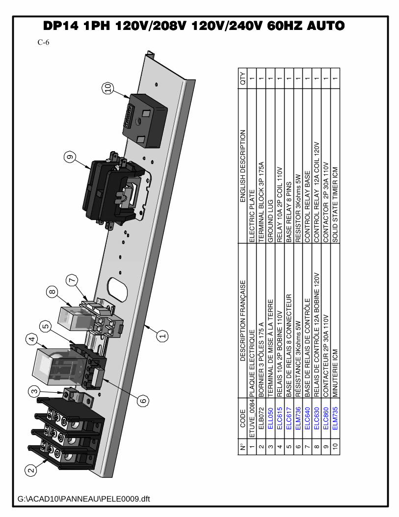
DP14 1PH 120V/208V 120V/240V 60HZ AUTODP14 1PH 120V/208V 120V/240V 60HZ AUTO
G:\ACAD10\PANNEAU\PELE0009.dft
DDDDPPPP11114444 1111PPPPHHHH 111122220000VVVV////222200008888VVVV 111122220000VVVV////222244440000VVVV 66660000HHHHZZZZ AAAAUUUUTTTTOOOO
N°
CO
DE
DE
SC
RIP
TIO
N F
RA
NÇ
AIS
EE
NG
LIS
H D
ES
CR
IPT
ION
QT
Y
1E
TU
VE
_008
4P
LA
QU
E E
LE
CT
RIQ
UE
ELE
CT
RIC
PL
AT
E1
2E
LB
07
2B
OR
NIE
R 3
PÔ
LE
S 1
75
AT
ER
MIN
AL
BLO
CK
3P
175A
1
3E
LL0
50
TE
RM
INA
L D
E M
ISE
À L
A T
ER
RE
GR
OU
ND
LU
G1
4E
LC
615
RE
LA
IS 1
0A
2P
BO
BIN
E 1
10
VR
EL
AY
10
A 2
P C
OIL
110V
1
5E
LC
617
BA
SE
DE
RE
LA
IS 8
CO
NN
EC
TE
UR
BA
SE
RE
LA
Y 8
PIN
S1
6E
LM
736
RÉ
SIS
TA
NC
E 3
Kohm
s 5
WR
ES
IST
OR
3K
ohm
s 5
W1
7E
LC
640
BA
SE
DE
RE
LA
IS D
E C
ON
TR
ÔL
EC
ON
TR
OL
RE
LA
Y B
AS
E1
8E
LC
630
RE
LA
IS D
E C
ON
TR
ÔL
E 1
2A
BO
BIN
E 1
20V
CO
NT
RO
L R
ELA
Y
12A
CO
IL 1
20V
1
9E
LC
860
CO
NT
AC
TE
UR
2P
30A
11
0V
CO
NT
AC
TO
R
2P
30A
110
V1
10
ELM
735
MIN
UT
ER
IE I
CM
SO
LID
ST
AT
E T
IME
R IC
M1
1
35
4
6
7
8
9
2
10
C-6
C-7
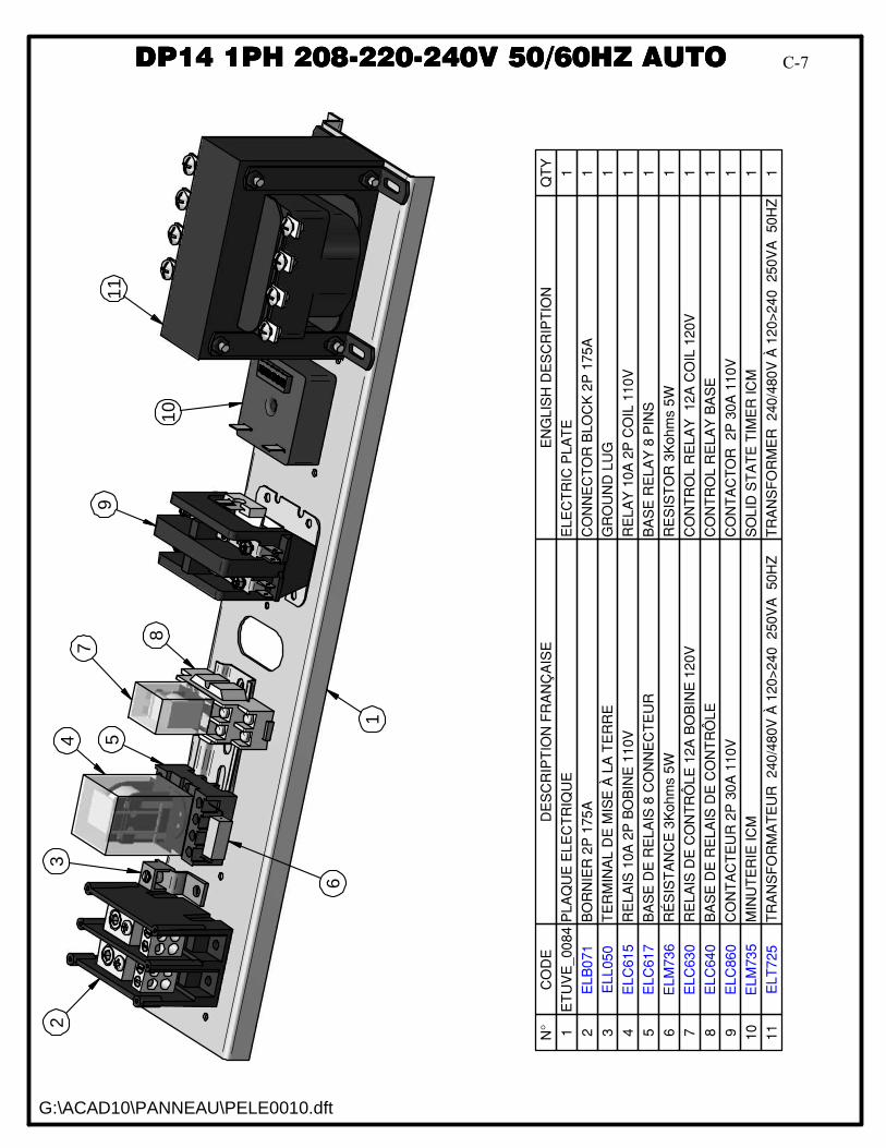
DP14 1PH 208-220-240V 50/60HZ AUTODP14 1PH 208-220-240V 50/60HZ AUTO
G:\ACAD10\PANNEAU\PELE0010.dft
DDDDPPPP11114444 1111PPPPHHHH 222200008888----222222220000----222244440000VVVV 55550000////66660000HHHHZZZZ AAAAUUUUTTTTOOOO
N°
CO
DE
DE
SC
RIP
TIO
N F
RA
NÇ
AIS
EE
NG
LIS
H D
ES
CR
IPT
ION
QT
Y
1E
TU
VE
_00
84
PLA
QU
E E
LE
CT
RIQ
UE
ELE
CT
RIC
PL
AT
E1
2E
LB
071
BO
RN
IER
2P
175
AC
ON
NE
CT
OR
BLO
CK
2P
175A
1
3E
LL
050
TE
RM
INA
L D
E M
ISE
À L
A T
ER
RE
GR
OU
ND
LU
G1
4E
LC
61
5R
EL
AIS
10A
2P
BO
BIN
E 1
10V
RE
LA
Y 1
0A
2P
CO
IL 1
10
V1
5E
LC
61
7B
AS
E D
E R
EL
AIS
8 C
ON
NE
CT
EU
RB
AS
E R
ELA
Y 8
PIN
S1
6E
LM
736
RÉ
SIS
TA
NC
E 3
Koh
ms 5
WR
ES
IST
OR
3K
oh
ms 5
W1
7E
LC
63
0R
EL
AIS
DE
CO
NT
RÔ
LE
12A
BO
BIN
E 1
20V
CO
NT
RO
L R
EL
AY
12
A C
OIL
120V
1
8E
LC
64
0B
AS
E D
E R
EL
AIS
DE
CO
NT
RÔ
LE
CO
NT
RO
L R
EL
AY
BA
SE
1
9E
LC
86
0C
ON
TA
CT
EU
R 2
P 3
0A
110V
CO
NT
AC
TO
R
2P
30A
11
0V
1
10
ELM
735
MIN
UT
ER
IE IC
MS
OL
ID S
TA
TE
TIM
ER
IC
M1
11
EL
T7
25
TR
AN
SF
OR
MA
TE
UR
2
40
/480V
À 1
20
>240
250V
A
50
HZ
TR
AN
SF
OR
ME
R
240
/480
V À
12
0>
24
0
250V
A
50
HZ
1
1
23
4 5
6
7
8
9
10
11
C-7

WARRANTY / GARANTIE
LIMITED WARRANTY(Continental United States Of America And Canada Only)
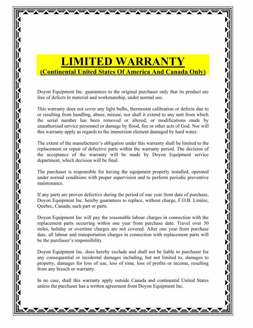
Doyon Equipment Inc. guarantees to the original purchaser only that its product arefree of defects in material and workmanship, under normal use.
This warranty does not cover any light bulbs, thermostat calibration or defects due toor resulting from handling, abuse, misuse, nor shall it extend to any unit from whichthe serial number has been removed or altered, or modifications made byunauthorised service personnel or damage by flood, fire or other acts of God. Nor willthis warranty apply as regards to the immersion element damaged by hard water.
The extent of the manufacturer�s obligation under this warranty shall be limited to thereplacement or repair of defective parts within the warranty period. The decision ofthe acceptance of the warranty will be made by Doyon Equipment servicedepartment, which decision will be final.
The purchaser is responsible for having the equipment properly installed, operatedunder normal conditions with proper supervision and to perform periodic preventivemaintenance.
If any parts are proven defective during the period of one year from date of purchase,Doyon Equipment Inc. hereby guarantees to replace, without charge, F.O.B. Linière,Quebec, Canada, such part or parts.
Doyon Equipment Inc will pay the reasonable labour charges in connection with thereplacement parts occurring within one year from purchase date. Travel over 50miles, holiday or overtime charges are not covered. After one year from purchasedate, all labour and transportation charges in connection with replacement parts willbe the purchaser�s responsibility.
Doyon Equipment Inc. does hereby exclude and shall not be liable to purchaser forany consequential or incidental damages including, but not limited to, damages toproperty, damages for loss of use, loss of time, loss of profits or income, resultingfrom any breach or warranty.
In no case, shall this warranty apply outside Canada and continental United Statesunless the purchaser has a written agreement from Doyon Equipment Inc.
GARANTIE LIMITÉE(Pour le Canada et les États continentaux des États-Unis)
Équipement Doyon Inc. garantit ses produits à l'acheteur original, contre tout défautde matériaux ou de fabrication, en autant qu'ils aient été utilisés de façon normale.
Cette garantie ne s'applique cependant pas sur les ampoules, les calibrations detempérature, tout défaut dû ou résultant d'une mauvaise manipulation, d'un emploiabusif ou d'un mauvais usage. La garantie ne s'applique pas non plus sur toutéquipement dont le numéro de série aurait été enlevé ou altéré, tout produit modifiépar du personnel de service non autorisé, endommagé par une inondation, un feu outout autre acte de Dieu, ni sur les éléments immergés endommagés par l'eau dure.
L'étendue des obligations du manufacturier, selon cette garantie, est le remplacementou la réparation des pièces défectueuses durant la période de garantie. L'acceptationde la garantie sera faite par le département de service d'Équipement Doyon Inc.Cette décision sera définitive.
L'acheteur est responsable de faire installer son équipement adéquatement, del'opérer sous des conditions normales d'utilisation avec une bonne supervision, ainsique d'effectuer un entretien préventif périodique.
Dans le cas où les pièces s'avéreraient défectueuses durant une période d'un an àpartir de la date d'achat, Équipement Doyon Inc. s'engage à les remplacer, sansfrais, F.O.B. Linière, Québec, Canada.
Équipement Doyon Inc. couvrira les frais raisonnables de main-d'�uvre reliés auremplacement des pièces, pour une période d'un an à partir de la date d'achat.Toutefois, les frais encourus pour les déplacements au-delà de 50 milles, le tempssupplémentaire et les jours de congé ne sont pas couverts. Au-delà d'un an après ladate d'achat, tous frais de transport et de main-d'�uvre pour le remplacement despièces sont la responsabilité de l'acheteur.
Équipement Doyon Inc. ne se tient pas responsable envers l'acheteur pour toutesconséquences ou dommages incluant, mais non limités à, dommages à la propriété,dommages pour perte d'usage, perte de temps, perte de profits ou de revenus,provenant de tout bris de garantie.
En aucun cas, cette garantie ne s'applique à l'extérieur du continent des États-Unisd'Amérique ou du Canada, à moins que l'acheteur n'ait une entente écrite avecÉquipement Doyon Inc.
ÉQUIPEMENT DOYON INC.1255, rue Principale
Linière, Qc, Canada G0M 1J0
Tel.: 1 (418) 685-3431Canada: 1 (800) 463-1636
US: 1 (800) 463-4273FAX: 1 (418) 685-3948
Internet: http://www.doyon.qc.cae-mail: [email protected]
![Lindemann DP14 [Formatted] › international-development › ...Stefan Lindemann Development Studies Institute, LSE Abstract Sub-Saharan Africa combines all the major risk factors](https://img.pdfslide.us/doc/110x75/60d3c5d1da12181afc5def51/lindemann-dp14-formatted-a-international-development-a-stefan-lindemann.jpg)
![Lindemann DP14 [Formatted]...2 Table 1: Civil war onset vs. avoidance in Sub-Sahara Africa (1945-2007)3 Countries having experienced civil war (24) Countries having avoided civil war](https://img.pdfslide.us/doc/110x75/5ff8a5888a373041ff0bacf5/lindemann-dp14-formatted-2-table-1-civil-war-onset-vs-avoidance-in-sub-sahara.jpg)


![DP13[CH/HH] 13 SEER & DP14[CH/HH] 14 SEER ... - … ... Contactor ... cation sheets can be found at for Daikin brand products. Within the website, please select the residen-](https://img.pdfslide.us/doc/110x75/5b1dd2447f8b9a8e158bd705/dp13chhh-13-seer-dp14chhh-14-seer-contactor-cation-sheets.jpg)