Embed Size (px)
Citation preview
GOVERNMENT OF THE DISTRICT OF COLUMBIA
DEPARTMENT OF PUBLIC WORKSOFFICE OF INTERMODAL PLANNING
AUGUST 2000
D O W N T O W N
S T R E E T S C A P ER E G U L A T I O N S
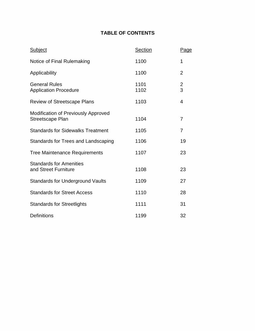
TABLE OF CONTENTS
Subject Section Page
Notice of Final Rulemaking 1100 1
Applicability 1100 2
General Rules 1101 2Application Procedure 1102 3
Review of Streetscape Plans 1103 4
Modification of Previously ApprovedStreetscape Plan 1104 7
Standards for Sidewalks Treatment 1105 7
Standards for Trees and Landscaping 1106 19
Tree Maintenance Requirements 1107 23
Standards for Amenitiesand Street Furniture 1108 23
Standards for Underground Vaults 1109 27
Standards for Street Access 1110 28
Standards for Streetlights 1111 31
Definitions 1199 32
EXHIBITS
Title Page
A. Description of Downtown Streetscape Impact AreaBoundaries and Map 34
B. Specifications for Concrete Block Paving 36
C. Master Street Tree Plan 40
This document was prepared byEdith R. Fitzhugh, Executive Secretary
Downtown Streetscape CommitteeDepartment of Public Works
AndLewis Booker and Lito Tongson
DC Downtown Business Improvement District
These regulations include design elements in theDowntown DC Business Improvement District
Streetscape Enhancement Notebook, August 1999
DEPARTMENT OF PUBLIC WORKS_____________________________________
NOTICE OF FINAL RULEMAKING_____________________________________
The Director of the Department of Public Works, pursuant to the authority of Sections IV(A) andV of Reorganization Plan No. 4 of 1983, 30 DCR 6428 (December 16, 1983), effective March 2,1984, and Mayor's Order 84-55, 31 DCR 1323 (March 16, 1984), hereby gives notice of theadoption of the following rules which amend the Public Space and Safety Regulations (24DCMR). Comments have been received and one minor clarifying change has been made toSection 1108.5 (d) of the proposed rules as published on June 30, 2000, edition of the D.C.Register (47 DCR 5460). The final rules will delete obsolete information, and include additionsand revisions to provide streetscape enhancements. This final rulemaking will be effectivewhen published in the D.C. Register.
Title 24, Chapter 11, DOWNTOWN STREETSCAPE, is amended in its entirety to read asfollows:
1
CHAPTER 11 DOWNTOWN STREETSCAPE
1100 APPLICABILITY
1100.1 This chapter shall apply to any person engaged in redevelopment or substantialrehabilitation, including sidewalk rehabilitation, where more than 50 percent ofthe sidewalk area adjoining a project is planned for construction, within theDowntown Streetscape Area.
1100.2 The boundaries of the Downtown Streetscape Area approximate the designatedboundaries for the Downtown Urban Renewal Area and are defined in Exhibit Aof these regulations.
1101 GENERAL RULES
1101.1 This chapter sets forth-minimum standards for the treatment of the public spacein the Downtown Streetscape Area. Applicants may request variations andmodifications to these standards that raise the quality of the materials used or thedesign of the public space.
1101.2 Recycled materials shall be used to meet the requirements of these regulationswhenever possible.
1101.3 Except as provided in subsection 1101.5, the Director shall not approve theissuance of a permit listed in Subsection 1101.4 to any person unless theDirector has approved a Step 1 streetscape plan pursuant to section 1103.
1101.4 Subsection 1101.3 shall apply to the recommendation for approval of thefollowing permits:
(a) Excavation;(b) Footings; and(c) Location of manholes and other vaults as part of a building permit.
1101.5 Approval of the Step I streetscape plan is not required for the issuance of anexcavation permit to remove or relocate a utility vault to prepare a site for projectdevelopment.
1101.6 The Director shall not approve the issuance of a permit listed in subsection1101.7 to any person unless the Director has approved a Step 2 streetscape planpursuant to section 1103 or unless the Director has approved a combinedstreetscape plan pursuant to subsection 1102.5.
1101.7 Subsection 1101.6 shall apply to the following permits:
(a) Paving parking;(b) Paving sidewalk, alleys, curb, and gutters;
2
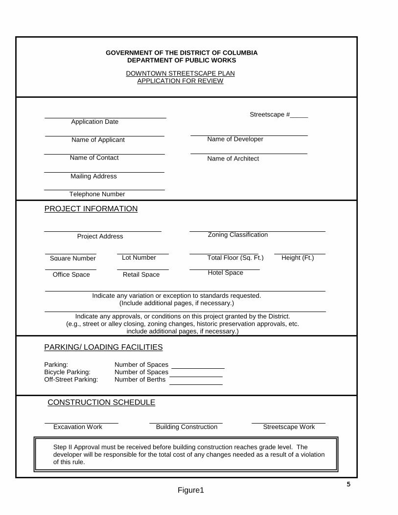
PROJECT INFORMATION
Step II Approval must be received before building construction reaches grade level. Thedeveloper will be responsible for the total cost of any changes needed as a result of a violationof this rule.
Zoning Classification
Lot Number
Application Date
Name of Applicant
Name of Contact
Mailing Address
Telephone Number
Name of Developer
Name of Architect
Project Address
Square Number
Office Space Retail Space Hotel Space
Height (Ft.)Total Floor (Sq. Ft.)
Indicate any variation or exception to standards requested.(Include additional pages, if necessary.)
Indicate any approvals, or conditions on this project granted by the District.(e.g., street or alley closing, zoning changes, historic preservation approvals, etc.
include additional pages, if necessary.)
PARKING/ LOADING FACILITIES
Parking: Number of SpacesBicycle Parking: Number of SpacesOff-Street Parking: Number of Berths
CONSTRUCTION SCHEDULE
Excavation Work Building Construction Streetscape Work
GOVERNMENT OF THE DISTRICT OF COLUMBIADEPARTMENT OF PUBLIC WORKS
DOWNTOWN STREETSCAPE PLANAPPLICATION FOR REVIEW
Figure1
Streetscape #_____
5
(c) Fence, retaining walls, and hedges;(d) Grading, alleys, and roadways; and(e) Driveways.
1101.8 Streetscape Plan approvals shall expire if the appropriate Public space permitshave not been secured and construction started within one year of the approvals.
1102 APPLICATION PROCEDURE
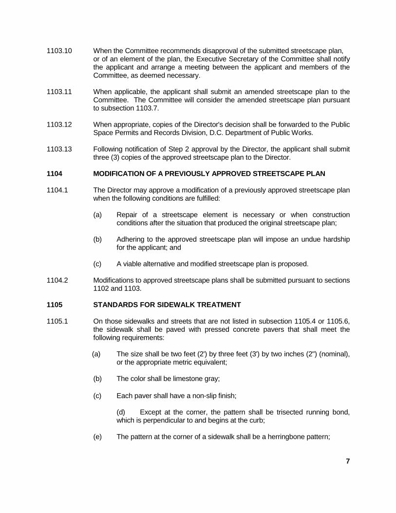
1102.1 To obtain a Step 1 streetscape review of a streetscape plan, an applicant shallsubmit an application on a form (Figure1) provided by the Director and ten (10)copies of the streetscape plan as part of the public space permit applicationprocess.
1102.2 The streetscape plan submitted for the Step 1 streetscape review should show, ifknown, the following:
(a) Sidewalk treatment including proposed materials and paving patterns;
(b) The location and type of all existing and proposed streetlights, trafficsignals, parking signs, other traffic control devices and parking meters;
(c) The location of existing and proposed tree spaces, tree species andproposed tree planting details;
(d) The location, design and dimension of all existing and proposeddriveways and curb cuts, sewer and water connections, utility lines, andoil tank openings;
(e) The length of the radii for all driveways, alleys, and street corners;
(f) Vaults or any other underground projection below public space, sidewalksor alleys;
(g) Metrobus stops, bus shelters, and Metrorail station entrances;
(h) The location and size of pedestrian entrances, including, but not limitedto, store entrances and through-building passageways;
(i) The size and location of shop windows;
(j) The location and design of loading berths, taxi, bus, and other vehiclequeuing, waiting areas, or other drop-off or pick-up areas and facilities.The plans for loading berths shall include the number of berths anddetails of access to the berths;
(k) Top of curb profiles, alley profiles, sidewalk cross slopes, and final streetgrades;
3
(l) The location of street amenities;
(m) Elevation of any portion of the building facing a street; and
(n) Handicap ramp locations and details.
1102.3 To obtain a Step 2 Streetscape review of a streetscape plan, an applicant shallsubmit ten (IO) copies of the streetscape plan as part of the public space permitapplication process.
1102.4 The streetscape plan submitted for the Step 2 Streetscape review shall show thefollowing:
(a) The actual paving materials, their design and support details, landscapingtreatment and planting details, final sidewalk grades and any streetscapeamenities with necessary details for installation, and drainage details;
(b) Design and location of the sidewalk level streetscape elements, includingbut not limited to, the designated tree species, tree box plantings, specificdesigns, number and location of any streetscape hardware, pedestrianamenities, and decorative fixtures; and
(c) The treatment of vault covers.
1102.5 Applicant may, subject to approval by the Director, submit a combinedstreetscape plan that shows the elements required by subsections 1102.2 and1102.4. A combined streetscape plan shall be submitted pursuant to the timeperiod set for a Step 1 Streetscape plan.
1102.6 The applicant shall clearly indicate on the submitted streetscape plan anyvariation or exception to the standards set forth in this chapter and the applicantshall provide a letter describing the variation or the exception and its underlyingrationale.
1102.7 All drawings for a Step 1 or a Step 2 Streetscape review shall be submitted to theExecutive Secretary, Downtown Streetscape Review Committee, Department ofPublic Works, 7th floor, 2000 14th Street, NW, Washington, D.C.
REVIEW OF STREETSCAPE PLANS
1103.1 The Director shall review the submitted streetscape plans to ensure that thesubmitted streetscape plan and the application have all the required andnecessary information.
1103.2 The Director shall notify the applicant within five (5) working days of theadequacy of the information included in the submitted streetscape plan. Whennecessary, the streetscape plan shall be returned to the applicant for theinclusion of any information that is required or necessary.
4
1103.3 The applicant may request, and the Director may grant, upon good cause shown,that the streetscape plan be reviewed in an expeditious manner.
1103.4 The Director shall convene a committee to review a submitted streetscape planand to provide a recommendation to the Director on whether the Director shouldapprove or disapprove the submitted streetscape plan.
1103.5 The Committee shall be appointed by the Director and shall consist ofrepresentatives of the Design, Engineering and Construction Administration, theWater and Sewer Utility Authority, the Transportation Systems Administration,the Public Space Maintenance Administration and the Office of Policy andPlanning.
1103.6 The Director shall request that a representative from the Office of Planning, theAmerican Institute of Architects and the American Society of LandscapeArchitects serve as advisory members to the Committee.
1103.7 The Committee shall, within three (3) weeks of the submission of the streetscapeplan, review the streetscape plan to determine if the streetscape plan conforms tothe requirements of this chapter and recommend to the Director whether thestreetscape plan (and any requested variation or exception to the standards) shouldbe approved, disapproved, or modified.
1103.8 Variations or exceptions may be recommended for approval if the applicant hasdemonstrated that the following conditions (a) through (c) have been satisfied orthat condition (d) has been adequately demonstrated:
(a) The exception or variation will improve or raise the quality of the streetscapematerials or improve or raise the quality of the design of the public space;
(b) The exception or variation is compatible with the adjoining sidewalk andpublic space;
(c) That if the project is an historic landmark or in an historic district, theexception or variation is compatible with the historic landmark or historicdistrict; and
(d) Compliance with these rules or any provision thereof imposes an unduehardship on the applicant.
1103.9 Except as provided for in subsection 1103.10, the applicant shall be notified withinfive (5) business days of the date the Director receives the Committees'srecommendation. Written notification of the decision shall be transmitted to theapplicant within ten (10) working days of the Director's decision.
6
1103.10 When the Committee recommends disapproval of the submitted streetscape plan,or of an element of the plan, the Executive Secretary of the Committee shall notifythe applicant and arrange a meeting between the applicant and members of theCommittee, as deemed necessary.
1103.11 When applicable, the applicant shall submit an amended streetscape plan to theCommittee. The Committee will consider the amended streetscape plan pursuantto subsection 1103.7.
1103.12 When appropriate, copies of the Director's decision shall be forwarded to the PublicSpace Permits and Records Division, D.C. Department of Public Works.
1103.13 Following notification of Step 2 approval by the Director, the applicant shall submitthree (3) copies of the approved streetscape plan to the Director.
1104 MODIFICATION OF A PREVIOUSLY APPROVED STREETSCAPE PLAN
1104.1 The Director may approve a modification of a previously approved streetscape planwhen the following conditions are fulfilled:
(a) Repair of a streetscape element is necessary or when constructionconditions after the situation that produced the original streetscape plan;
(b) Adhering to the approved streetscape plan will impose an undue hardshipfor the applicant; and
(c) A viable alternative and modified streetscape plan is proposed.
1104.2 Modifications to approved streetscape plans shall be submitted pursuant to sections1102 and 1103.
1105 STANDARDS FOR SIDEWALK TREATMENT
1105.1 On those sidewalks and streets that are not listed in subsection 1105.4 or 1105.6,the sidewalk shall be paved with pressed concrete pavers that shall meet thefollowing requirements:
(a) The size shall be two feet (2') by three feet (3') by two inches (2") (nominal),or the appropriate metric equivalent;
(b) The color shall be limestone gray;
(c) Each paver shall have a non-slip finish;
(d) Except at the corner, the pattern shall be trisected running bond,which is perpendicular to and begins at the curb;
(e) The pattern at the corner of a sidewalk shall be a herringbone pattern;
7
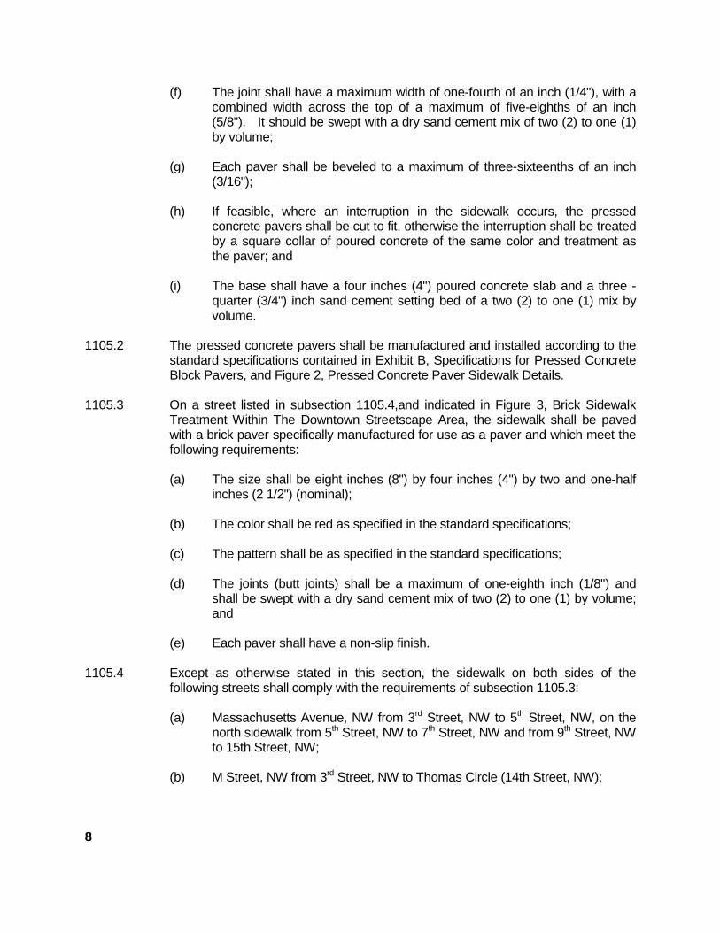
(f) The joint shall have a maximum width of one-fourth of an inch (1/4"), with acombined width across the top of a maximum of five-eighths of an inch(5/8"). It should be swept with a dry sand cement mix of two (2) to one (1)by volume;
(g) Each paver shall be beveled to a maximum of three-sixteenths of an inch(3/16");
(h) If feasible, where an interruption in the sidewalk occurs, the pressedconcrete pavers shall be cut to fit, otherwise the interruption shall be treatedby a square collar of poured concrete of the same color and treatment asthe paver; and
(i) The base shall have a four inches (4") poured concrete slab and a three -quarter (3/4") inch sand cement setting bed of a two (2) to one (1) mix byvolume.
1105.2 The pressed concrete pavers shall be manufactured and installed according to thestandard specifications contained in Exhibit B, Specifications for Pressed ConcreteBlock Pavers, and Figure 2, Pressed Concrete Paver Sidewalk Details.
1105.3 On a street listed in subsection 1105.4,and indicated in Figure 3, Brick SidewalkTreatment Within The Downtown Streetscape Area, the sidewalk shall be pavedwith a brick paver specifically manufactured for use as a paver and which meet thefollowing requirements:
(a) The size shall be eight inches (8") by four inches (4") by two and one-halfinches (2 1/2") (nominal);
(b) The color shall be red as specified in the standard specifications;
(c) The pattern shall be as specified in the standard specifications;
(d) The joints (butt joints) shall be a maximum of one-eighth inch (1/8") andshall be swept with a dry sand cement mix of two (2) to one (1) by volume;and
(e) Each paver shall have a non-slip finish.
1105.4 Except as otherwise stated in this section, the sidewalk on both sides of thefollowing streets shall comply with the requirements of subsection 1105.3:
(a) Massachusetts Avenue, NW from 3rd Street, NW to 5th Street, NW, on thenorth sidewalk from 5th Street, NW to 7th Street, NW and from 9th Street, NWto 15th Street, NW;
(b) M Street, NW from 3rd Street, NW to Thomas Circle (14th Street, NW);
8
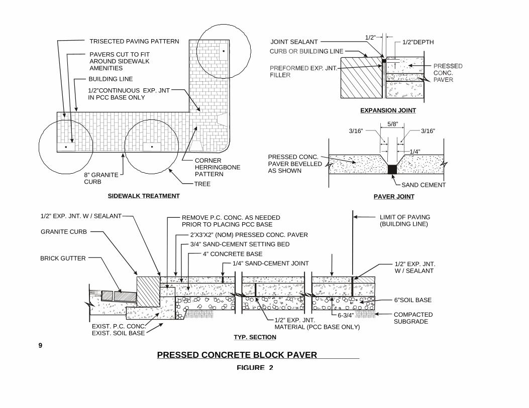
FIGURE 2
PRESSED CONCRETE BLOCK PAVER
BRICK GUTTER
GRANITE CURB
1/2” EXP. JNT. W / SEALANT REMOVE P.C. CONC. AS NEEDEDPRIOR TO PLACING PCC BASE
2’X3’X2” (NOM) PRESSED CONC. PAVER
3/4” SAND-CEMENT SETTING BED
4” CONCRETE BASE
LIMIT OF PAVING(BUILDING LINE)
1/2” EXP. JNT.W / SEALANT
1/2” EXP. JNT.MATERIAL (PCC BASE ONLY)EXIST. P.C. CONC.
EXIST. SOIL BASE
6”SOIL BASE
1/4” SAND-CEMENT JOINT
6-3/4” COMPACTEDSUBGRADE
EWF
LB
TRISECTED PAVING PATTERN
PAVERS CUT TO FITAROUND SIDEWALKAMENITIES
1/2”CONTINUOUS EXP. JNTIN PCC BASE ONLY
CORNERHERRINGBONEPATTERN
BUILDING LINE
8” GRANITECURB
SIDEWALK TREATMENT
5/8”
1/4”
3/16”3/16”
PRESSED CONC.PAVER BEVELLEDAS SHOWN
SAND CEMENT
JOINT SEALANT1/2”
1/2”DEPTH
PAVER JOINT
EXPANSION JOINT
9
TREE
TYP. SECTION
NationalArchives
NorthNot to scale
FIGURE 3 SIDEWALK TREATMENT WITHIN THE DOWNTOWN STREETSCAPE AREA
Standard Brick TreatmentChinatown Brick Treatment
No
rth
C
ap
ito
l S
tre
et
Lo
ui s
i an
a
A
v e.
15 t
h S
t.
Make A Difference Pavers
P e n n s y l v a n i a A v e n u e
N e w Yo r k
Av e .
M a s s a c h u s e t t s A v e .
Ne
w J
er
se
y Av
en
ue
Ve
rm
on
t
Av
e.
K S t .
S t .
H
G
F 9th S
t.
6 t
h S
t.
K S t .
L
I
S t .
S t .
S t .
5 t
h S
t.
E
D
S t .
S t .
7 t
h S
t.
8 t
h S
t.
10 t
h S
t.
11 t
h S
t.
12 t
h S
t.
13 t
h S
t.
14 t
h S
t.
S t .
16 t
h S
t.
M S t .
4 t
h S
t.
3 r
d S
t.
C S t .
G P la ce No
rt h
Ca
pi to
l Str
ee
t
15 t
h S
t.
I n d i a n a A v e .
10
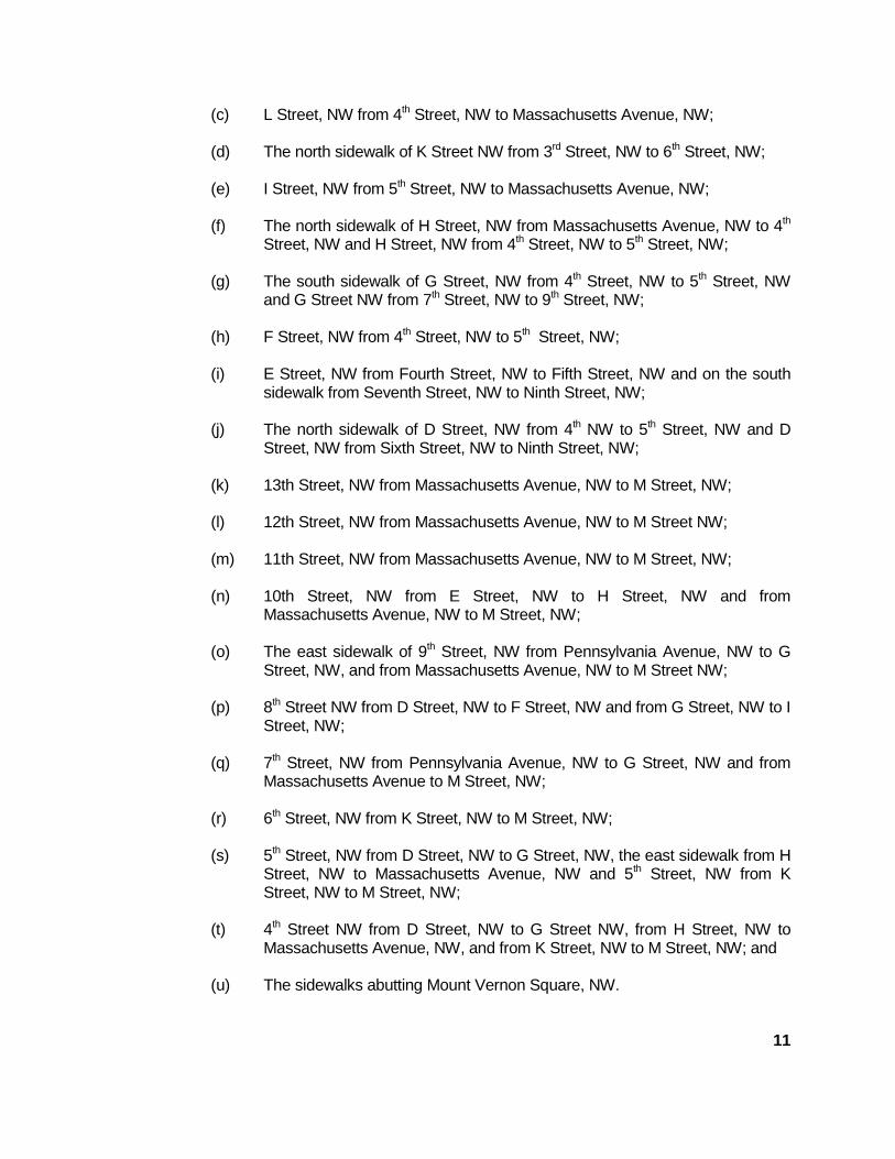
(c) L Street, NW from 4th Street, NW to Massachusetts Avenue, NW;
(d) The north sidewalk of K Street NW from 3rd Street, NW to 6th Street, NW;
(e) I Street, NW from 5th Street, NW to Massachusetts Avenue, NW;
(f) The north sidewalk of H Street, NW from Massachusetts Avenue, NW to 4th
Street, NW and H Street, NW from 4th Street, NW to 5th Street, NW;
(g) The south sidewalk of G Street, NW from 4th Street, NW to 5th Street, NWand G Street NW from 7th Street, NW to 9th Street, NW;
(h) F Street, NW from 4th Street, NW to 5th Street, NW;
(i) E Street, NW from Fourth Street, NW to Fifth Street, NW and on the southsidewalk from Seventh Street, NW to Ninth Street, NW;
(j) The north sidewalk of D Street, NW from 4th NW to 5th Street, NW and DStreet, NW from Sixth Street, NW to Ninth Street, NW;
(k) 13th Street, NW from Massachusetts Avenue, NW to M Street, NW;
(l) 12th Street, NW from Massachusetts Avenue, NW to M Street NW;
(m) 11th Street, NW from Massachusetts Avenue, NW to M Street, NW;
(n) 10th Street, NW from E Street, NW to H Street, NW and fromMassachusetts Avenue, NW to M Street, NW;
(o) The east sidewalk of 9th Street, NW from Pennsylvania Avenue, NW to GStreet, NW, and from Massachusetts Avenue, NW to M Street NW;
(p) 8th Street NW from D Street, NW to F Street, NW and from G Street, NW to IStreet, NW;
(q) 7th Street, NW from Pennsylvania Avenue, NW to G Street, NW and fromMassachusetts Avenue to M Street, NW;
(r) 6th Street, NW from K Street, NW to M Street, NW;
(s) 5th Street, NW from D Street, NW to G Street, NW, the east sidewalk from HStreet, NW to Massachusetts Avenue, NW and 5th Street, NW from KStreet, NW to M Street, NW;
(t) 4th Street NW from D Street, NW to G Street NW, from H Street, NW toMassachusetts Avenue, NW, and from K Street, NW to M Street, NW; and
(u) The sidewalks abutting Mount Vernon Square, NW.
11
1105.5 On a street listed in subsection 1105.6 in the Chinatown area, as defined by theOffice of Planning, and indicated in Figure 3, Chinatown brick sidewalk treatmentshall be paved with brick pavers and decorative pavers as specified by theCommittee and which shall meet the following requirements:
(a) The brick size shall be eight inches (8") by four inches (4") by two and one -half inches (2 1/2");
(b) The decorative brick paver size shall be eight inches (8") by eight inches(8") by two and one-half inches (2 1/2");
(c) The color of the decorative brick paver shall be red as specified in thestandard specifications;
(d) Except adjacent to the building, the brick pattern shall be a basket weavepattern, which begins at the curb;
(e) The brick pattern adjacent to the building shall be a soldier course on itsside, perpendicular to the building;
(f) The decorative brick paver shall be located in a random pattern, one foreach 200 square feet of a sidewalk;
(g) The design layout of the decorative brick paver shall be approved by theDirector;
(h) The Joint (butt joint) shall be at a maximum of one-eighth (1/8) of an inchand shall be swept with dry sand cement mix of two (2) to one (1) byvolume; and
(i) The adjacent Property owner shall purchase and store at the site extradecorative brick pavers.
1105.6 Except as otherwise stated in this section, the sidewalks on both sides of thefollowing streets shall comply with the requirements of subsection 1105.5.
(a) The south sidewalk of Massachusetts Avenue, NW from 5th Street, NW to7th Street, NW;
(b) I Street, NW from 5th Street, NW to 9th Street, NW;
(c) H Street, NW from 5th Street, NW to 9th Street, NW;
(d) The north sidewalk of G Street, NW from5th Street, NW to 6th Street, NW and7th Street, NW to 9th Street, NW;
12
(e) 7th Street, NW from G Street NWto Massachusetts Avenue, NW;
(f) 6th Street, NW from G Street, NWto Massachusetts Avenue, NW;
(g) The west sidewalk of 5th Street, NW fromG Street, NW to Massachusetts Avenue, NW; and
(h) The east sidewalk of 9th Street, NW fromG Street, NW to I Street, NW.
1105.7 Pavers with markers in the Make A Difference designated locations shall complywith the criteria in the District of Columbia Code, Chapter 2. Streets, Section 7-233and the locations in Section 7-236. (See Figure 3) Marker locations are thefollowing:
(a) The North and South sidewalks of F and G Streets, NW between 11th and15th Streets, NW;
(b) The North sidewalks of E Street, NW, between 11th and 14th Streets, NWand the South sidewalk of E Street, NW between 11th and 13th Streets, NW;
(c) The East sidewalks of 15th Street, NW, between Pennsylvania Avenue, NWand G Street, NW;
(d) The East and West sidewalks of 14th Street, NW. between PennsylvaniaAvenue, NW and G Street, NW;
(e) The East sidewalks of 13th Street, NW between Pennsylvania Avenue, NWand E Street, NW and the East and West sidewalks of 13th Street, NWbetween E and G Streets, NW; and
(f) The East and West sidewalks of 11th and 12th Streets, NW betweenPennsylvania Avenue, NW and G Street, NW.
1105.8 Personalized Pavers and Markers shall comply with Title 24 DCMR, Chapter 33,Section 3301, Occupation of Public Sidewalks with Personalized Pavers andMarkers.
1105.9 Variations in the predominant paving material may be made at building entrancesand along the building line. These variations are subject to Committee approvalwith the following provisions:
(a) The adjacent Property owner shall be responsible for the maintenance ofany nonstandard paving material and design;
13
(b) At the entry to buildings, paving may be varied for up to one-third (1/3) of thedistance from the property line to the face of the curb and for a width not toexceed twice the doorway size;
(c) The adjacent property owner shall always maintain and store at the site anextra ten percent (10%) of the nonstandard paving material; and
(d) Variations may include special designs, mosaics, and other designstatements.
1105.10 The surface of a brick paver or a pressed concrete paver shall be non-slip.
1105.11 Large rough exposed aggregates in the sidewalk paving treatment shall not beapproved.
1105.12 Smaller pressed concrete pavers or brick pavers, paved concrete, or other pavingtreatments may be approved where grade problems can not be resolved by anyother method.
1105.13 Expansion joints between pavers and other elements shall not be greater thanthree-quarters (3/4") of an inch and shall be filled with caulking material.
1105.14 Driveways shall be paved in a manner that distinguishes the driveway from thesidewalk and the street.
1105.15 Ramps for use by the handicapped shall meet the following requirements:
(a) The standard material shall be concrete and color shall be lighter thanadjoining pavement;
(b) Handicap ramps shall be located within the parallel lines and aligned withthe back edge of the crosswalk;
(c) There shall be 5 ft. clearance at top of ramp; and
(d) Ramp shall conform to the requirements as specified in the standardspecifications and in Figure 4 and Figure 4A, Wheelchair Ramp.
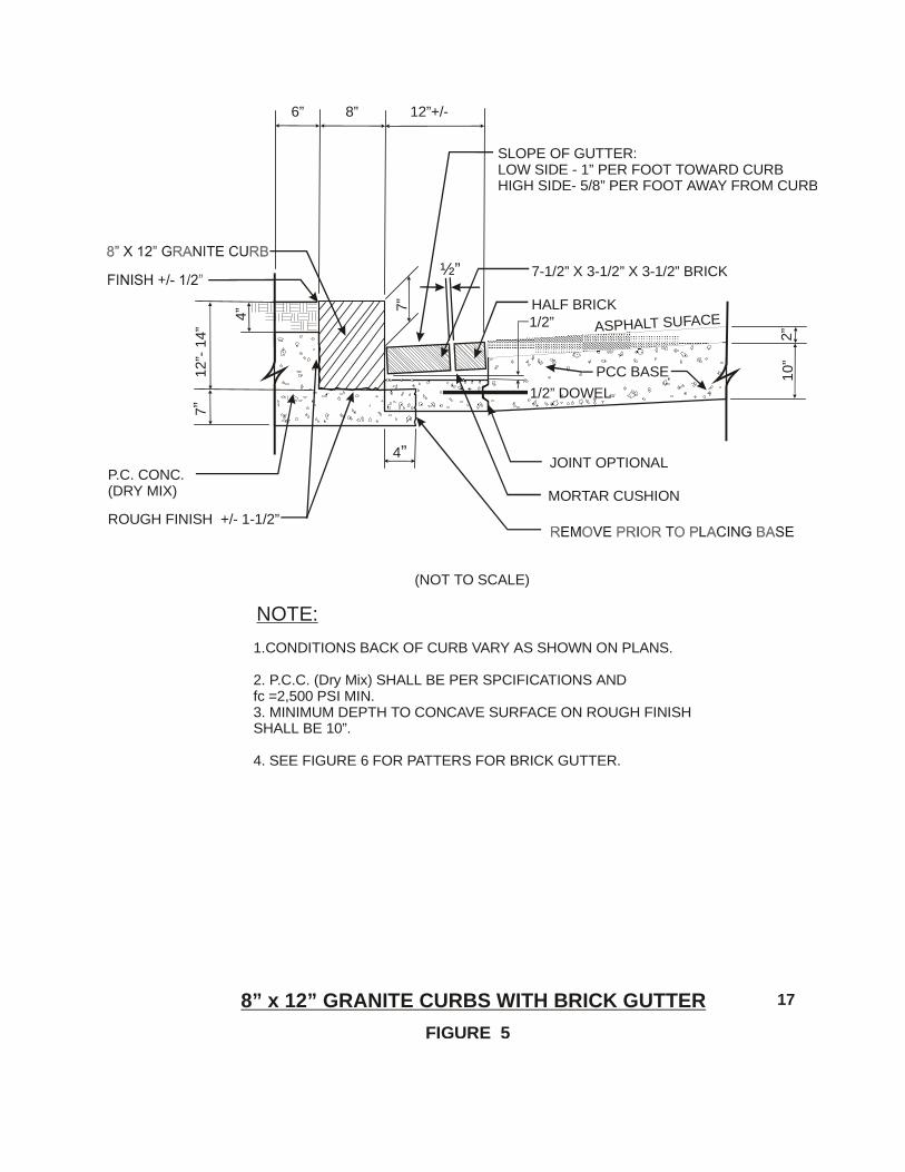
1105.16 New granite curbs shall be installed on all streets in the Downtown StreetscapeArea according to Figure 5.
1105.17 New brick gutters shall be installed on all streets in the Downtown Streetscape Areaaccording to Figure 6, Pattern for Brick Gutter.
1105.18 The crosswalk treatment shall conform to the requirements as specified in thestandard specifications.
14
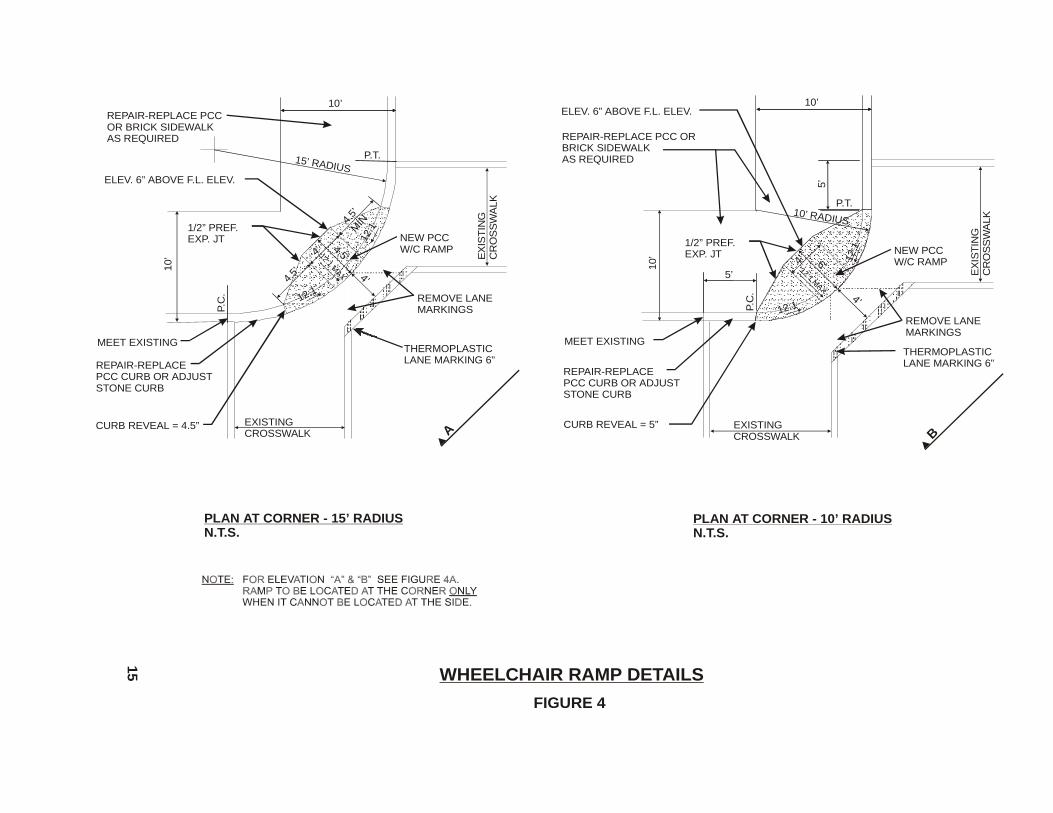
WHEELCHAIR RAMP DETAILS
FIGURE 4
PLAN AT CORNER - 15’ RADIUSN.T.S.
15’ RADIUS
1/2” PREF.EXP. JT
10’
10’
ELEV. 6” ABOVE F.L. ELEV.
P.T.
P.C
.
MEET EXISTING
REPAIR-REPLACEPCC CURB OR ADJUSTSTONE CURB
CURB REVEAL = 4.5”
REMOVE LANEMARKINGS
REPAIR-REPLACE PCC OR BRICK SIDEWALK AS REQUIRED
EXISTINGCROSSWALK
EX
IST
ING
CR
OS
SW
ALK
NEW PCCW/C RAMP12:1 M
AX
4.5’
4’
4’
12:1
12:1
4.5’
MIN
4.5’
THERMOPLASTIC LANE MARKING 6”
P.T.
5’
5’
PLAN AT CORNER - 10’ RADIUSN.T.S.
10’
10’
P.C
.
10’ RADIUS
EX
IST
ING
CR
OS
SW
ALK
EXISTINGCROSSWALK
1/2” PREF.EXP. JT
REPAIR-REPLACE PCC ORBRICK SIDEWALK AS REQUIRED
ELEV. 6” ABOVE F.L. ELEV.
MEET EXISTING
REPAIR-REPLACEPCC CURB OR ADJUSTSTONE CURB
CURB REVEAL = 5”
NEW PCCW/C RAMP
REMOVE LANEMARKINGS
THERMOPLASTIC LANE MARKING 6”
12:1
12:1
12:1 MAX
6’
4’
4’
A B
15
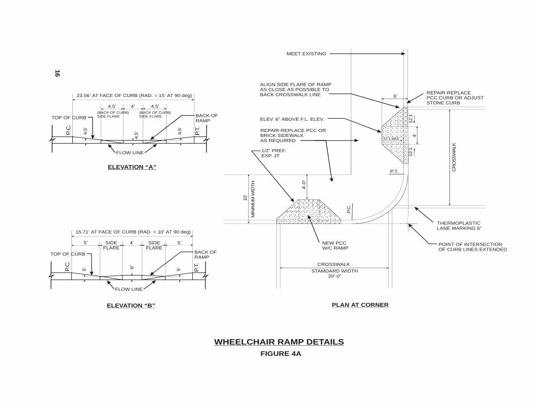
WHEELCHAIR RAMP DETAILS
FIGURE 4A
P.T.
10’
P.C
.
CR
OS
SW
ALK
STAMDARD WIDTH20’-0”
1/2” PREF.EXP. JT
REPAIR-REPLACE PCC ORBRICK SIDEWALK AS REQUIRED
ELEV. 6” ABOVE F.L. ELEV.
MEET EXISTING
REPAIR-REPLACEPCC CURB OR ADJUSTSTONE CURB
NEW PCCW/C RAMP
THERMOPLASTIC LANE MARKING 6”
12:1
12:1
6’
4’
PLAN AT CORNER
ELEVATION “A”
23.56’ AT FACE OF CURB (RAD. = 15’ AT 90 deg)
P.T.
P.C
.
4.5’ 4’ 4.5’
4.5
’
4.5
’4.5
’
BACK OFRAMP
TOP OF CURB
FLOW LINE
(BACK OF CURB)SIDE FLARE
(BACK OF CURB)SIDE FLARE
15.71’ AT FACE OF CURB (RAD. = 10’ AT 90 deg)
P.T.
P.C
.
5’ 4’ 5’
5’6”
5’
BACK OFRAMP
TOP OF CURB
FLOW LINE
ELEVATION “B”
SIDEFLARE
SIDEFLARE
16
MIN
IMU
M W
IDTH
POINT OF INTERSECTIONOF CURB LINES EXTENDED
ALIGN SIDE FLARE OF RAMP AS CLOSE AS POSSIBLE TO BACK CROSSWALK LINE
4’-0”
CROSSWALK
12:1 MAX
½”
SLOPE OF GUTTER:LOW SIDE - 1” PER FOOT TOWARD CURBHIGH SIDE- 5/8” PER FOOT AWAY FROM CURB
HALF BRICK
8” x 12” GRANITE CURBS WITH BRICK GUTTER
(NOT TO SCALE)
FIGURE 5
1.CONDITIONS BACK OF CURB VARY AS SHOWN ON PLANS.
2. P.C.C. (Dry Mix) SHALL BE PER SPCIFICATIONS ANDfc =2,500 PSI MIN.3. MINIMUM DEPTH TO CONCAVE SURFACE ON ROUGH FINISHSHALL BE 10”.
4. SEE FIGURE 6 FOR PATTERS FOR BRICK GUTTER.
NOTE:
2”
10”
12
”- 1
4”
7”
4”
12”+/-8”6”
7-1/2” X 3-1/2” X 3-1/2” BRICK
7”
4”
1/2” DOWEL
MORTAR CUSHION
JOINT OPTIONALP.C. CONC.(DRY MIX)
ROUGH FINISH +/- 1-1/2”
ASPHALT SUFACE
PCC BASE
1/2”
17
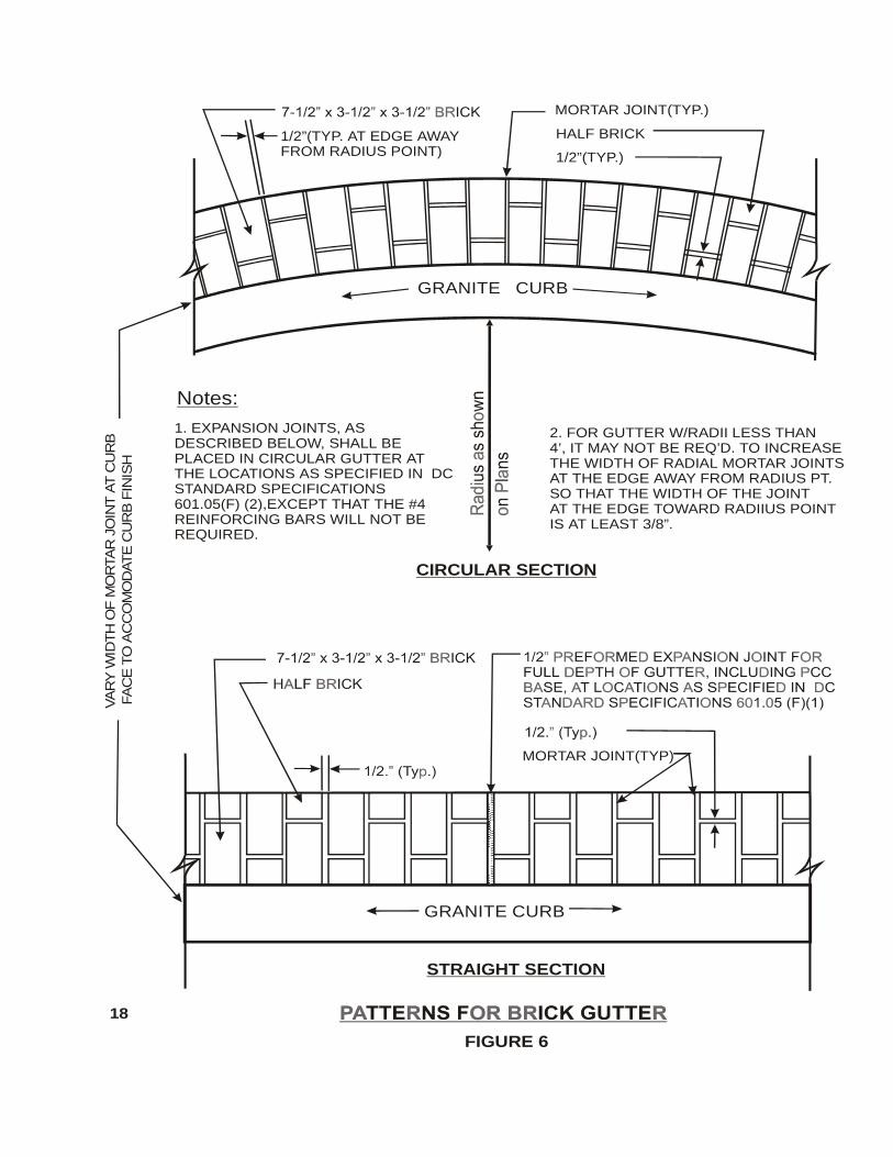
CIRCULAR SECTION
Notes:
1. EXPANSION JOINTS, AS DESCRIBED BELOW, SHALL BE PLACED IN CIRCULAR GUTTER ATTHE LOCATIONS AS SPECIFIED IN DCSTANDARD SPECIFICATIONS601.05(F) (2),EXCEPT THAT THE #4REINFORCING BARS WILL NOT BEREQUIRED.
2. FOR GUTTER W/RADII LESS THAN4’, IT MAY NOT BE REQ’D. TO INCREASETHE WIDTH OF RADIAL MORTAR JOINTSAT THE EDGE AWAY FROM RADIUS PT.SO THAT THE WIDTH OF THE JOINTAT THE EDGE TOWARD RADIIUS POINTIS AT LEAST 3/8”.
STRAIGHT SECTION
GRANITE CURB
MORTAR JOINT(TYP)
VA
RY
WID
TH
OF
MO
RTA
R J
OIN
T A
T C
UR
B F
AC
E T
O A
CC
OM
OD
ATE
CU
RB
FIN
ISH
FIGURE 6
1/2”(TYP. AT EDGE AWAYFROM RADIUS POINT)
HALF BRICK
MORTAR JOINT(TYP.)
GRANITE CURB
1/2”(TYP.)
18
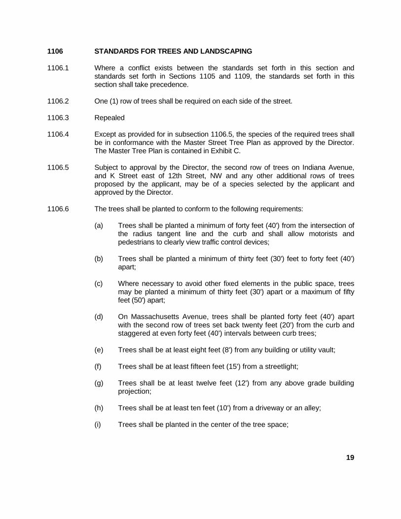
1106 STANDARDS FOR TREES AND LANDSCAPING
1106.1 Where a conflict exists between the standards set forth in this section andstandards set forth in Sections 1105 and 1109, the standards set forth in thissection shall take precedence.
1106.2 One (1) row of trees shall be required on each side of the street.
1106.3 Repealed
1106.4 Except as provided for in subsection 1106.5, the species of the required trees shallbe in conformance with the Master Street Tree Plan as approved by the Director.The Master Tree Plan is contained in Exhibit C.
1106.5 Subject to approval by the Director, the second row of trees on Indiana Avenue,and K Street east of 12th Street, NW and any other additional rows of treesproposed by the applicant, may be of a species selected by the applicant andapproved by the Director.
1106.6 The trees shall be planted to conform to the following requirements:
(a) Trees shall be planted a minimum of forty feet (40') from the intersection ofthe radius tangent line and the curb and shall allow motorists andpedestrians to clearly view traffic control devices;
(b) Trees shall be planted a minimum of thirty feet (30') feet to forty feet (40’)apart;
(c) Where necessary to avoid other fixed elements in the public space, treesmay be planted a minimum of thirty feet (30') apart or a maximum of fiftyfeet (50') apart;
(d) On Massachusetts Avenue, trees shall be planted forty feet (40') apartwith the second row of trees set back twenty feet (20') from the curb andstaggered at even forty feet (40') intervals between curb trees;
(e) Trees shall be at least eight feet (8') from any building or utility vault;
(f) Trees shall be at least fifteen feet (15') from a streetlight;
(g) Trees shall be at least twelve feet (12') from any above grade buildingprojection;
(h) Trees shall be at least ten feet (10') from a driveway or an alley;
(i) Trees shall be planted in the center of the tree space;
19
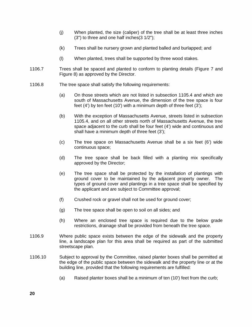
(j) When planted, the size (caliper) of the tree shall be at least three inches(3") to three and one half inches(3 1/2");
(k) Trees shall be nursery grown and planted balled and burlapped; and
(l) When planted, trees shall be supported by three wood stakes.
1106.7 Trees shall be spaced and planted to conform to planting details (Figure 7 andFigure 8) as approved by the Director.
1106.8 The tree space shall satisfy the following requirements:
(a) On those streets which are not listed in subsection 1105.4 and which aresouth of Massachusetts Avenue, the dimension of the tree space is fourfeet (4’) by ten feet (10') with a minimum depth of three feet (3’);
(b) With the exception of Massachusetts Avenue, streets listed in subsection1105.4, and on all other streets north of Massachusetts Avenue, the treespace adjacent to the curb shall be four feet (4’) wide and continuous andshall have a minimum depth of three feet (3’);
(c) The tree space on Massachusetts Avenue shall be a six feet (6’) widecontinuous space;
(d) The tree space shall be back filled with a planting mix specificallyapproved by the Director;
(e) The tree space shall be protected by the installation of plantings withground cover to be maintained by the adjacent property owner. Thetypes of ground cover and plantings in a tree space shall be specified bythe applicant and are subject to Committee approval;
(f) Crushed rock or gravel shall not be used for ground cover;
(g) The tree space shall be open to soil on all sides; and
(h) Where an enclosed tree space is required due to the below graderestrictions, drainage shall be provided from beneath the tree space.
1106.9 Where public space exists between the edge of the sidewalk and the propertyline, a landscape plan for this area shall be required as part of the submittedstreetscape plan.
1106.10 Subject to approval by the Committee, raised planter boxes shall be permitted atthe edge of the public space between the sidewalk and the property line or at thebuilding line, provided that the following requirements are fulfilled:
(a) Raised planter boxes shall be a minimum of ten (10') feet from the curb;
20
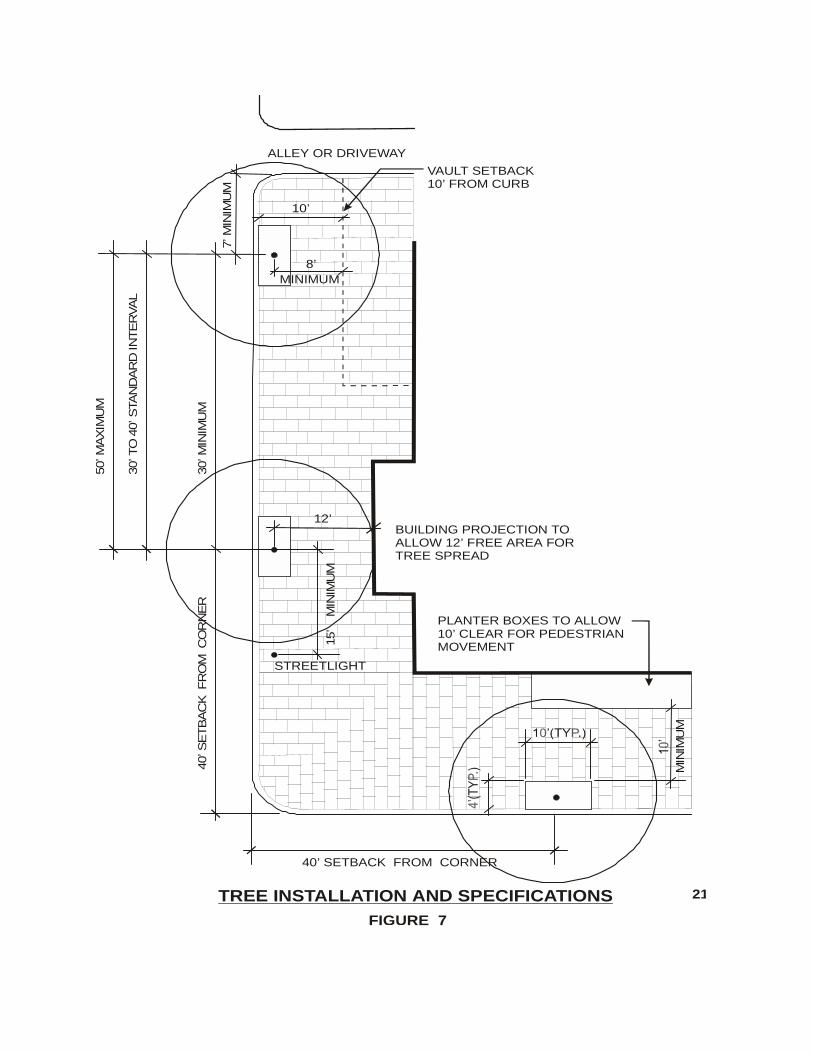
PLANTER BOXES TO ALLOW10’ CLEAR FOR PEDESTRIANMOVEMENT
21
MIN
IMU
M
BUILDING PROJECTION TO ALLOW 12’ FREE AREA FOR TREE SPREAD
15’
M
INIM
UM
7’ M
INIM
UM
10’
VAULT SETBACK 10’ FROM CURB
50’ M
AX
IMU
M
30’ T
O 4
0’ S
TAN
DA
RD
IN
TE
RVA
L
30’ M
INIM
UM
40’ SETBACK FROM CORNER
40’ S
ETB
AC
K F
RO
M C
OR
NE
R
FIGURE 7
TREE INSTALLATION AND SPECIFICATIONS
MINIMUM8’
STREETLIGHT
12’
ALLEY OR DRIVEWAY
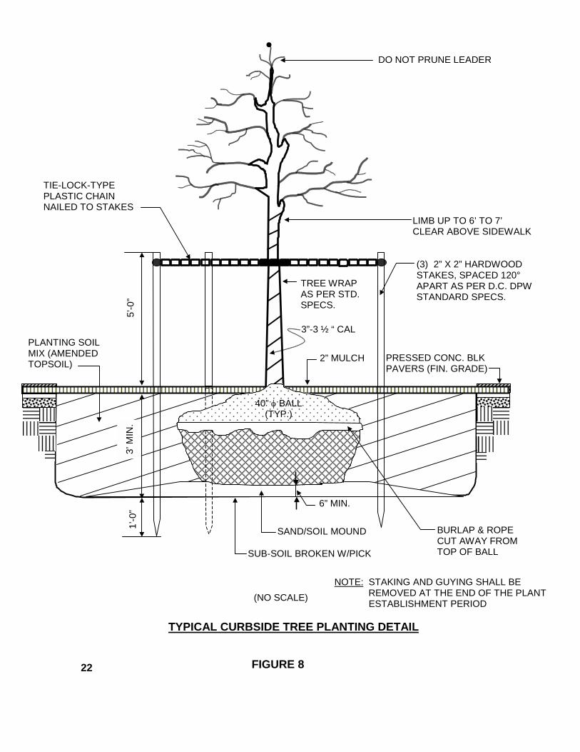
6” MIN.
PRESSED CONC. BLKPAVERS (FIN. GRADE)
(3) 2” X 2” HARDWOODSTAKES, SPACED 120° APART AS PER D.C. DPWSTANDARD SPECS.
NOTE: STAKING AND GUYING SHALL BEREMOVED AT THE END OF THE PLANT
ESTABLISHMENT PERIOD
LIMB UP TO 6’ TO 7’CLEAR ABOVE SIDEWALK
DO NOT PRUNE LEADER
2” MULCH
3”-3 ½ “ CAL
TIE-LOCK-TYPEPLASTIC CHAINNAILED TO STAKES
PLANTING SOILMIX (AMENDEDTOPSOIL)
BURLAP & ROPECUT AWAY FROMTOP OF BALL
TREE WRAPAS PER STD.SPECS.
SUB-SOIL BROKEN W/PICK
SAND/SOIL MOUND
1’-0
”5’
-0”
TYPICAL CURBSIDE TREE PLANTING DETAIL
FIGURE 8
(NO SCALE)
3’ M
IN.
40” φ BALL(TYP.)
22
(b) Raised planter boxes shall be clear of other sidewalk streetscapeelements, including, but not limited to, trees and tree spaces, signs,meters and streetlight poles; and
(c) Where planter boxes are accessible to pedestrians, the planter boxesmay be designed to serve as seating.
1106.11 Installation of electrical service within the tree box shall be subject to theapproval of the committee. Electrical service shall be metered to the owner’sbuilding.
1107 TREE MAINTENANCE REQUIREMENTS
1107.1 Any person who installs a tree pursuant to this chapter shall guarantee the life ofthe tree for one (1) year and shall replace any tree that dies or becomesdiseased during the one (1) year period.
1107.2 The adjacent property owner shall water any tree in the public space.
1107.3 The adjacent property owner shall perform any needed maintenance of the treespace, including, but not limited to, cleaning, weeding, mulching, andreplacement of plantings, or ground cover.
1107.4 The adjacent property owner shall perform any needed general maintenancework on landscaped areas and planter boxes installed on public space.
1107.5 The adjacent property owner or the Department may perform any emergencymaintenance of a tree in the public space.
1108 STANDARDS FOR AMENITIES AND STREET FURNITURE
1108.1 Subject to approval by the Public Space Committee and with therecommendation of the Committee, benches, trash receptacles and other streetfurniture and amenities may be installed in the public space.
1108.2 Any person who installs benches and other street furniture, trash receptacles andother amenities in the public space pursuant to this chapter shall guarantee theirmaintenance and replacement for one (1) year.
1108.3 After the one (1) year period provided for in subsection 1108.2, the adjacentproperty owner shall be responsible for the maintenance and replacement of thestreet furniture and amenities.
1108.4 Maintenance and replacement schedules for the street furniture and amenitiesshall be determined by the Director.
23
1108.5 Benches placed in the public space shall meet the following criteria:
(a) Benches shall be wrought iron with wood slats;
(b) Benches shall have backs and be of a Victorian style design approved bythe Director;
(c) Benches shall be a maximum eight feet (8’) long. Benches six feet (6’) orlonger shall have a center arm rest;
(d) Benches shall either face the building and be placed 3 feet from the curb,or face the curb, and be placed 2 feet from face of building; and
(e) Benches shall be anchored to the paving.
1108.6 Benches shall be installed and maintained by the adjacent property owner.
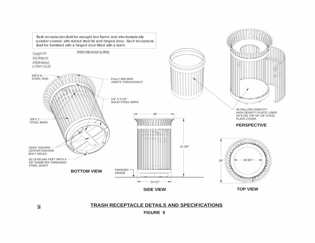
1108.7 Trash receptacles placed in the public space shall meet the following criteria:
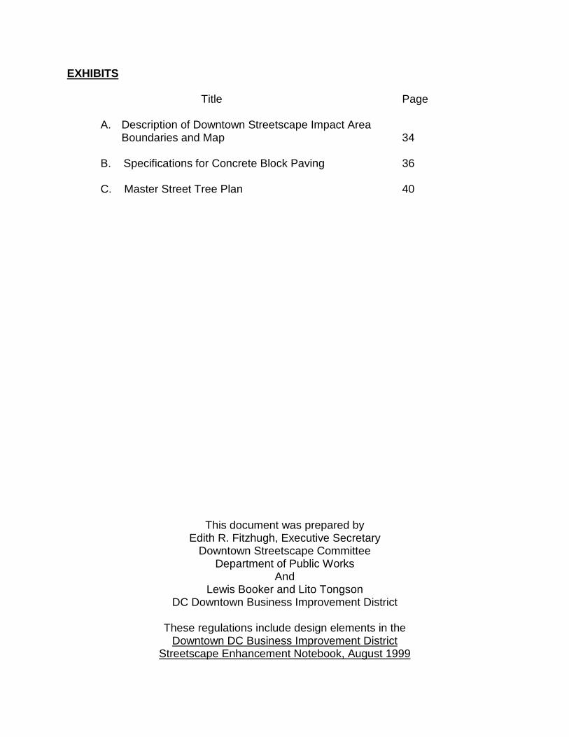
(a) Trash receptacles shall be wrought iron frame and electrostaticallypowder coated, with riveted steel lid and hinged door, as manufactured byVictor Stanley, Dunkirk, Maryland, (Figure 9) or equal as approved by theDirector;
(b) Each trash receptacles shall be 36-gallon capacity, 41-3/4 inches high,23-1/2 inches base diameter and 28 inches top diameter and furnishedwith unbreakable 36 gallon high-density plastic liner;
(c) Each trash receptacle shall be furnished with a spun steel lid with an 183/4 inch diameter opening. The steel lid must be riveted to the innerframe perimeter, so that it cannot be removed;
(d) Each trash receptacle shall be furnished with a base consisting of a three-point anchoring system with five (5) hard plastic coated adjustableleveling glides. A one-eighth (1/8") inch steel plate with three (3) 3/4 inchholes for anchoring must be welded to the base assembly;
(e) Each trash receptacle shall be furnished with a hinged steel door fittedwith a latch;
(f) Color of trash receptacle shall be black; and
(g) Installation of trash receptacles shall be per manufacturer’srecommendation, with District of Columbia government direction forplacement.
24
BOTTOM VIEW
FIGURE 9
Trash receptacles shall be wrought iron frame and electrostatically powder coated, with riveted steel lid and hinged door. Each receptacle shall be furnished with a hinged door fitted with a latch.
TRASH RECEPTACLE DETAILS AND SPECIFICATIONS25
PERSPECTIVE
36 GALLON CAPACITYHIGH DENSITY PLATIC LINERSITS ON TOP OF 1/8” STEELPLATE COVER
TOP VIEW
18-3/4”28”
SIDE VIEW
28”
41-3/4”
23-1/2”
FINISHED GRADE
FULLY WELDEDJOINTS THROUGHOUT
1/4” X 2-1/2”SOLID STEEL BARS
5/8”O.D.STEEL ROD
3/8”X 1”STEEL BARS
(3)3/4” SQUARECENTER ANCHORBOLT HOLES
(5) LEVELING FEET WITH A3/8” DIAMETER THREADED STEEL SHAFT
1108.8 The District shall install all trash receptacles within the boundaries of theBusiness Improvement District. All private trash receptacles in other areas shallbe installed by adjacent property owner.
1108.9 All trash receptacles shall be maintained and repaired by adjacent propertyowners. The District shall pick up from all trash receptacles on public spacewithin the Business Improvement District boundaries.
1108.10 Subject to approval by the Public Space Committee and with therecommendation of the Committee, an applicant may install public art in thepublic space between the sidewalk and the property line.
1108.11 Banners may be used-on streetlights within the Downtown Streetscape Areapursuant to public space regulations with the approval of the Committee.
1108.12 Location of bike racks in public space shall be coordinated with and approved byTraffic Safety Branch, Bureau of Traffic Services.
1108.13 Bike racks shall meet the following criteria:
(a) The bike rack shall be an inverted U type. The bike rack should supportthe frame of the bike at two locations; allow at least one wheel along theframe to be locked to the rack; and allow cyclist the option of using eitherthe popular U-lock or a cable with padlock;
(b) Bike racks shall be 2-3/8" O.D. (outside diameter), galvanized, schedule40 steel pipe, ASTM 53A, powder coated, gloss black, measuring 30"across and 36" high above grade;
(c) Bike rack shall have minimum 5ft. clearance from other amenities andstreet furniture;
(d) Bike rack shall be placed parallel to the curb and 3ft. from the face ofcurb;
(e) Bike rack shall be placed within the typical 26 feet distance from the endof the Metro Bus Stop Zone;
(f) Bike rack placement shall allow a minimum of ten (10) feet of clearancefor pedestrian flow; and
(g) Bike racks shall not be placed in an entrance or loading zone.
1108.14 Street furniture and amenities shall be located to provide twenty feet (20') on oneside of a tree box space to allow for the maneuvering of tree maintenanceequipment.
26
1109 STANDARDS FOR UNDERGROUND VAULTS
1109.1 All vaults shall be set back at least ten feet (10') from the curb, and, where two(2) rows of trees are proposed or required, the first level of the building vaultsshall be set back at least thirty feet (30') from the curb.
1109.2 Where the existing building vault is within ten feet (10') of the curb (or within thirtyfeet (30') of the curb where two (2) rows of trees are required or proposed), theapplicant shall be required to abandon and backfill the existing vault with asuitable material solely to the extent necessary for the planting of the treesrequired by Section 1106.
1109.3 Utility vaults shall not be within eight feet (8') of a tree location. Utility vaults shallconform to the applicable District of Columbia laws, rules, and regulations.
1109.4 PEPCO equipment serving new construction or substantial rehabilitation shall belocated in vaults or on pads on private property; except the Director may approvea different location for a utility vault, pad, or manhole when the followingconditions are satisfied:
(a) Locating PEPCO equipment in a vault or within or on the roof of a buildingor on a pad on private property is not feasible;
(b) The proposed location for the utility vault shall not be within or under themajor pedestrian movement areas;
(c) The manhole covers shall be solid and filled with a material the same asor compatible with the adjoining sidewalk;
(d) When proposed to be located in a driveway or a public alley, the utilityvaults with the solid filled covers shall be capable of withstanding theweight of commercial vehicles, and shall be located to avoid majorpedestrian movement areas; and
(e) When proposed to be located on the public space between the sidewalkand the property line, the utility vault may be located in this area when thefollowing conditions are fulfilled:
(1) The utility vault is incorporated into the landscape design;
(2) The utility vault does not interfere with the planting of requiredtrees; and
(3) The utility vault cover shall be solid and filled with a material thesame as or compatible with the adjoining sidewalk.
27
1109.5 Plans submitted for Committee review shall show the depth of cover overbuilding vault projections into public space. There shall be one foot (1') of soil fillbetween the top of the vault and the bottom of the sidewalk.
1109.6 Only existing grate covers on Metro utility vaults shall be allowed in public spacebetween the sidewalk and the property line.
1109.7 Utility vault covers shall be constructed to allow the standard paving material atgrade.
1109.8 When feasible and practical, existing vaults shall conform to the standard's setforth in this subsection.
1110 STANDARDS FOR STREET ACCESS
1110.1 The location of curb cuts and driveways shall be approved when the followingconditions are fulfilled:
(a) The land use, traffic and pedestrian patterns, and transit operation in thearea have been considered;
(b) Where feasible, access to loading and parking facilities shall be from analley;
(c) Where feasible, loading facilities shall be located below grade;
(d) On the following streets, curb cuts and driveways shall be approved onlyif the applicant demonstrates that there is no other means or method ofproviding vehicular access to the property:
(1) F Street, NW between 7th Street and 15th Street;
(2) G Street, NW between 7th Street and 15th Street;
(3) 7th Street, NW between Pennsylvania Avenue and MassachusettsAvenue;
(4) 8th Street, NW between Pennsylvania Avenue and MassachusettsAvenue;
(5) 10th Street, NW between Pennsylvania Avenue and H Street; and
(e) Circular driveways, building entrance driveways, porte cocheres, andlaybys shall not be permitted in the Downtown Streetscape Area, unlessapproved by the Director.
28
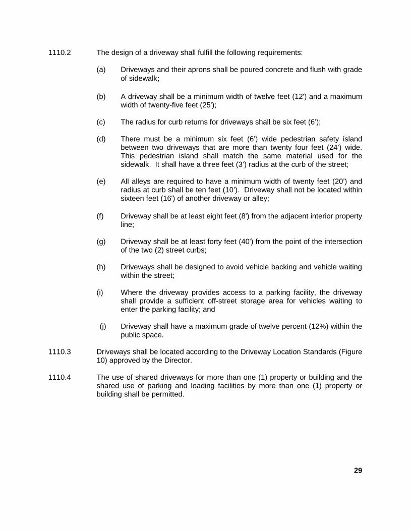
1110.2 The design of a driveway shall fulfill the following requirements:
(a) Driveways and their aprons shall be poured concrete and flush with gradeof sidewalk;
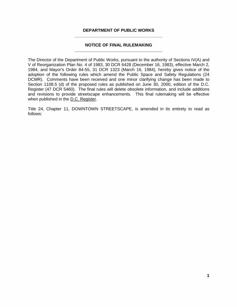
(b) A driveway shall be a minimum width of twelve feet (12') and a maximumwidth of twenty-five feet (25');
(c) The radius for curb returns for driveways shall be six feet (6’);
(d) There must be a minimum six feet (6’) wide pedestrian safety islandbetween two driveways that are more than twenty four feet (24’) wide.This pedestrian island shall match the same material used for thesidewalk. It shall have a three feet (3’) radius at the curb of the street;
(e) All alleys are required to have a minimum width of twenty feet (20’) andradius at curb shall be ten feet (10’). Driveway shall not be located withinsixteen feet (16') of another driveway or alley;
(f) Driveway shall be at least eight feet (8') from the adjacent interior propertyline;
(g) Driveway shall be at least forty feet (40') from the point of the intersectionof the two (2) street curbs;
(h) Driveways shall be designed to avoid vehicle backing and vehicle waitingwithin the street;
(i) Where the driveway provides access to a parking facility, the drivewayshall provide a sufficient off-street storage area for vehicles waiting toenter the parking facility; and
(j) Driveway shall have a maximum grade of twelve percent (12%) within thepublic space.
1110.3 Driveways shall be located according to the Driveway Location Standards (Figure10) approved by the Director.
1110.4 The use of shared driveways for more than one (1) property or building and theshared use of parking and loading facilities by more than one (1) property orbuilding shall be permitted.
29
25
’ MIN
.
6’ R
6’ R
6’ R
6’ R
15’
R M
IN.
15
’ R
MIN
.
20
’ MIN
.
PROPERTY LINE
POINT OF INTERSECTION
20’STANDARD
25
’ MIN
.
WHEEL CHAIR RAMPS SIDE FLARE MUST ALIGNWITH BACKEDGE OFCROSSWALK
PROPERTY LINE
6’ R
6’ R
6’ R
3’ R
3’ R
6’ R
10’ R
10’ R
FIGURE 10
DRIVEWAY LOCATION STANDARDS30
CROSSWALK
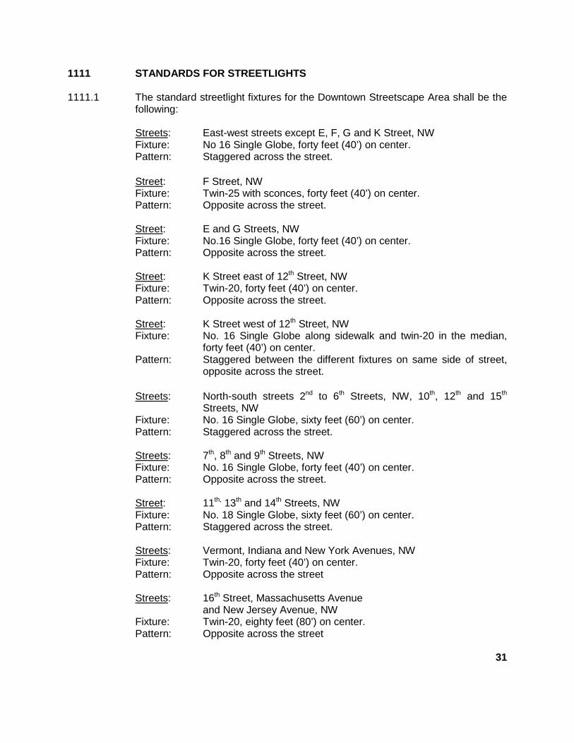
1111 STANDARDS FOR STREETLIGHTS
1111.1 The standard streetlight fixtures for the Downtown Streetscape Area shall be thefollowing:
Streets: East-west streets except E, F, G and K Street, NWFixture: No 16 Single Globe, forty feet (40’) on center.Pattern: Staggered across the street.
Street: F Street, NWFixture: Twin-25 with sconces, forty feet (40’) on center.Pattern: Opposite across the street.
Street: E and G Streets, NWFixture: No.16 Single Globe, forty feet (40’) on center.Pattern: Opposite across the street.
Street: K Street east of 12th Street, NWFixture: Twin-20, forty feet (40’) on center.Pattern: Opposite across the street.
Street: K Street west of 12th Street, NWFixture: No. 16 Single Globe along sidewalk and twin-20 in the median,
forty feet (40’) on center.Pattern: Staggered between the different fixtures on same side of street,
opposite across the street.
Streets: North-south streets 2nd to 6th Streets, NW, 10th, 12th and 15th
Streets, NWFixture: No. 16 Single Globe, sixty feet (60’) on center.Pattern: Staggered across the street.
Streets: 7th, 8th and 9th Streets, NWFixture: No. 16 Single Globe, forty feet (40’) on center.Pattern: Opposite across the street.
Street: 11th, 13th and 14th Streets, NWFixture: No. 18 Single Globe, sixty feet (60’) on center.Pattern: Staggered across the street.
Streets: Vermont, Indiana and New York Avenues, NWFixture: Twin-20, forty feet (40’) on center.Pattern: Opposite across the street
Streets: 16th Street, Massachusetts Avenueand New Jersey Avenue, NW
Fixture: Twin-20, eighty feet (80’) on center.Pattern: Opposite across the street
31
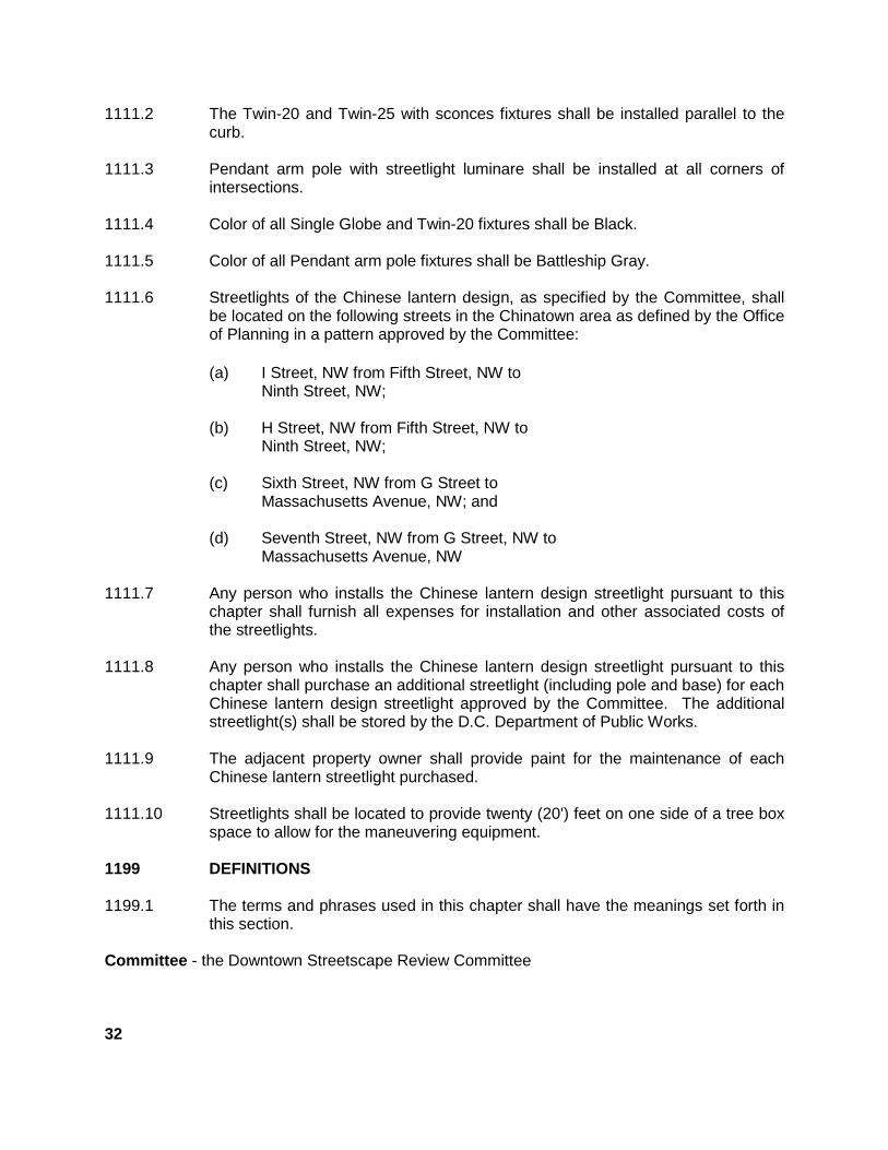
1111.2 The Twin-20 and Twin-25 with sconces fixtures shall be installed parallel to thecurb.
1111.3 Pendant arm pole with streetlight luminare shall be installed at all corners ofintersections.
1111.4 Color of all Single Globe and Twin-20 fixtures shall be Black.
1111.5 Color of all Pendant arm pole fixtures shall be Battleship Gray.
1111.6 Streetlights of the Chinese lantern design, as specified by the Committee, shallbe located on the following streets in the Chinatown area as defined by the Officeof Planning in a pattern approved by the Committee:
(a) I Street, NW from Fifth Street, NW toNinth Street, NW;
(b) H Street, NW from Fifth Street, NW toNinth Street, NW;
(c) Sixth Street, NW from G Street toMassachusetts Avenue, NW; and
(d) Seventh Street, NW from G Street, NW toMassachusetts Avenue, NW
1111.7 Any person who installs the Chinese lantern design streetlight pursuant to thischapter shall furnish all expenses for installation and other associated costs ofthe streetlights.
1111.8 Any person who installs the Chinese lantern design streetlight pursuant to thischapter shall purchase an additional streetlight (including pole and base) for eachChinese lantern design streetlight approved by the Committee. The additionalstreetlight(s) shall be stored by the D.C. Department of Public Works.
1111.9 The adjacent property owner shall provide paint for the maintenance of eachChinese lantern streetlight purchased.
1111.10 Streetlights shall be located to provide twenty (20') feet on one side of a tree boxspace to allow for the maneuvering equipment.
1199 DEFINITIONS
1199.1 The terms and phrases used in this chapter shall have the meanings set forth inthis section.
Committee - the Downtown Streetscape Review Committee
32
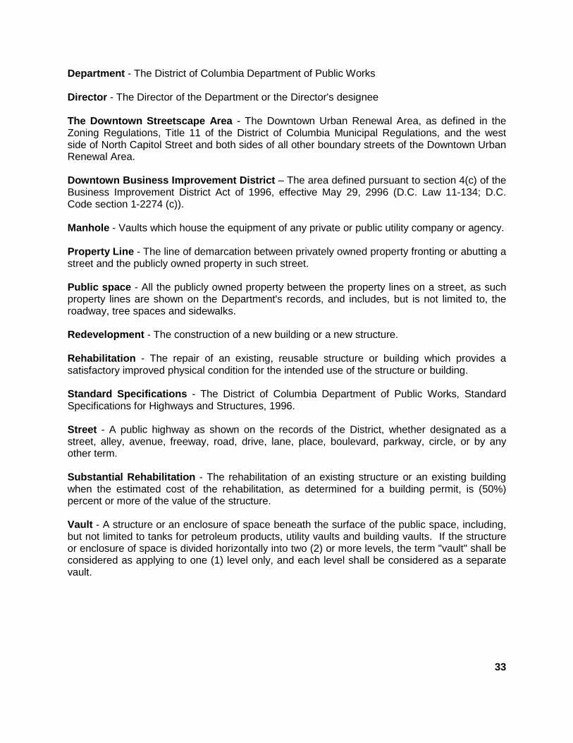
Department - The District of Columbia Department of Public Works
Director - The Director of the Department or the Director's designee
The Downtown Streetscape Area - The Downtown Urban Renewal Area, as defined in theZoning Regulations, Title 11 of the District of Columbia Municipal Regulations, and the westside of North Capitol Street and both sides of all other boundary streets of the Downtown UrbanRenewal Area.
Downtown Business Improvement District – The area defined pursuant to section 4(c) of theBusiness Improvement District Act of 1996, effective May 29, 2996 (D.C. Law 11-134; D.C.Code section 1-2274 (c)).
Manhole - Vaults which house the equipment of any private or public utility company or agency.
Property Line - The line of demarcation between privately owned property fronting or abutting astreet and the publicly owned property in such street.
Public space - All the publicly owned property between the property lines on a street, as suchproperty lines are shown on the Department's records, and includes, but is not limited to, theroadway, tree spaces and sidewalks.
Redevelopment - The construction of a new building or a new structure.
Rehabilitation - The repair of an existing, reusable structure or building which provides asatisfactory improved physical condition for the intended use of the structure or building.
Standard Specifications - The District of Columbia Department of Public Works, StandardSpecifications for Highways and Structures, 1996.
Street - A public highway as shown on the records of the District, whether designated as astreet, alley, avenue, freeway, road, drive, lane, place, boulevard, parkway, circle, or by anyother term.
Substantial Rehabilitation - The rehabilitation of an existing structure or an existing buildingwhen the estimated cost of the rehabilitation, as determined for a building permit, is (50%)percent or more of the value of the structure.
Vault - A structure or an enclosure of space beneath the surface of the public space, including,but not limited to tanks for petroleum products, utility vaults and building vaults. If the structureor enclosure of space is divided horizontally into two (2) or more levels, the term "vault" shall beconsidered as applying to one (1) level only, and each level shall be considered as a separatevault.
33
EXHIBIT A
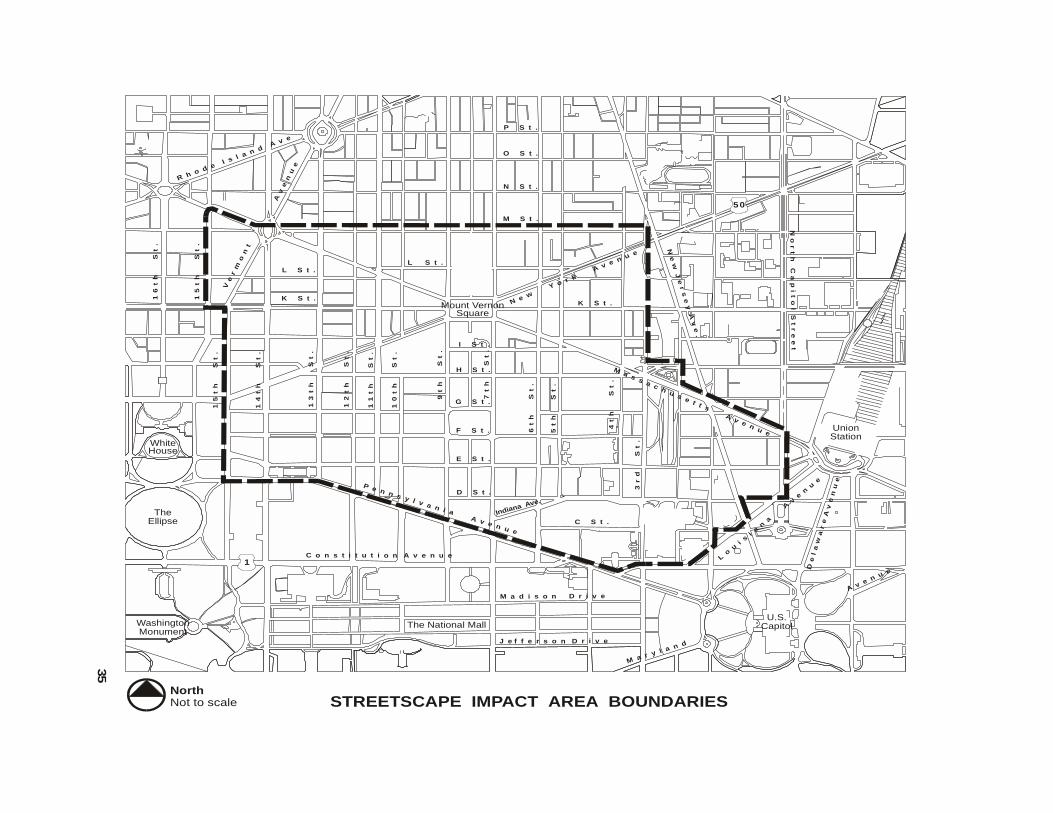
IMPACT AREA BOUNDARIES
The boundaries of the Downtown Streetscape Area are approximately the same as thedesignated street boundaries for the Downtown Urban Renewal Area. The west side of NorthCapitol Street, the north side of Pennsylvania Avenue and both sides of all other boundarystreets are subject to the Streetscape Regulations. Further, when a project is on a corner lot,one side of which is within the boundaries subject to the Streetscape Regulations, the other sideof the project also will be subject to these guidelines.
Description of Project Area
The boundaries of the Downtown Urban Renewal Area are described in the Downtown UrbanRenewal Plan as follows: Beginning at the northwest corner of the intersection of FifteenthStreet, NW and Massachusetts Avenue, NW, thence along the north line of MassachusettsAvenue, NW to the northwest corner of Fourteenth Street, NW and Thomas Circle, thence alongthe north line of Thomas Circle to its intersection with the south line of "M" Street, NW to itsintersection with the west line of Third Street, NW, thence along the west line of Third Street,NW to its intersection with the south line of "H" Street, NW, thence along the south line of "H"Street, NW, to its intersection with the west line of Second Street, NW, thence along the westline of Second Street, NW to its intersection with the south line of Massachusetts Avenue, NW,thence along the south line of Massachusetts Avenue, NW to its intersection with the west lineof North Capitol Street, thence along the west line of North Capitol Street to its intersection withthe north line of Louisiana Avenue, NW, thence along the north line of Louisiana Avenue, NW toits intersection with the north line of "D" NW, thence along the north line of "D" Street N.W, to itsintersection with the west line of New Jersey Avenue, NW, thence along the west line of NewJersey Avenue, NW, to its intersection with the north line of Louisiana Avenue, NW, thencealong the north line of Louisiana Avenue, NW to its intersection with the north line of "C" Street,NW thence along the north line of "C" Street, NW, to its intersection with the west line of FirstStreet, NW, thence along the west line of First Street, NW to its intersection with the north line ofLouisiana Avenue, NW, thence along the north line of Louisiana Avenue, NW to the intersectionwith the north line of Constitution Avenue, NW, thence along the north line of ConstitutionAvenue, NW, to its intersection with the east line of Second Street, NW, thence along the eastline of Second Street, NW, to its intersection with the south line of Constitution Avenue, NW,thence along the south line of Constitution Avenue, NW to its intersection with the north line ofPennsylvania Avenue, NW, thence along the north line of Pennsylvania Avenue, NW to itsintersection with the south line of "E" Street at Thirteenth Street NW, thence along the south lineof "E" Street NW to its intersection with the west line of Fifteenth Street NW, thence along thewest line of Fifteenth Street, NW to its intersection with the south line of "K" Street, NW, thencewest along the south line of "K" Street, NW to its intersection with the west line of FifteenthStreet NW, thence north along the west line of Fifteenth Street, NW, to the point of beginning.
34
TheEllipse
WhiteHouse
U.S.Capitol
UnionStation
The National MallWashingtonMonument
FutureConvention
Center
P e n n s y l v a n i a A v e n u e
N e w Y
o r k A
v e n u e
Ma s s a c h u s e t t s A v e n u e
Lo
ui
si
an
a
A
ve
nu
e
Ve
rm
on
t
Av
en
ue
K S t .
I S t .
H S t .
G S t .
F S t .
E S t .
D S t .
14
th
St
.
13
th
St
.
12
th
St
.
11
th
St
.
10
th
S
t.
K S t .
L S t .L S t .
M S t .
9t
h
S
t.
7t
h
S
t.
6t
h
S
t.
5t
h
St
.
4t
h
S
t.
3r
d
S
t.
C S t .
C o n s t i t u t i o n A v e n u e
Indiana Ave.
15
th
St
.
15
th
St
.
16
th
St
.
NorthNot to scale STREETSCAPE IMPACT AREA BOUNDARIES
N S t .
O S t .
P S t .
R h o d e Is l a n d A
v e
Mount VernonSquare
50
1
M a d i s o n D r i v e
J e f f e r s o n D r i v e
M a r y l a n d
Av e n u e
De
la
wa
re
Av
en
ue
No
rt
h C
ap
it
ol S
tr
ee
t
Ne
w J
er
se
y Av
e.
35
EXHIBIT B
SPECIFICATIONS FORPRESSED CONCRETE BLOCK PAVING ON PCC BASE
I. GENERAL
Pressed concrete block paving shall be constructed in those areas as shown onthe plans and/or as directed, and shall consist of hydraulically pressed, modular,precast concrete block pavers placed on a sand-cement bed of PCC base. Theexact pattern, paver size, finish, quality, and construction details shall be asspecified herein and as shown on the plans.
Pressed concrete block pavers shall be manufactured by Hastings PavementCompany, 410 Lakeville Road, Lake Success, N.Y., 11040; Hanover PrestPaving Company, R.D. #4, Bender Road, Hanover, Pa 17331; or approvedequal.
Before work is begun, the Contractor shall present a sample paver to the PublicSpace Maintenance Administration for approval by the D.C. Department of PublicWorks.
II. MATERIALS
Materials used shall meet the following requirements:
A. Portland Cement - Section 817.01 of the Standard SpecificationsB. Sand - Section 803.01 of the Standard Specifications for sand-cement
bed.C. Sand - Section 803.01 of the Standard Specifications for joints.D. Water - Section 821.01 of the Standard Specifications.E. Pressed Concrete Block Pavers:
1. Module size for sidewalk paving shall be24"x 36"x 2" (nominal) or metric equivalent. Pavers shall have atolerance of +/- 1/16" in length and width and +/- 1/8" in thickness.All top edges of pavers shall have a 3/16" bevel.
2. Color shall be charcoal gray.
3. Finish shall be non-slip, natural or stipple, finish. Large, rough,exposed aggregate surfaces are not acceptable.
4. Physical properties of pressed concrete pavers for the sidewalkshall meet the following requirements:
36
a. Average compressive strength of four (4) 2" x 2" x 2"cubes or 2" diameter cylindrical cores obtained from twopavers per lot shall be 5000 psi minimum as tested byAASHTO T 32.
b. Maximum 24-hour cold water absorption shall be less thanfive percent (5%) tested in accordance with AASHTO T 32,Section 7, except 4 specimens will be used. After 50cycles of freezing and thawing in accordance withAASHTO T 32 or a 3 day application of three percent (3%)sodium chloride solution, 1/2 inch deep, weight loss shallbe less than three percent (3%) and no visual signs ofdeterioration.
F. Preformed Expansion Joint - Section 807.01 of the StandardSpecifications
G. Masonry Cement - The manufacturer shall certify that masonry cementmeets the requirements of AASHTO M 150. Certification shall consist ofa copy of the manufacturer's test results and statement by themanufacturer that the material presented by a lot or batch number hasbeen sampled and tested, meeting the requirements of this Specification.The statement shall include the date of testing and shall be signed by anauthorized agent of the manufacturer.
H. Sealant - Cold-pour sealant shall be a non-sag, elastomeric sealantmeeting Federal Specification TT-227E, Type II. Color of sealant shall benatural gray.
I. Epoxy Mortar - Section 821.10 of the Standard Specifications
III. CONSTRUCTION METHODS
A. Construction of pressed concrete block paving for sidewalk shall meet thefollowing requirements:
1. Aggregate Base Course - New Aggregate Base Course, asrequired, shall be brought to within 6 3/4 inches of final grade.Soils base used shall meet the requirements of Section 209 of theStandard Specifications.
2. PCC Base - Where pressed concrete block pavers are to beplaced on PCC Base, that base shall be prepared as follows:
A four (4") inch PCC base shall be constructed on aggregate basecourse as per Section 209 of the Standard Specifications. PCCused shall be as per 817 of the Standard Specifications.
37
Broom or machine finishing, scoring, carbon powder, and jointsealer are not required.
Joint sealant shall be used in horizontal joints back of curbs andalong building lines, and shall meet the requirements of Section807.02 of the Standard Specifications.
3. Sand - Cement Bed - Sand-cement bedding course shall consistof 1 part cement and 2 parts sand by volume, mixed dry until themass is of uniform color. Mixing may be done in an approvedbatch mixer or by hand on a clean, tight surface. Once thoroughlymixed, the mass shall be lightly moistened with water.
The bedding course shall be placed and shaped upon the PCCbase so that its finished depth shall be 3/4 inch. The beddingshall be shaped to a true- surface, paralleled with surface offinished paving, by means of a template or striking board. Thebed shall then be struck off until proper alignment is secured. Thearea of bedding placed in any workday shall be scheduled so thatno bedding course remains at the end of the day without a pavercourse. After final shaping, the bedding course shall not bedisturbed prior to the laying of pavers.
4. Vaults - PEPCO will remove the old removable-type steel vaultcovers over transformer vaults and will furnish and install newsteel pan vault covers. On the new pan covers, the contractorshall inlay pressed concrete block pavers on an epoxy-mortar bed.Level of pavers shall be flush with surrounding grade. Joints shallmatch that of the adjacent sidewalk pavers, as much aspracticable. Small pavers, less than six (6") inches in length, willbe allowed for use only in the paving of the PEPCO vault covers.
PEPCO shall be notified at least three weeks in advance beforepaving work over the vault covers will begin.
Where building vaults are encountered below grade, the pressedconcrete block pavers shall be laid on sand-cement leveling bedinstalled in two lifts. The first lift shall be laid and compacted as aleveling course. The second lift shall be 3/4 inch depth andtreated as a setting bed for pressed concrete block pavers.
Expansion joint material, 1/2 inch wide, shall extend from thevertical face of the underground vaults up through the sand-cement beds to within approximately 1/2 of the surface of thePressed Concrete Block paving. Joints shall be sealed withsealant.
38
5. Laying Pavers - Pavers shall be laid in successive straight coursesstarting perpendicular to the curb and working toward the buildingline. The non-slip finished face of the paver will be placed up.
The surface edge of one paver shall be level with the nextadjacent pavers so that no voids, rocking motions, or trippinghazards are encountered. Edge to edge arris shall not exceed1/16 inch.
Before the pressed concrete block pavers are installed in place,the backs of the pavers shall be moistened with water. Paversshall be cut to fit around catch basins, wheelchair/bicycle ramps,and light standard bases. Where cutting is required, it shall bedone with a high sped masonry saw producing clean, sharpedges.
Square-poured concrete collars of color and treatment similar tothat of pressed concrete block pavers, shall be constructedaround flagpole bases, manholes, and other small sidewalkinterruption, or as directed by the Engineer.
The contractor shall procure from the paver suppliers, bags of thesame sand, cement, and aggregate used in the manufacture ofthe pressed concrete paving blocks for use in the poured concreteareas. The poured concrete shall be scarred to match theadjacent pavers.
Where irregularities of the line and grade exist at the building line,a shoreline of smaller pavers, poured concrete, or other treatmentmay be acceptable, upon approval by the engineer. In no casewill pavers less than 6 inches in length be used.
6. Joint - Joints shall be 1/4 inch maximum between pavers. Edgesof pavers shall be bevelled to 3/16 inch maximum. Combinedwidth across beveled joint shall be 5/8 inch maximum.
Immediately after the installation of the pressed concrete blockpavers, the joints shall be swept with a dry sand-cement mix, 2:1by volume. The surface shall then be swept and inspected.Joints shall be wetted with a fine spray after the sand-cement isworked on.
7. Imperfect Pavers - Any imperfect pavers, as determined by theengineer, shall be removed and replaced.
39
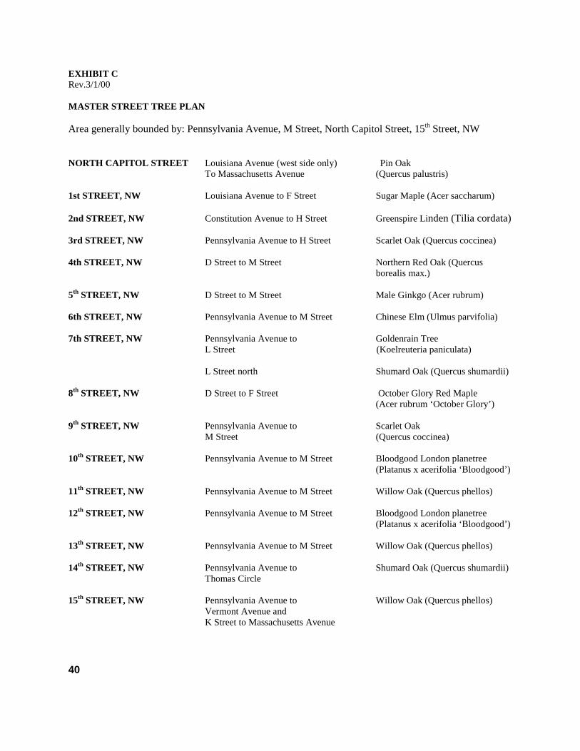
EXHIBIT CRev.3/1/00
MASTER STREET TREE PLAN
Area generally bounded by: Pennsylvania Avenue, M Street, North Capitol Street, 15th Street, NW
NORTH CAPITOL STREET Louisiana Avenue (west side only) Pin OakTo Massachusetts Avenue (Quercus palustris)
1st STREET, NW Louisiana Avenue to F Street Sugar Maple (Acer saccharum)
2nd STREET, NW Constitution Avenue to H Street Greenspire Linden (Tilia cordata)
3rd STREET, NW Pennsylvania Avenue to H Street Scarlet Oak (Quercus coccinea)
4th STREET, NW D Street to M Street Northern Red Oak (Quercus borealis max.)
5th STREET, NW D Street to M Street Male Ginkgo (Acer rubrum)
6th STREET, NW Pennsylvania Avenue to M Street Chinese Elm (Ulmus parvifolia)
7th STREET, NW Pennsylvania Avenue to Goldenrain TreeL Street (Koelreuteria paniculata)
L Street north Shumard Oak (Quercus shumardii)
8th STREET, NW D Street to F Street October Glory Red Maple(Acer rubrum ‘October Glory’)
9th STREET, NW Pennsylvania Avenue to Scarlet OakM Street (Quercus coccinea)
10th STREET, NW Pennsylvania Avenue to M Street Bloodgood London planetree(Platanus x acerifolia ‘Bloodgood’)
11th STREET, NW Pennsylvania Avenue to M Street Willow Oak (Quercus phellos)
12th STREET, NW Pennsylvania Avenue to M Street Bloodgood London planetree(Platanus x acerifolia ‘Bloodgood’)
13th STREET, NW Pennsylvania Avenue to M Street Willow Oak (Quercus phellos)
14th STREET, NW Pennsylvania Avenue to Shumard Oak (Quercus shumardii)Thomas Circle
15th STREET, NW Pennsylvania Avenue to Willow Oak (Quercus phellos)Vermont Avenue andK Street to Massachusetts Avenue
40
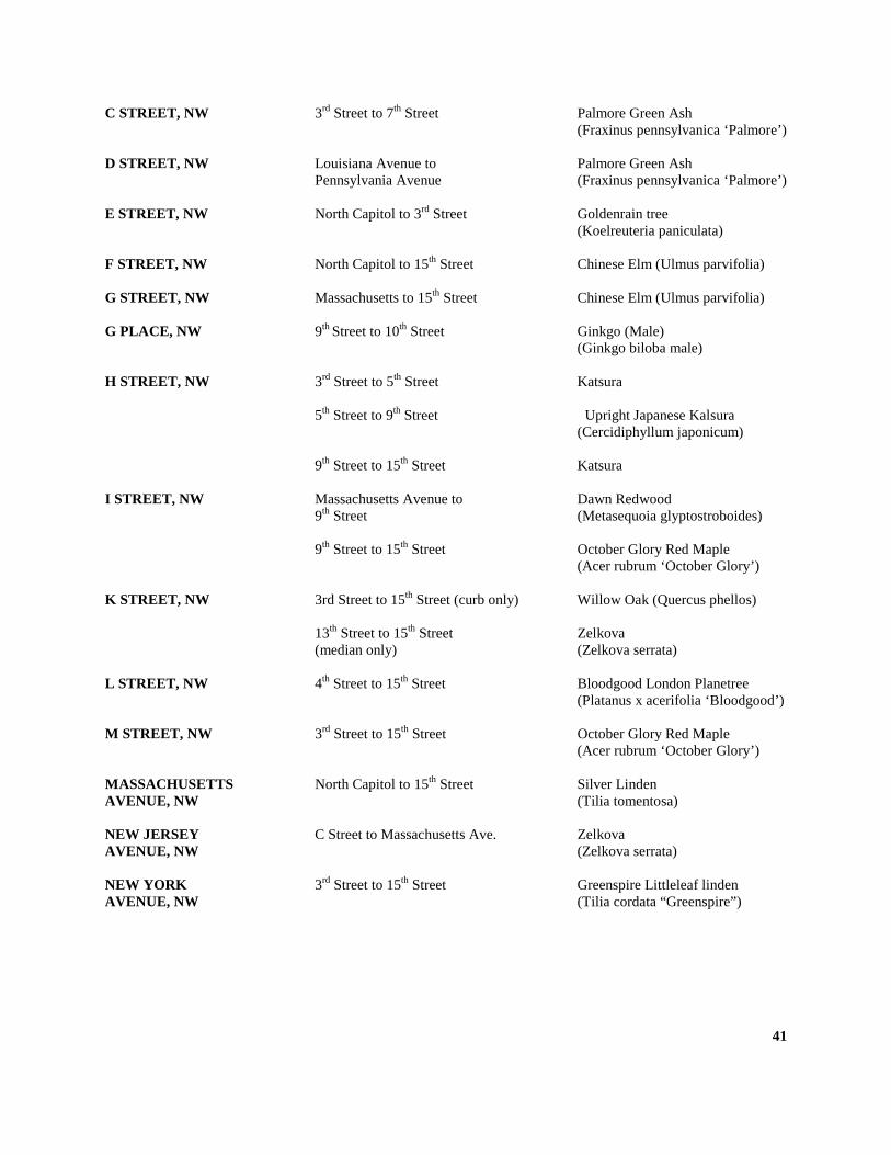
C STREET, NW 3rd Street to 7th Street Palmore Green Ash (Fraxinus pennsylvanica ‘Palmore’)
D STREET, NW Louisiana Avenue to Palmore Green AshPennsylvania Avenue (Fraxinus pennsylvanica ‘Palmore’)
E STREET, NW North Capitol to 3rd Street Goldenrain tree(Koelreuteria paniculata)
F STREET, NW North Capitol to 15th Street Chinese Elm (Ulmus parvifolia)
G STREET, NW Massachusetts to 15th Street Chinese Elm (Ulmus parvifolia)
G PLACE, NW 9th Street to 10th Street Ginkgo (Male)(Ginkgo biloba male)
H STREET, NW 3rd Street to 5th Street Katsura
5th Street to 9th Street Upright Japanese Kalsura(Cercidiphyllum japonicum)
9th Street to 15th Street Katsura
I STREET, NW Massachusetts Avenue to Dawn Redwood9th Street (Metasequoia glyptostroboides)
9th Street to 15th Street October Glory Red Maple(Acer rubrum ‘October Glory’)
K STREET, NW 3rd Street to 15th Street (curb only) Willow Oak (Quercus phellos)
13th Street to 15th Street Zelkova(median only) (Zelkova serrata)
L STREET, NW 4th Street to 15th Street Bloodgood London Planetree(Platanus x acerifolia ‘Bloodgood’)
M STREET, NW 3rd Street to 15th Street October Glory Red Maple(Acer rubrum ‘October Glory’)
MASSACHUSETTS North Capitol to 15th Street Silver LindenAVENUE, NW (Tilia tomentosa)
NEW JERSEY C Street to Massachusetts Ave. ZelkovaAVENUE, NW (Zelkova serrata)
NEW YORK 3rd Street to 15th Street Greenspire Littleleaf lindenAVENUE, NW (Tilia cordata “Greenspire”)
41
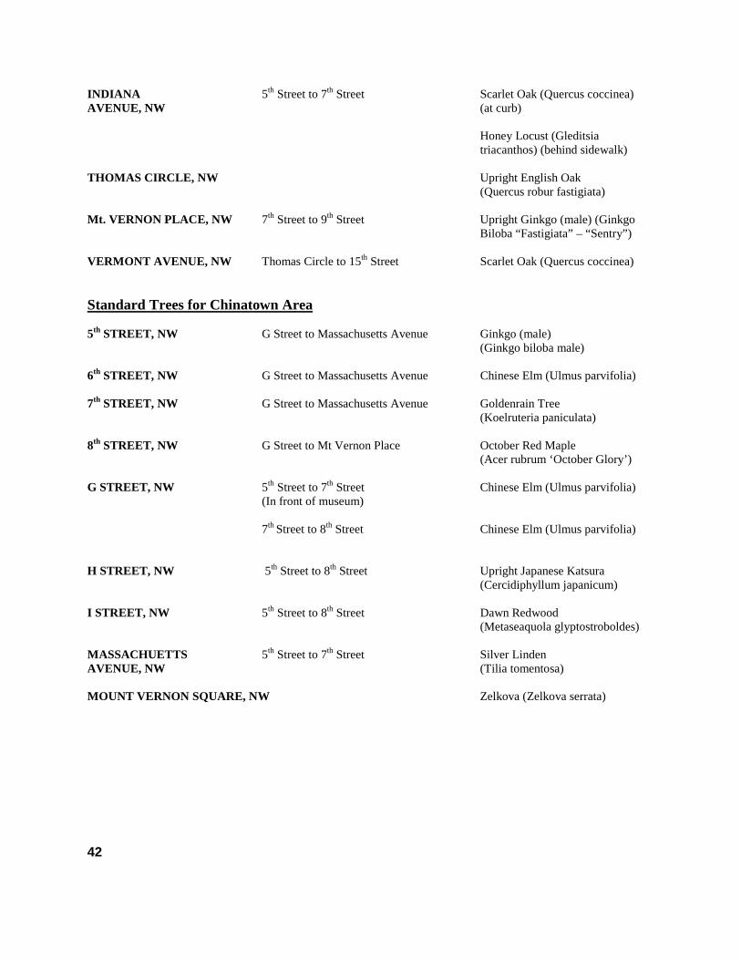
INDIANA 5th Street to 7th Street Scarlet Oak (Quercus coccinea)AVENUE, NW (at curb)
Honey Locust (Gleditsiatriacanthos) (behind sidewalk)
THOMAS CIRCLE, NW Upright English Oak(Quercus robur fastigiata)
Mt. VERNON PLACE, NW 7th Street to 9th Street Upright Ginkgo (male) (GinkgoBiloba “Fastigiata” – “Sentry”)
VERMONT AVENUE, NW Thomas Circle to 15th Street Scarlet Oak (Quercus coccinea)
Standard Trees for Chinatown Area
5th STREET, NW G Street to Massachusetts Avenue Ginkgo (male)(Ginkgo biloba male)
6th STREET, NW G Street to Massachusetts Avenue Chinese Elm (Ulmus parvifolia)
7th STREET, NW G Street to Massachusetts Avenue Goldenrain Tree(Koelruteria paniculata)
8th STREET, NW G Street to Mt Vernon Place October Red Maple(Acer rubrum ‘October Glory’)
G STREET, NW 5th Street to 7th Street Chinese Elm (Ulmus parvifolia)(In front of museum)
7th Street to 8th Street Chinese Elm (Ulmus parvifolia)
H STREET, NW 5th Street to 8th Street Upright Japanese Katsura(Cercidiphyllum japanicum)
I STREET, NW 5th Street to 8th Street Dawn Redwood(Metaseaquola glyptostroboldes)
MASSACHUETTS 5th Street to 7th Street Silver LindenAVENUE, NW (Tilia tomentosa)
MOUNT VERNON SQUARE, NW Zelkova (Zelkova serrata)
42


![Downtown Streetscape Guidelines - Burlington · The 2018 Downtown Streetscape Guidelines [the ^DSG] establishes a new vision and framework, and a set of design principles and strategies,](https://img.pdfslide.us/doc/110x75/5f040eb27e708231d40c1b71/downtown-streetscape-guidelines-burlington-the-2018-downtown-streetscape-guidelines.jpg)