Embed Size (px)
Citation preview
ElectroCraft Incorporated
ElectroCraft CompletePower™ Plus Software Version No: 5.0
Setup and Analysis Software
User’s Manual
ElectroCraft CompletePower™ Plus Motion Control Software
ElectroCraft, Inc. 2
Title: ElectroCraft CompletePower™ Plus Software Setup and Analysis Software
Type of Documentation: User Software Manual
Document Type code: SM Rev 1.0 09‐25‐09.doc
Internal File Reference: Document Number: A11102
Purpose of Documentation: This documentation describes…
• ElectroCraft CompletePower™ Plus used for the ability to automatically set up and operate any motor easily.
Record of Revisions: RELEASE NUMBER DATE DESCRIPTION COMMENTS 1.0 09/25/09 Initial Release
Copyright: ©2009 ElectroCraft MI, Inc USA. All rights Reserved.
Windows® is a registered trademark of Microsoft Corporation.
Copying this document, giving it to others and the use or communication of the contents there of without express authority, is forbidden. Offenders are liable for the payment of damages. We reserve the right to modify our products at any time. Information, specifications, and material data that appear within this user manual are subject to change without notice. For the latest revision of this manual, please check our web site or contact ElectroCraft.
Validity: The specified data is for product description purposes only and may not be deemed to be guaranteed unless expressly confirmed in the contract. All rights are reserved with respect to the content of this documentation and the availability of the product
Published by: ElectroCraft MI, Incorporated P.O. Box 7746, Ann Arbor, Michigan 48107 USA Tel.: 734‐662‐7771 • Fax: 734‐662‐3707
http://www.electrocraft.com Dept.: Sales and Marketing
ElectroCraft CompletePower™ Plus Motion Control Software
ElectroCraft, Inc. 3
Table of Contents 1 ElectroCraft CompletePower™ Plus …..…………………………………………………………………….….. 5
1.1 Overview ………….……………................................................................................... 5 Parameters & Variables …………………………………………………………………………………… 5
2 ElectroCraft CompletePower™ Plus Introduction ……..……………………..……………..…….… 6 2.1 Installation and Setup …………………....................................................................... 6 2.2 System Requirements ....…................................................................................... 6
Computer …………………………………………………………………………………………………… 6 Display …………………………………………………………………………………………………….…. 6 Printer ……………………………………………………………………………………………………….. 6 Mouse ………………………………………………………………………………………………….……. 6
Serial I/O ……………………………………………………………………………………………..…….. 6 2.3 Installing ElectroCraft CompletePower™ Plus .................................................... 7
Website ……………………………………………………………………………………………………... 7 2.4 Setting Up and Running Utility .……...…………………………………………………………..…… 8
3 Drive Configuration ………..……….………………………………………………………………………….…… 10 3.1 General Information.............................................................................................. 10 3.2 Drive Found Dialog ……………….…………………………………………………………….…………… 10
New Application …………………………………………………………………………………………. 10 Copy Drive Configuration ……………………………………………………………………………. 10 Write Application to Drive ……………………………………………………………… ……….. 11 Use Other Features ……………………………………………………………………………….….. 11
3.3 Start the Wizard ………………………………………………………………………………………………. 11 3.4 Step 1: Select Drive .…........................................................................................... 12 Firmware Part Number …………….................................................................... 12 Drive type ……………......................................................................................... 12 Nameplate Rating ……………............................................................................. 12 3.5 Step 2: Define Drive .….......................................................................................... 13 Drive Mode ……............................................................................................... 13 Drive Input …………........................................................................................... 13 Drive Output ……………………….......................................................................... 14 3.6 Step 3: Define Motor .…........................................................................................ 15 Motor Database ………..................................................................................... 15 Motor Specification …………………………………………………………………..……………….. 15 3.7 Step 4: Command Input/Output Scaling .…........................................................... 16 3.8 Step 4 Overview ……………………………………………………………………………………………… 16 Define …………………………………………………………………………………………………….….. 16 Calculation ………………………………………………………………………………….……………… 16 3.9 Step 5: Define Analog Feedback ......................................................................... 17 310 Step 5 Overview ……………………………………………………………………………………….…….. 17 Define …………………………………………………………………………………………………….….. 17 3.11 Step 6: Set Limits ................................................................................................. 18 Limits ………………………………………………………………………………………………….……… 18 Fault …………………………………………………………………………………………………….……. 18 3.12 Step 7: Motor Phasing ........................................................................................ 19 3.13 Motor Phasing Overview ………………………………………………………………………………… 19 Applied Current ……………………………………………………………………………………….… 19 Jog Speed …………………………………………………………………………………………………… 19 3.14 Step 8: Tune Control Loops ................................................................................. 22 3.15 Control Loop Overview …………………………………………………………………………………… 22
ElectroCraft CompletePower™ Plus Motion Control Software
ElectroCraft, Inc. 4
3.16 Tuning the Current Loop ………………………………………………………………………………… 23 Function Type ……………………………………………………………………………………………. 23 Amplitude …………………………………………………………………………………………………. 23 Command Period ………………………………………………………………………………………. 23 Gain Scaling ………………………………………………………………………………………………. 24 Proportional / Integral Gain ……………………………………………………………….……... 24 3.17 Tuning the Velocity Loop ………………………………………………………………………………… 25 Function Type ……………………………………………………………………………………………. 25 Amplitude …………………………………………………………………………………………………. 25 Command Period ………………………………………………………………………………………. 25 Derivative Gain …………………………………………………………………………………………. 26 Derivative Filter …………………………………………………………………………………………. 26 Measured Velocity Filter ……………………………………………………………………………. 26 3.18 Tuning the Position Loop ………………………………………………………………………………… 27 3.19 Set Advanced Parameters ………………………………………………………………………………. 28 3.20 Saving Completed Application ………………………………………………………………………… 28
4 Quick Diagnostics ……………………………………………………………………………………………………….. 29 4.1 General Description ……….…………………………………………………………………………….…. 29 4.2 How to Jog a Motor ……….…………………………………………………………………………….….. 29
5 Opening an Existing Application …….………………………………………..………………………….……. 31 6 How to Graph Variables ………………………………………………………………………………………….…. 32
6.1 Initial Graph .…................................................................................................... 32 6.2 Channel Setup Tab ............................................................................................. 33 6.3 Timebase Setup Tab ........................................................................................... 34 6.4 Trigger Setup Tab ............................................................................................... 35 6.5 Zoom Feature ………………….................................................................................. 37 In ……………………………………………………………………………………………………………….. 37 Out …………………………………………………………………………………………………………….. 37 All ……………………………………………………………………………………………………………... 37 PAN …………………………………………………………………………………………………………... 37 6.6 Function Generator Tab ..................................................................................... 38 6.7 Function Generator Overview ............................................................................ 38 6.8 Enabling the Function Generator ....................................................................... 39
7 7.0 Terminal Window …………………………………………………………………………………………… 40 7.1 How to use .…..................................................................................................... 40
ElectroCraft CompletePower™ Plus Motion Control Software
ElectroCraft, Inc. 5
1 ElectroCraft CompletePower™ Plus Software
1.1 Overview
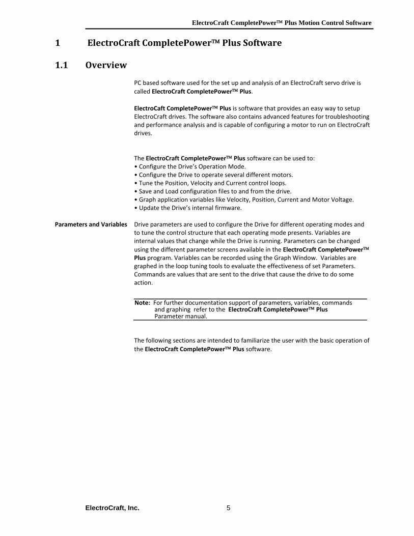
PC based software used for the set up and analysis of an ElectroCraft servo drive is called ElectroCraft CompletePower™ Plus. ElectroCaft CompletePower™ Plus is software that provides an easy way to setup ElectroCraft drives. The software also contains advanced features for troubleshooting and performance analysis and is capable of configuring a motor to run on ElectroCraft drives. The ElectroCraft CompletePower™ Plus software can be used to: • Configure the Drive’s Operation Mode. • Configure the Drive to operate several different motors. • Tune the Position, Velocity and Current control loops. • Save and Load configuration files to and from the drive. • Graph application variables like Velocity, Position, Current and Motor Voltage. • Update the Drive’s internal firmware.
Parameters and Variables Drive parameters are used to configure the Drive for different operating modes and to tune the control structure that each operating mode presents. Variables are internal values that change while the Drive is running. Parameters can be changed using the different parameter screens available in the ElectroCraft CompletePower™ Plus program. Variables can be recorded using the Graph Window. Variables are graphed in the loop tuning tools to evaluate the effectiveness of set Parameters. Commands are values that are sent to the drive that cause the drive to do some action. The following sections are intended to familiarize the user with the basic operation of the ElectroCraft CompletePower™ Plus software.
Note: For further documentation support of parameters, variables, commands and graphing refer to the ElectroCraft CompletePower™ Plus Parameter manual.
ElectroCraft CompletePower™ Plus Motion Control Software
ElectroCraft, Inc. 6
2 ElectroCraft CompletePower™ Plus Introduction
ElectroCraft CompletePower™ Plus is a Windows‐based program used for setup, parameterization, system diagnostics and motion control management. ElectroCraft CompletePower™ Plus will lead the user through a Step‐by‐Step Wizard to create the correct configuration information required for the user to run a particular motor with a particular drive. The result will be an “Application” containing all of the information required to run the motor with the drive. This chapter presents basic installation procedures and instructions on how to install and run the ElectroCraft CompletePower™ Plus software
2.1 Installation and Setup
ElectroCraft CompletePower™ Plus can be downloaded from the website @ www.electrocraft.com, see section 2.3. ElectroCraft CompletePower™ Plus is installed in English.
2.2 System Requirements
Computer ElectroCraft CompletePower™ Plus can be installed on any IBM™ PC compatible computer running…
Windows 95/98 Windows NT 4 Windows 2000 Windows XP.
Display A VGA display is required. A color monitor display makes it possible to
take full advantage of ElectroCraft CompletePower™ Plus 's graphic interface.
Printer ElectroCraft CompletePower™ Plus uses the default printer installed on your computer. For optimal resolution, especially when printing graphs, use a high‐resolution (300‐dpi) laser or ink jet printer.
Mouse A mouse or other pointing device is required to use ElectroCraft CompletePower™ Plus.
Serial I/O ElectroCraft CompletePower™ Plus can be configured to use the PC's serial port for communication between the host PC and an ElectroCraft drive. A RS‐232 serial cable is required between the host PC and the drive. A 3‐wire cable can be used for normal operation. A 5‐wire cable is required in order to update the Drive’s internal firmware.
ElectroCraft CompletePower™ Plus Motion Control Software
ElectroCraft, Inc. 7
2.3 Installing ElectroCraft CompletePower™ Plus To install ElectroCraft CompletePower™ Plus in a host computer running under Windows 95/98, Windows NT, Windows 2000, or Windows XP.
To install ElectroCraft CompletePower™ Plus software from the ElectroCraft website. Download onto a host computer running Windows 95/98/2000 or XP by doing the following:
1. Download the latest version from the website at: http://www.electrocraft.com/files/downloads
The file will be named CompletePowerPlus_v5_0_yy_xxx.zip, where 'yy' and 'xxx' are version numbers. Decompress this file, and locate the resulting file named “CompletePowerPlus_v5_0_yy_xxx_Setup.exe”.
The remainder of this page is intentionally left blank.
Note: The host computer must have a decompression utility for Windows® to open compressed files.
ElectroCraft CompletePower™ Plus Motion Control Software
ElectroCraft, Inc. 8
2.4 Setting Up and Running the Setup Utility
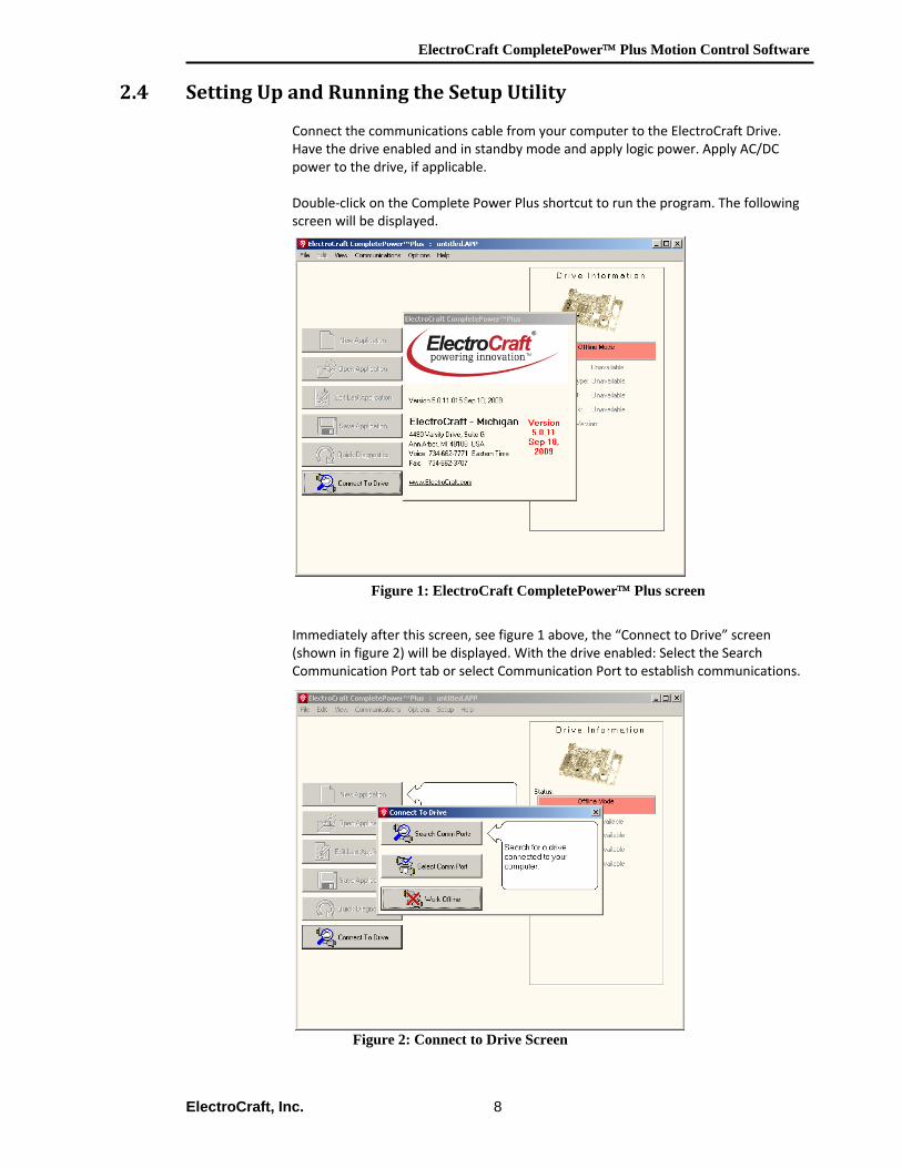
Connect the communications cable from your computer to the ElectroCraft Drive. Have the drive enabled and in standby mode and apply logic power. Apply AC/DC power to the drive, if applicable. Double‐click on the Complete Power Plus shortcut to run the program. The following screen will be displayed.
Figure 1: ElectroCraft CompletePower™ Plus screen
Immediately after this screen, see figure 1 above, the “Connect to Drive” screen (shown in figure 2) will be displayed. With the drive enabled: Select the Search Communication Port tab or select Communication Port to establish communications.
Figure 2: Connect to Drive Screen
ElectroCraft CompletePower™ Plus Motion Control Software
ElectroCraft, Inc. 9
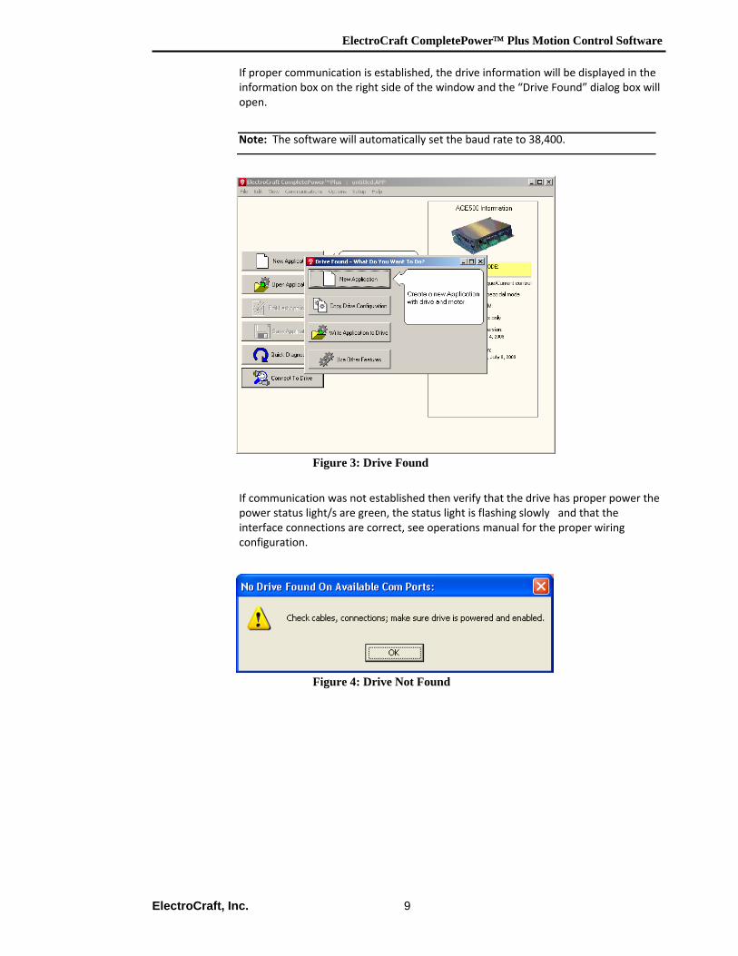
If proper communication is established, the drive information will be displayed in the information box on the right side of the window and the “Drive Found” dialog box will open.
Figure 3: Drive Found
If communication was not established then verify that the drive has proper power the power status light/s are green, the status light is flashing slowly and that the interface connections are correct, see operations manual for the proper wiring configuration.
Figure 4: Drive Not Found
Note: The software will automatically set the baud rate to 38,400.
ElectroCraft CompletePower™ Plus Motion Control Software
ElectroCraft, Inc. 10
3 Drive Configuration 3.1 General Information
The Setup Utility was designed to make it easier for the user to set up and run a motor. The utility takes the user through a step‐by‐step setup wizard and configures parameters needed to run a specific motor. This is all done automatically. The parameters will be saved into the drive after step eight. The user may also open and/or edit an existing application and adjust individual parameters as necessary leaving all other settings unchanged. In some incidences, the drive may come delivered with a set of parameters preconfigured from the factory for a known motor. In other cases, troubleshooting the drive performance, under the direction of ElectroCraft, Inc personnel, may require the customer to change specific parameters. For these purposes, please refer to the ElectroCraft CompletePower™ Plus Parameter application manual.
3.2 Drive Found Dialog
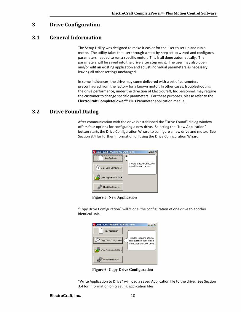
After communication with the drive is established the “Drive Found” dialog window offers four options for configuring a new drive. Selecting the “New Application” button starts the Drive Configuration Wizard to configure a new drive and motor. See Section 3.4 for further information on using the Drive Configuration Wizard.
Figure 5: New Application
“Copy Drive Configuration” will ‘clone’ the configuration of one drive to another identical unit.
Figure 6: Copy Drive Configuration
“Write Application to Drive” will load a saved Application file to the drive. See Section 3.4 for information on creating application files
ElectroCraft CompletePower™ Plus Motion Control Software
ElectroCraft, Inc. 11
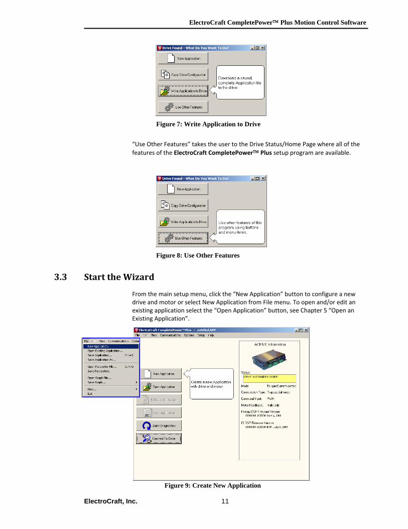
Figure 7: Write Application to Drive
“Use Other Features” takes the user to the Drive Status/Home Page where all of the features of the ElectroCraft CompletePower™ Plus setup program are available.
Figure 8: Use Other Features
3.3 Start the Wizard
From the main setup menu, click the “New Application” button to configure a new drive and motor or select New Application from File menu. To open and/or edit an existing application select the “Open Application” button, see Chapter 5 “Open an Existing Application”.
Figure 9: Create New Application
ElectroCraft CompletePower™ Plus Motion Control Software
ElectroCraft, Inc. 12
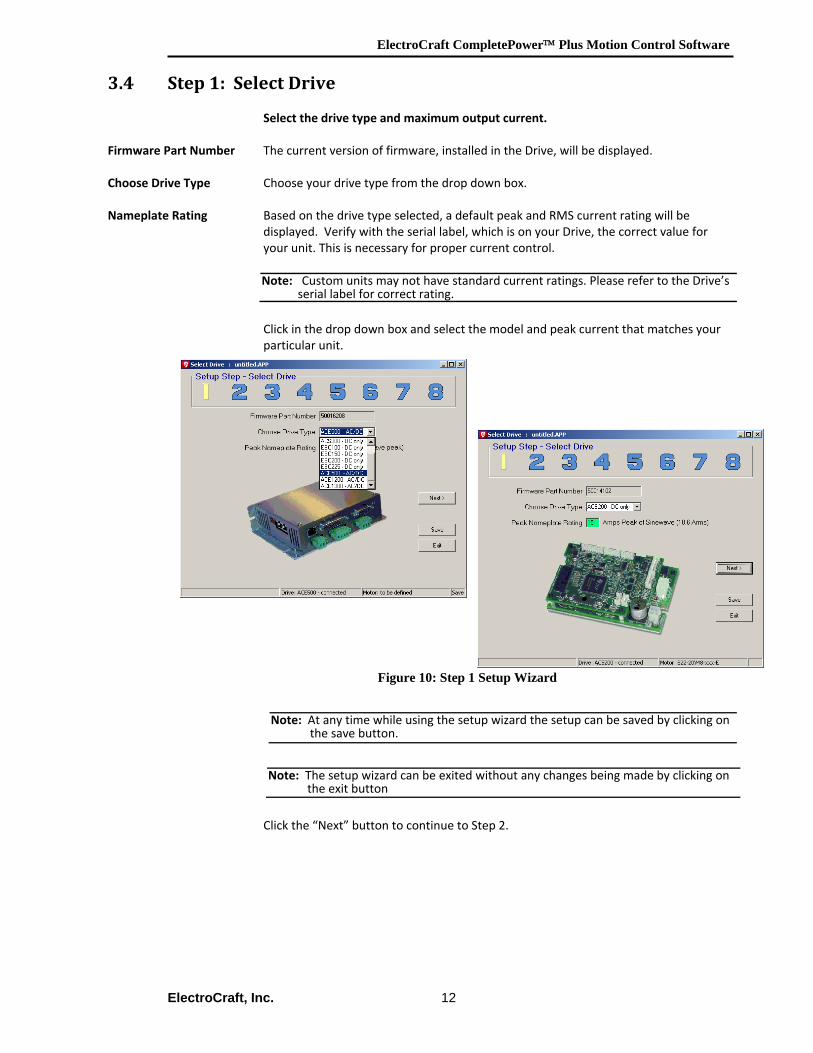
3.4 Step 1: Select Drive
Select the drive type and maximum output current.
Firmware Part Number The current version of firmware, installed in the Drive, will be displayed.
Choose Drive Type Choose your drive type from the drop down box. Nameplate Rating Based on the drive type selected, a default peak and RMS current rating will be
displayed. Verify with the serial label, which is on your Drive, the correct value for your unit. This is necessary for proper current control.
Click in the drop down box and select the model and peak current that matches your particular unit.
Figure 10: Step 1 Setup Wizard
Click the “Next” button to continue to Step 2.
Note: Custom units may not have standard current ratings. Please refer to the Drive’s serial label for correct rating.
Note: At any time while using the setup wizard the setup can be saved by clicking on the save button.
Note: The setup wizard can be exited without any changes being made by clicking on the exit button
ElectroCraft CompletePower™ Plus Motion Control Software
ElectroCraft, Inc. 13
3.5 Step 2: Define Drive
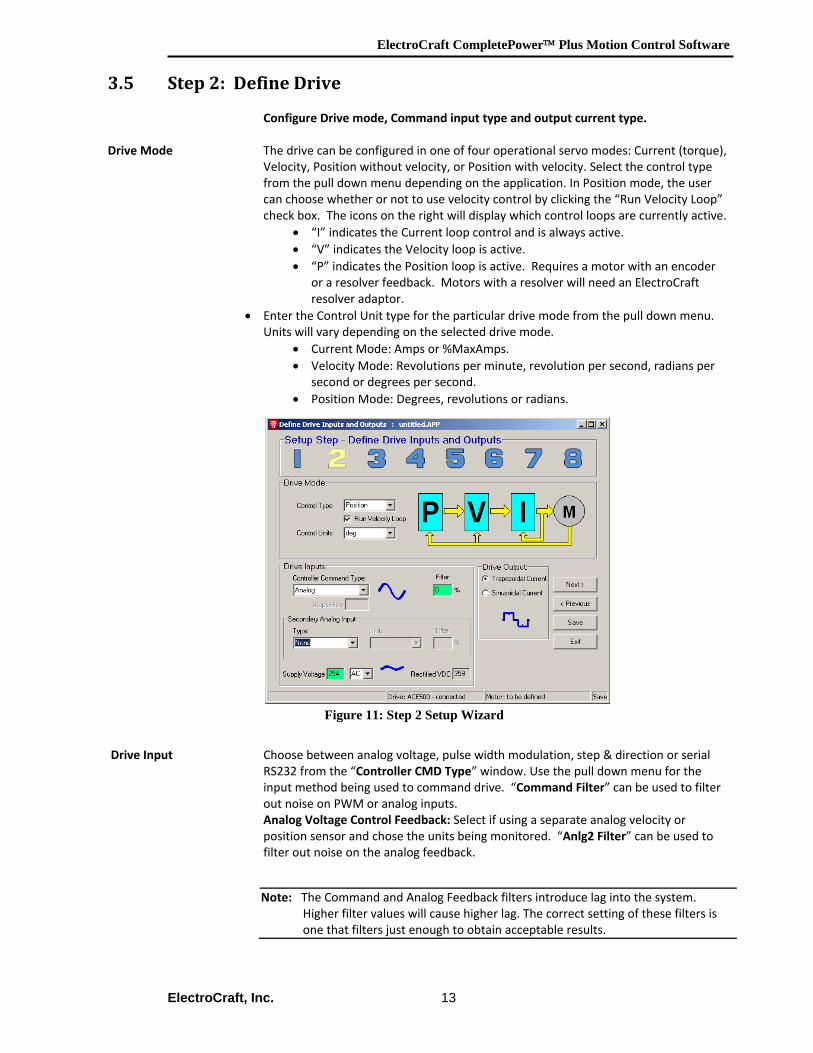
Configure Drive mode, Command input type and output current type. Drive Mode The drive can be configured in one of four operational servo modes: Current (torque),
Velocity, Position without velocity, or Position with velocity. Select the control type from the pull down menu depending on the application. In Position mode, the user can choose whether or not to use velocity control by clicking the “Run Velocity Loop” check box. The icons on the right will display which control loops are currently active.
• “I” indicates the Current loop control and is always active. • “V” indicates the Velocity loop is active. • “P” indicates the Position loop is active. Requires a motor with an encoder
or a resolver feedback. Motors with a resolver will need an ElectroCraft resolver adaptor.
• Enter the Control Unit type for the particular drive mode from the pull down menu. Units will vary depending on the selected drive mode.
• Current Mode: Amps or %MaxAmps. • Velocity Mode: Revolutions per minute, revolution per second, radians per
second or degrees per second. • Position Mode: Degrees, revolutions or radians.
Figure 11: Step 2 Setup Wizard
Drive Input Choose between analog voltage, pulse width modulation, step & direction or serial
RS232 from the “Controller CMD Type” window. Use the pull down menu for the input method being used to command drive. “Command Filter” can be used to filter out noise on PWM or analog inputs. Analog Voltage Control Feedback: Select if using a separate analog velocity or position sensor and chose the units being monitored. “Anlg2 Filter” can be used to filter out noise on the analog feedback.
Note: The Command and Analog Feedback filters introduce lag into the system. Higher filter values will cause higher lag. The correct setting of these filters is one that filters just enough to obtain acceptable results.

ElectroCraft CompletePower™ Plus Motion Control Software
ElectroCraft, Inc. 14
Supply Voltage: Adjust the supply voltage to the correct input voltage being used to power the drive. If using AC input, the rectified DC voltage will be displayed.
Drive Output The Drive output can be either Trapezoidal or sinusoidal. Sine mode can run with
either encoder with hall synchronize feedback or using only hall feedback. Click the “Next” button to continue to Step 3.
The remainder of this page is intentionally left blank.
ElectroCraft CompletePower™ Plus Motion Control Software
ElectroCraft, Inc. 15
3.6 Step 3: Define Motor
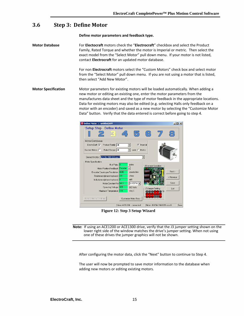
Define motor parameters and feedback type.
Motor Database For Electocraft motors check the “Electrocraft” checkbox and select the Product Family, Rated Torque and whether the motor is Imperial or metric. Then select the exact model from the “Select Motor” pull down menu. If your motor is not listed, contact Electrocraft for an updated motor database.
For non Electrocraft motors select the “Custom Motors” check box and select motor from the “Select Motor” pull down menu. If you are not using a motor that is listed, then select “Add New Motor”.
Motor Specification Motor parameters for existing motors will be loaded automatically. When adding a new motor or editing an existing one, enter the motor parameters from the manufactures data sheet and the type of motor feedback in the appropriate locations. Data for existing motors may also be edited (e.g. selecting Halls only feedback on a motor with an encoder) and saved as a new motor by selecting the “Customize Motor Data” button. Verify that the data entered is correct before going to step 4.
Figure 12: Step 3 Setup Wizard After configuring the motor data, click the “Next” button to continue to Step 4. The user will now be prompted to save motor information to the database when adding new motors or editing existing motors.
Note: If using an ACE1200 or ACE1300 drive, verify that the J3 jumper setting shown on the lower right side of the window matches the drive’s jumper setting. When not using one of these drives the jumper graphics will not be shown.
ElectroCraft CompletePower™ Plus Motion Control Software
ElectroCraft, Inc. 16
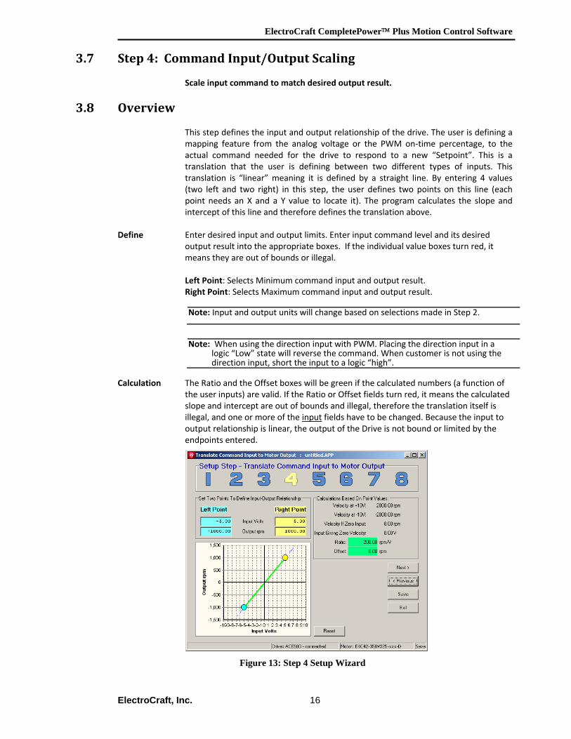
3.7 Step 4: Command Input/Output Scaling Scale input command to match desired output result.
3.8 Overview This step defines the input and output relationship of the drive. The user is defining a mapping feature from the analog voltage or the PWM on‐time percentage, to the actual command needed for the drive to respond to a new “Setpoint”. This is a translation that the user is defining between two different types of inputs. This translation is “linear” meaning it is defined by a straight line. By entering 4 values (two left and two right) in this step, the user defines two points on this line (each point needs an X and a Y value to locate it). The program calculates the slope and intercept of this line and therefore defines the translation above.
Define Enter desired input and output limits. Enter input command level and its desired output result into the appropriate boxes. If the individual value boxes turn red, it means they are out of bounds or illegal.
Left Point: Selects Minimum command input and output result. Right Point: Selects Maximum command input and output result.
Calculation The Ratio and the Offset boxes will be green if the calculated numbers (a function of
the user inputs) are valid. If the Ratio or Offset fields turn red, it means the calculated slope and intercept are out of bounds and illegal, therefore the translation itself is illegal, and one or more of the input fields have to be changed. Because the input to output relationship is linear, the output of the Drive is not bound or limited by the endpoints entered.
Figure 13: Step 4 Setup Wizard
Note: Input and output units will change based on selections made in Step 2.
Note: When using the direction input with PWM. Placing the direction input in a logic “Low” state will reverse the command. When customer is not using the direction input, short the input to a logic “high”.
ElectroCraft CompletePower™ Plus Motion Control Software
ElectroCraft, Inc. 17
Example: If the Drive is configured to run at 1000rpm with a +5vdc command input, then it will run at 2,000 rpm when a +10vdc command signal is applied. Click next to continue to step 5.
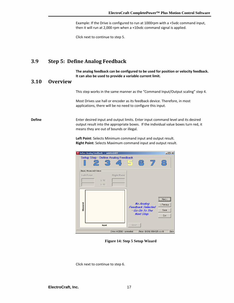
3.9 Step 5: Define Analog Feedback
The analog feedback can be configured to be used for position or velocity feedback. It can also be used to provide a variable current limit.
3.10 Overview
This step works in the same manner as the “Command Input/Output scaling” step 4. Most Drives use hall or encoder as its feedback device. Therefore, in most applications, there will be no need to configure this input.
Define Enter desired input and output limits. Enter input command level and its desired output result into the appropriate boxes. If the individual value boxes turn red, it means they are out of bounds or illegal.
Left Point: Selects Minimum command input and output result. Right Point: Selects Maximum command input and output result.
Figure 14: Step 5 Setup Wizard
Click next to continue to step 6.
ElectroCraft CompletePower™ Plus Motion Control Software
ElectroCraft, Inc. 18
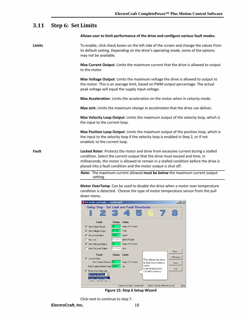
3.11 Step 6: Set Limits
Allows user to limit performance of the drive and configure various fault modes.
Limits To enable, click check boxes on the left side of the screen and change the values from its default setting. Depending on the drive’s operating mode, some of the options may not be available. Max Current Output: Limits the maximum current that the drive is allowed to output to the motor. Max Voltage Output: Limits the maximum voltage the drive is allowed to output to the motor. This is an average limit, based on PWM output percentage. The actual peak voltage will equal the supply input voltage. Max Acceleration: Limits the acceleration on the motor when in velocity mode. Max Jerk: Limits the maximum change in acceleration that the drive can deliver. Max Velocity Loop Output: Limits the maximum output of the velocity loop, which is the input to the current loop. Max Position Loop Output: Limits the maximum output of the position loop, which is the input to the velocity loop if the velocity loop is enabled in Step 2, or if not enabled, to the current loop.
Fault Locked Rotor: Protects the motor and drive from excessive current during a stalled condition. Select the current output that the drive must exceed and time, in milliseconds, the motor is allowed to remain in a stalled condition before the drive is placed into a fault condition and the motor output is shut off.
Motor OverTemp: Can be used to disable the drive when a motor over temperature condition is detected. Choose the type of motor temperature sensor from the pull down menu.
Figure 15: Step 6 Setup Wizard
Click next to continue to step 7.
Note: The maximum current allowedmust be below the maximum current output setting.
ElectroCraft CompletePower™ Plus Motion Control Software
ElectroCraft, Inc. 19
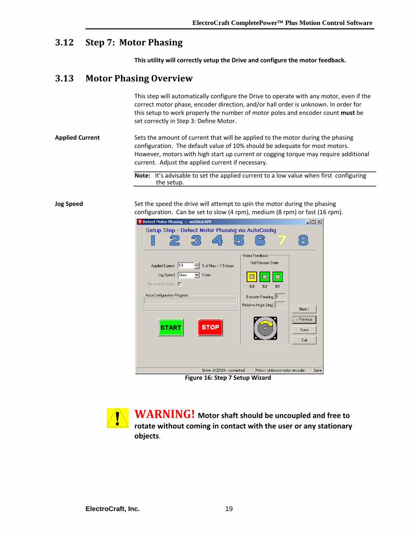
3.12 Step 7: Motor Phasing
This utility will correctly setup the Drive and configure the motor feedback.
3.13 Motor Phasing Overview This step will automatically configure the Drive to operate with any motor, even if the
correct motor phase, encoder direction, and/or hall order is unknown. In order for this setup to work properly the number of motor poles and encoder count must be set correctly in Step 3: Define Motor.
Applied Current Sets the amount of current that will be applied to the motor during the phasing configuration. The default value of 10% should be adequate for most motors. However, motors with high start up current or cogging torque may require additional current. Adjust the applied current if necessary.
Jog Speed Set the speed the drive will attempt to spin the motor during the phasing
configuration. Can be set to slow (4 rpm), medium (8 rpm) or fast (16 rpm).
Figure 16: Step 7 Setup Wizard
WARNING! Motor shaft should be uncoupled and free to rotate without coming in contact with the user or any stationary objects.
Note: It’s advisable to set the applied current to a low value when first configuring the setup.
ElectroCraft CompletePower™ Plus Motion Control Software
ElectroCraft, Inc. 20
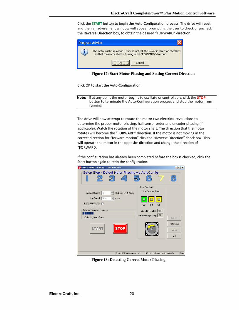
Click the START button to begin the Auto‐Configuration process. The drive will reset and then an advisement window will appear prompting the user to check or uncheck the Reverse Direction box, to obtain the desired “FORWARD” direction.
Figure 17: Start Motor Phasing and Setting Correct Direction
Click OK to start the Auto‐Configuration. The drive will now attempt to rotate the motor two electrical revolutions to determine the proper motor phasing, hall sensor order and encoder phasing (if applicable). Watch the rotation of the motor shaft. The direction that the motor rotates will become the “FORWARD” direction. If the motor is not moving in the correct direction for “forward motion” click the “Reverse Direction” check box. This will operate the motor in the opposite direction and change the direction of “FORWARD. If the configuration has already been completed before the box is checked, click the Start button again to redo the configuration.
Figure 18: Detecting Correct Motor Phasing
Note: If at any point the motor begins to oscillate uncontrollably, click the STOPbutton to terminate the Auto‐Configuration process and stop the motor from running.
ElectroCraft CompletePower™ Plus Motion Control Software
ElectroCraft, Inc. 21
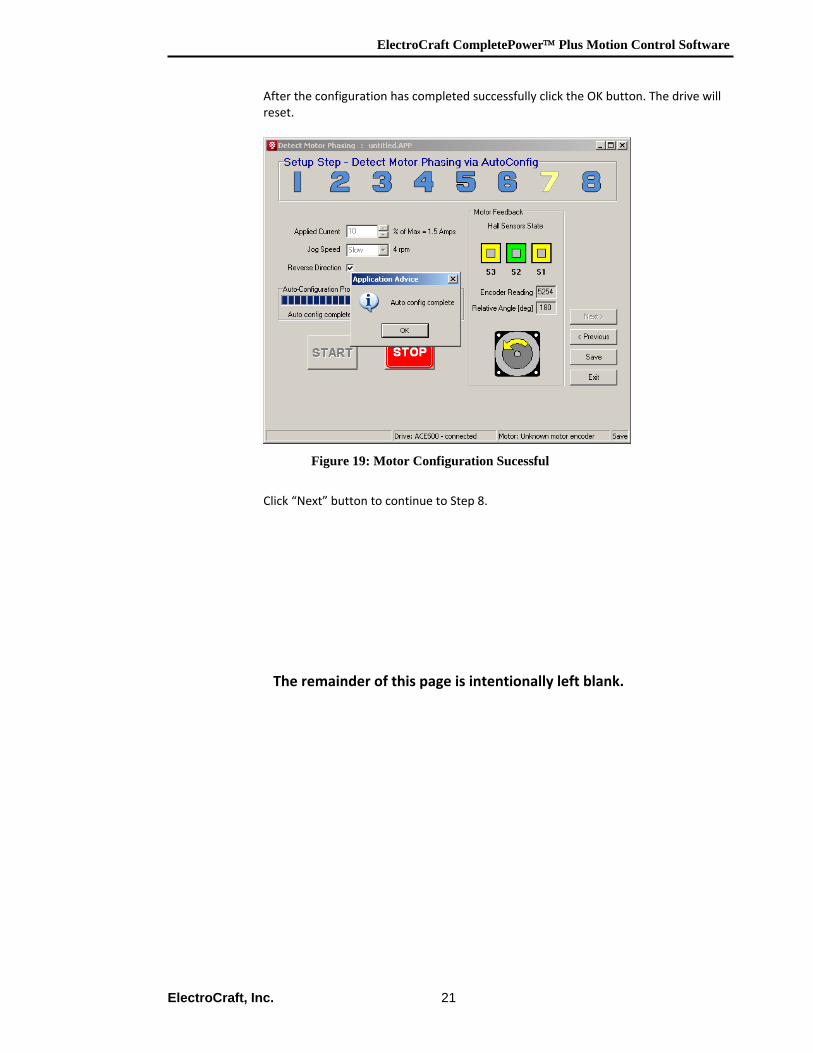
After the configuration has completed successfully click the OK button. The drive will reset.
Figure 19: Motor Configuration Sucessful
Click “Next” button to continue to Step 8.
The remainder of this page is intentionally left blank.
ElectroCraft CompletePower™ Plus Motion Control Software
ElectroCraft, Inc. 22
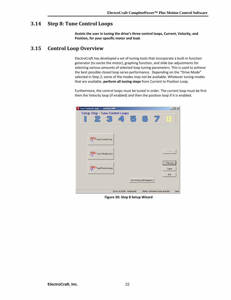
3.14 Step 8: Tune Control Loops
Assists the user in tuning the drive’s three control loops, Current, Velocity, and Position, for your specific motor and load.
3.15 Control Loop Overview
ElectroCraft has developed a set of tuning tools that incorporate a built‐in function generator (to excite the motor), graphing function, and slide bar adjustments for selecting various amounts of selected loop tuning parameters. This is used to achieve the best possible closed loop servo performance. Depending on the “Drive Mode” selected in Step 2, some of the modes may not be available. Whatever tuning modes that are available, perform all tuning steps from Current to Position Loop. Furthermore, the control loops must be tuned in order. The current loop must be first then the Velocity loop (if enabled) and then the position loop if it is enabled.
Figure 20: Step 8 Setup Wizard
ElectroCraft CompletePower™ Plus Motion Control Software
ElectroCraft, Inc. 23
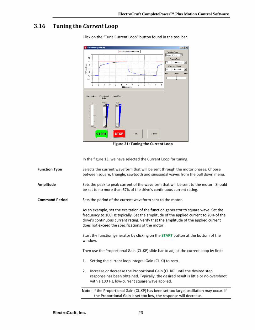
3.16 Tuning the Current Loop Click on the “Tune Current Loop” button found in the tool bar.
Figure 21: Tuning the Current Loop In the figure 13, we have selected the Current Loop for tuning.
Function Type Selects the current waveform that will be sent through the motor phases. Choose between square, triangle, sawtooth and sinusoidal waves from the pull down menu.
Amplitude Sets the peak to peak current of the waveform that will be sent to the motor. Should
be set to no more than 67% of the drive’s continuous current rating. Command Period Sets the period of the current waveform sent to the motor. As an example, set the excitation of the function generator to square wave. Set the
frequency to 100 Hz typically. Set the amplitude of the applied current to 20% of the drive’s continuous current rating. Verify that the amplitude of the applied current does not exceed the specifications of the motor. Start the function generator by clicking on the START button at the bottom of the window. Then use the Proportional Gain (CL.KP) slide bar to adjust the current Loop by first: 1. Setting the current loop Integral Gain (CL.KI) to zero. 2. Increase or decrease the Proportional Gain (CL.KP) until the desired step
response has been obtained. Typically, the desired result is little or no overshoot with a 100 Hz, low‐current square wave applied.
Note: If the Proportional Gain (CL.KP) has been set too large, oscillation may occur. If the Proportional Gain is set too low, the response will decrease.
ElectroCraft CompletePower™ Plus Motion Control Software
ElectroCraft, Inc. 24
3. Adjust the current loop Integral Gain (CL.KI) from zero until the desired result has been obtained. If the value is set too high then this will cause the loop to overshoot, to low and the commanded Setpoint value will never be achieved.
Once the desired current response has been obtained. Click the STOP button to stop the function generator, and then select the OK button to save these values.
Gain Scaling The Gain Scaling (CL.SH) is a multiplier applied to both the Proportional (KP) and Integral (KI) gain values. When adjusting gain values, it is strongly recommended to use the lowest possible value for the gain scaling. For example, use KP=10000, KI=2000 and SH=0, rather than KP=5000, KI=1000 and SH=1.
Proportional / The Proportional and Integral gain settings are integer values between 0 and +32767. Integral Gain If CL.SH = 1, then the KP & KI range of 0 to 32,767 represents 0 to 200% gain. If CL.SH = 2, then the KP & KI range of 0 to 32,767 represents 0 to 400% gain, etc.
If the amplifier is to be used in current mode only, skip the Velocity and Position Loop tuning steps in sections 3.16 and 3.17. The remainder of this page is intentionally left blank.
Note: At any time if you wish to exit the tuning program without saving the newcurrent tuning values, select the Cancel button
ElectroCraft CompletePower™ Plus Motion Control Software
ElectroCraft, Inc. 25
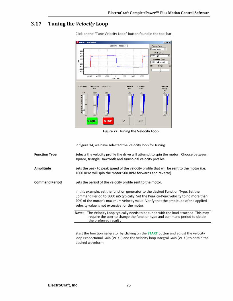
3.17 Tuning the Velocity Loop
Click on the “Tune Velocity Loop” button found in the tool bar.
Figure 22: Tuning the Velocity Loop In figure 14, we have selected the Velocity loop for tuning.
Function Type Selects the velocity profile the drive will attempt to spin the motor. Choose between square, triangle, sawtooth and sinusoidal velocity profiles.
Amplitude Sets the peak to peak speed of the velocity profile that will be sent to the motor (i.e.
1000 RPM will spin the motor 500 RPM forwards and reverse) Command Period Sets the period of the velocity profile sent to the motor.
In this example, set the function generator to the desired Function Type. Set the Command Period to 3000 mS typically. Set the Peak‐to‐Peak velocity to no more than 20% of the motor’s maximum velocity value. Verify that the amplitude of the applied velocity value is not excessive for the motor. Start the function generator by clicking on the START button and adjust the velocity loop Proportional Gain (VL.KP) and the velocity loop Integral Gain (VL.KI) to obtain the desired waveform.
Note: The Velocity Loop typically needs to be tuned with the load attached. This mayrequire the user to change the function type and command period to obtain the preferred result .
ElectroCraft CompletePower™ Plus Motion Control Software
ElectroCraft, Inc. 26
Then use the Proportional Gain (VL.KP) slide bar to adjust the Velocity Loop by first: 1. Setting the velocity loop integral gain (VL.KI) to zero. 2. Increase or decrease the Proportional Gain (VL.KP) until the desired step
response has been obtained. Typically, the desired result is little or no overshoot, with a 3000mS slow‐speed square wave applied.
3. Adjust the Velocity Loop gain (VL.KI) until the desired response has been
obtained. Once the desired velocity step response has been obtained, save the values to the drive. Click the STOP button to stop the function generator, and then select the OK button to save these values.
Derivative Gain Derivative gain works on the “rate of change” of velocity error. In most applications, derivative gain is not necessary.
Derivative Filter The derivative filter is used to reduce the sensitivity to the noise in the error term. Measured Velocity Filter The velocity filter uses a digital averaging method. Typically, this filter is only used
when a high‐resolution feedback device, like an encoder, is not available and only the hall sensors are available as a feedback device. The velocity filter will help to correct for irregular halls signals. When using a motor with an encoder, the filter value should be set to zero.
If the amplifier is to be used in velocity mode only, skip the Position Loop tuning step in the next section 3.17.
Note: The velocity filter introduces lag into the velocity feedback. Higher filter valueswill cause higher lag. The correct setting of the velocity filter is one that filters the velocity only enough to obtain acceptable results.
ElectroCraft CompletePower™ Plus Motion Control Software
ElectroCraft, Inc. 27
3.18 Tuning the Position Loop
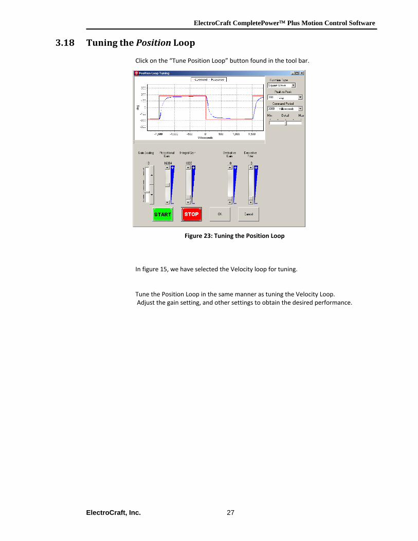
Click on the “Tune Position Loop” button found in the tool bar.
Figure 23: Tuning the Position Loop
In figure 15, we have selected the Velocity loop for tuning. Tune the Position Loop in the same manner as tuning the Velocity Loop. Adjust the gain setting, and other settings to obtain the desired performance.
ElectroCraft CompletePower™ Plus Motion Control Software
ElectroCraft, Inc. 28
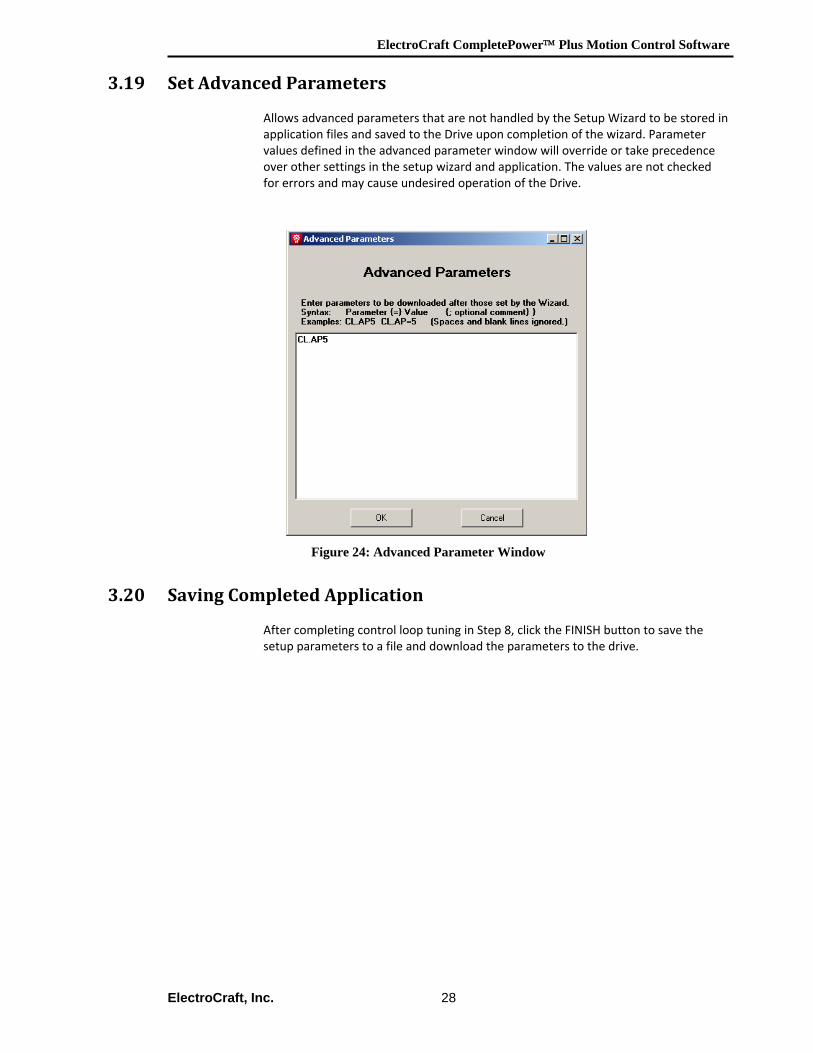
3.19 Set Advanced Parameters Allows advanced parameters that are not handled by the Setup Wizard to be stored in application files and saved to the Drive upon completion of the wizard. Parameter values defined in the advanced parameter window will override or take precedence over other settings in the setup wizard and application. The values are not checked for errors and may cause undesired operation of the Drive.
Figure 24: Advanced Parameter Window
3.20 Saving Completed Application After completing control loop tuning in Step 8, click the FINISH button to save the setup parameters to a file and download the parameters to the drive.
ElectroCraft CompletePower™ Plus Motion Control Software
ElectroCraft, Inc. 29
4 Quick Diagnostics
4.1 General Description
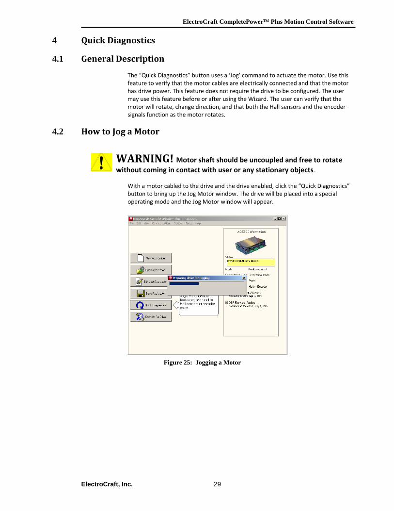
The “Quick Diagnostics” button uses a ‘Jog’ command to actuate the motor. Use this feature to verify that the motor cables are electrically connected and that the motor has drive power. This feature does not require the drive to be configured. The user may use this feature before or after using the Wizard. The user can verify that the motor will rotate, change direction, and that both the Hall sensors and the encoder signals function as the motor rotates.
4.2 How to Jog a Motor
WARNING! Motor shaft should be uncoupled and free to rotate without coming in contact with user or any stationary objects.
With a motor cabled to the drive and the drive enabled, click the “Quick Diagnostics” button to bring up the Jog Motor window. The drive will be placed into a special operating mode and the Jog Motor window will appear.
Figure 25: Jogging a Motor
ElectroCraft CompletePower™ Plus Motion Control Software
ElectroCraft, Inc. 30
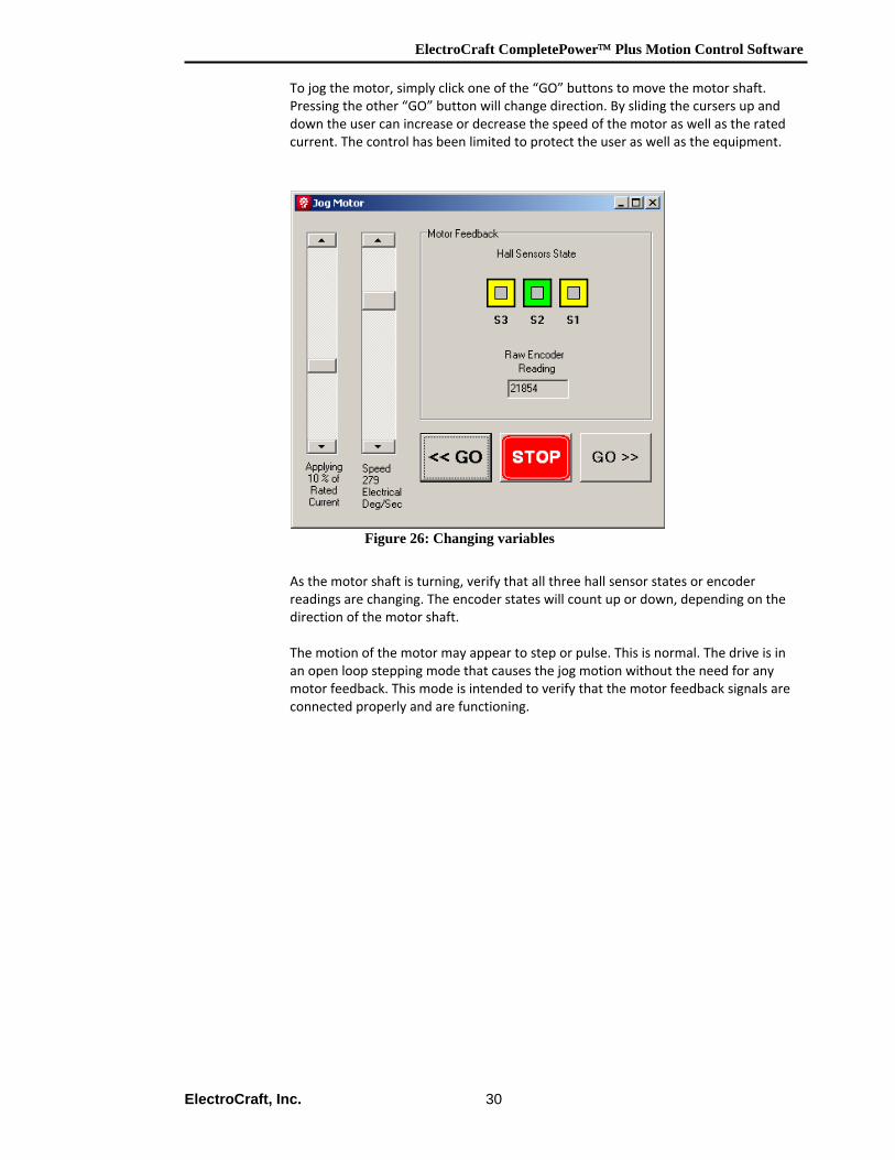
To jog the motor, simply click one of the “GO” buttons to move the motor shaft. Pressing the other “GO” button will change direction. By sliding the cursers up and down the user can increase or decrease the speed of the motor as well as the rated current. The control has been limited to protect the user as well as the equipment.
Figure 26: Changing variables
As the motor shaft is turning, verify that all three hall sensor states or encoder readings are changing. The encoder states will count up or down, depending on the direction of the motor shaft. The motion of the motor may appear to step or pulse. This is normal. The drive is in an open loop stepping mode that causes the jog motion without the need for any motor feedback. This mode is intended to verify that the motor feedback signals are connected properly and are functioning.
ElectroCraft CompletePower™ Plus Motion Control Software
ElectroCraft, Inc. 31
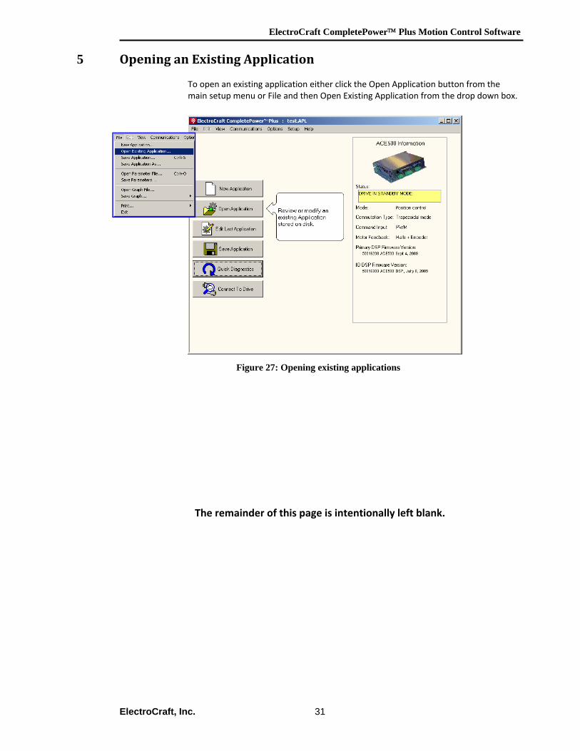
5 Opening an Existing Application To open an existing application either click the Open Application button from the main setup menu or File and then Open Existing Application from the drop down box.
Figure 27: Opening existing applications
The remainder of this page is intentionally left blank.
ElectroCraft CompletePower™ Plus Motion Control Software
ElectroCraft, Inc. 32
6 How to Graph Drive Variables Variables can be captured and displayed graphically using the Graph screen. In this way, control loop tuning can be evaluated.
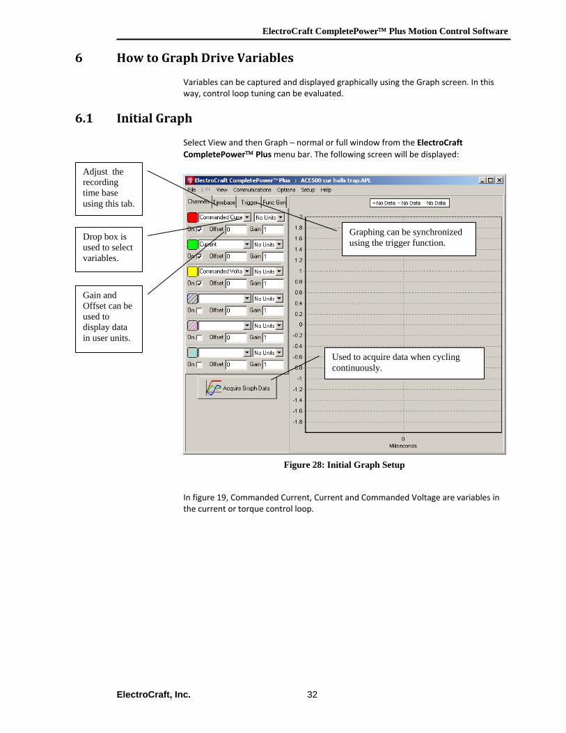
6.1 Initial Graph Select View and then Graph – normal or full window from the ElectroCraft CompletePower™ Plus menu bar. The following screen will be displayed:
Figure 28: Initial Graph Setup
In figure 19, Commanded Current, Current and Commanded Voltage are variables in the current or torque control loop.
Adjust the recording time base using this tab.
Drop box is used to select variables.
Gain and Offset can be used to display data in user units.
Graphing can be synchronized using the trigger function.
Used to acquire data when cycling continuously.
ElectroCraft CompletePower™ Plus Motion Control Software
ElectroCraft, Inc. 33
6.2 Channel Setup Tab
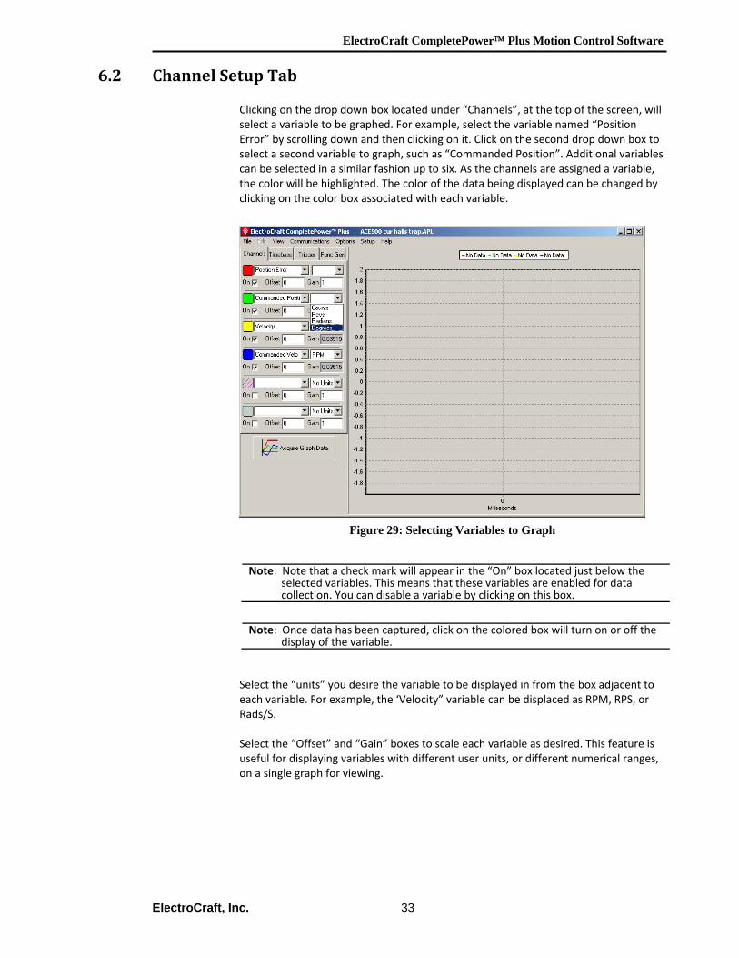
Clicking on the drop down box located under “Channels”, at the top of the screen, will select a variable to be graphed. For example, select the variable named “Position Error” by scrolling down and then clicking on it. Click on the second drop down box to select a second variable to graph, such as “Commanded Position”. Additional variables can be selected in a similar fashion up to six. As the channels are assigned a variable, the color will be highlighted. The color of the data being displayed can be changed by clicking on the color box associated with each variable.
Figure 29: Selecting Variables to Graph
Select the “units” you desire the variable to be displayed in from the box adjacent to each variable. For example, the ‘Velocity” variable can be displaced as RPM, RPS, or Rads/S. Select the “Offset” and “Gain” boxes to scale each variable as desired. This feature is useful for displaying variables with different user units, or different numerical ranges, on a single graph for viewing.
Note: Note that a check mark will appear in the “On” box located just below the selected variables. This means that these variables are enabled for data collection. You can disable a variable by clicking on this box.
Note: Once data has been captured, click on the colored box will turn on or off the display of the variable.
ElectroCraft CompletePower™ Plus Motion Control Software
ElectroCraft, Inc. 34
6.3 Timebase Setup Tab
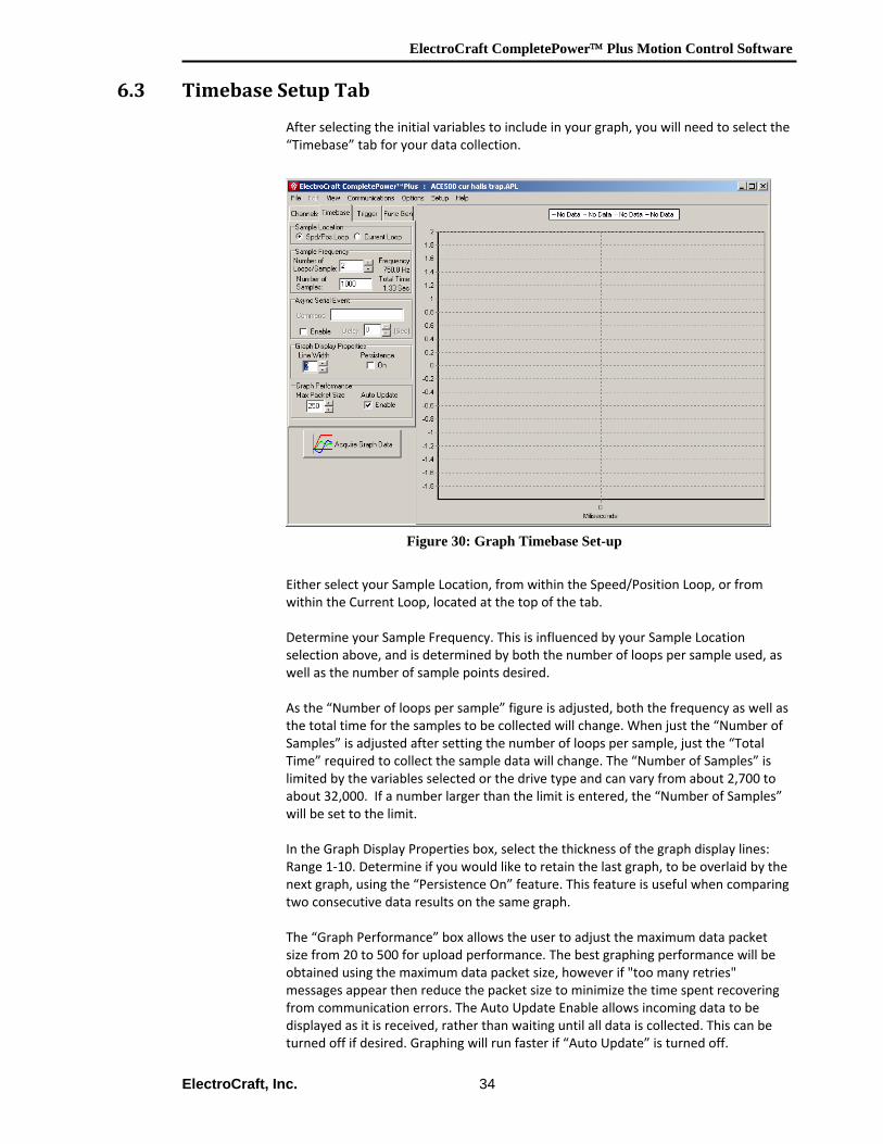
After selecting the initial variables to include in your graph, you will need to select the “Timebase” tab for your data collection.
Figure 30: Graph Timebase Set-up
Either select your Sample Location, from within the Speed/Position Loop, or from within the Current Loop, located at the top of the tab. Determine your Sample Frequency. This is influenced by your Sample Location selection above, and is determined by both the number of loops per sample used, as well as the number of sample points desired. As the “Number of loops per sample” figure is adjusted, both the frequency as well as the total time for the samples to be collected will change. When just the “Number of Samples” is adjusted after setting the number of loops per sample, just the “Total Time” required to collect the sample data will change. The “Number of Samples” is limited by the variables selected or the drive type and can vary from about 2,700 to about 32,000. If a number larger than the limit is entered, the “Number of Samples” will be set to the limit. In the Graph Display Properties box, select the thickness of the graph display lines: Range 1‐10. Determine if you would like to retain the last graph, to be overlaid by the next graph, using the “Persistence On” feature. This feature is useful when comparing two consecutive data results on the same graph. The “Graph Performance” box allows the user to adjust the maximum data packet size from 20 to 500 for upload performance. The best graphing performance will be obtained using the maximum data packet size, however if "too many retries" messages appear then reduce the packet size to minimize the time spent recovering from communication errors. The Auto Update Enable allows incoming data to be displayed as it is received, rather than waiting until all data is collected. This can be turned off if desired. Graphing will run faster if “Auto Update” is turned off.
ElectroCraft CompletePower™ Plus Motion Control Software
ElectroCraft, Inc. 35
6.4 Trigger Setup Tab
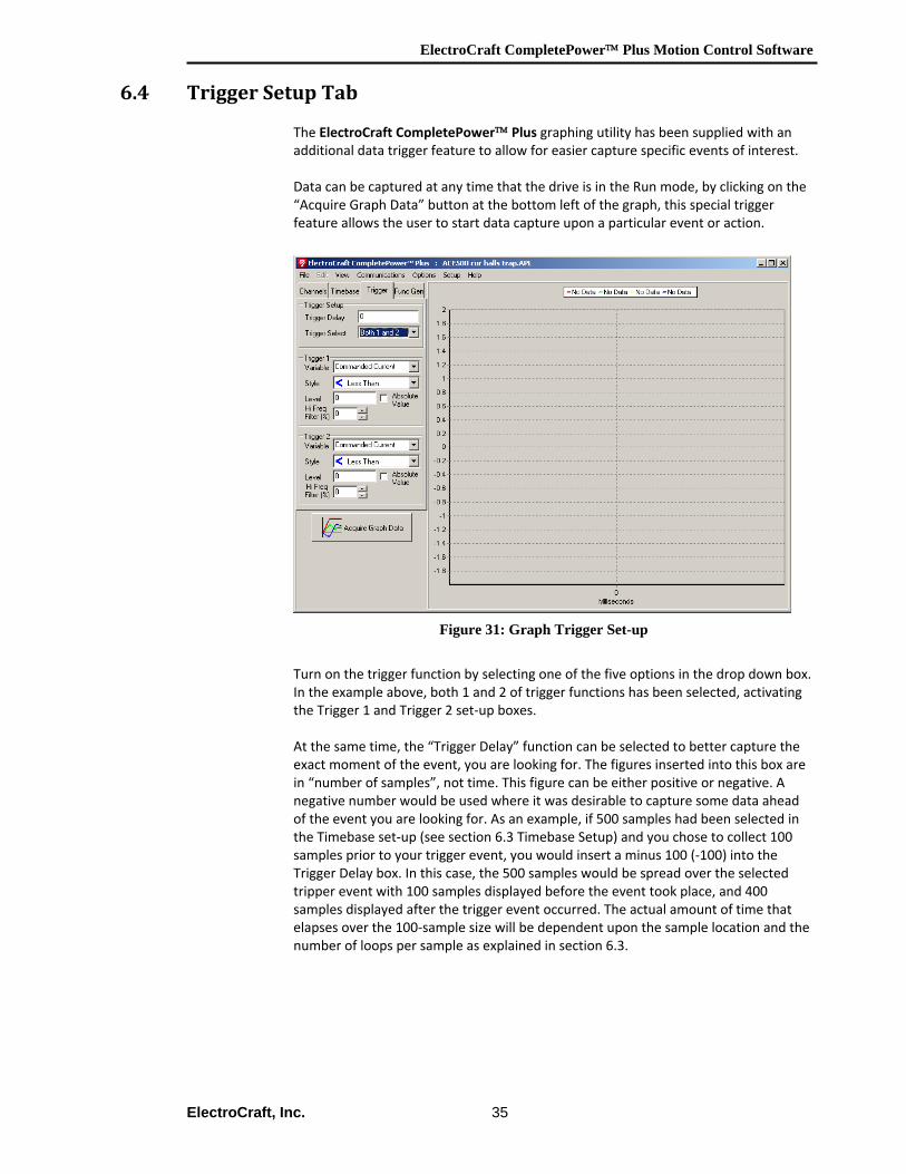
The ElectroCraft CompletePower™ Plus graphing utility has been supplied with an additional data trigger feature to allow for easier capture specific events of interest. Data can be captured at any time that the drive is in the Run mode, by clicking on the “Acquire Graph Data” button at the bottom left of the graph, this special trigger feature allows the user to start data capture upon a particular event or action.
Figure 31: Graph Trigger Set-up
Turn on the trigger function by selecting one of the five options in the drop down box. In the example above, both 1 and 2 of trigger functions has been selected, activating the Trigger 1 and Trigger 2 set‐up boxes. At the same time, the “Trigger Delay” function can be selected to better capture the exact moment of the event, you are looking for. The figures inserted into this box are in “number of samples”, not time. This figure can be either positive or negative. A negative number would be used where it was desirable to capture some data ahead of the event you are looking for. As an example, if 500 samples had been selected in the Timebase set‐up (see section 6.3 Timebase Setup) and you chose to collect 100 samples prior to your trigger event, you would insert a minus 100 (‐100) into the Trigger Delay box. In this case, the 500 samples would be spread over the selected tripper event with 100 samples displayed before the event took place, and 400 samples displayed after the trigger event occurred. The actual amount of time that elapses over the 100‐sample size will be dependent upon the sample location and the number of loops per sample as explained in section 6.3.
ElectroCraft CompletePower™ Plus Motion Control Software
ElectroCraft, Inc. 36
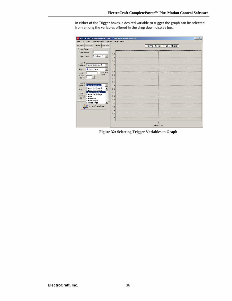
In either of the Trigger boxes, a desired variable to trigger the graph can be selected from among the variables offered in the drop down display box.
Figure 32: Selecting Trigger Variables to Graph
ElectroCraft CompletePower™ Plus Motion Control Software
ElectroCraft, Inc. 37
6.5 Zoom Feature
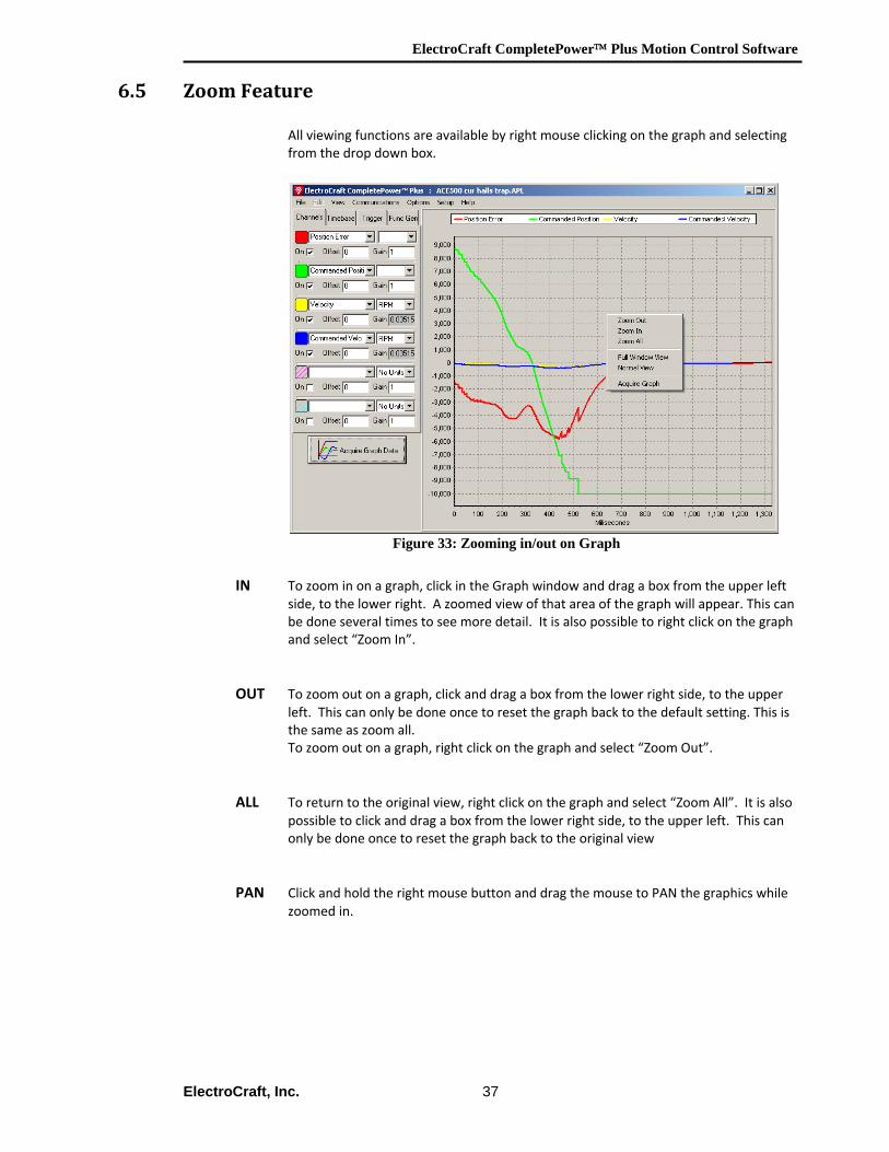
All viewing functions are available by right mouse clicking on the graph and selecting from the drop down box.
Figure 33: Zooming in/out on Graph
IN To zoom in on a graph, click in the Graph window and drag a box from the upper left side, to the lower right. A zoomed view of that area of the graph will appear. This can be done several times to see more detail. It is also possible to right click on the graph and select “Zoom In”.
OUT To zoom out on a graph, click and drag a box from the lower right side, to the upper left. This can only be done once to reset the graph back to the default setting. This is the same as zoom all. To zoom out on a graph, right click on the graph and select “Zoom Out”.
ALL To return to the original view, right click on the graph and select “Zoom All”. It is also possible to click and drag a box from the lower right side, to the upper left. This can only be done once to reset the graph back to the original view
PAN Click and hold the right mouse button and drag the mouse to PAN the graphics while
zoomed in.
ElectroCraft CompletePower™ Plus Motion Control Software
ElectroCraft, Inc. 38
6.6 Function Generator Tab
6.7 Function Generator Overview
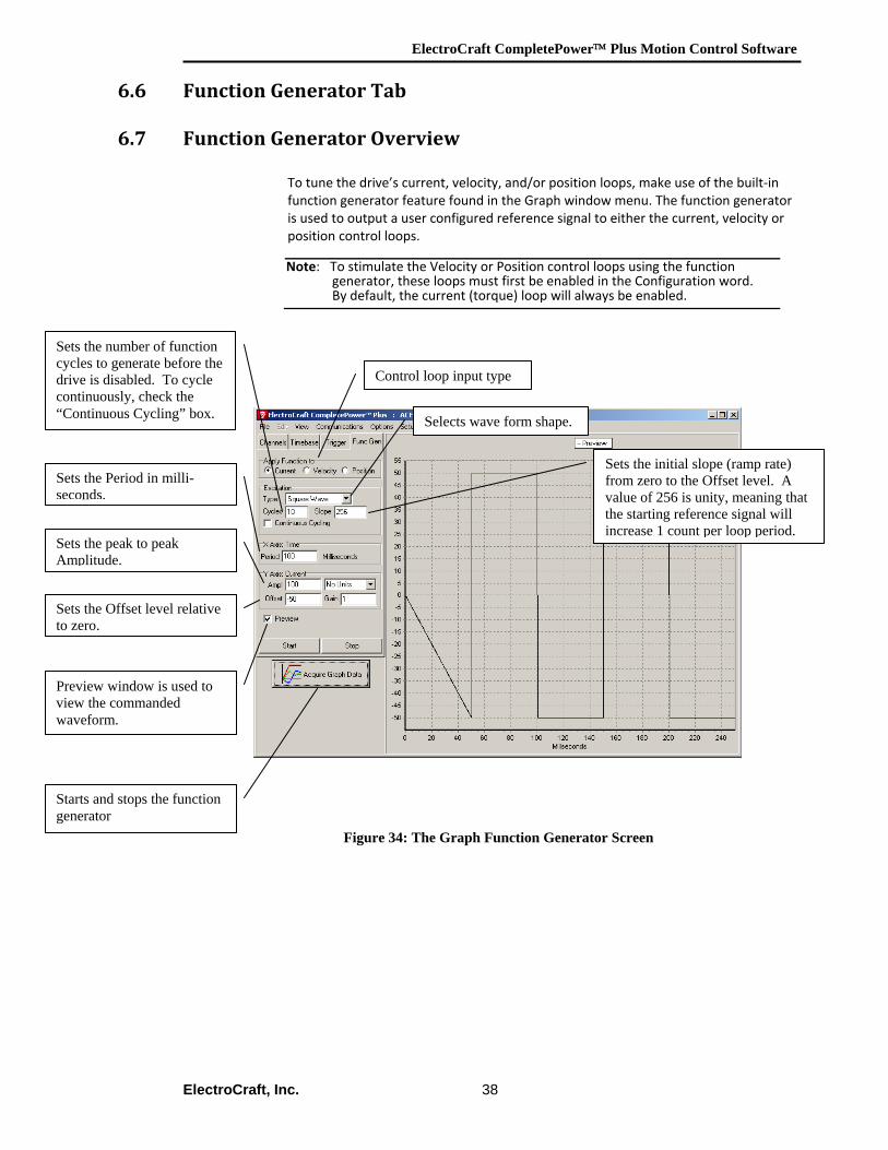
To tune the drive’s current, velocity, and/or position loops, make use of the built‐in function generator feature found in the Graph window menu. The function generator is used to output a user configured reference signal to either the current, velocity or position control loops.
Figure 34: The Graph Function Generator Screen
Note: To stimulate the Velocity or Position control loops using the function generator, these loops must first be enabled in the Configuration word. By default, the current (torque) loop will always be enabled.
Selects wave form shape.
Preview window is used to view the commanded waveform.
Sets the Period in milli-seconds.
Sets the peak to peak Amplitude.
Sets the Offset level relative to zero.
Sets the initial slope (ramp rate) from zero to the Offset level. A value of 256 is unity, meaning that the starting reference signal will increase 1 count per loop period.
Sets the number of function cycles to generate before the drive is disabled. To cycle continuously, check the “Continuous Cycling” box.
Control loop input type
Starts and stops the function generator
ElectroCraft CompletePower™ Plus Motion Control Software
ElectroCraft, Inc. 39
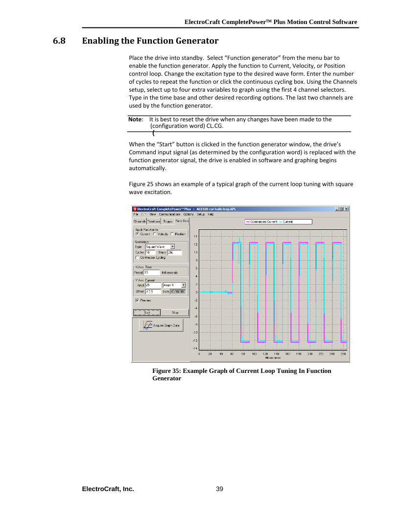
6.8 Enabling the Function Generator
Place the drive into standby. Select “Function generator” from the menu bar to enable the function generator. Apply the function to Current, Velocity, or Position control loop. Change the excitation type to the desired wave form. Enter the number of cycles to repeat the function or click the continuous cycling box. Using the Channels setup, select up to four extra variables to graph using the first 4 channel selectors. Type in the time base and other desired recording options. The last two channels are used by the function generator.
(
When the “Start” button is clicked in the function generator window, the drive’s Command input signal (as determined by the configuration word) is replaced with the function generator signal, the drive is enabled in software and graphing begins automatically.
Figure 25 shows an example of a typical graph of the current loop tuning with square wave excitation.
Figure 35: Example Graph of Current Loop Tuning In Function Generator
Note: It is best to reset the drive when any changes have been made to the (configuration word) CL.CG.
ElectroCraft CompletePower™ Plus Motion Control Software
ElectroCraft, Inc. 40
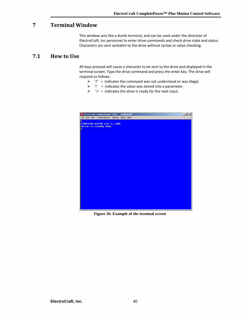
7 Terminal Window
This window acts like a dumb terminal, and can be used under the direction of ElectroCraft, Inc personnel to enter drive commands and check drive state and status. Characters are sent verbatim to the drive without syntax or value checking.
7.1 How to Use
All keys pressed will cause a character to be sent to the drive and displayed in the terminal screen. Type the drive command and press the enter key. The drive will respond as follows.
'?' = indicates the command was not understood or was illegal. '!' = indicates the value was stored into a parameter. '>' = indicates the drive is ready for the next input.
Figure 36: Example of the terminal screen