Embed Size (px)
Citation preview

1

2
FAG Industrial Services GmbHKaiserstraße 10052134 HerzogenrathGermanyTelephone: +49 (0) 2407 9149 66Fax: +49 (0) 2407 9149 59Email: [email protected] Webside: www.schaeffler.com/services
All rights reserved.No part of the documentation or software may be reproduced in any form or processed, duplicated or distributed usingelectronic systems without our written consent. We would like to point out that the designations and brand names of thevarious companies used in the documentation are generally protected by trademark, brand and patent laws.
Microsoft, Windows and Internet Explorer are brands or registered trademarks of the Microsoft Corporation in the USA and/orin other countries. Firefox is a trademark of the Mozilla Foundation.
The software uses the following third-party provider libraries under their respective licences:at91bootstrap, busybox, busybox-config, dropbear, expat, gdb, gettext, kexec-tools, kiss_fft, kmod, libcurl, libidn, libmodbus,libunwind, linuxFull licence conditions for the respective libraries can be found in the software's program directory.
Version 1.10.0Translation of the original user guide.© 15/07/2016 - FAG Industrial Services GmbH
Imprint

3
Contents
Contents
.......................................................................................................................................... 51 General.............................................................................................................................................................................................. 61.1 About this guide
.......................................................................................................................................... 72 Starting the software
.......................................................................................................................................... 93 The user interface at a glance.............................................................................................................................................................................................. 133.1 Updating the firmware
.............................................................................................................................................................................................. 143.2 Select device restart
.......................................................................................................................................... 164 Device Maintenance System.............................................................................................................................................................................................. 174.1 Update firmware
.............................................................................................................................................................................................. 194.2 Reset data partition
.............................................................................................................................................................................................. 194.3 Reset firmware
.............................................................................................................................................................................................. 194.4 Adjust system settings
...................................................................................................................................................................................... 19Edit system name 4.4.1
...................................................................................................................................................................................... 20Configure NTP server 4.4.2
...................................................................................................................................................................................... 21Change administrator password 4.4.3
...................................................................................................................................................................................... 21Configure IPv4 settings 4.4.4
...................................................................................................................................................................................... 22Configure IPv6 settings 4.4.5
...................................................................................................................................................................................... 23Replace server certificate (PEM) 4.4.6
.............................................................................................................................................................................................. 244.5 Download debug log files
.............................................................................................................................................................................................. 254.6 Open expert menu
...................................................................................................................................................................................... 26Reset administrator password 4.6.1
...................................................................................................................................................................................... 26Replace cryptographic keys 4.6.2
...................................................................................................................................................................................... 28Clear entire system 4.6.3
...................................................................................................................................................................................... 28Start remote access service 4.6.4
...................................................................................................................................................................................... 29Update Maintenance System 4.6.5
.............................................................................................................................................................................................. 304.7 Backup system
.............................................................................................................................................................................................. 314.8 Restore system
.............................................................................................................................................................................................. 334.9 Reboot system
.......................................................................................................................................... 345 Status.............................................................................................................................................................................................. 375.1 Creating/editing a message in the logbook
.......................................................................................................................................... 386 Measurement data.............................................................................................................................................................................................. 426.1 Edit alarm settings
.............................................................................................................................................................................................. 446.2 Download measurement data
.............................................................................................................................................................................................. 456.3 Delete measurement data
.......................................................................................................................................... 467 Live view
.......................................................................................................................................... 498 Configuration.............................................................................................................................................................................................. 508.1 Input configurations
...................................................................................................................................................................................... 51Internal sensors 8.1.1
...................................................................................................................................................................................... 52Analogue inputs 8.1.2
...................................................................................................................................................................................... 55Digital input 8.1.3
...................................................................................................................................................................................... 58Input with fixed value 8.1.4
.............................................................................................................................................................................................. 598.2 Measurement jobs
...................................................................................................................................................................................... 60Measurement jobs section 8.2.1
...................................................................................................................................................................................... 62Creating/editing new measurement jobs 8.2.2
...................................................................................................................................................................................... 64Available templates for measurement configurations 8.2.3
...................................................................................................................................................................................... 65Triggers and conditions 8.2.4
............................................................................................................................................................... 66Time trigger8.2.4.1
............................................................................................................................................................... 67Measurement trigger8.2.4.2
............................................................................................................................................................... 68Time condition8.2.4.3

4
............................................................................................................................................................... 69Measurement condition8.2.4.4
...................................................................................................................................................................................... 70Learning mode and alarm maps 8.2.5
.............................................................................................................................................................................................. 768.3 Output configurations
...................................................................................................................................................................................... 77Adding/editing output configurations 8.3.1
...................................................................................................................................................................................... 81Test output configuration 8.3.2
.............................................................................................................................................................................................. 828.4 Measurement trigger
...................................................................................................................................................................................... 83Adding/editing measurement trigger 8.4.1
.............................................................................................................................................................................................. 858.5 Measurement conditions
...................................................................................................................................................................................... 87Adding/editing measurement conditions 8.5.1
.............................................................................................................................................................................................. 888.6 External devices
...................................................................................................................................................................................... 89External devices section 8.6.1
...................................................................................................................................................................................... 91Adding/editing an external device 8.6.2
...................................................................................................................................................................................... 93Adding/editing an external input 8.6.3
...................................................................................................................................................................................... 94Creating/editing external outputs 8.6.4
...................................................................................................................................................................................... 97Integrating an external device into the system 8.6.5
............................................................................................................................................................... 98Mitsubishi GX Works2 software8.6.5.1
.............................................................................................................................................................................................. 1068.7 Device
...................................................................................................................................................................................... 106Device settings 8.7.1
...................................................................................................................................................................................... 109System time settings 8.7.2
.............................................................................................................................................................................................. 1108.8 Bearing
...................................................................................................................................................................................... 111Adding/editing bearings 8.8.1
.............................................................................................................................................................................................. 1138.9 Bearing manufacturer
.......................................................................................................................................... 1159 User management.............................................................................................................................................................................................. 1179.1 Adding/editing user group
.............................................................................................................................................................................................. 1189.2 Adding/editing users
.......................................................................................................................................... 11910 Manufacturer/support
.........................................................................................................................................................0Index

5
General
1 General
The FAG SmartWeb software offers you a user interface with which you can manage FAG SmartCheck. For example, youcan configure inputs and outputs, use a wizard to create measurement jobs for monitoring your machine, or verify thefunctions of the SmartCheck device. To be able to use the SmartWeb software, the SmartCheck device must beconnected to a computer.
About the FAG SmartCheck system
FAG SmartCheck is a vibration monitoring system for permanent frequency-selective monitoring. Measurement valuescan be captured, recorded and analysed using two integrated signals and up to three connected signals. After theanalysis, the system can switch outputs and display the status using LEDs depending on user-defined alarm limits.
Inputs are available, which record additional signals, to allow the device to be integrated into a superordinate system.These signals can be used as command variables for a dependent signal analysis, e.g. to initiate time or event-controlledmeasurement jobs.
The FAG SmartCheck device can be used to cover a wide range of applications; the SmartCheck device can be configuredto meet your own requirements using the integrated web application and FAG SmartWeb software. Multiple SmartCheckdevices can be combined in a network. Regardless of the number of devices, they can be managed centrally on a PCusing the FAG SmartUtility Light software. With the full version of FAG SmartUtility, you can also access the sensorsdirectly in the FAG SmartWeb software, analyse measurement data in the SmartUtility Viewer and downloadconfigurations and install them on other devices.
With FAG SmartCheck, Schaeffler offers status monitoring that is optimised to suit your requirements.

6
1.1 About this guide
This guide describes how to use the FAG SmartWeb software. Read this guide carefully before using the software, andstore it in a safe place.
Make sure that
This guide is available to all users
If the product is passed on to other users, that this guide is also passed on with it
Additions and amendments provided by the manufacturer are always attached to this guide.
Further information
This software is an integral part of the FAG SmartCheck vibration monitoring system. This system also includes the FAGSmartCheck device and the FAG SmartUtility Light software, each of which is described in its respective manual.
Optionally, instead of the FAG SmartUtility Light software, you can purchase the FAG SmartUtility software withenhanced functionality. This is also described in a separate manual.
Definitions
Product: the FAG SmartWeb software described in this manual.
User: person or organisation capable of putting the product into operation and using it.
Symbols used
This symbol indicates
Helpful additional information and
Device settings or practical tips that will help you to perform activities more efficiently.
Cross-reference symbol : this symbol refers to a page in the manual that provides further information. If you arereading the manual in PDF format on a screen, clicking the word to the left of the cross-reference symbol will take youstraight to the section in question.
119
6

7
Starting the software
2 Starting the software
Perform a firmware update before commissioning. You can download the latest version via the SmartUtility software or from the SmartCheck microsite www.fag-smartcheck.com.
Only start the SmartWeb software after ensuring the following:
The FAG SmartCheck device is connected to the Ethernet network.
The FAG SmartCheck device is supplied with power.
The FAG SmartCheck device has finished loading and starting and is in measuring mode.
Details on how to connect and start the <var styleclass="Normal">FAG SmartCheck</var> can be found in the FAGSmartCheck user documentation.
The FAG SmartWeb software can be started in two different ways:
Start with IP address in the browser
The SmartCheck device is delivered with the default IP address 192.168.1.100. Enter this IP address in the address fieldof your browser:
Press the Enter key to start the SmartWeb software.
Start via the FAG SmartUtility software
The SmartUtility software, which you can optionally purchase, can be used to search for and open SmartCheck deviceswith wizard support. In doing so, the SmartWeb software opens in a separate tab of your browser for each device. Youwill find details on this in the manual for the SmartUtility software.
Also for this option, the SmartCheck device must be connected to the Ethernet network and supplied with power.
If you cannot adapt the IP address field on your computer to the default IP address of the<var styleclass="Hint">FAG SmartCheck</var> device, you will need to change the IPaddress of the FAG SmartCheck device. This is possible both with the FAG SmartUtility Lightsoftware included in the scope of delivery and with the optional FAG SmartUtility software.Details on this can be found in the respective user documentation.
If you are using a proxy server between the browser and the internet in your companynetwork, you will need to adjust your browser's internet settings accordingly. To do so, go toInternet Explorer and enter the address and port number of the proxy server under Tools >Internet options. Please contact your system administrator for more detailed informationabout proxy settings.
Once the SmartWeb software is started, the system time of the SmartCheck device iscompared with the computer time. The system time can be adjusted if required.
The SmartWeb software checks on a regular basis whether SmartUtility has newconfigurations. If so, the page is reloaded.
If an SmartCheck device cannot be opened in the browser, clear the browser cache and tryagain.
If you receive the message stating that cookies are not accepted, please allow the use ofcookies or enter the IP address of the SmartCheck device as an exception.
If you are working on a computer with several SmartCheck devices, these devices should haveidentical firmware versions installed. If different firmware versions are installed, this can haveundesired effects within the browser.
Start message
After starting the FAG SmartWeb software, first you see the start message. This informs you of the preconfiguredsettings of your FAG SmartCheck device:
Analogue input 1: Voltage input [0–10 V], signal "voltage [0–10 V]"
Analogue input 2: Current input [0–20 mA], signal "load [0–100 %]"
Digital input: Speed input, signal threshold "7 V"
"Machine is running" measurement condition: Based on vibration values
109

8
Base measurement job
It also informs you of important points to note when starting the SmartCheck for the first time:
Change the program language under Edit > Edit program settings .
Familiarise yourself with the SmartCheck device, e.g. by opening the Live view area and knocking or shaking toactivate the vibration sensor. The measurement results are shown directly in the display.
Change the preconfigured settings in the Configuration area. This applies in particular for the "Machine isrunning" measurement condition , because this is based on vibration values, whereas the engine speed is abetter criterion in many environments.
In the area Configuration > Measurement jobs , create new measurement jobs using the wizard.
Select the option Do not show this message again, if you do not want the start message to appear the next time youstart the software. You can change these settings at any time under Edit > Edit program settings > Messages.
10
46
49
86
59

9
The user interface at a glance
3 The user interface at a glance
If the browser window is closed by mistake or the connection to the SmartCheck device isinterrupted, any settings that you have not yet confirmed with OK will be lost. Consequently,always check whether the last change you made via the user interface of the software hasactually been adopted.
If you do not make any changes for more than an hour in the SmartWeb software, you areautomatically logged out.
The user interface of the FAG SmartWeb software can be divided as follows:
The user interface offers you these options:
Title bar
The following information can be found in the right-hand corner or the title bar:
Connected to: Here you will find the name of the SmartCheck device.
Logged in as: Here you will find the user name under which you are currently logged in.
: This symbol indicates which status the "Machine is running" measurement condition has identified for themachine. Under Measurement conditions , you can set the criteria for the "Machine is running"measurement condition for your machine. Depending on the status determined, the following symbol isdisplayed:
: the "Machine is running" measurement condition is fulfilled: the machine is in operation.
: the "Machine is running" measurement condition is not fulfilled: the machine is not in operation.
: If this symbol is visible, at least one characteristic value is in learning mode.
: The square symbol shows you the alarm status of the SmartCheck device; the symbol is displayed indifferent colours according to the status:
Grey: No characteristic value has yet been measured.
Green: No alarm exists.
Yellow: One or several characteristic values have triggered a pre-alarm.
86

10
Red: One or several characteristic values have triggered a main alarm.
Alternating between grey and green: Learning mode is active for one of your measurement jobs.If a pre-alarm or main alarm is triggered during the learning process, the alarm symbol indicates therelevant alarm status without flashing, i.e. it lights up permanently in yellow or red.
Menu bar
The following options can be found in the menus:
File Print page: This command prints the current view of the SmartWebsoftware. Ensure that you have selected the option for page setup in yourbrowser such that the page is reduced to fit the page size when printing.
Find the corresponding option e.g. in Mozilla Firefox (Shrink to fit PageWidth) and also in Windows Internet Explorer (Enable Shrink-to-Fit)under File > Page Setup.
Log out: Use this command to log out of the SmartCheck device. Theconnection to the device is closed.
Edit The functions available in the Edit menu depend on your user rights. Undercertain circumstances, some functions are deactivated because you do nothave the authorisations for them.
Change password: This command opens the corresponding area inthe SmartWeb software. You can then change your password or thepassword of the logged-in user.
User management: With each of the commands in this submenu, thecorresponding area in the SmartWeb software opens. You can thenmake your changes.
Device settings: With each of the commands in this submenu, thecorresponding area in the SmartWeb software opens. You can thenmake your changes.
Create new measurement job: This command starts a wizard thatguides you through creating a new measurement job .
Edit program settings: Here you can specify the following:
Units: Determine the system of units that the SmartWeb software shoulduse. Among other things, this setting affects the dialogues in which youmust select a unit.- With ISO, international units are displayed, e.g. mm/s.- With US, American units are displayed, e.g. mil/s.- With All, both international and American units are displayed, e.g. mm/sand mil/s.
Language: When possible, the SmartWeb software is automaticallylaunched in the language that you have set for your browser. Here youcan manually set the language in which the interface of the SmartWebsoftware is displayed.The following languages are available:
Language Language Idioma Langue Hànyu
German English Spanish French Chinese
Messages: The software provides you with information at various pointsusing automatic messages. You can switch off each automatic messageusing the option Do not show this message again. Here, you canswitch the automatic messages back on again for selected messages.
Measurement data Open measurement data display: Use this command to go to theMeasurement data area.
Download measurement data: Use this command to open a dialogue inwhich you can select measurement data for download .
Delete measurement data: Use this command to open a dialogue inwhich you can select measurement data for deletion .
Go to With the commands in this menu, you can switch to those areas that you canalso control via the buttons under Areas, i.e. to Status , Measurement data
, Live view , Configuration and User Management .
115
115
106
62
38
44
45
34
38 46 49 115

11
The user interface at a glance
Help Open Help: Use this command to open a link to the website of theSmartCheck device. You can open the SmartWeb Help from there underDownloads.
Update firmware : Use this command to open a dialogue in which youcan update the firmware.
Select device restart : Use this command to open a dialogue in whichyou can reset or restart the device. Using this dialog, you can also open the Maintenance System of the device or reset the data partition.
Version information: Use this command to open a window with detailedinformation on the version of the SmartCheck device, including factoryfirmware, device ID and serial number.
The settings for units, language, and messages are stored as cookies. When you deletecookies, these settings are also deleted in the SmartWeb software. Next time the SmartWebsoftware starts, it will be using the pre-set units and the language set for your browser again.Automatic messages are displayed again by default.
The language setting is also influenced by the FAG SmartUtility software: If you open theSmartWeb software via the <var styleclass="Hint">SmartUtility</var> software, the languagesetting from the SmartUtility software is used.
Areas
These buttons take you to the different areas of the SmartWeb software. You can also log out of theSmartCheck device here:
Status: Detailed information on the system and on the status of the measurement jobs andtheir characteristic values can be found here. You can see at a glance which characteristicvalues have triggered an alarm and follow the activities of the SmartCheck device in themessages of the logbook.
Measurement data: The measurement data for specific characteristic values can bedisplayed in this area. The display includes trends, time signals and spectral data.
Live view: The signals of the configured inputs can be displayed here in real time.
Configuration: This area is particularly significant when setting a new SmartCheck device:This is where you create measurement jobs, configure inputs and outputs, make basic devicesettings, and edit the databases for bearings and bearing manufacturers.
User management: Here you can create, delete and manage users and user groups, aswell as change your password or the password of the user currently logged in. In addition, youwill find in this area the functions for activating and deactivating user management.
Log out: Click on this button to log out of the SmartCheck device and close the SmartWebsoftware.
Actions
Here you will find the selected important actions, which are either possible in the current area or lead toanother area as a link. For example, if you have opened the Measurement data area, you will find thefollowing commands here: Show measurement jobs, Download measurement data and Deletemeasurement data.
Items of the selected area
What you see here depends on the current area. For example, if you have opened the Configuration area,you can select individual configuration items - such as Measurement Jobs or Measurement Conditions -here and then view information about them in the main panel of the SmartWeb software and make furtheredits.
Detailed information and editing functions for the selected items
If you have selected an item on the left, you will see detailed information on it in the main panel of theSmartWeb software and can make further edits. What exactly is possible depends on your particular selection.
13
14
34
38
46
49
115

12
Status bar
The status bar informs you e.g. whether your browser has already finished loading the selected new area.
You can use the separator between the overview columns on the left and the main panel on theright to adapt the interface of the SmartWeb software to suit your requirements:
Holding down the left mouse button, drag the separator to the left or the right to alter thesize of the respective surface.
Click on the separator to hide the overview columns on the left. This enlarges the main panelto fill the full screen width. Click again on the separator to restore the view.
At many points in the interface, items are displayed in a tree structure. To see subordinateitems, click on ; to hide them again, click on .
In some areas of the SmartWeb software, the information is presented in tables. You canstructure tables using the following functions:
Columns as sort criteria: Set any column of a table as a sort criterion by clicking in thecolumn title. Click a second time to change the sort order, i.e. from ascending to descendingor vice-versa. The current sort order is displayed by the symbols for ascending and fordescending.
Move columns: Move any column to another position in the table. To do this, click with theleft mouse button in the column title and hold down the mouse button. Then drag the cursorto the position in the table you want the column to appear in future.

13
The user interface at a glance
3.1 Updating the firmware
How to update the firmware
1. From the Help menu, select the Update firmware option in order to open the corresponding window:
2. Click Search to search for and select the firmware file.
3. Click OK to update the SmartCheck device with the selected firmware. Click Cancel to close the window withoutapplying any changes.
When the firmware is updated, all measurement data and configurations on the device maybe lost. Before updating, save everything by downloading measurement data and, ifapplicable, configurations with the SmartUtility software. The taught-in alarm limits are part ofthe configuration and are downloaded at the same time.
The update can take several minutes. The status LED on your SmartCheck device will flashyellow and red alternately during this time. The following is very important in this process:
o The power supply to the SmartCheck device must not be interrupted.
o The Ethernet connection to the SmartCheck device must not be interrupted.
o The update must be fully completed.
The device is no longer functional if these conditions are not met!
If a serious error occurs during a firmware update, the device is reset to the factory firmware.You can find the version of your factory firmware under Help > Version information.
After you have performed the firmware update, empty the browser cache. This is necessary toensure that the latest version of the FAG SmartWeb software is loaded in your browser.
14
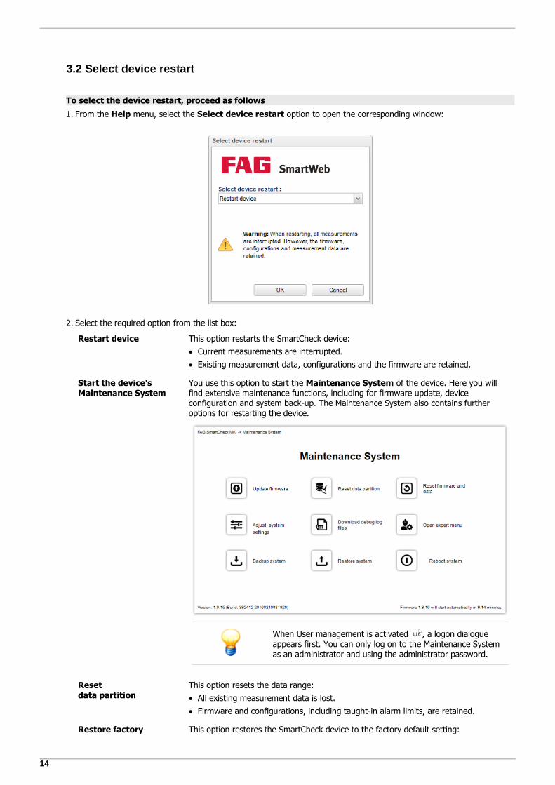
3.2 Select device restart
To select the device restart, proceed as follows
1. From the Help menu, select the Select device restart option to open the corresponding window:
2. Select the required option from the list box:
Restart device This option restarts the SmartCheck device:
Current measurements are interrupted.
Existing measurement data, configurations and the firmware are retained.
Start the device'sMaintenance System
You use this option to start the Maintenance System of the device. Here you willfind extensive maintenance functions, including for firmware update, deviceconfiguration and system back-up. The Maintenance System also contains furtheroptions for restarting the device.
When User management is activated , a logon dialogueappears first. You can only log on to the Maintenance Systemas an administrator and using the administrator password.
Reset data partition
This option resets the data range:
All existing measurement data is lost.
Firmware and configurations, including taught-in alarm limits, are retained.
Restore factory This option restores the SmartCheck device to the factory default setting:
116

15
The user interface at a glance
default setting All existing measurement data is lost.
All taught-in alarm limits are deleted.
All configurations are lost.
The firmware is reset to the factory default firmware.
To save measurement data, taught-in alarm limits and configurations, download themeasurement data and configurations with the SmartUtility software before yourestore the factory default setting. The taught-in alarm limits are part of theconfiguration and are downloaded at the same time.
3. Click OK to reset the SmartCheck device with the selected option. Click Cancel to close the window without applyingany changes.
Once the factory default setting has been restored, the SmartCheck behaves as follows:
The device then tries to obtain an IP address via DHCP.
If the device does not receive an address, it reverts to address 192.168.1.100/24.
Ensure that the device is accessible and then install the latest firmware.

16
4 Device Maintenance System
The Maintenance System of the FAG SmartCheck device offers comprehensive maintenance functions. You can use thissystem, for example, to update the firmware, configure the SmartCheck device, to back up a system, or to restore asystem from back-up. You can also use the latter function to duplicate devices. The Maintenance System also offers securely protected expert functions for updating the Maintenance System or for deleting the entire system on aSmartCheck device among other things.
The Maintenance System is independent of the actual firmware on the device and can also be accessed via the browser,for example, if a firmware update has not run correctly.
To open the Maintenance System of the SmartCheck device, proceed as follows:
1. From the Help menu, select the Select device restart option to open the corresponding window:
2. From the selection list, choose the option Start the device's Maintenance System.
3. Click on OK. The log-in page for the Maintenance System is displayed:
4. Click on the button Login to open the start page of the Maintenance System. Use the button Expert Menu todirectly access the Expert menu .If user management is activated in the SmartCheck firmware, a log-in dialogue appears in which you are required to
25

17
Device Maintenance System
log in as an administrator using the administrator password. If user management is deactivated, the start page opensdirectly:
5. On the start page, click on an icon to select the relevant function. Depending on the function you choose, you willthen need to perform further steps or select sub-functions in a submenu. For information on the individual functions ofthe Maintenance System, see the following sections.
If the Maintenance System is started, the SmartCheck device interrupts all measurements.
If you have opened a function of the Maintenance System, the Homepage button isdisplayed at the top right. Click on this button to return to the start page of the MaintenanceSystem.
The Maintenance System has a timer function: if you do not make any changes for a certainperiod of time, the device is automatically restarted. The length of time depends on whereyou are in the Maintenance System:
Login page of the Maintenance System: restart after 2 minutes
Start page of the Maintenance System and all function pages: restart after 10 minutes
Login page of the expert menu Expert Menu: 60 minutes
The remaining time until the device restarts is always displayed at the bottom right.
4.1 Update firmware
Click on the Update firmware button to start this function. You can update your system with a new firmwareversion here. This does not delete the measurement data.
Depending on the version of your firmware, you can also use this function to downgrade to aprevious firmware version. In this case, the measurement data is also deleted.
The option to downgrade is available as follows:
Up to release 1.10.0: Downgrade to previous versions is possible
From release 1.10.0 and above: Downgrade is only possible to 1.10.0

18
How to update the firmware
1. Click on the Select file button and search for the SF2 file containing the required firmware.
2. Open the SF2 file. The system analyses the file and informs you whether the update is possible, and if yes, whichfirmware will be installed:
If the selected file is not a valid firmware file, you will be informed of this too.
3. Click on the OK button to start the update.
When the firmware is updated, all measurement data and, in some cases, also theconfigurations on the device are lost. Before updating, save everything by downloadingmeasurement data and, if applicable, configurations with the SmartUtility software. Thetaught-in alarm limits are part of the configuration and are downloaded at the same time.
The update can take several minutes. The status LED on your SmartCheck device will flashyellow and red alternately during this time. The following is very important in this process:
o The power supply to the SmartCheck device must not be interrupted.
o The Ethernet connection to the SmartCheck device must not be interrupted.
o The update must be fully completed.
The device is no longer functional if these conditions are not met!
If a serious error occurs during a firmware update, the device is reset to the factory firmware.You can find the version of your factory firmware under Help > Version information.
After you have performed the firmware update, empty the browser cache. This is necessary toensure that the latest version of the FAG SmartWeb software is loaded in your browser.
19
Device Maintenance System
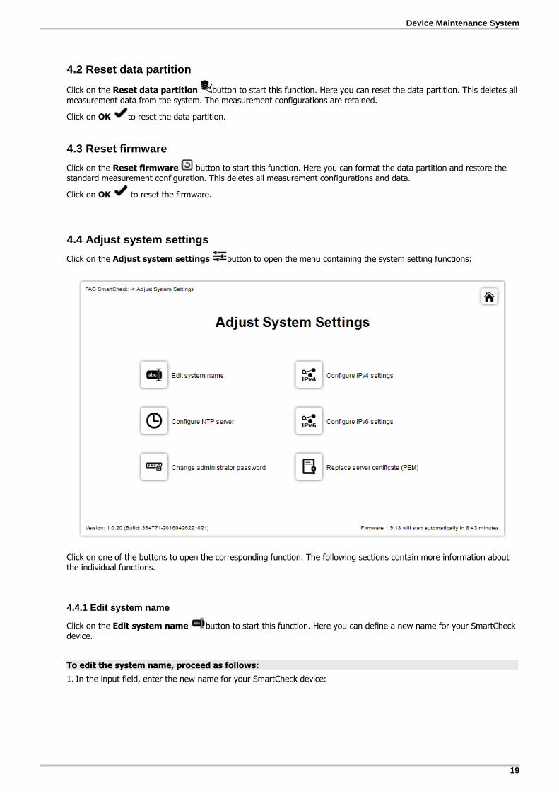
4.2 Reset data partition
Click on the Reset data partition button to start this function. Here you can reset the data partition. This deletes allmeasurement data from the system. The measurement configurations are retained.
Click on OK to reset the data partition.
4.3 Reset firmware
Click on the Reset firmware button to start this function. Here you can format the data partition and restore thestandard measurement configuration. This deletes all measurement configurations and data.
Click on OK to reset the firmware.
4.4 Adjust system settings
Click on the Adjust system settings button to open the menu containing the system setting functions:
Click on one of the buttons to open the corresponding function. The following sections contain more information aboutthe individual functions.
4.4.1 Edit system name
Click on the Edit system name button to start this function. Here you can define a new name for your SmartCheckdevice.
To edit the system name, proceed as follows:
1. In the input field, enter the new name for your SmartCheck device:

20
2. Click on OK to confirm the name.
4.4.2 Configure NTP server
Click on the Configure NTP server button to start this function. Here you can define an NTP server from which theSmartCheck device can obtain the system time.
To configure the NTP server, proceed as follows:
1. In the input field, enter the IP address or server name of the NTP server:
21
Device Maintenance System
2. Click on OK to confirm the IP address or server name.
If the system time is based on an NTP server, synchronization runs constantly. For this method,therefore, the SmartCheck device must have a permanent connection to the network, and theNTP server must always be accessible.
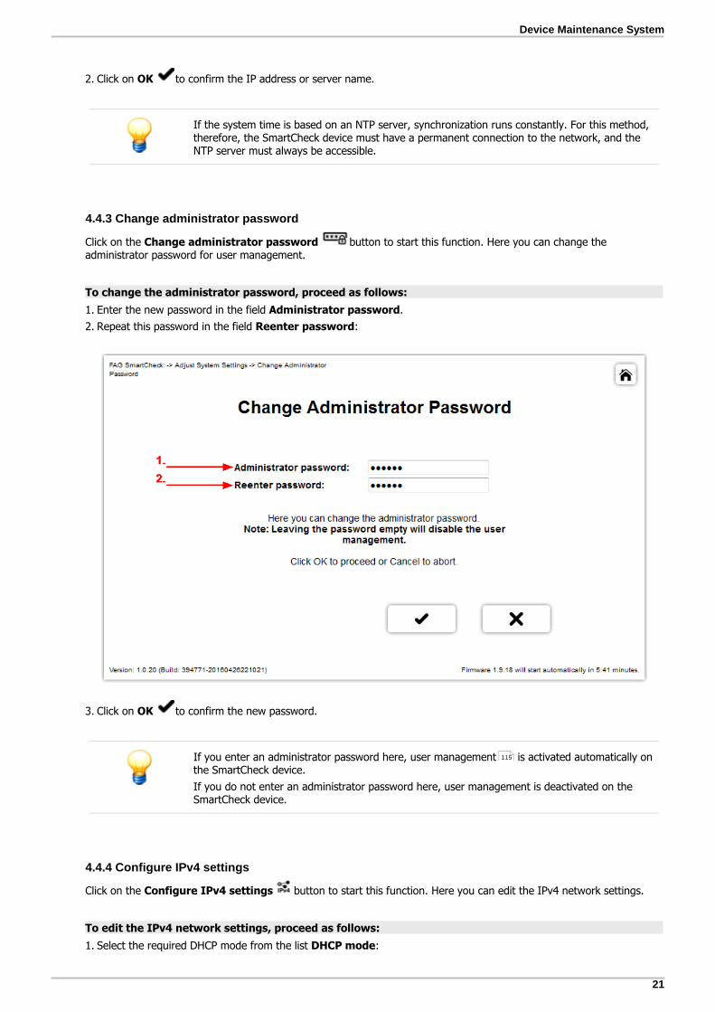
4.4.3 Change administrator password
Click on the Change administrator password button to start this function. Here you can change theadministrator password for user management.
To change the administrator password, proceed as follows:
1. Enter the new password in the field Administrator password.
2. Repeat this password in the field Reenter password:
3. Click on OK to confirm the new password.
If you enter an administrator password here, user management is activated automatically onthe SmartCheck device.
If you do not enter an administrator password here, user management is deactivated on theSmartCheck device.
4.4.4 Configure IPv4 settings
Click on the Configure IPv4 settings button to start this function. Here you can edit the IPv4 network settings.
To edit the IPv4 network settings, proceed as follows:
1. Select the required DHCP mode from the list DHCP mode:
115

22
You have the following options:
No DHCP With this option, you can specify the IPv4 address or continue to use the defaultIP address of the SmartCheck device.
If No DHCP is activated, you must also specify the other settings in this step,e.g. IP address, Netmask or Gateway.
DHCP: Send host name toserver
With this option, the SmartCheck device automatically receives an IP addresswithin your network. The host name is registered by the SmartCheck device in thenetwork's DNS server.
DHCP: Load host name fromserver
With this option, the SmartCheck device automatically receives an IP addresswithin your network. The host name is specified via the network's DNS server.
2. Depending on the selection for DHCP mode, you will need to make further entries under Host name, IP address,Netmask, Gateway , or Name server.
3. Click on OK to confirm the changes and return to the system settings menu.
If you change the IP address of the SmartCheckGeräts, you no longer have access to theSmartWeb software under the previous address. You must then enter the new address of thedevice in the browser in order to load the software and the Maintenance System again.
If the IP address is allocated automatically via DHCP, the SmartCheck device can only beaccessed via the automatically allocated IP address or using the host name (DNS). You can nolonger use the default IP address.
4.4.5 Configure IPv6 settings
Click on the Configure IPv6 settings button to start this function. Here you can edit the IPv6 network settings.
To edit the IPv6 network settings, proceed as follows:
1. Select the required DHCP mode from the list DHCP mode:

23
Device Maintenance System
You have the following options:
No DHCP With this option, you can specify the IPv6 address or continue to use the defaultIP address of the SmartCheck device.
If No DHCP is activated, you must also specify the other settings in this step,e.g. IP address, Netmask or Gateway.
DHCP: Load host name fromserver
With this option, the SmartCheck device automatically receives an IP addresswithin your network. The host name is specified via the network's DNS server.
2. Depending on the selection for DHCP mode, you will need to make further entries under IP address, Netmask,Gateway or Name server.
3. Click on OK to confirm the changes and return to the system settings menu.
If you change the IP address of the SmartCheckGeräts, you no longer have access to theSmartWeb software under the previous address. You must then enter the new address in thebrowser in order to load the software again.
If the IP address is allocated automatically via DHCP, the SmartCheck device can only beaccessed via the automatically allocated IP address or using the host name (DNS). You can nolonger use the default IP address.
4.4.6 Replace server certificate (PEM)
Click on the Replace server certificate (PEM) button to start this function. Server certificates are used forauthentication of the server by the client. Here you can replace the server certificate that is defined on the SmartCheckdevice with your own server certificate.
To replace the server certificate of the SmartCheck device, proceed as follows:
1. Click on the button Server certificate file and search for the PEM file containing the required server certificate.
2. Open the PEM file and, if necessary, enter the password for the PEM file in the field Passphrase:

24
3. Click on OK to upload the certificate. The system analyses the file and informs you if can install the file:
If the file does not contain a valid server certificate, you will be informed of this too.
4. Click on OK to install the server certificate.
4.5 Download debug log files
Click on the Download debug log files button to start this function. Here you can create and download an errorlog file. You cannot view this file yourself. You need to send it to our Support Team where it can be analysed.119

25
Device Maintenance System
To download the log files, proceed as follows:
1. Click on OK to start the action.
2. The error log file is downloaded. A progress bar informs you of the download progress.
3. Your browser prompts you to save the file. Confirm this. You can then find the error log file *.SCLG in the standarddownload folder.
4.6 Open expert menu
Click on the Open expert menu button to start the secure log-in process for the expert menu.
The expert menu contains functions that you can use to change the basic settings of the FAG SmartCheck device.Because these are system-critical settings, the expert menu can only be opened via the secure log-in process with asingle-use password. The following section contains information about the secure log-in process.
To perform the secure log-in process, proceed as follows:
1. On the start page of the log-in process, you will find an ID. Share this ID with our support team , e.g. by e-mail ortelephone.
2. Our support team will use this ID to generate a single-use password and will forward this to you.
3. Click on the Login button to open the authentication page, and enter the user name in the User Name field andthe single-use password in the Password field:
4. Click on the OK button. The expert menu home page is displayed:
119

26
Click on one of the buttons to open the corresponding function. The following sections contain more information aboutthe individual functions in the expert menu.
The ID and the single-use password are only valid while you remain in the maintenancesystem. As soon as you restart the SmartCheck device, the ID and password are no longervalid. When you restart the maintenance system, a new ID then becomes valid, and you canuse this to request a new password from support.
On the homepage for the log-in process, you have 60 minutes to obtain the single-use
password from support. During this time, if you use the button to switch to themaintenance system and from there back to the home page of the log-in process, the timer isreset to 60 minutes.
4.6.1 Reset administrator password
Click on the Reset administrator password button to start this function. Here you can reset the administratorpassword to the factory default setting. All users can then log on without a password and have administrator rights. Thisdeactivates user management.
Click on OK to reset the administrator password.
Use the Change administrator password function to change the administrator password.To find this function, choose Adjust system settings in the main menu of the MaintenanceSystem.
4.6.2 Replace cryptographic keys
Click on the Replace cryptographic keys button to start this function. The cryptographic keys are used to decodefirmware files (*. SF2) and back-up files (*.SCBK) and for encoding back-up and protocol files. If they have becomeknown due to a cyber attack, they must be replaced. This ensures that no harmful software can be installed on thesystem.
21

27
Device Maintenance System
To replace the cryptographic keys, proceed as follows:
1. Click on the button Keystore and search for the file containing the cryptographic keys.
2. Open the file:
3. Click on OK to upload the cryptographic keys. The system analyses the file and informs you if can install the file:
If the file does not contain any valid cryptographic keys, you will be informed of this too.
4. Click on OK to install the new cryptographic keys.

28
4.6.3 Clear entire system
Click on the Clear entire system button to start this function. Here you can delete the entire system includingfirmware, configurations and measurement data. The Maintenance System remains unaffected by this function.
1. Click on OK to delete the entire system. The system is deleted and you then receive the following message:
2. You must now install new firmware. You also need to reconfigure the IP address of the SmartCheck device, because ithas been reset to the standard IP address by this action.
After you have used the action Clear entire system, no firmware is available on theSmartCheck device. You have the following options to continue working with the device:
Load a new firmware file onto the device using Update firmware .
Choose Restore system to load a previously created back-up file containing the entiresystem onto the device.
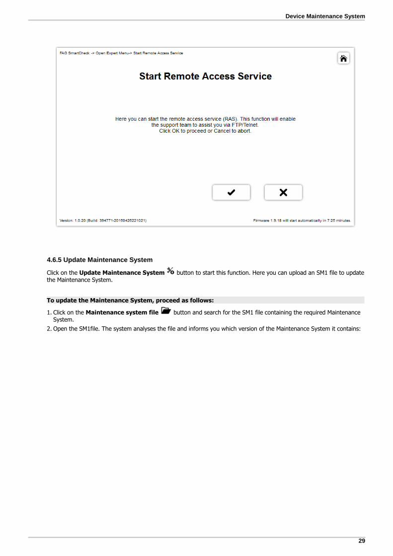
4.6.4 Start remote access service
Click on the Start remote access service button to start this function. Using this function, our Support Teamcan support you via an FTP/Telnet server in the Maintenance System. As soon as you restart the SmartCheck device, theRemote Access Service (RAS) is terminated.
To start remote access via RAS, proceed as follows:
1. Click on OK to start remote access via RAS.
2. The system reports that RAS has started successfully:
17
31
119
29
Device Maintenance System
4.6.5 Update Maintenance System
Click on the Update Maintenance System button to start this function. Here you can upload an SM1 file to updatethe Maintenance System.
To update the Maintenance System, proceed as follows:
1. Click on the Maintenance system file button and search for the SM1 file containing the required MaintenanceSystem.
2. Open the SM1file. The system analyses the file and informs you which version of the Maintenance System it contains:

30
If the selected file does not contain a Maintenance System, you will be informed of this too.
3. Click on OK to update the Maintenance System.
For this function, ensure a functioning power supply and an uninterrupted connection to theSmartCheck device. If problems occur during the update, send the device to our support team
.
4.7 Backup system
Click on the Backup system button to start this function. Here you can create a back-up file of your system inorder to save firmware, configurations and data. You can then use the Restore system function to select and loada back-up file to restore a system, or to duplicate devices, e.g. to load configurations on multiple SmartCheck devices.
To back up your system, proceed as follows:
1. Select the required back-up type from the selection list:
119
31

31
Device Maintenance System
You have the following options:
Firmware withconfigurations(without data)
You can use this option to save the firmware and the configurations of the system.The measurement data is not saved.
Firmware withconfigurations and data
You can use this option to save the firmware, configurations and measurement dataof the system.
2. Click on OK to confirm the selected type of back-up and start the action.
3. The back-up file is downloaded. A progress bar informs you of the progress.
4. Your browser prompts you to save the file. Confirm this prompt. You can then find the back-up file *.SCBK in thestandard download folder.
Depending on the data volume, if you use the option Firmware with configurations anddata the file can become very large and the download therefore may take a long time. Duringthe download, the timer function is repeatedly reset to 10 minutes and does not expire.
4.8 Restore system
Click on the button Restore system to start this function. Here you can select a previously created back-up fileto restore a system. The back-up file either contains only the firmware and configurations, or it contains the entiresystem (firmware, configurations, and data). A back-up file can, for example, be loaded to a new SmartCheck device thatwill replace a previous device. In addition, you can also use a back-up file to copy a particular system to multiple devices.
To restore the system, proceed as follows:
1. Click on the Select file button and search for the SCBK file containing the required system.
2. Open the SCBK file. The system analyses the file and informs you which firmware the selected file contains:
30

32
If the selected file is not a valid back-up file, you will be informed of this too.
3. Click the OK button. You will then be prompted to enter more precise details for restoring the system:
You have the following options:
Replacement unit Select this option if you want to use the back-up file to load the system to areplacement unit. If the selected back-up file also contains measurement data, theoption Restore measurement data too also appears (see below).
Additional unit Select this option if you want to use the back-up file to copy the firmware and theconfigurations to other SmartCheck devices.

33
Device Maintenance System
Restore measurementdata too
This option is only displayed
if the selected back-up file also contains measurement data (in addition to thefirmware and configurations) and
if you have selected the option Replacement unit.
Select this option to also restore the measurement data of the back-up file. Bydefault, this option is deactivated and the system is restored without measurementdata.
4. Click on OK to confirm your selection and to start restoration of the system.
If the Restore System function is cancelled after it has been started, there will no longer beany firmware on the SmartCheck device. When you start the SmartCheck device, theMaintenance System opens. You must then load new firmware onto the device, for example,using the functions Update firmware or Restore system.
When you create a back-up file, not all content is copied. A back-up file for instance does notcontain a network address. If you use Restore system to load a back-up file onto a newdevice, the network address of the new device is retained.
4.9 Reboot system
Click on the Reboot system button to start this function. This function enables you to shut down and restart thesystem. This shortens the time until the automatic restart specified by the timer function of the Maintenance System .
Click on OK to confirm the restart.
This function is available both on the start page of the Maintenance System and in the expertmenu.
17

34
5 Status
Click on the Status button to open the corresponding area. Here you will find a general overview of the status ofthe SmartCheck device:
You can find the following information here:
Status and context menu
Your measurement jobs and the corresponding characteristic values are listed here. The alarm symbols showyou at a glance:
Non-critical measurement job
Measurement job with pre-alarm
Measurement job with main alarm
Non-critical characteristic value
Characteristic value with pre-alarm
Characteristic value with main alarm
Characteristic value without measured values
Sensor fault
To see the status of a characteristic value in the main panel of the area, click on the desired characteristicvalue.
For each item in this list, you can right-click to open a context menu, where you will find the followingcommands:
Reset alarmFor individual characteristic values: Switch off the alarm for this characteristic value manually here. Thisoption is required if alarms for this measurement job are not automatically reset as soon as the measuredvalue drops below the alarm limit.

35
Status
Reset all alarmsFor individual measurement jobs: Manually switch off the alarms of all subordinate items here.
You can only reset alarms manually, e.g. via this context menu, if you made the correspondingsetting when creating or editing a measurement job in the Set Alarms step: under ResetAlarms, you must activate the Manual option.
Alarm settingsFor individual characteristic values: Here you open a dialogue in which you can view and edit the alarmsettings for this characteristic value.
Start learning modeFor individual characteristic values: Start the learning mode for the selected characteristic value again here.Details on the learning mode and how it works can be found here .
Start learning mode for allFor individual measurement jobs: Start the learning mode again for all subordinate items for which thelearning mode is authorised. Details on the learning mode and how it works can be found here .
Live viewFor individual characteristic values: Switch here to the Live view area. There you will see in real timethe signal used for the calculation of this characteristic value.
Measurement dataSwitch here to the Measurement data area. There you can display the trends and time signals ofthese measurement jobs/this characteristic value and carry out an initial analysis.
The commands available depend on which level in the tree structure the selected item is located and whetheryou have the user rights for the desired action.
Actions
In this area, you will find the menu items Create new measurement job and Show measurementjobs . They allow you to create a new measurement job and to go straight to the detailed overview of yourmeasurement jobs via the corresponding wizards.
If you use one of these menu items, you will then be taken automatically to the Configuration area.
Here you will also find the Edit the Machine is running measurement condition menu item. Thismeasurement condition is preconfigured on delivery of the device and should be adjusted to the requirementsof your machine .
Characteristic value status
For the selected characteristic value, the name, alarm status, time of last measurement and an illustrationshowing the development of the characteristic value are displayed here in one view.
A further illustration shows how the characteristic value behaves in terms of the pre-alarm and main alarm:
The grey column symbolises the current value of the characteristic value. Depending on whereit is positioned, it indicates the following:
Green area: The measured value is unproblematic.
Yellow area: The measured value has exceeded the threshold of the pre-alarm.
Red area: The measured value has exceeded the threshold of the main alarm.
If the measured value significantly exceeds the main alarm limit, a small black triangle isdisplayed above the bar:
If the measured value is below the lower pre-alarm limit Signal always greater than, thesmall black triangle is displayed below the bar. The characteristic value then has a pre-alarm:
If no measured values have yet been measured, a white area is displayed.
64
42
70
70
46
38
62
59
86

36
System information
General information about the system is displayed here, e.g. when the system was started, when theconfiguration was last changed, when a measurement was last performed. You will also find the currentvalues for the individual inputs here.
To calculate the characteristic values, the measurement triggers and the measurement conditions, the rootmean square (RMS) value is calculated from a specified number of measurement values. The squaring processmeans that this value is always positive, even if the measurement values are smaller than zero:
Example for measurement trigger: At a measurement range of -3000 rpm to +3000 rpm, if you seta threshold of 1500 rpm with a rising edge, this threshold is triggered both when the value exceeds+1500 rpm and when it falls below -1500 rpm.
Example for measurement condition: At a measurement range of -3000 rpm to +3000 rpm, if youset a lower threshold of 1500 rpm and an upper threshold of 2000 rpm, this condition is met both whenthe value is between +1500 rpm and +2000 rpm and when it is between -1500 rpm and -2000 rpm.
Logbook
This table contains all messages created by the system or by users of the system, including dates on whichthe system was created or changed and the level of the message. You have the following options:
Browse messagesIf your messages are spread over several pages, you can use the navigation elements
of the logbook to skip forward and back a page or jump to the start or end ofthe logbook.
Show warnings onlyThe SmartWeb software displays all logbook entries, i.e. errors, warnings and information, by default. Youcan filter the results to display only errors and warnings by removing the checkmark from Information.If you also deactivate Warnings, only errors are displayed.
Add messageClick on to create a new message. You can find details on this in the Create Message in the Logbook
section.
Edit messagesYou can edit messages you created yourself. To do so, click on in the Edit column. A window opens, inwhich you can change the text in the Message field. Confirm your change by clicking on OK.
The categories of the messages created automatically by the system have the following meaning:
Information refers to events in the system; this includes e.g. a user having logged on or aconfiguration having been changed.
Warnings are mostly references to misconfigurations, e.g. when a machine exceeds the maximumrotational speed specified in the measurement job.
Errors report system-critical problems. In this case, contact our support team .
37
119

37
Status
5.1 Creating/editing a message in the logbook
How to create a message in the logbook
1. Click on to open the Add message window:
2. Select the Category for your message.
3. Enter the text of your message in the Message field.
4. Click on OK to save your message. The Logbook will now include the message.
How to edit a message in the logbook
1. In the line of the message you want to edit, click on Edit .
2. Make the desired specifications for Category and under Message.
3. Click on OK to accept your changes.

38
6 Measurement data
Click on the Measurement data button to open the corresponding area. Here you can view the trends and timesignals of characteristic values and the trends for measurement triggers and conditions, and you can carry out an initialanalysis. On the left, you will find your measurement triggers and conditions, and also the measurement jobs and theircharacteristic values. If you select an item, you will see the associated trends and saved time signals in the main panel.As soon as you select a saved signal, the corresponding curve appears:
As soon as you have selected a characteristic value and a saved time signal, you will find the following information andfunctions here:
Trend
Under Trend, you will find a graph of the trend values for the selected characteristic value. On the left, youwill find precise information on the characteristic value and the save period under Name, Template andRange.
As well as the trend (blue) and the saved time signals, the pre-alarm limits (yellow) and the main alarm limits(red) are also depicted in the graph:
How to work with the graph:
Highlighted in colour The section highlighted in colour tells you about the alarm status at a glance:

39
Measurement data
White: no alarm
Yellow: pre-alarm
Red: alarm
If the background is grey, a characteristic value error has occurred.
Blue line The blue line represents the trend.
Red line The red line represents the main alarm limit. Changes in the line occur
If you have changed the value for the limit
If the system has learned a new alarm limit via Learning mode
If a new status area was reached in relation to Alarm maps .
Yellow line The yellow line represents the pre-alarm limit. Changes in the line occur
If you have changed the value for the limit
If the system has learned a new alarm limit via Learning mode
If a new status area was reached in relation to Alarm maps .
If you place the cursor at certain places in the graph, a mark appears and youcan then read the corresponding values in the Date and Value fields. Youhave this option:
At the starting points of the trend and of the alarm limits
At the end points of the trend and of the alarm limits
At the changing points of the alarm limits
At all measurement points of the trend (blue and green symbols).
On the blue trend line, you will find the following symbols:
Blue: trend value
Green with white centre: trend value with saved time signal; click on thesymbol to display the time signal.
Red with white centre: time signal currently displayed
Additional options
and Use this button to activate/deactivate the update mode.
If the update mode is activated, the trend is reloaded every 60 seconds andnew measurement values appear automatically in the trend window.
If you select in the trend window a trend range in which the last measuredvalue no longer appears, the update mode automatically deactivates.
Click this button to open a dialogue in which you can view and edit the alarmsettings for the relevant characteristic value .
The trend display for measurement triggers and measurement conditions enables you tocheck if and when the value that you have defined as the trigger or condition has beenencountered.
If you select a time segment with very many time signals, it is possible that not all of them willbe displayed. In this case, you will only see a selection; if you zoom in on the area, the"hidden" time signals will also appear.
You can find detailed explanations on the learning mode and on alarm maps in the Learningmode and alarm maps section.
Saved time signals
Here you will find on the left a list of all saved time signals of the trend segment currently displayed, eachwith details on the alarm status, date and value.
Click on a time signal in the list to see details about it below the list and in the graph on the right.
When you have selected a time signal, you can use the arrow keys to navigate up and down through the
70
72
70
72
42
70

40
list.
To sort the list, click on a column header.
If you have zoomed in on a saved time signal as described below, the zoom range also remains in place ifyou select a different time signal from the list.
By default, the graphical display on the right shows an overview of the saved time signal as a time signaland as a spectrum. Here you can also perform an initial analysis:
You have the following options:
Select the range . This determines whether the signal is displayed only as a time signal, only as aspectrum or whether both graphics are visible.
Activate the Fixed option to display the signal with fixed scaling. You can then zoom both horizontally andvertically.
You can view the exact values for each peak; move the cursor over the peak until a blue circle appears. Thevalues of this peak are then displayed in a small box:
Activate a measurement tool by clicking on any point: when you click, a red cross appears on the point.You can then drag a red line over the graphic. The values of the points and their distance to each other cannow be seen in a box next to the line:

41
Measurement data
If you zoom into a sub-area, as described below, the narrow strip beneath the main graph acts as anoverview: The full area is always shown here and the zoomed area is highlighted in colour.
Additional functions in the spectrum
For the spectrum view, the following additional functions are available:
Activate the Log. option above the graphic, to display the signal with a logarithmic scaling.
Select the required unit from the selection list below the graphic.
The button above the graphic opens the Edit speed/frequency band display dialogue. Here you canedit the display of speed, harmonics and frequency bands:
You have the following options:
Speed source: Choose between Do not display speed, Fixed speed, and User-defined. The speed isdisplayed in dark red.
Rotational frequency (RPM): If you have selected the User-defined option for speed source, enterthe required rotational frequency here. You can also enter the speed automatically: To do this, move thecursor over a peak and double click when the blue circle appears. The corresponding speed is then copiedto the dialogue.
Harmonics: Here you determine how many harmonics are displayed in the graphic. Harmonics aredisplayed in light red.
Frequency bands: Choose between Do not display frequency bands and the frequency bandsrelevant for the selected characteristic value. Frequency bands are displayed in green
When you have set the speed, harmonics, and frequency bands, the spectrum might look as follows, forexample:
Zoom functions in all graphs
It is possible to zoom in on all graphs: To zoom, click in the graph and draw the cursor over the area on which

42
you want to zoom in while holding down the left mouse button; this highlights the zoomed area in colour. Youcan also find details on this function here .
The following buttons are then available for you to work with zoomed areas:
Switches back to the original display
Jumps back a step in your zoom editing
Enlarges the selected time range
Jumps forward a step in your zoom editing
Actions
On the left under Actions, you will find the following menu items:
Show measurement jobs : Use this link to jump directly to the Measurement jobs area. There youwill find an overview of all measurement jobs, their characteristic values and the corresponding details.
Download measurement data: Use this command to open a dialogue in which you can selectmeasurement data for download.
Delete measurement data: Use this command to open a dialogue in which you can selectmeasurement data for deletion.
The Measurement data area is only designed for an initial analysis. For a detailed analysis,you must download the data of the SmartCheck device . You can then analyse it moreclosely with the integrated SmartUtility Viewer software.
The details in the Saved time signals section also contain information on the number ofmeasurement values. However, the actual number of measured values displayed depends onthe limitations of your browser.If you are using Internet Explorer, the whole time signal cannot be displayed for performancereasons. You can identify the actual number of measured values displayed under Number ofvalues. Two values are displayed:
In this example, only 2048 of 4096 measured values are displayed.
6.1 Edit alarm settings
The alarm settings for a characteristic value are initially set as part of a measurement job . You can then access aseparate dialogue in which you can edit the alarm settings at a later point.
How to edit the alarm settings
1. In the Measurement data area, click .
2. In the Alarm settings window, enter the desired specifications:
47
59
44
45
44
64

43
Measurement data
You have the following options:
Buttons and graphic You can use the buttons above the graphic to navigate the trend and use zoomfunctions. More details can be found in the Measurement data section.
The graphic shows you the trend of the selected characteristic value. The graphicprovides the same information and functions as the graphic in the Measurementdata area. You can find details on this in the Measurement data section.
You can also adjust the alarm limits manually from here:
Main alarm: Click the red main alarm limit, hold down the mouse button anddrag the limit to the required position. The pre-alarm limit is automaticallydragged with it as soon as you go below the pre-alarm limit.
Pre-alarm: Click the yellow pre-alarm limit, hold down the mouse button anddrag the limit to the required position. This does not change the main alarm limitand the pre-alarm limit cannot be dragged over the main alarm limit.
Main alarm This is where you determine the limit at which the main alarm is triggered.
Pre-alarm This is where you determine the limit at which the pre-alarm is triggered. Next to theabsolute value is the percentage value calculated from the pre-alarm limit and mainalarm limit.
Signal always largerthan
Enter a value for an additional pre-alarm limit. This pre-alarm is triggered when thesignal value is below the value determined here.
Use learning mode Activate this option to use the learning mode for this characteristic value. The systemcan then automatically learn the alarm limits depending on the current status of the
38
38

44
machine. Learning mode can only commence if there is a tick here, e.g. entered via thecontext menu of the characteristic value in the Status area.
You can find details on the learning mode in the Learning mode and alarm maps section.
Move the mouse over the question mark to read additional information.
3. Click OK to save the new alarm settings.
You can also edit the alarm settings for an alarm map here. In this case, you must edit the alarmsettings of the individual alarm maps.
6.2 Download measurement data
The Measurement data area is only designed for an initial analysis. For a detailed analysis, you must download thedata of the SmartCheck device. You can execute this using the FAG SmartUtility software and analyse the data directlyusing the integrated SmartUtility Viewer software. Alternatively, you can download the measurement data via thecorresponding function in the SmartWeb software and then open it later in the SmartUtility Viewer software foranalysis.
How to download the measurement data
1. In the Measurement data area, select the Download measurement data action.
2. In the Download measurement data window, enter the desired specifications:
You have the following options:
Entire measuring period Activate this option to download all saved measurement data.
Selected measuringperiod
If you activate this option, the calendar functions become active:
You can then use the list boxes or the calendar selection to determine the time rangefor which the measurement data is to be downloaded.
34
70

45
Measurement data
3. Click on OK. You must then confirm the download of the *.scd1 file to your downloads directory.
4. Once the *.scd1 file has been downloaded, you must convert the data directory in the SmartUtility software. You canthen analyse the data in the Viewer software.
6.3 Delete measurement data
You can delete measurement data from your SmartCheck device. In doing so, you can define both the time range of thedata to be deleted and the affected measurement jobs, measurement triggers and measurement conditions.
How to delete measurement data from the SmartCheck device
1. In the Measurement data area, select the Delete measurement data action.
2. In the Delete measurement data window, enter the desired specifications:
You have the following options:
Entire measuring period Activate this option to use the entire measuring period as the basis for deletingmeasurement data.
Selected measuringperiod
If you activate this option, the calendar functions become active: you can then use thelist boxes or the calendar selection to determine the period for which the measurementdata must be deleted.
All measurement data Activate this option to delete all measurement data within the time range selectedabove.
Selected measurementdata
Activate this option to select specific measurement jobs, measurement triggers ormeasurement conditions from the list. Only the measurement data in this selection isthen deleted for the time range selected above.
How to select items from the list:
Left-click: selects the item.
CTRL + left-click: Adds the item to an existing selection.
SHIFT + left-click: Selects all items between the first and last selected items.
3. Click on OK. The measurement data corresponding to your selection is deleted.

46
7 Live view
Click on the Live view button to open the corresponding area. Here you can view the relevant signal for each inputand the scaling factors created for them. This allows you to check whether a valid signal is coming in, whether youhave connected and configured the inputs correctly and whether the SmartCheck device is working properly. In addition,you can try out various filter settings for the vibration sensor here. You create the basis for this when creating a basicmeasurement job: If you activate Expert settings in the configuration wizard, you can set filters in somemeasurement jobs in the corresponding step.
As soon as you have selected an input or scaling factor on the left - Vibration sensor in the example above - you willfind the following information and functions here:
Live view settings
Various options here enable you to influence the display in the live view:
Signal type: Here you can select which signal type should be displayed. If no selection is made, the rawsignal is displayed.
Filter settings: Here you can modify the filters that are used.
Measurement values: Here you can determine how many measurement values are displayed. The x-axisdisplay then changes accordingly. With the Number of values, you can specify the area in which you canwork with the navigation elements and the zoom function.
Signal unit: Here you have the possibility to change the signal unit. In our example above, you canchange from acceleration and m/s2 to speed and mm/s or to displacement and mm.
Live view and navigation elements
To use the functions above and in the graphical display of the live view, proceed as follows:
Fixed Activate this option to display the signal with fixed scaling. You can thenzoom both horizontally and vertically.
Log. Spectrum only:
54
63

47
Live view
Activate this option to display the signal with logarithmic scaling.
Use this button to open the Edit speed/frequency band displaydialogue. Here, you can edit the display of speed, harmonics, and frequencybands.
Click on the graphic Clicking on the graphic activates a measuring tool that you can use todetermine the distance between two points on the display.
Use the navigation elements to further analyse the live view as follows:
As soon as you move the slider, the live view is stopped; you can thennavigate with the slider through the last 50 measurements.
As soon as you click on Back, the live view is stopped and the displayjumps backwards in individual steps.
If you have stopped the live view and rewound, you can jump forwards inindividual steps by pressing the Forward button.
and With these buttons, you can stop and resume the live view.
Zooming in on the live view
You can have a closer look at areas of the live view by zooming in on them:
Click in the area you want to look at and move over the area whilst holding down the left mouse button.This highlights the zoomed area in colour:
As soon as you release the mouse button, only the zoomed area appears in the live view. The thin stripbelow shows an overview of the original display area, indicating the area that has been zoomed in on:
Further zoom functions are available using the buttons above the graphic.
41
40
41

48
Actions
On the left under Actions, you will find the Open input configurations menu item, with which you canjump directly to the Input configurations area to edit the selected input.50

49
Configuration
8 Configuration
Click on the Configuration button to open the corresponding area. In this area of the SmartWeb software, you canmake basic settings for your SmartCheck device and specify measurement jobs. The Configuration is thus the core ofyour SmartCheck device: How reliably the machine monitoring is executed depends on the settings in this area.
When you use the FAG SmartCheck device for the first time, the configuration overview opens automatically when you
click on the Configuration button:
This overview depicts what a logical work flow looks like once you have installed the SmartCheck device and establisheda connection to the SmartWeb software:
1. First you should set System parameters such as device name and system time. These settings are not relevant asregards measurement.
2. This step relates to the Signal inputs . The system inputs - vibration sensor and temperature sensor - are alreadyavailable with a basic configuration. However, if you would like to connect additional inputs, e.g. a speed sensor, youshould configure it now. The system must know the additional inputs in order to correctly interpret the incomingcurrent/voltage. Moreover, you can only use existing input configurations for measurement jobs (see below).
3. In the third step, create measurement jobs . Characteristic values are calculated via measurement jobs, which giveyou information about the condition of the machine. A measurement job is already present in the factory defaultsetting of the SmartCheck device, the Basic measurement job. You can also edit and adapt this measurement jobto your own needs. A configuration wizard is available both for the creation and editing of measurement jobs. In this step, you should also change the preconfigured "Machine is running" measurement condition to therequirements of your machine.
4. If you want to connect the outputs of the SmartCheck device to your controller, you must define here whether acharacteristic value or an alarm status is to be output at the output.
106
50
59
86
76

50
You can open the configuration overview from every configuration area. To do so, click on the
Configuration overview symbol in the top right.
In the expanded overview on the left, you will find all areas in which you can make settings:
Input configurations : Here you can configure the analogue and digital inputs of the SmartCheck deviceand additionally create scaling factors.
Measurement jobs : Here you can find an overview of your measurement jobs and the associatedcharacteristic value configurations. You can also create, edit or delete new measurement jobs here. Differentmeasurements are bundled in each measurement job, which are performed respectively at a certain time or in acertain order.
Output configurations : Here you configure the analogue and the digital outputs of the SmartCheckdevice.
Measurement trigger : Here you specify when measurements should be started. If a measurement triggeris fulfilled, the current measurement is immediately interrupted and the measurement initiated by this particularmeasurement trigger is started.
Measurement conditions : Here you specify the conditions under which measurements are started.
External devices : This is where you integrate external devices such as controllers. You can then use theirdata in the <var styleclass="Normal" style="font-weight:normal;">SmartCheck</var> device or transfer thealarm status for characteristic values from the SmartCheck device to an external device.
Device : In this area, you can view and partly change the main settings of the SmartCheck device. Thisincludes e.g. the device name and the system time.
Bearings : Here you will find the bearing database, which you can expand yourself.
Bearing manufacturer : Here you will find a list of bearing manufacturers. You can add furthermanufacturers to this list.
In each of these areas, under the Actions menu, you will find the item Create newmeasurement job . This menu item starts a wizard, with which you create a measurementjob step by step. This task is also facilitated by virtue of measurement templates , which arealready available in the SmartCheck device. They are automatically incorporated by the wizardand support the creation of specific measurements.
8.1 Input configurations
The FAG SmartCheck device has a vibration and temperature sensor , which supplies input signals directly aftercommissioning. In addition, you can connect a total of three further external sensors via the two analogue inputs andthe digital input to the SmartCheck device and configure them here. You can find details on how to connect theSmartCheck device properly in the FAG SmartCheck user documentation. In the SmartWeb software, all inputs arealready created in the factory default setting.
Moreover, the SmartCheck device is capable of creating fixed values . Here, for example, you can specify a constantspeed in order to ensure the correct calculation of the characteristic values.
In the expanded overview on the left, you will find all inputs of the SmartCheck device. You can see details on the inputcurrently selected along with possible editing functions in the main panel under Input configurations:
50
59
76
82
85
88
106
110
113
62
64
51
52
55
58
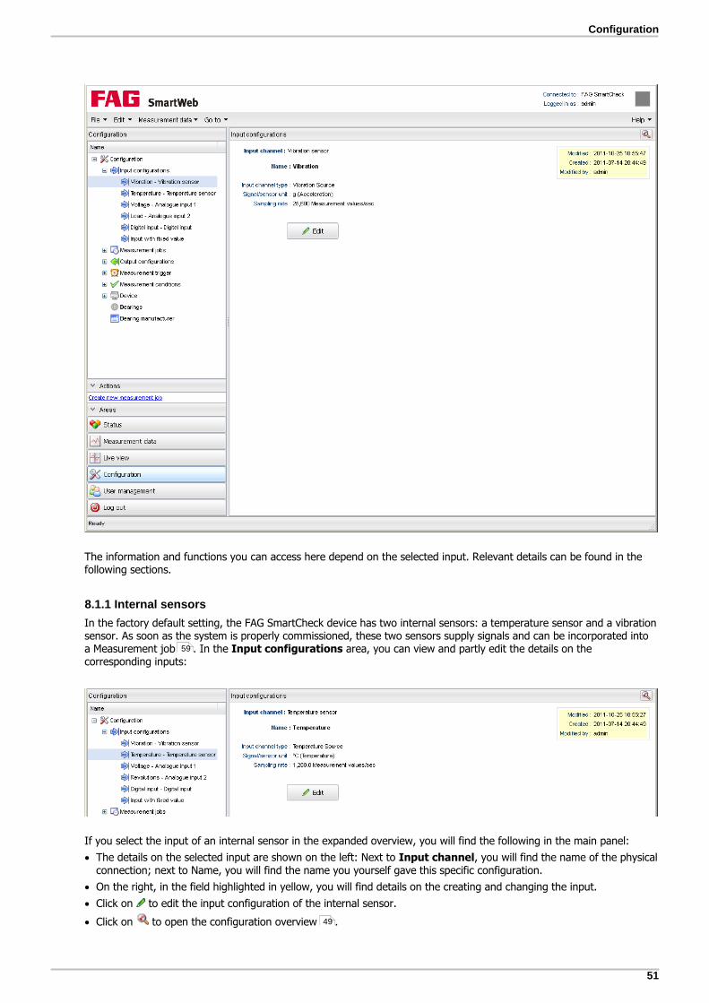
51
Configuration
The information and functions you can access here depend on the selected input. Relevant details can be found in thefollowing sections.
8.1.1 Internal sensors
In the factory default setting, the FAG SmartCheck device has two internal sensors: a temperature sensor and a vibrationsensor. As soon as the system is properly commissioned, these two sensors supply signals and can be incorporated intoa Measurement job . In the Input configurations area, you can view and partly edit the details on thecorresponding inputs:
If you select the input of an internal sensor in the expanded overview, you will find the following in the main panel:
The details on the selected input are shown on the left: Next to Input channel, you will find the name of the physicalconnection; next to Name, you will find the name you yourself gave this specific configuration.
On the right, in the field highlighted in yellow, you will find details on the creating and changing the input.
Click on to edit the input configuration of the internal sensor.
Click on to open the configuration overview .
59
49

52
How to edit the input configuration of an internal sensor
1. Click on to open the Edit input configuration window:
You can make the following changes here:
Name The input is listed under this name in the Input configurations area. Therefore, you shouldchoose a practical name which will enable you to distinguish between several inputs.
Unit Here you can change the unit of measurement for the sensor signal. By default, the unit of thecorresponding input configuration is selected here.
2. Click on OK to save your changes.
8.1.2 Analogue inputs
The SmartCheck device has two analogue inputs, which are configured as follows in the factory default setting:
Analogue 1 Unit group: voltage
Signal/sensor unit: V
Input range: 0-10 V
Analogue 2 Unit group: load
Signal/sensor unit: %
Input range: 0-20 mA
Scaling factor: 5
In the Input configurations area, you can view and partly edit the details on the corresponding inputs:
If you select an analogue input in the expanded overview, you will find the following in the main panel:
The details on the selected input are shown on the left: next to Input channel, you will find the name of the physicalconnection; next to Name, you will find the name you yourself gave this specific configuration.
Beside the details, you will find a diagram illustrating the details. If you edit the input configuration, the diagram isautomatically adjusted.
On the right, in the field highlighted in yellow, you will find details on the creating and changing the input.
Click on to edit the input configuration of the analogue input .53

53
Configuration
Click on to add additional scaling factors to the input; you can also access scaling factors e.g. when creatingmeasurement jobs .
Click on to open the configuration overview .
How to edit an analogue input configuration
1. In the expanded overview on the left, select the analogue input you would like to edit.
2. In the main panel, click on Edit to open the Edit input configuration window:
You have the following options:
Name Here, specify the name that the input is to appear under in the SmartWeb software.
Unit group Here, specify which physical value is measured by the sensor you are connecting tothis input, e.g. Frequency/speed.
Signal/sensor unit Here, select the appropriate unit of measurement for your sensor.
Input type Here, select the range of the voltage/current that applies for this input configuration.The SmartCheck device supports the following ranges for the analogue inputs:
0–10 V
0-24 V
4-20 mA
0-20 mA
Max, Scaling, Min Use these settings to determine the range within which the measurement valuesshould lie. First enter a minimum value Min. Then enter a maximum value Max ordefine the factor with which the incoming signal should be scaled in the Scalingfield. Both the diagram and the values of the respective other field are then adjustedautomatically.
3. Click on OK to save your changes.
You can also enter negative values for the Min and Max for an analogue speed input. Thisenables you to distinguish between different directions of rotation.
54
62
49

54
How to add a scaling factor to the input
You can add scaling factors to the analogue input, which you can access e.g. when creating a measurement job .Using scaling factors, you can calculate logical values for other areas from the physical value measured at one area ofthe component.
Example: With the analogue input, you measure the speed in front of the gear. The speed behind the gear is 5times smaller. You can create a scaling factor for this:1. Speed in front of the gear2. Speed behind the gear with a factor of 0.2 (1/5)
1. Click on to open the Add scaling factor window:
You have the following options:
Name The scaling factor is listed under this name, along with the other inputs. Therefore, youshould choose a practical name that will enable you to distinguish between the inputs.
Scaling factor The physical input signal is multiplied by the value you enter here.
Unit Here you can change the unit of measurement for the sensor signal. By default, theunit of the corresponding input configuration is selected here.
2. Click on OK to save your changes. The new scaling factor appears in the diagram and in the list of scaling factors:
3. To delete or edit the scaling factor, right-click to open the context menu and select the corresponding command here:
62

55
Configuration
If you delete a scaling factor which is being used by a measurement job, the system gives you awarning message. If you delete the scaling factor, you also automatically delete the relevantmeasurement job.
8.1.3 Digital input
The SmartCheck device possesses a digital input, which in the factory default setting is configured as follows:
Unit group: frequency/speed
Signal/sensor unit: RPM
Pulse per revolution: 1
Signal threshold: 7 V
Hysteresis: 2 V
When selecting the dropping resistor, please note the impedance of the input signal of yourdigital input. Note the maximum switching current of the digital switching output of the FAGSmartCheck device (1 A/30 V) and the power of the dropping resistor.
In the Input configurations area, you can view and partly edit the details for the digital input:
If you select the digital input in the expanded overview, you will find the following in the main panel:
The details on the selected input are shown on the left: next to Input channel, you will find the name of the physicalconnection; next to Name, you will find the name you yourself gave this specific configuration.
Beside the details, you will find a diagram illustrating the details.
On the right, in the field highlighted in yellow, you will find details on the creating and changing the input.
Click on to edit the input configuration of the digital input .
Click on to add additional scaling factors to the input; you can also access scaling factors e.g. when creatingmeasurement jobs .
Click on to open the configuration overview .
56
57
62
49

56
How to edit a digital input configuration
1. Select the digital input in the expanded overview on the left.
2. In the main panel, click on Edit to open the Edit input configuration window:
You have the following options:
Name Here, specify the name that the input is to appear under in the SmartWeb software.
Unit group Here you have the choice between No unit and Frequency/speed. Select theoption No unit if you want the input to display a status such as "Machine on" or"Machine off".
Signal/sensor unit Here you will only find a list box if you have selected Frequency/speed as the Unitgroup.
Inverted Activate this option to invert the digital input signal.
Pulses per revolution This option is only available when Frequency/speed is selected as the Unit group.
Signal threshold Specify in volts the average input level, above or below which the digital inputswitches; in the diagram, the Signal threshold is drawn in blue.
The specified value is rounded up/down to the nearest .0 or .5.
Hysteresis With Hysteresis, you specify in volts the range within which the input level ispermitted to drop below or rise above the Signal threshold without the digital inputswitching; in the diagram, the Hysteresis is drawn in red.
The hysteresis should be set in every case, as otherwise the signal could generatespurious pulses at the signal threshold. The poorer the signal, the higher you shouldset the hysteresis.
The specified value is rounded up/down to the nearest .0 or .5.
Example: With a Signal threshold of 5 V and a Hysteresis of 2 V, the status of the digital

57
Configuration
input remains unchanged between 4 V and 6 V.
Diagram The diagram illustrates how the input reacts to your settings, in other words how thesystem converts real input pulses e.g. between 0 V and 12 V into digital 0 and 1; witheach change, the diagram is immediately updated. The diagram in the example isinterpreted as follows:
The input signal (orange) passes the hysteresis line (red) above the signal threshold(blue). The signal output (black) reacts to this and jumps from 0 to 1. As soon as theinput signal undercuts the hysteresis line below the signal limit, the signal output reactsagain and jumps from 1 to 0.
Example: Your sensor delivers pulses between 0 V and 12 V. In this case, set the signalthreshold to 6 V and the hysteresis e.g. to 2 V.
3. Click on OK to save your changes.
How to add a scaling factor
You can add scaling factors to the digital input, which you can access e.g. when creating a measurement job . Usingscaling factors, you can calculate logical values for other areas from the physical value measured at one area of thecomponent.
Example: With the digital input, you measure the speed in front of the gear. The speed behind the gear is 5times smaller. You can create a scaling factor for this:1. Speed in front of the gear2. Speed behind the gear with a factor of 0.2 (1/5)
1. Click on to open the Add scaling factor window:
You have the following options:
Name The scaling factor is listed under this name, along with the other inputs. Therefore, youshould choose a practical name that will enable you to distinguish between the inputs.
Scaling factor The physical input signal is multiplied by the value you enter here.
Unit Here you can change the unit of measurement for the sensor signal. By default, theunit of the corresponding input configuration is selected here.
2. Click on OK to save your changes. The new scaling factor appears in the list of scaling factors:
62

58
3. To delete or edit the scaling factor, right-click to open the context menu and select the corresponding command here:
If you delete a scaling factor which is being used by a measurement job, the system gives you awarning message. If you delete the scaling factor, you also automatically delete the relevantmeasurement job.
8.1.4 Input with fixed value
In the SmartWeb software, you can create inputs with a fixed value, which you can access when creating measurementjobs. An input with a fixed value can be useful, for example, if the machine to be monitored runs at a constant speed. Inthis case, you do not have to connect a sensor; rather you can specify the speed via the fixed value. In the factorydefault setting, the SmartCheck device has one input with a fixed value, which is configured as follows:
Name: constant speed
Value: 3000
Unit: RPM
In the Input configurations area, you can view and edit the details for the fixed values:
You have the following options:

59
Configuration
Click on Edit to edit the selected input with a fixed value.
Click on Delete to delete the selected input with a fixed value.
Click on Add to add another input with a fixed value.
Click on to open the configuration overview .
How to add a new input with a fixed value
1. Click on to open the window Add fixed value:
You have the following options:
Name The input with a fixed value is listed under this name, along with the other inputs. Therefore,you should choose a practical name that will enable you to distinguish between the inputs.
Value Here you specify the fixed value.
Unit group Here you specify which unit group the fixed value belongs to, e.g. Torque, Pressure, Speedor Force.
Unit Here you can specify the unit of measurement for the fixed value. The selection optionscorrespond to the selected unit group.
2. Click on OK to save your changes. The new input with a fixed value appears in the table:
3. To Delete or Edit the input with a fixed value, select the entry in the table and then choose the correspondingcommand.
8.2 Measurement jobs
To enable the FAG SmartCheck vibration monitoring system to monitor your machine and trigger alarms if appropriate,the incoming signals (vibration, temperature etc.) must be measured and characteristic values calculated. Thecorresponding instructions are located in what are known as measurement jobs, which you can create using theSmartWeb software.
The SmartCheck device is distinguished by the support the system gives you in the creation of these measurement jobsand especially in the calculation rules for characteristic values: You create measurement jobs exclusively with the aid ofthe Configuration wizard . In the very first step of the wizard, you select a template that is suitable for yourmachine. According to the template you selected, e.g. the Gear template for the monitoring of two gears, the
49
62 64

60
SmartCheck device then automatically generates the appropriate characteristic values. In addition, a superordinate alarmcharacteristic value is generated for each measurement job, which summarises the alarm status of all characteristicvalues.
You cannot edit the characteristic values the SmartCheck device generates; you can only view them in the correspondingoverview in the SmartWeb software. However, you specify a series of framework conditions for the measurement job inthe configuration wizard, e.g. triggers or conditions , the dependency of an alarm on additional signals, or theactivation of the learning mode.
Selection of the right template and correct entries in the configuration wizard is a key factor in enabling your system toperform the monitoring as required. Consequently, the following sections are to support you in these work steps. You willfind here:
The detailed description of the Measurement jobs area.
An overview of the Steps in the configuration wizard that you follow to create a measurement job. This sectioncontains a summary of each step and any additional information further to the info texts in the configuration wizard.
An Overview of the templates available to you when creating a measurement job.
Detailed explanations of the Learning mode and Alarm maps , two special functionalities that the SmartCheckdevice provides you for monitoring. Both are activated from the configuration wizard.
8.2.1 Measurement jobs section
In the Measurement jobs area, you will find an overview of all measurement jobs you have created for theSmartCheck device. Each measurement job includes the following components:
Measurement configurations: These determine the inputs at which measurements are made and how thesemeasurements are performed.
Characteristic value configurations: These values are calculated automatically from measurement signalsaccording to internal templates.
Optional component: Triggers or conditions can be added to the measurement job in order to control theexecution of measurements.
You can view and partly edit all of these components and their details in the Measurement jobs area. In the factorydefault setting of the SmartCheck device, the basic measurement job is created:
65
60
62
64
70 72
65

61
Configuration
In the expanded overview on the left, you will find all measurement conditions for the SmartCheck device. Click on ameasurement job to access the following information and functions in the main panel:
Under Measurement job, you will see the name of the measurement job as well as any details such as triggers orconditions used. Here you will also find a yellow box with change details and the Edit, Delete and Create buttons.
Under Characteristic value configuration you will see the individual characteristic values that belong to theselected measurement job. If you click on one of the values, the details about it are displayed on the right. Thesedetails partly correspond to your own settings, which you made when creating the measurement job ; the rest areadded automatically by the wizard from system templates.
Under Measurement configuration you will see the measurements that belong to this measurement job. If youclick on one of the values, the details about it are displayed on the right. These details partly correspond to your ownsettings, which you made when creating the measurement job ; the rest are added automatically by the wizardfrom system templates.Under Characteristic value configuration, the characteristic values that belong to the selected measurement arealso automatically highlighted in bold.
You can edit the selected measurement job .
You can add new measurement jobs .
You can delete the selected measurement job. To do so, click Delete and confirm with OK.
In the top right corner, click on to open the Configuration overview .
You can find the menu item Create new measurement job in most work areas of theSmartWeb software on the left under Actions, which means that you are always able toaccess this main system task.
If a characteristic value of a measurement job is used for the alarm status configuration of anexternal device , you cannot edit or delete this measurement job.
62
62
62
62
49
90

62
8.2.2 Creating/editing new measurement jobs
The configuration wizard opens when you want to create or edit a measurement job. This guides you step by stepthrough the creation process. Here you only need to specify a few details, as the complex calculations of thecharacteristic values of a component are executed inside the system using the relevant templates .
To be able to use input signals for the monitoring, you must create the corresponding inputconfiguration before you start the wizard.
The configuration wizard consists of several steps, which are displayed in the left margin right from the start. How manysteps you need to go through depends on which component template you choose and whether you activate the Expertsettings:
The wizard queries additional information in the individual steps. Generally, the entries you needto or can make are already explained in the wizard. Simply move the mouse over the question
mark to read the explanation.
In the following sections, you will find a summary of each individual step along with additional information that goesbeyond the basic Help.
Select component
Here you choose the component you want to monitor from the predefined list. The system template that is used tocreate the measurement configuration depends on your selection here.
Specify details about the component
Here you make detailed specifications about the selected component. Make these specifications depending on the
64
50
64

63
Configuration
component, e.g. the maximum speed, the type of installation, or the number of blades or vanes. This is also where youdetermine the input signals on which the monitoring is to be based.
If the component is a bearing, you can select the bearing type straight from the system bearing database in this step. Ifit is not in the database, you can create it using the wizard.
In this step, all templates - except the Basic configuration and the Default configuration -request a Speed signal and the Maximum speed. For the speed signal, a characteristic valueis automatically created. The alarm limits for this value depend on the specified Maximumspeed. While the other characteristic values created by the wizard are listed in the last step inan overview, this characteristic value remains in the background. Consequently, you can neitherchange its alarm limit nor activate the Learning mode for it.
The system default alarm limit, which uses this characteristic value, is calculated as follows:
Pre-alarm: 1% above the specified maximum speed
Main alarm: 5% above the specified maximum speed
Apply expert settings/Apply expert settings for the Wellhausen counter
These steps only become visible if you activate the Expert settings option on the bottom left of the wizard.Furthermore, the step Apply expert settings for the Wellhausen counter is only available for the defaultconfiguration. In both steps, you have the option of adjusting some preset values of the template for your specificmeasurement job, e.g. specifying the number of spectral lines or the high-pass for the demodulation.
You should only edit this step if you possess expert knowledge.
The value that you specify for Number of spectral lines affects the length of the recordedsignals. All vibration measurements are based on this value. As such, the duration of the variousmeasurements may vary. The duration of the longest vibration measurement determines themeasurement duration for all other additional measurements:
Measuring time for vibration time signals [s] = number of lines / low-pass
Additional channels record the number of values required for the longest vibration measurementup to a maximum of 100,000 values. For an analogue input, for example, this corresponds to ameasuring period of approx. 78 s.
Apply learning mode settings
This step is only visible if you activate the Expert settings option on the bottom left of the wizard. Here you can specifythe algorithm used by the learning mode to calculate the alarm limits and the factors used to determine the main alarmand pre-alarm.
If you select the Learning mode type, you should note the following:
Standard deviation: This process takes into account when signals vary or are not verystable, i.e. when the value for sigma, the signal variance, is high.Maximum values: This selection is preset and is the better method in most cases. You canselect this method when the vibration values are very stable, i.e. when the value for sigma,the signal variance, is low.
You should only edit this step if you possess expert knowledge.
Save settings/triggers and conditions
Here you specify how often trends and time signals should be saved. In addition, you can determine whether themeasurements should depend on Measurement triggers , Time triggers, Measurement conditions or Timeconditions.
If you have not yet created any measurement triggers or measurement conditions or the existing ones do not meet yourrequirements, you can create them using the wizard. You can only create time triggers and time conditions within thewizard. You can find information on this in the Triggers and conditions section.
Additional signals
Here you can add additional input signals to the measurement configuration. This adds further trends to thecharacteristic value trends, which are generated automatically by the template.
70
82 85
65

64
The automatically created characteristic values of the additional signals can be retrieved in thecharacteristic value overview in the last step of the configuration wizard. There you can alsochange the alarm limits of these characteristic values.
Typically, it is not necessary to activate the Learning mode for the additional signals; if youdo want to authorise it, you can do so in the last step of the wizard.
Resetting/setting alarms
In this step, you specify:
Whether alarms are to be reset automatically or manually, i.e. via the Context menu , for example.
Whether and for which characteristic values the learning mode should always be authorised.
Whether the learning mode calculates alarm limits contingent on measured machine parameters (alarm map ).
Where the limits for the main alarm and pre-alarm lie: You can specify this for all characteristic values together or foreach individual characteristic value.
How the alarms are reset: You can specify this for all characteristic values together or for each individual characteristicvalue.
If you activate the option Change alarm limits in line with other signals, you also mustauthorise the learning mode; otherwise, the option has no effect.
You should not use the learning mode when the measurement range is known, e.g. fortemperature, pressure or load.
For characteristic values based on ISO, the limits of machine class II are preset for the alarmlimits. Learning mode is activated by default and can therefore overwrite the alarm limits basedon ISO, if applicable:
Here you have the following options:
Click on Select ISO class. A context menu is displayed, from which you can select therequired alarm limits.
You can manually set alarm limits that deviate from the ISO recommendations.
8.2.3 Available templates for measurement configurations
In the first step of the configuration wizard, you need to choose a template that will be used to create the measurementjob for monitoring your machine. The following list gives a rough overview of which template is most suitable for whichmachine/monitoring scenario:
Basic configuration: Use the template for broad-band measurement. It can be used for all machines, but onlyoffers a very general monitoring.
Default configuration: Use this template for broad-band measurement with several filters. It can be used for allmachines, but only offers a very general monitoring.
Gear: Use this template for the monitoring of two gears.
Journal bearing: Use this template for the monitoring of a bearing with oil film.
70
34
72

65
Configuration
Coupling: Use this template for the monitoring of a jaw coupling.
Fan: Use this template for the monitoring of fan blades.
User-defined frequency bands: Use this template to define user-defined frequency bands, where a separatecharacteristic value is created for each one. You should only use this template if you possess expert knowledge.
Managed frequency bands: Use this template to define managed frequency bands, where a separatecharacteristic value is created for each one. You should only use this template if you are an expert.
Pump: Use this template for the monitoring of pump vanes.
Belt drive: Use this template for the monitoring of a belt level.
Shaft: Use this template for the monitoring of a shaft.
Roller bearing: Use this template for the monitoring of a roller bearing.
Condition guard: Use this special template for the constant monitoring of a machine pursuant to the standard ISO10816-1.
8.2.4 Triggers and conditions
The SmartCheck device generally works through the measurement jobs in a fixed order. You can use triggers andconditions to interrupt this order. In the Memory settings/measurement triggers and conditions step, you cancreate or edit triggers and conditions:
You can create the following triggers and conditions here:
Time trigger
Measurement trigger
Time condition
Measurement condition
Relevant details can be found in the following sections.
66
67
68
69

66
You can also create and edit measurement triggers and measurement conditions without thewizard in the Measurement trigger and Measurement conditions areas. You canthen select the triggers and conditions created there from a list in the wizard.
You cannot use measurement triggers and measurement conditions for output configurations.
The diagram below provides an overview of the interaction and prioritisation of conditions and triggers:
Measurements instigated by triggers are not performed:
If the conditions are not met at the trigger point.
If a measurement instigated by a trigger is already running.
8.2.4.1 Time trigger
A time trigger allows you to specify that the measurement will take place regularly at an interval defined by you, e.g.every 5 minutes. You can only create one time trigger for each measurement job.
How to create a time trigger
1. Click the Time trigger button.
2. Enter the desired specifications under Time trigger:
82 85
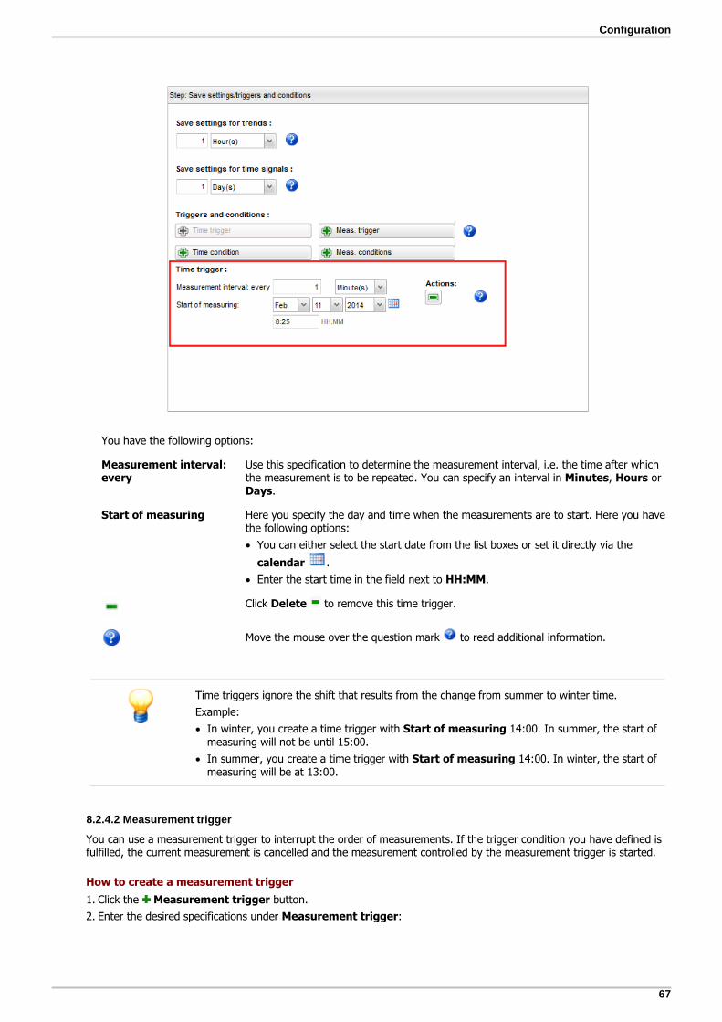
67
Configuration
You have the following options:
Measurement interval:every
Use this specification to determine the measurement interval, i.e. the time after whichthe measurement is to be repeated. You can specify an interval in Minutes, Hours orDays.
Start of measuring Here you specify the day and time when the measurements are to start. Here you havethe following options:
You can either select the start date from the list boxes or set it directly via the
calendar .
Enter the start time in the field next to HH:MM.
Click Delete to remove this time trigger.
Move the mouse over the question mark to read additional information.
Time triggers ignore the shift that results from the change from summer to winter time.
Example:
In winter, you create a time trigger with Start of measuring 14:00. In summer, the start ofmeasuring will not be until 15:00.
In summer, you create a time trigger with Start of measuring 14:00. In winter, the start ofmeasuring will be at 13:00.
8.2.4.2 Measurement trigger
You can use a measurement trigger to interrupt the order of measurements. If the trigger condition you have defined isfulfilled, the current measurement is cancelled and the measurement controlled by the measurement trigger is started.
How to create a measurement trigger
1. Click the Measurement trigger button.
2. Enter the desired specifications under Measurement trigger:

68
You have the followingoptions:
Measurement trigger(list box)
This list contains the measurement triggers that you have previously created in the Measurement trigger area. Select the required measurement trigger from here.
If you cannot find a suitable measurement trigger in the list box, click to create anew measurement trigger. The Add measurement trigger dialogue opens and youcan enter the desired specifications here. You can find details on this in the Adding/editing measurement trigger section.
Click Delete to remove this measurement trigger.
Move the mouse over the question mark to read additional information.
8.2.4.3 Time condition
You can use a time condition to ensure that measurements are only performed at a certain time.
How to create a time condition
1. Click the Time condition button.
2. Enter the desired specifications under Time condition:
82
83

69
Configuration
You have the following options:
Mon.-Sun. Activate here the days on which measurements are to start.
From ... To ... Enter here the times between which the measurements are to take place.
The time range that you specify here can also run from one day into the next.
Example: You have activated Mon and Tues and enter the following as the time range:From: 17:00 To: 8:00The time range for measurements then begins on Monday at 17:00 and ends Tuesday morningat 8:00. After a break, measurements will resume at Tuesday 17:00 and continue untilWednesday at 8:00.
Click Delete to remove this time condition.
Move the mouse over the question mark to read additional information.
If multiple time conditions are defined for a single measurement job, only one condition needsto be met for the measurement to be performed.
Time conditions ignore the shift that results from the change from summer to winter time.Example:
o In winter, you create a time condition for the period from 14:00 to 16:00. In summer,
the time period shifts to 15:00 to 17:00.
o In summer, you create a time condition for the period from 14:00 to 16:00. In winter,
the time period shifts to 13:00 to 15:00.
8.2.4.4 Measurement condition
In a similar way to the time condition, the condition you define here must be met in order for a pending measurement totake place. If a measurement is pending but the measurement condition you defined is not met, the device skips thismeasurement and goes straight to the next one.
How to create a measurement condition
1. Click the Measurement condition button.
2. Enter the desired specifications under Measurement condition:
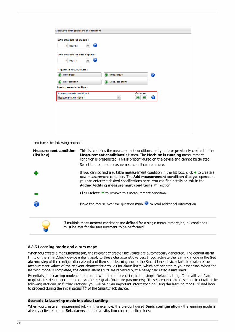
70
You have the following options:
Measurement condition(list box)
This list contains the measurement conditions that you have previously created in the Measurement conditions area. The Machine is running measurementcondition is preselected. This is preconfigured on the device and cannot be deleted.
Select the required measurement condition from here.
If you cannot find a suitable measurement condition in the list box, click to create anew measurement condition. The Add measurement condition dialogue opens andyou can enter the desired specifications here. You can find details on this in the Adding/editing measurement conditions section.
Click Delete to remove this measurement condition.
Move the mouse over the question mark to read additional information.
If multiple measurement conditions are defined for a single measurement job, all conditionsmust be met for the measurement to be performed.
8.2.5 Learning mode and alarm maps
When you create a measurement job, the relevant characteristic values are automatically generated. The default alarmlimits of the SmartCheck device initially apply to these characteristic values. If you activate the learning mode in the Setalarms step of the configuration wizard and then start learning mode, the SmartCheck device starts to evaluate themeasurement values of the relevant characteristic values for alarm limits, which are adapted to your machine. When thelearning mode is completed, the default alarm limits are replaced by the newly calculated alarm limits.
Essentially, the learning mode can be run in two different scenarios, in the simple Default setting or with an Alarmmap , i.e. dependent on one or two other signals (machine parameters). These scenarios are described in detail in thefollowing sections. In further sections, you will be given important information on using the learning mode and howto proceed during the initial setup of the SmartCheck device.
Scenario 1: Learning mode in default setting
When you create a measurement job - in this example, the pre-configured Basic configuration - the learning mode isalready activated in the Set alarms step for all vibration characteristic values:
85
87
70
72
74
75

71
Configuration
When you complete the wizard with OK, you can then start learning mode for all characteristic values for which thelearning mode was activated. You have the following options:
Press the TEACH key on the SmartCheck device to start learning mode for all characteristic values for which thelearning mode was activated.
In the SmartWeb software, open the context menu for a characteristic value. Use the Start learning modecommand to start learning mode for the selected characteristic value.
In the SmartWeb software, open the context menu for a measurement job. Use the Start learning mode for allcommand to start learning mode for all characteristic values for the selected measurement job.
The learning process then looks like this:
The FAG SmartCheck device records 1000 measurement values; here each measurement performed is saved in thetrend - independently of the memory cycle of the trend that you specified in the Save settings/triggers andconditions step. The speed of this process can depend on your triggers and conditions .
The default of 1000 measurement values can be changed in the configuration wizard. To doso, activate the Expert settings option. The Apply learning mode settings step appears,in which you can change the number of values.
Learning mode is deactivated by default for characteristic values ISO108161-1 (2 Hz to 1kHz) - velocity and ISO108161-1 (10 Hz to 1 kHz) - velocity.
As soon as the <var styleclass="Normal">SmartCheck</var> device has saved 1000 measurement values in thetrend, a new alarm limit for the relevant characteristic value is calculated on this basis; here the SmartCheck deviceuses the Maximum values as an algorithm. In the Learning mode settings step of the wizard, you canchange/adapt this procedure.
When the learning mode for a characteristic value is completed, a corresponding message appears in the logbook ,which also contains the newly calculated alarm limits. You can view the alarm limits in the trend in the Measurementdata area as well.
Once learning is complete, learning mode for this characteristic value is automatically deactivated in the measurementjob. If you wish to restart learning mode at a later point, you must tick the appropriate box again in order to activate.You can do this in either the configuration wizard or the Edit alarm settings dialogue.
65
63
36
38
62 42

72
During this process, the learning mode only determines main and pre-alarm limits. The value you specified for Signalalways larger than in the Set alarms step is automatically adjusted if the new alarm limits overlap.
Scenario 2: Learning mode and alarm map
Alarm maps are used in connection with the learning mode if your machine is operated in different operating states eachhaving its own alarm limits. In this case, you can run the learning mode dependent on one or two further signals(machine parameters). To do this, the SmartCheck device must be able to measure the corresponding signals via theanalogue or digital input. The following example shows which specifications you must make additionally in theconfiguration wizard:
Your machine, which is operated at different speeds, has a speed range of between 2000 rpm and 3000 rpm. In order tocalculate alarm limits contingent on this speed range with the learning mode, make the following entries in the Setalarms step of the configuration wizard:
Activate the Change alarm limits in line with other signals option.
For the input, select the speed input — in this example the digital input.
For Min [RPM], specify the value 2000.
For Max [RPM], specify the value 3000.
Activate the learning mode for the corresponding characteristic values.
As soon as you complete the wizard with OK, you can start learning mode in the same way as with the Default setting; learning process deviations from the default setting are as follows:
The reference speed range of 2000 to 3000 is broken down into an alarm map with 10 fixed alarm fields:
70

73
Configuration
For each of these alarm fields, the SmartCheck device takes in 1000 measurement values in order to calculate from theman alarm limit of its own for the corresponding alarm field.
For as long as an alarm field does not yet have a new alarm limit, the default alarm limit applies for the field.
Each alarm field is processed individually, which means it is possible for the learning mode to be completed in onealarm field already, while the default alarm limits still apply in the other alarm fields.
When the learning mode for an alarm field is completed, a corresponding message appears in the logbook , whichalso contains the newly calculated alarm limits.
While the learning mode is running, the status LED of the SmartCheck device flashes. When running through thealarm fields in an alarm map, the LED may stop flashing briefly because the device has reached a field that is alreadycompleted. However, it will start flashing again as soon as it reaches a field for which the learning mode is notcompleted.
You can also use the learning mode contingent on two machine parameters. In this case, you must specify a secondsignal in the Set alarms step of the configuration wizard:
42
36

74
As soon as you complete the wizard with OK, you can start the learning mode process as described above. However, thealarm map is significantly expanded, as a matrix with 100 alarm fields is now generated, with an alarm limit calculatedfor each field.
The SmartCheck device creates the characteristic value for the machine parameter(s) in thebackground; you cannot change their alarm limits manually: they depend on your entry forthe value range.
If a measured value lies outside the value range you have specified, the SmartCheck deviceuses the alarm limit of the nearest alarm field.
After a firmware update, the checkbox for Use learning mode is activated for all alarmmaps – regardless of whether or not the learning mode has already been completed for thismap. Learning mode is not activated after the update, the control maps therefore initiallyremain unchanged. As soon as you activate learning mode, all control maps are learned again.In this process, they lose all previously learned values. To prevent this, proceed as follows:In the SmartWeb software, set learning mode for each individual field by selecting one ormore fields and deactivating/activating the checkbox for Use learning mode.
General information on the learning mode
In this section, you will find useful pointers on working with the learning mode.
When is it useful/possible to use the learning mode, and when not?
For the learning mode, the machine must be in good condition, i.e. not damaged in any way. For monitoring vibrationsin accordance with ISO 10816-1, an additional requirement is that the machine vibrations should lie within the rangeof the ISO characteristic value. This is true of machines "that are normally considered acceptable for long-termoperation" (ISO definition for the good condition of a machine).
The learning mode can only determine optimal values if the machine is in its normal state/operation. You should notstart the learning mode if your machine is currently idle or being started or stopped.
If you are not sure how to find out the normal operating state of your machine, ask your customer support representative .
In general, it makes sense to use the learning mode in connection with vibration signals.
You should not use the learning mode when the measurement range is known, e.g. for temperature, pressure or load.
For additional signals, which you specify in the Additional signals step (configuration wizard), the learning mode isgenerally not necessary.
119

75
Configuration
No alarm is output during the learning phase. An alarm is output only if learning mode iscomplete and the machine exhibits high vibrations. The status LED of your SmartCheck devicethen lights up permanently in yellow or red. This could be an indication of excessive vibrations.In this case, inspect the machine and the settings in the SmartWeb software. If necessary,contact a vibration expert or your customer support representative .
How do changes to the system affect the learning mode?
In changing the value range of the signal that is used for the alarm map in the Set alarms step (configurationwizard), you also change the dimension of the alarm map. Therefore, upon completion of the wizard, all alarm limitsthat the learning mode has determined up to that point are discarded. As for a newly created measurement job, thedefault alarm limits are now in all alarm fields again.
When you work with the learning mode, the SmartCheck device takes over the default alarm limits of the characteristicvalues at the start of the process. As soon as the learning mode has been completed once, the system will then onlyuse the new alarm limits. If you change the default alarm limits of the characteristic value, the changes take effectimmediately on the system. As such, you can also adjust the alarm limits during the learning phase.
If you switch off the SmartCheck device, the learning mode will only be interrupted; the measurement results to dateare not lost.
If you turn off the machine while the learning mode is active, the learning mode will be executedon an idle machine, which will result in incorrect measurement values and thus incorrectlycalculated alarm limits too. You should therefore restart the learning mode when the machine isrunning again.
When should the learning mode be restarted and what happens then?
You should always restart the learning mode when the machine parameters or the vibration behaviour have changed.This is likely in the following cases, for example:
After repairs
After structural changes to the machine
After changes of mechanical parameters.
If the learning mode was already completed, the previous alarm limits will be retained after a restart until thecalculation of the new alarm limits is finished.
If the learning mode was not yet completed and is restarted, the values already measured will be discarded and all setvalues will need to be measured again.
How is the learning mode activated/started?
Activation
FAG SmartWeb: Via the Create new measurement job or Edit measurement job wizard in the Set alarmsstep, or via the Alarm settings button under Characteristic value configuration
Start/Restart
FAG SmartWeb: Via the context menu for measurement configurations and characteristic values, e.g. in the Statusarea.
FAG SmartCheck: via the TEACH key. This starts the learning mode for all characteristic values of your system forwhich the learning mode is authorised.
Procedure for initial set-up
For the initial set-up of the FAG SmartCheck device, proceed as follows:
1. Install the SmartCheck device and set up the connections. Details on this can be found in the FAG SmartCheck userdocumentation.
2. Create the desired configuration with the SmartWeb software. You can find an initial overview of the necessary stepson the start page of the Configuration area.
3. Only start the learning mode once your machine is in a defined normal state, i.e. temperature, pressure etc. havereached normal values. Measurements outside the normal state can negatively affect the measurement result.
119
49

76
8.3 Output configurations
For FAG SmartCheck, you can configure a total of two outputs, one analogue output and one digital output. In theOutput configurations field, you will find an overview of all outputs of the SmartCheck device currently configured. Inthe factory default setting of the SmartCheck device, the analogue output is configured as Overall alarm status:
In the expanded overview on the left, you will find all output configurations of the SmartCheck device. Click on an outputconfiguration to access the following information and functions in the main panel:
The Name and the details on the selected output configuration are displayed on the left.
On the right, in the field highlighted in yellow, you will find details on the creation and changing of the outputconfiguration.
You can edit the output configuration .
You can add a new output configuration . The maximum amount possible is one digital and one analogue outputconfiguration.
You can delete the selected output configuration. To do so, click Delete and confirm with OK.
You can test the selected output configuration . To do so, click on and define the test type. The displayabove the button indicates whether a test is currently active.
In the top right corner, click on to open the Configuration overview .
If you reconfigure the outputs on the SmartCheck device, you have the following basic options:
Digital alarm limit
You can use the digital output, a pure switching output, as a two-stage alarm limit for any characteristic valueconfiguration or for the overall alarm status. It can output whether an alarm exists or not, whereby you can determinewhether it should switch as soon as the pre-alarm is triggered or only when the main alarm is reached. For this output tooccur, the output must be connected to your controller.
Analogue alarm limit
77
77
77
81
49
79
78

77
Configuration
You can use the analogue output as a three-stage alarm limit for any characteristic value configuration or for the overallalarm status. It can output whether a pre-alarm, a main alarm or no alarm exists. For this output to occur, the outputmust be connected to your controller.
Analogue characteristic value output
You can also use the analogue output to output the characteristic value for any characteristic value configuration or forthe overall alarm status. The selected characteristic value, e.g. temperature, is given to the output as a voltage signalproportional to the size of the characteristic value and passed on to your controller, where the value can be interpreted.
You cannot use triggers or measurement conditions for an output configuration
Exact information on how to connect the outputs of the SmartCheck device with yourcontroller can be found in the FAG SmartCheck user documentation.
8.3.1 Adding/editing output configurations
You can configure the following outputs on the SmartCheck device:
Analogue characteristic value output
Analogue alarm limit
Digital alarm limit
You can edit existing output configurations at any time.
How to create an analogue characteristic value output.
1. Under Output configurations, click on Add .
2. Set the required specifications in the Add output configuration window:
You have the following options:
77
77
78
79
80

78
Name Here, enter the name under which the output configuration is to appear in theoverview.
Output channel From here, select the Analogue output option.
Characteristic valueconfiguration
In this list, you can find the overall alarm status, all measurement jobs and thecorresponding individual characteristic values of your system. For the analoguecharacteristic value output, you must select an individual characteristic value.
You can only select measurement jobs and overall alarm status for one alarmlimit.
Output type Here, select the Characteristic value output option.
Current/voltage output Here, determine the range of the voltage or current that is to apply for theanalogue characteristic value output. SmartCheck supports the following ranges:
0–10 V
0-20 mA
4-20 mA
Scaling factor, Min, Max Use these settings to determine the range within which the characteristic valueshould lie. First enter a minimum value Min. Then enter a maximum value Max ordefine the factor with which the outgoing signal should be scaled in the Scalingfield. Both the diagram and the values of the respective other field are thenadjusted automatically.
If the output value exceeds the maximum value Max, then the maximum voltageis output.
3. Click on OK to save the new output configuration.
How to create an analogue alarm limit
1. In the Actions field, click on Add .
2. Set the required specifications in the Add output configuration window:

79
Configuration
You have the following options:
Name Here, enter the name under which the output configuration is to appear in theoverview.
Output channel From here, select the Analogue output option.
Characteristic valueconfiguration
In this list you will find the overall alarm status and the individual characteristicvalues of all measurement jobs of your system. You can choose whether the alarmshould be output for the entire system or for an individual characteristic value.
Output type From here, select the Alarm output option.
Current/voltage output Here, determine the range of the voltage or current that should apply for theanalogue alarm limit. SmartCheck supports the following ranges:
0-10 V
0-20 mA
4-20 mA
Alarm limit From here, you determine whether the alarm output is to output the pre-alarm,the main alarm or the pre and main alarms. Below the drop-down list, youcan find information on how current/voltage are distributed to the alarm statuses.
3. Click on OK to save the new output configuration.
How to create a digital alarm limit
1. Under Actions, click on Add .
2. Set the required specifications in the Add output configuration window:

80
You have the following options:
Name Here, enter the name under which the output configuration is to appear in theoverview.
Output channel Here, select the Digital output option.
Characteristic valueconfiguration
In this list, you can find the overall alarm status, all measurement jobs and thecorresponding individual characteristic values of your system. You can choosewhether the alarm should be output for the entire system, a measurement job oran individual characteristic value.
Output type This is where the Alarm limit option is specified.
Alarm limit From here, you determine whether the alarm output is to output the pre-alarm,the main alarm or the pre and main alarms. In the list box, you can findinformation on how the output reacts to the alarm statuses.
3. Click on OK to save the new output configuration.
How to edit an output configuration
1. Select Output configuration in the expanded overview on the left.
2. Under Output configurations, click on Edit and set the required specifications in the Edit outputconfiguration window. Here, among other things, you can also change an analogue alarm limit to a characteristicvalue output and vice-versa.
3. Click on OK to accept your changes.

81
Configuration
8.3.2 Test output configuration
You have the option of activating a test for your output configuration and thus verifying whether your outputconfiguration is working correctly. You can then determine whether the cabling and the connection to a controller ordisplay are correct. If a test is already active, it is cancelled as soon as another alarm output is tested.
In the following sections, you will find details on how to test your configured alarm output or your configuredcharacteristic value output .
How to test a configured alarm output
1. Under Output configurations, click .
2. In the Test output configuration window, enter the desired specifications:
You have the following options:
Test duration This is where you define the test duration.
Tested alarm type Here you can select what the test is to simulate:
No alarm: the test simulates a status without an alarm.
Pre-alarm: the test simulates a pre-alarm.
Main alarm: the test simulates a main alarm.
3. Click OK to confirm your settings and start the test. You will then be informed that the test is active and informed onwhat is being tested:
4. To cancel the test, click again.
81
82

82
How to test a configured characteristic value output
1. Under Output configurations, click .
2. In the Test output configuration window, enter the desired specifications:
You have the following options:
Test duration This is where you define the test duration.
Voltage Here, enter the value for voltage or current that is to be tested.
3. Click OK to confirm your settings and start the test. You will then be informed that the test is active and informed onwhat is being tested:
4. To cancel the test, click again.
8.4 Measurement trigger
The SmartCheck device generally works through the measurement jobs in a fixed order. However, you can interrupt thisorder using a measurement trigger. As soon as the trigger condition is fulfilled, the measurement controlled by themeasurement trigger is started (after completion of the current measurement).
In the Measurement trigger area, you will find an overview of all measurement triggers. In the factory default setting,no measurement trigger is configured for the SmartCheck device. As soon as you have defined your own measurementtriggers, they are available to you when creating measurement jobs .62

83
Configuration
In the expanded overview on the left, you will find all measurement triggers of the SmartCheck device. Click on ameasurement trigger to access the following information and functions in the main panel:
The Name and the details on the selected measurement trigger are displayed on the left.
The entry for Input channel is a link that takes you straight to the corresponding input configuration.
The entry for Measurement job is a link that takes you straight to the overview of the measurement job in whichthis measurement trigger is used.
On the right, in the field highlighted in yellow, you will find details on creating and changing the measurement trigger.
You can edit the measurement trigger .
You can add a new measurement trigger .
You can delete the selected measurement trigger. To do so, click Delete and confirm with OK.
In the top right corner, click on to open the Configuration overview .
When the condition for a measurement trigger is met, the measurement is startedimmediately, even if this means that an ongoing measurement is interrupted. Measurementsthat themselves have been started by a measurement trigger are not interrupted.
If a measurement trigger is used in multiple measurement jobs, these jobs are executedsequentially when the trigger condition is met.
8.4.1 Adding/editing measurement trigger
You can add as many measurement triggers and edit as many existing measurement triggers as you like to theSmartCheck device.
How to create a measurement trigger
1. Under Measurement trigger, click on Add .
85
83
49
83 85

84
2. In the Add measurement trigger window, make the desired specifications:
You have the following options:
Name Here, enter the name under which the measurement trigger is to appear in theoverview. This name will also appear in the corresponding list box if you want to usethe measurement trigger in a measurement job.
Input channel Here, select the input whose signal you want to use for the measurement trigger. Youwill find in the list box all inputs and scaling factors of your system.
Unit This value is automatically filled for the input channel you have selected.
Calculation type This is where you select the characteristic value most suitable for your signal. The Offset option is available for many application types.
Threshold Specify here the value from which the measurement trigger should take effect: If thethreshold value is exceeded or fallen below - according to the Edge - the SmartCheckdevice interrupts the current measurement and starts the measurement linked to themeasurement trigger.
Measurement values A trigger calculates its current value using the last measured number of values; enterthis number here. This value is therefore used to define the number of measurementvalues that the calculation type configured above should calculate, and the time rangeover which this value is calculated. You therefore influence the speed at which atrigger reacts to changes in the input signal and the sensitivity of the trigger's reactionto signal disruptions:
A smaller number causes a faster reaction.
A larger number makes the trigger less sensitive to disruptions.
Example: The sample rate is 1280 values/second (e.g. for an analogue input) and you setMeasurement values to 1280. If you have selected Offset as the calculation type, thecalculated value corresponds to the average over one second via the input channel.
Edge Determine here whether the threshold has to be exceeded or fallen below for themeasurement trigger to take effect:
Falling: The measurement trigger takes effect when the threshold is fallen below.
Rising: the measurement trigger takes effect when the threshold is exceeded.
Storage period Determine here whether you wish to store values regularly in order to monitor themeasurement trigger. If values are stored regularly, you can view the trend of themeasurement trigger in the Measurement data area and verify, for example, thatthe device is actually taking measurements.
You have the following options:
Never: Select this option if no values are to be stored for a trend.
n minutes/hours/days: Enter here the frequency at which values are to be stored
50

85
Configuration
for the trend in minutes, hours or days.
A status change - i.e. the execution of the trigger - is always stored, regardless of thesetting selected here.
3. Click on OK to save the new measurement trigger.
How to edit a measurement trigger
1. Select the measurement trigger in the expanded overview on the left.
2. Click on Edit and make the desired specifications in the Edit measurement trigger window.
3. Click on OK to accept your changes.
You can determine the number of Measurement values according to the following roughguidelines:
A small number of measurement values allows the trigger to switch more quickly.
A small number of measurement values reacts sensitively to short pulses.
A large number of measurement values is preferable for restless, inconstant signals.
The storage period determines how frequently the trend values of the measurement triggerare saved. However, if the trigger relates to an analogue input in 4-20 mA mode, the followingrestriction applies:
If the value at the analogue input falls below 4 mA, this channel becomes invalid. The values ofthe trigger are then no longer measured or saved until the channel is valid again (i.e. the valueat the input rises above 4 mA). This period is displayed with a grey background in the trend.
8.5 Measurement conditions
The FAG SmartCheck device generally works through the measurement jobs in a fixed order. Using a measurementcondition, you can ensure that measurements are skipped: if a measurement is pending but the measurement conditionyou defined is not met, the device skips this measurement and goes straight to the next one.
If a measurement is pending and the measurement condition is met, the measurement is performed. However, evenduring a measurement, the system continually monitors whether the measurement condition is still being met. As soonas the measurement condition is no longer being met, the measurement is cancelled.
In the Measurement conditions area, you will find an overview of all measurement conditions. In the factory defaultsetting for the SmartCheck device, the Machine is running measurement condition is preconfigured.
As soon as you have defined your own measurement conditions, they will be available to you when creatingmeasurement jobs .
86
62

86
In the expanded overview on the left, you will find all measurement conditions for the SmartCheck device. Click on ameasurement condition to access the following information and functions in the main panel:
The Name and the details on the selected measurement condition are displayed on the left.
The entry for Input channel is a link that takes you straight to the corresponding input configuration.
The entry for Measurement job is a link that takes you straight to the overview of the measurement job in whichthis measurement condition is used.
On the right, in the field highlighted in yellow, you will find details on creating and changing the measurementcondition.
You can edit the measurement condition .
You can add a new measurement condition .
You can delete the selected measurement condition. To do so, click Delete and confirm with OK.
In the top right corner, click on to open the Configuration overview .
The preconfigured Machine is running measurement condition is set in the basicmeasurement job and ensures that the measuring job is only executed when the relevantmachine is actually running. You cannot delete or rename this measurement condition.
However, you should adjust this measurement condition on your machine immediately afterinitial operation of the FAG SmartCheck device: In the factory default setting, the fulfilment ofthe Machine is running measurement condition is based on vibration signals. Edit themeasurement condition so that it meets the requirements of your machine. For example, theengine speed is usually a better criterion for determining whether the machine is running.
The Machine is running measurement condition is usually added to each newly createdconfiguration by default. However, you can also delete it manually.
88
87
49
87

87
Configuration
8.5.1 Adding/editing measurement conditions
On your SmartCheck device, you can add as many measurement conditions and edit as many existingmeasurement conditions as you like.
How to create a measurement condition
1. Under Measurement conditions, click on Add .
2. In the Add measurement condition window, make the desired specifications:
You have the following options:
Name Here, enter the name under which the measurement condition is to appear in theoverview. This name will also appear in the corresponding list box, if you want touse the measurement condition in a measurement job.
Input channel Here, select the input channel whose signal you want to use for the measurementcondition. You will find in the list box all inputs and scaling factors of yoursystem.
Unit This value is automatically filled for the input channel you have selected.
Calculation type This is where you select the characteristic value most suitable for your signal. The Offset option is available for many application types.
Measurement values A condition calculates its current value using the last measured number of values;enter this number here. This value is therefore used to define the number ofmeasurement values that the calculation type configured above should calculate,and the time range over which this value is calculated. You therefore influence thespeed at which a condition reacts to changes in the input signal and the sensitivityof the condition's reaction to signal disruptions:
A smaller number causes a faster reaction.
A larger number makes the condition less sensitive to disruptions.
Example: The sample rate is 1280 values/second (e.g. for an analogue input) and youset Measurement values to 1280. If you have selected Offset as the calculation type,the calculated value corresponds to the average over one second via the input channel.
Bottom threshold /
Upper threshold
With these two thresholds, you determine the range within which themeasurement condition counts as met; the measurement associated with thiscondition is then performed.
In our example, this range is between 40 and 60°C; with a value of e.g. 65°C, themeasurement condition would not be met and the measurement would be skippedor cancelled.
87 88
50

88
Storage period Determine here whether you wish to store values regularly in order to monitor themeasurement condition. If values are stored regularly, you can view the trend ofthe measurement condition in the Measurement data area and verify, forexample, that the device is actually taking measurements.
You have the following options:
Never: Select this option if no values are to be stored for a trend.
n minutes/hours/days: Enter the frequency at which values are to be storedfor the trend in minutes, hours or days here.
A status change - i.e. the fulfilment of the condition - is always stored, regardlessof the setting selected here.
3. Click on OK to save the new measurement condition.
How to edit a measurement condition
1. Select the measurement condition in the expanded overview on the left
2. Click on Edit and enter the desired specifications in the Edit measurement condition window.
3. Click on OK to accept your changes.
You can determine the number of Measurement values according to the following roughguidelines:
A small number of measurement values allows the measurement condition to switch morequickly.
A small number of measurement values reacts sensitively to short pulses.
A large number of measurement values is preferable for restless, inconstant signals.
The storage period determines how frequently the trend values of the measurement conditionare saved. However, if the measurement condition refers to an analogue input in 4-20 mAmode, the following restriction applies:
If the value at the analogue input falls below 4 mA, this channel becomes invalid. The values ofthe measurement condition are then no longer measured or saved until the channel is validagain (i.e. the value at the input rises above 4 mA). This period is displayed with a greybackground in the trend.
8.6 External devices
Industrial plants use controllers that contain data such as process parameters; this data is extremely useful for vibrationmonitoring purposes. The External devices area gives you the option of integrating this data into monitoring withthe <var styleclass="Normal" style="font-size:9pt;">FAG SmartCheck</var> device, and of making data from the FAGSmartCheck device accessible to the controllers. In order to avail of this potential, the following steps must be taken:
You must first add the controller that you would like to integrate as an external device . In doing so you essentiallydefine the name of the controller and how the FAG SmartCheck device can connect with the controller via yournetwork.
It is also possible to configure station forwarding in the FAG SmartWeb software for accessing the remote controller inthe internal controller network.
For problem-free communication between the controller and the FAG SmartCheck device, there must be an Ethernetconnection between the two. You must also configure the correct settings for the IP address, net mask and thegateway, if applicable.
If multiple FAG SmartCheck devices are to communicate with one controller, an individual port must be reserved in thecontroller for each device.
If you would like to read data from the controller, you must create one or more external inputs for it. For this typeof input, you can determine how often and from which controller registers the data is read, as well as the value range.You also specify the signal unit and signal value range to which the register data is to be converted.
For each controller, you can set up as many external inputs as you wish and you can use them in the SmartWebsoftware in exactly the same way as you use the inputs that are found in the Input configuration area; externalinputs are available for measurement jobs , measurement conditions and measurement triggers inparticular.
If you would like to make controller data from the SmartCheck device accessible, you must create a configuration filewith external outputs . Here, you define the update frequency and the characteristic values for which the alarm
89
91
93
50
59 85 82
94
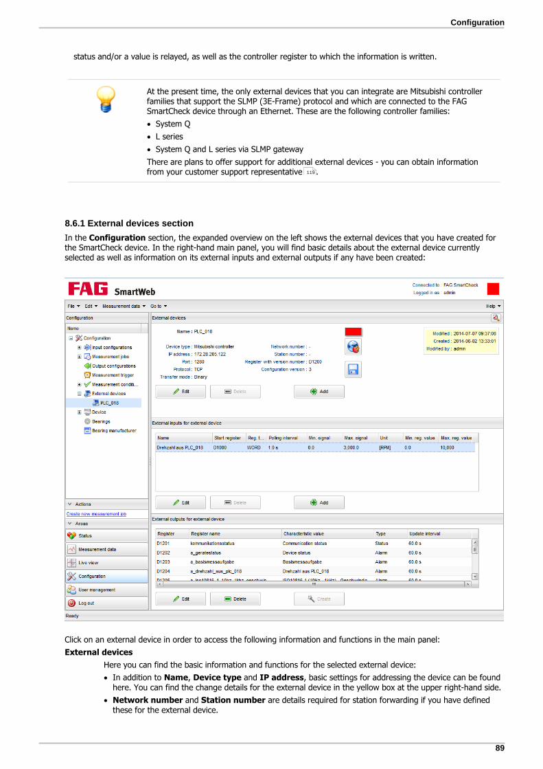
89
Configuration
status and/or a value is relayed, as well as the controller register to which the information is written.
At the present time, the only external devices that you can integrate are Mitsubishi controllerfamilies that support the SLMP (3E-Frame) protocol and which are connected to the FAGSmartCheck device through an Ethernet. These are the following controller families:
System Q
L series
System Q and L series via SLMP gateway
There are plans to offer support for additional external devices - you can obtain informationfrom your customer support representative .
8.6.1 External devices section
In the Configuration section, the expanded overview on the left shows the external devices that you have created forthe SmartCheck device. In the right-hand main panel, you will find basic details about the external device currentlyselected as well as information on its external inputs and external outputs if any have been created:
Click on an external device in order to access the following information and functions in the main panel:
External devices
Here you can find the basic information and functions for the selected external device:
In addition to Name, Device type and IP address, basic settings for addressing the device can be foundhere. You can find the change details for the external device in the yellow box at the upper right-hand side.
Network number and Station number are details required for station forwarding if you have definedthese for the external device.
119

90
Register with version number relates to the configuration file with external outputs that you havecreated for the device: here you can find the register into which the version of the configuration file(Configuration version) is written. This number functions as a safeguard against unintentionaloverwriting of the register.
: If you select an external device, this icon is updated; it indicates whether communication with theexternal device is functioning or not: a green icon indicates problem-free communication. If the icon is red,there is a communication problem. In this case you see an error message if you hover the mouse over theicon.
To update the icon again you must click on .
Click on to test the connection to the external device.
Click on to download the configuration file. When you have created external outputs , you need thisfile in order to prepare the external device for the transfer of the data.
Click on Edit to edit the external device. You can find details for this under Adding/editing anexternal device .
Click on Add to add additional external devices. You can find details for this under Adding/editing anexternal device .
You can delete the selected external device. To do so, click Delete and confirm with OK.
In the top right corner, click on to open the Configuration overview .
An external device that you have linked to a measuring job cannot be deleted. In this case,the Delete button is deactivated. To delete this external device, you must first delete themeasuring job in which it is used.
External inputs for external device
Here you can find an overview in table form of the external inputs that you have created for the selectedexternal device. If you select an external device, the following information and options will be displayed here:
The table contains information on the relevant external inputs, in addition to the Name e.g. also theregister in which the controller starts reading out the data (Start register), the signal value range intowhich the data is translated (Min. signal to Max. signal) and the register value range it covers (Min.reg. value to Max. reg. value).
Click on Edit to edit the external input. For details of this, please refer to Adding/editing an externalinput .
Click on Add to add further external inputs. For details of this, please refer to Adding/editing anexternal input .
You can delete the selected external input. To do so, click Delete and confirm with OK.
An external input that you have linked to a measuring job cannot be deleted. In this case,the Delete button is deactivated. To delete this external device, you must first delete themeasuring job in which it is used.
External outputs for an external device
You can use characteristic values that are calculated in the SmartCheck device to transfer their alarm statusand/or values to a controller. To do this, create a configuration file with external outputs and transfer thealarm status and/or value of characteristic values via this file to the controller.
If external outputs have already been created, you will find the following information in the Externaloutputs for an external device section:
The table indicates the characteristic values for which the alarm status and/or value (Type) is transferredto the external device, how often this happens (Update interval) and the register into which theinformation is written.
Click on Edit to edit the external outputs with the assistance of the wizard. For more details about this,please refer to Creating/editing external outputs .
Click on Create to create the external outputs with the assistance of the wizard. For more details aboutthis, please refer to Creating/editing external outputs .
You can delete the external outputs. To do so, click Delete and confirm with OK.
97
88
92
91
49
59
94
93
59
94
94

91
Configuration
After you have created or edited the external outputs in the SmartWeb software, you musttransfer the corresponding information to your external device. For details, please refer to thesection Integrating an external device into the system .
If you want to use the FAG SmartUtility software to download a configuration from theSmartCheck device and send this to other devices, the external outputs are not included in thetransfer. This prevents multiple FAG SmartCheck devices from writing to the same registersfor the external controller. Please import the configuration file with the external outputsmanually in this case, as described in the Integrating an external device into thesystem section.
8.6.2 Adding/editing an external device
In order to be able to receive the data from an external controller as an input signal, you will need to set up the relevantcontroller as an external device and communicate the controller network data to the SmartCheck device.
This is how you create an external device
1. Under External devices, click on Add .
2. In the Add external device window, enter the desired specifications:
You have the following options:
Name This is where you specify the name under which the external device is to appearin the SmartWeb software.
Device type The external device type is displayed here.
IP address This where you specify the IP address under which the external device in yournetwork can be accessed.
Port This where you specify the port via which connection with the external device isset up.
Station forwarding Activate this field if you would like to forward the communication to anothercontroller via the IP address specified above. In this case you must also specifythe following:
Network number: specify the network number of the remote controller here.
97
97

92
Station number: specify the station number of the remote controller here.
Example:In order to access the PLC 3 controller, specify the following:- the IP address of PLC 1- the network number and station number of PLC 3:
The data from the FAG SmartCheck device is then forwarded by PLC 1 to PLC 3 via therealtime network.
Protocol
Transfer mode
This is where you specify the Network protocol and the Transfer mode fortransferring data between the FAG SmartCheck device and the external device.
Make sure that your selection here matches the settings in the external device.
Connection test Click on this button to check the input connection data. If the test is successful,the box next to the button turns green; otherwise it appears in red.
If you hover the mouse above the red box you will also receive a messageexplaining why the connection is not working.
3. Click on OK to save the new external device.
For the connection between FAG SmartCheck and the external device to work, the IP addressesof the two devices must be in the same range. That means that - depending on the net mask -the first three numbers of the four-digit IP address must be identical. You can also access theexternal device with the FAG SmartCheck device via a gateway. If you have any questionsregarding this, contact your network administrator.
If the IP address of the external device is outside the IP range of the FAG SmartCheck device,but is accessible via a gateway, proceed as follows:
1. Open the FAG SmartUtility software.
2. Click on Configure sensor(s).
3. In the first step in the wizard, select the FAG SmartCheck device.
4. In the second step in the wizard, specify the gateway for the FAG SmartCheck device.
5. Close the Wizard with Send.
You can obtain more detailed information about creating a gateway from your systemadministrator. For details on working with the <var styleclass="Normal-Einruecken">FAGSmartUtility</var> software, please refer to the manual for the FAG SmartUtility software.
The combination of IP address and port must be unique. If you need more combinations - forstation forwarding, for example - you must enable more ports in the external device asappropriate.
This is how you edit an external device
1. Select the external device on the left side of the pop-up overview.
2. Under External devices in the main panel, click on Edit . Enter the desired information in the window Editexternal device.

93
Configuration
3. Click on OK to accept your changes.
8.6.3 Adding/editing an external input
The FAG SmartCheck device receives information on process parameters in the controller via external inputs.
This is how you create an external input
1. On the left side of the expanded overview, select the external device to which you would like to add an input.
2. Under External inputs for an external device: [device name], click on Add .
3. In the Add external input window, enter the desired specifications:
You have the following options:
Name Here, specify the name under which the external input is to appear in theSmartWeb software.
Start register Specify the register here that is to be read out. If you choose a data type under Register type for which two registers must be read out, Start register refers tothe lower of the two registers. This is where the readout starts.
Register type This is where you specify the data format to be used in the Start register or inthe register closest to the start register. This specification defines:
whether one register (16 bits) or two registers (32 bits) are read out and
how large the maximum register value range can be.
The selection options available have the following formats or register valueranges:
INT 16 bit -32,768 to 32,767
WORD 16 bit 0 to 65,535
DINT 32 bit -2,147,483,648 to 2,147,483,647
DWORD 32 bit 0 to 4,294,967,295

94
REAL 32 bit ±1.5 * 10-45 to ±3.4 * 1038
Unit group and
Unit
This is where you specify the physical value and measurement unit into which thevalue from the controller is to be converted.
Polling interval This is where you specify how often the value is to be queried from the controller.
A long polling interval is sufficient for values that only change slowly e.g. thetemperature. This can reduce the amount of data and the load on the controller.
The logbook message "Connection refused" indicates thatthe FAG SmartCheck device is attempting to connect tothe external device again despite the fact that the lastconnection is not yet complete. You can prevent this fromoccurring by increasing the polling interval.
Register value Initially, these fields are filled automatically as soon as you have selected a Register type. You then have the option of adjusting the Min. register valueand/or Max. register value manually. This may be necessary if the registervalue range is smaller than the range that was set automatically.
Signal value Use these settings to determine the range within which the measurement valuesshould lie. First enter a minimum value Min. Then enter a maximum value Max ordefine the factor with which the calculated signal should be scaled in the Scalingfield. Both the diagram and the values of the respective other field are thenadjusted automatically.
4. Click on OK to save the new external input.
Example:
The register R100 is defined as WORD in the controller. The entire numerical range from 0 to 65,535 is limitedto the range from 0 to 10,000. This range corresponds to a speed of between 0 and 3000 RPM.Your settings are then the following:
Start register R100
Register type WORD
Unit group Frequency/speed
Unit RPM
Min. register value 0
This value is set automatically.
Max. register value 10,000
The number 65,535 is set automatically and you will need to adjust it manually.
Max. signal value 3000 (RPM)
Min. signal value 0 (RPM)
This is how you edit an external input
1. On the left side of the pop-up overview, select the external device the input of which you would like to edit.
2. In the table, under External inputs for an external device: [device name], select the desired external input.
3. Click on Edit and enter the desired specifications in the Edit external input window.
4. Click on OK to accept your changes.
8.6.4 Creating/editing external outputs
CAUTION Only create a configuration file with external outputs if you are certain that the register area tobe written to is free, or that it is not being used in the controller program. Otherwise, it ispossible that the FAG SmartCheck device may overwrite important data in your controller.
You can use the external outputs to define the characteristic values whose alarm status, value, and/or alarm limit istransferred to the external device. You can also determine the registers in the external device that will be written to in

95
Configuration
this process. In addition, you require certain information from the external outputs to prepare your controller for thewriting process. You can find details in this regard in the relevant section of the chapter Integrating an externaldevice into the system .
If you have created the configuration file with external outputs successfully and have also prepared the controllerappropriately, the FAG SmartCheck device can write the following values for each characteristic value into the relevantcontroller register:
Value Abbreviation Meaning
1 no_alarm Alarm status: No alarm - marked in green in the FAG SmartWebsoftware.
2 pre_alarm Alarm status: Pre-alarm - marked in yellow in the FAGSmartWeb software.
3 main_alarm Alarm status: Main alarm - marked in red in the FAG SmartWebsoftware.
4 charval_error An error occurred when calculating the characteristic value; it ispossible for example that no rotational speed was determined,even though this is necessary for the characteristic value.
5 value Value: Number in IEEE 32-bit format
This is how you create the external outputs
1. Select the external device for which you would like to create the external outputs on the left side of the pop-upoverview.
2. Under External outputs for an external device: [device name], click on Create in order to open the wizard.It will guide you through the creation or editing in two steps.
3. In the first step, you must select registers and characteristic values:
97

96
You have the following options:
Start register This is the point where you specify the first register of the register block in whichthe alarm status is to be stored.
The version number of the configuration file is stored in this first register with theexternal outputs; the alarm statuses and/or values of the selected characteristicvalues are written into all subsequent registers.
Update interval This is where you specify how often the alarm statuses and/or values are to betransferred to the controller.
Characteristic valueselection
This is where you select the characteristic values whose alarm statuses and/orvalues are to be transferred to the controller. The characteristic values availablehere depend on the measurement jobs that you have created.
Alarm status/alarm limits Select here if you want to transfer the alarm status, value, and/or the alarm limitof the characteristic value to the controller for every characteristic value. You canonly transfer the communication status, the device status and the overriding alarmcharacteristic value ("basic configuration" here, for example) as alarm statuses.You can then only select the device status if at least one other characteristic valuetransfers an alarm status.
The alarm limits cannot be selected until the value and/oralarm status has been selected.
Measurement triggers and measurement conditions cannot be selected as a configuration for anexternal output.
4. Click on OK to move to the second step. This is where you specify the register name:
59

97
Configuration
Under Register names, you can use the relevant register as a variable in the GX Works2 software.
As far as possible, the register names in the table are generated automatically from the characteristic value names.The sequence of the entries can be edited by selecting one or more entries and moving them up or down with the
arrow keys. You can update the register with update . The characteristic values are sorted alphabetically bymeasuring task name and characteristic value name. You can edit any name by double-clicking on the relevant line.The following naming conventions apply:
The name must be input in ASCII format.
A-Z, a-z, 0-9 and _ are allowed characters
The first character must be a letter.
The number of characters must be between 1 and 32 at most.
5. Click on OK to close the wizard and confirm the configuration with external outputs.
6. To guarantee problem-free communication, you must also transfer the configuration file with external outputs to yourexternal device. In the controller's programming environment, the registers into which the FAG SmartCheck device willwrite the alarm status, values, and/or alarm limits is marked as 'reserved'. For details, please refer to the section Integrating an external device into the system .
The Register with version number contains the current version number of theconfiguration file with external outputs. This information functions as a safeguard againstunintentional overwriting of registers: when the configuration file has changed in such a wayas to affect the configuration of the controller, the version number for the controller inquestion is immediately incremented. This means that the version number in the controller nolonger agrees with the version number on the FAG SmartCheck device. Alarm statuses and/orvalues can no longer be written into the controller, and you will receive an error message.
Only when you have transferred the new configuration file to the controller (refer to thesection Integrating an external device into the system ) are the alarm statuses and/orvalues again written into the controller.
The characteristic value Communication status writes values into the controller that provideinformation about communication problems between the FAG SmartCheck device and thecontroller.
Value Abbreviation and meaning
0 communication_ok: No problems
1 error_configuration_inconsistent: The characteristic value structure onthe FAG SmartCheck device has changed, the data can no longer be written tothe control system at this time. In order to do this again, the configuration filefrom the FAG SmartCheck device must be downloaded again and read into thecontroller .
2 error_reading_values: The FAG SmartCheck device cannot read one ormore values from the control system, or the values are incorrect. For moreinformation, refer to the Logbook .
3 error_alarm_state_not_updated: The FAG SmartCheck device cannotwrite one or more values to the control system. For more information, refer tothe Logbook .
This is how you edit the external outputs
1. On the left side of the pop-up overview, select the external device whose external outputs you would like to edit.
2. Under External outputs for an external device: [device name], click on Edit to open the wizard.
3. Make the desired changes with the assistance of the wizard and confirm them by clicking on OK.
4. To guarantee problem-free communication, you must also transfer the changed configuration file to your externaldevice. For details, please refer to the section Integrating an external device into the system .
98
98
98
36
36
98

98
8.6.5 Integrating an external device into the system
In the following sections you will find a detailed example of how to integrate specific controllers as external devices intothe <var styleclass="Normal">FAG SmartCheck</var> system, and the steps required in order to initiate communicationbetween your control system and the FAG SmartCheck device. The following example is currently available:
Mitsubishi - GX Works2 software
In this section, you will find detailed information regarding how to prepare your controller for communication with theFAG SmartCheck device and the settings in the FAG SmartWeb software that are required for this. Here is an overview ofthe necessary steps:
1.Set up communication settings in the controller
2.Create external device in the FAG SmartWeb software
3.Create external inputs in the FAG SmartWeb software
4.Create external outputs in the FAG SmartWeb software
5.Save configuration file with external outputs in the FAG SmartWeb software
6.Import configuration file into GX Works2
7.Compile program and transfer it to the controller
These steps are aligned with the sample specifications you will find in the Initial situation section.
Initial situation
The following communications parameters apply to your Mitsubishi controller:
IP address of the controller 172.28.205.122
Port (Host Station Port No.) Decimal: 1280 or hexadecimal: 0500
Network protocol TCP (MC protocol)
Transfer mode (CommunicationData Code)
Binary
Station forwarding None
You would like to use the connection between the controller and the FAG SmartCheck device as follows:
You would like to read the rotational speed information from register D1000 of the controller. This register has theWORD register type, and a possible value range 0-10,000, which should in turn be transformed to the 0-3000 RPMsignal range.
In addition, the FAG SmartCheck device must write the alarm status of the basic configuration and the alarm statusand value of the ISO characteristic value into the Mitsubishi controller registers. This writing process must begin inregister D1200.
8.6.5.1 Mitsubishi GX Works2 software
Step 1: create communication settings in the controller
First set all the parameters required for communication with the FAG SmartCheck device:
1. Start the GX Works2 software.
2. Click on Project > Open.
3. Open the project that contains the program for your controller.
4. In the navigation window, double-click on Parameter > PLC Parameter.
98
98

99
Configuration
5. In the Built-in Ethernet Port Setting tab, click on Open Setting.
6. Enter the following settings:
Protocol TCP
Open System MC Protocol
Host Station Port No. decimal: 1280 (corresponds to hexadecimal: 0500)
7. Click on End to accept the settings.

100
8. Under Communication Data Code, set the Binary Code transfer mode.
9. Activate Enable online change (FTP, MC Protocol) so that the FAG SmartCheck data can be written into thecontroller.
10.Click on End.
11.Integrate the program into the Task.

101
Configuration
12.Compile the program by selecting Compile > Rebuild All in the menu.
13.Transfer the program to the controller.
Continue configuring the external device in the FAG SmartWeb software.
Step 2: create the external device in the FAG SmartWeb software
Under External devices, click on Add and enter the following setting in the Add external device window:

102
Name PLC_018
IP address 172.28.205.122
Port decimal: 1280 (corresponds to hexadecimal: 0500)
Protocol TCP
Transfer mode Binary
You can find additional information regarding how to create an external device in the section Adding/editing anexternal device .
You can click on the Connection test button to verify your entries: if the area next to it turnsgreen your information is correct.
Step 3: create external inputs in the FAG SmartWeb software
Under External inputs for an external device: PLC_018, click on Add and enter the following settings in the Addexternal input window:
91

103
Configuration
Name Speed from PLC_018
Start register D1000
Register type WORD
Unit group Frequency/speed
Unit RPM
Register value Change the value for Max to 10,000.
Signal value For Min, enter the value 0 and for Max, enter the value 3000.
For further information regarding how to create an external input, please refer to the section Adding/editing anexternal input .
If you have created inputs in the FAG SmartWeb software, you can use the live view tocheck whether data is being received by the FAG SmartCheck device.
This input can be used exactly like an internal input for measuring jobs
Step 4: create external outputs in the FAG SmartWeb software
Under External outputs for an external device: PLC_018, click on Create and enter the following settings in thefirst step of the wizard:
93
46

104
Start register D1200
Available characteristicvalues
Select the alarm status for the basic measurement job characteristic value and thealarm status and value for the ISO 10816-1 characteristic value. To do this, click onthe box next to the characteristic value.
In the second step of the wizard, you can, if necessary, adjust the Register names that have been assignedautomatically. You can find more information, such as how you can create a configuration with external outputs, in the Creating/editing external outputs section.
Step 5: save configuration file with external outputs in the FAG SmartWeb software
1. In the External devices field, click on to open the configuration file with external outputs:
94

105
Configuration
2. Select the contents of the window with CTRL+A, copy them to the clipboard with CTRL+C and insert them into aneditor (e.g. Microsoft Editor) with CTRL+V.
3. Save the file with any name and the extension .ASC (example: FAG_SmartCheck01.asc).
If you use the Mozilla Firefox browser, you can save the file directly as an ASCII file with the Save as function.
Please make sure that the file has the extension .ASC so that it can be read by the GX Works2software.
Step 6: read the configuration file into GX Works2
Please create a backup copy of the existing project before importing the FAG SmartCheckconfiguration file.
1. Click on Project > Open Other Data > Read ASC Format File.
2. Select the ASCII file (.ASC) you have just created and click on OK.
3. The FAG SmartCheck configuration file is read in and inserted into the tree as a new Global Label with thedesignation Global_Vars.

106
The characteristic values along with the associated registers are displayed if you click in the Device column on DetailSetting:
Step 7: compile the program and transfer it to the controller
1. Compile the program by selecting Compile > Rebuild All in the menu.
2. Save the program and transfer it to the controller.
8.7 Device
Under Device, you will find the Device settings and System time settings . Click on the desired area to viewthe main settings of the SmartCheck device. Some settings can also be changed here.
8.7.1 Device settings
Under Device Settings, details on the FAG SmartCheck device, the network, and the keys and the status LED on thedevice are listed:
106 109

107
Configuration
You can find the following information here:
Device settings
The device name, serial number and MAC address (network address) of the SmartCheck device arelisted here.
You can only change the device name; to do so, click on Edit and then enter a new device name.
Key/LED settings
FAG SmartCheck has 2 keys and one status LED. Under Key/LED settings, you can specify the actionspermissible with these keys. In this way, you protect the SmartCheck device against inadvertent operation.You can also specify here whether the status LED should indicated alarm statuses. As a rule, the followingsettings are possible:
Reset alarm(s) This switches off all existing alarms.
Restart learning mode This restarts the Learning mode ; current measurement values andalarm limits are retained; only the process for determining new alarm limitsis restarted.
Reboot device This restarts the SmartCheck device, i.e. the device is shut down andbooted up again.
Restore factory defaultsetting
This resets the SmartCheck device to the factory default setting. All thesettings and configurations you made are lost.
Enable status LED This option is activated by default.
If you want to deactivate this option, switch off the alarm signals of thestatus LED. The SmartCheck device then no longer indicates the alarmstatus through a red, yellow or green light.
It still flashes yellow and red for instance when the firmware is updating.
34

108
The key lock is activated by default as of SmartCheck firmware version 1.4.26 to protect against inadvertentoperation. You can find details on which key or key combination you have to press in each case in the FAGSmartCheck user documentation.
To change the key/LED settings, proceed as follows:
1.Click on Edit
2. In the Edit key/LED settings window, define the permissible actions:
If you deactivate a key option, the corresponding key can no longer be used for this purpose. In ourexample, this applies to Restore factory default setting.
If you deactivate the Enable status LED option, the alarm status is no longer indicated on theSmartCheck device.
3.Click on OK to save your changes.
Network settings
The current settings for DHCP, Host name, IP address, Gateway and Netmask are listed here. Tochange the network settings, proceed as follows:
1.Click on Edit
2. In the Edit network settings window, enter the desired specifications:
You have the following options:
No DHCP With this option, you can specify the IP address or continue to use theSmartCheck device's default IP address.
If No DHCP is activated, you must also specify the other settings in thisstep, e.g. IP Address, Netmask or Gateway.
DHCP client mode
(load host name from server)
With this option, the SmartCheck device automatically receives an IPaddress within your network. The host name is specified via the network'sDNS server (reverse DNS).
DHCP client mode With this option, the SmartCheck device automatically receives an IP

109
Configuration
(send host name to server) address within your network. The host name is registered by theSmartCheck device in the network's DNS server.
3.Click on OK to save your changes.
If you change the IP address of the SmartCheckGeräts, you no longer have access tothe SmartWeb software under the previous address. You must then enter the newaddress in the browser in order to load the software again.
If the IP address is allocated automatically via DHCP, the SmartCheck device canonly be accessed via the automatically allocated IP address. You can no longer usethe default IP address.
8.7.2 System time settings
FAG SmartCheck has an internal clock, which will be operational provided that the device issupplied with power. However, as it has no buffer battery, it becomes inoperative as soon asthe power supply is interrupted – unless you have connected an external battery or powersupply to the battery input.If you restore the interrupted power supply and you have selected Set system timemanually, you should correct the system time, otherwise the internal clock will continue torun from the time of the last successful measurement before the power failure.For information on how to connect the internal clock to an external battery, refer to the userdocumentation FAG SmartCheck.
If a new SmartCheck device does not have access to information on the current time, the timeinformation is taken from the firmware.
Under System time settings, various details on the system time of SmartCheck are listed:
The following information and functions can be found here:
System time
Here the current date and current time of the SmartCheck device are displayed.
NTP activated
Here you can see whether the SmartCheck device loads the system time from an NTP server, i.e. a timeserver in the network. If so, Yes will be displayed here.
NTP server
If the SmartCheck device loads the system time from an NTP server, you will see the name of the server here.
Edit button
To change the settings for system time and NTP server, proceed as follows:
1. Click on Edit

110
2. In the Edit system time window make the desired specifications:
Method Here you can specify what the system time of the SmartCheck device should be basedon. The time setting can have the time of the connected PC or that of an NTP serveras its reference. You can also enter it manually.
If the system time is based on an NTP server, synchronization runs constantly. For thismethod, therefore, the SmartCheck device must have a permanent connection to thenetwork, and the NTP server must always be accessible.
Date Only in the case of Set system time manually: enter the current date and thecurrent time here. You can either select the date from the list boxes or set it directly
from the calendar .
NTP server Only for Use NTP server to synchronise system time: specify the name of theNTP server here. using the IP address of the desired NTP server.
3. Click on OK to save your changes.
8.8 Bearing
FAG SmartCheck contains a comprehensive bearing database, to which you can add further bearings. These bearings areavailable when you create a new measurement configuration . In the Bearings area, you will find an overview withsearch function:
62

111
Configuration
Here you will find the following information and functions to access:
Searching for bearings by manufacturer is possible. You can expand the corresponding list box as much as you likein the Bearing manufacturer area.
You can search for bearings by name in the database. To do so, enter the name in the Search criteria field. Hereyou have the following options:
The placeholder * stands for any character string.
The placeholder ? stands for any single character.
Upper/Lower case is irrelevant.
The details on the bearing currently selected are displayed under Bearing information. In the example, you can seethe details for the first bearing in the list. In the yellow box on the right, you will find the details on the creation andchanging of the selected bearing.
You can add a new bearing
You can copy and edit existing bearings
You can delete copies of bearings or newly created bearings. To do this, select the relevant bearing, click on Delete, and choose OK to confirm.
Bearings that are used in a measurement job cannot be deleted.
In the top right corner, click on to open the Configuration overview .
You can neither delete nor edit the bearings from the preset database. However, you can copy abearing from the database and then edit the copy.
8.8.1 Adding/editing bearings
You can expand the FAG SmartCheck bearing database as much as you like. In doing so, you have two options:
You can add new bearings .
113
112
113
49
112

112
You can copy existing bearings , edit the copy and then save it under a new name.
How to add a new bearing
1. Under Bearing information, click on Add .
2. In the Add bearing window, make the desired specifications:
You have the following options:
Name Enter the name of the bearing here. You can also find the bearing under thisname if you want to select it for a measurement job.
Manufacturer Select the manufacturer for the new bearing here. What is in this list box isdetermined by your selections in the Bearing manufacturer area.
Normalised kinematicfrequencies
These specifications are important for the correct calculation of bearing damagefrequencies and thus for the reliable monitoring of this component. You can findthe corresponding information on BPFI, BPFO, BSF and FTF in the technicaldata of the bearing.
Alternatively, you can have the normalised kinematic frequencies calculated withthe help of the program, using the geometry of the bearing (see below).
Calculate normalisedkinematic frequencies
Click here to calculate normalised kinematic frequencies with the aid of thebearing geometry. In this case, you need the load angle, the diameter of thepitch circle and of the roller element, and the number of roller elements:
113
113

113
Configuration
If you want to add a double-row bearing, only enter the number of one row in Number of roller elements.
Make the corresponding specifications and then click on Calculate. The softwarecalculates the values for the normalised kinematic frequencies from the geometryand transfers them to the corresponding fields.
Verify bearing Click here to check your specifications for plausibility. This check reduces theprobability of you having made incorrect specifications for the normalisedkinematic frequencies. Otherwise, the bearing is accepted into the databasewithout a plausibility check.
3. Click on OK to add the new bearing to the database.
How to copy and edit a bearing
The bearing database, which is already available in the factory default setting of the FAG SmartCheck device, is write-protected; the individual bearings can be neither edited nor deleted. However, you can copy a bearing from the databaseand edit the copy, e.g. to create a new bearing with only minor deviations. To do this, proceed as follows:
1. Select the bearing you want to copy and edit
2. Under Bearing information, click on Copy
3. In the Copy bearing window, make the desired specifications. If you do not change the name here, FAG SmartCheckcreates by default a bearing with the name Copy of [name of the original bearing].
4. Click on OK to save your changes and transfer the bearing into the database.
Calculating normalised kinematic frequencies from the bearing geometry requires expertknowledge. Only with the correct specifications for angles and diameters can the values for thebearing be determined correctly and lead to a correct measurement configuration.
8.9 Bearing manufacturer
If you add a new bearing in the Bearing area, you also have to specify the manufacturer of the bearing. Youmanage the manufacturers available for selection in the Bearing manufacturer area:
110

114
Here you have the following options:
Add manufacturer: Under Manage manufacturers, click on Add , enter the name of the manufacturer andconfirm with OK.
Edit manufacturer: Under Manage manufacturers, click on Edit , change the name of the manufacturer andconfirm with OK.
Delete manufacturer: Under Manage manufacturers, click on Delete and confirm with OK.
In the top right corner, click on to open the Configuration overview .
You can neither delete nor edit manufacturers that you have already used in the specificationsfor a bearing.
49

115
User management
9 User management
Click on the User management button to open the corresponding area. Here you can change, add and delete usergroups and users in the SmartWeb software. You can also activate and deactivate the user management here. On theleft, you will find an overview of all user groups and users. The user currently logged in is displayed in the top right inthe title bar next to Logged in as.
In the factory default setting, the user groups Administrator, Remote and Guest are created with the users admin,remote and guest. If you select a group or an individual user, you will see the corresponding details and rights in themain panel:
Here you have the following options:
User groups
If, as in the example, you select a user group in the expanded overview, you will find the following in themain panel:
The name of the selected User group is displayed on the left.
Below the name, you will find the list of Rights for the selected user group. The rights activated here—i.e. the ones that are ticked—are granted to every user you create for this user group. To change therights, click on Edit .
Beside the rights, you will find the list of Members of the user group. This gives you a quick overview ofthe users who, for example, were affected by a change to the user group.
You can add or edit a user group . This excludes the system user groups Administrator and Remote,which cannot be changed.
You can delete a user group provided that it is empty, i.e. it no longer contains any users. To do so, click Delete and confirm with OK.
On the right, in the field highlighted in yellow, you will find details on creating and changing the user group.
The symbol indicates user groups that you can neither change nor delete. This includes the system usergroups Administrator and Remote.
116
117

116
User
If you select a user in the expanded overview, you will find the following in the main panel:
The User ID and the details on the selected user are displayed on the left.
Beside the details, you will find the list of the Rights for the selected user. The rights activated here -i.e. the ones that are ticked - are granted to the user via membership of a user group. The rights can onlybe changed for the whole user group.
You can add or edit a user . This excludes the system users admin and remote, which cannot bechanged.
You can delete a user. To do so, click Delete and confirm with OK.
On the right, in the field highlighted in yellow, you will find details on creating and changing the user. The
symbol indicates users whom you can neither change nor delete. This includes the system users adminand remote.
Rights
When you create a user group, you can grant rights that will then apply for every user in this user group. Thefollowing rights are available:
Edit system settingsThis allows the settings found under Device settings and System time settings to be edited bythe user.
Create configurations, Edit configurations and Delete configurationsWith these rights, the user can create, edit and/or delete configurations accordingly. Excluded from thisright are the input and output configurations, which have their own rights (see below).
Configure inputs and Configure outputsWith these rights, the user can configure inputs and outputs and create scaling factors.
Create users/user groups, Edit users/user groups and Delete users/user groupsIf you grant these rights, the user can execute the corresponding functions of the user management.
Download dataThis right is necessary if the user wants to download and analyse data via the SmartUtility interface fromthe SmartCheck device.
Reset alarm(s)This right allows the user, using the SmartWeb software, to switch off the alarms of the SmartCheck device.
View trend/real-time data etc.This allows the user to open the Live view and Measurement data areas and use thecorresponding functions there.
Delete measurement dataThis right allows the user to delete measurement data that is on the SmartCheck device.
Activate/Deactivate user management
By default, you can open the SmartWeb software without logging in with your user name and password. Sothat the software and the SmartCheck device can only be operated by authorised users, you can Activateuser management. With activated user management, each user has to log in with user name andpassword. Users only have the rights granted to their user group.
To activate user management, click on the corresponding menu item, enter a new administrator passwordtwice and then click on OK. You must then refresh the FAG SmartWeb software in your browser, so that theuser management is active.
To deactivate user management again, click on the corresponding menu item, enter the administratorpassword and then click on OK. The administrator password is reset to the factory default setting. Noweveryone can log in without user name and password and everyone has administrator rights.
Change password
This function is only available if user management is activated.
Click on Change password, enter your new password twice and then click on OK. Now you can use the newpassword.
116
118
106 109
46 38
45

117
User management
If you are using the SmartUtility software, you can store your user name and password in thesoftware settings. To do so, your details here must match the user name and password storedin the user management of the SmartWeb software.
In the factory default setting, system users have the following passwords:
User ID admin: Password admin123
User ID remote: Password remote123
User ID guest: Password guest123
9.1 Adding/editing user group
To be able to create a user, you first need a user group. A user group consists of a name and a selection of rights .These rights pass automatically to every user in this group. Thus, the rights users have when using FAG SmartCheck aredefined by means of the group they belong to.
How to add a user group
1. In the overview on the left, select User groups.
2. In the main panel, click on Add .
3. In the window Add user group, make the desired specifications:
You have the following options:
User group Here, enter the name under which the user group is to appear in the overview.
Right Here, activate the rights that are to apply for users in this user group. You caneither select each right individually or activate them all at the same time via Right.
4. Click on OK to save the new user group.
How to edit a user group
1. In the expanded overview, click on the desired user group.
2. Click on Edit and enter the desired specifications in the Edit user group window.
3. Click on OK to adopt your changes.
116

118
9.2 Adding/editing users
You can only add users in connection with a user group. The user group is used to define the rights that the user hasfor FAG SmartCheck.
How to add a user
1. In the overview on the left, select User.
2. In the main panel, click on Add .
3. In the Add user window, make the desired specifications:
You have the following options:
User ID Here enter the user ID with which the user will log into SmartCheck in future.
Password Enter here the password that the user will use to log into SmartCheck in future.
User group Specify here the user group that the user is to belong to. Use the user group todetermine the rights that the user will have.
Surname, first name
email, phone
Specify here the contact data of the user. This information is optional.
Comment Enter here any comment you may want to add about this user.
4. Click on OK to save the new user.
How to edit a user
1. In the expanded overview, click on the user.
2. Click on Edit and enter the desired specifications in the Edit user window.
3. Click on OK to adopt your changes.
116

119
Manufacturer/support
10 Manufacturer/support
Manufacturer
FAG Industrial Services GmbH
Kaiserstraße 100
52134 Herzogenrath
Germany
Tel.: +49 (0) 2407 9149-66
Fax: +49 (0) 2407 9149-59
Support: +49 (0) 2407 9149-99
Website: www.schaeffler.com/services
Further information: www.FAG-SmartCheck.com
Contact: [email protected]
Please send all correspondence directly to FAG Industrial Services GmbH!
A subsidiary of
Schaeffler Technologies AG & Co. KG
PO Box 1260
97419 Schweinfurt
Germany
Georg-Schäfer-Straße 30
97421 Schweinfurt
Germany
Support
Tel.: +49 (0) 2407 9149 99
Email: [email protected]
We provide support services for the FAG SmartCheck device and related software products. A detailed description of thetype and scope of the support services we provide can be found online at www.FAG-SmartCheck.com.