Embed Size (px)
Citation preview
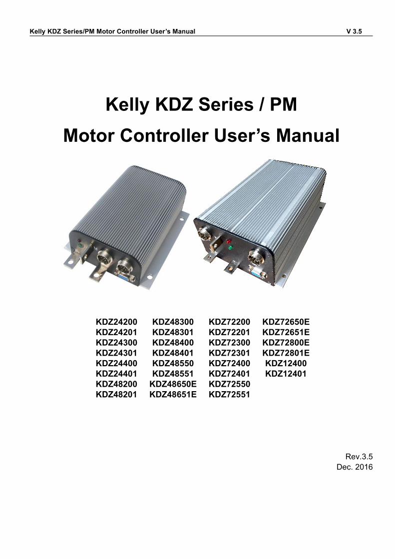
Kelly KDZ Series/PM Motor Controller User’s Manual V 3.5
Kelly KDZ Series / PMMotor Controller User’s Manual
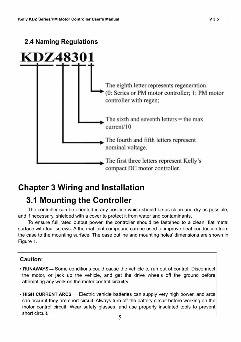
KDZ24200 KDZ48300 KDZ72200 KDZ72650EKDZ24201 KDZ48301 KDZ72201 KDZ72651EKDZ24300 KDZ48400 KDZ72300 KDZ72800EKDZ24301 KDZ48401 KDZ72301 KDZ72801EKDZ24400 KDZ48550 KDZ72400 KDZ12400KDZ24401 KDZ48551 KDZ72401 KDZ12401KDZ48200 KDZ48650E KDZ72550KDZ48201 KDZ48651E KDZ72551
Rev.3.5Dec. 2016
Kelly KDZ Series/PM Motor Controller User’s Manual V 3.5
1
Contents
Chapter 1 Introduction.................................................................................................2
1.1 Overview............................................................................................................. 2
Chapter 2 Main Features and Specifications..........................................................3
2.1 General functions...............................................................................................3
2.2 Features.............................................................................................................. 4
2.3 Specifications..................................................................................................... 4
2.4 Naming Regulations..........................................................................................5
Chapter 3 Wiring and Installation.................................................................................5
3.1 Mounting the Controller....................................................................................5
3.2 Connections........................................................................................................8
3.2.1 Front Panel of KDZ Series or PM Motor Controller:......................... 8
3.2.2 Standard Wiring of KDZ Series or PM Motor Controller................ 11
3.2.3 Communication Port.............................................................................15
3.3 Installation Checklist.......................................................................................15
Chapter 4 Maintenance.............................................................................................16
4.1 Cleaning............................................................................................................16
4.2 Configuration....................................................................................................16
Table 1: LED CODES...................................................................................................17
Contact Us:.....................................................................................................................18
Kelly KDZ Series/PM Motor Controller User’s Manual V 3.5
2
Chapter 1 Introduction1.1 OverviewThis manual introduces the Kelly KDZ Series/PM Motor controllers’ features, their installation
and their maintenance. Read the manual carefully and thoroughly before using the controller. Ifyou have any questions, please contact the support center of Kelly Controls.
Kelly’s programmable motor controllers provide efficient, smooth and quiet controls forelectric vehicles like golf carts, go-carts, electric motorcycles, forklifts and hybrid vehicles, as wellas electric boats and industrial motor speed control. It uses high power MOSFET’s and, fast PWMto achieve efficiencies of up to 99% in most cases. A powerful microprocessor brings incomprehensive and precise control to the controllers. It also allows users to adjust parameters,conduct tests, and obtain diagnostic information quickly and easily.
Kelly KDZ Series/PM Motor Controller User’s Manual V 3.5
3
Chapter 2 Main Features and Specifications2.1General functions
(1) Extended fault detection and protection. The LED flashing pattern indicates the fault sources.(2) Monitoring battery voltage. It will stop driving if the battery voltage is too high and it will
progressively cut back motor drive power as battery voltage drops until it cuts out altogether atthe preset “Low Battery Voltage” setting.
(3) Built-in current loop and over current protection.(4) Configurable motor temperature protection range.(5) Current cutback at low temperature and high temperature to protect battery and controller. The
current begins to ramp down at 90℃(controller case temperature), shutting down at 100℃.(6) The controller keeps monitoring battery recharging voltage during regenerative braking,
progressively cutting back current as battery voltage rises then cutting off regen altogetherwhen voltage goes too high.
(7) Maximum reverse speed is configurable to half of the maximum forward speed.(8) Configurable and programmable with a host computer though RS232 or USB. Provide free
GUI which can run on Windows XP/2000, Windows 7 and Vista(recommend using KellyStandard USB To RS232 Converter).
(9) Provision of a +5 volt output to supply various kinds of sensors, including Hall effect type.(10) Multifunctional and configurable 3 switch inputs: brake switch, reversing switch, throttle or
forward switch. Active low.(11) 3 analog 0-5V inputs that default to throttle input, brake input and motor temperature input.(12) Pulsed reverse alarm output.(13) Maximum reverse power is configurable to half power.(14) Configurable motor over-temperature detection and protection with the recommended
thermistor KTY84-130/150 or KTY83-122.(15) Optional 12V output power which can only be applied for Switch signals or LED. Any heavy
load is inhibited.
Caution! Regeneration has braking effect but does not replace the function of a mechanical brake.A mechanical brake is required to stop your vehicle. Regen IS NOT a safety feature! Controllermay stop regen, without warning, to protect itself or the battery(it won’t protect you!).
Kelly KDZ Series/PM Motor Controller User’s Manual V 3.5
4
2.2 Features•Intelligence with powerful microprocessor.•Synchronous rectification, ultra low drop, and fast PWM to achieve very high efficiency.•Voltage monitoring on voltage source 12V and 5V.•Hardware over current protection.•Hardware over voltage protection.•Current limit and torque control.•Low EMC.•LED fault code.•Battery protection: current cutback, warning and shutdown at configurable high and lowbattery voltage.• Rugged aluminum housing for maximum heat dissipation and harsh environment.•Rugged high current terminals, and rugged aviation connectors for small signal.•Thermal protection: current cut back, warning and shutdown at high temperature.•Configurable Current-Mode or Voltage-Mode when Field Switch is enabled, to achieve highersafety and reliability.•Configurable high pedal protection: the controller will not work if high throttle is detected at poweron.•Brake switch is used to start regen.•0-5V or 0-5K brake signal is used to command regen current.•Capable of detecting short-circuit fault in the main contactor at power on.•Easy installation: 1-4V "Hall Active" throttle, or 0-5K or 0-5V potentiometer(<100K) can work.•Standard PC/Laptop computer is used to do programming. No special tools needed.•User program provided. Easy to use. No cost to customers.
2.3 Specifications•Frequency of Operation: 16.6kHz.•Standby Battery Current: < 0.5mA.•Controller power supply current, PWR, <150mA.•Configurable battery voltage range, B+. Max operating range: 8V to 136V•Standard Throttle Input: 0-5K(2-wire resistive pot), 0-5V (3-wire resistive pot), 1-4V (hall activethrottle).•Analog Brake and Throttle Input: 0-5V or 0-5K.•Reverse Alarm, Main Contactor Coil Driver, Meter.•Full Power Temperature Range: 0℃ to 50℃ (controller case temperature).•Operating Temperature Range: -30℃ to 90℃, 100℃ shutdown (controller case temperature).•Motor Current Limit, 1 minutes: 200A-800A, depending on the model.•Motor Current Limit, continuous:80A-320A, depending on the model.
Kelly KDZ Series/PM Motor Controller User’s Manual V 3.5
5
2.4 Naming Regulations
Chapter 3 Wiring and Installation3.1 Mounting the ControllerThe controller can be oriented in any position which should be as clean and dry as possible,
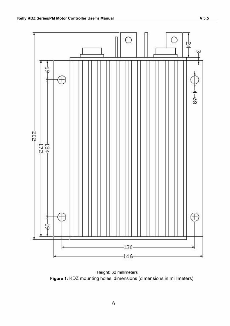
and if necessary, shielded with a cover to protect it from water and contaminants.To ensure full rated output power, the controller should be fastened to a clean, flat metal
surface with four screws. A thermal joint compound can be used to improve heat conduction fromthe case to the mounting surface. The case outline and mounting holes’ dimensions are shown inFigure 1.
Caution:• RUNAWAYS— Some conditions could cause the vehicle to run out of control. Disconnectthe motor, or jack up the vehicle, and get the drive wheels off the ground beforeattempting any work on the motor control circuitry.
• HIGH CURRENT ARCS — Electric vehicle batteries can supply very high power, and arcscan occur if they are short circuit. Always turn off the battery circuit before working on themotor control circuit. Wear safety glasses, and use properly insulated tools to preventshort circuit.
Kelly KDZ Series/PM Motor Controller User’s Manual V 3.5
6
Height: 62 millimetersFigure 1: KDZ mounting holes’ dimensions (dimensions in millimeters)
Kelly KDZ Series/PM Motor Controller User’s Manual V 3.5
7
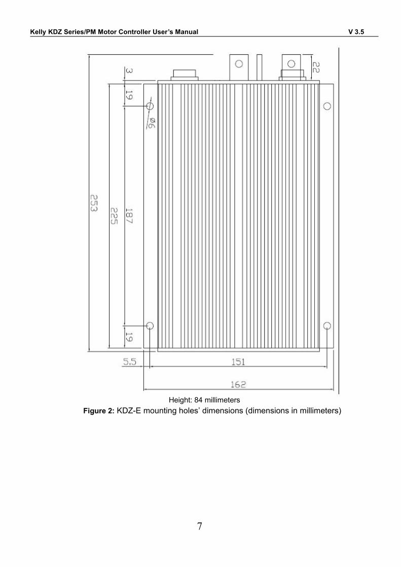
Height: 84 millimetersFigure 2: KDZ-E mounting holes’ dimensions (dimensions in millimeters)
Kelly KDZ Series/PM Motor Controller User’s Manual V 3.5
8
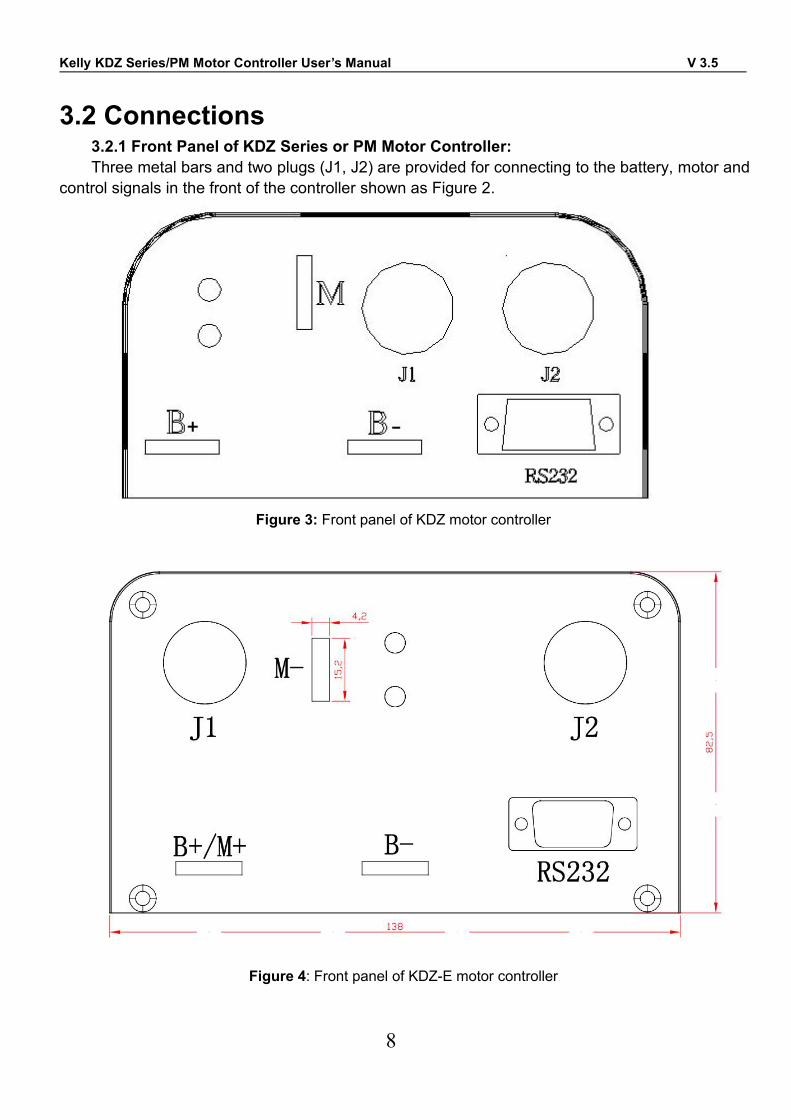
3.2 Connections3.2.1 Front Panel of KDZ Series or PM Motor Controller:Three metal bars and two plugs (J1, J2) are provided for connecting to the battery, motor and
control signals in the front of the controller shown as Figure 2.
Figure 3: Front panel of KDZ motor controller
Figure 4: Front panel of KDZ-E motor controller
Kelly KDZ Series/PM Motor Controller User’s Manual V 3.5
9
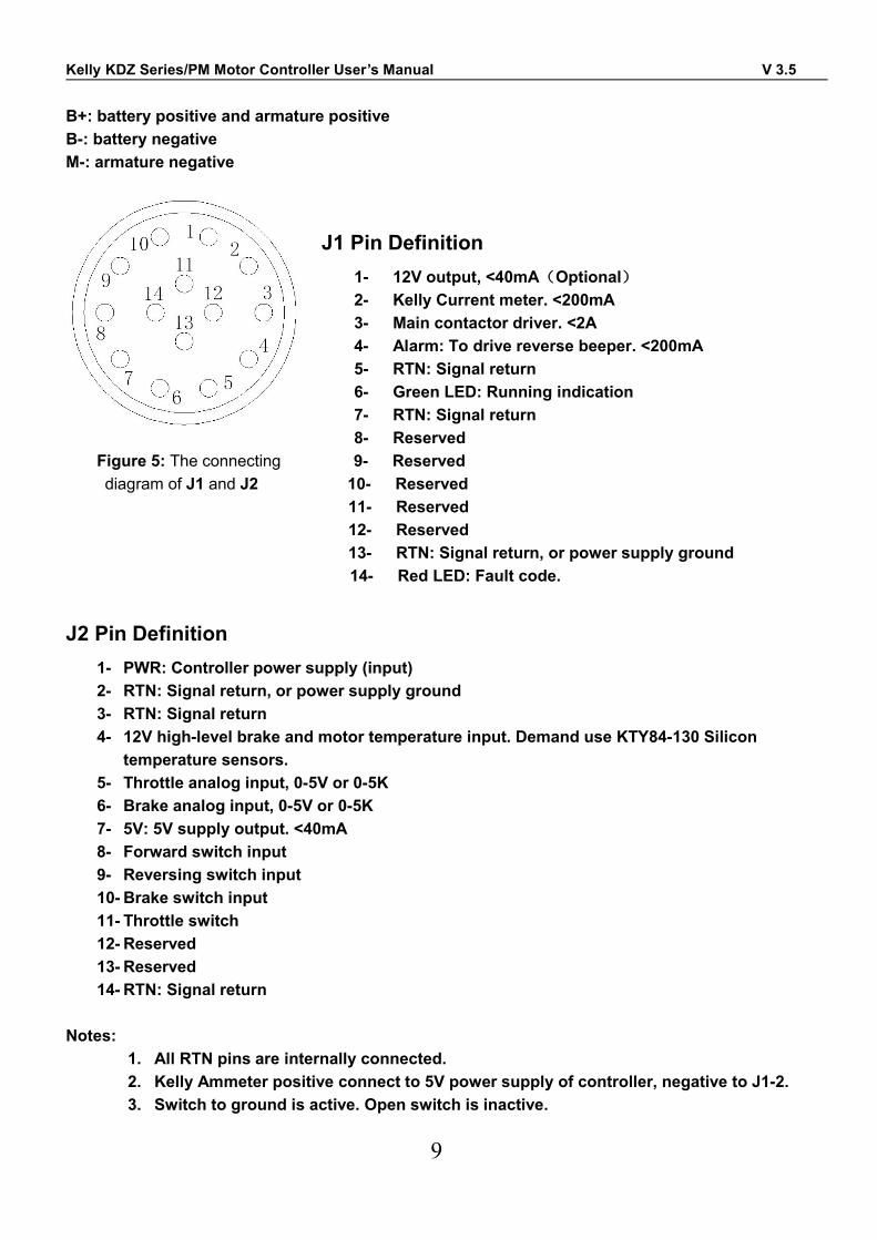
B+: battery positive and armature positiveB-: battery negativeM-: armature negative
J1 Pin Definition1- 12V output, <40mA(Optional)2- Kelly Current meter. <200mA3- Main contactor driver. <2A4- Alarm: To drive reverse beeper. <200mA5- RTN: Signal return6- Green LED: Running indication7- RTN: Signal return8- Reserved
Figure 5: The connecting 9- Reserveddiagram of J1 and J2 10- Reserved
11- Reserved12- Reserved13- RTN: Signal return, or power supply ground14- Red LED: Fault code.
J2 Pin Definition1- PWR: Controller power supply (input)2- RTN: Signal return, or power supply ground3- RTN: Signal return4- 12V high-level brake and motor temperature input. Demand use KTY84-130 Silicon
temperature sensors.5- Throttle analog input, 0-5V or 0-5K6- Brake analog input, 0-5V or 0-5K7- 5V: 5V supply output. <40mA8- Forward switch input9- Reversing switch input10- Brake switch input11- Throttle switch12- Reserved13- Reserved14- RTN: Signal return
Notes:1. All RTN pins are internally connected.2. Kelly Ammeter positive connect to 5V power supply of controller, negative to J1-2.3. Switch to ground is active. Open switch is inactive.

Kelly KDZ Series/PM Motor Controller User’s Manual V 3.5
10
Caution:• Do not apply power until you are certain the controller wiring is correct and has beendouble checked. Wiring faults will damage the controller.• Ensure that the B- wiring is securely and properly connected before applying power.• The preferred connection of the system contactor or circuit breaker is in series with the B+line.• All contactors or circuit breakers in the B+ line must have precharge resistors across theircontacts. Lack of even one of these precharge resistors may severely damage the controllerat switch-on.
Kelly KDZ Series/PM Motor Controller User’s Manual V 3.5
11
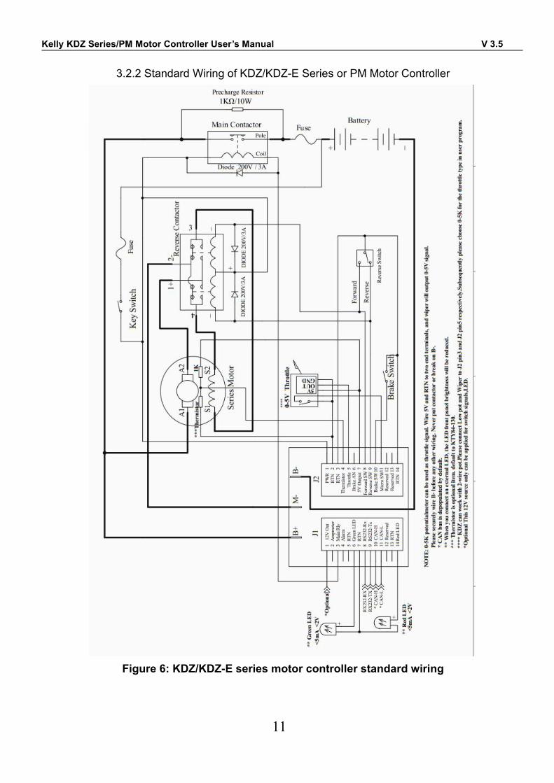
3.2.2 Standard Wiring of KDZ/KDZ-E Series or PM Motor Controller
Figure 6: KDZ/KDZ-E series motor controller standard wiring
Kelly KDZ Series/PM Motor Controller User’s Manual V 3.5
12
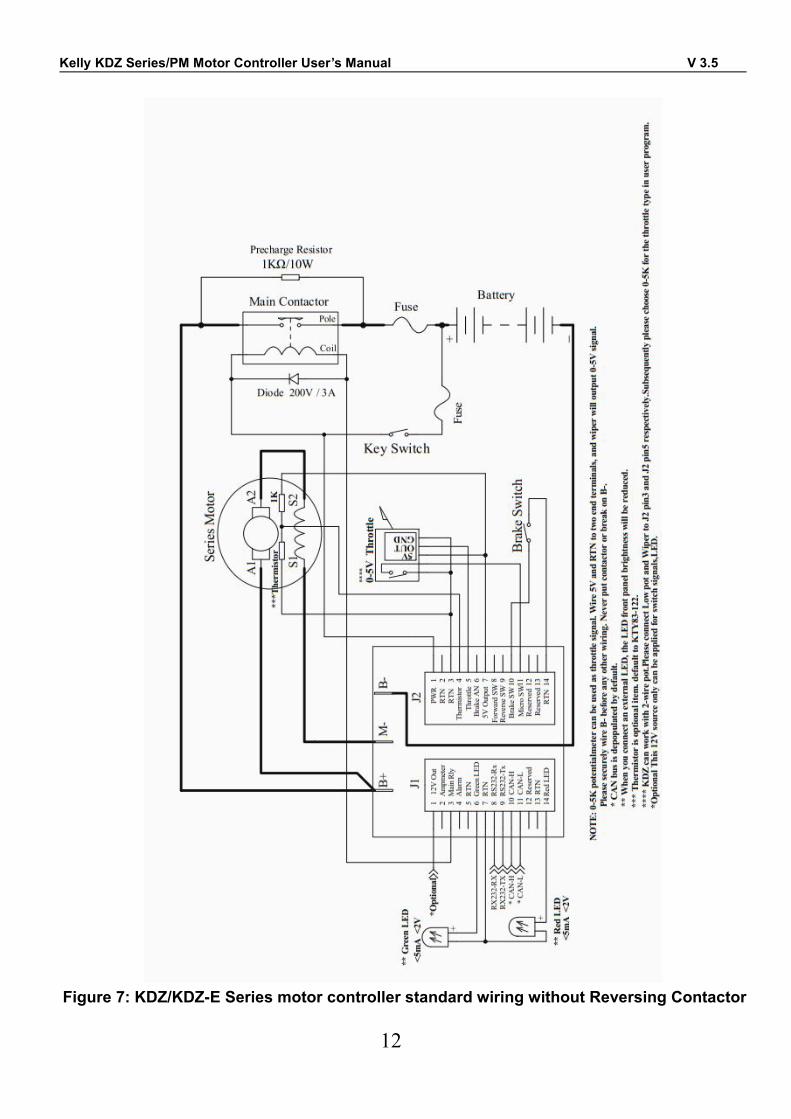
Figure 7: KDZ/KDZ-E Series motor controller standard wiring without Reversing Contactor
Kelly KDZ Series/PM Motor Controller User’s Manual V 3.5
13
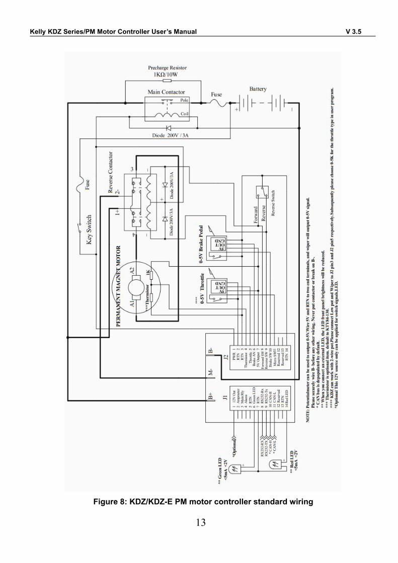
Figure 8: KDZ/KDZ-E PM motor controller standard wiring
Kelly KDZ Series/PM Motor Controller User’s Manual V 3.5
14
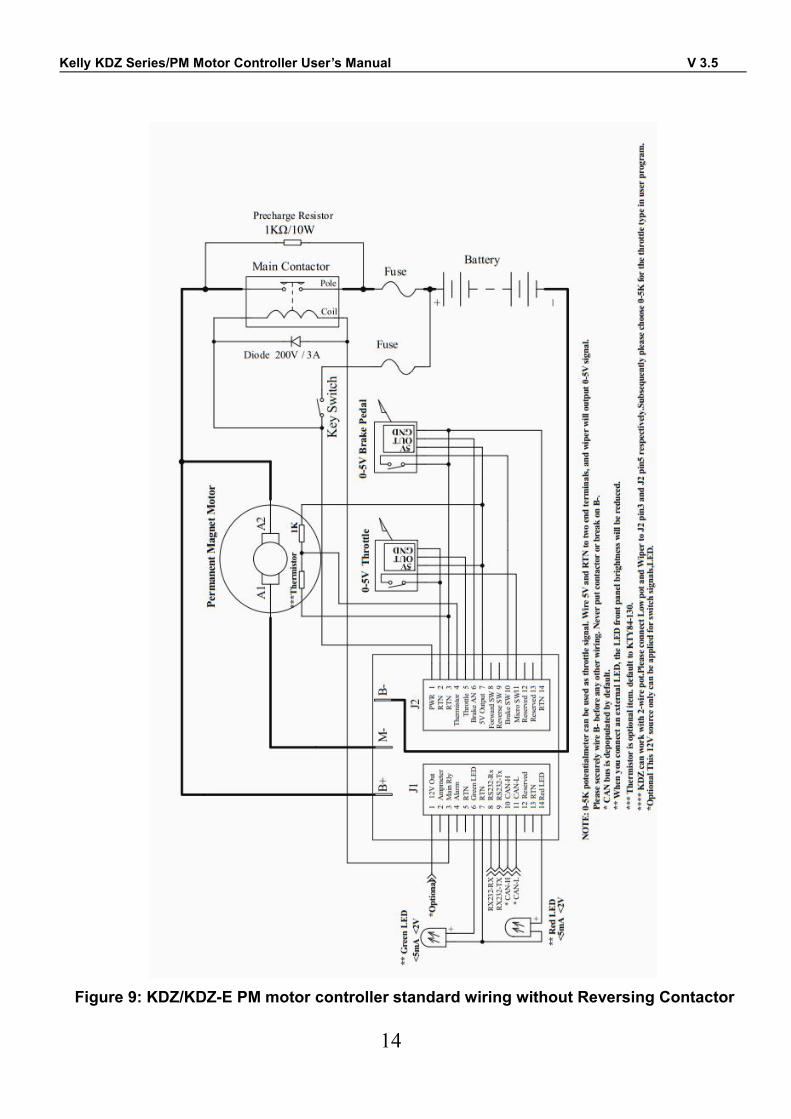
Figure 9: KDZ/KDZ-E PM motor controller standard wiring without Reversing Contactor
Kelly KDZ Series/PM Motor Controller User’s Manual V 3.5
15
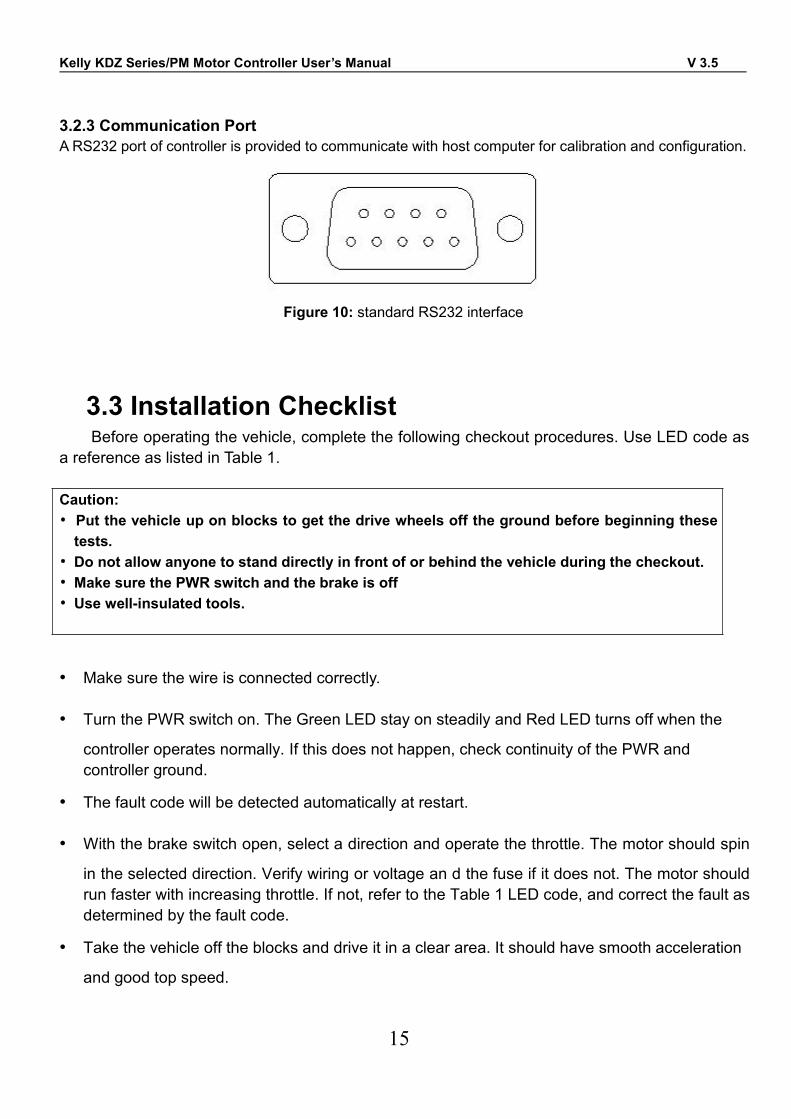
3.2.3 Communication PortA RS232 port of controller is provided to communicate with host computer for calibration and configuration.
Figure 10: standard RS232 interface
3.3 Installation ChecklistBefore operating the vehicle, complete the following checkout procedures. Use LED code as
a reference as listed in Table 1.
Caution:• Put the vehicle up on blocks to get the drive wheels off the ground before beginning thesetests.
• Do not allow anyone to stand directly in front of or behind the vehicle during the checkout.• Make sure the PWR switch and the brake is off• Use well-insulated tools.
• Make sure the wire is connected correctly.
• Turn the PWR switch on. The Green LED stay on steadily and Red LED turns off when the
controller operates normally. If this does not happen, check continuity of the PWR andcontroller ground.
• The fault code will be detected automatically at restart.
• With the brake switch open, select a direction and operate the throttle. The motor should spin
in the selected direction. Verify wiring or voltage an d the fuse if it does not. The motor shouldrun faster with increasing throttle. If not, refer to the Table 1 LED code, and correct the fault asdetermined by the fault code.
• Take the vehicle off the blocks and drive it in a clear area. It should have smooth acceleration
and good top speed.
Kelly KDZ Series/PM Motor Controller User’s Manual V 3.5
16
Chapter 4 MaintenanceThere are no user-serviceable parts inside the controllers. Do not attempt to open the
controller as this will void your warranty. However, periodic, exterior cleaning of the controllershould be carried out.
The controller is a high powered device. When working with any battery powered vehicle,proper safety precautions should be taken that include, but are not limited to, proper training,wearing eye protection, avoidance of loose clothing, hair and jewelry. Always use insulated tools.
4.1 CleaningAlthough the controller requires virtually no maintenance after properly installation, the
following minor maintenance is recommended in certain applications.• Remove power by disconnecting the battery, starting with battery positive.• Discharge the capacitors in the controller by connecting a load (such as a contactor coil or a
horn) across the controller’s B+ and B- terminals.• Remove any dirt or corrosion from the bus bar area. The controller should be wiped down with
a moist rag. Make sure it is dry before reconnecting the battery.• Make sure the connections to the bus bars, if fitted, are tight. To avoid physically stressing the
bus bars use two, well-insulated wrenches.
4.2 ConfigurationYou can configure the controller with a host computer through either an RS232 USB port.• Disconnect motor wiring from controller.• Do not connect B+, throttle and so on. The controller may display fault code in some
conditions, but it doesn't affect programming or configuration.• Use a straight through RS232 cable or USB Converter provided by Kelly to connect to a host
computer.• Provide >+18V to PWR (either J2 pin1). Wire power supply return to any RTN pin.
Download the free configuration software from:
http://www.kellycontroller.com/support.phpCaution:•Make certain that the motor is disconnected before trying to run the ConfigurationSoftware!•Configuration software will be regularly updated and published on the website. PleaseUpdate your Configuration Software regularly. You must uninstall the older versionbefore updating.
Kelly KDZ Series/PM Motor Controller User’s Manual V 3.5
17
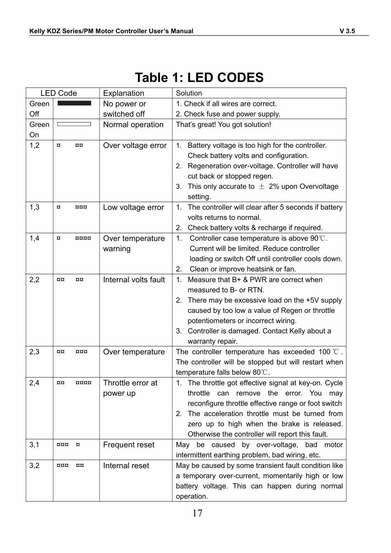
Table 1: LED CODESLED Code Explanation Solution
GreenOff
No power orswitched off
1. Check if all wires are correct.2. Check fuse and power supply.
GreenOn
Normal operation That’s great! You got solution!
1,2 ¤ ¤¤ Over voltage error 1. Battery voltage is too high for the controller.Check battery volts and configuration.
2. Regeneration over-voltage. Controller will havecut back or stopped regen.
3. This only accurate to ± 2% upon Overvoltagesetting.
1,3 ¤ ¤¤¤ Low voltage error 1. The controller will clear after 5 seconds if batteryvolts returns to normal.
2. Check battery volts & recharge if required.1,4 ¤ ¤¤¤¤ Over temperature
warning1. Controller case temperature is above 90℃.
Current will be limited. Reduce controllerloading or switch Off until controller cools down.
2. Clean or improve heatsink or fan.2,2 ¤¤ ¤¤ Internal volts fault 1. Measure that B+ & PWR are correct when
measured to B- or RTN.2. There may be excessive load on the +5V supply
caused by too low a value of Regen or throttlepotentiometers or incorrect wiring.
3. Controller is damaged. Contact Kelly about awarranty repair.
2,3 ¤¤ ¤¤¤ Over temperature The controller temperature has exceeded 100℃ .The controller will be stopped but will restart whentemperature falls below 80℃.
2,4 ¤¤ ¤¤¤¤ Throttle error atpower up
1. The throttle got effective signal at key-on. Cyclethrottle can remove the error. You mayreconfigure throttle effective range or foot switch
2. The acceleration throttle must be turned fromzero up to high when the brake is released.Otherwise the controller will report this fault.
3,1 ¤¤¤ ¤ Frequent reset May be caused by over-voltage, bad motorintermittent earthing problem, bad wiring, etc.
3,2 ¤¤¤ ¤¤ Internal reset May be caused by some transient fault condition likea temporary over-current, momentarily high or lowbattery voltage. This can happen during normaloperation.
Kelly KDZ Series/PM Motor Controller User’s Manual V 3.5
18
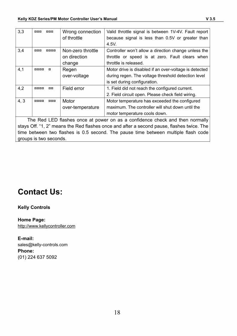
3,3 ¤¤¤ ¤¤¤ Wrong connectionof throttle
Valid throttle signal is between 1V-4V. Fault reportbecause signal is less than 0.5V or greater than4.5V.
3,4 ¤¤¤ ¤¤¤¤ Non-zero throttleon directionchange
Controller won’t allow a direction change unless thethrottle or speed is at zero. Fault clears whenthrottle is released.
4,1 ¤¤¤¤ ¤ Regenover-voltage
Motor drive is disabled if an over-voltage is detectedduring regen. The voltage threshold detection levelis set during configuration.
4,2 ¤¤¤¤ ¤¤ Field error 1. Field did not reach the configured current.2. Field circuit open. Please check field wiring.
4, 3 ¤¤¤¤ ¤¤¤ Motorover-temperature
Motor temperature has exceeded the configuredmaximum. The controller will shut down until themotor temperature cools down.
The Red LED flashes once at power on as a confidence check and then normallystays Off. “1, 2” means the Red flashes once and after a second pause, flashes twice. Thetime between two flashes is 0.5 second. The pause time between multiple flash codegroups is two seconds.
Contact Us:
Kelly Controls
Home Page:http://www.kellycontroller.com
E-mail:[email protected]:(01) 224 637 5092