Embed Size (px)
Citation preview

Single Energy Metal Artifact ReductionA Reliable Metal Management Tool in CT
Di Zhang, Ph.D.Clinical Collaborations Manager Toshiba America Medical Systems
Erin Angel, Ph.D.Senior Manager, Clinical Collaborations Toshiba America Medical Systems
There are often artifacts around metal objects when they are present in CT images. They appear as bright and dark streaks throughout the images and around the metal implant. These artifacts deteriorate the image quality and sometimes present themselves as band artifacts that obscure areas close to metal completely. Therefore they can drastically reduce the diagnostic value of CT images.
Common sources of metal artifacts include knee, hip, and shoulder prostheses, vessel clips and stents, cardiac pacemakers, dental fillings and tooth replacements, and metallic screws or rods within the body. They are usually made of titanium or stainless steel which are high density and high atomic number materials that are difficult for X-rays to penetrate. Beam hardening effect, photon starvation, scatter, and partial volume effects from these high density materials are the direct causes of metal artifacts.1 As a result of these artifacts, anatomies around the metallic materials may be rendered invisible or non-diagnostic.
Approximately 7 million Americans are living with hip or knee prosthesis.2 As the population continues to age, this percentage will likely become even higher. The need for improved metal artifact reduction (MAR) in CT continues to grow. Furthermore, due to interactions between metal and
magnetic fields, metal implants are generally considered a contraindication for Magnetic Resonance (MR) imaging.3 For this reason, CT is often used in place of MR for patients with metal implants. As CT and metal implant utilization continue to rise, metal artifact reduction has emerged as an important field of innovation.
Approaches to Reduce Metal Artifact
The fundamental causes of metal artifacts are beam hardening and photon starvation. Various approaches have been proposed in the past several decades to reduce CT metal artifacts. Attempts to suppress the artifacts without algorithmic modifications, such as expanding the CT number scale to make the streaks less obvious4, using higher kV or mA to increase the penetration of X-ray photons5, or using thin collimation and reduced Field Of View (FOV), can only alleviate the image quality issues to a limited degree. Therefore the majority of MAR approaches in fact use algorithmic methods. Although a few of the proposed methods only use images for the correction of metal artifact without involving raw projection data6, most have some manipulation on the raw projection data. In raw
2
data space, one pixel defect translates to a streak line in the corresponding reconstructed image. Therefore, it is much easier to manage the streak artifacts at the raw data level than in image space. These methods can be categorized as: dual energy approach, pure raw data correction approach, and iterative reconstruction approach.
Dual Energy ApproachDual energy CT has gained some clinical interests in the
past few years. By sampling an object using two different X-ray spectra, dual energy CT allows material decomposition which yields material-specific information, such as the characterization of urinary stones and visualization of gout tophi. In addition, based on the attenuation information obtained from two different spectra, the data set can be represented by a combination of two basis materials, which can be then used to generate virtual monochromatic images for specific photon energies, e.g., keV images. Due to the pseudo-energetic nature of keV beams, these images are theoretically free of beam hardening artifacts, which are a large component of metal artifacts. Therefore dual energy techniques have been used to mitigate metal artifacts in recent years.7
However, dual energy solutions often do not perform well for metal artifact reduction because it addresses only beam hardening effects and does not address other sources of metal artifact such as photon starvation and scatter. Several studies have reported that, although dual energy MAR decreases metal artifacts to some extent, it can have a negative impact on the image quality, such as introducing new streaks that obscure anatomical structures8, or compromising Contrast to Noise Ratio (CNR).9
Pure Raw Data Correction ApproachThe idea of sinogram-based raw data correction is almost
as old as CT technology itself. The first algorithm developed to correct CT metal artifact was published in 1978.10 Since then numerous variations and modifications of the method were developed. The fundamental principle of the raw data correction approach is to identify the data in the sinogram that is corrupted by high density objects in the X-ray beam and replace these values with reasonable estimates. The two key components of such an algorithm are the identification of corrupted data, and the estimation of the corrupted data for replacement.
There are two main methods for raw data identification: direct detection from projection and forward projection of
segmented metal image. The first method identifies the raw data bins affected by metal based on higher intensities due to high attenuation in metallic objects. The second method segments the FBP images to obtain metal mask images, which are then forward projected to define metal traces in raw data. The latter method has gained more popularity because it is often difficult to distinguish projections with and without metal in X-ray beam directly from raw data.
Once the metal affected projection data bins are identified, there are many approaches to estimate the raw data to replace the metal corrupted values, including linear interpolation, sinogram normalization, tissue-class modeling, and many others.11, 12, 13 Among these methods, Linear Interpolation Metal Artifact Reduction (LIMAR) is a classic algorithm which forward projects segmented metal to identify corrupted raw data bins and then replace all values from these bins by linear interpolation. The corrected raw data is reconstructed to obtain images. And finally the segmented metal is inserted back into the images.11
The effectiveness of artifact reduction highly depends on the estimation of the raw data values. Any sharp transition between the original projection bins and estimated projection bins would result in new streak artifacts.14 In addition, the data loss near the metal edge that is not recoverable by the estimation of raw data values results in blurring. Because in clinical reality the size and location of metal materials vary significantly, it is very challenging to completely eliminate the streak artifacts and blurring for all clinical cases.
Iterative Reconstruction ApproachFiltered back-projection (FBP) algorithms have been used
for clinical CT imaging for decades. It was not until recent years that commercial iterative reconstruction technologies became routinely available. One of the assumptions used in FBP algorithm is that the projection data are consistent and complete, which is clearly violated when a high attenuating material, such as metal, is in the X-ray beam. Therefore, iterative reconstruction algorithms, which do not make these assumptions, can yield better results with less metal caused artifacts. The basic principle of iterative reconstruction is to derive an initial guess of the final image, re-project the image to raw data space and compare it with the original raw data to generate a corrective image, apply the correction, and repeat the process until the difference reaches a pre-defined minimum. There have been a variety of iterative reconstruction methods developed for MAR.15,16

3
Although an iterative reconstruction approach theoretically can handle the streaks very well, it requires extensive knowledge about the CT system configuration. In addition, the associated computation time for full iterative reconstruction can be clinically prohibitive. A method that effectively mitigates metal artifacts to a clinically acceptable level without affecting the workflow is in great need in solving metal problems in CT imaging.
SEMAR™
Single Energy Metal Artifact Reduction (SEMAR) is a raw data based technique that incorporates the gradient correction features of iterative reconstruction with clinically reasonable reconstruction times.
PrincipleIn order to circumvent the limitation of pure raw
data based approaches, where the transitions between
original raw data and estimated raw data bins create
new streaks and blurring, SEMAR generates a prior image
from the metal subtracted sinogram, classifies the data
by identifying intensity gradients, and applies a gradient
intensity optimization via forward projection. This allows
the algorithm to replace raw data bins corrupted by
metallic objects with more accurate estimations while still
maintaining clinically reasonable reconstruction times.
A description of the SEMAR algorithm is shown in Figure 1
and can be described as follows: The original raw projection
data undergoes filtered back-projection to generate an
image series. Metal is segmented from this image to
Original Projection Data Metal-Only Projection Data Metal-Removed Projection Data
Forward Projection
Forward ProjectionAddition of Metal
SEMAR image
Extracted Metal Further Elimination of Metal
Back ProjectionBack Projection
Original Image
Start
Bac
k P
roje
ctio
n
Figure 1 SEMAR algorithm.
4
generate a metal-only image. The metal-only image is forward projected to identify the metal trace.
The metal affected data bins in the sinogram are then estimated using a proprietary algorithm. The metal-free sinogram undergoes filtered back-projection to generate a prior image. The prior image undergoes a gradient optimization process. This process smooths the transition between raw data bins while maintaining image edge content. Using filtered back-projection once more, an image series with metallic components removed is generated. The previously extracted metallic components are inserted to the reconstructed images to solve for the final SEMAR image. This process smooths the transition between raw data bins while maintaining image edge content. Using filtered back-projection once more, an image series with metallic components removed is generated. The previously
extracted metallic components are inserted to the reconstructed images to solve for the final SEMAR image.
Clinical ApplicationSEMAR mitigates CT artifacts from metal and provides
improved visualization of the soft tissue structures surrounding metal objects. SEMAR reduces artifacts due to spine fixation devices, bone prosthesis, screws, bolts, coils, stents, pacemakers, dental prosthesis, and other internal metallic components. Optimal artifact reduction effects may not be obtained for the soft tissues inside and immediately proximal to small metal objects with complicated shapes such as coils and stents. For this reason, the SEMAR processed images should be reviewed with the original images at the time of diagnosis.
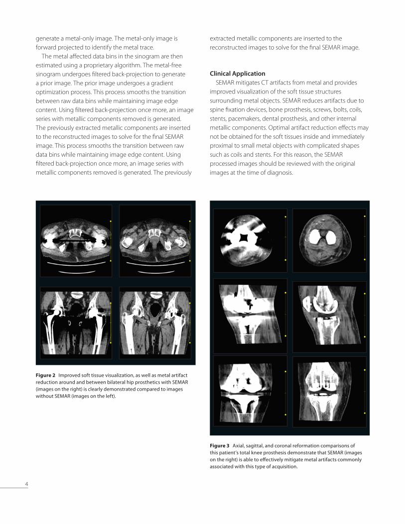
Figure 2 Improved soft tissue visualization, as well as metal artifact reduction around and between bilateral hip prosthetics with SEMAR (images on the right) is clearly demonstrated compared to images without SEMAR (images on the left).
Figure 3 Axial, sagittal, and coronal reformation comparisons of this patient’s total knee prosthesis demonstrate that SEMAR (images on the right) is able to effectively mitigate metal artifacts commonly associated with this type of acquisition.

5
Figure 4 Sagittal and coronal images without SEMAR (left) of a spine fixation compared to images with SEMAR (right). Improvements in visualization, and reduction of metal artifacts may be appreciated in the image sets reconstructed with SEMAR.
Figure 5 Multi-planar reconstructions are of much higher quality with SEMAR (right) and allow visualization of the adjacent structures, e.g. in this case the neck of the aneurysm, as compared to the prior study performed on a different system, where severe artifacts impeded evaluation of the volume rendered image produced in the similar projection (left).

6
Conclusion
Metal management has been a challenging task in CT imaging. SEMAR is a sophisticated algorithm that circumvents the limitations of traditional MAR methods and effectively minimizes metal artifacts. Compared to dual energy solutions, SEMAR addresses image defects not only from beam hardening effects but also from photon
starvation and scatter. In addition, SEMAR does not require
a dedicated dual energy acquisition and can be applied to
any routine scan or even retrospectively in raw data. Streak
artifacts from metallic implants are minimized, resulting in
drastic artifact reduction. Finally, SEMAR is workflow friendly
and can be set in the scan protocol so the reconstructions
are fully automatic, requiring no additional operator input.
Figure 6 Sagittal and axial reformations show that metal artifact streaking from the endovascular coil in the images reconstructed without SEMAR (left) obscure visualization of adjacent anatomy in this Circle of Willis study. Images with SEMAR (right) significantly improve visualization and reduce metal artifact.

7
1. B. De Man, J. Nuyts, P. Dupont, G. Marchal and a. P. Suetens, “Metal,” IEEE Trans. Nucl. Sci, no. 46, pp. 691-696, 1999.
2. Kremers HM, Larson DR, Crowson CS, et al. Prevalence of Total Hip and Knee Replacement in the United States. J Bone Joint Surg Am 2015;97:1386–97.
3. R. M. S. Joemai, P. W. d. Bruin, W. J. H. Veldkamp and J. Geleijns, “Metal artifact reduction for CT: Development, implementation, and clinical comparison of a generic and a scanner-specific technique,” Medical Physics, no. 39, p. 1125, 2012.
4. C. Coolens and P. J. Childs, “Calibration of CT Hounsfield units for radiotherapy treatment planning of patients with metallic hip prostheses: The use of the extended CT-scale,” Phys. Med. Biol., vol. 48, pp. 1591-1603, 2003.
5. S. G. Moon, S. H. Hong, J. Y. Choi, W. S. Jun, H. G. Kang, H. S. Kim and H. S. Kang, “Metal artifact reduction by the alteration of technical factors in multidetector computed tomography: A 3-dimensional quantitative assessment,” J. Compute. Assist. Tomogr., vol. 32, pp. 630-633, 2008.
6. V.Naranjo, R.Llorens, M.Alcaniz and F. Lopez-Mir, “Metal artifact reduction in dental CT images using polar mathematical morphology,” Comput. Methods Programs Biomed, vol. 102, pp. 64-74, 2011.
7. E.Pessis, R.Campagna, J.M.Sverzut, F.Bach, M.Rodallec, H.Guerini, A.Feydy and J.L.Drapé, “Virtual monochromatic spectral imaging with fast kilovoltage switching: reduction of metal artifacts at CT,” Radiographics, vol. 33, no. 2, pp. 573-83, 2013.
8. S.C.Han, Y.E.Chung, Y.H.Lee, K.K.Park, M.J.Kim and K.W.Kim, “Metal artifact reduction software used with abdominopelvic dual-energy CT of patients with metal hip prostheses: assessment of image quality and clinical feasibility,” American Journal of Roentgenology, vol. 203, no. 4, pp. 788-95, 2014.
9. S.Kuchenbecker, S.Faby and M. M. M. S.Sawall, “Dual energy CT: how well can pseudo-monochromatic imaging reduce metal artifacts?,” Medical Physics, vol. 42, no. 2, pp. 1023-36, 2015.
10. R.M.Lewitt and R.H.T.Bates, “Image reconstruction from projections: III projection completion methods (theory),” Optik, vol. 50, pp. 189-204, 1978.
11. W.A.Kalender, R.Hebel and J.Ebersberger, “Reduction of CT artifacts caused by metallic implants,” Radiology, vol. 164, pp. 576-577, 1987.
12. E.Meyer, R.Raupach, M.Lell, B.Schmidt and M.Kachelriess, “Normalized metal artifact reduction (NMAR) in computed tomography,” Medical Physics, vol. 37, pp. 5482-5493, 2010.
13. M.Bal and L.Spies, “Metal artifact reduction in CTusing tissue-class modeling and adaptive prefiltering,” Medical Physics, vol. 33, pp. 2852-2859, 2006.
14. N.Subhas, A. Primak, N.A.Obuchowsk, A.Gupta, J.M.Polster, A. K. A and J.P.Iannotti, “Iterative metal artifact reduction: evaluation and optimization of technique.,” Skeletal. Radiol., vol. 43, pp. 1729-35, 2014.
15. B. Man, J.Nuyts, P. Dupont, G. Marchal and P. Suetens, “Reduction of metal streak artifacts in X-ray computed tomography using a transmission maximum a posteriori algorithm,” IEEE Trans. Nucl. Sci., vol. 47, pp. 977-981, 2000.
16. J. Hsieh, R.C.Molthen, C.A.Dawson and R.H.Johnson, “An iterative approach to the beam hardening correction in cone beam CT,” Medical Physics, vol. 27, pp. 23-29, 2000.
References
©Toshiba America Medical Systems 2017. All rights reserved. Design and specifications are subject to change without notice.Aplio and Made for Life are trademarks of Toshiba Medical Systems Corporation.Google+ logo and YouTube logo are trademarks of Google Inc. TWITTER, TWEET, RETWEET and the Twitter logo are trademarks of Twitter, Inc. or its affiliates. LinkedIn, the LinkedIn logo, the IN logo and InMail are registered trademarks or trademarks of LinkedIn Corporation and its affiliates in the United States and/or other countries.
TOSHIBA AMERICA MEDICAL SYSTEMS, INC. 2441 Michelle Drive, Tustin CA 92780 | 800.421.1968
CTWP12532US MCACT0317EB
Follow us: www.Medical.Toshiba.com @ToshibaMedical +Toshiba Medical Toshiba America Medical Toshiba Medical
Computed Tomography

![pc pc 2012 - examenbac.com · NS28 / (aq) (s) (s) (aq) 10 —2 + = ] (aq) i 4(aq) mol. L; 1 + = ' (aq) i (aq) 4(aq) 7m +Cu2+ + 4....*àA.Z = 5.1036 F = 9, 65.104 C.mol- —2](https://img.pdfslide.us/doc/110x75/5b9bedcb09d3f29b498bc24a/pc-pc-2012-ns28-aq-s-s-aq-10-2-aq-i-4aq-mol-l-1-.jpg)