Embed Size (px)
Citation preview
Download and Define Parameters in Tuning Adapter Configuration File
Overview
Introduction
The Cisco® STA1520 tuning adapter (tuning adapter), when connected to a
Unidirectional Digital Cable Product (UDCP), provides access to switched digital
broadcasts from a service provider. The tuning adapter connects to the UDCP
host device via a USB interface.
Within SARA environments, the tuning adapter, by default, obtains its channel
map and other switched digital video (SDV) specific configuration information
through the traditional DNCS and SARA Application Server methods, including
the SAM Service Table, Display Channel Table, Split Channel Table, to name a
few.
However, for non-SARA environments, a specific BFS configuration file for the
tuning adapter must be generated using a special utility. The service provider
may, optionally, provide the tuning adapter configuration file in SARA
environments as well to override the default tuning adapter configuration if
desired, but this is not required.
Purpose
This document provides an overview of the tuning adapter configuration file and
includes instructions for creating the output file using the file configuration
utility.
Scope
The contents of this document apply to customers deploying tuning adapters
within non-SARA environments. The instructions in this document are optional
for customers that use the traditional DNCS and SARA Application Server within
SARA environments.
2 4025013 Rev B
Overview
When Should This Procedure be Performed?
Initially, this procedure should be performed prior to deploying the tuning
adapters in the service provider's network. After initial deployment, this
procedure should be repeated whenever the following changes are made:
a planned change to the channel lineup
migrating broadcast channels to switched channels (or migrating switched channels to broadcast channels)
modifying configurable parameters for SDV
Note: We recommend that service providers perform this procedure during a
maintenance window.
Audience
This guide is written for test engineers and cable system administrators
responsible for the configuration and deployment of the tuning adapter
configuration file. [
Document Version
This is the first formal release of this document.
4025013 Rev B 3
Tuning Adapter Configuration File: An Overview
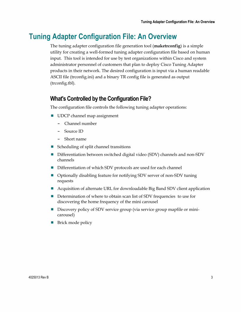
Tuning Adapter Configuration File: An Overview The tuning adapter configuration file generation tool (maketrconfig) is a simple
utility for creating a well-formed tuning adapter configuration file based on human
input. This tool is intended for use by test organizations within Cisco and system
administrator personnel of customers that plan to deploy Cisco Tuning Adapter
products in their network. The desired configuration is input via a human readable
ASCII file (trconfig.ini) and a binary TR config file is generated as output
(trconfig.tbl).
What's Controlled by the Configuration File?
The configuration file controls the following tuning adapter operations:
UDCP channel map assignment
- Channel number
- Source ID
- Short name
Scheduling of split channel transitions
Differentiation between switched digital video (SDV) channels and non-SDV channels
Differentiation of which SDV protocols are used for each channel
Optionally disabling feature for notifying SDV server of non-SDV tuning requests
Acquisition of alternate URL for downloadable Big Band SDV client application
Determination of where to obtain scan list of SDV frequencies to use for discovering the home frequency of the mini carousel
Discovery policy of SDV service group (via service group mapfile or mini-carousel)
Brick mode policy
4 4025013 Rev B
Tuning Adapter Configuration File: An Overview
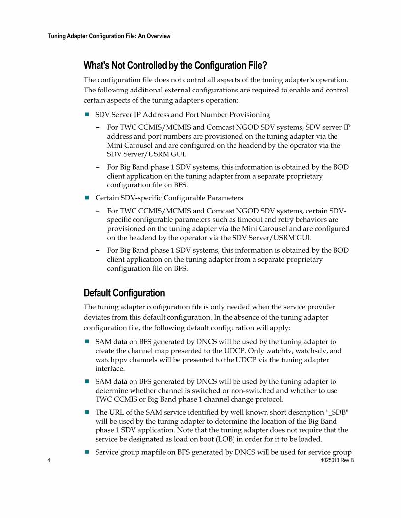
What's Not Controlled by the Configuration File?
The configuration file does not control all aspects of the tuning adapter's operation.
The following additional external configurations are required to enable and control
certain aspects of the tuning adapter's operation:
SDV Server IP Address and Port Number Provisioning
- For TWC CCMIS/MCMIS and Comcast NGOD SDV systems, SDV server IP address and port numbers are provisioned on the tuning adapter via the Mini Carousel and are configured on the headend by the operator via the SDV Server/USRM GUI.
- For Big Band phase 1 SDV systems, this information is obtained by the BOD client application on the tuning adapter from a separate proprietary configuration file on BFS.
Certain SDV-specific Configurable Parameters
- For TWC CCMIS/MCMIS and Comcast NGOD SDV systems, certain SDV-specific configurable parameters such as timeout and retry behaviors are provisioned on the tuning adapter via the Mini Carousel and are configured on the headend by the operator via the SDV Server/USRM GUI.
- For Big Band phase 1 SDV systems, this information is obtained by the BOD client application on the tuning adapter from a separate proprietary configuration file on BFS.
Default Configuration
The tuning adapter configuration file is only needed when the service provider
deviates from this default configuration. In the absence of the tuning adapter
configuration file, the following default configuration will apply:
SAM data on BFS generated by DNCS will be used by the tuning adapter to create the channel map presented to the UDCP. Only watchtv, watchsdv, and watchppv channels will be presented to the UDCP via the tuning adapter interface.
SAM data on BFS generated by DNCS will be used by the tuning adapter to determine whether channel is switched or non-switched and whether to use TWC CCMIS or Big Band phase 1 channel change protocol.
The URL of the SAM service identified by well known short description "_SDB" will be used by the tuning adapter to determine the location of the Big Band phase 1 SDV application. Note that the tuning adapter does not require that the service be designated as load on boot (LOB) in order for it to be loaded.
Service group mapfile on BFS generated by DNCS will be used for service group
4025013 Rev B 5
Tuning Adapter Configuration File: An Overview
discovery
For watchsdv channels, the TWC MCMIS compliant in-band mini carousel will be used to obtain the IP address and port number of the SDV server or USRM, SDV configuration parameters, and tuning information of all active SDV programs.
SDV Mini Carousel Discovery files on BFS generated by the DNCS will be used for in-band mini carousel discovery
CCMIS select request messages will be sent to the SDV Server for non-SDV channels as well as SDV channels
Tuning adapter brick mode policy is determined based on entitlement information in the DHCT global configuration file on BFS generated by the SARA Application Server.
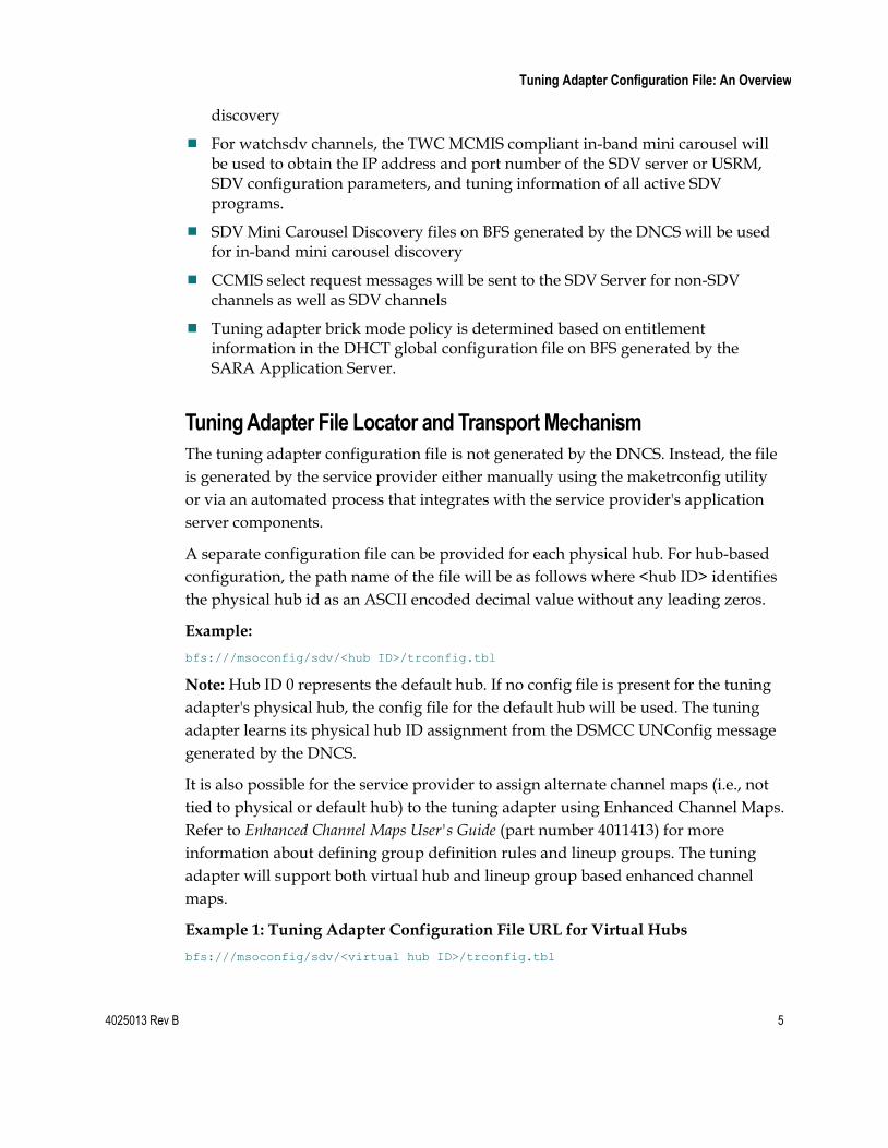
Tuning Adapter File Locator and Transport Mechanism
The tuning adapter configuration file is not generated by the DNCS. Instead, the file
is generated by the service provider either manually using the maketrconfig utility
or via an automated process that integrates with the service provider's application
server components.
A separate configuration file can be provided for each physical hub. For hub-based
configuration, the path name of the file will be as follows where <hub ID> identifies
the physical hub id as an ASCII encoded decimal value without any leading zeros.
Example:
bfs:///msoconfig/sdv/<hub ID>/trconfig.tbl
Note: Hub ID 0 represents the default hub. If no config file is present for the tuning
adapter's physical hub, the config file for the default hub will be used. The tuning
adapter learns its physical hub ID assignment from the DSMCC UNConfig message
generated by the DNCS.
It is also possible for the service provider to assign alternate channel maps (i.e., not
tied to physical or default hub) to the tuning adapter using Enhanced Channel Maps.
Refer to Enhanced Channel Maps User's Guide (part number 4011413) for more
information about defining group definition rules and lineup groups. The tuning
adapter will support both virtual hub and lineup group based enhanced channel
maps.
Example 1: Tuning Adapter Configuration File URL for Virtual Hubs
bfs:///msoconfig/sdv/<virtual hub ID>/trconfig.tbl
6 4025013 Rev B
Tuning Adapter Configuration File: An Overview
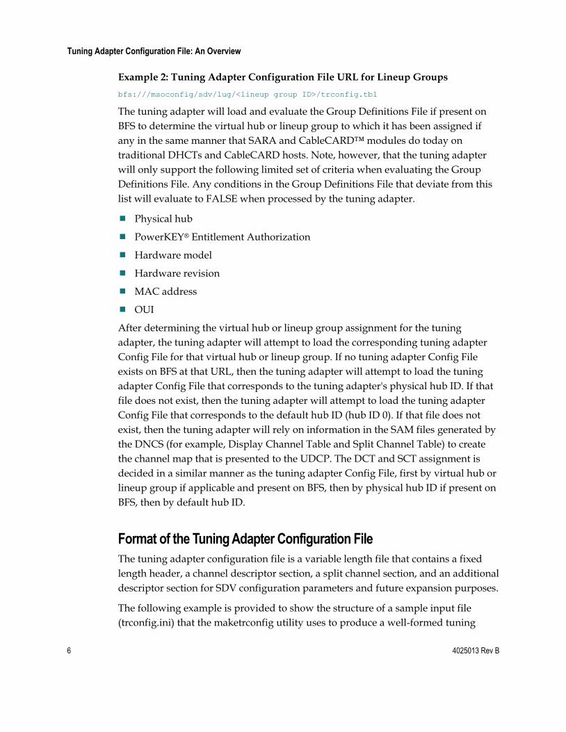
Example 2: Tuning Adapter Configuration File URL for Lineup Groups
bfs:///msoconfig/sdv/lug/<lineup group ID>/trconfig.tbl
The tuning adapter will load and evaluate the Group Definitions File if present on
BFS to determine the virtual hub or lineup group to which it has been assigned if
any in the same manner that SARA and CableCARD™ modules do today on
traditional DHCTs and CableCARD hosts. Note, however, that the tuning adapter
will only support the following limited set of criteria when evaluating the Group
Definitions File. Any conditions in the Group Definitions File that deviate from this
list will evaluate to FALSE when processed by the tuning adapter.
Physical hub
PowerKEY® Entitlement Authorization
Hardware model
Hardware revision
MAC address
OUI
After determining the virtual hub or lineup group assignment for the tuning
adapter, the tuning adapter will attempt to load the corresponding tuning adapter
Config File for that virtual hub or lineup group. If no tuning adapter Config File
exists on BFS at that URL, then the tuning adapter will attempt to load the tuning
adapter Config File that corresponds to the tuning adapter's physical hub ID. If that
file does not exist, then the tuning adapter will attempt to load the tuning adapter
Config File that corresponds to the default hub ID (hub ID 0). If that file does not
exist, then the tuning adapter will rely on information in the SAM files generated by
the DNCS (for example, Display Channel Table and Split Channel Table) to create
the channel map that is presented to the UDCP. The DCT and SCT assignment is
decided in a similar manner as the tuning adapter Config File, first by virtual hub or
lineup group if applicable and present on BFS, then by physical hub ID if present on
BFS, then by default hub ID.
Format of the Tuning Adapter Configuration File
The tuning adapter configuration file is a variable length file that contains a fixed
length header, a channel descriptor section, a split channel section, and an additional
descriptor section for SDV configuration parameters and future expansion purposes.
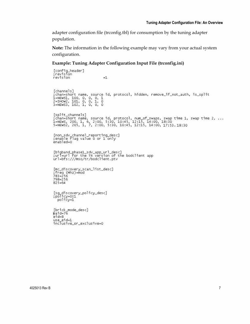
The following example is provided to show the structure of a sample input file
(trconfig.ini) that the maketrconfig utility uses to produce a well-formed tuning
4025013 Rev B 7
Tuning Adapter Configuration File: An Overview
adapter configuration file (trconfig.tbl) for consumption by the tuning adapter
population.
Note: The information in the following example may vary from your actual system
configuration.
Example: Tuning Adapter Configuration Input File (trconfig.ini)
8 4025013 Rev B
Install the maketrconfig Utility
Install the maketrconfig Utility The maketrconfig utility is the name of the tuning adapter configuration file
generation tool. This utility can be used on either the Windows OS or the UNIX OS.
Complete the following steps to install the maketrconfig utility on your computer.
1 Copy the maketrconfig executable file in any folder on your UNIX or Windows
PC.
2 Create a trconfig.ini file and place it in the same folder as the maketrconfig
executable file.
3 Run the executable file.
Note: Should you encounter errors when running the tool, the errors are logged
in the trconfig.log file for reference.
4025013 Rev B 9
Add the Tuning Adapter Configuration File to the DNCS
Add the Tuning Adapter Configuration File to the DNCS In this procedure, you will add the tuning adapter configuration file (trconfig.ini) to
the DNCS.
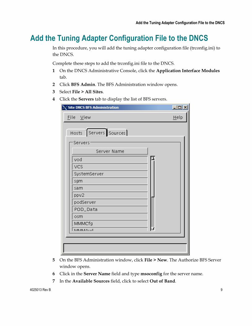
Complete these steps to add the trconfig.ini file to the DNCS.
1 On the DNCS Administrative Console, click the Application Interface Modules
tab.
2 Click BFS Admin. The BFS Administration window opens.
3 Select File > All Sites.
4 Click the Servers tab to display the list of BFS servers.
5 On the BFS Administration window, click File > New. The Authorize BFS Server
window opens.
6 Click in the Server Name field and type msoconfig for the server name.
7 In the Available Sources field, click to select Out of Band.
10 4025013 Rev B
Add the Tuning Adapter Configuration File to the DNCS
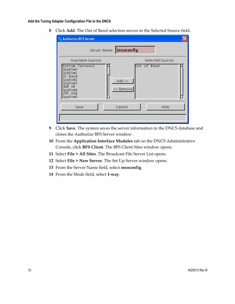
8 Click Add. The Out of Band selection moves to the Selected Source field.
9 Click Save. The system saves the server information in the DNCS database and
closes the Authorize BFS Server window.
10 From the Application Interface Modules tab on the DNCS Administrative
Console, click BFS Client. The BFS Client Sites window opens.
11 Select File > All Sites. The Broadcast File Server List opens.
12 Select File > New Server. The Set Up Server window opens.
13 From the Server Name field, select msoconfig.
14 From the Mode field, select 1-way.
4025013 Rev B 11
Add the Tuning Adapter Configuration File to the DNCS
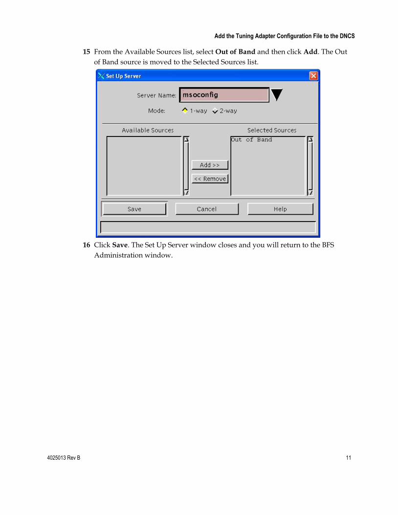
15 From the Available Sources list, select Out of Band and then click Add. The Out
of Band source is moved to the Selected Sources list.
16 Click Save. The Set Up Server window closes and you will return to the BFS
Administration window.
12 4025013 Rev B
Add the Tuning Adapter Configuration File to the DNCS
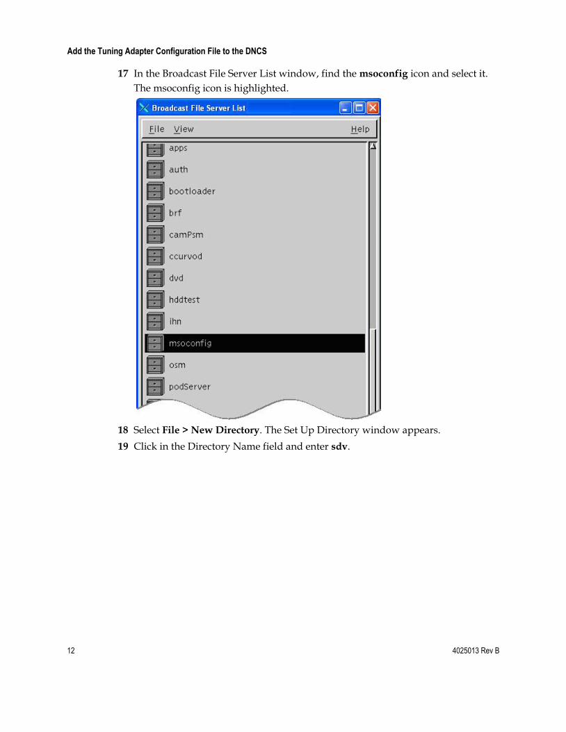
17 In the Broadcast File Server List window, find the msoconfig icon and select it.
The msoconfig icon is highlighted.
18 Select File > New Directory. The Set Up Directory window appears.
19 Click in the Directory Name field and enter sdv.
4025013 Rev B 13
Add the Tuning Adapter Configuration File to the DNCS
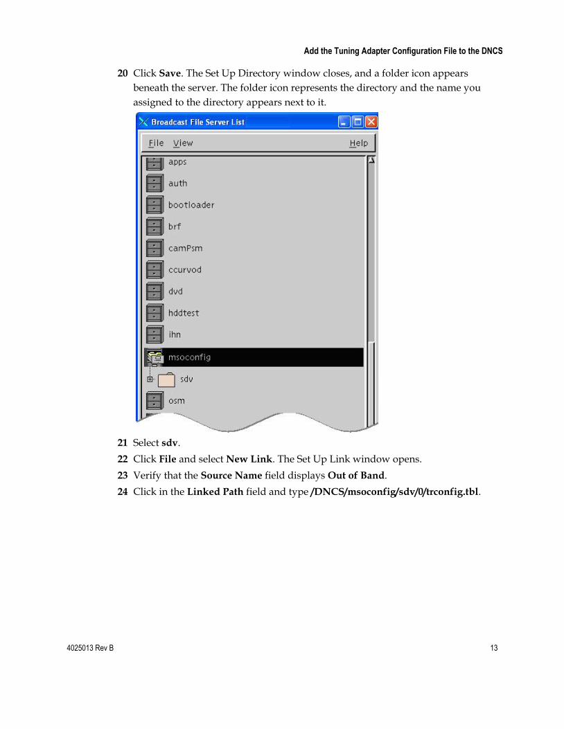
20 Click Save. The Set Up Directory window closes, and a folder icon appears
beneath the server. The folder icon represents the directory and the name you
assigned to the directory appears next to it.
21 Select sdv.
22 Click File and select New Link. The Set Up Link window opens.
23 Verify that the Source Name field displays Out of Band.
24 Click in the Linked Path field and type /DNCS/msoconfig/sdv/0/trconfig.tbl.
14 4025013 Rev B
Add the Tuning Adapter Configuration File to the DNCS
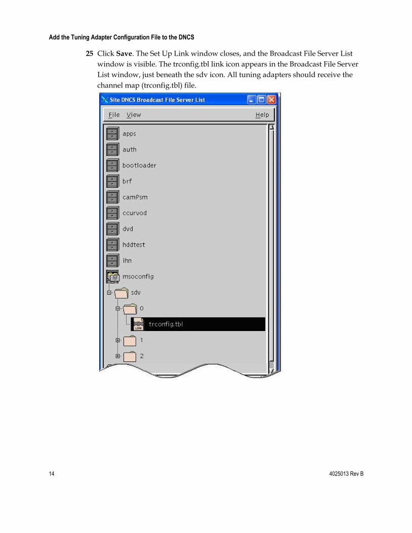
25 Click Save. The Set Up Link window closes, and the Broadcast File Server List
window is visible. The trconfig.tbl link icon appears in the Broadcast File Server
List window, just beneath the sdv icon. All tuning adapters should receive the
channel map (trconfig.tbl) file.
4025013 Rev B 15
Edit the trconfig.ini File
Edit the trconfig.ini File Occasionally, due to changes such as channel lineup changes, migrating channels
from broadcast to switched (or vice versa), or modifying SDV parameters, you may
need to make changes to the trconfig.ini file. Use the guidelines in this section for
editing the configuration file.
Important: Editing the trconfig.ini file does not automatically result in the updated
configuration being published to the tuning adapter population. The provider must
first run the maketrconfig utility and replace the outgoing tuning adapter
configuration file on the BFS with the new trconfig.tbl file in order for changes to
take effect. Therefore, we recommend that service providers replace the trconfg.tbl
file on the BFS during a maintenance window.
File Structure: Overview
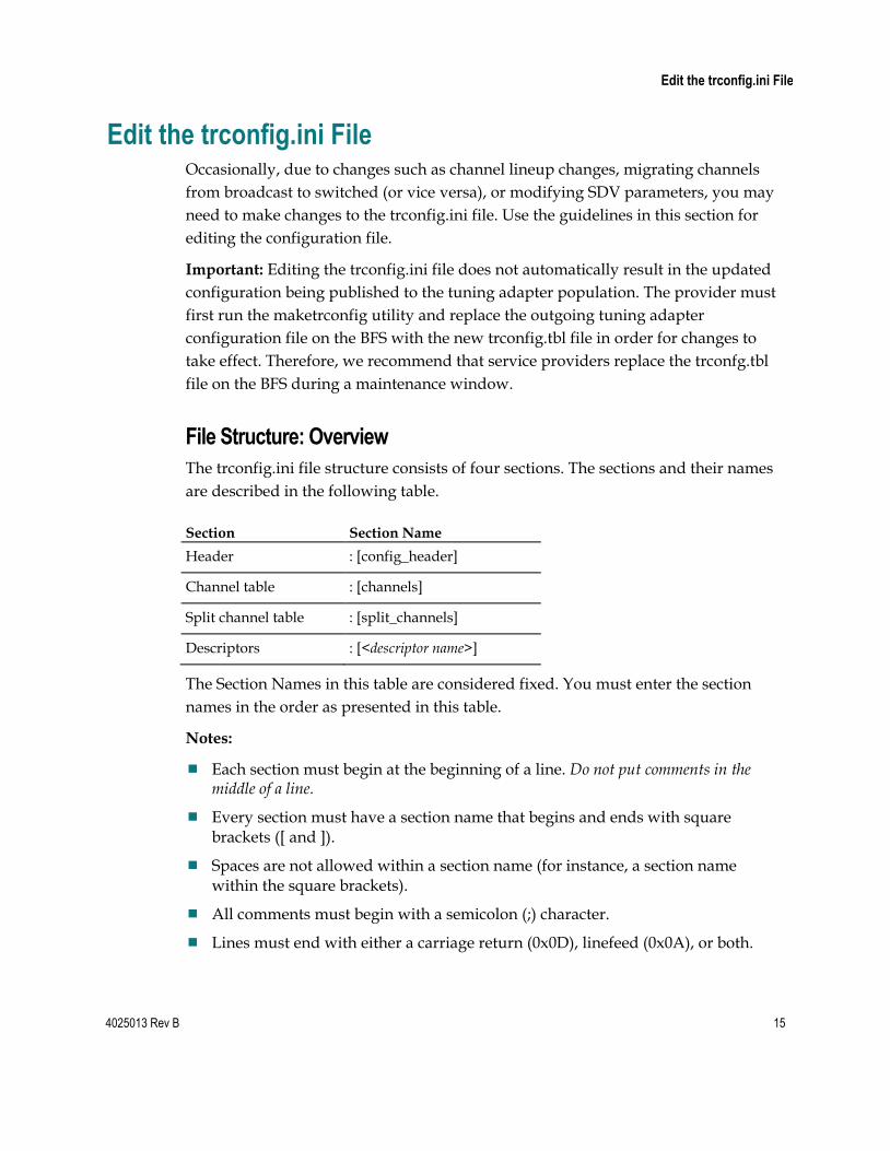
The trconfig.ini file structure consists of four sections. The sections and their names
are described in the following table.
Section Section Name
Header : [config_header]
Channel table : [channels]
Split channel table : [split_channels]
Descriptors : [<descriptor name>]
The Section Names in this table are considered fixed. You must enter the section
names in the order as presented in this table.
Notes:
Each section must begin at the beginning of a line. Do not put comments in the middle of a line.
Every section must have a section name that begins and ends with square brackets ([ and ]).
Spaces are not allowed within a section name (for instance, a section name within the square brackets).
All comments must begin with a semicolon (;) character.
Lines must end with either a carriage return (0x0D), linefeed (0x0A), or both.
16 4025013 Rev B
Edit the trconfig.ini File
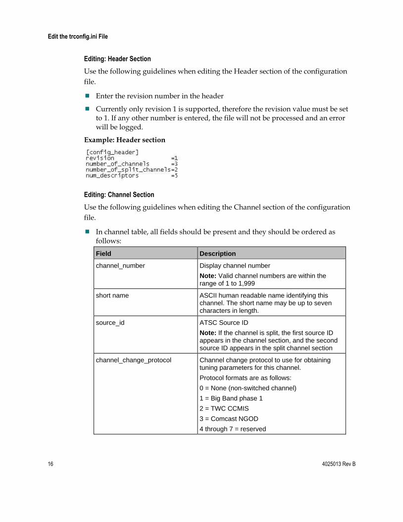
Editing: Header Section
Use the following guidelines when editing the Header section of the configuration
file.
Enter the revision number in the header
Currently only revision 1 is supported, therefore the revision value must be set to 1. If any other number is entered, the file will not be processed and an error will be logged.
Example: Header section
Editing: Channel Section
Use the following guidelines when editing the Channel section of the configuration
file.
In channel table, all fields should be present and they should be ordered as follows:
Field Description
channel_number Display channel number
Note: Valid channel numbers are within the range of 1 to 1,999
short name ASCII human readable name identifying this channel. The short name may be up to seven characters in length.
source_id ATSC Source ID
Note: If the channel is split, the first source ID appears in the channel section, and the second source ID appears in the split channel section
channel_change_protocol Channel change protocol to use for obtaining tuning parameters for this channel.
Protocol formats are as follows:
0 = None (non-switched channel)
1 = Big Band phase 1
2 = TWC CCMIS
3 = Comcast NGOD
4 through 7 = reserved
4025013 Rev B 17
Edit the trconfig.ini File
Field Description
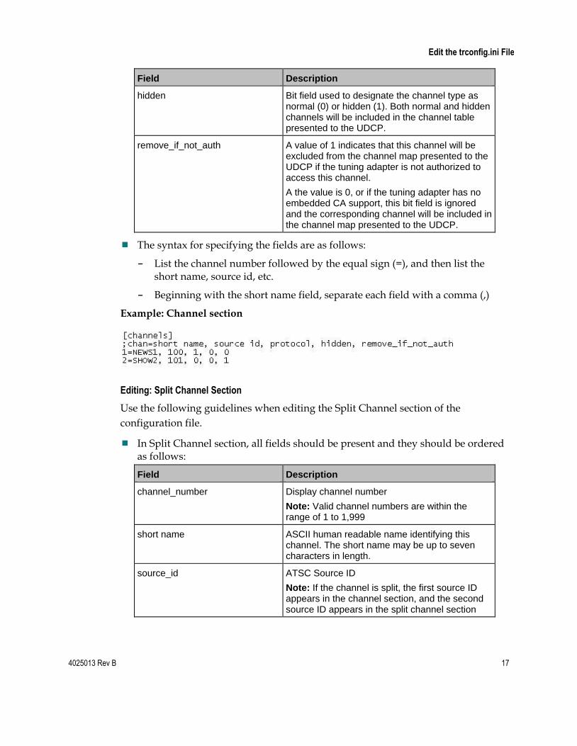
hidden Bit field used to designate the channel type as normal (0) or hidden (1). Both normal and hidden channels will be included in the channel table presented to the UDCP.
remove_if_not_auth A value of 1 indicates that this channel will be excluded from the channel map presented to the UDCP if the tuning adapter is not authorized to access this channel.
A the value is 0, or if the tuning adapter has no embedded CA support, this bit field is ignored and the corresponding channel will be included in the channel map presented to the UDCP.
The syntax for specifying the fields are as follows:
- List the channel number followed by the equal sign (=), and then list the short name, source id, etc.
- Beginning with the short name field, separate each field with a comma (,)
Example: Channel section
Editing: Split Channel Section
Use the following guidelines when editing the Split Channel section of the
configuration file.
In Split Channel section, all fields should be present and they should be ordered as follows:
Field Description
channel_number Display channel number
Note: Valid channel numbers are within the range of 1 to 1,999
short name ASCII human readable name identifying this channel. The short name may be up to seven characters in length.
source_id ATSC Source ID
Note: If the channel is split, the first source ID appears in the channel section, and the second source ID appears in the split channel section
18 4025013 Rev B
Edit the trconfig.ini File
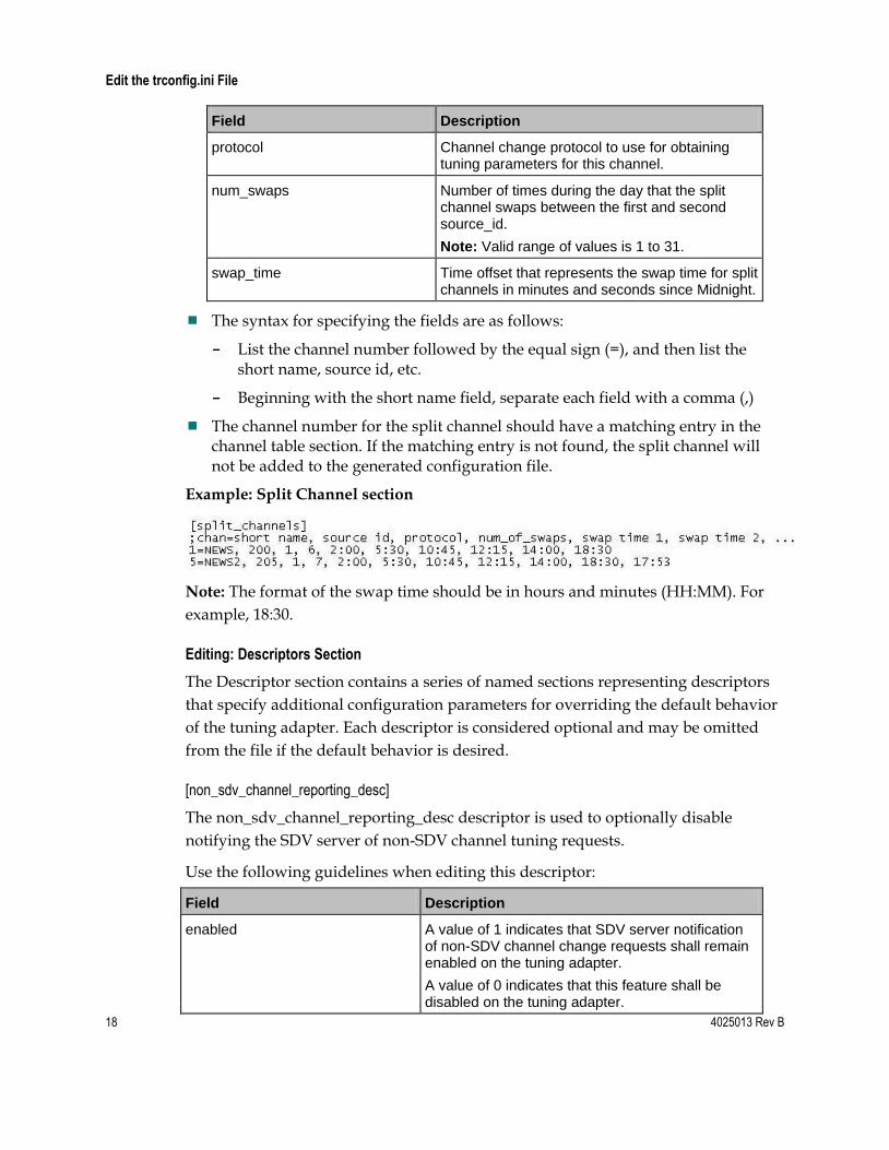
Field Description
protocol Channel change protocol to use for obtaining tuning parameters for this channel.
num_swaps Number of times during the day that the split channel swaps between the first and second source_id.
Note: Valid range of values is 1 to 31.
swap_time Time offset that represents the swap time for split channels in minutes and seconds since Midnight.
The syntax for specifying the fields are as follows:
- List the channel number followed by the equal sign (=), and then list the short name, source id, etc.
- Beginning with the short name field, separate each field with a comma (,)
The channel number for the split channel should have a matching entry in the channel table section. If the matching entry is not found, the split channel will not be added to the generated configuration file.
Example: Split Channel section
Note: The format of the swap time should be in hours and minutes (HH:MM). For
example, 18:30.
Editing: Descriptors Section
The Descriptor section contains a series of named sections representing descriptors
that specify additional configuration parameters for overriding the default behavior
of the tuning adapter. Each descriptor is considered optional and may be omitted
from the file if the default behavior is desired.
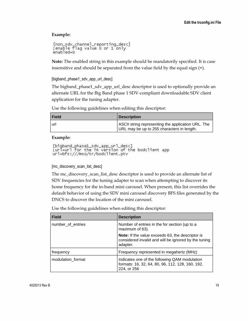
[non_sdv_channel_reporting_desc]
The non_sdv_channel_reporting_desc descriptor is used to optionally disable
notifying the SDV server of non-SDV channel tuning requests.
Use the following guidelines when editing this descriptor:
Field Description
enabled A value of 1 indicates that SDV server notification of non-SDV channel change requests shall remain enabled on the tuning adapter.
A value of 0 indicates that this feature shall be disabled on the tuning adapter.
4025013 Rev B 19
Edit the trconfig.ini File
Example:
Note: The enabled string in this example should be mandatorily specified. It is case
insensitive and should be separated from the value field by the equal sign (=).
[bigband_phase1_sdv_app_url_desc]
The bigband_phase1_sdv_app_url_desc descriptor is used to optionally provide an
alternate URL for the Big Band phase 1 SDV-compliant downloadable SDV client
application for the tuning adapter.
Use the following guidelines when editing this descriptor:
Field Description
url ASCII string representing the application URL. The URL may be up to 255 characters in length.
Example:
[mc_discovery_scan_list_desc]
The mc_discovery_scan_list_desc descriptor is used to provide an alternate list of
SDV frequencies for the tuning adapter to scan when attempting to discover its
home frequency for the in-band mini carousel. When present, this list overrides the
default behavior of using the SDV mini carousel discovery BFS files generated by the
DNCS to discover the location of the mini carousel.
Use the following guidelines when editing this descriptor:
Field Description
number_of_entries Number of entries in the for section (up to a maximum of 63).
Note: If the value exceeds 63, the descriptor is considered invalid and will be ignored by the tuning adapter.
frequency Frequency represented in megahertz (MHz)
modulation_format Indicates one of the following QAM modulation formats: 16, 32, 64, 80, 96, 112, 128, 160, 192, 224, or 256
20 4025013 Rev B
Edit the trconfig.ini File
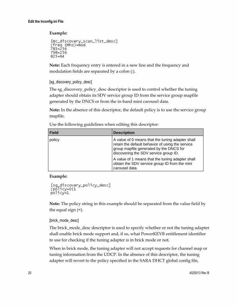
Example:
Note: Each frequency entry is entered in a new line and the frequency and
modulation fields are separated by a colon (:).
[sg_discovery_policy_desc]
The sg_discovery_policy_desc descriptor is used to control whether the tuning
adapter should obtain its SDV service group ID from the service group mapfile
generated by the DNCS or from the in-band mini carousel data.
Note: In the absence of this descriptor, the default policy is to use the service group
mapfile.
Use the following guidelines when editing this descriptor:
Field Description
policy A value of 0 means that the tuning adapter shall retain the default behavior of using the service group mapfile generated by the DNCS for discovering the SDV service group ID.
A value of 1 means that the tuning adapter shall obtain the SDV service group ID from the mini carousel data.
Example:
Note: The policy string in this example should be separated from the value field by
the equal sign (=).
[brick_mode_desc]
The brick_mode_desc descriptor is used to specify whether or not the tuning adapter
shall enable brick mode support and, if so, what PowerKEY® entitlement identifier
to use for checking if the tuning adapter is in brick mode or not.
When in brick mode, the tuning adapter will not accept requests for channel map or
tuning information from the UDCP. In the absence of this descriptor, the tuning
adapter will revert to the policy specified in the SARA DHCT global config file,

4025013 Rev B 21
Edit the trconfig.ini File
generated by the SARA Application Server. If that file is not present, then the tuning
adapter will not enable brick mode support.
22 4025013 Rev B
Edit the trconfig.ini File
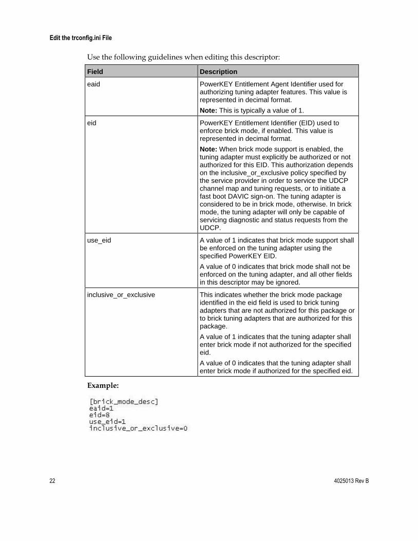
Use the following guidelines when editing this descriptor:
Field Description
eaid PowerKEY Entitlement Agent Identifier used for authorizing tuning adapter features. This value is represented in decimal format.
Note: This is typically a value of 1.
eid PowerKEY Entitlement Identifier (EID) used to enforce brick mode, if enabled. This value is represented in decimal format.
Note: When brick mode support is enabled, the tuning adapter must explicitly be authorized or not authorized for this EID. This authorization depends on the inclusive_or_exclusive policy specified by the service provider in order to service the UDCP channel map and tuning requests, or to initiate a fast boot DAVIC sign-on. The tuning adapter is considered to be in brick mode, otherwise. In brick mode, the tuning adapter will only be capable of servicing diagnostic and status requests from the UDCP.
use_eid A value of 1 indicates that brick mode support shall be enforced on the tuning adapter using the specified PowerKEY EID.
A value of 0 indicates that brick mode shall not be enforced on the tuning adapter, and all other fields in this descriptor may be ignored.
inclusive_or_exclusive This indicates whether the brick mode package identified in the eid field is used to brick tuning adapters that are not authorized for this package or to brick tuning adapters that are authorized for this package.
A value of 1 indicates that the tuning adapter shall enter brick mode if not authorized for the specified eid.
A value of 0 indicates that the tuning adapter shall enter brick mode if authorized for the specified eid.
Example:

For Information
If You Have Questions
If you have technical questions, call Cisco Services for assistance. Follow the menu
options to speak with a service engineer.
Cisco Systems, Inc. 5030 Sugarloaf Parkway, Box 465447 Lawrenceville, GA 30042
678 277-1120 800 722-2009
www.cisco.com
Cisco and the Cisco logo are trademarks or registered trademarks of Cisco and/or its affiliates in the U.S. and other countries. A listing of Cisco's trademarks can be found at www.cisco.com/go/trademarks. CableCARD is a trademark of Cable Television Laboratories, Inc. Other third party trademarks mentioned are the property of their respective owners. The use of the word partner does not imply a partnership relationship between Cisco and any other company. (1009R) Product and service availability are subject to change without notice.
© 2010, 2012 Cisco and/or its affiliates. All rights reserved.
May 2012 Part Number 4025013 Rev B