Embed Size (px)
Citation preview
Downhole GRAvity Slip Separator
Olav Selle jr.B̊ard Tobiassen
Cecilie GjengedalKornelius Drange Hole
H̊avard Stranden
NTNUNorwegian University of Science and Technology
May 10, 2005
Abstract
The Downhole GRAvity Slip Separator (DGRASS)is a new system for downhole separation. It is basedon gravitational separation of oil and water. Thispaper presents the functionality of DGRASS, anda production analysis of DGRASS using data fromthree mature wells at the Gullfaks A oil field. Fi-nally, it discusses how well completion can be donewith DGRASS.
1 Introduction to DGRASS
DGRASS is based on gravitational separation of oilfrom water. What makes it so interesting is the factthat it is the production pipe itself.
A special challenge for downhole separation is theseparator diameter restriction. While separatorlengths of tens of meters are easy to implement,their diameter is usually restricted to below 0.3m.A challenge is then to develop a design where thesmall diameter may be compensated by extendedlength. The piping in a well consists of sectionsthat are 10m long. Three of these sections are puttogether, forming a total length of 30m. DGRASSmay consist of as many of these 30m sections as de-sired. Thus, DGRASS solves the extended lengthchallenge of downhole separation [8].
Installing DGRASS may have several positive ef-fects:
• Higher production rate due to lower well pres-sure increases the flow towards the well
• Increases the reservoir lifetime, as it can pro-duce with economical benefits on high watercuts
• No gas in the water phase makes it energy sav-ing when it pumpes the major water phase upto lower pressure
• Faster separation on the platform
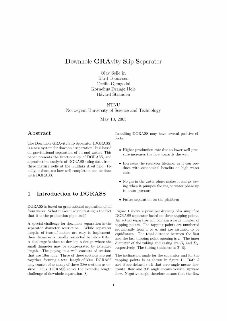
Figure 1 shows a principal drawing of a simplifiedDGRASS separator based on three tapping points.An actual separator will contain a large number oftapping points. The tapping points are numberedsequentially from 1 to n, and are assumed to beequidistant. The total distance between the firstand the last tapping point opening is L. The innerdiameter of the tubing and casing are Dt and Da,respectively. The tubing thickness is T [9].
The inclination angle for the separator and for thetapping points is as shown in figure 1. Both θand β are defined such that zero angle means hor-izontal flow and 90◦ angle means vertical upwardflow. Negative angle therefore means that the flow
1
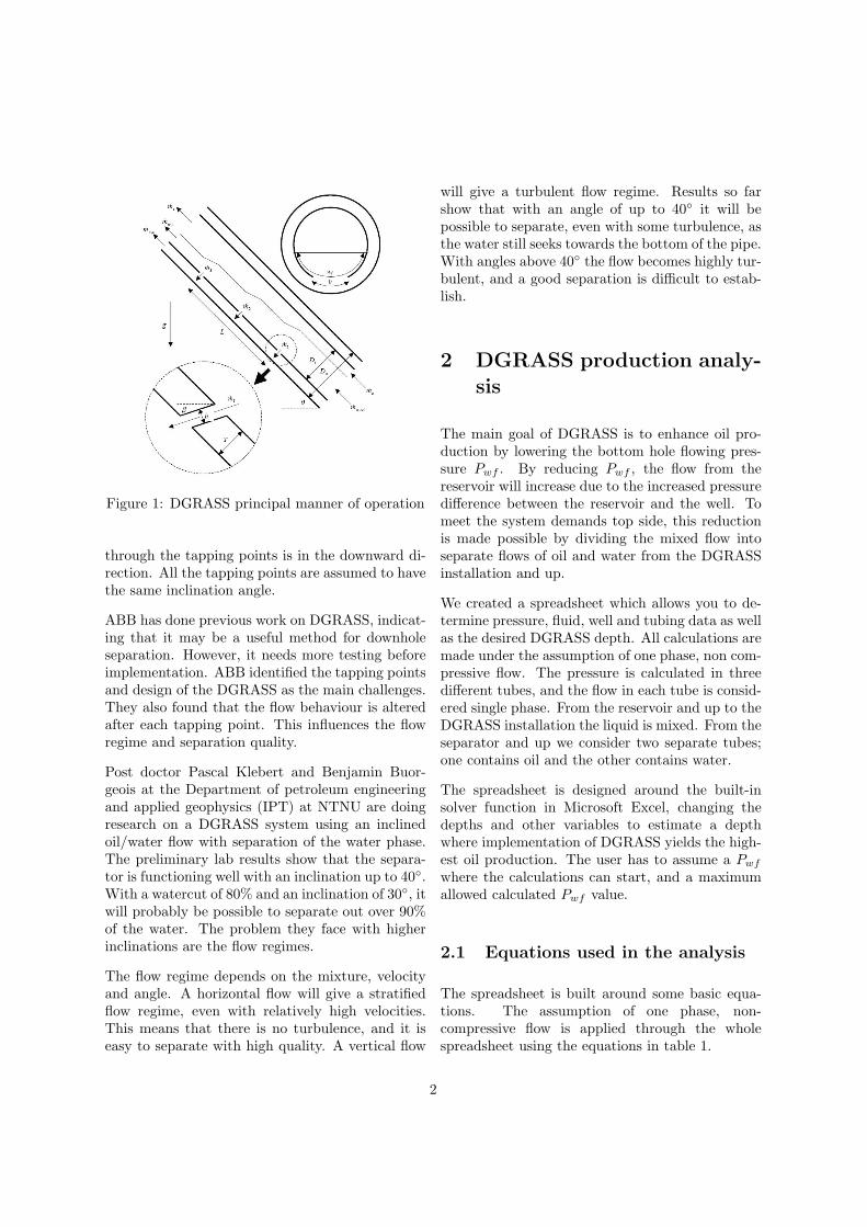
Figure 1: DGRASS principal manner of operation
through the tapping points is in the downward di-rection. All the tapping points are assumed to havethe same inclination angle.
ABB has done previous work on DGRASS, indicat-ing that it may be a useful method for downholeseparation. However, it needs more testing beforeimplementation. ABB identified the tapping pointsand design of the DGRASS as the main challenges.They also found that the flow behaviour is alteredafter each tapping point. This influences the flowregime and separation quality.
Post doctor Pascal Klebert and Benjamin Buor-geois at the Department of petroleum engineeringand applied geophysics (IPT) at NTNU are doingresearch on a DGRASS system using an inclinedoil/water flow with separation of the water phase.The preliminary lab results show that the separa-tor is functioning well with an inclination up to 40◦.With a watercut of 80% and an inclination of 30◦, itwill probably be possible to separate out over 90%of the water. The problem they face with higherinclinations are the flow regimes.
The flow regime depends on the mixture, velocityand angle. A horizontal flow will give a stratifiedflow regime, even with relatively high velocities.This means that there is no turbulence, and it iseasy to separate with high quality. A vertical flow
will give a turbulent flow regime. Results so farshow that with an angle of up to 40◦ it will bepossible to separate, even with some turbulence, asthe water still seeks towards the bottom of the pipe.With angles above 40◦ the flow becomes highly tur-bulent, and a good separation is difficult to estab-lish.
2 DGRASS production analy-sis
The main goal of DGRASS is to enhance oil pro-duction by lowering the bottom hole flowing pres-sure Pwf . By reducing Pwf , the flow from thereservoir will increase due to the increased pressuredifference between the reservoir and the well. Tomeet the system demands top side, this reductionis made possible by dividing the mixed flow intoseparate flows of oil and water from the DGRASSinstallation and up.
We created a spreadsheet which allows you to de-termine pressure, fluid, well and tubing data as wellas the desired DGRASS depth. All calculations aremade under the assumption of one phase, non com-pressive flow. The pressure is calculated in threedifferent tubes, and the flow in each tube is consid-ered single phase. From the reservoir and up to theDGRASS installation the liquid is mixed. From theseparator and up we consider two separate tubes;one contains oil and the other contains water.
The spreadsheet is designed around the built-insolver function in Microsoft Excel, changing thedepths and other variables to estimate a depthwhere implementation of DGRASS yields the high-est oil production. The user has to assume a Pwf
where the calculations can start, and a maximumallowed calculated Pwf value.
2.1 Equations used in the analysis
The spreadsheet is built around some basic equa-tions. The assumption of one phase, non-compressive flow is applied through the wholespreadsheet using the equations in table 1.
2
Name EquationProductivity index [3] Q = J ∗ (Pr − Pwf )
Reynolds number [6] Re = ρDuµ
Haalands equation [6] fm = 1(−1.8log( 6.9
Re+( e
3.7D
)1.11)2
Pressure loss due tofriction [3] ∆Pf = 1
2 fm ∗ ρ ∗ u2 ∗ hD
Pressure loss due tohydrostatical head [3] ∆Ph = ρgh
Table 1: Production analysis equations
The pressure at the DGRASS installation is cal-culated separately for each tube as shown in table2. Herein, the different pressure losses are calcu-lated with their respective material properties, truevertical depth (TVD), measured depth (MD) andpercentage of water. The different depths are de-scribed in figure 2.
Tube EquationTube A Pdgrass = Pwf − (∆Pf + ∆Ph)Tube B Pgrass = Psoil + (∆Pf + ∆Ph)Tube C Pgrass = Pswater + (∆Pf + ∆Ph)
Reference tube Pwf = Psep + (∆Pf + ∆Ph)
Table 2: Equations for the different tubes
Figure 2: Production analysis model
2.2 Implementation depth in Gull-faks wells
By applying real well data from Statoil as input,an analysis with regards to placement depth versus
production results has been performed. A selectionof the best range of depth in which to implementDGRASS is chosen for each well. The range ofdepth is then calculated in the production analy-sis spreadsheet. The main production data for thethree wells is presented in table 3. During all evalu-ations casing diameter, giving the equivalent annu-lus diameter, has been assumed equal throughoutthe whole well.
Well Productivity index Reservoir pressure Water cut
A-8R2 0.00038 m3s∗bar
274.96bar 80.5%
A-16A 0.00046 m3s∗bar
299.92bar 75.9%
A-23 0.00417 m3s∗bar
299.92bar 85.5%
Table 3: Main production data for the Gullfaks Awells
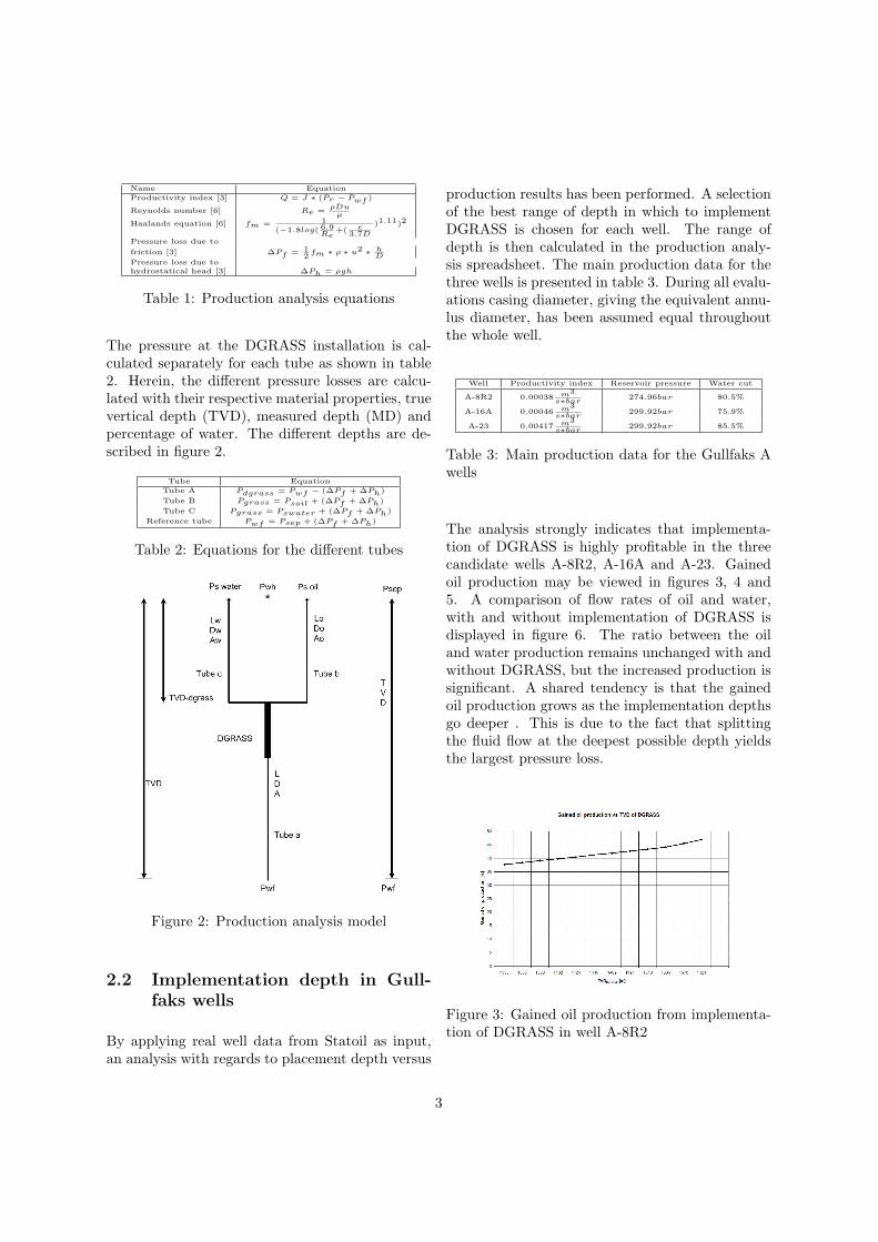
The analysis strongly indicates that implementa-tion of DGRASS is highly profitable in the threecandidate wells A-8R2, A-16A and A-23. Gainedoil production may be viewed in figures 3, 4 and5. A comparison of flow rates of oil and water,with and without implementation of DGRASS isdisplayed in figure 6. The ratio between the oiland water production remains unchanged with andwithout DGRASS, but the increased production issignificant. A shared tendency is that the gainedoil production grows as the implementation depthsgo deeper . This is due to the fact that splittingthe fluid flow at the deepest possible depth yieldsthe largest pressure loss.
Figure 3: Gained oil production from implementa-tion of DGRASS in well A-8R2
3
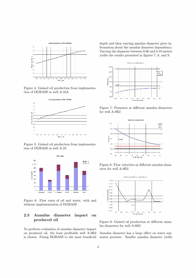
Figure 4: Gained oil production from implementa-tion of DGRASS in well A-16A
Figure 5: Gained oil production from implementa-tion of DGRASS in well A-23
Figure 6: Flow rates of oil and water, with andwithout implementation of DGRASS
2.3 Annulus diameter impact onproduced oil
To perform evaluation of annulus diameter impacton produced oil, the least profitable well A-8R2is chosen. Fixing DGRASS to the most beneficial
depth and then varying annulus diameter gives in-formation about the annulus diameter dependency.Varying the diameter between 0.06 and 0.10 metersyields the results presented in figures 7, 8, and 9.
Figure 7: Pressures at different annulus diametersfor well A-8R2
Figure 8: Flow velocities at different annulus diam-eters for well A-8R2
Figure 9: Gained oil production at different annu-lus diameters for well A-8R2
Annulus diameter has a large effect on water sep-arator pressure. Smaller annulus diameter yields
4
lower possible pressure of water separator. In fact,if the diameter is too small, vacuum is created.However, annulus diameter has no significant im-pact on gained oil production.
2.4 Water cut impact on producedoil
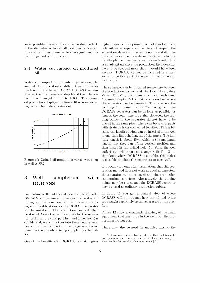
Water cut impact is evaluated by viewing theamount of produced oil at different water cuts forthe least profitable well, A-8R2. DGRASS remainsfixed to the most beneficial depth and then the wa-ter cut is changed from 0 to 100%. The gainedoil production displayed in figure 10 is as expectedhighest at the highest water cut.
Figure 10: Gained oil production versus water cutin well A-8R2
3 Well completion withDGRASS
For mature wells, additional new completion withDGRASS will be limited. The existing productiontubing will be taken out and a production tub-ing with modifications for the DGRASS separatorwill be installed. The production flow will thenbe started. Since the technical data for the separa-tor (technical drawing, part list, and dimensions) isconfidential, we will not go into these details here.We will do the completion in more general terms,based on the already existing completion schemat-ics.
One of the benefits with DGRASS is that it gives
higher capacity than present technologies for down-hole oil/water separation, while still keeping theseparation device simple and easy to install. Theinstallation can be done during workover, which isusually planned one year ahead for each well. Thisis an advantage since the production then does nothave to be stopped more than it would have beenanyway. DGRASS cannot be installed in a hori-zontal or vertical part of the well; it has to have aninclination.
The separator can be installed somewhere betweenthe production packer and the DownHole SafetyValve (DHSV)1, but there is a lower authorizedMeasured Depth (MD) that is a bound on wherethe separator can be inserted. This is where thecoupling 5in casing to the 7in casing is. TheDGRASS separator can be as long as possible, aslong as the conditions are right. However, the tap-ping points in the separator do not have to beplaced in the same pipe. There can be several partswith draining holes connected together. This is be-cause the length of what can be inserted in the wellin one time limit the lengths of the parts. The lim-iting length is about 45m, which is the maximumlength that they can lift in vertical position andthen insert in the drilled hole [5]. Since the welltrajectory inclination can change with 1◦ − 2◦ inthe places where DGRASS is suitable, this makesit possible to adapt the separators to each well.
If it would turn out, after installation, that this sep-aration method does not work as good as expected,the separator can be removed and the productioncan continue as before. Alternatively, the tappingpoints may be closed and the DGRASS separatormay be used as ordinary production tubing.
In figure 11 you get a general view of whereDGRASS will be put and how the oil and waterare brought separately to the separators at the plat-form.
Figure 12 show a schematic drawing of the mainequipment that has to be in the well, but the pro-portions are not real.
There may also be need for modifications on the
1A downhole safety valve is a device that isolates well-bore pressure and fluids in the event of an emergency orcatastrophic failure of surface equipment [7].
5
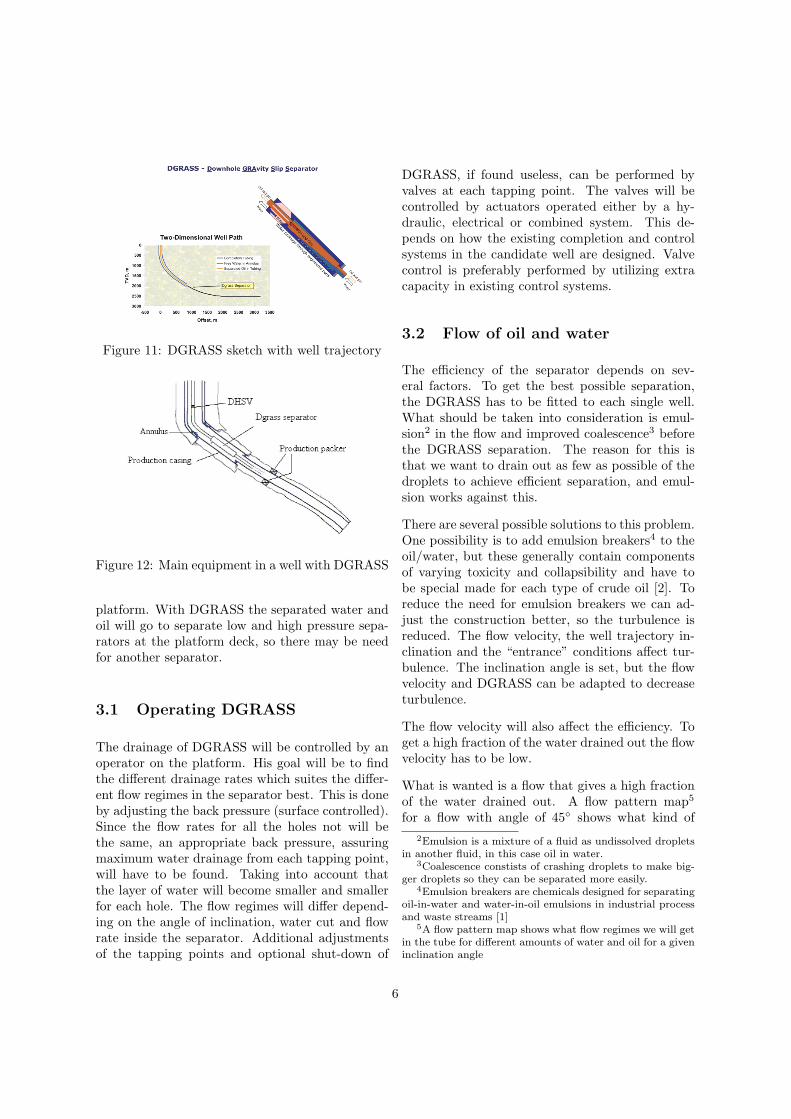
Figure 11: DGRASS sketch with well trajectory
Figure 12: Main equipment in a well with DGRASS
platform. With DGRASS the separated water andoil will go to separate low and high pressure sepa-rators at the platform deck, so there may be needfor another separator.
3.1 Operating DGRASS
The drainage of DGRASS will be controlled by anoperator on the platform. His goal will be to findthe different drainage rates which suites the differ-ent flow regimes in the separator best. This is doneby adjusting the back pressure (surface controlled).Since the flow rates for all the holes not will bethe same, an appropriate back pressure, assuringmaximum water drainage from each tapping point,will have to be found. Taking into account thatthe layer of water will become smaller and smallerfor each hole. The flow regimes will differ depend-ing on the angle of inclination, water cut and flowrate inside the separator. Additional adjustmentsof the tapping points and optional shut-down of
DGRASS, if found useless, can be performed byvalves at each tapping point. The valves will becontrolled by actuators operated either by a hy-draulic, electrical or combined system. This de-pends on how the existing completion and controlsystems in the candidate well are designed. Valvecontrol is preferably performed by utilizing extracapacity in existing control systems.
3.2 Flow of oil and water
The efficiency of the separator depends on sev-eral factors. To get the best possible separation,the DGRASS has to be fitted to each single well.What should be taken into consideration is emul-sion2 in the flow and improved coalescence3 beforethe DGRASS separation. The reason for this isthat we want to drain out as few as possible of thedroplets to achieve efficient separation, and emul-sion works against this.
There are several possible solutions to this problem.One possibility is to add emulsion breakers4 to theoil/water, but these generally contain componentsof varying toxicity and collapsibility and have tobe special made for each type of crude oil [2]. Toreduce the need for emulsion breakers we can ad-just the construction better, so the turbulence isreduced. The flow velocity, the well trajectory in-clination and the “entrance” conditions affect tur-bulence. The inclination angle is set, but the flowvelocity and DGRASS can be adapted to decreaseturbulence.
The flow velocity will also affect the efficiency. Toget a high fraction of the water drained out the flowvelocity has to be low.
What is wanted is a flow that gives a high fractionof the water drained out. A flow pattern map5
for a flow with angle of 45◦ shows what kind of2Emulsion is a mixture of a fluid as undissolved droplets
in another fluid, in this case oil in water.3Coalescence constists of crashing droplets to make big-
ger droplets so they can be separated more easily.4Emulsion breakers are chemicals designed for separating
oil-in-water and water-in-oil emulsions in industrial processand waste streams [1]
5A flow pattern map shows what flow regimes we will getin the tube for different amounts of water and oil for a giveninclination angle
6
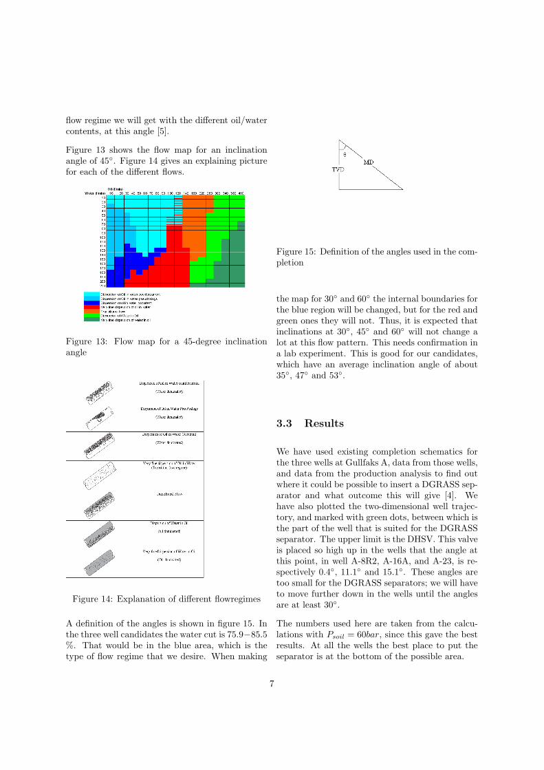
flow regime we will get with the different oil/watercontents, at this angle [5].
Figure 13 shows the flow map for an inclinationangle of 45◦. Figure 14 gives an explaining picturefor each of the different flows.
Figure 13: Flow map for a 45-degree inclinationangle
Figure 14: Explanation of different flowregimes
A definition of the angles is shown in figure 15. Inthe three well candidates the water cut is 75.9−85.5%. That would be in the blue area, which is thetype of flow regime that we desire. When making
Figure 15: Definition of the angles used in the com-pletion
the map for 30◦ and 60◦ the internal boundaries forthe blue region will be changed, but for the red andgreen ones they will not. Thus, it is expected thatinclinations at 30◦, 45◦ and 60◦ will not change alot at this flow pattern. This needs confirmation ina lab experiment. This is good for our candidates,which have an average inclination angle of about35◦, 47◦ and 53◦.
3.3 Results
We have used existing completion schematics forthe three wells at Gullfaks A, data from those wells,and data from the production analysis to find outwhere it could be possible to insert a DGRASS sep-arator and what outcome this will give [4]. Wehave also plotted the two-dimensional well trajec-tory, and marked with green dots, between which isthe part of the well that is suited for the DGRASSseparator. The upper limit is the DHSV. This valveis placed so high up in the wells that the angle atthis point, in well A-8R2, A-16A, and A-23, is re-spectively 0.4◦, 11.1◦ and 15.1◦. These angles aretoo small for the DGRASS separators; we will haveto move further down in the wells until the anglesare at least 30◦.
The numbers used here are taken from the calcu-lations with Psoil = 60bar, since this gave the bestresults. At all the wells the best place to put theseparator is at the bottom of the possible area.
7
3.3.1 Gullfaks A-8R2
This well is the shortest in MD (Measured Depth)and TVD (True Vertical Depth). The lower autho-rized MD is 1718.90m, and the TVD is 1621.03m.
At the relevant part of the well we have:
• Inclination angle: 31.6◦ − 36.7◦, only a smallpart has 31◦ − 34◦ before mainly about 35◦ −36◦
• TVD: From about 1335m to about 1621m
• Length: About 1718m − 1367m = 351m, butfor the part where the inclination angle is moststable the length is 1718m− 1421m = 297m
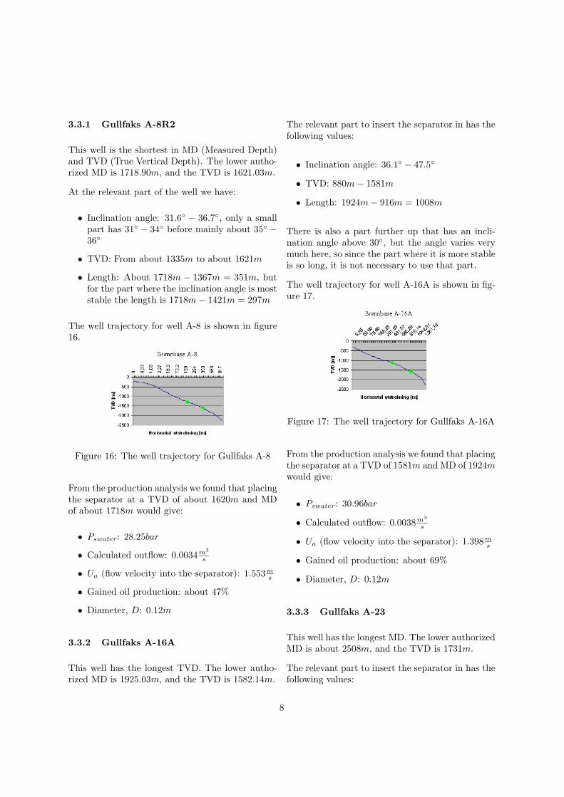
The well trajectory for well A-8 is shown in figure16.
Figure 16: The well trajectory for Gullfaks A-8
From the production analysis we found that placingthe separator at a TVD of about 1620m and MDof about 1718m would give:
• Pswater: 28.25bar
• Calculated outflow: 0.0034m3
s
• Ua (flow velocity into the separator): 1.553ms
• Gained oil production: about 47%
• Diameter, D: 0.12m
3.3.2 Gullfaks A-16A
This well has the longest TVD. The lower autho-rized MD is 1925.03m, and the TVD is 1582.14m.
The relevant part to insert the separator in has thefollowing values:
• Inclination angle: 36.1◦ − 47.5◦
• TVD: 880m− 1581m
• Length: 1924m− 916m = 1008m
There is also a part further up that has an incli-nation angle above 30◦, but the angle varies verymuch here, so since the part where it is more stableis so long, it is not necessary to use that part.
The well trajectory for well A-16A is shown in fig-ure 17.
Figure 17: The well trajectory for Gullfaks A-16A
From the production analysis we found that placingthe separator at a TVD of 1581m and MD of 1924mwould give:
• Pswater: 30.96bar
• Calculated outflow: 0.0038m3
s
• Ua (flow velocity into the separator): 1.398ms
• Gained oil production: about 69%
• Diameter, D: 0.12m
3.3.3 Gullfaks A-23
This well has the longest MD. The lower authorizedMD is about 2508m, and the TVD is 1731m.
The relevant part to insert the separator in has thefollowing values:
8
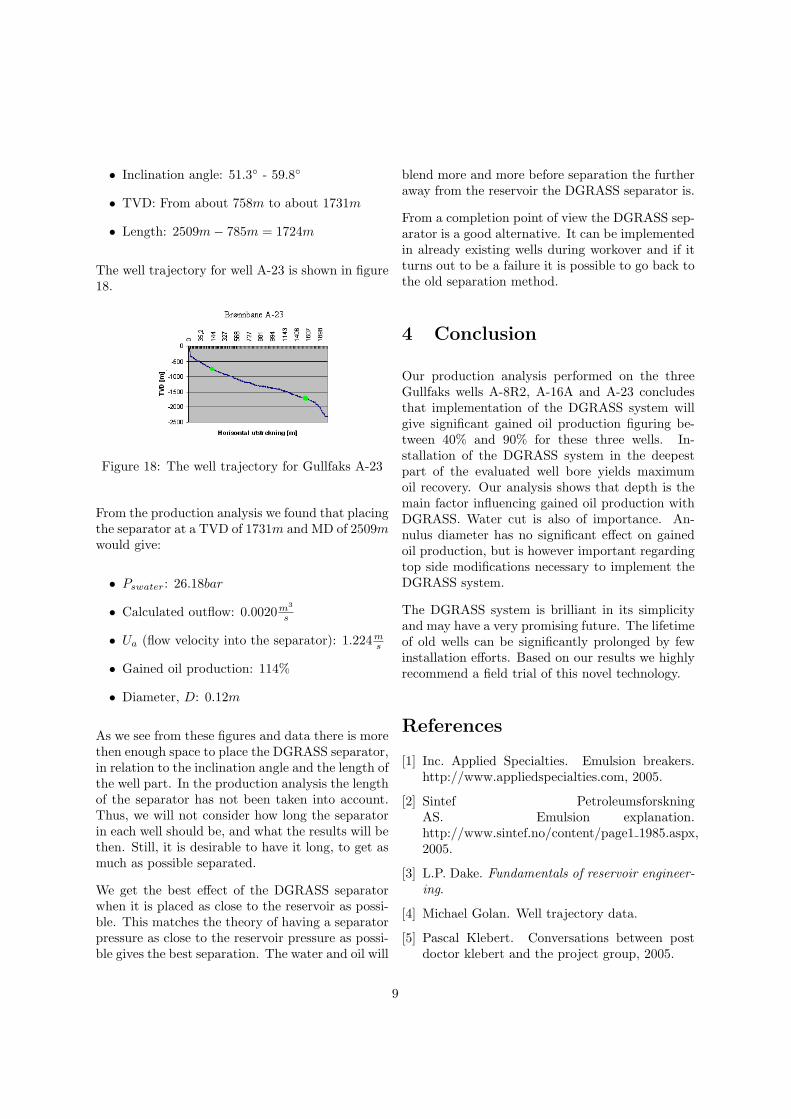
• Inclination angle: 51.3◦ - 59.8◦
• TVD: From about 758m to about 1731m
• Length: 2509m− 785m = 1724m
The well trajectory for well A-23 is shown in figure18.
Figure 18: The well trajectory for Gullfaks A-23
From the production analysis we found that placingthe separator at a TVD of 1731m and MD of 2509mwould give:
• Pswater: 26.18bar
• Calculated outflow: 0.0020m3
s
• Ua (flow velocity into the separator): 1.224ms
• Gained oil production: 114%
• Diameter, D: 0.12m
As we see from these figures and data there is morethen enough space to place the DGRASS separator,in relation to the inclination angle and the length ofthe well part. In the production analysis the lengthof the separator has not been taken into account.Thus, we will not consider how long the separatorin each well should be, and what the results will bethen. Still, it is desirable to have it long, to get asmuch as possible separated.
We get the best effect of the DGRASS separatorwhen it is placed as close to the reservoir as possi-ble. This matches the theory of having a separatorpressure as close to the reservoir pressure as possi-ble gives the best separation. The water and oil will
blend more and more before separation the furtheraway from the reservoir the DGRASS separator is.
From a completion point of view the DGRASS sep-arator is a good alternative. It can be implementedin already existing wells during workover and if itturns out to be a failure it is possible to go back tothe old separation method.
4 Conclusion
Our production analysis performed on the threeGullfaks wells A-8R2, A-16A and A-23 concludesthat implementation of the DGRASS system willgive significant gained oil production figuring be-tween 40% and 90% for these three wells. In-stallation of the DGRASS system in the deepestpart of the evaluated well bore yields maximumoil recovery. Our analysis shows that depth is themain factor influencing gained oil production withDGRASS. Water cut is also of importance. An-nulus diameter has no significant effect on gainedoil production, but is however important regardingtop side modifications necessary to implement theDGRASS system.
The DGRASS system is brilliant in its simplicityand may have a very promising future. The lifetimeof old wells can be significantly prolonged by fewinstallation efforts. Based on our results we highlyrecommend a field trial of this novel technology.
References
[1] Inc. Applied Specialties. Emulsion breakers.http://www.appliedspecialties.com, 2005.
[2] Sintef PetroleumsforskningAS. Emulsion explanation.http://www.sintef.no/content/page1 1985.aspx,2005.
[3] L.P. Dake. Fundamentals of reservoir engineer-ing.
[4] Michael Golan. Well trajectory data.
[5] Pascal Klebert. Conversations between postdoctor klebert and the project group, 2005.
9
[6] Okiishi Munson, Young. Fundamentals of fluiddynamics.
[7] Schlumberger. Schlumberger oilfield glossary.http://www.glossary.oilfield.slb.com.
[8] ABB Corporate Research Svein H̊aheim.Oil/water slip in inclined pipes and applicationto downhole separation. ABB research.
[9] Ivar Balk Svein H̊aheim, ABB Offshore Systemsand Rune Killie. Experimental study of inclinedoil/water flow with separation. ABB research.
10