Embed Size (px)
Citation preview
U C IP E L
UCI Power Electronics Lab
1
Keyue Smedley, Ph.D.
Dept. of Electrical Eng. and Computer Science
University of California,
Irvine, CA 92697, USA
Down the Road to Hydrogen Power
U C IP E L
UCI Power Electronics Lab
2
Abstract
Energy is a vital force that powers our homes, schools, businesses,transportation, manufacturing, agriculture, service, military, andspace-exploration. Currently, about 99% of the energy fortransportation and 70% of the energy for power generation are fromfossil fuel. Our dependence on fossil fuel has resulted in many socialproblems such as energy shortages, environmental impact, andeconomic dependence. On the other hand, a tantalizing picture of ahydrogen economy appeals to the news media everyday where blueskies without pollution and a booming economy with secure powerare the expected results. How can we get there? In this presentation,I will talk about fuel cell technology, power electronics advancement,as well as research and development in the US towards hydrogenpower generation.
U C IP E L
UCI Power Electronics Lab
3
Table of Contents
I. Introduction
II. Fuel Cell Technology
III. Hydrogen Technology
IV. Fuel Cell Applications
V. Power Electronics for Hydrogen Power
U C IP E L
UCI Power Electronics Lab
4
I. Introduction
U C IP E L
UCI Power Electronics Lab
5
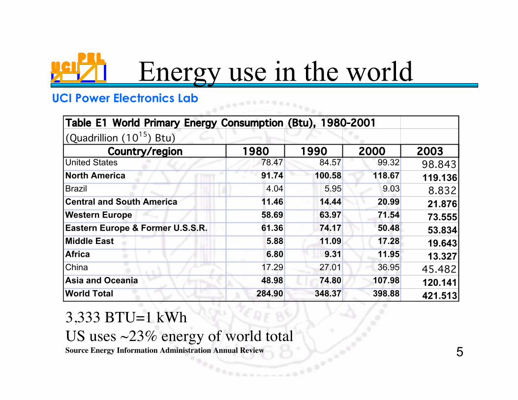
Table E1 World Primary Energy Consumption (Btu), 1980-2001(Quadrillion (1015) Btu)
Country/region 1980 1990 2000 2003United States 78.47 84.57 99.32 98.843North America 91.74 100.58 118.67 119.136Brazil 4.04 5.95 9.03 8.832Central and South America 11.46 14.44 20.99 21.876Western Europe 58.69 63.97 71.54 73.555Eastern Europe & Former U.S.S.R. 61.36 74.17 50.48 53.834Middle East 5.88 11.09 17.28 19.643Africa 6.80 9.31 11.95 13.327China 17.29 27.01 36.95 45.482Asia and Oceania 48.98 74.80 107.98 120.141World Total 284.90 348.37 398.88 421.513
3,333 BTU=1 kWhUS uses ~23% energy of world totalSource Energy Information Administration Annual Review
Energy use in the world
U C IP E L
UCI Power Electronics Lab
6
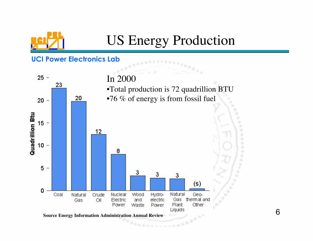
US Energy Production
In 2000•Total production is 72 quadrillion BTU•76 % of energy is from fossil fuel
Source Energy Information Administration Annual Review
U C IP E L
UCI Power Electronics Lab
7
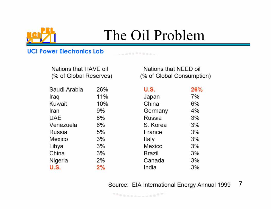
The Oil Problem
U C IP E L
UCI Power Electronics Lab
8
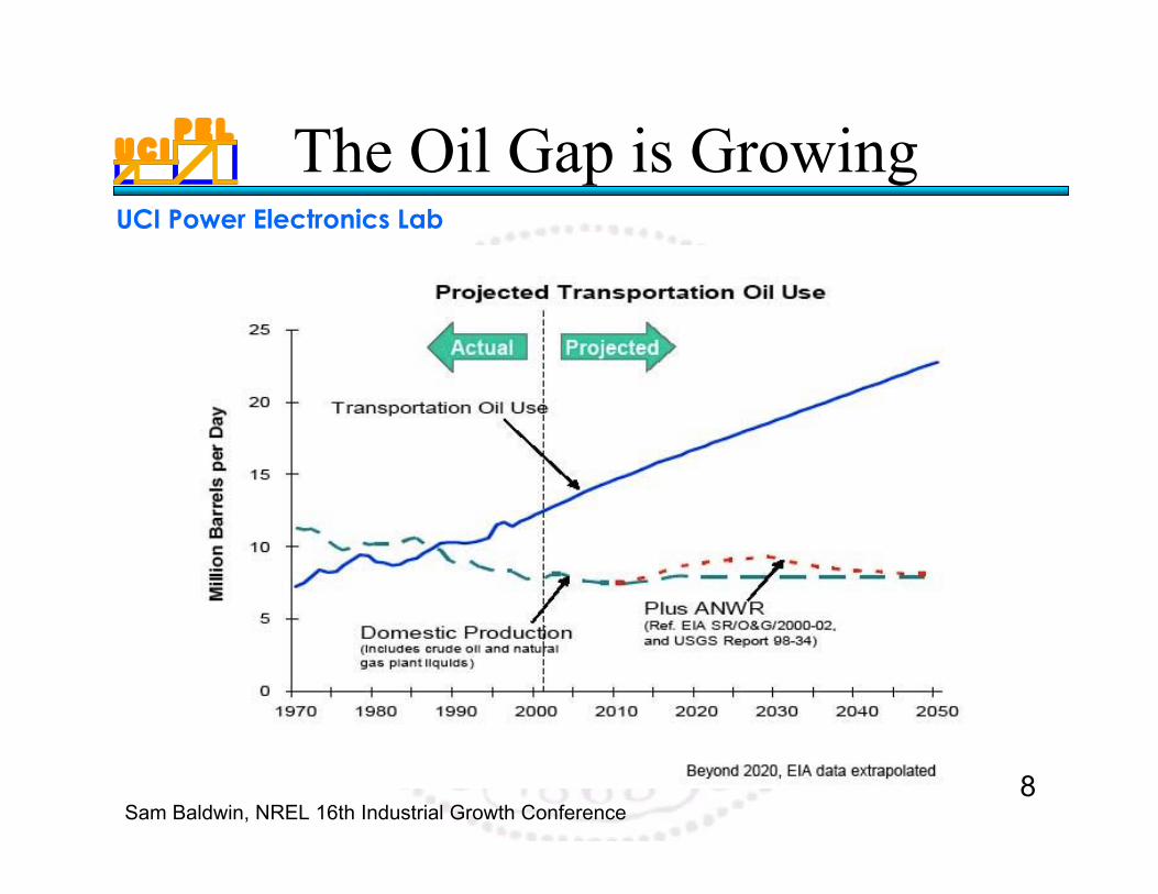
The Oil Gap is Growing
Sam Baldwin, NREL 16th Industrial Growth Conference
U C IP E L
UCI Power Electronics Lab
9
Environmental Impact
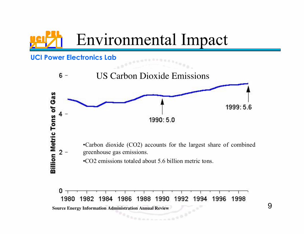
US Carbon Dioxide Emissions
•Carbon dioxide (CO2) accounts for the largest share of combinedgreenhouse gas emissions.
•CO2 emissions totaled about 5.6 billion metric tons.
Source Energy Information Administration Annual Review
U C IP E L
UCI Power Electronics Lab
10
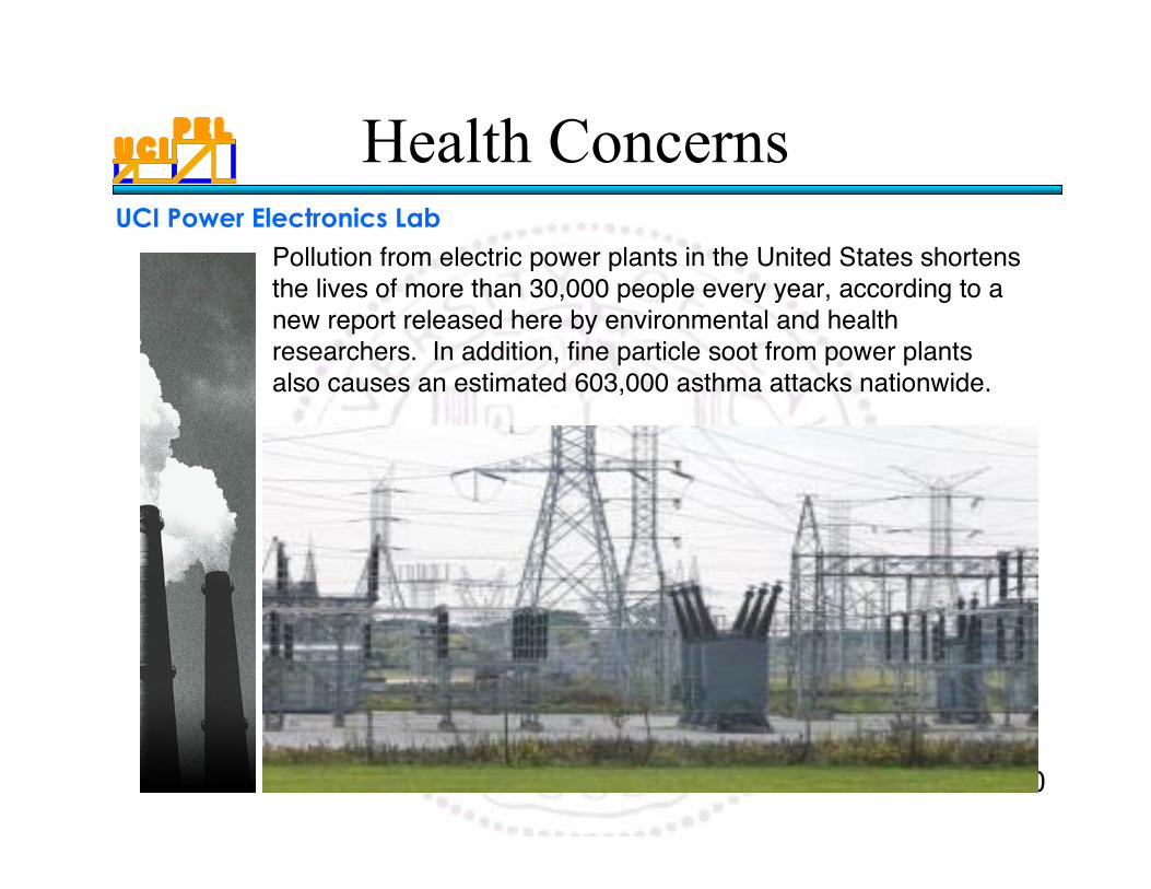
Pollution from electric power plants in the United States shortensthe lives of more than 30,000 people every year, according to anew report released here by environmental and healthresearchers. In addition, fine particle soot from power plantsalso causes an estimated 603,000 asthma attacks nationwide.
Health Concerns
U C IP E L
UCI Power Electronics Lab
11
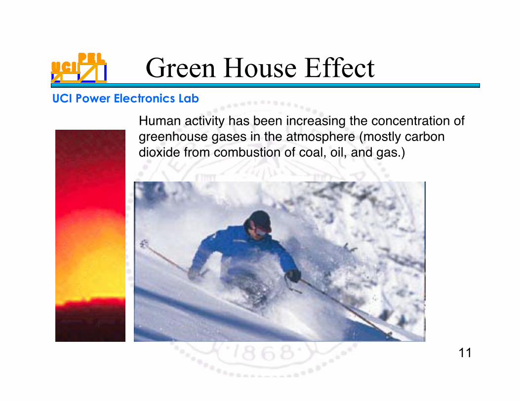
Human activity has been increasing the concentration ofgreenhouse gases in the atmosphere (mostly carbondioxide from combustion of coal, oil, and gas.)
Green House Effect
U C IP E L
UCI Power Electronics Lab
12
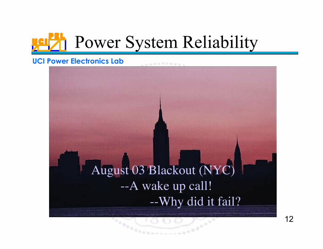
Power System Reliability
August 03 Blackout (NYC)--A wake up call!
--Why did it fail?
U C IP E L
UCI Power Electronics Lab
13
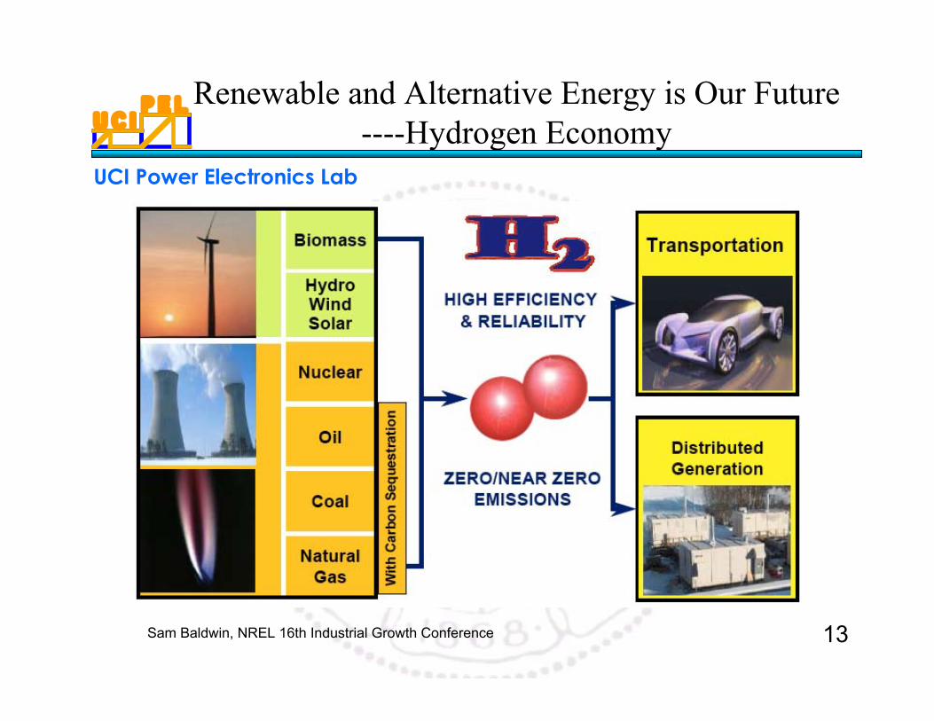
Renewable and Alternative Energy is Our Future----Hydrogen Economy
Sam Baldwin, NREL 16th Industrial Growth Conference
U C IP E L
UCI Power Electronics Lab
14
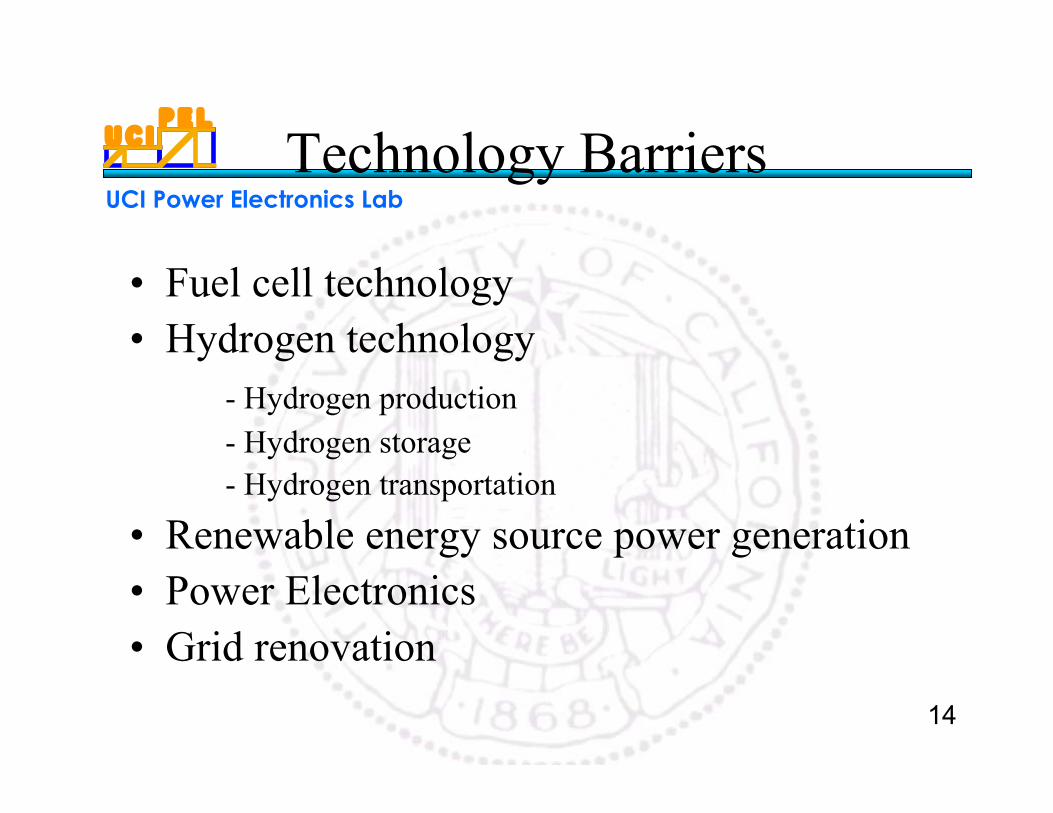
Technology Barriers
• Fuel cell technology• Hydrogen technology
- Hydrogen production- Hydrogen storage- Hydrogen transportation
• Renewable energy source power generation• Power Electronics• Grid renovation
U C IP E L
UCI Power Electronics Lab
15
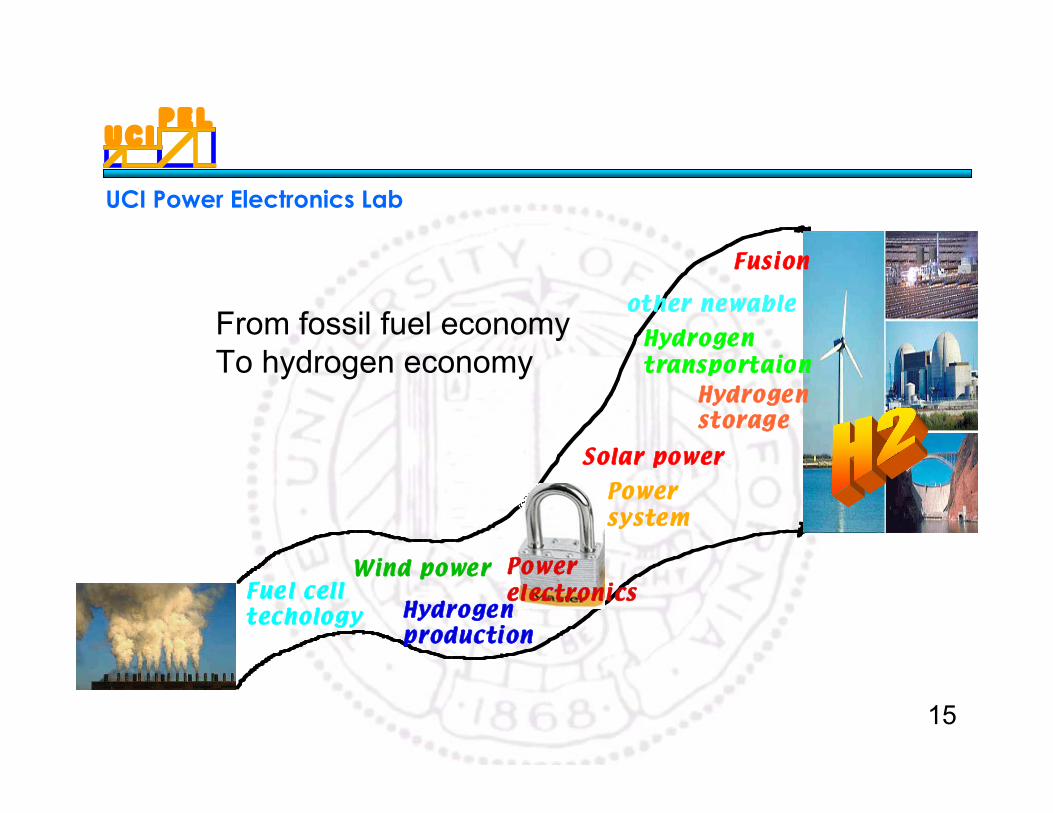
Fuel cell techology Hydrogen
production
Hydrogentransportaion
Hydrogenstorage
Fusion
Power system
Wind power
Solar power
other newable
Powerelectronics
From fossil fuel economyTo hydrogen economy
U C IP E L
UCI Power Electronics Lab
16
II. Fuel Cell Technology
U C IP E L
UCI Power Electronics Lab
17
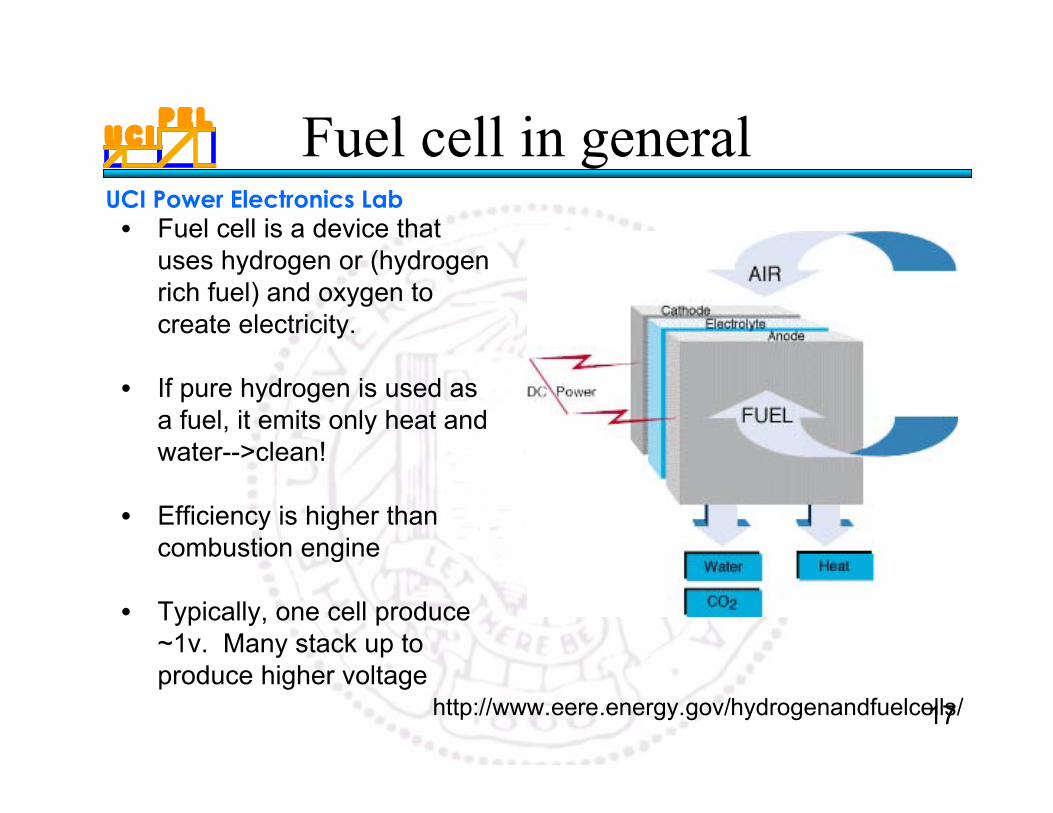
Fuel cell in general• Fuel cell is a device that
uses hydrogen or (hydrogenrich fuel) and oxygen tocreate electricity.
• If pure hydrogen is used asa fuel, it emits only heat andwater-->clean!
• Efficiency is higher thancombustion engine
• Typically, one cell produce~1v. Many stack up toproduce higher voltage
http://www.eere.energy.gov/hydrogenandfuelcells/
U C IP E L
UCI Power Electronics Lab
18
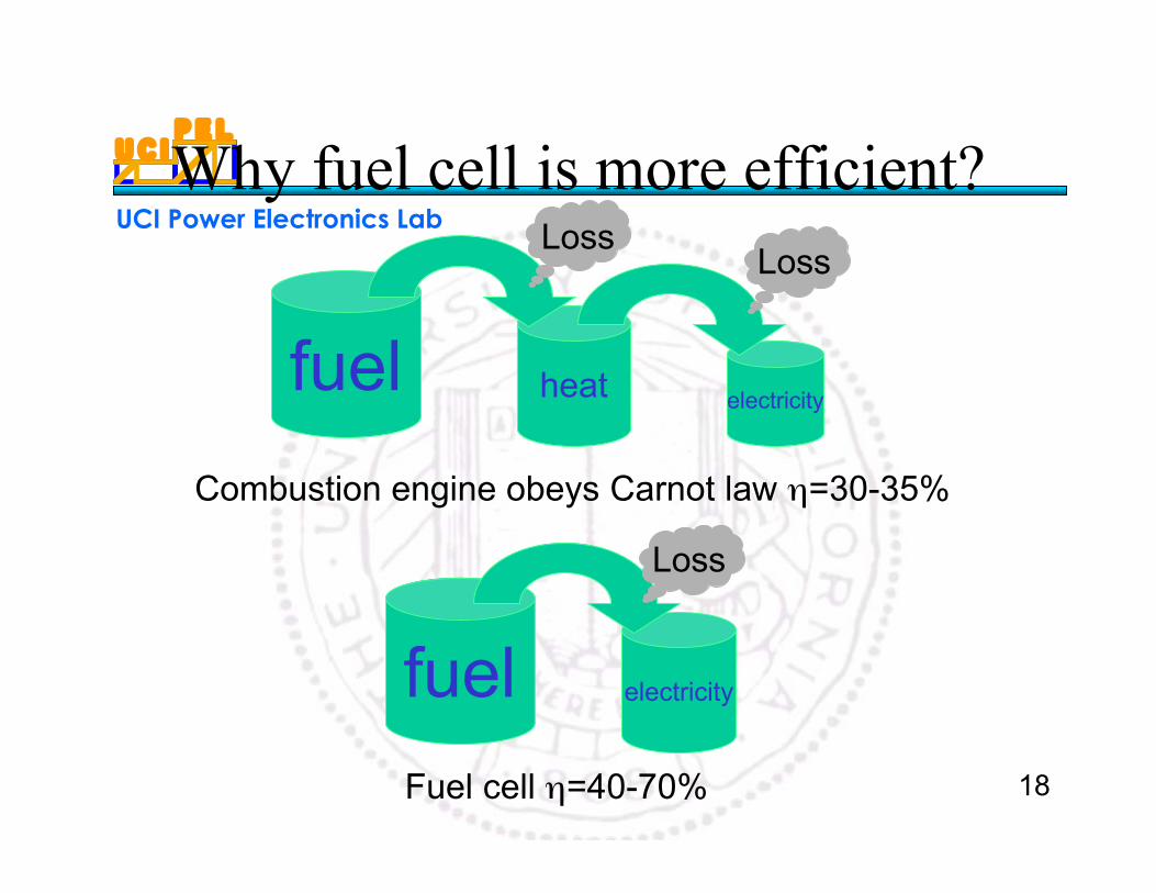
Why fuel cell is more efficient?
fuel
fuel
heat
electricity
electricity
Combustion engine obeys Carnot law η=30-35%
Fuel cell η=40-70%
Loss
LossLoss
U C IP E L
UCI Power Electronics Lab
19
PEMFC configuration
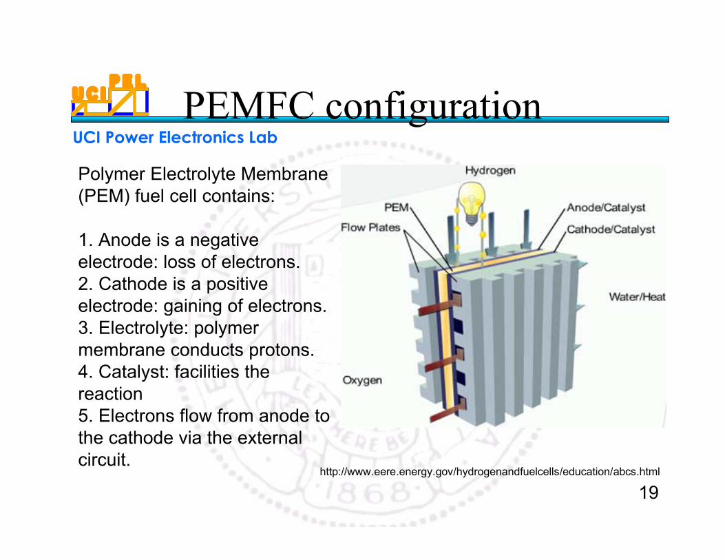
Polymer Electrolyte Membrane(PEM) fuel cell contains:
1. Anode is a negativeelectrode: loss of electrons.2. Cathode is a positiveelectrode: gaining of electrons.3. Electrolyte: polymermembrane conducts protons.4. Catalyst: facilities thereaction5. Electrons flow from anode tothe cathode via the externalcircuit.
http://www.eere.energy.gov/hydrogenandfuelcells/education/abcs.html
U C IP E L
UCI Power Electronics Lab
20
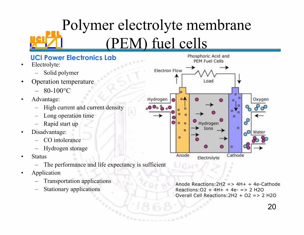
Polymer electrolyte membrane(PEM) fuel cells
• Electrolyte:– Solid polymer
• Operation temperature– 80-100°C
• Advantage:– High current and current density– Long operation time– Rapid start up
• Disadvantage:– CO intolerance– Hydrogen storage
• Status– The performance and life expectancy is sufficient
• Application– Transportation applications– Stationary applications
Anode Reactions:2H2 => 4H+ + 4e-CathodeReactions:O2 + 4H+ + 4e- => 2 H2OOverall Cell Reactions:2H2 + O2 => 2 H2O
U C IP E L
UCI Power Electronics Lab
21
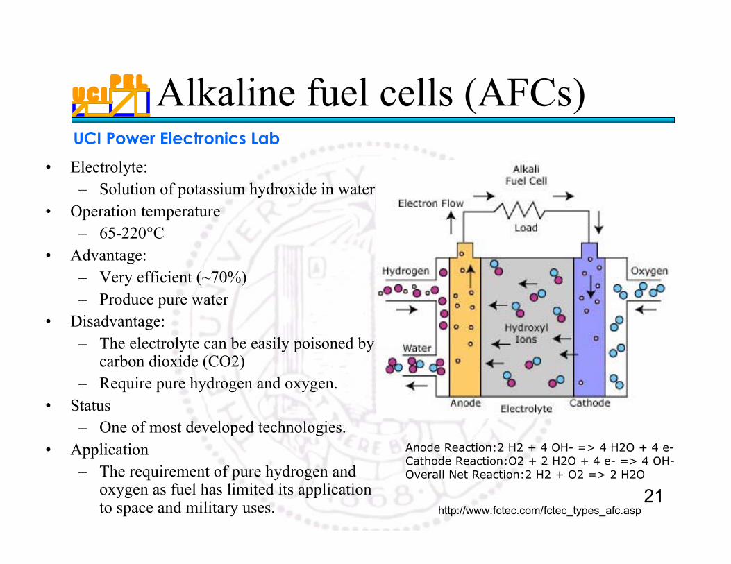
Alkaline fuel cells (AFCs)
• Electrolyte:– Solution of potassium hydroxide in water
• Operation temperature– 65-220°C
• Advantage:– Very efficient (~70%)– Produce pure water
• Disadvantage:– The electrolyte can be easily poisoned by
carbon dioxide (CO2)– Require pure hydrogen and oxygen.
• Status– One of most developed technologies.
• Application– The requirement of pure hydrogen and
oxygen as fuel has limited its applicationto space and military uses.
Anode Reaction:2 H2 + 4 OH- => 4 H2O + 4 e-Cathode Reaction:O2 + 2 H2O + 4 e- => 4 OH-Overall Net Reaction:2 H2 + O2 => 2 H2O
http://www.fctec.com/fctec_types_afc.asp
U C IP E L
UCI Power Electronics Lab
22
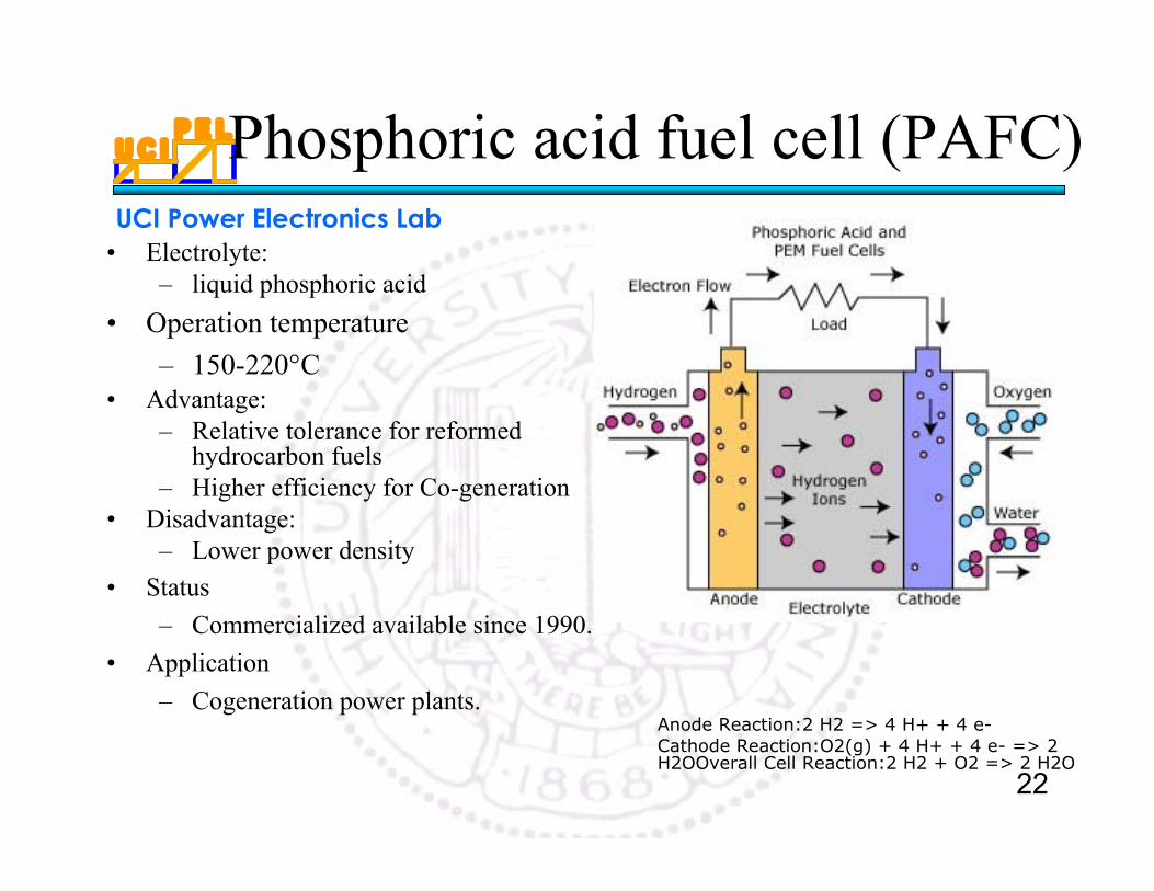
Phosphoric acid fuel cell (PAFC)
• Electrolyte:– liquid phosphoric acid
• Operation temperature
– 150-220°C• Advantage:
– Relative tolerance for reformedhydrocarbon fuels
– Higher efficiency for Co-generation• Disadvantage:
– Lower power density• Status
– Commercialized available since 1990.
• Application
– Cogeneration power plants.Anode Reaction:2 H2 => 4 H+ + 4 e-Cathode Reaction:O2(g) + 4 H+ + 4 e- => 2H2OOverall Cell Reaction:2 H2 + O2 => 2 H2O
U C IP E L
UCI Power Electronics Lab
23
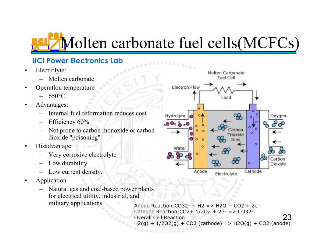
Molten carbonate fuel cells(MCFCs)
• Electrolyte:– Molten carbonate
• Operation temperature– 650°C
• Advantages:– Internal fuel reformation reduces cost– Efficiency 60%– Not prone to carbon monoxide or carbon
dioxide "poisoning"• Disadvantage:
– Very corrosive electrolyte– Low durability– Low current density.
• Application– Natural gas and coal-based power plants
for electrical utility, industrial, andmilitary applications Anode Reaction:CO32- + H2 => H2O + CO2 + 2e-
Cathode Reaction:CO2+ 1/2O2 + 2e- => CO32-Overall Cell Reaction:H2(g) + 1/2O2(g) + CO2 (cathode) => H2O(g) + CO2 (anode)
U C IP E L
UCI Power Electronics Lab
24
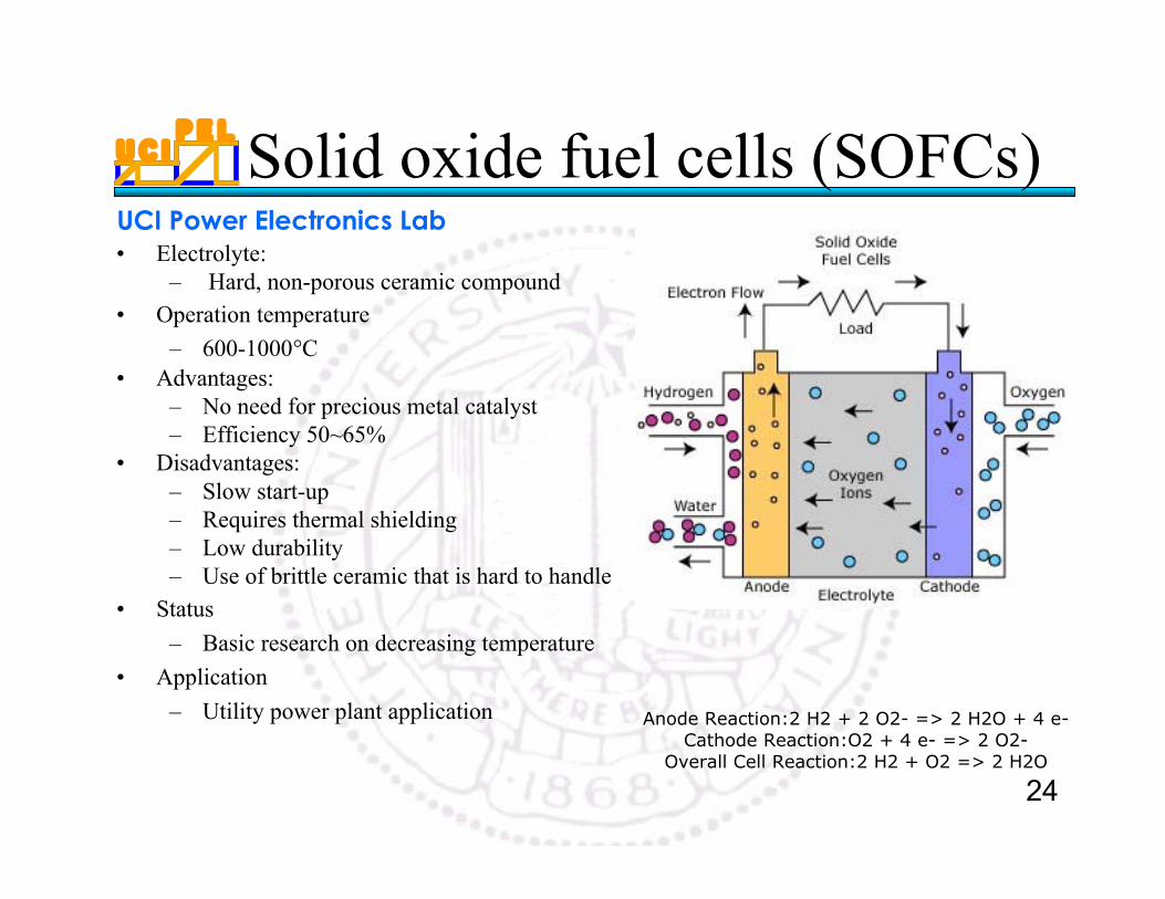
Solid oxide fuel cells (SOFCs)• Electrolyte:
– Hard, non-porous ceramic compound• Operation temperature
– 600-1000°C• Advantages:
– No need for precious metal catalyst– Efficiency 50~65%
• Disadvantages:– Slow start-up– Requires thermal shielding– Low durability– Use of brittle ceramic that is hard to handle
• Status
– Basic research on decreasing temperature
• Application
– Utility power plant application Anode Reaction:2 H2 + 2 O2- => 2 H2O + 4 e-Cathode Reaction:O2 + 4 e- => 2 O2-
Overall Cell Reaction:2 H2 + O2 => 2 H2O
U C IP E L
UCI Power Electronics Lab
25
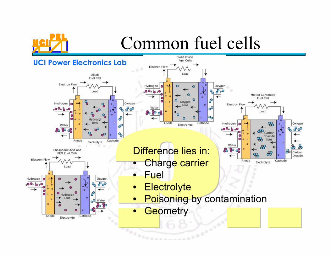
Common fuel cells
Difference lies in:• Charge carrier• Fuel• Electrolyte• Poisoning by contamination• Geometry
U C IP E L
UCI Power Electronics Lab
26
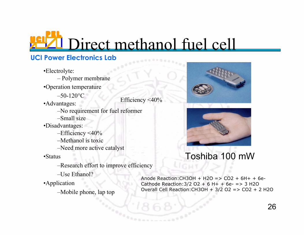
Direct methanol fuel cell
Anode Reaction:CH3OH + H2O => CO2 + 6H+ + 6e-Cathode Reaction:3/2 O2 + 6 H+ + 6e- => 3 H2OOverall Cell Reaction:CH3OH + 3/2 O2 => CO2 + 2 H2O
•Electrolyte: – Polymer membrane
•Operation temperature
–50-120°C •Advantages:
–No requirement for fuel reformer–Small size
•Disadvantages:–Efficiency <40% –Methanol is toxic–Need more active catalyst
•Status
–Research effort to improve efficiency
–Use Ethanol?
•Application
–Mobile phone, lap top
Efficiency <40%
Toshiba 100 mW
U C IP E L
UCI Power Electronics Lab
27
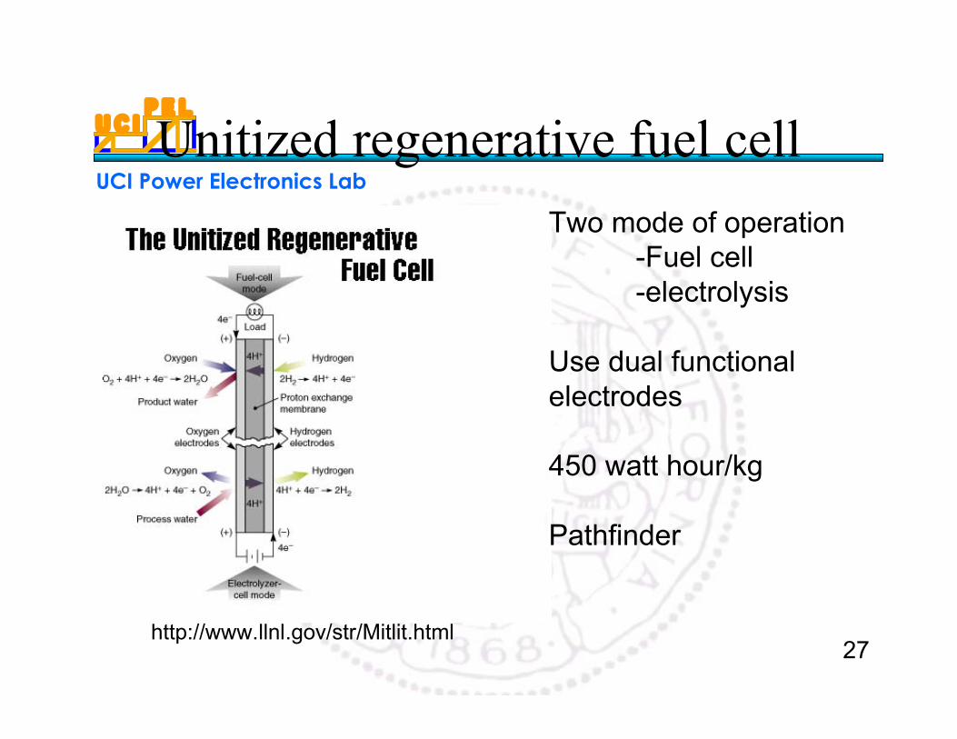
Unitized regenerative fuel cell
Two mode of operation-Fuel cell-electrolysis
Use dual functionalelectrodes
450 watt hour/kg
Pathfinder
http://www.llnl.gov/str/Mitlit.html
U C IP E L
UCI Power Electronics Lab
28
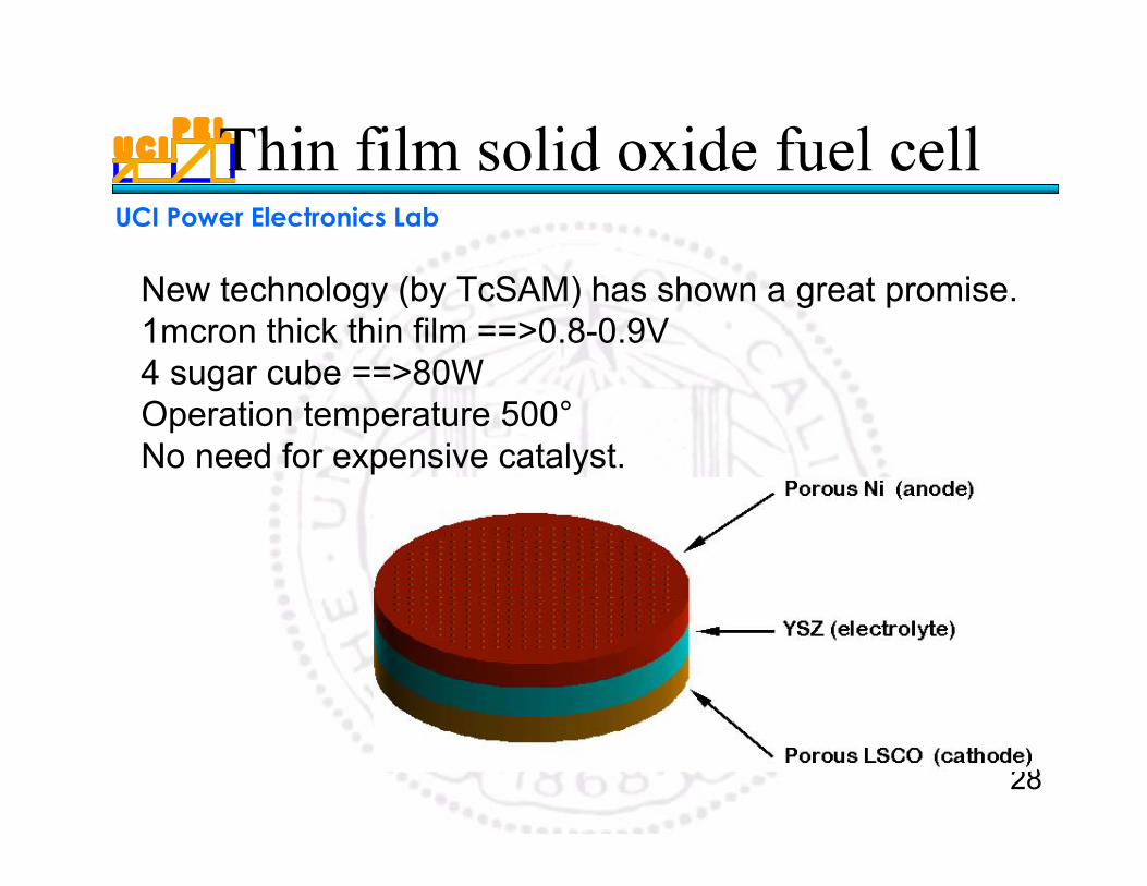
Thin film solid oxide fuel cell
New technology (by TcSAM) has shown a great promise.1mcron thick thin film ==>0.8-0.9V4 sugar cube ==>80WOperation temperature 500° No need for expensive catalyst.
U C IP E L
UCI Power Electronics Lab
29
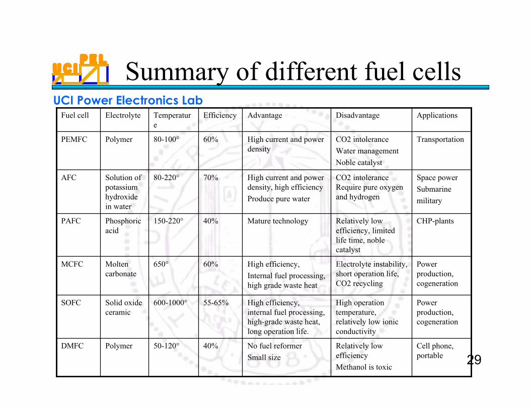
Summary of different fuel cells
TransportationCO2 intolerance
Water management
Noble catalyst
High current and powerdensity
60%80-100°PolymerPEMFC
Cell phone,portable
Relatively lowefficiency
Methanol is toxic
No fuel reformer
Small size
40%50-120°PolymerDMFC
Powerproduction,cogeneration
High operationtemperature,relatively low ionicconductivity
High efficiency,internal fuel processing,high-grade waste heat,long operation life.
55-65%600-1000°Solid oxideceramic
SOFC
Powerproduction,cogeneration
Electrolyte instability,short operation life,CO2 recycling
High efficiency,
Internal fuel processing,high grade waste heat
60%650°Moltencarbonate
MCFC
CHP-plantsRelatively lowefficiency, limitedlife time, noblecatalyst
Mature technology40%150-220°Phosphoricacid
PAFC
Space power
Submarine
military
CO2 intoleranceRequire pure oxygenand hydrogen
High current and powerdensity, high efficiency
Produce pure water
70%80-220°Solution ofpotassiumhydroxidein water
AFC
ApplicationsDisadvantageAdvantageEfficiencyTemperature
ElectrolyteFuel cell
U C IP E L
UCI Power Electronics Lab
30
Fuel Cell Challenge
•Cost reduction•Fuel Flexibility•System Integration•Endurance and Reliability•Infrastructure•Regulation
U C IP E L
UCI Power Electronics Lab
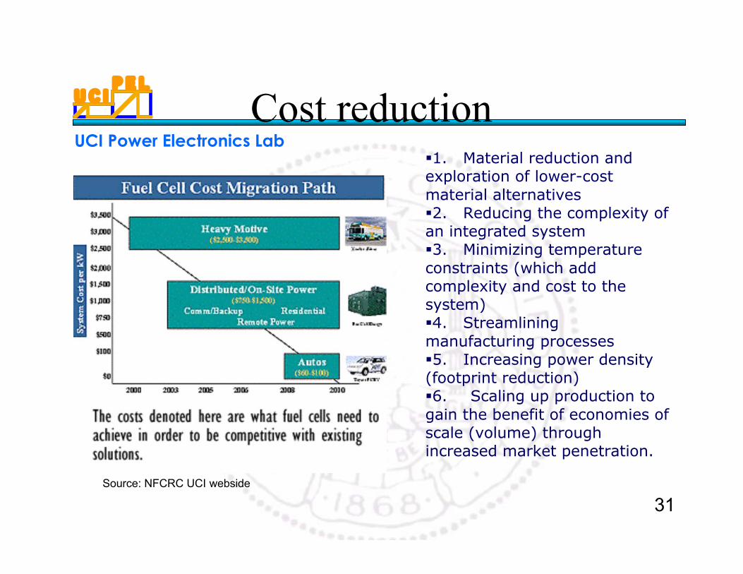
31
Cost reduction1. Material reduction andexploration of lower-costmaterial alternatives2. Reducing the complexity ofan integrated system3. Minimizing temperatureconstraints (which addcomplexity and cost to thesystem)4. Streamliningmanufacturing processes5. Increasing power density(footprint reduction)6. Scaling up production togain the benefit of economies ofscale (volume) throughincreased market penetration.
Source: NFCRC UCI webside
U C IP E L
UCI Power Electronics Lab
32
III Hydrogen Technology
U C IP E L
UCI Power Electronics Lab
33
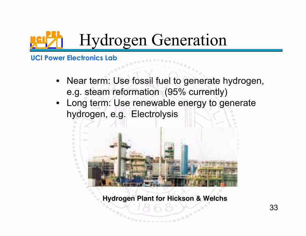
Hydrogen Generation
• Near term: Use fossil fuel to generate hydrogen,e.g. steam reformation (95% currently)
• Long term: Use renewable energy to generatehydrogen, e.g. Electrolysis
Hydrogen Plant for Hickson & Welchs
U C IP E L
UCI Power Electronics Lab
34
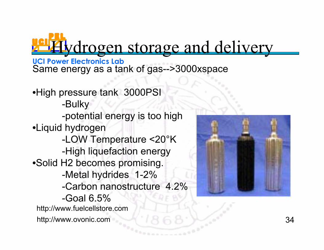
Hydrogen storage and deliverySame energy as a tank of gas-->3000xspace
•High pressure tank 3000PSI-Bulky -potential energy is too high
•Liquid hydrogen-LOW Temperature <20°K-High liquefaction energy
•Solid H2 becomes promising.-Metal hydrides 1-2%-Carbon nanostructure 4.2%-Goal 6.5%
http://www.ovonic.com
http://www.fuelcellstore.com
U C IP E L
UCI Power Electronics Lab
35
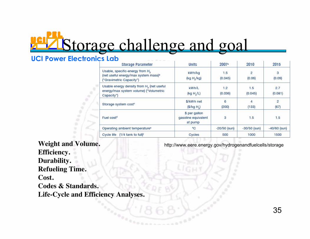
Storage challenge and goal
Weight and Volume. Efficiency. Durability. Refueling Time. Cost. Codes & Standards. Life-Cycle and Efficiency Analyses.
http://www.eere.energy.gov/hydrogenandfuelcells/storage
U C IP E L
UCI Power Electronics Lab
36
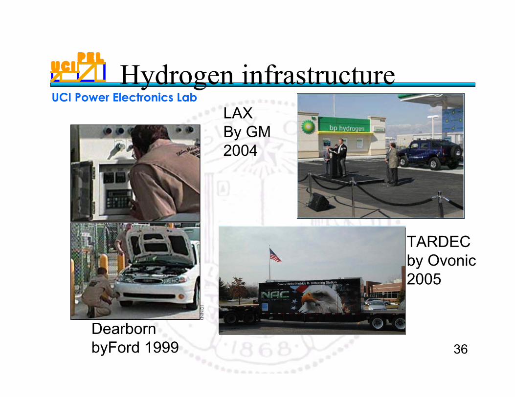
Hydrogen infrastructureLAXBy GM2004
Dearborn byFord 1999
TARDECby Ovonic2005
U C IP E L
UCI Power Electronics Lab
37
IV. Fuel cell applications
U C IP E L
UCI Power Electronics Lab
38
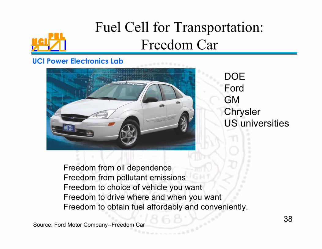
Fuel Cell for Transportation:Freedom Car
DOEFordGMChryslerUS universities
Freedom from oil dependenceFreedom from pollutant emissionsFreedom to choice of vehicle you wantFreedom to drive where and when you wantFreedom to obtain fuel affordably and conveniently.
Source: Ford Motor Company--Freedom Car
U C IP E L
UCI Power Electronics Lab
39
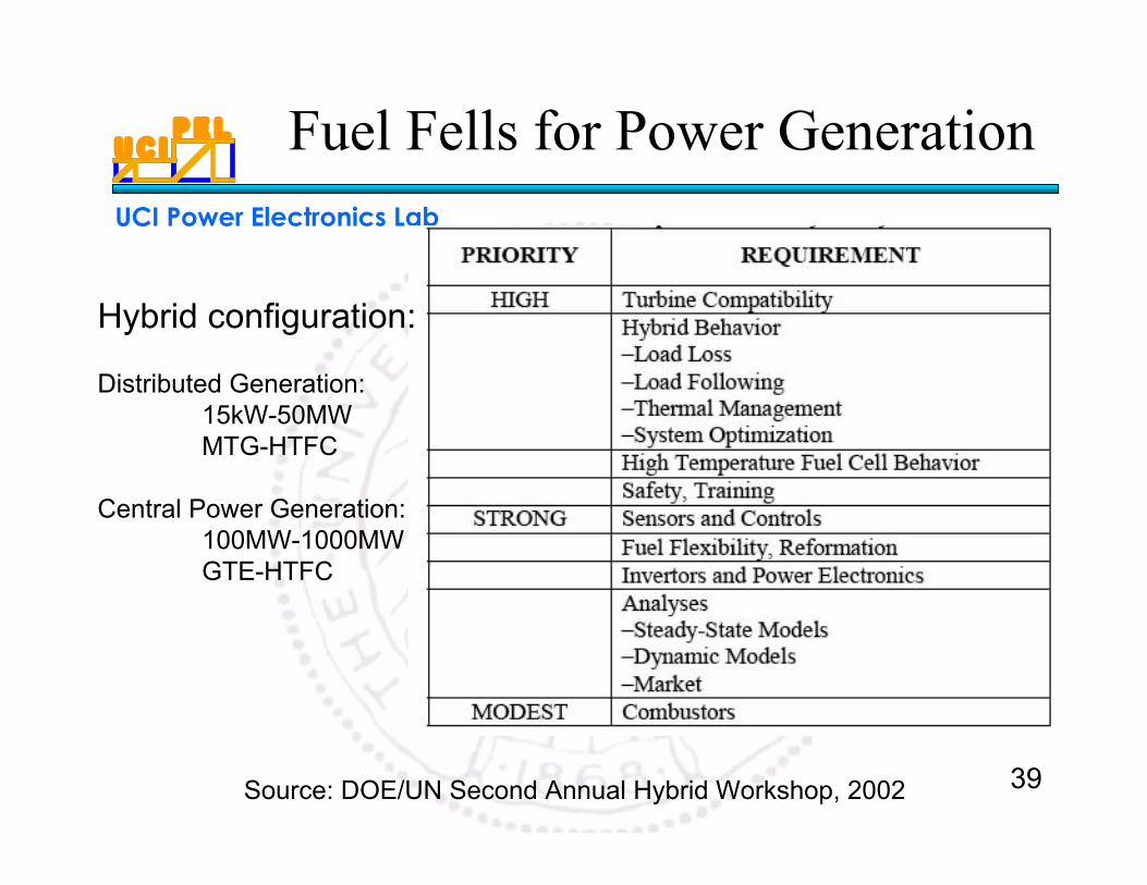
Fuel Fells for Power Generation
Source: DOE/UN Second Annual Hybrid Workshop, 2002
Hybrid configuration:
Distributed Generation: 15kW-50MWMTG-HTFC
Central Power Generation:100MW-1000MWGTE-HTFC
U C IP E L
UCI Power Electronics Lab
40
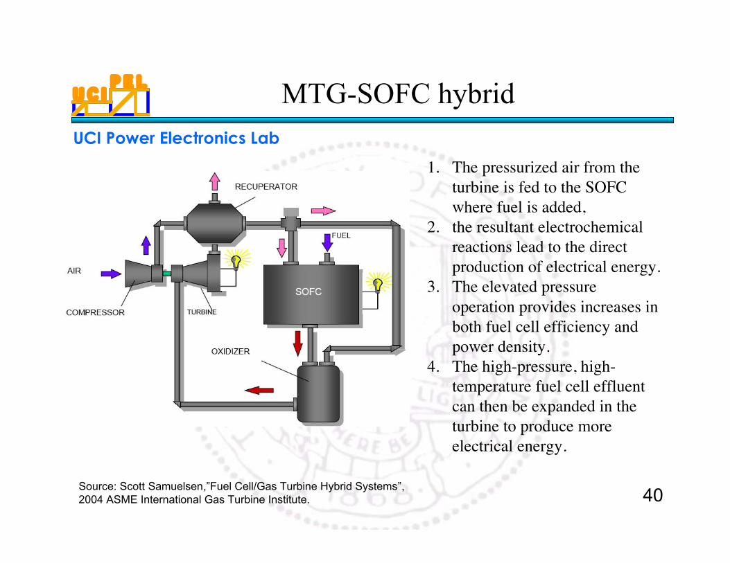
MTG-SOFC hybrid
Source: Scott Samuelsen,”Fuel Cell/Gas Turbine Hybrid Systems”,2004 ASME International Gas Turbine Institute.
1. The pressurized air from theturbine is fed to the SOFCwhere fuel is added,
2. the resultant electrochemicalreactions lead to the directproduction of electrical energy.
3. The elevated pressureoperation provides increases inboth fuel cell efficiency andpower density.
4. The high-pressure, high-temperature fuel cell effluentcan then be expanded in theturbine to produce moreelectrical energy.
U C IP E L
UCI Power Electronics Lab
41
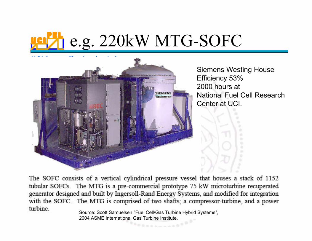
e.g. 220kW MTG-SOFC
Siemens Westing HouseEfficiency 53%2000 hours atNational Fuel Cell ResearchCenter at UCI.
Source: Scott Samuelsen,”Fuel Cell/Gas Turbine Hybrid Systems”,2004 ASME International Gas Turbine Institute.
U C IP E L
UCI Power Electronics Lab
42
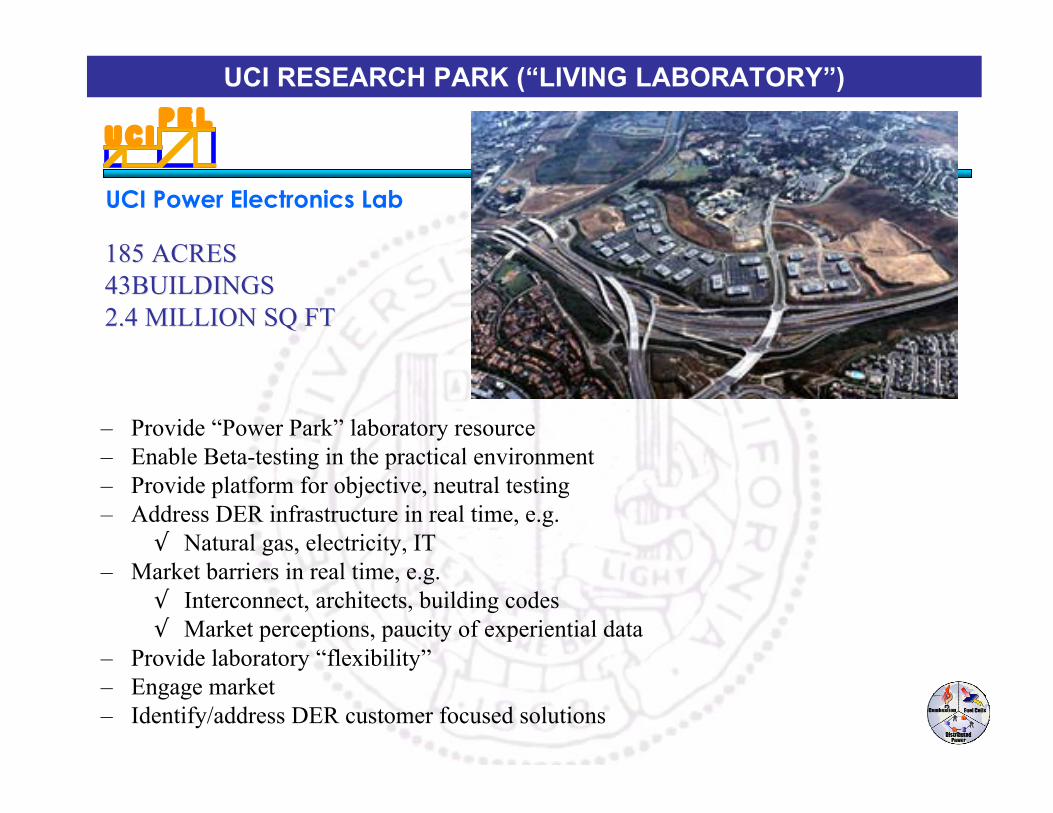
185 ACRES185 ACRES43BUILDINGS43BUILDINGS2.4 MILLION SQ FT2.4 MILLION SQ FT
– Provide “Power Park” laboratory resource– Enable Beta-testing in the practical environment– Provide platform for objective, neutral testing– Address DER infrastructure in real time, e.g.
√ Natural gas, electricity, IT– Market barriers in real time, e.g.
√ Interconnect, architects, building codes√ Market perceptions, paucity of experiential data
– Provide laboratory “flexibility”– Engage market– Identify/address DER customer focused solutions
UCI RESEARCH PARK (“LIVING LABORATORY”)
U C IP E L
UCI Power Electronics Lab
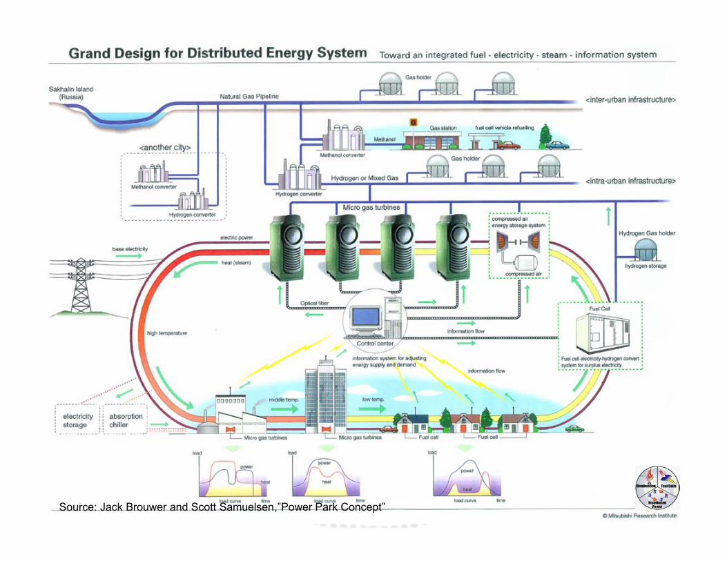
43Source: Jack Brouwer and Scott Samuelsen,”Power Park Concept”
U C IP E L
UCI Power Electronics Lab
44
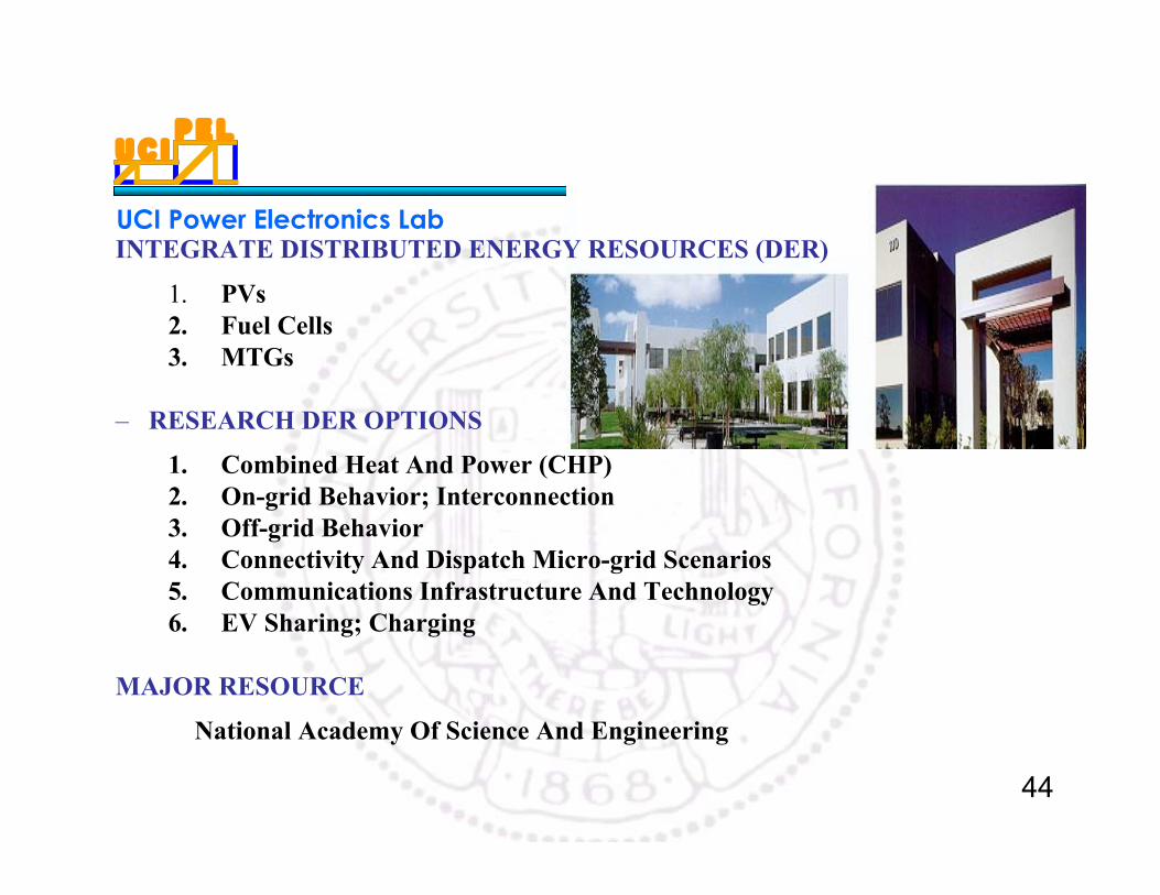
INTEGRATE DISTRIBUTED ENERGY RESOURCES (DER)
1. PVs2. Fuel Cells3. MTGs
– RESEARCH DER OPTIONS
1. Combined Heat And Power (CHP)2. On-grid Behavior; Interconnection3. Off-grid Behavior4. Connectivity And Dispatch Micro-grid Scenarios5. Communications Infrastructure And Technology6. EV Sharing; Charging
MAJOR RESOURCE
National Academy Of Science And Engineering
U C IP E L
UCI Power Electronics Lab
45
V. Power Electronics forHydrogen Power
U C IP E L
UCI Power Electronics Lab
46
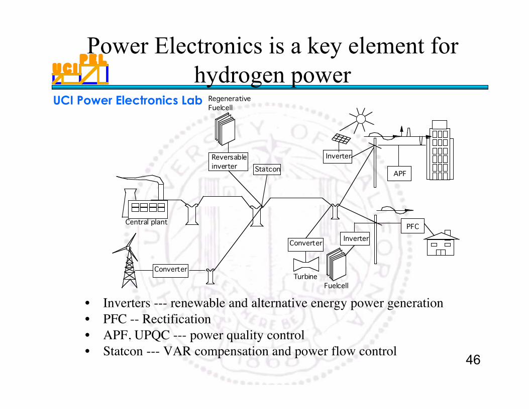
Power Electronics is a key element forhydrogen power
• Inverters --- renewable and alternative energy power generation• PFC -- Rectification• APF, UPQC --- power quality control• Statcon --- VAR compensation and power flow control
Inverter
APF
PFC
TurbineConverter
Converter
Statcon
Fuelcell
RegenerativeFuelcell
Inverter
Reversableinverter
Central plant


![The Trove [multi]/1st... · PATHFINDER RPG CORE RULEBOOK , PATHFINDER RPG BESTI ARY , PATHFINDER RPG BESTIARY 2 , PATHFINDER RPG BESTIARY 3 , PATHFINDER RPG ADVANCED PLAYER S GUID](https://img.pdfslide.us/doc/110x75/60c7beb87d66ea6048574996/the-trove-multi1st-pathfinder-rpg-core-rulebook-pathfinder-rpg-besti-ary.jpg)