Embed Size (px)
Citation preview
Double Ridge Magic-Tee Coupler Using AG and FEM Methods
Fayza BOUSALAH#1, Nour-Eddine BOUKLI-HACENE*2, # Telecommunications Laboratory, Department of Telecommunications
Faculty of Technology, Abou Bakr Belkaid University, Tlemcen, Algeria 1 [email protected]
* 41, boulevard des 24 mètres, El-Kalaa-Tlemcen 13000, Alegria BP 230, Pole Chetouane, 13000 Tlemcen
Abstract— circuit. This is done through the mainstream distribution between two transmission lines close together. This device is used to obtain a sample of attenuated signal transmitted without interrupting the transmission. The fundamental properties of all the directional couplers have a wide bandwidth, directivity of the signal in one direction, and an impedance matching for all output ports. The object of this paper is to present some results of simulation on the coupling and directivity of double ridge waveguide couplers in a field ridge waveguide. This results are obtain by Ansoft HFSS using the Finite Element Method (FEM) calculations and the Genetic Algorithms method, and which show good performance.
Keywords- Double ridge magic-Tee coupler; directional coupler; optimisation; HFSS Software; Genetic Algorithm method; FEM method, E-plane, H-plane.
I. INTRODUCTION
A double ridge waveguide coupler is 4 ports, 180 degree hybrid splitter, realized in field waveguide. It has very similar properties to the rat-race coupler which is usually realized in micro-strip or strip-line. Like all of the coupler and splitter structures, the double ridge waveguide coupler can be used as a power combiner, or a divider. It is ideally lossless, so that all power into one port can be assumed to exit the remaining ports.
The Port 1 is the Σ (sum) port, and is sometimes called the H-plane port, and sometimes called the P-port for "parallel". A signal incident on port 1 equally splits between ports 2 and 3, and the resulting signals are in phase. Ports 2 and 3 are sometimes called the co-linear ports, because they are the only two that are in line with each other. Port 4 is the Δ (difference or delta) port, and is sometimes called the E-plane port, or the S-port for "series". A signal incident on the difference port splits equally between ports 2 and 3, but the resulting signals are 180 degrees out of phase.
This paper illustrates a well known and commonly used high frequency device. The main idea behind the double ridge waveguide coupler is to combine a TE and a TM waveguide splitter. In this particular case port 1 and port 4 are de-coupled, so one can expect S14 and S41 to have very low values. Viewing the electric fields gives a better understanding how the «Double Ridge Waveguide Coupler» works [1], [2].
II. OPERATION OF DOUBLE RIDGE MAGIC-TEE COUPLER
The 4 ports double ridge waveguide coupler is a classic component in microwave engineering. It is defined as a matched 4 ports network with one adjacent port decoupled from any input port, it’s illustrated in figure 1. The waveguide section containing ports 1 and 3 is sometimes referred to as the primary waveguide, while that containing ports 2 and 4 is denoted the secondary waveguide [3]. A scrutiny of the symmetry of this sort of network suggests the possibility of reducing the entries of the scattering matrix to linear combinations of odd and even modes. This may be done by taking ports 1 and 2 as a typical pair of input ports and ports 3 and 4 as typical output ports. The scattering matrix of the ideal, symmetric and lossless network with port 2 decoupled from port 1 is given in the usual way by:
S=
00 00 00 00
The relationship between the transmitted (S31) and coupled (S41) coefficients is given by the unitary condition:
S31S31* + S41S41* =1 (1) | S31|2+| S31|2=1 (2) S31S41* + S31S41* =0 (3)
One solution is: S41=ϳβ and S31 = α The performance of any non ideal directional coupler is defined in terms of coupling and directivity factors:
e-ISSN : 0975-4024 Fayza Bousalah et al. / International Journal of Engineering and Technology (IJET)
p-ISSN : 2319-8613 Vol 8 No 1 Feb-Mar 2016 454
= 20 ( ) (4)
é = 20 ( / ) (5)
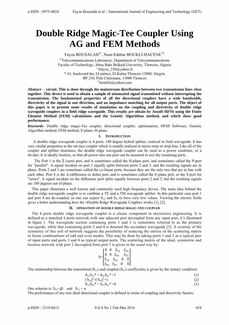
Fig.1. Schematic diagrams of 4 ports of double ridge waveguide coupler.
III. SIMULATION AND OPTIMIZATION OF DOUBLE RIDGE WAVEGUIDE COUPLER AND MAGIC-TEE COUPLER
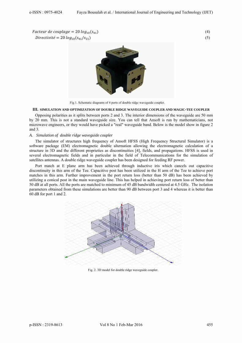
Opposing polarities as it splits between ports 2 and 3. The interior dimensions of the waveguide are 50 mm by 20 mm. This is not a standard waveguide size. You can tell that Ansoft is run by mathematicians, not microwave engineers, or they would have picked a "real" waveguide band. Below is the model show in figure 2 and 3.
A. Simulation of double ridge waveguide coupler The simulator of structures high frequency of Ansoft HFSS (High Frequency Structural Simulator) is a
software package (EM) electromagnetic double alternation allowing the electromagnetic calculation of a structure in 3D and the different proprieties as discontinuities [4], fields, and propagations. HFSS is used in several electromagnetic fields and in particular in the field of Telecommunications for the simulation of satellites antennas. A double ridge waveguide coupler has been designed for feeding RF power.
Port match at E plane arm has been achieved through inductive iris which cancels out capacitive discontinuity in this arm of the Tee. Capacitive post has been utilized in the H arm of the Tee to achieve port matches in this arm. Further improvement in the port return loss (better than 50 dB) has been achieved by utilizing a conical post in the main waveguide line. This has helped in achieving port return loss of better than 50 dB at all ports. All the ports are matched to minimum of 45 dB bandwidth centered at 4.5 GHz. The isolation parameters obtained from these simulations are better than 90 dB between port 3 and 4 whereas it is better than 60 dB for port 1 and 2.
Fig. 2. 3D model for double ridge waveguide coupler.
e-ISSN : 0975-4024 Fayza Bousalah et al. / International Journal of Engineering and Technology (IJET)
p-ISSN : 2319-8613 Vol 8 No 1 Feb-Mar 2016 455
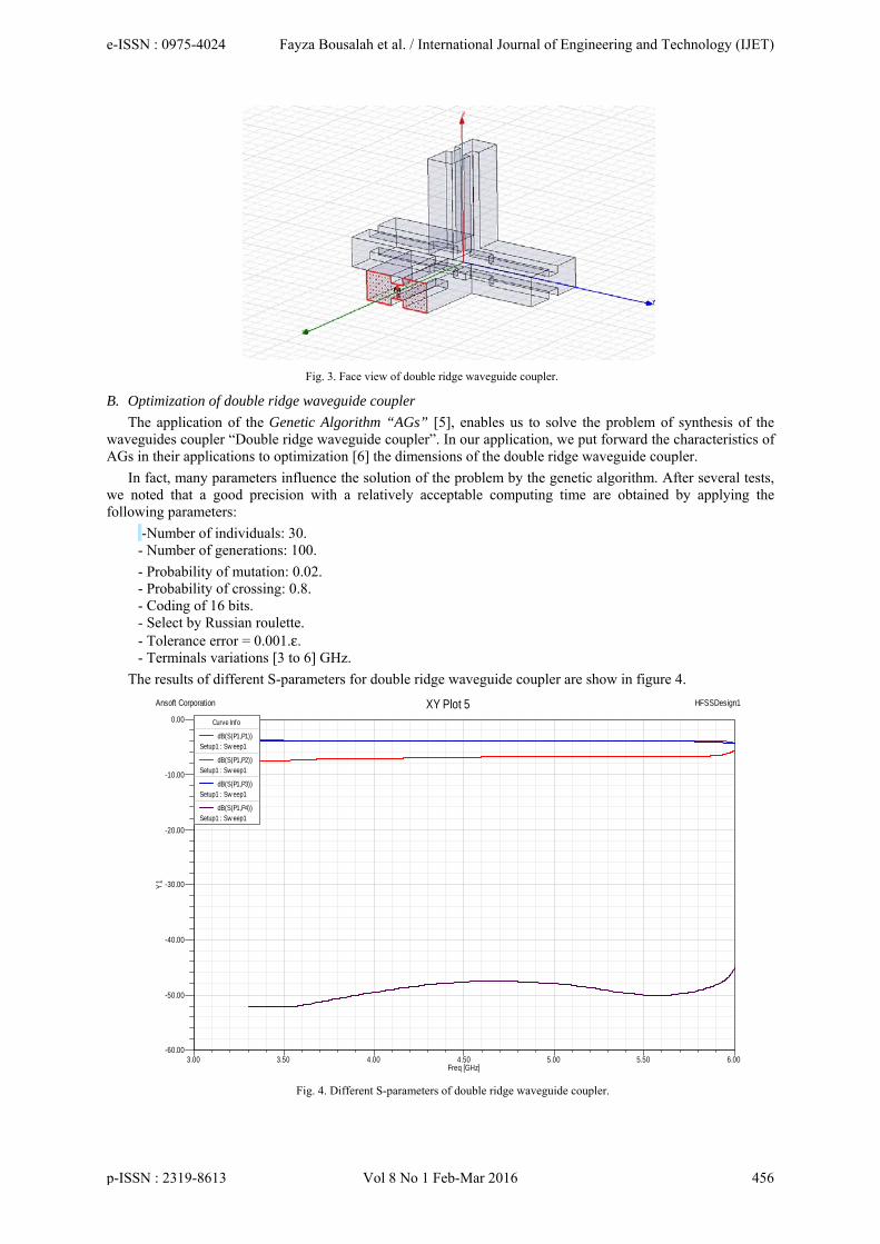
Fig. 3. Face view of double ridge waveguide coupler.
B. Optimization of double ridge waveguide coupler The application of the Genetic Algorithm “AGs” [5], enables us to solve the problem of synthesis of the
waveguides coupler “Double ridge waveguide coupler”. In our application, we put forward the characteristics of AGs in their applications to optimization [6] the dimensions of the double ridge waveguide coupler.
In fact, many parameters influence the solution of the problem by the genetic algorithm. After several tests, we noted that a good precision with a relatively acceptable computing time are obtained by applying the following parameters:
-Number of individuals: 30. - Number of generations: 100.
- Probability of mutation: 0.02. - Probability of crossing: 0.8. - Coding of 16 bits. - Select by Russian roulette. - Tolerance error = 0.001.ε. - Terminals variations [3 to 6] GHz.
The results of different S-parameters for double ridge waveguide coupler are show in figure 4.
Fig. 4. Different S-parameters of double ridge waveguide coupler.
3.00 3.50 4.00 4.50 5.00 5.50 6.00Freq [GHz]
-60.00
-50.00
-40.00
-30.00
-20.00
-10.00
0.00
Y1
Ansoft Corporation HFSSDesign1XY Plot 5Curve Info
dB(S(P1,P1))Setup1 : Sw eep1
dB(S(P1,P2))Setup1 : Sw eep1
dB(S(P1,P3))Setup1 : Sw eep1
dB(S(P1,P4))Setup1 : Sw eep1
e-ISSN : 0975-4024 Fayza Bousalah et al. / International Journal of Engineering and Technology (IJET)
p-ISSN : 2319-8613 Vol 8 No 1 Feb-Mar 2016 456
The S-parameters of the four ports network, including the transmission coefficient between sum and delta ports, which is better than -6.80 dB. The input match S11 could be better, which would require some tuning. Guess that's why you'd never buy a double ridge waveguide coupler from Ansoft HFSS [7], [8]. He suggests adding tuning to the Σ and Δ arms.
Without any matching components placed in the waveguide port of the double ridge waveguide coupler, the return losses for each port of the double ridge waveguide coupler [9] has been observed in HFSS simulation software. The return loss for only port 1 is shown in figure 5. It can also be found that for other ports also return losses are below -6.80 dB.
Fig. 5. Return loss at port 1 (S11) dB
The figure 6 and 7, illustrate the coefficient of transmission S12 and S13.
Fig. 6. The coefficient of transmission between port 1 and port 2 (S12) dB.
3.00 3.50 4.00 4.50 5.00 5.50 6.00Freq [GHz]
-8.00
-7.50
-7.00
-6.50
-6.00
-5.50
dB(S
(P1,
P1))
Ansoft Corporation HFSSDesign1XY Plot 1Curve Info
dB(S(P1,P1))Setup1 : Sw eep1
3.00 3.50 4.00 4.50 5.00 5.50 6.00Freq [GHz]
-4.30
-4.20
-4.10
-4.00
-3.90
-3.80
-3.70
dB(S
(P1,
P2)
)
Ansoft Corporation HFSSDesign1XY Plot 2Curve Info
dB(S(P1,P2))Setup1 : Sw eep1
e-ISSN : 0975-4024 Fayza Bousalah et al. / International Journal of Engineering and Technology (IJET)
p-ISSN : 2319-8613 Vol 8 No 1 Feb-Mar 2016 457
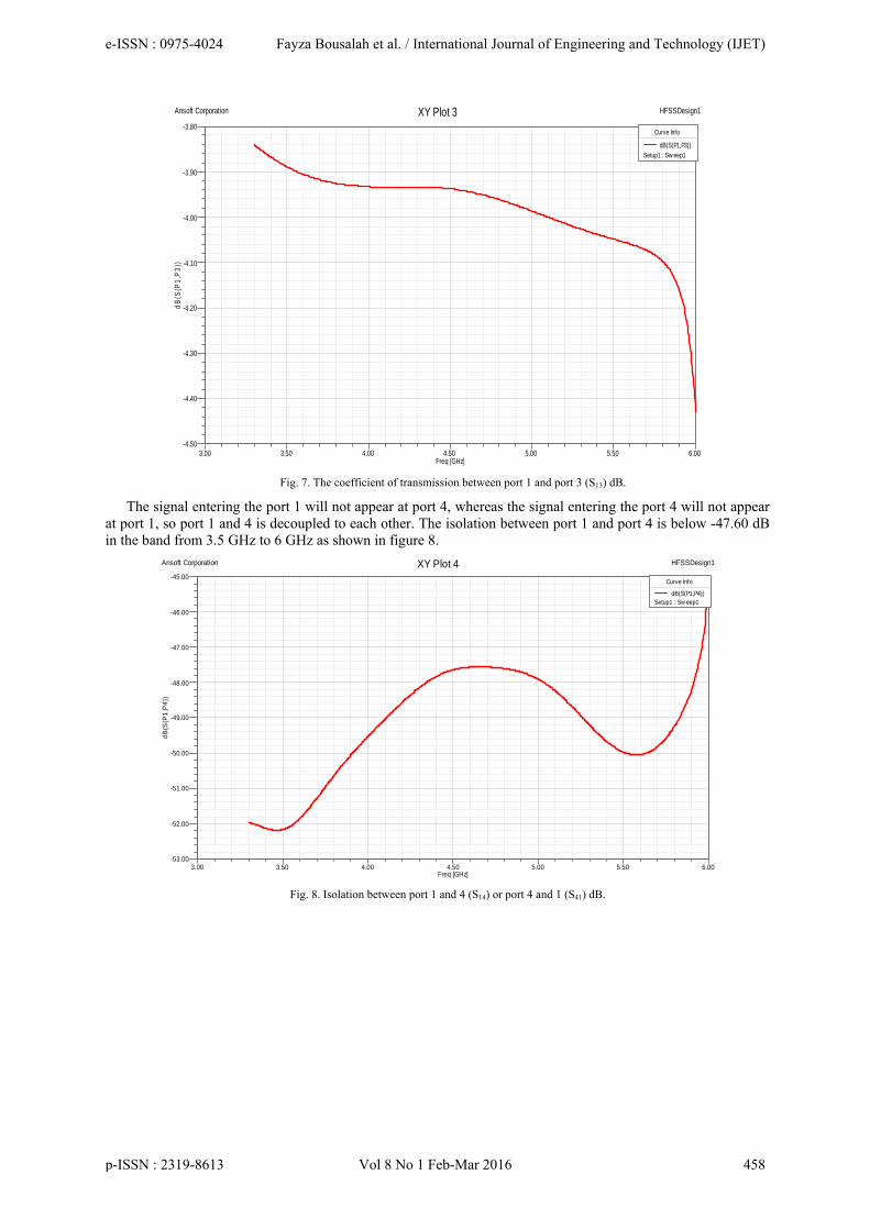
Fig. 7. The coefficient of transmission between port 1 and port 3 (S13) dB.
The signal entering the port 1 will not appear at port 4, whereas the signal entering the port 4 will not appear at port 1, so port 1 and 4 is decoupled to each other. The isolation between port 1 and port 4 is below -47.60 dB in the band from 3.5 GHz to 6 GHz as shown in figure 8.
Fig. 8. Isolation between port 1 and 4 (S14) or port 4 and 1 (S41) dB.
3.00 3.50 4.00 4.50 5.00 5.50 6.00Freq [GHz]
-4.50
-4.40
-4.30
-4.20
-4.10
-4.00
-3.90
-3.80
dB(S
(P1,
P3)
)
Ansoft Corporation HFSSDesign1XY Plot 3Curve Info
dB(S(P1,P3))Setup1 : Sw eep1
3.00 3.50 4.00 4.50 5.00 5.50 6.00Freq [GHz]
-53.00
-52.00
-51.00
-50.00
-49.00
-48.00
-47.00
-46.00
-45.00
dB(S
(P1,
P4))
Ansoft Corporation HFSSDesign1XY Plot 4Curve Info
dB(S(P1,P4))Setup1 : Sw eep1
e-ISSN : 0975-4024 Fayza Bousalah et al. / International Journal of Engineering and Technology (IJET)
p-ISSN : 2319-8613 Vol 8 No 1 Feb-Mar 2016 458
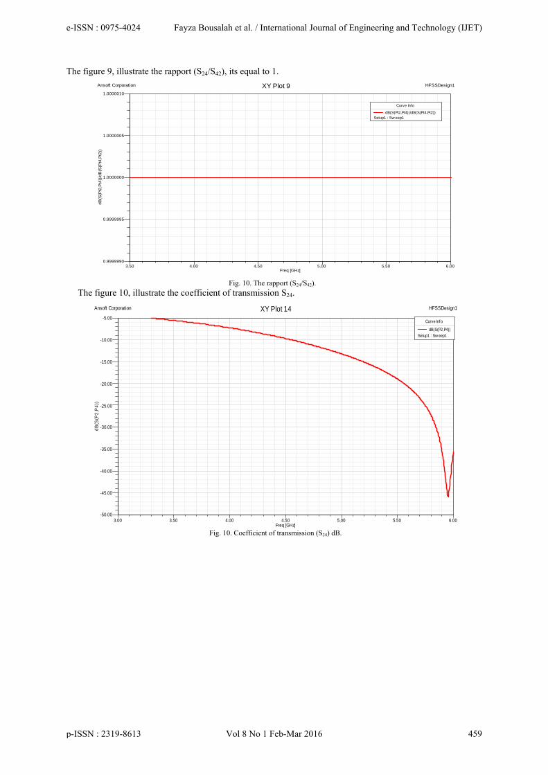
The figure 9, illustrate the rapport (S24/S42), its equal to 1.
Fig. 10. The rapport (S24/S42).
The figure 10, illustrate the coefficient of transmission S24.
Fig. 10. Coefficient of transmission (S24) dB.
3.50 4.00 4.50 5.00 5.50 6.00Freq [GHz]
0.9999990
0.9999995
1.0000000
1.0000005
1.0000010dB
(S(P
t2,P
t4))/
dB(S
(Pt4
,Pt2
))
Ansoft Corporation HFSSDesign1XY Plot 9
Curve Info
dB(S(Pt2,Pt4))/dB(S(Pt4,Pt2))Setup1 : Sw eep1
3.00 3.50 4.00 4.50 5.00 5.50 6.00Freq [GHz]
-50.00
-45.00
-40.00
-35.00
-30.00
-25.00
-20.00
-15.00
-10.00
-5.00
dB(S
(P2,
P4)
)
Ansoft Corporation HFSSDesign1XY Plot 14Curve Info
dB(S(P2,P4))Setup1 : Sw eep1
e-ISSN : 0975-4024 Fayza Bousalah et al. / International Journal of Engineering and Technology (IJET)
p-ISSN : 2319-8613 Vol 8 No 1 Feb-Mar 2016 459
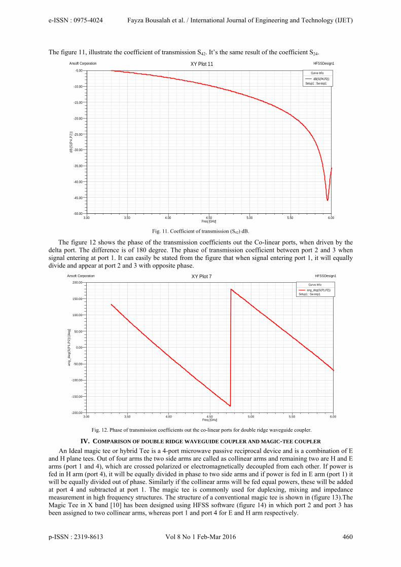
The figure 11, illustrate the coefficient of transmission S42. It’s the same result of the coefficient S24.
Fig. 11. Coefficient of transmission (S42) dB.
The figure 12 shows the phase of the transmission coefficients out the Co-linear ports, when driven by the delta port. The difference is of 180 degree. The phase of transmission coefficient between port 2 and 3 when signal entering at port 1. It can easily be stated from the figure that when signal entering port 1, it will equally divide and appear at port 2 and 3 with opposite phase.
Fig. 12. Phase of transmission coefficients out the co-linear ports for double ridge waveguide coupler.
IV. COMPARISON OF DOUBLE RIDGE WAVEGUIDE COUPLER AND MAGIC-TEE COUPLER
An Ideal magic tee or hybrid Tee is a 4-port microwave passive reciprocal device and is a combination of E and H plane tees. Out of four arms the two side arms are called as collinear arms and remaining two are H and E arms (port 1 and 4), which are crossed polarized or electromagnetically decoupled from each other. If power is fed in H arm (port 4), it will be equally divided in phase to two side arms and if power is fed in E arm (port 1) it will be equally divided out of phase. Similarly if the collinear arms will be fed equal powers, these will be added at port 4 and subtracted at port 1. The magic tee is commonly used for duplexing, mixing and impedance measurement in high frequency structures. The structure of a conventional magic tee is shown in (figure 13).The Magic Tee in X band [10] has been designed using HFSS software (figure 14) in which port 2 and port 3 has been assigned to two collinear arms, whereas port 1 and port 4 for E and H arm respectively.
3.00 3.50 4.00 4.50 5.00 5.50 6.00Freq [GHz]
-50.00
-45.00
-40.00
-35.00
-30.00
-25.00
-20.00
-15.00
-10.00
-5.00dB
(S(P
4,P
2))
Ansoft Corporation HFSSDesign1XY Plot 11Curve Info
dB(S(P4,P2))Setup1 : Sw eep1
3.00 3.50 4.00 4.50 5.00 5.50 6.00Freq [GHz]
-200.00
-150.00
-100.00
-50.00
0.00
50.00
100.00
150.00
200.00
ang_
deg(
S(P
1,P
2)) [
deg]
Ansoft Corporation HFSSDesign1XY Plot 7Curve Info
ang_deg(S(P1,P2))Setup1 : Sw eep1
e-ISSN : 0975-4024 Fayza Bousalah et al. / International Journal of Engineering and Technology (IJET)
p-ISSN : 2319-8613 Vol 8 No 1 Feb-Mar 2016 460
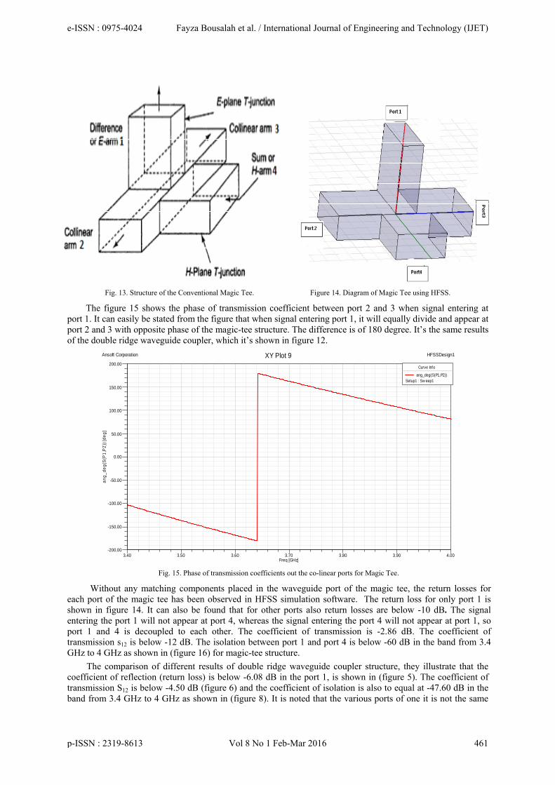
Fig. 13. Structure of the Conventional Magic Tee. Figure 14. Diagram of Magic Tee using HFSS.
The figure 15 shows the phase of transmission coefficient between port 2 and 3 when signal entering at port 1. It can easily be stated from the figure that when signal entering port 1, it will equally divide and appear at port 2 and 3 with opposite phase of the magic-tee structure. The difference is of 180 degree. It’s the same results of the double ridge waveguide coupler, which it’s shown in figure 12.
Fig. 15. Phase of transmission coefficients out the co-linear ports for Magic Tee.
Without any matching components placed in the waveguide port of the magic tee, the return losses for each port of the magic tee has been observed in HFSS simulation software. The return loss for only port 1 is shown in figure 14. It can also be found that for other ports also return losses are below -10 dB. The signal entering the port 1 will not appear at port 4, whereas the signal entering the port 4 will not appear at port 1, so port 1 and 4 is decoupled to each other. The coefficient of transmission is -2.86 dB. The coefficient of transmission s12 is below -12 dB. The isolation between port 1 and port 4 is below -60 dB in the band from 3.4 GHz to 4 GHz as shown in (figure 16) for magic-tee structure.
The comparison of different results of double ridge waveguide coupler structure, they illustrate that the coefficient of reflection (return loss) is below -6.08 dB in the port 1, is shown in (figure 5). The coefficient of transmission S12 is below -4.50 dB (figure 6) and the coefficient of isolation is also to equal at -47.60 dB in the band from 3.4 GHz to 4 GHz as shown in (figure 8). It is noted that the various ports of one it is not the same
3.40 3.50 3.60 3.70 3.80 3.90 4.00Freq [GHz]
-200.00
-150.00
-100.00
-50.00
0.00
50.00
100.00
150.00
200.00
ang_
deg(
S(P
1,P
2)) [
deg]
Ansoft Corporation HFSSDesign1XY Plot 9Curve Info
ang_deg(S(P1,P2))Setup1 : Sw eep1
e-ISSN : 0975-4024 Fayza Bousalah et al. / International Journal of Engineering and Technology (IJET)
p-ISSN : 2319-8613 Vol 8 No 1 Feb-Mar 2016 461
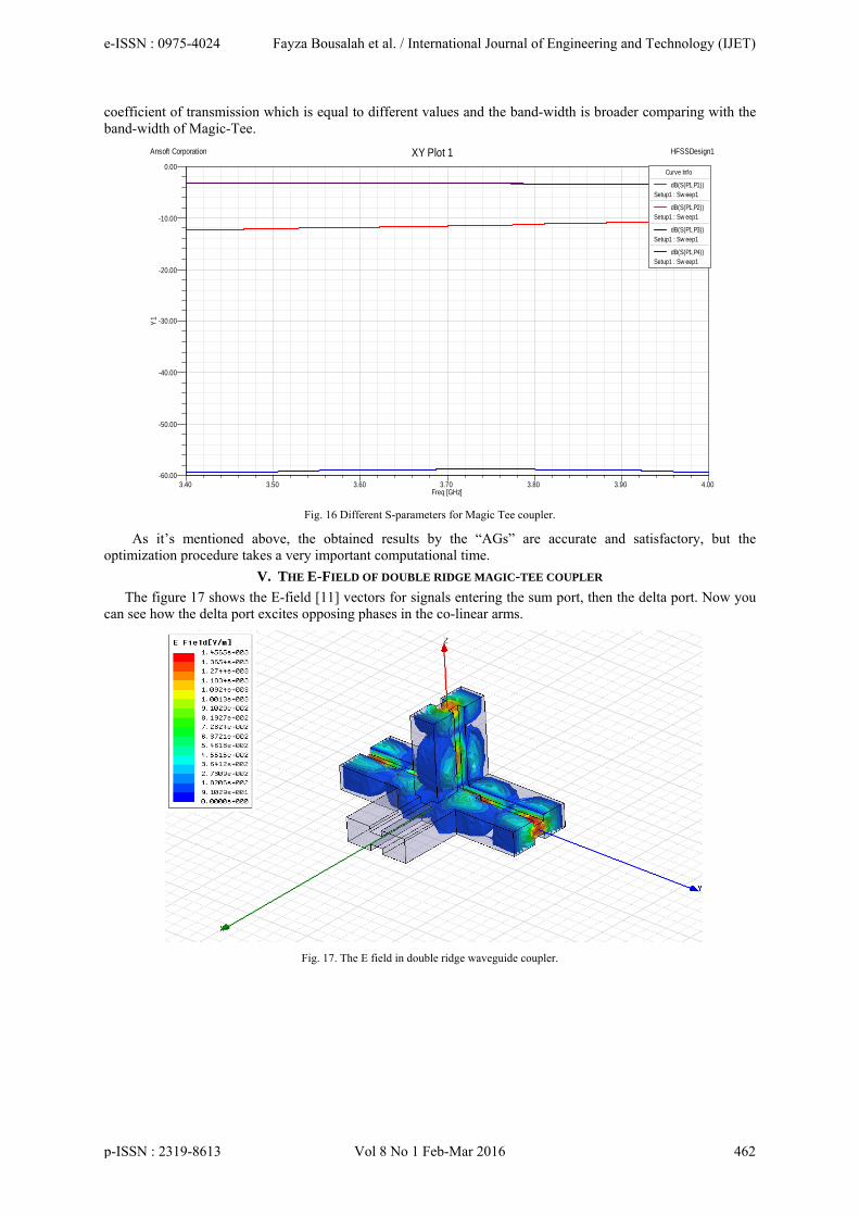
coefficient of transmission which is equal to different values and the band-width is broader comparing with the band-width of Magic-Tee.
Fig. 16 Different S-parameters for Magic Tee coupler.
As it’s mentioned above, the obtained results by the “AGs” are accurate and satisfactory, but the optimization procedure takes a very important computational time.
V. THE E-FIELD OF DOUBLE RIDGE MAGIC-TEE COUPLER
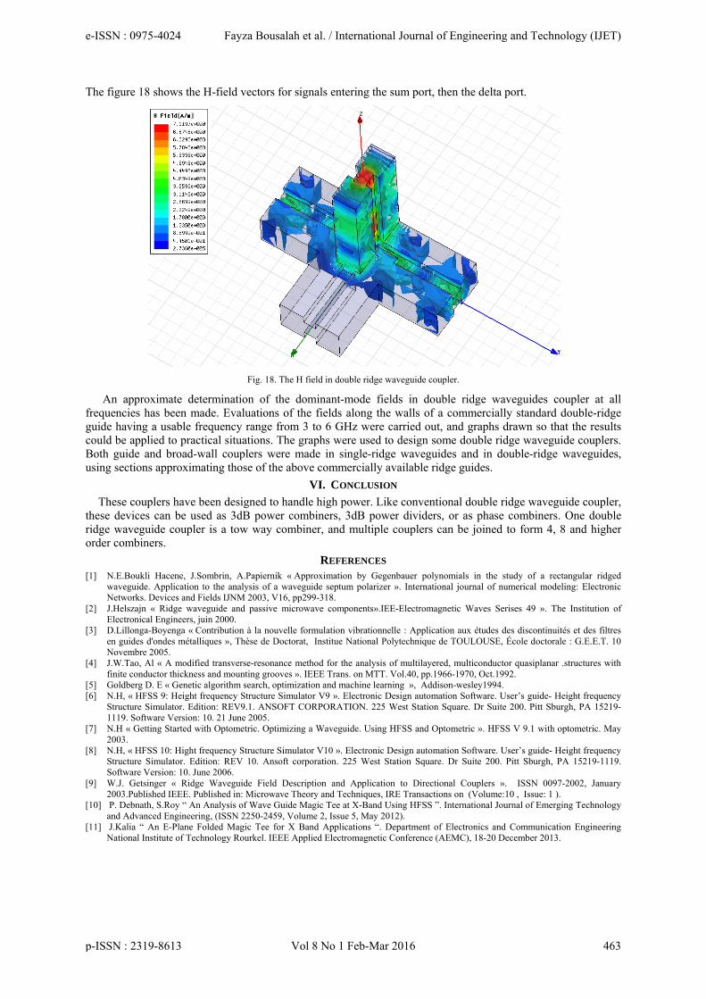
The figure 17 shows the E-field [11] vectors for signals entering the sum port, then the delta port. Now you can see how the delta port excites opposing phases in the co-linear arms.
Fig. 17. The E field in double ridge waveguide coupler.
3.40 3.50 3.60 3.70 3.80 3.90 4.00Freq [GHz]
-60.00
-50.00
-40.00
-30.00
-20.00
-10.00
0.00
Y1
Ansoft Corporation HFSSDesign1XY Plot 1Curve Info
dB(S(P1,P1))Setup1 : Sw eep1
dB(S(P1,P2))Setup1 : Sw eep1
dB(S(P1,P3))Setup1 : Sw eep1
dB(S(P1,P4))Setup1 : Sw eep1
e-ISSN : 0975-4024 Fayza Bousalah et al. / International Journal of Engineering and Technology (IJET)
p-ISSN : 2319-8613 Vol 8 No 1 Feb-Mar 2016 462
The figure 18 shows the H-field vectors for signals entering the sum port, then the delta port.
Fig. 18. The H field in double ridge waveguide coupler.
An approximate determination of the dominant-mode fields in double ridge waveguides coupler at all frequencies has been made. Evaluations of the fields along the walls of a commercially standard double-ridge guide having a usable frequency range from 3 to 6 GHz were carried out, and graphs drawn so that the results could be applied to practical situations. The graphs were used to design some double ridge waveguide couplers. Both guide and broad-wall couplers were made in single-ridge waveguides and in double-ridge waveguides, using sections approximating those of the above commercially available ridge guides.
VI. CONCLUSION
These couplers have been designed to handle high power. Like conventional double ridge waveguide coupler, these devices can be used as 3dB power combiners, 3dB power dividers, or as phase combiners. One double ridge waveguide coupler is a tow way combiner, and multiple couplers can be joined to form 4, 8 and higher order combiners.
REFERENCES [1] N.E.Boukli Hacene, J.Sombrin, A.Papiernik « Approximation by Gegenbauer polynomials in the study of a rectangular ridged
waveguide. Application to the analysis of a waveguide septum polarizer ». International journal of numerical modeling: Electronic Networks. Devices and Fields IJNM 2003, V16, pp299-318.
[2] J.Helszajn « Ridge waveguide and passive microwave components».IEE-Electromagnetic Waves Serises 49 ». The Institution of Electronical Engineers, juin 2000.
[3] D.Lillonga-Boyenga « Contribution à la nouvelle formulation vibrationnelle : Application aux études des discontinuités et des filtres en guides d'ondes métalliques », Thèse de Doctorat, Institue National Polytechnique de TOULOUSE, École doctorale : G.E.E.T. 10 Novembre 2005.
[4] J.W.Tao, Al « A modified transverse-resonance method for the analysis of multilayered, multiconductor quasiplanar .structures with finite conductor thickness and mounting grooves ». IEEE Trans. on MTT. Vol.40, pp.1966-1970, Oct.1992.
[5] Goldberg D. E « Genetic algorithm search, optimization and machine learning », Addison-wesley1994. [6] N.H, « HFSS 9: Height frequency Structure Simulator V9 ». Electronic Design automation Software. User’s guide- Height frequency
Structure Simulator. Edition: REV9.1. ANSOFT CORPORATION. 225 West Station Square. Dr Suite 200. Pitt Sburgh, PA 15219-1119. Software Version: 10. 21 June 2005.
[7] N.H « Getting Started with Optometric. Optimizing a Waveguide. Using HFSS and Optometric ». HFSS V 9.1 with optometric. May 2003.
[8] N.H, « HFSS 10: Hight frequency Structure Simulator V10 ». Electronic Design automation Software. User’s guide- Height frequency Structure Simulator. Edition: REV 10. Ansoft corporation. 225 West Station Square. Dr Suite 200. Pitt Sburgh, PA 15219-1119. Software Version: 10. June 2006.
[9] W.J. Getsinger « Ridge Waveguide Field Description and Application to Directional Couplers ». ISSN 0097-2002, January 2003.Published IEEE. Published in: Microwave Theory and Techniques, IRE Transactions on (Volume:10 , Issue: 1 ).
[10] P. Debnath, S.Roy “ An Analysis of Wave Guide Magic Tee at X-Band Using HFSS ”. International Journal of Emerging Technology and Advanced Engineering, (ISSN 2250-2459, Volume 2, Issue 5, May 2012).
[11] J.Kalia “ An E-Plane Folded Magic Tee for X Band Applications “. Department of Electronics and Communication Engineering National Institute of Technology Rourkel. IEEE Applied Electromagnetic Conference (AEMC), 18-20 December 2013.
e-ISSN : 0975-4024 Fayza Bousalah et al. / International Journal of Engineering and Technology (IJET)
p-ISSN : 2319-8613 Vol 8 No 1 Feb-Mar 2016 463
AUTHOR PROFILE
Dr. Fayza BOUSALAH was born in Tlemcen in Algeria in 13-04-1982. She obtained her Bacaloréat Science of Nature and Life in high school Mechouar in June 2000 at Tlemcen. She then studied at the University Abu Bekr Belkaid in Tlemcen since 2000. She obtained the diploma of State Engineer of Telecommunications optional: Computer in 2005. Then in July 2009 had his Magister degree in Telecommunications. She obtained a Doctorate degree in Telecommunications in June 2015 from Tlemcen. Currently, teacher and Assistant Master in Telecommunications at the University Abou Bekr Belkaid in Tlemcen since October 2015.
Pr. Noureddine BOUKLI-HACENE was born in Tlemcen, Algeria, in 1959. He received the DES (Diplome d’Etudes Supeerieures) degree in Physics–Electronics from Tlemcen University in 1981 and the Diplome d’Etudes Approfondies in microwave engineering (DEA Communications Optiques et Microondes) and the Doctorate degree (prepared at the Centre National d’Etudes Spatiales, Toulouse, France) in electrical engineering from Limoges University, France, in 1982 and 1985 respectively. Then he joined Tlemcen University. His interests are in numerical methods in electromagnetics, microwave circuits and microstrip antennas. He was Professor since 2013 in University of Tlemcen.
e-ISSN : 0975-4024 Fayza Bousalah et al. / International Journal of Engineering and Technology (IJET)
p-ISSN : 2319-8613 Vol 8 No 1 Feb-Mar 2016 464


![TEE Certification Process v1 - GlobalPlatform · [TEE EM] GPD_TEN_045 : GlobalPlatform TEE Security Target Template . Public [TEE ST] GPD_SPE_050 : GlobalPlatform TEE Common Automated](https://img.pdfslide.us/doc/110x75/6027a08e90016542ee50485b/tee-certification-process-v1-globalplatform-tee-em-gpdten045-globalplatform.jpg)