Embed Size (px)
Citation preview

1
DOUBLEPHONE CARD DISPENSER
OPERATIONS MANUAL SERIES AC502/505
TOLL FREE!
American Changer Corp Parts & Service:(888)741-98401400 NW 65th Place Sales:(800)741-9840Ft. Lauderdale, FL 33309 Fax:(954)917-5204
Internet Address: www.americanchanger.com Service or Parts Questions? [email protected]
Table of ContentsSECTION A: SET-UP & INSTALLATIONUncrating & Set-up 3Filling the Card Dispenser 3Setting up card pricing 3Fuses 4Functional Descriptions 4-5Indicator Lights 5Wiring definitions 5Adjusting the card dispenser card size forother thickness cards 6-8
SECTION B: BILL ACCEPTORINFORMATION 10-16Bill acceptor error codes 5Clearing a bill jam 11Cleaning the bill acceptor 11Setting the bills accepted 12
SECTION C: TROUBLESHOOTING INFORMATIONTroubleshooting Guide 16Technical Flow Diagram 17-18
SECTION D: PARTS LISTSCabinet Parts Breakdown 19Parts Bill Acceptor 20-23Parts CD200 card dispenser 24
CoinCo branches and Service centersare on the back cover of this manual.
Rev. DBDB-1-A Jan. ‘04
SpecificationsOperating voltage 120 VAC +10/-15 %Power consumpt.(controller only, add card dispenser andvalidator) 10wOperating temperature 32 - 130 degrees FahrenheitInterface to Hoppers 24vdc & 12vdc 1.5 amps max.Interface to Validators 120vac .5 amps max.
WarrantyCoinCo BA30B - BA30BB Validator
The CoinCo BA30B BA30BB Dollar Bill Validator iswarranted for two years from date of purchase.
COVERED¥ Defect in workmanship or material.NOT COVERED¥ Damage caused by physical abuse.¥ Misapplication.¥ Vandalism.¥ End users attempt, on his own to repair item.¥ Cleaning maintenance.
It is the End User’s responsibility to follow cleaningmaintenance procedure outline on pages 13-14.
Any unit coming in for repair requiring only a cleaning willbe charged a flat rate of $65.00 plus shipping and handling.
Dispensing System and Logic BoardThe dispenser and logic board is warranted
for one year from date of purchase.COVERED¥ Defects caused by material or workmanship.NOT COVERED¥ Damage caused by physical abuse.¥ Misapplication.¥ Vandalism.¥ End Users attempt, on his/her own to repair.
A Return material authorization number (RMA#) must beobtained before returning a unit for repair . A copy ofinvoices must accompany any and all warrantee work.

2
Attention Please:
American Changer is now building in a Surge Suppressor on every main logic board made afterSeptember 1st, 1998. This will help eliminate power related noise problems for our customers. Itwill not protect you from large voltage spikes or lightning strikes over 150VAC.
If this is a concern for your area of business, we recommend purchasing a surge protector locallyNOTE: A POWER STRIP IS NOT A SURGE PROTECTOR.
Thank You,American Changer Corp.
(888) 741-9840

3
UNCRATING AND SET-UP
Remove your Series AC502 phone card machine fromthe shipping box. Open the door. (The T-handle isthe screw-in type and therefor, must be turned atleast 10 times counter-clockwise until it opens.)Inspect for any connectors or components that mayhave been dislodged during shipping. The lock andkeys for your phone card machine will be inside themanila envelope along with this manual. To install thelocks, insert the cylinders into the round hole in themiddle of the T-handle and push until they stop. Nowturn the key and lock until you hear it “snap." Turn thekey counter-clockwise ¼ turn and remove the keys.
TEST:Before permanently installing the phone card machine,do a functional test to verify that there is no shippingdamage to your new phone card machine(s). Extend the power cord through the hole in the back ofthe phone card machine or the bottom and plug it into agrounded 120vac outlet. The dip switches arealready set to dispense a $10.00 card. The dollarbill acceptor is ready to accept $1-$5-$10-$20
dollar bills.
Fill the card dispenser with at least 3 cards.On the main logic board turn the switch on the bottomright corner “ON". (SEE FIG. 1 ON PG.3) The rockerswitch has a “1” and “0” printed on it. When the “1” ispressed down the phone card machine is “ON”.
FILLING THE HOPPER
When the card dispenser has less than 1 card left in itthe red “Empty” LED will light on the front of the phonecard machine. If you have disconnected your LEDmake sure the orange wire is going to the terminal onthe LED that has the red positive mark next to it.Whenever the “Empty” LED is “ON” the validator isdisabled and it will no longer accept bills.1. Turn OFF the power on the main logic board.2. Cut the tie-wrap holding the “I” weight and slide it
out of the dispenser through the opening on thetop.
3. Place the 3 phone cards face up into the opening.(Make sure they are flat and stacked neatly.)
4. Fill up the rest of the dispenser with the remainingcards.
5. Place the “I” weight on top of the cards.6. Turn “ON” the power switch. The “Empty” LED is
now off and the dollar bill acceptor is ready toaccept bills.
SETTING THE CARD PRICEThe AC502 phone card machine is capable of dispensingfrom a $1 to $127 card in $1 increments. Setting thecards out per dollar is controlled by which Dipswitchesturned “ON." (Refer to figure 1 for their location.) Forexample, switches #2 & #4 on the left dip are “ON”;therefor the card price is $10 per card for the leftdispenser. Switches #3 & #5 on the right dip are “ON”;therefor the card price is $20 per card for the rightdispenser.The following table shows how to set the dip switchesfor the most common card costs.
“ON” “ COST PER CARD” #1 & #3 $5 #2 & #4 $10 #1 & #2 & #3 & #4 $15 #3 & #5 $20 #1 & #4 & #5 $25 #2 & #5 & #6 $50
LEFT BANK DIPS
RIGHT BANK DIPS(FIGURE 2)
(THIS IS NOT THE DIPSWITCH BANK FORSETTING THE BILL DENOMINATIONS.
(For those dip switches go to page 10.)
NOTE: The only way to get a duplicate set ofkeys made is to save the red tag that comes
between the keys.This ID # starts with “ACC ___________”.
ON
1 2 3 4 5 6 7 8
MAIN LOGIC BOARD BILLMETER
ON/OFFSWITCH
EPROMCHIP
Figure
PRIMARY2 1/2 AMP
FUSE
10
00037DUMP
BUTTON
TRANSFORMER
HOPPERSHARNESS
CONNECTORS
DIPSWITCHES
AC LINECORD INPUT
DBDB-1
ValidatorConnector
ON
1 2 3 4 5 6 7 8

4
FUSEHigh voltage fuse: This is the primarytransformer AC fuse for the main logic board andthe validator. Any direct short of theTransformer or validator will cause this fuse toblow. Replace this fuse with a 2-½ amp AS fuseonly. REPLACING THIS FUSE WITHANYTHING OTHER THAN A 2 ½ AMP “AS”MAY RESULT IN A FIRE OR AN UNSAFEWORKING CONDITION!! (See fig. 1 forlocation of this fuse.)
Functional Description of the Series AC502Changer
To follow along with this walk-through of yourphone card machine, fill the card dispenser with
cards and turn the phone card machine on.1. When power is applied the validator will cycle
twice. The out-of-service LED flashes thengoes out. The green LED on the main logicboard comes on steady, and the decimalpoint on the red LED display on the mainlogic board will light then go off then flickeron once per second in the standby mode.
2. During the power-up mode the main logicboard relay clicks twice enabling power(120vac) to the validator. When this relay isnot enabled it routes 12vdc ground to theout-of-service LED. Without power to thevalidator, the phone card machine cannotaccept bills. Since we are not in the “Empty”mode, the red LED on the validator logicboard is on steady.
3. When a bill is inserted into the validator billslot, the bill will be pulled inside. Thevalidator then compares what the bill lookslike to its memory. After the bill is validatedit grounds the 5vdc lines causing a pulsealong the yellow and blue validator harnesswires to pins 5 and 15 of the main logicboard. Each pulse stands for the amount ofthe denomination validated. (i.e. 1 pulse for$1, 5 pulses for $5).
4. The 5vdc pulse then travels from pins 5 and15 to the EPROM chip (ver. D-DEBT “G”) pin#21. The EPROM updates the meter chip(U5) (one pulse per denominationvalidated). The EPROM also divides the billpulse by the DipSwitch settings (The EPROMreads the DipSwitch settings during thepower up mode and stores them intomemory.)
5. The EPROM then sends the card dispenserpulses out pin #17 or #18 to pin 7 of the red12-pin card dispenser plug. This pulse travelthrough brown wire of the card dispenserwire harness to the card dispenser pin 8.
6. The card dispenser turns itself on with thefirst card dispenser pulse. The card dispensercounts the card dispenser pulses sent fromthe EPROM while dispensing the card at thesame time. When the amount of card
dispenser pulses in equals the cardsdispensed through the card counting opticalsensor the EPROM turns the card dispenseroff.
7. The Changer returns to the standby modewith the decimal point on the red LED displayflashing once per second until another bill isinserted.
NOTE: THE METER ON THE MAIN LOGICBOARD CANNOT BE RESET TO ZERO!!!
Functional Descriptions of Out-of-ServiceConditions
Out-of-Service conditions occur for the SeriesAC502 phone card machine for the following
reasons: low cards, card dispenser fault error,validator fault, or a blown fuse.
1. Blown Fuse: an AC power spike in linevoltage or a bad transformer on the mainlogic board can cause A blown fuse on themain logic board. If either fuse blows theindication is the green LED on the main logicboard will not light.A. Replace the fuse. If the green LED now
lights then there was a spike. B. If it does not and the fuse blows again
the power transformer is shorted. To testthe transformer use a voltmeter set forohms and measure across the primary(40ohms) and the secondary (1.5ohms).
2. Hopper Fault: A card dispenser fault caneither be a jammed card dispenser, a blockedcard counting optic or a bad dispenser logicboard.
1. Indications for a jammeddispenser, bad dispenser logicboard or blocked card countingoptic are the phone cardmachine’s “empty LED is ON andthe decimal point on the red LEDdisplay on the main logic board ison steady.
2. At this point the three optionsopen are to attempt repair onyour own, call your distributor, orreturn the card dispenser toAmerican Changer.
3. Validator Fault: When a validator faultoccurs the validator’s EPROM shuts down thevalidator and flashes an error code via thered LED on the validator logic board. Whenthere is no error this LED is on steady. Thevalidator only gives bill pulses to the mainlogic board so the main board never knows ifthe validator isn’t functioning. Therefore theout-of-service-LED will not light. (Seepage 6for validator error codes.)
4. Low Cards: The low card condition isprobably the most common fault. The EPROM

5
on the main logic board is constantlychecking for low cards in the card dispenser.This is done with a low current 5vdc signal onpin #3 of the card dispenser outputconnector. The voltage then travels down thecard dispenser wire harness on the white wireto pin #7 of card dispenser plug. The signal isapplied to micro switch. The 5v travelsthrough the switch. It then goes through theblack wire in the card dispenser harness topin #10 on the main logic board.A. Check continuity, (0 ohms) resistance,
from pins 3 (white) and 10 (black) of thered card dispenser harness. Make surethe card dispenser is full and the phonecard machine turned off.1. If the continuity is 0 ohms, replace
the main logic board.1. If the continuity is infinity, then
replace the dispenser’s switch.
Indicator LightsMain Logic Board:1. Green LED on: AC power applied to the logic
board. All fuses are good.2. Red LED
A. Heartbeat - 5 and 12vdc present. Thephone card machine is in standby waitingfor a bill pulse.
B. On Steady - Out of service, carddispenser error detected.
Validator logic board:1. Red LED
A. On Steady - Standby Mode, waiting forbill insertion.
B. Flashing - Error mode, go to page forerror code information.
C. Off - The phone card machine “Empty”LED is lit.
WIRE HARNESS COLOR ANDDEFINITIONS
Validator harness:Red - Switched Hot 120VAC.White - Neutral 120VAC.Black - 120VAC Low current validator enable.Yellow - +5vdc credit pulse line.Blue - -5vdc credit pulse line.Orange - +12vdc Empty LED.Brown - -12vdc Empty LED.
Hopper HarnessGray - Coin counting optic status line.White - Low coin sense (+5vdc).Green -Coin counting optic pay out feedback line.Yellow - Raw sensor output line.Purple - Hopper pay out line from main logicboard (+),Brown - Hopper pay out line from main logicboard (-).Red - +12vdc logic board supply voltage.Black(s) - 12v, 24v low coin sense ground.Orange - +24vdc Motor supply voltage.
CoinCo MAG Series Flash CodesFlash codes 1-18 may appear during normal servicing of theBA30. If more than one error or condition exists, the lowernumber flash code will appear until its respective error orcondition is corrected. The left and right sensors referencedbelow are given viewing the BA30 from the front.# of Flashes Description of Flash Codes1 Bill box full2 N/A3 Check bill path4 All bill accept switches are off5 Bill jam or sensor error6 Stacker motor/home sensor7 Transport motor/encoder sensor8 N/A9 EPROM Has Failed10 EPROM Has Failed11 Center Optic Failed12 Right Optic Failed13 Left Optic Failed14 Bill Position Sensor Error15 Right Bill Position Sensor Error16 Left Bill Position Sensor Error17 Lower Anti-Stringing Armature out of place18 Upper Anti-Stringing Armature out of place
6
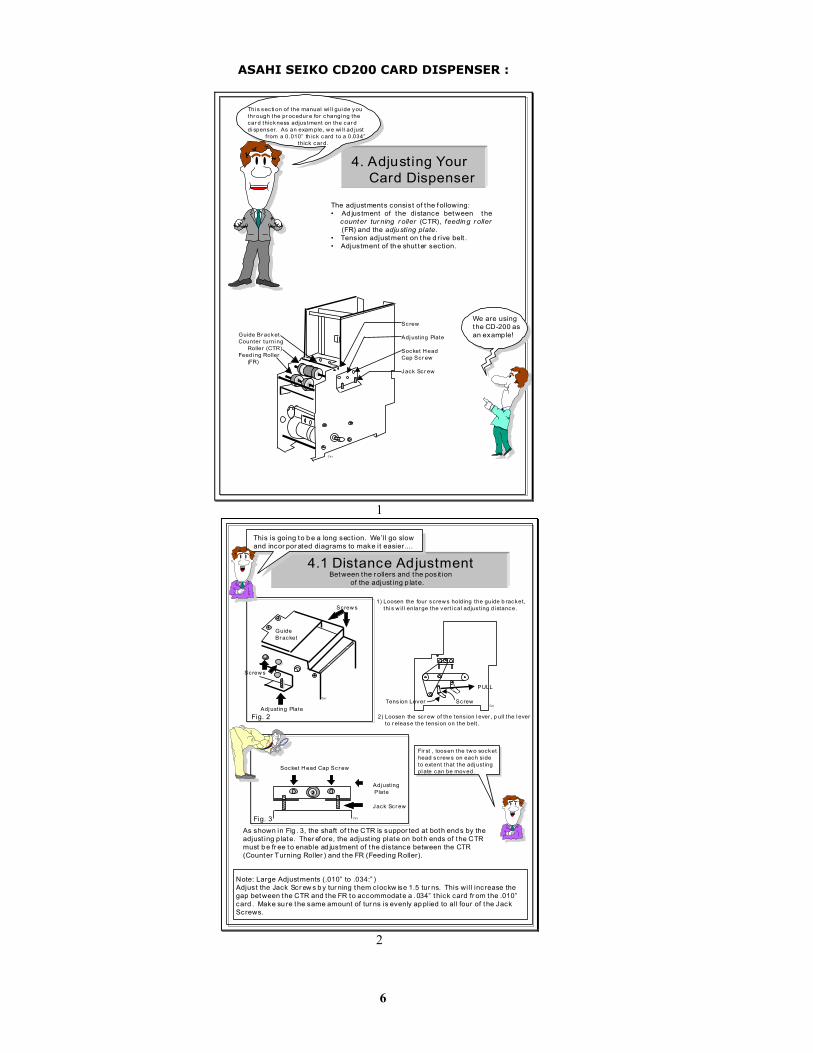
ASAHI SEIKO CD200 CARD DISPENSER :
The adjustments consist of t he following:• Ad justment of the distance between the counter tur ning r oller (CTR), feedin g r oller (FR) and the adju sting plate.• Tension adjustment on the d rive belt .• Adjustment of th e shut ter section.
We are usingthe CD-200 asan examp le!
Sc rew
Adj usting Plate
Socket H eadCap Scr ew
Jack Scr ew
Guide Br acketCounter turni ng Roller (CTR)Feedi ng Roller (FR)
Ter i
Thi s sec ti on of the manual wi ll gui de youthr ough the pr ocedur e for changi ng the car d thickness adjus tment on the car d di spenser. As an exam ple, w e wi ll ad just from a 0.010” th ick card to a 0.034” thick car d.
4. Adjusting Your Card Dispenser
1
This is going to b e a long sect ion. We’ll go slowand incor por ated diagrams to make it easier....
Fig. 2
1) Loosen the four sc rew s holding the guide b racket , thi s w il l enlar ge the vert i cal adjus t ing d istance.
Fig. 3
Adj ust ing Plate
As shown in Fig . 3, the shaft of the CTR is suppor ted at both end s by theadjust ing p late. Ther efore, the adjust ing plate on both ends of the CTRmust b e fr ee to enable ad justment of the distance between the CTR(Counter Turning Roller ) and the FR (Feeding Roller).
Socket H ead Cap Scr ew
Adj ust ing Plate
Screw s
4.1 Distance Adjustment
Jack Scr ew
Between the r ollers and the posit ion of the adjust ing p late.
Screw s
GuideBr acket
Tens ion Lever Screw
2) Loosen the sc r ew of the tens ion l ever , p ull the l ever to r elease the tensi on on the belt .
PULL
Fir st , loosen the tw o socket head sc rew s on each si deto extent that the adj ust ingpl ate can be moved.
Note: Large Adjustments (.010” to .034:” )Adjust the Jack Scr ew s b y tur ning them clockw ise 1.5 tur ns. This will increase the gap between the CTR and the FR to accommodate a .034” t hick card fr om the .010” card . Make su re the same amount of tur ns is evenly applied to all four of t he JackScrews.
Ter i
T er i
Ter i
2

7
When you ar e look ing at the car d dispenserstr aig ht on, you w ill see the m otor and ab ovethat the roll ers . Ri ght her e (w hen the shutteris li f ted ) you w ill see the car d passagebetw een the CT R and the FR. These rol ler sar e adjus ted to accomm odate a thicker card .
Fig . 4
Feedi ng Roller (FR) Assem bly
Counter Tur ning Rol lerGuide Br acket Teeth
FIGU RE 4
.045” - .060”
Car d Thi ckness
Proper Di stanceBetw een CTR & FR
.010”
.020”
.030”
.034”
.014” to .016”
.025” to .031”
.040” to .050”
.045” to .060”
Proper di stance dep ending up on card thi ckness
Fig . 5
Ter i
(Dis tance betw eenthe CTR and the FR.)
For easy vi ewi ng of the hole, rem ovethe shutter s suppor t bar and p ull theshutter UP...
Thi s is the sup por t bar. . .
TH ECARD
NOTE: Ideal ly the g ap dis tance betw een the CTR and the FR is 1.5 t i me the car d thickness !
NOTE: Make sure the card s li ding thr ough is notbei ng res tri c ted by the guide bracket teeth. When adjus t ing to a car d thi ckness (.010” to .034”, a significant change) - adjus tmentsw ill have to b e made to the CT R as w ell as thegui de br acket.
Teri
3
CARD
Pu shDown
Pu shDown
FR FRAdj ust ingPlate
CTRDO A QU IC K CHECK!By insert ing a car d and sl idi ng it throughthe rol ler s, make sur e to appl y pr essureand hold d own both s ides of the adj ust ingpl ate w i th your hands. The car d shouldsl ide thr ough wi thout i nter fer ing w ith theCTR. Double check by stack ing tw o car dstogether and go thr ough the samepr ocess . The total thickness of thecomb ined cards SHOULD be thick enoughto i nter fer e w ith the C TR. Ther efore, theCTR w il l be ab le to push the second cardback into the cartr idg e and avoid doubledi spens ing.
After pr oper gap adjus tment has beenachieved, the CTR ca n be locked into it ’ spos it ion b y t i ghtening the socket head capscr ew s on both si des of the uni t.Remi nder : Make sur e to apply and keeppr essure dow n on both sid es of theadj ust ing plate w ith your hands dur ing thispr ocess .
Nex t , m ake pr oper adjus tments to thegui de br acket . To make the adjus tmentsali gn the Guide Br acket Teeth the samegap di stance as the CTR. Both the CTRand the Guide Br acket Teeth shoul d havethe sam e gap d istance fr om the FR.
Socket H ead Scr ews
FR
CTR
.051”
Guide Bracket Teeth
Ter i
Ter i
4

8
Guide Br acketCounter turni ng Roller (CTR)Feedi ng Roller (FR)
Then car efully t ighten the Guide B racket scr ew s on both si des.
NOTE: The Gui de Br acket has a tendency to move whi le t ig hteni ngthe four sc r ews . Pl ease inser t a card for f inal visual inspec tion.
The GuideBr acket Scr ews !
Ter i
5
4.2 Belt Tension Adjustment
4.3 Shutter Adjustment While l if t ing the shut ter, insert the new car d. Then adj ust the hei ght of the pin w ith thescr ew s at b oth ends of the p in to deter mine the prop er hei ght .
Shutter
~CARD~
Fig . 7
Pin
Shutter
Sc rew
PinSc rew ~CARD~
Car dThi ckness+ 0.2mm
DispensedCar d
Tens ion Lever
Push to t ig hten. ...
Push the tensi on lever b ack to i ts pos it ion. Tig hten the tension on the beltby lock ing the p osit i on of the tension l ever w ith the screw . For the b est oper at ion, thebel ts def lec t i on should be betw een 1.5 to2mm w hen pushi ng it at the p oint show n in f i gure 6.
Fig ure 6
Final Check :
Run about 50 car ds throug h the unit to
make sure the p rop er ad justm ents have
been m ade.
Ter i
Ter i
T er i
6

9
MAINTENANCE
5. Maintenance
Thi s is the ins trum ent you w il l be us ing w hen you c lean your card dispenser . Yes, it i s a cot ton swab ! This nifty l it t le invention l et’ s you get i nto those t ight l it t le pl aces and c l ean to your heart ’ s content.
I can’t b elieve he forgot thecloth... . .. You will be needinga small piece of cloth to wipeoff the opto-sensor once every two months
The Base Plate
Insid e Wall
Roll ersUp per & Low er
Dip the cot ton sw ab in to rubb ing alcohol and c lean the roll ers as they ar e turni ng. Wipe d own the i nsi de w alls and base plate w ith a p iece of c loth di pped and w rung out(not sop ping w et).
VIEW OF T HE DISPENSER WITH T HESHUTTER REMOVED...LOOKINGDOWN FROM THE TOP... . .. .. . .. .. . ..
Fig . 9
Ideally , maintenance should b e perfor med after every 10,000 ca rds have d isp ensed....
Teri
1
Thi s is the c lutch r oller , w ear e look ing d own i nsi de the di spenser, w here the cards are s tacked!
Dispens ing Car d
Rubbing Alcohol
Now you w ill want to c l ean the c lutch r oller . This r oller tur ns fr eely. Cl ean it thoroug hly. And let thealcohol dr y befor e res tock ing the di spenser wi th car ds.
Fig . 10
Rain d rops ar e fall ing on m y head... .
Ter i
2

10
COINCO MAG50BABVALIDATOR
SECTION PAGE
Removing the Bill Box 11
Clearing a bill jam 11
Setting the bill types accepted 12-13
Cleaning the sensors 13-14
Cleaning a salted unit 14
Replacing the belts 15

11
Removing the bill box.To remove the 1000 bill stacker from the CoinCo validator follow the picture below.
REMOVING A BILL JAM
From time to time a foreign object or ripped bill will become caught in the validator. Follow thepicture below to remove the item.

12
SETTING THE BILL ACCEPT DIP SWITCHES

13
CLEANING THE BILL VALIDATOR
Refer to the pictures and the procedure on the next page to clean the bill validator every 4-6months.

14
MAGPRO CLEANING: IF ANY OF THESE PROCEDURES ARE PERFORMED TO YOUR VALIDATOR AFTER IT ISRETURNED UNDER A WARRANTY REPLACEMENT, YOU WILL BE SUBJECTED TO A $65.00 LABOR FEE.
CLEANING AND MAINTENANCE:Note: Petroleum-based cleaners and freon-based propellants can damage plastic and some electronic components.Scouring pads and stiff brushes may harm the protective conformal coating on the circuit boards and can mar theplastic. These items should never be used when cleaning the MAGPRO bill acceptor.
The MAGPRO should be cleaned every 7,000 billsor every 4 -6 months (or as needed, dependingon the environmental conditions of thelocation). Dust can be removed with a softbrush or cloth or it can be blown out usingcompressed air.Procedure:1. Disconnect power from the bill acceptor.2. Remove the bill box and use a soft cloth to wipethe dust from around the intermediate frame andstacker plate.3. Remove the lower track.4. Using compressed air or a soft brush, blow orbrush the dust off of the optic sensors and out of therecessed sensor openings.5. Remove dust from around the belts and wheels onthe lower housing and the sensors on the uppersensor board. The upper sensors are located directlyabove the lower housing sensor when the lowerhousing is installed.6. The bill path can be cleaned to remove further dirtand oil using a soft cloth moistened with a mild soapand water solution.7. Clean the magnetic head using a swab andisopropyl alcohol.8. Once the lower housing is dry, place it back intothe mainframe so that the tab on the bottom locksinto place.9. Blow the dust out of the encoder wheel and itssensors. (It may be necessary to extend the stackerplate to access the encoder wheel. Supplying powerto the unit momentarily can do this, so that thestacker plate extends.)10. Remove dust from the transport belt areas andfrom any other places of build up.11. Remount the bill box.12. Apply power and insert bills to verify that the unitis functions property.
MAGPRO CLEANING PROCEDURE FOR SALTWATER POLLUTED UNITS:Note: Petroleum-based cleaners and freon-basedpropellants can damage plastic and some electroniccomponents. Scouring pads and stiff brushes mayharm the protective conformal coating on the circuitboards and can mar the plastic. These items shouldnever be used when cleaning the BA30 bill acceptor.Procedure:1. Remove power from the bill acceptor.2. Remove the bill acceptor from the vending
machine.3. Open the bill box lid and verify that the stacker
plate is in the stand-by/home position. If it is notin the home position, apply power and observethat the stacker plate returns home.
Warning: If moisture is present, allow the unit to drythoroughly before applying power to avoid possibleshock hazard. If the stacker plate does not return tothe home position, remove power and carefullyremove the bill box to avoid damaging the bill boxand/or stacker plate.
4. Remove the lower housing.5. Remove the bottom cover from the lower
housing.6. Run hot water (1101/4-1401/4F) over the lower
housing from the top and bottom. Using a softbrush, gently clean any residual salt. Use a softabsorbent cloth to clean any residue off the lowerhousing. If the transformer gets wet, allow theunit to dry for 24 hours before applying power.
7. Remove the front mask. Using hot water and asoft brush, clean the front mask, upper sensorboard, main frame anti-pullback levers andposition sensor mount.
Caution: The motors are not protected from water,therefore the unit must be held in a manner thatprevents water from running over the intermediateframe crossbar.8. Remove the position sensor cover on the crossbarand carefully lift the LED from its mount. (Earlymodels only.)Caution: Protective coating on the LED leads shouldnot be damaged. Clean all salt residue from themount, sensor hole and detector area.The detector can be seen through the sensor hole,and is located in the chassis. Replace the positionsensor cover. (Early models only.)9. Verify that the anti-pullback levers move freely
and that the spring returns them to their openposition.
10. Allow the unit to dry thoroughly.11. Clean the magnetic head using a swab and
isopropyl alcohol.12. Replace the front mask13. Replace the lower housing cover.14. Replace the lower housing into the main frame.15. Remount the bill box.16. Apply power and insert bills to verify that the unit
is functioning properly.6 OR 7 ERROR CODE FLASHESThe cleaning procedure for this common occurrence islisted below. Just follow these steps. 1. If this code has occurred on a new machine or
one that the validators DIP switches were justchanged, Ensure that all the white plugs on theside of the validator board away from the red LEDare plugged in securely.
2. Remove the bill box.3. Turn the Changer ON then OFF in an attempt to
stop the metal push plate so that it COASTS intothe fully outward position.
4. Using an air compressor or a can of compressedair blow out the area behind the push plate untilit is completely free of all dust and lint.
5. Turn the changer power back on so that the pushplate returns to the inward position. If the sameerror code persists, repeat steps 1 - 3concentrating on the top center area behind theplate.
6. Replace the bill box.

15
REPLACING THE BELTS
Every 2-3 years the belts on the CoinCo will wear out. To replace them, remove the validatorcomponents down to the picture show. Refer to the parts diagram at the end of the manual forhelp getting to this point.

16
NOTE: Before starting this procedure ensure the phone card machine is plugged in, the ON/OFF switch is on, the carddispenser is full of cards, and all wire harnesses are connected securely and correctly.
The wires exiting the red connectors should point away from the board!
Start Here!
For more detailed trouble shooting information proceed to the next section!FOR TECHNICAL SERVICE OR TO OBTAIN A RETURN AUTHORIZATION
NUMBER CALL (888) 741-9840
ANY REPAIR RETURNED WITHOUT A RETURN AUTH. # WILL BE REFUSED!
The main logic board is reading acard dispenser hard fault or a “No
card dispenser found” fault.1. Ensure the card dispenser is
plugged in firmly in the back tothe card dispenser plate.
2. Someone has jammed a foreignobject into the output optic fromthe front card slot of themachine.
3. Replace the card dispenser.4. Replace the card dispenser
harness.5. Replace the main logic board.
NO
Does the meter onthe Main Logic
Board count up?
1. Replace the dollar bill acceptor.2. Replace the dollar bill acceptor wire
harness.(Check the yellow & blue wires)
The validator logicboard is flashing
an error code.Refer to pg. 6 forcode definitions.
YES
Refer to page 7and clean the
validator.
The main logic board is readinga low coin indication.
1. Make sure the card dispenseris plugged securely into itsconnector.
2. Ensure the low card switchhas not lost its activatinglever.
3. Replace the card dispenser.4. Replace the card dispenser
harness.5. Replace the main logic
board.
The main logic board is receivingthe bill pulses but the card
dispenser is not receiving the payout pulses.
1. Ensure the dispenser harness isplugged in firmly in the back tothe card dispenser.
2. The card dispenser is jammed.Refer to pg. 5 to repair the carddispenser.
3. The card dispenser harnessconnector is faulty.
4. Replace the card dispenser.5. Replace the card dispenser
harness.
Is the upper“Empty” LED on
the front of themachine lit?
The 2-1/2 amp fuseis blown.
If fuse blows againreplace the Main
Logic board.
NOYES
Will the validator try topull in a bill then reject it?
NO
YES
Is the green LED liton the main logic
board?
NO
Is the light up display onthe main logic board on
YESYES
YES
NO
NO
YES
Will the validatoraccept a bill and stack
it in the bill box?
TECHNICAL FLOW DIAGRAM FOR THE AC502 SERIES

17
Problem:
A. The phone cardmachine is completelydead. (The green LED onthe main logic board is notlit.)
B. The “Empty LED is lit.
C. The green LED on themain logic board is lit butthe light up display neverlights.
D. The dollar bill acceptoraccepts and stacks themoney but the bill meternever counts up.
F. The dollar bill acceptorstacks the bills, the metercounts up, but the carddispenser does not payout.
G. Bill Validator will not pullin the bill and the “Empty”LED is not lit.
Solution:
1. Ensure the phone card machine is plugged in.2. Ensure the on/off switch is rocked to the (1) position
(down).3. Unplug the female end of the line cord from the main
logic board AC connector and plug it in again tightly.4. Measure the AC voltage at the outlet or check the
breaker/fuse box. You can also plug another item intothe AC wall outlet to ensure there is power present atthe outlet.
5. Inspect the AC line cord for cuts or abrasions.6. Check both fuses on the Main Logic Board.7. Replace the main logic board.8. Replace the line cord.
1. Ensure the card dispenser is not out of cards. 2. Check the card dispenser wire harness that extends
from the back of the card dispenser to ensure it isplugged in firmly.
3. Check the card output slot for foreign material.4. Replace the card dispenser.5. Replace the card dispenser wire harness.
1. Bad 5 or 12vdc regulator on the main logic board.2. The card dispenser is shorted.3. Replace main logic board.4. Replace card dispenser.
1. Check continuity and for pin damage to the blue andyellow wires on the validator harness.
2. Replace the validator wire harness.3. Replace the validator.
1. Ensure the dip switch settings are still correct. 2. Check the continuity of the brown and purple wires on
the card dispenser wire harness.3. The card dispenser is jammed. Go to pg. 6. To un-
jam the card dispenser.4. Replace the card dispenser wire harness.
1. Ensure that the red Validator status LED is on steady.2. Check for blockage in the front of the bill Validator by
removing the lower housing.3. Check for customer screwdriver prying or pocket knife
gouges in the plastic which may cause the bill to stopand not go in. If you find some, use emery cloth andsand them down until smooth again.
4. Replace Bill Validator.
TROUBLESHOOTING GUIDETO USE THE TROUBLESHOOTING GUIDE, MATCH UP THE PROBLEM, THEN FOLLOW THE
SOLUTION SUGGESTIONS. After every step re-try operating the changer to see if the problem has beensolved.

18
PROBLEM:
H. The dollar bill acceptorpulls in the bill slightlythen rejects it.
I. The dollar bill acceptor
red status LED flashesa “5” error code.
J. The dollar bill acceptorred status LED flashesa “6 or 7” error code.
K. The dollar bill
acceptors red statusLED is on steady but itstill will not accept thebill.
L. The red “empty” LED
on the outside of thephone card machine ison, the red status LEDon the main logicboard is flickering onand off normally, andthe card dispenser isfull of cards.
FOR TECHNICALSERVICE OR TO
OBTAIN A RETURNAUTHORIZATION
NUMBER CALL (888) 741-9840
SOLUTION:
1. Clean the validator. (pg. 14)2. Remove the lower housing (pg. 11) of the dollar bill
acceptor. Ensure the center wheel spins freely. Pushstraight down on it slightly to loosen.
1. Clean the validator optic LED’s. (See pg. 13-14)2. Ensure that all the wire harness plugs are plugged firmly
into their white female sockets.3. Turn to the back page of this manual and check for a
Coin Acceptors branch in your area to repair your dollarbill acceptor.
1. Take the bill stacker off the dollar bill acceptor. Cyclethe power on / off using the switch on the main logicboard and coast the silver push bar so that it stops in itsfully extended position. Blow out the area behind thepush bar with high pressure or canned air. Concentrateon the encoder wheel in the area top center behind thepush bar.
2. Turn to the back page of this manual and check for aCoin Acceptors branch in your area to repair your dollarbill acceptor.
1. Pull out the lower housing, see page 8, and look forsomething obstructing the bill path. (I.e. gum; papertickets, cards, etc.)
2. Look inside the Plexiglas case on the side of the dollarbill acceptor. Ensure that all the wire harness plugs areplugged firmly into their white female sockets.
1. Ensure the card dispenser is not out of cards. 2. Check the card dispenser wire harness that extends
from the back of the card, ensure it is plugged in firmly.3. Ensure the silver armature lever below the cards has
not broken off.4. Replace the card dispenser.5. Replace the card dispenser wire harness.
ANY REPAIR RETURNED WITHOUT ARETURN AUTH. # WILL BE REFUSED!
TROUBLESHOOTING GUIDETO USE THE TROUBLESHOOTING GUIDE, MATCH UP THE PROBLEM, THEN FOLLOW THE
SOLUTION SUGGESTIONS. After every step re-try operating the changer to see if the problem has beensolved.
19
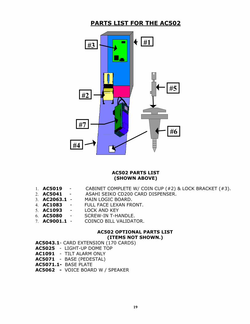
PARTS LIST FOR THE AC502
AC502 PARTS LIST(SHOWN ABOVE)
1. AC5019 - CABINET COMPLETE W/ COIN CUP (#2) & LOCK BRACKET (#3).2. AC5041 - ASAHI SEIKO CD200 CARD DISPENSER.3. AC2063.1 - MAIN LOGIC BOARD.4. AC1083 - FULL FACE LEXAN FRONT.5. AC1093 - LOCK AND KEY6. AC5080 - SCREW-IN T-HANDLE.7. AC9001.1 - COINCO BILL VALIDATOR.
AC502 OPTIONAL PARTS LIST(ITEMS NOT SHOWN.)
AC5043.1- CARD EXTENSION (170 CARDS)AC5025 - LIGHT-UP DOME TOPAC1091 - TILT ALARM ONLYAC5071 - BASE (PEDESTAL) AC5071.1- BASE PLATEAC5062 - VOICE BOARD W / SPEAKER
#5
#6
#1#3
#4
#2
#7

20
COINCO PARTS LIST
MOUNTING ASSEMBLY PARTS BREAKDOWN
PICTURE ##1#2#3#4#5#6#7
PART #MP90-1-1MP91-1-2MP90-1-3MP90-1-4MP91-1-5MP90-1-6MP91-1-7
DESCRIPTIONMachine Screw“Snack Mask” Black PlasticMachine ScrewMain Frame, PlasticMask Gold Mounting BracketBill grounding springMachine Nut

21
COINCO PARTS BREAKDOWN
PICTURE ##1#2#3#4#5#6#7#8#9#10#10#11#12#13#14#15#16
PART #MP90-2-1MP90-2-2MP90-2-3MP90-2-4MP91-2-5MP90-2-6MP90-2-7MP90-2-8MP90-2-9MP90-2-10MP91-2-10MP90-1-11MP90-2-12MP90-2-13MP90-2-14MP91-2-15MP91-2-16
DESCRIPTIONBottom Lower Housing CoverTransformer holding hose120VAC TransformerLower Spring, Anti-Cheat LeverLower Mounting, Anti-Cheat LeverLower Anti-Cheat LeverLower Housing Assembly, CompleteBelt, CenterLower Anti-Cheat Assembly, CompletePlastic Wheels & Rubber BeltsRubber Belts ONLY (Each)Shaft, DriveSpring, MAGScrew, #4, PlasticRoller, IdlerSensor Board, LowerPulley & Hub Assembly, Complete
BELTSONLY!
MP91-2-10
22
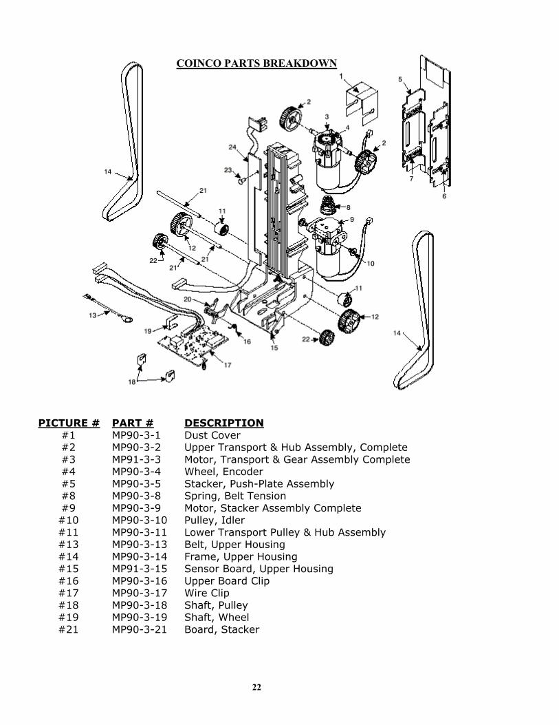
COINCO PARTS BREAKDOWN
PICTURE ##1#2#3#4#5#8#9#10#11#13#14#15#16#17#18#19#21
PART #MP90-3-1MP90-3-2MP91-3-3MP90-3-4MP90-3-5MP90-3-8MP90-3-9MP90-3-10MP90-3-11MP90-3-13MP90-3-14MP91-3-15MP90-3-16MP90-3-17MP90-3-18MP90-3-19MP90-3-21
DESCRIPTIONDust CoverUpper Transport & Hub Assembly, CompleteMotor, Transport & Gear Assembly CompleteWheel, EncoderStacker, Push-Plate AssemblySpring, Belt TensionMotor, Stacker Assembly CompletePulley, IdlerLower Transport Pulley & Hub AssemblyBelt, Upper HousingFrame, Upper HousingSensor Board, Upper HousingUpper Board ClipWire ClipShaft, PulleyShaft, WheelBoard, Stacker

23
MP90-4-IF
3
4
COINCO PARTS BREAKDOWN
PICTURE ##1#2#3#4#5
PART #MP90-4-1MP91-4-2MP90-4-3MP90-4-4MP90-4-IF
DESCRIPTIONLid, Logic board BoxBody, Logic board BoxMain Logic BoardSticker, Serial Number / WarrantyIntermediate Frame with Bearings

24
8. PARTS LISTING
No. Parts Descrip tion Part Number 1 Side Plate (L) Assembly 2 Screw, M2.6 x 6 3 Screw, M3 x 5 4 Flange Bushing 5 E ring #4 6 Screw, M3 x 5 SHCS 7 Adjusting Plate 8 Screw, M3 x 6 (Set) 9 Screw, M3 x 6 10 Collar, 3 x 4 x 2.5 11 Chain Assembly 12 Weight 13 Screw, M3 x 3 14 Lock Plate Spring15 Stopper Plate16 Clutch Shaft17 Screw, M2.6 x 418 Spring Plate19 Clutch Spring20 Clutch Pin21 Clutch Roller22 Return Spring23 Driving Cam24 Driving Pin25 Screw, M3 x 826 Washer, 3 x 8 x 0.827 Guide Bracket28 Guide29 Spring Pin, 1.5 x 1030 Counter Turning Roller Assy31 Discharge Roller Assy32 Discharge Idle Guide33 Shutter
When ord ering a par t rememberto use the par tnumber ....
34 Shutter Guide Shaft35 Base Plate36 Geared Motor
CDS204P010001S2606RHSFS3005RHSFCDS204P010005W4000ER99S3005HH99CDS204P010038S3006SS99S3006RHSFCDS204P010003CDS204P010004CDS204P010045S3003RHSFCDS204P010006CDS204P010015CDS204P010016S2604RHSWCDS204P010017CDS204P010018CDS204P010019CDS204P010020CDS204P010021CDS204P010022CDS204P010023S3008RHSFW3008FW08CDS204P010014CDS204P010026CDS204P010013CDS204P010025CDS204P010024CDS204P010011CDS204P010007CDS204P010010CDS204P010035CDS204P010029
Item
No. Parts Descrip tion Part Number
8. PARTS LISTING
37 Sensor Bracket38 Photo (Opto) Sensor39 Discharge Roller40 Discharge Roller Shaft 41 Screw, M3 x 4 (Set)42 Feeding Roller Assy. 43 Shut-off Lever44 Sensor Spring45 Shut-off Lever Weight46 Support Bar47 E Ring #2.548 Tension Roller49 Tension Lever50 Tension Lever51 MXL Geared Pulley (Z = 26)52 MXL Geared Pulley (Z = 30)53 MXL Geared Pulley (Z = 32)54 MXL Geared Pulley (Z = 18) 55 MXL Geared Belt (Z = 87)56 MXL Geared Belt (Z = 95)57 E Ring #2 58 Side Plate (R) Assy. 59 Sensor Lever Weight60 Screw, M3 x 561 Empty Sensor Lever62 Spring Pin, 2.5 x 863 DC Solenoid, 24 VDC/12VDC64 Clutch Lever65 Nut, M366 Solenoid Bracket67 Control Board Insulator68 (CD-9603) Control Board (CD-200) (CD-9603) Control Board (CD-1000)
(CD-9102) Control Board (CD-200,24V)
(CD-9102) Control Board(CD-1000,24V)
(CD-9102) Control Board (CD-200,12v)
(CD-9102) Control Board (CD-1000-12/v)
CDS204P010028CDS204P010027CDS204P010039CDS204P010040S3004S99CDS204P010042CDS204P010030CDS204P010031CDS204P010032CDS204P010046W2500ER99CDS204P010048CDS204P010049CDS204P010047CDS204P010051CDS204P010052CDS204P010053CDS204P010050CDS214P010034CDS104P010041W2000ER99CDS204P010002CDS204P010059S3005RHSFCDS204P010061CDS204P010062CDS204P010063CDS204P010064N3000HX99CDS204P010066CDS204P010067CDS204P010603CDS104P010603CDS204P010625CDS104P010625CDS203P010625CDS203P010625
Item
Remem ber .. . ..Thi s is the numb erthat you w ant to use w hen or der ing par ts!

25
Arizona3226 S. Fair LaneTempe, AZ 85282Phone: 602-431-0632Chris Mattingly
California11618 E. Washington Blvd.Suite # JWhittier, CA 90606Phone: 562-692-3059
FLORIDATampa6704 Benjamin RoadSuite 200Tampa, FL 33634Phone: 813-249-7338Bob Wilcox
Ft. LauderdaleAmerican Changer1400 NW 65th PlaceFt. Lauderdale, FL 33309888-741-9840RMA# Needed
Georgia4215 Wendall Dr SWSuite # EAtlanta, GA 30336Phone: 404-691-2777Chuck Crockett
Illinois862 Eagle Dr.Bensenville, IL 60106Phone: 630-860-2650Mike Durec
Louisiana524 Elmwood PkwySuite 190Harahan, LA 70123Phone: 504-734-0280Frank Case
Maryland6655 Amberton DriveBay “L”Baltimore, MD 21227Phone: 410-379-2680Bill LeJune
Massachusetts60 Prospect StreetWaltham, MA 02453Phone: 781-894-4525Kevin Cole
Missouri1236 Dielman Industrial CTSt Louis, MO 63132Phone: 314-725-0100Charlie Pavia
Ohio225 Corporate CourtSuite IFairfield, OH 45014Phone: 513-874-4460Joe Steddom
TEXASDallas3031 Quebec StreetSuite 115Dallas, TX 75247Phone: 214-638-3970
Houston2500 Central ParkwaySuite “K”Houston, TX 77092Phone: 713-683-6558Steve TenBarge
Washington1020 Industrial DriveBldg. 32Seattle, WA 98188Phone: 206-575-1999Carl Goodson