Embed Size (px)
Citation preview
Technical University Berlin
Telecommunication Networks Group
Double Hopping:A new Approach for Dynamic FrequencyHopping in Cognitive Radio Networks
Daniel Willkomm, Mathias Bohge, DanielHollos, and James Gross
{willkomm,bohge,hollos,gross}@tkn.tu-berlin.de
Berlin, January 2008
TKN Technical Report TKN-08-001
TKN Technical Reports Series
Editor: Prof. Dr.-Ing. Adam Wolisz

Abstract
One of the major challenges in designing cellular Cognitive Radio (CR) networks is theavoidance of Secondary User (SU) interference to so called Primary Users (PUs) operatingin the licensed bands. Usually, SU operation has to be interrupted periodically in orderto detect PU activity and avoid the respective frequencies. Recently, Dynamic Frequen-cy Hopping (DFH) mechanisms have been suggested to enable reliable PU detection andcontinuous SU operation at the same time. Applying DFH in a multi-cell environment addsthe challenge of mitigating Co-Channel Interference (CCI). In this context, graph coloringbased optimization, which previously solely has been applied to non-hopping networks, is usedto develop sophisticated centralized as well as distributed DFH methods. In this paper, weintroduce a new DFH approach to allow reliable PU detection and continuous SU operationin cellular CR networks: Double Hopping (DH). We present a centralized optimal, as wella distributed version of DH and evaluate their performance in terms of frequency usage. Weshow that the performance of the sub-optimal distributed version is only slightly worse thanthe optimal performance, and, thus, outperforms existing distributed approaches by far.
TU Berlin
Contents
1 Introduction 2
2 Related Work 42.1 Frequency hopping . . . . . . . . . . . . . . . . . . . . . . . . . . . . . . . . . 42.2 Frequency hopping in CR networks . . . . . . . . . . . . . . . . . . . . . . . . 52.3 Graph coloring . . . . . . . . . . . . . . . . . . . . . . . . . . . . . . . . . . . 6
3 Double Hopping 73.1 System model . . . . . . . . . . . . . . . . . . . . . . . . . . . . . . . . . . . . 73.2 Double Hopping operation . . . . . . . . . . . . . . . . . . . . . . . . . . . . 83.3 Differences between Double Hopping and Revolver Hopping . . . . . . . . . 9
4 Hopping Pattern Generation 114.1 Simulation model . . . . . . . . . . . . . . . . . . . . . . . . . . . . . . . . . . 114.2 Optimal Frequency Allocation . . . . . . . . . . . . . . . . . . . . . . . . . . 124.3 Distributed Frequency Allocation . . . . . . . . . . . . . . . . . . . . . . . . 14
5 Performance Analysis 165.1 Methodology . . . . . . . . . . . . . . . . . . . . . . . . . . . . . . . . . . . . 165.2 Optimal initialization results . . . . . . . . . . . . . . . . . . . . . . . . . . . 175.3 Random initialization results . . . . . . . . . . . . . . . . . . . . . . . . . . . 17
6 Conclusions 22
A Distributed DFH Protocol 23A.1 Message types and timer . . . . . . . . . . . . . . . . . . . . . . . . . . . . . . 23A.2 initialization state . . . . . . . . . . . . . . . . . . . . . . . . . . . . . . . 24A.3 startHopping / startNonHopping state . . . . . . . . . . . . . . . . . . . . . 26A.4 hopping state . . . . . . . . . . . . . . . . . . . . . . . . . . . . . . . . . . . . 29A.5 stopHopping state . . . . . . . . . . . . . . . . . . . . . . . . . . . . . . . . . 32A.6 nonHopping state . . . . . . . . . . . . . . . . . . . . . . . . . . . . . . . . . . 32A.7 Time synchronization . . . . . . . . . . . . . . . . . . . . . . . . . . . . . . . 35
B Acronyms 36
References 39
Copyright at Technical UniversityBerlin. All Rights reserved.
TKN-08-001 Page 1
TU Berlin
Chapter 1
Introduction
Cognitive Radio (CR) has become a popular and promising approach to overcome the artifi-cial spectrum scarcity. The key idea of CR technologies is to allow the usage of temporarilyunused licensed spectrum by so called Secondary Users (SUs) under the constraint that thespectrum has to be vacated, as soon as the owner of the band – referred to as PrimaryUser (PU) – returns. To meet this constraint, the spectrum has to be sensed periodically –at least very tmax – in order to detect potentially appearing PUs. In order to perform reliablesensing on a frequency, data transmission has to be interrupted. Depending on the PU detec-tion requirements and the sensitivity of the sensing antenna, the sensing process can requireup to hundreds of milliseconds. Obviously, such interruptions in data transmission severelydegrade the Quality of Service (QoS) – especially for real-time or streaming applications.
To avoid periodic interruptions of the payload communication, Dynamic Frequency Hop-ping (DFH) has been proposed for cellular CR networks [1, 2]. The basic idea of DFH is thefollowing: A cell performs sensing on frequency Y in parallel to data transmission on fre-quency X. After tmax, the cell hops to frequency Y and performs sensing on frequency X andso on. Obviously, an additional frequency per cell is needed to realize this approach. Hav-ing a whole network of mutually interfering cells, mitigating Co-Channel Interference (CCI)becomes crucial. The frequency usage of interfering cells has to be coordinated to avoid col-lisions. By using a smart distribution of frequencies among the cells in the network, the totalnumber of additional frequencies in use can be minimized in order to maximize the number ofsupportable cells. Additionally, reducing the number of frequencies used for secondary com-munication also reduces the probability of interference with PUs. Whenever a PU appearson a frequency that is currently used for secondary communication, the secondary systemtemporarily produces potentially harmful interference to the licensed PU communication.Reducing the number of frequencies used for secondary communication, thus, also reducesthe probability of interference with primary communications.
In non-hopping networks, frequency planning, which is based on solving the FrequencyAssignment Problem (FAP) [3], is an important method to control CCI in multi-cell com-munication systems. A typical FAP scenario consists of a set of cells. Each cell has a certainbandwidth requirement that needs to be complied by assigning a sufficient amount of fre-quencies to it. Interfering cells should not be assigned the same frequencies for operation.Solving the FAP results in a system-wide frequency setting that fulfills all bandwidth require-ments at a minimum total amount of assigned frequencies. Mathematically, the FAP can be
Copyright at Technical UniversityBerlin. All Rights reserved.
TKN-08-001 Page 2
TU Berlin
expressed as a graph coloring problem: the nodes represent the cells, and the edges betweenthe nodes represent their interference relationships. Each node is assigned one (or multiple)color(s) such that two connected nodes never own the same colors. The optimization goal isto minimize the total number of colors in use.
The above graph coloring problem is computationally complex. Mathematically speaking,it is similar to the list coloring problem, which is known to be np-complete [4]. Finding thesystem optimum for practically relevant systems requires prohibitively long computationtimes even with modern computers. Therefore two approximation approaches are usuallyapplied:
• Suboptimal centralized algorithms which have a significantly reduced computationalcomplexity while handling the full interference graph. For this approaches a singlepoint of knowledge is assumed, which usually involves a significant signalling overhead.
• Decentralized approaches, in which each node selects its frequency based only on partialknowledge of the interference graph. This allows for parallelization of the computationand leads to the most significant reduction of the computational time.
So far, frequency planning has been studied for “frequency static” cells, i.e. cells whichdo not (or very rarely) change their operating frequency over time. In such cellular networks,both above mentioned approximation approaches achieve remarkably good results in thesense of minimizing the number of frequencies necessary for assuring a given level of traffic,as compared to the real optimum. It is intuitively clear that the FAP approaches a new levelof complexity, if DFH is applied. Thus, the issue of reducing the computational complexitybecomes critical – making decentralized approaches, as described above, especially attractive.
The question investigated in this report is how to minimize the number of frequenciesrequired for DFH operation in a network of CR cells. The contributions of this report are:
• The presentation of a new concept for DFH called Double Hopping (DH).
• A Linear Integer Program (LIP) formulation for minimizing the number of frequen-cies required in DH mode. This optimum serves as a benchmark for the distributedalgorithms.
• A distributed heuristic for minimizing the number of frequencies called DistributedFrequency Allocation (DFA). DFA is based on the DH concept.
• A performance comparison of the DFA: (a) with the optimum, and (b) with theDistributed Hopping Approach (DHA), introduced in [5].
• A full protocol specification for both, the DFA and the DHA.
The remainder of this report is structured as follows. Chapter 2 presents related work onfrequency hopping and the FAP in wireless networks. The general DH approach is introducedin Chapter 3 and the centralized and distributed realizations in Chapter 4. In Chapter 5, wepresent a performance evaluation and compare the different approaches. Finally, in Chapter 6,we conclude the report.
Copyright at Technical UniversityBerlin. All Rights reserved.
TKN-08-001 Page 3

TU Berlin
Chapter 2
Related Work
In this chapter, we first summarize related work that has been done in the area frequencyhopping in general followed by CR specific frequency hopping related work. Afterwards, wepoint out related work that has been done in the area of of graph coloring for CR networks.
2.1 Frequency hopping
The idea of frequency hopping has gained attention in the context of GSM cellular systems,Bluetooth r©, Wireless Local Area Network (WLAN), and recently also in the CR community.
In the Global System for Mobile Communications (GSM) standard, frequency hoppingis an optional mode to mitigate fast fading and co-channel interference. If frequency hoppingis enabled, the tranmit frequency per terminal is changed once every Time Division MultipleAccess (TDMA) frame (which has a duration of 4.17 ms) according to a prespecified hoppingsequence. The impact of this hopping sequence (also referred to as Mobile Allocation List(MAL)) design is studied in [6]. The authors propose a scheme which generates frequencylists assuming the knowledge about the frequency lists of neighboring, i.e. interfering, BaseStations (BSs) such that interference between the neighboring (hopping) cells is within somespecified constraint. Further work on the assignment of frequency lists in GSM systems can befound in [7]. The authors extend the above work by analyzing the effect of MAL coordinationamong several cells. The paper also discusses an algorithm to modify MALs. In contrast,[8] investigates dynamic frequency hopping in GSM and compares it to random hopping.The frequency hopping pattern of a mobile is adapted based on measurements made at thebase station and the mobile. Recalculations are done after every TDMA frame, updating thehopping pattern of the mobiles. The paper studies several degrees of dynamic adaptationsfrom only exchanging the worst channel to exchanging the whole hopping pattern.. However,the paper does not consider a jointly performed frequency list assignment over several cells.
For similar reasons (i.e. mitigating interference and fading), frequency hopping is appliedin Bluetooth r© systems. Hopping is performed every 625 µs. Each bluetooth cell chooses oneout of several pre-specified pseudo-random hopping sequences. Recently, the Bluetooth Spe-cial Interest Group (SIG) adopted a non-cooperative Adaptive Frequency Hopping (AFH)method for second generation Bluetooth devices to combat the so called frequency-static in-terference that originates e.g. from WLAN systems or microwave ovens [9, 10]. AFH enables
Copyright at Technical UniversityBerlin. All Rights reserved.
TKN-08-001 Page 4
TU Berlin
Bluetooth devices to adapt to the environment by identifying fixed sources of interferenceand excluding them from the frequency hopping list (categorization in “good” and “bad”channels). This process of re-mapping also involves reducing the number of channels to beused for hopping. Regulation authorities have specified a minimum number of channels tobe used by a Bluetooth system. If the number of “good” channels is less than the specifiedminimum, additionally some “bad” channels have to be used. In [11], an interesting solutioncalled Adaptive Frequency Rolling (AFR) to combat self -interference in Bluetooth systems,i.e. interference caused by overlapping Bluetooth cells, is proposed. The authors propose todivide the 79 channels into distinct “hopsets”. A Bluetooth cell remaims in a hopset for acertain amount of time, after which it switches to the next hopset. Each cell, thus, is “rolling”through the whole spectrum. If a collision between two cells is detected (increased PacketError Rate (PER)), the cell performs a random jump. The authors extend their proposal tocombat frequency-static interference by introducing AFR with probing, where – similar toAFH – certain frequencies can be excluded from the hopset.
In [12], Mishra et al. study the impact of hopping WLANs on the fairness provided withina larger network of uncoordinated WLAN cells. The authors propose to assign a hoppingpattern to each WLAN cell such that all WLAN cells change their operation frequency aftersome transmission cycles. By this mechanism the performance degradation of interferenceis somewhat spread over all cells in the network over a longer time span, leading to anincreased system-wide cell-level fairness. Note that in WLAN systems the number of availablefrequencies is limited such that several adjacent WLAN cells will be exposed to mutualinterference.
2.2 Frequency hopping in CR networks
In contrast to the application of frequency hopping in non-CR related networks (e.g. GSM,WLAN, or Bluetooth r©), where its main function is to mitigate fading effects and balanceinterference (as described above), the scope of applying frequency hopping in CR networksis to allow continuous data transmission and at the same time assuring the unimpaired op-eration of the PU. To the best of our knowledge, so far, among existing frequency hoppingapplications solely Bluetooth r©’s AFR approach [11] is somewhat related and could be mod-ified for CR operation. AFR tries to avoid frequencies occupied by WLAN systems (whichcould be seen as PUs) and at the same time also avoids CCI between different Bluetoothsystems. However, since AFR has been developed under non-CR related assumptions, a highnumber of modifications would be necessary to support CR operation.
Frequency hopping in CR networks has been first considered within the IEEE 802.22standardization process [13]. IEEE 802.22 is an emerging standard for Wireless RegionalArea Networks (WRANs) operating on a license-exempt and non-interference basis in thespectrum allocated to TV broadcast services (between 47 − 910 MHz). It aims in providingalternative broadband wireless Internet access in rural areas without impacting the existingTV (i.e. PU) services.
Based on that standard, we have been the first ones to introduce the general concept ofDynamic Frequency Hopping (DFH) in 802.22 in [1, 2]. In these papers, we present phase-shifted operation for interference-free sensing and collision-free hopping in combination with
Copyright at Technical UniversityBerlin. All Rights reserved.
TKN-08-001 Page 5

TU Berlin
a cooperative hopping approach for neighboring cells referred to as Revolver Hopping (RH).Additionally, the concept of Dynamic Frequency Hopping Community (DFHC) is proposedas an effective way to organize the hopping of neighboring cells. Based on the RH approachpresented in [2], the Distributed Hopping Approach (DHA) is proposed in [5]. DHA is adistributed algorithm realizing RH in a cluster of IEEE 802.22 cells without the need of acentral controller managing the hopping patterns of the individual cells. However, it is alsoshown in [5] that there is a large difference in the performance of DHA and the theoreticaloptimal application of RH. This circumstance was one of the main motivations for us to searchfor a better performing distributed solution for solving the frequency assignment problem,which is done in this paper.
2.3 Graph coloring
The utilization of graph coloring in order to find optimal frequency assignments in ”frequency-static” networks is well documented in literature. Basic studies on its use in connection withcellular networks are reported in [14, 15]. For more in-depth studies, an excellent web pageon the topic is maintained by Eisenblatter and Koster [3].
In [16] and [17] two different approaches are made to use graph coloring in CR networks.However, note that in both papers, ”frequency-static” networks are considered. In [16], incontrast to our approach, each node in the graph repersents one CR terminal. Each terminalis subject to an individual PU interference. Depending on this interference, the frequenciesowned by a PU are more or less valuable for a certain terminal. When assigning the frequencyto a terminal, this relationship is recognized by different so called ”rewards” that are creditedto the terminal at the time of the assignment. In addition, power control is used to controlinterference. The objective in [16] is the maximization of the network utility subject to rewardand fairness constraints for a given number of terminals and available frequencies. Recall that,in contrast to that, our goal is to mininmize the number of necessary frequencies in order tomaximize the number of supported terminals. In [17], the maximization of the network utilityis considered as well, but, in contrast, all terminals experience the same interference fromPUs. In conformity with our approach, the total number of channels used in the network isminimized. However, since there is a differing graph coloring - network relation, and sincethe different channels can have different bandwidths, and the number of terminals is fixed, acompletely different optimization problem is formulated.
Copyright at Technical UniversityBerlin. All Rights reserved.
TKN-08-001 Page 6

TU Berlin
Chapter 3
Double Hopping
In this chapter we describe the Double Hopping (DH) approach for DFH in CR networks.After presenting the assumed system model, we introduce the general concept of DH. After-wards, we provide a brief comparison with the RH approach described in [1, 2, 5].
3.1 System model
We consider a system model based on the IEEE 802.22 standard [18]. IEEE 802.22 networksare organized in cells of several kilometers in diameter. Each cell consists of one BS and anumber of associated terminals. The BS possesses total control over all terminals in its cell.Communication is performed on TV channels that momentarily are not in use by the TVbroadcasting Primary User (PU). We refer to the selected channels as working frequencies.To select one such working frequency for communication, the BS forces the terminals to sensethe spectrum, collects the sensing results, and decides on the working frequency to be used bythe cell. In order to avoid harmful interference, the working frequency has to be periodicallysensed for (re)appearing PUs.
The maximal interference time (tmax) is the maximum time span an SU is allowed tointerfere with a PU. The data transmission time (tdata) is defined to be the maximumperiod of time a CR cell consecutively uses a working frequency for data transmission, with(tdata ≤ tmax). The sensing time (tsens) is defined as the minimum amount of time requiredto (1) perform sensing on a set of ns frequencies1 (by the BS and the terminals), (2) gatherthe sensing information at the BS, and (3) inform all terminals about the working frequencyto be used for the next data transmission period. The quiet time (tquiet) is defined to be theamount of time a frequency is not used for data communication in order to perform sensing,which obviously implies tquiet ≥ tsens. In our investigation, tquiet is the smallest time unit weconsider, i.e. time is discrete and quantized into units of tquiet. Hence, the data transmissiontime (tdata) is a multiple integer of tquiet. Nq is defined as the number of quiet times per datatransmission time (Nq = tdata/tquiet). The frame time (tframe) defines the periodic operation
1The time needed for sensing depends on the chosen sensing technique (which is beyond the scope of thispaper). Additionally, it also depends on the number of frequencies to sense. For simplicity, we assume that allfrequencies can be sensed in parallel. In real-world systems, the BS has to select a subset ns of the frequenciesto sense within the specified time interval.
Copyright at Technical UniversityBerlin. All Rights reserved.
TKN-08-001 Page 7

TU Berlin
Figure 3.1: Common Double Hopping operation
cycles and computes to tframe = tdata + tquiet.In order to perform reliable sensing, the frequency being sensed, as well as up to k
neighboring frequencies at both sides of the sensed spectrum must not be used for datatransmission. Note that - for the sake of simplicity - we assume k = 0 for our investigations.Moreover, we do not investigate specific sensing mechanisms. Consequently, the reliability ofsensing is not taken into account in our investigations.
3.2 Double Hopping operation
Double Hopping (DH) is a new approach for cooperative DFH in CR networks. DH relieson the phase shifted operation of neighboring cells as introduced in [2]. Each cell has adedicated working frequency, which is only used by that cell. Additionally, there is onesensing frequency for all cells. Once the data transmission time (tdata) of a cell expires, thecell hops to the sensing frequency, in order to perform sensing on its working frequency. Itcontinues its current communication on the sensing frequency for tquiet, before hopping backto its working frequency. Due to the time shifted operation all cells can consecutively switchto the sensing frequency in order to perform sensing on their working frequency. After onecycle, the sensing frequency has to be sensed simultaneously by all cells, i.e. all cells mustshare a common slot for sensing the sensing frequency. Consequently, each cell needs twosensing slots, one for the working frequency (Nwf) and one for the sensing frequency (Nsf).
Figure 3.1 shows an example for DH of 3 neighboring cells (i.e. all cells are mutuallyinterfering). The operation period of all cells is shifted by multiple quiet times tquiet againsteach other. During the sensing slot for the working frequency (Nwf) a cell hops to the sensingfrequency (frequency 4 in Figure 3.1) to continue data transmission and perform sensing onits working frequency. In Figure 3.1, the sensing slots for cell two are marked. Note however,that the sensing slots for the sensing frequency (Nsf) are the same for all other cells.
Due to the phase-shifted operation a maximum number of Nq neighboring cells can besupported in a DH network. In order to be able to support Nq neighboring cells, all cells haveto sense the sensing frequency in the same time slot, as shown in Figure 3.1. However, it is
Copyright at Technical UniversityBerlin. All Rights reserved.
TKN-08-001 Page 8
TU Berlin
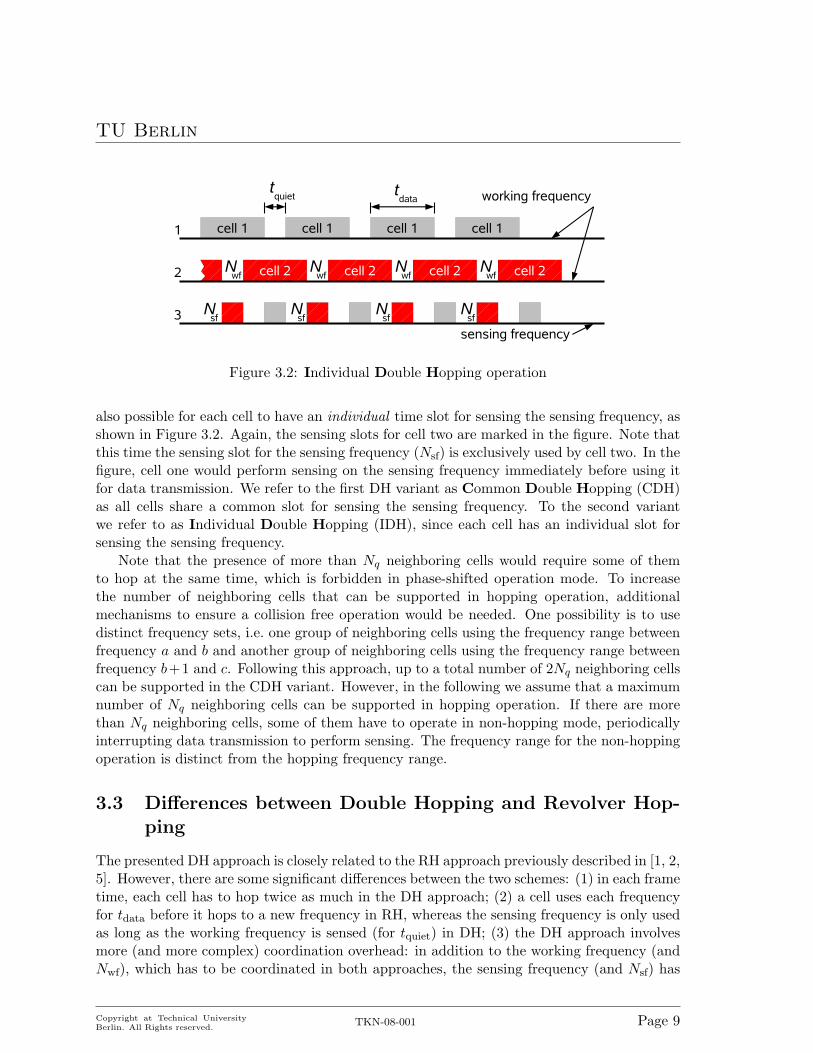
Figure 3.2: Individual Double Hopping operation
also possible for each cell to have an individual time slot for sensing the sensing frequency, asshown in Figure 3.2. Again, the sensing slots for cell two are marked in the figure. Note thatthis time the sensing slot for the sensing frequency (Nsf) is exclusively used by cell two. In thefigure, cell one would perform sensing on the sensing frequency immediately before using itfor data transmission. We refer to the first DH variant as Common Double Hopping (CDH)as all cells share a common slot for sensing the sensing frequency. To the second variantwe refer to as Individual Double Hopping (IDH), since each cell has an individual slot forsensing the sensing frequency.
Note that the presence of more than Nq neighboring cells would require some of themto hop at the same time, which is forbidden in phase-shifted operation mode. To increasethe number of neighboring cells that can be supported in hopping operation, additionalmechanisms to ensure a collision free operation would be needed. One possibility is to usedistinct frequency sets, i.e. one group of neighboring cells using the frequency range betweenfrequency a and b and another group of neighboring cells using the frequency range betweenfrequency b+1 and c. Following this approach, up to a total number of 2Nq neighboring cellscan be supported in the CDH variant. However, in the following we assume that a maximumnumber of Nq neighboring cells can be supported in hopping operation. If there are morethan Nq neighboring cells, some of them have to operate in non-hopping mode, periodicallyinterrupting data transmission to perform sensing. The frequency range for the non-hoppingoperation is distinct from the hopping frequency range.
3.3 Differences between Double Hopping and Revolver Hop-ping
The presented DH approach is closely related to the RH approach previously described in [1, 2,5]. However, there are some significant differences between the two schemes: (1) in each frametime, each cell has to hop twice as much in the DH approach; (2) a cell uses each frequencyfor tdata before it hops to a new frequency in RH, whereas the sensing frequency is only usedas long as the working frequency is sensed (for tquiet) in DH; (3) the DH approach involvesmore (and more complex) coordination overhead: in addition to the working frequency (andNwf), which has to be coordinated in both approaches, the sensing frequency (and Nsf) has
Copyright at Technical UniversityBerlin. All Rights reserved.
TKN-08-001 Page 9

TU Berlin
to be coordinated within each DH community; and (4) while the overall minimum frequencyrequirement is the same in both approaches, the frequency requirement per cell is muchlarger in the RH approach: each cell hops through the whole set of used frequencies. Inthe DH approach, in contrast, a CR cell only hops between 2 frequencies. This has severaladvantages:
• The sensitivity to PU interference is smaller: since each working frequency is exclusivelyused by one cell, solely this cell has to be shifted to another frequency in case a PUappears.
• Managing the coordination between different cells is easier: The only frequency thatcells of one hopping community have in common is the sensing frequency (compared tothe whole set of used frequencies in the RH approach).
• The possibility of frequency reuse is higher. In the RH approach, a cell cannot usethe whole set of frequencies used by its neighboring cell belonging to a different hop-ping community. In the DH approach, only two frequencies are blocked: the workingfrequency and the sensing frequency.
Copyright at Technical UniversityBerlin. All Rights reserved.
TKN-08-001 Page 10
TU Berlin
Chapter 4
Hopping Pattern Generation
A major challenge to be solved operating a network of CR cells in DH mode is obviouslythe frequency selection of neighboring cells. As indicated above, the goal is to minimize thenumber of frequencies used in the whole network. One way to achieve this is graph coloringbased optimization.
In this chapter – after introducing the simulation model – we present two realizationsfor DH based on graph coloring. The first one uses optimal frequency assignments calcu-lated and distributed by a central controller. The second approach is based on distributedapproximation algorithms.
4.1 Simulation model
The total number of CR cells in the investigated network is denoted by |V |; the total numberof frequencies by Ftot, indexed from 1 to Ftot. Two CR cells are interfering if both operateon the same frequency and if at least one terminal (or the BS) of one cell is within theinterference range of a terminal (or the BS) of the other cell. In the following, we regard acell as the smallest entity and do not distinguish between the BS and terminals anymore. Weassume that all information sent under the impact of interference is lost. Cells that are ininterference range of each other are neighboring cells. We assume the interference from PUs tobe global, i.e. an appearing PU is likewise present in all cells of the network. Furthermore, weassume that PUs do not change their frequency usage frequently over time1. This static PUmodel also serves the goal of analyzing the theoretical potential of the presented algorithms.Dynamic and only locally visible PUs are subject to future work.
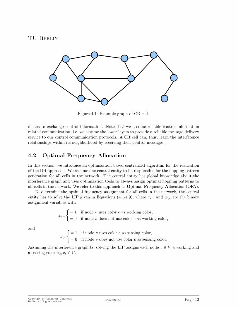
We use interference topology graphs to model the interference relationships among cells.An example graph is shown in Figure 4.1. Here, each node represents a CR cell. The presenceof an edge between two nodes (cells) indicates that they are within the interference rangeof each other. We define an interference topology graph G = (V,E), where V = {v1, ..., vn}denotes the CR cells and E is the set of interference relationships with (i, j) ∈ E if vi and vj
are in each others’ interference range. Additionally, we define Ni to be the set of neighboringnodes of i, i.e. j ∈ Ni if (i, j) ∈ E. Moreover, we assume the BSs of neighboring cells to have
1Recall that in IEEE 802.22 the most PUs are TV broadcasters which have a much larger interferencerange compared to 802.22 cells and do rarely change their usage.
Copyright at Technical UniversityBerlin. All Rights reserved.
TKN-08-001 Page 11
TU Berlin
Figure 4.1: Example graph of CR cells
means to exchange control information. Note that we assume reliable control informationrelated communication, i.e. we assume the lower layers to provide a reliable message deliveryservice to our control communication protocols. A CR cell can, thus, learn the interferencerelationships within its neighborhood by receiving their control messages.
4.2 Optimal Frequency Allocation
In this section, we introduce an optimization based centralized algorithm for the realizationof the DH approach. We assume one central entity to be responsible for the hopping patterngeneration for all cells in the network. The central entity has global knowledge about theinterference graph and uses optimization tools to always assign optimal hopping patterns toall cells in the network. We refer to this approach as Optimal Frequency Allocation (OFA).
To determine the optimal frequency assignment for all cells in the network, the centralentity has to solve the LIP given in Equations (4.1-4.9), where xc,v and yc,v are the binaryassignment variables with
xc,v
{= 1 if node v uses color c as working color,= 0 if node v does not use color c as working color,
and
yc,v
{= 1 if node v uses color c as sensing color,= 0 if node v does not use color c as sensing color.
Assuming the interference graph G, solving the LIP assigns each node v ∈ V a working anda sensing color cw, cs ∈ C.
Copyright at Technical UniversityBerlin. All Rights reserved.
TKN-08-001 Page 12
TU Berlin
min∑∀c∈C
bc +ac
|C|(4.1)
s. t.∑∀c∈C
xc,v = 1 ∀ v ∈ V (4.2)
xc,v + xc,w ≤ 1 ∀ c ∈ C ∧ ∀(v, w) ∈ E (4.3)∑∀c∈C
yc,v = 1 ∀ v ∈ V (4.4)
xc,v + yc,v ≤ 1 ∀(c, v) ∈ C × V (4.5)xc,v + yc,w ≤ 1 ∀ c ∈ C ∧ ∀(v, w) ∈ E (4.6)
yc,v +∑∀w∈Nv
yc,w ≤ Nq ∀(c, v) ∈ C × V (4.7)
ac ≥ xc,v ∀(c, v) ∈ C × V (4.8)bc ≥ yc,v ∀(c, v) ∈ C × V (4.9)
Constraint (4.2) assures that each node is assigned exactly one working color, and con-straint (4.3) assures that neighboring nodes do not get the same working color. Con-straint (4.4) assures that each node is assigned exactly one sensing color, constraint (4.5)assures that the working and sensing color for a node differ, and constraint (4.6) assuresthat the sensing color differs from the working color of neighboring nodes. Constraint (4.7)ensures that no more than Nq neighboring nodes share the same sensing color. Finally, bythe use of auxiliary variables ac (constraint (4.8)) and bc (constraint (4.9)) it is determinedwhether color c is used at all in the graph and are, thus, the variables to minimize. In orderto not only minimize the total number of colors, but also the sensing colors used in the graph,we set the minimization of bc as the primary objective.
Based on the solution of the LIP the central entity uses the color indices c in the graphcoloring problem as frequency indices and sensing slots in the CR network. All cells v withx1,v = 1 get assigned the frequency with index 1 and Nwf = 1; all cells with x2,v = 1 getassigned the frequency with index 2 and Nwf = 2 and so on. Additionally, each cell v withyi,v = 1 gets assigned the frequency with index i as sensing frequency, and the Nsf = i. Thefrequency assignments have to be distributed to all cells in the network. Additionally, thecentral entity has to recompute and redistribute the assignment as soon as there is any changein the interference relationship between the cells in the graph or a used frequency cannot beused anymore due to the appearance of a PU.
Note that solving the above LIP and, thus, the computation of the optimal frequencyassignment might require extremely long computation times. Figure 4.2 shows the averagerun-times of an Intel Pentium 4 3.20 GHz that solves the above LIP as part of our simulationsusing the standard optimization software CPLEX [22]. According to this, the expectedcomputation time increases exponentially with the number of nodes in the graph, whichposes some scalability concerns. Moreover, the message overhead required per cell to collectthe information about the whole interference graph at the central entity and to distributethe frequency assignments to the individual cells increases linearly with the average numberof hops to reach the central entity. Hence, as a consequence of the long computation times
Copyright at Technical UniversityBerlin. All Rights reserved.
TKN-08-001 Page 13

TU Berlin
10 20 30 40 50number of cells
0
1000
2000
3000
4000
cpu-
time
in s
econ
dsd=0.35d=0.5
Figure 4.2: CPU times for solving the LIP using CPLEX on an Intel Pentium 4 3.20 GHz
and the high control message overhead in larger networks, we consider this approach mainlyfor comparison reasons (serving as a lower bound in frequency usage) rather than proposingit for practical usage.
4.3 Distributed Frequency Allocation
In this section a distributed algorithm realizing the DH approach is described. We assumethat the cells only have information about their neighborhood, i.e. each cell knows its neigh-boring cells and has means to communicate with them. Additionally, a cell can learn thefrequency usage of its neighbors by exchanging control messages. A detailed description ofthe protocol realization and implementation, including state diagrams, can be found in [19].We refer to this approach as Distributed Frequency Allocation (DFA).
DFA is based on the Distributed Largest First (DLF) algorithm [20] originally designedto solve static FAPs. This approach is known to perform near to optimal for static FAPs inpractical problem instances. The basic idea of DLF is the following: After having discoveredtheir cell neighbors, each node of the graph (i.e. each cell) collects information about the nodedegree (number of neighboring nodes) of its neighbors. Each cell then chooses its workingfrequency depending on its node degree, where the cell with the highest node degree selects itsfrequency first. In the case of equal node degrees, a random number is used for tie breaking.A cell always chooses the frequency with the lowest index available and distributes its choicewithin the neighborhood. This method ensures that two neighboring cells cannot select thesame frequency (as only one frequency is chosen at a time).
The DLF is used for the initial working frequency (plus sensing slot – Nwf) selection. Inaddition, a sensing frequency (plus sensing slot – Nsf) has to be chosen. The first cell, thus– after choosing its working frequency – also “creates” a sensing frequency (again with thelowest frequency index available) and chooses a Nsf used to perform sensing on the sensingfrequency. All subsequent cells choose the same sensing frequency and Nsf if applicable (inaddition to a working frequency). If the sensing frequency or Nsf cannot be used the cell hasto choose a different sensing frequency or Nsf.
Whenever a cell reaches its Nwf, it switches data transmission from its working frequencyto its sensing frequency, and starts sensing. After tquiet it switches back to its old working
Copyright at Technical UniversityBerlin. All Rights reserved.
TKN-08-001 Page 14
TU Berlin
frequency if no PU appeared on that frequency. Otherwise, it starts data transmission on anew working frequency (with the lowest frequency index available), or – if no new workingfrequency could be found – switches to the non-hopping mode.
Whenever a cell reaches its Nsf, it has to sense its sensing frequency. If it is not vacantanymore, but a new one was found, the cell has to broadcast a message indicating the newsensing frequency to its neighbors. In case no new sensing frequency could be found, the cellswitches to the non-hopping mode.
In contrast to the optimal approach presented above, the computation time needed togenerate a frequency assignment is distributed among all cells. The time needed at every cellis negligible and does not increase with the number of cells in the network. Furthermore, thecontrol message overhead is also constant (one message per cell per frame time).
Copyright at Technical UniversityBerlin. All Rights reserved.
TKN-08-001 Page 15

TU Berlin
Chapter 5
Performance Analysis
In this chapter we present a performance analysis of the Distributed Frequency Allocation(DFA) algorithm and protocol. We compare the DFA with the DHA and benchmark bothagainst the optimal solution produced by the OFA.
5.1 Methodology
We have randomly generated interference topology graph instances using Culbersohn’s graphgenerator [21] on a 1 by 1 unit plane, with the number of nodes varying between |V | = 10 and|V | = 50. The nodes are connected (i.e. the cells are interfering) if their euclidian distance issmaller than or equal to d, where we vary this distance between d = 0.35 and d = 0.6. Wehave generated 80 random graph topologies for each of those (|V |, d) pairs. We assume thatdistinct frequency sets are used for the hopping and the non-hopping operation. Frequencies 1to Fnh−1 are used for the hopping mode; frequencies Fnh to Ftot are used for the non-hoppingmode. This concept enables us to support up to 2Nq neighboring CR cells in time shiftedoperation, i.e. in a collision-free operation (assuming that the exchange of control messagesis reliable). The simulation time for each simulation is set to 200 s. The quiet time is set totquiet = 0.1 s. The frequency sets are determined by Ftot = 50, and Fnh = 31, resulting in30 frequencies available for hopping operation and 20 frequencies available for non-hoppingoperation. The frame time is set to tframe = 2.0 s which results in tdata = 1.9 s for the DFAand OFA and tdata = 1.9 s for the DHA approach.
We investigate two initialization methods. In the optimal initialization, all cells startoperation synchronously using an initial hopping pattern determined by solving the LIP usingCPLEX [22] or using the DLF, respectively. In the random initialization, a cell randomlystarts operation within the first 10 s of the simulation. For OFA, the central entity has torecalculate all hopping patterns as soon as a new cell pops up. In DFA and DHA, after a cellpops up, it has to learn the interference relationships within its neighborhood by listening tocontrol messages from neighboring cells. Based on this information it chooses the frequenciesand sensing slots to use. The initialization phase of a cell is described in Appendix A.2 indetail.
Copyright at Technical UniversityBerlin. All Rights reserved.
TKN-08-001 Page 16
TU Berlin
10 20 30 40 50number of cells
0
10
20
30
40
max
imum
no.
of f
requ
enci
es DHADFAOFA (optimum)
hopping with optimal initialization
d=0.35
d=0.6
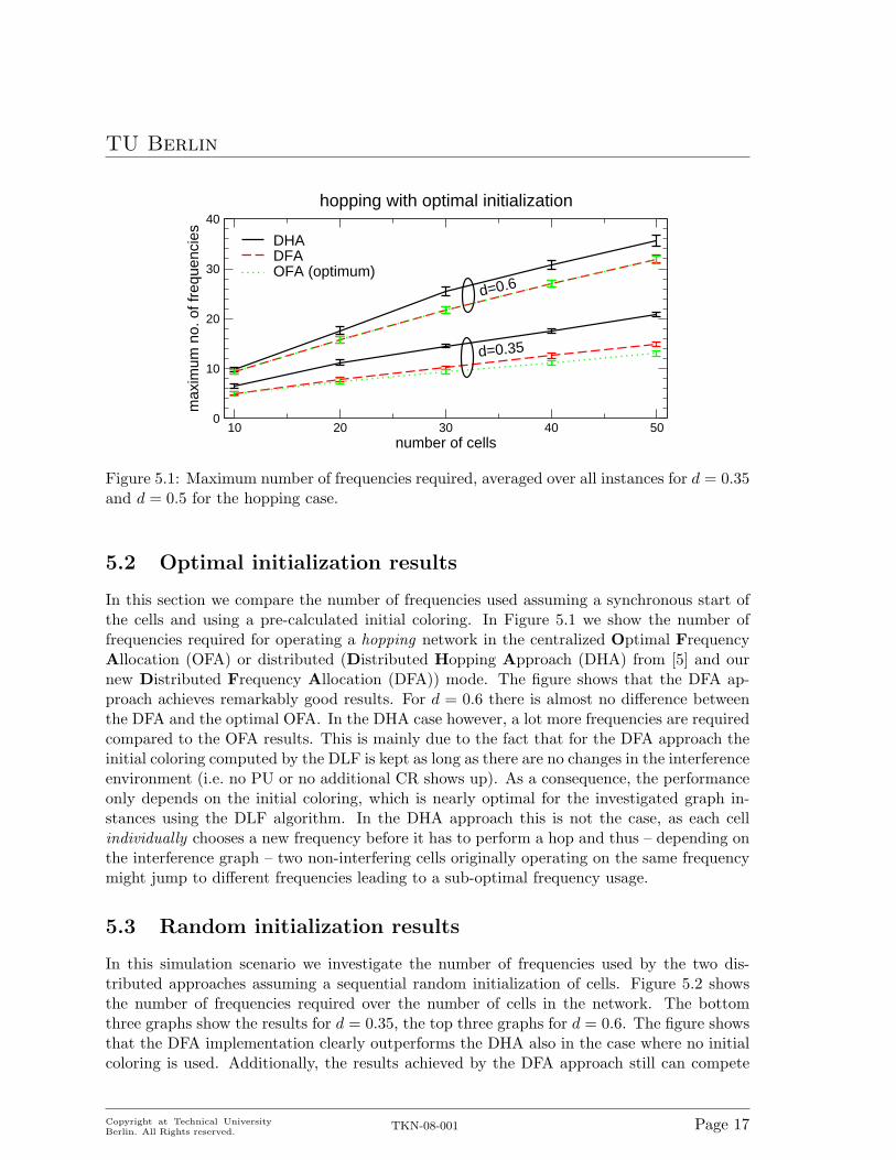
Figure 5.1: Maximum number of frequencies required, averaged over all instances for d = 0.35and d = 0.5 for the hopping case.
5.2 Optimal initialization results
In this section we compare the number of frequencies used assuming a synchronous start ofthe cells and using a pre-calculated initial coloring. In Figure 5.1 we show the number offrequencies required for operating a hopping network in the centralized Optimal FrequencyAllocation (OFA) or distributed (Distributed Hopping Approach (DHA) from [5] and ournew Distributed Frequency Allocation (DFA)) mode. The figure shows that the DFA ap-proach achieves remarkably good results. For d = 0.6 there is almost no difference betweenthe DFA and the optimal OFA. In the DHA case however, a lot more frequencies are requiredcompared to the OFA results. This is mainly due to the fact that for the DFA approach theinitial coloring computed by the DLF is kept as long as there are no changes in the interferenceenvironment (i.e. no PU or no additional CR shows up). As a consequence, the performanceonly depends on the initial coloring, which is nearly optimal for the investigated graph in-stances using the DLF algorithm. In the DHA approach this is not the case, as each cellindividually chooses a new frequency before it has to perform a hop and thus – depending onthe interference graph – two non-interfering cells originally operating on the same frequencymight jump to different frequencies leading to a sub-optimal frequency usage.
5.3 Random initialization results
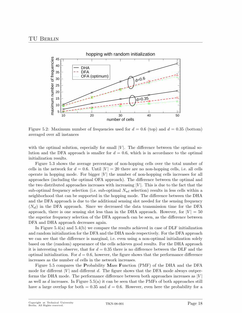
In this simulation scenario we investigate the number of frequencies used by the two dis-tributed approaches assuming a sequential random initialization of cells. Figure 5.2 showsthe number of frequencies required over the number of cells in the network. The bottomthree graphs show the results for d = 0.35, the top three graphs for d = 0.6. The figure showsthat the DFA implementation clearly outperforms the DHA also in the case where no initialcoloring is used. Additionally, the results achieved by the DFA approach still can compete
Copyright at Technical UniversityBerlin. All Rights reserved.
TKN-08-001 Page 17
TU Berlin
10 20 30 40 50number of cells
5
10
15
20
25
30
35
40
45
max
imum
num
ber
of fr
eque
ncie
s
DHADFAOFA (optimum)
hopping with random initialization
d=0.6
d=0.35
Figure 5.2: Maximum number of frequencies used for d = 0.6 (top) and d = 0.35 (bottom)averaged over all instances
with the optimal solution, especially for small |V |. The difference between the optimal so-lution and the DFA approach is smaller for d = 0.6, which is in accordance to the optimalinitialization results.
Figure 5.3 shows the average percentage of non-hopping cells over the total number ofcells in the network for d = 0.6. Until |V | = 20 there are no non-hopping cells, i.e. all cellsoperate in hopping mode. For bigger |V | the number of non-hopping cells increases for allapproaches (including the optimal OFA approach). The difference between the optimal andthe two distributed approaches increases with increasing |V |. This is due to the fact that thesub-optimal frequency selection (i.e. sub-optimal Nwf selection) results in less cells within aneighborhood that can be supported in the hopping mode. The difference between the DHAand the DFA approach is due to the additional sensing slot needed for the sensing frequency(Nsf) in the DFA approach. Since we decreased the data transmission time for the DFAapproach, there is one sensing slot less than in the DHA approach. However, for |V | = 50the superior frequency selection of the DFA approach can be seen, as the difference betweenDFA and DHA approach decreases again.
In Figure 5.4(a) and 5.4(b) we compare the results achieved in case of DLF initializationand random initialization for the DFA and the DHA mode respectively. For the DFA approachwe can see that the difference is marginal, i.e. even using a non-optimal initialization solelybased on the (random) appearance of the cells achieves good results. For the DHA approachit is interesting to observe, that for d = 0.35 there is no difference between the DLF and theoptimal initialization. For d = 0.6, however, the figure shows that the performance differenceincreases as the number of cells in the network increases.
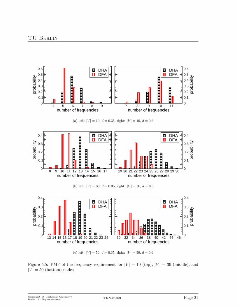
Figure 5.5 compares the Probability Mass Function (PMF) of the DHA and the DFAmode for different |V | and different d. The figure shows that the DFA mode always outper-forms the DHA mode. The performance difference between both approaches increases as |V |as well as d increases. In Figure 5.5(a) it can be seen that the PMFs of both approaches stillhave a large overlap for both = 0.35 and d = 0.6. However, even here the probability for a
Copyright at Technical UniversityBerlin. All Rights reserved.
TKN-08-001 Page 18

TU Berlin
10 20 30 40 50number of cells
0
0.1
0.2
0.3
aver
age
perc
enta
geof
non
-hop
ping
cel
ls
DHADFAOFA (optimum)
Figure 5.3: Average percentage of non-hopping cells for d = 0.6
10 20 30 40 50number of cells
0
5
10
15
20
25
30
35
max
imum
no.
of f
requ
enci
es DFA with DLF inititializationDFA with random initializationOFA (optimum) d=0.6
d=0.35
(a) Distributed Frequency Allocation
10 20 30 40 50number of cells
0
10
20
30
40
max
imum
no.
of f
requ
enci
es DHA with DLF initializationDHA with random initializationOFA (optimum)
d=0.6
d=0.35
(b) Distributed Hopping Approach
Figure 5.4: Comparison of the maximum frequency requirement in case of DLF and sequentialinitialization for the DFA (top) and the DHA (bottom) approach.
Copyright at Technical UniversityBerlin. All Rights reserved.
TKN-08-001 Page 19
TU Berlin
higher number of frequencies is lower for the DFA than for the DHA approach. Figure 5.5(b)shows the PMF for |V | = 30. Here, the overlap between the both approaches is alreadysmaller than for |V | = 10. Finally, Figure 5.5(c) shows the PMF for |V | = 50. Here, theperformance difference is biggest, i.e., the overlap between both approaches is smallest.
Copyright at Technical UniversityBerlin. All Rights reserved.
TKN-08-001 Page 20
TU Berlin
4 5 6 7 8 9number of frequencies
0
0.1
0.2
0.3
0.4
0.5
0.6
prob
abili
ty
DHADFA
7 8 9 10 11number of frequencies
0
0.1
0.2
0.3
0.4
0.5
0.6
prob
abili
ty
DHADFA
(a) left: |V | = 10, d = 0.35, right: |V | = 10, d = 0.6
8 9 10 11 12 13 14 15 16 17number of frequencies
0
0.1
0.2
0.3
0.4
prob
abili
ty
DHADFA
19 20 21 22 23 24 25 26 27 28 29 30number of frequencies
0
0.1
0.2
0.3
0.4
prob
abili
ty
DHADFA
(b) left: |V | = 30, d = 0.35, right: |V | = 30, d = 0.6
13 14 15 16 17 18 19 20 21 22 23 24number of frequencies
0
0.1
0.2
0.3
0.4
prob
abili
ty
DHADFA
30 32 34 36 38 40 42 44 46number of frequencies
0
0.1
0.2
0.3
0.4
prob
abili
ty
DHADFA
(c) left: |V | = 50, d = 0.35, right: |V | = 50, d = 0.6
Figure 5.5: PMF of the frequency requirement for |V | = 10 (top), |V | = 30 (middle), and|V | = 50 (bottom) nodes
Copyright at Technical UniversityBerlin. All Rights reserved.
TKN-08-001 Page 21

TU Berlin
Chapter 6
Conclusions
In this paper we have presented Double Hopping (DH), a new approach to apply Dyna-mic Frequency Hopping (DFH) in CR cellular networks. The presented approach allows forcontinuous data transmission in CR networks while enabling reliable detection of PrimaryUsers (PUs). Compared to Revolver Hopping (RH), which was proposed for DFH in CRcellular networks earlier, DH has one major advantage: Although the minimum number offrequencies required to operate a network of cells in DH mode is the same as for the RH mode,the number of frequencies required per cell is much lower for the DH approach. In the DHapproach each cell occupies two frequencies only, whereas in RH each cell hops through thewhole set of cells used by the network. On the other hand, each cell needs to hop twice asoften in the DH approach, and the coordination overhead to manage the frequency usage islarger than in RH.
We have applied graph coloring optimization to minimize the number of required frequen-cies in DFH cellular CR networks, in order to minimize potential Secondary User (SU) gen-erated interference on PUs and to maximize the number of supportable cells. Based on that,we have presented two realizations of DH: centralized Optimal Frequency Allocation (OFA)and Distributed Frequency Allocation (DFA). In our performance evaluation, we comparethe DFA with the Distributed Hopping Approach (DHA) a distributed implementation ofthe RH approach. The OFA realization results are used as a lower bound to benchmark thetwo distributed realizations. Our performance evaluation results show that the proposed DFAcan compete with the optimal results of the OFA and outperforms the DHA approach by far.The DHA approach needs significantly more frequencies, as it involves a higher dynamic infrequency usage (a single cell uses a plurality of frequencies). We, thus, have shown, that – asin the frequency-static case – distributed approaches for solving the Frequency AssignmentProblem (FAP) that achieve results comparable to the optimum exist.
Investigating the impact of PU dynamics is left as a future work issue. Another issue isto explore the impact of the amount of neighborhood information (i.e. the frequency usage ofneighboring cells) on the approaches. Currently, each cell has knowledge about its one-hopneighborhood only. The related research question to answer is if the approaches significantlygain from e.g. having two-hop neighborhood knowledge. Additionally, our preliminary resultsmotivate the introduction of cooperation between hopping cells by grouping cells into com-munities. Each community can be assumed to have regional information about its vicinity.The trade-off between the overhead to keep these informations up to date and the gain inperformance is another interesting optimization problem.
Copyright at Technical UniversityBerlin. All Rights reserved.
TKN-08-001 Page 22
TU Berlin
Appendix A
Distributed DFH Protocol
In this chapter, we present a distributed protocol realization for DFH. The protocol supportsDHA as well as DFA operation. Additionally, a non-hopping operation mode is implemented.If a cell cannot operate in DFH mode (either because no frequencies or no sensing slots areavailable) it tries to operate in non-hopping mode.
We assume that distinct frequency sets are used for the hopping and the non-hoppingoperation. Frequencies 1 to Fnh − 1 are used for the hopping mode; frequencies Fnh toFtot are used for the non-hopping mode. This concept enables us to support up to 2Nq
neighboring CR cells in phase-shifted operation, i.e. in a collision-free operation (assumingthat the exchange of control messages is reliable).
The described protocol has been implemented and tested using OMNeT++ [23] and themobility framework [24]. In the state diagrams the following acronyms are used: workingFreqfor working frequency (Fw), sensSlotWork for sensing slot for the working frequency (Nwf),sensingFreq for sensing frequency (Fs), and sensSlotSens for sensing slot for the sensingfrequency (Nsf).
A.1 Message types and timer
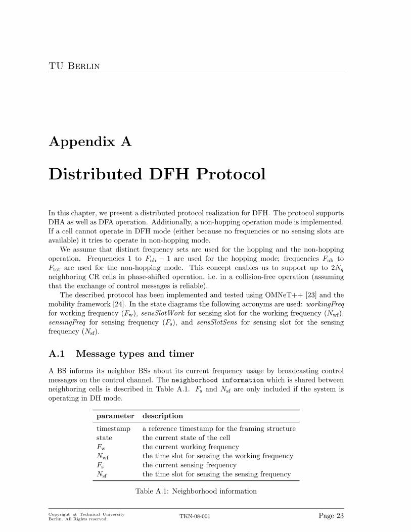
A BS informs its neighbor BSs about its current frequency usage by broadcasting controlmessages on the control channel. The neighborhood information which is shared betweenneighboring cells is described in Table A.1. Fs and Nsf are only included if the system isoperating in DH mode.
parameter description
timestamp a reference timestamp for the framing structurestate the current state of the cellFw the current working frequencyNwf the time slot for sensing the working frequencyFs the current sensing frequencyNsf the time slot for sensing the sensing frequency
Table A.1: Neighborhood information
Copyright at Technical UniversityBerlin. All Rights reserved.
TKN-08-001 Page 23

TU Berlin
name description
neighborInfo The neighborhood discovery message announces the existence andcurrent frequency usage of a cell.
jumpAnnounce The jump announcement message indicates that a cell jumped toa new frequency.
newSensFreq The new sensing frequency message indicates that the cellchanged its sensing frequency.
endListen The endListen timer indicates the end of the initial listen period.endInit The endInit timer indicates the end of the initialization phase
and the start of the hopping / non-hopping operation.sensWork The sensWork timer indicates the start for sensing the working
frequency.sensSens The sensSens timer indicates the start for sensing the sensing
frequency.
Table A.2: Messages and timers
We define three message types and four timers as described in Table A.2. All messagescontain the neighborhood information as described in Table A.1. A neighborInfo messageadditionally contains the start time of the cell, and a random number (used for tie breaking).
The sensing slots are to be understood with respect to the timestamp, where the time-stamp marks the beginning of a frame, i.e. the beginning of the first slot in the frame. Thestart time of sensing the working frequency (and thus also the time the sensWork timer isscheduled to) is thus “timestamp + (Nwf − 1) · tquiet”. The sensing is finished one slot (tquiet
time units). At that time also the jump to the new frequency is performed.
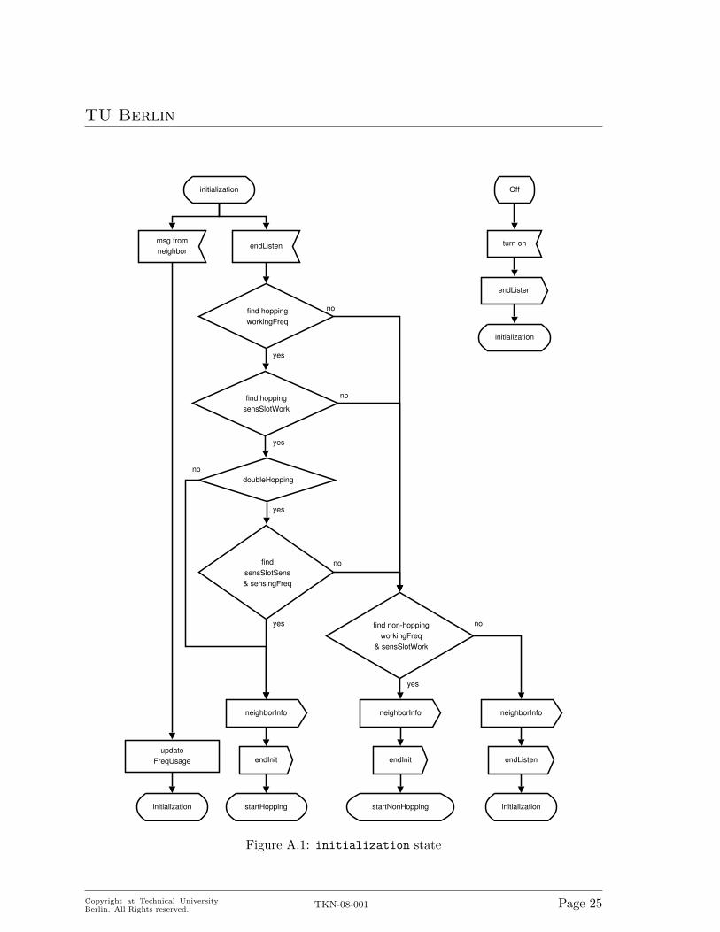
A.2 initialization state
After a cell is powered on, it is in the initialization state. It immediately broadcasts aneighborhood discovery (neighborInfo) message to announce its existence to its neighbors.Since no frequencies or sensing slots are selected yet, the respective values in the neighborhoodinformation are set to −1. Subsequently, it sets the endListen timer and listens for messagesfrom its neighbors to get a list of active neighbors and their frequency usage. If a message froma neighbor arrives, the frequency usage is updated, which means, that (1) the neighborhoodinformation for the neighbor is updated and (2) the frequency list is updated. Updating thefrequency list means, that the working frequency and Nwf of the neighbor is marked used andthat the sensing frequency and Nsf are marked as sensing frequency and Nsf, so that theycan also be used by this cell if applicable.
Once the initial listen period is over, the cell has full knowledge about its neighborhoodand, thus, also about the frequencies used within its neighborhood. It then tries to find anavailable hopping working frequency and proceeds as described in Chapter A.2. If no hoppingfrequency is available as working frequency, it tries to find a non-hopping working frequencyand proceeds as described in Chapter A.2. A state diagram for the initialization state canbe found in Figure A.1.
Copyright at Technical UniversityBerlin. All Rights reserved.
TKN-08-001 Page 24
TU Berlin
endListen
initialization
find hoppingworkingFreq
find hoppingsensSlotWork
yes
findsensSlotSens& sensingFreq
doubleHopping
yes
yes
startHopping
yes find non-hoppingworkingFreq
& sensSlotWork
no
no
no
no
startNonHopping
yes
no
neighborInfo neighborInfo neighborInfo
endInit endInit
initialization
Off
turn on
endListen
initialization
initialization
endListenupdate
FreqUsage
msg fromneighbor
Figure A.1: initialization state
Copyright at Technical UniversityBerlin. All Rights reserved.
TKN-08-001 Page 25
TU Berlin
Hopping initialization
After having found a working frequency, the cell has to find a sensing slot for its workingfrequency (Nwf). The assumption is, that neighbors are not allowed to sense their workingfrequency (and thus hop to a new frequency) at the same time. This ensures a collision-freeoperation of neighboring CR cells. If no Nwf can be found, the cell tries to start operation innon-hopping mode as described in Section A.2.
In the DH mode, the cell additionally needs a sensing frequency and a sensing slot forthe sensing frequency (Nsf). As shown in Chapter 3, neighboring cells should ideally use thesame sensing frequency as well as the same slot for sensing the sensing frequency (Nsf). Thus,the cell first tries to use a sensing frequency and Nsf already used by its neighbors. Only ifthis is not possible it starts a new sensing frequency or chooses a different Nsf. If either nosensing frequency or no Nsf was found the cell tries to start operation in non-hopping modeas described in Section A.2.
After choosing the frequencies and sensing slots a neighborInfo message with the stateset to startHopping is sent to announce the intended frequency usage to the neighbors. AnendInit timer is set to the Nwf, where the initialization phase will be over and the cell startsto use the working frequency for the first time. The cell switches to the startHopping stateshown in Figure A.2 and described in Section A.3.
Non-hopping initialization
If no Nwf (Nsf) was found for the working frequency (sensing frequency) or the cell cannotfind a working or sensing frequency, it has to try to operate in non-hopping mode.
For the non-hopping mode, the cell has to find a working frequency in the non-hoppingfrequency range not used by any other neighboring cell. If successful, it has to find a Nwf notused by any non-hopping neighbor-cell.
On success, the cell switches to the startNonHopping state (shown in Figure A.3 anddescribed in Section A.3) and sets the endInit timer to the Nwf as in the hopping initializa-tion. It also broadcasts a neighborInfo message to announce the intended frequency usage.If no working frequency or Nwf can be found, the cell has to stay in the initializationstate and reset the endListen timer.
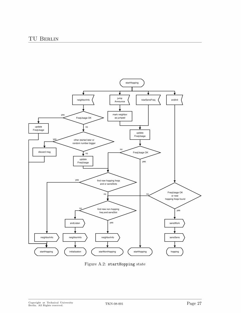
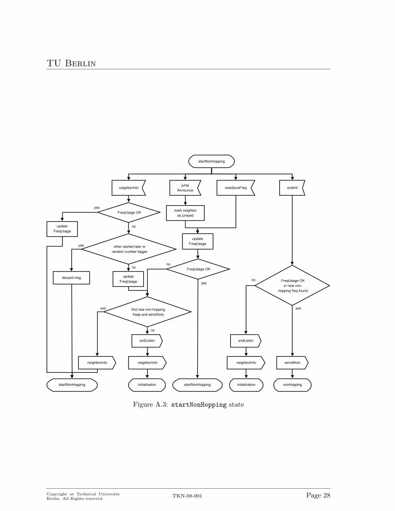
A.3 startHopping / startNonHopping state
In the startHopping state and startNonHopping state potential collisions in the workingand sensing frequency or sensing slots due to simultaneously starting cells are resolved. If acell receives a neighborInfo message with conflicting frequencies or sensing slots, the starttimes of the two cells are compared. The cell with the smaller start time wins. If the starttimes are equal, the random number is used, where the cell with the smaller random numberwins. The cell which looses, has to resolve the conflict (i.e. find new frequencies and / orsensing slots) and broadcast its new information in a neighborInfo message. The statediagrams are shown in Figure A.2 and Figure A.3 respectively.
If a jump announcement (jumpAnnounce) message or new sensing frequency (newSensFreq)message is received which contains conflicting frequencies or sensing slots, the conflicts have
Copyright at Technical UniversityBerlin. All Rights reserved.
TKN-08-001 Page 26
TU Berlin
startHopping
neighborInfojump
AnnouncenewSensFreq
mark neighboras jumped
FreqUsage OK
updateFreqUsage
other started later orrandom number bigger
discard msg
find new hopping freqsand or sensSlots
find new non-hoppingfreq and sensSlot
updateFreqUsage yes
FreqUsage OK
updateFreqUsage
yes
no
yes
no
startHopping
no
yes
yes
initialization
no
no
endInit
FreqUsage OKor new
hopping freqs found
yes
no
hoppingstartHopping
sensWork
sensSens
startNonHopping
neighborInfoneighborInfoneighborInfo
endListen
Figure A.2: startHopping state
Copyright at Technical UniversityBerlin. All Rights reserved.
TKN-08-001 Page 27
TU Berlin
startNonHopping
neighborInfojump
AnnouncenewSensFreq
mark neighboras jumped
updateFreqUsage
other started later orrandom number bigger
find new non-hoppingfreqs and sensSlots
updateFreqUsage
FreqUsage OKyes
no
yes
no
yes
endInit
FreqUsage OKor new non-
hopping freq found
yes
no
initialization
sensWork
nonHopping
neighborInfo
endListen
no
discard msg
updateFreqUsage
FreqUsage OK
yes
startNonHopping
no
startNonHopping
neighborInfo
initialization
neighborInfo
endListen
Figure A.3: startNonHopping state
Copyright at Technical UniversityBerlin. All Rights reserved.
TKN-08-001 Page 28
TU Berlin
to be resolved by the cell. Cells that currently are in the initialization phase have to integratethemselves into the existing frequency usage of cells already in the hopping / nonHoppingstate. A received jumpAnnounce or newSensFreq message indicates that the originator isalready in the hopping / nonHopping state, which is why the conflict has to be resolved bythe cell that currently is in the initialization phase.
The endInit timer expires at the beginning of the slot for sensing the working frequency(Nwf). The chosen frequencies have to be sensed again, to assure, that no PU appeared inthe meantime. If the frequency usage is still OK or an alternative working frequency can befound, the cell switches to the hopping / nonHopping state and performs its first jump asdescribed in Chapter A.4 and Chapter A.6 respectively. Finally, the sensWork timer and inDH mode also the sensSens timer have to be set.
If the frequency usage is not OK, i.e. some frequency cannot be used anymore, the cellcannot start operation. In the startHopping state, the cell tries to find a non-hoppingworking frequency and Nwf and – if successful – resets the endInit timer and switches to thestartNonHopping state. If no non-hopping frequency and Nwf can be found the cell has togo back to the initialization state. If the cell is in the startHonHopping state and thefrequency usage is not OK the cell also has to go back into the initialization state. In anycase a neighborInfo message is broadcasted to announce the new state to the neighbors.
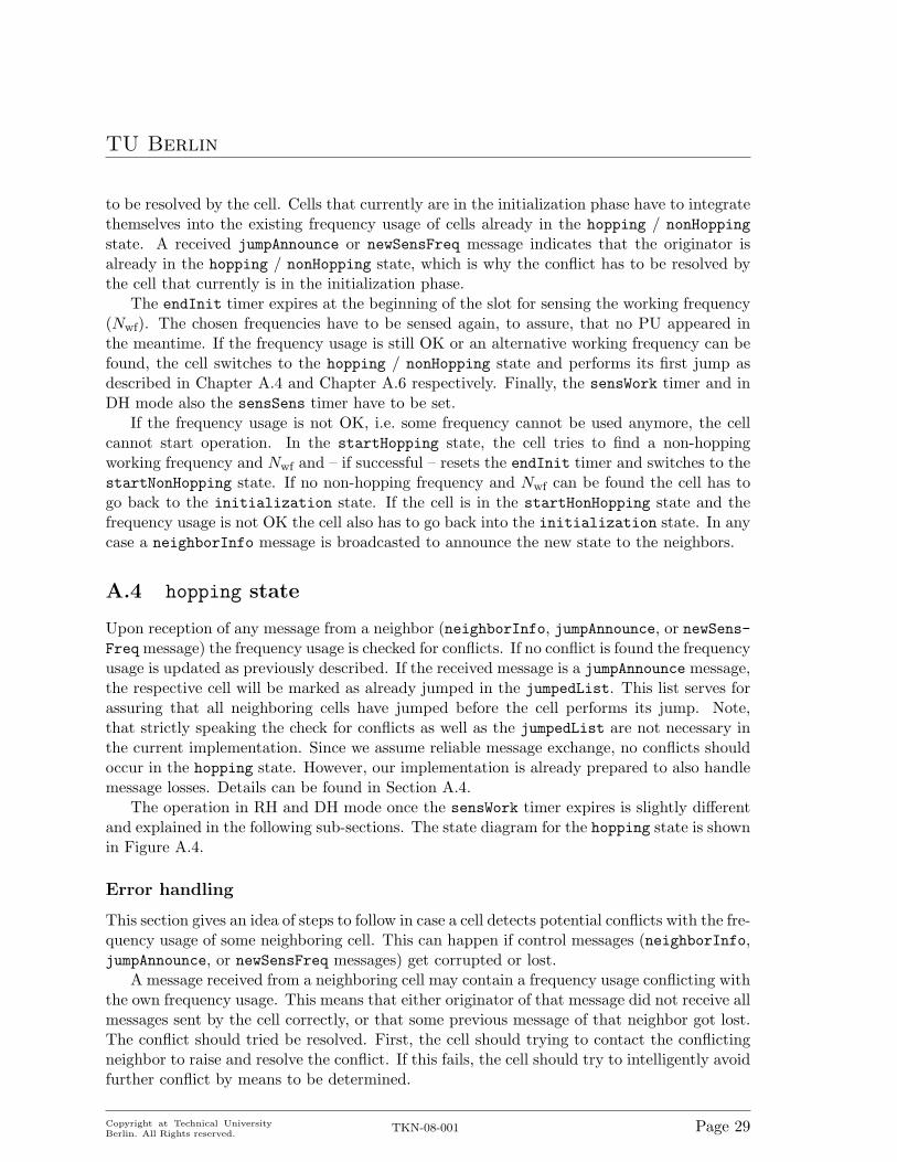
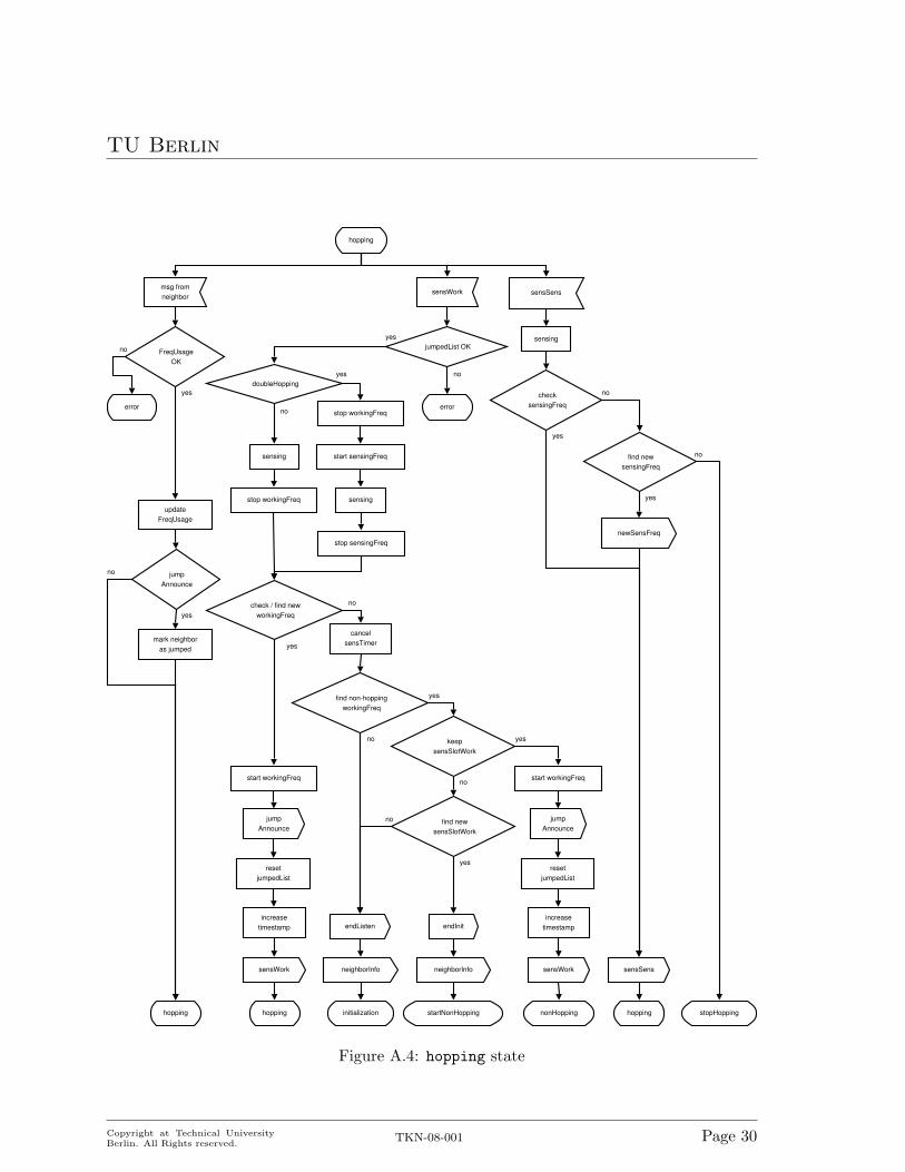
A.4 hopping state
Upon reception of any message from a neighbor (neighborInfo, jumpAnnounce, or newSens-Freq message) the frequency usage is checked for conflicts. If no conflict is found the frequencyusage is updated as previously described. If the received message is a jumpAnnounce message,the respective cell will be marked as already jumped in the jumpedList. This list serves forassuring that all neighboring cells have jumped before the cell performs its jump. Note,that strictly speaking the check for conflicts as well as the jumpedList are not necessary inthe current implementation. Since we assume reliable message exchange, no conflicts shouldoccur in the hopping state. However, our implementation is already prepared to also handlemessage losses. Details can be found in Section A.4.
The operation in RH and DH mode once the sensWork timer expires is slightly differentand explained in the following sub-sections. The state diagram for the hopping state is shownin Figure A.4.
Error handling
This section gives an idea of steps to follow in case a cell detects potential conflicts with the fre-quency usage of some neighboring cell. This can happen if control messages (neighborInfo,jumpAnnounce, or newSensFreq messages) get corrupted or lost.
A message received from a neighboring cell may contain a frequency usage conflicting withthe own frequency usage. This means that either originator of that message did not receive allmessages sent by the cell correctly, or that some previous message of that neighbor got lost.The conflict should tried be resolved. First, the cell should trying to contact the conflictingneighbor to raise and resolve the conflict. If this fails, the cell should try to intelligently avoidfurther conflict by means to be determined.
Copyright at Technical UniversityBerlin. All Rights reserved.
TKN-08-001 Page 29
TU Berlin
hopping
msg fromneighbor
updateFreqUsage
FreqUsageOK
yes
error
no
mark neighboras jumped
jumpAnnounce
no
hopping
sensWork sensSens
jumpedList OK
no
yes
check / find newworkingFreq
jumpAnnounce
resetjumpedList
increasetimestamp
hopping
yes
cancelsensTimer
no
sensWork
find non-hoppingworkingFreq
yes
no
yes
endInit
neighborInfo
startNonHopping
neighborInfo
initialization
endListen
keepsensSlotWork
find newsensSlotWork
jumpAnnounce
resetjumpedList
increasetimestamp
nonHopping
sensWork
yes
no
yes
no
find newsensingFreq
no
stopHopping
checksensingFreq
no
yes
yes
newSensFreq
sensSens
hopping
doubleHopping
sensing
no
stop workingFreq
start workingFreq
yes
start workingFreq
stop workingFreq
start sensingFreq
sensing
stop sensingFreq
error
sensing
Figure A.4: hopping state
Copyright at Technical UniversityBerlin. All Rights reserved.
TKN-08-001 Page 30
TU Berlin
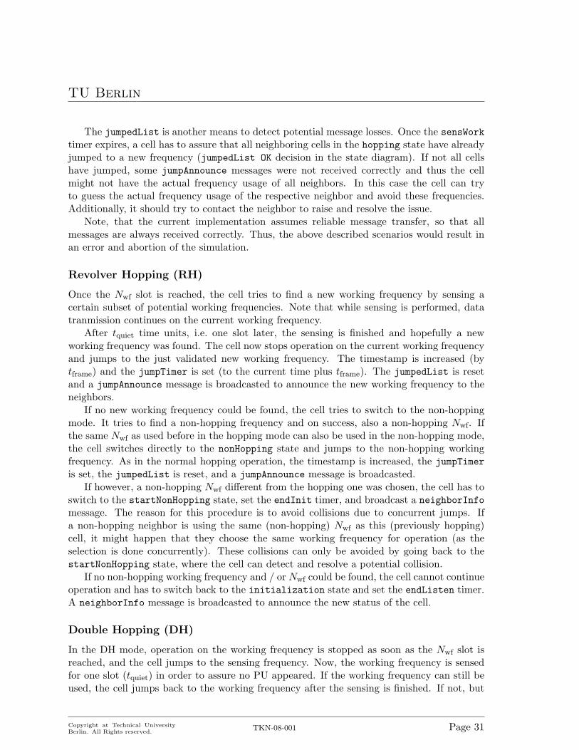
The jumpedList is another means to detect potential message losses. Once the sensWorktimer expires, a cell has to assure that all neighboring cells in the hopping state have alreadyjumped to a new frequency (jumpedList OK decision in the state diagram). If not all cellshave jumped, some jumpAnnounce messages were not received correctly and thus the cellmight not have the actual frequency usage of all neighbors. In this case the cell can tryto guess the actual frequency usage of the respective neighbor and avoid these frequencies.Additionally, it should try to contact the neighbor to raise and resolve the issue.
Note, that the current implementation assumes reliable message transfer, so that allmessages are always received correctly. Thus, the above described scenarios would result inan error and abortion of the simulation.
Revolver Hopping (RH)
Once the Nwf slot is reached, the cell tries to find a new working frequency by sensing acertain subset of potential working frequencies. Note that while sensing is performed, datatranmission continues on the current working frequency.
After tquiet time units, i.e. one slot later, the sensing is finished and hopefully a newworking frequency was found. The cell now stops operation on the current working frequencyand jumps to the just validated new working frequency. The timestamp is increased (bytframe) and the jumpTimer is set (to the current time plus tframe). The jumpedList is resetand a jumpAnnounce message is broadcasted to announce the new working frequency to theneighbors.
If no new working frequency could be found, the cell tries to switch to the non-hoppingmode. It tries to find a non-hopping frequency and on success, also a non-hopping Nwf. Ifthe same Nwf as used before in the hopping mode can also be used in the non-hopping mode,the cell switches directly to the nonHopping state and jumps to the non-hopping workingfrequency. As in the normal hopping operation, the timestamp is increased, the jumpTimeris set, the jumpedList is reset, and a jumpAnnounce message is broadcasted.
If however, a non-hopping Nwf different from the hopping one was chosen, the cell has toswitch to the startNonHopping state, set the endInit timer, and broadcast a neighborInfomessage. The reason for this procedure is to avoid collisions due to concurrent jumps. Ifa non-hopping neighbor is using the same (non-hopping) Nwf as this (previously hopping)cell, it might happen that they choose the same working frequency for operation (as theselection is done concurrently). These collisions can only be avoided by going back to thestartNonHopping state, where the cell can detect and resolve a potential collision.
If no non-hopping working frequency and / or Nwf could be found, the cell cannot continueoperation and has to switch back to the initialization state and set the endListen timer.A neighborInfo message is broadcasted to announce the new status of the cell.
Double Hopping (DH)
In the DH mode, operation on the working frequency is stopped as soon as the Nwf slot isreached, and the cell jumps to the sensing frequency. Now, the working frequency is sensedfor one slot (tquiet) in order to assure no PU appeared. If the working frequency can still beused, the cell jumps back to the working frequency after the sensing is finished. If not, but
Copyright at Technical UniversityBerlin. All Rights reserved.
TKN-08-001 Page 31
TU Berlin
a new working frequency was found, the cell jumps to the new working frequency. As in theRH mode the timestamp is increased, the jumpTimer is set, the jumpedList is reset, and ajumpAnnounce message is broadcasted.
If no hopping working frequency could be found, the cell cancels the sensSens timerand tries to switch to the non-hopping mode as described above for the RH. If operation innon-hopping mode is not possible either, the cell has to switch back to the initializationstate and set the endListen timer. A neighborInfo message is broadcasted to announcethe new status of the cell.
In the DH mode, the sensing frequency also has to be sensed periodically. This is alwaysdone during the Nsf slot. If the sensing frequency cannot be used anymore, the cell triesto find a new sensing frequency and – upon success – has to broadcast the new frequencyusage in a newSensFreq message. If the old sensing frequency is still usable no message isbroadcasted. In both cases the sensTimer is set (to the current time plus tframe).
If the old sensing frequency is not usable anymore and no new sensing frequency couldbe found, the cell has to switch to the stopHopping state until the next sensing period forthe working frequency. The sensTimer is not set again in this case.
A.5 stopHopping state
The stopHopping state only exists for the DH mode. A cell has to switch to the stopHoppingstate if no new sensing frequency can be found as described above. Incoming messages arehandled exactly the same way as in the hopping state described in Section A.4. The statediagram for the stopHopping state is shown in Figure A.5.
If the Nwf slot is reached, transmission on the working frequency has to be stopped.Since no valid sensing frequency was found, the cell cannot switch to the sensing frequency tocontinue data transmission and, thus, has to interrupt payload communication. However, thecell tries to switch to the non-hopping mode i.e. tries to find a non-hopping working frequencyand sensing slot as described in Chapter A.4. If that is not possible the cell has to go back tothe initialization state, set the endListen timer, and broadcast a neighborInfo message.
A.6 nonHopping state
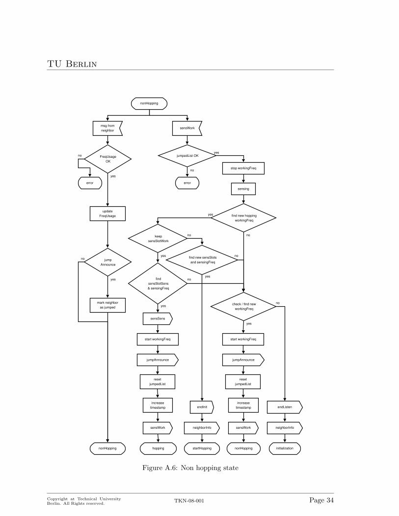
Incoming message handling in the nonHopping state is the same as in the hopping statedescribed earlier. The frequency usage is checked, updated, and the neighbor is marked asjumped if the message was a jumpAnnounce. The state diagram for the nonHopping state isshown in Figure A.6.
Once the Nwf slot is reached, data-tranmission has to be stopped on the working frequencyin order to perform sensing. During the sensing, the cell not only checks whether it still canuse its old (non-hopping) working frequency but also tries to find a hopping working frequencyin order to go back to the hopping mode as it is the preferable operation mode. If a hoppingworking frequency was found the cell tries to keep its non-hopping Nwf slot. If it cannot keepthe sensing slot, it tries to find a new one. Depending on whether or not the Nwf can bekept, the cell switches to the startHopping or directly to the hopping state, provided a Nsf
Copyright at Technical UniversityBerlin. All Rights reserved.
TKN-08-001 Page 32

TU Berlin
stopHopping
msg fromneighbor
updateFreqUsage
FreqUsageOK
yes
no
mark neighboras jumped
jumpAnnounce
no
stopHopping
sensWork
jumpedList OK
no
yes
find non-hoppingworkingFreq
yes
no
yes
endInit
neighborInfo
startNonHopping
neighborInfo
initialization
endListen
keepsensSlotWork
find newsensSlotWork
jumpAnnounce
resetjumpedList
increasetimestamp
nonHopping
sensWork
yes
no
yes
no
errorerror
sensing
stop workingFreq
start workingFreq
Figure A.5: stopHopping state
Copyright at Technical UniversityBerlin. All Rights reserved.
TKN-08-001 Page 33
TU Berlin
nonHopping
msg fromneighbor
updateFreqUsage
FreqUsageOK
yes
error
no
mark neighboras jumped
jumpAnnounce
no
nonHopping
sensWork
jumpedList OK
error
no
yes
yes
check / find newworkingFreq
jumpAnnounce
resetjumpedList
increasetimestamp
nonHopping
yes
no
sensWork neighborInfo
initialization
endListen
find new hoppingworkingFreq
yes
no
endInit
neighborInfo
startHopping
keepsensSlotWork
find new sensSlotsand sensingFreq
jumpAnnounce
resetjumpedList
increasetimestamp
hopping
sensWork
yes
no
yes
no
findsensSlotSens& sensingFreq
sensSens
yes
no
sensing
stop workingFreq
start workingFreq start workingFreq
Figure A.6: Non hopping state
Copyright at Technical UniversityBerlin. All Rights reserved.
TKN-08-001 Page 34
TU Berlin
slot and sensing frequency was found. The reason for differentiating between keeping the oldNwf or choosing a new one is the same as described for the hopping state.
If the cell cannot switch back to the hopping mode, it has to revalidate its old non-hopping working frequency or find a new one. Upon success it starts operation on the workingfrequency. The timestamp is increased (by tframe) and the jumpTimer is set (to the currenttime plus tframe). The jumpedList is reset and a jumpAnnounce message is broadcasted toannounce the new working frequency to the neighbors.
If the old working frequency is not usable anymore and no new working frequency couldbe found, the cell has to go back to the initialization state, set the endListen timer, andbroadcast a neighborInfo message.
A.7 Time synchronization
In order to synchronize the hopping patterns of neighboring nodes, the timestamps need tobe synchronized. To do so, the timestamp of every received message is compared with theown timestamp. The timestamps are compared modulo tframe in order to determine whichone has the earlier frame start. If the timestamp contained in the message has an earlierframe start, it is copied, otherwise it is ignored.
The Nwf slot has to be translated to the new timestamp, i.e. the absolute time for sensingthe working frequency does not change, only the Nwf slot due to the new timestamp.
In DH mode the Nsf slot is copied from the neighbor with the smaller timestamp, if thatslot is still available, i.e. the absolute time for sensing the sensing frequency changes. Onsuccess a neighborInfo message is broadcasted.
The reason for trying to adapt the Nsf slot from the neighbor is that with this approachthe slots used for sensing the sensing frequency are reduced. As explained in Chapter 3,ideally all neighbors should perform sensing of the sensing frequency at the same time. Themore different Nsf slots are used, the less neighbors can fit into the hopping structure.
However, it might happen that the Nsf slot from the neighbor is not usable, as it is usedas a Nwf slot by some other neighbor. In this case the old Nsf slot has to be translated in thesame way as the Nwf slot.
Copyright at Technical UniversityBerlin. All Rights reserved.
TKN-08-001 Page 35

TU Berlin
Appendix B
Acronyms
AFH Adaptive Frequency Hopping
BS Base Station
CCI Co-Channel Interference
CDH Common Double Hopping
CR Cognitive Radio
DFH Dynamic Frequency Hopping
DFHC Dynamic Frequency Hopping Community
DH Double Hopping
DFA Distributed Frequency Allocation
DHA Distributed Hopping Approach
DLF Distributed Largest First
FAP Frequency Assignment Problem
IDH Individual Double Hopping
GSM Global System for Mobile Communications
LIP Linear Integer Program
MAL Mobile Allocation List
OFA Optimal Frequency Allocation
PER Packet Error Rate
PMF Probability Mass Function
PU Primary User
Copyright at Technical UniversityBerlin. All Rights reserved.
TKN-08-001 Page 36
TU Berlin
QoS Quality of Service
RH Revolver Hopping
SU Secondary User
TDMA Time Division Multiple Access
WLAN Wireless Local Area Network
WRAN Wireless Regional Area Network
|V | total number of CR cells in the network
Ftot total number of frequencies available for secondary communication
Fnh first non-hopping frequency
tmax maximal interference time
tsens sensing time [ms]
tquiet quiet time [ms]
tdata data transmission time [ms]
tframe frame time [ms]
Nq number of quiet times (tquiet) per data transmission time (tdata)
Nwf sensing slot for the working frequency
Nsf sensing slot for the sensing frequency
Fw working frequency
Fs sensing frequency
Copyright at Technical UniversityBerlin. All Rights reserved.
TKN-08-001 Page 37
TU Berlin
Bibliography
[1] L. Chu, W. Hu, G. Vlantis, J. Gross, M. Abusubaih, D. Willkomm, and A. Wolisz, “Dynamic fre-quency hopping community,” online, IEEE 802.22 Working Group, Technical proposal submittedto IEEE 802.22 WG 22-06-0113, Jun. 2006.
[2] W. Hu, D. Willkomm, L. Chu, M. Abusubaih, J. Gross, G. Vlantis, M. Gerla, and A. Wolisz,“Dynamic frequency hopping communities for efficient IEEE 802.22 operation,” IEEE Commun.Mag., Special Issue: ”Cognitive Radios for Dynamic Spectrum Access”, vol. 45, no. 5, pp. 80–87,May 2007.
[3] A. Eisenblaetter and A. Koster, “FAP web page,” http://fap.zib.de, 2000.[4] K. H. Rosen, Discrete Mathematics and Its Applications. McGraw-Hill Higher Education, 1998.[5] D. Hollos, D. Willkomm, J. Gross, and W. Hu, “Centralized vs. distributed frequency assignment
in frequency hopping (cognitive radio) cellular networks,” Telecommunication Networks Group,Technische Universitat Berlin, Tech. Rep. TKN-07-007, Dec. 2007.
[6] P. Bjorklund, P. Varbrand, and D. Yuan, “Optimal frequency planning in mobile networks withfrequency hopping,” Computers and Operations Research, vol. 32, pp. 169–186, 2005.
[7] J. Moon, L. Hughes, and D. Smith, “Assignment of frequency lists in frequency hopping net-works,” IEEE Trans. Veh. Technol., vol. 54, no. 3, pp. 1147–1159, 2005.
[8] Z. Kostic, I. Maric, and X. Wang, “Fundamentals of dynamic frequency hopping in cellularsystems,” IEEE J. Sel. Areas Commun., vol. 19, no. 11, pp. 2254–2266, Nov. 2001.
[9] M. Cho-Hoi Chek and Y.-K. Kwok, “On adaptive frequency hopping to combat coexistence inter-ference between bluetooth and IEEE 802.11b with practical resource constraints,” in Proceedingsof the 7th International Symposium on Parallel Architectures, Algorithms and Networks, 2004,pp. 391–396.
[10] B. Zhen, Y. Kim, and K. Jang, “The analysis of coexistence mechanisms of bluetooth,” in Pre-ceedings of the 55th IEEE Vehicular Technology Conference, 2002. (VTC Spring 2002), vol. 1,May 2002, pp. 419–423.
[11] H. Yomo, P. Popovski, H. Nguyen, and R. Prasad, “Adaptive frequency rolling for coexistence inthe unlicensed band,” IEEE Trans. Wireless Commun., vol. 6, no. 2, pp. 598–608, 2007.
[12] A. Mishra, V. Shrivastava, D. Agrawal, S. Banerjee, and S. Ganguly, “Distributed channel man-agement in uncoordinated wireless environments,” in Proceedings of the 12th annual internationalconference on Mobile computing and networking (MobiCom 2006). New York, NY, USA: ACM,2006, pp. 170–181.
[13] “IEEE 802.22 working group,” online. [Online]. Available: http://www.ieee802.org/22[14] B. Sanso and P. Soriano, Eds., Telecommunications Network Planning. Norwell, MA, USA:
Kluwer Academic Publishers, 1998.[15] A. Koster, “Frequency assignment: Models and algorithms,” Ph.D. dissertation, Universiteit
Maastricht, 1999.[16] C. Peng, H. Zheng, and B. Y. Zhao, “Utilization and fairness in spectrum assignment for op-
Copyright at Technical UniversityBerlin. All Rights reserved.
TKN-08-001 Page 38
TU Berlin
portunistic spectrum access,” Mobile Networks and Applications, vol. 11, no. 4, pp. 555–576,2006.
[17] S. Sengupta, S. Brahma, M. Chatterjee, and S. Shankar N, “Enhancements to cognitive radiobased IEEE 802.22 air-interface,” in Proceedings of the IEEE International Conference on Com-munications, 2007 (ICC ’07), 24-28 June 2007, pp. 5155–5160.
[18] IEEE802.22, “IEEE P802.22/D0.1 draft standard for wireless regional area networks part 22:Cognitive wireless ran medium access control (MAC) and physical layer (PHY) specifications:Policies and procedures for operation in the TV bands,” IEEE 802.22 Working Group, DraftStandard, 2006.
[19] D. Willkomm, M. Bohge, D. Hollos, and J. Gross, “Double hopping: A new approach for dynamicfrequency hopping in cognitive radio networks,” Telecommunication Networks Group, TechnischeUniversitat Berlin, Tech. Rep. TKN-08-001, Jan. 2008.
[20] M. Kubale and L. Kuszner, “A better practical algorithm for distributed graph coloring,” in Pro-ceedings of the IEEE International Conference on Parallel Computing in Electrical Engineering2002 (PARELEC 02). IEEE, 2002, pp. 72 – 76.
[21] J. Culberson, A. Beacham, and D. Papp, “Hiding our colors,” in CP’95 Workshop on Studyingand Solving Really Hard Problems, Cassis, France, 1995, pp. 31–42.
[22] S. ILOG, “CPLEX solver,” 2007, (accessed 04. Mai 2007). [Online]. Available: http://www.ilog.fr/products/cplex/
[23] A. Varga, OMNeT++ Discrete Event Simulation System. [Online]. Available: http://www.omnetpp.org/doc/manual/usman.html
[24] “Mobility framework (MF) for simulating wireless and mobile networks using OMNeT++.”[Online]. Available: http://mobility-fw.sourceforge.net/
Copyright at Technical UniversityBerlin. All Rights reserved.
TKN-08-001 Page 39