Embed Size (px)
Citation preview

DOT MATRIX PRINTER
SP200F SERIES
USER’S MANUALMODE D’EMPLOI
BEDIENUNGSANLEITUNGMANUALE DI ISTRUZIONI

Federal Communications CommissionRadio Frequency Interference
StatementThis equipment has been tested and found to comply with the limits for a Class A digitaldevice, pursuant to Part 15 of the FCC Rules. These limits are designed to providereasonable protection against harmful interference when the equipment is operated in acommercial environment. This equipment generates, uses and can radiate radio frequencyenergy and, if not installed and used in accordance with the instruction manual, may causeharmful interference to radio communications. Operation of this equipment in a residentialarea is likely to cause harmful interference in which case the user will be required to correctthe interference at his own expense.For compliance with the Federal Noise Interference Standard, this equipment requires ashielded cable.This statement will be applied only for the printers marketed in U.S.A.
Statement ofThe Canadian Department of Communications
Radio Interference RegulationsThis digital apparatus does not exceed the Class A limits for radio noise emissions fromdigital apparatus set out in the Radio Interference Regulations of the Canadian Departmentof Communications.Le présent appareil numérique n’émet pas de bruits radioélectriques dépassant les limitesapplicables aux appareils numériques de la classe A prescrites dans le Règlement sur lebrouillage radioélectrique édicté par le ministère des Communications du Canada.The above statement applies only to printers marketed in Canada.
CEManufacturer’s Declaration of Conformity
EC Council Directive 89/336/EEC of 3 May 1989This product, has been designed and manufactured in accordance with the InternationalStandards EN 50081-1/01.92 and EN 50082-1/01.92, following the provisions of theElectro Magnetic Compatibility Directive of the European Communities as of May 1989.
EC Council Directive 73/23/EEC and 93/68/EEC of 22 July 1993This product, has been designed and manufactured in accordance with the InternationalStandards EN 60950, following the provisions of the Low Voltage Directive of theEuropean Communities as of July 1993.The above statement applies only to printers marketed in EU.
Trademark acknowledgmentsSP200F Series: Star Micronics Co. Ltd.VeriFone: VeriFone, Inc.ESC/POS: Seiko Epson Corporation
Notice• All rights reserved. Reproduction of any part of this manual in any form whatsoever,
without STAR’s express permission is forbidden.• The contents of this manual are subject to change without notice.• All efforts have been made to ensure the accuracy of the contents of this manual at the
time of going to press. However, should any errors be detected, STAR would greatlyappreciate being informed of them.
• The above notwithstanding, STAR can assume no responsibility for any errors in thismanual.
© Copyright 1994-2000 Star Micronics Co., Ltd.
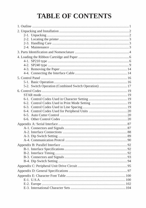
TABLE OF CONTENTS1. Outline ...............................................................................................................12. Unpacking and Installation ................................................................................2
2-1. Unpacking ..............................................................................................22-2. Locating the printer ................................................................................32-3. Handling Care ........................................................................................32-4. Maintenance ...........................................................................................3
3. Parts Identification and Nomenclature ..............................................................4
4. Loading the Ribbon Cartridge and Paper ..........................................................64-1. SP210 type .............................................................................................64-2. SP240 type .............................................................................................94-3. Removing the Paper .............................................................................144-4. Connecting the Interface Cable ............................................................14
5. Control Panel ...................................................................................................165-1. Basic Operation ....................................................................................165-2. Switch Operation (Combined Switch Operation) ................................17
6. Control Codes ..................................................................................................19STAR mode ..................................................................................................196-1. Control Codes Used in Character Setting ............................................196-2. Control Codes Used in Print Mode Setting .........................................196-3. Control Codes Used in Line Spacing ...................................................196-4. Control Codes Used for Peripheral Units ............................................206-5. Auto Cutter Control .............................................................................206-6. Other Control Codes ............................................................................20
Appendix A: Serial Interface ...............................................................................87A-1. Connectors and Signals ........................................................................87A-2. Interface Connections ..........................................................................88A-3. Dip Switch Setting ...............................................................................89A-4. Communication Protcol .......................................................................90
Appendix B: Parallel Interface ............................................................................92B-1. Interface Specifications ........................................................................92B-2. Interface Timing...................................................................................92B-3. Connectors and Signals ........................................................................93B-4. Dip Switch Setting ...............................................................................94
Appendix C: Peripheral Unit Drive Circuit .........................................................95Appendix D: General Specifications ...................................................................97
Appendix E: Character Font Table ....................................................................100E-1. U.S.A. ................................................................................................100E-2. Europe ................................................................................................102E-3. International Character Sets ...............................................................104
– 1 –
EN
GLIS
H
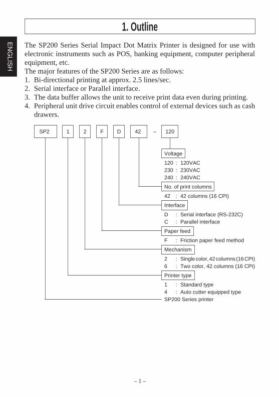
The SP200 Series Serial Impact Dot Matrix Printer is designed for use withelectronic instruments such as POS, banking equipment, computer peripheralequipment, etc.The major features of the SP200 Series are as follows:1. Bi-directional printing at approx. 2.5 lines/sec.2. Serial interface or Parallel interface.3. The data buffer allows the unit to receive print data even during printing.4. Peripheral unit drive circuit enables control of external devices such as cash
drawers.
SP2 1 2 F D 42 – 120
Voltage
120 : 120VAC230 : 230VAC240 : 240VAC
No. of print columns
42 : 42 columns (16 CPI)
Interface
D : Serial interface (RS-232C)C : Parallel interface
Paper feed
F : Friction paper feed method
Mechanism
2 : Single color, 42 columns (16 CPI)6 : Two color, 42 columns (16 CPI)
Printer type
1 : Standard type4 : Auto cutter equipped typeSP200 Series printer
1. Outline
– 2 –
EN
GLI
SH
2. Unpacking and Installation2-1. Unpacking
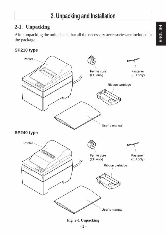
After unpacking the unit, check that all the necessary accessories are included inthe package.
SP210 type
SP240 type
Fig. 2-1 Unpacking
User´s manual
Ribbon cartridge
Printer
Ferrite core(EU only)
Fastener(EU only)
Printer
User´s manual
Ribbon cartridge
Ferrite core(EU only)
Fastener(EU only)
– 3 –
EN
GLIS
H
2-2. Locating the printer
When you locate your printer, keep the following tips in mind:1. Protect your printer from excessive heat such as direct sunlight or heaters, and
keep it away from moisture and dust.2. Place the printer on a firm, level surface which is fairly vibration-free.3. A steady power supply that is not subject to power surges should be connected
to the printer.For example, do not connect it to the same circuit as a large, noise-producingappliance such as a refrigerator or an air conditioner.
4. Make sure the line voltage is the voltage specified on the printer’s identifica-tion plate.
5. To disconnect the printer, the plug has to be disconnected from the wall socket,which has to be located close to the printer, and easy to access.
2-3. Handling Care
1. Be careful not to drop paper clips, pins or other foreign matter into the unit asthese cause the printer to malfunction.
2. Do not attempt to print when either paper or ribbon cartridge is not located inthe printer, otherwise the print head can be damaged.
3. Do not open the cover while printing.4. Do not touch the print head immediately after printing as it gets very hot.5. Use only roll paper that is not glued to the core.6. When the paper end mark appears on the paper, replace the roll paper before
it runs out.
2-4. Maintenance
Essentially, your printer is a robust piece of equipment, but should be treated witha modicum of care in order to avoid malfunctions. For example:1. Keep your printer in a “comfortable” environment. Roughly speaking, if you
feel comfortable, then the environment is suitable for your printer.2. Do not subject the printer to physical shocks or excessive vibration.3. Avoid over-dusty environments. Dust is the enemy of all precision mechani-
cal devices.4. To clean the exterior of the printer, use a cloth barely dampened with either
water with a little detergent or a little alcohol, but do not allow any liquid tofall inside the printer.
5. The interior of the printer may be cleaned with a small cleaner or a com-pressed-air aerosol (sold for this purpose). When performing this operation,be sure not to bend or damage any cable connections or electronic compo-nents.
– 4 –
EN
GLI
SH
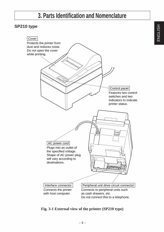
3. Parts Identification and NomenclatureSP210 type
Fig. 3-1 External view of the printer (SP210 type)
Features two controlswitches and twoindicators to indicateprinter status.
Control panel
Protects the printer from dust and reduces noise.Do not open the coverwhile printing.
Cover
Connects the printerwith host computer.
Interface connectorConnects to peripheral units suchas cash drawers, etc.Do not connect this to a telephone.
Peripheral unit drive circuit connector
Plugs into an outlet ofthe specified voltage.Shape of AC power plugwill vary according todestinations.
AC power cord
– 5 –
EN
GLIS
H
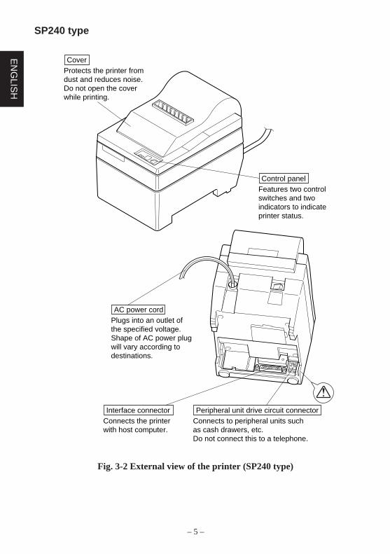
SP240 type
Fig. 3-2 External view of the printer (SP240 type)
Features two controlswitches and twoindicators to indicateprinter status.
Control panel
Connects the printerwith host computer.
Interface connectorConnects to peripheral units suchas cash drawers, etc.Do not connect this to a telephone.
Peripheral unit drive circuit connector
Protects the printer from dust and reduces noise.Do not open the coverwhile printing.
Cover
Plugs into an outlet ofthe specified voltage.Shape of AC power plugwill vary according todestinations.
AC power cord
– 6 –
EN
GLI
SH
4. Loading the Ribbon Cartridge and Paper4-1. SP210 type
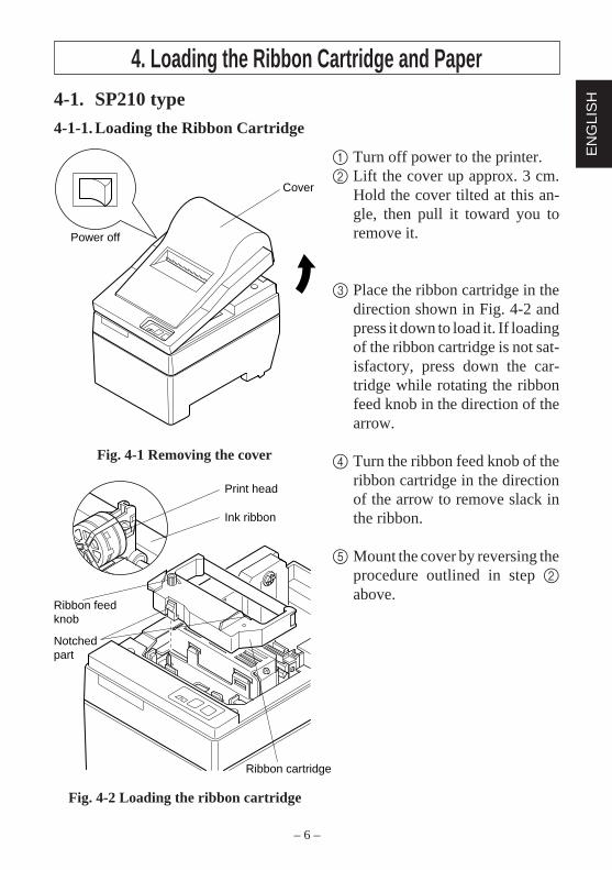
4-1-1. Loading the Ribbon Cartridge
1 Turn off power to the printer.2 Lift the cover up approx. 3 cm.
Hold the cover tilted at this an-gle, then pull it toward you toremove it.
3 Place the ribbon cartridge in thedirection shown in Fig. 4-2 andpress it down to load it. If loadingof the ribbon cartridge is not sat-isfactory, press down the car-tridge while rotating the ribbonfeed knob in the direction of thearrow.
4 Turn the ribbon feed knob of theribbon cartridge in the directionof the arrow to remove slack inthe ribbon.
5 Mount the cover by reversing theprocedure outlined in step 2above.
Fig. 4-1 Removing the cover
Cover
Power off
Print head
Ink ribbon
Ribbon cartridge
Ribbon feedknob
Notchedpart
Fig. 4-2 Loading the ribbon cartridge
– 7 –
EN
GLIS
H
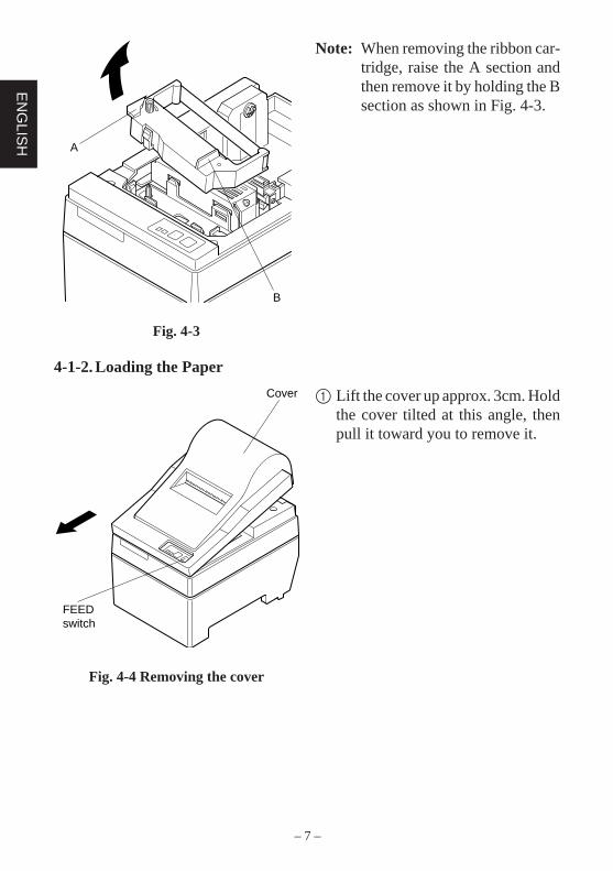
Note: When removing the ribbon car-tridge, raise the A section andthen remove it by holding the Bsection as shown in Fig. 4-3.
A
B
Fig. 4-3
4-1-2. Loading the Paper
1 Lift the cover up approx. 3cm. Holdthe cover tilted at this angle, thenpull it toward you to remove it.
Cover
FEEDswitch
Fig. 4-4 Removing the cover
– 8 –
EN
GLI
SH
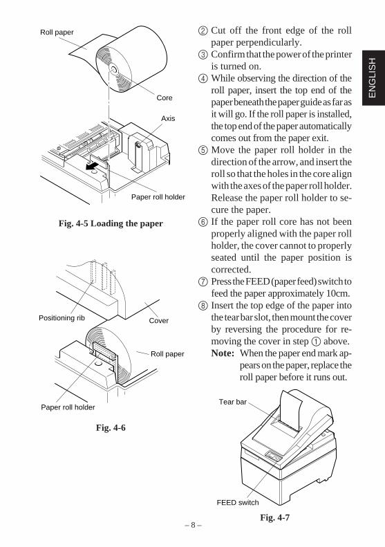
2 Cut off the front edge of the rollpaper perpendicularly.
3 Confirm that the power of the printeris turned on.
4 While observing the direction of theroll paper, insert the top end of thepaper beneath the paper guide as far asit will go. If the roll paper is installed,the top end of the paper automaticallycomes out from the paper exit.
5 Move the paper roll holder in thedirection of the arrow, and insert theroll so that the holes in the core alignwith the axes of the paper roll holder.Release the paper roll holder to se-cure the paper.
6 If the paper roll core has not beenproperly aligned with the paper rollholder, the cover cannot to properlyseated until the paper position iscorrected.
7 Press the FEED (paper feed) switch tofeed the paper approximately 10cm.
8 Insert the top edge of the paper intothe tear bar slot, then mount the coverby reversing the procedure for re-moving the cover in step 1 above.Note: When the paper end mark ap-
pears on the paper, replace theroll paper before it runs out.
Fig. 4-7
Positioning rib Cover
Roll paper
Paper roll holder
Roll paper
Core
Axis
Paper roll holder
Fig. 4-5 Loading the paper
Fig. 4-6
FEED switch
Tear bar
– 9 –
EN
GLIS
H
4-2. SP240 type
4-2-1. Loading the Ribbon Cartridge
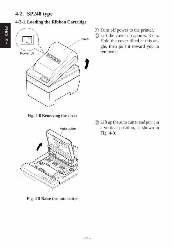
1 Turn off power to the printer.2 Lift the cover up approx. 3 cm.
Hold the cover tilted at this an-gle, then pull it toward you toremove it.
3 Lift up the auto cutter and put it ina vertical position, as shown inFig. 4-9.
Cover
Power off
Fig. 4-8 Removing the cover
Auto cutter
Fig. 4-9 Raise the auto cutter
– 10 –
EN
GLI
SH
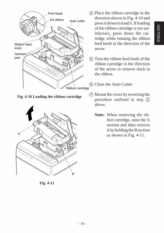
4 Place the ribbon cartridge in thedirection shown in Fig. 4-10 andpress it down to load it. If loadingof the ribbon cartridge is not sat-isfactory, press down the car-tridge while rotating the ribbonfeed knob in the direction of thearrow.
5 Turn the ribbon feed knob of theribbon cartridge in the directionof the arrow to remove slack inthe ribbon.
6 Close the Auto Cutter.
7 Mount the cover by reversing theprocedure outlined in step 2above.
Note: When removing the rib-bon cartridge, raise the Asection and then removeit by holding the B sectionas shown in Fig. 4-11.
Fig. 4-10 Loading the ribbon cartridge
Print head
Ink ribbon Auto cutter
Ribbon cartridge
Ribbon feedknob
Notchedpart
A
B
Fig. 4-11
– 11 –
EN
GLIS
H
4-2-2. Loading the Paper
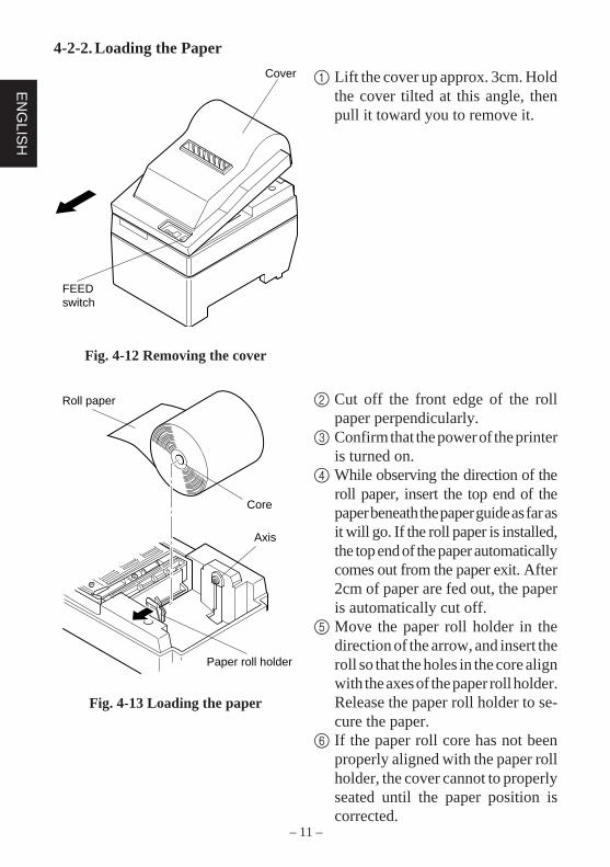
1 Lift the cover up approx. 3cm. Holdthe cover tilted at this angle, thenpull it toward you to remove it.
2 Cut off the front edge of the rollpaper perpendicularly.
3 Confirm that the power of the printeris turned on.
4 While observing the direction of theroll paper, insert the top end of thepaper beneath the paper guide as far asit will go. If the roll paper is installed,the top end of the paper automaticallycomes out from the paper exit. After2cm of paper are fed out, the paperis automatically cut off.
5 Move the paper roll holder in thedirection of the arrow, and insert theroll so that the holes in the core alignwith the axes of the paper roll holder.Release the paper roll holder to se-cure the paper.
6 If the paper roll core has not beenproperly aligned with the paper rollholder, the cover cannot to properlyseated until the paper position iscorrected.
Cover
FEEDswitch
Fig. 4-12 Removing the cover
Roll paper
Core
Axis
Paper roll holder
Fig. 4-13 Loading the paper
– 12 –
EN
GLI
SH
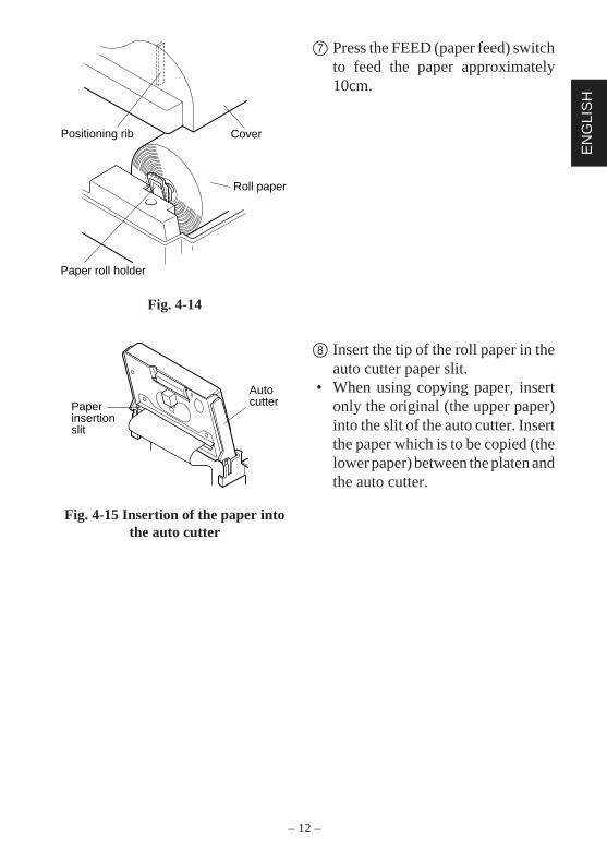
7 Press the FEED (paper feed) switchto feed the paper approximately10cm.
8 Insert the tip of the roll paper in theauto cutter paper slit.
• When using copying paper, insertonly the original (the upper paper)into the slit of the auto cutter. Insertthe paper which is to be copied (thelower paper) between the platen andthe auto cutter.
Fig. 4-14
Positioning rib Cover
Roll paper
Paper roll holder
Paperinsertionslit
Autocutter
Fig. 4-15 Insertion of the paper intothe auto cutter
– 13 –
EN
GLIS
H
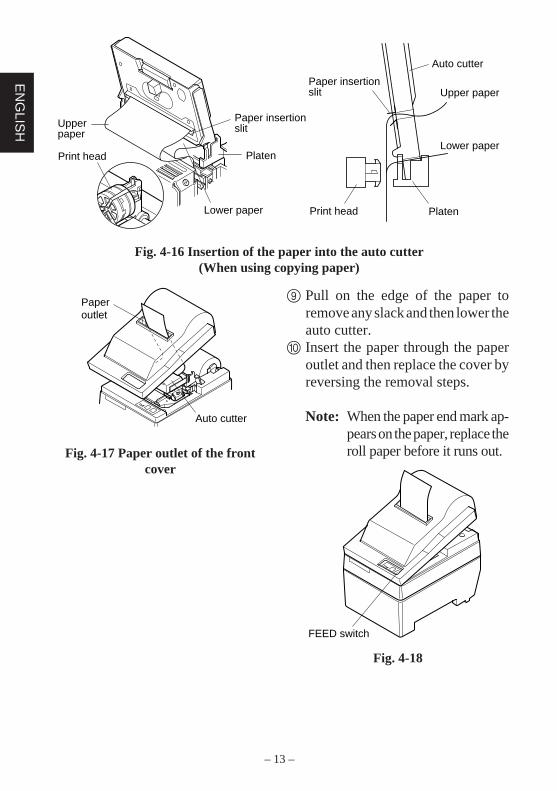
Fig. 4-16 Insertion of the paper into the auto cutter(When using copying paper)
9 Pull on the edge of the paper toremove any slack and then lower theauto cutter.
0 Insert the paper through the paperoutlet and then replace the cover byreversing the removal steps.
Note: When the paper end mark ap-pears on the paper, replace theroll paper before it runs out.
Fig. 4-18
Paperoutlet
Auto cutter
Fig. 4-17 Paper outlet of the frontcover
Paper insertion slit
Platen
Lower paper
Upper paper
Print head
Print head
Paper insertion slit
Auto cutter
Platen
Lower paper
Upper paper
FEED switch
– 14 –
EN
GLI
SH
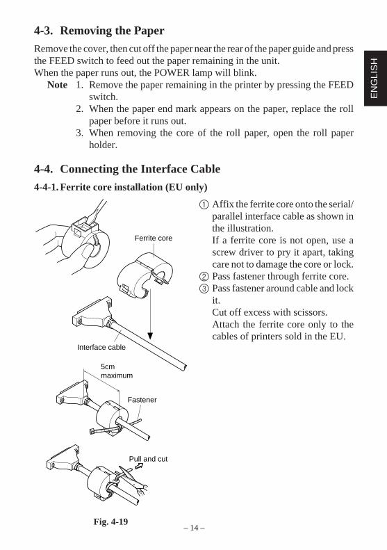
4-3. Removing the Paper
Remove the cover, then cut off the paper near the rear of the paper guide and pressthe FEED switch to feed out the paper remaining in the unit.When the paper runs out, the POWER lamp will blink.
Note 1. Remove the paper remaining in the printer by pressing the FEEDswitch.
2. When the paper end mark appears on the paper, replace the rollpaper before it runs out.
3. When removing the core of the roll paper, open the roll paperholder.
4-4. Connecting the Interface Cable
4-4-1. Ferrite core installation (EU only)
1 Affix the ferrite core onto the serial/parallel interface cable as shown inthe illustration.If a ferrite core is not open, use ascrew driver to pry it apart, takingcare not to damage the core or lock.
2 Pass fastener through ferrite core.3 Pass fastener around cable and lock
it.Cut off excess with scissors.Attach the ferrite core only to thecables of printers sold in the EU.
Ferrite core
Interface cable
Fig. 4-19
Pull and cut
5cm maximum
Fastener
– 15 –
EN
GLIS
H
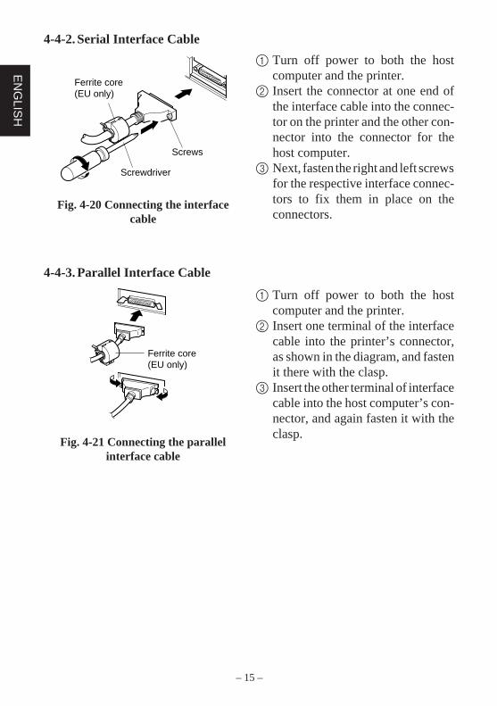
4-4-2. Serial Interface Cable
1 Turn off power to both the hostcomputer and the printer.
2 Insert the connector at one end ofthe interface cable into the connec-tor on the printer and the other con-nector into the connector for thehost computer.
3 Next, fasten the right and left screwsfor the respective interface connec-tors to fix them in place on theconnectors.
Ferrite core(EU only)
Screwdriver
Screws
Fig. 4-20 Connecting the interfacecable
4-4-3. Parallel Interface Cable
1 Turn off power to both the hostcomputer and the printer.
2 Insert one terminal of the interfacecable into the printer’s connector,as shown in the diagram, and fastenit there with the clasp.
3 Insert the other terminal of interfacecable into the host computer’s con-nector, and again fasten it with theclasp.
Fig. 4-21 Connecting the parallelinterface cable
Ferrite core(EU only)
– 16 –
EN
GLI
SH
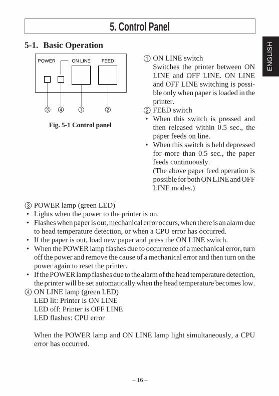
5. Control Panel5-1. Basic Operation
1 ON LINE switchSwitches the printer between ONLINE and OFF LINE. ON LINEand OFF LINE switching is possi-ble only when paper is loaded in theprinter.
2 FEED switch• When this switch is pressed and
then released within 0.5 sec., thepaper feeds on line.
• When this switch is held depressedfor more than 0.5 sec., the paperfeeds continuously.(The above paper feed operation ispossible for both ON LINE and OFFLINE modes.)
3 POWER lamp (green LED)• Lights when the power to the printer is on.• Flashes when paper is out, mechanical error occurs, when there is an alarm due
to head temperature detection, or when a CPU error has occurred.• If the paper is out, load new paper and press the ON LINE switch.• When the POWER lamp flashes due to occurrence of a mechanical error, turn
off the power and remove the cause of a mechanical error and then turn on thepower again to reset the printer.
• If the POWER lamp flashes due to the alarm of the head temperature detection,the printer will be set automatically when the head temperature becomes low.
4 ON LINE lamp (green LED)LED lit: Printer is ON LINELED off: Printer is OFF LINELED flashes: CPU error
When the POWER lamp and ON LINE lamp light simultaneously, a CPUerror has occurred.
ON LINEPOWER FEED
3 4 1 2
Fig. 5-1 Control panel
– 17 –
EN
GLIS
H
5-2. Switch Operation (Combined Switch Operation)
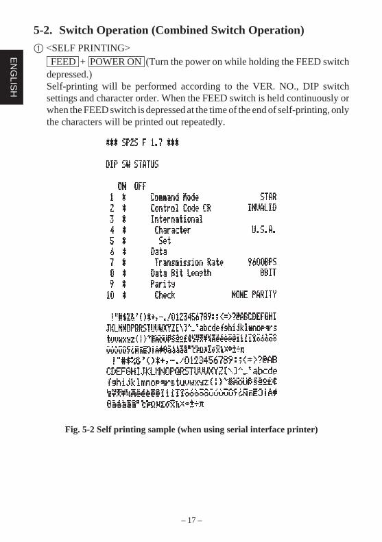
1 <SELF PRINTING> FEED + POWER ON (Turn the power on while holding the FEED switchdepressed.)Self-printing will be performed according to the VER. NO., DIP switchsettings and character order. When the FEED switch is held continuously orwhen the FEED switch is depressed at the time of the end of self-printing, onlythe characters will be printed out repeatedly.
Fig. 5-2 Self printing sample (when using serial interface printer)
– 18 –
EN
GLI
SH
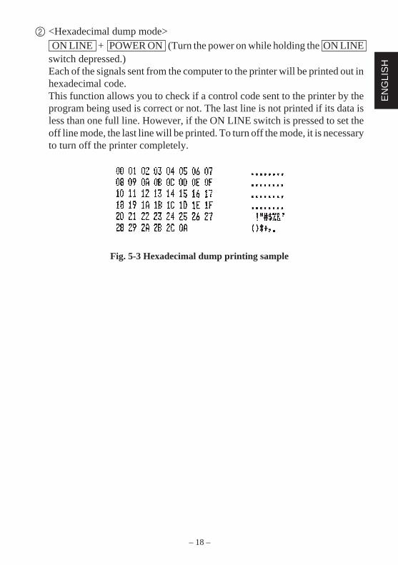
2 <Hexadecimal dump mode> ON LINE + POWER ON (Turn the power on while holding the ON LINEswitch depressed.)Each of the signals sent from the computer to the printer will be printed out inhexadecimal code.This function allows you to check if a control code sent to the printer by theprogram being used is correct or not. The last line is not printed if its data isless than one full line. However, if the ON LINE switch is pressed to set theoff line mode, the last line will be printed. To turn off the mode, it is necessaryto turn off the printer completely.
Fig. 5-3 Hexadecimal dump printing sample
– 19 –
EN
GLIS
H
6. Control CodesSTAR mode
6-1. Control Codes Used in Character Setting
Control codes Hexadecimal codes Function
<ESC> “R” n 1B 52 n Select international character set. Default is accord-ing to the dip switch settings 3, 4 and 5.
<ESC> “M” 1B 4D Select 7 × 7 (Half dots) character size (Defaultsetting)
<ESC> “P” 1B 50 Select 9 × 7 (Half dots) character size
<SO> 0E Select expanded character mode
<SI> 0F Cancel expanded character mode(Default setting)
<DC4> 14 Cancel expanded character mode(Default setting)
<ESC> “W” “1” 1B 57 31 Select expanded character mode<ESC> “W” <1> 1B 57 01
<ESC> “W” “0” 1B 57 30 Cancel expanded character mode<ESC> “W” <0> 1B 57 00 (Default setting)
6-2. Control Codes Used in Print Mode Setting
Control codes Hexadecimal codes Function
<ESC> “4” 1B 34 Red color print selection (enable for SP216)
<ESC> “5” 1B 35 Red color print deselection (enable for SP216) (De-fault setting)
<ESC> “E” 1B 45 Emphasized print mode selection
<ESC> “F” 1B 46 Emphasized print mode deselection (Default set-ting)
6-3. Control Codes Used in Line Spacing
Control codes Hexadecimal codes Function
<LF> 0A Line feed
<CR> 0D Line feed (same as LF)
<ESC> “a” n 1B 61 n Feed paper n lines
– 20 –
EN
GLI
SH
6-4. Control Codes Used for Peripheral Units
Control codes Hexadecimal codes Function
<ESC> <BEL> n1 n2 1B 07 n1 n2 Adjust drive pulse width for peripheral unit (Defaultsetting)
<BEL> 07 Deferred drive command “A” for peripheral unit 1
<FS> 1C Immediate drive command “B” for peripheral unit 1
6-5. Auto Cutter Control (SP240 type only)
Control codes Hexadecimal codes Function
<ESC> “d” “0” 1B 64 30 Full-cut command to the auto cutter<ESC> “d” <0> 1B 64 00
<ESC> “d” “1” 1B 64 31 Partial-cut command to the auto cutter<ESC> “d” <1> 1B 64 01
6-6. Other Control Codes
Control codes Hexadecimal codes Function
<CAN> 18 Cancel print data in buffer
<ESC> “@” 1B 40 Initialize printer
<ESC> “e” “0” 1B 65 30 ON LINE/FEED switch valid<ESC> “e” <0> 1B 65 00 (Default setting)
<ESC> “e” “1” 1B 65 31 ON LINE/FEED switch invalid<ESC> “e” <1> 1B 65 01
<ESC> “f” “0” 1B 66 30 ON LINE switch valid<ESC> “f” <0> 1B 66 00 (Default setting)
<ESC> “f” “1” 1B 66 31 ON LINE switch invalid<ESC> “f” <1> 1B 66 01

– 21 –
EN
GLIS
H
– 22 –
FR
AN
ÇA
IS
TABLE DES MATIERES1. Introduction .....................................................................................................23
2. Déballage et Inspection ...................................................................................242-1. Déballage .............................................................................................242-2. Emplacement de l’imprimante .............................................................252-3. Précautions de manipulation ................................................................252-4. Entretien ...............................................................................................25
3. Identification des Pièces et Nomenclature ......................................................264. Installation d’une cartouche à ruban et chargement du papier ........................28
4-1. Modèle SP210 ......................................................................................284-2. Modèle SP240 ......................................................................................314-3. Enlèvement d’un rouleau de papier .....................................................364-4. Connexion du câble d’interface ...........................................................36
5. Panneau de Commande ...................................................................................385-1. Fonctionnement de base.......................................................................385-2. Utilisation des touches (Utilisation combinée des touches) ................39
6. Codes de contrôle ............................................................................................41Mode STAR .................................................................................................416-1. Commandes utilisées pour le réglage des caractères ...........................416-2. Commandes utilisées pour le réglage du mode d’impression ..............416-3. Commandes utilisées pour l’espacement des lignes ............................416-4. Commandes utilisées pour le pilotage des appareils périphériques .....426-5. Commandes de pilotage de l’unité de découpage automatique
(Modèle SP240 seulement) ..................................................................426-6. Autres commandes ...............................................................................42
APPENDICE .......................................................................................................87
L’appendice n’est pas traduit.
– 23 –
FR
AN
ÇA
IS
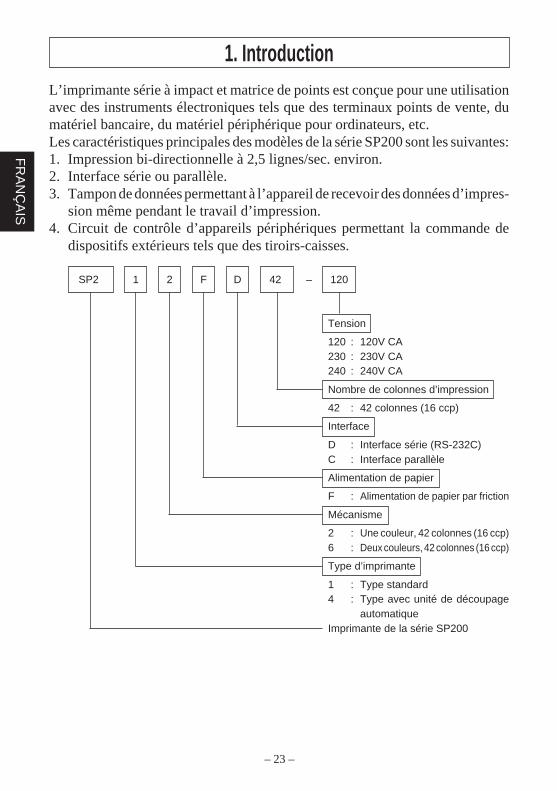
L’imprimante série à impact et matrice de points est conçue pour une utilisationavec des instruments électroniques tels que des terminaux points de vente, dumatériel bancaire, du matériel périphérique pour ordinateurs, etc.Les caractéristiques principales des modèles de la série SP200 sont les suivantes:1. Impression bi-directionnelle à 2,5 lignes/sec. environ.2. Interface série ou parallèle.3. Tampon de données permettant à l’appareil de recevoir des données d’impres-
sion même pendant le travail d’impression.4. Circuit de contrôle d’appareils périphériques permettant la commande de
dispositifs extérieurs tels que des tiroirs-caisses.
SP2 1 2 F D 42 – 120
Tension
120 : 120V CA230 : 230V CA240 : 240V CA
Nombre de colonnes d’impression
42 : 42 colonnes (16 ccp)
Interface
D : Interface série (RS-232C)C : Interface parallèle
Alimentation de papier
F : Alimentation de papier par friction
Mécanisme
2 : Une couleur, 42 colonnes (16 ccp)6 : Deux couleurs, 42 colonnes (16 ccp)
Type d’imprimante
1 : Type standard4 : Type avec unité de découpage
automatiqueImprimante de la série SP200
1. Introduction
– 24 –
FR
AN
ÇA
IS
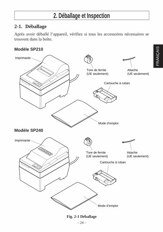
Mode d’emploi
Cartouche à ruban
Imprimante
Tore de ferrite (UE seulement)
Attache(UE seulement)
Imprimante
Mode d’emploi
Cartouche à ruban
Tore de ferrite (UE seulement)
Attache(UE seulement)
2. Déballage et Inspection2-1. Déballage
Après avoir déballé l’appareil, vérifiez si tous les accessoires nécessaires setrouvent dans la boîte.
Modèle SP210
Modèle SP240
Fig. 2-1 Déballage
– 25 –
FR
AN
ÇA
IS
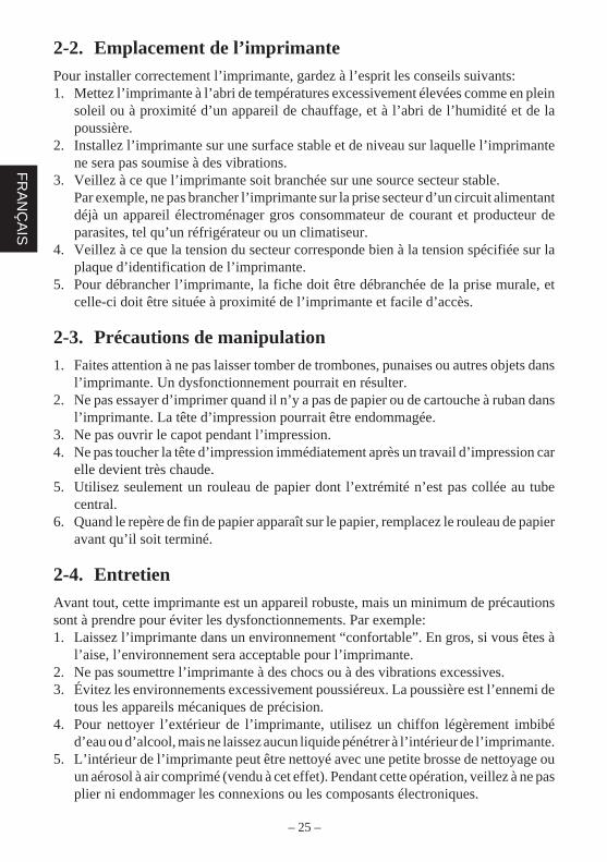
2-2. Emplacement de l’imprimantePour installer correctement l’imprimante, gardez à l’esprit les conseils suivants:1. Mettez l’imprimante à l’abri de températures excessivement élevées comme en plein
soleil ou à proximité d’un appareil de chauffage, et à l’abri de l’humidité et de lapoussière.
2. Installez l’imprimante sur une surface stable et de niveau sur laquelle l’imprimantene sera pas soumise à des vibrations.
3. Veillez à ce que l’imprimante soit branchée sur une source secteur stable.Par exemple, ne pas brancher l’imprimante sur la prise secteur d’un circuit alimentantdéjà un appareil électroménager gros consommateur de courant et producteur deparasites, tel qu’un réfrigérateur ou un climatiseur.
4. Veillez à ce que la tension du secteur corresponde bien à la tension spécifiée sur laplaque d’identification de l’imprimante.
5. Pour débrancher l’imprimante, la fiche doit être débranchée de la prise murale, etcelle-ci doit être située à proximité de l’imprimante et facile d’accès.
2-3. Précautions de manipulation1. Faites attention à ne pas laisser tomber de trombones, punaises ou autres objets dans
l’imprimante. Un dysfonctionnement pourrait en résulter.2. Ne pas essayer d’imprimer quand il n’y a pas de papier ou de cartouche à ruban dans
l’imprimante. La tête d’impression pourrait être endommagée.3. Ne pas ouvrir le capot pendant l’impression.4. Ne pas toucher la tête d’impression immédiatement après un travail d’impression car
elle devient très chaude.5. Utilisez seulement un rouleau de papier dont l’extrémité n’est pas collée au tube
central.6. Quand le repère de fin de papier apparaît sur le papier, remplacez le rouleau de papier
avant qu’il soit terminé.
2-4. EntretienAvant tout, cette imprimante est un appareil robuste, mais un minimum de précautionssont à prendre pour éviter les dysfonctionnements. Par exemple:1. Laissez l’imprimante dans un environnement “confortable”. En gros, si vous êtes à
l’aise, l’environnement sera acceptable pour l’imprimante.2. Ne pas soumettre l’imprimante à des chocs ou à des vibrations excessives.3. Évitez les environnements excessivement poussiéreux. La poussière est l’ennemi de
tous les appareils mécaniques de précision.4. Pour nettoyer l’extérieur de l’imprimante, utilisez un chiffon légèrement imbibé
d’eau ou d’alcool, mais ne laissez aucun liquide pénétrer à l’intérieur de l’imprimante.5. L’intérieur de l’imprimante peut être nettoyé avec une petite brosse de nettoyage ou
un aérosol à air comprimé (vendu à cet effet). Pendant cette opération, veillez à ne pasplier ni endommager les connexions ou les composants électroniques.
– 26 –
FR
AN
ÇA
IS
3. Identification des Pièces et NomenclatureModèle SP210
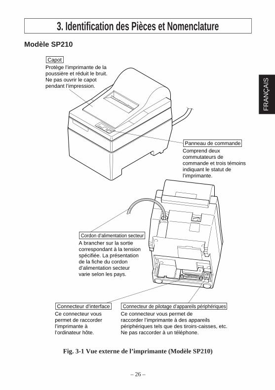
Fig. 3-1 Vue externe de l’imprimante (Modèle SP210)
Comprend deux commutateurs de commande et trois témoins indiquant le statut de l’imprimante.
Panneau de commande
Protège l’imprimante de la poussière et réduit le bruit. Ne pas ouvrir le capot pendant l’impression.
Capot
Ce connecteur vous permet de raccorder l’imprimante à l’ordinateur hôte.
Connecteur d’interfaceCe connecteur vous permet de raccorder l’imprimante à des appareils périphériques tels que des tiroirs-caisses, etc.Ne pas raccorder à un téléphone.
Connecteur de pilotage d’appareils périphériques
A brancher sur la sortie correspondant à la tension spécifiée. La présentation de la fiche du cordon d’alimentation secteur varie selon les pays.
Cordon d’alimentation secteur

– 27 –
FR
AN
ÇA
IS
Modèle SP240
Fig. 3-2 Vue externe de l’imprimante (Modèle SP240)
Comprend deux commutateurs de commande et deux témoins indiquant le statut de l’imprimante.
Panneau de commande
Ce connecteur vous permet de raccorder l’imprimante à l’ordinateur hôte.
Connecteur d’interfaceCe connecteur vous permet de raccorder l’imprimante à des appareils périphériques tels que des tiroirs-caisses, etc.Ne pas raccorder à un téléphone.
Connecteur de pilotage d’appareils périphériques
Protège l’imprimante de la poussière et réduit le bruit. Ne pas ouvrir le capot pendant l’impression.
Capot
A brancher sur la sortie correspondant à la tension spécifiée. La présentation de la fiche du cordon d’alimentation secteur varie selon les pays.
Cordon d’alimentation secteur
– 28 –
FR
AN
ÇA
IS
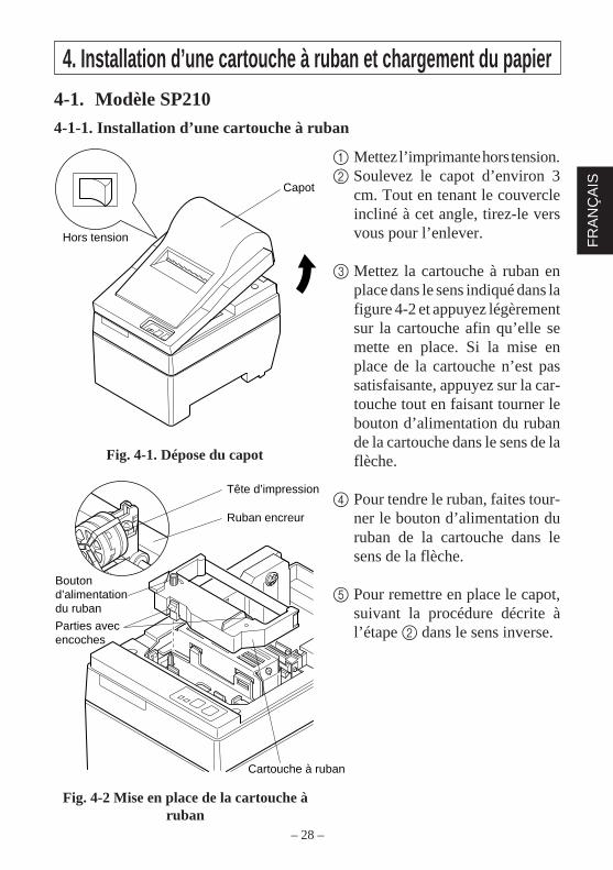
Tête d’impression
Ruban encreur
Cartouche à ruban
Bouton d’alimentation du ruban
Parties avec encoches
Capot
Hors tension
4. Installation d’une cartouche à ruban et chargement du papier4-1. Modèle SP210
4-1-1. Installation d’une cartouche à ruban
1 Mettez l’imprimante hors tension.2 Soulevez le capot d’environ 3
cm. Tout en tenant le couvercleincliné à cet angle, tirez-le versvous pour l’enlever.
3 Mettez la cartouche à ruban enplace dans le sens indiqué dans lafigure 4-2 et appuyez légèrementsur la cartouche afin qu’elle semette en place. Si la mise enplace de la cartouche n’est passatisfaisante, appuyez sur la car-touche tout en faisant tourner lebouton d’alimentation du rubande la cartouche dans le sens de laflèche.
4 Pour tendre le ruban, faites tour-ner le bouton d’alimentation duruban de la cartouche dans lesens de la flèche.
5 Pour remettre en place le capot,suivant la procédure décrite àl’étape 2 dans le sens inverse.
Fig. 4-1. Dépose du capot
Fig. 4-2 Mise en place de la cartouche àruban
– 29 –
FR
AN
ÇA
IS
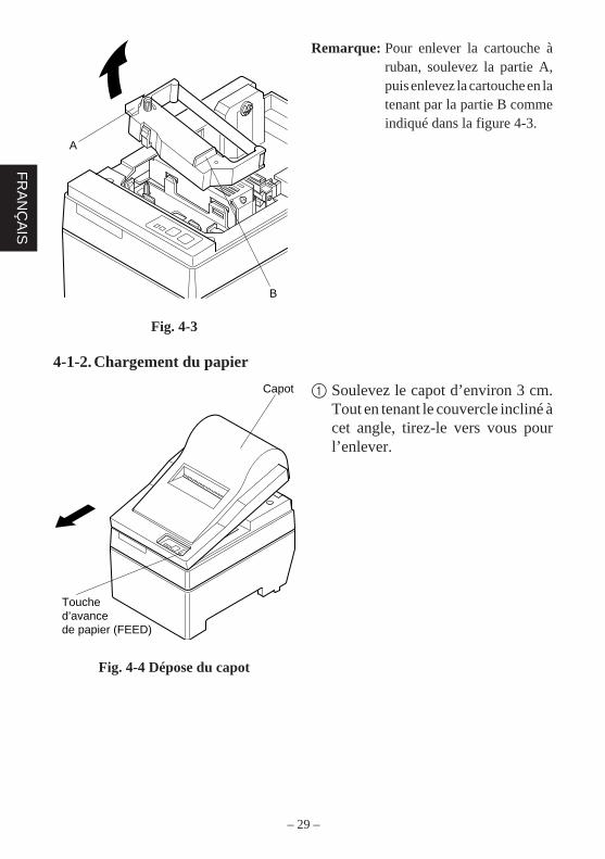
Capot
Touche d’avance de papier (FEED)
Remarque: Pour enlever la cartouche àruban, soulevez la partie A,puis enlevez la cartouche en latenant par la partie B commeindiqué dans la figure 4-3.
A
B
Fig. 4-3
4-1-2. Chargement du papier
1 Soulevez le capot d’environ 3 cm.Tout en tenant le couvercle incliné àcet angle, tirez-le vers vous pourl’enlever.
Fig. 4-4 Dépose du capot
– 30 –
FR
AN
ÇA
IS
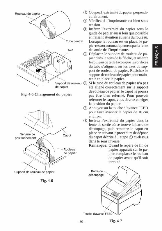
Touche d’avance FEED
Barre de découpage
Nervure de positionnement
Capot
Rouleau de papier
Support de rouleau de papier
Rouleau de papier
Tube central
Axe
Support de rouleau de papier
2 Coupez l’extrémité du papier perpendi-culairement.
3 Vérifiez si l’imprimante est bien soustension.
4 Insérez l’extrémité du papier sous leguide de papier aussi loin que possibleen faisant attention au sens du rouleau.Lorsque le rouleau est en place, le pa-pier ressort automatiquement par la fentede sortie de l’imprimante.
5 Déplacez le support de rouleau de pa-pier dans le sens de la flèche, et insérezle rouleau de telle façon que les orificesdu tube s’alignent sur les axes du sup-port de rouleau de papier. Relâchez lesupport de rouleau de papier pour main-tenir en place le papier.
6 Si le tube du rouleau de papier n’a pasété aligné correctement sur le supportde rouleau de papier, le capot ne pourrapas être bien refermé. Pour pouvoirrefermer le capot, vous devrez corrigerla position du papier.
7 Appuyez sur la touche d’avance FEEDpour faire avancer le papier de 10 cmenviron.
8 Insérez l’extrémité du papier dans lafente de sortie où se trouve la barre dedécoupage, puis remettez le capot enplace en suivant la procédure de déposedu capot décrite à l’étape 1 ci-dessusdans le sens inverse.Remarque: Quand le repère de fin de
papier apparaît sur le pa-pier, remplacez le rouleaude papier avant qu’il soitterminé.
Fig. 4-7
Fig. 4-5 Chargement du papier
Fig. 4-6
– 31 –
FR
AN
ÇA
IS
Unité de découpage automatique
Capot
Hors tension
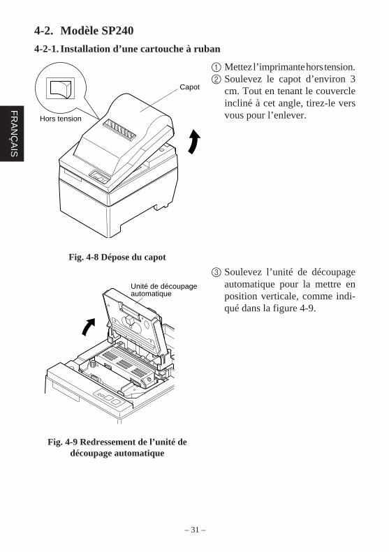
4-2. Modèle SP240
4-2-1. Installation d’une cartouche à ruban
1 Mettez l’imprimante hors tension.2 Soulevez le capot d’environ 3
cm. Tout en tenant le couvercleincliné à cet angle, tirez-le versvous pour l’enlever.
3 Soulevez l’unité de découpageautomatique pour la mettre enposition verticale, comme indi-qué dans la figure 4-9.
Fig. 4-8 Dépose du capot
Fig. 4-9 Redressement de l’unité dedécoupage automatique
– 32 –
FR
AN
ÇA
IS
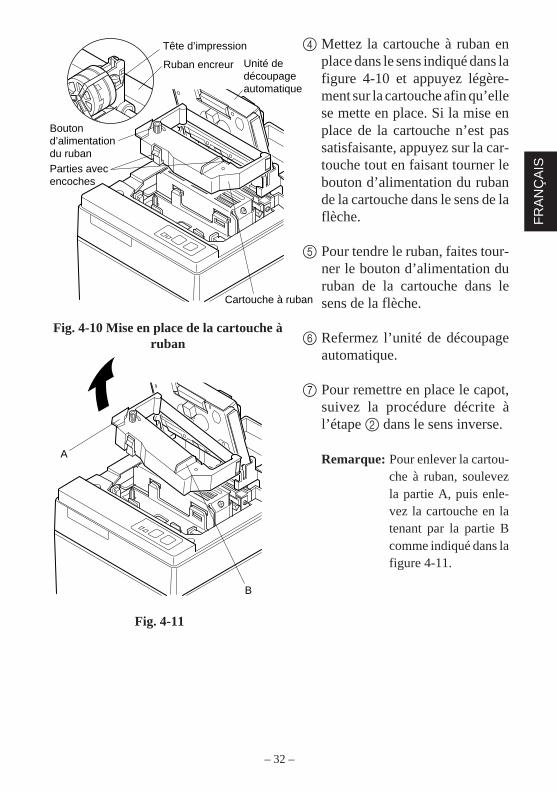
Tête d’impression
Ruban encreur Unité de découpage automatique
Cartouche à ruban
Bouton d’alimentation du rubanParties avec encoches
4 Mettez la cartouche à ruban enplace dans le sens indiqué dans lafigure 4-10 et appuyez légère-ment sur la cartouche afin qu’ellese mette en place. Si la mise enplace de la cartouche n’est passatisfaisante, appuyez sur la car-touche tout en faisant tourner lebouton d’alimentation du rubande la cartouche dans le sens de laflèche.
5 Pour tendre le ruban, faites tour-ner le bouton d’alimentation duruban de la cartouche dans lesens de la flèche.
6 Refermez l’unité de découpageautomatique.
7 Pour remettre en place le capot,suivez la procédure décrite àl’étape 2 dans le sens inverse.
Remarque: Pour enlever la cartou-che à ruban, soulevezla partie A, puis enle-vez la cartouche en latenant par la partie Bcomme indiqué dans lafigure 4-11.
A
B
Fig. 4-11
Fig. 4-10 Mise en place de la cartouche àruban
– 33 –
FR
AN
ÇA
IS
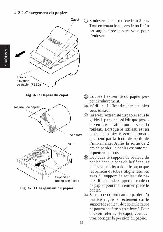
Rouleau de papier
Tube central
Axe
Support de rouleau de papier
Capot
Touche d’avance de papier (FEED)
4-2-2. Chargement du papier
1 Soulevez le capot d’environ 3 cm.Tout en tenant le couvercle incliné àcet angle, tirez-le vers vous pourl’enlever.
2 Coupez l’extrémité du papier per-pendiculairement.
3 Vérifiez si l’imprimante est biensous tension.
4 Insérez l’extrémité du papier sous leguide de papier aussi loin que possi-ble en faisant attention au sens durouleau. Lorsque le rouleau est enplace, le papier ressort automati-quement par la fente de sortie del’imprimante. Après la sortie de 2cm de papier, le papier est automa-tiquement coupé.
5 Déplacez le support de rouleau depapier dans le sens de la flèche, etinsérez le rouleau de telle façon queles orifices du tube s’alignent sur lesaxes du support de rouleau de pa-pier. Relâchez le support de rouleaude papier pour maintenir en place lepapier.
6 Si le tube du rouleau de papier n’apas été aligné correctement sur lesupport de rouleau de papier, le capotne pourra pas être bien refermé. Pourpouvoir refermer le capot, vous de-vrez corriger la position du papier.
Fig. 4-12 Dépose du capot
Fig. 4-13 Chargement du papier
– 34 –
FR
AN
ÇA
IS
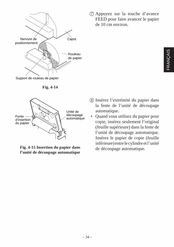
Fente d’insertion du papier
Unité de découpage automatique
Nervure de positionnement
Capot
Rouleau de papier
Support de rouleau de papier
7 Appuyez sur la touche d’avanceFEED pour faire avancer le papierde 10 cm environ.
8 Insérez l’extrémité du papier dansla fente de l’unité de découpageautomatique.
• Quand vous utilisez du papier pourcopie, insérez seulement l’original(feuille supérieure) dans la fente del’unité de découpage automatique.Insérez le papier de copie (feuilleinférieure) entre le cylindre et l’unitéde découpage automatique.
Fig. 4-14
Fig. 4-15 Insertion du papier dansl’unité de découpage automatique
– 35 –
FR
AN
ÇA
IS
Fente d’insertion du papier
Cylindre
Feuille inférieure
Feuille supérieure
Tête d’impression
Tête d’impression
Fente d’insertion du papier
Unité de découpage automatique
Cylindre
Feuille inférieure
Feuille supérieure
Sortie de papier
Unité de découpage automatique
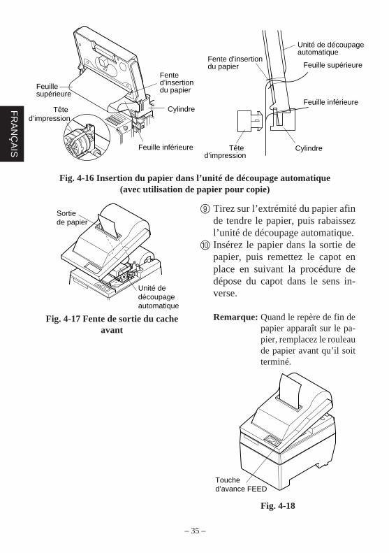
Fig. 4-16 Insertion du papier dans l’unité de découpage automatique(avec utilisation de papier pour copie)
9 Tirez sur l’extrémité du papier afinde tendre le papier, puis rabaissezl’unité de découpage automatique.
0 Insérez le papier dans la sortie depapier, puis remettez le capot enplace en suivant la procédure dedépose du capot dans le sens in-verse.
Remarque: Quand le repère de fin depapier apparaît sur le pa-pier, remplacez le rouleaude papier avant qu’il soitterminé.
Fig. 4-18
Fig. 4-17 Fente de sortie du cacheavant
Touche d’avance FEED
– 36 –
FR
AN
ÇA
IS
Tore de ferrite
Interface câble
Tirer et couper
5 cmmaximum
Attache
4-3. Enlèvement d’un rouleau de papierRetirez le capot, puis coupez le papier juste derrière le guide de papier et appuyezsur la touche d’avance FEED afin de faire sortir le reste du papier qui se trouvetoujours dans l’imprimante.Quand tout le papier est sorti, le témoin POWER clignote.
Remarques 1. Enfoncez la touche d’avance FEED pour retirer le reste du papierqui se trouve dans l’imprimante.
2. N’attendez pas que le rouleau de papier soit épuisé avant de leremplacer. Remplacez-le dès que le repère de fin de rouleauapparaît.
3. Pour enlever le tube du rouleau de papier, ouvrez le support derouleau de papier.
4-4. Connexion du câble d’interface
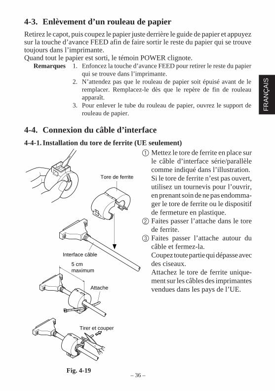
4-4-1. Installation du tore de ferrite (UE seulement)1 Mettez le tore de ferrite en place sur
le câble d’interface série/parallèlecomme indiqué dans l’illustration.Si le tore de ferrite n’est pas ouvert,utilisez un tournevis pour l’ouvrir,en prenant soin de ne pas endomma-ger le tore de ferrite ou le dispositifde fermeture en plastique.
2 Faites passer l’attache dans le torede ferrite.
3 Faites passer l’attache autour ducâble et fermez-la.Coupez toute partie qui dépasse avecdes ciseaux.Attachez le tore de ferrite unique-ment sur les câbles des imprimantesvendues dans les pays de l’UE.
Fig. 4-19
– 37 –
FR
AN
ÇA
IS
Tore de ferrite(UE seulement)
Tore de ferrite(UE seulement)
Tournevis
Vis
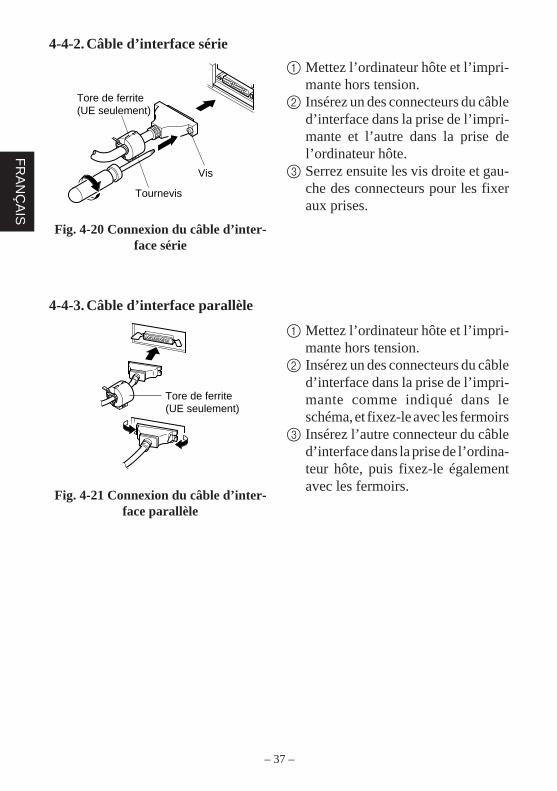
4-4-2. Câble d’interface série
1 Mettez l’ordinateur hôte et l’impri-mante hors tension.
2 Insérez un des connecteurs du câbled’interface dans la prise de l’impri-mante et l’autre dans la prise del’ordinateur hôte.
3 Serrez ensuite les vis droite et gau-che des connecteurs pour les fixeraux prises.
Fig. 4-20 Connexion du câble d’inter-face série
4-4-3. Câble d’interface parallèle
1 Mettez l’ordinateur hôte et l’impri-mante hors tension.
2 Insérez un des connecteurs du câbled’interface dans la prise de l’impri-mante comme indiqué dans leschéma, et fixez-le avec les fermoirs
3 Insérez l’autre connecteur du câbled’interface dans la prise de l’ordina-teur hôte, puis fixez-le égalementavec les fermoirs.
Fig. 4-21 Connexion du câble d’inter-face parallèle
– 38 –
FR
AN
ÇA
IS
5. Panneau de Commande5-1. Fonctionnement de base
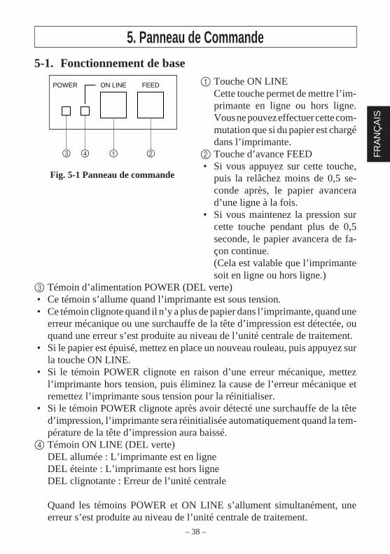
1 Touche ON LINECette touche permet de mettre l’im-primante en ligne ou hors ligne.Vous ne pouvez effectuer cette com-mutation que si du papier est chargédans l’imprimante.
2 Touche d’avance FEED• Si vous appuyez sur cette touche,
puis la relâchez moins de 0,5 se-conde après, le papier avancerad’une ligne à la fois.
• Si vous maintenez la pression surcette touche pendant plus de 0,5seconde, le papier avancera de fa-çon continue.(Cela est valable que l’imprimantesoit en ligne ou hors ligne.)
3 Témoin d’alimentation POWER (DEL verte)• Ce témoin s’allume quand l’imprimante est sous tension.• Ce témoin clignote quand il n’y a plus de papier dans l’imprimante, quand une
erreur mécanique ou une surchauffe de la tête d’impression est détectée, ouquand une erreur s’est produite au niveau de l’unité centrale de traitement.
• Si le papier est épuisé, mettez en place un nouveau rouleau, puis appuyez surla touche ON LINE.
• Si le témoin POWER clignote en raison d’une erreur mécanique, mettezl’imprimante hors tension, puis éliminez la cause de l’erreur mécanique etremettez l’imprimante sous tension pour la réinitialiser.
• Si le témoin POWER clignote après avoir détecté une surchauffe de la têted’impression, l’imprimante sera réinitialisée automatiquement quand la tem-pérature de la tête d’impression aura baissé.
4 Témoin ON LINE (DEL verte)DEL allumée : L’imprimante est en ligneDEL éteinte : L’imprimante est hors ligneDEL clignotante : Erreur de l’unité centrale
Quand les témoins POWER et ON LINE s’allument simultanément, uneerreur s’est produite au niveau de l’unité centrale de traitement.
ON LINEPOWER FEED
3 4 1 2
Fig. 5-1 Panneau de commande
– 39 –
FR
AN
ÇA
IS
5-2. Utilisation des touches (Utilisation combinée des touches)
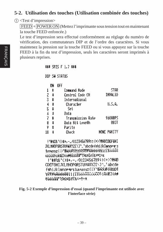
1 <Test d’impression> FEED + POWER ON (Mettez l’imprimante sous tension tout en maintenantla touche FEED enfoncée.)Le test d’impression sera effectué conformément au réglage du numéro devérification, des commutateurs DIP et de l’ordre des caractères. Si vousmaintenez la pression sur la touche FEED ou si vous appuyez sur la toucheFEED à la fin du test d’impression, seuls les caractères seront imprimés àplusieurs reprises.
Fig. 5-2 Exemple d’impression d’essai (quand l’imprimante est utilisée avecl’interface série)
– 40 –
FR
AN
ÇA
IS
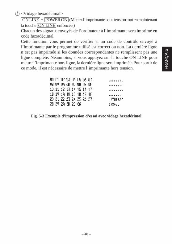
2 <Vidage hexadécimal> ON LINE + POWER ON (Mettez l’imprimante sous tension tout en maintenantla touche ON LINE enfoncée.)Chacun des signaux envoyés de l’ordinateur à l’imprimante sera imprimé encode hexadécimal.Cette fonction vous permet de vérifier si un code de contrôle envoyé àl’imprimante par le programme utilisé est correct ou non. La dernière lignen’est pas imprimée si les données correspondantes ne remplissent pas uneligne complète. Néanmoins, si vous appuyez sur la touche ON LINE pourmettre l’imprimante hors ligne, la dernière ligne sera imprimée. Pour sortir dece mode, il est nécessaire de mettre l’imprimante hors tension.
Fig. 5-3 Exemple d’impression d’essai avec vidage hexadécimal
– 41 –
FR
AN
ÇA
IS
6. Codes de contrôleMode STAR
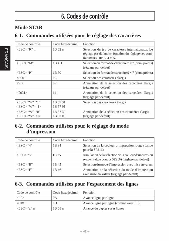
6-1. Commandes utilisées pour le réglage des caractères
Code de contrôle Code hexadécimal Fonction
<ESC> “R” n 1B 52 n Sélection du jeu de caractères internationaux. Leréglage par défaut est fonction du réglage des com-mutateurs DIP 3, 4 et 5.
<ESC> “M” 1B 4D Sélection du format de caractère 7 × 7 (demi points)(réglage par défaut)
<ESC> “P” 1B 50 Sélection du format de caractère 9 × 7 (demi points)
<SO> 0E Sélection des caractères élargis
<SI> 0F Annulation de la sélection des caractères élargis(réglage par défaut)
<DC4> 14 Annulation de la sélection des caractères élargis(réglage par défaut)
<ESC> “W” “1” 1B 57 31 Sélection des caractères élargis<ESC> “W” <1> 1B 57 01
<ESC> “W” “0” 1B 57 30 Annulation de la sélection des caractères élargis<ESC> “W” <0> 1B 57 00 (réglage par défaut)
6-2. Commandes utilisées pour le réglage du moded’impression
Code de contrôle Code hexadécimal Fonction
<ESC> “4” 1B 34 Sélection de la couleur d’impression rouge (validepour la SP216)
<ESC> “5” 1B 35 Annulation de la sélection de la couleur d’impressionrouge (valide pour la SP216) (réglage par défaut)
<ESC> “E” 1B 45 Sélection du mode d’impression avec mise en valeur
<ESC> “F” 1B 46 Annulation de la sélection du mode d’impressionavec mise en valeur (réglage par défaut)
6-3. Commandes utilisées pour l’espacement des lignes
Code de contrôle Code hexadécimal Fonction
<LF> 0A Avance ligne par ligne
<CR> 0D Avance ligne par ligne (comme avec LF)
<ESC> “a” n 1B 61 n Avance du papier sur n lignes
– 42 –
FR
AN
ÇA
IS
6-4. Commandes utilisées pour le pilotage des appareilspériphériques
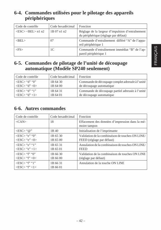
Code de contrôle Code hexadécimal Fonction
<ESC> <BEL> n1 n2 1B 07 n1 n2 Réglage de la largeur d’impulsion d’entraînementdu périphérique (réglage par défaut)
<BEL> 07 Commande d’entraînement différé “A” de l’appa-reil périphérique 1
<FS> 1C Commande d’entraînement immédiat “B” de l’ap-pareil périphérique 1
6-5. Commandes de pilotage de l’unité de découpageautomatique (Modèle SP240 seulement)
Code de contrôle Code hexadécimal Fonction
<ESC> “d” “0” 1B 64 30 Commande de découpage complet adressée à l’unité<ESC> “d” <0> 1B 64 00 de découpage automatique
<ESC> “d” “1” 1B 64 31 Commande de découpage partiel adressée à l’unité<ESC> “d” <1> 1B 64 01 de découpage automatique
6-6. Autres commandes
Code de contrôle Code hexadécimal Fonction
<CAN> 18 Effacement des données d’impression dans la mé-moire tampon
<ESC> “@” 1B 40 Initialisation de l’imprimante
<ESC> “e” “0” 1B 65 30 Validation de la combinaison de touches ON LINE/<ESC> “e” <0> 1B 65 00 FEED (réglage par défaut)
<ESC> “e” “1” 1B 65 31 Annulation de la combinaison de touches ON LINE/<ESC> “e” <1> 1B 65 01 FEED
<ESC> “f” “0” 1B 66 30 Validation de la combinaison de touches ON LINE<ESC> “f” <0> 1B 66 00 (réglage par défaut)
<ESC> “f” “1” 1B 66 31 Annulation de la touche ON LINE<ESC> “f” <1> 1B 66 01

– 43 –
FR
AN
ÇA
IS

– 44 –
DE
UT
SC
H
INHALTSVERZEICHNIS1. Kurzbeschreibung ............................................................................................452. Auspacken und Aufstellen ...............................................................................46
2-1. Überprüfen ...........................................................................................462-2. Wahl eines Aufstellungsorts für den Drucker ......................................472-3. Hinweise zum Umgang ........................................................................472-4. Wartung ...............................................................................................47
3. Beschreibung und Bezeichnung der Geräteteile ..............................................48
4. Einlegen von Farbbandkassette und Papier .....................................................504-1. Typ SP210............................................................................................504-2. Typ SP240............................................................................................534-3. Entfernen des Rollenpapiers ................................................................584-4. Anschließen des Schnittstellenkabels ..................................................58
5. Bedienfeld ........................................................................................................605-1. Grundlegender Betrieb .........................................................................605-2. Tastenbedienung (kombinierte Tastenbedienung) ...............................61
6. Steuercodes ......................................................................................................63STAR-Modus ...............................................................................................636-1. Steuercodes für Zeicheneinstellung .....................................................636-2. Steuercodes für Druckmoduseinstellung .............................................636-3. Steuercodes für Zeilenabstand .............................................................636-4. Steuercodes für Peripheriegeräte .........................................................646-5. Steuerung für Schneidwerk (nur Typ SP240) ......................................646-6. Andere Steuercodes .............................................................................64
ANHANG ............................................................................................................87
Der Anhand dieser Bedienungsanleitung ist nur in englischer Sprache.
– 45 –
DE
UT
SC
H
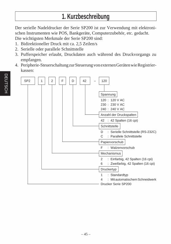
Der serielle Nadeldrucker der Serie SP200 ist zur Verwendung mit elektroni-schen Instrumenten wie POS, Bankgeräte, Computerzubehör, etc. gedacht.Die wichtigsten Merkmale der Serie SP200 sind:1. Bidirektioneller Druck mit ca. 2,5 Zeilen/s2. Serielle oder parallele Schnittstelle3. Pufferspeicher erlaubt, Druckdaten auch während des Druckvorgangs zu
empfangen.4. Peripherie-Steuerschaltung zur Steuerung von externen Geräten wie Registrier-
kassen:
SP2 1 2 F D 42 – 120
Spannung
120 : 120 V AC230 : 230 V AC240 : 240 V AC
Anzahl der Druckspalten
42 : 42 Spalten (16 cpi)
Schnittstelle
D : Serielle Schnittstelle (RS-232C)C : Parallele Schnittstelle
Papiervorschub
F : Walzenvorschub
Mechanismus
2 : Einfarbig, 42 Spalten (16 cpi)6 : Zweifarbig, 42 Spalten (16 cpi)
Druckertyp
1 : Standardtyp4 : Mit automatischem SchneidwerkDrucker Serie SP200
1. Kurzbeschreibung
– 46 –
DE
UT
SC
H
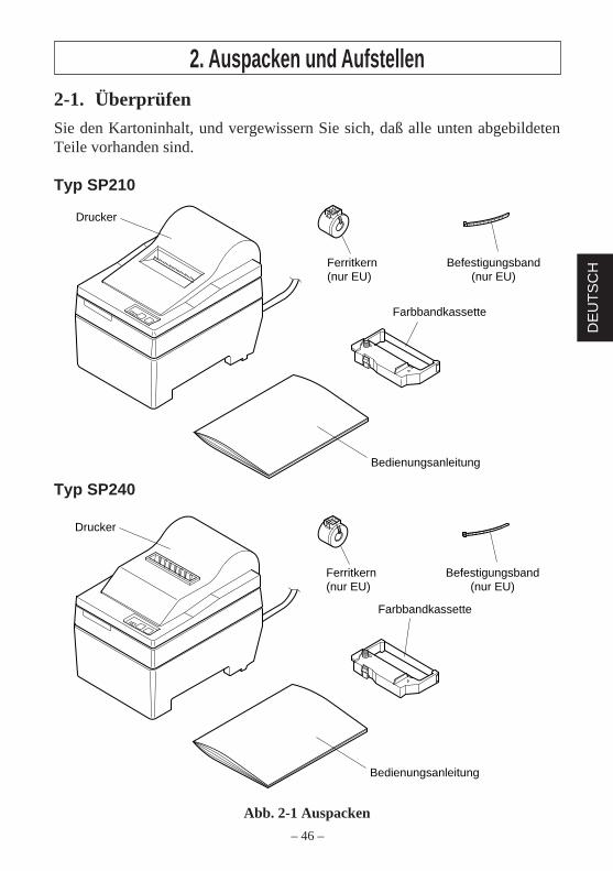
2. Auspacken und Aufstellen2-1. Überprüfen
Sie den Kartoninhalt, und vergewissern Sie sich, daß alle unten abgebildetenTeile vorhanden sind.
Typ SP210
Typ SP240
Abb. 2-1 Auspacken
Drucker
Bedienungsanleitung
Farbbandkassette
Ferritkern(nur EU)
Befestigungsband(nur EU)
Bedienungsanleitung
Farbbandkassette
Drucker
Ferritkern(nur EU)
Befestigungsband(nur EU)
– 47 –
DE
UT
SC
H
2-2. Wahl eines Aufstellungsorts für den DruckerBevor Sie den Drucker auspacken, sollten Sie einige Minuten damit verbringen,einen geeigneten Aufstellungsort auszusuchen. Denken Sie dabei an die folgendenPunkte:1. Den Drucker vor Hitzequellen wie direktem Sonnenlicht oder Heizkörpern
schützen und von Feuchtigkeit und Staub fernhalten.2. Den Drucker auf einem flachen, aber festen Untergrund aufstellen, wo keine
Vibrationen vorhanden sind.3. Sicherstellen, daß der Drucker an eine einwandfreie Stromzufuhr angeschlossen ist.
Er sollte nicht an Steckdosen angeschlossen werden, an denen bereits Geräte mitmöglichen Netzstörungen wie Kopierer, Kühlschränke u.a. angeschlossen sind.
4. Die Versorgungsspannung muß dem Spannungswert auf dem Typenschild an derUnterseite des Druckers entsprechen.
5. Die verwendete Steckdose soll in der Nähe und frei zugänglich sein.
2-3. Hinweise zum Umgang1. Achten Sie darauf, keine Papierclips oder anderen Fremdkörper in den Drucker
fallen zu lassen. Diese können Betriebsstörungen oder Schäden am Gerät hervor-rufen.
2. Versuchen Sie nicht zu drucken, wenn kein Papier oder keine Farbbandkassetteeingelegt ist, da sonst der Druckkopf beschädigt werden kann.
3. Öffnen Sie nicht die Frontabdeckung während des Druckens.4. Berühren Sie nicht den Druckkopf sofort nach dem Druckvorgang, da dieser sehr
heiß wird.5. Verwenden Sie nur Rollenpapier, das nicht am Rollenkern festgeklebt ist.6. Wenn die Papierende-Markierung erscheint, tauschen Sie die Papierrolle aus,
bevor sie ganz verbraucht ist.
2-4. WartungIhr Drucker ist ein robust gebautes Gerät, sollte aber trotzdem mit einem gewissenMaß an Vorsicht behandelt werden, um Fehlfunktionen zu vermeiden. Zum Beispiel:1. Stellen Sie den Drucker in einer “komfortablen” Betriebsumgebung auf. Als
Faustregel gilt: Wo Sie sich wohlfühlen, fühlt sich der Drucker ebenfalls wohl.2. Setzen Sie den Drucker keinen Erschütterungen oder starken Vibrationen aus.3. Vermeiden Sie sehr staubige Umgebungen. Staub ist der Erzfeind aller Präzisions-
geräte.4. Zum Reinigen des Gehäuses verwenden Sie einen nur leicht mit Wasser, sehr
milder wässriger Seifenlösung oder ein wenig Alkohol angefeuchteten Lappen.Lassen Sie auf keinen Fall Flüssigkeiten in das Innere des Druckers geraten.
5. Das Innere des Druckers kann mit einem kleinen Reiniger oder einem Luftspray(in Fachgeschäften erhältlich) gereinigt werden. Bei dieser Arbeit darauf achten,keine Kabelverbindungen oder elektronische Bauteile zu verbiegen oder zubeschädigen.
– 48 –
DE
UT
SC
H
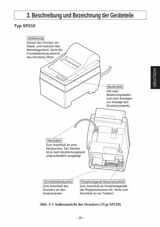
3. Beschreibung und Bezeichnung der GeräteteileTyp SP210
Abb. 3-1 Außenansicht des Druckers (Typ SP210)
Hat zwei Bedienungstasten und zwei Anzeigen zur Anzeige des Druckerzustands.
Bedienfeld
Schüzt den Drucker vor Staub, und reduziert das Betriebsgeräsch. Nicht die Frontabdeckung würend des Druckens öfnen.
Abdeckung
Zum Anschluß des Druckers an den Hostcomputer.
SchnittstellenbuchseZum Anschluß an Peripheriegeräte wie Registrierkassen etc. Nicht zum Anschluß an ein Telefon!
Peripheriegerät-Steueranschluß
Zum Anschluß an eine Netzbuchse. Der Stecker ist je nach Bestimmungsland unterschiedlich ausgelegt.
Netzkabel
– 49 –
DE
UT
SC
H
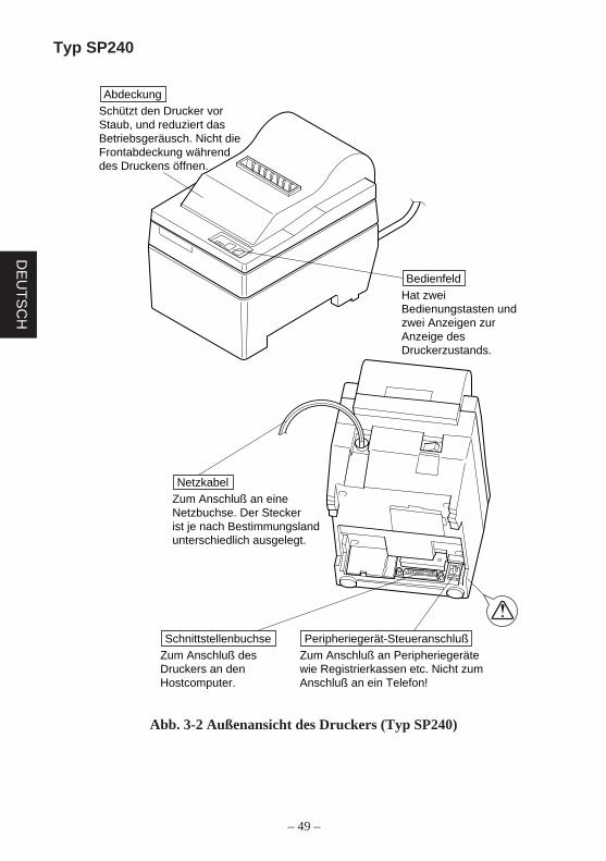
Typ SP240
Abb. 3-2 Außenansicht des Druckers (Typ SP240)
Hat zwei Bedienungstasten und zwei Anzeigen zur Anzeige des Druckerzustands.
Bedienfeld
Zum Anschluß des Druckers an den Hostcomputer.
SchnittstellenbuchseZum Anschluß an Peripheriegeräte wie Registrierkassen etc. Nicht zum Anschluß an ein Telefon!
Peripheriegerät-Steueranschluß
Schützt den Drucker vor Staub, und reduziert das Betriebsgeräusch. Nicht die Frontabdeckung während des Druckens öffnen.
Abdeckung
Zum Anschluß an eine Netzbuchse. Der Stecker ist je nach Bestimmungsland unterschiedlich ausgelegt.
Netzkabel
– 50 –
DE
UT
SC
H
Druckkopf
Farbband
Farbbandkassette
Farbbandzuführ-knopf
Kerbteil
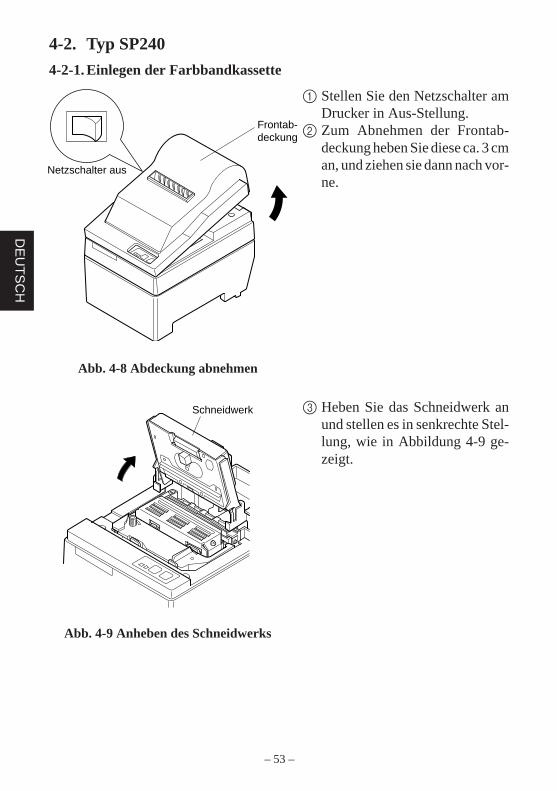
Frontab-deckung
Netzschalter aus
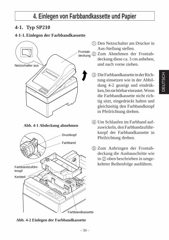
4. Einlegen von Farbbandkassette und Papier4-1. Typ SP210
4-1-1. Einlegen der Farbbandkassette
1 Den Netzschalter am Drucker inAus-Stellung stellen.
2 Zum Abnehmen der Frontab-deckung diese ca. 3 cm anheben,und nach vorne ziehen.
3 Die Farbbandkassette in der Rich-tung einsetzen wie in der Abbil-dung 4-2 gezeigt und eindrük-ken, bis sie hörbar einrastet. Wenndie Farbbandkassette nicht rich-tig sitzt, eingedrückt halten undgleichzeitig den Farbbandknopfin Pfeilrichtung drehen.
4 Um Schlaufen im Farbband auf-zuwickeln, den Farbbandzuführ-knopf der Farbbandkassette inPfeilrichtung drehen.
5 Zum Anbringen der Frontab-deckung die Ausbauschritte wiein 2 oben beschrieben in umge-kehrter Reihenfolge ausführen.
Abb. 4-1 Abdeckung abnehmen
Abb. 4-2 Einlegen der Farbbandkassette
– 51 –
DE
UT
SC
H
Abdeckung
FEED-Taste
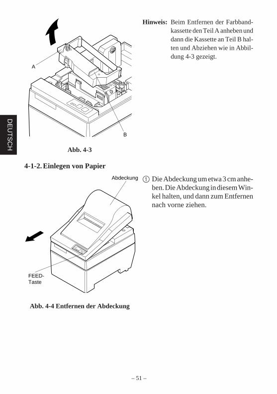
Hinweis: Beim Entfernen der Farbband-kassette den Teil A anheben unddann die Kassette an Teil B hal-ten und Abziehen wie in Abbil-dung 4-3 gezeigt.
A
B
Abb. 4-3
4-1-2. Einlegen von Papier
1 Die Abdeckung um etwa 3 cm anhe-ben. Die Abdeckung in diesem Win-kel halten, und dann zum Entfernennach vorne ziehen.
Abb. 4-4 Entfernen der Abdeckung
– 52 –
DE
UT
SC
H
Positionierungsrippe Abdeckung
Rollenpapier
Papierrollenhalter
Rollenpapier
Kern
Achse
Papierrollenhalter
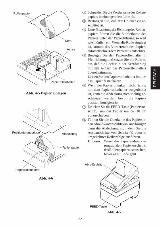
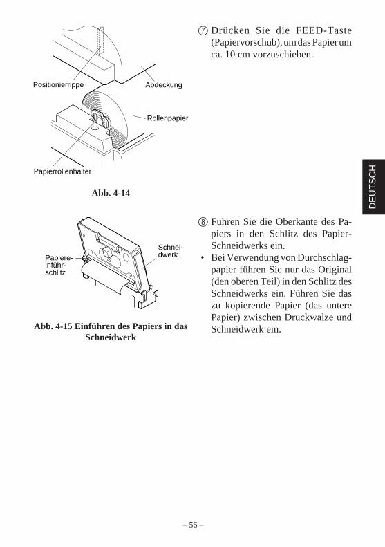
2 Schneiden Sie die Vorderkante des Rollen-papiers in einer geraden Linie ab.
3 Bestätigen Sie, daß der Drucker einge-schaltet ist.
4 Unter Beachtung der Richtung des Rollen-papiers führen Sie die Vorderkante desPapiers unter der Papierführung so weitwie möglich ein. Wenn die Rolle einglegtist, kommt das Vorderende des Papiersautomatisch aus dem Papierauslaufschlitz.
5 Bewegen Sie den Papierrollenhalter inPfeilrichtung und setzen Sie die Role soein, daß die Löcher in der Kernführungmit den Achsen des Papierrollenhaltersübereinstimmen.Lassen Sie den Papierrollenhalter los, umdas Papier festzuhalten.
6 Wenn der Papierrollenkern nicht richtigmit dem Papierrollenhalter ausgerichtetist, kann die Abdeckung nicht richtig ge-schlossen werden, bevor die Papier-position korrigiert ist.
7 Drücken Sie die FEED-Taste (Papiervor-schub), um das Papier um ca. 10 cmvorzuschieben.
8 Führen Sie die Oberkante des Papiers inden Abreißkantenschlitz ein, und bringendann die Abdeckung an, indem Sie dieAusbauschritte von Schritt 1 oben inumgekehrter Reihenfolge ausführen.Hinweis: Wenn die Papierendmarkie-
rung auf dem Papier erscheint,das Rollenpapier austauschen,bevor es zu Ende geht.
Abb. 4-7
Abb. 4-5 Papier einlegen
Abb. 4-6
FEED-Taste
Abreißschlitz
– 53 –
DE
UT
SC
H
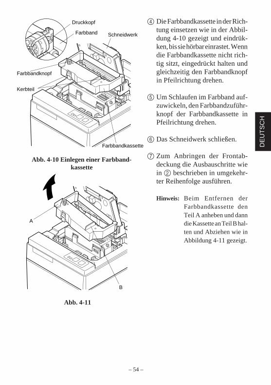
Schneidwerk
Frontab-deckung
Netzschalter aus
4-2. Typ SP240
4-2-1. Einlegen der Farbbandkassette
1 Stellen Sie den Netzschalter amDrucker in Aus-Stellung.
2 Zum Abnehmen der Frontab-deckung heben Sie diese ca. 3 cman, und ziehen sie dann nach vor-ne.
3 Heben Sie das Schneidwerk anund stellen es in senkrechte Stel-lung, wie in Abbildung 4-9 ge-zeigt.
Abb. 4-8 Abdeckung abnehmen
Abb. 4-9 Anheben des Schneidwerks
– 54 –
DE
UT
SC
H
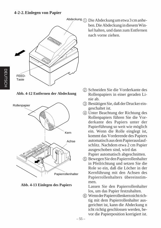
Druckkopf
Farbband Schneidwerk
Farbbandkassette
Farbbandknopf
Kerbteil
A
B
4 Die Farbbandkassette in der Rich-tung einsetzen wie in der Abbil-dung 4-10 gezeigt und eindrük-ken, bis sie hörbar einrastet. Wenndie Farbbandkassette nicht rich-tig sitzt, eingedrückt halten undgleichzeitig den Farbbandknopfin Pfeilrichtung drehen.
5 Um Schlaufen im Farbband auf-zuwickeln, den Farbbandzuführ-knopf der Farbbandkassette inPfeilrichtung drehen.
6 Das Schneidwerk schließen.
7 Zum Anbringen der Frontab-deckung die Ausbauschritte wiein 2 beschrieben in umgekehr-ter Reihenfolge ausführen.
Hinweis: Beim Entfernen derFarbbandkassette denTeil A anheben und danndie Kassette an Teil B hal-ten und Abziehen wie inAbbildung 4-11 gezeigt.
Abb. 4-10 Einlegen einer Farbband-kassette
Abb. 4-11
– 55 –
DE
UT
SC
H
Rollenpapier
Kern
Achse
Papierrollenhalter
Abdeckung
FEED-Taste
4-2-2. Einlegen von Papier
1 Die Abdeckung um etwa 3 cm anhe-ben. Die Abdeckung in diesem Win-kel halten, und dann zum Entfernennach vorne ziehen.
2 Schneiden Sie die Vorderkante desRollenpapiers in einer geraden Li-nie ab.
3 Bestätigen Sie, daß der Drucker ein-geschaltet ist.
4 Unter Beachtung der Richtung desRollenpapiers führen Sie die Vor-derkante des Papiers unter derPapierführung so weit wie möglichein. Wenn die Rolle einglegt ist,kommt das Vorderende des Papiersautomatisch aus dem Papierauslauf-schlitz. Nachdem etwa 2 cm Papierausgeschoben sind, wird dasPapier automatisch abgeschnitten.
5 Bewegen Sie den Papierrollenhalterin Pfeilrichtung und setzen Sie dieRole so ein, daß die Löcher in derKernführung mit den Achsen desPapierrollenhalters übereinstim-men.Lassen Sie den Papierrollenhalterlos, um das Papier festzuhalten.
6 Wenn der Papierrollenkern nicht rich-tig mit dem Papierrollenhalter aus-gerichtet ist, kann die Abdeckung nicht richtig geschlossen werden, be-vor die Papierposition korrigiert ist.
Abb. 4-12 Entfernen der Abdeckung
Abb. 4-13 Einlegen des Papiers
– 56 –
DE
UT
SC
H
Papiere-inführ-schlitz
Schnei-dwerk
Positionierrippe Abdeckung
Rollenpapier
Papierrollenhalter
7 Drücken Sie die FEED-Taste(Papiervorschub), um das Papier umca. 10 cm vorzuschieben.
8 Führen Sie die Oberkante des Pa-piers in den Schlitz des Papier-Schneidwerks ein.
• Bei Verwendung von Durchschlag-papier führen Sie nur das Original(den oberen Teil) in den Schlitz desSchneidwerks ein. Führen Sie daszu kopierende Papier (das unterePapier) zwischen Druckwalze undSchneidwerk ein.
Abb. 4-14
Abb. 4-15 Einführen des Papiers in dasSchneidwerk
– 57 –
DE
UT
SC
H Papier-auslaß
Schneidwerk
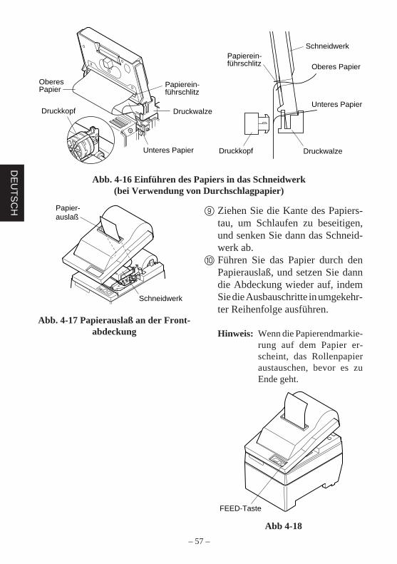
Abb. 4-16 Einführen des Papiers in das Schneidwerk(bei Verwendung von Durchschlagpapier)
9 Ziehen Sie die Kante des Papiers-tau, um Schlaufen zu beseitigen,und senken Sie dann das Schneid-werk ab.
0 Führen Sie das Papier durch denPapierauslaß, und setzen Sie danndie Abdeckung wieder auf, indemSie die Ausbauschritte in umgekehr-ter Reihenfolge ausführen.
Hinweis: Wenn die Papierendmarkie-rung auf dem Papier er-scheint, das Rollenpapieraustauschen, bevor es zuEnde geht.
Abb 4-18
Abb. 4-17 Papierauslaß an der Front-abdeckung
FEED-Taste
Papierein-führschlitz
Druckwalze
Unteres Papier
Oberes Papier
Druckkopf
Druckkopf
Papierein-führschlitz
Schneidwerk
Druckwalze
Unteres Papier
Oberes Papier
– 58 –
DE
UT
SC
H
Ferritkern
Schnittstelle kabel
Maximum 5 cm
Befesti-gungsband
Ziehen und abschneiden
4-3. Entfernen des Rollenpapiers
Nehmen Sie die Abdeckung ab, und schneiden Sie das Papier in der Nähe derPapierführung ab. Dann drücken Sie die FEED-Taste, um den Rest des Papiersauszugeben, der noch in der Einheit ist.Wenn das Papier verbraucht ist, blinkt das Lämpchen POWER.
Hinweis 1. Durch Drücken der FEED-Taste wird der Rest des noch im Druckerbefindlichen Papiers ausgegeben.
2. Wenn die Papier-Verbraucht-Markierung auf dem Papier erscheint,tauschen Sie die Rolle aus, bevor das Papier ganz zu Ende ist.
3. Beim Entfernen des Kerns der Papierrolle den Rollenpapierhalter öff-nen.
4-4. Anschließen des Schnittstellenkabels
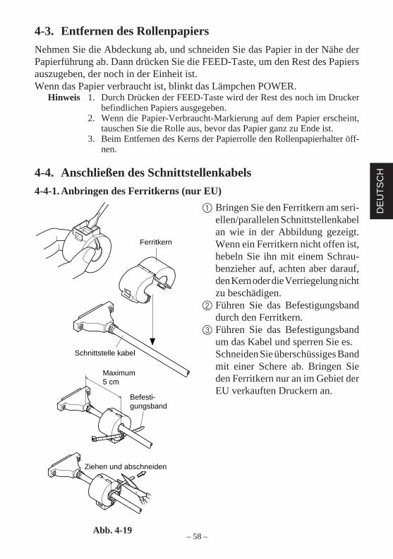
4-4-1. Anbringen des Ferritkerns (nur EU)
1 Bringen Sie den Ferritkern am seri-ellen/parallelen Schnittstellenkabelan wie in der Abbildung gezeigt.Wenn ein Ferritkern nicht offen ist,hebeln Sie ihn mit einem Schrau-benzieher auf, achten aber darauf,den Kern oder die Verriegelung nichtzu beschädigen.
2 Führen Sie das Befestigungsbanddurch den Ferritkern.
3 Führen Sie das Befestigungsbandum das Kabel und sperren Sie es.Schneiden Sie überschüssiges Bandmit einer Schere ab. Bringen Sieden Ferritkern nur an im Gebiet derEU verkauften Druckern an.
Abb. 4-19
– 59 –
DE
UT
SC
H
Ferritkern (nur EU)
Ferritkern (nur EU)
Schraubenzieher
Schrauben
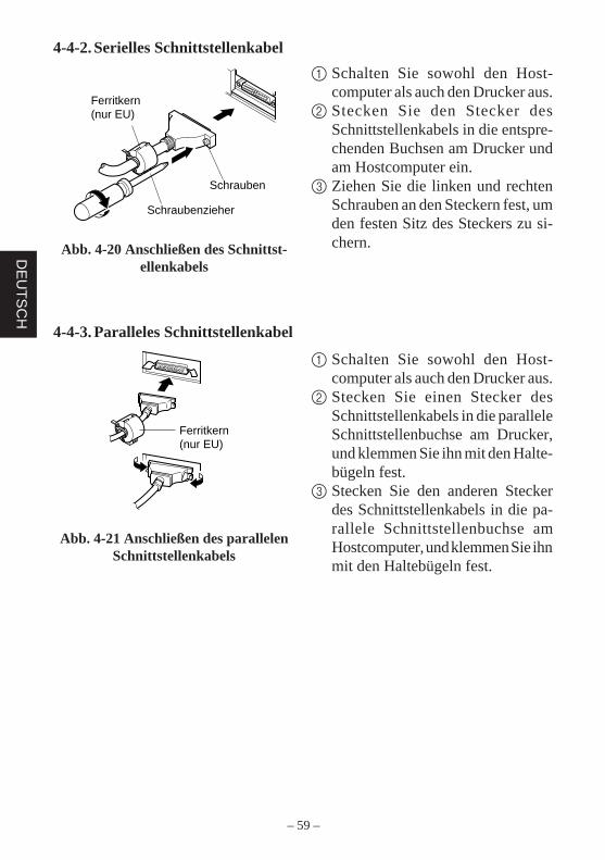
4-4-2. Serielles Schnittstellenkabel
1 Schalten Sie sowohl den Host-computer als auch den Drucker aus.
2 Stecken Sie den Stecker desSchnittstellenkabels in die entspre-chenden Buchsen am Drucker undam Hostcomputer ein.
3 Ziehen Sie die linken und rechtenSchrauben an den Steckern fest, umden festen Sitz des Steckers zu si-chern.Abb. 4-20 Anschließen des Schnittst-
ellenkabels
4-4-3. Paralleles Schnittstellenkabel
1 Schalten Sie sowohl den Host-computer als auch den Drucker aus.
2 Stecken Sie einen Stecker desSchnittstellenkabels in die paralleleSchnittstellenbuchse am Drucker,und klemmen Sie ihn mit den Halte-bügeln fest.
3 Stecken Sie den anderen Steckerdes Schnittstellenkabels in die pa-rallele Schnittstellenbuchse amHostcomputer, und klemmen Sie ihnmit den Haltebügeln fest.
Abb. 4-21 Anschließen des parallelenSchnittstellenkabels
– 60 –
DE
UT
SC
H
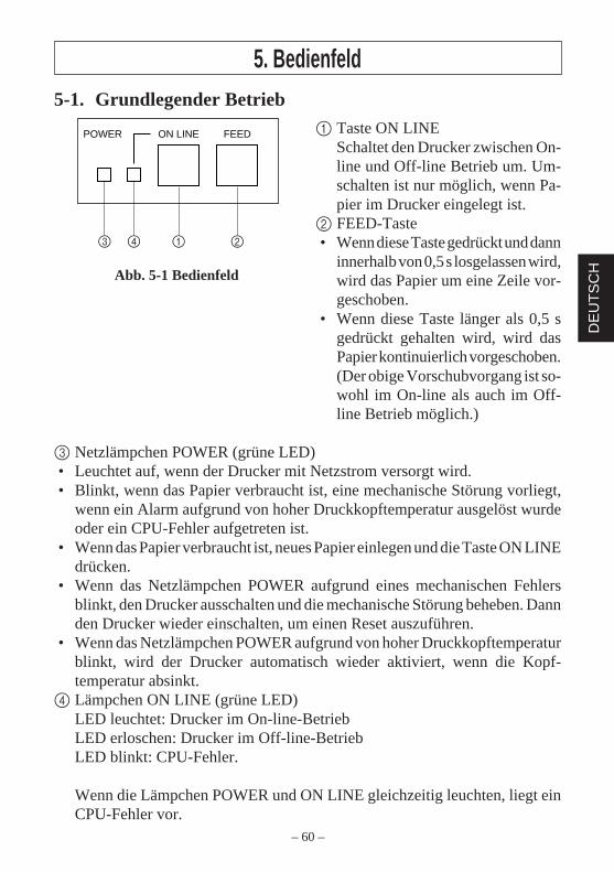
5. Bedienfeld5-1. Grundlegender Betrieb
1 Taste ON LINESchaltet den Drucker zwischen On-line und Off-line Betrieb um. Um-schalten ist nur möglich, wenn Pa-pier im Drucker eingelegt ist.
2 FEED-Taste• Wenn diese Taste gedrückt und dann
innerhalb von 0,5 s losgelassen wird,wird das Papier um eine Zeile vor-geschoben.
• Wenn diese Taste länger als 0,5 sgedrückt gehalten wird, wird dasPapier kontinuierlich vorgeschoben.(Der obige Vorschubvorgang ist so-wohl im On-line als auch im Off-line Betrieb möglich.)
3 Netzlämpchen POWER (grüne LED)• Leuchtet auf, wenn der Drucker mit Netzstrom versorgt wird.• Blinkt, wenn das Papier verbraucht ist, eine mechanische Störung vorliegt,
wenn ein Alarm aufgrund von hoher Druckkopftemperatur ausgelöst wurdeoder ein CPU-Fehler aufgetreten ist.
• Wenn das Papier verbraucht ist, neues Papier einlegen und die Taste ON LINEdrücken.
• Wenn das Netzlämpchen POWER aufgrund eines mechanischen Fehlersblinkt, den Drucker ausschalten und die mechanische Störung beheben. Dannden Drucker wieder einschalten, um einen Reset auszuführen.
• Wenn das Netzlämpchen POWER aufgrund von hoher Druckkopftemperaturblinkt, wird der Drucker automatisch wieder aktiviert, wenn die Kopf-temperatur absinkt.
4 Lämpchen ON LINE (grüne LED)LED leuchtet: Drucker im On-line-BetriebLED erloschen: Drucker im Off-line-BetriebLED blinkt: CPU-Fehler.
Wenn die Lämpchen POWER und ON LINE gleichzeitig leuchten, liegt einCPU-Fehler vor.
ON LINEPOWER FEED
3 4 1 2
Abb. 5-1 Bedienfeld
– 61 –
DE
UT
SC
H
5-2. Tastenbedienung (kombinierte Tastenbedienung)
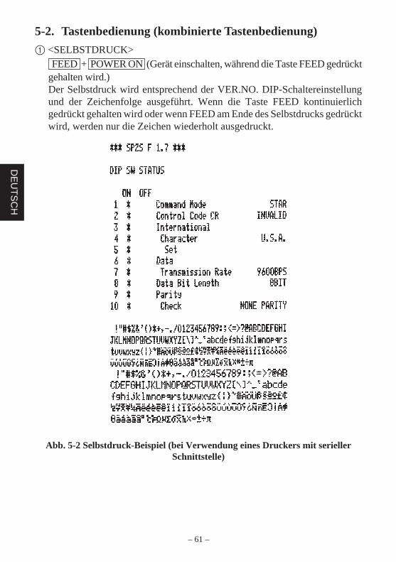
1 <SELBSTDRUCK> FEED + POWER ON (Gerät einschalten, während die Taste FEED gedrücktgehalten wird.)Der Selbstdruck wird entsprechend der VER.NO. DIP-Schaltereinstellungund der Zeichenfolge ausgeführt. Wenn die Taste FEED kontinuierlichgedrückt gehalten wird oder wenn FEED am Ende des Selbstdrucks gedrücktwird, werden nur die Zeichen wiederholt ausgedruckt.
Abb. 5-2 Selbstdruck-Beispiel (bei Verwendung eines Druckers mit seriellerSchnittstelle)
– 62 –
DE
UT
SC
H
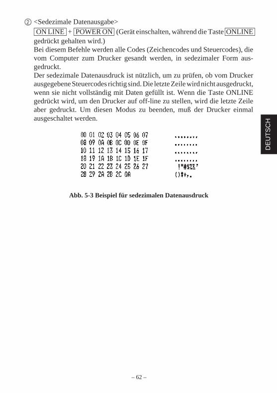
2 <Sedezimale Datenausgabe> ON LINE + POWER ON (Gerät einschalten, während die Taste ONLINEgedrückt gehalten wird.)Bei diesem Befehle werden alle Codes (Zeichencodes und Steuercodes), dievom Computer zum Drucker gesandt werden, in sedezimaler Form aus-gedruckt.Der sedezimale Datenausdruck ist nützlich, um zu prüfen, ob vom Druckerausgegebene Steuercodes richtig sind. Die letzte Zeile wird nicht ausgedruckt,wenn sie nicht vollständig mit Daten gefüllt ist. Wenn die Taste ONLINEgedrückt wird, um den Drucker auf off-line zu stellen, wird die letzte Zeileaber gedruckt. Um diesen Modus zu beenden, muß der Drucker einmalausgeschaltet werden.
Abb. 5-3 Beispiel für sedezimalen Datenausdruck
– 63 –
DE
UT
SC
H
6. SteuercodesSTAR-Modus
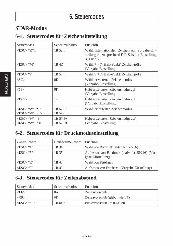
6-1. Steuercodes für Zeicheneinstellung
Steuercodes Sedezimalcodes Funktion
<ESC> “R” n 1B 52 n Wählt internationalen Zeichensatz. Vorgabe-Ein-stellung ist entsprechend DIP-Schalter-Einstellung3, 4 und 5.
<ESC> “M” 1B 4D Wählt 7 × 7 (Halb-Punkt) Zeichengröße(Vorgabe-Einstellung)
<ESC> “P” 1B 50 Wählt 9 × 7 (Halb-Punkt) Zeichengröße
<SO> 0E Wählt erweiterten Zeichenmodus(Vorgabe-Einstellung)
<SI> 0F Hebt erweiterten Zeichenmodus auf(Vorgabe-Einstellung)
<DC4> 14 Hebt erweiterten Zeichenmodus auf(Vorgabe-Einstellung)
<ESC> “W” “1” 1B 57 31 Wählt erweiterten Zeichenmodus<ESC> “W” <1> 1B 57 01
<ESC> “W” “0” 1B 57 30 Hebt erweiterten Zeichenmodus auf<ESC> “W” <0> 1B 57 00 (Vorgabe-Einstellung)
6-2. Steuercodes für Druckmoduseinstellung
Control codes Hexadecimal codes Function
<ESC> “4” 1B 34 Wahl von Rotdruck (aktiv für SP216)
<ESC> “5” 1B 35 Aufheben von Rotdruck (aktiv für SP216) (Vor-gabe-Einstellung)
<ESC> “E” 1B 45 Wahl von Fettdruck
<ESC> “F” 1B 46 Aufheben von Fettdruck (Vorgabe-Einstellung)
6-3. Steuercodes für Zeilenabstand
Steuercodes Sedezimalcodes Funktion
<LF> 0A Zeilenvorschub
<CR> 0D Zeilenvorschub (gleich wie LF)
<ESC> “a” n 1B 61 n Papiervorschub um n Zeilen
– 64 –
DE
UT
SC
H
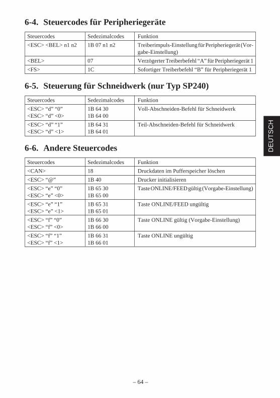
6-4. Steuercodes für Peripheriegeräte
Steuercodes Sedezimalcodes Funktion
<ESC> <BEL> n1 n2 1B 07 n1 n2 Treiberimpuls-Einstellung für Peripheriegerät (Vor-gabe-Einstellung)
<BEL> 07 Verzögerter Treiberbefehl “A” für Peripheriegerät 1
<FS> 1C Sofortiger Treiberbefehl “B” für Peripheriegerät 1
6-5. Steuerung für Schneidwerk (nur Typ SP240)
Steuercodes Sedezimalcodes Funktion
<ESC> “d” “0” 1B 64 30 Voll-Abschneiden-Befehl für Schneidwerk<ESC> “d” <0> 1B 64 00
<ESC> “d” “1” 1B 64 31 Teil-Abschneiden-Befehl für Schneidwerk<ESC> “d” <1> 1B 64 01
6-6. Andere Steuercodes
Steuercodes Sedezimalcodes Funktion
<CAN> 18 Druckdaten im Pufferspeicher löschen
<ESC> “@” 1B 40 Drucker initialisieren
<ESC> “e” “0” 1B 65 30 Taste ONLINE/FEED gültig (Vorgabe-Einstellung)<ESC> “e” <0> 1B 65 00
<ESC> “e” “1” 1B 65 31 Taste ONLINE/FEED ungültig<ESC> “e” <1> 1B 65 01
<ESC> “f” “0” 1B 66 30 Taste ONLINE gültig (Vorgabe-Einstellung)<ESC> “f” <0> 1B 66 00
<ESC> “f” “1” 1B 66 31 Taste ONLINE ungültig<ESC> “f” <1> 1B 66 01

– 65 –
DE
UT
SC
H
– 66 –
ITA
LIA
NO
INDICE1. Descrizione ......................................................................................................672. Disimballaggio e installazione ........................................................................68
2-1. Disimballaggio .....................................................................................682-2. Collocazione della stampante ..............................................................692-3. Precauzioni per l’uso............................................................................692-4. Manutenzione .......................................................................................69
3. Identificazione delle parti e nomenclatura ......................................................70
4. Inserimento della cartuccia nastro e della carta ...............................................724-1. Tipo SP210 ..........................................................................................724-2. Tipo SP240 ..........................................................................................754-3. Rimozione della carta ..........................................................................804-4. Collegamento del cavo interfaccia .......................................................80
5. Pannello comandi ............................................................................................825-1. Funzionamento basilare .......................................................................825-2. Operazioni con gli interruttori
(operazioni combinate degli interruttori) .............................................836. Codici di controllo ...........................................................................................85
Modo STAR .................................................................................................856-1. Codici di controllo usati nell’impostazione dei caratteri .....................856-2. Codici di controllo usati nell’impostazione del modo di stampa.........856-3. Codici di controllo usati nella spaziatura delle righe ...........................856-4. Codici di controllo usati per unità periferiche .....................................866-5. Controllo della taglierina automatica (solo tipo SP240) ......................866-6. Altri codici di controllo ........................................................................86
APPENDICE .......................................................................................................87
L’Appendice appare solo nella sezione in inglese di questo manuale.
– 67 –
ITA
LIAN
O
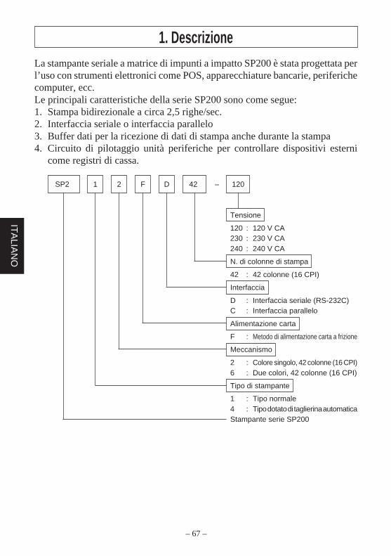
La stampante seriale a matrice di impunti a impatto SP200 è stata progettata perl’uso con strumenti elettronici come POS, apparecchiature bancarie, periferichecomputer, ecc.Le principali caratteristiche della serie SP200 sono come segue:1. Stampa bidirezionale a circa 2,5 righe/sec.2. Interfaccia seriale o interfaccia parallelo3. Buffer dati per la ricezione di dati di stampa anche durante la stampa4. Circuito di pilotaggio unità periferiche per controllare dispositivi esterni
come registri di cassa.
SP2 1 2 F D 42 – 120
Tensione
120 : 120 V CA230 : 230 V CA240 : 240 V CA
N. di colonne di stampa
42 : 42 colonne (16 CPI)
Interfaccia
D : Interfaccia seriale (RS-232C)C : Interfaccia parallelo
Alimentazione carta
F : Metodo di alimentazione carta a frizione
Meccanismo
2 : Colore singolo, 42 colonne (16 CPI)6 : Due colori, 42 colonne (16 CPI)
Tipo di stampante
1 : Tipo normale4 : Tipo dotato di taglierina automaticaStampante serie SP200
1. Descrizione
– 68 –
ITA
LIA
NO
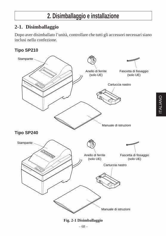
2. Disimballaggio e installazione2-1. Disimballaggio
Dopo aver disimballato l’unità, controllare che tutti gli accessori necessari sianoinclusi nella confezione.
Tipo SP210
Tipo SP240
Fig. 2-1 Disimballaggio
Stampante
Manuale di istruzioni
Cartuccia nastro
Anello di ferrite(solo UE)
Fascetta di fissaggio(solo UE)
Manuale di istruzioni
Cartuccia nastro
Stampante
Anello di ferrite(solo UE)
Fascetta di fissaggio(solo UE)
– 69 –
ITA
LIAN
O
2-2. Collocazione della stampanteQuando si colloca la stampante, tenere presenti le seguenti considerazioni:1. Proteggere la stampante da calore eccessivo come luce solare diretta o
caloriferi e tenerla lontana da umidità e polvere.2. Collocare la stampante su una superficie stabile e piana che non sia soggetta
a vibrazioni.3. Collegare alla stampante una fonte di alimentazione stabile che non sia
soggetta a picchi.Per esempio non collegarla sullo stesso circuito di apparecchiature grandi cheproducono disturbi, come frigoriferi o condizionatori d’aria.
4. Assicurarsi che la tensione della linea corrisponda alla tensione specificatasulla piastrina di identificazione della stampante.
5. Per scollegare la stampante, scollegare la spina dalla presa di corrente, che sideve trovare vicino alla stampante e in un luogo facilmente accessibile.
2-3. Precauzioni per l’uso1. Fare attenzione a non lasciar cadere graffette, spilli e altri oggetti estranei
nell’unità perché potrebbero causare problemi di funzionamento.2. Non tentare di stampare quando la carta o la cartuccia nastro non sono inserite
nella stampante, altrimenti la testina di stampa potrebbe essere danneggiata.3. Non aprire il coperchio durante la stampa.4. Non toccare la testina di stampa immediatamente dopo la stampa perché
scotta.5. Usare solo carta in rotoli che non è incollata all’anima di cartone.6. Quando il segno di fine carta appare sulla carta, sostituire il rotolo di carta
prima che finisca.
2-4. ManutenzioneLa stampante è fondamentalmente robusta, ma deve essere trattata con una certacura per evitare problemi di funzionamento. Per esempio:1. Tenere la stampante in un ambiente “confortevole”. In parole povere, se
l’ambiente è confortevole per le persone sarà adatto anche per la stampante.2. Non esporre la stampante a urti o vibrazioni eccessive.3. Evitare ambienti troppo polverosi. La polvere è il nemico di tutte le
apparecchiature meccaniche di precisione.4. Per pulire l’esterno della stampante usare un panno appena inumidito con
acqua e un poco di detergente o di alcool, ma evitare la penetrazione di liquidonella stampante.
5. L’interno della stampante può essere pulito con un piccolo pulitore o unabombola di aria compressa (venduta a questo scopo). Quando si esegue questaoperazione, assicurarsi di non piegare o danneggiare i collegamenti dei cavio i componenti elettronici.
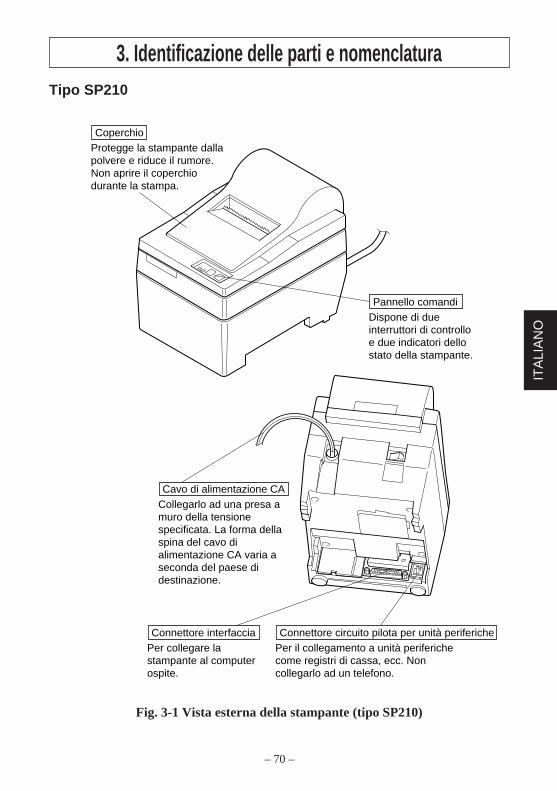
– 70 –
ITA
LIA
NO
3. Identificazione delle parti e nomenclaturaTipo SP210
Fig. 3-1 Vista esterna della stampante (tipo SP210)
Dispone di due interruttori di controllo e due indicatori dello stato della stampante.
Pannello comandi
Protegge la stampante dalla polvere e riduce il rumore. Non aprire il coperchio durante la stampa.
Coperchio
Per collegare la stampante al computer ospite.
Connettore interfacciaPer il collegamento a unità periferiche come registri di cassa, ecc. Non collegarlo ad un telefono.
Connettore circuito pilota per unità periferiche
Collegarlo ad una presa a muro della tensione specificata. La forma della spina del cavo di alimentazione CA varia a seconda del paese di destinazione.
Cavo di alimentazione CA
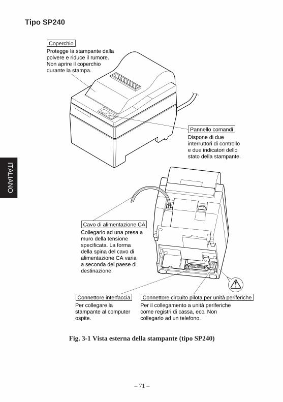
– 71 –
ITA
LIAN
O
Tipo SP240
Fig. 3-1 Vista esterna della stampante (tipo SP240)
Dispone di due interruttori di controllo e due indicatori dello stato della stampante.
Pannello comandi
Per collegare la stampante al computer ospite.
Connettore interfacciaPer il collegamento a unità periferiche come registri di cassa, ecc. Non collegarlo ad un telefono.
Connettore circuito pilota per unità periferiche
Protegge la stampante dalla polvere e riduce il rumore. Non aprire il coperchio durante la stampa.
Coperchio
Collegarlo ad una presa a muro della tensione specificata. La forma della spina del cavo di alimentazione CA varia a seconda del paese di destinazione.
Cavo di alimentazione CA
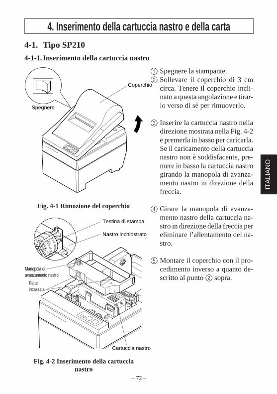
– 72 –
ITA
LIA
NO
Testina di stampa
Nastro inchiostrato
Cartuccia nastro
Manopola di avanzamento nastro
Parte incassata
Coperchio
Spegnere
4. Inserimento della cartuccia nastro e della carta4-1. Tipo SP210
4-1-1. Inserimento della cartuccia nastro
1 Spegnere la stampante.2 Sollevare il coperchio di 3 cm
circa. Tenere il coperchio incli-nato a questa angolazione e tirar-lo verso di sè per rimuoverlo.
3 Inserire la cartuccia nastro nelladirezione mostrata nella Fig. 4-2e premerla in basso per caricarla.Se il caricamento della cartuccianastro non è soddisfacente, pre-mere in basso la cartuccia nastrogirando la manopola di avanza-mento nastro in direzione dellafreccia.
4 Girare la manopola di avanza-mento nastro della cartuccia na-stro in direzione della freccia pereliminare l’allentamento del na-stro.
5 Montare il coperchio con il pro-cedimento inverso a quanto de-scritto al punto 2 sopra.
Fig. 4-1 Rimozione del coperchio
Fig. 4-2 Inserimento della cartuccianastro
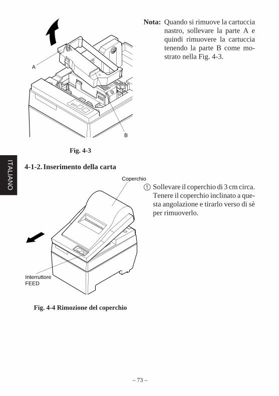
– 73 –
ITA
LIAN
O
Coperchio
Interruttore FEED
Nota: Quando si rimuove la cartuccianastro, sollevare la parte A equindi rimuovere la cartucciatenendo la parte B come mo-strato nella Fig. 4-3.
A
B
Fig. 4-3
4-1-2. Inserimento della carta
Fig. 4-4 Rimozione del coperchio
1 Sollevare il coperchio di 3 cm circa.Tenere il coperchio inclinato a que-sta angolazione e tirarlo verso di sèper rimuoverlo.
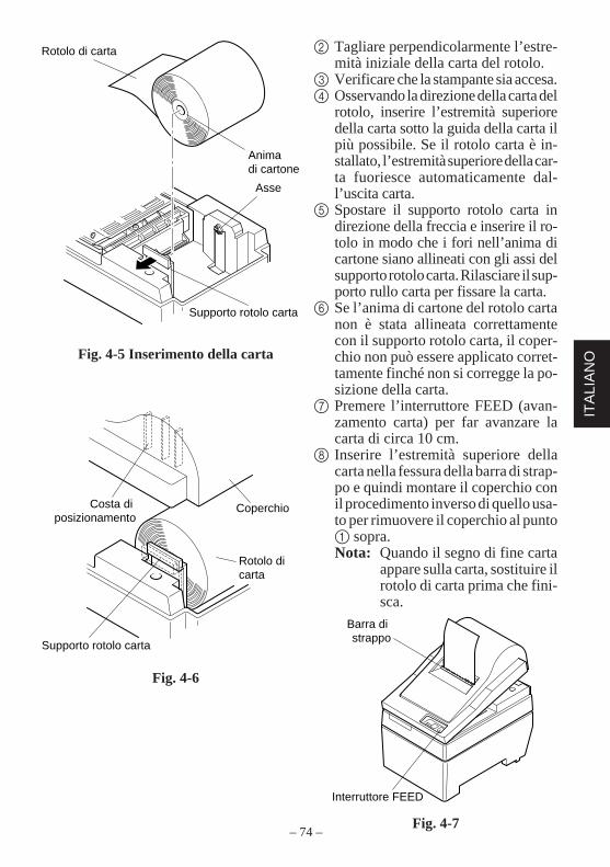
– 74 –
ITA
LIA
NO
Costa di posizionamento
Coperchio
Rotolo di carta
Supporto rotolo carta
Rotolo di carta
Anima di cartone
Asse
Supporto rotolo carta
2 Tagliare perpendicolarmente l’estre-mità iniziale della carta del rotolo.
3 Verificare che la stampante sia accesa.4 Osservando la direzione della carta del
rotolo, inserire l’estremità superioredella carta sotto la guida della carta ilpiù possibile. Se il rotolo carta è in-stallato, l’estremità superiore della car-ta fuoriesce automaticamente dal-l’uscita carta.
5 Spostare il supporto rotolo carta indirezione della freccia e inserire il ro-tolo in modo che i fori nell’anima dicartone siano allineati con gli assi delsupporto rotolo carta. Rilasciare il sup-porto rullo carta per fissare la carta.
6 Se l’anima di cartone del rotolo cartanon è stata allineata correttamentecon il supporto rotolo carta, il coper-chio non può essere applicato corret-tamente finché non si corregge la po-sizione della carta.
7 Premere l’interruttore FEED (avan-zamento carta) per far avanzare lacarta di circa 10 cm.
8 Inserire l’estremità superiore dellacarta nella fessura della barra di strap-po e quindi montare il coperchio conil procedimento inverso di quello usa-to per rimuovere il coperchio al punto1 sopra.Nota: Quando il segno di fine carta
appare sulla carta, sostituire ilrotolo di carta prima che fini-sca.
Fig. 4-7
Fig. 4-5 Inserimento della carta
Fig. 4-6
Interruttore FEED
Barra di strappo
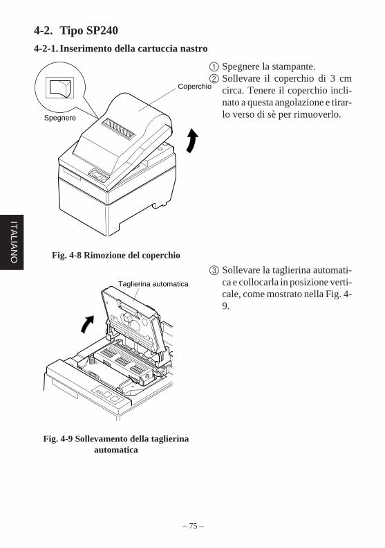
– 75 –
ITA
LIAN
O
Taglierina automatica
Coperchio
Spegnere
4-2. Tipo SP240
4-2-1. Inserimento della cartuccia nastro
1 Spegnere la stampante.2 Sollevare il coperchio di 3 cm
circa. Tenere il coperchio incli-nato a questa angolazione e tirar-lo verso di sè per rimuoverlo.
3 Sollevare la taglierina automati-ca e collocarla in posizione verti-cale, come mostrato nella Fig. 4-9.
Fig. 4-8 Rimozione del coperchio
Fig. 4-9 Sollevamento della taglierinaautomatica
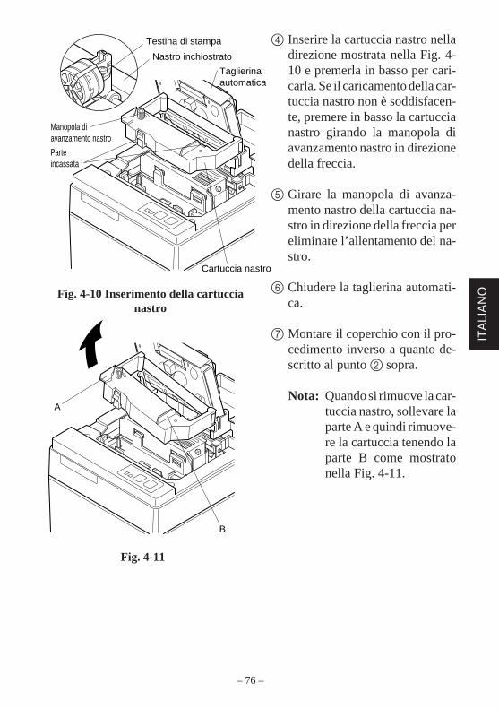
– 76 –
ITA
LIA
NO
A
B
Testina di stampa
Nastro inchiostrato
Taglierina automatica
Cartuccia nastro
Manopola di avanzamento nastro
Parte incassata
4 Inserire la cartuccia nastro nelladirezione mostrata nella Fig. 4-10 e premerla in basso per cari-carla. Se il caricamento della car-tuccia nastro non è soddisfacen-te, premere in basso la cartuccianastro girando la manopola diavanzamento nastro in direzionedella freccia.
5 Girare la manopola di avanza-mento nastro della cartuccia na-stro in direzione della freccia pereliminare l’allentamento del na-stro.
6 Chiudere la taglierina automati-ca.
7 Montare il coperchio con il pro-cedimento inverso a quanto de-scritto al punto 2 sopra.
Nota: Quando si rimuove la car-tuccia nastro, sollevare laparte A e quindi rimuove-re la cartuccia tenendo laparte B come mostratonella Fig. 4-11.
Fig. 4-10 Inserimento della cartuccianastro
Fig. 4-11
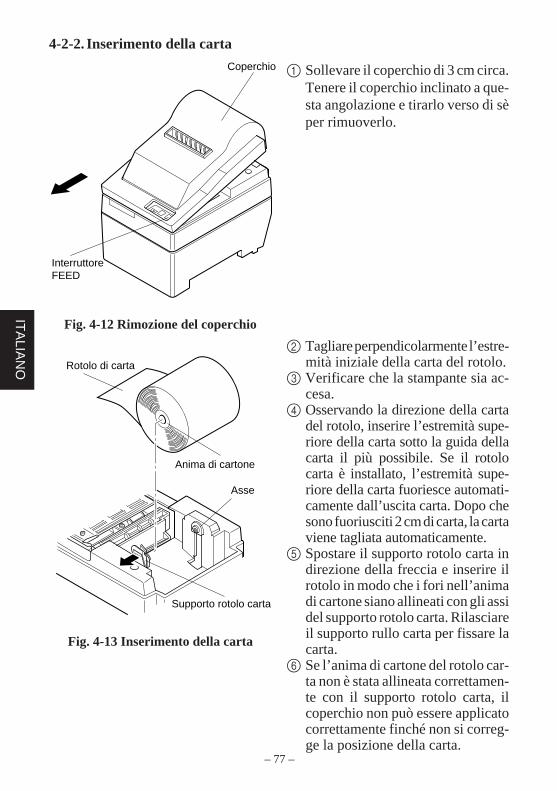
– 77 –
ITA
LIAN
O Rotolo di carta
Anima di cartone
Asse
Supporto rotolo carta
Coperchio
Interruttore FEED
4-2-2. Inserimento della carta
1 Sollevare il coperchio di 3 cm circa.Tenere il coperchio inclinato a que-sta angolazione e tirarlo verso di sèper rimuoverlo.
2 Tagliare perpendicolarmente l’estre-mità iniziale della carta del rotolo.
3 Verificare che la stampante sia ac-cesa.
4 Osservando la direzione della cartadel rotolo, inserire l’estremità supe-riore della carta sotto la guida dellacarta il più possibile. Se il rotolocarta è installato, l’estremità supe-riore della carta fuoriesce automati-camente dall’uscita carta. Dopo chesono fuoriusciti 2 cm di carta, la cartaviene tagliata automaticamente.
5 Spostare il supporto rotolo carta indirezione della freccia e inserire ilrotolo in modo che i fori nell’animadi cartone siano allineati con gli assidel supporto rotolo carta. Rilasciareil supporto rullo carta per fissare lacarta.
6 Se l’anima di cartone del rotolo car-ta non è stata allineata correttamen-te con il supporto rotolo carta, ilcoperchio non può essere applicatocorrettamente finché non si correg-ge la posizione della carta.
Fig. 4-12 Rimozione del coperchio
Fig. 4-13 Inserimento della carta
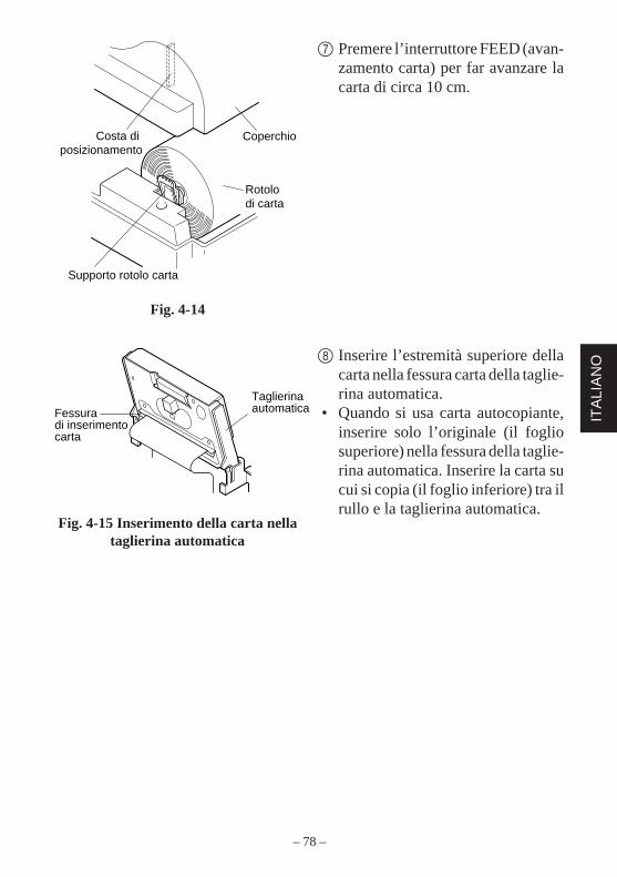
– 78 –
ITA
LIA
NO
Costa di posizionamento
Coperchio
Rotolo di carta
Supporto rotolo carta
7 Premere l’interruttore FEED (avan-zamento carta) per far avanzare lacarta di circa 10 cm.
8 Inserire l’estremità superiore dellacarta nella fessura carta della taglie-rina automatica.
• Quando si usa carta autocopiante,inserire solo l’originale (il fogliosuperiore) nella fessura della taglie-rina automatica. Inserire la carta sucui si copia (il foglio inferiore) tra ilrullo e la taglierina automatica.
Fig. 4-14
Fig. 4-15 Inserimento della carta nellataglierina automatica
Fessura di inserimento carta
Taglierina automatica
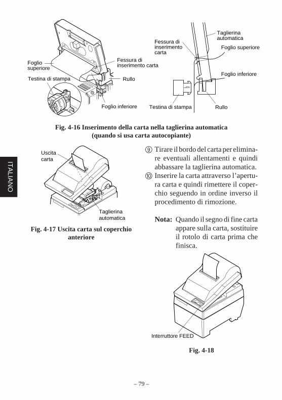
– 79 –
ITA
LIAN
O
Uscita carta
Taglierina automatica
Fig. 4-16 Inserimento della carta nella taglierina automatica(quando si usa carta autocopiante)
9 Tirare il bordo del carta per elimina-re eventuali allentamenti e quindiabbassare la taglierina automatica.
0 Inserire la carta attraverso l’apertu-ra carta e quindi rimettere il coper-chio seguendo in ordine inverso ilprocedimento di rimozione.
Nota: Quando il segno di fine cartaappare sulla carta, sostituireil rotolo di carta prima chefinisca.
Fig. 4-18
Fig. 4-17 Uscita carta sul coperchioanteriore
Interruttore FEED
Fessura di inserimento carta
Rullo
Foglio inferiore
Foglio superiore
Testina di stampa
Testina di stampa
Fessura di inserimento carta
Taglierina automatica
Rullo
Foglio inferiore
Foglio superiore
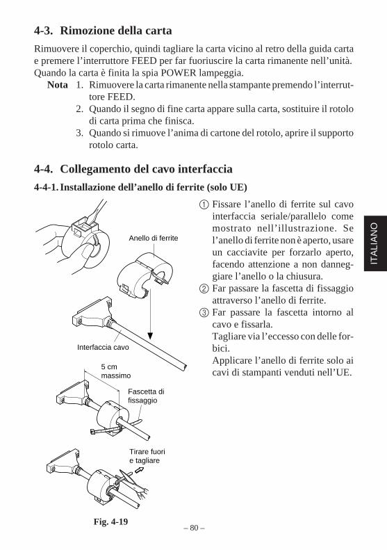
– 80 –
ITA
LIA
NO
Tirare fuori e tagliare
5 cm massimo
Fascetta di fissaggio
Anello di ferrite
Interfaccia cavo
4-3. Rimozione della carta
Rimuovere il coperchio, quindi tagliare la carta vicino al retro della guida cartae premere l’interruttore FEED per far fuoriuscire la carta rimanente nell’unità.Quando la carta è finita la spia POWER lampeggia.
Nota 1. Rimuovere la carta rimanente nella stampante premendo l’interrut-tore FEED.
2. Quando il segno di fine carta appare sulla carta, sostituire il rotolodi carta prima che finisca.
3. Quando si rimuove l’anima di cartone del rotolo, aprire il supportorotolo carta.
4-4. Collegamento del cavo interfaccia
4-4-1. Installazione dell’anello di ferrite (solo UE)
1 Fissare l’anello di ferrite sul cavointerfaccia seriale/parallelo comemostrato nell’illustrazione. Sel’anello di ferrite non è aperto, usareun cacciavite per forzarlo aperto,facendo attenzione a non danneg-giare l’anello o la chiusura.
2 Far passare la fascetta di fissaggioattraverso l’anello di ferrite.
3 Far passare la fascetta intorno alcavo e fissarla.Tagliare via l’eccesso con delle for-bici.Applicare l’anello di ferrite solo aicavi di stampanti venduti nell’UE.
Fig. 4-19

– 81 –
ITA
LIAN
O
Anello di ferrite(solo UE)
Anello di ferrite (solo UE)
Cacciavite
Viti
4-4-2. Cavo interfaccia seriale
1 Spegnere sia il computer ospite chela stampante.
2 Inserire il connettore ad un capo delcavo interfaccia nel connettore sul-la stampante e l’altro connettore nelconnettore sul computer ospite.
3 Fissare le viti destra e sinistra deirispettivi connettori interfaccia perfissare in posizione i connettori.
Fig. 4-20 Collegamento del cavointerfaccia
4-4-3. Cavo interfaccia parallelo
1 Spegnere sia il computer ospite chela stampante.
2 Inserire un terminale del cavointerfaccia nel connettore sulla stam-pante, come mostrato nella figura, efissarlo con il morsetto.
3 Inserire l’altro terminale del cavointerfaccia nel connettore sul com-puter ospite e fissare anche questocon il morsetto.
Fig. 4-21 Collegamento del cavointerfaccia parallelo
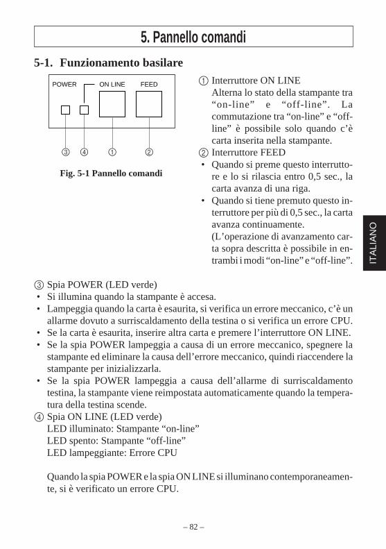
– 82 –
ITA
LIA
NO
5. Pannello comandi5-1. Funzionamento basilare
3 Spia POWER (LED verde)• Si illumina quando la stampante è accesa.• Lampeggia quando la carta è esaurita, si verifica un errore meccanico, c’è un
allarme dovuto a surriscaldamento della testina o si verifica un errore CPU.• Se la carta è esaurita, inserire altra carta e premere l’interruttore ON LINE.• Se la spia POWER lampeggia a causa di un errore meccanico, spegnere la
stampante ed eliminare la causa dell’errore meccanico, quindi riaccendere lastampante per inizializzarla.
• Se la spia POWER lampeggia a causa dell’allarme di surriscaldamentotestina, la stampante viene reimpostata automaticamente quando la tempera-tura della testina scende.
4 Spia ON LINE (LED verde)LED illuminato: Stampante “on-line”LED spento: Stampante “off-line”LED lampeggiante: Errore CPU
Quando la spia POWER e la spia ON LINE si illuminano contemporaneamen-te, si è verificato un errore CPU.
ON LINEPOWER FEED
3 4 1 2
Fig. 5-1 Pannello comandi
1 Interruttore ON LINEAlterna lo stato della stampante tra“on-line” e “off-line”. Lacommutazione tra “on-line” e “off-line” è possibile solo quando c’ècarta inserita nella stampante.
2 Interruttore FEED• Quando si preme questo interrutto-
re e lo si rilascia entro 0,5 sec., lacarta avanza di una riga.
• Quando si tiene premuto questo in-terruttore per più di 0,5 sec., la cartaavanza continuamente.(L’operazione di avanzamento car-ta sopra descritta è possibile in en-trambi i modi “on-line” e “off-line”.
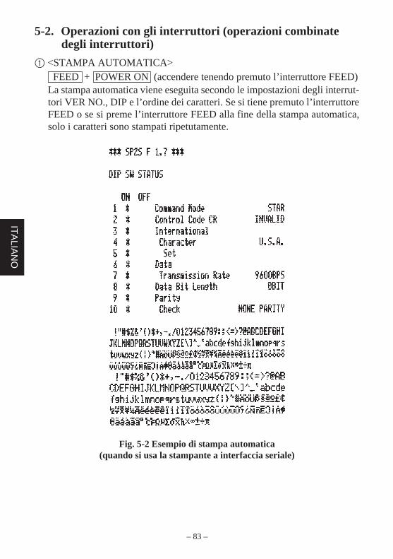
– 83 –
ITA
LIAN
O
5-2. Operazioni con gli interruttori (operazioni combinatedegli interruttori)
1 <STAMPA AUTOMATICA> FEED + POWER ON (accendere tenendo premuto l’interruttore FEED)La stampa automatica viene eseguita secondo le impostazioni degli interrut-tori VER NO., DIP e l’ordine dei caratteri. Se si tiene premuto l’interruttoreFEED o se si preme l’interruttore FEED alla fine della stampa automatica,solo i caratteri sono stampati ripetutamente.
Fig. 5-2 Esempio di stampa automatica(quando si usa la stampante a interfaccia seriale)
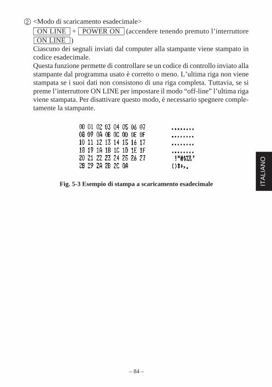
– 84 –
ITA
LIA
NO
2 <Modo di scaricamento esadecimale> ON LINE + POWER ON (accendere tenendo premuto l’interruttore ON LINE )Ciascuno dei segnali inviati dal computer alla stampante viene stampato incodice esadecimale.Questa funzione permette di controllare se un codice di controllo inviato allastampante dal programma usato è corretto o meno. L’ultima riga non vienestampata se i suoi dati non consistono di una riga completa. Tuttavia, se sipreme l’interruttore ON LINE per impostare il modo “off-line” l’ultima rigaviene stampata. Per disattivare questo modo, è necessario spegnere comple-tamente la stampante.
Fig. 5-3 Esempio di stampa a scaricamento esadecimale
– 85 –
ITA
LIAN
O
6. Codici di controlloModo STAR
6-1. Codici di controllo usati nell’impostazione dei caratteri
Codici di controllo Codici esadecimali Funzione
<ESC> “R” n 1B 52 n Seleziona il gruppo caratteri internazionale. Il defaultè in base all’impostazione degli interruttori Dip 3, 4e 5.
<ESC> “M” 1B 4D Seleziona il formato caratteri 7 × 7 (mezzi punti)(impostazione default)
<ESC> “P” 1B 50 Seleziona il formato caratteri 9 × 7 (mezzi punti)
<SO> 0E Seleziona il modo caratteri espanso
<SI> 0F Disattiva il modo caratteri espanso(impostazione default)
<DC4> 14 Disattiva il modo caratteri espanso(impostazione default)
<ESC> “W” “1” 1B 57 31 Seleziona il modo caratteri espanso<ESC> “W” <1> 1B 57 01
<ESC> “W” “0” 1B 57 30 Disattiva il modo caratteri espanso<ESC> “W” <0> 1B 57 00 (impostazione default)
6-2. Codici di controllo usati nell’impostazione del modo distampa
Codici di controllo Codici esadecimali Funzione
<ESC> “4” 1B 34 Selezione della stampa in colore rosso (abilitata perla SP216)
<ESC> “5” 1B 35 Deselezione della stampa in colore rosso (abilitataper la SP216) (impostazione default)
<ESC> “E” 1B 45 Selezione del modo stampa enfatizzata
<ESC> “F” 1B 46 Deselezione del modo stampa enfatizzata(impostazione default)
6-3. Codici di controllo usati nella spaziatura delle righe
Codici di controllo Codici esadecimali Funzione
<LF> 0A Avanzamento di riga
<CR> 0D Avanzamento di riga (come LF)
<ESC> “a” n 1B 61 n Avanzamento della carta di n righe
– 86 –
ITA
LIA
NO
6-4. Codici di controllo usati per unità periferiche
Codici di controllo Codici esadecimali Funzione
<ESC> <BEL> n1 n2 1B 07 n1 n2 Regola l’ampiezza degli impulsi di pilotaggio perl’unità periferica (impostazione default)
<BEL> 07 Comando di pilotaggio differito “A” per unità peri-ferica 1
<FS> 1C Comando di pilotaggio immediato “B” per unitàperiferica 1
6-5. Controllo della taglierina automatica (solo tipo SP240)
Codici di controllo Codici esadecimali Funzione
<ESC> “d” “0” 1B 64 30 Comando di taglio completo alla taglierina<ESC> “d” <0> 1B 64 00 automatica
<ESC> “d” “1” 1B 64 31 Comando di taglio parziale alla taglierina<ESC> “d” <1> 1B 64 01 automatica
6-6. Altri codici di controllo
Codici di controllo Codici esadecimali Funzione
<CAN> 18 Cancella i dati di stampa nel buffer
<ESC> “@” 1B 40 Inizializza la stampante
<ESC> “e” “0” 1B 65 30 Interruttore ON LINE/FEED valido<ESC> “e” <0> 1B 65 00 (impostazione default)
<ESC> “e” “1” 1B 65 31 Interruttore ON LINE/FEED non valido<ESC> “e” <1> 1B 65 01
<ESC> “f” “0” 1B 66 30 Interruttore ON LINE valido<ESC> “f” <0> 1B 66 00 (impostazione default)
<ESC> “f” “1” 1B 66 31 Interruttore ON LINE non valido<ESC> “f” <1> 1B 66 01
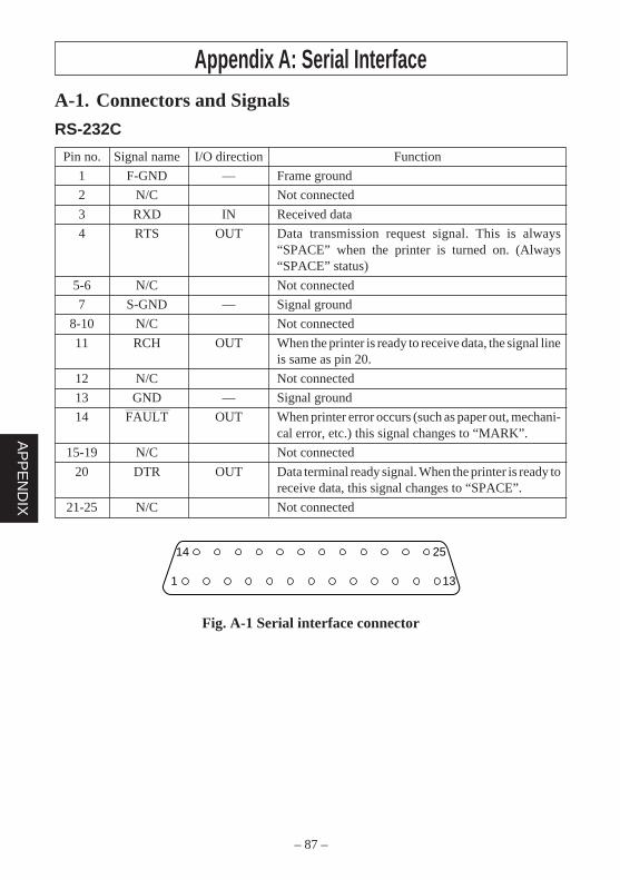
– 87 –
AP
PE
ND
IX
Appendix A: Serial Interface
14
1 13
25
A-1. Connectors and Signals
RS-232C
Pin no. Signal name I/O direction Function
1 F-GND — Frame ground
2 N/C Not connected
3 RXD IN Received data
4 RTS OUT Data transmission request signal. This is always“SPACE” when the printer is turned on. (Always“SPACE” status)
5-6 N/C Not connected
7 S-GND — Signal ground
8-10 N/C Not connected
11 RCH OUT When the printer is ready to receive data, the signal lineis same as pin 20.
12 N/C Not connected
13 GND — Signal ground
14 FAULT OUT When printer error occurs (such as paper out, mechani-cal error, etc.) this signal changes to “MARK”.
15-19 N/C Not connected
20 DTR OUT Data terminal ready signal. When the printer is ready toreceive data, this signal changes to “SPACE”.
21-25 N/C Not connected
Fig. A-1 Serial interface connector
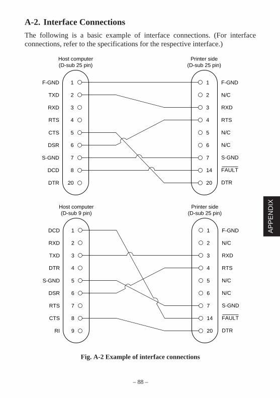
– 88 –
AP
PE
ND
IX
A-2. Interface Connections
The following is a basic example of interface connections. (For interfaceconnections, refer to the specifications for the respective interface.)
Fig. A-2 Example of interface connections
1 F-GND
N/C
RXD
RTS
N/C
N/C
S-GND
FAULT
DTR
F-GND
2TXD
3RXD
4RTS
5CTS
6DSR
7S-GND
8DCD
20
1
2
3
4
5
6
7
14
20DTR
Host computer(D-sub 25 pin)
Printer side(D-sub 25 pin)
1 F-GND
N/C
RXD
RTS
N/C
N/C
S-GND
FAULT
DTR
DCD
2RXD
3TXD
4DTR
5S-GND
6DSR
7RTS
8CTS
9
1
2
3
4
5
6
7
14
20RI
Host computer(D-sub 9 pin)
Printer side(D-sub 25 pin)
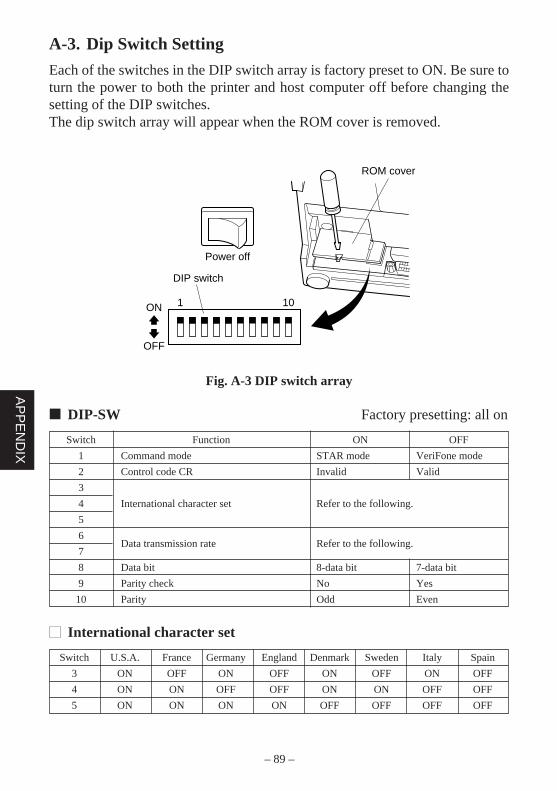
– 89 –
AP
PE
ND
IX
A-3. Dip Switch Setting
Each of the switches in the DIP switch array is factory preset to ON. Be sure toturn the power to both the printer and host computer off before changing thesetting of the DIP switches.The dip switch array will appear when the ROM cover is removed.
Fig. A-3 DIP switch array
DIP-SW Factory presetting: all on
Switch Function ON OFF
1 Command mode STAR mode VeriFone mode
2 Control code CR Invalid Valid
3
4 International character set Refer to the following.
5
6Data transmission rate Refer to the following.
7
8 Data bit 8-data bit 7-data bit
9 Parity check No Yes
10 Parity Odd Even
International character set
Switch U.S.A. France Germany England Denmark Sweden Italy Spain
3 ON OFF ON OFF ON OFF ON OFF
4 ON ON OFF OFF ON ON OFF OFF
5 ON ON ON ON OFF OFF OFF OFF
101ON
OFF
DIP switch
Power off
ROM cover
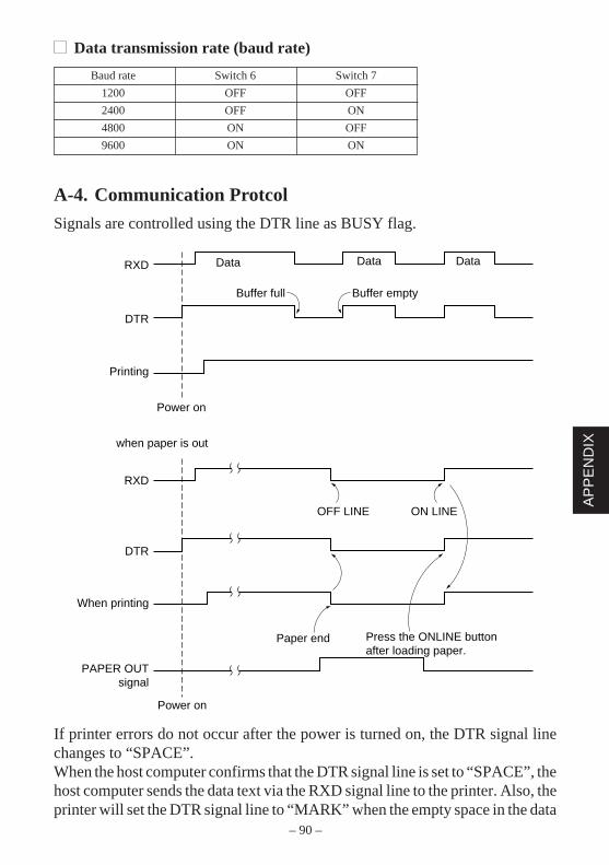
– 90 –
AP
PE
ND
IX
Data transmission rate (baud rate)
Baud rate Switch 6 Switch 7
1200 OFF OFF
2400 OFF ON
4800 ON OFF
9600 ON ON
A-4. Communication Protcol
Signals are controlled using the DTR line as BUSY flag.
If printer errors do not occur after the power is turned on, the DTR signal linechanges to “SPACE”.When the host computer confirms that the DTR signal line is set to “SPACE”, thehost computer sends the data text via the RXD signal line to the printer. Also, theprinter will set the DTR signal line to “MARK” when the empty space in the data
RXD
DTR
Printing
Data Data Data
Buffer full Buffer empty
Power on
when paper is out
RXD
DTR
OFF LINE ON LINE
When printing
PAPER OUTsignal
Power on
Paper end Press the ONLINE buttonafter loading paper.
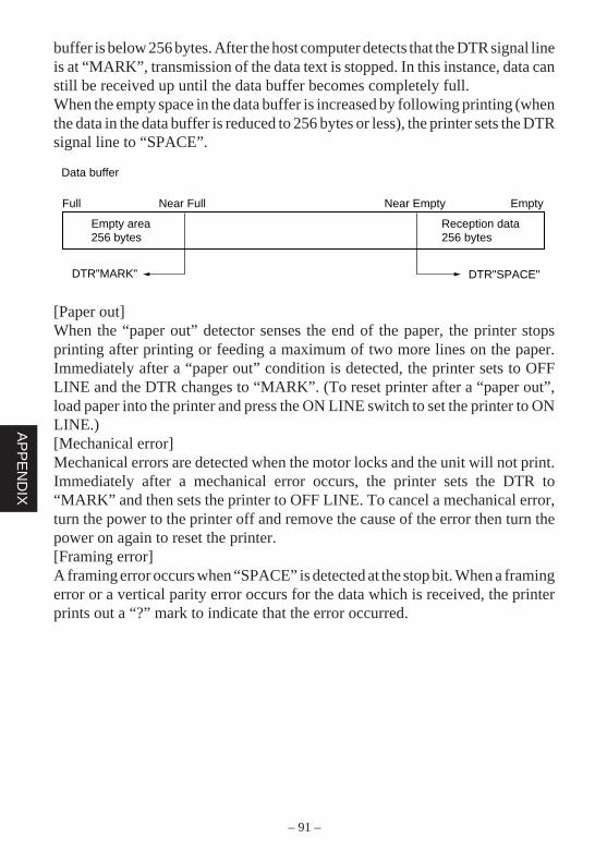
– 91 –
AP
PE
ND
IX
buffer is below 256 bytes. After the host computer detects that the DTR signal lineis at “MARK”, transmission of the data text is stopped. In this instance, data canstill be received up until the data buffer becomes completely full.When the empty space in the data buffer is increased by following printing (whenthe data in the data buffer is reduced to 256 bytes or less), the printer sets the DTRsignal line to “SPACE”.
[Paper out]When the “paper out” detector senses the end of the paper, the printer stopsprinting after printing or feeding a maximum of two more lines on the paper.Immediately after a “paper out” condition is detected, the printer sets to OFFLINE and the DTR changes to “MARK”. (To reset printer after a “paper out”,load paper into the printer and press the ON LINE switch to set the printer to ONLINE.)[Mechanical error]Mechanical errors are detected when the motor locks and the unit will not print.Immediately after a mechanical error occurs, the printer sets the DTR to“MARK” and then sets the printer to OFF LINE. To cancel a mechanical error,turn the power to the printer off and remove the cause of the error then turn thepower on again to reset the printer.[Framing error]A framing error occurs when “SPACE” is detected at the stop bit. When a framingerror or a vertical parity error occurs for the data which is received, the printerprints out a “?” mark to indicate that the error occurred.
Data buffer
Full Near Full
Empty area256 bytes
DTR"MARK"
Near Empty Empty
Reception data256 bytes
DTR"SPACE"
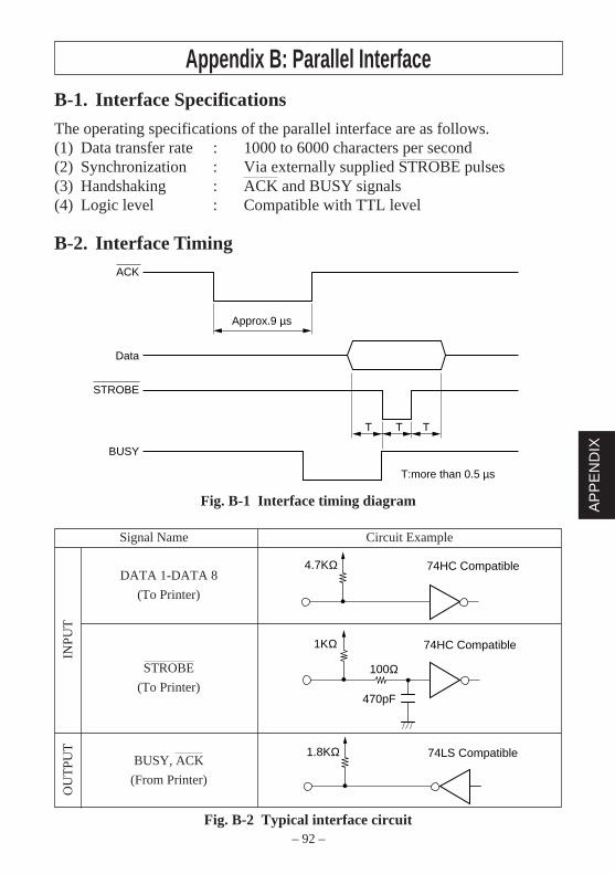
– 92 –
AP
PE
ND
IX
Appendix B: Parallel InterfaceB-1. Interface Specifications
The operating specifications of the parallel interface are as follows.(1) Data transfer rate : 1000 to 6000 characters per second(2) Synchronization : Via externally supplied STROBE pulses(3) Handshaking : ACK and BUSY signals(4) Logic level : Compatible with TTL level
B-2. Interface Timing
Fig. B-1 Interface timing diagram
Signal Name Circuit Example
DATA 1-DATA 8
(To Printer)
STROBE
(To Printer)
BUSY, ACK
(From Printer)
Fig. B-2 Typical interface circuit
ACK
Approx.9 µs
Data
STROBE
BUSY
T T T
T:more than 0.5 µs
74HC Compatible4.7KΩ
100Ω
470pF
74HC Compatible1KΩ
1.8KΩ 74LS Compatible
INP
UT
OU
TP
UT
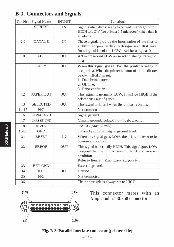
– 93 –
AP
PE
ND
IX
B-3. Connectors and SignalsPin No. Signal Name IN/OUT Function
1 STROBE IN Signals when data is ready to be read. Signal goes fromHIGH to LOW (for at least 0.5 microsec.) when data isavailable.
2-9 DATA1-8 IN These signals provide the information of the first toeighth bits of parallel data. Each signal is at HIGH levelfor a logical 1 and at a LOW level for a logical 0.
10 ACK OUT A 9 microsecond LOW pulse acknowledges receipt ofdata.
11 BUSY OUT When this signal goes LOW, the printer is ready toaccept data. When the printer is in one of the conditionsbelow. “HIGH” is set.1. Data being entered.2. Off line.3. Error condition.
12 PAPER OUT OUT This signal is normally LOW. It will go HIGH if theprinter runs out of paper.
13 SELECTED OUT This signal is HIGH when the printer is online.
14-15 N/C Not connected
16 SIGNAL GND Signal ground.
17 CHASSIS GND Chassis ground, isolated from logic ground.
18 +5VDC +5VDC (Max 50 mA)
19-30 GND Twisted pair return signal ground level.
31 RESET IN When this signal goes LOW, the printer is reset to itspower-on condition.
32 ERROR OUT This signal is normally HIGH. This signal goes LOWto signal that the printer cannot print due to an errorcondition.Refer to Item 8-4 Emergency Suspension.
33 EXT GND External ground.
34 OUT1 OUT Unused.
35 N/C Not connected
36 The printer side is always set to HIGH.
This connector mates with anAmphenol 57-30360 connector
Fig. B-3. Parallel interface connector (printer side)
(19) (36)
(1) (18)
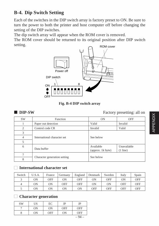
– 94 –
AP
PE
ND
IX
B-4. Dip Switch Setting
Each of the switches in the DIP switch array is factory preset to ON. Be sure toturn the power to both the printer and host computer off before changing thesetting of the DIP switches.The dip switch array will appear when the ROM cover is removed.The ROM cover should be returned to its original position after DIP switchsetting.
Fig. B-4 DIP switch array
DIP-SW Factory presetting: all on
SW Function ON OFF
1 Paper out detection Valid Invalid
2 Control code CR Invalid Valid
3
4 International character set See below
5
6Data buffer
Available Unavailable(approx. 1k byte) (1 line)
7Character generation setting See below
8
International character set
Switch U.S.A. France Germany England Denmark Sweden Italy Spain
3 ON OFF ON OFF ON OFF ON OFF
4 ON ON OFF OFF ON ON OFF OFF
5 ON ON ON ON OFF OFF OFF OFF
Character generation
SW US EC JP JP
7 ON ON OFF OFF
8 ON OFF ON OFF
81ON
OFF
DIP switch
Power off
ROM cover
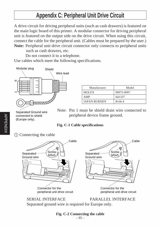
– 95 –
AP
PE
ND
IX
Appendix C: Peripheral Unit Drive CircuitA drive circuit for driving peripheral units (such as cash drawers) is featured onthe main logic board of this printer. A modular connector for driving peripheralunit is featured on the output side on the drive circuit. When using this circuit,connect the cable for the peripheral unit. (Cables must be prepared by the user.)Note: Peripheral unit drive circuit connector only connects to peripheral units
such as cash drawers, etc.Do not connect it to a telephone.
Use cables which meet the following specifications.
Note: Pin 1 must be shield drain wire connected toperipheral device frame ground.
Fig. C-1 Cable specifications
1 Connecting the cable
SERIAL INTERFACE PARALLEL INTERFACESeparated ground wire is required for Europe only.
Fig. C-2 Connecting the cable
16
Modular plug
Wire lead
Separated Ground wireconnected to shield (Europe only).
Shield
Manufacturer Model
MOLEX 90075-0007
AMP 641337
JAPAN BURNDY B-66-4
Cable
SeparatedGround wire
Connector for theperipheral unit drive circuit
ScrewM3x5
Cable
SeparatedGround wire
Connector for theperipheral unit drive circuit
ScrewM3x5
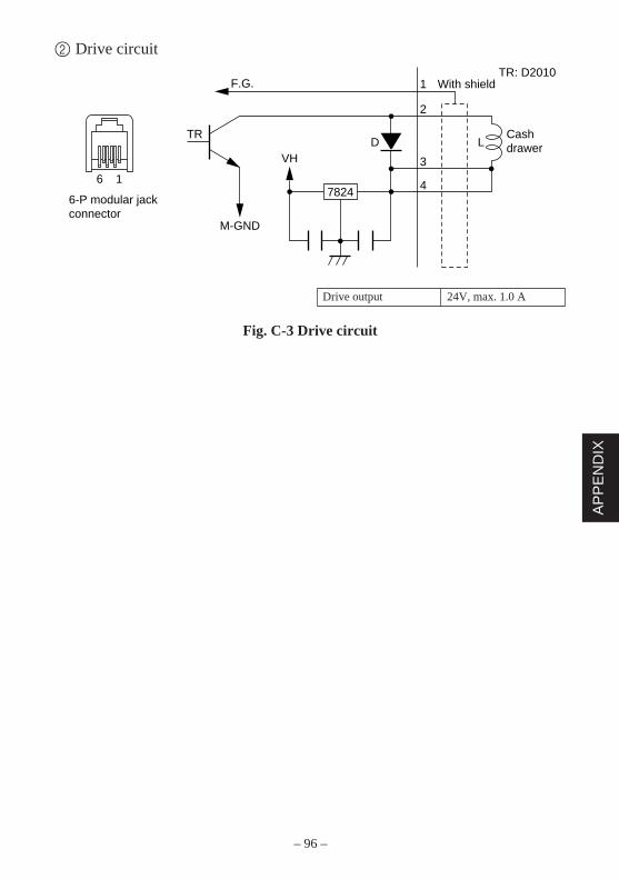
– 96 –
AP
PE
ND
IX
2 Drive circuit
Fig. C-3 Drive circuit
Drive output 24V, max. 1.0 A
1 With shield
Cashdrawer
TR: D2010
2
LDVH
7824
TR
M-GND
F.G.
3
46
6-P modular jackconnector
1
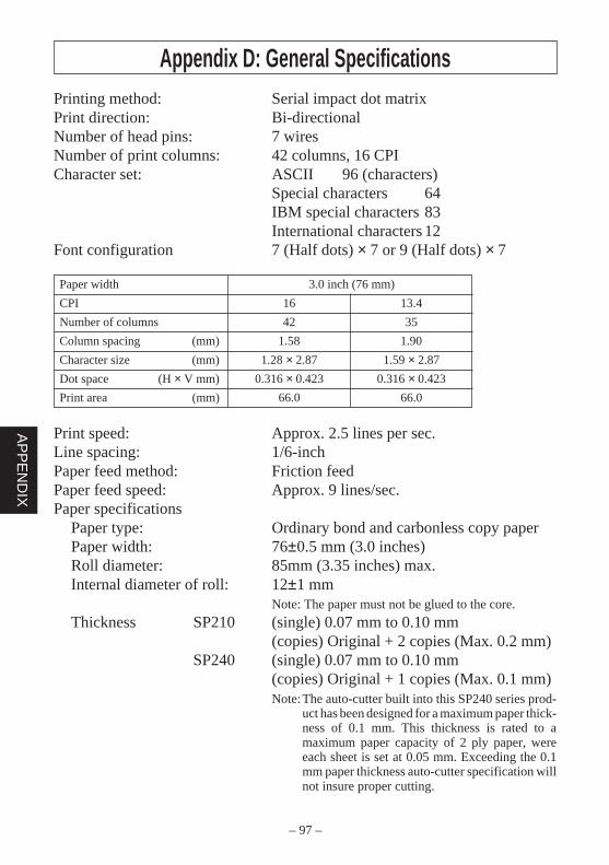
– 97 –
AP
PE
ND
IX
Appendix D: General SpecificationsPrinting method: Serial impact dot matrixPrint direction: Bi-directionalNumber of head pins: 7 wiresNumber of print columns: 42 columns, 16 CPICharacter set: ASCII 96 (characters)
Special characters 64IBM special characters 83International characters 12
Font configuration 7 (Half dots) × 7 or 9 (Half dots) × 7
Paper width 3.0 inch (76 mm)
CPI 16 13.4
Number of columns 42 35
Column spacing (mm) 1.58 1.90
Character size (mm) 1.28 × 2.87 1.59 × 2.87
Dot space (H × V mm) 0.316 × 0.423 0.316 × 0.423
Print area (mm) 66.0 66.0
Print speed: Approx. 2.5 lines per sec.Line spacing: 1/6-inchPaper feed method: Friction feedPaper feed speed: Approx. 9 lines/sec.Paper specifications
Paper type: Ordinary bond and carbonless copy paperPaper width: 76±0.5 mm (3.0 inches)Roll diameter: 85mm (3.35 inches) max.Internal diameter of roll: 12±1 mm
Note: The paper must not be glued to the core.
Thickness SP210 (single) 0.07 mm to 0.10 mm(copies) Original + 2 copies (Max. 0.2 mm)
SP240 (single) 0.07 mm to 0.10 mm(copies) Original + 1 copies (Max. 0.1 mm)Note:The auto-cutter built into this SP240 series prod-
uct has been designed for a maximum paper thick-ness of 0.1 mm. This thickness is rated to amaximum paper capacity of 2 ply paper, wereeach sheet is set at 0.05 mm. Exceeding the 0.1mm paper thickness auto-cutter specification willnot insure proper cutting.
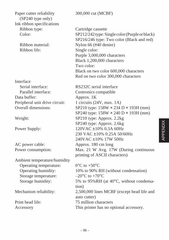
– 98 –
AP
PE
ND
IX
Paper cutter reliability 300,000 cut (MCBF)(SP240 type only)
Ink ribbon specificationsRibbon type: Cartridge cassetteColor: SP212/242 type: Single color (Purple or black)
SP216/246 type: Two color (Black and red)Ribbon material: Nylon 66 (#40 denier)Ribbon life: Single color:
Purple 3,000,000 charactersBlack 1,200,000 charactersTwo color:Black on two color 600,000 charactersRed on two color 300,000 characters
InterfaceSerial interface: RS232C serial interfaceParallel interface: Centronics compatible
Data buffer: Approx. 1KPeripheral unit drive circuit: 1 circuits (24V, max. 1A)Overall dimensions: SP210 type: 158W × 234 D × 193H (mm)
SP240 type: 158W × 240 D × 193H (mm)Weight: SP210 type: Approx. 2.2kg
SP240 type: Approx. 2.6kgPower Supply: 120VAC ±10% 0.3A 60Hz
230 VAC ±10% 0.25A 50/60Hz240VAC ±10% 17W 50Hz
AC power cable: Approx. 180 cm longPower consumption: Max. 21 W Avg. 17W (During continuous
printing of ASCII characters)Ambient temperature/humidity
Operating temperature: 0°C to +50°COperating humidity: 10% to 90% RH (without condensation)Storage temperature: –20°C to +70°CStorage humidity: 5% to 95%RH (at 40°C, without condensa-
tion)Mechanism reliability: 2,500,000 lines MCBF (except head life and
auto cutter)Print head life: 75 million charactersAccessory This printer has no optional accessory.
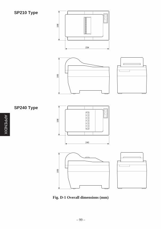
– 99 –
AP
PE
ND
IX
234
158
193
240
158
193
SP210 Type
SP240 Type
Fig. D-1 Overall dimensions (mm)
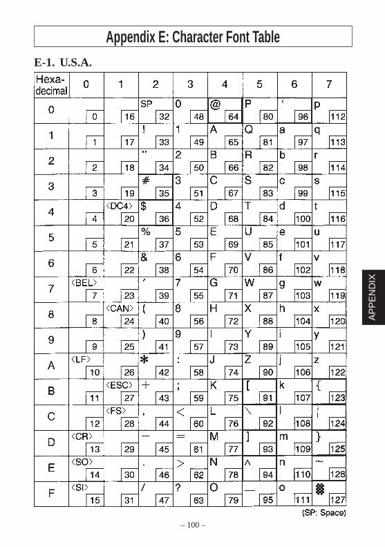
– 100 –
AP
PE
ND
IX
Appendix E: Character Font TableE-1. U.S.A.
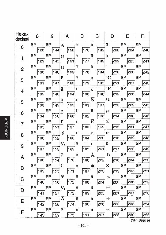
– 101 –
AP
PE
ND
IX
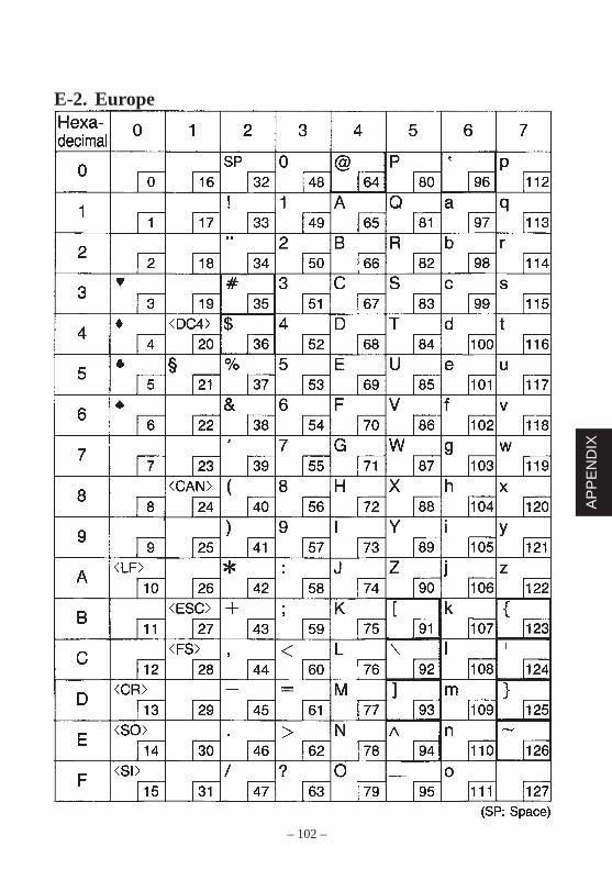
– 102 –
AP
PE
ND
IX
E-2. Europe

– 103 –
AP
PE
ND
IX
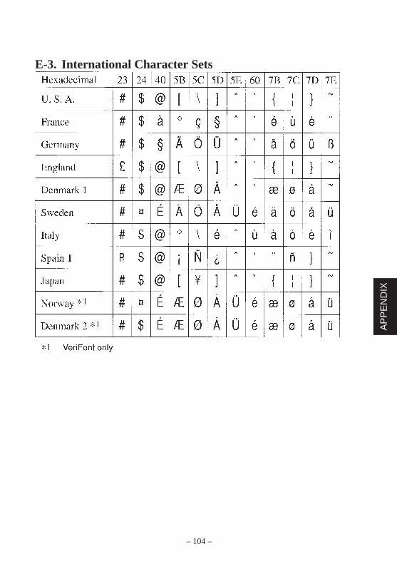
– 104 –
AP
PE
ND
IX
E-3. International Character Sets
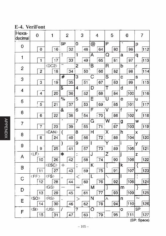
– 105 –
AP
PE
ND
IX
E-4. VeriFont
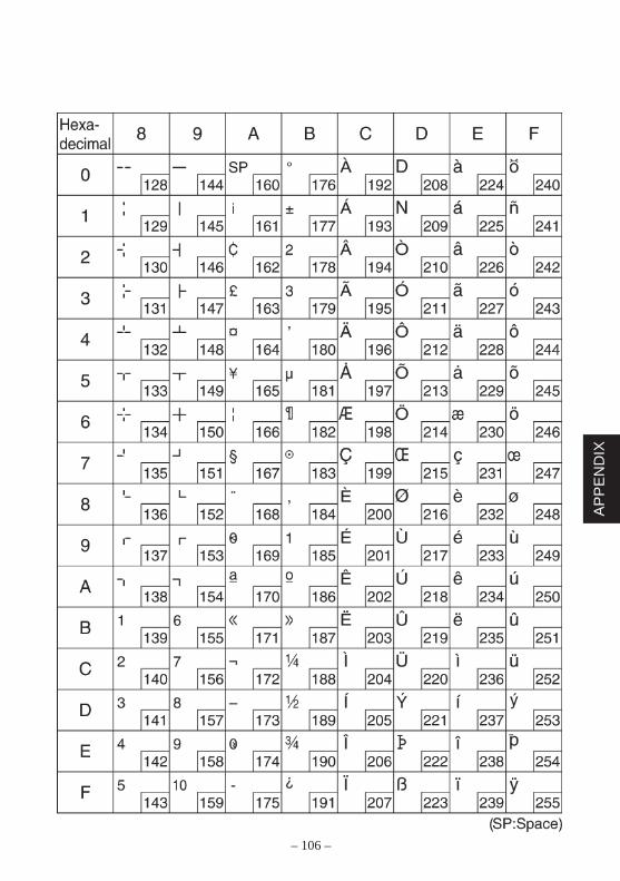
– 106 –
AP
PE
ND
IX


ELECTRONIC PRODUCTS DIVISIONSTAR MICRONICS CO., LTD.536 Nanatsushinnya, Shimizu, Shizuoka,424-0066 JapanTel: 0543-47-0112, Fax: 0543-48-5271
Please access the following URLhttp://www.star-micronics.co.jp/service/sp_sup_e.htmfor the lastest revision of the manual.
OVERSEAS SUBSIDIARY COMPANIESSTAR MICRONICS AMERICA, INC.1150 King Georges Post Road, Edison, NJ 08837-3729 U.S.A.Tel: 732-623-5555, Fax: 732-623-5590
STAR MICRONICS U.K. LTD.Star House, Peregrine Business Park, Gomm Road,High Wycombe, Bucks, HP13 7DL, U.K.Tel: 01494-471111, Fax: 01494-473333
2002.12.30Printed in Japan, 80870057