Embed Size (px)
Citation preview
1 of 4
CB1
DOSING PUMP Nyva SERIES- Hydraulic Single Diaphragm
| SEKO S.p.A. Technical data can be changed without notice. TD_CB1_Std_rev.4.0
Nyva series includes hydraulic diaphragm dosing pumps designed according to API 675 Standards; the conformity to the API Standards implies a “heavy duty” design, high safety and severe controls during the performance tests. The broad variety of heads execution offers a wide selection of dosing pumps to cover practically any application needs.
Mechanism
The mechanism is mechanical return type, giving the maximum reliability in all working conditions.
General Specifications:
• Low noise integral gearbox, worm type, oil bath lubricated • Reduced energy consumption based on low friction rolling bearings design • Micrometric stroke lenght adjustment both manually or automatically actuated. • Automatic stroke length variation by electrical servomotor, on request. • Easy “on field” installation of electrical servomotor on manual stroke adjustment mechanism. Diaphragm Pumphead
• Easy to change spares parts • Maximum compatibility PTFE diaphragm
Technical characteristics
• Flow rates: from 18 to 660 lph @ 50Hz
• Max Pressure: 12,4 MPa (124 bar) for 316L version
• Ambient temperature: -10 °C + 40 °C
• Max altitude: 1000 m (A.S.L.)
• Fluid operating temperature: -5 °C + 50 °C
• Viscosity up to 1000 mPa•s (1000 cP)
• Stroke adjustment during operation from 0 to 100%
• Accuracy ± 1 % on the turndown ratio 10:1
• Built-in overpressure valve
• Single diaphragm
• Diaphragm duration up to 20.000 hours, depending of the
application
• CE marking
• Electric motor protection: IP 55
• Epoxy painting at 125 micron
2 of 4
CB1
DOSING PUMP Nyva SERIES- Hydraulic Single Diaphragm
| SEKO S.p.A. Technical data can be changed without notice. TD_CB1_Std_rev.4.0
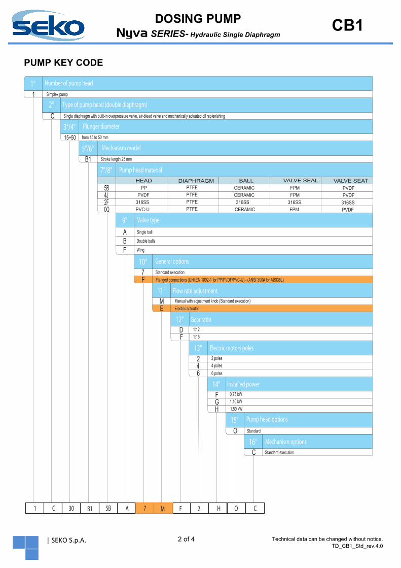
PUMP KEY CODE
1°1
Number of pump headSimplex pump
2°Codice Type of pump head (double diaphragm)C
Plunger diameter
2°
3°/4°from 15 to 50 mm
5°/6° Mechanism modelB1 Stroke length 25 mm
7°/8° Pump head material
15÷50
9°AB
Single ball
Double balls
Valve type
10° General options7 Standard execution
11° Flow rate adjustmentM Manual with adjustment knob (Standard execution)
12° Gear ratio
13° Electric motors poles246
2 poles4 poles6 poles
14° Installed power
15° Pump head options
C16°
Standard execution
Mechanism options
1 C 30 B1 5B A 7 M H
Single diaphragm with built-in overpressure valve, air-bleed valve and mechanically actuated oil replenishing
VALVE SEATVALVE SEALHEAD BALLDIAPHRAGM
2F 316SS PTFE 316SS 316SS 316SS
O C
O Standard
E Electric actuator
F Flanged connections (UNI EN 1092-1 for PP/PVDF/PVC-U) - (ANSI 300# for AISI36L)
1,50 kWH
5B PP PTFE CERAMIC FPM PVDF4J PVDF PTFE CERAMIC FPM PVDF
0Q PVC-U PTFE CERAMIC FPM PVDF
DF
1:121:15
FG
0,75 kW1,10 kW
F 2
F Wing
3 of 4
CB1
DOSING PUMP Nyva SERIES- Hydraulic Single Diaphragm
| SEKO S.p.A. Technical data can be changed without notice. TD_CB1_Std_rev.4.0
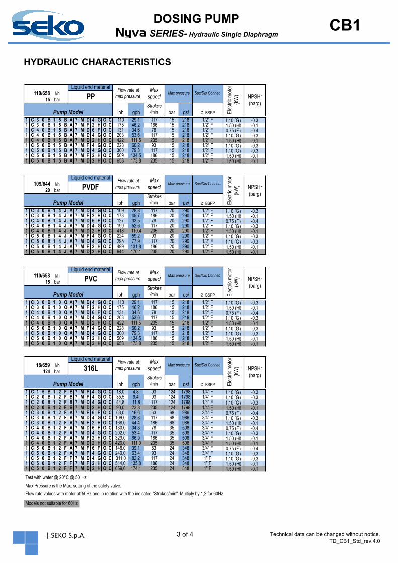
HYDRAULIC CHARACTERISTICS
lph gphStrokes
/min bar psi Ø BSPP1 C 3 0 B 1 5 B A 7 M D 4 G O C 110 29,1 117 15 218 1/2" F 1,10 (G) -0,31 C 3 0 B 1 5 B A 7 M F 2 H O C 175 46,2 186 15 218 1/2" F 1,50 (H) -0,11 C 4 0 B 1 5 B A 7 M D 6 F O C 131 34,6 78 15 218 1/2" F 0,75 (F) -0,41 C 4 0 B 1 5 B A 7 M D 4 G O C 203 53,6 117 15 218 1/2" F 1,10 (G) -0,31 C 4 0 B 1 5 B A 7 M D 2 H O C 422 111,5 235 15 218 1/2" F 1,50 (H) -0,11 C 5 0 B 1 5 B A 7 M F 4 G O C 228 60,2 93 15 218 1/2" F 1,10 (G) -0,31 C 5 0 B 1 5 B A 7 M D 4 G O C 300 79,3 117 15 218 1/2" F 1,10 (G) -0,31 C 5 0 B 1 5 B A 7 M F 2 H O C 509 134,5 186 15 218 1/2" F 1,50 (H) -0,11 C 5 0 B 1 5 B A 7 M D 2 H O C 658 173,8 235 15 218 1/2" F 1,50 (H) -0,1
lph gphStrokes
/min bar psi Ø BSPP1 C 3 0 B 1 4 J A 7 M D 4 G O C 109 28,8 117 20 290 1/2" F 1,10 (G) -0,31 C 3 0 B 1 4 J A 7 M F 2 H O C 173 45,7 186 20 290 1/2" F 1,50 (H) -0,11 C 4 0 B 1 4 J A 7 M D 6 F O C 127 33,5 78 20 290 1/2" F 0,75 (F) -0,41 C 4 0 B 1 4 J A 7 M D 4 G O C 199 52,6 117 20 290 1/2" F 1,10 (G) -0,31 C 4 0 B 1 4 J A 7 M D 2 H O C 418 110,4 235 20 290 1/2" F 1,50 (H) -0,11 C 5 0 B 1 4 J A 7 M F 4 G O C 224 59,2 93 20 290 1/2" F 1,10 (G) -0,31 C 5 0 B 1 4 J A 7 M D 4 G O C 295 77,9 117 20 290 1/2" F 1,10 (G) -0,31 C 5 0 B 1 4 J A 7 M F 2 H O C 499 131,8 186 20 290 1/2" F 1,50 (H) -0,11 C 5 0 B 1 4 J A 7 M D 2 H O C 644 170,1 235 20 290 1/2" F 1,50 (H) -0,1
lph gphStrokes
/min bar psi Ø BSPP1 C 3 0 B 1 0 Q A 7 M D 4 G O C 110 29,1 117 15 218 1/2" F 1,10 (G) -0,31 C 3 0 B 1 0 Q A 7 M F 2 H O C 175 46,2 186 15 218 1/2" F 1,50 (H) -0,11 C 4 0 B 1 0 Q A 7 M D 6 F O C 131 34,6 78 15 218 1/2" F 0,75 (F) -0,41 C 4 0 B 1 0 Q A 7 M D 4 G O C 203 53,6 117 15 218 1/2" F 1,10 (G) -0,31 C 4 0 B 1 0 Q A 7 M D 2 H O C 422 111,5 235 15 218 1/2" F 1,50 (H) -0,11 C 5 0 B 1 0 Q A 7 M F 4 G O C 228 60,2 93 15 218 1/2" F 1,10 (G) -0,31 C 5 0 B 1 0 Q A 7 M D 4 G O C 300 79,3 117 15 218 1/2" F 1,10 (G) -0,31 C 5 0 B 1 0 Q A 7 M F 2 H O C 509 134,5 186 15 218 1/2" F 1,50 (H) -0,11 C 5 0 B 1 0 Q A 7 M D 2 H O C 658 173,8 235 15 218 1/2" F 1,50 (H) -0,1
lph gphStrokes
/min bar psi Ø BSPP1 C 1 5 B 1 2 F B 7 M F 4 G O C 18,0 4,8 93 124 1798 1/4" F 1,10 (G) -0,31 C 2 0 B 1 2 F B 7 M F 4 G O C 35,5 9,4 93 124 1798 1/4" F 1,10 (G) -0,31 C 2 0 B 1 2 F B 7 M D 4 G O C 44,8 11,8 117 124 1798 1/4" F 1,10 (G) -0,31 C 2 0 B 1 2 F B 7 M D 2 H O C 90,0 23,8 235 124 1798 1/4" F 1,50 (H) -0,11 C 3 0 B 1 2 F A 7 M F 6 F O C 63,0 16,6 63 68 986 3/4" F 0,75 (F) -0,41 C 3 0 B 1 2 F A 7 M D 4 G O C 109,0 28,8 117 68 986 3/4" F 1,10 (G) -0,31 C 3 0 B 1 2 F A 7 M F 2 H O C 168,0 44,4 186 68 986 3/4" F 1,50 (H) -0,11 C 4 0 B 1 2 F A 7 M D 6 F O C 130,0 34,3 78 35 508 3/4" F 0,75 (F) -0,41 C 4 0 B 1 2 F A 7 M D 4 G O C 202,0 53,4 117 35 508 3/4" F 1,10 (G) -0,31 C 4 0 B 1 2 F A 7 M F 2 H O C 329,0 86,9 186 35 508 3/4" F 1,50 (H) -0,11 C 4 0 B 1 2 F A 7 M D 2 H O C 420,0 111,0 235 35 508 3/4" F 1,50 (H) -0,11 C 5 0 B 1 2 F A 7 M F 6 F O C 148,0 39,1 63 24 348 3/4" F 0,75 (F) -0,41 C 5 0 B 1 2 F A 7 M F 4 G O C 240,0 63,4 93 24 348 3/4" F 1,10 (G) -0,31 C 5 0 B 1 2 F F 7 M D 4 G O C 311,0 82,2 117 24 348 1" F 1,10 (G) -0,31 C 5 0 B 1 2 F F 7 M F 2 H O C 514,0 135,8 186 24 348 1" F 1,50 (H) -0,11 C 5 0 B 1 2 F F 7 M D 2 H O C 659,0 174,1 235 24 348 1" F 1,50 (H) -0,1
Max Pressure is the Max. setting of the safety valve.Flow rate values with motor at 50Hz and in relation with the indicated "Strokes/min". Multiply by 1,2 for 60Hz
Max pressure
Pump Model
Max speed
Liquid end material
PP
Pump Model
15110/658 l/h
bar NPSHr (barg)
Elec
tric m
otor
(k
W) NPSHr
(barg)
18/659 l/h 316L124 bar
Elec
tric m
otor
(k
W)Suc/Dis Connec
Flow rate at max pressure
Liquid end material Flow rate at max pressure
Max speed
Max pressure Suc/Dis Connec
Elec
tric m
otor
(k
W)
Suc/Dis Connec
110/658 l/h PVC15 bar
Pump Model
Elec
tric m
otor
(k
W) NPSHr
(barg)bar
Pump Model
Liquid end material Flow rate at max pressure
Max speed
Max pressure Suc/Dis ConnecNPSHr (barg)
Models not suitable for 60Hz
Test with water @ 20°C @ 50 Hz.
Liquid end material Flow rate at max pressure
Max speed
Max pressure109/644 l/h PVDF20
4 of 4
CB1
DOSING PUMP Nyva SERIES- Hydraulic Single Diaphragm
| SEKO S.p.A. Technical data can be changed without notice. TD_CB1_Std_rev.4.0
min300
min.150min.150 min.150min.150
min
.150
approx.50
approx.50
102.5
340
E
225
(17)
351 (STROKE 0%)
301 (STROKE 100%)
61approx.
357
THREAD A
C B
ADJUSTEMENTKNOB
STANDARDELECTRIC MOTOR
EARTHINGM8
OVERPRESSUREVALVE
MECHANISMOIL DISCHARGE
MECHANISMOIL CHARGE
OIL SIGHT
DISCHARGE
SUCTION
A
OPT
ION
AL F
LAN
GE:
PP/P
VDF/
PVC
- LJ F
ALN
GE
100
316L
- LJ
FALN
GE
50
OPT
ION
AL F
LAN
GE:
PP/P
VDF/
PVC
- LJ F
ALN
GE
100
316L
- LJ
FALN
GE
50
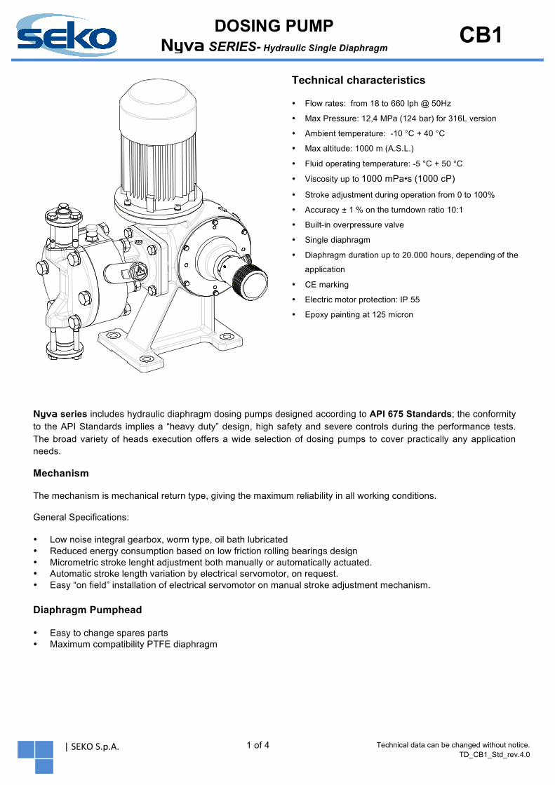
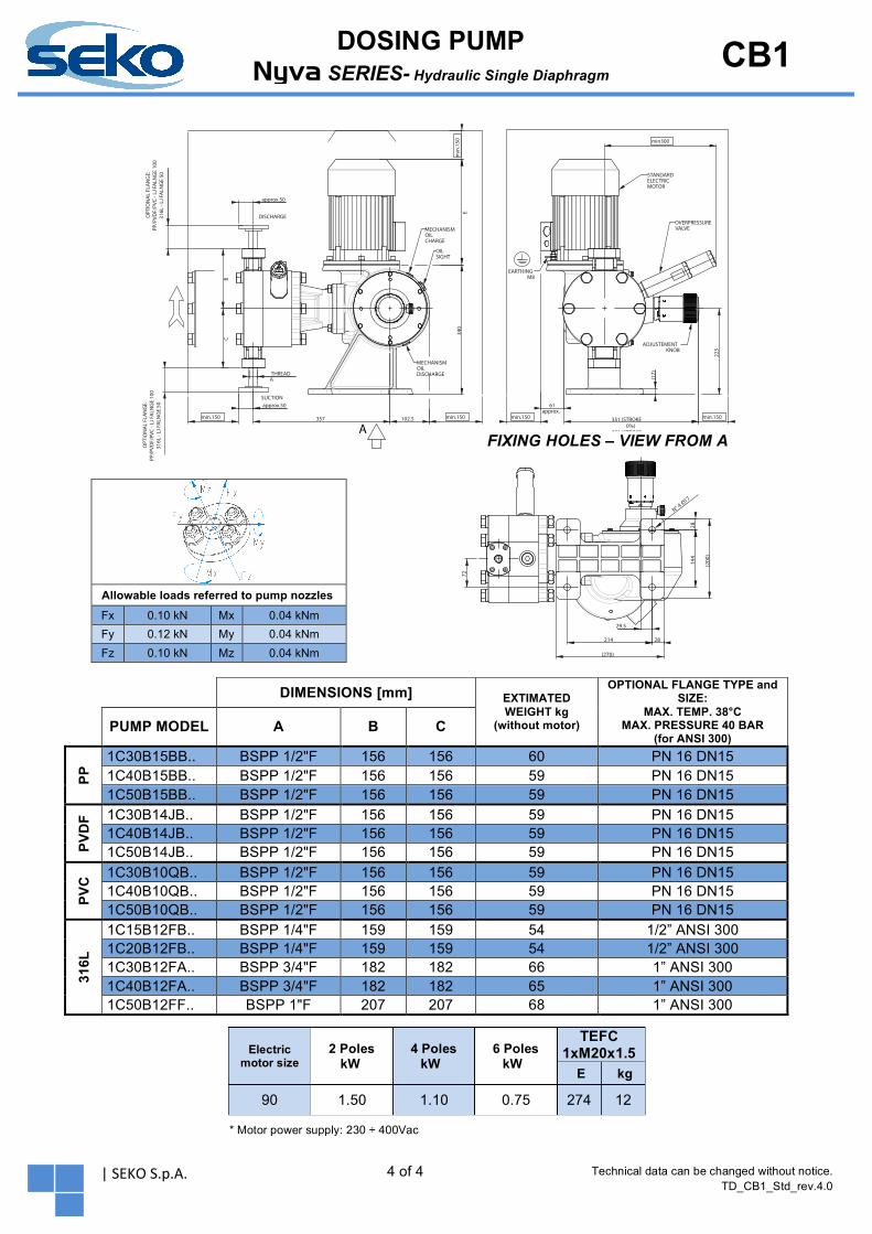
Allowable loads referred to pump nozzles Fx 0.10 kN Mx 0.04 kNm Fy 0.12 kN My 0.04 kNm Fz 0.10 kN Mz 0.04 kNm
DIMENSIONS [mm] EXTIMATED WEIGHT kg
(without motor)
OPTIONAL FLANGE TYPE and SIZE:
MAX. TEMP. 38°C MAX. PRESSURE 40 BAR
(for ANSI 300)
PUMP MODEL A B C
PP 1C30B15BB.. BSPP 1/2"F 156 156 60 PN 16 DN15
1C40B15BB.. BSPP 1/2"F 156 156 59 PN 16 DN15 1C50B15BB.. BSPP 1/2"F 156 156 59 PN 16 DN15
PVD
F 1C30B14JB.. BSPP 1/2"F 156 156 59 PN 16 DN15 1C40B14JB.. BSPP 1/2"F 156 156 59 PN 16 DN15 1C50B14JB.. BSPP 1/2"F 156 156 59 PN 16 DN15
PVC
1C30B10QB.. BSPP 1/2"F 156 156 59 PN 16 DN15 1C40B10QB.. BSPP 1/2"F 156 156 59 PN 16 DN15 1C50B10QB.. BSPP 1/2"F 156 156 59 PN 16 DN15
316L
1C15B12FB.. BSPP 1/4"F 159 159 54 1/2” ANSI 300 1C20B12FB.. BSPP 1/4"F 159 159 54 1/2” ANSI 300 1C30B12FA.. BSPP 3/4"F 182 182 66 1” ANSI 300 1C40B12FA.. BSPP 3/4"F 182 182 65 1” ANSI 300 1C50B12FF.. BSPP 1"F 207 207 68 1” ANSI 300
FIXING HOLES – VIEW FROM A
Electric motor size
2 Poles kW
4 Poles kW
6 Poles kW
TEFC 1xM20x1.5
E kg
90 1.50 1.10 0.75 274 12
* Motor power supply: 230 ÷ 400Vac
214
29.5
(200
)
(270)
72
28
28
144
N° 4 1
7O