Embed Size (px)
Citation preview

Recommended Standards and Guidance for Performance, Application, Design, and Operation & Maintenance
Dosing Gravity Drainfield Systems
July 2012

Recommended Standards and Guidance for Performance, Application, Design, and Operation & Maintenance
Dosing Gravity Drainfield Systems July 2012
For information or additional copies of this report contact: Wastewater Management Program Physical address: 111 Israel Rd SE, Tumwater, WA 98501 Mailing address: PO Box 47824, Olympia, WA 98504-7824 Phone: (360) 236-3330 FAX: (360) 236-2257 Email: [email protected] Mary Selecky Secretary of Health For persons with disabilities, this document is available upon request in other formats. To submit a request, please call 1-888-586-9427 (TDD/TTY 1-800-833-6388). Para personas discapacitadas, este documento está disponible a su pedido en otros formatos. Para hacer su pedido llame al 1-888-586-9427 (TDD/TTY 1-800-833-6388). DOH Publication #337-004
Dosing Gravity Drainfield Systems - Recommended Standards and Guidance Effective Date: July 1, 2012
DOH 37-004 Page 3 of 17
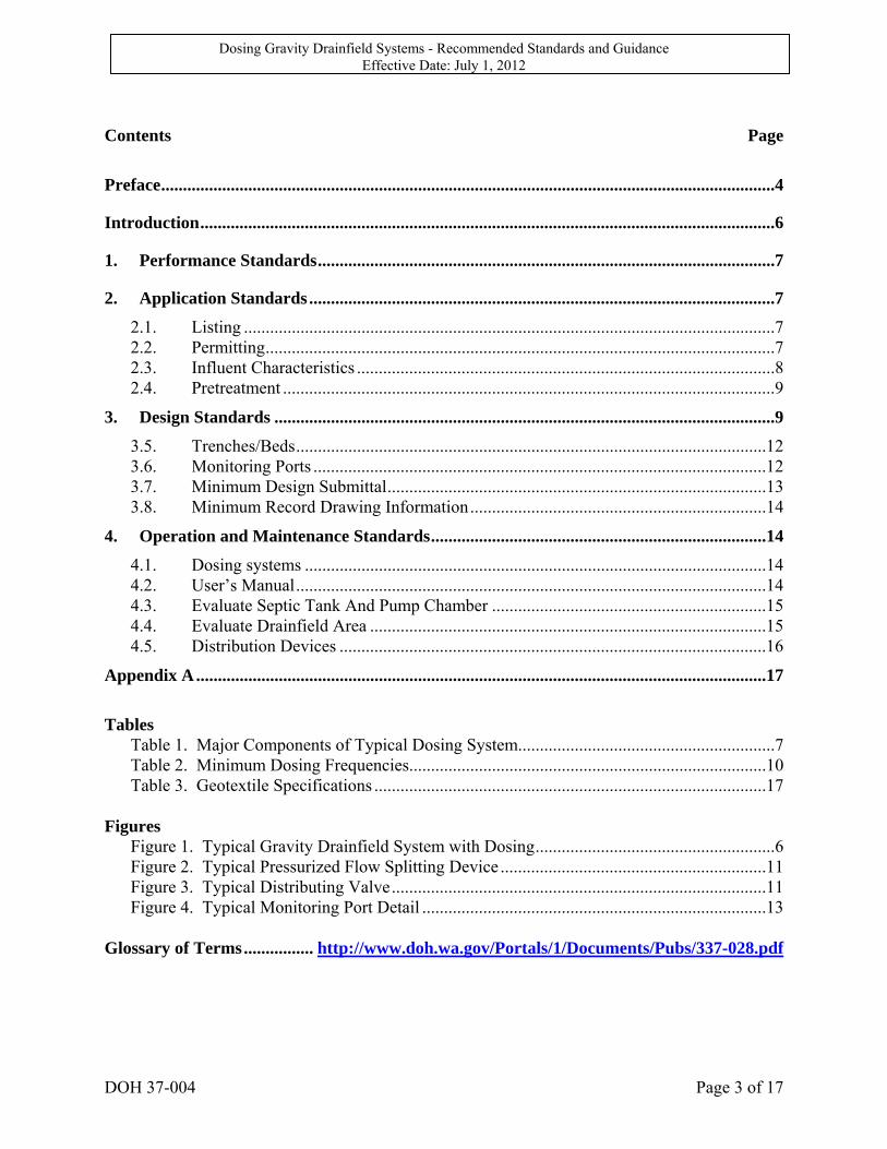
Contents Page
Preface .............................................................................................................................................4
Introduction ....................................................................................................................................6
1. Performance Standards .........................................................................................................7
2. Application Standards ...........................................................................................................7
2.1. Listing ..........................................................................................................................7 2.2. Permitting .....................................................................................................................7 2.3. Influent Characteristics ................................................................................................8 2.4. Pretreatment .................................................................................................................9
3. Design Standards ...................................................................................................................9
3.5. Trenches/Beds ............................................................................................................12 3.6. Monitoring Ports ........................................................................................................12 3.7. Minimum Design Submittal .......................................................................................13 3.8. Minimum Record Drawing Information ....................................................................14
4. Operation and Maintenance Standards .............................................................................14
4.1. Dosing systems ..........................................................................................................14 4.2. User’s Manual ............................................................................................................14 4.3. Evaluate Septic Tank And Pump Chamber ...............................................................15 4.4. Evaluate Drainfield Area ...........................................................................................15 4.5. Distribution Devices ..................................................................................................16
Appendix A ...................................................................................................................................17
Tables
Table 1. Major Components of Typical Dosing System...........................................................7 Table 2. Minimum Dosing Frequencies..................................................................................10 Table 3. Geotextile Specifications ..........................................................................................17
Figures
Figure 1. Typical Gravity Drainfield System with Dosing .......................................................6 Figure 2. Typical Pressurized Flow Splitting Device .............................................................11 Figure 3. Typical Distributing Valve ......................................................................................11 Figure 4. Typical Monitoring Port Detail ...............................................................................13
Glossary of Terms ................ http://www.doh.wa.gov/Portals/1/Documents/Pubs/337-028.pdf
Dosing Gravity Drainfield Systems - Recommended Standards and Guidance Effective Date: July 1, 2012
DOH 37-004 Page 4 of 17
Preface The recommended standards contained in this document have been developed for statewide application. Regional differences may, however, result in application of this technology in a manner different than it is presented here. In some localities, greater allowances than those described here may reasonably be granted. In other localities, allowances that are provided for in this document may be restricted. In either setting, the local health officer has full authority in the application of this technology, consistent with Chapter 246-272A WAC and local jurisdictional rules. If any provision of these recommended standards is inconsistent with local jurisdictional rules, regulations, ordinances, policies, procedures, or practices, the local standards take precedence. Application of the recommended standards presented here is at the full discretion of the local health officer. Local jurisdictional application of these recommended standards may be: 1) Adopted as part of local rules, regulations or ordinances - When the recommended
standards, either as they are written or modified to more accurately reflect local conditions, are adopted as part of the local rules, their application is governed by local rule authority.
2) Referred to as technical guidance in the application of the technology - The
recommended standards, either as they are written or modified to more accurately reflect local conditions, may be used locally as technical guidance.
Application of these recommended standards may occur in a manner that combines these two approaches. How these recommended standards are applied at the local jurisdictional level remains at the discretion of the local health officer and the local board of health. The recommended standards presented here are provided in typical rule language to assist those local jurisdictions where adoption in local rules is the preferred option. Other information and guidance is presented in text boxes with a modified font style to easily distinguish it from the recommended standards. Glossary of Terms: A glossary of common terms for all RS&Gs can be found on the DOH Web site at http://www.doh.wa.gov/Portals/1/Documents/Pubs/337-028.pdf. The recommended standards contained in this document have been primarily written to support the design of on-site sewage systems with design flows less than 3500 gpd, but may also be applied to large on-site sewage systems (LOSS). With the adoption of the revised LOSS rule, chapter 246-272B WAC, in 2011, some provisions of the RS&Gs may not be appropriate or allowed for LOSS. Many applicable requirements from the RS&Gs have already been included in the LOSS rule. Design engineers and others interested in LOSS are directed to consult the rule and LOSS program staff before or instead of the RS&Gs.

Dosing Gravity Drainfield Systems - Recommended Standards and Guidance Effective Date: July 1, 2012
DOH 37-004 Page 5 of 17
Typical RS&G Organization:
Standards Section Explanation
Performance How this technology is expected to perform (treatment level and function)
Application How this technology is to be applied. This section includes conditions that must be met prior to proceeding with design. Topics in this section describe the “approved” status of the technology, component listing requirements, permitting, installation, testing and inspection requirements, etc.
Design How this technology is to be designed and constructed (includes minimum standards that must be met to obtain a permit).
Operation and Maintenance How this technology is to be operated and maintained (includes responsibilities of various parties, recommended maintenance tasks and frequency, assurance measures, etc)
Appendices Design examples, figures and tables, specific applications, and design and installation issues, and bibliography.
Dosing Gravity Drainfield Systems - Recommended Standards and Guidance Effective Date: July 1, 2012
DOH 37-004 Page 6 of 17
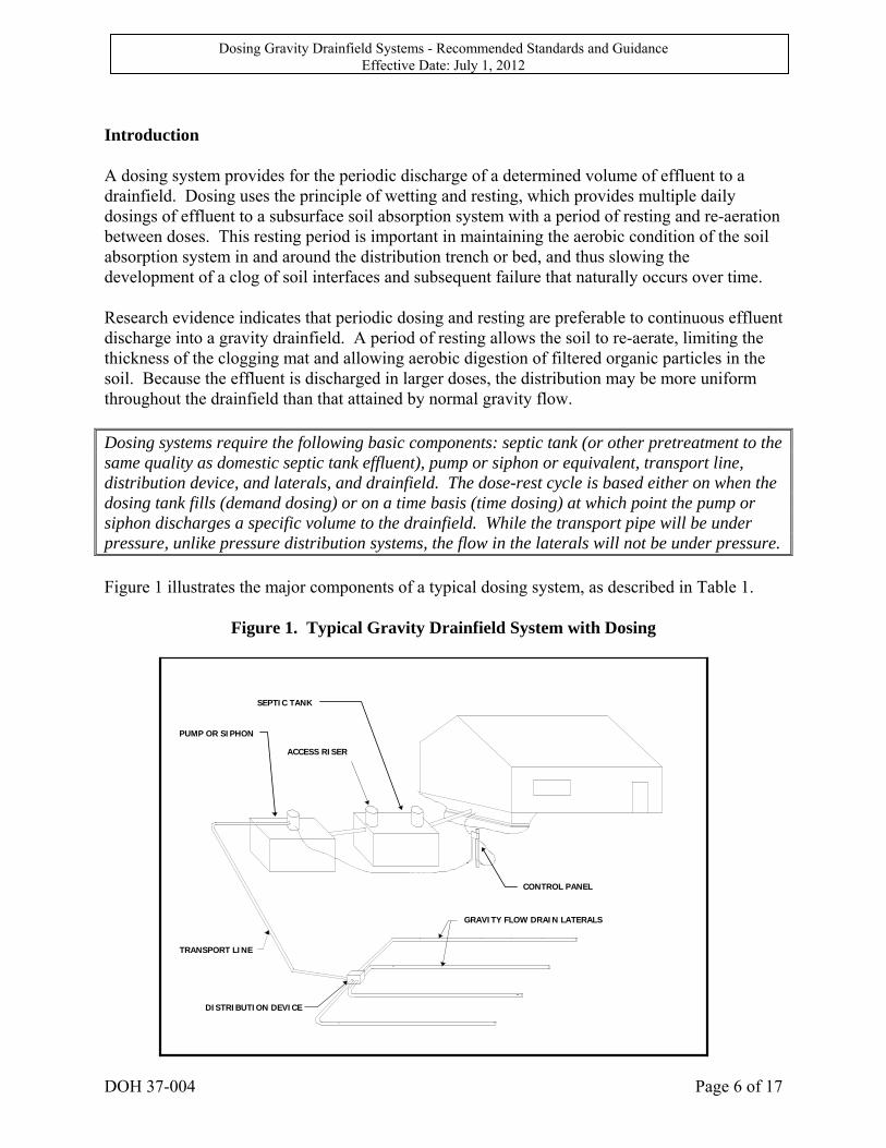
Introduction A dosing system provides for the periodic discharge of a determined volume of effluent to a drainfield. Dosing uses the principle of wetting and resting, which provides multiple daily dosings of effluent to a subsurface soil absorption system with a period of resting and re-aeration between doses. This resting period is important in maintaining the aerobic condition of the soil absorption system in and around the distribution trench or bed, and thus slowing the development of a clog of soil interfaces and subsequent failure that naturally occurs over time. Research evidence indicates that periodic dosing and resting are preferable to continuous effluent discharge into a gravity drainfield. A period of resting allows the soil to re-aerate, limiting the thickness of the clogging mat and allowing aerobic digestion of filtered organic particles in the soil. Because the effluent is discharged in larger doses, the distribution may be more uniform throughout the drainfield than that attained by normal gravity flow. Dosing systems require the following basic components: septic tank (or other pretreatment to the same quality as domestic septic tank effluent), pump or siphon or equivalent, transport line, distribution device, and laterals, and drainfield. The dose-rest cycle is based either on when the dosing tank fills (demand dosing) or on a time basis (time dosing) at which point the pump or siphon discharges a specific volume to the drainfield. While the transport pipe will be under pressure, unlike pressure distribution systems, the flow in the laterals will not be under pressure. Figure 1 illustrates the major components of a typical dosing system, as described in Table 1.
Figure 1. Typical Gravity Drainfield System with Dosing
CONTROL PANEL
SEPTIC TANK
PUMP OR SIPHON
ACCESS RISER
GRAVITY FLOW DRAIN LATERALS
DISTRIBUTION DEVICE
TRANSPORT LINE
Dosing Gravity Drainfield Systems - Recommended Standards and Guidance Effective Date: July 1, 2012
DOH 37-004 Page 7 of 17
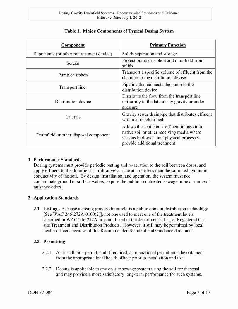
Table 1. Major Components of Typical Dosing System
Component Primary Function
Septic tank (or other pretreatment device) Solids separation and storage
Screen Protect pump or siphon and drainfield from solids
Pump or siphon Transport a specific volume of effluent from the chamber to the distribution devise
Transport line Pipeline that connects the pump to the distribution device
Distribution device Distribute the flow from the transport line uniformly to the laterals by gravity or under pressure
Laterals Gravity sewer drainpipe that distributes effluent within a trench or bed
Drainfield or other disposal component
Allows the septic tank effluent to pass into native soil or other receiving media where various biological and physical processes provide additional treatment
1. Performance Standards
Dosing systems must provide periodic resting and re-aeration to the soil between doses, and apply effluent to the drainfield’s infiltrative surface at a rate less than the saturated hydraulic conductivity of the soil. By design, installation, and operation, the system must not contaminate ground or surface waters, expose the public to untreated sewage or be a source of nuisance odors.
2. Application Standards
2.1. Listing - Because a dosing gravity drainfield is a public domain distribution technology [See WAC 246-272A-0100(2)], not one used to meet one of the treatment levels specified in WAC 246-272A, it is not listed in the department’s List of Registered On-site Treatment and Distribution Products. However, it still may be permitted by local health officers because of this Recommended Standard and Guidance document.
2.2. Permitting
2.2.1. An installation permit, and if required, an operational permit must be obtained
from the appropriate local health officer prior to installation and use.
2.2.2. Dosing is applicable to any on-site sewage system using the soil for disposal and may provide a more satisfactory long-term performance for such systems.
Dosing Gravity Drainfield Systems - Recommended Standards and Guidance Effective Date: July 1, 2012
DOH 37-004 Page 8 of 17
Dosing systems are most appropriate where the intermittent application of effluent will assist in either the treatment or disposal of effluent. Soil with slow permeability will benefit the most. Possible applications include:
2.2.2.1. For use in a subsurface soil absorption system (drainfield), where a
pressure distribution design is not required, and where continuous gravity flow is not feasible or desirable.
2.2.2.2. For systems with design flows less than 1000 gallons per day.
2.2.2.3. For drainfields with laterals less than one hundred feet in length.
2.2.2.4. For sites where vertical separation of 3 feet or greater can be maintained (dosing septic tank effluent).
2.2.2.5. For systems in any conventional drainfield design where the soils are of
an acceptable permeability and depth, except that systems are not allowed in sites where the soils are of an excessively permeable nature (Type 1 or 2 soils) unless:
2.2.2.5.1. A pre-treatment system meeting Treatment Level A or B is used, or 2.2.2.5.2. A method of uniform distribution is used.
Dosing systems are usually used in locations where it is either desirable or required to: install the drainfield at a higher elevation than the septic tank; treat and dispose of effluent higher in the soil profile; and extend the life expectancy of a drainfield or other disposal component.
2.3. Influent Characteristics
2.3.1. Residential Wastewater: Dosing systems are designed for treating residential
strength wastewater. The wastewater applied to drainfields must not be higher in strength than 125 mg/l CBOD5, 80 mg/l TSS, and 20 mg/l G&O. Lower wastewater strengths, without increased flow rates are preferable for assuring long term operation of a dosing system.
2.3.2. Non-Residential Wastewater: High-strength wastewater and wastewater from
non-domestic sources (such as restaurants, hotels, bed and breakfast establishments, and commercial wastewater sources, etc.) must be individually evaluated for treatability and degree of pretreatment required prior to distribution to the dosing system for final treatment and disposal.
Dosing Gravity Drainfield Systems - Recommended Standards and Guidance Effective Date: July 1, 2012
DOH 37-004 Page 9 of 17
2.4. Pretreatment
2.4.1. If the wastewater is residential sewage, settleable and floatable solid separation
by a properly sized two-compartment septic tank with effluent baffle screening will suffice. All septic tanks must be designed in compliance with Washington State On-Site Sewage System Regulations (WAC 246-272A and WAC 246-272B) and the Recommended Standards and Guidance for On-site Sewage System Tanks. Pretreatment with some other approved sedimentation/initial treatment unit may be used instead of a septic tank.
2.4.2. If the wastewater is from a non-domestic source, influent to the dosing system
must be equivalent to residential strength septic tank effluent or lower. Aerobic treatment or some other treatment process may be needed to modify the influent to the dosing system to within the range of residential septic tank effluent quality.
3. Design Standards
3.1. Pump Chamber Requirements - All pump chambers must be structurally sound and conform to WAC 246-272A, WAC 246-272B, and the Recommended Standards and Guidance for On-site Sewage System Tanks.
3.2. Pumps, Fittings and Controls - Pumps must be selected to pump effluent and be
capable of meeting the minimum hydraulic flow and head requirements of the proposed on-site system. All pumps, fittings, and controls must meet the minimum applicable requirements found in the Recommended Standards and Guidance for Pressure Distribution Systems.
Dosing can be achieved by either a pump or siphon. Where the soil absorption area is at a higher elevation than the pump, sufficient dynamic head should be provided for both the elevation difference and friction loss. Pumps suitable for pumping sewage effluent must be used. In lieu of pumps, automatic dosing siphons may be used for dosing where a suitable downhill gradient exists from the elevation of the siphon to the drainfield. Careful consideration must be given to manufacturer’s specifications during design and installation of automatic siphons.
3.3. Minimum Dose Frequency - The volume of each dose is dependent on the type of soil
in which the drainfield will be installed. The minimum dosing frequency must be according to Table 2:

Dosing Gravity Drainfield Systems - Recommended Standards and Guidance Effective Date: July 1, 2012
DOH 37-004 Page 10 of 17
Table 2. Minimum Dosing Frequencies
Soil Type Minimum Number of Doses/Day
1 Gravity system not allowed
2 < 60 inches vertical separation – gravity system not allowed
≥60 inches vertical separation = 4
3 < 36 inches vertical separation – gravity system not allowed
≥ 36 inches vertical separation = 4
4-6 < 36 inches vertical separation – gravity system not allowed
≥ 36 inches vertical separation = 1 or 2
3.4. Distribution Techniques
3.4.1. Effluent distribution may be accomplished by the use of commercially available
pressurized flow splitter devices, distributing valves, or by conventional distribution boxes. All distribution devices shall be of sound construction, watertight, not subject to excessive corrosion, and designed for its intended use. They must be placed at a high point so that flow is by gravity in all lines following the device. They must be fitted with risers and watertight lids or covers, extending to grade, which will permit unobstructed access for maintenance, inspection, and operation.
3.4.2. Distribution boxes must be installed level to assure that each lateral in the
drainfield is receiving an equivalent amount of effluent. Measures must be taken to dissipate the velocity of the influent delivered by a pump or siphon, and to prevent direct flow of effluent across the distribution box resulting in unequal distribution among the outlets.
Although the purpose of the distribution box is to divide effluent flows evenly among drainfield laterals, it is not an efficient or effective method of achieving equal flow splitting. The distribution box should be placed on a concrete pad or otherwise solidly anchored to prevent it from tilting or shifting in place. The use of commercially available outlet pipe leveling devices can compensate in elevation differences in outlets and facilitate leveling adjustments. Because of their constant radius and ease of adjustment, these devices may improve the accuracy with which a box can be leveled initially and in the future.
3.4.3. A pressurized flow splitting device such as a pressure manifold may create the
most uniform distribution of the distribution devices, regardless of the drainfield lateral length or elevation. Fitting the manifold with orifices sized to permit the percentage of flow desired accommodates different lengths of laterals. An air-

Dosing Gravity Drainfield Systems - Recommended Standards and Guidance Effective Date: July 1, 2012
DOH 37-004 Page 11 of 17
release valve (swing-check valve installed in reverse) located at the high point(s) is required if siphoning can occur through the device. Figure 2 shows an example of a pressurized flow splitting device.
Figure 2. Typical Pressurized Flow Splitting Device
3.4.4. Distributing valves can be used as a means for distributing effluent to multiple drainfield laterals or zones. The water pressures in the transport line activate these valves. Each time the pump is turned on, the valve rotates to dose the next drainfield. Figure 3 shows a distributing valve assembly. Distributing valves must be designed with the following features:
3.4.4.1. Unions to allow easy removal of the valve.
Figure 3. Typical Distributing Valve
Dosing Gravity Drainfield Systems - Recommended Standards and Guidance Effective Date: July 1, 2012
DOH 37-004 Page 12 of 17
3.4.4.2. Clear sections of pipe for visual inspection of valve operation.
3.4.4.3. A ball valve on the inlet for quick testing of valve operation. The best location of the distributing valve for reliable operation is at the high point in the system. The transport line between the pump and valve should be kept full if possible. If the line is empty at the beginning of each cycle, pockets of air during filling can cause random rotation of the valve. To minimize air pockets, the transport line between the pump and valve should be kept full, short, and (most important) laid at a constant grade. Because of the mechanical movements of these valves, it is necessary to take steps to prevent solids from reaching the valve, which may impede operation. Without adequate septic tank effluent screening, the valve has very little chance of reliable long-term operation. Installation of the valve should not be considered unless a system monitoring program is required for inspecting the valve on a routine frequency. Inspections are necessary to prevent system failure if the valve stops working properly. Because liquid flow through a distributing valve passes fairly small openings with several changes in direction, head losses through the valve are high. To assure enough head is available for proper system operation, it is recommended that high head turbine pumps be used to pressurize the valve. High pressures through the valve provide a large force for proper seating of the rubber flap disk, thus lowering the leakage that can occur through the openings that are not being pressurized. High head turbine pumps are also recommended because the use of a distributing valve usually requires more frequent pump cycling. The designer should check with the manufacturer to determine the minimum required flow rate through the valve to also assure proper seating of the rubber flap disk.
3.5. Trenches/Beds
3.5.1. In a dosing drainfield, as in any drainfield, the bottom of the trench/bed must be level, ± 0.5 inches.
3.5.2. The bottom and sides of the trench/bed must not be smeared.
3.5.3. In gravel-filled trenches and beds, an acceptable geotextile must be used on top of
the gravel before backfilling. (See Appendix A).
3.5.4. On sloping sites, the trenches and laterals must run parallel to the natural ground contours.
3.5.5. The ends of the laterals must be capped.
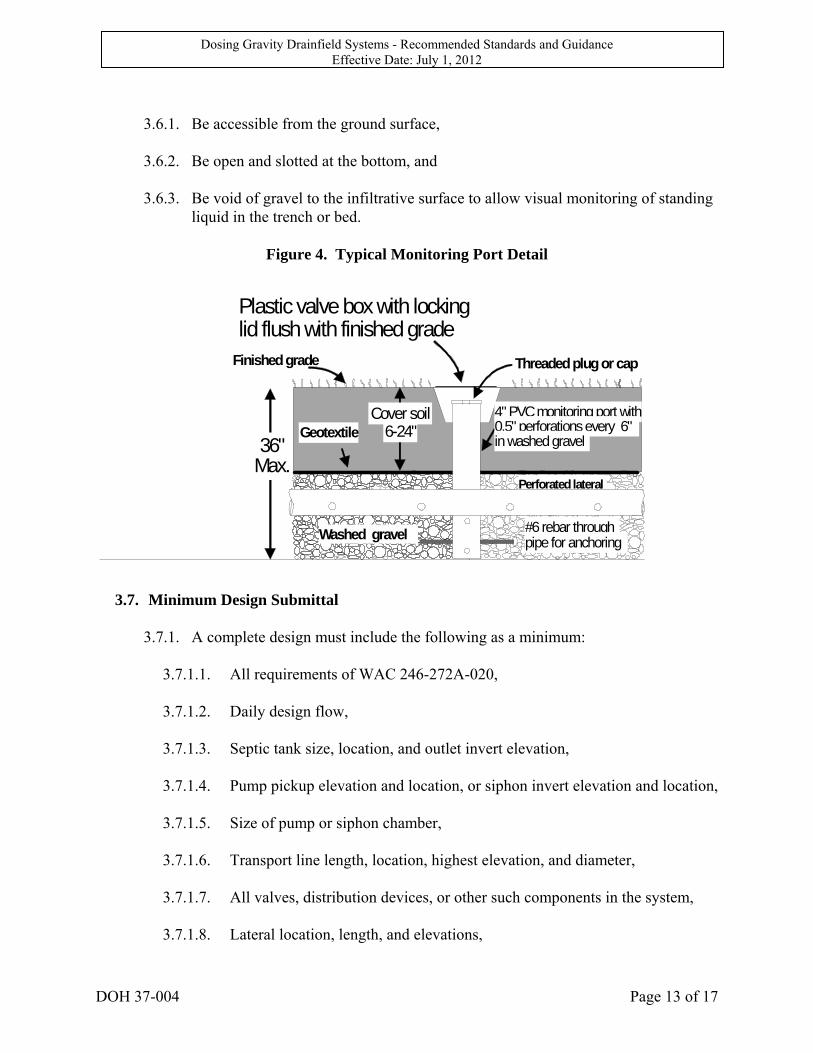
3.6. Monitoring Ports - All dosing systems must be equipped with a monitoring port in a
representative location on each drainfield line. Some drainfield lines may require additional monitoring ports to achieve observations representative of the entire drainfield line. (See Figure 4). These ports must:
Dosing Gravity Drainfield Systems - Recommended Standards and Guidance Effective Date: July 1, 2012
DOH 37-004 Page 13 of 17
3.6.1. Be accessible from the ground surface,
3.6.2. Be open and slotted at the bottom, and
3.6.3. Be void of gravel to the infiltrative surface to allow visual monitoring of standing
liquid in the trench or bed.
Figure 4. Typical Monitoring Port Detail
3.7. Minimum Design Submittal
3.7.1. A complete design must include the following as a minimum:
3.7.1.1. All requirements of WAC 246-272A-020, 3.7.1.2. Daily design flow, 3.7.1.3. Septic tank size, location, and outlet invert elevation, 3.7.1.4. Pump pickup elevation and location, or siphon invert elevation and location, 3.7.1.5. Size of pump or siphon chamber, 3.7.1.6. Transport line length, location, highest elevation, and diameter, 3.7.1.7. All valves, distribution devices, or other such components in the system, 3.7.1.8. Lateral location, length, and elevations,
36" Max.
Geotextile
Perforated lateral
Threaded plug or cap
Plastic valve box with locking lid flush with finished grade
Finished grade
Cover soil6-24"
4" PVC monitoring port with 0.5" perforations every 6" in washed gravel
#6 rebar through pipe for anchoring Washed gravel
Dosing Gravity Drainfield Systems - Recommended Standards and Guidance Effective Date: July 1, 2012
DOH 37-004 Page 14 of 17
3.7.1.9. Dose volume, pumping rate (GPM), dose frequency, and total system
design head, 3.7.1.10. Location and detail of monitoring ports in the trenches or beds, 3.7.1.11. Detail of pump controls, floats, and the position of floats, 3.7.1.12. An electrical wiring diagram specific to the project, 3.7.1.13. System parameters and calculations used by the designer to arrive at the
component sizing and flow distribution shown in the design, and 3.7.1.14. A user manual for the dosing system must be developed and provided to the
homeowner and the local health jurisdiction. See section 3.11 for a list of items to be included in the manual.
3.8. Minimum Record Drawing Information - A completed record drawing submission
must contain, at a minimum, the following items:
3.8.1. All the items contained in the design submittal listed above, as installed, identifying any changes from the approved plan,
3.8.2. The measured drawdown per dose cycle, 3.8.3. Timer functions, if a timer is installed, and 3.8.4. Pump run time and pump time off.
4. Operation and Maintenance Standards
4.1. Dosing systems must be monitored and maintained at a frequency commensurate with the site, soil, system complexity, and use patterns. As a minimum, the items in 4.2 - 4.7 must be inspected at six months and then yearly, after the system is put into use. The local health department must require that the permit clearly delineate who must perform the inspections. Refer to the system record drawing or as-built for initial readings and settings. The owners of dosing systems must be notified that their system must be inspected and serviced on a yearly basis. All findings and repairs are to be recorded, records filed for ready access and reports sent to local health department.
4.2. User’s Manual - The user’s manual that is a part of the design submittal must contain,
at a minimum, the following:
4.2.1. Diagrams of the system components, 4.2.2. Explanation of system function, operation expectations, owner responsibility, etc,
Dosing Gravity Drainfield Systems - Recommended Standards and Guidance Effective Date: July 1, 2012
DOH 37-004 Page 15 of 17
4.2.3. Specifications of all electrical and mechanical components installed (occasionally
components other than those specified on the plans is used), 4.2.4. Names and telephone numbers of the system designer, local health authority,
component manufacturer, supplier/installer, and/or the management entity to be contacted in the event of a failure,
4.2.5. Information on the periodic maintenance requirements of the various components
of the sewage system, and 4.2.6. Information on “trouble-shooting” common operational problems that might occur.
This information should be as detailed and complete as needed to assist the system owner to make accurate decisions about when and how to attempt corrections of operational problems, and when to call for professional assistance.
4.3. Evaluate Septic Tank And Pump Chamber
4.3.1. Sludge and scum accumulations; pump as necessary. 4.3.2. Clogging, damage, and proper placement of outlet baffle screen. Clean the screen
each time it is inspected or as needed to avoid clogging. 4.3.3. Signs of leaking in tanks and risers. Repair or replace if necessary. 4.3.4. Risers and lids being at or above grade and having lids secure from unauthorized
entry. 4.3.5. Properly functioning of floats. Movement should not be restricted. Floats should
be positioned correctly and provide positive instrumentation signals. Adjust and repair as necessary.
4.3.6. Measure pump run time per cycle and drawdown. Compare with time recorded in
record drawing or as-built. 4.3.7. Test alarms for proper functioning (high and low liquid level).
4.4. Evaluate Drainfield Area
4.4.1. Indication of surfacing effluent. 4.4.2. Appropriate vegetation. 4.4.3. Absence of heavy traffic. 4.4.4. Inappropriate building.
Dosing Gravity Drainfield Systems - Recommended Standards and Guidance Effective Date: July 1, 2012
DOH 37-004 Page 16 of 17
4.4.5. Impervious materials or surfaces. 4.4.6. Abnormal settling or erosion. 4.4.7. Evaluate monitoring ports for evidence of ponding. Check depth of ponding.
4.5. Distribution Devices
4.5.1. Evaluate D-Box for:
4.5.1.1. Uneven settling of D-box. 4.5.1.2. Levelness of inverts of outlets of D-box. 4.5.1.3. Uniformity of outlet flow of D-box. 4.5.1.4. Depth of effluent in the D-box. 4.5.1.5. Solids accumulations in the D-box.
4.5.2. Evaluate distributing value for proper rotation of the valve through the clear
sections of outlet pipe.

Dosing Gravity Drainfield Systems - Recommended Standards and Guidance Effective Date: July 1, 2012
DOH 37-004 Page 17 of 17
Appendix A Standard Specification for Geotextile in Subsurface Soil Absorption Systems (SSAS) The geotextile shall be of non-woven, and meet or exceed the following "Minimum Average Roll Values." The fabric shall be free of any chemical treatment or coating which reduces permeability and shall be inert to chemicals commonly found in soil.
Table 3. Geotextile Specifications
Property Test Procedure Unit Minimum Value
Grab Strength ASTM D4632 Lbs. 60
Puncture Tear ASTM D4833 Lbs. 18
Trapezoid Tear ASTM D4533 Lbs. 25
Apparent Opening Size (AOS) ASTM D4751 U.S. Std. Sieve (1)
Flow Rate ASTM D4491 gal/ft2/min 100
(1) Soil with 50% or less particles by weight passing US No. 200 sieve, AOS less than 0.6 mm (greater than #30 US
Std. Sieve). Soil with more than 50% particles by weight passing US No. 200 Sieve, AOS less than 0.297 mm (greater
than #50 US Std. Sieve).