Embed Size (px)
Citation preview
DASA- 1703USNRDL-TR-9393 December 1965
, DOSE RATE AND SPECTRAL MEASUREMENTS FROM PULSEDX-RAY GENERATORS
:j byE. TochilinN. Goldstein
C L E A R 1 f4 G 11 0 U S EFOR FEDrRAL SCiETNTIFIC AND
TECHNICAL INFORMITATIONHardcop " M icrofiehe j
U.S. NAVAL RADIOLOGICALDEFENSE LABORATORY
S A N FRANCISCO -CALIFORNIA- 94135
RADIOLOGICAL PHYSICS BRANCHE. Tochilin, Head
NUCLEONICS DIVISIONC. S. Cook, Head
z
ADMINISTRATIVE INFORMATION
This report covers a portion of the work This document has been
authorized by the Defense Atomic Support Agency, approved for open pub-
4 NWETB-2, Subtask 06.518T. lication by the Depart-ment of Defense.
ACKNOWLEDGMENTS
The authors are indebted to many people with-out whose help this investigation could not have
been conducted, We wish to thank Mr. W. A. S.Lamb and the staff of the ASTRON facility for con-tributing their time. We are indebted to Mr.D. F. Martin of Physics International Co. formaking time available on the 1 Mv and 3 Mv flashX-ray units. We thank Mr. P. Caldwell of theHarry Diamond Laboratories for providing andreading the CaF2 dosimeters. Mr. F. G. Watsonassisted in the measurements taken at the 2 MeVVan de Graaff accelerator.
DDC AVAILABILITY NOTICE
Distribution of this document is unlimited.
Ii O Eugene P.Cooper D.C. Compbell, CAPT USNScientific Director Commanding Officer and Direclor
ABSTIRACT
Typical X-ray spectra from high intensity pulsed X-ray sources
were determined by means of an equivalent constant voltage accelerator.
Ihe photon energy spectri=n for the forward X-ray beam was measured with
various X-ray target thicknesses at accelerator voltages of 1.0, 1.5
and 2.0 Mv. X-ray spectra were also obtained from a reflection X-ray
target at angles of 7 deg and 45 deg with respect to the X-ray- beam
at applied potentials of 0.55, 1.0 and 2.0 Mv. The dose rate dependenceof.' thermo1noinescent LiF, silver-activated phosphate glass, and
dosimetry film was investigated over a range of dose rates extending
from 104 to 10l1 rad/sec with three separate flash X-ray systems.
SUNMARY
The Problem
The purpose of this experiment was to provide methods for
determining the spectrum and dose rates from pulsed X-ray generators
and to evaluate the dose rate response of various dosimeters at these
high intensities.
The Findings
X-ray spectra from 0.60, 1.0 and 2.0 Mv pulsed X-ray sources
were simulated by measurements made on the Laboratory Van de Graaff.
Transmission curves obtained at the Van de Graaff and flash X-ray
tr=its were used to establish an identity between the steady state
and pulsed X-ray spectra. No dose rate dependence was observed for
LiF and CaF2 thermoluminescent dosimeters and silver-activated phosphate
glass up to 10 1 rad/sec. DuPont 834 film exhibited a dose rate
drpendence above 5 x 10⁸ rad/sec ,.hich corresponds to a delivered dose
of 10 rad per pulse.
ii
INTRODUCTION
The past few years have seen the development of high-current pulsed
X-ray sources capable of producing instantaneous dose rates exceeding
10 1 rad/sec with maximum energies extending to 4 MeV.(1 -4 ) By utilizing
the electron beam from the higher energy units it is possible to
irradiate limited volumes of material with dose rates extending beyond
1012 rad/sec. With the electrcn beam, doses approaching 100,000 rads
per pulse become entirely feasible. ( 4 )
One major problem confronting the experimenter is how to make
meaningful dosimetric measurements under such conditions. Another
problem arising from the use of pulsed X-rays involves the determination
of their spectral distribution. In order to achieve maximum X-ray
intensity, reflection targets or thin transmission targets are used
which results in a significant low-energy component. Since many
dosimetry systeimused in pulsed beam dosimetry exhibit energy dependence
in this energy region, e.g., glass dosimeters and photographic emulsions,
it becomes important to establish their energy response for any such
exposure condition.
One method of obtaining spectral information on pulsed X-ray beams
is to design an identical tube assembly and adapt it to a conventional
1
~kI
electron accelerator. This will produce a steady state version of the
pulsed source whose X-ray spectrum can then be analyzed by means of a
NaI(Tl) scintillation spectrometer. Many additional beam parameters
can be investigated with a properly designed tube assembly--optimum
target thickness (transmitted beam) or optimum target angle (reflected
beam) for maximum output; changes in beam intensity and spectral
distribution due to external absorbers; beam distribution and inverse
square relationship at distances close to the target; etc.
Special target assemblies adapted to a 2 MeV Van de Graaff
accelerator allowed spectral measurements to be made in the energy
range from 0.5 to 2 MeV for both transmission and reflection targets.
From this information the physical properties of a pulsed 6oo kv X-ray
machine (-ith reflection target) and a pulsed 1 Mv source (with
transmission target) were determined, following which the ener&T and
dose rate response of various dosimetry systems were investigated.
Four pulsed sources were made available for this study. These
included: a 600 kv X-ray system; ( 1 ) two X-ray systems (1 and 3 Mv)*
developed for simuiation studies; (2) and the Mtron pulsed 4 MeV
electron accelerator at the University of California Lawrence Radiation
Laboratory. ( 3 ) When completed the Astron unit will be used as an
* The 1 and 3 Mv X-ray systems were made available for dose rate
measurements by the Physics International Company, San Leandro,
California.
2
experimental thermonuclear power reactcr with the pulsed electrons
used to confine the plasma and supply the energy required to attain
-* fusion temperatures. ( 3 ) For the present study the electrons were
stopped in a water-cooled tantalum target attached to the end of the
accelerator tube.
STEADY STATE X-RAY MEASUREMEN
A 2 MeV Van de Graaff electron accelerator was used to provide
a steady state equivalent of the 600 kv and 1 Mv flash X-ray units.
A target assembly was designed to hold water-cooled tungsten targets
at the desired angles to the electron beam. With this arrangement the
spectral distribution and intensity of X-rays reflected from the target
could be studied for various target angles. 2he target housing had a
0.15 mm Be window to allow transmission of low-energy X-rays. Measure-
ments were also made with transmission targets in wiich the target
material was placed at the end of the accelerator tube in a plane
normal to the beam axis.
X-ray spectra were determined by analysis of pulse height spectra
from a 10 cm diameter by 10 cm long NaI(Tl) cry3tal optically coupled
to a 12.5 cm diameter photomultiplier tube. She amplified signals from
the photomltiplier tube were counted in an hundred-channel analyzer.
The X-rays entered the shielded crystal through a lead collimator plug
23 cm long with a 1.27 cm aperture. Reduction of pulse height
3
distribution to X-ray spectrum followed calculation techniques developed
in an earlier investigation. ( 5 ) Dose rate measurements were made with
a Victoreen thick-wall 25 R thimble chamber calibrated by the Bureau of
Standards against Co 6 o gscma rays. Subsequent checks were made with a
Cs1 3 7 standard source (0.66 MeV gamna rays) and with a 250 kv X-ray
source for effective X-ray energies ranging from 40 to 155 keV. A
calibrated low-energy 25 R thimble chamber served as the X-ray compari-
son standard.
X-RAY SPEOTRA
600 kv pulsed X-ray unit
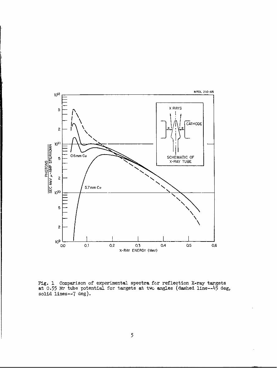
The 6oo kv flash X-ray tube is designed primarily for flash
radiography.(') 'The cathode consists of a thin cylinder which
surrounds a thick conical tungsten anode. Electrons from the cathode
impinge on the anode and emit X-rays through a glass window in the
direction of the target axis. The conical anode target makes an angle
of 7 deg with its central axis (Fig. 1). In order to prolong tube
life the unit was operated at 550 kv.
Spectral measurements were made on the Van de Graaff accelerator
with the electron beam projected vertically downward and a flat
tungsten target positioned at the 7 deg angle. The NaT crystal and Pb
collimator were placed in a horizontal position facing the tungsten
target. Measurements of the reflected X-ray spectrum for 550 keV
4
NRDL. 210-651012
5 X RAYS
!eTHODE
Z 101,
00-
MI
>L 2
5
109 .0.0 0.1 020.3 0.4 0.5 0.6
X-RAY ENERGY (Me-I)
Fig. 1. Comparison of experimental spectra fo~r reflection X-ray targetsat 0.55 IM'.' tube potential for targets at two angles (dashed line--45 deg,solid lines--7 deg).
5
electrons were made with the beam passing through the 0.15 mm Be filter
and with additional filters of 0.6 mm and 5.7 mm. of Cu. In addition
the beam traversed 2.2 m of air and 0.25 mm of Al covering the Nal
crystal. The resultant spectra are shown as solid curves in Fig. 1
while the dashed curve is the spectrum for a 45 deg reflection target.
The unfiltered beam is a typical continuous X-ray spectrum rising to a
broad maximu= around 100-130 keV. Accompanying the continuous
distribution is the characteristic radiation for tungsten photons at
around 60 keV arising from the transition of excited atoms to lower
energy levels. The 0.6 m Cu filter selectively reduces the intensity
at the expense of lower energies and shifts the population maximum of
the continuous spectrum to a higher energy. With a 5.7 Mn Cu filter
the 60 keV tungsten line is almost completely eliminated while the dose
rate is reduced by a factor of two. Additional curves comparing the
spectral response of reflection tungsten targets positioned at 7 deg
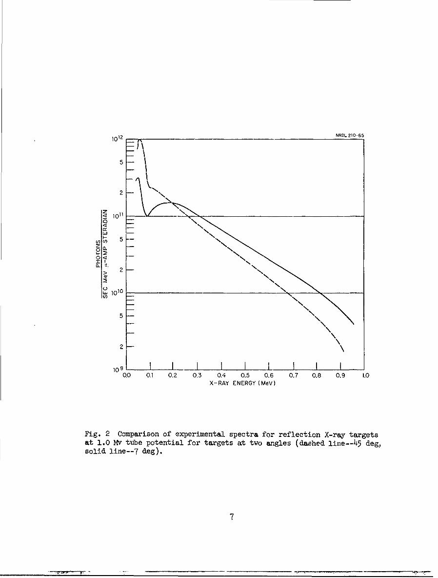
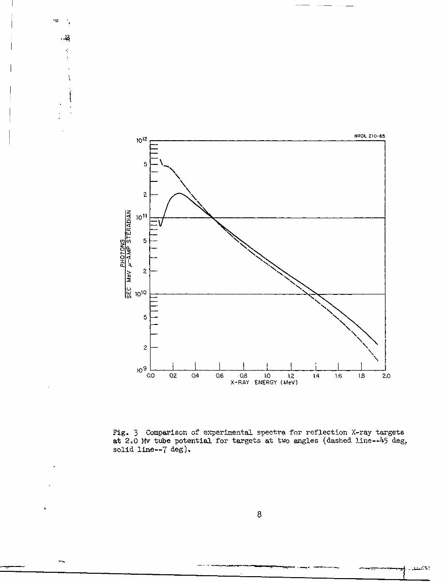
and 45 deg for 1 and 2 MeV electrons are presented in Figs. 2 and 3.
Another method of determining spectral distribution is the
attenuation method described by Greening (6) which is based on the
analysis or attenuation curves. A modified version of this technique
wvs used by Bouchard ( 7 ) to estimate the energy spectrum from a similar
600 kv flash X-ray system. Using film as a detector, absorption curves
with different filter materials were obtained. The measured optical
densities were then compared vith expected values from an initially
6
1012 _ NROL 210-65
2
1011
wW M
Z. a
2
INw 1010 N,
5
2
1 I0I I I I L LI I L0.0 0.1 0.2 0.3 0.4 0.5 0.6 0.7 0.8 0.9 1.0
X-RAY ENERGY (MeV)
Fig. 2 Comparison of experimental spectra for reflection X-ray targetsat 1.0 Mv tube potential for targets at two angles (dashed line--45 deg,solid line--7 deg).
7
I
1012 NROL 210-65
< 1011
m 5
> 2 N Nx\\\\\4)
1010
5\
> 2
1 0 ~ ~ i L L Lf0.0 0.2 0.4 0.6 0.8 1.0 1.2 1.4 1.6 1.8 2.0
X-RAY ENERGY (MeV)
Fig. 3 Comparison of e:perm-enta. spectra for reflection X-ray targetsat 2.0 Mv tube potential for targets at two angles (dashed line--45 deg,solid line--7 deg).
8
assumed photon energy spectrum. The proposed spectrum was then
successively modified in such a manner that the spread in experimental
and calculated results was reduced to less than 10 percemt. The
resultant spectrum, with a 1.6 mm Cu filter, showed a broad maximum
between 200-300 keV which is in contradiction with our present
measurements. It is of interest to note that the first approximation
spectrum for Bouchard's analysis, a calculated continuous spectrum
based on Kramers' formula (8) was quite similar to our measured
distribution with the 5.7 m Cu filter.
The attenuation method was used in our measurements to establish
an identity between the steady state and pulsed X-ray spectrum. Copper
transmission curves obtained at the Van de Graaff and at the flash
X-ray unit were found to be identical for thickness greater than o.6 mm.
A combination of measurements with ionization chambers and thermo-
luminescent iAF dosimeters were used to obtain data for the pulsed
beam. Ionizatian chambers were used only at dose rates where
recombination effects were not significant. A more rapid attenuation
of the pulsed beam was observed over the initial portion of the
transmission curve which indicated the presence of low-energy electrons
in addition to the 550 keV component. This condition was oosrved for
three separate tubes. One possible explanation is that the tube was
raot holding its original vacuum and was therefore "gassy." For this
reason it may be preferable to operate with enough filtration to
9
eliminate any undesirable soft X-ray component not directly attributable
to the primary electron Ileum.
One Mv pulsed X-ray unit
The 1 Mv pulsed X-ray tube used a transmission tungsten target
backed by 6.4 mm of aluminum with the plane of the target normal to the
electron beam. The tube could be readily dismantled which allowed a
variation in thickness of target material.
An experiment with 1 MeV electrons was conducted with the
Van de Graaff to determine the effect of target thickness on X-ray
spectrum and dose rate. Measurements were made with tungsten target
thicknesses varied from 0.127 to 0.508 mm with and without backing of
1 cm of aluminum and also with additional copper filters 0.56 and 1.88
=m thick. The Al backing had little effect on the measured spectrum
other than to reduce the intensity by approximately 20 percent over
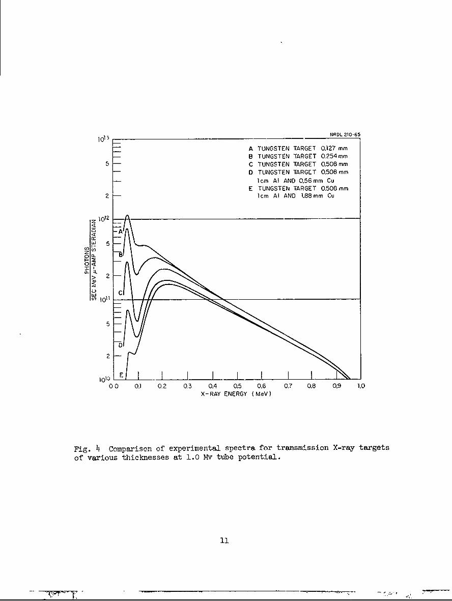
all energies. Figure 4 shows spectra obtained with target thicknesses
of 0.127, 0.254, and 0.508 mm. The lower two curvas in Fig. 4 show
the effect of additional copper filters. Characteristics X-rays for
tungsten are seen to exist even for a thick target (0.508 mm of
tungsten) but may be eliminatedl by adding a copper absorber. Figures
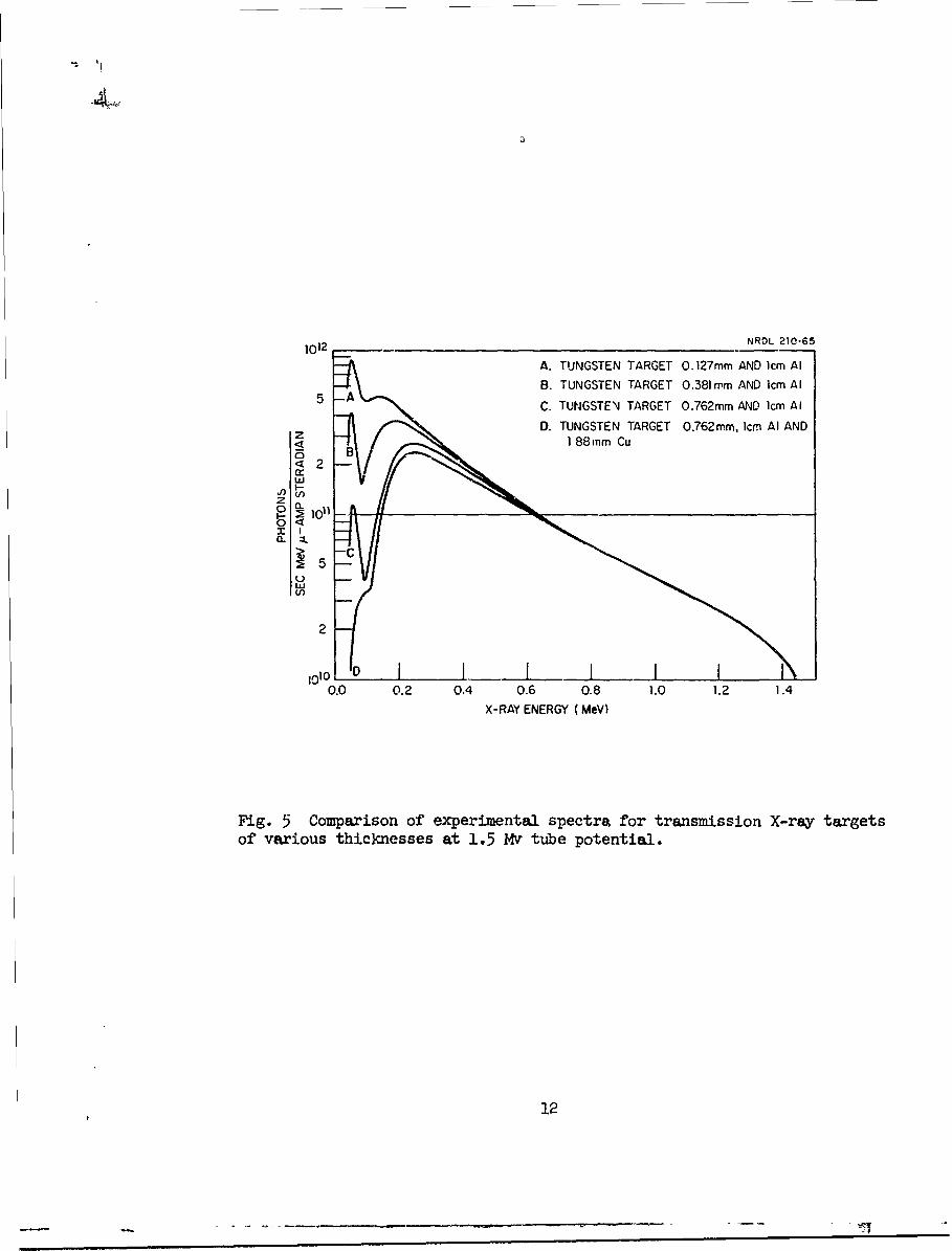
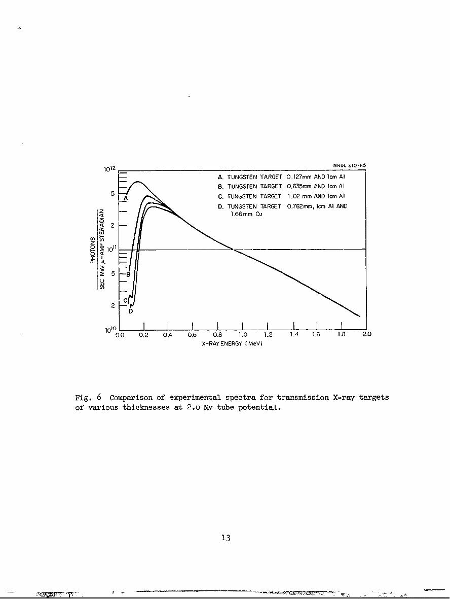
5 and 6 show similar spectra obtained with transmission tungsten
targets of various thicknesses for 1.5 and 2 Mv tube potential.
Characteristic X-rays from the tungsten target were not resolved
for the 2 Mv spectra of Fig. 6 as was the case at lower energies.
10
NRDL 210-65
A0 TUGSE TARGET 0.127 min__
A TUNGSTEN TARGET 0.127 mm5 B TUNGSTEN TARGET 0.54 mm5D TUNGSTEN TARGET 0.508 mm
1cm Al AND 0.56 mm CuE TUNGSTEN TARGET 0.508mm
2 1cm Al AND 1.88 mm Cu
5
X-A ENRY)MV
5- iti
1012 NROL 210-65
A. TUNGSTEN TARGET 0.127mm AND 1cm Al
B. TUNGSTEN TARGET 0.381 mm AND 1cm AlAC. TUNGSTEN TARGET 0.762mm AND 1cm Al
D. TUNGSTEN TARGET 0.762mm, cm Al AND
S_ ]188 ram Cu
o~
0 B
2
z C
M 1010
Vf)
0.0 0.2 0.4 0.6 0.8 1.0 1.2 1.4X-RAY ENERGY (MeV)
Fig. 5 Comparison of experimental spectra for transmission X-ray targetsof various thicknesses at 1.5 Mv tube potential.
12
1012 NROL 210-65
A. TUNGSTEN TARGET 0.127mm AND 1cm Al
B, TUNGSTEN TARGET 0.635rnm AND 1cm Al5 A C. TUNbSTEN TARGET 1.02 mm AND 1cm Al
D. TUNGSTEN TARGET 0.762rm, 1cm Al AND_ 1.66mm Cu
101° I I I I I I I I .....................0.0 0.2 0.4 0.6 0.8 1.0 1.2 1.4 1.6 1.8 2.0
X-RA< ENERGY (Me)
Fig. 6 Comparison of experimental spectra for transmission X-ray targets
of various thicknesses at 2.0 Mv tube potential.
13
-0-
The magnitude of this component may be estimated by reference to
Edelsack, et al., where X-ray spectra from thick gold targets were
determined for electrons of 1.0, 1.5, and 2.0 MeV. ( 5 )
Doses associated with the measured spectra were foxud to decrease
exponentially with increasing target thickness. From an inspection of
Fig. 4 one sees that the 0.508 rm tungsten target eliminates a large
component of low-energy X-rays originally transmitted through 0.127 mm
of tungsten. The overall spectral attenuation corzesponded to a 25
percent decrease in dose rate. The additional 1.88 mm of copper 'which
essentially eliminates the 60 keV tungsten line produces an additional
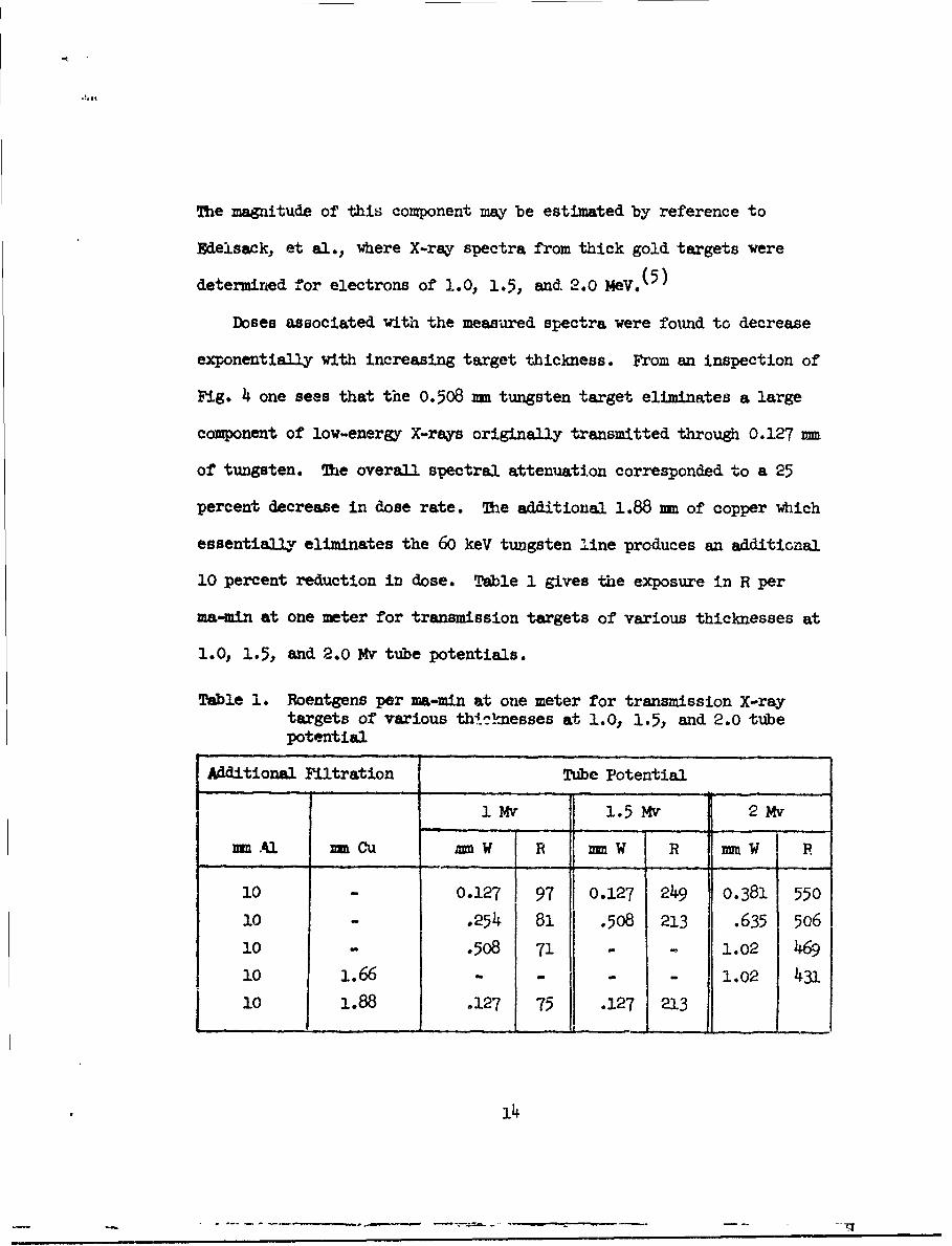
10 percent reduction in dose. Table 1 gives the exposure in R per
ma-mmn at one meter for transmission targets of various thicknesses at
1.0, 1.5, and 2.0 Mv tube potentials.
Table 1. Roentgens per ma-min at one meter for transmission X-raytargets of various th'Lnmesses at 1.0, 1.5, and 2.0 tubepotential
Additional Filtration Tube Potential
1Mv 1.5Mv 2Mv
mm Al mmCu MMW R mmW R UMW F
10 - 0.127 97 0.127 249 0.381 550
10 .254 81 .508 213 .635 506
10 - .508 71 - - 1.02 469
10 1.66 - - - - 1.02 431
i 0 1.88 .127 75 .127 213
14
DOSE RATE STJDIES
Ihe dose rate response of silver-activated phosphate glass,
thermoluminescent LiF?* and dosimeter film were initially studied with
pulsed X-rays from the Astron accelerator. Under normal operation the
Astron been was pulsed five times a second. This time interval was
sufficiently long so that the dose from each pulse was completely
resolved by each dosimeter system prior to the arrival of the next
burst of X-rays. At the higher dose rates a small number of runs were
also made with single pulses.
Beam current was monitored by taking a photograph of an oscillo-
scope trace from a single pulse made at the end of each run. Integra-
ting the pulse area gave the charge which averaged 20 Wcoulombs per
pulse delivered over a period slightly greater than 0.35 psec. The
pulse shape was rectangular over the first 0.1 psec after which it
decreased linearly to zero. The average pulse time was assumed to be
0.3 psec during this exposure period.
* These included the high-Z and low-Z fluorod glasses manufactured by
Bausch and Lmb, Inc., Rochester, New York, and the low-Z fluorods
and glass plates manufactured by Tokyo Shibaura Electric Co., Ltd.,
Tokyo.
** Manufactured by the Harshaw Chemical Co., Cleveland, Ohio.
15
The horizontal accelerator tube was about 3 m above the floor
and at least 5 m from the nearest wall in a large concrete building.
In order to minimize scattered radi-tion for auxiliary equipment in
the area the X-ray target was surrounded by a 5 cm thick lead housing.
A 5 cm diaeter aperture placed directly in line with the horizontal
electron beam and 20 cm ahead of the Ta target restricted the trans-
mitted X-ray beam to a 14 deg cone. The X-ray dose rate was determined
with a microcalorimeter positioned on the beam axis 188 cm from the
target. The microcalorimeter has been described in a separate
report. ( 9 ) Absorbed dose was determined over a series of seven 1-min
runs. The dose rate thus obtained was 54.6 carbon rad/min or 62 R/min
at an average current of 100 panps (100 pcoulombs/sec). For an average
current of 1 panp the output at 1 meter would be 2.2 R/min which is in
agreement with other data in the literature. (10)
Dose rate measurements were monitored with Sievert type ionization
chobers.*( I I ) They were ahosen because of the small separation
between central cathode and outer wall which is necessary in order to
attain sufficient field strength to achieve saturation at high dose
rates. The chambers are cylindrical in shape, ubout 5 = in diameter
and 2 cm long. With a charger-x'eader designed to apply a 600 v
potential to the chambers a full scale reading of about 250 rad was
* Manufactured by Alderson Research Laboratories, lng Islard City,
New York.
16
obtained. A second 150 v charger-reader gave a full scale reading
of 50 rad.
Having determined the X-ray output at one point the dosixeters
were then calibrated at this distance. Dose rate dependence of the
various systems was studied by assuming an inverse square relationship
over the distance between 10-40W cm and observing how well the
individual dosimeter response followed this predicted relationship.
An additional check on output was provided by the Sievert ionization
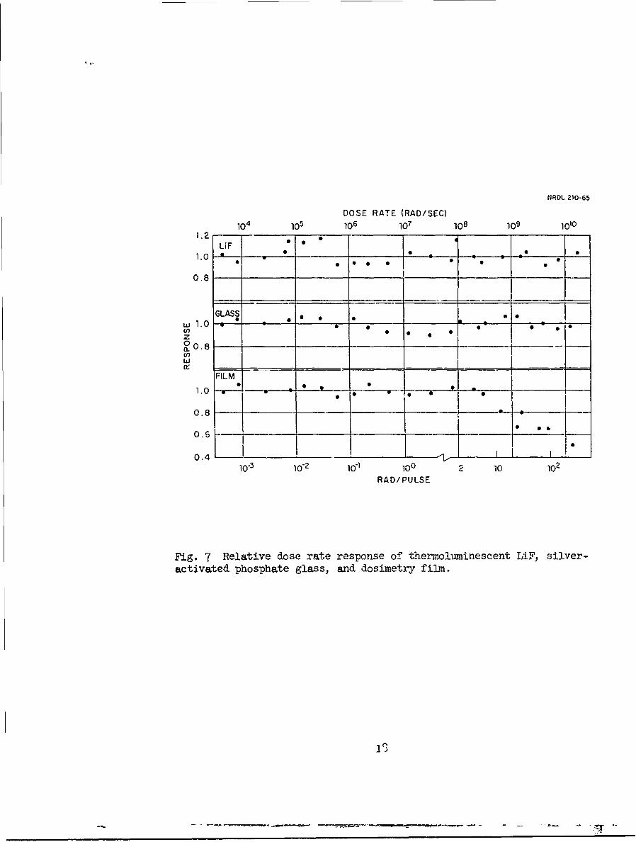
chambers. Figure 7 shows the dose rate response of silver-activated
phosphate glass, photographic emulsion (DuPont types 555 and 834) and
thermoluminescent LiF over dose rates extending from 5 x 10 to
2 x 10⁷ rad/sec. Over this range the three dosimetry systems are
essentially independent of dose rate.
The accuracy of these measurements was difficult to assess but
probably was within ' 10 percent for all exposures. Each run consisted
of dosimeters placed at two distances with the front group of dosimeters
positioned so as not to shield the ones further back. Al runs were at
a constant beam current; the total dose received for each run being
determined by exposure time. For dose rates below 10 rad/sec beam
intensity was reduced by means of a 2-in. thick Pb absorber.
Normalization was achieved from the average reading of five Sievert
ionization chambers which were exposed at each point. Two LiP and
glass dosimeters and one film dosimeter were exposed along with the
Sievert chambers.
17
NROL 210-65
DOSE RATE (RAD/SEC)
104 105 106 107 108 109 1010
LiF I1. 0 -
0.8
GLASS * * *
z . 0 * *• 0
uj . 0
w
FILM
0.8 1--0 .6
0 .4 ,0_ - 1 . ,
10-3 iO"2 10"1 100 2 10 102
RAD/PULSE
Fig. 7 Relative dose rate response of thermoluminescent LiF, silver-activated phosphate glassj and dosimetry film.
Dose rate studies for the silver-activated phosphate glass and
thermoluminescent LiF dosimeters were extended to the 1 My pulsed
X-ray source where dose rates of 1.7 x 10¹⁰ rad/sec were obtained
2.75 cm from the target. A dose of 350 rad per pulse was delivered at
this dose rate. Once again measurements were made using inverse square
to obtain dose rates from 108 to 1.7 x 10¹⁰ rad/sec over the distance
between 2.7 and 24 cm. The results are shown also in Fig. 7 and
indicate no dose rate dependence for the glass and LiF dosimeters.
previous measurements by Karzmark, et al., with the LiF dosimeter
showed no dose rate dependence from 5 x 10² to 2 x 10⁸ rad/sec.(1 2)
On the other hand a dose rate effect is clearly indicated for DuPont
type 834 dosimeter film for dose rates in excess of 5 x 10⁸ red/sec
which corresponds to a delivered dose of 10 rd per pulse.
Using somewhat modified exposure conditions at the 3 My pulsed
X-ray source it was possible to extend measurements with LiF and
glass to dose rates over 2 x 1on rad'sec (1450 rad/pulse) with no
indication of dose rate effects (within ± 10 percent). CaF2 thermo-
luminescent dosimeters exposed. under the same conditions also showed
no dose rate effects up to l0 l rad/sec.*
* The CaF2 dosimeters were furnished for exposure and read by Harry
Diamond Laboratories personnel, U.S. Army Materiel Command., Washington,
D.C. They were manufactured by Edgerton, Germeshausen and Grier, Inc.,
Santa Barbara, California.
19
A further check on the dose rate from the 3 Mr pulsed X-ray
machine was made with a microcalorimeter positioned 10 cm from the
target.(13) The average dose for a pulse of 2 x 10- 8 sec was about
500 R. Simultaneous measurements made with the microcalorimeter and
Li dosimeters gave the same value within an experimental error of
5 percent. 7he independent intercomparison further established the
lack of dose rate effects for the systems under study.
Mhe behavior of integrating ionization chambers exposed to either
high intensity continuous radiation or to instantaneous pulses of
radiation may be determined from generalized saturation curves developed
by Boag.(4) Instantaneous pulses are those whose duration is short
compared with the time required for complete ion collection in the
chamber, which is the order of milliseconds. Because solid state
dosimeters of the type described have such excellent response
characteristics to pulsed radiation it becomes a routine matter to
construct a response curve for any ionization chamber. However, in
some instances it =W be desirable to fit a single point to the
saturation curves presented by Boag and thereby obviate the need for
additional measurements. The dose rate response as predicted from
Boag's data has generally been found to be greater than that obtained
experimentally. 7he difference can be accounted for if the empirical
constant m given by Boag as 15.9 is increased to an average value of
36.7 as deterwmned by Greening by analysis of the experimental results
20
of seven different workers.(l5) It is of interest to note that the
value of m obtained by Greening in reviewing the original experimental
data of Boag was at variance with his published value but in good
agreement with the average number.
21
REFRENCES
1. F. J. Grundhauser, W. P. Dyke and S. D. Bennett, "A Fifty-
Millimicrosecond Flash X-Ray System for High Speed Radiographs,"
J SMPTE 70:435, 1961.
2. F. C. Ford, et al., "A One-MeV Pulsed X-Ray Facility for Simulation
Work," Joint ANS-ASH4 Conference, American Nuclear Society Radiation
Effects in Electronics, Syracuse, New York, Physics International
Company PIPB-5, 1964.
3. N. C. Christofilos, et al., "High Current Linear Induction
Accelerator for Electrons," RS1I 35:886, 1964.
. FEBETRON--A High Intensity Pulsed Source of Electrons and X-Rays,
Field Emission Corporation Technical Bulletin 4. No. 1, April 1965.
5. E. A. Edelsack, et al., "Experimental Investigation of Mhick Target
Bremsstrahlung Radiation Produced by Electrons of 1.00, 1.50 and
2.00 MeV," Health Physics 4:1, 1960.
6. J. R. Greening, "The Determination of X-Ray Wavelength Distributions
from Absorption Data," Proc. Phys. Soc. 63A:1227, 1950.
7. G. H. Bouchard, "Measurement of Bremsstrahlung Dose and Spectrum
from a 600 kvp Pulsed X-Ray Generator Using Photographic Film,"
Sandia Corporation TID-16041, 1962.
8. H. A. Kramers, "On the Theory of X-Ray Absorption and of the
Continuous X-Ray Spectrum," Phil. Mag. 46:836, 1923.
22
REFEC (contd.)
9. E. R. Schleiger, N. Goldstein and E. Tochilin, "Calorimetric
Measurements of Gema-Ray, Fast Neutron and Charged Particle
Doses," USNRDL-TR-621, January 1963.
10. J. H. Bly and E. A. Burrill, "High Energy Radiography in the 6 to
30 MeV Range," Symposium on Nondestructive Testing in the Missile
Industry. AST4 Special Technical Publication No. 278, pp. 20-39,
196o.
11. H. Skoldborn, "On the Design, Physical Properties and Practical
Application of Small Condenser Ionization Chambers," Acta Radiol.
Suppl. 187, 1959.
12. C. J. Karzmark, J. White and J. F. Fowler, "Lithium Fluoride
Thermoluminescence Dosimetry," Phys. in Med. and Biol. 2:273, 1964.
13. E. R. Schleiger and N. Goldstein, "Prototype of a Portable
Microcalorimeter for Measurement of Absorbed Dose," R.S.I. 35:890,
1964.
14. J. W. Boag, "Ionization Chambers," in Radiation Dosimetry (G. J. Hine
and G. L. Brownell, eds. ), pp. 153-212, Academic Press, New York,
1956:
15. J. R. Greening, "Saturation Characteristics of Parallel-Plate
Ionization Chambers," Phys. in Med. and Biol. 9:143, 1964.
23
UNCLASSIFIEDSecurity Classification
DOCUMENT CONTROL DATA -R&D(Security cloaeIlcation of title, body of obstract end indexing annotatuon must be entered when the overall report is c /ess fted)
I ORIGINATING AC rIVITY (Corporate author) 2a RCPORI SECURITY C LASSIFICATION
U. S. Naval Radiological Defense Laboratory UNCLASSIFIEDSan Francisco, California 94135 2b GROUP
3 REPORT TITLE
DOSE RATE AND SPECTRAL MEASUREMENTS FROM PULSED X-RAY GENRATORS
4 DESCRIPTIVE NOES (Type of report and inclusive dete&)
S AUTHOR(S) (Last name, 1lrat name, initial)
Tochilin, EugeneGoldstein, Norman
6. REPORT DATE 78 TOTAL NO. OF PAGES 7b NO. OF REFS
8 February 1966 28 15as. CONTRACT OR GRANT NO. 9a. ORIGINATOR'S REPORT NUMSER(S)
b. PROJECT NO. DASA NWETB-2 USNRDL-TR-939
Subtask 06.518Tc 9b OTHER REPORT NO(S) (Any othernumbers that may be asaigned
this report)
d
10 AVA IL ABILITY/LIMITATION NOTCES
Distribution of this document is unlimited.
II SUPPLEMENTARY NOTES 12. SPONSORING MILITARY ACTIVITY
Defense Atomic Support AgencyWashiegton,D.C. 2030-
13 ABSTRACT
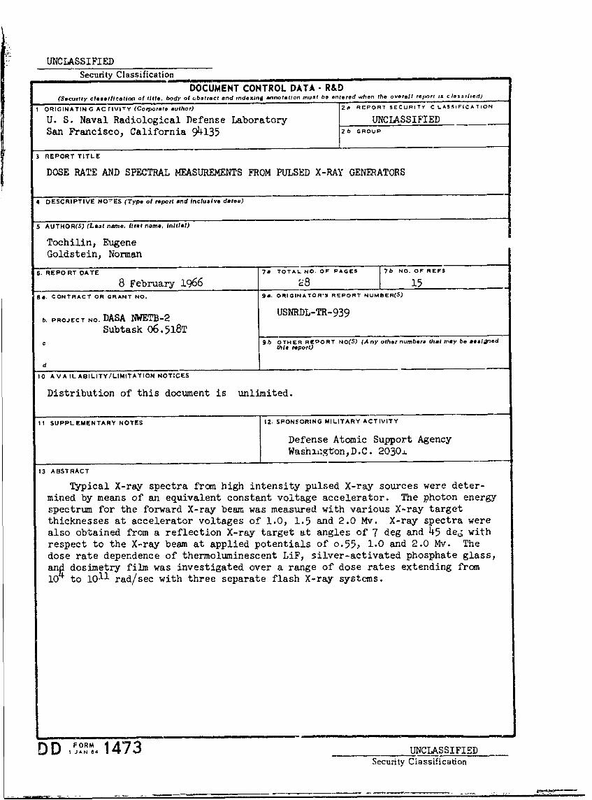
Typical X-ray spectra fro high intensity pulsed X-ray sources were deter-mined by means of an equivalent constant voltage accelerator. The photon energyspectrum for the forward X-ray beam was measured with various X-ray targetthicknesses at accelerator voltages of 1.0, 1.5 and 2.0 Mv. X-ray spectra werealso obtained from a reflection X-ray target at angles of 7 deg and 45 de. withrespect to the X-ray beam at applied potentials of o.55, 1.0 and 2.0 Mv. Thedose rate dependence of thermoluminescent LiF, silver-activated phosphate glass,an dosimetry film was investigated over a range of dose rates extending from10 to 1011 rad/sec with three separate flash X-ray systems.
I Iml
DD IJAN 8 1473 UNCLASSIFIEDSecu-ity Classification
UNCLASSIFIEDSecurity Classification
LINK A LINK 8 LINK CKEY WORDS ROLE W ROLF! WT ROLE WT
SpectraDosimetryX-raysThermoluminescencePhotoluminescenc e
IA
INSTRUCTIONS
I. ORIGINATING ACTIVITY: Enter the name and address imposed by security classification, using standard statementsof the contractor, subcontractor, grantee, Department of De- such as:fense activity or other organization (corporate author) issuing (1) "Qualified requesters may obtain copies of thisthe report. report from DDC."
2a. REPORT SECUITY CLASSIFICATION: Enter the over- (2) "Foreign announcement and dissemination of "hisall security classification of the report. Indicate whether report by DDC is not authorized.""Restricted Data" Is included. Marking is to be in accord-ance with appropriate security regulations. (3) "U. S. Government agencies may obtain copies of
this report directly from DDC. Other qualified DDC2b. GROUP: Automatic downgrading is specified in DoD Di- users shall request throughrective 5200. 10 and Armed Forces Industrial Manual. Enterthe group number. Also, when applicable, show that optional ""
markings have been used for Group 3 and Group 4 as author- (4) "U. S. military agencies may obtain copies of thisized. report directly from DDC. Other qualified users3. REPORT TITLE: Enter the complete report title in all shall request throughcapital letters. Titles in all cases should be unclassified.If a meaningful title cannot be selected without classifica-tion, show title classification in all capitals in parenthesis (5) "All distribution of this report is controlled. Qual-
immediately following the title. ified DDC users shall request through
4. DESCRIPTIVE NOTES: If appropriate, enter th type of • ,'
report, e.g., interim, progress, summary, annual, or final. If the report has been furnished to the Office of TechnicalGive the inclusive dates when a specific reporting period is Services, Department of Commerce, for sa!e to the public, indi-covered. cate this fact and enter the price, if known.
5. AUTHOR(S): Enter the name(s) of author(s) as shown on IL SUPPLEMENTARY NOTES: Use for additional explana-or in the report. Enter last name, first name, middle initial, tory notes.If military, show rank and branch of service. The name ofthe principal iathor is an absolute minimum requirement. 12. SPONSORING MILITARY ACTIVITY: Enter the name of
the departmental project office or laboratory sponsoring (pay-6. REPORT DATE. Enter the date of the report as day, ing for) the research and development. Include address.mont., year, or month, year. If more than one date appearson the eport, use date of publication. 13, ABSTRACT: Enter an abstract giving a brief and factual
summary of the document indicative of the report, even though
should follow normal pagination procedures, i.e., enter the it may also appear elsewhere in the body of the technical re-port. If additional space i3 required, a continuation sheet shall
number of pages containing information, be attached.
7b. NUMBER OF REFERENCES: Enter the total number of It is highly desirable that the abstract of classified reportsreferences cited in the report. be unclassified. Each paragraph of the abstract shall end with
Sa. CONTRACT OR GRANT NUMBER: If appropripte, enter an indication of the military security classification of the in-
the applicab!e number of ths. contract or grant under which formation it. the paragraph, represented as (Ts). (S), (C), or (U).
the report was written. There is no limitation on the length of the abstract. How-
8b, 8c, & 8d. PROJECT NUMBER: Enter the appropriate ever, the suggested length is from 150 to 225 words.military department i'.sntification, such as project number,subproject number, s3stern numbers, task number, etc. 14 KEY WORDS: Key words are technically meaningful terms
or short phrases that characterize a report and may be used as9a. ORIGINATOR'S REPORT NUMBER(S): Enter the offi- index entries fo- cataloging the report. Key words must becial report number by which the document will be identified selecteo so that no security classification is required. Identi-and controlled by the originating activity. This number must fiers, such as equipment model designation, trade name, militarybe unique to this report. project code name, geographic location, may be used as key
9b. OTHER REPORT NUMBER(S): If the report has been words but will be followed by an indication of techniccl con-text. The assignment of links, roles, and weights is optional.assigned any other report numbers (either by the originator
or by the sponsor), also enter this number(s).
10. AVAILABILITY/LIMITATION NOTICES: Enter any lim-itations on further dissemination of the report. other than thosel
FORM 4
DD I 1473 (BACK) UNCLASSIFIEDSecurity Classification