Embed Size (px)
Citation preview

PC DOS 7 Technical Update
Document Number GG24-4459-00
February 1995
International Technical Support OrganizationBoca Raton Center

Take Note!
Before using this information and the product it supports, be sure to read thegeneral information under “Special Notices” on page xiii.
First Edition (February 1995)
This edition applies to PC DOS Version 7.
Order publications through your IBM representative or the IBM branch office servingyour locality. Publications are not stocked at the address given below.
An ITSO Technical Bulletin Evaluation Form for reader ′s feedback appears facingChapter 1. If the form has been removed, comments may be addressed to:
IBM Corporation, International Technical Support OrganizationDept. 91J Building 235-2 Internal Zip 4423901 NW 51st StreetBoca Raton, Florida 33431-1328
When you send information to IBM, you grant IBM a non-exclusive right to use ordistribute the information in any way it believes appropriate without incurring anyobligation to you.
Copyright International Business Machines Corporation 1995. All rights reserved.Note to U.S. Government Users — Documentation related to restricted rights — Use,duplication or disclosure is subject to restrictions set forth in GSA ADP ScheduleContract with IBM Corp.

Abstract
IBM PC DOS 7 has been designed for all types of users who need an efficientsingle tasking personal computer operating system. It incorporates manynew utilities such as anti-virus software, comprehensive backup programs,PCMCIA support and DOS Pen extensions. Also incorporated are newfeatures to enhance the available memory and disk space.
This book is a technical reference, upgraded from IBM DOS 5.02 and writtenfor DOS programmers, who develop applications for IBM PersonalComputers or compatible systems.
The program developer should be competent on the IBM Personal Computerand/or the Personal System/2 and should be familiar with DOS and at leastone personal computer programming language.
(381 pages)
Copyright IBM Corp. 1995 iii

iv PC DOS 7

Contents
Abstract . . . . . . . . . . . . . . . . . . . . . . . . . . . . . . . . . . . . . . . . i i i
Special Notices . . . . . . . . . . . . . . . . . . . . . . . . . . . . . . . . . . . xii i
Preface . . . . . . . . . . . . . . . . . . . . . . . . . . . . . . . . . . . . . . . xvHow This Document is Organized . . . . . . . . . . . . . . . . . . . . . . . xvRelated Publications . . . . . . . . . . . . . . . . . . . . . . . . . . . . . . . xviInternational Technical Support Organization Publications . . . . . . . . . xvi
Chapter 1. Introduction . . . . . . . . . . . . . . . . . . . . . . . . . . . . . . . 1What′s New for PC DOS 7 . . . . . . . . . . . . . . . . . . . . . . . . . . . . . 1
New, Changed or Removed PC DOS Commands and Device Drivers . . 2New, Changed or Removed Optional Tools . . . . . . . . . . . . . . . . . 4New, Changed or Removed .INI Files . . . . . . . . . . . . . . . . . . . . . 5New, Changed or Removed Keyboard Layouts and Code Pages . . . . 5
Minimum Hardware Configuration . . . . . . . . . . . . . . . . . . . . . . . . 5
Chapter 2. Accessing Disks . . . . . . . . . . . . . . . . . . . . . . . . . . . . 7The Disk Format . . . . . . . . . . . . . . . . . . . . . . . . . . . . . . . . . . . 7
The Boot Record . . . . . . . . . . . . . . . . . . . . . . . . . . . . . . . . . 7The File Allocation Table (FAT) . . . . . . . . . . . . . . . . . . . . . . . 10The Disk Directory . . . . . . . . . . . . . . . . . . . . . . . . . . . . . . . 11The Data Area . . . . . . . . . . . . . . . . . . . . . . . . . . . . . . . . . . 12
Accessing the Disk . . . . . . . . . . . . . . . . . . . . . . . . . . . . . . . . 12Requesting Drive and Disk Information . . . . . . . . . . . . . . . . . . . . 12Reading and Writing Data Directly to the Disk . . . . . . . . . . . . . . . . 13
Chapter 3. Accessing Files with File Handles . . . . . . . . . . . . . . . . 15Filenames . . . . . . . . . . . . . . . . . . . . . . . . . . . . . . . . . . . . . . 15
File Handles . . . . . . . . . . . . . . . . . . . . . . . . . . . . . . . . . . . 16Special File Handles . . . . . . . . . . . . . . . . . . . . . . . . . . . . . . 16
Reading and Writing Data to a File . . . . . . . . . . . . . . . . . . . . . . . 17Requesting and Specifying File Attributes . . . . . . . . . . . . . . . . . . . 17Accessing Subdirectories . . . . . . . . . . . . . . . . . . . . . . . . . . . . 17Accessing Directories . . . . . . . . . . . . . . . . . . . . . . . . . . . . . . . 20Finding Files in Directories . . . . . . . . . . . . . . . . . . . . . . . . . . . . 21Requesting and Specifying National Language Support (NLS) . . . . . . . 21Controlling Network Operations . . . . . . . . . . . . . . . . . . . . . . . . . 21
Chapter 4. Accessing Files Using File Control Blocks . . . . . . . . . . . 23The File Control Block (FCB) . . . . . . . . . . . . . . . . . . . . . . . . . . . 23
Copyright IBM Corp. 1995 v

The Extended FCB . . . . . . . . . . . . . . . . . . . . . . . . . . . . . . . 26The Disk Transfer Area (DTA) . . . . . . . . . . . . . . . . . . . . . . . . 26
Accessing Files . . . . . . . . . . . . . . . . . . . . . . . . . . . . . . . . . . 27Accessing Sequential Records . . . . . . . . . . . . . . . . . . . . . . . . . 28Accessing Random Records . . . . . . . . . . . . . . . . . . . . . . . . . . . 28Finding Files in Directories . . . . . . . . . . . . . . . . . . . . . . . . . . . . 28
Chapter 5. Managing Device I/O . . . . . . . . . . . . . . . . . . . . . . . . 29Managing Display I/O . . . . . . . . . . . . . . . . . . . . . . . . . . . . . . . 29Managing Keyboard I/O . . . . . . . . . . . . . . . . . . . . . . . . . . . . . 29Managing Miscellaneous I/O . . . . . . . . . . . . . . . . . . . . . . . . . . 30Managing File System Activities . . . . . . . . . . . . . . . . . . . . . . . . 30Accessing the System Device Drivers′ Control Channel . . . . . . . . . . 31
Reading and Writing Data in Binary and ASCII Modes . . . . . . . . . . 32
Chapter 6. Controlling Processes . . . . . . . . . . . . . . . . . . . . . . . 33Allocating Memory . . . . . . . . . . . . . . . . . . . . . . . . . . . . . . . . 33
PC DOS 7 Memory Management . . . . . . . . . . . . . . . . . . . . . . 33The PC DOS 7 Memory Map . . . . . . . . . . . . . . . . . . . . . . . . . 34
Identifying a Program at Load Time . . . . . . . . . . . . . . . . . . . . . . 36The Program Segment . . . . . . . . . . . . . . . . . . . . . . . . . . . . . 36
Loading and Executing Overlays . . . . . . . . . . . . . . . . . . . . . . . . 39The Parameter Block . . . . . . . . . . . . . . . . . . . . . . . . . . . . . 39
Terminating a Program/Subprogram . . . . . . . . . . . . . . . . . . . . . . 40Loading an Overlay without Executing It . . . . . . . . . . . . . . . . . . . . 41Calling a Command Processor . . . . . . . . . . . . . . . . . . . . . . . . . 41Responding to Errors . . . . . . . . . . . . . . . . . . . . . . . . . . . . . . . 42Responding to a Control-Break Action . . . . . . . . . . . . . . . . . . . . . 42Requesting and Specifying the System Date and Time . . . . . . . . . . . 44Requesting and Specifying the Interrupt Vectors . . . . . . . . . . . . . . . 44
Chapter 7. Debugging a Program . . . . . . . . . . . . . . . . . . . . . . . 45The DEBUG Utility . . . . . . . . . . . . . . . . . . . . . . . . . . . . . . . . . 45Starting the DEBUG.COM Program . . . . . . . . . . . . . . . . . . . . . . . 45Entering Commands at the DEBUG Prompt . . . . . . . . . . . . . . . . . . 46
DEBUG Command Summary . . . . . . . . . . . . . . . . . . . . . . . . . 47The DEBUG Work Space . . . . . . . . . . . . . . . . . . . . . . . . . . . . . 48A (Assemble) Command . . . . . . . . . . . . . . . . . . . . . . . . . . . . . 49C (Compare) Command . . . . . . . . . . . . . . . . . . . . . . . . . . . . . 51D (Dump) Command . . . . . . . . . . . . . . . . . . . . . . . . . . . . . . . . 52E (Enter) Command . . . . . . . . . . . . . . . . . . . . . . . . . . . . . . . . 55F (Fill) Command . . . . . . . . . . . . . . . . . . . . . . . . . . . . . . . . . . 57G (Go) Command . . . . . . . . . . . . . . . . . . . . . . . . . . . . . . . . . 58H (Hexarithmetic) Command . . . . . . . . . . . . . . . . . . . . . . . . . . . 60
vi PC DOS 7

I (Input) Command . . . . . . . . . . . . . . . . . . . . . . . . . . . . . . . . . 61L (Load) Command . . . . . . . . . . . . . . . . . . . . . . . . . . . . . . . . 61M (Move) Command . . . . . . . . . . . . . . . . . . . . . . . . . . . . . . . . 64N (Name) Command . . . . . . . . . . . . . . . . . . . . . . . . . . . . . . . . 65O (Output) Command . . . . . . . . . . . . . . . . . . . . . . . . . . . . . . . 66P (Proceed) Command . . . . . . . . . . . . . . . . . . . . . . . . . . . . . . 67Q (Quit) Command . . . . . . . . . . . . . . . . . . . . . . . . . . . . . . . . . 68R (Register) Command . . . . . . . . . . . . . . . . . . . . . . . . . . . . . . 68S (Search) Command . . . . . . . . . . . . . . . . . . . . . . . . . . . . . . . 71T (Trace) Command . . . . . . . . . . . . . . . . . . . . . . . . . . . . . . . . 72U (Unassemble) Command . . . . . . . . . . . . . . . . . . . . . . . . . . . . 74W (Write) Command . . . . . . . . . . . . . . . . . . . . . . . . . . . . . . . . 76XA (EMS Allocate) Command . . . . . . . . . . . . . . . . . . . . . . . . . . 79XD (EMS Deallocate) Command . . . . . . . . . . . . . . . . . . . . . . . . . 80XM (EMS Map) Command . . . . . . . . . . . . . . . . . . . . . . . . . . . . 80XS (EMS Status) Command . . . . . . . . . . . . . . . . . . . . . . . . . . . 81DEBUG Error Messages . . . . . . . . . . . . . . . . . . . . . . . . . . . . . 82
Chapter 8. Writing an Installable Device Driver . . . . . . . . . . . . . . . 85Types of Device Drivers . . . . . . . . . . . . . . . . . . . . . . . . . . . . . 85
Character Device Drivers . . . . . . . . . . . . . . . . . . . . . . . . . . . 85Block Device Drivers . . . . . . . . . . . . . . . . . . . . . . . . . . . . . . 85
How PC DOS 7 Installs Device Drivers . . . . . . . . . . . . . . . . . . . . . 85The Basic Parts of a Device Driver . . . . . . . . . . . . . . . . . . . . . . . 87
The Device Driver Header . . . . . . . . . . . . . . . . . . . . . . . . . . 87The Strategy Routine . . . . . . . . . . . . . . . . . . . . . . . . . . . . . 90The Interrupt Routine . . . . . . . . . . . . . . . . . . . . . . . . . . . . . 90
How PC DOS 7 Passes a Request . . . . . . . . . . . . . . . . . . . . . . . 90Responding to Requests . . . . . . . . . . . . . . . . . . . . . . . . . . . . . 92
Initialization Request . . . . . . . . . . . . . . . . . . . . . . . . . . . . . . 93Media Check Request . . . . . . . . . . . . . . . . . . . . . . . . . . . . . 94Build BPB Request . . . . . . . . . . . . . . . . . . . . . . . . . . . . . . . 97Input and Output Requests . . . . . . . . . . . . . . . . . . . . . . . . . . 100Nondestructive Input No Wait Request . . . . . . . . . . . . . . . . . . . 101Character Input and Output Status Requests . . . . . . . . . . . . . . . 101Character Input and Output Flush Requests . . . . . . . . . . . . . . . . 102Open and Close Requests . . . . . . . . . . . . . . . . . . . . . . . . . . 102Removable Media Request . . . . . . . . . . . . . . . . . . . . . . . . . . 103Output Until Busy . . . . . . . . . . . . . . . . . . . . . . . . . . . . . . . . 104Generic IOCTL Request . . . . . . . . . . . . . . . . . . . . . . . . . . . . 104Get Logical Device Request . . . . . . . . . . . . . . . . . . . . . . . . . 104Set Logical Device Request . . . . . . . . . . . . . . . . . . . . . . . . . . 105IOCtl Query . . . . . . . . . . . . . . . . . . . . . . . . . . . . . . . . . . . 105
Contents vii

Appendix A. PC DOS 7 Interrupts . . . . . . . . . . . . . . . . . . . . . . . 107Interrupt 20H Program Terminate . . . . . . . . . . . . . . . . . . . . . . . . 107Interrupt 21H Function Request . . . . . . . . . . . . . . . . . . . . . . . . . 107Interrupt 22H Terminate Address . . . . . . . . . . . . . . . . . . . . . . . . 107Interrupt 23H Ctrl-Break Exit Address . . . . . . . . . . . . . . . . . . . . . 108Interrupt 24H Critical Error Handler Vector . . . . . . . . . . . . . . . . . . 108Interrupt 25H/26H Absolute Disk Read/Write . . . . . . . . . . . . . . . . . 112Interrupt 27H Terminate but Stay Resident . . . . . . . . . . . . . . . . . . 114Interrupt 28H− 2 EH Reserved for PC DOS 7 . . . . . . . . . . . . . . . . . 115Interrupt 2FH Multiplex Interrupt . . . . . . . . . . . . . . . . . . . . . . . . 115
DOSDOCK API . . . . . . . . . . . . . . . . . . . . . . . . . . . . . . . . . 118APM Error Return Codes and Descriptions . . . . . . . . . . . . . . . . 129
Interrupt 30H-3FH Reserved for PC DOS 7 . . . . . . . . . . . . . . . . . . 132
Appendix B. PC DOS 7 Function Calls . . . . . . . . . . . . . . . . . . . . 133Using PC DOS 7 Function Calls . . . . . . . . . . . . . . . . . . . . . . . . . 135
Program Code Fragments . . . . . . . . . . . . . . . . . . . . . . . . . . . 136.COM Programs . . . . . . . . . . . . . . . . . . . . . . . . . . . . . . . . . 136
PC DOS 7 Registers . . . . . . . . . . . . . . . . . . . . . . . . . . . . . . . . 136Responding to Errors . . . . . . . . . . . . . . . . . . . . . . . . . . . . . . . 138
Extended Error Codes . . . . . . . . . . . . . . . . . . . . . . . . . . . . . 13800H — Program Terminate . . . . . . . . . . . . . . . . . . . . . . . . . . . 14201H — Console Input with Echo . . . . . . . . . . . . . . . . . . . . . . . . . 14302H — Display Output . . . . . . . . . . . . . . . . . . . . . . . . . . . . . . 14403H — Auxiliary Input . . . . . . . . . . . . . . . . . . . . . . . . . . . . . . . 14504H — Auxiliary Output . . . . . . . . . . . . . . . . . . . . . . . . . . . . . 14605H — Printer Output . . . . . . . . . . . . . . . . . . . . . . . . . . . . . . . 14706H — Direct Console I/O . . . . . . . . . . . . . . . . . . . . . . . . . . . . 14807H — Direct Console Input Without Echo . . . . . . . . . . . . . . . . . . 14908H — Console Input Without Echo . . . . . . . . . . . . . . . . . . . . . . 15009H — Display String . . . . . . . . . . . . . . . . . . . . . . . . . . . . . . . 1510AH — Buffered Keyboard Input . . . . . . . . . . . . . . . . . . . . . . . . 1520BH — Check Standard Input Status . . . . . . . . . . . . . . . . . . . . . . 1530CH — Clear Keyboard Buffer and Invoke a Keyboard Function . . . . . 1540DH — Disk Reset . . . . . . . . . . . . . . . . . . . . . . . . . . . . . . . . . 1550EH — Select Disk . . . . . . . . . . . . . . . . . . . . . . . . . . . . . . . . 1560FH — Open File . . . . . . . . . . . . . . . . . . . . . . . . . . . . . . . . . 15710H — Close File . . . . . . . . . . . . . . . . . . . . . . . . . . . . . . . . . 15811H — Search for First Entry . . . . . . . . . . . . . . . . . . . . . . . . . . 15912H — Search for Next Entry . . . . . . . . . . . . . . . . . . . . . . . . . . 16113H — Delete File . . . . . . . . . . . . . . . . . . . . . . . . . . . . . . . . . 16214H — Sequential Read . . . . . . . . . . . . . . . . . . . . . . . . . . . . . 16315H — Sequential Write . . . . . . . . . . . . . . . . . . . . . . . . . . . . . 16416H — Create File . . . . . . . . . . . . . . . . . . . . . . . . . . . . . . . . . 165
viii PC DOS 7

17H — Rename File . . . . . . . . . . . . . . . . . . . . . . . . . . . . . . . . 16619H — Current Disk . . . . . . . . . . . . . . . . . . . . . . . . . . . . . . . . 1671AH — Set Disk Transfer Address . . . . . . . . . . . . . . . . . . . . . . . 1681BH — Allocation Table Information . . . . . . . . . . . . . . . . . . . . . . 1691CH — Allocation Table Information for Specific Device . . . . . . . . . . 1701FH — Get Default Drive Parameter Block . . . . . . . . . . . . . . . . . . 17121H — Random Read . . . . . . . . . . . . . . . . . . . . . . . . . . . . . . . 17222H — Random Write . . . . . . . . . . . . . . . . . . . . . . . . . . . . . . . 17323H — File Size . . . . . . . . . . . . . . . . . . . . . . . . . . . . . . . . . . 17524H — Set Relative Record Field . . . . . . . . . . . . . . . . . . . . . . . . 17625H — Set Interrupt Vector . . . . . . . . . . . . . . . . . . . . . . . . . . . 17726H — Create New Program Segment . . . . . . . . . . . . . . . . . . . . . 17827H — Random Block Read . . . . . . . . . . . . . . . . . . . . . . . . . . . 17928H — Random Block Write . . . . . . . . . . . . . . . . . . . . . . . . . . . 18129H — Parse Filename . . . . . . . . . . . . . . . . . . . . . . . . . . . . . . 1832AH — Get Date . . . . . . . . . . . . . . . . . . . . . . . . . . . . . . . . . . 1852BH — Set Date . . . . . . . . . . . . . . . . . . . . . . . . . . . . . . . . . . 1862CH — Get Time . . . . . . . . . . . . . . . . . . . . . . . . . . . . . . . . . . 1872DH — Set Time . . . . . . . . . . . . . . . . . . . . . . . . . . . . . . . . . . 1882EH — Set/Reset Verify Switch . . . . . . . . . . . . . . . . . . . . . . . . . 1892FH — Get Disk Transfer Address (DTA) . . . . . . . . . . . . . . . . . . . 19030H — Get DOS Version Number . . . . . . . . . . . . . . . . . . . . . . . . 19131H — Terminate Process and Remain Resident . . . . . . . . . . . . . . 19232H — Get Drive Parameter Block . . . . . . . . . . . . . . . . . . . . . . . 19333H — Get or Set System Value . . . . . . . . . . . . . . . . . . . . . . . . 19534H — Get InDOS Flag Address . . . . . . . . . . . . . . . . . . . . . . . . 19735H — Get Interrupt Vector . . . . . . . . . . . . . . . . . . . . . . . . . . . 19836H — Get Disk Free Space . . . . . . . . . . . . . . . . . . . . . . . . . . . 19938H — Get or Set Country Dependent Information . . . . . . . . . . . . . 20139H — Create Subdirectory (MKDIR) . . . . . . . . . . . . . . . . . . . . . 2043AH — Remove Subdirectory (RMDIR) . . . . . . . . . . . . . . . . . . . . 2053BH — Change the Current Directory (CHDIR) . . . . . . . . . . . . . . . . 2063CH — Create a File . . . . . . . . . . . . . . . . . . . . . . . . . . . . . . . 2073DH — Open a File . . . . . . . . . . . . . . . . . . . . . . . . . . . . . . . . 2083EH — Close a File Handle . . . . . . . . . . . . . . . . . . . . . . . . . . . 2143FH — Read from a File or Device . . . . . . . . . . . . . . . . . . . . . . . 21540H — Write to a File or Device . . . . . . . . . . . . . . . . . . . . . . . . 21641H — Delete a File from a Specified Directory (UNLINK) . . . . . . . . . 21842H — Move File Read/Write Pointer (LSEEK) . . . . . . . . . . . . . . . . 21943H — Change File Mode (CHMOD) . . . . . . . . . . . . . . . . . . . . . . 22144H — I/O Control for Devices . . . . . . . . . . . . . . . . . . . . . . . . . 22345H — Duplicate a File Handle (DUP) . . . . . . . . . . . . . . . . . . . . . 22446H — Force a Duplicate of a Handle (FORCDUP) . . . . . . . . . . . . . 22547H — Get Current Directory . . . . . . . . . . . . . . . . . . . . . . . . . . 226
Contents ix

48H — Allocate Memory . . . . . . . . . . . . . . . . . . . . . . . . . . . . . 22749H — Free Allocated Memory . . . . . . . . . . . . . . . . . . . . . . . . . 2284AH — Modify Allocated Memory Blocks (SETBLOCK) . . . . . . . . . . . 2294BH — Load or Execute a Program (EXEC) . . . . . . . . . . . . . . . . . . 2304CH — Terminate a Process (EXIT) . . . . . . . . . . . . . . . . . . . . . . 2334DH — Get Return Code of a Subprocess (WAIT) . . . . . . . . . . . . . . 2344EH — Find First Matching File (FIND FIRST) . . . . . . . . . . . . . . . . . 2354FH — Find Next Matching File (FIND NEXT) . . . . . . . . . . . . . . . . . 23750H — Set Program Segment Prefix Address . . . . . . . . . . . . . . . . 23851H — Get Program Segment Prefix Address . . . . . . . . . . . . . . . . 23954H — Get Verify Setting . . . . . . . . . . . . . . . . . . . . . . . . . . . . . 24056H — Rename a File . . . . . . . . . . . . . . . . . . . . . . . . . . . . . . 24157H — Get/Set File′s Date and Time . . . . . . . . . . . . . . . . . . . . . . 2425800H — Get Allocation Strategy . . . . . . . . . . . . . . . . . . . . . . . . 2435801H — Set Allocation Strategy . . . . . . . . . . . . . . . . . . . . . . . . 2455802H — Get Upper-Memory Link . . . . . . . . . . . . . . . . . . . . . . . 2465803H — Set Upper-Memory Link . . . . . . . . . . . . . . . . . . . . . . . 24759H — Get Extended Error . . . . . . . . . . . . . . . . . . . . . . . . . . . . 2485AH — Create Unique File . . . . . . . . . . . . . . . . . . . . . . . . . . . . 2505BH — Create New File . . . . . . . . . . . . . . . . . . . . . . . . . . . . . 2525CH — Lock/Unlock File Access . . . . . . . . . . . . . . . . . . . . . . . . 2535D0AH — Set Extended Error . . . . . . . . . . . . . . . . . . . . . . . . . . 2555E00H — Get Machine Name . . . . . . . . . . . . . . . . . . . . . . . . . . 2565E02H — Set Printer Setup . . . . . . . . . . . . . . . . . . . . . . . . . . . 2575E03H — Get Printer Setup . . . . . . . . . . . . . . . . . . . . . . . . . . . 2585F02H — Get Redirection List Entry . . . . . . . . . . . . . . . . . . . . . . 2595F03H — Redirect Device . . . . . . . . . . . . . . . . . . . . . . . . . . . . 2615F04H — Cancel Redirection . . . . . . . . . . . . . . . . . . . . . . . . . . 26362H — Get Program Segment Prefix Address . . . . . . . . . . . . . . . . 26465H — Get Extended Country Information . . . . . . . . . . . . . . . . . . . 26566H — Get/Set Global Code Page . . . . . . . . . . . . . . . . . . . . . . . 26867H — Set Handle Count . . . . . . . . . . . . . . . . . . . . . . . . . . . . . 26968H — Commit File . . . . . . . . . . . . . . . . . . . . . . . . . . . . . . . . 2706CH — Extended Open/Create . . . . . . . . . . . . . . . . . . . . . . . . . 271
Appendix C. I/O Control for Devices (IOCtl) . . . . . . . . . . . . . . . . . 27344H — I/O Control for Devices (IOCtl) . . . . . . . . . . . . . . . . . . . . 274
Appendix D. Expanded Memory Support . . . . . . . . . . . . . . . . . . . 301Function 1 — Get Status . . . . . . . . . . . . . . . . . . . . . . . . . . . . . 303Function 2 — Get Page Frame Address . . . . . . . . . . . . . . . . . . . . 304Function 3 — Get Unallocated Page Count . . . . . . . . . . . . . . . . . . 305Function 4 — Allocate Pages . . . . . . . . . . . . . . . . . . . . . . . . . . 306Function 5 — Map Handle Page . . . . . . . . . . . . . . . . . . . . . . . . 307
x PC DOS 7

Function 6 — Deallocate Pages . . . . . . . . . . . . . . . . . . . . . . . . . 308Function 7 — Get EMM Version . . . . . . . . . . . . . . . . . . . . . . . . . 309Detecting the Expanded Memory Manager . . . . . . . . . . . . . . . . . . 310
Appendix E. DOS Protected Mode Services . . . . . . . . . . . . . . . . . 313Interrupt 2FH Function AX=43E0H DPMS Installation Check . . . . . . . . 314Interrupt 31H Function AX=0100H Call Proteted-Mode Procedure . . . . 314Interrupt 31H Function AX=0101H Call Real-Mode Procedure (RETF) . . 315Interrupt 31H Function AX=0102H Call Real-Mode Procedure (IRET) . . 315Interrupt 31H Function AX=0103H Call Real-Mode Interrupt Handler . . 316Interrupt 31H Function AX=0200H Allocate Descriptors . . . . . . . . . . 316Interrupt 31H Function AX=0201H Free a Descriptor . . . . . . . . . . . . 317Interrupt 31H Function AX=0202H Create Alias Descriptor . . . . . . . . 317Interrupt 31H Function AX=0203H Build Alias to Real-Mode Segment . . 318Interrupt 31H Function AX=0204H Set Descriptor Base . . . . . . . . . . 318Interrupt 31H Function AX=0205H Set Descriptor Limit . . . . . . . . . . . 319Interrupt 31H Function AX=0206H Set Descriptor Type/Attribute . . . . . 319Interrupt 31H Function AX=0207H Get Descriptor Base . . . . . . . . . . 319Interrupt 31H Function AX=0300H Get Size of Largest Free Block of
Memory . . . . . . . . . . . . . . . . . . . . . . . . . . . . . . . . . . . . . . 320Interrupt 31H Function AX=0301H Allocate Block of Extended Memory . 320Interrupt 31H Function AX=0302H Free Block of Extended Memory . . . 320Interrupt 31H Function AX=0303H Map Linear Memory . . . . . . . . . . 321Interrupt 31H Function AX=0304H Unmap Linear Memory . . . . . . . . . 321Interrupt 31H Function AX=0400H Relocate Segment to Extended
Memory . . . . . . . . . . . . . . . . . . . . . . . . . . . . . . . . . . . . . . 322Interrupt 31H DPMS Error Return Codes . . . . . . . . . . . . . . . . . . 323Callup/Down Register Structure . . . . . . . . . . . . . . . . . . . . . . . 323
Appendix F. Task-swapping . . . . . . . . . . . . . . . . . . . . . . . . . . . 325Client Initialization . . . . . . . . . . . . . . . . . . . . . . . . . . . . . . . 327The Client Int 2FH Handler . . . . . . . . . . . . . . . . . . . . . . . . . . 327Responding to a Pending Session Switch . . . . . . . . . . . . . . . . . 328Responding to the Pending Creation of a New Session . . . . . . . . . 329Client Termination . . . . . . . . . . . . . . . . . . . . . . . . . . . . . . . 330The Switch_Call_Back_Info Data Structure . . . . . . . . . . . . . . . . . 330The API_Info_Struc Data Structure . . . . . . . . . . . . . . . . . . . . . 331The Win386_Startup_Info_Struc Data Structure . . . . . . . . . . . . . . 332The Instance_Item_Struc Data Structure . . . . . . . . . . . . . . . . . . 333The Swapper_Ver_Structure . . . . . . . . . . . . . . . . . . . . . . . . . 333
Function Descriptions . . . . . . . . . . . . . . . . . . . . . . . . . . . . . . . 334Task-swapper Int 2FH Handler Functions . . . . . . . . . . . . . . . . . . 335Client Int 2FH Handler Functions . . . . . . . . . . . . . . . . . . . . . . . 335Build Call-out Chain . . . . . . . . . . . . . . . . . . . . . . . . . . . . . . 336
Contents xi

Identify Instance Data . . . . . . . . . . . . . . . . . . . . . . . . . . . . . 338Task-swapper Call-In Functions . . . . . . . . . . . . . . . . . . . . . . . 339Get Version . . . . . . . . . . . . . . . . . . . . . . . . . . . . . . . . . . . 340Test Memory Region . . . . . . . . . . . . . . . . . . . . . . . . . . . . . . 341Hook Call-out . . . . . . . . . . . . . . . . . . . . . . . . . . . . . . . . . . 342Unhook Call-out . . . . . . . . . . . . . . . . . . . . . . . . . . . . . . . . . 343Query API Support . . . . . . . . . . . . . . . . . . . . . . . . . . . . . . . 344Task-swapper Call-in Functions . . . . . . . . . . . . . . . . . . . . . . . 345Create Session . . . . . . . . . . . . . . . . . . . . . . . . . . . . . . . . . 352
Appendix G. PC DOS 7 Viewer . . . . . . . . . . . . . . . . . . . . . . . . . 355Invoking the Viewer . . . . . . . . . . . . . . . . . . . . . . . . . . . . . . . . 355Uses of Online Documents . . . . . . . . . . . . . . . . . . . . . . . . . . . . 355Creating Online Documents . . . . . . . . . . . . . . . . . . . . . . . . . . . 356IBM OS/2 Functions and Tags not Supported by DOS . . . . . . . . . . . . 358
Appendix H. Miscellaneous Control Blocks . . . . . . . . . . . . . . . . . . 361DPB - Disk Parameter Block Definition . . . . . . . . . . . . . . . . . . . 361BPB - BIOS Parameter Block Definition . . . . . . . . . . . . . . . . . . 362CDS - Current Directory Structure . . . . . . . . . . . . . . . . . . . . . . 363SFT - System File Table . . . . . . . . . . . . . . . . . . . . . . . . . . . . 364Buffer Header - Disk I/O Buffer Header . . . . . . . . . . . . . . . . . . . 367Storage Header - Memory arena structure . . . . . . . . . . . . . . . . 369
Index . . . . . . . . . . . . . . . . . . . . . . . . . . . . . . . . . . . . . . . . . 371
xii PC DOS 7

Special Notices
References in this publication to IBM products, programs or services do notimply that IBM intends to make these available in all countries in which IBMoperates. Any reference to an IBM product, program, or service is notintended to state or imply that only IBM′s product, program, or service maybe used. Any functionally equivalent program that does not infringe any ofIBM ′s intellectual property rights may be used instead of the IBM product,program or service.
Information in this book was developed in conjunction with use of theequipment specified, and is limited in application to those specific hardwareand software products and levels.
IBM may have patents or pending patent applications covering subjectmatter in this document. The furnishing of this document does not give youany license to these patents. You can send license inquiries, in writing, tothe IBM Director of Licensing, IBM Corporation, 208 Harbor Drive, Stamford,CT 06904 USA.
The information contained in this document has not been submitted to anyformal IBM test and is distributed AS IS. The information about non-IBM(VENDOR) products in this manual has been supplied by the vendor and IBMassumes no responsibility for its accuracy or completeness. The use of thisinformation or the implementation of any of these techniques is a customerresponsibility and depends on the customer′s ability to evaluate andintegrate them into the customer′s operational environment. While each itemmay have been reviewed by IBM for accuracy in a specific situation, there isno guarantee that the same or similar results will be obtained elsewhere.Customers attempting to adapt these techniques to their own environmentsdo so at their own risk.
The following terms, which are denoted by a double asterisk (**) in thispublication, are trademarks of other companies:
AT IBMOS/2 PC DOS 7PC/XT PCjrPersonal Computer AT Personal Computer XTPersonal System/1 Personal System/2PS/ValuePoint PS/1PS/2 ThinkPad, 750PXT
Lotus Lotus Corporation
Copyright IBM Corp. 1995 xiii

Other trademarks are trademarks of their respective companies.
Diskette Contents
At the back of this publication is a diskette which contains the onlineversion of this book. The online book may be viewed with either the PCDOS 7 VIEW or the OS/2 VIEW program.
MS-DOS, Microsoft Windows Microsoft CorporationIntel 8088, Intel 8086, Intel 80286, Intel80386
Intel Corporation
Stacker Stac CorporationCentral Point Backup Central Point Corporation
xiv PC DOS 7

Preface
This book is written for programmers who develop applications for IBMPersonal Computers and PC DOS 7.
The program developer should be competent on the IBM Personal Computerand/or the Personal System/2 and should be familiar with DOS and at leastone personal computer programming language.
How This Document is OrganizedThe document is organized as follows:
• Chapter 1, “Introduction” provides details of the book and its usage.
• Chapter 2, “Accessing Disks” provides the necessary information andsystem architecture to access disks.
• Chapter 3, “Accessing Files with File Handles” gives information onreading, writing and managing files using file handles.
• Chapter 4, “Accessing Files Using File Control Blocks” gives informationon reading, writing and managing files using file control blocks.
• Chapter 5, “Managing Device I/O” provides information on handlingdevice input and output operations, for displays, keyboard and otherdevices.
• Chapter 6, “Controlling Processes” details the methods used to managememory and control programs.
• Chapter 7, “Debugging a Program” describes the DEBUG utility program.
• Chapter 8, “Writing an Installable Device Driver” describes theinformation needed to write device drivers.
• Appendix A, “PC DOS 7 Interrupts” provides information to support theuse of the PC DOS 7 interrupts.
• Appendix B, “PC DOS 7 Function Calls” details the INT 21H DOS functioncalls.
• Appendix C, “I/O Control for Devices (IOCtl)” describes how to set or getdevice information associated with open device handles.
• Appendix D, “Expanded Memory Support” shows the LIM functionssupported by PC DOS 7.
• Appendix E, “DOS Protected Mode Services” describes the supportedfunctions supported by PC DOS 7 DPMS driver.
Copyright IBM Corp. 1995 xv

• Appendix F, “Task-swapping” details the functions found within theuser-shell.
• Appendix G, “PC DOS 7 Viewer” overviews the creation of onlineviewable documents.
• Appendix H, “Miscellaneous Control Blocks” show some additionalcontrol blocks.
Related PublicationsThe publications listed in this section are considered particularly suitable fora more detailed discussion of the topics covered in this document.
• PC DOS 7 Command Reference and Error Messages, S83G-9309-00
• PC DOS 7 Keyboard and Codepage Reference, S83G-9310-00
• PC DOS 7 REXX User′s Guide and Reference, S83g-9228-01
• CID Enablement of DOS Local Area Networks, SC31-6833
• OS/2 Warp IPF Programming Guide, G25H-7110-00
• Everyday DOS, ISBN 1-56529-363-0
International Technical Support Organization PublicationsA complete list of International Technical Support Organization publicationswith a brief description of each may be found in:
Bibliography of International Technical Support Organization TechnicalBulletins, GG24-3070.
To get listings of ITSO technical bulletins (redbooks) online, VNET users maytype:
TOOLS SENDTO WTSCPOK TOOLS REDBOOKS GET REDBOOKS CATALOG
xvi PC DOS 7

How to Order ITSO Technical Bulletins (Redbooks)
IBM employees in the USA may order ITSO books and CD-ROMs usingPUBORDER. Customers in the USA may order by calling 1-800-879-2755or by faxing 1-800-284-4721. Visa and Master Cards are accepted.Outside the USA customers should contact their IBM branch office.
Customers may order hardcopy redbooks individually or in customizedsets, called GBOFs, which relate to specific functions of interest. IBMemployees and customers may also order redbooks in online format onCD-ROM collections, which contain the redbooks for multiple products.
Preface xvii

xviii PC DOS 7
Chapter 1. Introduction
This chapter provides information about this book, including the following:
• Organization of the book for quick information retrieval• New and enhanced PC DOS 7 services• Minimum hardware configuration.
This book is organized by logical application program development stagesnecessary to develop an application program on PC DOS 7.
In addition, the book tells how to make best use of the operating system bywriting your own device driver or by using the system extensions.
Each chapter describes a particular subject. You do not need to read theentire book to create programs or solve problems. Key topics also can befound by referring to the index and the table of contents.
The appendixes contain reference information for quick retrieval. Theycontain the entire numerical list of PC DOS 7 services, including interrupts,function calls and device driver services.
What ′s New for PC DOS 7PC DOS 7 includes the following new features as well as enhancements tofeatures in prior versions of PC DOS:
• The PC DOS Setup program includes enhancements that allow you to:
− Use a mouse device during installation.
− Use the DOSKey program immediately after installing DOS, becausethe DOSKEY command-line statement is now automatically added toyour AUTOEXEC.BAT file.
− View or edit the changes Setup made to your CONFIG.SYS andAUTOEXEC.BAT files prior to system restart. For example, if you useanother command retrieval program other than DOSKEY, you canedit the AUTOEXEC.BAT file and delete this command-line statementbefore the Setup changes become effective.
− Understand what changes were made to these system files byreviewing comment lines added by Setup. Comment lines describewhat was added in these files or what was replaced, updated, ordeleted if upgrading your version of DOS.
Copyright IBM Corp. 1995 1

See the installation information for a complete list of Setupenhancements.
• RAMBoost more effectively handles multiple configurations now. Themost common questions asked about RAMBoost and RAMBoost Setupare now included in a tips and techniques section.
• The E Editor has the following enhancements for PC DOS 7: menuselection, mouse awareness, expanded sort capabilities, deleted recordrecovery, ability to change E Editor default settings (for color, tab andmargin settings, window mode, and a new browse mode for the online F1help.
• A new program, File Update, watches the files on up to two different twocomputers to help keep files synchronized (for example, when you workon one computer at home and one at work).
• A new documentation viewer, PC DOS Viewer, is used to read or searchonline books for PC DOS information. Three online books are includedwith PC DOS: a Command Reference, a REXX Reference, and ErrorMessages, which includes the more common error messages.
This viewer also allows quick access to help for DOS commands, DOSdevice drivers, and DOS .INI files information. In addition you can getquick help for REXX commands or DOS error messages.
• The enhanced Advanced Power Management driver (POWER.EXE) hasadded power management events.
• Support is provided for certain docking device drivers. After typing eitherthe DOSDOCK command for DOS or the DDPOPUP command forWindows, these drivers are dynamically loaded when PC DOS senses theappropriate docking devices.
• The amount of conventional memory required by PC DOS has beenreduced, allowing more memory for your applications.
• The QCONFIG command now identifies and displays additional machines,adapters and planars.
• The BACKUP command, formally included in DOS versions prior to PCDOS 6, has been returned as a command provided with PC DOS 7.
New, Changed or Removed PC DOS Commands and Device DriversThe following commands and device drivers are new for PC DOS 7:
ACALC DPMS.EXE REMOVDRV STACHIGH.SYSBROWSE DYNALOAD REPORT STACKERCHECK FILEUP RESIZE STACWINCNFIGNAM HCONVERT REXX SYSINFO
2 PC DOS 7

The following commands and device drivers are enhanced for PC DOS 7:
For further information about new or enhanced DOS commands and devicedrivers, type help followed by the name of the command or device driver.Note: You must add the extension of the device driver file. For example, youwould type HELP ANSI.SYS to get online help about the ANSI.SYS devicedriver.
The following commands and device drivers are no longer provided with PCDOS 7:
• SuperStor/DS compression commands replaced by Stacker commands.
• PCMCIA Support commands replaced because of the new DOS andWindows full-screen installation interfaces.
• Commands no longer provided by PC DOS.
• Infrequently used commands that are not being provided as part of PCDOS 7:
− If you have a previous version of DOS installed and are upgradingyour system, these commands will not be removed duringinstallation.
− If you still want to use these commands and have no diskettes fromprevious versions of DOS, these commands will be provided throughelectronic delivery, such as bulletin board services.
If you have a licensed copy of PC DOS 6.3, you are authorized tocopy these commands to any system with a licensed copy PC DOS 7.
CONFIG PASSWD SCREATE.SYS TUNERCRC PCM SDEFRAG UNCOMPCREATE PCMDINST SDIR UNPACK2DCONVERT PCMFDISK SETUP (Stacker) VIEWDDPOPUP PCMRMAN SGROUP XDFDOSDATA PCMSETUP SSETUP XDFCOPYDOSDOCK PCMWIN STAC
ANSI.SYS DOSKEY HIMEM.SYS RAMBOOSTBUFFERS E (E Editor) INTERLNK RAMBOOST.EXEDEFRAG EMM386.EXE MSCDEX RAMDRIVE.SYSDISKCOPY FIND POWER RAMSETUPDISPLAY.SYS HELP QCONFIG SETUP
SMARTDRV.EXE
Chapter 1. Introduction 3

SuperStor/DSCommands NoLonger Provided
PCMCIACommands NoLonger Provided
RemovedCommands NoLonger Provided
Files Not Provided
DBLSPACE.SYS PCMFDD.EXE EXPAND 4201.CPIMOUNT PCMINFO MEUTOINI 4208.CPIRTOOL PCMMTD RECOVER COMP.COMSSTOR PCMMTD.EXE EDLIN.EXESSUNCOMP WPCMINFO.CPL EPS.CPISSUTIL EXE2BIN.EXEUDEOFF FASTOPEN.EXEUDEON GRAPHICS.COMUNMOUNT GRAPHICS.PRO
PPDS.CPIPRINTER.SYS
New, Changed or Removed Optional ToolsThe new features of, and enhancements to, the optional tools provided withPC DOS 7 include:
• REXX Language Support has been added as the PC DOS programminglanguage tool of choice. REXX for DOS includes utilities and REXXcommands that have been designed to work specifically with PC DOS.
• Stacker Compression is now the optional tool that provides datacompression for your system. Stacker Compression allows you to:
− Convert any existing SuperStor/DS, DoubleSpace, or DriveSpacecompression during Stacker Setup.
− Convert any standalone version of Stacker Compression you mightalready have installed.
− Make menu selections using either the Stacker DOS Toolbox or theStacker Windows Toolbox.
− Use data on compressed diskettes even on a computer that does nothave Stacker installed.
− Guard your data because every time you start up your systemStacker runs AutoProtect to make sure your data is in good condition.
• PCMCIA Support now provides easier Setup procedures because of thenew DOS and Windows full-screen interfaces included with PC DOS 7.The PCM.INI file is updated for you as you use the PCMCIA installationprogram to make selections for the type of PCMCIA support you want.
• Central Point Backup has been enhanced.
• Anti-virus protection provided with PC DOS (AntiVirus or IBM AntiVirusfor Windows), has been updated to recognize and fix more viruses. Ifyou are using IBM AntiVirus Services, a full-service, anti-virus protection
4 PC DOS 7

offering provided separately by IBM or if you have previously purchasedthe IBM AntiVirus/DOS product separately, you do not need to install theIBM AntiVirus/DOS optional tool provided with PC DOS. For moreinformation about IBM AntiVirus Services, refer to the coupon provided inthe PC DOS 7 coupon booklet.
• IBM DOS Shell is now named the PC DOS Shell.
New, Changed or Removed .INI FilesThe following .INI files have been added, changed or are no longer requiredfor PC DOS 7:
New Changed Removed
E.INI RAMBOOST.INI ADDSTOR.INIPCM.INI DBLSPACE.INIRAMSETUP.INISTACKER.INI
New, Changed or Removed Keyboard Layouts and Code PagesThe following keyboards and code pages have been added or changed forPC DOS 7:
452 keyboard453 keyboard (provides the DIN 2137 German keyboard layout)865 code page912 code page915 code page
The United Kingdom keyboard 168 has been removed.
Type
help keyb
to see a table that summarizes all the keyboard-layout and countrycode-page information.
Minimum Hardware ConfigurationPC DOS 7 operates on all IBM or IBM-compatible computers with at least512KB of conventional memory. As a minimum, you must have a computerthat has a 1.44MB-capacity, 3.5-inch diskette drive or a 1.2MB-capacity,5.25-inch diskette drive specified as drive A. Your hard drive should have aminimum of 6.0MB of free space to install only the DOS files and CentralPoint Backup** for DOS. 18.5MB of free space is needed if you want to installPC DOS plus all the optional tools.
Chapter 1. Introduction 5

6 PC DOS 7

Chapter 2. Accessing Disks
This chapter provides the necessary guide and system architectureinformation to help you successfully complete the following tasks:
• Accessing the disk• Requesting drive and disk information• Reading and writing data to the disk.
The Disk FormatAll disks and diskettes formatted by PC DOS 7 are created with a sector sizeof 512 bytes. PC DOS 7 is formatted on a diskette or on a designatedpartition of a hard disk in the following order:
PC DOS 7 Component Size
The boot record 1 sector
The first copy of the File Allocation Table (FAT) Variable
The second copy of the FAT Variable
The disk root directory Variable
The data area Variable
The Boot RecordThe PC DOS 7 FORMAT command creates the boot record. For diskettes, theboot record resides on track 0, sector 1, side 0. For hard disks, it resides atthe starting sector of the partition. Accessing any media (diskette or harddisk) that does not have a valid boot record causes an error message.
Copyright IBM Corp. 1995 7

The following diagram shows the layout of the DOS boot record, it is placedon all disks to provide an error message if the user trys to start theworkstation with a non-system disk in drive A:. If the disk is a system diskthe boot record points to the first address of the operating system.
A boot record must be written on the first sector of all hard disks. A partitiontable is found at the end of the boot record. The table is constructed of 16byte entires and containing information about the partitions start and endhead, sector and cylinder positions. Also in the partition table is an bootindicator which is used to determine if the partition is bootable, in whichcase it is set to 80H. A system indicator byte is used to show the type ofoperating system that owns the partition. The following diagram shows thepartition table structure and offsets:
00H 3 bytes JUMP Instruction to Executable Code
03H 8 bytes Optional OEM Name and Version
0BH 2 bytes Bytes Per Sector
0DH 1 byte Sectors Per Allocation Unit
0EH 2 bytes Reserved Sectors (Starting at 0)
10H 1 byte Number of File Allocation Tables
11H 1 byte Number of Root Directory Entries
13H 2 bytes Total Number of Sectors (if size is larger than32MB, this value is 0 and the size is at offset20H)
15H 1 byte Media Descriptor
16H 2 byte Number of Sectors Per FAT
18H 2 bytes Sectors Per Track
1AH 2 bytes Number of Heads
1CH 4 bytes Number of Hidden Sectors
20H 4 bytes Total Number of Sectors (See offset 13H)
24H 2 bytes Physical Drive Number
26H 1 byte Extended Boot Record Signature (29H)
27H 4 bytes Volume Serial Number
2BH 11 bytes Volume Label
36H 7 bytes File System Identifier (FAT12 ),(FAT16 )....
8 PC DOS 7

┌────────────────┬────────┬──────────┬─────────────────────────┐│ Offset from │ Offset │ Size │ Description ││ start of Disk │ │ │ │├────────────────┼────────┼──────────┼─────────────────────────┤│ 1BEH │ 00H │ 1 byte │ Boot Indicator ││ │ 01H │ 1 byte │ Beginning Head ││ │ 02H │ 1 byte │ Beginning Sector ││ │ 03H │ 1 byte │ Beginning Cylinder ││ │ 04H │ 1 byte │ System Indicator ││ │ 05H │ 1 byte │ Ending Head ││ │ 06H │ 1 byte │ Ending Sector ││ │ 07H │ 1 byte │ Ending Cylinder ││ │ 08H │ 4 bytes │ Relative Starting Sector││ │ 0CH │ 4 bytes │ Number of Sectors │├────────────────┼────────┼──────────┼─────────────────────────┤│ 1CEH │ 00H │ 1 byte │ Boot Indicator ││ │ 01H │ 1 byte │ Beginning Head ││ │ 02H │ 1 byte │ Beginning Sector ││ │ 03H │ 1 byte │ Beginning Cylinder ││ │ 04H │ 1 byte │ System Indicator ││ │ 05H │ 1 byte │ Ending Head ││ │ 06H │ 1 byte │ Ending Sector ││ │ 07H │ 1 byte │ Ending Cylinder ││ │ 08H │ 4 bytes │ Relative Starting Sector││ │ 0CH │ 4 bytes │ Number of Sectors │├────────────────┼────────┼──────────┼─────────────────────────┤│ 1DEH │ 00H │ 1 byte │ Boot Indicator ││ │ 01H │ 1 byte │ Beginning Head ││ │ 02H │ 1 byte │ Beginning Sector ││ │ 03H │ 1 byte │ Beginning Cylinder ││ │ 04H │ 1 byte │ System Indicator ││ │ 05H │ 1 byte │ Ending Head ││ │ 06H │ 1 byte │ Ending Sector ││ │ 07H │ 1 byte │ Ending Cylinder ││ │ 08H │ 4 bytes │ Relative Starting Sector││ │ 0CH │ 4 bytes │ Number of Sectors │├────────────────┼────────┼──────────┼─────────────────────────┤│ 1EEH │ 00H │ 1 byte │ Boot Indicator ││ │ 01H │ 1 byte │ Beginning Head ││ │ 02H │ 1 byte │ Beginning Sector ││ │ 03H │ 1 byte │ Beginning Cylinder ││ │ 04H │ 1 byte │ System Indicator ││ │ 05H │ 1 byte │ Ending Head ││ │ 06H │ 1 byte │ Ending Sector ││ │ 07H │ 1 byte │ Ending Cylinder ││ │ 08H │ 4 bytes │ Relative Starting Sector││ │ 0CH │ 4 bytes │ Number of Sectors │├────────────────┼────────┼──────────┼─────────────────────────┤│ 1EFH │ │ 2 bytes │ 55AAH Signature │└────────────────┴────────┴──────────┴─────────────────────────┘
Figure 1. Partition Table
The Boot Indicator has a value of 80H if the particular partition is bootable or00H if the partition is not bootable.
The last entry in the partition table is the 55AAH signature and is used toidentify a valid boot record.
Chapter 2. Accessing Disks 9

The following table show some of the system indicators that may be used:
Note
This table is by no means complete, as other manufactures use differentindicators.
00H Unknown or no partition defined
01H DOS 12 bit FAT (under 16MB)
04H DOS 16 bit FAT (less than 65,536 sectors)
05H Extended DOS partition
06H DOS partition (over 32MB)
07H OS/2 High Performance File System
The File Allocation Table (FAT)The File Allocation Table (FAT) occupies the sectors immediately followingthe boot record. If the FAT is larger than one sector, the sectors occupyconsecutive sector numbers.
The FAT keeps track of the physical location of all files on the disk. If theFAT cannot be read because of a disk error, the contents of the files cannotbe located. For this reason, two copies of the FAT are written on the disk.
PC DOS 7 uses the FAT to allocate disk space to a file, one cluster at a time.The FAT consists of a 12-bit entry (1.5 bytes) or a 16-bit entry (2 bytes) foreach cluster on the disk. On a hard disk, the number of sectors for eachcluster are determined by the size of the disk. PC DOS 7 determineswhether to create a 12-bit or 16-bit FAT by calculating the number of 8-sectorclusters that can occupy the space on the disk. If the number of clusters isless than 4086, a 12-bit FAT is created. If it is greater, a 16-bit FAT iscreated.
Using the following formula, you can determine the number of sectors on adisk:
TS=SPT * H * C.
TS = the total number of sectors on the disk.SPT = the number of sectors per track or per cylinder.H = the number of heads.C = the number of cylinders.
10 PC DOS 7

The number of sectors on a 10MB IBM hard disk, for example, is20740 (17 * 4 * 305).
The first two entries in the FAT are not used to map data. They indicate thesize and format of the disk. The first byte of the FAT designates one of thefollowing:
The second and third bytes of the FAT contain the value FFH. The fourthbyte, used by 16-bit FATs only, contains the value FFH.
The maximum size 16-bit FAT supported by PC DOS 7 for media greater than32KB is 64KB entries, or 128KB of space on the disk. This is an increase insize from the IBM PC DOS 3.30 limit of 16KB entries.
HexValue Meaning
FF Double-sided, 8 sectors per track diskette
FE Single-sided, 8 sectors per track diskette
FD Double-sided, 9 sectors per track diskette
FC Single-sided, 9 sectors per track diskette
F9 Double-sided, 15 sectors per track diskette (1.2 MB)
F9 Double-sided, 9 sectors per track diskette (720 KB)
F9 Double-sided, eXtended Data Format (1.88 MB)
F8 Hard disk
F0 1.44MB or 2.88MB
The Disk DirectoryWhen the FORMAT command is issued, it builds the root directory for alldisks. If the disk is formatted with the /S option, the PC DOS 7 system files(IBMBIO.COM, IBMDOS.COM, and COMMAND.COM) are added to the disk.The following eight formats are used for 5.25-inch diskettes and 3.5-inchdiskettes:
SidesSectors/Track
FATSizeSectors
DIRSectors
DIREntries
Sectors/Cluster
1 (5.25) 8 1 4 64 1
2 (5.25) 8 1 7 112 2
1 (5.25) 9 2 4 64 1
2 (5.25) 9 2 7 112 2
2 (5.25) 15 7 14 224 1
Chapter 2. Accessing Disks 11

SidesSectors/Track
FATSizeSectors
DIRSectors
DIREntries
Sectors/Cluster
2 (3.5) 9 3 7 112 2
2 (3.5) 18 9 14 224 1
2 (3.5) 36 9 15 240 2
The Data AreaData files and subdirectories are stored in the last and largest part of a disk.Space is allocated as it is needed, a cluster at a time. This allocationmethod permits the most efficient use of disk space. As clusters becomeavailable, space can be allocated for new files.
Accessing the DiskMost interrupt 21H functions can be used to access a disk. Five otherfunctions can be used to perform disk-related activity.
ActivityFunctionNumber
Resetting the disk and flushing the file buffer 0DH
Selecting the default disk drive 0EH
Determine the current disk 19H
Determining the boot drive 3305H
Requesting the amount of free space on the disk 36H
Requesting Drive and Disk InformationInformation on disks and drives can be requested by using the following INT21H functions:
ActivityFunctionNumber
Requesting the current drive number 19H
Requesting disk allocation information about the default drive 1BH
Requesting disk allocation information about the specified drive 1CH
12 PC DOS 7

Reading and Writing Data Directly to the DiskPC DOS 7 provides two interrupts, 25H and 26H, to read and write data to adisk.
ActivityInterruptNumber
Reading from specified disk sectors 25H
Writing to specified disk sectors 26H
Chapter 2. Accessing Disks 13

14 PC DOS 7

Chapter 3. Accessing Files with File Handles
The information necessary to complete the following tasks is provided in thischapter:
• Reading and writing data to a file• Requesting and specifying file attributes• Accessing directories• Searching for files in directories• Requesting and specifying National Language Support (NLS)• Controlling Network Operations.
PC DOS 7 provides nine functions within interrupt 21H to create, open, closeand delete a file.
ActivityFunctionNumber
Creating a new file or replacing an old file 3CH
Opening a file 3DH
Closing a file handle 3EH
Deleting a file 41H
Renaming a file 56H
Creating a new file with a unique name 5AH
Creating a new file 5BH
Locking and unlocking read/write access to regions of a fi le 5CH
Creating and opening a fi le with extended parameters 6CH
FilenamesTo name a file, the application program supplies a pointer to an ASCIIZstring giving the name and location of the file. A filename contains anoptional drive letter, path, or file specification terminated with a hexadecimal0 byte. Following is an example of a filename string:
′ B:\LEVEL1\LEVEL2\FILE1′ , 0
The maximum size of a filename is 64 bytes, including the path, name andnull terminator. All function calls that accept path names accept a forwardslash (/) or backslash (\) as path separator characters.
Copyright IBM Corp. 1995 15
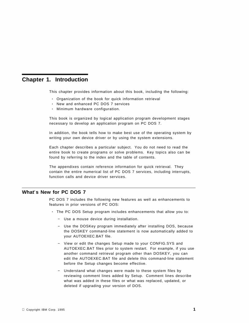
File HandlesThe open or create function calls return a 16-bit value called a file handle.To perform file I/O, a program uses the file handle to reference the file.Once a file is opened, the program no longer needs to maintain the ASCIIZstring pointing to the file. PC DOS 7 keeps track of the location of the file,regardless of which directory is current.
The number of file handles that can be open at one time by all processes canbe specified with the FILES command in CONFIG.SYS. There are 20 defaulthandles available to a single process. All handles inherited by a processcan be redirected.
Each open handle is associated with a single file or device, but severalhandles can reference the same file or device. Thus, the maximum handlelimit can exceed the number specified with the FILES command.
ActivityFunctionNumber
Specifying an additional file handle for a file 45H
Pointing the existing file handle to another file 46H
Specifying the number of open file handles 67H
Special File HandlesPC DOS 7 provides five special file handles for use by application programs.The handles are:
0000H Standard input device (STDIN)
0001H Standard output device (STDOUT)
0002H Standard error device (STDERR)
0003H Standard auxiliary device (STDAUX)
0004H Standard printer device (STDPRN)
File handles associated with standard devices do not need to be opened by aprogram, but a program can close them. STDIN should be treated as aread-only file. STDOUT and STDERR should be treated as write-only files.STDIN and STDOUT can be redirected. Function calls 01H through 0CHaccess the standard devices.
The standard device handles are useful for performing I/O to and from theconsole device. For example, you can read input from the keyboard usingthe read function call (3FH) and file handle 0000H (STDIN); you can also write
16 PC DOS 7

output to the console screen with the write function call (40H) and file handle0001H (STDOUT).
If you want to prevent redirection of your output to STDOUT, you can send itusing file handle 0002H (STDERR). This facility also is useful for errormessages or prompts to the user.
Reading and Writing Data to a FilePC DOS 7 provides five functions to allow reading and writing to a file ordevice, specifying the offset within a file at which the read or write is tooccur, and verifying the read-after-write state. The verification operation,however, slows performance.
ActivityFunctionNumber
Reading from a file or device 3FH
Writing to a file or device 40H
Specifying the address (through the pointer) at which a read or write isto occur
42H
Requesting the read-after-write state 54H
Specifying the read-after-write state 2EH
Requesting and Specifying File AttributesWhile a file is being created, your program can specify certain attributes; forexample, the date and time of creation and level of access.
ActivityFunctionNumber
Requesting and specifying a file′s attributes 43H
Requesting and specifying a file′s date and time 57H
Accessing SubdirectoriesSubdirectories, that is, directories other than the root directories, are files.There is no limit to the number of subdirectory entries if the physical mediacan accommodate them. All directory entries are 32 bytes long.
Note: Values are in hexadecimal.
Chapter 3. Accessing Files with File Handles 17

Each entry in the root directory consists of 32 bytes that are described in thefigure following:
00H ┌────────────────────────────────────┐│ ││ ││ Filename ││ │
08H ├────────────────────────────────────┤│ Extension ││ │
0BH ├────────────────────────────────────┤│ File Attribute │
0CH ├────────────────────────────────────┤│ ││ Reserved ││ ││ │
16H ├────────────────────────────────────┤│ Time created or last updated │
18H ├────────────────────────────────────┤│ Date created or last updated │
1AH ├────────────────────────────────────┤│ Starting Cluster │
1CH ├────────────────────────────────────┤│ ││ ││ File Size (4 bytes) ││ │
20H └────────────────────────────────────┘
The FilenameBytes 0 through 7 represent the filename. The first byte of the filenameindicates the status of the filename. The status of a filename can contain thefollowing values:
00H Filename never used. To improve performance, this value is used tolimit the length of directory searches.
05H The first character of the filename has an E5H character.
E5H Filename has been used, but the file has been erased.
18 PC DOS 7

2EH The entry is for a directory. If the second byte is also 2EH, the clusterfield contains the cluster number of this directory′s parent directory.(Cluster number 0000H is specified if the parent directory is the rootdirectory.)
Any other character is the first character of a filename.
Note: Byte offsets are in decimal.
.
The Filename ExtensionBytes 8 through 10 indicate the filename extension.
The File AttributeByte 11 indicates the file′s attribute. The attribute byte is mapped as follows:
01H Indicates a read-only file. An attempt to open the file for output usingfunction call 3DH or 6CH results in an error code being returned.
02H Indicates a hidden file. The file is excluded from normal directorysearches.
04H Indicates a system file. The file is excluded from normal directorysearches.
08H Indicates the entry contains the volume label in the first 11 bytes. Theentry contains no other usable information and may exist only in theroot directory.
10H Indicates the entry defines a subdirectory and is excluded from normaldirectory searches.
20H Indicates an archive bit. The bit is set ON when the file has beenwritten to and closed. It is used by the BACKUP and RESTOREcommands for determining whether the file has been changed since itwas created or last updated. This bit can be used along with otherattribute bits.
All other bits are reserved and must be 0.
The File Creation/Last Changed TimeBytes 22 and 23 contain the time when the file was created or last updated.The time is mapped in the bits as follows:
< 23 > < 22 >15 14 13 12 11 10 9 8 7 6 5 4 3 2 1 0h h h h h m m m m m m x x x x x
Where:
Chapter 3. Accessing Files with File Handles 19

hh = the binary number of hours (0-23)mm = the binary number of minutes (0-59)xx = the binary number of two-second increments
The time is stored with the least significant byte first.
The File Creation DateBytes 24 and 25 contain the date when the file was created or last updated.The date (mm/dd/yy) is mapped in the bits as follows:
< 25 > < 24 >15 14 13 12 11 10 9 8 7 6 5 4 3 2 1 0y y y y y y y m m m m d d d d d
Where:
yy = 0 − 1 1 9 ( 1 9 8 0 − 2 0 9 9 )mm = 1 − 1 2dd = 1 − 3 1
The date is stored with the least significant byte first.
The Starting Cluster NumberBytes 26 and 27 contain the cluster number of the first cluster in the file. Thefirst cluster for data space on all hard disks and diskettes is cluster 002. Thecluster number is stored with the least significant byte first.
< 27 > < 26 >0 0 0 0 0 0 0 0 0 0 1 0 0 0 0 1
The File SizeBytes 28 through 31 contain the file size in bytes. The first word contains thelow-order part of the size. Both words are stored with the least significantbyte first.
Accessing DirectoriesPC DOS 7 provides four functions within interrupt 21H to create, identify,change or delete directories.
ActivityFunctionNumber
Removing a subdirectory 3AH
Creating a subdirectory 39H
Changing to another directory 3BH
Identifying the current directory 47H
20 PC DOS 7

Finding Files in DirectoriesPC DOS 7 provides two functions within interrupt 21H to search for the firstmatching entry and the next matching entry.
ActivityFunctionNumber
Searching for the first matching entry 4EH
Searching for the next matching entry 4FH
Requesting and Specifying National Language Support (NLS)PC DOS 7 provides the following functions for NLS:
ActivityFunctionNumber
Specifying the current country 38H
Requesting the country dependent information 38H
Providing double-byte character set (DBCS) support 65H
Controlling Network OperationsSeveral PC DOS 7 function calls accept a network path as input if the IBM PCLocal Area Network support is loaded. If network access is available, furtherinformation is noted in the ″Comments″ section under each relevant functioncall in Appendix B, “PC DOS 7 Function Calls” on page 133.
A network path consists of an ASCII string containing a computer name,adirectory path, and an optional filename. The network path cannot contain adrive specifier. The path is terminated by a byte of binary 0′s. Following isan example:
SERVER1LEVEL1LEVEL2FILE1
Many function calls that accept an ASCIIZ string as input accept a networkpath. If you want to execute function 5BH (Create a New File), for example,you must have Read/Write/Create or Write/Create access to the directory tobe able to create a file. If you have Read Only or Write Only access and noCreate access, you cannot create a file in the directory. Two function callsthat do not accept a network path as input are Change Current Directory(3BH) and Find First Matching File (4EH).
Chapter 3. Accessing Files with File Handles 21

The following function calls are available to control network operations:
ActivityFunctionNumber
Locking and unlocking read/write access to a region of a file 5CH
Writing all data from a file to a device 68H
Requesting the local computer ID 5E00H
Specifying the printer setup string 5E02H
Requesting the printer setup string 5E03H
Requesting redirection 5F02H
Attaching to a redirect device 5F03H
Canceling redirect ion 5F04H
22 PC DOS 7

Chapter 4. Accessing Files Using File Control Blocks
This chapter provides guide and system architecture information to assist inperforming the following tasks:
• Accessing files• Accessing sequential records• Accessing random records• Finding files in directories
The File Control Block (FCB)With few exceptions, a program should maintain files using File ControlBlocks (FCBs) only to run under DOS 1.10. File handles are therecommended method for accessing files.
One FCB maintained by your program and PC DOS 7 is required for eachopen file. Your program must supply a pointer to the FCB and fill in theappropriate fields required by specific function calls.
A program should not attempt to use the reserved fields in the FCB. Bytes 0through 15 and 32 through 36 must be set by the user program. Bytes 16through 31 are set by PC DOS 7 and must not be changed by user programs.
An unopened FCB consists of the FCB prefix (if used), the drive number, thefilename, and the extensions appropriately specified. An open FCB is one inwhich the remaining fields have been specified by the create or openfunction calls.
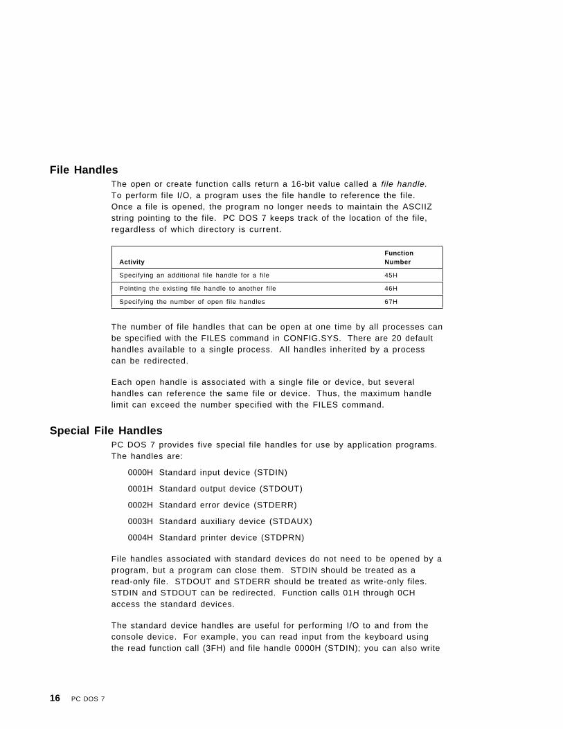
All word fields are stored with the least significant byte first. For example, arecord length of 128 is stored as 80H at offset 14, and 00H at offset 15.Figure 2 on page 24 gives further explanation.
Copyright IBM Corp. 1995 23
-7 ┌───────┬────────────────────────────────────┬──────────┐│ │ │ │ FCB│ hex FF│ Zeros │ Attribute│ extension
0┌───────┼───────┴────────────────────────────────────┴──────────┤│ │ │ Standard│ Drive │ Filename (8bytes) or reserved device name │ FCB8├───────┼───────────────────────┬───────────────┬───────────────┤│ │ │ │ ││ │ Filename extension │ Current block │ Record size │
16├───────┴───────┬───────────────┼───────────────┼───────────────┤ │ File size │ File size │ │ │ │ (low part) │ (high part) │ Date │ │24├───────────────┴───────────────┴───────────────┘ │ │ │
│ Reserved for system use │ 32├───────┬───────────────┬───────────────┬───────────────────────┘
│Current│ Random record │Random record ││record │number (low pt)│number(high pt)│└───────┴───────────────┴───────────────┘
Figure 2. The File Control Block
Areas 16 through to 31 are filled in by DOS and must not be modified.
Other areas are filled in by the using program.
Note: Offsets are in decimal.
The FCB is formatted as follows:
Drive NumberByte 0 represents the drive number. For example, before the file is opened,0 equals the default drive, 1 equals drive A, and 2 equals drive B. After thefile is opened, 0 equals drive A, 1 equals drive A, and 2 equals drive B.
The actual drive number replaces the 0 when a file is opened.
FilenameBytes 1 through 8 represent the filename, left-justified with trailing blanks. Ifa reserved device name such as LPT1 is specified here, do not include thecolon.
24 PC DOS 7

Filename ExtensionBytes 9 through 11 represent the filename extension, left-justified with trailingblanks or all blanks.
Current Block NumberBytes 12 through 13 represent the current block number relative to thebeginning of the file, starting with 0. The 0 is set by the open function call. Ablock consists of 128 records, each size specified in the logical record sizefield. The current block number is used with the current record field forsequential reads and writes.
Logical Record SizeBytes 14 through 15 represent the logical record size in bytes. 80H is set bythe open function call. If you want to change the logical record size from80H, you can reset the value. PC DOS 7 uses the value to determinelocations in the file for all disk reads and writes.
File SizeBytes 16 through 19 represent file size in bytes. In this two-word field, thefirst word is the low-order part of the size.
File DateBytes 20 through 21 represent the date the file was created or last updated.The date (mm/dd/yy) is mapped in the bits as follows:
< 21 > < 20 >15 14 13 12 11 10 9 8 7 6 5 4 3 2 1 0y y y y y y y m m m m d d d d d
where:
yy is 0-119 (1980-2099)mm is 1-12dd is 1-31
ReservedBytes 22 through 31 are reserved.
Record Number in BlockByte 32 represents the current relative record number (0-127) within thecurrent block. You must set this field before doing sequential read and writeoperations to the diskette. This field is not initialized by the open functioncall.
Chapter 4. Accessing Files Using File Control Blocks 25

Record Number within FileBytes 33 through 36 represent the record number relative to the beginning ofthe file, starting with 0. You must set this field before doing random readand write operations to the diskette. This field is not initialized by the openfunction call.
If the record size is less than 64 bytes, both words are used. If the recordsize is more than 64 bytes, only the first 3 bytes are used. Note that if youuse the FCB at 5CH in the program segment, the last byte of the FCBoverlaps the first byte of the unformatted parameter area.
The Extended FCBThe extended FCB is used to create or search in the disk directory for fileswith special attributes. The extension adds a 7-byte prefix to the FCB,formatted as follows:
Extended FCBFCB byte -7 contains FFH to indicate an extended FCB.
ReservedFCB bytes -6 to -2 are reserved.
File AttributeFCB byte -1 represents an attribute byte. Function calls 00H through 2EH arevalid for both the standard FCB and the extended FCB. If you are using anextended FCB, the appropriate register should be set to the first byte of theprefix, rather than the drive number field.
The Disk Transfer Area (DTA)PC DOS 7 uses a buffer in memory, the Disk Transfer Area (DTA), to hold thedata for FCB file reads and writes. The DTA can be at any location withinthe data area of your program and should be specified by your program.
Only one DTA can be in effect at a time, so your program must tell PC DOS 7which memory location to use before issuing disk read or write functions.When a program is given control by COMMAND.COM, a default DTA largeenough to hold 128 bytes is established at 80H in the program segmentprefix.
PC DOS 7 provides the following functions within interrupt 21H to handle DTAactivities:
26 PC DOS 7

ActivityFunctionNumber
Specifying the buffer address for reading and writing data in the DTA 1AH
Requesting the buffer address for reading and writing data in the DTA 2FH
Accessing FilesAn FCB can identify a file on any valid drive, but only in the current directoryof the specified drive.
If SHARE has not been loaded, the number of files that can be open at a time(using FCB function calls) is not restricted. When file sharing is loaded,however, the maximum number of FCB opened files is limited by the valuespecified in the FCBS command in CONFIG.SYS. The m value specifies thetotal number of files that can be opened by FCBS.
When the maximum number of FCB opens is exceeded, PC DOS 7automatically closes the least recently used file. Any attempt to access sucha file results in the interrupt 24H critical error message, “FCB not available.”If this situation occurs while a program is running, the value specified for min the FCBS command should be increased.
Do not use the same FCB to open a second file without closing the first openfile. If more than one file is to be opened concurrently, use separate FCBs.To avoid potential file sharing problems, close files after I/O is performed.Close the file before trying to delete or rename an open file.
Managing files using the FCBS command can be performed using thefollowing function calls:
ActivityFunctionNumber
Opening a file 0FH
Closing a file 10H
Deleting a file 13H
Creating a file 16H
Renaming a file 17H
Requesting the file size 23H
Separating the fi lename information into its components (parsing) 29H
Chapter 4. Accessing Files Using File Control Blocks 27

Accessing Sequential RecordsBy using the current block, current record, and record length fields of theFCB, you can perform sequential I/O by using the following sequential reador write function calls within interrupt 21H:
ActivityFunctionNumber
Reading from a record 14H
Writing to a record 15H
Accessing Random RecordsRandom I/O can be performed by filling in the random record and recordlength fields in the FCB and issuing the following function calls withininterrupt 21H:
ActivityFunctionNumber
Reading from a single record 21H
Writing to a single record 22H
Specifying the random record field in the FCB 24H
Reading from multiple records 27H
Writing to multiple records 28H
Finding Files in DirectoriesUsing the FCB as a source, finding and changing files in directories isperformed by the following functions within interrupt 21H:
ActivityFunctionNumber
Searching for the first matching file entry 11H
Searching for the next matching file entry 12H
Deleting a file 13H
Creating a file 16H
Renaming a file 17H
Separating the fi lename information into its components (parsing) 29H
28 PC DOS 7

Chapter 5. Managing Device I/O
This chapter provides guide and system architecture information about thefollowing tasks:
• Managing display I/O• Managing keyboard I/O• Managing miscellaneous I/O• Managing file system activities• Accessing the system device drivers′ control channel.
Managing Display I/OPC DOS 7 provides four functions within interrupt 21H that send characters orstrings of characters to the screen.
For further information on specifying character attributes, foreground andbackground screen colors, and screen size using ANSI.SYS, see the PC DOS7 User′s Guide and Reference.
ActivityFunctionNumber
Outputting a character to the screen, with the ability to trigger thecontrol-break interrupt handler
02H
Waiting until a character is input and outputting it to the screen withoutthe abil ity to trigger the control-break interrupt handler
06H
Outputting a string of characters in memory to the screen 09H
Outputting a string of characters in a buffer to the screen or writing thestring to a file device
40H
Managing Keyboard I/OPC DOS 7 provides a full complement of functions within interrupt 21H thatyour application program can use to manage keyboard I/O.
ActivityFunctionNumber
Sending input from the keyboard (with echo) to the display 01H
Receiving input directly from the keyboard, or sending output directly tothe display
06H
Receiving input directly from the keyboard without echo 07H
Copyright IBM Corp. 1995 29

For further information on reassigning the keys using ANSI.SYS, see the PCDOS 7 User′s Guide and Reference.
ActivityFunctionNumber
Receiving input from the keyboard without echo to the display with theabil ity to trigger the control-break interrupt handler
08H
Reading characters from the keyboard to the buffer 0AH
Checking the keyboard buffer status 0BH
Clearing the keyboard buffer; specifying which function to call afterclearing the buffer
0CH
Managing Miscellaneous I/OThree functions are available to manage miscellaneous I/O.
ActivityFunctionNumber
Receiving auxil iary input 03H
Sending auxil iary output 04H
Printing output 05H
Managing File System ActivitiesThe following system activities are supported by PC DOS 7:
ActivityFunctionNumber
Requesting the local computer ID 5E00H
Specifying the printer setup string 5E02H
Requesting the printer setup string 5E03H
Requesting redirection l ist 5F02H
Attaching to a redirect device 5F03H
Canceling redirect ion 5F04H
Writing all data from a file to a device 68H
30 PC DOS 7

Accessing the System Device Drivers ′ Control ChannelFunction 44H within interrupt 21H is a multi-purpose function for accessingthe device drivers′ control channel. Using function 44H, your applicationprogram can request the status of a device and read and write to the I/Ocontrol channel. The following subfunction values should be passed in AL:
Category ActivitySubfunctionNumber
Requesting and specifying deviceinformation
Requesting device information 00H
Specifying device information 01H
Reading and writing data to acharacter device
Reading from a character device 02H
Writing to a character device 03H
Reading and writing data to ablock device
Reading from a block device 04H
Writing to a block device 05H
Requesting and specifying deviceinformation
Determining whether a devicecontains removable media
08H
Providing network support fordevices
Determining whether a logicaldevice is local or remote
09H
Determining whether a fi le handleis local or remote
0AH
Specifying how many times (andintervals) PC DOS 7 should try toresolve shared fi le conflicts
0BH
Controlling I/O for fi le handles 0CH
Controlling I/O for block devices 0DH
Requesting and specifying thelogical drive
Requesting the logical drive 0EH
Specifying the logical drive 0FH
Chapter 5. Managing Device I/O 31

Reading and Writing Data in Binary and ASCII ModesA program can use function 44H to change the mode in which data is read orwritten to a device. If I/O is performed in binary mode, control values haveno meaning. If I/O is performed in ASCII mode, certain control values havemeaning. They are shown in the following table:
When a file is read in ASCII mode, it is echoed to the display and tabs areexpanded into spaces. They are left as a tab byte (09H) in the input buffer.When a file is written in ASCII mode, tabs are expanded to 8-characterboundaries and filled with spaces (20H).
ControlValue
KeyboardInput Meaning
03H ∧C Control Break
04H ∧D End of Task
10H ∧P Print Screen
11H ∧Q Scroll restart
13H ∧S Scroll Lock
0AH ∧J Line Feed
0DH ∧ M Carriage Return
1AH ∧ Z End-Of-File
32 PC DOS 7

Chapter 6. Controlling Processes
This chapter provides guide and system architecture information about thefollowing activities:
• Allocating memory• Identifying a program at load time• Loading and executing overlays• Terminating a program/subprogram• Loading an overlay without executing it• Calling a command processor• Responding to errors• Responding to a control-break action• Requesting and specifying the system date and time• Requesting and specifying the interrupt vectors.
Allocating MemoryPC DOS 7 keeps track of allocated and available memory blocks andprovides three function calls for application programs to communicate theirmemory requests.
ActivityFunctionNumber
Allocating memory 48H
Freeing allocated memory 49H
Changing the size of blocks of allocated memory 4AH
PC DOS 7 Memory ManagementPC DOS 7 manages memory by allocating 16-byte units called paragraphsand building a control block for each allocated block. Any allocation is 16bytes larger than the actual request because PC DOS 7 automaticallyallocates a control block to keep track of each allocated block.
When the user starts the program at the command line, COMMAND.COMloads the executable program module into the largest unused block ofavailable memory and reads the file header. If there is not enough memoryavailable, the system returns an error code and passes control to theprogram. Your program should use the SETBLOCK function call (4AH) toreduce allocated memory to the size it needs.
Copyright IBM Corp. 1995 33

Note: Because it is likely that the default stack supplied by PC DOS 7 lies inthe area of memory being freed, a .COM program should remember toset up its own stack before issuing a SETBLOCK. The SETBLOCK callfrees unneeded memory which then can be used for loadingsubsequent programs.
If your program requires additional memory during processing, issue functioncall 48H within interrupt 21. To free memory, issue function call 49H withininterrupt 21.
The PC DOS 7 Memory MapThe following table illustrates the order in which PC DOS 7 components andapplication programs are located in memory when PC DOS 7 is loaded lowand no HMA exists.
The following table illustrates the order in which the PC DOS 7 componentsand application programs are located in memory when PC DOS 7 is loadedhigh.
Location Use
0000:0000 Interrupt vector table
0040:0000 ROM communication area
0050:0000 PC DOS 7 communication area
0070:0000 IBMBIO.COM − PC DOS 7 interface to ROM I/O routines
XXXX:0000 IBMDOS.COM − PC DOS 7 interrupt handlers, service routines (INT 21functions)
XXXX:0000 PC DOS 7 buffers, control areas, and installed device drivers
XXXX:0000 Resident portion of COMMAND.COM − Interrupt handlers for interrupts22H (terminate), 23H (Ctrl-Break), 24H (critical error), and code to reloadthe transient portion
XXXX:0000 External command or util ity − . COM or .EXE file
XXXX:0000 User stack for .COM files
XXXX:0000 Transient portion of COMMAND.COM
Location Use
0000:0000 Interrupt vector table
0040:0000 ROM communication area
0050:0000 PC DOS 7 communication area
0070:0000 Resident BIOS data − also including device driver headers and entrypoints
XXXX:0000 PC DOS 7 data
34 PC DOS 7

Memory map addresses are in segment:offset format. For example,0070:0000 is absolute address 00700H.
Note: The VDISK header is placed at the start of the HMA as a precautionbecause most INT 15 allocations respect VDISK headers.
The PC DOS 7 Communication Area is used as follows:
0050:0000 Print screen status flag store
0 Print screen not active or successful print screen operation
1 Print screen in progress
255 Error encountered during print screen operation
0050:0001 Used by BASICA
0050:0004 Single-drive mode status byte
0 Diskette for drive A was last used
1 Diskette for drive B was last used
0050:0010—0021 Used by BASICA
0050:0022—002F Used by PC DOS 7 for diskette initialization
0050:0030—0033 Used by MODE command.
All other locations within the 256 bytes beginning at 0050:0000 are reservedfor PC DOS 7 use.
Location Use
XXXX:0000 PC DOS 7 installable device drivers and data structures that areallocated by SYSINIT
FFFF:0010 VDISK header (see note below)
FFFF:0030 IBMBIO
XXXX:XXXX IBMDOS
Chapter 6. Control l ing Processes 35

Identifying a Program at Load TimePC DOS 7 provides two function calls for application programs to specify andidentify themselves at load time:
ActivityFunctionNumber
Creating the means for PC DOS 7 to identify a program at load timethrough the program segment prefix (PSP)
26H
Requesting how PC DOS 7 identified a program at load time 62H
The Program SegmentWhen you enter an external command or call a program with the EXECfunction call (4BH), PC DOS 7 determines the lowest available address inmemory and assigns it to the program. That area of memory is called theprogram segment. At offset 0 within the program segment, PC DOS 7 buildsa program segment prefix control block. When an EXEC is issued, PC DOS 7loads the program at offset 100H and gives it control. See Figure 3 onpage 37 for an illustration of the program segment prefix.
36 PC DOS 7

┌───────┬───────┬───────┬───────┬───────┬───────┬───────┬───────┐│ 0 │ 1 │ 2 │ 3 │ 4 │ 5 │ 6 │ 7 │├───────┴───────┼───────┴───────┼───────┴───────┴───────┴───────┤│ INT │ Top of │ ││ 20H │ memory │ Reserved │├───────┬───────┼───────┬───────┼───────┬───────┬───────┬───────┤│ 8 │ 9 │ A │ B │ C │ D │ E │ F │├───────┴───────┼───────┴───────┼───────┴───────┼───────┴───────┤│ │ Terminate │ Terminate │ Ctrl-break ││ Reserved │ address │ address │ exit address ││ │ IP │ CS │ IP │├───────┬───────┼───────┬───────┼───────┬───────┼───────┬───────┤│ 10 │ 11 │ 12 │ 13 │ 14 │ 15 │ 16 │ 17 │├───────┴───────┼───────┴───────┴───────┴───────┼───────┴───────┤│ Ctrl-break │ Critical error │ ││ exit address │ exit address │ Reserved ││ CS │ IP CS │ │├───────────────┴───────────────┬───────┬───────┼───────┬───────┤│ 18 to 2B │ 2C │ 2D │ 2E │ 2F │├───────────────────────────────┼───────┴───────┼───────┴───────┤│ │ Environment │ ││ Reserved │ pointer │ Reserved │├───────────────────────────────┴───────────────┴───────────────┤│ 30 to 4F │├───────────────────────────────────────────────────────────────┤│ Reserved │├───────┬───────┬───────┬───────┬───────┬───────┬───────┬───────┤│ 50 │ 51 │ 52 │ 53 │ 54 │ 55 │ 56 │ 57 │├───────┴───────┼───────┴───────┴───────┴───────┴───────┴───────┤│ DOS call │ Reserved │├───────┬───────┼───────┬───────┬───────┬───────┬───────┬───────┤│ 58 │ 59 │ 5A │ 5B │ 5C │ 5D │ 5E │ 5F │├───────┴───────┴───────┴───────┼───────┴───────┴───────┴───────┤│ Reserved │ Unopened Standard FCB1 │├───────┬───────┬───────┬───────┼───────┬───────┬───────┬───────┤│ 60 │ 61 │ 62 │ 63 │ 64 │ 65 │ 66 │ 67 │├───────┴───────┴───────┴───────┴───────┴───────┴───────┴───────┤│ Unopened Standard FCB1 (continued) │├───────┬───────┬───────┬───────┬───────┬───────┬───────┬───────┤│ 68 │ 69 │ 6A │ 6B │ 6C │ 6D │ 6E │ 6F │├───────┴───────┴───────┴───────┼───────┴───────┴───────┴───────┤│ Unopened Standard FCB1 │ Unopened Standard FCB2 ││ (continued) │ │├───────┬───────┬───────┬───────┼───────┬───────┬───────┬───────┤│ 70 │ 71 │ 72 │ 73 │ 74 │ 75 │ 76 │ 77 │├───────┴───────┴───────┴───────┴───────┴───────┴───────┴───────┤│ Unopened Standard FCB2 (continued) │├───────┬───────┬───────┬───────┬───────┬───────┬───────┬───────┤│ 78 │ 79 │ 7A │ 7B │ 7C │ 7D │ 7E │ 7F │├───────┴───────┴───────┴───────┴───────┴───────┴───────┴───────┤│ Unopened Standard FCB2 (continued) │├───────┬───────┬───────┬───────┬───────┬───────┬───────┬───────┤│ 80 │ 81 │ 82 │ 83 │ 84 │ 85 │ 86 │ 87 │├───────┼───────┴───────┴───────┴───────┴───────┴───────┴───────┤│ Param │ Command parameters ┴│ Length│ starting with leading blanks ┬├───────┼───────┬───────┬───────┬───────┬───────┬───────┬───────┤│ F8 │ F9 │ FA │ FB │ FC │ FD │ FE │ FF │├───────┴───────┴───────┴───────┴───────┴───────┴───────┴───────┤┴ │┬ Command parameters │└───────────────────────────────────────────────────────────────┘
Figure 3. The Program Segment Prefix
Chapter 6. Control l ing Processes 37

The program segment prefix′s first segment of available memory is inparagraph form; that is, 1000H represents 64KB. The word at offset 6contains the number of bytes available in the segment.
Offset 2CH contains the environment′s paragraph address.
Offset 50H contains code to invoke the PC DOS 7 function dispatcher. Byplacing the desired function number in AH, a program can issue a long callto PSP+50H to invoke a PC DOS 7 function rather than issuing an interrupt21H.
The default disk transfer address is set to 80H.
An unformatted parameter area at 81H contains all the characters enteredafter the command name, including leading and imbedded delimiters, with80H set to the number of characters. I f the <, >, or | parameters wereentered on the command line, they and the filenames associated with themwill not appear in this area because redirection of standard input and outputis transparent to applications.
For .COM files, offset 6 (one word) contains the number of bytes available inthe segment.
Register AX contains the drive specifiers entered with the first twoparameters as follows:
AL=FFH if the first parameter contained an invalid drive specifier(otherwise AL=00H).AH=FFH if the second parameter contained an invalid drive specifier(otherwise AH=00H).
In .EXE programs DS and ES registers are set to point to the programsegment and CS, IP, SS, and SP registers are set to the values passed by theLinker.
In .COM programs all four segment registers contain the segment address ofthe initial allocation block, starting with the program segment prefix controlblock. The instruction pointer (IP) is set to 100H. The SP register is set tothe end of the program′s segment. The segment size at offset 6 is roundeddown to the paragraph size.
38 PC DOS 7

Loading and Executing OverlaysYour program can use the 4BH function call to load optional overlays.Function 4BH, value 0, loads and executes a program with overlays.Function 4BH, value 3, loads an overlay without executing it.
If your program calls an overlay, the EXEC call assumes the calling programhas already allocated memory for the overlay. The request to load anoverlay does not verify that the calling program owns the memory into whichthe overlay is to be loaded. An overlay loaded into memory not allocated toit can damage the PC DOS 7 memory management control blocks. This willnot be evident until PC DOS 7 needs to use its series of control blocks.
If a memory allocation error is returned, the problem must be corrected andthe system restarted. Overlays should not issue SETBLOCK calls becausethey do not own the memory in which they operate. The memory iscontrolled by the calling program.
The Parameter BlockWhen your program calls a subprogram using the EXEC call (4BH), it canpass a parameter block which provides the subprogram with the following:
• The environment string• A command line which permits it to act like another command processor• File control blocks at 5C and 6C in the program segment prefix
(optional).
The Environment StringThe environment passed from the calling program is a copy of itsenvironment. The segment address of the passed environment is containedat offset 2CH in the program segment prefix.
The environment is a series of ASCII strings totaling less than 32KB in theform:
NAME=parameter
Note: NAME= is always in uppercase.
Each string is terminated by a byte of 0′s. The complete series of strings isterminated by another byte of 0′s. Another ASCII string containing the wordcount and an ASCIIZ string containing the executable program′s drive, path,filename, and extension follow the series of environment strings.
The environment built by the command processor and passed to all calledprograms contains a COMSPEC= string, the last PATH, APPEND and
Chapter 6. Control l ing Processes 39

PROMPT commands issued, and any environment strings specified with theSET command.
The Command LineYour program must create a command line which will be transferred to thesubprogram.
The File Control BlocksIf your program is using files based on file handles, the file control blocks areof no concern. If your program is using file control blocks, and either 5CH or6CH contain a pathname, the corresponding FCB will contain only a validdrive number. The filename field will not be valid.
Terminating a Program/SubprogramPC DOS 7 provides four functions and two interrupts to terminate programs.It also provides an interrupt to permit your program to specify where controlis to be passed upon termination.
Interrupt 20H terminates a program. Interrupt 27H terminates a program witha specified portion remaining in memory. Interrupt 22H specifies wherecontrol is to be passed upon program termination.
When a subprogram terminates, control is returned to the calling program.Before terminating, the calling program must return to the system thememory it allocated to the subprogram. When the calling programterminates, control is returned to PC DOS 7. PC DOS 7 does a CHECKSUMto determine if the transient portion of COMMAND.COM has been modified.If it has, PC DOS 7 reloads COMMAND.COM based on the path specified inthe environment.
The program returns from executing in one of the following methods:
• By a jump to offset 0 in the program segment prefix• By issuing an INT 20H• By issuing an INT 21H with register AH=00H or 4CH
ActivityFunctionNumber
Terminating a program 00H
Terminating a program with a specified portion remaining in memory 31H
Terminating a program and passing control to the calling process 4CH
Determining how a process ended 4DH
40 PC DOS 7

• By calling location 50H in the program segment prefix with AH=00H or4CH.
Using INT 21H is the preferred method. All programs must ensure that theCS register contains the segment address of the program segment prefixwhen terminating using any of the preceding methods except call 4CH.
All of the preceding methods return control to the program that issued theEXEC. During the process, interrupt vectors 22H, 23H, and 24H (terminate,Ctrl-Break, and critical error exit addresses) are restored from the valuessaved in the program segment prefix of the terminating program. Control isthen given to the terminating address.
Loading an Overlay without Executing ItIf AL=3 is specified within function call 4BH, no program segment prefix isbuilt, and DOS assumes the calling program has allocated memory for theoverlay. The calling program should provide memory in one of two ways:
• Provide enough memory for the overlay when it issues the SETBLOCKcall (4AH)
• Free adequate memory with the 49H call.
When DOS receives an AL=3 request, the system assumes that therequested memory is owned by the calling program. As in subprograms, anoverlay can be loaded into memory not allocated to it and damage the seriesof DOS memory management control blocks.
Programs loaded with AL=3 should not issue the SETBLOCK call (4AH)because the memory in which they operate is owned by the calling process,not the overlay. Before terminating, the calling program must return to thesystem the memory it allocated to the overlay. When the calling programterminates, control is returned to DOS.
Calling a Command ProcessorTo call a command processor, you must do the following:
• Assure that adequate free memory is available to contain the secondcopy of the command processor and the command it is to execute. Issuefunction call 4AH to shrink allocated memory to your currentrequirement. Issue function call 48H with BX=FFFFH. The return isavailable memory.
• Build a parameter string for the secondary command processor in theform:
Chapter 6. Control l ing Processes 41

1 byte = length of parameter stringxx by te = parameter string1 byte = 0DH (carriage return)
For example, the following assembly statement builds the string toexecute a DISKCOPY command:
DB 19, ″ /C C:DISKCOPY A: B:″ , 13
• Use the EXEC function call (4BH, function value 0) to execute thesecondary copy of the command processor. The COMSPEC =parameter in the environment passed at PSP+2CH identifies the drive,directory, and command processor name. Remember to set offset 2 inthe EXEC control block to point to the parameter string.
Responding to ErrorsWhen a PC DOS 7 function cannot be performed (indicating a critical errorsituation) control is transferred to interrupt 24H. Function 59H providesadditional information on the error condition.
Handle function calls report an error by setting the carry flag and returningthe error code in AX. FCB function calls report an error by returning FFH inAL.
The Extended Error function call (59H) provides a common set of error codesand specific error information such as error classification, location, andrecommended action. In most critical cases, applications can analyze theerror code and take specific action. Recommended actions are intended forprograms that do not understand the error codes. Programs can takeadvantage of extended error support both from interrupt 24H critical errorhandlers and after issuing interrupt 21H function calls. Do not code tospecific error codes.
Activity Number
Responding to a critical error situation Interrupt 24H
Requesting additional error information and suggested action Function 59H
Responding to a Control-Break ActionInterrupt 23H is issued if a Ctrl-Break occurs during standard I/O. Functioncalls 09H and 0AH can be used if there is a ∧C, carriage return and line feedproduced as output.
42 PC DOS 7

If a Ctrl-Break is entered during standard input, standard output, standardprinter, or asynchronous communications adapter operations, an INT 23H isexecuted. If BREAK is on, INT 23H is checked on most function calls, except06H and 07H.
The user-written Ctrl-Break routine can use function calls 09H, 0AH, and 0DHto respond to the Ctrl-Break action by having ^C, carriage return, and linefeed produced as output. ASCII codes 0DH and 0AH represent carriagereturn and line feed, respectively. If the Ctrl-Break routine saves allregisters, it may end with an IRET (return from interrupt) instruction tocontinue program execution. If the routine returns with a long return, thecarry flag is used to determine whether or not to stop execution. If the carryflag is not set, execution continues, as with an IRET.
There are no restrictions on what the Ctrl-Break handler is allowed to do,providing the registers are unchanged if IRET is used.
Activity FunctionNumber
Displaying str ing 09H
Buffering keyboard input 0AH
Responding to a control-break action 23H
Chapter 6. Control l ing Processes 43

Requesting and Specifying the System Date and TimeThe following functions get or set the system date and time:
ActivityFunctionNumber
Requesting the system date 2AH
Specifying the system date 2BH
Requesting the system time 2CH
Specifying the system time 2DH
Requesting and Specifying the Interrupt VectorsA program can create and change the contents of the interrupt vectors, the4-byte addresses of the routines in memory that service hardware andsoftware interrupts. On exit, the program must reset the interrupt vectors towhere they were pointing originally.
If you want a program to examine or specify the contents of an interruptvector, use PC DOS 7 function calls 35H and 25H and avoid referencing theinterrupt vector locations directly.
ActivityFunctionNumber
Specifying the interrupt vector value 25H
Requesting the interrupt vector value 35H
44 PC DOS 7

Chapter 7. Debugging a Program
This chapter describes how to use the DEBUG.COM program that is shippedas part of PC DOS 7 to identify and fix problems in your programs.
Warning
Use of the DEBUG program should not be undertaken lightly, the utilityhas the power to alter code, always ensure that you take a backup copyof the code that you will be using debug on.
The DEBUG UtilityDEBUG provides a controlled testing environment that enables you tomonitor the execution of a program. You can make changes directly to a.COM or an .EXE file and execute the file immediately to determine whetheryour changes fixed a problem. You do not need to reassemble source codefiles first. DEBUG allows you to load, alter, or display any file and to executeobject files as well.
Starting the DEBUG.COM ProgramTo start DEBUG, enter information in the following format:
DEBUG [ [drive:] [path]filename [testfile-parameters]]
You can enter just the DEBUG command, or you can include a filespecification. The parameters parm1 and parm2 represent input and outputspecifications of the program you are debugging. For example, suppose youwanted to monitor the execution of the PC DOS 7 DISKCOMP utility. Youenter:
DEBUG DISKCOMP.COM A: B:
The DEBUG program loads DISKCOMP into memory and displays the DEBUGprompt:
-
The hyphen (-) tells you DEBUG is ready to accept commands to alter,display, or execute the contents of the program in memory.
Copyright IBM Corp. 1995 45

If you enter just DEBUG without a file specification, you can either work withthe present memory contents or you can load a required file into memoryusing the DEBUG Name and Load commands.
Entering Commands at the DEBUG PromptA DEBUG command consists of a single letter, usually followed by one ormore parameters. For example, the Name command is entered at theDEBUG prompt as a single letter followed by a file specification:
-N MYPROG
A command and its parameters can be entered in uppercase, lowercase, ora combination of both. The command and its parameters can be separatedby delimiters; however, delimiters are only required between twoconsecutive hexadecimal values. Thus, the following Dump commands areequivalent:
dcs:100 110d cs:100 110d,cs:100,110
A command is activated only after you press the Enter key. If you want toterminate a command and return to the DEBUG prompt, simultaneouslypress the Ctrl and Break keys.
For commands producing a large amount of output, you can simultaneouslypress the Ctrl and Num Lock keys (or Pause key if available) to suspend thedisplay and then press any key to restart the display, or you can redirect thecommand ′s output to a file.
When DEBUG encounters a syntax error in a line, it displays the line with theerror identified as follows:
d cs:100 CS:100^error 110
In this example, the Dump command expects the second address to containonly a hexadecimal offset value. It finds the S, which is not a hexadecimalcharacter.
46 PC DOS 7

DEBUG Command SummaryThe table below lists the DEBUG commands and describes the debuggingoperations you can perform with them. Complete format descriptions andexamples for each command can be found starting on page 49.
Command Task Description
A (Assemble) Assemble IBM Macro Assembler statements directly intomemory.
C (Compare) Compare the contents of two blocks of memory.
D (Dump) Dump the contents of a portion of memory to the display orredirect it to a file.
E (Enter) Make changes to bytes in memory.
F (Fill) Fill a range of memory with byte values.
G (Go) Execute the program in memory from one address to thebreakpoint address and then display the next instruction.
H (Hex) Add and subtract two hexadecimal values and display theresults.
I (Input) Display the input in the first byte next to the port.
L (Load) Load the contents of absolute disk sectors or a file specifiedby the Name command into memory.
M (Move) Copy the contents of a block of memory to another location.
N (Name) Set up file control blocks and file specification information forLoad and Write commands.
O (Output) Send a byte to an output port.
P (Proceed) Execute a subroutine call, loop instruction, interrupt, or repeatstring instruction and return control to DEBUG at the nextinstruction.
Q (Quit) End the DEBUG session without saving the debugged program.
R (Register) Display the contents of registers and the settings of flags.
S (Search) Search a range of memory for characters.
T (Trace) Execute one or more instructions in your program and displaythe contents of registers and flags after each instruction.
U (Unassemble) Translate the contents of memory into Assembler-l ikestatements, displaying their addresses and hexadecimalvalues.
W (Write) Write the debugged program to absolute disk sectors or to theoriginal fi le loaded with DEBUG.
XA (Allocate) Allocate a specified number of expanded memory pages to anEMS handle.
XD (Deallocate) Deallocate an EMS handle.
XM (Map) Map an EMS logical page to an EMS physical page from anEMS handle.
XS (Status) Display the status of expanded memory.
Chapter 7. Debugging a Program 47

The DEBUG Work SpaceWhen the DEBUG program starts, the registers and flags are set to thefollowing values for the program being debugged:
• The segment registers (CS, DS, ES, and SS) are set to the bottom of freememory; that is, the first segment after the end of the DEBUG program.
• The Instruction Pointer (IP) is set to hex 0100.• The Stack Pointer (SP) is set to the end of the segment, or the bottom of
the transient portion of the program loader, whichever is lower. Thesegment size at offset 6 is reduced by hex 100 to allow for a stack thatsize.
• The remaining registers (AX, BX, CX, DX, BP, SI, and DI) are set to 0.However, if you start the DEBUG program with a file specification, the CXregister contains the length of the file in bytes. If the file is greater than64KB, the length is contained in registers BX and CX (the high portion inBX).
• The initial state of the flags is:
NV UP EI PL NZ NA PO NC
• The default disk transfer address is set to hex 80 in the code segment.
All of available memory is allocated. At this point, the loaded program isunable to allocate memory.
.EXE FilesIf a file loaded by DEBUG has an extension of .EXE, DEBUG does thenecessary relocation and sets the segment registers, stack pointer, andinstruction pointer to the values defined in the file. The DS and ES registers,however, point to the program segment prefix at the lowest availablesegment. The BX and CX registers contain the size of the program that issmaller than the file size.
The program is loaded at the high end of memory if the appropriateparameter was specified when the linker created the file.
.HEX FilesIf a file loaded by DEBUG has an extension of .HEX, the file is assumed to bein INTEL hex format, and is converted to executable form while being loaded.
48 PC DOS 7

A (Assemble) Command
PurposeAssembles macro assembler language statements directly into memory.
FormatA [address]
Parametersaddress Use any of the following formats:
• A segment register plus an offset, such as CS:0100• A segment address plus an offset, such as 4BA:0100• An offset only, such as 100. In this case, the default
segment is used.
CommentsAll numeric input to the Assemble command is in hexadecimal. Theassembly statements you enter are assembled into memory at successivelocations, starting with the address specified in address. If no address isspecified, the statements are assembled into the area at CS:0100, if noprevious Assemble command was used, or into the location following the lastinstruction assembled by a previous Assemble command. After all desiredstatements have been entered, press the Enter key when you are promptedfor the next statement to return to the DEBUG prompt.
DEBUG responds to invalid statements by displaying:
∧error
and re-displaying the current assemble address.
DEBUG supports standard 8086/8088 assembly language syntax (and the 8087instruction set), with the following rules:
• All numeric values entered are hexadecimal and can be entered as 1through 4 characters.
• Prefix mnemonics are entered in front of the opcode to which they refer.They can also be entered on a separate line.
• The segment override mnemonics are CS:, DS:, ES:, and SS:.
Chapter 7. Debugging a Program 49
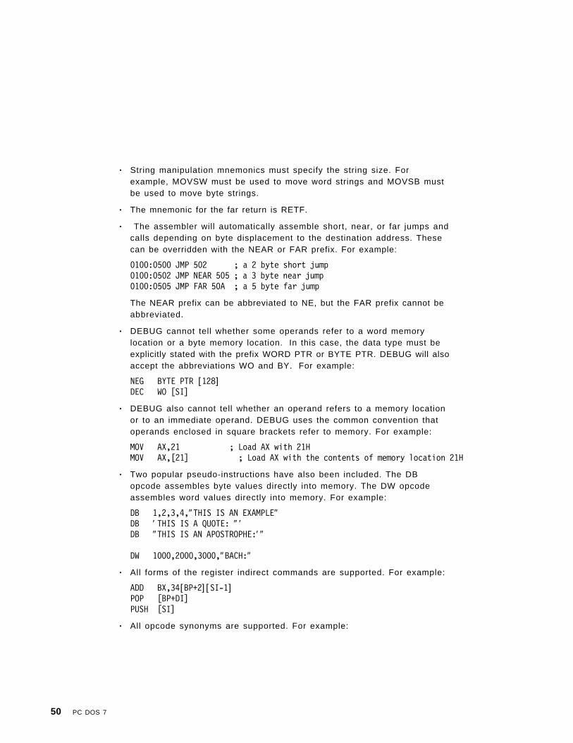
• String manipulation mnemonics must specify the string size. Forexample, MOVSW must be used to move word strings and MOVSB mustbe used to move byte strings.
• The mnemonic for the far return is RETF.
• The assembler will automatically assemble short, near, or far jumps andcalls depending on byte displacement to the destination address. Thesecan be overridden with the NEAR or FAR prefix. For example:
0100:0500 JMP 502 ; a 2 byte short jump0100:0502 JMP NEAR 505 ; a 3 byte near jump0100:0505 JMP FAR 50A ; a 5 byte far jump
The NEAR prefix can be abbreviated to NE, but the FAR prefix cannot beabbreviated.
• DEBUG cannot tell whether some operands refer to a word memorylocation or a byte memory location. In this case, the data type must beexplicitly stated with the prefix WORD PTR or BYTE PTR. DEBUG will alsoaccept the abbreviations WO and BY. For example:
NEG BYTE PTR [128]DEC WO [SI]
• DEBUG also cannot tell whether an operand refers to a memory locationor to an immediate operand. DEBUG uses the common convention thatoperands enclosed in square brackets refer to memory. For example:
MOV AX,21 ; Load AX with 21HMOV AX,[21] ; Load AX with the contents of memory location 21H
• Two popular pseudo-instructions have also been included. The DBopcode assembles byte values directly into memory. The DW opcodeassembles word values directly into memory. For example:
DB 1,2,3,4,″THIS IS AN EXAMPLE″DB ′ THIS IS A QUOTE: ″ ′DB ″THIS IS AN APOSTROPHE:′ ″
DW 1000,2000,3000,″BACH:″
• All forms of the register indirect commands are supported. For example:
ADD BX,34[BP+2] [SI-1]POP [BP+DI]PUSH [SI]
• All opcode synonyms are supported. For example:
50 PC DOS 7

LOOPZ 100LOOPE 100
JA 200JNBE 200
• For numeric co-processor opcodes the WAIT or FWAIT prefix must beexplicitly specified. For example:
FWAIT FADD ST,ST(3) ;This line will assemble a FWAIT prefix
FLD TBYTE PTR [BX] ;This line will not
Examples
C>debug-a20008B4:0200 xor ax,ax08B4:0202 mov [bx],ax08B4:0204 ret08B4:0205
C (Compare) Command
PurposeCompares the contents of two blocks of memory.
FormatC range address
Parametersrange Either of these two formats:
• An address followed by an offset, such as CS:100 110.• An address followed by L value, where value is the number
of hexadecimal bytes to be processed. For example, CS:100L 10.
The limit for range is hexadecimal 10000 or decimal 64KB. Tospecify a range of 64KB within 4 hexadecimal characters, enter0000 or 0 for value.
Chapter 7. Debugging a Program 51

address Any of these three formats:
• A segment register plus an offset, such as CS:0100.• A segment address plus an offset, such as 4BA:0100.• An offset only, such as 100. In this case, the default
segment is used.
CommentsThe contents of the two blocks of memory are compared; the length of thecomparison is determined from the range. If unequal bytes are found, theiraddresses and contents are displayed, in the form:
addr1 byte1 byte2 addr2
where, the first half (addr1 byte1) refers to the location and contents of themismatching locations in range, and the second half (byte2 addr2) refers tothe byte found in address.
If you enter only an offset for the beginning address of range, the Ccommand assumes the segment contained in the DS register. To specify anending address for range, enter it with only an offset value.
ExamplesC 100 L20 200
The 32 bytes (hex 20) of memory beginning at DS:100 are compared with the32 bytes beginning at DS:200. L20 is the range.
D (Dump) Command
PurposeDisplays the contents of a portion of memory.
FormatD [address]
or
D [range ]
52 PC DOS 7

Parametersaddress Any of the following formats:
• A segment register plus an offset, such as CS:0100.• A segment address plus an offset, such as 4BA:0100.• An offset only, such as 100. In this case, the default
segment is used.
range Either of these two formats:
• An address followed by an offset, such as CS:100 110.• An address followed by L value, where value is the number
of hexadecimal bytes to be processed. For example, CS:100L 10.
The limit for range is hexadecimal 10000 or decimal 64K bytes.To specify a range of 64K bytes within 4 hexadecimalcharacters, enter 0000 or 0 for value.
CommentsThe dump is displayed in two parts:
1. A hexadecimal portion. Each byte is displayed in hexadecimal.
2. An ASCII portion. The bytes are displayed as ASCII characters.Unprintable characters (ASCII 0 to 31 and 127 to 255) are indicated by aperiod.
With a 40-column system display format, each line begins on an 8-byteboundary and shows 8 bytes.
With an 80-column system display format, each line begins on a 16-byteboundary and shows 16 bytes. There is a hyphen between the 8th and 9thbytes.
Note: The first line may have fewer than 8 or 16 bytes if the starting addressof the dump is not on a boundary. In this case, the second line of thedump begins on a boundary.
The Dump command has two format options.
Option 1
Use this option to display the contents of hex 40 bytes (40-column mode) orhex 80 bytes (80-column mode). For example:
Chapter 7. Debugging a Program 53

D address
or
D
The contents are dumped starting with the specified address.
If you do not specify an address, the D command assumes the startingaddress is the location following the last location displayed by a previous Dcommand. Thus, it is possible to dump consecutive 40-byte or 80-byte areasby entering consecutive D commands without parameters.
If no previous D command was entered, the location is offset hex 100 into thesegment originally initialized in the segment registers by DEBUG.
Note: If you enter only an offset for the starting address, the D commandassumes the segment contained in the DS register.
Option 2
Use this option to display the contents of the specified address range. Forexample:
D range
Note: If you enter only an offset for the starting address, the D commandassumes the segment contained in the DS register. If you specify anending address, enter it with only an offset value.
For example:
D cs:100 10C
A 40-column display format might look like this:
04BA:0100 42 45 52 54 41 20 54 00BERTA T.
04BA:0108 20 42 4F 52 47BORG
54 PC DOS 7

E (Enter) Command
Purpose• Replaces the contents of one or more bytes, starting at the specified
address, with the values contained in the list (see Option 1).
• Displays and allows modification of bytes in a sequential manner (seeOption 2).
FormatE address [l ist ]
Parametersaddress Any of the following formats:
• A segment register plus an offset, such as CS:0100.• A segment address plus an offset, such as 4BA:0100.• An offset only, such as 100. In this case, the default
segment is used.
list A string of byte values. If you include a character string,enclose the characters in single or double quotation marks. Tospecify a quotation mark as a character within the string when itis also used to delimit the string, type it twice.
″These ″″quotes″″ are correct.″′ This one′ ′ s okay, too.′
CommentsIf you enter only an offset for the address, the E command assumes thesegment contained in the DS register.
The Enter command has two format options.
Option 1
Use this option to place the list in memory beginning at the specifiedaddress.
E address list
For example:
E ds:100 F3 ″xyz″ 8D
Chapter 7. Debugging a Program 55
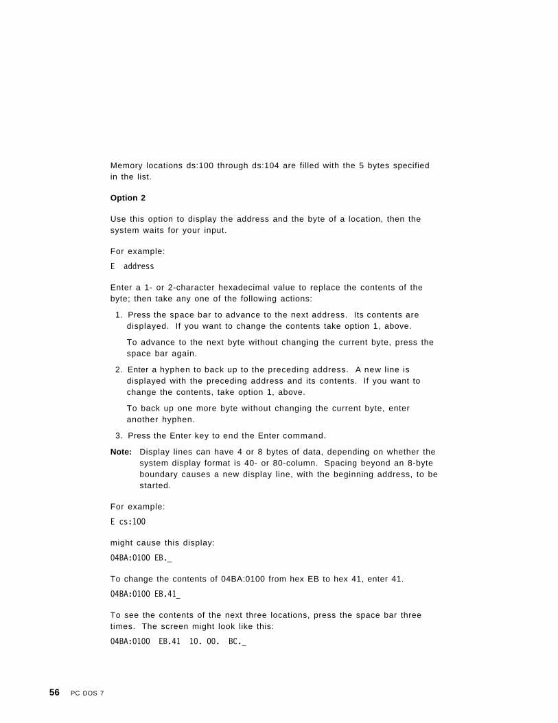
Memory locations ds:100 through ds:104 are filled with the 5 bytes specifiedin the list.
Option 2
Use this option to display the address and the byte of a location, then thesystem waits for your input.
For example:
E address
Enter a 1- or 2-character hexadecimal value to replace the contents of thebyte; then take any one of the following actions:
1. Press the space bar to advance to the next address. Its contents aredisplayed. If you want to change the contents take option 1, above.
To advance to the next byte without changing the current byte, press thespace bar again.
2. Enter a hyphen to back up to the preceding address. A new line isdisplayed with the preceding address and its contents. If you want tochange the contents, take option 1, above.
To back up one more byte without changing the current byte, enteranother hyphen.
3. Press the Enter key to end the Enter command.
Note: Display lines can have 4 or 8 bytes of data, depending on whether thesystem display format is 40- or 80-column. Spacing beyond an 8-byteboundary causes a new display line, with the beginning address, to bestarted.
For example:
E cs:100
might cause this display:
04BA:0100 EB.
To change the contents of 04BA:0100 from hex EB to hex 41, enter 41.
04BA:0100 EB.41
To see the contents of the next three locations, press the space bar threetimes. The screen might look like this:
04BA:0100 EB.41 10. 00. BC.
56 PC DOS 7

To change the contents of the current location (04BA:0103) from hex BC tohex 42, enter 42.
04BA:0100 EB.41 10. 00. BC.42
Now, suppose you want to back up and change the hex 10 to hex 6F. This iswhat the screen looks like after entering two hyphens and the replacementbyte:
04BA:0100 EB.41 10.00. BC.42-04BA:0102 00.-04BA:0101 10.6F
Press the Enter key to end the Enter command. The hyphen prompt willappear.
F (Fill) Command
PurposeFills the memory locations in the range with the values in the list.
FormatF range list
Parametersrange Either of these two formats:
• An address followed by an offset, such as CS:100 110• An address followed by L value, where value is the number
of hexadecimal bytes to be processed. For example, CS:100L 10.
The limit for range is hexadecimal 10000 or decimal 64K bytes.To specify a range of 64K bytes within 4 hexadecimalcharacters, enter 0000 or 0 for value.
list A string of byte values. If you include a character string,enclose the characters in single or double quotation marks. Tospecify a quotation mark as a character within the string when itis also used to delimit the string, type it twice.
″These ″″quotes″″ are correct.″′ This one′ ′ s okay, too.′
Chapter 7. Debugging a Program 57

CommentsIf the list contains fewer bytes than the address range, the list is usedrepeatedly until all the designated memory locations are filled.
If the list contains more bytes than the address range, the extra list items areignored.
Note: If you enter only an offset for the starting address of the range, the Fillcommand assumes the segment contained in the DS register.
ExamplesF 4BA:100 L 5 F3 ″XYZ″ 8D
Memory locations 04BA:100 through 04BA:104 are filled with the 5 bytesspecified. Remember that the ASCII values of the list characters are stored.Thus, locations 100-104 will contain F3 58 59 5A 8D.
G (Go) Command
PurposeExecutes the program you are debugging.
Stops the execution when the instruction at a specified address is reached(breakpoint), and displays the registers, flags, and the next instruction to beexecuted.
FormatG [ = address] [address [address...]]
Parametersaddress Any of the following formats:
• A segment register plus an offset, such as CS:0100.• A segment address plus an offset, such as 4BA:0100.• An offset only, such as 100. In this case, the default
segment is used.
58 PC DOS 7

CommentsProgram execution begins with the current instruction, whose address isdetermined by the contents of the CS and IP registers, unless overridden byt h e = address parameter (the = must be entered). I f = address is specified,program execution begins with CS:=address.
The Go command has two format options.
Option 1
Use this option to execute the program you are debugging withoutbreakpoints. For example:
G [=address]
This option is useful when testing program execution with differentparameters each time. (Refer to the Name command.) Be certain the CS:IPvalues are set properly before issuing the G command, if not using= address.
Option 2
This option performs the same function as Option 1 but, in addition, allowsbreakpoints to be set at the specified addresses. For example:
G [=address] address [address...]
This method causes execution to stop at a specified location so the systemor program environment can be examined.
You can specify up to ten breakpoints in any order. You may wish to takeadvantage of this if your program has many paths, and you want to stop theexecution no matter which path the program takes.
The DEBUG program replaces the instruction codes at the breakpointaddresses with an interrupt code (hex CC). If any one breakpoint is reachedduring execution, the execution is stopped, the registers and flags aredisplayed, and all the breakpoint addresses are restored to their originalinstruction codes. If no breakpoint is reached, the instructions are notrestored.
Chapter 7. Debugging a Program 59

Notes:
1. Once a program has reached completion (DEBUG has displayed the“Program terminated normally” message), you must reload the programbefore it can be executed again.
2. Make sure that the address parameters refer to locations that containvalid 8086/8088 instruction codes. If you specify an address that does notcontain valid instruction in the first byte, unpredictable results occur.
3. The stack pointer must be valid and have 6 bytes available for the Gocommand, otherwise, unpredictable results occur.
4. If only an offset is entered for a breakpoint, the G command assumes thesegment contained in the CS register.
5. Do not set breakpoints at instructions in read-only memory (ROM BIOSor ROM BASIC).
For example:
G 102 1EF 208
Be careful not to set a breakpoint between a segment override indication(such as ES; alone on a line), and the instruction that the override qualifies.
Execution begins with the current instruction, whose address is the currentvalues of CS:IP. T h e = address parameter was not used.
Three breakpoints are specified; assume that the second is reached.Execution stops before the instruction at location CS:1EF is executed, theoriginal instruction codes are restored, all three breakpoints are removed,the display occurs, and the Go command ends.
Refer to the Register command for a description of the display.
H (Hexarithmetic) Command
PurposeAdds the two hexadecimal values, then subtracts the second from the first.Displays the sum and difference on one line.
60 PC DOS 7

FormatH value value
ExamplesH 0F 80017 0007
The hexadecimal sum of 000F and 0008 is 0017, and their difference is 0007.
I (Input) Command
PurposeInputs and displays (in hexadecimal) 1 byte from the specified port.
FormatI portaddress
Parametersportaddress A 1− 4 character hexadecimal value specifying an 8- or 16-bit
port address.
ExamplesI 2F86B
The single hexadecimal byte read from port 02F8 is displayed (6B).
L (Load) Command
PurposeLoads a file or absolute disk sectors into memory.
Chapter 7. Debugging a Program 61

FormatL [address [drive sector sector]]
Parametersaddress Any of the following formats:
• A segment register plus an offset, such as CS:0100.• A segment address plus an offset, such as 4BA:0100.• An offset only, such as 100. In this case, the default
segment is used.
drive A decimal number that indicates a particular drive. Forexample, drive A is 0, drive B is 1, and so on.
sector 1− 3 character hexadecimal values that specify the startingrelative sector number and the number of sectors to be loadedor written.
Note: Relative sector numbers are obtained by counting thesectors on the disk surface. The first sector on the diskis at track 0, sector 1, head 0, and is relative sector 0.The numbering continues for each sector on that trackand head, then continues with the first sector on the nexthead of the same track. When all sectors on all heads ofthe track have been counted, numbering continues withthe first sector on head 0 of the next track.
CommentsThe maximum number of sectors that can be loaded with a single Loadcommand is hex 80. A sector contains 512 bytes.
Note: DEBUG displays a message if a disk read error occurs. You can retrythe read operation by pressing the F3 key to re-display the Loadcommand. Then press the Enter key.
The Load command has two format options.
Option 1
Use this option to load data from the disk specified by drive and place thedata in memory beginning at the specified address. For example:
L address drive sector sector
The data is read from the specified starting relative sector (first sector) andcontinues until the requested number of sectors is read (second sector).
62 PC DOS 7
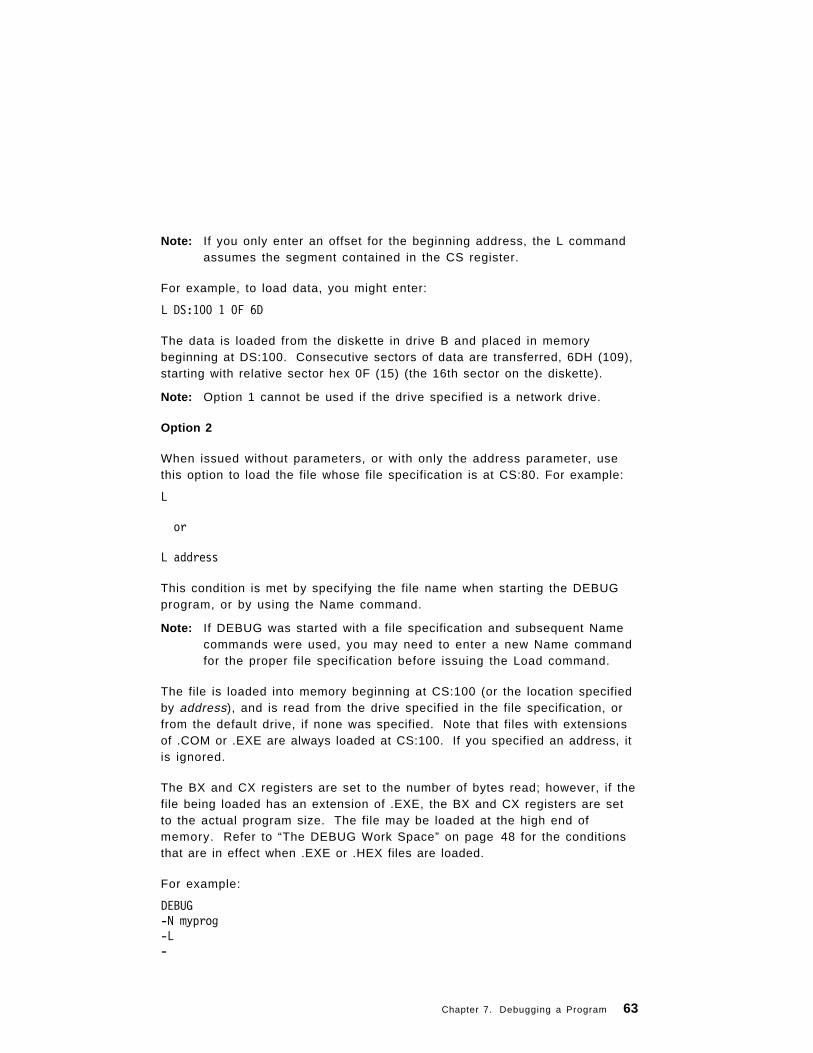
Note: If you only enter an offset for the beginning address, the L commandassumes the segment contained in the CS register.
For example, to load data, you might enter:
L DS:100 1 0F 6D
The data is loaded from the diskette in drive B and placed in memorybeginning at DS:100. Consecutive sectors of data are transferred, 6DH (109),starting with relative sector hex 0F (15) (the 16th sector on the diskette).
Note: Option 1 cannot be used if the drive specified is a network drive.
Option 2
When issued without parameters, or with only the address parameter, usethis option to load the file whose file specification is at CS:80. For example:
L
or
L address
This condition is met by specifying the file name when starting the DEBUGprogram, or by using the Name command.
Note: If DEBUG was started with a file specification and subsequent Namecommands were used, you may need to enter a new Name commandfor the proper file specification before issuing the Load command.
The file is loaded into memory beginning at CS:100 (or the location specifiedby address), and is read from the drive specified in the file specification, orfrom the default drive, if none was specified. Note that files with extensionsof .COM or .EXE are always loaded at CS:100. If you specified an address, itis ignored.
The BX and CX registers are set to the number of bytes read; however, if thefile being loaded has an extension of .EXE, the BX and CX registers are setto the actual program size. The file may be loaded at the high end ofmemory. Refer to “The DEBUG Work Space” on page 48 for the conditionsthat are in effect when .EXE or .HEX files are loaded.
For example:
DEBUG-N myprog-L-
Chapter 7. Debugging a Program 63

The file named myprog is loaded from the default directory and placed inmemory beginning at location CS:0100.
M (Move) Command
PurposeMoves the contents of the memory locations specified by range to thelocations beginning at the address specified.
FormatM range address
Parametersrange Either of these two formats:
• An address followed by an offset, such as CS:100 110.• An address followed by L value, where value is the number
of hexadecimal bytes to be processed. For example, CS:100L 10.
The limit for range is hexadecimal 10000 or decimal 64KB. Tospecify a range of 64KB within 4 hexadecimal characters, enter0000 or 0 for value.
address Any of the following formats:
• A segment register plus an offset, such as CS:0100.• A segment address plus an offset, such as 4BA:0100.• An offset only, such as 100. In this case, the default
segment is used.
CommentsOverlapping moves are always performed without loss of data during thetransfer. (The source and destination areas share some of the samememory locations.)
The data in the source area remains unchanged unless overwritten by themove.
64 PC DOS 7

Notes:
1. If you enter only an offset for the beginning address of the range, the Mcommand assumes the segment contained in the DS register. If youspecify an ending address for the range, enter it with only an offsetvalue.
2. If you enter only an offset for the address of the destination area, the Mcommand assumes the segment contained in the DS register.
ExamplesM CS:100 L10 500
The 17 bytes of data from CS:100 through CS:110 are moved to the area ofmemory beginning at DS:500.
N (Name) Command
Purpose• Formats file control blocks for the first two file specifications, at CS:5C
and CS:6C. (Starting DEBUG with a file specification also formats a filecontrol block at CS:5C.)
The file control blocks are set up for the Load and Write commands andto supply required file names for the program being debugged.
• All file specifications and other parameters, including delimiters, areplaced exactly as entered in a parameter save area at CS:81, with CS:80containing the number of characters entered. Register AX is set toindicate the validity of the drive specifiers entered with the first two filespecifications.
FormatN [d:] [path ]filename [.ext]
CommentsIf you start the DEBUG program without a file specification, you must use theName command before a file can be loaded with the L command.
Chapter 7. Debugging a Program 65

ExamplesDEBUG-N myprog-L-
To define file specifications or other parameters required by the programbeing debugged, enter:
DEBUG myprog-N file1 file2-
In this example, DEBUG loads the file myprog at CS:100, and leaves the filecontrol block at CS:5C formatted with the same file specification. Then, theName command formats file control blocks for file1 and file2 at CS:5C andCS:6C, respectively. The file control block for myprog is overwritten. Theparameter area at CS:81 contains all characters entered after the N,including all delimiters, and CS:80 contains the count of those characters(hex 0C).
O (Output) Command
PurposeSends the byte to the specified output port.
FormatO portaddress byte
Parametersportaddress A 1− 4 character hexadecimal value specifying an 8- or 16-bit
port address.
ExamplesTo send the byte value 4F to output port 2F8, enter:
O 2F8 4F
66 PC DOS 7

P (Proceed) Command
PurposeCauses the execution of a subroutine call, a loop instruction, an interrupt, ora repeat string instruction to stop at the next instruction.
FormatP[= a d d r e s s ] [value ]
Parametersaddress Any of the following formats:
• A segment register plus an offset, such as CS:0100.• A segment address plus an offset, such as 4BA:0100.• An offset only, such as 100. In this case, the default
segment is used.
value A 1− 4 character hexadecimal value, specifying the number ofinstructions to execute.
CommentsWhen at a subroutine call, a loop instruction, an interrupt, or a repeat stringinstruction, issue the Proceed command to execute the instruction (performthe entire function), and return control at the next instruction. The Proceedcommand has the same syntax as the Trace command. Specifying P0 is thesame as specifying T0.
ExamplesIf the following instructions are executed:
0100 CALL 10000103 JC 2000...1000 XOR AX,AX...1XXX RET
And if CS:IP was pointing to the CALL 1000 instruction, typing P causes theexecution of the subroutine and returns control to DEBUG at the JCinstruction.
Chapter 7. Debugging a Program 67

Q (Quit) Command
PurposeEnds the DEBUG program.
FormatQ
CommentsThe file that you are working on in memory is not saved by the Quitcommand. You must use the Write command to save the file.
DEBUG returns to the command processor which then issues the normalcommand prompt.
Examples-QA>
R (Register) Command
PurposeThe Register command has the following three functions:
• Displays the hexadecimal contents of a single register with the option ofchanging those contents
• Displays the hexadecimal contents of all the registers, plus thealphabetic flag settings, and the next instruction to be executed
• Displays the eight 2-letter alphabetic flag settings with the option ofchanging any or all of them.
FormatR [registername ]
68 PC DOS 7

Parametersregistername The valid names are:
AX SP CS IP BX BP DS F CX SI ES DX DI SS
IP refers to the instruction pointer, and F refers to the flagsregister.
CommentsWhen the DEBUG program starts, the registers and flags are set to certainvalues for the program being debugged. (Refer to “The DEBUG Work Space”on page 48.)
Display a Single Register
To display the contents of a single register, enter the register name:
R AX
The system might respond with:
AX F1E4:
Now you can take one of two actions: press the Enter key to leave thecontents unchanged, or change the contents of the AX register by entering a1-4 character hexadecimal value, such as hex FFF.
AX F1E4:FFF
Now, pressing the Enter key changes the contents of the AX register to hex0FFF.
Display All Registers and Flags
To display the contents of all registers and flags and the next instruction tobe executed, type:
R
The system responds:
AX=0E00 BX=00FF CX=0007 DX=01FF SP=039D BP=0000 SI=005C DI=0000DS=3D5B ES=3D5B SS=3D5B CS=3D5B IP=011A NV UP EI PL NZ NA PO NC3D5B:011A CD21 INT 21
Chapter 7. Debugging a Program 69

The first four lines display the hexadecimal contents of the registers and theeight alphabetic flag settings. The last line indicates the location of the nextinstruction to be executed and its hexadecimal and unassembled formats.This is the instruction pointed to by CS:IP.
A system with an 80-column display shows:
1st line - 8 registers2nd line - 5 registers and 8 flag settings3rd line - next instruction information
A system with a 40-column display shows:
1st line - 4 registers2nd line - 4 registers3rd line - 4 registers4th line - 1 register and 8 flag settings5th line - next instruction information
Display All FlagsThere are eight flags, each with two-letter codes to indicate either a setcondition or a clear condition. The flags appear in displays in the ordershown in the following table:
To display all flags, enter:
R F
If all the flags are in a set condition, the response is:
OV DN EI NG ZR AC PE CY -
Now you can either press the Enter key to leave the settings unchanged orchange any or all of the settings.
Flag Name Set Clear
Overf low (yes/no) OV NV
Direction (decrease/increase) DN UP
Interrupt (enable/disable) EI DI
Sign (negative/posit ive) NG PL
Zero (yes/no) ZR NZ
Auxil iary carry (yes/no) AC NA
Pari ty (even/odd) PE PO
Carry (yes/no) CY NC
70 PC DOS 7

To change a flag, just enter its opposite code. The opposite codes can beentered in any order with or without intervening spaces. For example, tochange the first, third, fifth, and seventh flags, enter:
OV DN EI NG ZR AC PE CY - PONZDINV
The changes in this example are entered in reverse order.
Press the Enter key and the flags are modified as specified, the promptappears, and you can enter the next command.
If you want to see if the new codes are in effect, enter:
R F
The response is:
NV DN DI NG NZ AC PO CY -
The first, third, fifth, and seventh flags are changed as requested. Thesecond, fourth, sixth, and eighth flags are unchanged. A single flag can bechanged only once for each R F command.
S (Search) Command
PurposeSearches the range for the character(s) in the list.
FormatS range list
range Either of these two formats:
• An address followed by an offset, such as CS:100 110.• An address followed by L value, where value is the number
of hexadecimal bytes to be processed. For example, CS:100L 10.
The limit for range is hexadecimal 10000 or decimal 64KB. Tospecify a range of 64KB within 4 hexadecimal characters, enter0000 or 0 for value.
list A string of byte values. If you include a character string,enclose the characters in single or double quotation marks. Tospecify a quotation mark as a character within the string when itis also used to delimit the string, type it twice.
Chapter 7. Debugging a Program 71

″These ″″quotes″″ are correct.″′ This one′ ′ s okay, too.′
CommentsAll matches are indicated by displaying the addresses where matches arefound.
A display of the prompt without an address means that no match was found.
Note: If you enter only an offset for the starting address of the range, the Scommand assumes the segment contained in the DS register.
ExamplesIf you want to search the range of addresses from CS:100 through CS:110 forhex 41, type:
S CS:100 110 41
If two matches are found the response might be:
04BA:010404BA:010D
If you want to search the same range of addresses for a match with the4-byte list (41 ″AB″ E), enter:
S CS:100 L 11 41 ″AB″ E
The starting addresses of all matches are listed. If no match is found, noaddress is displayed.
T (Trace) Command
PurposeExecutes one or more instructions starting with the instruction at CS:IP, or at= address, if it is specified. The = must be entered. One instruction is
assumed, but you can specify more than one with value. This commanddisplays the contents of all registers and flags after each instructionexecutes. For a description of the display format, refer to the Registercommand.
72 PC DOS 7

FormatT [ = address] [value]
Parametersaddress Any of the following formats:
• A segment register plus an offset, such as CS:0100.• A segment address plus an offset, such as 4BA:0100.• An offset only, such as 100. In this case, the default
segment is used.
value A 1− 4 character hexadecimal value, specifying the number ofinstructions to execute.
CommentsThe display caused by the Trace command continues until value instructionsare executed. Therefore, when tracing multiple instructions, remember youcan suspend the scrolling at any time by pressing the Ctrl and the NumLockkeys together, or the Pause key. Resume scrolling by entering any othercharacter.
Notes:
1. The Trace command disables all hardware interrupts before executingthe user instruction, and then re-enables the interrupts when the trapinterrupt occurs following the execution of the instruction.
2. TRACE should not be used with any steps that change the contents of the8259 interrupt mask (ports 20 and 21).
3. If you trace an INT3 instruction, the breakpoint is set at the INT3 location.
ExamplesT
If the IP register contains 011A, and that location contains B40E (MOVAH,0EH), this may be displayed:
AX=0E00 BX=00FF CX=0007 DX=01FF SP=039D BP=0000 SI=005C DI=0000DS=3D5B ES=3D5B SS=3D5B CS=3D5B IP=011C NV UP EI PL NZ NA PO NC3D5B:011C CD21 INT 21
This displays the results after the instruction at 011A is executed, andindicates the next instruction to be executed is the INT 21 at location04BA:011C.
T 10
Chapter 7. Debugging a Program 73

Sixteen instructions are executed (starting at CS:IP). The contents of allregisters and flags are displayed after each instruction. The display stopsafter the 16th instruction has been executed. Displays may scroll off thescreen unless you suspend the display by simultaneously pressing the Ctrland NumLock keys, or the Pause key.
U (Unassemble) Command
PurposeUnassembles instructions (that is, translates the contents of memory intoassembler-like statements) and displays their addresses and hexadecimalvalues, together with assembler-like statements. For example, a displaymight look like this:
04BA:0100 206472 AND [SI+72],AH04BA:0103 FC CLD04BA:0104 7665 JBE 016B
FormatU [address]
or
U [range ]
Parametersaddress Any of the following formats:
• A segment register plus an offset, such as CS:0100.• A segment address plus an offset, such as 4BA:0100.• An offset only, such as 100. In this case, the default
segment is used.
range Either of these two formats:
• An address followed by an offset, such as CS:100 110.• An address followed by L value, where value is the number
of hexadecimal bytes to be processed. For example, CS:100L 10.
The limit for range is hexadecimal 10000 or decimal 64KB. Tospecify a range of 64KB within 4 hexadecimal characters, enter0000 or 0 for value.
74 PC DOS 7

CommentsThe number of bytes to be unassembled depends on your system displayformat (40 or 80 columns), and which option you use with the Unassemblecommand.
Notes:
1. In all cases, the number of bytes unassembled and displayed may beslightly more than either the amount requested or the default amount.This happens because the length of the instructions vary. Therefore,unassembling the last instruction may result in more bytes thanexpected.
2. Make sure that the address parameters refer to locations containing valid8086/8088 instruction codes. If you specify an address that does notcontain the first byte of a valid instruction, the display will be incorrect.
3. If you enter only an offset for the starting address, the U commandassumes the segment contained in the CS register.
The Unassemble command has the following two format options:
Option 1
Use this option to either unassemble instructions without specifying anaddress, or to unassemble instructions beginning with a specified address.For example:
U
or
U address
Sixteen bytes are unassembled with a 40-column display. Thirty-two bytesare unassembled in 80-column mode.
Instructions are unassembled beginning with the specified address.
If you do not specify an address, the U command assumes the startingaddress is the location following the last instruction unassembled by aprevious U command. Thus, it is possible to unassemble consecutivelocations, producing continuous unassembled displays, by enteringconsecutive U commands without parameters.
If no previous U command is entered, the location is offset hex 0100 into thesegment originally initialized in the segment registers by DEBUG.
Chapter 7. Debugging a Program 75
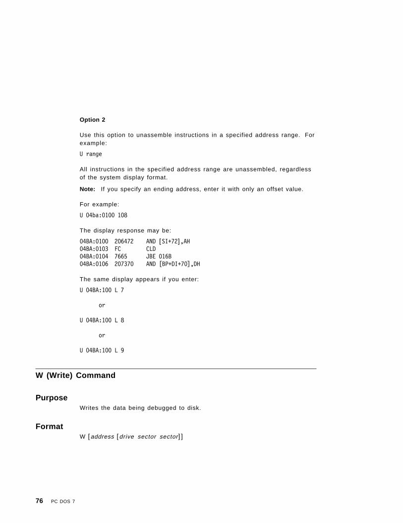
Option 2
Use this option to unassemble instructions in a specified address range. Forexample:
U range
All instructions in the specified address range are unassembled, regardlessof the system display format.
Note: If you specify an ending address, enter it with only an offset value.
For example:
U 04ba:0100 108
The display response may be:
04BA:0100 206472 AND [SI+72],AH04BA:0103 FC CLD04BA:0104 7665 JBE 016B04BA:0106 207370 AND [BP+DI+70],DH
The same display appears if you enter:
U 04BA:100 L 7
or
U 04BA:100 L 8
or
U 04BA:100 L 9
W (Write) Command
PurposeWrites the data being debugged to disk.
FormatW [address [drive sector sector]]
76 PC DOS 7

Parametersaddress Any of the following formats:
• A segment register plus an offset, such as CS:0100.• A segment address plus an offset, such as 4BA:0100.• An offset only, such as 100. In this case, the default
segment is used.
drive A decimal number that indicates a particular drive. Forexample, drive A is 0, drive B is 1, and so on.
sector 1− 3 character hexadecimal values that specify the startingrelative sector number and the number of sectors to be loadedor written.
Note: Relative sector numbers are obtained by counting thesectors on the disk surface. The first sector on the diskis at track 0, sector 1, head 0, and is relative sector 0.The numbering continues for each sector on that trackand head, then continues with the first sector on the nexthead of the same track. When all sectors on all heads ofthe track have been counted, numbering continues withthe first sector on head 0 of the next track.
CommentsNo more than hex 80 sectors can be written with a single Write command. Asector contains 512 bytes.
DEBUG displays a message if a disk write error occurs. You can retry thewrite operation by pressing the F3 key to re-display the Write command, thenpress the Enter key.
The Write command has two format options.
Option 1
Use this option to write data to disk beginning at a specified address. Forexample:
W address drive sector sector
The data beginning at the specified address is written to the disk in theindicated drive. The data is written starting at the specified starting relativesector (first sector) and continues until the requested number of sectors arefilled (second sector).
Chapter 7. Debugging a Program 77

Notes:
1. Be extremely careful when you write data to absolute sectors because anerroneous sector specification destroys whatever was on the disk at thatlocation.
2. If only an offset is entered for the beginning address, the W commandassumes the segment is contained in the CS register.
3. Remember, the starting sector and the sector count are both specified inhexadecimal.
4. Option 1 cannot be used if the specified drive is a network drive.
For example:
W 1FD 1 100 A
The data beginning at CS:01FD is written to the diskette in drive B, starting atrelative sector hex 100 (256) and continuing for hex 0A (10) sectors.
Option 2
This option permits you to use the WRITE command without specifyingparameters or specifying only the address parameter. For example:
W
or
W address
When issued as shown above, the Write command writes the file (whose filespecification is at CS:80) to disk.
This condition is met by specifying the file when starting the DEBUGprogram, or by using the Name command.
Note: If DEBUG was started with a file specification and subsequent Namecommands were used, you may need to enter a new Name commandfor the proper file specification before issuing the Write command.
In addition, the BX and CX registers must be set to the number of bytes to bewritten. They may have been set properly by the DEBUG or Loadcommands, but were changed by a Go or Trace command. You must becertain the BX and CX registers contain the correct values.
The file beginning at CS:100, or at the location specified by address, iswritten to the diskette in the drive included in the file specification or thedefault drive if no drive was specified.
78 PC DOS 7

The debugged file is written over the original file that was loaded intomemory, or into a new file if the file name in the FCB didn′ t previously exist.
Note: An error message is issued if you try to write a file with an extensionof .EXE or .HEX. These files are written in a specific format thatDEBUG cannot support.
If you find it necessary to modify a file with an extension of .EXE or .HEX, andthe exact locations to be modified are known, use the following procedure:
1. RENAME the file to an extension other than .EXE or .HEX.
2. Load the file into memory using the DEBUG or Load command.
3. Modify the file as needed in memory, but do not try to execute it with theGo or Trace commands. Unpredictable results would occur.
4. Write the file back using the Write command.
5. RENAME the file to its correct name.
XA (EMS Allocate) Command
PurposeAllocates a specified number of expanded memory pages to a handle.
FormatXA count
CommentsThe count indicates the number of 16K pages to allocate. If the amount ofexpanded memory identified by count is available, a message is displayed,indicating that a handle has been created. The XS (EMS Status) commandcan be used to display the number of expanded memory pages that areavailable.
ExamplesTo allocate two EMS pages, enter:
XA 2
If two pages of memory are available, a message like this is displayed:
Handle created = 000E
Chapter 7. Debugging a Program 79

XD (EMS Deallocate) Command
PurposeDeallocates a handle.
FormatXD handle
CommentsThe handle identifies the number of the handle to be deallocated. If thenumber is valid, a message is displayed, indicating the handle has beendeallocated. The XS (EMS Status) command can be used to display thehandles currently being used.
ExamplesTo deallocate a handle when you have only one allocated, you can enter:
XD 000E
If the handle deallocation is successful, you receive a message like this:
Handle 000E deallocated.
XM (EMS Map) Command
PurposeMaps an EMS logical page to an EMS physical page from an EMS handle.
FormatXM lpage ppage handle
CommentsThe lpage specifies the number of the handle′s logical page that is to bemapped. The ppage is the number of the physical page to be mapped to.The handle is the EMS allocated label used to reference a group of logicalpages. If syntax items are valid, a message is displayed indicating that thelogical page has been mapped to the physical page.
80 PC DOS 7
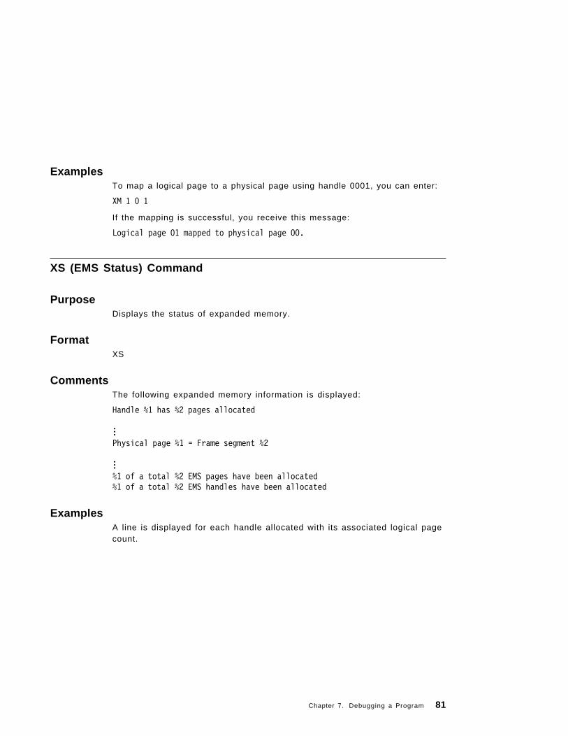
ExamplesTo map a logical page to a physical page using handle 0001, you can enter:
XM 1 0 1
If the mapping is successful, you receive this message:
Logical page 01 mapped to physical page 00.
XS (EMS Status) Command
PurposeDisplays the status of expanded memory.
FormatXS
CommentsThe following expanded memory information is displayed:
Handle %1 has %2 pages allocated
...Physical page %1 = Frame segment %2
...%1 of a total %2 EMS pages have been allocated%1 of a total %2 EMS handles have been allocated
ExamplesA line is displayed for each handle allocated with its associated logical pagecount.
Chapter 7. Debugging a Program 81

DEBUG Error MessagesThe following error messages are produced by the DEBUG utility:
Access denied The result of attempting to Write (W) toa read-only file.
Disk error reading drive %1 An invalid parameter was entered onthe Load (L) command or an erroroccurred on issuing the Load (L)command.
Disk error writing drive %1 An invalid parameter was entered onthe Write (W) command or an erroroccurred on issuing the Write (W)command.
EMS hardware/software failure The result of an EMS command. Tellsthe user EMS is not functioningproperly.
EMS not installed The result of an EMS command. Tellsuser EMS is not installed.
∧ Error Points to the offending operand in anerror condition.
Error in EXE or HEX file The EXE or HEX file are in error.
EXE and HEX files cannot be written A file in EXE or HEX format cannot bewritten to a disk.
EXEC failure The execution of the requested filefailed.
File creation error The result of attempting to Write (W) toa system or hidden file.
File not found Issued from the Load (L) commandwhen a file is not found for loading.
Free pages exceeded The result of an EMS command. Tellsthe user that the request has exceededthe amount of free EMS pagesavailable.
Handle not found The result of an EMS command. Tellsthe user an EMS handle was not found.
Incorrect DOS version Incorrect version of DEBUG for the DOSversion running.
82 PC DOS 7

Insufficient memory Not enough memory to Load (L) thespecified file.
Insufficient space on disk Out of disk space for a Write (W)command.
Invalid drive specification The drive referenced by the Name (N)and Load (L) command is invalid; thatis, it does not exist.
Logical Page out of range The result of an EMS command. Tellsthe user that the logical page requestedis not in the range of possible pages.
Missing or invalid EMS parameter The result of an EMS command. Tellsthe user a missing or invalid parameterwas entered.
No free handles The result of an EMS command. Tellsthe user that there are no more EMShandles available for allocation.
Parameter error The result of an EMS command. Tellsthe user that an EMS parameter is inerror.
Physical Page out of range The result of an EMS command. Tellsthe user that the physical pagerequested is not in the range ofpossible pages.
Program terminated normally An Interrupt 20H has been encountered,signalling program termination.
Total pages exceeded The result of an EMS command. Tellsthe user that the total EMS pages havebeen exceeded.
Write (W) error, no destination defined Attempt to Write (W) to a file that hasnot yet been Named (N).
Write protect error writing drive %1 A Write (W) to a write-protected diskcaused an error.
Writing %1 bytes Reports the number of bytes written toa file when the Write (W) command isissued.
Chapter 7. Debugging a Program 83

84 PC DOS 7

Chapter 8. Writing an Installable Device Driver
This chapter provides guide and system architecture information to supportsuccessful creation of an installable device driver.
Types of Device DriversA device driver is a memory image file or an .EXE file that contains the codeneeded to implement a device. DOS allows two types of device drivers to beinstalled:
• Character device drivers• Block device drivers.
Character Device DriversCharacter device drivers perform character I/O in a serial manner and havenames such as CON, AUX, CLOCK$. You can open handles or FCBs toperform input and output to character devices. Because character devicedrivers have only one name, they support only one device.
Block Device DriversBlock device drivers are the hard disk or diskette drives on the system.They perform random I/O in pieces called blocks, which are usually thephysical sector size of the disk. Block devices are not named as characterdevices are and you cannot open them. Instead they are mapped using thedrive letters such as A, B, and C.
A single block device driver can be responsible for one or more disk ordiskette drives. For example, the first block device driver in the device chainmay define four units such as A, B, C, and D. The second device driver maydefine three units: E, F, and G. The limit is 26 devices with the letters Athrough Z assigned to drives. The position of the driver in the chaindetermines the way in which the drive units and drive letters correspond.
How PC DOS 7 Installs Device DriversPC DOS 7 installs device drivers at startup time by reading and processingthe DEVICE command in CONFIG.SYS. For example, if you have written adevice driver called DRIVER1, include the following command inCONFIG.SYS:
device=driver1
Copyright IBM Corp. 1995 85

In PC DOS 7 a new command DYNALOAD has been added to allow you todynamically load device drivers from the command line. The following is anexample of this:
C:>DYNALOAD ANSI.SYS
The PC DOS 7 device interface links device drivers together in a chain,permitting you to add device drivers for optional devices.
Each device must be initialized. The device driver′s initialization interruptroutine is called once when the device is installed. The initialization routinereturns the location in memory of the ending address of the device driver.After setting the ending address field, a character device driver sets thestatus word and returns.
PC DOS 7 processes installed character device drivers before handlingdefault devices. To have PC DOS 7 install a new CON device (for example,in the device driver header′s Name/Unit field) name the device CON and setthe standard input device and standard output device bits in the attributefield. Because PC DOS 7 installs drivers anywhere in memory, care must betaken in any references to locations not in the segment. Your driver will notalways be loaded at the same memory location each time.
Block devices are installed in the same manner as character devices, above.Block devices return additional information such as the number of units.This number identifies the devices′ logical names. For example, if thecurrent maximum logical device letter is F at the time of the install call, andthe block device driver initialization routine returns three logical units, thelogical names of the devices are G, H, and I. The mapping is determined bythe position of the driver in the device list and the number of units associatedwith the device. The number of units returned by INIT overrides the value inthe name/unit field of the device header.
A block device also returns a pointer to a BIOS parameter block (BPB) array.This is a pointer to an array of n word pointers, where n is the number ofunits defined. If all the units are the same, the array is able to point to thesame BIOS parameter block, thus saving space. The array must beprotected below the ending address pointer set by the return.
The BPB contains information pertinent to the devices such as the sectorsize and the number of sectors per allocation unit. The sector size in theBPB cannot be greater than the maximum allowed size set by PC DOS 7initialization.
A block device returns the media descriptor byte passed to devices to reportwhich parameters PC DOS 7 is using for a particular drive unit.
86 PC DOS 7

The Basic Parts of a Device DriverA device driver is a memory image file or an .EXE file containing the codeneeded to implement a device. All PC DOS 7 installable device drivers havethese things in common:
• A device driver header, which identifies the device to PC DOS 7 anddefines the strategy and interrupt entry points. Since a device driver issimply loaded and does not use a program segment prefix, the deviceheader must be located at physical location 0 of the device driver (ORG 0or no ORG statement).
• A strategy routine, which saves a pointer to the Request Header.• The interrupt routines, which perform the requested operation.
The Device Driver HeaderA device driver requires a device header containing the following:
Field Length
Pointer to next device header DWORD
Attribute WORD
Pointer to device strategy routine WORD
Pointer to device interrupt routine WORD
Name/unit f ield 8 BYTES
Pointer to Next Device HeaderThe device driver header is a pointer to the device header of the next devicedriver. It is a doubleword field set by PC DOS 7 at the time the device driveris loaded. The first word is an offset and the second word is the segment.
If you are loading only one device driver, set the device header field to -1before loading the device. If you are loading more than one device driver,set the first word of the device header field to the offset of the next devicedriver ′s header. Set the device header field of the last device driver to -1.
Attribute FieldThe attribute field identifies the device to PC DOS 7.
Chapter 8. Writing an Installable Device Driver 87

Bit 15Bit 15 identifies whether the device is a block device or a character device.If bit 15 is set to 0, this indicates a block device. Setting bit 15 to 1 indicatesa character device. Note how the setting of bit 15 affects the interpretation ofthe setting of the bits below.
Bit 14Bit 14, for both character and block devices, tells PC DOS 7 whether thedevice driver can handle control strings through IOCtl 44H, AL=2 throughA L = 5 . Set bit 14 to 1 if control strings can be processed. IOCtl subfunctionspermit the device driver to interpret the information passed to it, such assetting a baud rate or changing form lengths, without performing standardreads and writes. Set bit 14 to 0 if control strings cannot be processed. PCDOS 7 will return an error if an IOCtl is issued to send or receive controlstrings and bit 14 is set to 0.
Bit 13Bit 13 is used for both block and character devices. For block devices, set bit13 to 0 if the media is an IBM format. Set bit 13 to 1 if the media is anon-IBM format. For character devices, set bit 13 to 0 if the driver supportsoutput-until-busy. Set bit 13 to 1 if it does not.
With the support of output-until-busy, the device driver will send charactersto the device if the device is ready. If the device is not ready, the devicedriver will immediately return an error.
Bit 12Bit 12 is reserved.
Bit 11Set bit 11 if the device driver can handle removable media. This bit is calledthe open/close removable media bit.
Bits 10 − 8Bits 10 through 8 are reserved.
Bit 7For DOS 5.0 and later versions, set bit 7 to 1 to indicate that a device driversupports Query IOCtl. If this bit is set, the driver can be called with function19H (with a standard Generic IOCtl request packet).
88 PC DOS 7

Bit 6Bit 6 is the generic IOCtl bit for both character and block device drivers. Ifthis bit is set to 1, the device driver supports generic IOCtl function calls.Setting this bit to 1 also indicates support of the Get/Set Logical Drivefunction for a block device driver.
Bits 5 and 4Bits 5 and 4 are reserved.
Bit 3Set bit 3 to 1 if the character device is a clock device; set bit 3 to 0 if it is not.
Bit 2Set bit 2 to 1 if the character device is the NUL device; set bit 2 to 0 if it isnot. Setting the bit tells PC DOS 7 whether the NUL device is being used.The NUL device cannot be reassigned.
Bit 1If bit 15 is set to 1 for a character device, set bit 1 to 1 to indicate that thecharacter device is the current standard output device. If bit 15 is set to 0 fora block device, set bit 1 to 1 to indicate support for 32-bit sector numbers;otherwise, 16-bit sector number support is assumed.
Bit 0Set bit 0 to 1 if the character device is the current standard input device; setbit 0 to 0 if it is not the current standard input device.
Pointers to Strategy and Interrupt RoutinesWhen PC DOS 7 passes a request to a device driver, it calls the device drivertwice. These two fields point to the first and second entry points: thestrategy routine and the interrupt routine. The fields are word values, sothey must be in the same segment as the device header.
Name/Unit FieldThese 8-byte fields identify a character device by name or a block device byunit. A character device name is left-justified followed by spaces, ifnecessary. For block devices, although PC DOS 7 automatically fills in thisfield with the value of number of units returned by INIT call, you may chooseto place the number of units in the first place.
Chapter 8. Writing an Installable Device Driver 89

The Strategy RoutinePC DOS 7 calls a device driver at the strategy routine at first, passing in arequest packet the information describing what PC DOS 7 wants the devicedriver to do.
The strategy routine does not perform the request but queues the request orsaves a pointer to the request packet.
The Interrupt RoutinePC DOS 7 calls the device driver′s interrupt routine with no parametersimmediately after the strategy routine returns. An interrupt routine ′s functionis to perform the operation based on the queued request, process any datain the request packet, and set up information being returned to PC DOS 7.
It is the responsibility of the device driver to preserve the system state. Forexample, the device driver must save all registers on entry and restore themon exit. The stack maintained by PC DOS 7 is used to save all registers. Ifmore stack space is needed, it is the device driver′s responsibility to allocateand maintain an additional stack.
All calls to device drivers are FAR calls. FAR returns should be executed toreturn to PC DOS 7.
How PC DOS 7 Passes a RequestPC DOS 7 passes a pointer in ES:BX to the request packet. The packetconsists of a request header that contains information common to allrequests, followed by data pertinent to the request being made.
The structure of the request header is shown below.
Field Length
Length of the request header and subsequent data BYTE
Unit code for block devices only BYTE
Command code BYTE
Status WORD
Reserved 8-BYTE
Data VARIABLE
90 PC DOS 7

Length FieldThe length field identifies the length of the request header and subsequentdata in bytes.
Unit Code FieldThe unit code field identifies the requesting unit in a block device driver. If ablock device driver has three units defined, for example, the possible valuesfor the unit code field are 0, 1, or 2.
Command Code FieldThe command code identifies the request. See “Responding to Requests” onpage 92 for a list of command code values and request descriptions.
Status FieldThe status word field is zero on entry and is set by the driver interruptroutine on return.
Bit 15Bit 15 is the error bit. If bit 15 is set to 1, the low order 8 bits of the statusword (7-0) indicate the error code.
Bits 14 − 1 0Bits 14 through 10 are reserved.
Bit 9Bit 9 is the busy bit. As a response to status request call, character devicedrivers can set the busy bit to indicate whether or not a device is ready toperform input and output requests. Block device drivers can set the busy bitto indicate removable or nonremovable media. See “Character Input andOutput Status Requests” on page 101 and “Removable Media Request” onpage 103 for more information about the calls.
Bit 8Bit 8 is the done bit. If set, the operation is complete. The driver sets thedone bit to 1 when it exits.
Bits 7 − 0Bits 7 through 0 are the low order 8 bits of the status word. If bit 15 is set,bits 7 through 0 contain the error codes. The error codes and errors are:
Codes Meaning00 Write protect violation01 Unknown unit02 Device not ready
Chapter 8. Writing an Installable Device Driver 91

03 Unknown command04 CRC error05 Bad drive request structure length06 Seek error07 Unknown media08 Sector not found09 Printer out of paper0A Write fault0B Read fault0C General failure0D Reserved0E Reserved0F Invalid disk change
Responding to RequestsEach request packet that is passed to the device driver contains a commandcode value in the request header to tell the driver which function to perform.The following table contains the PC DOS 7 device interface command codevalues and the functions to be performed when these values are passed withdata. Note that some of these functions are specific to either a block deviceor a character device.
Following this table are detailed descriptions of request data structures andwhat the interrupt routines are expected to do. Some of these descriptionspertain to more than one command code.
CommandCode
RequestDescription
DeviceType
0 Initialization Both
1 Media check Block
2 Bui ld BPB Block
3 IOCtl input (called only if bit 14 of attribute is set to 1) Both
4 Input (read) Both
5 Nondestructive input no wait Character
6 Input status Character
7 Input flush Character
8 Output (write) Both
9 Output (write with verify) Block
10 (0AH) Output status Character
11 (0BH) Output flush Character
92 PC DOS 7

CommandCode
RequestDescription
DeviceType
12 (0CH) IOCtl output (called only if bit 14 of attribute is set to1)
Character
13 (0DH) Device open (called only if bit 11 of attribute is set to1)
Both
14 (0EH) Device close (called only if bit 11 of attribute is set to1)
Both
15 (0FH) Removable media (called only if bit 11 of attribute isset to 1)
Block
16 (10H) Output until busy character Both
19 (13H) Generic IOCtl Request (called only if bit 6 of attributeis set to 1)
Block
23 (17H) Get logical device (called only if bit 6 of attribute isset to 1)
Block
24 (18H) Set logical device (called only if bit 6 of attribute isset to 1)
Block
25 (19H) IOCtl Query (called only if bit 7 of attribute is set to1)
Both
Initialization RequestCommand Code = 0
The driver must do the following:
• Set the number of units (block devices only).• Set up the pointer to the BPB array (block devices only).• Perform any initialization code (to modems, printers, and others).• Set the ending address of the resident program code.• Set the status word in the request header.
To obtain information passed from CONFIG.SYS to a device driver atinitialization time, the BPB pointer field points to a buffer containing theinformation passed in CONFIG.SYS following the =. This string may end
Field Length
Request header 13 − BYTE
Number of units (not set by character devices) BYTE
Ending address of resident program code DWORD
Pointer to BPB array (not set by character devices) pointer to remainderof arguments
DWORD
Drive number BYTE
CONFIG.SYS Error Message control flag WORD
Chapter 8. Writing an Installable Device Driver 93

with either a carriage return (0DH) or a linefeed (0AH). This information isread-only. Only system calls 01H− 0 CH and 30H can be issued by theinitialization code of the driver.
The last byte parameter contains the drive letter for the first unit of a blockdriver. For example, 0=A, 1=B and so forth.
If an initialization routine determines that it cannot set up the device andwants to terminate without using any memory, use the following procedure:
• Set the number of units to 0.• Set the ending address offset to 0.• Set the ending address segment to the code segment (CS).
For DOS 5.0 support; when loading device drivers into UMBs (Upper MemoryBlocks), PC DOS 7 sets the maximum address that is available to the devicedriver in the INIT request packet. This is stored in the ending address fieldbefore the device′s INIT function is called. The value is the normalizedaddress of the top of the memory block that is allocated to the driver. This isdone before devices complete initialization so memory requirements can bechecked against the amount of space available. If there is not enough spacefor a device′s code and data requirements, they will fail to load.
Block device drivers must account for the space needed for a DiskParameter Block per unit supported. The amount of space needed for ablock device driver is:
(end address) - (number of units * DPB size)
If there are multiple device drivers in a single memory image file, the endingaddress returned by the last initialization called is the one PC DOS 7 uses.IBM recommends that all device drivers in a single memory image file returnthe same ending address.
If initialization of your device driver fails, and you want the system to displaythe Error in Config.Sys line # error message, set the CONFIG.SYS errormessage control flag to a non-zero value.
Media Check RequestCommand code = 1
Field Length
Request header 13 − BYTE
Media descriptor from PC DOS 7 BYTE
94 PC DOS 7

When the command code field is 1, PC DOS 7 calls Media Check for a driveunit and passes its current Media Descriptor byte. See “Media DescriptorByte.” Media Check returns one of the following:
• Media not changed• Media changed• Not sure• Error code.
The driver must perform the following:
• Set the status word in the request header.• Set the return byte to:
-1 for “media changed”0 for “not sure”1 for “media not changed.”
The driver uses the following method to determine how to set the return byte:
• If the media is nonremovable (a hard disk), set the return byte to 1.• If less than 2 seconds since last successful access, set the return byte to
1.• If changeline not available, set the return byte to 0.• If changeline is available but not active, set the return byte to 1.• If the media byte in the new BPB does not match the old media byte, set
the return byte to -1.• If the current volume ID matches the previous volume ID, or if the serial
number matches the previous serial number, set the return byte to 0.
Field Length
Return BYTE
A pointer to the previous volume ID (if bit 11 = 1 and disk change isreturned)
DWORD
Media Descriptor ByteCurrently the media descriptor byte has been defined for some media types.This byte should be identical to the media byte if the device has the non-IBMformat bit off. These predefined values are:
Media descriptorbyte — > 1 1 1 1 1 x x xbits — > 7 6 5 4 3 2 1 0
Chapter 8. Writing an Installable Device Driver 95
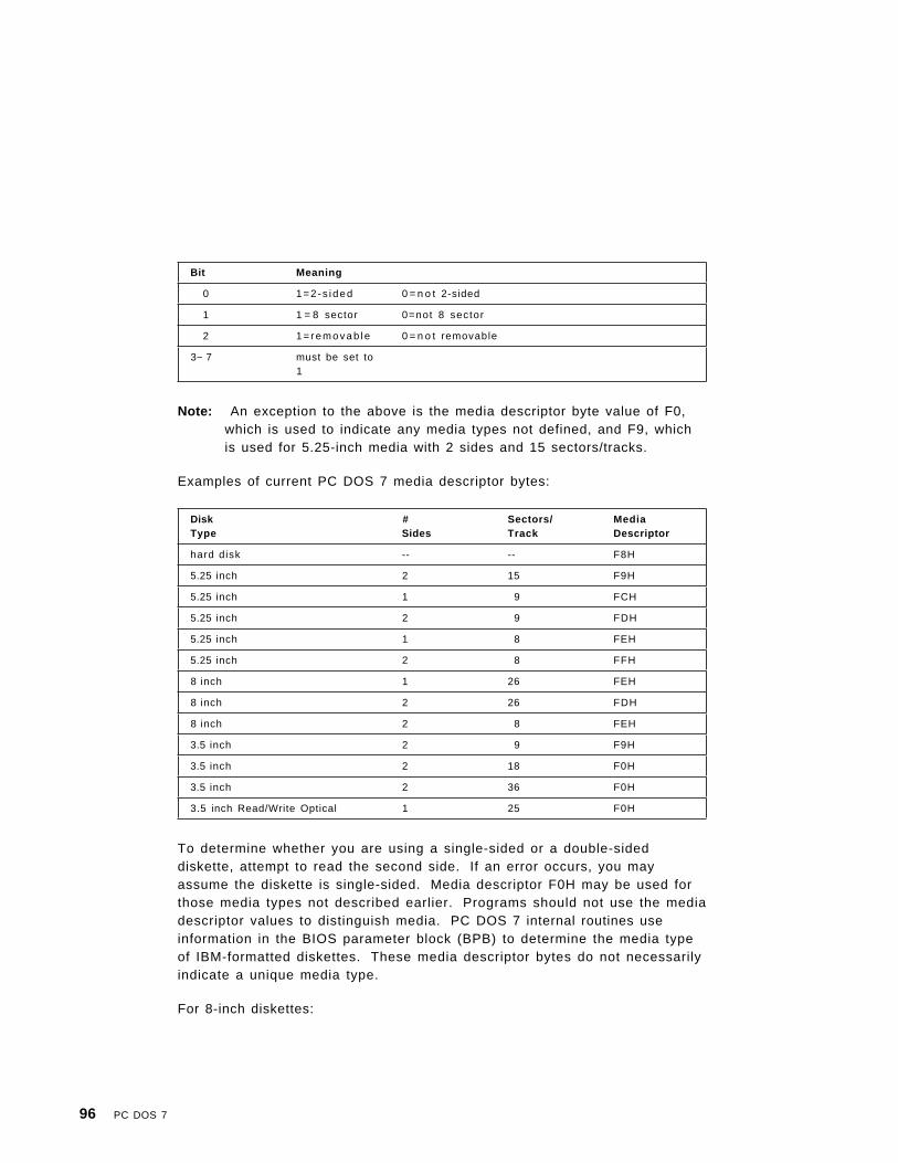
Note: An exception to the above is the media descriptor byte value of F0,which is used to indicate any media types not defined, and F9, whichis used for 5.25-inch media with 2 sides and 15 sectors/tracks.
Examples of current PC DOS 7 media descriptor bytes:
To determine whether you are using a single-sided or a double-sideddiskette, attempt to read the second side. If an error occurs, you mayassume the diskette is single-sided. Media descriptor F0H may be used forthose media types not described earlier. Programs should not use the mediadescriptor values to distinguish media. PC DOS 7 internal routines useinformation in the BIOS parameter block (BPB) to determine the media typeof IBM-formatted diskettes. These media descriptor bytes do not necessarilyindicate a unique media type.
For 8-inch diskettes:
Bit Meaning
0 1=2-s ided 0 = n o t 2-sided
1 1 = 8 sector 0=not 8 sector
2 1= removab le 0 = n o t removable
3− 7 must be set to1
DiskType
#Sides
Sectors/Track
MediaDescriptor
hard disk -- -- F8H
5.25 inch 2 15 F9H
5.25 inch 1 9 FCH
5.25 inch 2 9 FDH
5.25 inch 1 8 FEH
5.25 inch 2 8 FFH
8 inch 1 26 FEH
8 inch 2 26 FDH
8 inch 2 8 FEH
3.5 inch 2 9 F9H
3.5 inch 2 18 F0H
3.5 inch 2 36 F0H
3.5 inch Read/Write Optical 1 25 F0H
96 PC DOS 7

• FEH (IBM 3740 Format) — Single-sided, single-density, 128 bytes persector, soft-sectored, 4 sectors per allocation unit, 1 reserved sector, 2FATs, 68 directory entries, 77*26 sectors.
• FDH (IBM 3740 Format) — Double-sided, single-density, 128 bytes persector, soft-sectored, 4 sectors per allocation unit, 4 reserved sectors, 2FATs, 68 directory entries, 77*26*2 sectors.
• FEH — Double-sided, double-density, 1024 bytes per sector, soft sectored,1 sector per allocation unit, 1 reserved sector, 2 FATs, 192 directoryentries, 77*8*2 sectors.
Build BPB RequestCommand Code = 2
PC DOS 7 calls Build BPB (BIOS Parameter Block) under the following twoconditions:
• If “Media Changed” is returned• If “Not Sure” is returned, there are no used buffers. Used buffers are
buffers with changed data not yet written to the disk.
The driver must do the following:
• Set the pointer to the BPB• Set the status word in the request header.
The device driver must determine the media type that is in the unit to returnthe pointer to the BPB table. In previous versions of IBMBIO, the FAT ID bytedetermined the structure and layout of the media. The FAT ID byte has onlyeight possible values (F8 through FF), so, as new media types are invented,the available values will soon be exhausted. With the varying media layouts,PC DOS 7 needs to be aware of the location of the FATs and directoriesbefore it asks to read them.
The following paragraphs explain the method PC DOS 7 uses to determinethe media type.
Field Length
Request header 13 − BYTE
Media descriptor from PC DOS 7 BYTE
Transfer address (buffer address) DWORD
Pointer to BPB table DWORD
Chapter 8. Writing an Installable Device Driver 97

The information relating to the BPB for a particular media is kept in the bootsector for the media. The following is a summary of the format of the bootsector.
The BPB information contained in the boot sector starts with the Bytes perSector entry. The last three words are intended to help the device driveridentify the media. The number of heads is useful for supporting differentmultihead drives with the same storage capacity but a different number ofsurfaces. The number of hidden sectors is useful for supporting drivepartitioning schemes.
For drivers that support volume identification and disk change, this callcauses a new volume identification to be read from the disk. This callindicates that the disk has changed in a permissible manner.
To handle the partition that is bigger than 32MB, or one that starts beyond orcrosses the 32MB boundary, PC DOS 7 defines an extended BPB structure.Depending on the size of the media, you can use either the existing BPB orthe extended one, which contains an additional DWORD field to indicate thesize of the partition in sectors.
Bit 1 of the attribute field in the block device driver header indicates whetherthe device can process 32-bit sector numbers. Set bit 1 to indicate 32-bitsupport.
Field Length
A 2-byte short JMP instruction (EBH), followed by a NOP instruction(90H).
WORD
Product name and version 8 BYTES
Bytes per sector; must be power of 2 WORD
Sectors per allocation unit; must be power of 2 BYTE
Reserved sectors starting at logical sector 0 WORD
Number of FATs BYTE
Maximum number of root directory entries WORD
Total number of sectors in media including the boot sector, FAT areas,and directories
WORD
Media descriptor BYTE
Number of sectors occupied by a FAT WORD
Sectors per track WORD
Number of heads WORD
Number of hidden sectors WORD
98 PC DOS 7

The extended BPB is a superset of the traditional BPB structure. To achievethe maximum compatibility between this structure and that of the traditionalBPB, PC DOS 7 uses the following rules:
• If the number of hidden sectors plus the total number of sectors in themedia is greater than 64KB, use the 32-bit total number of sectors in themedia entry (DWORD).
• Otherwise, use the Total number of sectors in the media entry (WORD).
A boot record exists at the beginning of each disk partition and eachextended PC DOS 7 partition volume. PC DOS 7 automatically creates theextended boot record. The format of the extended boot record is:
Field Length
Bytes per sector WORD
Sectors per allocation unit BYTE
Reserved sectors starting at logical sector 0 WORD
Number of FATs — 0 if not a FAT system BYTE
Maximum number of root directory entries WORD
Total number of sectors in the media. This field is used to define apartition that is less than 32MB. Setting this field to 0 indicates to usethe total (32-bit) number of sectors in the media below.
WORD
Media descriptor BYTE
Number of sectors occupied by a FAT WORD
Sectors per track WORD
Number of heads WORD
Number of hidden sectors DWORD
Total (32-bit) number of sectors in the media. This field is used to definea partition that is greater than 32MB, or one that crosses the 32MBboundary.
DWORD
Field Length
A 2-byte short JMP instruction (EBH) followed by a NOP instruction(90H).
WORD
Product name and version 8 BYTES
Extended BPB 25 BYTES
Physical drive number BYTE
Reserved BYTE
Extended boot record signature BYTE
Volume serial number DWORD
Volume label 11 BYTES
Reserved 8 BYTES
Chapter 8. Writing an Installable Device Driver 99

Note: The value of Extended boot record signature is 29H. The value of thephysical drive number is always 0H or 80H.
On all requests to extended drivers with a sector number in their requestheaders, the sector number is a DWORD. The standard PC DOS 7 blockdevice drivers set the attribute bit 1 for 32-bit support.
For each call to a device driver, PC DOS 7 checks to see if the starting sectornumber passed in the request can be supported by the device driver. If thisvalue is greater than 64K for an old-style device driver, PC DOS 7 returns anunknown media (07H) device driver error.
Input and Output RequestsCommand Codes = 3, 4, 8, 9, 12 (0CH)
The PC DOS 7 Input/Output request structure can process 32-bit sectornumbers, providing support for media of more than 4 billion sectors.
The driver must do the following:
• Set the status word in the request header• Perform the requested function• Set the actual number of sectors or bytes transferred.
No error checking is performed on an IOCtl call. However, the driver mustset the return sector or byte count to the actual number of bytes transferred.
Under certain circumstances the block device driver may be asked to do aWRITE operation of 64KB that seems to be a wraparound of the transferaddress in the device driver request packet. It will only happen on WRITEsthat are within a sector size of 64KB on files that are being extended past thecurrent end of file. The block device driver is allowed to ignore the balance
Field Length
Request header 13 − BYTE
Media descriptor byte BYTE
Transfer address (buffer address) DWORD
Byte/sector count WORD
Starting sector number (If -1, use DWORD starting sector number. Thisentry has no meaning for a character device.)
WORD
For DOS 3.0 to PC DOS 7, pointer to the volume identification if errorcode 0FH is returned
DWORD
Starting 32-bit sector number. (Use this entry to the block device driverwith the attribute bit 1 set.)
DWORD
100 PC DOS 7

of the WRITE that wraps around. For example, a WRITE of 10000H bytes ofsectors with a transfer address of XXXX:1 ignores the last two bytes.
Remember that a program using PC DOS 7 function calls cannot request aninput or output operation of more than FFFFH bytes because a wrap aroundin the transfer buffer segment would occur. Bytes will be ignored that wouldhave wrapped around in the transfer segment.
If the driver returns an error code of 0FH (Invalid Disk Change), it mustprovide a DWORD pointer to an ASCIIZ string identifying the correct volumeID and the system prompts the user to reinsert the disk.
The reference count of open files on the disk maintained by OPEN andCLOSE calls allows the driver to determine when to return error 0FH. If thereare no open files (reference count=0) and the disk has been changed, theI/O is valid, and error 0FH is not returned. If there are open files (referencecount > 0) and the disk has been changed, an error 0FH situation may exist.PC DOS 7 IBMDOS.COM will request an OPEN or CLOSE function only ifSHARE is loaded.
Nondestructive Input No Wait RequestCommand Code = 5
The driver must do the following:
• Return a byte from the device.• Set the status word in the request header.
If the character device returns busy bit = 0, meaning there are characters inbuffer, the next character that would be read is returned. This character isnot removed from the input buffer (that is, nondestructive input). This callallows PC DOS 7 to look ahead one input character.
Field Length
Request header 13-BYTE
Byte read from device BYTE
Character Input and Output Status RequestsCommand Codes = 6, 10 (0AH)
Field Length
Request header 13-BYTE
Chapter 8. Writing an Installable Device Driver 101

The driver must do the following:
• Perform the requested function.• Set the busy bit.• Set the status word in the request header.
The busy bit is set differently for output and input.
Output on Character DevicesIf the busy bit is 1 on return, a write request would wait for completion of acurrent request. If the busy bit is 0, no request is waiting or running.Therefore, a write request would start immediately.
Input on Character Devices with a BufferIf the busy bit is 1 on return, a read request goes to the physical device. Ifthe busy bit is 0, characters are in the device buffer and a read returnsquickly. This also indicates that the user has typed something. PC DOS 7assumes that all character devices have a type-ahead input buffer. Devicesthat do not have this buffer should always return busy = 0 so that PC DOS 7does not loop endlessly, waiting for information to be put in a buffer thatdoes not exist.
Character Input and Output Flush RequestsCommand Codes = 7, 11 (0BH)
This call tells the driver to flush (terminate) all pending requests of which ithas knowledge. Its primary use is to flush the input queue on characterdevices.
The driver must set the status word in the Request Header upon return.
Field Length
Request header 13-BYTE
Open and Close RequestsCommand Codes = 13 (0DH), 14 (0EH)
These calls are designed to give the device information about current fileactivity on the device if bit 11 of the attribute word is set.
Field Length
Request header 13-BYTE
102 PC DOS 7

On block devices, these calls can be used to manage local buffering. Thedevice can keep a reference count. Every OPEN increases the referencecount. Every CLOSE decreases the device reference count. When thereference count is 0, there are no open files on the device. Therefore, thedevice should flush buffers inside the device to which it has written becausethe user can change the media on a removable media drive. If the mediahas been changed, reset the reference count to 0 without flushing the buffers.
These calls are more useful on character devices. The OPEN call can send adevice an initialization string. On a printer, the call can send a string to setthe font or the page size so the printer is always in a known state at the startof an I/O stream.
Similarly, the CLOSE call can send a post string, such as a form feed, at theend of an I/O stream.
Using IOCtl to set the preliminary and ending strings provides a flexiblemechanism for serial I/O device stream control.
Removable Media RequestCommand Code = 15 (0FH)
To use this call, set bit 11 of the attribute field to 1. Block devices can usethis call only by way of a subfunction of the IOCtl function call (44H).
This call is useful because it notifies a utility if it is dealing with a removableor nonremovable media drive. For example, the FORMAT utility needs toknow whether a drive is removable or nonremovable because it displaysdifferent versions of some prompts.
The information is returned in the busy bit of the status word. If the busy bitis 1, the media is nonremovable. If the busy bit is 0, the media is removable.
No error bit checking is performed. It is assumed that this call alwayssucceeds.
Field Length
Request header 13-BYTE
Chapter 8. Writing an Installable Device Driver 103

Output Until BusyCommand Code = 16 (10H)
The driver must set the status in the request header. The actual bytes aretransferred in the byte count word.
This function transfers data from the specified memory buffer to a deviceuntil it is busy. It is called only if bit 13 of the device attribute word is set inthe device header. This function is not in error if it returns with the numberof bytes transferred less than the number of bytes requested.
Field Length
Request header 13-BYTE
Transfer Address Dword
Byte Count Word
Generic IOCTL RequestCommand Code = 19 (13H)
The driver must:
• Support the functions described under Generic IOCtl request• Maintain its own track table (TrackLayout).
See Appendix C, “I/O Control for Devices (IOCtl)” on page 273 for adescription of the functions provided by generic IOCtl requests.
Field Length
Request header 13-BYTE
Major function BYTE
Minor function BYTE
Contents of SI WORD
Contents of DI WORD
Pointer to Generic IOCTL request packet DWORD
Get Logical Device RequestCommand Code = 23 (17H)
Field Length
Request header length (see note below) BYTE
Input (unit code) BYTE
104 PC DOS 7
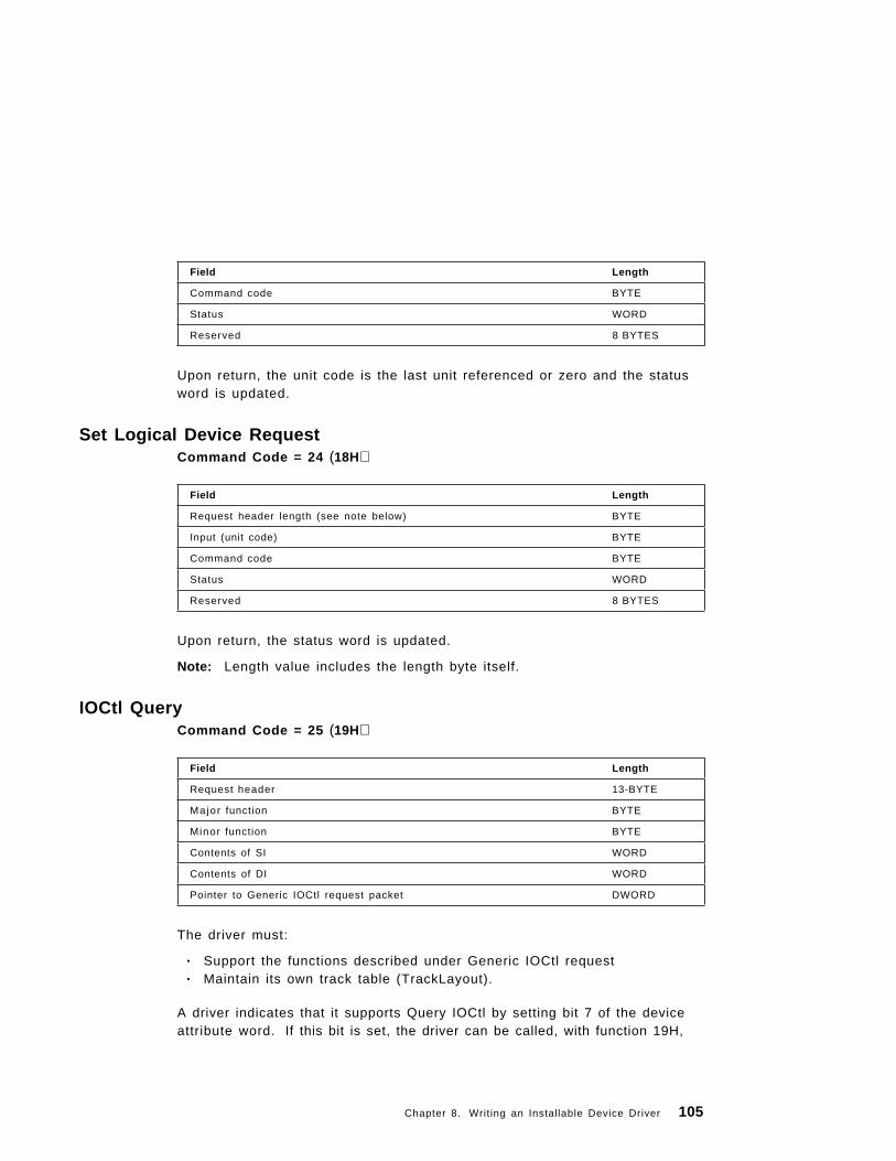
Upon return, the unit code is the last unit referenced or zero and the statusword is updated.
Field Length
Command code BYTE
Status WORD
Reserved 8 BYTES
Set Logical Device RequestCommand Code = 24 (18H)
Upon return, the status word is updated.
Note: Length value includes the length byte itself.
Field Length
Request header length (see note below) BYTE
Input (unit code) BYTE
Command code BYTE
Status WORD
Reserved 8 BYTES
IOCtl QueryCommand Code = 25 (19H)
The driver must:
• Support the functions described under Generic IOCtl request• Maintain its own track table (TrackLayout).
A driver indicates that it supports Query IOCtl by setting bit 7 of the deviceattribute word. If this bit is set, the driver can be called, with function 19H,
Field Length
Request header 13-BYTE
Major function BYTE
Minor function BYTE
Contents of SI WORD
Contents of DI WORD
Pointer to Generic IOCtl request packet DWORD
Chapter 8. Writing an Installable Device Driver 105

with a standard Generic IOCtl request packet. If it is not set, the driver willnever receive Query IOCtl calls.
The driver should check the category code and function number in therequest packet and return a no error signal if it can handle the call. If thedriver cannot handle the call, it should return the Unknown Command errorcode (error code 3). Usually, a program that wants to use Generic IOCtl callsbeyond those in DOS 3.2 will call Query IOCtlHandle or Query IOCtlDevicefirst. Then it will determine if the particular call is supported, and finally callthe actual function.
See Appendix C, “I/O Control for Devices (IOCtl)” on page 273 for adescription of the functions provided by generic IOCtl requests.
106 PC DOS 7

Appendix A. PC DOS 7 Interrupts
This chapter contains information to support use of the PC DOS 7 interrupts.
PC DOS 7 reserves interrupt types 20H to 3FH for its use. Absolute memorylocations 80H to FFH are reserved by PC DOS 7. All interrupt values are inhexadecimal.
Interrupt 20H Program TerminateIssue interrupt 20H to exit from a program. This vector transfers to the logicin PC DOS 7 to restore the terminate address, the Ctrl-Break address, andthe critical error exit address to the values they had on entry to the program.All file buffers are flushed and all handles are closed. You should close allfiles changed in length (see function call 10H and 3EH) before issuing thisinterrupt. If the changed file is not closed, its length, date, and time are notrecorded correctly in the directory.
For a program to pass a completion code or an error code when terminating,it must use either function call 4CH (Terminate a Process) or 31H (TerminateProcess and Stay Resident). These two methods are preferred over usinginterrupt 20H, and the codes returned by them can be interrogated in batchprocessing. See function call 4CH for information on the ERRORLEVELsubcommand of batch processing.
Important: Before you issue interrupt 20H, your program must ensure that theCS register contains the segment address of its program segment prefix.
Interrupt 21H Function RequestRefer to each function call issued within 21H in Appendix B, “PC DOS 7Function Calls” on page 133.
Interrupt 22H Terminate AddressControl transfers to the address at this interrupt location when the programterminates. This address is copied into the program′s Program SegmentPrefix at the time the segment is created. You should not issue thisinterrupt; the EXEC function call does this for you.
Copyright IBM Corp. 1995 107

Interrupt 23H Ctrl-Break Exit AddressIf the user presses the Ctrl and Break keys during standard input, standardoutput, standard printer, or asynchronous communications adapteroperations, an interrupt 23H is executed. If BREAK is on, the interrupt 23H ischecked on most function calls (except calls 06H and 07H). If the user-writtenCtrl-Break routine saves all registers, it may end with a return-from-interruptinstruction (IRET) to continue program execution.
If the user-written interrupt program returns with a long return, the carry flagis used to determine whether the program will be ended. If the carry flag isset, the program is ended, otherwise execution continues (as with a return byIRET).
If the user-written Ctrl-Break interrupt uses function calls 09H or 0AH, then∧C, carriage-return and linefeed are output. If execution is continued with anIRET, I/O continues from the start of the line.
When the interrupt occurs, all registers are set to the value they had whenthe original function call to PC DOS 7 was made. There are no restrictionson what the Ctrl-Break handler is allowed to do, including PC DOS 7 functioncalls, as long as the registers are unchanged if IRET is used.
When the program creates a new segment and loads in a second program itchanges the Ctrl-Break address. The termination of the second program andreturn to the first causes the Ctrl-Break address to be restored to the value ithad before execution of the second program. It is restored from the secondprogram ′s Program Segment Prefix. You should not issue this interrupt.
Interrupt 24H Critical Error Handler VectorA critical error is returned when a DOS function cannot be performed. Thiserror is frequently caused by a hardware condition, such as the printer beingout of paper, a diskette drive door open, or a diskette out of space. When acritical error occurs within PC DOS 7, control is transferred with an interrupt24H. On entry to the error handler, AH will have its bit 7=0 (high-order bit) ifthe error was a disk error (the most common occurrence), bit 7=1 if it wasnot.
BP:SI contains the address of a Device Header Control Block from whichadditional information can be retrieved. See page 112.
108 PC DOS 7

The registers are set up for a retry operation, and an error code is in thelower half of the DI register with the upper half undefined. The error codesfollow:
Error Code Meaning0 Attempt to write on write-protected diskette1 Unknown unit2 Drive not ready3 Unknown command4 Data error (CRC)5 Bad request structure length6 Seek error7 Unknown media type8 Sector not found9 Printer out of paperA Write faultB Read faultC General failure
The user stack is in effect and contains the following from top to bottom:
IP PC DOS 7 registers from issuing INT 24HCSFLAGSAX User registers at time of originalBX INT 21H requestCXDXSIDIBPDSESIP From the original interrupt 21HCS from the user to PC DOS 7FLAGS
The registers are set such that if an IRET is executed, PC DOS 7 respondsaccording to (AL) as follows:
(AL) = 0 ignore the error.= 1 retry the operation.= 2 terminate the program
through interrupt 22H.= 3 fail the system call
in progress.
Appendix A. PC DOS 7 Interrupts 109

Note: Be careful when choosing ignore as a response because this causesPC DOS 7 to believe that an operation has completed successfullywhen it may not have.
To return control from the critical error handler to a user error routine, thefollowing should occur:
Before an INT 24H occurs:
1. The user application initialization code should save the INT 24H vectorand replace the vector with one pointing to the user error routine.
When the INT 24H occurs:
2. When the user error routine receives control, it should push the flagregister onto the stack, and then execute a CALL FAR to the original INT24H vector saved in step 1.
3. PC DOS 7 gives the appropriate prompt, and waits for the user input(Abort, Retry, Fail or Ignore). After the user input, PC DOS 7 returnscontrol to the user error routine at the instruction following the CALLFAR.
4. The user error routine can now do any tasks necessary. To return to theoriginal application at the point the error occurred, the error routineneeds to execute an IRET instruction. Otherwise, the user error routineshould remove the IP, CS, and Flag registers from the stack. Control canthen be passed to the desired point.
Disk ErrorsIf it is a hard error on disk (AH bit 7=0), register AL contains the failing drivenumber (0 = drive A, and so on). AH bits 0− 2 indicate the affected diskarea and whether it was a read or write operation, as follows:
Bit 0=0 if read operation,1 if write operation
Bits 2-1 (affected disk area)0 0 PC DOS 7 area0 1 file allocation table1 0 directory1 1 data area
AH bits 3− 5 indicate which responses are valid. They are:
Bit 3=0 if FAIL is not allowed=1 if FAIL is allowed
Bit 4=0 if RETRY is not allowed=1 if RETRY is allowed
Bit 5=0 if IGNORE is not allowed
110 PC DOS 7

=1 if IGNORE is allowed
Handling of Invalid ResponsesIf IGNORE is specified (AL=0) and IGNORE is not allowed (bit 5=0), makethe response FAIL (AL=3).
If RETRY is specified (AL=1) and RETRY is not allowed (bit 4=0), make theresponse FAIL (AL=3).
If FAIL is specified (AL=3) and FAIL is not allowed (bit 3=0), make theresponse END (AL=2).
Other ErrorsIf AH bit 7=1, the error occurred on a character device, or was the result ofa bad memory image of the FAT. The device header passed in BP:SI can beexamined to determine which case exists. If the attribute byte high-order bitindicates a block device, then the error was a bad FAT. Otherwise, the erroris on a character device.
If a character device is involved, the contents of AL are unpredictable andthe error code is in DI as above.
Notes:
1. Retry five times before giving this routine control for disk errors. Whenthe errors are in the FAT or a directory, retry three times.
2. For disk errors, this exit is taken only for errors occurring during aninterrupt 21H function call. It is not used for errors during an interrupt25H or 26H.
3. This routine is entered in a disabled state.
4. All registers must be preserved.
5. This interrupt handler should refrain from using PC DOS 7 function calls.If necessary, it may use calls 01H through 0CH, 30H, and 59H. Use of anyother call destroys the PC DOS 7 stack and leaves PC DOS 7 in anunpredictable state.
6. The interrupt handler must not change the contents of the device header.
7. If the interrupt handler handles errors itself rather than returning to PCDOS 7, it should restore the application program′s registers from thestack, remove all but the last three words on the stack, then issue anIRET. This will return to the program immediately after the INT 21H thatexperienced the error. Note that if this is done, PC DOS 7 will be in anunstable state until a function call higher than 0CH is issued; therefore, itis not recommended.
Appendix A. PC DOS 7 Interrupts 111

The recommended way to end a critical error is to use FAIL and then testthe extended error code of the INT 21H.
8. IGNORE requests ( A L = 0 ) are converted to FAIL for critical errors thatoccur on FAT or DIR sectors.
9. Refer to “Responding to Errors” on page 138 and “Extended ErrorCodes” on page 138 for information on how to obtain additional errorinformation.
10. For PC DOS 7, IGNORE requests (AL=0) are converted to FAIL requestsfor certain critical errors (50− 7 9 ) .
The device header pointed to by BP:SI is formatted as follows:
To tell if the error occurred on a block or character device, look at bit 15 inthe attribute field (WORD at BP:SI +4).
If the name of the character device is desired, look at the eight bytes startingat BP:SI +10.
DWORD Pointer to next device (FFFFH if last device)
WORD Attributes:
Bit 15 = 1 i f character device= 0 i f block device
If bit 15 is 1:Bit 0 = 1 if current standard inputBit 1 = 1 if current standard outputBit 2 = 1 if current NULL deviceBit 3 = 1 if current CLOCK device
Bit 14 is the IOCtl bit
WORD pointer to device driver strategy entry point.
WORD pointer to device driver interrupt entry point.
8-BYTE character device named field for block devices. The first byte is the number ofunits.
Interrupt 25H/26H Absolute Disk Read/WriteInterrupt vectors 25H and 26H transfer control to the device driver. Theyhave been extended to allow direct access to media greater than 32MB insize. Their use of the CX register is what distinguishes them from theconventional 25H and 26H interrupts. Note that if the conventional formatparameters are used in an attempt to access media greater than 32MB, anerror code of 0207H is returned in AX.
The request for extended 25H or 26H is:
112 PC DOS 7

MOV AL,DRIVE ; Drive number to process; 0 = A; 1 = B; 2 = C . . .
MOV BX,SEG PACKET ; Parameter listMOV DS,BX ;MOV BX,OFFSET PACKET ;MOV CX,-1 ; Indicates extended formatINT 25H or 26H ; Issue request to PC DOS 7POP AX ; Discard stack wordJC ERROR ; Error code returned in AX
PACKET LABEL BYTE ; Control packetDD RBA ; RBA of first sector
; (0 origin)DW COUNT ; Number of sectors to I/ODD BUFFER ; Data buffer
On return, the original flags are still on the stack (put there by the INTinstruction). This is necessary because return information is passed back inthe current flags. Be sure to pop the stack to prevent uncontrolled growth.
Warning: If disk I/O handled by this interrupt exceeds the limit imposed bythe 64KB direct memory access boundary, unpredictable results can occur.We recommend you carefully check the sector size and the number ofsectors to be read or written to before issuing this call.
The number of sectors specified is transferred between the given drive andthe transfer address. Logical sector numbers (LSN) are obtained bynumbering each sector sequentially starting from track 0, head 0, sector 1(logical sector 0) and continuing along the same head, then to the next headuntil the last sector on the last head of the track is counted. Thus, logicalsector 1 is track 0, head 0, sector 2; logical sector 2 is track 0, head 0, sector3; and so on. Numbering continues with sector 1 on head 0 of the next track.Note that although the sectors are sequentially numbered (for example,sectors 2 and 3 on track 0 in the example above), they may not be physicallyadjacent on the disk, because of interleaving. Note that the mapping isdifferent from that used by DOS version 1.10 for double-sided diskettes.
All registers except the segment registers are destroyed by this call. If thetransfer was successful, the carry flag (CF) is 0. If the transfer was notsuccessful CF=1 and (AX) indicate the error as follows. (AL) is the PC DOS7 error code that is the same as the error code returned in the low byte of DIwhen an interrupt 24H is issued, and (AH) contains:
Appendix A. PC DOS 7 Interrupts 113

80H Attachment failed to respond40H SEEK operation failed08H Bad CRC on diskette read04H Requested sector not found03H Write attempt on write-protected diskette02H Error other than types listed above
Warning: Before issuing this interrupt to removable media, the media in thedrive must be established correctly. This can be accomplished by issuingeither an INT 21H Generic IOCTL (AH=44H), with a request to return the BPBthat BUILD BPB returns; or an INT 21H Get Current Directory (AH=47H).
Interrupt 27H Terminate but Stay ResidentThis vector is used by programs that are to remain resident whenCOMMAND.COM regains control.
PC DOS 7 function call 31H is the preferred method to cause a program toremain resident, because this allows return information to be passed. Itallows a program larger than 64KB to remain resident. After initializingitself, the program must set DX to its last address plus one, relative to theprogram ′s initial DS or ES value (the offset at which other programs can beloaded), and then execute an interrupt 27H. PC DOS 7 then considers theprogram as an extension of itself, so the program is not overlaid when otherprograms are executed. This concept is useful for loading programs such asuser-written interrupt handlers that must remain resident.
Notes:
1. This interrupt must not be used by .EXE programs that are loaded intothe high end of memory.
2. This interrupt restores the interrupt 22H, 23H, and 24H vectors in thesame manner as interrupt 20H. Therefore, it cannot be used to installpermanently resident Ctrl-Break or critical error handler routines.
3. The maximum size of memory that can be made resident by this methodis 64KB.
4. Memory can be used more efficiently if the block containing a copy of theenvironment is deallocated before terminating. This can be done byloading ES with the segment contained in 2C of the PSP, and issuingfunction call 49H (Free Allocated Memory).
5. PC DOS 7 function call 4CH allows the terminating program to pass acompletion (or error) code to PC DOS 7, which can be interpreted withinbatch processing (see function call 31H).
114 PC DOS 7

6. Terminate-but-stay-resident function calls do not automatically close files.
Interrupt 28H − 2 EH Reserved for PC DOS 7These interrupts are reserved for PC DOS 7 use.
Interrupt 2FH Multiplex InterruptInterrupt 2FH is the multiplex interrupt. A general interface is definedbetween two processes. The specific application using interrupt 2FH definesspecific functions and parameters.
Every multiplex interrupt handler is assigned a specific multiplex number.The multiplex number is specified in the AH register. The specific functionthat the handler is to perform is specified in the AL register. Otherparameters are placed in the other registers, as needed. The handlers arechained into the interrupt 2FH interrupt vector. There is no defined methodfor assigning a multiplex number to a handler. You must pick one. To avoida conflict if two applications choose the same multiplex number, themultiplex numbers used by an application should be patchable.
The multiplex numbers AH=00H through BFH are reserved for PC DOS 7.Applications should use multiplex numbers C0H through FFH.
Note: When in the chain for interrupt 2FH, if your code calls PC DOS 7 or ifyou execute with interrupts enabled, your code must be reentrant andrecursive.
Interrupt 2FH Function AH=01H PRINT.COM Function InstalledStateThe following table contains the function codes that you can specify in AL torequest the resident portion of print to perform a specific function:
FunctionCodes (in AL) Description
0 Get installed state
1 Submit fi le
2 Cancel fi le
3 Cancel all files
4 Status
5 End of status
Appendix A. PC DOS 7 Interrupts 115

Print Error CodesThe following table contains the error codes that are returned from theresident portion of print. (Carry flag is set.)
A L = 0 Get Installed State
This call must be defined by all interrupt 2FH handlers. It is used by thecaller of the handler to determine if the handler is present. On entry, AL=0,A H = 1 . On return, AL contains the installed state as follows:
A L = 0 Not installed, permissible to install
A L = 1 Not installed, not permissible to install
A L = F F Installed
A L = 1 Submit File
On entry, AL=1, AH=1, and DS:DX points to the submit packet. A submitpacket contains the level (BYTE) and a pointer to the ASCIIZ string (DWORDin offset segment form). The level value for PC DOS 7 is 0. The ASCIIZstring must contain the drive, path, and filename of the file you want to print.The filename cannot contain global filename characters.
A L = 2 Cancel File
On entry, AL=2, AH=1, and DS:DX points to the ASCIIZ string for the printfile you want to cancel. Global filename characters are allowed in thefilename.
A L = 3 Cancel all Files
On entry, AL=3 and AH=1.
ErrorCodes (in AX) Description
1 Invalid function
2 File not found
3 Path not found
4 Too many open files
5 Access denied
6 Queue full
9 Busy
12 Name too long
15 Invalid dr ive
116 PC DOS 7

A L = 4 Status
This call holds the jobs in the print queue so that you can scan the queue.Issuing any other code releases the jobs. On entry, AL=4, AH=1. Onreturn, DX contains the error count. The error count is the number ofconsecutive failures PRINT had while trying to output the last character. Ifthere are no failures, the number is 0. DS:SI points to the print queue. Theprint queue consists of a series of filename entries. Each entry is 64 byteslong. The first entry in the queue is the file currently being printed. The endof the queue is marked by a queue entry having a null as the first character.
A L = 5 End of Status
Issue this call to release the queue from call 4. On entry, AL=5 and AH=1.On return, AX contains the error codes. For information on the error codesreturned, refer to “Print Error Codes” on page 116.
A L = F 8 − FF Reserved by PC DOS 7
Interrupt 2FH Function AH=06H Get ASSIGN.COM InstalledState(AL=0) is supported.
Interrupt 2FH Function AH=10H Get SHARE.EXE Installed StateAH=10H is the resident part of SHARE. The Get Installed State function(AL=0) is supported.
Interrupt 2FH Function AX=1680H DOS Idle CallMany applications execute busy loops. This is usually while the applicationwaits for the user to type something or to respond in some way. Informingthe operating system that the application is idle offers some benefits:
• Power-management software can make decisions about how to conserveenergy on the system.
• Multitasking software can save time by not giving CPU cycles to tasksthat are idle.
This API (applications program interface) should be used by all PC DOS 7applications to indicate when they are idle. To prevent halting the system,applications should check the Int 2FH vector to see that it is not zero beforeissuing the first idle call. If the API is supported in the environment you arein, the Int 2FH will return with AL=0; otherwise, it will return with ALunchanged (80H). Applications are not usually interested in the return value.
Appendix A. PC DOS 7 Interrupts 117
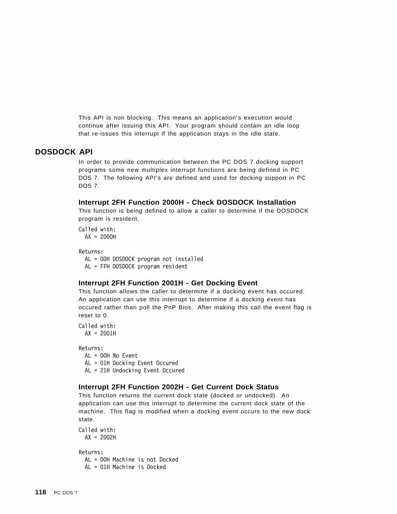
This API is non blocking. This means an application′s execution wouldcontinue after issuing this API. Your program should contain an idle loopthat re-issues this interrupt if the application stays in the idle state.
DOSDOCK APIIn order to provide communication between the PC DOS 7 docking supportprograms some new multiplex interrupt functions are being defined in PCDOS 7. The following API′s are defined and used for docking support in PCDOS 7.
Interrupt 2FH Function 2000H - Check DOSDOCK InstallationThis function is being defined to allow a caller to determine if the DOSDOCKprogram is resident.
Called with:AX = 2000H
Returns:AL = 00H DOSDOCK program not installedAL = FFH DOSDOCK program resident
Interrupt 2FH Function 2001H - Get Docking EventThis function allows the caller to determine if a docking event has occured.An application can use this interrupt to determine if a docking event hasoccured rather than poll the PnP Bios. After making this call the event flag isreset to 0.
Called with:AX = 2001H
Returns:AL = 00H No EventAL = 01H Docking Event OccuredAL = 21H Undocking Event Occured
Interrupt 2FH Function 2002H - Get Current Dock StatusThis function returns the current dock state (docked or undocked). Anapplication can use this interrupt to determine the current dock state of themachine. This flag is modified when a docking event occurs to the new dockstate.
Called with:AX = 2002H
Returns:AL = 00H Machine is not DockedAL = 01H Machine is Docked
118 PC DOS 7

Interrupt 2FH Function AX=43E0H DOS Protected ModeServices CheckPlease refer to Appendix E, “DOS Protected Mode Services” on page 313 fordetails of this function call along with the Interrupt 31H calls to the DPMSdriver.
Appendix A. PC DOS 7 Interrupts 119

Interrupt 2FH Advanced Power Management DriverAll power management functions are accessed through subfunctions ofinterrupt 2FH, function 54H and 53H. The following table lists thesubfunctions. In all calls, undefined bits are reserved and should be set to 0.
The following INT 2Fh APIs (Application Program Interfaces) are defined forDOS APM driver (POWER.EXE) which is APM 1.0 compliant.
The DOS INT 2Fh APIs for APM driver (POWER.EXE) that is 1.1 compliant donot exist from the APM Committee (Microsoft and Intel). The intent of thisdocument is to propose a standard for APM driver (POWER.EXE 1.01), INT2Fh APIs that can utilize APM 1.1 BIOS functionality. The following are theDOS INT 2Fh APIs that are proposed as a standard for APM driver.
The intent of these API′s is to give POWER.EXE control over specific unitdevice, thus resulting in a greater savings to the system unit battery life ascompared to an application coded to the POWER.EXE 1.0 API ′s.
INT 2FFunction
Description
5400 Detect POWER.EXE
5401 Get or set power status
5402 Get or set idle detection strategy
5403 Get or set power saving level
5481 Get idle statistics
5482 Get or set APM polling frequency
INT 2FFunction
Description
530C PM Event First Phase Broadcast
5404 Get Device Power State
5405 Set Device Power State
5406 Enable/Disable device power state
5407 Engage/Disengage power management
Interrupt 2FH Function AX=530BH PM Event BroadcastENTRY:
AX 530BHBX 0001h ; System standby request
0002h ; System suspend request0003h ; Normal Resume notification0004h ; Critical Resume notification0005h ; Battery low notification
120 PC DOS 7

* 0006h ; Power Status Change Notification (1.1)* 0007h ; Update Time Notification (1.1)* 0008h ; Critical System Suspend Notification (1.1)* 0009h ; User System Standby Request Notification (1.1)* 000Ah ; User System Suspend Request Notification (1.1)* 000Bh ; System Standby Resume Notification (1.1)
EXIT:BH 80h ; An application has rejected the
system standby or request.0 ; Otherwise
POWER polls the APM firmware periodically for messages. These messagesare sent to all applicable APM applications. The broadcasted message is anINT 2FH, function 530BH. When POWER polls the APM firmware and detectsa request to switch to the system standby or suspend states, the POWERdevice driver broadcasts this message and waits for this interrupt to return.Handlers of this interrupt can reject these two request. When a request isrejected by setting BH=80H, POWER sends a state change message to theAPM firmware. The APM firmware might still change power states in acritical power situation.
An application that receives a system or standby request might choose toreject it if the application is in a critical section of code. In some othercases, it will prepare for suspend by saving its state and then passing on therequest. Any handler of this message must pass it down the INT 2FH chain(even when rejecting the request). This notifies the other handlers of therequest. Even when a request has been rejected, APM might still choose toenter the suspend state (particularly in a critical low power situation).
The three notifications (normal resume, critical resume, and battery low) alsomight cause applications to respond.
All undefined bits are reserved and should be ignored until they are defined.
Note: This interrupt is provided only for passing on information. It is sentduring a timer tick. So, processing this interrupt should be as fast aspossible. Applications in a critical state should reject this call andshould not attempt to do any maintenance work that results in aninordinate delay during the interrupt. Calling DOS or ROM biosfunctions is not allowed.
Appendix A. PC DOS 7 Interrupts 121

Interrupt 2FH Function AH=530CH PM Event First PhaseBroadcast (1.1)ENTRY:
AX 530CHBX 0001h ; System_Standby_OK
0002h ; System_Suspend_OK0009h ; User_System_Standby_OK000Ah ; User_System_Suspend_OK
EXIT:BH 80h ; An application has rejected the request
0 ; Otherwise
1.1 compliant:
The PM Event First Phase Broadcast (INT 2Fh, AX = 530Ch) API is definedfor POWER.EXE 1.01 that broadcasts first phase PM events for the two phaseprotocol. The following definition allows consistency to the PM eventsdefined at INT 15h level.
Accessing POWER.EXE Controls
Detect POWER.EXEENTRY:
AX 5400H
EXIT:
AX 5400H ;If POWER.EXE is not installedVersion number ;If POWER.EXE is installed
BH 50H ;ASCII “P” characterBL 4DH ;ASCII “M” character
This call must be made before any calls are made to other APIs. This isdone to ensure that calls to POWER are only made when the driver ispresent.
Get or Set Power StatusENTRY:
AX 5401H ;Get or set power statusBH 0 ;Get power status
1 ;Set power statusBL Bit 0 ;POWER.EXE power management
;switch (0=off, 1=on)Bit 1 ;APM firmware power management
;switch (0=off, 1=on)
122 PC DOS 7

Bits 2-7 ;Reserved (set to 0)
EXIT:
AX 0 ;Operation successful02H ;ERROR_PM_ALREADY_CONNECTED03H ;ERROR_PM_NOT_CONNECTED87H ;ERROR_PM_INVALID_PARAMETER
BL ;Current power statusBH ;Power status before call
This function allows selection among any of the combinations of software andhardware power management ON or OFF, as follows:
• POWER=0, APM=0 - Function for all power management is disabled.This is equivalent to POWER OFF.
• POWER=0, APM=1 - Power management at the software level isdisabled. Software idle detection and APM event broadcast toapplications are disabled. APM firmware power management is enabled.This is equivalent to POWER STD.
• POWER=1, APM=1 - This is true advanced power management.Bidirectional communication between POWER.EXE and the APM firmwareis established. POWER.EXE will send CPU_IDLE messages while theAPM firmware is posting power events to be read and broadcasted byPOWER.EXE. This is equivalent to POWER ADV.
If there is no APM firmware, APM=1 is ignored
Get or Set Idle Detection StrategyENTRY:
AX 5402H ;Get or set idle detection strategyBH 0 ;Get current strategy
1 ;Set current strategyBL Bit 0 ;Use INT 16H function 1/11
;(keyboard idle)Bit 1 ;Use INT 28H (DOS idle)Bit 2 ;Use INT 2FH function 1680
;(application)Bit 3 ;Use INT 2AHBits 4-7 ;Reserved
EXIT:
BX ;Current savings level (1-8)
Appendix A. PC DOS 7 Interrupts 123

Interrupt 2FH triggers as soon as it is received. Interrupts 16H and 28H aremonitored over a period of time. The interrupt (16H or 28H) that occurs mostoften is the one used to trigger idles.
An entry value of 0FFH in BL enables all strategies. A value of 0 disablesidle detection through these interrupts (but broadcast of PM events isenabled). Use get or set power status to enable or disable powermanagement.
Get or Set POWER Saving LevelENTRY:
AX 5403H ;Get or set power saving levelBX 0 ;Get current saving level
1-8 ;Set saving level to given number
EXIT:
AX 0 ;Operation successfulBX ;Current saving level
There are 8 different defined power saving levels (1-8). Level 1 is the levelwhere the least power savings are realized. Level 8 is the highest. Thedefault POWER device driver defines ADV:MAX as level 7, ADV:REG as level6, and ADV:MIN as level 3. This API controls two parameters:
• The BaseLineMax for the INT 16H idle detection• The spread of INT 16H timings over the current BaseLine (noise)
The following table shows the current assignments for each level:
Level Base Line % Noise/spread %
1 222 12.5
2 250 25
3 285 37.5
4 333 50
5 400 62.5
6 500 75
7 750 87.5
8 1000 100
124 PC DOS 7
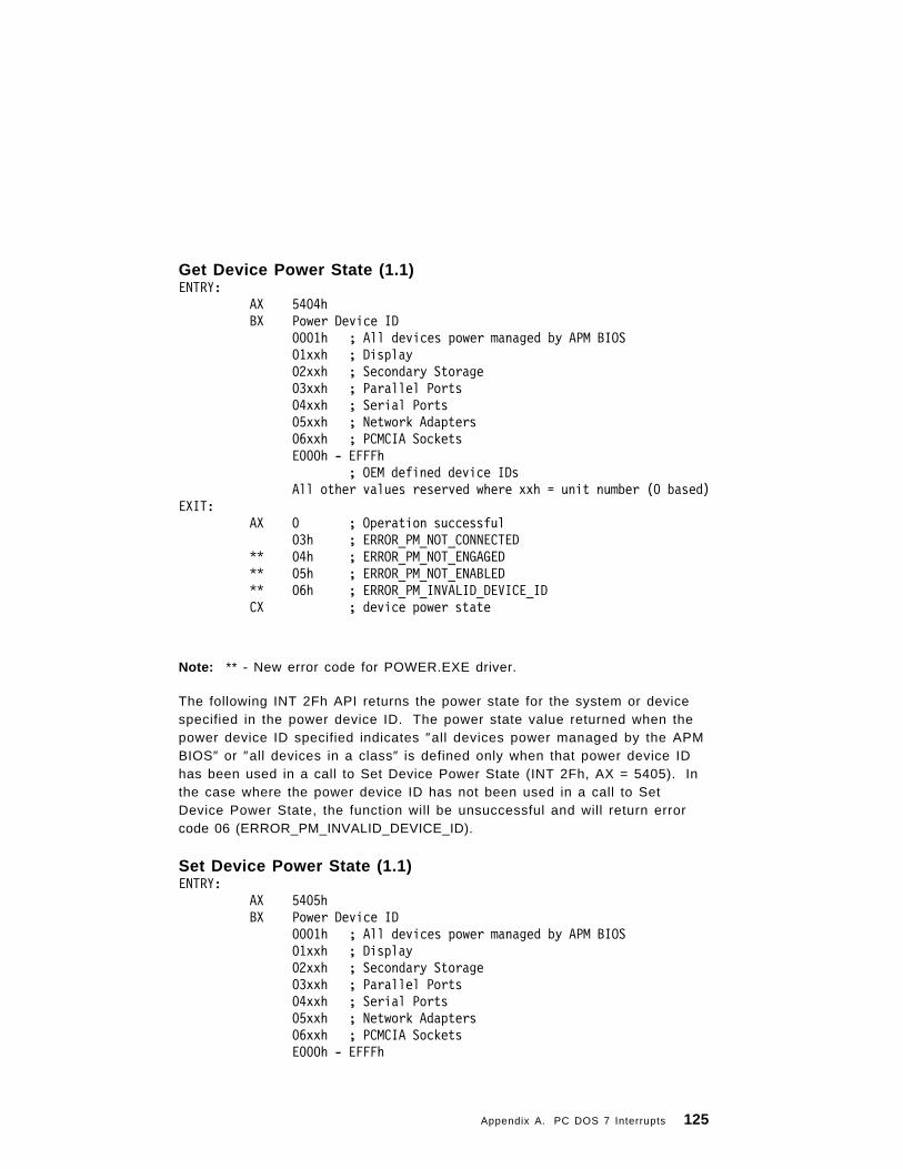
Get Device Power State (1.1)ENTRY:
AX 5404hBX Power Device ID
0001h ; All devices power managed by APM BIOS01xxh ; Display02xxh ; Secondary Storage03xxh ; Parallel Ports04xxh ; Serial Ports05xxh ; Network Adapters06xxh ; PCMCIA SocketsE000h - EFFFh
; OEM defined device IDsAll other values reserved where xxh = unit number (0 based)
EXIT:AX 0 ; Operation successful
03h ; ERROR_PM_NOT_CONNECTED** 04h ; ERROR_PM_NOT_ENGAGED** 05h ; ERROR_PM_NOT_ENABLED** 06h ; ERROR_PM_INVALID_DEVICE_IDCX ; device power state
Note: ** - New error code for POWER.EXE driver.
The following INT 2Fh API returns the power state for the system or devicespecified in the power device ID. The power state value returned when thepower device ID specified indicates ″all devices power managed by the APMBIOS″ or ″all devices in a class″ is defined only when that power device IDhas been used in a call to Set Device Power State (INT 2Fh, AX = 5405). Inthe case where the power device ID has not been used in a call to SetDevice Power State, the function will be unsuccessful and will return errorcode 06 (ERROR_PM_INVALID_DEVICE_ID).
Set Device Power State (1.1)ENTRY:
AX 5405hBX Power Device ID
0001h ; All devices power managed by APM BIOS01xxh ; Display02xxh ; Secondary Storage03xxh ; Parallel Ports04xxh ; Serial Ports05xxh ; Network Adapters06xxh ; PCMCIA SocketsE000h - EFFFh
Appendix A. PC DOS 7 Interrupts 125
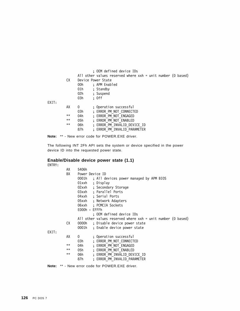
; OEM defined device IDsAll other values reserved where xxh = unit number (0 based)
CX Device Power State00h ; APM Enabled01h ; Standby02h ; Suspend03h ; Off
EXIT:AX 0 ; Operation successful
03h ; ERROR_PM_NOT_CONNECTED** 04h ; ERROR_PM_NOT_ENGAGED** 05h ; ERROR_PM_NOT_ENABLED** 06h ; ERROR_PM_INVALID_DEVICE_ID
87h ; ERROR_PM_INVALID_PARAMETER
Note: ** - New error code for POWER.EXE driver.
The following INT 2Fh API sets the system or device specified in the powerdevice ID into the requested power state.
Enable/Disable device power state (1.1)ENTRY:
AX 5406hBX Power Device ID
0001h ; All devices power managed by APM BIOS01xxh ; Display02xxh ; Secondary Storage03xxh ; Parallel Ports04xxh ; Serial Ports05xxh ; Network Adapters06xxh ; PCMCIA SocketsE000h - EFFFh
; OEM defined device IDsAll other values reserved where xxh = unit number (0 based)
CX 0000h ; Disable device power state0001h ; Enable device power state
EXIT:AX 0 ; Operation successful
03h ; ERROR_PM_NOT_CONNECTED** 04h ; ERROR_PM_NOT_ENGAGED** 05h ; ERROR_PM_NOT_ENABLED** 06h ; ERROR_PM_INVALID_DEVICE_ID
87h ; ERROR_PM_INVALID_PARAMETER
Note: ** - New error code for POWER.EXE driver.
126 PC DOS 7

The following INT 2Fh API will enable or disable power management for aspecified device. When disabled the APM BIOS does not automaticallypower manage the device.
Engage/Disengage power management (1.1)ENTRY:
AX 5407hBX Power Device ID
0001h ; All devices power managed by APM BIOS01xxh ; Display02xxh ; Secondary Storage03xxh ; Parallel Ports04xxh ; Serial Ports05xxh ; Network Adapters06xxh ; PCMCIA SocketsE000h - EFFFh
; OEM defined device IDsAll other values reserved where xxh = unit number (0 based)
CX 0000h ; Disengage power management0001h ; Engage power management
EXIT:AX 0 ; Operation successful
03h ; ERROR_PM_NOT_CONNECTED** 05h ; ERROR_PM_NOT_ENABLED** 06h ; ERROR_PM_INVALID_DEVICE_ID
87h ; ERROR_PM_INVALID_PARAMETER
Note: ** - New error code for POWER.EXE 1.01 driver.
The following INT 2Fh API will engage/disengage power management of thesystem or device. When disengaged, the APM BIOS automatically powermanages the system or device.
Get StatisticsENTRY:
AX 5481H ;Get statisticsDS:SI ;Point to buffer for statisticsBX 0 ;Get idle detection statistics
1 ;Get APM statisticsCX 1CH ;Buffer size in bytes
EXIT:
AX 0 ;Operation successful
Appendix A. PC DOS 7 Interrupts 127

71H ;ERROR_PM_BUFFER_TOO_SMALL87H ;ERROR_PM_INVALID_PARAMETER
This function returns either a structure detailing the efficiency and strategy ofpower usage or a count of APM resumes. The following structures are theidle detection and APM statistics blocks.
STAT_INFO struc ;Idle detection statisticsCPU_ON_TIME dd ? ;Total time CPU is active
;(TIMER TICS)CPU_IDLE_TIME dd ? ;Total time CPU is idle
;(TIMER TICS)TOTAL_IDLE_CALLS dd ? ;
TOTAL_APP_IDLE dd ? ;Total count DO_IDLE;executed through INT 2FH
TOTAL_DOS_YIELD dd ? ;Total count DO_IDLE;executed through INT 28H
TOTAL_KEY_IDLE dd ? ;Total count DO_IDLE;executed through INT 16H
TOTAL_DOS_IDLE dd ? ;Total count DO_IDLE;executed through INT 2AH
STAT_INFO ends
APM_STATS struc ;APM statisticsRESUME_COUNT dw ? ;Total number of resumes
;since last APM_ENABLEAPM_STATS ends
The CPU_ON_TIME value does not include timer ticks which occur while idledetection in POWER is disabled.
Get or Set APM Polling PeriodENTRY:
AX 5482H ;Get or set APM polling periodBX 0 ;Get APM polling period
non zero ;Set APM polling period. Value;equals polling period to set
EXIT:
AX 0 ;Operation successful
BX ;Current APM polling period
This function sets or returns the period at which POWER polls the APMfirmware for PM events. The value is the number of timer ticks betweenpolls.
128 PC DOS 7

APM Error Return Codes and DescriptionsThe error codes that are defined for POWER.EXE device driver for APM 1.0are as follows.
02h ; ERROR_PM_ALREADY_CONNECTED03h ; ERROR_PM_NOT_CONNECTED71h ; ERROR_PM_BUFFER_TOO_SMALL87h ; ERROR_PM_INVALID_PARAMETER
The following new error codes are defined for the POWER.EXE 1.01 devicedriver to utilize APM 1.1 BIOS functionality.
04h ; ERROR_PM_NOT_ENGAGED05h ; ERROR_PM_NOT_ENABLED06h ; ERROR_PM_INVALID_DEVICE_ID07h ; ERROR_PM_DEVIDNOTSET
Interrupt 2FH Function AH=0B7H Get APPEND.EXE InstalledStateAH=B7H is the resident part of APPEND. The Get Installed State function(AL=0) is supported.
AL=2 is the Get APPEND version. This call is for distinguishing between thePC LAN APPEND and the DOS APPEND. On return, if AX=FFFFH then theDOS APPEND is loaded.
AL=4 is the Get APPEND Path Pointer (DOS APPEND only). On return ES:DIpoints to the currently active APPEND path.
AL=6 is the Get APPEND Function State (DOS APPEND only).
BX is returned with bits set indicating if APPEND is currently enabled andwhat functions are in effect.
Note: The functions in effect do not change whether or not APPEND isdisabled.
AL=7 Set function state (DOS APPENDonly)
Bit Function in effect if bit is on
0 APPEND enabled
13 /PATH
14 /E
15 /X
Appendix A. PC DOS 7 Interrupts 129

On input BX is the new setting for all functions.The suggested procedure is to get the current functionstate, turn on or turn off the desired bits, thenuse this call to set the function state.
AL=11H Set Return Found Name State (DOS APPENDonly)
On request AL=17, a process system state flag is set. If this flag is set, thenon the next ASCIIZ 3DH, 43H or 6CH function call within Interrupt 21H thatAPPEND processes, APPEND returns the name it finds to the applicationfilename buffer. This name may be different from the one the applicationoffered. The application must provide enough space for the found name.After APPEND has processed an Interrupt 21H, it resets the Return FoundName state. The following is an example of this process.
MOV AH,0B7H ; Indicate APPENDMOV AL,0 ; Get installed stateINT 2FHCMP AL,0 ; APPEND installed?JE NOT_INSTALLED
MOV AH,0B7H ; Indicate APPENDMOV AL,2 ; Get APPEND versionINT 2FHCMP AX,-1 ; DOS version?
PC_LAN_APPEND ; AX<> -1 means PC LANJNE APPEND
; The following functions are valid only if PC DOS 7 APPEND
MOV AH,0B7H ; Indicate APPENDMOV AL,4 ; Get APPEND path pointerINT 2FH
; ES:DI = address of APPEND path; (Buffer is 128 characters long)
MOV AH,0B7H ; Indicate APPENDMOV AL,6 ; Get function stateINT 2FH
; BX = function state; 8000H = /X is on; 4000H = /E is on; 2000H = /PATH is on; 0001H = APPEND enabled; If off, similar to null
130 PC DOS 7

; APPEND path; Set on by any non-status; occurrence of APPEND
MOV AH,0B7H ; Indicate APPENDMOV AL,7 ; Set function stateMOV BX,state ; New stateINT 2FH
MOV AH,0B7H ; Indicate APPENDMOV AL,11H ; Set Return Found
; Name stateINT 2FH
Example 2FH HandlerMYNUM DB X ; X = The specific AH
; multiplex number.INT 2F NEXT DD ? ; Chain locationINT 2F:
ASSUME DS:NOTHING,ES:NOTHING,SS:NOTHING
CMP AH,MYNUMJE MINEJMP INT 2F NEXT ; Chain to next
; 2FH Handler
MINE:
CMP AL,0F8HJB DO FUNCIRET ; IRET on reserved
; functions
DO FUNC:
OR AL,ALJNE NON INSTALL ; Non Get Installed
; State requestMOV AL,0FFH ; Say I′ m hereIRET ; All done
NON INSTALL:...
Appendix A. PC DOS 7 Interrupts 131

Installing the HandlerThe following example contains the functions necessary to install a handler:
MOV AH,MYNUMXOR AL,ALINT 2FH ; Ask if already
; installedOR AL,ALJZ OK INSTALL
BAD INSTALL: ; Handler already installed
OK INSTALL: ; Install my; handler
MOV AL,2FHMOV AH,GET INTERRUPT VECTORINT 21H ; Get multiplex
; vectorMOV WORD PTR INT 2F NEXT+2,ESMOV WORD PTR INT 2F NEXT,BXMOV DX,OFFSET INT 2FMOV AL,2FHMOV AH,SET INTERRUPT VECTORINT 21H ; Set multiplex
; vector...
Interrupt 30H-3FH Reserved for PC DOS 7These interrupts are reserved for PC DOS 7 use.
132 PC DOS 7

Appendix B. PC DOS 7 Function Calls
Number Function Name00H Program terminate01H Console input with echo02H Display output03H Auxiliary input04H Auxiliary output05H Printer output06H Direct console I/O07H Direct console input without echo08H Console input without echo09H Display string0AH Buffered keyboard input0BH Check standard input status0CH Clear keyboard buffer, invoke a keyboard function0DH Disk reset0EH Select disk0FH Open file10H Close file11H Search for first entry12H Search for next entry13H Delete file14H Sequential read15H Sequential write16H Create file17H Rename file18H Reserved by PC DOS 719H Current disk1AH Set disk transfer address1BH Allocation table information1CH Allocation table information for specific device1DH Reserved by PC DOS 71EH Reserved by PC DOS 71FH Get Default Drive Parameter Block20H Reserved by PC DOS 721H Random read22H Random write23H File size24H Set relative record field25H Set interrupt vector26H Create new program segment27H Random block read
Copyright IBM Corp. 1995 133

28H Random block write29H Parse filename2AH Get date2BH Set date2CH Get time2DH Set time2EH Set or reset verify switch2FH Get disk transfer address30H Get PC DOS 7 version number31H Terminate process and remain resident32H Get Drive Parameter Block33H Get or Set system value34H Get InDOS Flag Address35H Get interrupt vector36H Get disk free space37H Reserved by PC DOS 738H Get or set country dependent information39H Create subdirectory (MKDIR)3AH Remove subdirectory (RMDIR)3BH Change current directory (CHDIR)3CH Create a file (CREAT)3DH Open a file3EH Close a file handle3FH Read from a file or device40H Write to a file or device41H Delete a file from a specified directory (UNLINK)42H Move file read/write pointer (LSEEK)43H Change file mode (CHMOD)44H I/O control for devices (IOCtl)45H Duplicate a file handle (DUP)46H Force a duplicate of a file handle (FORCDUP)47H Get current directory48H Allocate memory49H Free allocated memory4AH Modify allocated memory blocks (SETBLOCK)4BH Load or execute a program (EXEC)4CH Terminate a process (EXIT)4DH Get return code of a subprocess (WAIT)4EH Find first matching file (FIND FIRST)4FH Find next matching file (FIND NEXT)50H Set Program Segment Prefix Address51H Get Program Segment Prefix Address52H Reserved by PC DOS 753H Reserved by PC DOS 7
134 PC DOS 7

54H Get verify setting55H Reserved by PC DOS 756H Rename a file57H Get or set a file′s date and time5800H Get Allocation Strategy5801H Set Allocation Strategy5802H Get Upper-Memory Link5803H Set Upper-Memory Link59H Get extended error5AH Create unique file5BH Create new file5CH Lock or unlock file access5D0AH Set Extended Error5E00H Get machine name5E02H Set printer setup5E03H Get printer setup5F02H Get redirection list entry5F03H Redirect device5F04H Cancel redirection60H Reserved by PC DOS 761H Reserved by PC DOS 762H Get PSP address63H Reserved by PC DOS 764H Reserved by PC DOS 765H Get extended country information66H Get or set global code page67H Set handle count68H Commit file69H Reserved by PC DOS 76AH Reserved by PC DOS 76BH Reserved by PC DOS 76CH Extended open or create
Using PC DOS 7 Function CallsMost function calls require input to be passed to them in registers. Aftersetting the appropriate register values, issue the function calls in either ofthe following ways:
• The preferred method is to place the function number in AH and issueinterrupt 21H.
• Place the function number in AH and execute a call to offset 50H in yourprogram segment prefix.
Appendix B. PC DOS 7 Function Calls 135

Program Code FragmentsIn each of the function call descriptions in this chapter, the input, output andmethod of use are described using a small program code fragment. Thesefragments are written in IBM PC Assembler Language.
.COM ProgramsThe descriptions assume that the program is an .EXE, not a .COM program.If a .COM program is desired, do not include either of the followinginstructions:
MOV ES,SEG —orMOV DS,SEG —
Notes:
1. Some FCB function calls do not permit invalid characters (0DH− 2 9 H).
2. Device names cannot end in a colon.
3. The contents of the AX register can be altered by any of the functioncalls. Even though no error code is returned in AX, it is possible that AXhas been changed.
PC DOS 7 RegistersPC DOS 7 uses the following registers, pointers, and flags when executinginterrupts and function calls:
RegisterDefinition
GeneralRegisters
AXAHAL
Accumulator (16-bit)Accumulator high-order byte (8-bit)Accumulator low-order byte (8-bit)
BXB HBL
Base (16-bit)Base high-order byte (8-bit)Base low-order byte (8-bit)
CXCHCL
Count (16-bit)Count high-order byte (8-bit)Count low-order byte (8-bit)
DXDHDL
Data (16-bit)Data high-order (8-bit)Data low-order (8-bit)
Flags OF,DF,IF,TF,SF,ZF,AF,PF,CF
136 PC DOS 7

RegisterDefinition Pointers
SP Stack pointer (16-bit)
BP Base pointer (16-bit)
IP Instruction pointer (16-bit)
RegisterDefinition
SegmentRegisters
CS Code segment (16-bit)
DS Data segment (16-bit)
SS Stack segment (16-bit)
ES Extra segment (16-bit)
RegisterDefinition
IndexRegisters
DI Destination index (16-bit)
SI Source index (16-bit)
Register Numbering ConventionEach register is 16 bits long and is divided into a high and low byte. Eachbyte is 8 bits long. The bits are numbered from right to left. The low bytecontains bits 0 through 7 and the high byte contains bits 8 through 15. Thechart below shows the hexadecimal values assigned to each bit.
High Byte Low Byte
Bit 15 14 13 12 11 10 9 8 7 6 5 4 3 2 1 0
Hex value 8 4 2 1 8 4 2 1 8 4 2 1 8 4 2 1
PC DOS 7 Internal StackWhen PC DOS 7 gains control, it switches to an internal stack. Userregisters are preserved unless information is passed back to the requesteras indicated in the specific requests. The user stack needs to be sufficient toaccommodate the interrupt system. It is recommended that the user stackbe 200H in addition to what the user needs.
Appendix B. PC DOS 7 Function Calls 137

Responding to ErrorsHandle function calls report an error by setting the carry flag and returningthe error code in AX. FCB function calls report an error by returning FFH inAL.
Extended error support (59H) provides a common set of error codes andspecific error information such as error classification, location, andrecommended action. In most critical cases, applications can analyze theerror code and take specific action. Recommended actions are intended forprograms that do not understand the error codes. Programs can takeadvantage of extended error support both from interrupt 24H critical errorhandlers and after issuing interrupt 21H function calls. Do not code tospecific error codes.
Extended Error CodesHexadecimalCode
DecimalCode Meaning
01H 1 Invalid function number02H 2 File not found03H 3 Path not found04H 4 Too many open files (no handles left)05H 5 Access denied06H 6 Invalid handle07H 7 Memory control blocks destroyed08H 8 Insufficient memory09H 9 Invalid memory block address0AH 10 Invalid environment0BH 11 Invalid format0CH 12 Invalid access code0DH 13 Invalid data0EH 14 Reserved0FH 15 Invalid drive was specified10H 16 Attempt to remove the current directory11H 17 Not same device12H 18 No more fi les13H 19 Attempt to write on write-protected diskette14H 20 Unknown unit15H 21 Drive not ready16H 22 Unknown command17H 23 Cyclic redundancy check (CRC) — part of diskette is
bad18H 24 Bad request structure length19H 25 Seek er ror1AH 26 Unknown media type1BH 27 Sector not found1CH 28 Printer out of paper1DH 29 Write fault1EH 30 Read fault1FH 31 General fai lure20H 32 Sharing violation
138 PC DOS 7

HexadecimalCode
DecimalCode Meaning
21H 33 Lock violation22H 34 Invalid disk change23H 35 FCB unavailable24H 36 Sharing buffer overflow25H 37 Reserved by PC DOS 726H 38 Unable to complete file operation27H− 3 1 H 39− 4 9 Reserved by PC DOS 732H 50 Network request not supported33H 51 Remote computer not listening34H 52 Duplicate name on network35H 53 Network path not found36H 54 Network busy37H 55 Network device no longer exists38H 56 NETBIOS command limit exceeded39H 57 System error; NETBIOS error3AH 58 Incorrect response from network3BH 59 Unexpected network error3CH 60 Incompatible remote adapter3DH 61 Print queue full3EH 62 Not enough space for print file3FH 63 Print fi le was cancelled40H 64 Network name was deleted41H 65 Access denied42H 66 Network device type incorrect43H 67 Network name not found44H 68 Network name limit exceeded45H 69 NETBIOS session limit exceeded46H 70 Sharing temporari ly paused47H 71 Network request not accepted48H 72 Print or disk redirection is paused49H− 4 FH 73− 7 9 Reserved50H 80 File exists51H 81 Reserved52H 82 Cannot make directory entry53H 83 Fail on INT 2454H 84 Too many redirections55H 85 Duplicate redirection56H 86 Invalid password57H 87 Invalid parameter58H 88 Network data fault59H 89 Function not supported by network5AH 90 Required system component not installed
Error ClassesHexadecimalValue
DecimalValue Description
01H 1 Out of Resource: Example: out of space or channels.02H 2 Temporary Situation: Something expected to disappear
with time. This is not an error condition, but atemporary situation such as a locked file.
03H 3 Authorization: Permission problem.
Appendix B. PC DOS 7 Function Calls 139

HexadecimalValue
DecimalValue Description
04H 4 Internal: Internal error in system software. Probableproblem with system software rather than a user orsystem failure.
05H 5 Hardware Failure: A serious problem not the fault ofuser program.
06H 6 System Failure: Serious failure of system software notthe fault of the user, such as missing or incorrectconfiguration fi les.
07H 7 Application Program Error: Inconsistent requests.08H 8 Not Found: File or item not found. Inconsistent
requests.09H 9 Bad Format: File or value in invalid format or type;
unsuitable.0AH 10 Locked: Locked file or item.0BH 11 Media: Media failure such as incorrect disk, CRC error,
or defective media.0CH 12 Already Exists: Duplication error, such as declaring a
machine name that already exists.0DH 13 Unknown: Classification does not exist or is
inappropriate.
ActionsHexadecimalCode
DecimalCode Description
01H 1 Retry: Retry a few times, then prompt user todetermine if the program should continue or beterminated.
02H 2 Delay Retry: Retry several times after pause, thenprompt user to determine if the program shouldcontinue or be terminated.
03H 3 User: If the input was entered by a user, advisereentry. The error, however, may have occurred in theprogram itself, such as a bad drive letter or badfilename specification.
04H 4 Abort: Abort application with cleanup. The applicationcannot proceed, but the system is in an orderly stateand it is safe to stop the application.
05H 5 Immediate Exit: Stop application immediately withoutclearing registers. Do not use the application to closefiles or update indexes, but exit as soon as possible.
06H 6 Ignore: Ignore.07H 7 Retry After User Intervention: The user needs to
perform some action such as removing a diskette andinserting a different one. Then retry the operation.
140 PC DOS 7

Locus (Location)HexadecimalValue
DecimalValue Description
01H 1 Unknown: Not specific; not appropriate.02H 2 Block Device: Related to random access mass disk
storage.03H 3 Net: Related to the network.04H 4 Serial Device: Related to serial devices.05H 5 Memory: Related to random access memory.
Appendix B. PC DOS 7 Function Calls 141

00H — Program Terminate
PurposeStops the execution of a program.
ExamplesMOV AH,00H ; Function Call — Terminate ProgramINT 21H ; Issue request to DOS
; No return
CommentsThe terminate, Ctrl-Break, and critical error exit addresses are restored tothe values they had on entry to the terminating program, from the valuessaved in the program segment prefix. All file buffers are flushed and thehandles opened by the process are closed. Any files that have changed inlength and not closed are not recorded properly in the directory. Controltransfers to the terminate address. This call performs exactly the samefunction as interrupt 20H. It is the program′s responsibility to ensure that theCS register contains the segment address of its program segment prefixcontrol block before calling this function.
Function 4CH — Terminate a Process is the preferred method for ending aprogram.
142 PC DOS 7

01H — Console Input with Echo
PurposeWaits for a character to be read at the standard input device (unless one isready), then echoes the character to the standard output device and returnsthe character in AL.
ExamplesMOV AH,01H ; Function Call — keyboard inputINT 21H ; Issue request to DOSMOV Char,AL ; Save characterCMP AL,0 ; Extended character ?JNE Normal Char ; No!MOV AH,01H ; Function Call — keyboard inputINT 21H ; Issue request to DOSMOV ExtChar,AL ; Save extended character
Normal Char:
-----
Character LABEL WORD ; Complete characterChar DB ? ; Character bufferExtChar DB ? ; Character buffer
CommentsThe character is checked for a Ctrl-Break. If Ctrl-Break is detected, aninterrupt 23H is executed.
For function call 01H, extended ASCII codes require two function calls. Thefirst call returns 00H as an indicator that the next call will return an extendedcode.
Appendix B. PC DOS 7 Function Calls 143
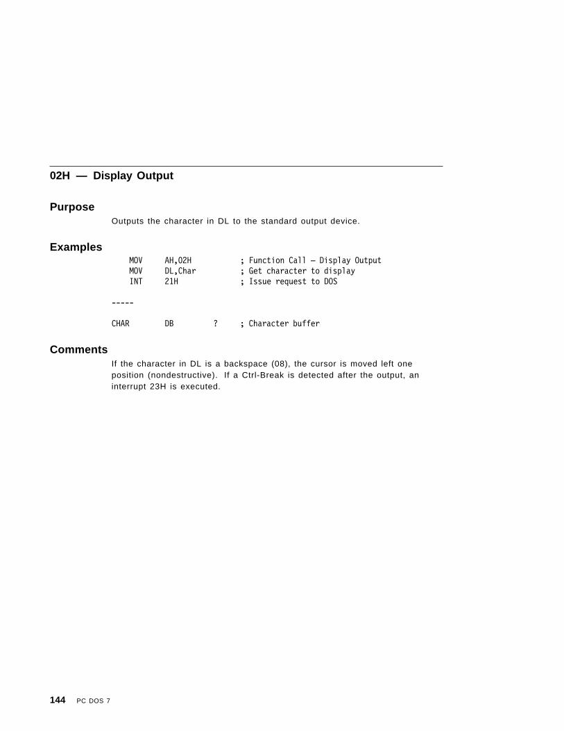
02H — Display Output
PurposeOutputs the character in DL to the standard output device.
ExamplesMOV AH,02H ; Function Call — Display OutputMOV DL,Char ; Get character to displayINT 21H ; Issue request to DOS
-----
CHAR DB ? ; Character buffer
CommentsIf the character in DL is a backspace (08), the cursor is moved left oneposition (nondestructive). If a Ctrl-Break is detected after the output, aninterrupt 23H is executed.
144 PC DOS 7

03H — Auxiliary Input
PurposeWaits for a character from the standard auxiliary device, then returns thatcharacter in AL.
ExamplesMOV AH,03H ; Function Call — Auxiliary InputINT 21H ; Issue request to DOSMOV Char,AL ; Save character
-------
CHAR DB ? ; Character buffer
CommentsAuxiliary (AUX) support is unbuffered and noninterrupt driven.
At startup, PC DOS 7 initializes the first auxiliary port to 2400 baud, no parity,one-stop bit, and 8-bit word.
The auxiliary function calls (03H and 04H) do not return status or error codes.For greater control, you should use the ROM BIOS routine (interrupt 14H) orwrite an AUX device driver and use IOCtl.
Appendix B. PC DOS 7 Function Calls 145

04H — Auxiliary Output
PurposeOutputs the character in DL to the standard auxiliary device.
ExamplesMOV AH,04H ; Function Call — Auxiliary Output
MOV DL,Char ; Get character to outputINT 21H ; Issue request to DOS
; Nothing returned
-------
CHAR DB ? ; Character buffer
CommentsIf the character in DL is a backspace (08), the cursor is moved left oneposition (nondestructive). If a Ctrl-Break is detected after the output, aninterrupt 23H is executed.
146 PC DOS 7

05H — Printer Output
PurposeOutputs the character in DL to the standard printer device.
ExamplesMOV AH,05H ; Function Call — Printer OutputMOV DL,Char ; Get character to outputINT 21H ; Issue request to DOS
; Nothing returned
--------
CHAR DB ? ; Character buffer
Appendix B. PC DOS 7 Function Calls 147

06H — Direct Console I/O
PurposeGets a character from the standard input device if one is ready, or outputs acharacter to the standard output device.
ExamplesIn loop:MOV AH,06H ; Function Call — Direct Console I/OMOV DL,-1 ; 0FFH for inputINT 21H ; Issue request to DOSJZ In loop ; No character yet on inputMOV Char,AL ; Save characterCMP AL,0 ; Extended Character ?JNE Normal Char ; No!MOV AH,07H ; Function Call — Keyboard InputINT 21H ; Issue request to DOSMOV ExtChar,AL ; Save extended character
Normal Char:
or
MOV AH,06H ; Function Call — Direct Console I/OMOV DL,Char ; Output character to display (not 0FFH)INT 21H ; Issue request to DOS
-----
Character LABEL WORD ; Complete characterChar DB ? ; Character bufferExtChar DB ? ; Character buffer
CommentsIf DL is FFH, AL returns with the 0 flag clear and an input character from thestandard input device, if one is ready. If a character is not ready, the 0 flagwill be set.
If DL is not FFH, DL is assumed to have a valid character that is output to thestandard output device. This function does not check for Ctrl-Break, orCtrl-PrtSc.
For function call 06H, extended ASCII codes require two function calls. Thefirst call returns 00H as an indicator that the next call will return an extendedcode.
148 PC DOS 7
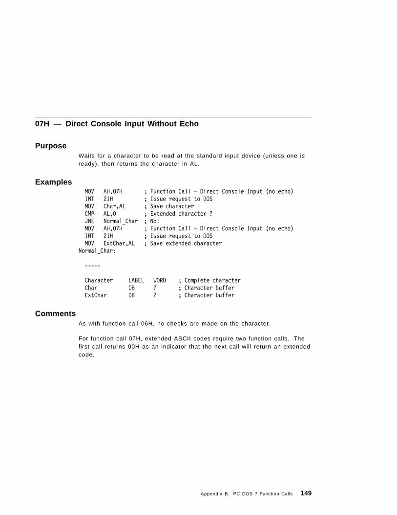
07H — Direct Console Input Without Echo
PurposeWaits for a character to be read at the standard input device (unless one isready), then returns the character in AL.
ExamplesMOV AH,07H ; Function Call — Direct Console Input (no echo)INT 21H ; Issue request to DOSMOV Char,AL ; Save characterCMP AL,0 ; Extended character ?JNE Normal Char ; No!MOV AH,07H ; Function Call — Direct Console Input (no echo)INT 21H ; Issue request to DOSMOV ExtChar,AL ; Save extended character
Normal Char:
-----
Character LABEL WORD ; Complete characterChar DB ? ; Character bufferExtChar DB ? ; Character buffer
CommentsAs with function call 06H, no checks are made on the character.
For function call 07H, extended ASCII codes require two function calls. Thefirst call returns 00H as an indicator that the next call will return an extendedcode.
Appendix B. PC DOS 7 Function Calls 149

08H — Console Input Without Echo
PurposeWaits for a character to be read at the standard input device (unless one isready) and returns the character in AL.
Examples
MOV AH,08H ; Function Call — Console Input (no echo) INT 21H ; Issue request to DOS MOV Char,AL ; Save character CMP AL,0 ; Extended character ? JNE Normal Char; No! MOV AH,08H ; Function Call — Console Input (no echo) INT 21H ; Issue request to DOS MOV ExtChar,AL ; Save extended characterNormal Char:-----
Character LABEL WORD ; Complete character Char DB ? ; Character buffer ExtChar DB ? ; Character buffer
CommentsThe character is checked for Ctrl-Break. If Ctrl-Break is detected, aninterrupt 23H is executed.
For function call 08H, extended ASCII codes require two function calls. Thefirst call returns 00H as an indicator that the next call will return an extendedcode.
150 PC DOS 7

09H — Display S tring
PurposeSends the characters in the string to the standard output device.
ExamplesMOV AX,SEG String MOV DS,AX ;Set DS:DX to string MOV DX,OFFSET String MOV AH,09H ;Function Call - Display String INT 21H ;Issue request to DOS
-----
String DB ″This string ends at the first Dollar″DB 0DH,0AHDB ″$″
CommentsThe character string in memory must be terminated by a $ (24H). Eachcharacter in the string is output to the standard output device in the sameform as function call 02H.
ASCII codes 0DH and 0AH represent carriage return and line feed,respectively.
Appendix B. PC DOS 7 Function Calls 151

0AH — Buffered Keyboard Input
PurposeReads characters from the standard input device and places them in thebuffer beginning at the third byte.
ExamplesMOV AX,SEG Buffer MOV DS,AX ;Set DS:DX to return Buffer MOV DX,OFFSET Buffer MOV AH,0AH ;Function Call-Buffered
;Keyboard Input INT 21H ;Issue request to DOS
------
Buffer DB 128 ; Max length of inputCurLen DB ? ; Number of characters input
; (excludes Return (0DH)) CurText DB 128 DUP(?) ; Up to 128 characters allowed
CommentsThe first byte of the input buffer specifies the number of characters the buffercan hold. This value cannot be 0. Reading the standard input device andfilling the buffer continues until Enter is read. If the buffer fills to one lessthan the maximum number of characters it can hold, each additionalcharacter read is ignored and causes the bell to ring, until Enter is read. Thesecond byte of the buffer is set to the number of characters received,excluding the carriage return (0DH), which is always the last character.
152 PC DOS 7

0BH — Check Standard Input Status
PurposeChecks if there is a character available from the standard input device.
Examples In LOOP:
MOV AH,0BH ; Function Call — Check InputINT 21H ; Issue request to DOSCMP AL,-1 ; 0FFH indicates character availableJNE In LOOP
CommentsIf a character is available from the STDIN device, AL is FFH. Otherwise, ALis undefined. If a Ctrl-Break is detected, an interrupt 23H is executed.
Appendix B. PC DOS 7 Function Calls 153

0CH — Clear Keyboard Buffer and Invoke a Keyboard Function
PurposeClears the standard input device of any characters, then executes thefunction call number in AL.
ExamplesMOV AH,0CH ; Function Call — Clear keyboard &
; Invoke functionMOV AL,Function ; Function Call to execute
; (only 01H, 06H, 07H, 08H, and 0AH are allowed).INT 21H ; Issue request to DOS
; Output depends on Function Call selected
154 PC DOS 7
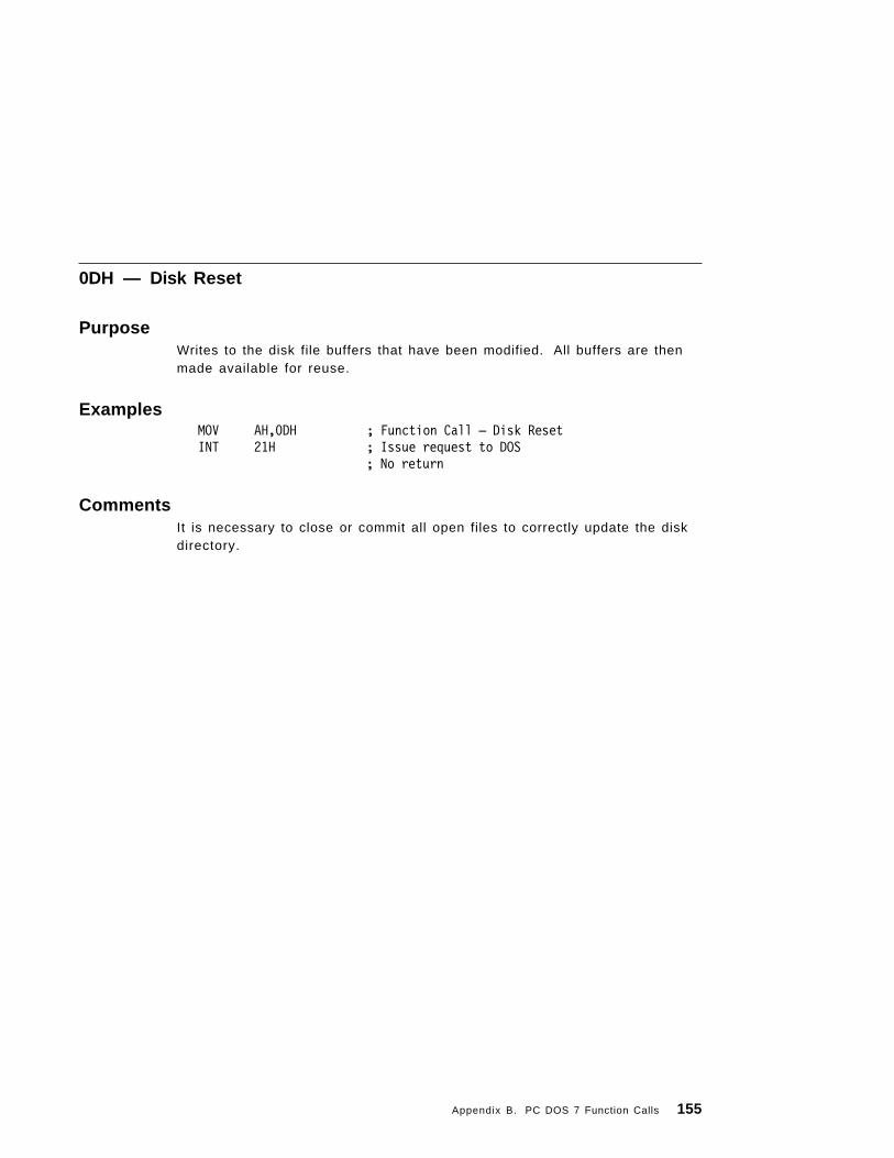
0DH — Disk Reset
PurposeWrites to the disk file buffers that have been modified. All buffers are thenmade available for reuse.
ExamplesMOV AH,0DH ; Function Call — Disk ResetINT 21H ; Issue request to DOS
; No return
CommentsIt is necessary to close or commit all open files to correctly update the diskdirectory.
Appendix B. PC DOS 7 Function Calls 155

0EH — Select Disk
PurposeSelects the drive specified in DL (0=A, 1=B, etc.) (if valid) as the defaultdrive.
ExamplesMOV AH,0EH ; Function Call — Select DiskMOV DL,Drive ; Drive to select (0=A:, 1=B:, ...)INT 21H ; Issue request to DOSMOV LastDrive,AL : Save max drive number (1=A:, 2=B:, ...)MOV AH,19H ; Function Call — Get Current DiskINT 21H ; Issue request to DOSCMP AL,DL ; Selected drive = requestedJNE Error ; No, Error!
-----
Drive DB ; New Drive to selectLastDrive DB ; Highest Valid Drive
CommentsThe total number of unique drive letters, including diskette and hard diskdrives, that can be referenced is returned in AL. The value in AL is equal tothe value of LASTDRIVE in CONFIG.SYS or the total number of installeddevices, whichever is greater. For PC DOS 7 5 is the minimum valuereturned in AL. If the system has only one diskette drive, it is counted as twoto be consistent with the philosophy of thinking of the system as havinglogical drives A and B.
156 PC DOS 7

0FH — Open File
PurposeSearches the current directory for the named file and AL returns FFH if it isnot found. If the named file is found, AL returns 00H and the FCB is filled asdescribed below.
Examples MOV AX,SEG FCB ;Address FCB Parameter Block MOV DS,AX MOV DX,OFFSET FCB MOV AH,0FH ;Function Call-FCB Open INT 21H ;Issue request to DOS
-----
FCB LABEL BYTEDrive DB 0 ; Drive (0=Current, 1=A, 2=B, ...)FName DB ″FILENAME″ ; File Name (blank padded)Ext DB ″EXT″ ; File Extension (blank padded)
DB 25 DUP(0) ; Filled in by PC DOS 7
CommentsAL is 00H if the file is opened.
AL is FFH if the file was not opened.
Use Function Call 59H (Get Extended Error) to determine the actual errorcondition.
If the drive code was 0 (default drive), it is changed to the actual drive used(1=A, 2=B, and so on). This allows changing the default drive withoutinterfering with subsequent operations on this file. The current block field(FCB bytes C-D) is set to 0. The size of the record to be worked with (FCBbytes E-F) is set to the system default of 80H. The size of the file and thedate are set in the FCB from information obtained from the directory. Youcan change the default value for the record size (FCB bytes E-F) or set therandom record size and/or current record field. Perform these actions afterthe open, but before any disk operations.
The file is opened in compatibility mode. For information on compatibilitymode, refer to function call 3DH.
Appendix B. PC DOS 7 Function Calls 157

10H — Close File
PurposeCloses a file.
Examples MOV AX,SEG FCB ; Address FCB Parameter Block MOV DS,AX MOV DX,OFFSET FCB MOV AH,10H ; Function Call-FCB Close INT 21H ; Issue request to DOS CMP AL,0 ; File Closed? JNE Error ; No, Error!
-----
FCB LABEL BYTE; Contents set by previous operations
CommentsAL is 00H if the file is closed.
AL is FFH if the file was not closed.
Use Function Call 59H (Get Extended Error) to determine the actual errorcondition.
This function call must be executed on open files after file writes, and wehighly recommend that it be used on all files. If the file is not found in itscorrect position in the current directory, it is assumed the disk was changedand AL returns FFH. Otherwise, the directory is updated to reflect the statusin the FCB, the buffers for that file are flushed, and AL returns 00H.
158 PC DOS 7

11H — Search for First Entry
PurposeSearches the current directory for the first matching filename.
Examples MOV AX,SEG DTA ; Address Buffer for found file MOV DS,AX ; information MOV DX,OFFSET DTA MOV AH,1AH ; Function Call-Set DTA address INT 21H ; Issue request to DOS MOV AX,SEG FCB ; Address FCB parameter block MOV DS,AX MOV DX,OFFSET FCB MOV AH,11H ; Function Call-FCB search first INT 21H ; Issue request to DOS CMP AL,0 ; File found? JNE Error ; No, Error!
-----
FCB LABEL BYTE Fdrive DB 0 ; Drive (0=Current, 1=A, 2=B, ...)Fname DB ″FILENAME″ ; File name (blank padded, may use ?)Fext DB ″EXT″ ; File extension (blank padded, may use ?)
DB 25 DUP(0) ; Filled in by DOS
DTA LABEL BYTE Ddrive DB ? ; DriveDname DB ″????????″ ; File Name (blank padded)Dext DB ″???″ ; File Extension (blank padded)
DB 25 DUP(0) ; Filled in by PC DOS 7
CommentsAL is 00H if the file is found.
AL is FFH if the file was not found.
Use Function Call 59H (Get Extended Error) to determine the actual errorcondition.
The current disk directory is searched for the first matching filename. If noneis found, AL returns FFH. Global filename characters are allowed in the
Appendix B. PC DOS 7 Function Calls 159

filename and extension. If a matching filename is found, AL returns 00H andthe locations at the disk transfer address are set as follows:
• If the FCB provided for searching was an extended FCB, the first byte atthe disk transfer address is set to FFH followed by 5 bytes of 0, then theattribute byte from the search FCB, then the drive number used (1=A,2=B, etc.), then the 32 bytes of the directory entry. Thus, the disktransfer address contains a valid unopened extended FCB with the samesearch attributes as the search FCB.
• If the FCB provided for searching was a standard FCB, then the first byteis set to the drive number used (1=A, 2=B), and the next 32 bytescontain the matching directory entry. Thus, the disk transfer addresscontains a valid unopened normal FCB.
Note: If an extended FCB is used, the following search pattern is used:
1. If the attribute is 0, only normal file entries are found. Entries forvolume label, sub-directories, hidden and system files, are notreturned.
2. If the attribute field is set for hidden or system files, or directoryentries, it is an inclusive search. All normal file entries, plus allentries matching the specified attributes, are returned. To look atall directory entries except the volume label, the attribute bytemay be set to hidden + system + directory (all 3 bits on).
3. If the attribute field is set for the volume label, it is considered anexclusive search, and only the volume label entry is returned.
160 PC DOS 7

12H — Search for Next Entry
PurposeSearches the current directory for the next matching filename.
ExamplesMOV AX,SEG DTA ; Address Buffer for found fileMOV DS,AX ; InformationMOV DX,OFFSET DTAMOV AH,1AH ; Function Call-Set DTA addressINT 21H ; Issue request to DOSMOV AX,SEG FCB ; Address FCB Parameter BlockMOV DS,AXMOV DX,OFFSET FCBMOV AH,12H ; Function Call-FCB Search NextINT 21H ; Issue request to DOSCMP AL,0 ; File found?JNE Error ; No, Error!
-----
FCB LABEL BYTE; As set by FCB Search First
DTA LABEL BYTEDrive DB ? ; DriveFname DB ″????????″ ; File Name (blank padded)Ext DB ″???″ ; File Extension (blank padded)
DB 25 DUP(0) ; Filled in by PC DOS 7
CommentsAL is 00H if the file is found. AL is FFH if the file was not found. UseFunction Call 59H (Get Extended Error) to determine the actual errorcondition.
After a matching filename has been found using function call 11H, function12H may be called to find the next match to an ambiguous request.
The DTA contains information from the previous Search First or Search Next.All of the FCB, except for the name/extension field, is used to keepinformation necessary for continuing the search, so no disk operations maybe performed if this FCB is between a previous function 11H or 12H call andthis one.
Appendix B. PC DOS 7 Function Calls 161

13H — Delete File
PurposeDeletes all current directory entries that match the specified filename. Thespecified filename cannot be read-only.
Examples MOV AX,SEG FCB ;Address FCB Parameter Block MOV DS,AX MOV DX,OFFSET FCB MOV AH,13H ;Function Call-FCB Delete File INT 21H ;Issue request to DOS CMP AL,0 ;File(s) Deleted? JNE Error ;No, Error!
-----
FCB LABEL BYTE Drive DB 0 ; DriveFName DB Filename ; File Name (blank padded, may use ?)Ext DB Ext ; File Extension (blank padded, may use ?)
DB 25 DUP(0) ; Filled in by DOS
CommentsAL is 00H if the file is found.
AL is FFH if the file was not found.
Use Function Call 59H (Get Extended Error) to determine the actual errorcondition.
All matching current directory entries are deleted. The global filenamecharacter “?” is allowed in the filename or extension. If no directory entriesmatch, AL returns FFH; otherwise AL returns 00H.
If the file is specified in read-only mode, the file is not deleted.
Note: Close open files before deleting them.
Network Access Rights: Requires Create access rights.
162 PC DOS 7

14H — Sequential Read
PurposeLoads the record addressed by the current block (FCB bytes C-D) and thecurrent record (FCB byte 1F) at the disk transfer address (DTA), then therecord address is increased.
Examples MOV AX,SEG DTA ;Address Data buffer MOV DS,AX MOV DX,OFFSET DTA MOV AH,1AH ;Function call Set DTA Address INT 21H ;Issue request to DOS MOV AX,SEG FCB ;Address FCB Parameter Block MOV DS,AX MOV DX,OFFSET FCB MOV AH,14H ;Function Call-FCB Sequential Read INT 21H ;Issue request to DOS CMP AL,0 ;Data Read? JNE Error ;No, Error!
-----
FCB LABEL BYTE; Set by previous openDTA LABEL BYTE
DB ?Dup(0) ;I/O buffer
CommentsAL is 00H if the read was successful.
AL is 01H if the file was at End of File (EOF).
AL is 02H if the read would have caused a wrap or overflow because the DTAwas too small (the read was not completed).
AL is 03H if EOF (a partial record was read and filled out with 0s).
Use Function Call 59H (Get Extended Error) to determine the actual errorcondition. The length of the record is determined by the FCB record sizefield.
Network Access Rights: Requires Read access rights.
Appendix B. PC DOS 7 Function Calls 163

15H — Sequential Write
PurposeWrites the record addressed by the current block and record fields (sizedetermined by the FCB record size field) from the disk transfer address. Ifrecords are less than the sector size, the record is buffered for an eventualwrite when a sector′s worth of data is accumulated. Then the recordaddress is increased.
Examples
MOV AX,SEG DTA ;Address Data bufferMOV DS,AXMOV DX,OFFSET DTAMOV AH,1AH ;Function Set DTA AddressINT 21H ;Issue request to DOSMOV AX,SEG FCB ;Address FCB Parameter BlockMOV DS,AXMOV DX,OFFSET FCBMOV AH,15H ;Function Call-FCB Sequential WriteINT 21H ;Issue request to DOSCMP AL,0 ;Data Written?JNE Error ;No, Error!
FCB LABEL BYTE; Set by previous openDTA LABEL BYTE
DB ?Dup(0) ;I/O buffer
CommentsAL is 00H if the write was successful.
AL is 01H if the disk or diskette is full (write cancelled).
AL is 02H if the write would have caused a wrap or overflow because theDTA was too small (write cancelled).
Use Function Call 59H (Get Extended Error) to determine the actual errorcondition. If the file is specified in read-only mode, the sequential write isnot performed and 01H is returned in AL.
Network Access Rights: Requires Write access rights.
164 PC DOS 7

16H — Create File
PurposeCreates a new file.
Examples MOV AX,SEG FCB ;Address FCB parameter block MOV DS,AX MOV DX,OFFSET FCB MOV AH,16H ;Function Call-FCB create file INT 21H ;Issue request to DOS CMP AL,0 ;File created and opened? JNE Error ;No, Error!
-----
FCB LABEL BYTE Fdrive DB 0 ; Drive (0=Current, 1=A, 2=B, ...) Fname DB ″FILENAME″ ; File name (blank padded) Fext DB ″EXT″ ; File extension (blank padded)
DB 25 DUP(0) ; Filled in by DOS
CommentsAL is 00H if the file is created and opened.
AL is FFH if the file was not created (normally a full directory or disk full).
Use Function Call 59H (Get Extended Error) to determine the actual errorcondition.
If a matching entry is found it is reused. If no match is found, the directory issearched for an empty entry. If a match is found, the entry is initialized to a0-length file, the file is opened (see function call 0FH), and AL returns 00H.
The file may be marked hidden during its creation by using an extended FCBcontaining the appropriate attribute byte.
Network Access Rights: Requires Create access rights.
Appendix B. PC DOS 7 Function Calls 165

17H — Rename File
PurposeChanges every matching occurrence of the first filename in the currentdirectory of the specified drive to the second, with the restriction that twofiles cannot have the same name and extension.
Examples MOV AX,SEG FCB ;Address FCB Parameter Block MOV DS,AX MOV DX,OFFSET FCB MOV AH,17H ;Function Call-FCB Rename File INT 21H ;Issue request to DOS CMP AL,0 ;File(s) Renamed? JNE Error ;No, Error!
-----
FCB LABEL BYTEFdrive DB 0 ; Drive (0=Current, 1=A, 2=B, ...)Fname DB ″FILENAME″ ; File Name (blank padded, may use ?)Fext DB ″EXT″ ; File Extension (blank padded, may use ?)
DB 5 DUP(0) ; Reserved NewName DB ″FILENAME″ ; New File Name (blank padded, may use ?)NewExt DB ″EXT″ ; New File Extension (blank padded, may use ?)
DB 7 DUP(0) ; Reserved
CommentsAL is 00H if the file or files were renamed.
AL is FFH if a file in the current directory did not match or the new namealready exists.
Use Function Call 59H (Get Extended Error) to determine the actual errorcondition. The modified FCB has a drive code and filename in the usualposition, and a second filename on the sixth byte after the first (DS:DX+11H)in what is normally a reserved area.
If “?”s appear in the second name, the corresponding positions in theoriginal name are unchanged.
If the file is specified in read-only mode, the file is not renamed.
Network Access Rights: Requires Create access rights.
166 PC DOS 7

19H — Current Disk
PurposeReturns the current default drive.
ExamplesMOV AH,19H ; Function Call — Get Current DiskINT 21H ; Issue request to DOSMOV Disk,AL ; Save Current Disk
----
Disk DB ? ; Current Disk code (0=A:, 1=B:, ...)
CommentsAL returns with the code of the current default drive (0=A, 1=B, and others).
Appendix B. PC DOS 7 Function Calls 167

1AH — Set Disk Tr ansfer Address
PurposeSets the disk transfer address to DS:DX.
ExamplesMOV AX,SEG DTA ;Address BufferMOV DS,AXMOV DX,OFFSET DTA MOV AH,1AH ;Function Call-Set DTA address INT 21H ;Issue request to DOS-----
DTA LABEL BYTE ; Data Buffer
CommentsThe area defined by this call is from the address in DS:DX to the end of thesegment in DS. PC DOS 7 does not allow disk transfers to wrap aroundwithin the segment, or overflow into the next segment. If you do not set theDTA, the default DTA is offset 80H in the program segment prefix. To get theDTA, issue function call 2FH.
168 PC DOS 7
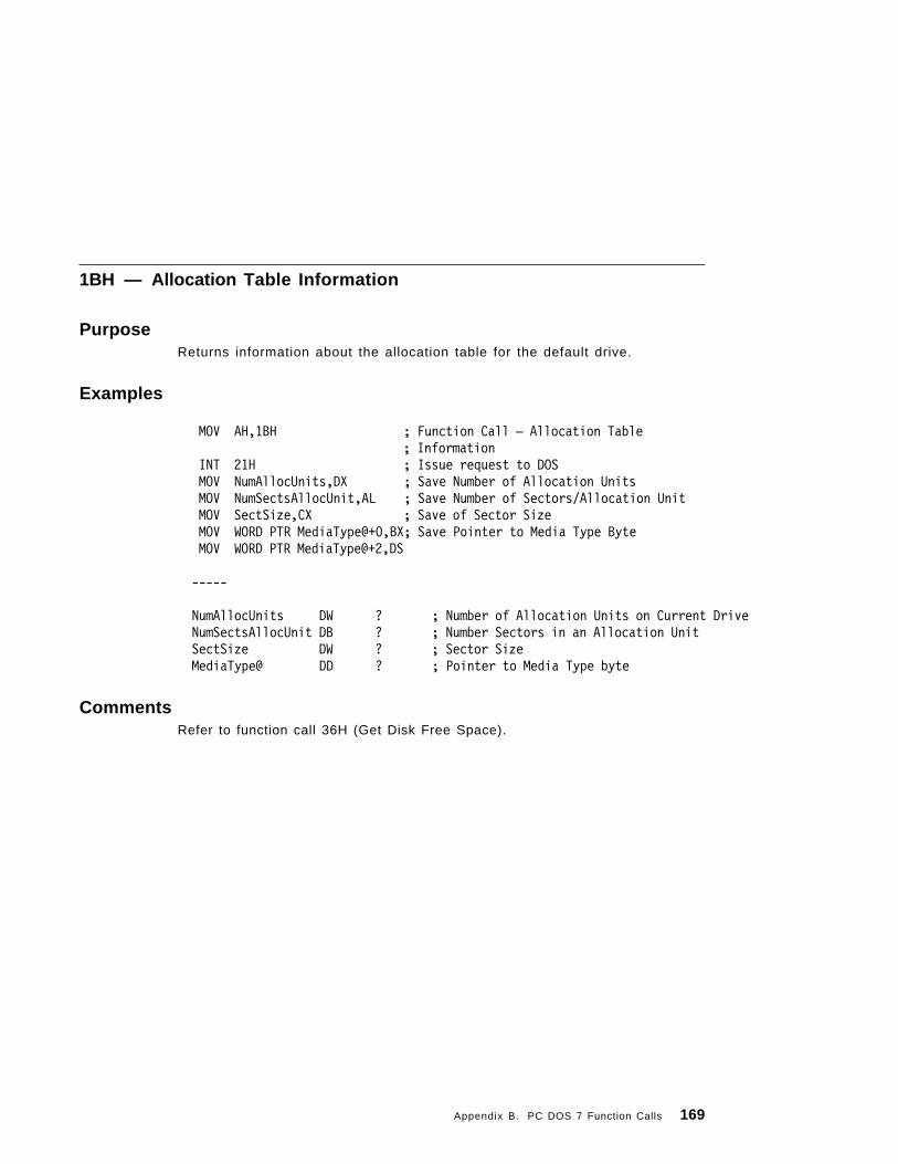
1BH — Allocation Table Information
PurposeReturns information about the allocation table for the default drive.
Examples
MOV AH,1BH ; Function Call — Allocation Table; Information
INT 21H ; Issue request to DOSMOV NumAllocUnits,DX ; Save Number of Allocation UnitsMOV NumSectsAllocUnit,AL ; Save Number of Sectors/Allocation UnitMOV SectSize,CX ; Save of Sector SizeMOV WORD PTR MediaType@+0,BX; Save Pointer to Media Type ByteMOV WORD PTR MediaType@+2,DS
-----
NumAllocUnits DW ? ; Number of Allocation Units on Current DriveNumSectsAllocUnit DB ? ; Number Sectors in an Allocation UnitSectSize DW ? ; Sector SizeMediaType@ DD ? ; Pointer to Media Type byte
CommentsRefer to function call 36H (Get Disk Free Space).
Appendix B. PC DOS 7 Function Calls 169

1CH — Allocation Table Information for Specific Device
PurposeReturns allocation table information for a specific device.
Examples MOV AH,1CH ; Function Call —
; Allocation Table Information MOV DL,Drive ; Drive requested (0=current,
; 1=A:, ...) INT 21H ; Issue request to DOS MOV NumAllocUnits,DX ; Save Number of Allocation Units MOV NumSectsAllocUnit,AL ; Save Number of Sectors/Allocation Unit MOV SectSize,CX ; Save of Sector Size MOV WORD PTR MediaType@+0,BX ; Save Pointer to Media Type Byte MOV WORD PTR MediaType@+2,DS
-----Drive DB ; drive number to get info forNumAllocUnits DW ? ; Number of Allocation Units
; on specified driveNumSectsAllocUnit DB ? ; Number Sectors in an
; Allocation UnitSectSize DW ? ; Sector SizeMediaType@ DD ? ; Pointer to Media Type byte
CommentsThis call is the same as call 1BH, except that on entry DL contains thenumber of the drive that contains the needed information (0 = default, 1 =A, and so forth). For more information on PC DOS 7 disk allocation, refer to“The Disk Directory” on page 11. Also, refer to function call 36H (Get DiskFree Space).
170 PC DOS 7
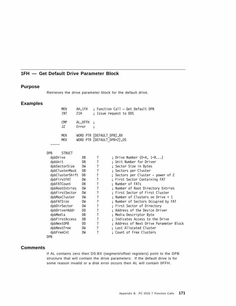
1FH — Get Default Drive Parameter Block
PurposeRetrieves the drive parameter block for the default drive.
ExamplesMOV AH,1FH ; Function Call — Get Default DPBINT 21H ; Issue request to DOS
CMP AL,0FFH ;JZ Error ;
MOV WORD PTR [DEFAULT_DPB],BXMOV WORD PTR [DEFAULT_DPB+2],DS
-----
DPB STRUCTdpbDrive DB ? ; Drive Number (0=A, 1=B...)dpbUnit DB ? ; Unit Number for DriverdpbSectorSize DW ? ; Sector Size in BytesdpbClusterMask DB ? ; Sectors per Cluster
dpbClusterShift DB ? ; Sectors per Cluster - power of 2dpbFirstFAT DW ? ; First Sector Containing FATdpbFATCount DB ? ; Number of FATsdpbRootEntries DW ? ; Number of Root Directory EntriesdpbFirstSector DW ? ; First Sector of First ClusterdpbMaxCluster DW ? ; Number of Clusters on Drive + 1dpbFATSize DW ? ; Number of Sectors Occupied by FATdpbDirSector DW ? ; First Sector of DirectorydpbDriverAddr DD ? ; Address of the Device DriverdpbMedia DB ? ; Media Descriptor BytedpbFirstAccess DB ? ; Indicates Access to the DrivedpbNextDPB DD ? ; Address of Next Drive Parameter BlockdpbNextFree DW ? ; Last Allocated ClusterdpbFreeCnt DW ? ; Count of Free Clusters
DPB
CommentsIf AL contains zero then DS:BX (segment/offset registers) point to the DPBstructure that will contain the drive parameters. If the default drive is forsome reason invalid or a disk error occurs then AL will contain 0FFH.
Appendix B. PC DOS 7 Function Calls 171

21H — Random Read
PurposeReads the record addressed by the current block and current record fieldsinto memory at the current disk transfer address.
Examples;Set up FCB
MOV AX,SEG DTA ;Address Data bufferMOV DS,AXMOV DX,OFFSET DTAMOV AH,1AH ;Function Set DTA AddressINT 21H ;Issue request to DOSMOV AX,SEG FCB ;Address FCB Parameter BlockMOV DS,AXMOV DX,OFFSET FCBMOV AH,21H ;Function Call-FCB Random ReadINT 21H ;Issue request to DOS
CMP AL,0 ;Data Read? JNE Error ;No, Error!-----FCB LABEL BYTE; Set by previous open; DTA label byte
CommentsAL is 00H if the read was successful.
AL is 01H if the file was at End of File (EOF) (no data read).
AL is 02H if the read would have caused a wrap or overflow because the DTAwas too small (the read was not completed).
AL is 03H if EOF (a partial record was read and filled out with 0′s).
Use Function Call 59H (Get Extended Error) to determine the actual errorcondition. The current block and current record fields are set to agree withthe random record field. The record addressed by these fields is read intomemory at the current disk transfer address. For information on record sizesee Chapter 4, “Accessing Files Using File Control Blocks” on page 23.
Note: Function 24H must be called before using this function.
Network Access Rights: Requires Read access rights.
172 PC DOS 7

22H — Random Write
PurposeWrites the record addressed by the current block and current record fieldsfrom the current disk transfer address.
Examples;Set up FCB
MOV AX,SEG FCB ;Address FCB parameter blockMOV DS,AXMOV DX,OFFSET FCBMOV AH,24H ;Function Call—FCB Set
;Relative record fieldINT 21H ;Issue request to DOSMOV AX,SEG DTA ;Address data bufferMOV DS,AXMOV DX,OFFSET DTAMOV AH,1AH ;Function Set DTA addressINT 21H ;Issue request to DOSMOV AX,SEG FCB ;Address FCB parameter blockMOV DS,AXMOV DX,OFFSET FCBMOV AH,22H ;Function Call-FCB random writersINT 21H ;Issue request to DOSCMP AL,0 ;Data written?JNE Error ;No, error!
-----
FCB LABEL BYTE; Set by previous openDTA LABEL BYTE
CommentsAL is 00H if the write was successful.
AL is 01H if the write or diskette is full (write cancelled).
AL is 02H if the read would have caused a wrap or overflow because the DTAwas too small (write cancelled).
Use Function Call 59H (Get Extended Error) to determine the actual errorcondition.
Appendix B. PC DOS 7 Function Calls 173

The current block and current record fields are set to agree with the randomrecord field. Then the record addressed by these fields is written (or in thecase of records not the same as sector sizes — buffered) from the disktransfer address.
If the file is specified in read-only mode, the random write is not performed.
Network Access Rights: Requires Write access rights.
174 PC DOS 7

23H — File Size
PurposeSearches the current directory for an entry that matches the specified fileand sets the FCBs random record field to the number of records in the file.
ExamplesMOV AX,SEG FCB ; Address FCB parameter blockMOV DS,AXMOV DX,OFFSET FCBMOV AH,23H ; Function Call-FCB file sizeINT 21H ; Issue request to DOSCMP AL,0 ; File found?JNE Error ; No, error!
-----
FCB LABEL BYTEDrive DB 0 ; Drive (0=Current, 1=A, 2=B, ...)Name DB ″FILENAME″ ; File name (blank padded)Ext DB ″EXT″ ; File extension (blank padded)
DB 25 DUP(0) ; Filled in by DOS
CommentsAL is 00H if the file exists.
AL is FFH if the file was not created (normally a full directory or disk full).
Use Function Call 59H (Get Extended Error) to determine the actual errorcondition.
The directory is searched for the matching entry. If a matching entry isfound, the random record field is set to the number of records in the file (interms of the record size field rounded up). If no matching entry is found, ALreturns FFH.
Note: If you do not set the FCB record size field before using this function,incorrect information is returned.
Appendix B. PC DOS 7 Function Calls 175

24H — Set Relative Record Field
PurposeSets the random record field to the same file address as the current blockand record fields.
Examples MOV AX,SEG FCB ;Address FCB parameter block MOV DS,AX MOV DX,OFFSET FCB MOV AH,24H ;Function Call—FCB set
;Relative record field INT 21H ;Issue request to DOS
-----
FCB LABEL BYTE; Set by previous open
CommentsYou must call this function before you perform random reads and writes, andrandom block reads and writes.
176 PC DOS 7
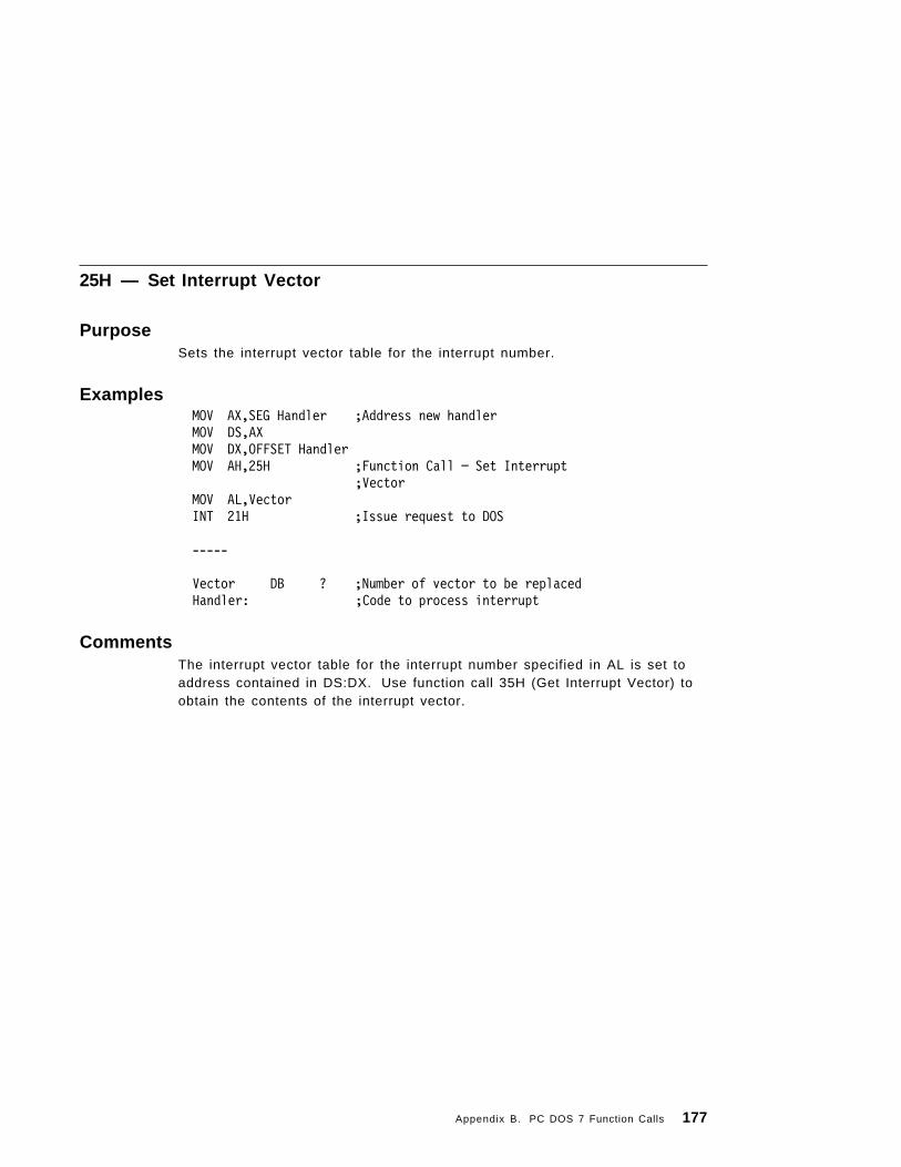
25H — Set Interrupt Vector
PurposeSets the interrupt vector table for the interrupt number.
Examples MOV AX,SEG Handler ;Address new handler MOV DS,AX MOV DX,OFFSET Handler MOV AH,25H ;Function Call − Set Interrupt
;Vector MOV AL,Vector INT 21H ;Issue request to DOS
-----
Vector DB ? ;Number of vector to be replacedHandler: ;Code to process interrupt
CommentsThe interrupt vector table for the interrupt number specified in AL is set toaddress contained in DS:DX. Use function call 35H (Get Interrupt Vector) toobtain the contents of the interrupt vector.
Appendix B. PC DOS 7 Function Calls 177

26H — Create New Program Segment
PurposeCreates a new program segment.
ExamplesMOV AH,26H ; Function Call — Create Program
; SegmentMOV DX,SEG PSP ; Segment address to create new PSPINT 21H ; Issue request to DOS
-----
PSP LABEL BYTE ; Area to fill inDB 100H DUP(0)
CommentsThe entire 100H area at location 0 in the current program segment is copiedinto location 0 in the new program segment. The memory size information atlocation 6 in the new segment is updated and the current termination,Ctrl-Break exit and critical error addresses from interrupt vector table entriesfor interrupts 22H, 23H, and 24H are saved in the new program segmentstarting at 0AH. They are restored from this area when the program ends.
Note: The EXEC function call 4BH provides a more complete service.Therefore, you should use the EXEC 4BH and avoid using this call.
178 PC DOS 7
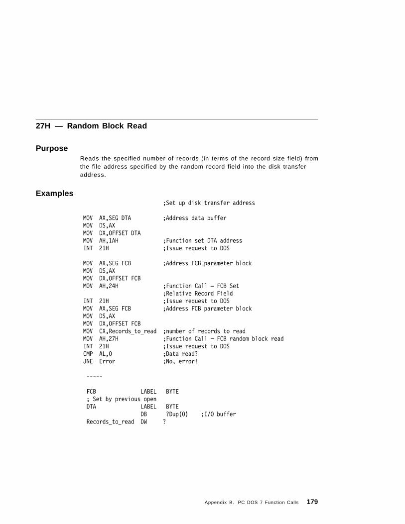
27H — Random Block Read
PurposeReads the specified number of records (in terms of the record size field) fromthe file address specified by the random record field into the disk transferaddress.
Examples;Set up disk transfer address
MOV AX,SEG DTA ;Address data buffer MOV DS,AX MOV DX,OFFSET DTA MOV AH,1AH ;Function set DTA address INT 21H ;Issue request to DOS
MOV AX,SEG FCB ;Address FCB parameter block MOV DS,AX MOV DX,OFFSET FCB MOV AH,24H ;Function Call — FCB Set
;Relative Record Field INT 21H ;Issue request to DOS MOV AX,SEG FCB ;Address FCB parameter block MOV DS,AX MOV DX,OFFSET FCB MOV CX,Records to read ;number of records to read MOV AH,27H ;Function Call − FCB random block read INT 21H ;Issue request to DOS CMP AL,0 ;Data read? JNE Error ;No, error!
-----
FCB LABEL BYTE; Set by previous openDTA LABEL BYTE
DB ?Dup(0) ;I/O bufferRecords to read DW ?
Appendix B. PC DOS 7 Function Calls 179

CommentsAL is 00H if the read was successful.
AL is 01H if the file was at End of File (EOF) (no data read).
AL is 02H if the read would have caused a wrap or overflow because the DTAwas too small (the read was not completed).
AL is 03H if EOF (a partial record was read and filled out with zeros).
Use Function Call 59H (Get Extended Error) to determine the actual errorcondition.
The random record field and the current block/record fields are set toaddress the next record (the first record not read).
Note: Function 24H must be called before using this function.
Network Access Rights: Requires Read access rights.
180 PC DOS 7

28H — Random Block Write
PurposeWrites the specified number of records from the disk transfer address intothe file address specified by the random record field.
Examples;Set up disk transfer address
MOV AX,SEG DTA ;Address data bufferMOV DS,AXMOV DX,OFFSET DTAMOV AH,1AH ;Function set DTA addressINT 21H ;Issue request to DOS
MOV AX,SEG FCB ;Address FCB parameter blockMOV DS,AXMOV DX,OFFSET FCBMOV AH,24H ;Function Call—FCB set
;Relative record fieldINT 21H ;Issue request to DOS
MOV AX,SEG FCB ;Address FCB parameter blockMOV DS,AXMOV DX,OFFSET FCBMOV CX,Records to write ;Number of records to writeMOV AH,28H ;Function Call − FCB Random Block writeINT 21H ;Issue request to DOSCMP AL,0 ;Data written?JNE Error ;No, error!
-----
DTA LABEL BYTE
DB ?DUP(0) ; I/O Buffer
CommentsAL is 00H if the write was successful.
AL is 01H if the disk or diskette is full (write cancelled).
AL is 02H if the write would have caused a wrap or overflow because theDTA was too small (write cancelled).
Appendix B. PC DOS 7 Function Calls 181

Use Function Call 59H (Get Extended Error) to determine the actual errorcondition.
If there is insufficient space on the disk, AL returns 01H and no records arewritten. If CX is 0 upon entry, no records are written, but the file is set to thelength specified by the random record field, whether longer or shorter thanthe current file size. (Allocation units are released or allocated asappropriate.)
Note: Function call 24H must be called before using this function.
Network Access Rights: Requires Write access rights.
182 PC DOS 7

29H — Parse Filename
PurposeParses the specified filename.
ExamplesMOV AX,SEG CmdBufMOV DS,AX ;Address command stringMOV SI,OFFSET CmdBufMOV AX,SEG FCBMOV ES,AX ;Address FCB Parameter BlockMOV DI,OFFSET FCBMOV AH,29H ;Function Call - FCB Parse FilenameMOV AL,OPTIONS ;Set desired actionINT 21H ;Issue request to DOS
CMP AL,-1 ;Drive valid?JE Error ;No, Error!-----
CmdBuf LABEL BYTEDB ″ a:file.ext ″,0DH
FCB LABEL BYTE; Created in a pre-open state based on input found.Options DB ? ;parsing options
CommentsThe contents of AL are used to determine the action to take, as shown below:
< m u s t = 0 >bit: 7 6 5 4 3 2 1 0
If bit 0 = 1, leading separators are scanned off the command line at DS:SI.Otherwise, no scan-off of leading separators takes place.
If bit 1 = 1, the drive ID byte in the FCB will be set (changed) only if a drivewas specified in the command line being parsed.
If bit 2 = 1, the filename in the FCB will be changed only if the command linecontains a filename.
If bit 3 = 1, the filename extension in the FCB will be changed only if thecommand line contains a filename extension.
Appendix B. PC DOS 7 Function Calls 183

Filename separators include the following characters:
: . : , = + along with TAB and SPACE. Filename terminators include all ofthese characters plus , < , > , | , /, ″, [, ], and any control characters.
Output:
AL is 00H if no global characters (? or *) were found in the Command String.
AL is 01H if global characters (? or *) were found in the Command String.
AL is FFH if the drive specified is invalid.
The command line is parsed for a filename of the form d:filename.ext, and iffound, a corresponding unopened FCB is created at ES:DI. If no drivespecifier is present, it is assumed to be all blanks. If the character * appearsin the filename or extension, it and all remaining characters in the name orextension are set to ?.
DS:SI returns pointing to the first character after the filename and ES:DIpoints to the first byte of the formatted FCB. If no valid filename is present,ES:DI+1 contains a blank.
184 PC DOS 7

2AH — Get Date
PurposeReturns the day of the week, the year, month and date.
ExamplesMOV AH,2AH ; Function Call — Get DateINT 21H ; Issue request to DOSMOV DayofWeek,AL ; Save Day of the WeekMOV Year,CX ; Save YearMOV Month,DH ; Save MonthMOV Day,DL ; Save Day
-----
DayofWeek DB ? ; 0=Sunday, ... 6=SaturdayYear DW ? ; 1980 to 2099Month DB ? ; 1 to 12Day DB ? ; 1 to 31
CommentsIf the time-of-day clock rolls over to the next day, the date is adjustedaccordingly, taking into account the number of days in each month and leapyears.
Appendix B. PC DOS 7 Function Calls 185
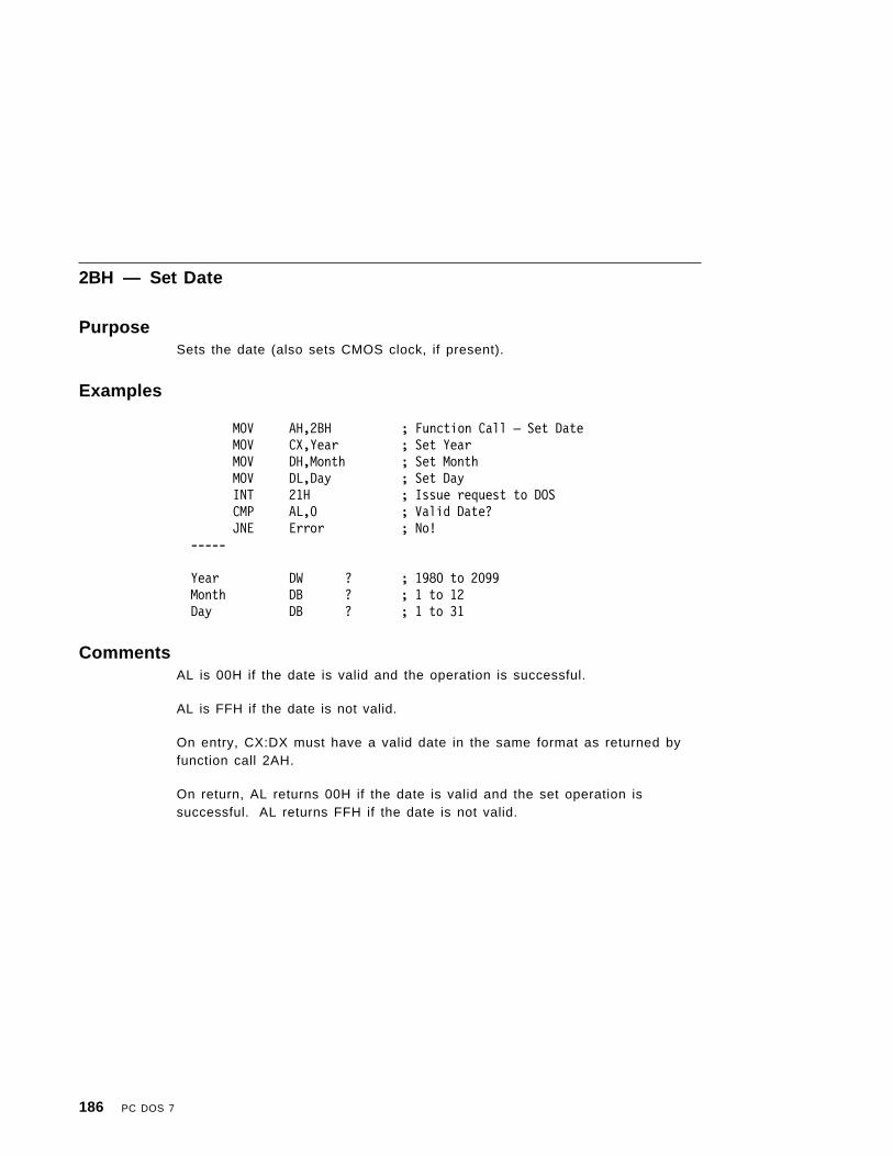
2BH — Set Date
PurposeSets the date (also sets CMOS clock, if present).
Examples
MOV AH,2BH ; Function Call — Set DateMOV CX,Year ; Set YearMOV DH,Month ; Set MonthMOV DL,Day ; Set DayINT 21H ; Issue request to DOSCMP AL,0 ; Valid Date?JNE Error ; No!
-----
Year DW ? ; 1980 to 2099Month DB ? ; 1 to 12Day DB ? ; 1 to 31
CommentsAL is 00H if the date is valid and the operation is successful.
AL is FFH if the date is not valid.
On entry, CX:DX must have a valid date in the same format as returned byfunction call 2AH.
On return, AL returns 00H if the date is valid and the set operation issuccessful. AL returns FFH if the date is not valid.
186 PC DOS 7

2CH — Get Time
PurposeReturns the time; hours, minutes, seconds and hundredths of seconds.
Examples
MOV AH,2CH ; Function Call — ; Get Time
INT 21H ; Issue request to DOSMOV Hour,CH ; Save HourMOV Minute,CL ; Save MinuteMOV Second,DH ; Save SecondMOV Hundredth,DL ; Save Partial Second
-----
Hour DB ? ; 0 to 23Minute DB ? ; 0 to 59Second DB ? ; 0 to 59Hundredth DB ? ; 0 to 99
CommentsOn entry, AH contains 2CH. On return, CX:DX contains the time-of-day. Timeis actually represented as four 8-bit binary quantities as follows:
CH Hours (0− 2 3 )CL Minutes (0− 5 9 )DH Seconds (0− 5 9 )DL 1/100 seconds (0− 9 9 ) .
This format is readily converted to a printable form yet can also be used forcalculations, such as subtracting one time value from another.
Appendix B. PC DOS 7 Function Calls 187
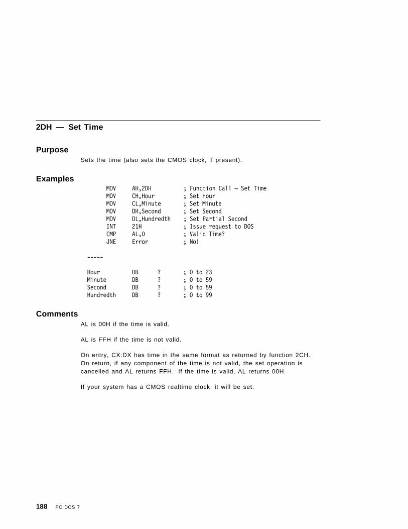
2DH — Set Time
PurposeSets the time (also sets the CMOS clock, if present).
ExamplesMOV AH,2DH ; Function Call — Set TimeMOV CH,Hour ; Set HourMOV CL,Minute ; Set MinuteMOV DH,Second ; Set SecondMOV DL,Hundredth ; Set Partial SecondINT 21H ; Issue request to DOSCMP AL,0 ; Valid Time?JNE Error ; No!
-----
Hour DB ? ; 0 to 23Minute DB ? ; 0 to 59Second DB ? ; 0 to 59Hundredth DB ? ; 0 to 99
CommentsAL is 00H if the time is valid.
AL is FFH if the time is not valid.
On entry, CX:DX has time in the same format as returned by function 2CH.On return, if any component of the time is not valid, the set operation iscancelled and AL returns FFH. If the time is valid, AL returns 00H.
If your system has a CMOS realtime clock, it will be set.
188 PC DOS 7

2EH — Set/Reset Verify Switch
PurposeSets the verify switch.
Examples; To set VERIFY=OFF
MOV AH,2EH ; Function Call — Set; VERIFY
MOV AL,0 ; Set OFFINT 21H ; Issue request to DOS
; To set VERIFY=ON
MOV AH,2EH ; Function Call — Set; VERIFY
MOV AL,1 ; Set ONINT 21H ; Issue request to DOS
CommentsOn entry, AL must contain 01H to turn verify on, or 00H to turn verify off.When verify is on, PC DOS 7 performs a verify operation each time itperforms a disk write to assure proper data recording. Although diskrecording errors are very rare, this function has been provided forapplications in which you may wish to verify the proper recording of criticaldata. You can obtain the current setting of the verify switch through functioncall 54H.
Note: Verification is not supported on data written to a network disk.
Appendix B. PC DOS 7 Function Calls 189

2FH — Get Disk Transfer Address (DTA)
PurposeReturns the current disk transfer address.
ExamplesMOV AH,2FH ; Function Call — Get
; DTA AddressINT 21H ; Issue request to DOSMOV WORD PTR DTA@+0,BX ; Save AddressMOV WORD PTR DTA@+2,ES
-----
DTA@ DD ? ; DTA Buffer
CommentsOn entry, AH contains 2FH. On return, ES:BX contains the current DiskTransfer Address. You can set the DTA using function call 1AH.
190 PC DOS 7

30H — Get DOS Version Number
PurposeReturns the DOS version number.
ExamplesPUSH CX ; CX destroyed in callPUSH BXMOV AH,30H ; Function Call — Get PC DOS 7
; VersionINT 21H ; Issue request to DOSMOV MajorVersion,AL ; Save VersionMOV MinorVersion,AHMOV DOS_Running_From,BH ;POP BXPOP CX
-----MajorVersion DB ? ; X of X.YYMinorVersion DB ? ; YY of X.YYDOS_Running_From DB ? ; 0 = DOS not running in ROMDOS_Running_From DB ? ; 8 = DOS running in ROM
CommentsOn entry, AH contains 30H. On return, CX is set to 0. AL contains the majorversion number. AH contains the minor version number. BH contains 8 or 0for DOS running or not running in ROM.
If AL returns a major version number of 0, you can assume that the DOSversion is pre-DOS 2.00.
Use function call 33H AL=6 (Get or Set System Value) to get the true versionnumber.
Appendix B. PC DOS 7 Function Calls 191

31H — Terminate Process and Remain Resident
PurposeTerminates the current process and attempts to set the initial allocation blockto the memory size in paragraphs.
ExamplesMOV AH,31H ; Function Call — Terminate
; and Keep ProcessMOV AL,RetCode ; Set value of ERRORLEVELMOV DX,MySize ; Set my program and data sizeINT 21H ; Issue request to DOSINT 20H ; Be safe if on DOS Version 1.X
-----
RetCode DB ? ; Value to return to my EXEC′ erMySize DW ? ; Size of my code and data
; (in paragraphs)
CommentsOn entry, AL contains a binary return code. DX contains the memory sizevalue in paragraphs. This function call does not free up any other allocationblocks belonging to that process. Files opened by the process are not closedwhen the call is executed. The return code passed in AL is retrievable bythe parent through Wait (function call 4DH) and can be tested through theERRORLEVEL batch subcommands.
Memory is used efficiently if the block containing a copy of the environmentis deallocated before terminating. This can be done by loading ES with thesegment contained in 2C of the PSP, and issuing function call 49H (FreeAllocated Memory). The five standard handles, 0000 through 0004, should beclosed before exiting.
192 PC DOS 7

32H — Get Drive Parameter Block
PurposeRetrieves the drive parameter block for the specified drive.
ExamplesMOV DL,DRIVE_NUM ; Drive Number (0=Default, 1=A, 2=B...)MOV AH,32H ; Function Call — Get DPBINT 21H ; Issue request to DOS
CMP AL,0FFH ;JZ Error ;
MOV WORD PTR [SPECIFIED_DPB],BXMOV WORD PTR [SPECIFIED_DPB+2],DS
-----DPB STRUCTdpbDrive DB ? ; Drive Number (0=A, 1=B...)dpbUnit DB ? ; Unit Number for DriverdpbSectorSize DW ? ; Sector Size in BytesdpbClusterMask DB ? ; Sectors per Cluster
dpbClusterShift DB ? ; Sectors per Cluster - power of 2dpbFirstFAT DW ? ; First Sector Containing FATdpbFATCount DB ? ; Number of FATsdpbRootEntries DW ? ; Number of Root Directory EntriesdpbFirstSector DW ? ; First Sector of First ClusterdpbMaxCluster DW ? ; Number of Clusters on Drive + 1dpbFATSize DW ? ; Number of Sectors Occupied by FATdpbDirSector DW ? ; First Sector of DirectorydpbDriverAddr DD ? ; Address of the Device DriverdpbMedia DB ? ; Media Descriptor BytedpbFirstAccess DB ? ; Indicates Access to the DrivedpbNextDPB DD ? ; Address of Next Drive Parameter BlockdpbNextFree DW ? ; Last Allocated ClusterdpbFreeCnt DW ? ; Count of Free Clusters
DPB
Appendix B. PC DOS 7 Function Calls 193
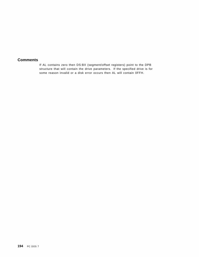
CommentsIf AL contains zero then DS:BX (segment/offset registers) point to the DPBstructure that will contain the drive parameters. If the specified drive is forsome reason invalid or a disk error occurs then AL will contain 0FFH.
194 PC DOS 7

33H — Get or Set System Value
PurposeSet or get the state of System Values such as BREAK (Ctrl-Break checking).
Examples; To check BREAK state
MOV AH,33H ; Function Call — Get/Set; System value
MOV AL,0 ; Do Get BREAKINT 21H ; Issue request to DOSMOV BREAK,DL ; Save state (00=OFF, 01H=ON)
; To set BREAK=OFF
MOV AH,33H ; Function Call — Get/Set; System value
MOV AL,1 ; Do Set BREAKMOV DL,0 ; Set OFFINT 21H ; Issue request to DOS
; To set BREAK=ON
MOV AH,33H ; Function Call — Get/Set; System Value
MOV AL,1 ; Do Set BREAKMOV DL,1 ; Set ONINT 21H ; Issue request to DOS
; To get the Boot Drive
MOV AH,33H ; Function Call — Get/Set; System Value
MOV AL,5 ; Do Get Boot DriveINT 21H ; Issue request to DOSMOV Drive,DL ; Save boot drive
; To get the True Version Number
MOV AH,33H ; Function Call — Get/Set; System Value
MOV AL,6 ; Get True VersionINT 21H ; Issue request to DOSMOV MajorVersion,BL
Appendix B. PC DOS 7 Function Calls 195
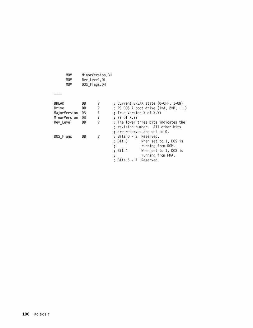
MOV MinorVersion,BHMOV Rev_Level,DLMOV DOS_Flags,DH
----
BREAK DB ? ; Current BREAK state (0=OFF, 1=ON)Drive DB ? ; PC DOS 7 boot drive (1=A, 2=B, ...)
MajorVersion DB ? ; True Version X of X.YY MinorVersion DB ? ; YY of X.YYRev_Level DB ? ; The lower three bits indicates the
; revision number. All other bits; are reserved and set to 0.
DOS_Flags DB ? ; Bits 0 - 2 Reserved.; Bit 3 When set to 1, DOS is; running from ROM.; Bit 4 When set to 1, DOS is; running from HMA.; Bits 5 - 7 Reserved.
196 PC DOS 7

34H — Get InDOS Flag Address
PurposeReturns the address of the PC DOS 7 InDOS flag. The InDOS flag shows thecurrent state of Interrupt 21H processing.
ExamplesMOV AH,34H ; Function Call — Get InDOS Flag AddressINT 21H ; Issue request to DOS
MOV InDOS,BYTE PTR ES:[BX]
CommentsWhile PC DOS 7 is processing one of the Interrupt 21H functions, the value ofthe InDOS flag will be nonzero.
The ES:BX (segment/offset) register pair will contain the InDOS flag address.
Appendix B. PC DOS 7 Function Calls 197

35H — Get Interrupt Vector
PurposeTo obtain the address in an interrupt vector.
ExamplesMOV AH,35H ; Function Call —
; Set Interrupt VectorMOV AL,Vector ; Vector to get (0 to 255)INT 21H ; Issue request to DOSMOV WORD PTR OldVect+0,BXMOV WORD PTR OldVect+2,ES
-----
OldVect DD ? ; Previous vector contentsVector DB ? ; Vector number to get
CommentsOn return, ES:BX contains the CS:IP interrupt vector for the specifiedinterrupt. Use function call 25H (Set Interrupt Vector) to set the interruptvectors.
198 PC DOS 7

36H — Get Disk Free Space
PurposeReturns the disk free space (available clusters, clusters/drive, bytes/sector).
ExamplesMOV AH,36H ; Function Call —
; Get disk free spaceMOV DL,Drive ; Drive to query
; (0=current, 1=A:,; 2=B:, ...)
INT 21H ; Issue request to DOSCMP AX,-1 ; Error?JE Error ; YesMOV SectAU,AX ; Save allocation unit
; SizeMOV AvailAU,BX ; Save free allocation
; UnitsMOV SectSize,CX ; Save sector sizeMOV TotalAU,DX ; Save disk size
MOV AX,SectSize ; Calculate allocation; Unit size
MUL SectAUMOV CX,AX ; CX = bytes/AUMOV AX,TotalAU ; Calculate total spaceMUL CXMOV WORD PTR TotalBytes+0,AX ; Save itMOV WORD PTR TotalBytes+2,DXMOV AX,AvailAU ; Calculate free spaceMUL CXMOV WORD PTR FreeBytes+0,AX ; Save itMOV WORD PTR FreeBytes+2,DX
-----
SectAU DW ? ; Sectors in an; Allocation unit
AvailAU DW ? ; Free allocation unitsSectSize DW ? ; Bytes in a sectorTotalAU DW ? ; Number of allocation
; Units on DL diskTotalBytes DD ? ; Disk size in bytesFreeBytes DD ? ; Free space in bytesDrive DD ? ; Drive number to get info for
Appendix B. PC DOS 7 Function Calls 199
CommentsIf the drive number in DL was valid, BX contains the number of availableallocation units, DX contains the total number of allocation units on the drive,CX contains the number of bytes per sector, and AX contains the number ofsectors for each allocation unit.
200 PC DOS 7

38H — Get or Set Country Dependent Information
PurposeSets the Active Country or returns country dependent information.
Examples; To set the Current Country
MOV AH,38H ; Function Call — Get/Set; Country Information
MOV AL,CountryID ; Country ID (-1 if >= 255)MOV BX,CountryIDX ; Country ID (if AL=-1)MOV DX,-1 ; Indicate set country codeINT 21H ; Issue request to DOSJC Error ; Error code in AX
; To get Country Information
MOV AX,SEG BufferMOV DS,AXMOV DX,OFFSET BufferMOV AH,38HMOV AL,CountryID ; Country ID (-1 if >= 255)
; (0 to get current country)MOV BX,CountryIDX ; Country ID (if AL=-1)
INT 21H ; Issue request to DOSJC Error ; Error code in AXMOV CountryCode,BX ; Save current Country Code
----
CountryCode DW ? ; Current country code
CountryIDX DW ? ; Extended country code for input
Buffer LABEL WORD ; Country information (see format below)CountryID DB ? ; Country code for input
Appendix B. PC DOS 7 Function Calls 201

Country Information
DateFormat DW ? ; Date Format:; 0 = m d y order; 1 = d m y order; 2 = y m d order
$Symbol DB ″????″,0 ; Currency Symbol; example: ″DM″ ,0 ,? , ?
Sep1000 DB ″?″,0 ; Thousands Separator; example: ″ , ″ ,0
Sep1 DB ″?″,0 ; Fractions Separator; example: ″ . ″ ,0
SepDate DB ″?″,0 ; Date Separator; example: ″ /″ ,0
SepTime DB ″?″,0 ; Time Separator; example: ″ :″ ,0
$Format DB ? ; Currency Format:; 0 = currency symbol, value; 1 = value, currency symbol; 2 = currency symbol, space, value; 3 = value, space, currency symbol; 4 = currency symbol is decimal separator
SigDigits DB ? ; Number of Significant Digits in CurrencyTimeFormat DB ? ; Time Format:
; 0 = 12 hour clock; 1 = 24 hour clock
UpperCaseAL@ DD ? ; Address of Routine to Upper Case AL; Only for values >=80H
SepData DB ″?″,0 ; Data List Separator; example: ″ , ″ ,0
Reserved DW 5 DUP(?) ; Reserved for future
CommentsThe date format has the following values and meaning:
Code Date0=USA m d y1=Europe d m y2=Japan y m d
Case Map Call Address: The register contents for the case map call are:
OnEntry
RegisterContents
AL ASCII code of character to be converted to uppercase
202 PC DOS 7

The case map call address is in a form suitable for a FAR call indirect.
OnReturn
RegisterContents
AL ASCII code of the uppercase input character
ResultsError codes are returned in AX. Issue function call 59H (Get Extended Error)for additional information about the error class, suggested action, andlocation. Function Call 65H (Get Extended Country Information) returns morecountry information and is preferred.
Setting the Current County Code by using this function call is notrecommended. The user can set it by placing a COUNTRY command in theCONFIG.SYS file. The Country Code set by the user should not be changed.The NLSFUNC PC DOS 7 extension must be installed to change the CurrentCountry.
Appendix B. PC DOS 7 Function Calls 203

39H — Create Subdirectory (MKDIR)
PurposeCreates the specified directory.
ExamplesMOV AX,SEG DName ;Directory NameMOV DS,AXMOV DX,OFFSET DName MOV AH,39H ;Function-Make a directory INT 21H ;Issue request to DOS JC Error
----
DName DB ″?? .. ??″,0 ; ASCIIZ Name; Example:; ″c:\dir″,0
CommentsOn entry, DS:DX contains the address of an ASCIIZ string with drive anddirectory path names. All directory levels other than the last one in thename must exist before using this function. Only one directory level at atime can be created with this function. The maximum length of the ASCIIZstring is 64 characters.
Error codes are returned in AX. Issue function call 59H (Get Extended Error)for additional information about the error class, suggested action, andlocation.
Network Access Rights: Requires Create access rights.
204 PC DOS 7

3AH — Remove Subdirectory (RMDIR)
PurposeRemoves the specified directory.
ExamplesMOV AX,SEG DName ;Directory nameMOV DS,AXMOV DX,OFFSET DNameMOV AH,3AH ;Function-Remove directory INT 21H ;Issue request to DOS JC Error
----
DName DB ″?? .. ??″,0 ; ASCIIZ Name; example: ″c:\dir″,0
CommentsOn entry, DS:DX contains the address of an ASCIIZ string with the drive anddirectory path names. The specified directory is removed from the structure.The current directory or a directory with files in it cannot be removed.
Error codes are returned in AX. Issue function call 59H (Get Extended Error)for additional information about the error class, suggested action, andlocation.
Network Access Rights: Requires Create access rights.
Appendix B. PC DOS 7 Function Calls 205
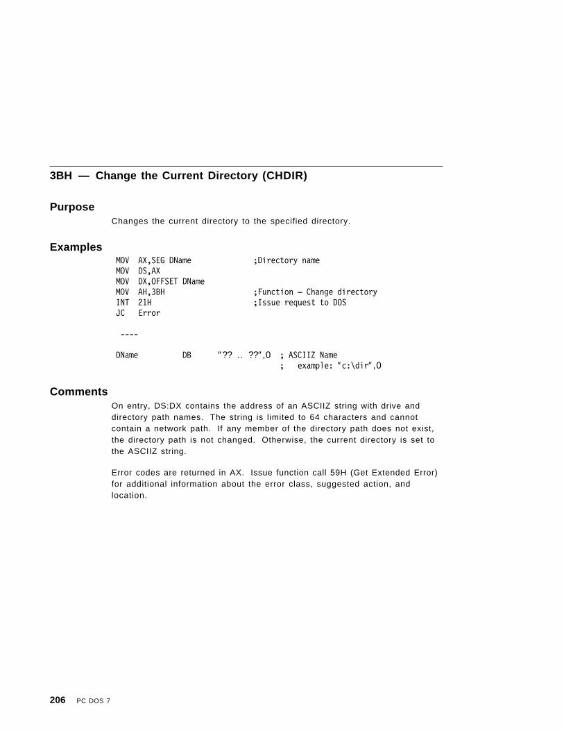
3BH — Change the Current Directory (CHDIR)
PurposeChanges the current directory to the specified directory.
ExamplesMOV AX,SEG DName ;Directory nameMOV DS,AXMOV DX,OFFSET DName MOV AH,3BH ;Function — Change directory INT 21H ;Issue request to DOS JC Error
----
DName DB ″?? .. ??″,0 ; ASCIIZ Name; example: ″c:\dir″,0
CommentsOn entry, DS:DX contains the address of an ASCIIZ string with drive anddirectory path names. The string is limited to 64 characters and cannotcontain a network path. If any member of the directory path does not exist,the directory path is not changed. Otherwise, the current directory is set tothe ASCIIZ string.
Error codes are returned in AX. Issue function call 59H (Get Extended Error)for additional information about the error class, suggested action, andlocation.
206 PC DOS 7

3CH — Create a File
PurposeCreates a new file or shortens an old file to 0 length in preparation forwriting.
ExamplesMOV AX,SEG FName ;File nameMOV DS,AXMOV DX,OFFSET FNameMOV AH,3CH ;Function — Create a FileMOV CX,Attribute ; Attribute of the file
; Allowed values; 0001H=Read only; 0002H=Hidden; 0004H=System; 0008H=Volume label
INT 21H ; Issue request to DOSJC Error ; Error code in AXMOV Handle,AX ; Save file handle for
----
FName DB ″?? .. ??″,0 ; ASCIIZ Name; example: ″c:\dir\file.ext″,0
Handle DW ? ; File handleAttribute DW ? ; Attributes for directory entry
CommentsIf the file did not exist, the file is created in the appropriate directory and thefile is given the read/write access code. The file is opened for read/write,the read/write pointer is set to the first byte of the file and the handle isreturned in AX. Note that function call 43H (Change File Mode) can be usedlater to change the attribute of the file.
Error codes are returned in AX. Issue function call 59H (Get Extended Error)for additional information about the error class, suggested action, andlocation.
This function does not replace an existing volume label. You must delete theexisting volume label before issuing this call.
Network Access Rights: Requires Create access rights.
Appendix B. PC DOS 7 Function Calls 207

3DH — Open a File
PurposeOpens the specified file.
Examples MOV AX,SEG FName ; File name MOV DS,AX MOV DX,OFFSET FName MOV AH,3DH ; Function — Open a File MOV AL,OpenMode INT 21H ; Issue request to DOS JC Error ; Error code in AX MOV Handle,AX ; Save file handle for following operations
----
FName DB ″?? .. ??″,0 ; ASCIIZ Name; example: ″c:\dir\file.ext″,0
Handle DW ? ; File HandleOpenMode DB ? ; Open mode
CommentsThe read/write pointer is set at the first byte of the file and the record size ofthe file is 1 byte. The read/write pointer can be changed with function call42H. The returned file handle must be used for subsequent input and outputto the file. The file′s date and time can be obtained or set through call 57H,and its attribute can be obtained through call 43H.
Error codes are returned in AX. Issue function call 59H (Get Extended Error)for additional information about the error class, suggested action, andlocation.
Notes:
1. This call opens any normal or hidden file whose name matches the namespecified.
2. Device names cannot end in a colon.
3. When a file is closed, any sharing restrictions placed on it by the openare canceled.
4. File sharing must be loaded, or the file must be a network file for thesharing modes to function. Refer to the SHARE command.
208 PC DOS 7

5. The file read-only attribute can be set when creating the file usingextended FCBs or specifying the appropriate attribute in CX and usingthe CHMOD interrupt 21H function call or the PC DOS 7 ATTRIBcommand.
6. If the file is inherited by the subordinate process, all sharing and accessrestrictions are also inherited.
7. If an open file handle is duplicated by either of the DUP function calls, allsharing and access restrictions are also duplicated.
Open Mode
The open mode is defined in AL and consists of four bit-oriented fields:
Inheritance flag Specifies if the opened file is inherited by asubordinate process.
Sharing mode field Defines which operations other processes can performon the file.
Reserved fieldAccess field Defines which operations the current process can
perform on the file.
Bit Fields
The bit fields are mapped as follows:
<I> < S > <R> < A > Open Mode bits 7 6 5 4 3 2 1 0
I Inheritance flag
If I = 0; File is inherited by subordinate processes.If I = 1; File is private to the current process.
S Sharing Mode
The file is opened as follows:
S = 000 — Compatibility modeS = 001 — DenyRead/Write mode (exclusive)S = 010 — DenyWrite modeS = 011 — DenyRead modeS = 100 — DenyNone mode
Any other combinations are invalid.
When opening a file, you must inform PC DOS 7 which operationsany other processes, in sharing mode, can perform on the file.
Appendix B. PC DOS 7 Function Calls 209

The default, compatibility mode, denies all other computers in anetwork access to the file. If other processes can continue to readthe file while your process is operating on it, specify DenyWrite.DenyWrite prohibits writing by other processes, but allows reading.
Similarly, you must specify which operations, or access modes, yourprocess can perform. The default access mode, ReadWrite, causesthe open request to fail if another process on the computer or anyother computer on a network has the file opened with any sharingmode other than DenyNone. If you intend to read from the file only,your Open will succeed unless all other processes have specifiedDenyNone or DenyWrite. File sharing requires cooperation of bothsharing processes.
R Reserved (set this bit field to 0).
A Access
The file access is assigned as follows:
If A = 000; Read accessIf A = 001; Write accessIf A = 010; Read/Write access
Any other combinations are invalid.
Network Access Rights: If the Access field (A) of the Open mode field (AL) isequal to:
000 Requires Read access rights
001 Requires Write access rights
010 Requires Read/Write access rights
Compatibility Mode
A file is considered to be in compatibility mode if the file is opened by:
• Any of the CREATE function calls• An FCB function call• A handle function call with compatibility mode specified.
A file can be opened any number of times in compatibility mode by a singleprocess, provided that the file is not currently open under one of the otherfour sharing modes. If the file is marked read-only, and is open in DenyWritesharing mode with Read Access, the file may be opened in CompatibilityMode with Read Access. If the file was successfully opened in one of theother sharing modes and an attempt is made to open the file again inCompatibility Mode, an interrupt 24H is generated to signal this error. The
210 PC DOS 7

base interrupt 24H error indicates Drive not ready, and the extended errorindicates a Sharing violation.
Sharing Modes
The sharing modes for a file opened in compatibility mode are changed byPC DOS 7 depending on the read-only attribute of the file. This allowssharing of read-only files.
DenyRead/Write Mode (Exclusive)
If a file is successfully opened in DenyRead/Write mode, access to the file isexclusive. A file currently open in this mode cannot be opened again in anysharing mode by any process (including the current process) until the file isclosed.
DenyWrite Mode
A file successfully opened in DenyWrite sharing mode prevents any otherwrite access opens to the file (A = 001 or 010) until the file is closed. Anattempt to open a file in DenyWrite mode is unsuccessful if the file is openwith a write access.
DenyRead Mode
A file successfully opened in DenyRead sharing mode prevents any otherread sharing access opens to the file (A = 000 or 010) until the file is closed.An attempt to open a file in DenyRead sharing mode is unsuccessful if thefile is open in Compatibility mode or with a read access.
File Opened ByRead-OnlyAccess Sharing Mode
FCB Read-Only DenyWrite
Handle Read Read-Only DenyWrite
Handle Write Error -----
Handle Read or Write Error -----
File Opened ByNot Read-OnlyAccess Sharing Mode
FCB Read/Write Compatibi l i ty
Handle Read Read Compatibi l i ty
Handle Write Write Compatibi l i ty
Handle Read or Write Read or Write Compatibi l i ty
Appendix B. PC DOS 7 Function Calls 211

DenyNone Mode
A file successfully opened in DenyNone mode places no restrictions on theread/write accessibility of the file. An attempt to open a file in DenyNonemode is unsuccessful if the file is open in Compatibility mode.
When accessing files that reside on a network disk, no local buffering is donewhen files are opened in any of the following sharing modes:
• DenyRead• DenyNone.
Therefore, in a network environment, DenyRead/Write sharing mode,Compatibility sharing mode, and DenyWrite mode opens are buffered locally.
212 PC DOS 7

The following sharing matrix shows the results of opening, and subsequentlyattempting to reopen the same file using all combinations of access andsharing modes:
┌──────────────┬──────────────┬──────────────┬──────────────┐│ DRW │ DW │ DR │ ALL │├────┬────┬────┼────┬────┬────┼────┬────┬────┼────┬────┬────┤│ I │ IO │ O │ I │ IO │ O │ I │ IO │ O │ I │ IO │ O │
┌───┬────┼────┼────┼────┼────┼────┼────┼────┼────┼────┼────┼────┼────┤│ │ I │ N │ N │ N │ N │ N │ N │ N │ N │ N │ N │ N │ N ││ D ├────┼────┼────┼────┼────┼────┼────┼────┼────┼────┼────┼────┼────┤│ R │ IO │ N │ N │ N │ N │ N │ N │ N │ N │ N │ N │ N │ N ││ W ├────┼────┼────┼────┼────┼────┼────┼────┼────┼────┼────┼────┼────┤│ │ O │ N │ N │ N │ N │ N │ N │ N │ N │ N │ N │ N │ N │├───┼────┼────┼────┼────┼────┼────┼────┼────┼────┼────┼────┼────┼────┤│ │ I │ N │ N │ N │ Y │ N │ N │ N │ N │ N │ Y │ N │ N ││ ├────┼────┼────┼────┼────┼────┼────┼────┼────┼────┼────┼────┼────┤│ D │ IO │ N │ N │ N │ N │ N │ N │ N │ N │ N │ Y │ N │ N ││ W ├────┼────┼────┼────┼────┼────┼────┼────┼────┼────┼────┼────┼────┤│ │ O │ N │ N │ N │ N │ N │ N │ Y │ N │ N │ Y │ N │ N │├───┼────┼────┼────┼────┼────┼────┼────┼────┼────┼────┼────┼────┼────┤│ │ I │ N │ N │ N │ N │ N │ N │ N │ N │ N │ N │ N │ Y ││ ├────┼────┼────┼────┼────┼────┼────┼────┼────┼────┼────┼────┼────┤│ D │ IO │ N │ N │ N │ N │ N │ N │ N │ N │ N │ N │ N │ Y ││ R ├────┼────┼────┼────┼────┼────┼────┼────┼────┼────┼────┼────┼────┤│ │ O │ N │ N │ N │ N │ N │ N │ N │ N │ Y │ N │ N │ Y │├───┼────┼────┼────┼────┼────┼────┼────┼────┼────┼────┼────┼────┼────┤│ │ I │ N │ N │ N │ Y │ Y │ Y │ N │ N │ N │ Y │ Y │ Y ││ A ├────┼────┼────┼────┼────┼────┼────┼────┼────┼────┼────┼────┼────┤│ L │ IO │ N │ N │ N │ N │ N │ N │ N │ N │ N │ Y │ Y │ Y ││ L ├────┼────┼────┼────┼────┼────┼────┼────┼────┼────┼────┼────┼────┤│ │ O │ N │ N │ N │ N │ N │ N │ Y │ Y │ Y │ Y │ Y │ Y │└───┴────┴────┴────┴────┴────┴────┴────┴────┴────┴────┴────┴────┴────┘
Y :2nd,3rd,...open is allowedN :2nd,3rd,...open is deniedDRW :DenyRead/Write Mode (Exclusive)DW :DenyWrite ModeDR :DenyRead ModeALL :Read/Write ModeI :Read Only AccessO :Write Only AccessIO :Read/Write Access
Appendix B. PC DOS 7 Function Calls 213

3EH — Close a File Handle
PurposeCloses the specified file handle.
ExamplesMOV AH,3EH ; Function Call —
; Close a HandleMOV BX,HandleINT 21H ; Issue request to DOSJC Error ; Error code in AX
----
Handle DW ? ; File Handle (from Open / Create)
CommentsOn entry, BX contains the file handle that was returned by Open or Create.On return, the file is closed, the directory is updated, and all internal buffersfor that file are flushed.
Error codes are returned in AX. Issue function call 59H (Get Extended Error)for additional information about the error class, suggested action, andlocation.
214 PC DOS 7

3FH — Read from a File or Device
PurposeTransfers the specified number of bytes from a file into a buffer location.
Examples MOV AX,SEG Buffer ; Address data buffer MOV DS,AX MOV DX,OFFSET Buffer MOV AH,3FH ; Function — Read from a file MOV BX,Handle MOV CX,BufSize ; Buffer size INT 21H ; Issue request to DOS JC Error ; Error code in AX CMP AX,0 ; At End Of File? JE EOF ; Yes! MOV SizeRead,AX ; Save Amount Read
----N EQU 512 ; Typical buffer sizeHandle DW ? ; File Handle (from Open /Create)BufSize DW N ; Buffer Size, N isBuffer DB N DUP(?) ; Data BufferSizeRead DW ? ; Amount of Data in Buffer
CommentsOn entry, BX contains the file handle. CX contains the number of bytes toread. DS:DX contains the buffer address. On return, AX contains thenumber of bytes read.
This function call attempts to transfer (CX) bytes from a file into a bufferlocation. It is not guaranteed that all bytes will be read. For example, whenPC DOS 7 reads from the keyboard, at most one line of text is transferred. Ifthis read is performed from the standard input device, the input can beredirected. If the value in AX is 0, then the program has tried to read fromthe end of file.
Error codes are returned in AX. Issue function call 59H (Get Extended Error)for additional information about the error class, suggested action, andlocation.
Network Access Rights: Requires Read access rights.
Appendix B. PC DOS 7 Function Calls 215

40H — Write to a File or Device
PurposeTransfers the specified number of bytes from a buffer into a specified file.
ExamplesMOV AX,SEG Buffer ;Data BufferMOV DS,AXMOV DX,OFFSET BufferMOV CX,BufSize MOV AH,40H ;Function-Write to a File MOV BX,Handle MOV DX,OFFSET Buffer INT 21H ; Issue request to DOS JC Error ; Error code in AX CMP AX,CX ; Disk Full? JB FullDisk ; Yes!
----N EQU 512 ; Typical buffer sizeHandle DW ? ; File Handle (from Open / Create)BufSize DW N ; Buffer SizeBuffer DB N DUP(?) ; Data Buffer
CommentsOn entry, BX contains the file handle. CX contains the number of bytes towrite. DS:DX contains the address of the data to write.
This function call attempts to transfer (CX) bytes from a buffer into a file. AXreturns the number of bytes actually written. If the carry flag is not set andthis value is not the same as the number requested (in CX), it should beconsidered an error. Although no error code is returned, your program cancompare these values. Normally, the reason for the error is a full disk. Ifthis write is performed to the standard output device, the output can beredirected.
To truncate a file at the current position of the file pointer, set the number ofbytes (CX) to 0 before issuing the interrupt 21H. The file pointer can bemoved to the desired position by reading, writing, and performing functioncall 42H, (Move File Read/Write Pointer.)
If the file is read-only, the write to the file or device is not performed.
216 PC DOS 7

Error codes are returned in AX. Issue function call 59H (Get Extended Error)for additional information about the error class, suggested action, andlocation.
Network Access Rights: Requires Write access rights.
Appendix B. PC DOS 7 Function Calls 217
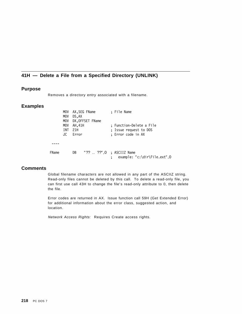
41H — Delete a File from a Specified Directory (UNLINK)
PurposeRemoves a directory entry associated with a filename.
ExamplesMOV AX,SEG FName ; File NameMOV DS,AXMOV DX,OFFSET FNameMOV AH,41H ; Function-Delete a FileINT 21H ; Issue request to DOSJC Error ; Error code in AX
----
FName DB ″?? .. ??″,0 ; ASCIIZ Name; example: ″c:\dir\File.ext″,0
CommentsGlobal filename characters are not allowed in any part of the ASCIIZ string.Read-only files cannot be deleted by this call. To delete a read-only file, youcan first use call 43H to change the file′s read-only attribute to 0, then deletethe file.
Error codes are returned in AX. Issue function call 59H (Get Extended Error)for additional information about the error class, suggested action, andlocation.
Network Access Rights: Requires Create access rights.
218 PC DOS 7

42H — Move File Read/Write Pointer (LSEEK)
PurposeMoves the read/write pointer according to the method specified.
ExamplesMOV AH,42H ; Function Call —
; Move Read/Write PointerMOV AL,Method ; Method of Positioning:
; 0 = From Beginning of File; (BOF); 1 = From Current Position; 2 = From End of File (EOF)
MOV BX,Handle ; Select FileMOV DX,WORD PTR Position+0 ; New Position = Position + METHODMOV CX,WORD PTR Position+2INT 21H ; Issue request to DOSJC Error ; Error code in AXMOV WORD PTR Position+0,AX ; Set new File PositionMOV WORD PTR Position+2,DX
----
Handle DW ? ; File Handle (from Open /; Create)
Position DD ? ; File Offset (may be; negative)
Method DB ?
CommentsOn entry, AL contains a method value. BX contains the file handle. CX:DXcontains the desired offset in bytes with CX containing the most significantpart. On return, DX:AX contains the new location of the pointer with DXcontaining the most significant part if the carry flag is not set.
Error codes are returned in AX. Issue function call 59H (Get Extended Error)for additional information about the error class, suggested action, andlocation.
This function call moves the read/write pointer according to the followingmethods:
Appendix B. PC DOS 7 Function Calls 219

Note: If an LSEEK operation is performed on a file that resides on a networkdisk that is open in either DenyRead or DenyNone sharing mode, theread/write pointer information is adjusted on the computer where thefile actually exists. If the file is opened in any other sharing mode, theread/write pointer information is kept on the remote computer.
AL Description
0 The pointer is moved CX:DX bytes (offset) from the beginning of the file.
1 The pointer is moved to the current location plus offset.
2 The pointer is moved to the end-of-file plus offset. This method can beused to determine file′s size.
220 PC DOS 7
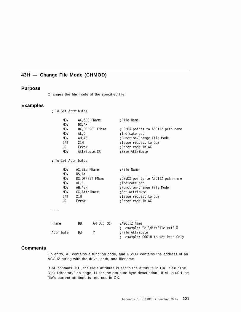
43H — Change File Mode (CHMOD)
PurposeChanges the file mode of the specified file.
Examples; To Get Attributes
MOV AX,SEG FName ;File NameMOV DS,AXMOV DX,OFFSET FName ;DS:DX points to ASCIIZ path nameMOV AL,0 ;Indicate getMOV AH,43H ;Function-Change File ModeINT 21H ;Issue request to DOSJC Error ;Error code in AXMOV Attribute,CX ;Save Attribute
; To Set Attributes
MOV AX,SEG FName ;File NameMOV DS,AXMOV DX,OFFSET FName ;DS:DX points to ASCIIZ path nameMOV AL,1 ;Indicate setMOV AH,43H ;Function-Change File ModeMOV CX,Attribute ;Set AttributeINT 21H ;Issue request to DOSJC Error ;Error code in AX
----
Fname DB 64 Dup (0) ;ASCIIZ Name; example: ″c:\dir\File.ext″,0
Attribute DW ? ;File Attribute; example: 0001H to set Read-Only
CommentsOn entry, AL contains a function code, and DS:DX contains the address of anASCIIZ string with the drive, path, and filename.
If AL contains 01H, the file′s attribute is set to the attribute in CX. See “TheDisk Directory” on page 11 for the attribute byte description. If AL is 00H thefile′s current attribute is returned in CX.
Appendix B. PC DOS 7 Function Calls 221

Error codes are returned in AX. Issue function call 59H (Get Extended Error)for additional information about the error class, suggested action, andlocation.
Note: Only the Archive (20H), Read-Only (01H), System (04H) and Hidden(02H) bits can be changed. All other bits of CX must be 0, otherwise,an error may be indicated.
Network Access Rights: To change the archive bit (AL=20H), no accessrights are required. To change any other bit, Create access rights arerequired.
222 PC DOS 7

44H — I/O Control for Devices
PurposeSets or gets device information associated with open device handles, orsends control strings to the device handle or receives control strings fromthe device handle.
See Appendix C, “I/O Control for Devices (IOCtl)” on page 273 for full detailson this function call.
AL = 00H Get device information (returned in DX).AL = 01H Set device information (determined by DX). DH must be 0 for
this call.AL = 02H Read from character deviceAL = 03H Write to character deviceAL = 04H Read from block deviceAL = 05H Write to block deviceAL = 06H Get input statusAL = 07H Get output statusAL = 08H Determine if a particular block device is removableAL = 09H Determine if a logical device is local or remoteAL = 0AH Determine if a handle is local or remoteAL = 0BH Change sharing retry countAL = 0CH Issue handle generic IOCtl requestAL = 0DH Issue block device generic IOCtl requestAL = 0EH Get logical driveAL = 0FH Set logical driveAL = 10H QueryIOCtlHandleAL = 11H QueryIOCtlDevice
Appendix B. PC DOS 7 Function Calls 223

45H — Duplicate a File Handle (DUP)
PurposeReturns a new file handle for an open file that refers to the same file at thesame position.
ExamplesMOV AH,45H ; Function Call —
; Duplicate a HandleMOV BX,Handle ; Select FileINT 21H ; Issue request to DOSJC Error ; Error code in AXMOV NewHandle,AX ; Save New Handle
----
Handle DW ? ; File Handle (from Open / Create)NewHandle DW ? ; File Handle that duplicates Handle
CommentsOn entry, BX contains the file handle. On return, AX contains the returnedfile handle.
Error codes are returned in AX. Issue function call 59H (Get Extended Error)for additional information about the error class, suggested action, andlocation.
Note: If you move the read/write pointer of either handle by a read, write, orLSEEK function call, the pointer for the other handle is also changed.
224 PC DOS 7

46H — Force a Duplicate of a Handle (FORCDUP)
PurposeForces the handle in CX to refer to the same file at the same position as thehandle in BX.
ExamplesMOV AH,46H ; Function Call —
; Force Duplicate a HandleMOV BX,Handle ; Select fileMOV CX,NewHandle ; Select new definition of FileINT 21H ; Issue request to DOSJC Error ; Error code in AX
----
Handle DW ? ; File Handle (from Open/Create)NewHandle DW ? ; File Handle that duplicates Handle
CommentsOn entry, BX contains the file handle. CX contains a second file handle. Onreturn, the CX file handle refers to the same file at the same position as theBX file handle. If the CX file handle was an open file, it is closed first. If youmove the read/write pointer of either handle, the pointer for the other handleis also changed.
Error codes are returned in AX. Issue function call 59H (Get Extended Error)for additional information about the error class, suggested action, andlocation.
Appendix B. PC DOS 7 Function Calls 225

47H — Get Current Directory
PurposePlaces the full path name (starting from the root directory) of the currentdirectory for the specified drive in the area pointed to by DS:SI.
ExamplesMOV AX,SEG DName ; Directory Name BufferMOV DS,AXMOV SI,OFFSET DName ; OS:SI points to bufferMOV DL,Drive ; Select DriveMOV AH,47H ; Function-Get Current DirINT 21H ; Issue request to DOSJC Error ; Error code in AX
----
Drive DB ? ; Drive (0=current, 1=A:, 2=b:, ...)DName DB 64 DUP(?) ; ASCIIZ Directory Name Returned
; example: ″dir1\dir2″,0
CommentsThe drive letter is not part of the returned string. The string does not beginwith a backslash and is terminated by a byte containing 00H.
Error codes are returned in AX. Issue function call 59H (Get Extended Error)for additional information about the error class, suggested action, andlocation.
226 PC DOS 7

48H — Allocate MemoryAllocates the requested number of paragraphs of memory.
ExamplesMOV AH,48H ; Function Call —
; Allocate MemoryMOV BX,Paragraphs ; Paragraphs DesiredINT 21H ; Issue request to DOSJNC DoneMOV AH,48H ; Function Call —
; Allocate memory; BX set to largest available memory
INT 21H ; Issue request to DOSDone:
MOV BlockSeg,AX ; Save BlockSeg of memoryMOV Paragraphs,BX
----
Paragraphs DW ? ; Size requested in paragraphs; (Bytes allocated is 16 * Paragraphs)
BlockSeg DW ? ; BlockSeg address of allocated memory
CommentsOn entry, BX contains the number of paragraphs requested. On return, AX:0points to the allocated memory block. If the allocation fails, BX returns thesize of the largest block of memory available in paragraphs.
Error codes are returned in AX. Issue function call 59H (Get Extended Error)for additional information about the error class, suggested action, andlocation.
Appendix B. PC DOS 7 Function Calls 227

49H — Free Allocated Memory
PurposeFrees the specified allocated memory.
ExamplesMOV AH,49H ; Function Call — Free MemoryMOV ES,BlockSeg ; Set address to freeINT 21H ; Issue request to DOSJC Error
----
BlockSeg DW ? ; BlockSeg address of allocated memory
CommentsOn entry, ES contains the segment of the block to be returned to the systempool. On return, the block of memory is returned to the system pool.
Error codes are returned in AX. Issue function call 59H (Get Extended Error)for additional information about the error class, suggested action, andlocation.
228 PC DOS 7

4AH — Modify Allocated Memory Blocks (SETBLOCK)
PurposeModifies allocated memory blocks to contain the new specified block size.
ExamplesMOV AH,4AH ; Function Call —
; Modify Allocated Memory; allocate memoryMOV ES,BlockSeg ; Set address to freeMOV BX,BlockSize ; New size (may be larger or smaller)INT 21H ; Issue request to DOSJNC DoneMOV AH,4AH ; Function Call —
; Allocate memory; BX set to largest available Size
INT 21H ; Issue request to DOSDone:
MOV Size,BX
----
BlockSeg DW ? ; Segment address of allocated memoryBlockSize DW ? ; Size requested in paragraphs
; (Bytes allocated is 16 * Size)
CommentsError codes are returned in AX. Issue function call 59H (Get Extended Error)for additional information about the error class, suggested action, andlocation.
Note: This call is often used to set the size of a program before usingfunction call 31H (Terminate Process and Remain Resident). Use theprogram segment prefix. This value can be obtained using functioncall 62H (Get Program Segment Prefix Address). Another use is torelease memory to prepare for using function call 4BH (Load orExecute a Program).
Appendix B. PC DOS 7 Function Calls 229

4BH — Load or Execute a Program (EXEC)
PurposeAllows a program to load another program into memory and may choose tobegin execution of it.
Examples; To Execute a Program
MOV AH,4BH ; Function Call — Execute a ProgramMOV AL,0 ; Indicate execute programMOV CX,SEG Parms ; Program parametersMOV ES,CXMOV BX,OFFSET Parms : ES:BX points to parameter blockMOV CX,SEG PName ; Program nameMOV DS,CXMOV DX,OFFSET PName ; DS:DX points to program nameMOV WORD PTR StackSave+0,SP ; Save stack pointerMOV WORD PTR StackSave+2,SSINT 21H ; Issue request to DOS
JC Error ; Error code in AX; Note: All Registers (except CS:IP) Destroyed
; Program Runs here
CLI ; Protect from stack usageMOV SS,WORD PTR StackSave+2 ; Restore stack pointerMOV SP,WORD PTR StackSave+0STI ; Enable interruptsMOV AH,4DH ; Function Call — Get Return CodeINT 21H ; Issue request to DOSMOV RetCode,AX ; Save return code
; To Load an OverlayMOV AH,4BH ; Function Call — Execute a ProgramMOV AL,3 ; Indicate load overlayMOV CX,SEG OParms ; Overlay parametersMOV ES,CXMOV BX,OFFSET OParms ; ES:BX points to parameter blockMOV CX,SEG PName ; Overlay nameMOV DS,CXMOV DX,OFFSET PName ; DS:DX points to overlay filenameINT 21H ; Issue request to DOS
JC Error ; Error code in AX
230 PC DOS 7

----PName DB 64 Dup (0) ; ASCIIZ Name
; example: ″c:\dir\File.ext″,0Parms LABEL WORD ; Program parametersEnv@ DW ? ; Environment segment address
; Value of 0000H indicates copy EXEC′ ers; Environment
Cmd@ DD ? ; Command line addressFCB1@ DD ? ; FCB Image to set to New PSP+5CHFCB2@ DD ? ; FCB Image to set to New PSP+6CH
StackSave DD ? ; Stack pointer save areaRetCode DW ? ; Program return code
; (see function code 4DH for more information)OParms LABEL WORD ; Overlay parametersLoad@ DW ? ; Overlay load segment address
RelocFactor DW ? ; Relocation factor to apply (for .EXE files)
CommentsError codes are returned in AX. Issue function call 59H (Get Extended Error)for additional information about the error class, suggested action, andlocation. Refer to “Responding to Errors” on page 138 and “Extended ErrorCodes” on page 138 for more information on the codes returned fromfunction call 59H.
The following function values are allowed in AL:
Only the first 20 file handles are duplicated in the newly created processafter an EXEC, unless the file was opened with the inheritance bit set to 1.This means that the parent process has control over the meanings ofstandard input, output, auxiliary, and printer devices. The parent could, forexample, write a series of records to a file, open the file as standard input,open a listing file as standard output, and then execute a sort program thattakes its input from standard input and writes to standard output.
FunctionValue Description
00H Load and execute the program. A program segment prefix isestablished for the program; terminate and Ctrl-Break addresses are setto the instruction after the EXEC system call.
Note: When control is returned, all registers are changed, including thestack. You must restore SS, SP, and any other required registersbefore proceeding.
03H Load, do not create the program segment prefix, and do not beginexecution. This is useful in loading program overlays.
Appendix B. PC DOS 7 Function Calls 231

Also inherited (or copied from the parent) is an “environment.” This is ablock of text strings (less than 32KB total) that conveys various configurationparameters. The following is the format of the environment (always on aparagraph boundary):
Typically the environment strings have the form:
parameter = value
Following the byte of 0 in the environment is a WORD that indicates thenumber of other strings following. Following this is a copy of the DS:DXfilename passed to the child process. For example, the string VERIFY=ONcould be passed. A 0 value of the environment address causes the newlycreated process to inherit the original environment unchanged. The segmentaddress of the environment is placed at offset 2CH of the program segmentprefix for the program being invoked.
Errors codes are returned in AX. Refer to “Responding to Errors” onpage 138 and “Extended Error Codes” on page 138 for more information onthe codes returned.
Note: When your program received control, all available memory wasallocated to it. You must free some memory (see call 4AH) beforeEXEC can load the program you are invoking. Normally, you wouldshrink down to the minimum amount of memory you need, and freethe rest.
Byte ASCIIZ string 1
Byte ASCIIZ string 2
...
Byte ASCIIZ string n
Byte of 0
232 PC DOS 7

4CH — Terminate a Process (EXIT)
PurposeTerminates the current process and transfers control to the invoking process.
ExamplesMOV AH,4CH ; Function Call — Terminate a ProcessMOV AL,ErrorCode ; Set ERRORLEVELINT 21H ; Issue request to DOSINT 20H ; Be safe if running on PC/DOS 1.1
----
ErrorCode DB ? ; Error Code (sets ERRORLEVEL if EXEC′ ed; by COMMAND.COM)
CommentsIn addition, a return code can be sent. The return code can be interrogatedby the batch subcommands IF and ERRORLEVEL and by the wait function call4DH. All files opened by this process are closed.
Appendix B. PC DOS 7 Function Calls 233
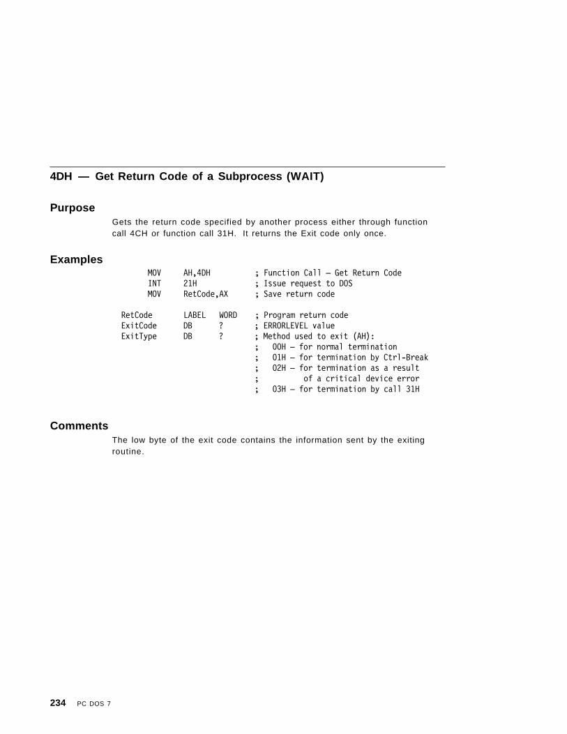
4DH — Get Return Code of a Subprocess (WAIT)
PurposeGets the return code specified by another process either through functioncall 4CH or function call 31H. It returns the Exit code only once.
ExamplesMOV AH,4DH ; Function Call — Get Return CodeINT 21H ; Issue request to DOSMOV RetCode,AX ; Save return code
RetCode LABEL WORD ; Program return codeExitCode DB ? ; ERRORLEVEL valueExitType DB ? ; Method used to exit (AH):
; 00H — for normal termination; 01H — for termination by Ctrl-Break; 02H — for termination as a result; of a critical device error; 03H — for termination by call 31H
CommentsThe low byte of the exit code contains the information sent by the exitingroutine.
234 PC DOS 7

4EH — Find First Matching File (FIND FIRST)
PurposeFinds the first filename that matches the specified file specification.
ExamplesMOV AH,1AH ; Function Call — Set DTA AddressMOV CX,SEG DTA ; Address buffer for found fileMOV DS,CXMOV DX,OFFSET DTAINT 21H ; Issue request to DOSMOV AH,4EH ; Function Call — ASCIIZ Find FirstMOV CX,SEG FName ; Directory or filenameMOV DS,CXMOV DX,OFFSET FName ; DS:DX points to ASCII filenameMOV CX,Attribute ; Set Match AttributeINT 21H ; Issue request to DOSJC Error ; Error code in AX
----
DTA LABEL BYTE ; Find return informationDB 21 DUP(0) ; Reserved for PC DOS 7 to continue find
FileAttr DB ? ; Matched files attribute low byteFileTime DW ? ; File timeFileDate DW ? ; File dateFileSize DD ? ; File sizeFileNameExt DB ″????????.???″,0 ; Filename and extension
FName DB 64 DUP (0) ; ASCIIZ Name; example: ″c:\dir\*.*″,0
Attribute DW ? ; Select files attribute; Combination of following:; 0001H=Read only; 0002H=Hidden; 0004H=System; 0008H=Volume label; 0010H=Directory; 0040H=Reserved; 0080H=Reserved
Appendix B. PC DOS 7 Function Calls 235

Notes:
1. If the attribute is 0, only normal file entries are found. Entries for volumelabel, subdirectories, hidden files, and system files are not returned.
2. If the attribute field is set for hidden files, or system files, or directoryentries, it is to be considered as an inclusive search. All normal fileentries plus all entries matching the specified attributes are returned. Tolook at all directory entries except the volume label, the attribute bytemay be set to hidden + system + directory (all 3 bits on).
CommentsThe filename in DS:DX can contain global filename characters. The ASCIIZstring cannot contain a network path. See function call 11H (Search for FirstEntry) for a description of how the attribute bits are used for searches.
Error codes are returned in AX. Issue function call 59H (Get Extended Error)for additional information about the error class, suggested action, andlocation. Refer to “Responding to Errors” on page 138 and “Extended ErrorCodes” on page 138 for more information on the codes returned fromfunction call 59H.
Note: The name and extension of file found is returned as an ASCIIZ string.All blanks are removed from the name and extension, and, if anextension is present, it is preceded by a period.
236 PC DOS 7

4FH — Find Next Matching File (FIND NEXT)
PurposeFinds the next directory entry matching the name that was specified on theprevious Find First or Find Next function call.
ExamplesMOV AH,1AH ; Function Call — Set DTA AddressMOV CX,SEG DTA ; Address buffer for found fileMOV DS,CXMOV DX,OFFSET DTAINT 21H ; Issue request to DOSMOV AH,4FH ; Function Call — Find nextINT 21H ; Issue request to DOSJC Error ; Error code in AX
----
DTA LABEL BYTE ″ ; Find Return InformationDB 21 DUP(0) ″ ; Reserved for DOS to Continue Find
″ ; Set by Find First or Previous Find NextFileAttr DB ? ″ ; Matched Files Attribute Low ByteFileTime DW ? ″ ; File TimeFileDate DW ? ″ ; File DateFileSize DD ? ″ ; File SizeFileNameExt DB ″????????.???″,0 ; File Name and Extension
CommentsIf a matching file is found, the DTA is set as described in call 4EH (Find FirstMatching File (FIND FIRST)). If no more matching files are found, an errorcode is returned.
Error codes are returned in AX. Issue function call 59H (Get Extended Error)for additional information about the error class, suggested action, andlocation.
Appendix B. PC DOS 7 Function Calls 237

50H — Set Program Segment Prefix Address
PurposeSets the segment address of the current programs, program segment prefix.
ExamplesMOV BX,SEGMENT_PSP ; Segment Address of New PSPMOV AH,50H ; Function Call — Set PSP AddressINT 21H ; Issue request to DOS
; No Return----SEGMENT_PSP DW ? ; Segment Address of PSP
238 PC DOS 7

51H — Get Program Segment Prefix Address
PurposeReturns the segment address of the currently executing programs, programsegment prefix.
ExamplesMOV AH,51H ; Function Call — Get PSP AddressINT 21H ; Issue request to DOSJC Error ; Error Code in AX
MOV SEGMENT_PSP,BX ; Save PSP Address----SEGMENT_PSP DW ? ; Segment Address of PSP
CommentsThis function is identical to Interrupt 21H function 62H.
Appendix B. PC DOS 7 Function Calls 239

54H — Get Verify Setting
PurposeReturns the value of the verify flag.
Examples
MOV AH,54H ; Function Call — Get VERIFY SettingINT 21H ; Issue request to DOSMOV VERIFY,AL ; Save VERIFY State
-----
VERIFY DB ? ; VERIFY State:; 0 = OFF; 1 = ON
CommentsOn return, AL returns 00H if verify is OFF, 01H if verify is ON. Note that theverify switch can be set through call 2EH (Set/Reset Verify Switch).
240 PC DOS 7

56H — Rename a File
PurposeRenames the specified file.
Examples
MOV AH,56H ; Function Call — ASCIIZ Rename FileMOV CX,SEG FName ; File NameMOV DS,CXMOV DX,OFFSET FName ; DS:DX points to original nameMOV CX,SEG NewName ; New File NameMOV ES,CXMOV DI,OFFSET NewName ; ES:DI points to renameINT 21H ; Issue request to DOSJC Error ; Error code in AX
----
FName DB 64 DUP (0) ; ASCIIZ Name; example: ″c:\dir\abc.lst″,0
NewName DB 64 DUP (0) ; ASCIIZ Name; example: ″\dir\xyz.lst″,0
CommentsIf a drive is used in the NewName string, it must be the same as the drivespecified or implied in the Name string. The directory paths need not be thesame, allowing a file to be moved to another directory and renamed in theprocess. Directory names can be changed but not moved. Global filenamecharacters are not allowed in the filename.
Error codes are returned in AX. Issue function call 59H (Get Extended Error)for additional information about the error class, suggested action, andlocation. Refer to “Responding to Errors” on page 138 and “Extended ErrorCodes” on page 138 for more information on the codes returned fromfunction call 59H.
Network Access Rights: Requires Create access rights.
Appendix B. PC DOS 7 Function Calls 241

57H — Get/Set File ′s Date and Time
PurposeGets or sets a file′s date and time.
Examples; To Get a File′ s Date and Time
MOV AH,57H ; Function Call — Get/Set Date and TimeMOV AL,0 ; Indicate getMOV BX,Handle ; Select fileINT 21H ; Issue request to DOSJC Error ; Error code in AXMOV FileTime,CX ; Save TimeMOV FileDate,DX ; Save Date
; To Set a File′ s Date and Time
MOV AH,57H ; Function Call — Get/Set Date and TimeMOV AL,1 ; Indicate SetMOV BX,Handle ; Select file+MOV CX,FileTime ; Set TimeMOV DX,FileDate ; Set DateINT 21H ; Issue request to DOSJC Error ; Error code in AX
----
Handle DW ? ; File Handle (from Open / Create)FileTime DW ? ; File TimeFileDate DW ? ; File Date
CommentsThe date and time formats are the same as those for the directory entrydescribed in Chapter 5 of this book.
Error codes are returned in AX. Issue function call 59H (Get Extended Error)for additional information about the error class, suggested action, andlocation. Refer to “Responding to Errors” on page 138 and “Extended ErrorCodes” on page 138 for more information on the codes returned fromfunction call 59H.
242 PC DOS 7

5800H — Get Allocation Strategy
PurposeReturns the scheme in which PC DOS 7 uses to allocate memory.
ExamplesMOV AH,5800H ; Function Call — Get Allocation StrategyINT 21H ; Issue request to DOS
JC ErrorMOV STRATEGY,AX ; Save Allocation Strategy
----STRATEGY DW ? ; Allocation Strategy
CommentsThe following table describes the allocation strategies returned values:
Table 1 (Page 1 of 2). Allocation Strategies
Value Description
FIRST_FIT_LOW 0000H Search conventional memory for anavailable block having the lowestaddress. This is also the defaultstrategy.
BEST_FIT_LOW 0001H Search conventional memory for anavailable block that closely matchesthe requested size.
LAST_FIT_LOW 0002H Search conventional memory for anavailable block at the highest address.
FIRST_FIT_HIGH 0080H Search the upper-memory area for anavailable block at the lowest address.If no block is found then the searchcontinues in the conventional memory.
BEST_FIT_HIGH 0081H Search the upper-memory area for anavailable block that closely matchesthe requested size. If no block is foundthen the search continues in theconventional memory.
LAST_FIT_HIGH 0082H Search the upper-memory area for anavailable block at the highest address.If no block is found then the searchcontinues in the conventional memory.
Appendix B. PC DOS 7 Function Calls 243

Table 1 (Page 2 of 2). Allocation Strategies
Value Description
FIRST_FIT_HIGHONLY 0040H Search the upper-memory area for anavailable block at the lowest address.
BEST_FIT_HIGHONLY 0041H Search the upper-memory area for anavailable block that closely matchesthe requested size.
LAST_FIT_HIGHONLY 0042H Search the upper-memory area for anavailable block at the highest address.
244 PC DOS 7

5801H — Set Allocation Strategy
PurposeSets the scheme by which PC DOS 7 uses to allocate memory.
ExamplesMOV BX,STRATEGY ; Allocation StrategyMOV AH,5801H ; Function Call — Set Allocation StrategyINT 21H ; Issue request to DOS
JC Error----STRATEGY DW ? ; Allocation Strategy
CommentsThe strategy used is the same as described in the table on Table 1 onpage 243.
After the function is called the carry flag will be clear if it has beensuccessfull. If the carry flag is set the AX register contains an error, whichcould be 0001H, indicating that the strategy is not one of the ones specified.
Appendix B. PC DOS 7 Function Calls 245
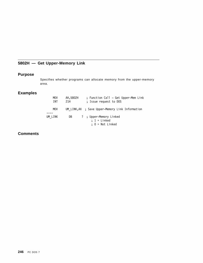
5802H — Get Upper-Memory Link
PurposeSpecifies whether programs can allocate memory from the upper-memoryarea.
ExamplesMOV AH,5802H ; Function Call — Get Upper-Mem LinkINT 21H ; Issue request to DOS
MOV UM_LINK,AX ; Save Upper-Memory Link Information----UM_LINK DB ? ; Upper-Memory Linked
; 1 = Linked; 0 = Not Linked
Comments
246 PC DOS 7

5803H — Set Upper-Memory Link
PurposeAllows you to link or unlink the upper-memory area. If linked, a programmay allocate memory from the upper-memory area.
ExamplesMOV BX,UM_LINK ; Set Upper-Memory Link InformationMOV AH,5802H ; Function Call — Set Upper-Mem LinkINT 21H ; Issue request to DOSJC Error ; AX contains the error value
; 0001H ERROR_INVALID_FUNCTION; 0007H ERROR_ARENA_TRASHED
----UM_LINK DB ? ; Upper-Memory Linked
; 1 = Link Upper-Memory Area; 0 = Unlink Upper-Memory Area
CommentsThe return of the 0001H error (ERROR_INVALID_FUNCTION) could indicatethat PC DOS 7 has been loaded without DOS=UMB being specified in theCONFIG.SYS file.
Appendix B. PC DOS 7 Function Calls 247

59H — Get Extended Error
PurposeReturns additional error information, such as the error class, location, andrecommended action.
Examples
PUSH DX ; Save RegistersPUSH SIPUSH DIPUSH ESPUSH DSMOV AH,59H ; Function Call — Get Extended ErrorMOV BX,0 ; Version 0 informationINT 21H ; Issue request to DOSPOP DS ; Restore registersPOP ESPOP DIPOP SIPOP DXMOV ExtError,AX ; Save error codeMOV ErrorClass,BH ; Save error classMOV ErrorAction,BL ; Save error actionMOV ErrorLocation,CH; Save error location
----
ExtError DW ? ; DOS extended errorErrorClass DB ? ; Class of errorErrorAction DB ? ; Suggested actionErrorLocation DB ? ; System area effected
CommentsThis function call returns the error class, location, and recommended action,in addition to the return code. Use this function call from:
• Interrupt 24H error handlers• Interrupt 21H function calls that return an error in the carry bit• FCB function calls that return FFH.
248 PC DOS 7

On return, the registers contents of DX, SI, DI, ES, CL, and DS are destroyed.
Error Return in Carry Bit
For function calls that indicate an error by setting the carry flag, the correctmethod for performing function call 59H is:
• Load registers.• Issue interrupt 21H.• Continue operation, if carry not set.• Disregard the error code and issue function call 59H to obtain additional
information.• Use the value in BL to determine the suggested action to take.
Error Status in AL
For function calls that indicate an error by setting AL to FFH, the correctmethod for performing function call 59H is:
• Load registers.• Issue interrupt 21H.• Continue operation, if error is not reported in AL.• Disregard the error code and issue function call 59H to obtain additional
information.• Use the value in BL to determine the suggested action to take.
Appendix B. PC DOS 7 Function Calls 249

5AH — Create Unique File
PurposeGenerates a unique filename, and creates that file in the specified directory.
Examples
MOV AH,5AH ; Function Call — Create a; Unique File
MOV CX,SEG DirName ; Directory nameMOV DS,CXMOV DX,OFFSET DirNameMOV CX,Attribute ; File attributeINT 21H ; Issue request to DOSJC Error ; Error code in AXMOV Handle,AX ; Save file handle for following
; Operations
----
DirName DB ″?? .. ??\″,0 ; ASCIIZ nameDB ″????????.???″
; example in : ″c:\dir\″,0; example out: ″c:\dir\file″,0
Handle DW ? ; File handleAttribute DW ? ; Select file′ s attribute
CommentsOn entry, AH contains 5AH. If no error has occurred, the file is opened incompatibility mode with Read/Write access. The read/write pointer is set atthe first byte of the file and AX contains the file handle and the filename isappended to the path specified in DS:DX.
This function call generates a unique name and attempts to create a new filein the specified directory. If the file already exists in the directory, thenanother unique name is generated and the process is repeated. Programsthat need temporary files should use this function call to generate uniquefilenames.
Error codes are returned in AX. Issue function call 59H (Get Extended Error)for additional information about the error class, suggested action, andlocation. Refer to “Responding to Errors” on page 138 and “Extended Error
250 PC DOS 7

Codes” on page 138 for more information on the codes returned fromfunction call 59H.
Note: The file created using this function call is not automatically deleted atprogram termination.
Network Access Rights: Requires Create access rights.
Appendix B. PC DOS 7 Function Calls 251

5BH — Create New File
PurposeCreates a new file.
Examples
MOV AH,5BH ; Function Call — Create a New FileMOV CX,SEG FName ; File NameMOV DS,CXMOV DX,OFFSET FNameMOV CX,AttributeINT 21H ; Issue request to DOSJC Error ; Error code in AXMOV Handle,AX ; Save File Handle for following operations
----
FName DB 64 DUP (0) ; ASCIIZ Name; example: ″c:\dir\file″,0
Handle DW ? ; File HandleAttribute DW ? ; Select File′ s Attribute
CommentsThis function call is the same as function call 3CH (Create), except it will failif the filename already exists. The file is created in compatibility mode forreading and writing and the read/write pointer is set at the first byte of thefile.
Error codes are returned in AX. Issue function call 59H (Get Extended Error)for additional information about the error class, suggested action, andlocation. Refer to “Responding to Errors” on page 138 and “Extended ErrorCodes” on page 138 for more information on the codes returned fromfunction call 59H.
Network Access Rights: Requires Create access rights.
252 PC DOS 7

5CH — Lock/Unlock File Access
PurposeLocks or unlocks a single range of bytes in an opened file. This function callprovides database services that are useful in maintaining database integrityin a network environment.
Examples; To Lock a Single Range
MOV AH,5CH ; Function Call —; Access Lock/Unlock File
MOV AL,0 ; Indicate lockMOV BX,Handle ; Select fileMOV DX,WORD PTR Position+0 ; Set positionMOV CX,WORD PTR Position+2MOV DI,WORD PTR Llength+0 ; Set lengthMOV SI,WORD PTR Llength+2INT 21H ; Issue request to DOSJC Error ; Error code in AX
; To Unlock a Single Range
MOV AH,5CH ; Function Call —; Lock/Unlock File Access
MOV AL,1 ; Indicate unlockMOV BX,Handle ; Select fileMOV DX,WORD PTR Position+0 ; Set positionMOV CX,WORD PTR Position+2MOV DI,WORD PTR Llength+0 ; Set lengthMOV SI,WORD PTR Llength+2INT 21H ; Issue request to DOSJC Error ; Error code in AX
----
Handle DW ? ; File HandlePosition DD ? ; Start of RangeLlength DD ? ; Length of Range
Appendix B. PC DOS 7 Function Calls 253

CommentsThe Lock/Unlock function calls should only be used when a file is openedusing the DenyRead or DenyNone sharing modes. These modes do no localbuffering of data when accessing files on a network disk.
AL = 00H LockLock provides a simple mechanism for excluding other processes′ read/writeaccess to regions of the file. If another process attempts to read or write insuch a region, its system call is retried the number of times specified withthe system retry count set by IOCTL. If, after those retries, no successoccurs, a general failure error is generated, signaling the condition. Thenumber of retries, as well as the length of time between retries, can bechanged using function call 440BH (IOCTL Change Sharing Retry Count).
The recommended action is to issue function call 59H (Get Extended Error) toget the error code, in addition to the error class, location, and recommendedaction. The locked regions can be anywhere in the logical file. Lockingbeyond end-of-file is not an error. It is expected that the time in whichregions are locked will be short. Duplicating the handle duplicates access tothe locked regions. Access to the locked regions is not duplicated across theEXEC system call. Exiting with a file open and having issued locks on thatfile has undefined results.
Programs that may be cancelled using INT 23H or INT 24H should trap theseinterrupts and release the locks before exiting from the program. The propermethod for using locks is not to rely on being denied read or write access,but to attempt to lock the region desired and examining the error code.
AL = 01H UnlockUnlock releases the lock issued in the lock system call. The region specifiedmust be exactly the same as the region specified in the previous lock.Closing a file with locks still in force has undefined results. Exiting with a fileopen and having issued locks on that file has undefined results.
Programs that may be abended using INT 23H or INT 24H should trap theseinterrupts and release the lock before exiting from the program. The propermethod for using locks is not to rely on being denied read or write accessbut rather attempting to lock the region desired and examining the errorcode.
Error codes are returned in AX. Issue function call 59H (Get Extended Error)for additional information about the error class, suggested action, andlocation. Refer to “Responding to Errors” on page 138 and “Extended ErrorCodes” on page 138 for more information on the codes returned fromfunction call 59H.
254 PC DOS 7

5D0AH — Set Extended Error
PurposeThis function sets the error class, location suggested action and otherinformation that will be returned by the next call to function 59H GetExtended Error.
ExamplesMOV DX, SEG ERROR_INFOMOV DS,DXMOV DX, OFFSET ERROR_INFO
MOV AH,5D0AH ; Function Call — Set Extended ErrorINT 21H ; Issue request to DOS
----ERROR_INFO STRUC
ExtendedErr DW ? ; Extended Error CodeErrorClass DB ? ; Error ClassErrorAction DB ? ; Suggested ActionErrorLoc DB ? ; Location of ErrorerrCL DB ? ; CL RegistererrDX DW ? ; DX RegistererrSI DW ? ; SI RegistererrDI DW ? ; DI RegistererrDS DW ? ; DS RegistererrES DW ? ; ES RegistererrReserved DW ? ; Reserved WorderrUID DW ? ; USER IDerrPID DW ? ; Program ID
CommentsPlease refer to “Responding to Errors” on page 138 for details of thepossible values that may be used in the ERROR_INFO structure.
Appendix B. PC DOS 7 Function Calls 255
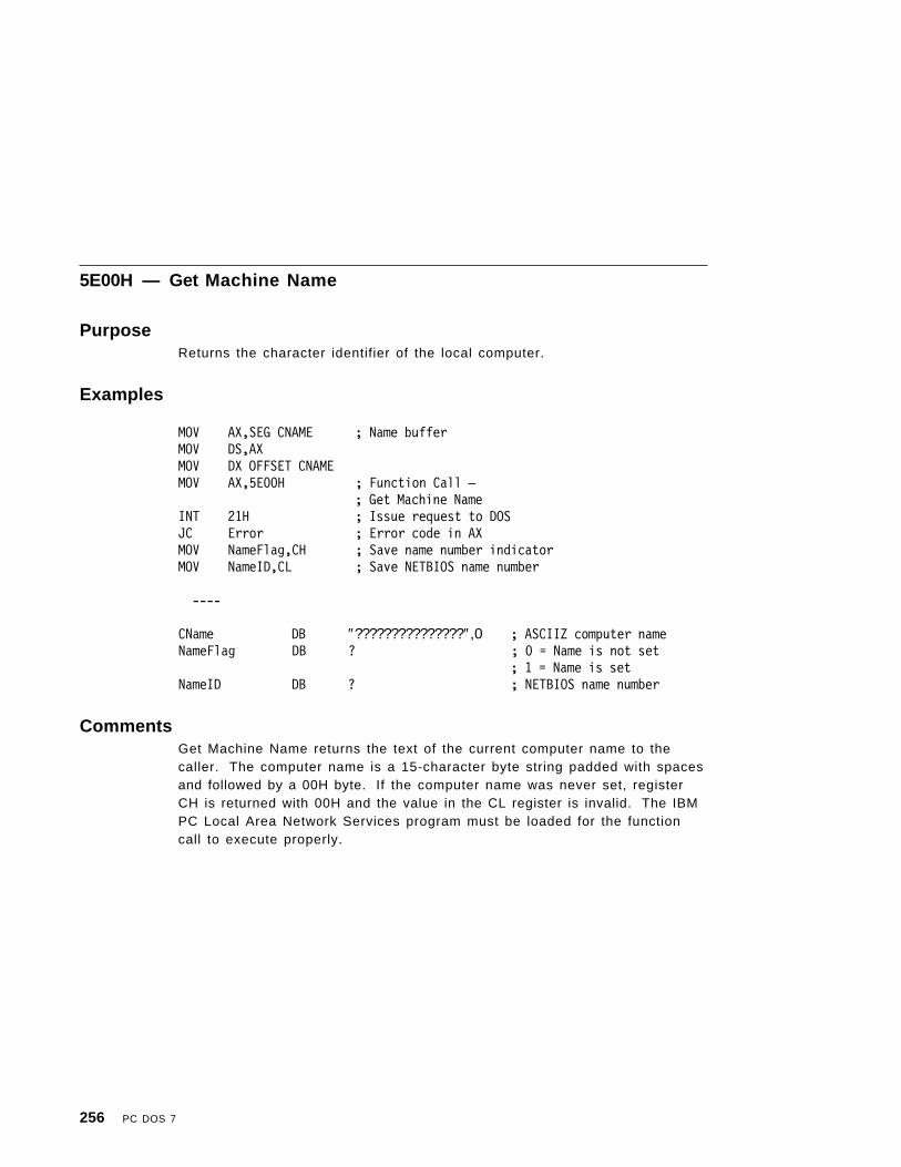
5E00H — Get Machine Name
PurposeReturns the character identifier of the local computer.
Examples
MOV AX,SEG CNAME ; Name bufferMOV DS,AXMOV DX OFFSET CNAMEMOV AX,5E00H ; Function Call —
; Get Machine NameINT 21H ; Issue request to DOSJC Error ; Error code in AXMOV NameFlag,CH ; Save name number indicatorMOV NameID,CL ; Save NETBIOS name number
----
CName DB ″???????????????″,0 ; ASCIIZ computer nameNameFlag DB ? ; 0 = Name is not set
; 1 = Name is setNameID DB ? ; NETBIOS name number
CommentsGet Machine Name returns the text of the current computer name to thecaller. The computer name is a 15-character byte string padded with spacesand followed by a 00H byte. If the computer name was never set, registerCH is returned with 00H and the value in the CL register is invalid. The IBMPC Local Area Network Services program must be loaded for the functioncall to execute properly.
256 PC DOS 7

5E02H — Set Printer Setup
PurposeSpecifies an initial string for printer files.
ExamplesMOV AX,5E02H ; Function Call —
; Set Printer SetupMOV BX,Index ; Redirection List IndexMOV CX,size ; String sizeMOV SI,SEG String ; String BufferMOV DS,SIMOV SI,OFFSET StringINT 21H ; Issue request to DOSJC Error ; Error code in AX
----
Index DW ? ; Redirection List IndexSize DW N ; String size (Maximum 64)String DB N DUP(?) ; Printer Setup String
CommentsThe string specified is put in front of all files destined for a particular networkprinter. Set Printer Setup allows multiple users of a single printer to specifytheir own mode of operation for the printer. BX is set to the same index thatis used in function call 5F02H (Get Redirection List Entry). An error code isreturned if print redirection is paused or if the IBM PC Local Area NetworkServices program is not loaded.
Error codes are returned in AX. Issue function call 59H (Get Extended Error)for additional information about the error class, suggested action, andlocation. Refer to “Responding to Errors” on page 138 and “Extended ErrorCodes” on page 138 for more information on the codes returned fromfunction call 59H. IMPORTANT: The redirection index value may change iffunction call 5F03H (Redirect Device) or function call 5F04H (CancelRedirection) is issued between the time the redirection list is scanned andthe function call 5E02H (Set Printer Setup) is issued. Therefore, werecommend that you issue Set Printer Setup immediately after you issue“Get Redirection List .”
Appendix B. PC DOS 7 Function Calls 257
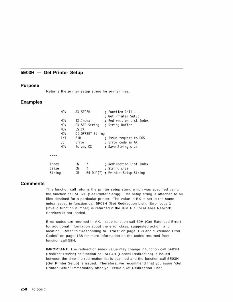
5E03H — Get Printer Setup
PurposeReturns the printer setup string for printer files.
Examples
MOV AX,5E03H ; Function Call —; Get Printer Setup
MOV BX,Index ; Redirection List IndexMOV CX,SEG String ; String BufferMOV ES,CXMOV DI,OFFSET StringINT 21H ; Issue request to DOSJC Error ; Error code in AXMOV Ssize, CX ; Save String size
----
Index DW ? ; Redirection List IndexSsize DW ? ; String sizeString DB 64 DUP(?) ; Printer Setup String
CommentsThis function call returns the printer setup string which was specified usingthe function call 5E02H (Set Printer Setup). The setup string is attached to allfiles destined for a particular printer. The value in BX is set to the sameindex issued in function call 5F02H (Get Redirection List). Error code 1(invalid function number) is returned if the IBM PC Local Area NetworkServices is not loaded.
Error codes are returned in AX. Issue function call 59H (Get Extended Error)for additional information about the error class, suggested action, andlocation. Refer to “Responding to Errors” on page 138 and “Extended ErrorCodes” on page 138 for more information on the codes returned fromfunction call 59H.
IMPORTANT: The redirection index value may change if function call 5F03H(Redirect Device) or function call 5F04H (Cancel Redirection) is issuedbetween the time the redirection list is scanned and the function call 5E03H(Get Printer Setup) is issued. Therefore, we recommend that you issue “GetPrinter Setup” immediately after you issue “Get Redirection List.”
258 PC DOS 7

5F02H — Get Redirection List Entry
PurposeReturns nonlocal network assignments.
Examples
MOV BX,0 ; Start at beginning of listGet_Loop: ; Get next entry
MOV Index,BX ; Redirection list indexMOV AX,5F02H ; Function Call —
; Get redirection list entryMOV SI,SEG device ; ″PRN″ is possibleMOV DS,SIMOV SI,OFFSET device ; DS:SI points to local nameMOV DI,SEG infoMOV ES,DIMOV DI,OFFSET inf ; ES:DI points to buffer address of network namePUSH BXPUSH DX ; Save registersPUSH BPINT 21H ; Issue request to DOSPOP BP ; Restore registersPOP DX
JC CheckEnd ; Error code in AXMOV Status,BH ; Save statusMOV Type,BL ; Save typeMOV UserParm,CX ; Save user parameterPOP BXINC BX ; Set to next entryJMP Get_Loop
CheckEnd:POP BX ; Balance stateCMP AX,18 ; End of list?JNE Error ; No!
----
Index DW ? ; Redirection list index (0 based)Device DB 128 DUP(?) ; ASCIIZ device name
; example: ″LPT1″,0; ″A:″,0
Status DB ? ; Device status; Bit 0=0 : Device is OK
Appendix B. PC DOS 7 Function Calls 259

; Bit 0=1 : Device in Error; Bit 7-1 reserved
UserParm DW ? ; User parameterType DB ? ; Device type
; 3 = NET USE device; 4 = NET USE drive
Info DB 128 DUP(?) ; NET USE network path; example: ″\\MYNODE\CDRIVE″,0
CommentsThe Get Redirection List Entry function call returns the list of networkredirections that were created through function call 5F03H (Redirect Device).Each call returns one redirection, so BX should be increased by one eachtime to step through the list. The contents of the list may change betweencalls. The end-of-list is detected by error code 18 (no more files). Error code1 (invalid function number) is returned if the IBM PC Local Area NetworkServices program and IFSFUNC are not loaded.
If either disk or print redirection is paused, the function is not effected.
Error codes are returned in AX. Issue function call 59H (Get Extended Error)for additional information about the error class, suggested action, andlocation. Refer to “Responding to Errors” on page 138 and “Extended ErrorCodes” on page 138 for more information on the codes returned fromfunction call 59H.
260 PC DOS 7

5F03H — Redirect Device
PurposeCauses a Redirector/Server connection to be made.
ExamplesMOV AX,5F03H ; Function Call —
; Redirect DeviceMOV SI,SEG Device ; Device BufferMOV DS,SIMOV SI,OFFSET DeviceMOV DI,SEG Net Path info ; Information BufferMOV ES,DIMOV DI,OFFSET Net PathMOV BL,Type ; Set TypeMOV CX,UserParm ; Set User ParameterINT 21H ; Issue request to DOSJC Error ; Error code in AX
----
Device DB ″ . . . . ″ , 0 ; ASCIIZ Device Name; example: ″LPT1″,0; ″A:″,0
UserParm DW ? ; User ParameterType DB ? ; Device Type
; 3 = NET USE Device; 4 = NET USE Drive
Net Path DB 128 DUP(0)
CommentsThis call defines the current directories for the network and definesredirection of network printers.
• If BL = 03, the source specifies a printer, the destination specifies anetwork path, and the CX register has a word that PC DOS 7 maintainsfor the programmer. For compatibility with the IBM PC Local AreaNetwork Services program, CX should be set to 0. Values other than 0are reserved for the IBM PC Local Area Network Services program. Thisword may be retrieved through function call 5F02H (Get Redirection List).All output destined for the specified printer is buffered and sent to theremote printer spool for that device. The printers are redirected at theINT 17H level.
Appendix B. PC DOS 7 Function Calls 261

The source string must be PRN , LPT1 , LPT2, or LPT3 each ended with a00H. The destination string must point to a network name string of thefollowing form:
[computername{shortname∨printdevice}]
The destination string must be ended with a 00H.
The ASCIIZ password (0 to 8 characters) for access to the remote deviceshould immediately follow the network string. The password must endwith a 00H. A null (0 length) password is considered to be no password.
• If BL = 4, the source specifies a drive letter and colon ending with 00H,the destination specifies a network path ending with 00H, and the CXregister has a word that DOS maintains for the programmer. Forcompatibility with the IBM PC Local Area Network Services program, CXshould be set to 00H. Values other than 00H are reserved for the IBM PCLocal Area Network Services program. The value may be retrievedthrough function call 5F02H (Get Redirection List). If the source was adrive letter, the association is made between the drive letter and thenetwork path. All subsequent references to the drive letter are translatedto references to the network path. If the source is an empty string, thesystem attempts to grant access to the destination with the specifiedpassword without redirecting any device.
The ASCIIZ password for access to the remote path should immediatelyfollow the network string. A null (0 length) password ended with 00H isconsidered to be no password.
Error codes are returned in AX. Issue function call 59H for additionalinformation about the error class, suggested action, and location. Referto “Responding to Errors” on page 138 and “Extended Error Codes” onpage 138 for more information on the codes returned from function call59H (Get Extended Error) .
Notes:
1. Devices redirected through this function call are not displayed by the NETUSE command.
2. An error is returned if you try to redirect a drive while disk redirection ispaused, or if you try to redirect a printer while print redirection ispaused.
262 PC DOS 7

5F04H — Cancel Redirection
PurposeCancels a previous redirection.
Examples
MOV AX,5F04H ; Function Call —; Cancel redirection
MOV SI,SEG Device ; Device bufferMOV DS,SIMOV SI,OFFSET DeviceINT 21H ; Issue request to DOSJC Error ; Error code in AX
----
Device DB ″ . . . . ″ , 0 ; ASCIIZ Device Name; example: ″LPT1″,0; ″A:″,0; ″\\Computer\Path″,0
CommentsThe redirection created by the Redirect Device function call (5F03H) isremoved through the Cancel Redirection call. If the buffer points to a driveletter and the drive is associated with a network name, the association isended and the drive is restored to its physical meaning. If the buffer pointsto PRN, LPT1, LPT2, or LPT3, and the device has an association with anetwork device, the association is terminated and the device is restored toits physical meaning. If the buffer points to a network path ending with 00Hand a password ending with 00H, the association between the local machineand the network directory is terminated.
An error is returned if you try to cancel a redirected file device while diskredirection is paused, or if you try to cancel a redirected printer while printredirection is paused. Error code 1 (invalid function number) is returned ifthe IBM PC Local Area Network Services program is not loaded.
Error codes are returned in AX. Issue function call 59H (Get Extended Error)for additional information about the error class, suggested action, andlocation. Refer to “Responding to Errors” on page 138 and “Extended ErrorCodes” on page 138 for more information on the codes returned fromfunction call 59H.
Appendix B. PC DOS 7 Function Calls 263

62H — Get Program Segment Prefix Address
PurposeReturns the program prefix address.
Examples
MOV AH,62H ; Function Call —; Get Program Segment Prefix Address
INT 21H ; Issue request to DOSJC Error ; Error code in AXMOV PSPSeg,BX ; Save PSP address
----
PSPSeg DW ? ; Segment address of my PSP
CommentsThe internal PSP address for the currently executing process is returned inBX.
264 PC DOS 7

65H — Get Extended Country Information
PurposeReturns extended country information.
Examples; To get information
MOV AH,65H ; Function Call —; Get extended country information
MOV AL,InfoID ; Data/function requested; (1, 2, 4, 6 or 7).
MOV BX,CodePage ; Set desired code page; (-1=current, Set by function call 6602H).
MOV CX,SizeBuffer ; Maximum data to return; (must be >= 5)
MOV DX,CountryID ; Set desired Country ID; (-1=current, set by function call 38H).
MOV DI,SEG Buffer ; Information return bufferMOV ES,DIMOV DI,OFFSET BufferINT 21H ; Issue request to DOSJC Error ; Error code in AX
-----
Buffer LABEL BYTE; Format depends on AL value; AL=1 : Extended Country Information
InfoID DB ? ; Type of info to getCIinfoSize DW ? ; amount of data that follows
; (limited by CX input)CountryID DW ? ; Selected CountryIDCodePage DW ? ; Selected Code Page; See function call 38H, Country Information, for the format of the
remainder of this buffer
-----
; AL=2 : Upper Case TableDB 2 ; Indicates Upper Case Table
UpperCase@ DD ? ; Address of Upper Case Table
; AL=4 : File Upper Case Table
Appendix B. PC DOS 7 Function Calls 265

DB 4 ; Indicates File Upper Case TableUpperCase@ DD ? ; Address of File Upper Case Table
; AL=6 : Collating TableDB 6 ; Indicates Collate Table
Collate@ DD ? ; Address of Collate Table
; AL=7 : DBCS Vector TableDB 7 ; Indicates DBCS Vector Table
DBCS@ DD ? ; Address of DBCS Vector Table
CommentsOn entry, DX contains the ID of the country for which the extendedinformation is needed. AL contains the ID value for the country.
• If the country code and code page do not match, or if either one or bothare invalid, an error code of 2 (file not found) is returned in AX.
• The size requested in CX must be 5 or greater. If it is less than 5, anerror code of 1 is returned in AX.
• If the amount of information returned is greater than the size requestedin CX, it is ended and no error is returned in AX.
Note: For further information on the country information, see function call38H (Get or Set Country Dependent Information).
The NLSFUNC DOS extension must be installed to get information forcountries other than the Current Country.
The uppercase table and the filename uppercase tables are 130 bytes long,consisting of a length field (2 bytes), followed by 128 uppercase values for theupper 128 ASCII characters. They have the following layout:
Tsize DW 128 ; Table SizeTable DB 128 DUP(?) ; Upper case versions of 80H to FFH
The following formula can be used to determine the address of an uppercaseequivalent for a lowercase character (ASCII in) in the uppercase table or thefilename uppercase table.
ExamplesASCII in -(256-table len)+table start= address of ASCII out
Where
266 PC DOS 7
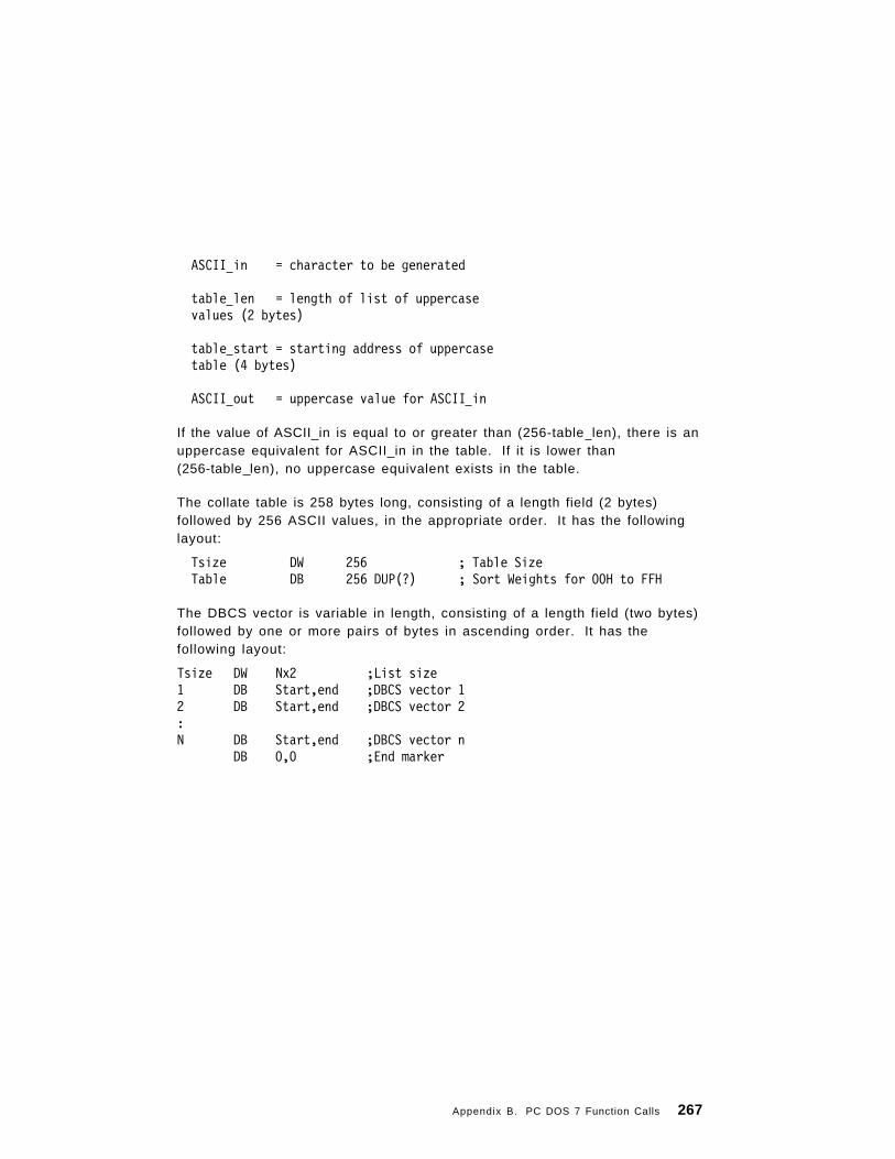
ASCII in = character to be generated
table len = length of list of uppercasevalues (2 bytes)
table start = starting address of uppercasetable (4 bytes)
ASCII out = uppercase value for ASCII in
If the value of ASCII in is equal to or greater than (256-table len), there is anuppercase equivalent for ASCII in in the table. If it is lower than(256-table len), no uppercase equivalent exists in the table.
The collate table is 258 bytes long, consisting of a length field (2 bytes)followed by 256 ASCII values, in the appropriate order. It has the followinglayout:
Tsize DW 256 ; Table SizeTable DB 256 DUP(?) ; Sort Weights for 00H to FFH
The DBCS vector is variable in length, consisting of a length field (two bytes)followed by one or more pairs of bytes in ascending order. It has thefollowing layout:
Tsize DW Nx2 ;List size1 DB Start,end ;DBCS vector 12 DB Start,end ;DBCS vector 2:N DB Start,end ;DBCS vector n
DB 0,0 ;End marker
Appendix B. PC DOS 7 Function Calls 267

66H — Get/Set Global Code Page
PurposeThis function gets or sets the code page for the current country.
MOV AX,6601H ; Function Call —; Get Global Code Page
INT 21H ; Issue request to DOSJC Error ; Error code in AXMOV GlobalCP,BX ; Save Global Code PageMOV SystemCP,DX ; Save DOS System Code Page
or
MOV AX,6602H ; Function Call —; Set Global Code Page
MOV BX,GlobalCP ; New Global Code PageINT 21H ; Issue request to DOSJC Error ; Error code in AX
----
GlobalCP DW ? ; Current Code Page of DOS Country InformationSystemCP DW ? ; Code Page of DOS messages
; Often the default Code Page for the; current country
CommentsPC DOS 7 moves the new code page data from the COUNTRY.SYS file to aresident country buffer area. PC DOS 7 uses the new code page to performa Select to all attached devices that are set up for code page switching, (thatis, have a code page switching device driver specified in CONFIG.SYS). Ifany device fails to be selected, an error code of 65 is returned in AX. Thecode page must be recognizable by the current country, and PC DOS 7 mustbe able to open and read from the country information file. Otherwise, thecarry flag will be set on return and AX will contain 02 (file not found).
Note: NLSFUNC must be installed to use this function call, and all thedevices must be prepared in order for the Select function to besuccessful.
268 PC DOS 7

67H — Set Handle Count
PurposePermits more than 20 open files per process.
ExamplesEntryPoint:
MOV AH,62H ; Function Call —; Get PSP Address
INT 21H ; Issue request to DOSJC Error ; Error code in AXMOV ES,BX ; Set SegmentMOV AH,4AH ; Function Call —
; Set Memory Block SizeMOV BX,paragraphs ; Set SizeINT 21H ; Issue request to DOSJC Error ; Error code in AXMOV AH,67H ; Function Call - Set Handle CountMOV BX,NewHandles ; Set new handle countINT 21H ; Issue request to DOSJC Error ; Error code in AX
----
NewHandles DW ? ; Number of Handles needed; by this PC DOS 7 process
ListSize EQU (Endofprogram - EntryPoint) ; Number of bytesParagraphs EQU (ListSize / 10H) ; Number of paragraphsEnd_of_program LABEL BYTE ; Last used position for
; this program
CommentsThe maximum number of file handles allowed for this interrupt is 64KB. Ifthe the specified number of allowable handles is less than the currentnumber allowed, the specified number will become current only after all thehandles above the specified number have been closed. If the specifiednumber is less than 20, the number is assumed to be 20. Data baseapplications can use this function to reduce the need to swap handles.
You must release memory for PC DOS 7 to contain the extended handle list.You can do this by using the SET BLOCK (4AH) function call.
Appendix B. PC DOS 7 Function Calls 269

68H — Commit File
PurposeCauses all buffered data for a file to be written to the device. This functioncan be used instead of a close-open sequence.
ExamplesMOV AH,68H ; Function Call — Commit FileMOV BX,Handle ; Select fileINT 21H ; Issue request to DOSJC Error ; Error code in AX
----
Handle DW ? ; Handle from previous Open or Create
CommentsCommit File provides a faster and more secure method of committing data inmulti-user environments such as the IBM PC Local Area Network Services.
270 PC DOS 7

6CH — Extended Open/Create
PurposeOptionally opens and creates a file.
ExamplesMOV AH,6CH ; Extended openMOV AL,0 ; ReservedMOV BX,MODE ; Open mode
; Format : 0WF00000ISSS0AAA; AAA=Access code 0=Read; 1=Write; 2=Read/Write; SSS=Sharing mode 0=Compatibility; 1=DenyRead/Write; 2=DenyWrite; 3=DenyRead; 4=DenyNone; I 0=Pass handle to child, 1=No inherit; F 0=INT 24H, 1=Return error; on this open and any I/O to this handle; W 0=No commit, 1=Auto-Commit on write
MOV CX,ATTR ; Create attribute (ignored if open)MOV DX,FLAG ; Function control, Format=0000000NNNNEEEE
; NNNN=Does not exist action; 0=Fail, 1=Create; EEEE=Exists action; 0=Fail, 1=Open, 2=Replace/Open
MOV SI,SEG file name ; Name to open or createMOV DS,SIMOV SI,OFFSET file nameINT 21HJC ERROR
; AX=Handle; CX=Action taken code; 1=File Opened; 2=File Created/Opened; 3=File Replaced/Opened
----Mode DW ? ; Open mode bit
; DefinitionsAttr DW ? ; File attributesFlag DW ? ; Function definitionFile name 64 DUP (0)
Appendix B. PC DOS 7 Function Calls 271

CommentsFunction 6CH combines the functions currently available with OPEN, CREATEand a CREATE NEW.
If F is 1, the critical error handler (Interrupt 24) is disabled for the handlereturned by Extended Open. Any I/O issued to this handle will nevergenerate the critical error but only the extended error.
If F is 0, no actions are taken.
If W is 1, any disk write using the handle returned by Extended Open willaccompany with a commit call (see Interrupt 21H (AL=68H)).
If W is 0, no actions are taken.
272 PC DOS 7

Appendix C. I/O Control for Devices (IOCtl)
PurposeSets or gets device information associated with open device handles, orsends control strings to the device handle or receives control strings fromthe device handle.
CommentsThe following function values are allowed in AL:
AL = 00H Get device information (returned in DX).AL = 01H Set device information (determined by DX). DH must be 0 for
this call.AL = 02H Read from character deviceAL = 03H Write to character deviceAL = 04H Read from block deviceAL = 05H Write to block deviceAL = 06H Get input statusAL = 07H Get output statusAL = 08H Determine if a particular block device is removableAL = 09H Determine if a logical device is local or remoteAL = 0AH Determine if a handle is local or remoteAL = 0BH Change sharing retry countAL = 0CH Issue handle generic IOCtl requestAL = 0DH Issue block device generic IOCtl requestAL = 0EH Get logical driveAL = 0FH Set logical driveAL = 10H QueryIOCtlHandleAL = 11H QueryIOCtlDevice
IOCtl can be used to get information about devices. You can make calls onregular files, but only function values 00H, 06H, and 07H are defined in thatcase. All other calls return an Invalid Function error.
Function values 00H to 08H are not supported on network devices. Functionvalue 0BH requires the file sharing command to be loaded (SHARE).
Many of the function calls return the carry flag clear if the operation wassuccessful. If an error condition was encountered, the carry flag is set; AXcontains an extended error code. (See “Extended Error Codes” on page 138in Appendix B for an explanation). An explanation of the error codes for call440CH can be located beginning on page 284 in this chapter. Information
Copyright IBM Corp. 1995 273

about the error, such as the error class, location, and recommended action,is obtained by issuing the 59H (Get Extended Error) function call.
44H — I/O Control for Devices (IOCtl)
Calls AL=00H and AL=01H
PurposeThese two calls set or get device information.
Examples
; To Get Device Information
MOV AH,44H ; Function Call — IOCtlMOV AL,0 ; Indicate get device informationMOV BX,Handle ; Select deviceINT 21H ; Issue request to DOSJC Error ; Error code in AXMOV DevInfo,DX ; Save device information
; To Set Device Information
MOV AH,44H ; Function Call — IOCtlMOV AL,1 ; Indicate set device informationMOV BX,Handle ; Select deviceMOV DX,DevInfo ; Device information to setXOR DH,DH ; All DH bits must be offINT 21H ; Issue request to DOSJC Error ; Error code in AX
-----
DevInfo DW ? ; Device informationHandle DW ? ; Handle to open device
274 PC DOS 7

CommentsThe bits of DevInfo are defined as follows:
│15│14│13│12│11│10│ 9│ 8│ 7│ 6│ 5│ 4│ 3│ 2│ 1│ 0│ ─┼──┼──┼──┼──┼──┼──┼──┼──┼──┼──┼──┼──┼──┼──┼──┼──┼─│R │ C│ │ I│ E│ B│ R│ I│ I│ I│ I││E │ T│ │ S│ O│ I│ E│ S│ S│ S│ S││S │ R│ Reserved │ D│ F│ N│ S│ C│ N│ C│ C│
│ │ L│ │ E│ │ A│ │ L│ U│ O│ I│ │ │ │ │ V│ │ R│ │ K│ L│ T│ N│ │ │ │ │ │ │ Y│ │ │ │ │ │─┼──┼──┼──┼──┼──┼──┼──┼──┼──┼──┼──┼──┼──┼──┼──┼──┼─
ISDEV = 1 if this channel is a device.
= 0 if this channel is a disk file (bits 8 through 15 are 0 in this case).
Bits 8 through 15 of DX correspond to the upper 8 bits of the devicedriver attribute word.
If ISDEV = 1
EOF = 0 if end-of-file on input.
BINARY = 1 if operating in binary mode(no checks for Ctrl-Z).
= 0 if operating in ASCII mode
(checking for Ctrl-Z as
end-of-file).
ISCLK = 1 if this device is the clock device.
ISNUL = 1 if this device is the null device.
ISCOT = 1 if this device is the console output.
ISCIN = 1 if this device is the console input.
CTRL = 0 if this device cannot process controlstr ings via cal ls AL=02H, AL=03H, AL=04H, and AL=05H.
CTRL = 1 if this device can process controlstrings via calls AL=02H and AL=03H.Note that this bit cannot be set byfunction call 44H.
If ISDEV = 0
EOF = 0 if channel has been written. Bits 0-5 are the block devicenumber for the channel (0 = A, 1 = B, ...). Bits 15, 8-13, 4 arereserved and should not be altered.
Appendix C. I/O Control for Devices (IOCtl) 275

Note: DH must be 0 for call AL=01H.
Calls AL=02H, AL=03H
PurposeThese two calls allow control strings to be sent or received from a characterdevice.
Examples
; To Read a Control String from a Character Device
MOV AH,44H ; Function Call — IOCtlMOV AL,2 ; Indicate IOCtl readMOV BX,Handle ; Select deviceMOV CX,SIZE Buffer ; Set size to readMOV DI,SEG Buffer ; Address I/O bufferMOV DS,DIMOV DX,OFFSET Buffer ; DS:DX points to I/O bufferINT 21H ; Issue request to DOSJC Error ; Error code in AXMOV Count,AX ; Save data read count
; To Write a Control String to a Character Device
MOV AH,44H ; Function Call — IOCtlMOV AL,3 ; Indicate IOCtl writeMOV BX,Handle ; Select deviceMOV CX,SIZE Buffer ; Set size to writeMOV DI,SEG Buffer ; Address I/O bufferMOV DS,DIMOV DX,OFFSET Buffer ; DS:DX points to I/O bufferINT 21H ; Issue request to DOSJC Error ; Error code in AXMOV Count,A X ; Save data written count
-----
Handle DW ? ; Handle to open device Buffer DB N DUP(?) ; I/O buffer Count DW ? ; Actual I/O data transfer count
276 PC DOS 7

CommentsThese are the Read and Write calls for a character device. An InvalidFunction error is returned if the CTRL bit is 0.
Calls AL=04H, AL=05H
PurposeThese two calls allow arbitrary control strings to be sent or received from ablock device.
Examples
; To Read a Control String from a Block Device
MOV AH,44H ; Function Call — IOCtlMOV AL,4 ; Indicate IOCtl readMOV BL,Drive ; Select driveMOV CX,SIZE Buffer ; Set Size to readMOV DI,SEG Buffer ; Address I/O bufferMOV DS,DIMOV DX,OFFSET Buffer ; DS:DX points to I/O bufferINT 21H ; Issue request to DOSJC Error ; Error code in AXMOV Count,AX ; Save data read count
; To Write a Control String to a Block Device
MOV AH,44H ; Function Call — IOCtlMOV AL,5 ; Indicate IOCtl writeMOV BL,Drive ; Select driveMOV CX,SIZE Buffer ; Set Size to writeMOV DI,SEG Buffer ; Address I/O bufferMOV DS,DIMOV DX,OFFSET Buffer ; DS:DX points to I/O bufferINT 21H ; Issue request to DOSJC Error ; Error code in AXMOV Count,AX ; Save data written count
-----
Drive DB ? ; Drive (0=current, 1=A:, 2=B:, ...)Buffer DB N DUP(?) ; I/O bufferCount DW ? ; Actual I/O data transfer count
Appendix C. I/O Control for Devices (IOCtl) 277

CommentsThese are the Read and Write calls for a block device. The drive number isin BL for these calls. An Invalid Function error is returned if the CTRL bit is0. An “Access-Denied” code is returned if the drive is invalid. The followingcontrol strings are defined for block device drivers that support media lock orunlock, and eject:
; Buffer to read drive status (use with IOCtl Read AL=04)
LockStatus STRUCStatus_Read db 6 ;Status Read Control block codeStatus_Bits dd ? ;Drive statusLockStatus ENDS
The Status_Bits on return, are interrupted as follows:
Bit 0 0 Door closed1 Door open
Bit 1 0 Door locked1 Door unlocked
Bits 2-31 0 Reserved (all zeros)
; Buffer to lock or unlock drive (use with IOCtl Write AL=05H)
LockCommand STRUCLock_Unlock db 1 ;Lock or unlock Control Block CodeCmd_Code db ? ;0 for unlock, 1 for lockLockCommand ENDS
; Buffer to eject media (use with IOCtl Write AL=05H)
EjectCommand STRUCEject db 0 ;Eject Control Block CodeEjectCommand Ends
Calls AL=06H and AL=07H
PurposeThese calls allow you to check if a handle is ready for input or output.
278 PC DOS 7

Examples; To Get Input Device Status
MOV AH,44H ; Function Call — IOCtlMOV AL,6 ; Indicate IOCtl input statusMOV BX,Handle ; Select deviceINT 21H ; Issue request to DOSJC Error ; Error code in AXMOV Status,AL ; Save status
; To Get Output Device Status
MOV AH,44H ; Function Call — IOCtlMOV AL,7 ; Indicate IOCtl output statusMOV BX,Handle ; Select deviceINT 21H ; Issue request to DOSJC Error ; Error code in AXMOV Status,AL ; Save status
-----
Handle DW ? ; Handle to open deviceStatus DB ? ; Status
; for a file:; 00H = At End of File; FFH = Not at End of File; for a device:; 00H = Not ready; FFH = Ready
CommentsIf used for a file, AL always returns F2H until end-of-file is reached, thenalways returns 00H unless the current file position is changed through call42H. When used for a device, AL returns FFH for ready or 0 for not ready.
Call AL=08H
PurposeThis call allows you to determine if a device can support removable media.
Appendix C. I/O Control for Devices (IOCtl) 279

Examples
MOV AH,44H ; Function Call — IOCtlMOV AL,8 ; Indicate IOCtl is removableMOV BL,Drive ; Select driveINT 21H ; Issue request to DOSJC Error ; Error code in AXMOV Dtype,AX ; Save type
-----
Drive DB ? ; Drive (0=current, 1=A:, 2=B:, ...)Dtype DW ? ; Drive type
; 0 = Drive is removable; 1 = Drive is fixed; 0FH = Drive not valid
CommentsIf the value returned in AX is 0, the device is removable. If the value is 1, thedevice is fixed. The drive number should be placed in BL. If the value in BLis invalid, an ″Access-Denied″ is returned. For network devices, the errorInvalid Function is returned.
Call AL=09H
PurposeThis call allows you to determine if a logical device is associated with anetwork directory.
Examples
MOV AH,44H ; Function Call — IOCtlMOV AL,9 ; Indicate IOCtl is remote driveMOV BL,Drive ; Select driveINT 21H ; Issue request to DOSJC Error ; Error code in AXTEST DX,1000H ; See if local/remoteJNZ Is_Remote ; Drive is remote
-----
Drive DB ? ; Drive (0=current, 1=A:, 2=B:, ...)
280 PC DOS 7

CommentsOn entry, BL contains the drive number of the block device you want tocheck (0=default, 1=A, 2=B, and so forth). The value returned in DXindicates whether the device is local or remote. Bit 12 is set for remotedevices (1000H). Bit 12 is not set for local devices. The other bits in DX arereserved. If disk redirection is paused, the function returns with bit 12 notset.
Call AL=0AH
PurposeThis call allows you to determine if a handle is for a local device or a remotedevice across the network.
Examples
MOV AH,44H ; Function Call — IOCtlMOV AL,0AH ; Indicate IOCtl is remote handleMOV BX,Handle ; Select device/fileINT 21H ; Issue request to DOSJC Error ; Error code in AXTEST DX,8000H ; See if local/remoteJNZ Is_Remote ; Drive is remote
-----
Handle DW ? ; Handle to open file or device
CommentsFor remote devices, bit 15 is set (8000H). The handle should be placed in BX.Bit 15 is not set for local devices.
Call AL=0BH
PurposeThis call controls retries on sharing and lock resource conflicts.
Appendix C. I/O Control for Devices (IOCtl) 281

Examples
MOV AH,44H ; Function Call — IOCtlMOV AL,0BH ; Indicate IOCtl set retry countsMOV CX,NumLoops ; Set number of loopsMOV DX,NumRetries ; Set number of retriesINT 21H ; Issue request to DOSJC Error ; Error code in AX
-----
NumLoops DW ? ; Number of times to execute loop belowNumRetries DW ? ; Number of times to retry on error
CommentsAll sharing and lock conflicts are automatically retried a number of timesbefore they are returned as a PC DOS 7 error or critical error. You canselect the number of retries and the delay time between retries. On input,CX contains the number of times to execute a delay loop, and DX containsthe number of retries. The delay loop consists of the following sequence:
XOR CX,CXLOOP $ ;spin 64K times
If this call is not issued, PC DOS 7 uses delay=1 and retries=3 as thedefaults for CX and DX. If you expect your application to cause sharing orlock conflicts on locks that are in effect for a short period of time, you maywant to increase the values for CX and DX to minimize the number of errorsactually returned to your application.
Call AL = 0CH
PurposeThis generic IOCtl function uses an open device handle to request a devicedriver to perform code page switching or to get/set device information.
Examples
MOV AH,44H ; Function Call — IOCtlMOV AL,0CH ; Indicate file handle generic IOCtl requestMOV BX,Handle ; Select device/fileMOV CH,Category ; Set device typeMOV CL,Function ; Set functionMOV DI,SEG Packet ; Address subfunction parameter packet
282 PC DOS 7

MOV DS,DIMOV DX,OFFSET Packet ; DS:DX points to parameter packetINT 21H ; Issue request to DOSJC Error ; Error code in AX
-----
Handle DW ? ; Handle to open file or deviceCategory DB ? ; Type of Device
; 0 - Unknown (if device type not known); 1 - a COMx device; 3 - CON; 5 - a LPTx device
Function DB ? ; Function within category; For category 3 & 5:; 4CH = Prepare start; 4DH = Prepare end; 4AH = Select (Set) code page; 6AH = Query (Get) selected code page; 6BH = Query prepare list; For Category 3:; 5FH = Set display information; 7FH = Get display information
Prepare Start: When CL=4CH, the parameter block, pointed to by DS:DX,has the following layout:
Packet Label WordPS_PACKET STRUC ; Prepare start packetPS_FLAGS DW 0 ; Control flags
; Bit 0 = 0 : Download prepare; BIT 0 = 1 : Cartridge prepare; Others reserved (set to 0)
PS_LENGTH DW (n+1)*2 ; Length of rest of packet in bytesPS_NUMCP DW n ; Number of code pagesPS_CP1 DW ? ; Code page 1
.
.
.
.PS_CPn DW ? ; Code page nPS_PACKET ENDS
Appendix C. I/O Control for Devices (IOCtl) 283

Notes:
1. Setting any PS CPn to -1 tells the device driver not to change the codepage value for that position. Any other value is a code page to beprepared.
2. n is the number of additional code pages specified in the DEVICE=command in CONFIG.SYS. The value for n can be up to 12.
3. For cartridge-prepares set the PS FLAGS field to 1.
A Prepare Start request begins the preparation of a code page. It is followedby writing data defining the code page font to the device driver using one ormore IOCtl write control string calls (AX=4403H). It is assumed that thisinformation will be downloaded to the device. The stream is ended by aPrepare End. The format of the stream is device dependent.
If the information is lost (due to a system failure or power-off), you do nothave to rewrite the prepared code page. Requesting a ″refresh″ operationby issuing a Prepare Start to the device driver with all code page values(PS CPn) set to a negative one (-1), restores the most recently preparedcode page information to the device. You must follow this operationimmediately with a Prepare End.
If no data is written for a prepare operation, the driver interprets the newlyprepared code page(s) as a hardware code page. This allows devices thatsupport user changeable hardware fonts (usually in cartridges) to besupported.
No prepare is needed for hardware-defined code pages.
Prepare Start Error Codes
Code Meaning01 Invalid function number22 Unknown command27 Code page conflict (used for KEYBxx mismatch)29 Device error31 Device driver does not have copy of code page to download to
device
Write Error Codes
Code Meaning27 Device not found in file, or code page not found in file29 Device error31 File contents not a font file, or file contents structure damaged
284 PC DOS 7

Prepare End: When CL=4DH the parameter block, pointed to by DS:DX, hasthe following layout:
Packet Label WordPE_PACKET STRUC ; Prepare end packetPE_LENGTH DW 2 ; Length of packet in bytesPE_RESV1 DW 0 ; (Reserved, must be 0)PE_PACKET ENDS
Prepare End Error Codes
Code Meaning19 Bad data read from font file31 No prepare start
Select/Query Selected Code Page: When CL=4AH or 6AH the parameterblock, pointed to by DS:DX, has the following layout:
PACKET LABEL WORD CP PACKET STRUC ; Select/Query Selected packet CP LENGTH DW 2+(n+1)*2 ; Length of packet in bytes CP CPID DW ? ; Code page ID CP VECTOR1 DB ?,? ; DBCS vector1
.
.
.CP VECTORn DB ?,? ; DBCS Vectorn
DB 0,0 ; End markerCP PACKET ENDS
Select/Query Selected Code Page also includes the DBCS environmentvector. Some device drivers may support only the code page value. As aresult, you must check the returned length when using this call to determineif the DBCS information is present. Only the drivers supplied with the Asianversion of PC DOS 7 provide this support.
Select Code Page Error Codes
Code Meaning26 Code page not prepared27 Current keyboard does not support this code page29 Device error
Query Selected Code Page Error Codes
Code Meaning26 No code page has been selected27 Device error
Appendix C. I/O Control for Devices (IOCtl) 285

Query Prepared List: When CL=6BH, the parameter block, pointed to byDS:DX, has the following layout:
PACKET LABEL WORDQL_PACKET STRUC ; Query list packetQL_LENGTH DW((m+1)+(n+1))*2 ; Length of packet in bytesQL_NUMHWCP DW n ; Number of hardware code pagesQL_HWCP1 DW ? ; Hardware code page 1
.
.
.
.QL_HWCPn DW ? ; Hardware code page nQL_NUMCP DW n ; Number of prepared code pagesQL_CP1 DW ? ; Prepared code page 1
.
.
.
.QL_CPm DW ? ; Prepared code page nQL_PACKET ENDS
Note: The device driver may return up to 12 code page values for each typeof code page (hardware or prepared) so n can be up to 12, and m canbe up to 12.
Query Prepared List Error Codes
Code Meaning26 No code pages have been selected29 Device error
Get/Set Display Information: When CL=5FH or 7FH, the parameter block,pointed to by DS:DX, has the following layout:
VP_PACKET STRUC ; Video parameters packetVP_LEVEL DB 0 ; Requested info level (set to 0 before IOCtl
; Call)VP_RESV1 DB 0 ; (Reserved, must be 0)VP_LENGTH DW 14 ; Length of rest of packet in bytesVP_FLAGS DW 0 ; Control flags
; Bit 0 = 0 : Intense colors; Bit 0 = 1 : Blink; Others reserved (set to 0)
VP_MODE DB ? ; Video mode; 1 = Text; 2 = APA; Others reserved
VP_RESV2 DB 0 ; (Reserved. must be 0)
286 PC DOS 7

VP_COLORS DW ? ; Number of colors (Mono=0)VP_WIDTH DW ? ; Display width in pixels (APA mode only)VP_LENGTH DW ? ; Display length in pixels (APA mode only)VP_COLS DW ? ; Display width in charactersVP_ROWS DW ? ; Display length in characters
VP_PACKET ENDS
Call AL = 0DH
PurposeThis generic IOCtl function requests a block device driver to perform one ofthe following subfunctions:
• Get device parameters• Set device parameters• Read track on logical device• Write track on logical device• Format and verify track on logical device• Verify track on logical device• Get access flag status• Set access flag status.
Examples
MOV AH,44H ; Function Call — IOCtlMOV AL,0DH ; Indicate Block Device Generic IOCtlMOV BL,Drive ; Select Device/FileMOV CH,Category ; Set Device TypeMOV CL,Function ; Set FunctionMOV DS,SEG Packet ; Address Subfunction Parameter PacketMOV DX,OFFSET PacketINT 21H ; Issue request to DOSJC Error ; Error code in AX
-----
Drive DB ? ; Drive (0=current, 1=A:, 2=B:, ...)Category DB ? ; Type of Device
; 8 - Block DeviceFunction DB ? ; Function within Category
; For Category 8:; 40H = Set device parameters; 60H = Get device parameters; 41H = Write track on logical device; 61H = Read track on logical device
Appendix C. I/O Control for Devices (IOCtl) 287

; 42H = Format and verify track on; logical device; 62H = Verify track on logical device; 47H = Set access flag; 67H = Get access flag; 68H = Get media type
Note: Functions 43H through 46H and functions 63H through 66H arereserved for the system.
CommentsCH contains the major code (08H for all functions) and CL contains the minorcode (function).
Get or Set Device ParametersTo Get Device Parameters, set CL = 60H.
To Set Device Parameters, set CL = 40H.
When CL = 60H or CL = 40H, the parameter block has the following fieldlayout:
Packet Label Byte A deviceParameters STRUC SpecialFunctions DB ? DeviceType DB ? DeviceAttributes DW ? NumberOfCylinders DW ? MediaType DB ? DeviceBPB a BPB <> TrackLayout a TrackLayout <> A deviceParameters ends
An explanation of each field in the parameter block is given in the pages thatfollow.
SpecialFunctions FieldThis 1-byte field is used to further define the Get and Set Device Parametersfunctions.
For the Get Device Parameters function, bit 0 of the SpecialFunctions fieldhas the following meaning:
Bit 0 =1 Return the BPB that BUILD BPB would return.=0 Return the default BPB for the device.
Note: All other bits must be off.
288 PC DOS 7

For the Set Device Parameters function bits 0, 1, and 2 of theSpecialFunctions field are used.
These bits have the following meanings when CL = 40H.
Bit 0 =1 All subsequent BUILD BPB requests return DeviceBPB . Ifanother Set Device request is received with bit 0 reset, BUILD BPBreturns the actual media BPB.=0 Indicates that the DeviceBPB field contains the new defaultBPB for this device. If a previous Set Device request set this biton, the actual media BPB is returned. Otherwise, the default BPBfor the device is returned by BUILD BPB.
Bit 1 =1 Ignore all fields in the Parameter Block except the TrackLayoutfield.=0 Read all fields of the parameter block.
Bit 2 =1 Indicates that all sectors in the track are the same size and allsector numbers are between 1 and n (where n is the number ofsectors in the track.)=0 Indicates that all sectors in the track may not be the same size.
Notes:
1. All other bits must be reset.
2. Set bit 2 for normal track layouts. Format Track can be more efficient ifbit 2 is set.
3. Setting bits 0 and 1 at the same time is invalid and should be consideredan error.
DeviceType FieldThis 1-byte field describes the physical device type. Device type is not set byIOCtl but is received from the device.
The values in this field have the following meanings:
0 = 320/360 KB 5.25 inch1 = 5.25 inch, 1.2 MB2 = 3.5 inch, 720 KB3 = 8-inch single-density4 = 8-inch double-density5 = Hard d isk6 = Tape dr ive7 = 3.5 inch, 1.44 MB8 = Read/Write Optical devices9 = 3.5 inch, 2.88 MB
Appendix C. I/O Control for Devices (IOCtl) 289
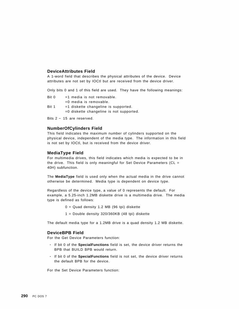
DeviceAttributes FieldA 1-word field that describes the physical attributes of the device. Deviceattributes are not set by IOCtl but are received from the device driver.
Only bits 0 and 1 of this field are used. They have the following meanings:
Bit 0 =1 media is not removable.=0 media is removable.
Bit 1 =1 diskette changeline is supported.=0 diskette changeline is not supported.
Bits 2 − 1 5 are reserved.
NumberOfCylinders FieldThis field indicates the maximum number of cylinders supported on thephysical device, independent of the media type. The information in this fieldis not set by IOCtl, but is received from the device driver.
MediaType FieldFor multimedia drives, this field indicates which media is expected to be inthe drive. This field is only meaningful for Set Device Parameters (CL =40H) subfunction.
The MediaType field is used only when the actual media in the drive cannototherwise be determined. Media type is dependent on device type.
Regardless of the device type, a value of 0 represents the default. Forexample, a 5.25-inch 1.2MB diskette drive is a multimedia drive. The mediatype is defined as follows:
0 = Quad density 1.2 MB (96 tpi) diskette
1 = Double density 320/360KB (48 tpi) diskette
The default media type for a 1.2MB drive is a quad density 1.2 MB diskette.
DeviceBPB FieldFor the Get Device Parameters function:
• If bit 0 of the SpecialFunctions field is set, the device driver returns theBPB that BUILD BPB would return.
• If bit 0 of the SpecialFunctions field is not set, the device driver returnsthe default BPB for the device.
For the Set Device Parameters function:
290 PC DOS 7

• If bit 0 of the SpecialFunctions field is set, the device driver is requestedto return the BPB from this field for all subsequent BUILD BPB requestsuntil a Set Device Parameters request is received with bit 0 in theSpecialFunctions field reset.
• If bit 0 is not set, the BPB contained in this field becomes the new defaultBPB for the device.
The DeviceBPB field has the following format:
a BPB STRUCBytesPerSector DW ?SectorsPerCluster DB ?ReservedSectors DW ?NumberOfFATs DB ?RootEntries DW ?TotalSectors DW ?MediaDescriptor DB ?SectorsPerFAT DW ?;SectorsPerTrack DW ?Heads DW ?HiddenSectors DD ?BigTotalSectors DD ?Reserved DB 6 Dup (0)a BPB ENDS
TrackLayout FieldThis is a variable length table indicating the expected layout of sectors onthe media track.
PC DOS 7 device drivers do not keep a track layout table for each logicaldevice. The global track table must be updated (by the Set DeviceParameters subfunction) when the attributes of the media change.
Note: The Set Device Parameters subfunction (CL=40H) modifies the tracktable regardless of how bit 1 of the SpecialFunctions field is set.
For Get Device Parameters, this field is not used. The track layout is used bysubsequent Read/Write Track, Format/Verify Track and Verify Trackfunctions.
The following example shows how this field is formatted:
Appendix C. I/O Control for Devices (IOCtl) 291

Total sectors-------|SectorCount DW n
Sector 1-----------|SectorNumber 1 DW 1H|SectorSize 1 DW 200H
Sector 2-----------|SectorNumber 2 DW 2H|SectorSize 2 DW 200H
Sector 3-----------|SectorNumber 3 DW 3H|SectorSize 3 DW 200H
Sector 4-----------|SectorNumber 4 DW 4H|SectorSize 4 DW 200H
|||
Sector n-----------|SectorNumber n DW n|SectorSize n DW 200H
Note: All values are in hexadecimal.
The total number of sectors is indicated by the SectorCount field. Each sectornumber must be unique and in a range between 1 and n (sector count). Asshown in the example above, the first sector number is 1 and the last sectornumber is equal to the sector count (n). If bit 2 of the SpecialFunctions fieldis set, all sector sizes, which are measured in bytes, must be the same.See the description of bit 2 under the SpecialFunction field.
Note: The DeviceType , DeviceAttributes , and NumberOfSectors fields shouldbe changed only if the physical device has been changed.
Read/Write Track on Logical DeviceTo read a track on a logical device, set CL = 61H.
To write a track on a logical device, set CL = 41H.
The parameter block has the following layout when reading or writing a trackon a logical device.
Packet LABEL BYTE a ReadWriteTrackPacket STRUC SpecialFunctions DB ? Head DW ? Cylinder DW ? FirstSector DW ? NumberOfSectors DW ? TransferAddress DD ?
292 PC DOS 7

A ReadWriteTrackPacket ENDS
Notes:
1. All bits in the SpecialFunctions field must be reset.
2. The value in the FirstSector field and the NumberOfCylinders field is0-based. For example, to indicate sector 9, set the value to 8.
Format/Verify Track on Logical Drive (IOCtl Write)To format and verify a track, set CL = 42H.
To verify a track, set CL = 62H.
The parameter block has the following layout when formatting a track orverifying a track on a logical drive.
PACKET LABEL BYTE A FormatPacket STRUC SpecialFunctions DB ? Head DW ? Cylinder DW ? A FormatPacket ENDS
On entry, bit 0 of the SpecialFunctions field has the following meanings:
Bit 0 = 1 Format status check call to determine if acombination of number-of-tracks andsectors-per-track is supported.
= 0 Format /Verify track call.
To determine if a combination of number-of-tracks and sectors- per-track issupported, a Set Device Parameters call must be issued with the correct BPBfor that combination before issuing the Format Status call. The device drivercan then return the correct code to indicate what is supported. The valuereturned in the SpecialFunctions field for a Format Status Check call are:
0 = This function is supported by theROM BIOS. The specified combination ofnumber-of-tracks and sectors-per-track isallowed for the diskette drive.
1 = This function is not supported bythe ROM BIOS.
Appendix C. I/O Control for Devices (IOCtl) 293

2 = This function is supported by theROM BIOS. The specified combination ofnumber-of-tracks and sectors-per-track isnot allowed for the diskette drive.
3 = This function is supported by theROM BIOS, but ROM BIOS cannot determineif the numbers-of-tracks andsectors-per-track are allowed becausethe diskette drive is empty.
To format a track:
1. Issue the Set Device Parameters function call.
2. Issue the Format Status Check function call to validate thenumber-of-tracks and sectors-per-track combination. Ignore the result ifthe value returned is 1, because the ROM BIOS does not support thisfunction.
3. Issue the Format/Verify Track function call with the SpecialFunctions bit 0reset for each track on the medium.
Get/Set AccessFlag StatusTo get the access flag status of a hard disk, set CL=67H.
To set the access flag status of a hard disk, set CL=47H.
The parameter block has the following layout when getting or setting theaccess flag status of a hard disk:
PACKET LABEL BYTEa DiskAccess Control STRUCSpecialFunctions DB 0DiskAccess Flag DB ? ; 0 = Disallow disk access
; Other value = allow disk accessa DiskAccess Control ENDS
If the media has not been formatted or has an invalid boot record, the systemwill not allow disk I/O for the media. This ensures data integrity of fixedmedia. Since formatting a media is a special activity, and is needed toperform disk I/O for unformatted media, additional functions to control thedisk access flag are necessary. A format utility should issue ″Set the accessflag status (CL=47H)″ with DiskAccess Flag = non-zero value to access theunformatted media. When every format operation is a success, leave theaccess flag status as it is to allow further disk I/O from general users. If
294 PC DOS 7

format fails, issue ″Set the access flag status (CL = 47H)″ withDiskAccess Flag = zero in order to block further media access. To get thecurrent status of the system disk access flag, issue ″Get the access flagstatus (CL = 67H)″. If DiskAccess Flag = zero, disk I/O is not allowed forthe media.
Get/Set Media IDTo get the media ID, set CL=66H.
To set the media ID, set CL=46H.
The parameter block has the following layout when getting and setting themedia ID:
PACKET LABEL BYTEMedia_ID_Packet STRUC Info_Level DW 0 ; Information level,
; currently always 0 Serial DD ? ; Volume serial number Label DB 11 dup (′ ′ ) ; Volume label from
; boot record File_Sys_Type DB 8 dup (′ ′ ) ; File system type Media_ID_Packet ENDS
Get Media ID copies the information from the boot record into theMedia_ID_Packet. Set Media ID copies the information from theMedia_ID_Packet to the boot record. If the disk does not contain a validBPB, or the signature field is missing, then no action is taken, and bothfunctions return Unknown Media (error code 7).
Get Media Type (PC DOS 7)To get the media type, set CL=68H.
The parameter block has the following layout:
PACKET LABEL BYTEMedia_Type_Packet STRUC Default DB ? ; 1 if media is equal or equivalent
; to the capacity of the drive.; 0 if media is less than; the capacity of the drive.
Media_Type DB ? ; Media Type:; 2 for 720KB 3.5-inch 80-track floppy; 7 for 1.44MB 3.5-inch 80-track floppy; 9 for 2.88MB 3.5-inch 80-track floppy
Reserved_1 DB ? ; Reserved Reserved_2 DD ? ; Reserved
Appendix C. I/O Control for Devices (IOCtl) 295

Media_Type_Packet ENDS ?
CommentsIf carry is set, then the error return code is in AX. Otherwise, carry iscleared.
Call AL = 0EH Get Logical Drive Map
PurposeThis call allows the device driver to determine if more than one logical driveis assigned to a block device. When this call is issued, a drive number ispassed in BL on input.
Examples
MOV AH,44H ; Function Call — IOCtlMOV AL,0EH ; Indicate Logical Drive CheckMOV BL,Drive ; Select DriveINT 21H ; Issue request to DOSJC Error ; Error code in AXCMP AL,0 ; Only one drive letter for this device?JE Single_Drive ; Yes!MOV ActiveDrive,AL ; Save Active Drive info
-----
Drive DB ? ; Drive (0=current, 1=A:, 2=B:, ...)ActiveDrive DB ? ; Current drive letter for this device
; (1=A:, 2=B:, ...)
CommentsIf the block device has more than one logical drive letter assigned to it, onoutput a drive number corresponding to the last drive letter that was used toreference the device is returned in AL. If only one drive letter is assigned tothe device, 0 is returned in AL by this call.
296 PC DOS 7

Call AL = 0FH Set Logical Drive Map
PurposeThis call requests the device driver to change the next logical drive letterthat will be used to reference a block device.
Examples
MOV AH,44H ; Function Call — IOCtlMOV AL,0FH ; Indicate Set Logical DriveMOV BL,Drive ; Set DriveINT 21H ; Issue request to DOSJC Error ; Error code in AXCMP AL,0 ; Only one drive letter for this device?JE Single_Drive ; Yes!MOV ActiveDrive,AL ; Save Active Drive info
; (should be the same as BL in)
-----
Drive DB ? ; Drive (0=current, 1=A:, 2=B:, ...)ActiveDrive DB ? ; Current drive letter for this device
; (1=A:, 2=B:, ...)
CommentsWhen copying diskettes on a drive whose physical drive number has morethan one logical drive letter assigned to it (for example, copying on a singledrive system), PC DOS 7 issues diskette swap prompts to tell you whichlogical drive letter is currently referencing the physical drive number. As thedrive changes from source to target, PC DOS 7 issues the message: Insertdiskette for drive X: and strike any key when ready.
It is possible to avoid this message by issuing call AL = 0FH (Set LogicalDrive).
To avoid the PC DOS 7 diskette swap message, set BL to the drive numberthat corresponds to the drive letter that will be referenced in the next I/Orequest.
Note: You can determine the last logical drive letter assigned to the physicaldrive number by issuing call AL = 0EH.
Appendix C. I/O Control for Devices (IOCtl) 297

Because any block device can have logical drives, this call should be issuedbefore all I/O operations involving more than one drive letter; otherwise, thePC DOS 7 message may be issued.
Call AL = 10H Query IOCTL Handle
PurposeQueryIOCtlHandle accepts a device handle and determines whether aspecific IOCtl capability is supported by the device.
Examples
MOV AH,44H ; Function Call — IOCtlMOV AL,10H ;MOV BX,handle ; Select device/fileMOV CH,category ; Category functionMOV CL,function ; Packet filled in for function
; to be testedMOV DX,offset packetINT 21H ; Issue request to DOSJC Error ; Error code in AX
CommentsCategory, function, and parameter block are filled in as they would be for thefunction whose presence is being checked for.
Upon exit, if carry is set, the error code in AL will be 1 for “Function notsupported.” If carry is not set, then AX = 0.
This function call is supported by DOS 5.0 device drivers.
Call AL = 11H Query IOCTL Device
PurposeQueryIOCtlDevice accepts a drive number and determines whether a specificIOCtl capability is supported by the drive.
298 PC DOS 7

Examples
MOV AH,44H ; Function Call — IOCtlMOV AL,11H ;MOV BL,drive ; Select driveMOV CH,category ; Category functionMOV CL,function ; Packet filled in for function
; to be testedMOV DX,offset packetINT 21H ; Issue request to DOSJC Error ; Error code in AX
CommentsCategory, function, and parameter block are filled in as they would be for thefunction whose presence is being checked for.
Upon exit, if carry is set, the error code in AL will be 1 for “Function notsupported.” If carry is not set, then AX = 0.
This function call is supported by DOS 5.0 device drivers.
Appendix C. I/O Control for Devices (IOCtl) 299

300 PC DOS 7

Appendix D. Expanded Memory Support
Expanded memory is memory addressable through a combination of anExpanded Memory Specification (EMS) device driver and an EMS-capablehardware adapter or via a 386 memory manager.
The table below lists the Lotus/Intel/Microsoft (LIM) Expanded MemoryManager Specification Version 4.0 functions.
LIMFunction
INT 67H Interface Description
1 AH = 40H Basic Get status2 AH = 41H Basic Get page frame address3 AH = 42H Basic Get unallocated page count4 AH = 43H Basic Allocate pages5 AH = 44H Basic Map/unmap handle page6 AH = 45H Basic Deallocate pages7 AH = 46H Basic Get EMM version8 AH = 47H Advanced Save page map9 AH = 48H Advanced Restore page map10 Reserved11 Reserved12 AH = 4BH Advanced Get EMM Handle count13 AH = 4CH Advanced Get EMM Handle pages14 AH = 4DH Advanced Get all EMM handle pages15 AH = 4EH Advanced Get/Set page map16 AH = 4FH Advanced Get/Set partial page map17 AH = 50H Advanced Map/Unmap multiple handle pages18 AH = 51H Advanced Reallocate pages19 AH = 52H Advanced Get/Set handle attributes20 AH = 53H Advanced Get/Set handle name21 AH = 54H Advanced Get handle directory22 AH = 55H Advanced Alter page map and jump23 AH = 56H Advanced Alter page map and call24 AH = 57H Advanced Move/Exchange memory region25 AH = 58H Advanced Get mappable physical address
array26 AH = 59H Advanced Get expanded memory hardware
information27 AH = 5AH Advanced Allocate new pages28 AH = 5BH Advanced Alternate page map register set29 AH = 5CH Advanced Prepare expanded memory
hardware for warm boot30 AH = 5DH Advanced Enable/Disable Operating System
Environment function set
Copyright IBM Corp. 1995 301

The following pages only outline the basic functions of the Expanded MemorySpecification, these functions being the ones useful to applicationdevelopers.
For information on the advanced functions, more detailed information andguidelines on the use of these calls, refer to the Expanded MemorySpecification published by Lotus/Intel/Microsoft.
302 PC DOS 7

Function 1 — Get Status
PurposeThis function returns the status that tells you whether the EMM386 is presentand if the hardware is working correctly. This function does not require apreviously opened EMM handle.
Examples
MOV AH, 40H ; Function to Get StatusINT 67H ; Call Interrupt 67HOR AH, AHJNZ error_handler
----
CommentsA return code of 0 in the AH register is for a successful call. The following isa list of other possible codes.
AH Description
00H The memory manager is loaded and the hardware is working.80H The manager detected a problem in the EMM software.81H The manager detected a problem in the expanded memory
hardware.84H The function code passed to the EMM is not defined.
Appendix D. Expanded Memory Support 303

Function 2 — Get Page Frame Address
PurposeThis function informs your program where the page frame is located. Itreturns the segment portion of the page frame address in the BX register.This function does not require a previously opened EMM handle.
ExamplesMOV AH, 41H ; Get Page Frame Address functionINT 67H ; Call interrupt 67HOR AH, AHJNZ error_handler
MOV Page_Segment, BX----Page_Segment DW ? ; Page Segment Address
CommentsA return code of 0 in the AH register is for a successful call. The following isa list of other possible codes.
The BX register contains the segment address of the page frame. The valuein BX has no significance if AH is not equal to 0.
AH Description
00H The memory manager is loaded and the hardware is working.80H The manager detected a problem in the EMM software.81H The manager detected a problem in the expanded memory
hardware.84H The function code passed to the EMM is not defined.
304 PC DOS 7
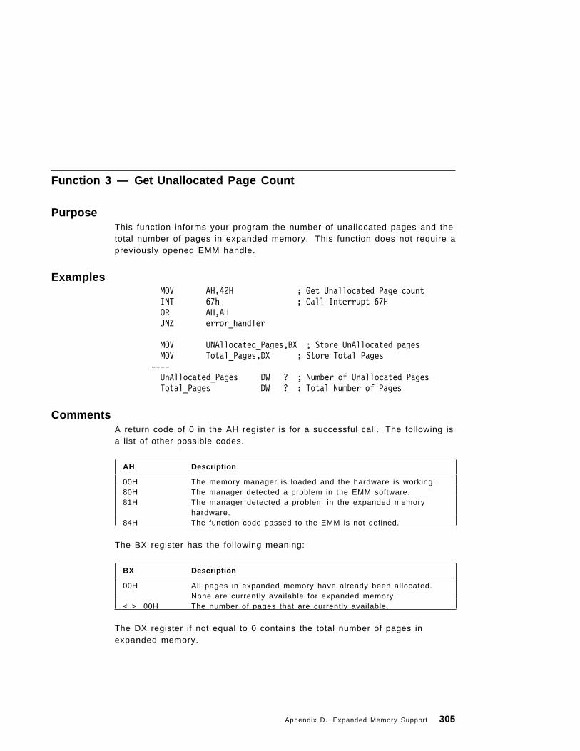
Function 3 — Get Unallocated Page Count
PurposeThis function informs your program the number of unallocated pages and thetotal number of pages in expanded memory. This function does not require apreviously opened EMM handle.
ExamplesMOV AH,42H ; Get Unallocated Page countINT 67h ; Call Interrupt 67HOR AH,AHJNZ error_handler
MOV UNAllocated_Pages,BX ; Store UnAllocated pagesMOV Total_Pages,DX ; Store Total Pages
----UnAllocated_Pages DW ? ; Number of Unallocated PagesTotal_Pages DW ? ; Total Number of Pages
CommentsA return code of 0 in the AH register is for a successful call. The following isa list of other possible codes.
The BX register has the following meaning:
The DX register if not equal to 0 contains the total number of pages inexpanded memory.
AH Description
00H The memory manager is loaded and the hardware is working.80H The manager detected a problem in the EMM software.81H The manager detected a problem in the expanded memory
hardware.84H The function code passed to the EMM is not defined.
BX Description
00H All pages in expanded memory have already been allocated.None are currently available for expanded memory.
< > 00H The number of pages that are currently available.
Appendix D. Expanded Memory Support 305

Function 4 — Allocate Pages
PurposeThis function allocates the number of pages your program requests andassigns a unique EMM handle to these pages. The EMM handle ″owns″these pages until your program later deallocates them.
ExamplesMOV AH,43H ; Allocated Pages FunctionMOV BX,Number_Pages ; Number of Pages to AllocateINT 67H ; Call Interrupt 67HOR AH,AHJNZ error_handler
MOV EMM_Handle, DX ; Store EMM Handle----Number_Pages DW ? ; Number of Pages to AllocateEMM_Handle DW ? ; EMM Handle
CommentsThe status is returned in register AH and has the following meanings:
The DX register contains a unique EMM handle. The program must use thisEMM handle (as a parameter) in any subsequent function calls that map ordeallocate expanded memory.
AH Description
00H The manager has allocated the pages to an assigned EMMhandle.
80H The manager detected a problem in the EMM software.81H The manager detected a problem in the expanded memory
hardware.84H The function code passed to the EMM is not defined.85H All of the EMM handles are being used.87H There is not enough expanded memory pages to satisfy your
program ′s request.88H There is not enough unallocated pages to satisfy your
program ′s request.89H Can not allocate zero pages.
306 PC DOS 7

Function 5 — Map Handle Page
PurposeThis function lets your program access the information stored in a logicalpage at a physical page within the page frame.
ExamplesMOV DX,EMM_Handle ; Previously Opened EMM Handle
; (Function 4 - Allocate Pages)MOV BX,Logical_Page ; Logical Page in the Physical
; Page Within the Page Frame; Range is 0 to total pages; allocated to a Handle -1
MOV AL,Physical_Page ; Range is 0 to 3MOV AH,44H ; function to Map Handle PageINT 67H ; Call Interrupt 67HOR AH, AHJNZ error_handler
CommentsThe function returns one of the following status codes:
AH Description
00H The manager has mapped the page. The page is now ready tobe accessed.
80H The manager detected a problem in the EMM software.81H The manager detected a problem in the expanded memory
hardware.83H Invalid EMM handle specified.84H The function code passed to the EMM is not defined.8AH The logical page is out of range of the logical pages which are
allocated to this EMM handle.8BH The physical page at which the logical page was supposed to be
mapped is out of the range of physical pages.
Appendix D. Expanded Memory Support 307

Function 6 — Deallocate Pages
PurposeThis function deallocates the pages currently allocated to an EMM handle.After your program invokes this function, other application programs can usethese pages.
Warning
Your program should invoke this function before it exits to DOS. If it doesnot, other programs may not use these pages or their handle.
ExamplesMOV DX, EMM_handle ; Previously Opened EMM Handle
; (Function 4 - Allocate Pages)MOV AH, 45h ; Deallocate Pages FunctionINT 67h ; Call Interrupt 67HOR AH, AHJNZ error_handler
CommentsThe following status is returned in the AH register:
AH Description
00H The manager has deallocated the pages previously allocated tothe EMM handle.
80H The manager detected a problem in the EMM software.81H The manager detected a problem in the expanded memory
hardware.83H Invalid EMM handle specified.84H The function code passed to the EMM is not defined.86H The EMM detected a ″save″ or ″restore″ page mapping context
error (FUNCTION 8 or 9). There is a page mapping registerstate in the ″save area″ for the EMM handle specified. SavePage Map (FUNCTION 8) placed it there and it has not beenremoved by a subsequent Restore Page Map (FUNCTION 9).
You need to restore the contents of the page mapping registerbefore you deallocate the EMM handle ′s page(s).
308 PC DOS 7

Function 7 — Get EMM Version
PurposeThis function returns the version number of the Expanded Memory Managersoftware.
ExamplesMOV AH,46HINT 67HOR AH,AHJNZ error_handler
MOV EMM_Version,AL ; Store Version Information
CommentsThe function returns one of the following status values:
The AL register contains the Expanded Memory Manager′s version numberin Binary Coded Decimal. The upper four bits in the AL register contain theinteger digit (3.x) of the version number. The lower four bits in the ALregister contain the fractional digit of (x.2) version number. The valuecontained in AL has no importance if AH is not equal to 0.
AH Description
00H The manager is present in the system and the hardware isworking correctly.
80H The manager detected a problem in the EMM software.81H The manager detected a problem in the expanded memory
hardware.84H The function code passed to the EMM is not defined.
Appendix D. Expanded Memory Support 309

Detecting the Expanded Memory ManagerIn this brief section we show an example of how you may detect thepresence of an installed Expanded Memory Manager. The first method usesthe DOS INT 21H function 3DH (Open a File), which is used to open a file ordevice.
The EMM driver is opened using its name EMMXXXX0, if the open issuccessful, it means that either an EMM driver is installed or that a filenamed EMMXXXX0 exists on the default drive and directory. The latter caseis unlikely, but you should check for the possibility. This is done by usingDOS INT 21H function 44H, subfunction 07H (IOCtl, Get Output Status). Thehandle returned from the Open File function is used with the IOCtl, GetOutput Status - this subfunction checks the output status of a device that isassociated with a handle. If the return of this subfunction is 00H, then thedevice is actually a disk file and EMM is not installed or available. If thereturn is FFH then the opened handle is associated with a Expanded MemoryManager.
The following is an example of using the above technique:
ExamplesEMM_Device_Name DB ″EMMXXXX0″-----
PUSH DSPUSH CSPOP DSMOV AH,3DH ; Open File Function CallMOV DX,EMM_Device_Name ; Set ASCII Name in DXMOV AL, 0H ; Open file in read only modeINT 21H ; Call Interrupt 21HJC Open_Device_Error
MOV EMM_Handle,AX ; Save file handle
MOV DX, Buffer ;MOV BX, EMM_HandleMOV CX, 0H ;MOV AX,44H ; IOCtl function 44HMOV AL,07H ; Subfunction 07 Get Output StatusINT 21H ; Call Interrupt 21H
MOV Status,AX
MOV BX,EMM_Handle ;
310 PC DOS 7

MOV AH,3EH ; Close File HandleINT 21H ; Call Interrupt 21H
The second method of detecting the Expanded Memory Manager is by usingthe address that may be found in the 67H interrupt vector. The 67H interruptis of course the one used by the EMM driver, this interrupt 67H vectorcontains the address location of the driver. By normal convention thememory location at an offset of 0AH in the EMM drivers code segmentcontains the device driver name, EMMXXXX0 (in our case). If the name ispresent at the location specified then the EMM driver is installed.
The following is an example of using the above technique:
ExamplesEMM_Device_name DB ″EMMXXXX0″----
MOV AH,35H ; Get Interrupt vectorMOV AL,67H ; EMM Interrupt numberINT 21H ; Call Interrupt 21H
MOV DI,0AH ; Segment is in ES, set the; offset in DI
LEA SI, EMM_Device_Name; Offset of EMM name in SI
MOV CX,08 ; EMM String Name size in CXCLD ; Compare the names for a matchREPECMPSBJNE Error_Exit
Appendix D. Expanded Memory Support 311

312 PC DOS 7

Appendix E. DOS Protected Mode Services
The following section describes the DOS Protected Mode Services (DPMS)driver that is provided along with PC DOS 7. The driver is written by Novell**and is used by the Stacker** compression driver.
The DPMS driver makes its services available to DPMS clients via interrupts2FH and 31H. In this section are briefly described the 2FH Multiplex Interruptcall that are provided if the DPMS driver is installed and the Interrupt 31Hcalls.
For more detailed information please refer to the DOS Protected ModeServices specifications from Novell.
Interrupt Function Description
2FH AX=43E0H DPMS Installation Check
31H AX=0100H Call Protected-Mode Procedure
31H AX=0101H Call Real-Mode Procedure (RETF)
31H AX=0102H Call Real-Mode Procedure (IRET)
31H AX=0103H Call Real-Mode Interrupt Handler
31H AX=0200H Allocate Descriptors
31H AX=0201H Free a Descriptor
31H AX=0202H Create Alias Descriptor
31H AX=0203H Build Alias to Real-Mode Segment
31H AX=0204H Set Descriptor Base
31H AX=0205H Set Descriptor Limit
31H AX=0206H Set Descriptor Type/Attribute
31H AX=0207H Get Descriptor Base
31H AX=0300H Get Size of Largest Free Block of Memory
31H AX=0301H Allocate Block of Extended Memory
31H AX=0302H Free Block of Extended Memory
31H AX=0303H Map Linear Memory
31H AX=0304H Unmap Linear Memory
31H AX=0400H Relocate Segment to Extended Memory
Copyright IBM Corp. 1995 313
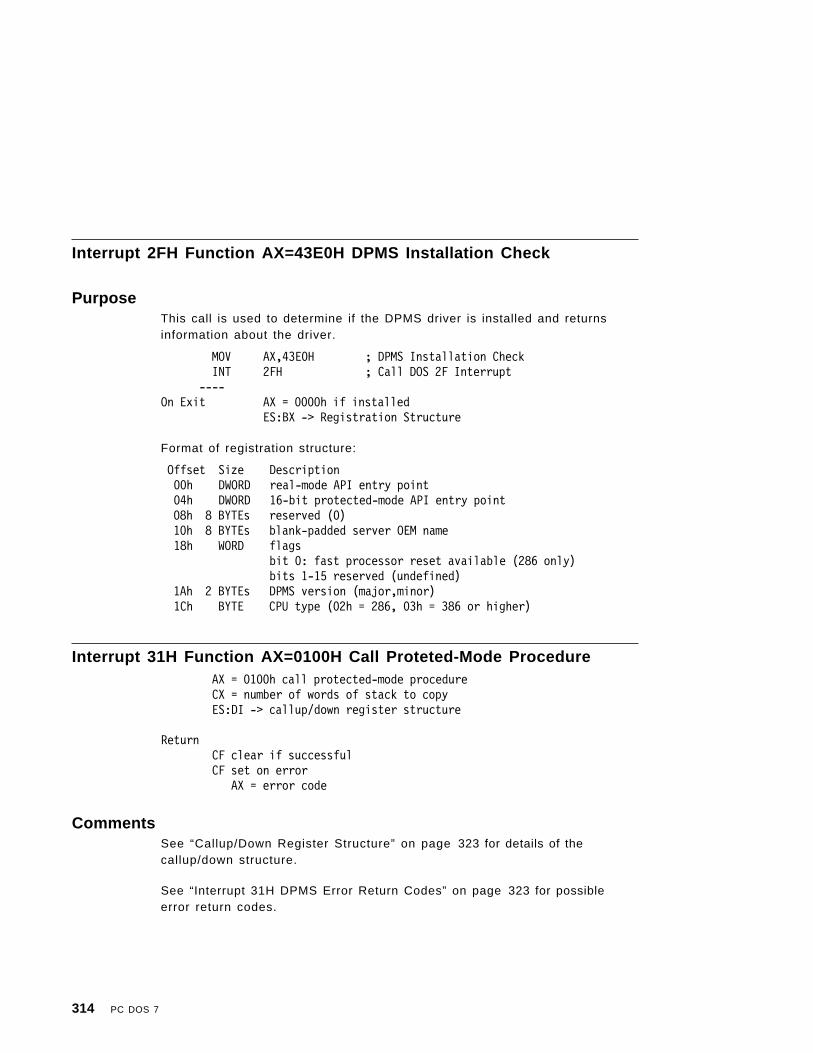
Interrupt 2FH Function AX=43E0H DPMS Installation Check
PurposeThis call is used to determine if the DPMS driver is installed and returnsinformation about the driver.
MOV AX,43E0H ; DPMS Installation CheckINT 2FH ; Call DOS 2F Interrupt
----On Exit AX = 0000h if installed
ES:BX -> Registration Structure
Format of registration structure:
Offset Size Description00h DWORD real-mode API entry point04h DWORD 16-bit protected-mode API entry point
08h 8 BYTEs reserved (0) 10h 8 BYTEs blank-padded server OEM name18h WORD flags
bit 0: fast processor reset available (286 only)bits 1-15 reserved (undefined)
1Ah 2 BYTEs DPMS version (major,minor)1Ch BYTE CPU type (02h = 286, 03h = 386 or higher)
Interrupt 31H Function AX=0100H Call Proteted-Mode ProcedureAX = 0100h call protected-mode procedureCX = number of words of stack to copyES:DI -> callup/down register structure
ReturnCF clear if successfulCF set on error
AX = error code
CommentsSee “Callup/Down Register Structure” on page 323 for details of thecallup/down structure.
See “Interrupt 31H DPMS Error Return Codes” on page 323 for possibleerror return codes.
314 PC DOS 7

Interrupt 31H Function AX=0101H Call Real-Mode Procedure (RETF)AX = 0101h call real-mode procedure (RETF return)CX = number of words of stack to copyES:DI -> callup/down register structure
ReturnCF clear if successfulCF set on error
AX = error code
CommentsSee “Callup/Down Register Structure” on page 323 for details of thecallup/down structure.
See “Interrupt 31H DPMS Error Return Codes” on page 323 for possibleerror return codes.
Interrupt 31H Function AX=0102H Call Real-Mode Procedure (IRET)AX = 0102h call real-mode procedure (IRET return)CX = number of words of stack to copyES:DI -> callup/down register structure
ReturnCF clear if successfulCF set on error
AX = error code
CommentsSee “Callup/Down Register Structure” on page 323 for details of thecallup/down structure.
See “Interrupt 31H DPMS Error Return Codes” on page 323 for possibleerror return codes.
Appendix E. DOS Protected Mode Services 315

Interrupt 31H Function AX=0103H Call Real-Mode Interrupt Handler
PurposeThis function call transfers control to the address specified by the real-modeinterrupt vector.
AX = 0103h call real-mode interrupt handlerBL = interrupt numberCX = number of words of stack to copyES:DI -> callup/down register structure
ReturnCF clear if successfulCF set on error
AX = error code
CommentsSee “Callup/Down Register Structure” on page 323 for details of thecallup/down structure.
See “Interrupt 31H DPMS Error Return Codes” on page 323 for possibleerror return codes.
Interrupt 31H Function AX=0200H Allocate Descriptors
PurposeThis function allocates one or more descriptors in the task′s local descriptortable. The descriptors allocated must be initialized by the application.
AX = 0200h allocate descriptorsCX = number of descriptors to allocate
ReturnCF clear if successful
AX = first descriptor allocatedCF set on error
AX = error code
316 PC DOS 7

CommentsSee “Interrupt 31H DPMS Error Return Codes” on page 323 for possibleerror return codes.
Interrupt 31H Function AX=0201H Free a Descriptor
PurposeFrees a previously allocated descriptor.
AX = 0201h free a descriptorBX = descriptor
ReturnCF clear if successfulCF set on error
AX = error code
CommentsSee “Interrupt 31H DPMS Error Return Codes” on page 323 for possibleerror return codes.
Interrupt 31H Function AX=0202H Create Alias Descriptor
PurposeCreates a new descriptor that has the same base and limit as the specifieddescriptor.
AX = 0202h create alias descriptorBX = descriptor
ReturnCF clear if successful
AX = alias descriptorCF set on error
AX = error code
Appendix E. DOS Protected Mode Services 317

CommentsSee “Interrupt 31H DPMS Error Return Codes” on page 323 for possibleerror return codes.
Interrupt 31H Function AX=0203H Build Alias to Real-Mode Segment
PurposeAX = 0203h build alias to real-mode segmentBX = descriptorCX = real-mode segment
ReturnCF clear if successfulCF set on error
AX = error code
CommentsSee “Interrupt 31H DPMS Error Return Codes” on page 323 for possibleerror return codes.
Interrupt 31H Function AX=0204H Set Descriptor BaseAX = 0204h set descriptor baseBX = descriptorCX:DX = base address
ReturnCF clear if successfulCF set on error
AX = error code
CommentsSee “Interrupt 31H DPMS Error Return Codes” on page 323 for possibleerror return codes.
318 PC DOS 7

Interrupt 31H Function AX=0205H Set Descriptor LimitAX = 0205h set descriptor limitBX = descriptorCX = limit
ReturnCF clear if successfulCF set on error
AX = error code
CommentsSee “Interrupt 31H DPMS Error Return Codes” on page 323 for possibleerror return codes.
Interrupt 31H Function AX=0206H Set Descriptor Type/AttributeAX = 0206h set descriptor type/attributeBX = descriptorCL = typeCH = attribute
ReturnCF clear if successfulCF set on error
AX = error code
CommentsSee “Interrupt 31H DPMS Error Return Codes” on page 323 for possibleerror return codes.
Interrupt 31H Function AX=0207H Get Descriptor BaseAX = 0207h get descriptor baseBX = descriptor
ReturnCF clear if successfulCX:DX = base addressCF set on error
AX = error code
Appendix E. DOS Protected Mode Services 319

CommentsSee “Interrupt 31H DPMS Error Return Codes” on page 323 for possibleerror return codes.
Interrupt 31H Function AX=0300H Get Size of Largest Free Block ofMemory
AX = 0300h get size of largest free block of memory
ReturnCF clear if successful
BX:CX = sizeCF set on error
AX = error code
CommentsSee “Interrupt 31H DPMS Error Return Codes” on page 323 for possibleerror return codes.
Interrupt 31H Function AX=0301H Allocate Block of Extended MemoryAX = 0301h allocate block of extended memoryBX:CX = size
ReturnCF clear if successful
BX:CX = base addressSI:DI = handle
CF set on errorAX = error code
CommentsSee “Interrupt 31H DPMS Error Return Codes” on page 323 for possibleerror return codes.
Interrupt 31H Function AX=0302H Free Block of Extended MemoryAX = 0302h free block of extended memorySI:DI = handle
ReturnCF clear if successfulCF set on error
320 PC DOS 7

AX = error code (see below)
CommentsSee “Interrupt 31H DPMS Error Return Codes” on page 323 for possibleerror return codes.
Interrupt 31H Function AX=0303H Map Linear MemoryAX = 0303h map linear memoryES:[DI] = DDS
ReturnCF clear if successful
BX:CX = base addressSI:DI = handle
CF set on errorAX = error code
CommentsSee “Interrupt 31H DPMS Error Return Codes” on page 323 for possibleerror return codes.
Interrupt 31H Function AX=0304H Unmap Linear MemoryAX = 0304h unmap linear memorySI:DI = handle
ReturnCF clear if successfulCF set on error
AX = error code
CommentsSee “Interrupt 31H DPMS Error Return Codes” on page 323 for possibleerror return codes.
Appendix E. DOS Protected Mode Services 321

Interrupt 31H Function AX=0400H Relocate Segment to ExtendedMemory
AX = 0400h relocate segment to extended memoryES:SI = base addressCX = limitBL = typeBH = attributeDX = selector or 0000h
Return: CF clear if successfulAX = selectorBX:CX = new base addressSI:DI = handle
CF set on errorAX = error code
CommentsSee “Interrupt 31H DPMS Error Return Codes” on page 323 for possibleerror return codes.
322 PC DOS 7

Interrupt 31H DPMS Error Return Codes
Table 2. DPMS Error Return Codes
AX Description
8000H General error8001H Unsupported function8011H Descriptor unavailable8012H Linear memory unavailable8013H Physical memory unavailable8021H Invalid value8022h Invalid selector8023H Invalid handle
Callup/Down Register StructureThe following is the format for the callup/down register structure that is usedwith interrupt 31H, function calls 0100H, 0101H, 0102H and 0103H.
Offset Size Description00H DWORD EDI04H DWORD ESI08H DWORD EBP
0CH 4 BYTEs Reserved (0) 10H DWORD EBX 14H DWORD EDX 18H DWORD ECX 20H DWORD EAX 24H DWORD EIP28H WORD CS
2AH 2 BYTEs Reserved (0) 2CH DWORD EFLAGS 30H DWORD ESP34H WORD SS
36H 2 BYTEs Reserved (0)38H WORD ES
3AH 2 BYTEs Reserved (0)3CH WORD DS
3EH 2 BYTEs Reserved (0)40H WORD FS
42H 2 BYTEs Reserved (0)44H WORD GS
46H 2 BYTEs Reserved (0)
Appendix E. DOS Protected Mode Services 323

324 PC DOS 7

Appendix F. Task-swapping
The user-shell introduced with DOS 5.0 provides a task-swapper function.With it the user can switch from one application to another withoutterminating either application. When a user starts a new program, thetask-swapper suspends the currently-active program (in this case, thesession-manager program) saves the contents of all registers, and writes thecontents of the program memory to disk or to where “SET TEMP=” isspecified. A new session is then created by the loading and executing of thenew program. (A session is a program that is executed directly by thetask-swapper and runs independently of other sessions.) The task-swapperremains active, normally monitoring the keyboard for a predefined keysequence. When the user presses the key sequence, the task-swappersuspends and saves the current session and transfers control to the formerlysuspended session. It reads the memory contents of another suspendedsession into system memory, sets up the registers with the saved values,and transfers control to the formerly suspended session.
Most application programs can be suspended without problems. Becausethey execute synchronously, they can be interrupted in mid-execution andrestarted (if the task-swapper properly saves and restores the state of thesystem that was in effect when it suspended the program). Some types ofprograms cannot operate safely with a task-swapper. For example:
• Some terminate-stay-resident (TSR) programs. (These arememory-resident programs that are executed asynchronously.) That is,they execute and take control of the system independently of theforeground program, the main program in control of the system. Anetwork utility which performs tasks ″in the background″ while theforeground application is inactive is an example of this type of program.If a program with an outstanding network read request is suspended andreplaced with another program, the network utility can copy therequested data into the second program ′s context. This data canoverwrite code or data used by the second program, causing a systemmalfunction.
• Some types of mainframe communications software. Mainframecommunication software is normally communicating with software onanother system.
• Software that maintains separate data for each process running on thesystem (a process is any program running within a session). Oneexample of this type of software is a network redirector which traps DOSfunction calls to provide access to a simulated drive, but which does notuse internal data structures maintained by DOS. While a task-swapper
Copyright IBM Corp. 1995 325

might adjust these data structures during a session switch, a redirectorwhich does not rely on these tables must be able to maintain thisinformation by itself. Consequently, the redirector must be notified of asession switch and must be able to prevent or delay the switch until itcan handle the switch properly.
The DOS task-swapping protocol gives this type of software the ability tocoexist with task-swappers that conform to the protocol. The protocolspecifies a standard method of communication between the task-swapperand other software on the system, and gives software that would beadversely affected by a session switch the opportunity to control the timing ofa switch or to prevent it altogether. Finally, the protocol provides a standardmethod for task-swappers to cooperate with each other, minimizing theproblems that would result when competing task-swappers exist on thesystem simultaneously. Programs which conform to the DOS Task-swappingProtocol can coexist safely with the task-swappers incorporated in DOS 5.0and later, and in future versions of Windows** running in real and standardmodes.
Windows running in 386 enhanced mode is a preemptive, multitaskingsystem. For this reason, it has a different set of requirements than swappersthat do not support multitasking.
To be ″safe″ in both task-swapping and multitasking environments, clientsand task-swappers must support both types of environments. This appendixdescribes the requirements for safe operation in a task-swappingenvironment. However, programs that are to run safely in a multitaskingenvironment must also use the Windows 386 enhanced mode Int 2FHinterface and are likely to require a specialized Windows 386 enhanced modevirtual device. These programs may need also to maintain separate instancedata for task-swapper sessions and for virtual devices.
For more information on the Windows 386 enhanced mode virtual devicesand the Int 2FH interface, see the Microsoft Windows Device Driver Kit VirtualDevice Adaptation Guide.
The DOS task-swapping protocol specifies a standard method fortask-swappers and other programs so they can cooperate with each other.Task-swappers and other types of programs exist in a client/serverrelationship in which the task-swapper is the server and other programs actas clients. This chapter uses the term client to refer to a program thatconforms to this protocol and is not a task-swapper. As noted above, most
** Windows is a trademark of the Microsoft Corporation.
326 PC DOS 7
task-swappers work by suspending one session, moving that session to adisk or to extended or expanded memory, and then loading anotherapplication in the same address space. However, in most systems there areother areas of memory, such as memory occupied by DOS, device drivers,and TSR utilities that are not swapped. In nearly every case, the programsthat occupy this memory were started before the task-swapper, and arerunning and accessible regardless of which application the task-swapper hasloaded into system memory. These type programs are referred to as globalsoftware. Memory that remains unchanged through task switches is calledglobal memory. Local memory, on the other hand, is memory associatedwith a session spawned by the task-swapper. When the task-swapper swapsthe session, this memory is swapped to disk or to extended or expandedmemory.
Client InitializationOne of the first responsibilities of the task-swapper is to add itself to thechain of Int 2FH handlers by calling the Get Interrupt Vector Int 21H function(AH = 35H) and the Set Interrupt Vector Int 21H function (AH = 25H). After aclient program has installed itself in the interrupt chain, it must determinewhether a task-swapper is already present by calling the Detect swapper Int2FH call-in function. If a task-swapper is present, the function returns withthe call-in address of the task-swapper in ES:DI. Using the call-in address inES:DI, the client must call the Hook Call-Out call-in function to allow thetask-swapper to add the client′s call-out function handler address to thechain of call-out handlers it is maintaining for the session in which the clientis running.
The Client Int 2FH HandlerThe task-swapper issues an Int 2FH to call two client functions, the BuildCall-Out Chain function and the Identify Instance Data function. Both of thesefunctions are called by the task-swapper to build a linked list of datastructures. Depending on the function, each structure identifies a particularclient′s call-out function handler address or a client ′s instance data. Ingeneral, the client Int 2FH handler performs the following tasks to add itsstructure to the list:
1. The Int 2FH handler determines whether AX contains a value identifying atask-swapper call-out function. If not, it transfers control to the previousInt 2FH handler with a far jump.
2. If AX identifies a task-swapper call-out function, the Int 2FH handlerpushes the flags and makes a far call to the previous Int 2FH handler.
Appendix F. Task-swapping 327

3. When the call returns, the Int 2FH handler places the value in ES:BX (theaddress of the previous handler′s data structure) in the appropriate fieldof the client′s data structure.
4. The Int 2FH handler places the address of the client′s own data structurein ES:BX and returns from the interrupt. The specific actions taken by theInt 2FH handler and the data structure used depends on the particular Int2FH call-out function.
Responding to a Pending Session SwitchMost clients must be able to prevent a session switch from occurring whenthe client or other software is in an unstable state during which a sessionswitch could result in the loss or corruption of data.
A task-swapper calls two call-out functions before performing a sessionswitch. The Query Suspend function provides notification to affected clientsthat the task-swapper is preparing to suspend the currently active session.When a client receives a call to this function, it can either perform whateveroperations are required and then allow the session switch to proceed, or itcan prevent the session switch altogether.
The task-swapper calls the Suspend Session call-out function of each client ifno client fails the Query Suspend call. Since interrupts were enabled whilethe task-swapper was making the Query Suspend call, the system state couldhave changed after a given client had received the call. The SuspendSession call provides clients one last opportunity to prevent the sessionswitch. Since the task-swapper calls this function with interrupts disabled,the system state is guaranteed not to change following the Suspend Sessioncall until the session switch takes place. For this reason interrupts mustremain disabled until all clients have returned from the call. Also, a clientmust not issue software interrupts or use calls that might enable interrupts.The client can only return zero in AX to permit the session switch or one toprevent the session switch. All other registers must be preserved.
A client must not fail a Query Suspend or Suspend Session call because anasynchronous API is being executed without first determining that theapplications program interface (API) is not being handled by more competentsoftware. The client determines this by calling the Query API Support call-infunction.
If any client fails the Query Suspend or Suspend Session calls, all clients inthe entry-point chain called by the task-swapper may receive a SessionActive call for the session that was to be suspended. For this reason it ispossible to receive a Session Active call for a session that has not beensuspended or activated. Clients can safely ignore these calls.
328 PC DOS 7

If no client fails the Suspend Session call, the task-swapper replaces thecurrent interrupt vector table with a saved copy before enabling interrupts.The saved copy represents the global state present when the task-swapperwas first started. This guarantees that interrupt handlers local to the sessionbeing suspended are not called until the session is resumed.
Between the Suspend Session call and the next Activate Session callinterrupts are enabled intermittently and global software can receiveinterrupts during this time. Global clients must not assume the contents ofany nonglobal memory between Suspend Session and Activate Session calls.
The task-swapper calls the Activate Session call-out function of affectedclients to notify them that a task is about to be resumed. It then calls theSession Active function when the previously suspended session has beenloaded into memory (including its local memory and interrupt vector table)and interrupts have been enabled.
Responding to the Pending Creation of a New SessionJust as a client can prevent a session switch, a client also can prevent thetask-swapper from creating a new session. Before creating the new session,the task-swapper calls the Create Session call-out function. A client can takethe appropriate action to prepare for the new session (for example, allocatingadditional memory to hold information for the session) and then permit thetask-swapper to create the new session. Or the client can fail the CreateSession call to block the new session from being created. A client wouldprevent a new session from being created, for example, if it maintainedsession-data in a fixed-length buffer that was too full to accommodateanother session.
If any client fails the Create Session call, the task-swapper calls the DestroySession function of some or all clients. The Destroy Session function notifiesclient programs that the session ID passed with the Create Session call is nolonger valid. Since the task-swapper may call all clients or only those clientsthat had received the Create Session call, it is possible to receive a DestroySession call for a session that has not been created or activated. Clients cansafely ignore this Destroy Session call.
If no client fails the Create Session call, the task-swapper usually suspendsthe current session and then calls the Activate Session function by using aflag set to notify clients that the new session is about to take control. Thisgives clients the opportunity to take whatever action is required to preparefor the new session. The task-swapper then calls the Session Active (againwith a flag set) to notify clients that the new session has been started.However, because some session managers (such as Windows) permit the
Appendix F. Task-swapping 329

user to start a session in an inactive state, the Activate Session and SessionActive calls might not occur immediately after the Create Session call. Othersessions might also be activated and suspended before the newly createdsession becomes active for the first time, if at all.
Client TerminationBefore terminating, a client must perform two tasks:
• It must call the Unhook Call-Out call-in function. This removes its call-outfunction handler from the chain of local call-out handlers maintained bythe task-swapper.
• The client must remove its Int 2FH handler from the chain of Int 2FHhandlers by calling the Set Interrupt Vector Int 21H function (AH = 25H),replacing the Int 2FH interrupt vector with the address of the previous Int2FH handler (saved when the client was initialized).
The Switch_Call_Back_Info Data StructureEvery client must maintain a Switch_Call_Back_Info (SCBI) data structure.The client supplies this structure to the task-swapper when calling orresponding to several different functions. The SCBI structure containsinformation about the entry point of the client′s call-out function handler anda pointer to a list of API_Info_Struc data structures. These structures specifythe types of asynchronous API which the client supports and the level ofsupport it is able to provide. The Switch_Call_Back_Info data structure isdefined as follows:
Switch_Call_Back_Info STRUCSCBI_Next dd ? ; address of next structure in chainSCBI_Entry_Pt dd ? ; address of notification function handlerSCBI_Reserved dd ?SCBI_API_Ptr dd ?
Switch_Call_Back_Info ENDS
The Switch_Call_Back_Info structure contains the following fields:
• SCBI_Next − This 32-bit value contains a pointer to the next structure inthe client chain. A task-swapper calls the Build Call-Out Chain Int 2FHcall-out function to build this chain.
• SCBI_Entry_Pt − This 32-bit value contains a pointer to the entry point ofthe client′s call-out function handler.
• SCBI_Reserved − This 32-bit value is reserved for use by thetask-swapper.
330 PC DOS 7

• SCBI_API_Ptr − This 32-bit value contains a segment:offset pointer to azero-terminated list of API_Info_Struc data structures. These structuresspecify the type of support the client provides for various asynchronousAPIs.
The API_Info_Struc Data StructureThe API_Info_Struc (AIS) data structure contains information about the levelof support that a client provides to a particular type of asynchronous API.The API_Info_Struc structure is defined as follows:
API_Info_Struc STRUC
AIS_Length dw 10AIS_API dw ?AIS_Major_Ver dw ?AIS_Minor_Ver dw ?AIS_Support_Level dw ?
API_Info_Struc ENDS
The API_Info_Struc data structure contains the following fields:
1. AIS_Length − This 16-bit value specifies the length of the AIS datastructure.
2. AIS_API − This 16-bit value specifies the ID of the asynchronous APIsupported by the client. The following values are defined:
API_NETBIOS equ 1 ; NETBIOS
API_8022 equ 2 ; 802.2
API_TCPIP equ 3 ; TCP/IP
API_LANMAN equ 4 ; LAN Manager named pipes
API_IPX equ 5 ; NetWare IPX
• AIS_Major_Ver − This 16-bit value specifies the highest major version ofthe API for which the client provides the level of support specified by theAIS_Support_Level field. For example, if the highest version of the APIsupported by the client at the specified level is 3.10, this field would beset to 3h.
• AIS_Minor_Ver − This 16-bit value specifies the highest minor version ofthe API for which the client provides the specified level of support. For
Appendix F. Task-swapping 331

example, if the highest version of the API supported by the client at thespecified level is 3.10, this field would be set to Ah.
• AIS_Support_Level − This 16-bit value specifies the level of supportprovided by the client for the particular version of the API. The rangeand significance of values in this field depends upon the particular API.The following definitions are used for NETBIOS:
− Minimal support. The client prevents a session switch after theapplication has executed any asynchronous API, even after therequest has been completed.
− API-level support. The client tracks asynchronous requests that areoutstanding and prevents task switches at those times. The clientallows task switches after all outstanding asynchronous requestshave completed.
− swapper compatibility. The API provider allows switches to occureven when asynchronous requests are outstanding. However, thismight be limited by such factors as buffer size, and some requestsmight fail.
− Seamless compatibility. The API provider always allows sessionswitches to occur, and this never causes loss of data.
The Win386_Startup_Info_Struc Data StructureThe Win386_Startup_Info_Struc data structure is defined as follows:
Win386_Startup_Info_Struc STRUC
SIS_Version db 3,0 ; ignoredSIS_Next_Dev_Ptr dd ? ; Ptr to previous handler′ s
; Win386_Startup_Info_StrucSIS_Virt_Dev_File_Ptr dd 0 ; ignoredSIS_Reference_Data dd ? ; ignoredSIS_Instance_Data_Ptr dd ? ; Ptr to IIS structures
Win386_Startup_Info_Struc ENDS
The Win386_Startup_Info_Struc is the same structure used to respond to theMicrosoft Windows startup Int 2FH function. However, the DOS task-swapperuses only the SIS_Next_Dev_File_Ptr and SIS_Instance_Data_Ptr fields. (Forinformation on the other fields, see the Microsoft Windows Device Driver KitVirtual Device Adaptation Guide.)
The Win386_Startup_Info_Struc data structure contains the following fields:
• SIS_Version − This two-byte field is not used.
332 PC DOS 7

• SIS_Next_Dev_Ptr − This 32-bit value contains a segment:offset pointerto the next structure in the client chain. See below for more informationabout how this chain is constructed.
• SIS_Virt_Dev_File_Ptr − This 32-bit field is not used.
• SIS_Reference_Data − This 32-bit field is not used.
• SIS_Instance_Data_Ptr − This 32-bit value contains a segment:offsetpointer to a list of Instance_Item_Struc data structures. Each structuredescribes one contiguous block of instance data. The list is terminatedby a 32-bit zero value.
The Instance_Item_Struc Data StructureThe Instance_Item_Struc data structure is defined as follows:
Instance_Item_Struc STRUC
IIS_Ptr dd ?IIS_Size dw ?
Instance_Item_Struc ENDS
The Instance_Item_Struc structure contains the following fields:
• IIS_Ptr − This 32-bit value contains a segment:offset pointer to the firstbyte of the block of instance data. IIS_Size − This 16-bit value specifiesthe size, in bytes, of the block of instance data.
The Swapper_Ver_StructureThe following shows the definition of the Swapper_Ver_Struc data structure:
Swapper_Ver_Struc STRUC
SVS_API_Major dw ?SVS_API_Minor dw ?SVS_Product_Major dw ?SVS_Product_Minor dw ?SVS_swapper_ID dw ?SVS_Flags dw ?SVS_Name_Ptr dd ?SVS_Prev_Swapper dd ?
Swapper_Ver_Struc ENDS
The Swapper_Ver_Struc contains the following fields:
Appendix F. Task-swapping 333
• SVS_API_Major − This 16-bit value specifies the highest major version ofthe Task-swapping Protocol that the swapper supports. For example, ifthe highest version of the protocol supported by the client at thespecified level is 3.10, this field would be set to AH. The current versionis 1.0.
• SVS_API_Minor − This 16-bit value specifies the highest minor versionof the Task-swapping Protocol that the swapper supports. For example, ifthe highest version of the protocol supported by the task-swapper is 3.10,this field would be set to AH. The current version is 1.0.
• SVS_Product_Major − This 16-bit value specifies the major version of thetask-swapper, in the same format as SVS_API_Major.
• SVS_Product_Minor − This 16-bit value specifies the minor version of thetask-swapper, in the same format as SVS_API_Minor.
• SVS_Swapper_ID − This 16-bit field specifies, in its low-order four bits,the swapper ID value obtained from the Allocate swapper ID function.
• SVS_Flags − This 16-bit field contains a bit-array of 16 bits used as flags.In this version of the Task-swapping Protocol, only bit 0 is used. If theswapper is currently disabled, bit 0 is set. Otherwise, bit 0 is clear.
• SVS_Name_Ptr − This 32-bit value contains a segment:offset pointer to azero-terminated ASCII string that identifies the task-swapper (forexample, ″DOS Shell Task-swapper″).
• SVS_Prev_Swapper − This 32-bit value contains the address (insegment:offset form) of the previously loaded swapper′s call-out functionentry point that is returned by the Detect swapper Int 2FH task-swapperfunction.
Function DescriptionsThis section describes the Int 2FH handler functions, task-swapper call-outfunctions, and task-swapper call-in functions that comprise the DOSTask-swapping Protocol. The function descriptions are grouped according tothese categories. Within each category the function descriptions aredescribed in numeric order. Each function description is headed by thename of the function followed by a brief description of the function and therequired conditions at the entry and exit of the function. Optional commentsappear following the entry and exit information.
Note: All registers not used by these functions must be preserved.
334 PC DOS 7

Task-swapper Int 2FH Handler FunctionsCurrently there is one Int 2FH function for the task-swapper. It is specifiedbelow:
Detect Swapper (Function 4B02H)A client calls the Detect Swapper Int 2FH function to determine if atask-swapper is currently running and to obtain the address of its call-in (tothe task-swapper) function entry point.
Example:
MOV AX,04B02H ;Detect presence of a task-swapperXOR BX,BX ;Required for future extensibilityXOR DI,DIMOV ES,DIINT 2FH
;;Save call-out address to the current task-swapper;
MOV WORD PTR OUT_TO_SWAPPER+0, DIMOV WORD PTR OUT_TO_SWAPPER+2, ES
--------
OUT_TO_SWAPPER DD 0 ; Call-out address to the currenttask-swapper
All other registers are preserved.
Comments
A non-NULL pointer returned in ES:DI indicates the presence of atask-swapper. AX is returned with zero for future extensibility and the carryflag is clear.
Clients call this function during initialization and take the appropriate action ifa swapper is detected.
Client Int 2FH Handler FunctionsA client that is in full compliance with this protocol must contain an Int 2FHhandler that can properly respond to the Build Call-Out Chain function(4B01H) from the task-swapper. In addition, it must also respond to theIdentify Instance Data function (4B05H) if the client maintains data for eachsession. The following sections describe these functions.
Appendix F. Task-swapping 335

Build Call-out ChainThis Client Int 2FH Handler function links a client′s call-out function entrypoint to a chain of client call-out entry points on the swapper.
On Entry:; Respond to Call_Out function from task-swapper
cmp ax,04b01h ;Build Chain Call-in function?jnz Pass_Function_Ontest Bit_flag,00000001bjnz Pass_Function_On;;ES:BX = 0:0 for future extensibility;CX:DX = call-in address of the calling task-swapper;
pushfcall far Prev_Int2f_Handler;ES:BX = 0:0 if the first client loaded in memory
;mov offset SCBI_Next,bxmov offset SCBI_Next+2,es
Back_to_swapper:
or Bit_flag,1 ;We′ ve been heremov bx,offset Swap_Call_Back_Infomov es,cs;;All other registers must be preserved.;
iret
Pass_Function_On:;
jmp far Prev_Int2f_Handler
--------
Bit_flag db 0 ; bit 1 = 0 if not called by swapper; = 1 if called by the swapper
Comments
ES:BX = 0:0 if you are first client loaded in-memory
336 PC DOS 7

A task-swapper calls this function to create a linked list of the call-outfunction entry points of all global clients, clients running in the currentsession, and of information about the asynchronous APIs supported by eachclient. When the function returns, ES:BX contains a pointer to the client′sSCBI data structure containing this information.
Swap_Call_Back_Info STRUC
SCBI_Next dd ? ;pointer to next structure in listSCBI_Entry_Pt dd ? ;CS:IP of entry point procedureSCBI_Reserved dd ? ;used by the swapperSCBI_API_Ptr dd ? ;pointer to list of API structures
Swap_Call_Back_Info ENDS
For a description of the SCBI data structure, see “The Switch_Call_Back_InfoData Structure” on page 330 in this manual for a description of this structure.
When a client receives an Int 2FH, it checks AX to determine whether the Int2FH is calling a Client Int 2FH Handler function. If not, the client passescontrol to the previous Int 2FH handler using a far jump. If it is, the Client Int2FH Handler routine immediately pushes the flags and call the previous Int2FH vector using a far call. It does not modify any registers before makingthe call.
When the call returns, ES:BX will contain the address of the previous client′sSCBI data structure (or 0:0 if the current client was the first loaded intomemory). Whether or not ES:BX is 0:0, the value in ES:BX is placed in theSCBI_Next field of the client′s SCBI data structure. The client then places theaddress of its SCBI data structure into ES:BX and then returns from theinterrupt.
When the call returns to the calling task-swapper, ES:BX points to the SCBIdata structure of the last client loaded into memory. As a result, the SCBIdata structures of the most recently loaded clients appear near the head ofthe chain. Consequently, the most recently loaded clients will be calledbefore clients that were loaded earlier. This would allow, for example, anapplication with outstanding asynchronous requests to cancel the requestwhen a session swap is about to occur before the network is queried. If thecalls were to occur in the reverse order, the network might block the sessionswap because of the outstanding asynchronous requests.
At the entry to the Build Call-in Chain function, CX:DX contains the call-infunction entry point of the calling task-swapper. A client can call this routine,with arguments specifying the function to be performed, while it is handling
Appendix F. Task-swapping 337

the Int 2FH call. However, the address passed in the Int 2FH call may not bethe same address made available in later call-out function calls.
Identify Instance DataThis Client Int 2FH Handler function identifies instance data maintained bythe client. For example:
On Entry:; Respond to Call_Out function from task-swapper for Instance Data
cmp ax,04b05h ;Build Chain Call-in function?jnz Pass_Function_On;;ES:BX = 0:0 for future extensibility;CX:DX = call-in address of the calling task-swapper;Calls to DOS can be made
;Make call to previous client′ s Win386_Startup_Info_Struc; data structure;
pushfcall far Prev_Int2f_Handler
mov offset SIS_Next_Dev_Ptr,BXmov offset SIS_Next_Dev_Ptr+2,ES
Back_to_swapper:;;Provide Win386_Startup_Info_Struc data structure address;
mov bx,offset Win386_Startup_Info_Strucpush cspopiret ;All other registers must be preserved
Pass_Function_On:jmp far Prev_Int2f_Handler ;to previous Int 2FH handler
--------
Win386_Startup_Info_Struc STRUC
SIS_Version db 3,0 ; ignoredSIS_Next_Dev_Ptr dd ? ; Ptr to previous handler′ s
; Win386_Startup_Info_StrucSIS_Virt_Dev_File_Ptr dd 0 ; ignored
338 PC DOS 7

SIS_Reference_Data dd ? ; ignoredSIS_Instance_Data_Ptr dd ? ; Ptr to IIS structures
Win386_Startup_Info_Struc ENDS
Comments
A task-swapper calls this function to create a linked list of instance datablocks of all clients running on the system.
When a client receives an Int 2FH, it checks AX to determine whether the Int2FH is calling a Client Int 2FH Handler function. If it is not, the client passescontrol to the previous Int 2FH handler by using a far jump. If it is, the clientInt 2FH handler routine immediately pushes the flags and call the previousInt 2FH vector using a far call. It does not modify any registers before makingthe call.
When the call returns, ES:BX will contain the address of the previous client′sWin386_Startup_Info_Struc data structure (or 0:0 if the current client was thefirst loaded into memory). Whether or not ES:BX is 0:0, the value in ES:BX isplaced in the SIS_Next_Dev_Ptr field of the client′s Win386_Startup_Info_Strucdata structure. The client then places the address of itsWin386_Startup_Info_Struc data structure into ES:BX and returns from theinterrupt.
When the call returns to the calling task-swapper, ES:BX points to theWin386_Startup_Info_Struc data structure of the last client loaded intomemory.
Task-swapper Call-In FunctionsThe DOS task-swapper is in full compliance with this protocol and contains acall-in function entry point that can properly respond to the following sevenfunctions:
• Get Version (Function 0H)
• Test Memory Region (Function 1H)
• Hook Call-out (Function 4H)
• Unhook Call-out (Function 5H)
• Query API Support (Function 6H)
The following sections describe these functions.
Appendix F. Task-swapping 339

Note: All task-swapper call-in functions return with the carry flag clear. If acall-in function returns with the carry flag set, the function is notimplemented by the receiving task-swapper.
Get VersionThis task-swapper call-in function identifies the current task-swapper, itsversion number, and the level of the task-swapping Protocol that it supports.
For Example:
MOV AX,0 ;Get Version call to the task-swapperCLI ;Interrupts disabledCALL OUT_TO_SWAPPER ;From Detect swapper Int 2FH, AX=4b02h
;;AX = 0 for future extensibility;All other registers are preserved.;;Save address of the swapper′ s Version; Data structure;
MOV SWAPPER_VER_STRUC_PTR+0,BXMOV SWAPPER_VER_STRUC_PTR+2,ES
--------
SWAPPER_VER_STRUC_PTR DD 0
Comments
The following shows the definition of the Swapper_Ver_Struc data structure.
Swapper_Ver_Struc STRUC
SVS_API_Major dw ?SVS_API_Minor dw ?SVS_Product_Major dw ?SVS_Product_Minor dw ?SVS_Swapper_ID dw ?SVS_Flags dw ?SVS_Name_Ptr dd ?SVS_Prev_Swapper dd ?
Swapper_Ver_Struc ENDS
For a description of the Swapper_Ver_Struc data structure, see “TheSwapper_Ver_Structure” on page 333 in this manual.
340 PC DOS 7

Test Memory RegionThis task-swapper call-in function is used to identify global or local memorylocations to the current session. Memory that is global is not replaced whena task-swap occurs.
For Example:
MOV AX,1 ;Test memory region call-out to the; task-swapper
MOV DI,OFFSET BUFFER ;Address of buffer to be testedMOV ES,SEG_BUFFER ;ES is the buffer′ s segment addressMOV CX,BUFFER_LENGTH ;Length of buffer in bytes (0 to 65535)
; where 0 indicates 64K bytes (65536)CLI ;Interrupts disabledCALL OUT_TO_SWAPPER ;Obtained from Detect Swapper
; Int 2FH, AX=4b02h;;Carry flag is clear
MOV REGION_LOCATION,AX;AX = 0, Buffer is in global memory;AX = 1, Buffer is partially in global; and partially in local memory;AX = 2, Buffer is in local memory;;All other bits are reserved and must be 0;All other registers are preserved.
Comments
If the buffer to be tested is longer than 64K bytes, more than one call isrequired to test the entire region. The determination whether memory isglobal or local is performed by the current task-swapper. Clients check thestatus of memory following each Query Suspend or Session Active call todetermine whether the memory is global or local to the task-swapperperforming the session swap.
Global software can use this function to identify asynchronous calls comingfrom another layer of global software. In these cases, the global softwarewould not have to take special action when a session swap occurs becausethe calling application′s buffer and callback address would be accessibleregardless of which session is currently running.
A memory-resident utility also could use this function to determine whether itis running locally within a session. For example, a communicationapplication could temporarily shut down before being suspended. If the
Appendix F. Task-swapping 341

application were running globally, however, that action that would not benecessary because the application would not be affected by a session swap.
Hook Call-outThis call-in function adds the address of the calling client′s call-out functionhandler to the task-swapper ′s call-out chain.
For Example:
MOV AX,4 ;Call-out to swapper to add this client′ s; Call-out address
MOV DI,OFFSET SWAP_CALL_BACK_INFO;
MOV ES,CS ;Swap_Call_Back_Info (SCBI); data structure;Interrupts are enabled.;Calls to DOS can be made.
CALL OUT_TO_SWAPPER ;Obtained from Detect swapper; Int 2FH, AX=4b02h;;Carry flag is clear.;;AX = 0 for future extensibility;;All other registers are preserved
Note: The client is not expected to fill in the SCBI_Next field for thisstructure. See “The Switch_Call_Back_Info Data Structure” onpage 330 in this manual for more information.
Comments
During initialization a client calls the Detect swapper task-swapper Int 2FHfunction. If this call indicates that a task-swapper is running, the client callsthe Hook Call-out call-in function of the task-swapper to add its own call-outhandler to the task-swapper ′s call-out chain. Although some task-swapperscreate a call-out chain before every task-swapper event by calling the BuildCall-out Chain Int 2FH function, other task-swappers generate this list onlywhen initializing. These task-swappers keep a separate chain for eachsession. Each time the task-swapper creates a new session, it gives thesession a copy of the global chain that was generated when thetask-swapper initialized. (Alternatively, the task-swapper can keep a singleglobal chain and a separate local chain for each session.) After the sessionis created, a client that runs locally within that session must explicitly add its
342 PC DOS 7

call-out handler address to the local chain by calling the Hook Call-out call-infunction.
A client must explicitly unhook itself from the call-out chain beforeterminating. The Unhook Call-out task-swapper call-in function unhooks aclient from the task-swapper′s call-out chain.
Unhook Call-outThis call-in function removes the address of the calling client′s call-outfunction handler from the task-swapper ′s call-out chain.
For Example:
MOV AX,5 ;Call-in to swapper to remove; this client′ s call-out address;
MOV DI,OFFSET SWAP_CALL_BACK_INFOMOV ES,CS ;Swap_Call_Back_Info (SCBI)
; data structure;Interrupts are enabled.;Calls to DOS can be made.
CALL OUT_TO_SWAPPER ;Obtained from Detect swapper;Int 2FH, AX=4b02h;;Carry flag is clear.;;AX = 0 for future extensibility;;All other registers are preserved
See “The Switch_Call_Back_Info Data Structure” on page 330 in this manualfor more information.
Comments
During initialization, a client calls the Detect swapper task-swapper Int 2FHfunction. If this call indicates that a task-swapper is running, the client callsthe Hook Call-out call-in function of the task-swapper to add its own call-outhandler to the task-swapper ′s call-out chain. Then, before terminating, aclient must explicitly call the Unhook Call-out function to remove itself fromthe call-out chain.
Appendix F. Task-swapping 343

Query API SupportThis call-out function tells a client if it should control session swapping tohandle a particular asynchronous API.
For Example:
MOV AX,6 ;Call-out to swapper for most capable; API handler
MOV BX,ID ;ID value of the asynchronous API;API_NETBIOS equ 1;API_8022 equ 2;API_TCPIP equ 3;API_LANMAN equ 4;API_IPX equ 5
CALL OUT_TO_SWAPPER ;Obtained from Detect swapper Int 2FH,; AX=4b02h
MOV BEST_API_SUPPORTER+0,BXMOV BEST_API_SUPPORTER+2,ES
;Carry flag is clear.;AX = 0 for future extensibility;All other registers are preserved
--------
API_Info_Struc STRUC
AIS_Length dw ? ;length of the structureAIS_API dw ? ;the API ID valueAIS_Major_Ver dw ? ;major version of API specAIS_Minor_Ver dw ? ;minor version of the API specAIS_Support_Level dw ? ;support level
API_Info_Struc ENDS
Note: See “The API_Info_Struc Data Structure” on page 331 in this manualfor more information and the description of the AIS_API field.
Comments
This function determines which client will control session swapping (withregard to a particular asynchronous API). When a client is processing aQuery Suspend or a Suspend Session call-out function, but before it prevents
344 PC DOS 7

the session swap because of the state of an asynchronous API, it must firstcall the Query API Support call-in function to determine if it is the mostcompetent client to handle the API. If it is, it prevents the session swap. If itis not the most competent client it does not prevent the session swap, relyinginstead on the more competent client to prevent the session swap, ifnecessary.
Every asynchronous API is assigned an ID value. Several levels of supportare defined and indicated by a numeric value. Clients that can allow sessionswapping under more circumstances have a higher level of support thanother clients.
Client programs maintain information about the asynchronous APIs theysupport and the level of support provided to each. It is in a list ofAPI_Info_Struc data structures. A client provides a pointer to the beginningof this list in its Swap_Call_Back_Info (SCBI) data structure. See “TheAPI_Info_Struc Data Structure” on page 331 in this manual for a fulldescription of the API_Info_Struc structure. See “The Switch_Call_Back_InfoData Structure” on page 330 in this manual for more information on the SCBIdata structure.
This function identifies the client most competent to support a specific API byreturning the address of the API_Info_Struc data structure of the mostcompetent client. The most competent client is the client that supports thehighest version of the API. If two or more clients support the same highestversion, the most competent client is the one that provides the highest levelof support for that version.
If the calling client determines that the API_Info_Struc address returned bythis function is the same as its own API_Info_Struc, the client prevents thesession swap.
Task-swapper Call-in FunctionsA client that is in compliance with this protocol contains a call-out functionentry point that can properly respond to any of eight functions:
• Init swapper (Function 0)
• Query Suspend (Function 1)
• Suspend Session (Function 2)
• Activate Session (Function 3)
• Session Active (Function 4)
• Create Session (Function 5)
Appendix F. Task-swapping 345

• Destroy Session (Function 6)
• Swapper Exit (Function 7)
A client is not required to implement any particular function and can respondto any of these function calls by returning control to the calling task-swapper.The following sections describe these functions.
Init swapperThis task-swapper call-out function notifies client programs that a newtask-swapper is being initialized.
For Example:
CMP AX,0 ;Init swapper call?;ES:DI = the call-out address to the; calling task-swapper.;Interrupts are enabled.;Calls to DOS can be made.
;The task-swapper can safely load, nonzero value; indicates that the task-swapper should not load.
MOV AX,OKAY_TO_SWAP
RET ;Return to task-swapper
--------
OKAY_TO_SWAP DB O ;Flag to indicate if its okay to swap away
Comments
Because it is not necessarily the task-swapper that calls this function, clientsshould not assume that the call-out address passed in ES:DI will be the sameaddress passed with subsequent call-in functions. This address can beNULL.
A session-manager application or environment that supports sessionswapping must call this function when it is initialized. A global client thatneeds to take special action to coexist with a task-swapper does so when itreceives this call. The call-in entry point provided in ES:DI must be able torespond to the Get Version call-in function.
Typically, an application that invokes and controls the task-swapper calls theInit swapper call-out function (rather than the task-swapper itself). For
346 PC DOS 7

example, the DOS 5.0 Shell calls the Init swapper call-out function during itsinitialization, before it starts the DOS task-swapper that actually performs thesession swapping. If any client fails the Init swapper call (that is, returnswith a nonzero value in AX), the Shell disables its task-swapping option.Other task-swapping applications may terminate if a client fails this function.If any client fails the Init swapper call-out function call, all clients may receivea call to the swapper Exit call-out function, including the client that failed theInit swapper call. As a result clients can receive a swapper Exit call withoutfirst receiving a corresponding swapper Init call. Clients can ignore thisswapper Exit call.
Query SuspendThis call-out function to client programs notifies them that the task-swapperis preparing to perform a session swap.
For Example:
CMP AX,1 ;Query Suspend check from the task-swapperJA CHECK_NEXT_FUNCTIONCMP BX,OUR_SESSION_ID ;BX has the current session ID
;Interrupts are enabled;Calls to DOS can be made;ES:DI = The call-out address of the calling task-swapper
MOV AX,SWAP_FLAGCMP AX,0JE RETURN_TO_CALLER
;Determine that the API is not being handled by another,; more competent client
MOV AX,6 ;Call-out to swapper for most capable; API handler
MOV BX,ID ;ID value of the asynchronous APICALL OUT_TO_SWAPPER
;Does the most capable client have the same address as this client?
CMP OFFSET API_INFO_STRUC,BX
JNE OTHER_CLIENT_TO_HANDLEMOV AX,1JMP RETURN_TO_CALLER
OTHER_CLIENT_TO_HANDLE:
Appendix F. Task-swapping 347

XOR AX,AX
RETURN_TO_CALLER:RET
--------
SWAP_FLAG DB 0 ;0 if a session swap can be performed safely;1 if the client cannot safely handle a session; swap. All other values are reserved;;All other registers must be preserved.
CHECK_NEXT_FUNCTION:
Comments
A task-swapper calls this function when a session swap has been requested.The client can prevent the session swap, or it can perform any operationneeded to allow the swap before returning.
A global client can use the current session ID to identify the session that willbe suspended when the session swap occurs. It can use this ID to maintaininformation about the session when it is suspended and to restore theinformation when the session is resumed. The session ID is an arbitraryvalue provided by the task-swapper; the values are not necessarilysequential and values may be reused after a session is destroyed. A clientcan call the Test Memory Region task-swapper function to determinewhether specific code or data in memory will be affected by the sessionswap and determine whether to allow the session swap. For example, anetwork redirector could run through a chain of outstanding requestdescriptors and, using the Test Memory Region function, check to see if anyof the buffers or call-back addresses are located in local memory. If any arein local memory, the redirector could prevent the session swap or invokespecial code to handle the case.
Before a client prevents a session swap because of the state of anasynchronous API, it calls the Query API Support call-in function to ensurethat the API is not being handled by another, more competent client. If anyclient fails the Query Suspend function call, all clients may receive a call tothe Session Active call-out function, including the client that failed the QuerySuspend call. As a result, clients can receive a Session Active call withoutfirst receiving a corresponding Query Suspend or Suspend Session call.Clients can ignore this Session Active call.
348 PC DOS 7

Suspend SessionThis call-out function notifies clients that a session swap is about to takeplace. This is the last opportunity provided to a client to prevent the sessionswap.
For Example:
CMP AX,2 ;Suspend Session notification?JA CHECK_NEXT_FUNCTION ;CMP BX,OUR_SESSION_ID ;BX has the current session ID
;ES:DI = The call-out address of the calling task-swapper;Interrupts are disabled
MOV AX,SWAP_FLAGCMP AX,0JE RETURN_TO_CALLER
;Determine that the API is not being handled by another,; more competent client
MOV AX,6 ;Call-out to swapperMOV BX,ID ;ID value of the asynchronous APICALL OUT_TO_SWAPPERCMP OFFSET API_INFO_STRUC,BX
;Does the most capable client have the same address as this client?
JNE OTHER_CLIENT_TO_HANDLEMOV AX,1JMP RETURN_TO_CALLER
OTHER_CLIENT_TO_HANDLE:XOR AX,AX
RETURN_TO_CALLER:RET
SWAP_FLAG DB 0 ;Equals 0 if a session swap can be performed safely;Equals 1 if the client cannot safely handle a session; swap. All other values are reserved;;All other registers must be preserved.
CHECK_NEXT_FUNCTION:
Appendix F. Task-swapping 349
Comments
If no client fails the Query Suspend function call, the task-swapper disablesinterrupts and calls the Suspend Session call-out function. This providesclients with a final chance to prevent the session swap. Clients cannot issueany software interrupts or make any calls that might enable interrupts.
If all clients return with zero in AX, the task-swapper replaces the currentinterrupt vector table with a saved copy before enabling interrupts. Thesaved copy represents the global state present when the task-swapper firststarted. This guarantees that interrupt handlers local to the session beingsuspended will not be called after the Suspend Session call returns to thetask-swapper and before the next session is activated. Local softwarecannot receive interrupts between the Suspend Session call and the ActivateSession call. This ensures that local software cannot gain control on ahardware interrupt and make a call into global software before the globalsoftware receives the ID of the resumed session. However, global clientscan receive interrupts after the Suspend Session call and before the nextActivate Session call. During this period, global software should not assumethe contents of nonglobal memory. The Test Memory Region task-swappercall-out function tests a block of memory to determine whether it is local orglobal.
Before a client prevents a session swap because of the state of anasynchronous API, it calls the Query API Support call-out function to ensurethat the API is not being handled by another, more competent client. If anyclient fails the Suspend Session call-in function call, all clients may receive acall to the Session Active call-in function, including the client that failed theSuspend Session call. As a result clients can receive a Session Active callwithout first receiving a corresponding Query Suspend or Suspend Sessioncall. Clients can ignore this Session Active call.
Activate SessionThis call-out function notifies clients that a session is about to become active.If the session is a previously-suspended session, it has been reinstalled inmemory and includes its local memory and interrupt-vector table. However,interrupts are disabled and must remain disabled.
For Example:
CMP AX,3 ;Activate Session call-in
;Interrupts are disabled and must remain disabled.;Calls to DOS cannot be made
JA CHECK_NEXT_FUNCTION
350 PC DOS 7
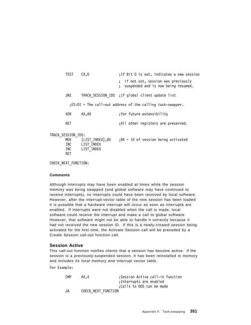
TEST CX,0 ;If Bit 0 is set, indicates a new session
; if not set, session was previously; suspended and is now being resumed.
JNZ TRACK_SESSION_IDS ;If global client update list
;ES:DI = The call-out address of the calling task-swapper.
XOR AX,AX ;for future extensibility
RET ;All other registers are preserved.
TRACK_SESSION_IDS:MOV [LIST_INDEX],BX ;BX = ID of session being activatedINC LIST_INDEXINC LIST_INDEXRET
CHECK_NEXT_FUNCTION:
Comments
Although interrupts may have been enabled at times while the sessionmemory was being swapped (and global software may have continued toreceive interrupts), no interrupts could have been received by local software.However, after the interrupt-vector table of the new session has been loadedit is possible that a hardware interrupt will occur as soon as interrupts areenabled. If interrupts were not disabled when the call is made, localsoftware could receive the interrupt and make a call to global software.However, that software might not be able to handle it correctly because ithad not received the new session ID. If this is a newly-created session beingactivated for the first time, the Activate Session call will be preceded by aCreate Session call-out function call.
Session ActiveThis call-out function notifies clients that a session has become active. If thesession is a previously-suspended session, it has been reinstalled in memoryand includes its local memory and interrupt vector table.
For Example:
CMP AX,4 ;Session Active call-in function;Interrupts are enabled;Calls to DOS can be made
JA CHECK_NEXT_FUNCTION
Appendix F. Task-swapping 351

;ES:DI = call-out address of the calling task-swapper.
TEST CX,0 ;If Bit 0 is set, indicates a new session; if not set, session was previously; suspended and is now being resumed.
JNZ TRACK_SESSION_IDS ;If global client update list
XOR AX,AX ;for future extensibility
RET ;All other registers are preserved.
TRACK_SESSION_IDS:MOV [LIST_INDEX],BX ;BX = ID of session being activatedINC LIST_INDEXINC LIST_INDEXXOR AX,AX ;for future extensibilityRET
CHECK_NEXT_FUNCTION:
Comments
If any client fails a Query Suspend or Suspend Session call-out function call,all clients may receive a call to the Session Active call-out function, includingthe client that failed the Suspend Session call. As a result clients canreceive a Session Active call without first receiving a corresponding QuerySuspend or Suspend Session call. Clients can ignore this Session Activecall.
Create SessionThis call-out function notifies clients that the task-swapper is about to createa new session.
For Example:
CMP AX,5 ;Create Session call-in function;Interrupts are enabled;Calls to DOS can be made
JA CHECK_NEXT_FUNCTION
;ES:DI = call-out address of the calling task-swapper.;BX = The session ID of the new session.
MOV AX,CREATE_SESSION_FLAGRET
352 PC DOS 7
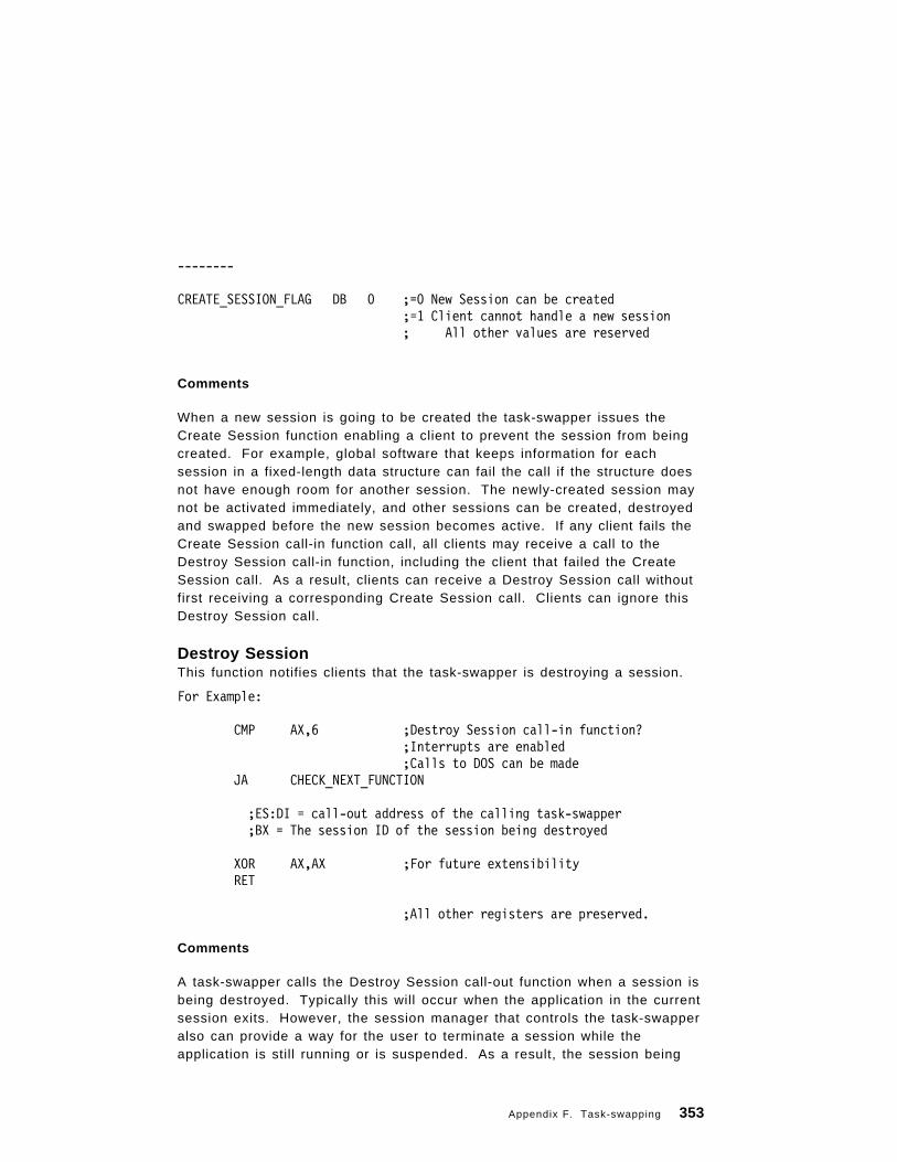
--------
CREATE_SESSION_FLAG DB 0 ;=0 New Session can be created;=1 Client cannot handle a new session; All other values are reserved
Comments
When a new session is going to be created the task-swapper issues theCreate Session function enabling a client to prevent the session from beingcreated. For example, global software that keeps information for eachsession in a fixed-length data structure can fail the call if the structure doesnot have enough room for another session. The newly-created session maynot be activated immediately, and other sessions can be created, destroyedand swapped before the new session becomes active. If any client fails theCreate Session call-in function call, all clients may receive a call to theDestroy Session call-in function, including the client that failed the CreateSession call. As a result, clients can receive a Destroy Session call withoutfirst receiving a corresponding Create Session call. Clients can ignore thisDestroy Session call.
Destroy SessionThis function notifies clients that the task-swapper is destroying a session.
For Example:
CMP AX,6 ;Destroy Session call-in function?;Interrupts are enabled;Calls to DOS can be made
JA CHECK_NEXT_FUNCTION
;ES:DI = call-out address of the calling task-swapper;BX = The session ID of the session being destroyed
XOR AX,AX ;For future extensibilityRET
;All other registers are preserved.
Comments
A task-swapper calls the Destroy Session call-out function when a session isbeing destroyed. Typically this will occur when the application in the currentsession exits. However, the session manager that controls the task-swapperalso can provide a way for the user to terminate a session while theapplication is still running or is suspended. As a result, the session being
Appendix F. Task-swapping 353

destroyed is not necessarily the current session. If any client fails the CreateSession call-in function call, all clients may receive a call to the DestroySession call-in function, including the client that failed the Create Sessioncall. As a result, clients can receive a Destroy Session call without firstreceiving a corresponding Create Session call. Clients can ignore thisDestroy Session call.
Swapper ExitThis call-in function notifies global clients that the task-swapper is no longeractive.
For Example:
CMP AX,7 ;Notification task-swapper no longer active?;Interrupts are enabled;Calls to DOS can be made
JA OUT_OF_FUNCTIONS
;ES:DI = The call-out address of the calling task-swapper.
TEST OTHER_SWAPPER_PRESENT,BX ;Other swapper present?XOR AX,AX ;AX = 0 for future extensibilityRET
OTHER_SWAPPER_PRESENT EQU 00000001B
; Bit 1 is set if no other active swappers; Bit 1 is not set if at least one task-swapper; remains after the calling task-swapper exits;All other bits are reserved and must be 0
OUT_OF_FUNCTIONS:
Comments
A task-swapper calls this function when it is no longer active as atask-swapper. This allows global software that performs extra processing todisable that processing and to coexist with the task-swapper.
This function can be called by software that invokes the actual task-swapperrather than by the task-swapper itself. For this reason the call-in addressspecified in ES:DI may differ from addresses passed with other call-outfunctions and may be NULL.
354 PC DOS 7

Appendix G. PC DOS 7 Viewer
The PC DOS Viewer that is included in PC DOS 7 is an online publicationviewer facility. It allows the user to search for, view and print information inonline books created by the IBM OS/2 Information Presentation FacilityCompiler (IPFC). The books must have an extension of .INF and be in the IPFformat. The PC DOS viewer supports a subset of the OS/2 IPF tags.
There are online books supplied with PC DOS 7, they are:
• PC DOS Command Reference (CMDREF.INF)
• REXX Information (DOSREXX.INF)
• PC DOS Error Message (DOSERROR.INF)
Invoking the ViewerThe PC DOS Viewer is invoked in one of two ways:
1. Command Line
VIEW
Launches the Viewer. A list of .INF files found in the same directoryas VIEW.EXE is displayed for the user to choose a book.
VIEW BOOKNAME
Launches the Viewer and opens the specified book at the Table ofContents.
Note: If the specified book is not in either the current directory or thesame directory VIEW.EXE is in, a path must be specified.
2. PC DOS 7.0 Tools Group in Windows
Double click on the desired book icon to launch the Viewer and open thedesired book at the Table of Contents.
Uses of Online DocumentsThe uses of online document′s are many and various. For the applicationdeveloper, the use of online documents is a boost in productivity, no longerdoes the developer need to create code to display the help text or the linksfrom subject to subject or even the string search utilities - this all becomespart of the online document structure once it has been compiled. The finalresult becomes searchable via the PC DOS viewer and allows for instant
Copyright IBM Corp. 1995 355

access from the search results to the referenced page. All of this provides amore consistent way of viewing help to the end-user.
As another example of the online document ′s use, an administrator mayprovide the user with reference manuals for their particular company - thisresults in portable and quicker access to information.
The high use of online information is very true for the OS/2 world, wheremost products shipped also have some form of online help or informationwith them - this provided via the use of the Information Presentation Facility.
Creating Online DocumentsThe information that you wish to view via the PC DOS viewer must beprepared and compiled. The Information Presentation Facility compiler issupplied with the OS/2 developers tool kit and only runs under OS/2. Foradditional information regarding the IPF compiler please refer to the OS/2Tool kit documentation. The current OS/2 IPF manual is OS/2 Warp IPFProgramming Guide, this is referenced in the preface section of this book.
To prepare your source files so that they may be recognized by the IPFcompiler, requires certain tags to be coded into the source file. Thefollowing briefly describes the process of creating a viewable onlinedocument.
The following is a simple example of using a single source file, that uses alimited number of tags, which will produce a usable online document:
:userdoc.:docprof. :title.Online Example :h1.Introduction :p.This is the introduction chapter to the rest of the document. :euserdoc.
The :userdoc. tag is always the first item in the source file. It identifies thebeginning of the IPF file. This tag is a signal to the IPF compiler to begintranslating the tagged file. The :euserdoc. is used to signal the end of thetagged document.
Place the :docprof. (document profile) tag at the beginning of your source fileafter the :userdoc. tag and before any heading definitions. Use the toc (tableof contents) attribute on the :docprof. tag to control the heading levelsdisplayed in the Content window. For example, if you want only headinglevels 1 and 2 to appear, the tagging is:
356 PC DOS 7

:docprof toc=12.
If no toc= value is specified, heading level 1 through 3 appear in theContents window.
Not to be confused with window titles, the text string specified with a :title.tag is placed into the title bar of an on-line document. When the onlinedocument is displayed, the title appears on the title line of the main window.The tagging looks like this:
:title.Endangered Mammals
The maximum length of a title string specified with a :title. tag is 47characters, including spaces and blanks.
The title tag provides a name for the online document, but is also used fortitles of Help windows. The title appears in the title bar of the main window.You usually place the title tag after the :docprof. tag.
Every file must start with a :h1. (chapter heading) tag. Heading levelsequences must not skip a level in the heading hierarchy. For example, youcannot have a heading level 1 tag (:h1.) followed by a heading level 3 tag(:h3.).
You must have at least one paragraph tag (:p.) and associated text todisplay a window. The following shows an IPF example source file:
.*:userdoc. :title.Endangered Mammals :h1 res=001.The Manatee .* :p. The manatee has a broad flat tail and two flipper like forelegs. There are no back legs. The manatee′ s large upper lip is split in two and can be used like fingers to place food into the mouth. Bristly hair protrudes from its lips, and almost buried in its hide are small eyes, with which it can barely see. .* :euserdoc.
It is a good idea to give your source file the extension of IPF, so that it maybe distinguished from other files. The IPF compiler however, will append thisextension if you do not specify a file extension when compiling. Thefollowing is the syntax that the IPF compiler will accept:
Appendix G. PC DOS 7 Viewer 357

IPFC filename [/INF] [/S] [/X] [/W] [> messageoutputfilename]
where:
filename Specifies the name of your IPF source file or base file. If you donot give a file-name extension, the IPF compiler uses .IPF bydefault. If your file has a file-name extension other than IPF,include that file-name extension in the command line.
/INF Compiles the source file as an online document. If this parameteris not included, the default is to compile the source file as a helplibrary, whose extension is .HLP.
/S Suppresses the performance of the Search function. Thisparameter increases compression of compiled data by about 10%to further reduce the storage it requires.
/X Generates and displays a cross-reference list.
/Wn Generates and displays a list of error messages. The n indicatesthe level of error messages you want to receive. Values you canspecify for n are 1, 2, or 3. For more information, see InterpretingIPFC Error Messages, that is supplied with the OS/2 tool kit.
messageoutputfilename Specifies the name of the file where error and crossreference messages are sent. If you do not specify thisparameter, messages generated by /X and /Wn are sent to thedisplay screen.
The IPF compiler is run from an OS/2 command line, as in the followingexample:
C:>IPFC MYFILE.IPF /INF
Files that may be viewed with either the PC DOS viewer or the OS/2 viewer,need to have the /INF option specified. This file is portable across bothoperating systems but, the following section describes functions and tagswhich should not be used if the online document is to be used with the PCDOS viewer.
IBM OS/2 Functions and Tags not Supported by DOSThe following major functions are not currently supported by the PC DOSViewer:
• Bookmarks
• Viewed Pages
• Libraries
358 PC DOS 7

• Graphics and hypergraphics
• Hyperlinks between books
• Launching of tutorials/applications
• Customized windows/controls
All tags and all tag options may not be supported by the PC DOS Viewer.The following table describes the tags supported by DOS and any limitations,if applicable.
Tag End Tag Exceptions (if any)
.br
.*
. im
:caution. :ecaution.
:cgraphic. :ecgraphic.
:color.
:dl. :edl.
:docprof. Only the toc= attr ibute is supported
:fig. :efig.
:figcap.
:fn. :efn.
:h1. - :h6. Only the following attributes are supported:res=, id=, name=, toc=, nosearch and h ide
:hp1. - :hp9. :ehp1. -:ehp9.
hpx, where x = 1, 2, 3, 5, 6 or 7 will result inthe string being displayed in the default font.Italicized strings will be enclosed in quotationmarks.
:i1. - :i2. Only the following attributes are supported:i d= , roo ts= , so r t key= and re f i d=
:isyn.
:li.
:link. :elink. Only the following attributes are supported:re f type= and re f type=fn
:ln
:lp
:note.
:nt. :ent.
Appendix G. PC DOS 7 Viewer 359

Again, please be aware that additional information may be found in the OS/2tool kit publications.
Tag End Tag Exceptions (if any)
:ol. :eol.
:p.
:parml. :eparml.
:pd.
:pt.
:rm.
:sl. :esl.
:table. :etable.
:title.
:ul. :eul.
:userdoc. :euserdoc.
:warning. :ewarning.
:xmp. :exmp.
360 PC DOS 7

Appendix H. Miscellaneous Control Blocks
This section identifies the structure and content of some control blocksreferenced throughout this document.
DPB - Disk Parameter Block DefinitionDPB structure:
dpb STRUCdpb_drive DB ? ; Logical drive # assoc with DPB (A=0,B=1,...)dpb_UNIT DB ? ; Driver unit number of DPBdpb_sector_size DW ? ; Size of physical sector in bytes
dpb_cluster_mask DB ? ; Sectors/cluster - 1dpb_cluster_shift DB ? ; Log2 of sectors/clusterdpb_first_FAT DW ? ; Starting record of FATsdpb_FAT_count DB ? ; Number of FATs for this drive
dpb_root_entries DW ? ; Number of directory entries dpb_first_sector DW ? ; First sector of first cluster
dpb_max_cluster DW ? ; Number of clusters on drive + 1dpb_FAT_size DW ? ; Number of records occupied by FATdpb_dir_sector DW ? ; Starting record of directorydpb_driver_addr DD ? ; Pointer to driverdpb_media DB ? ; Media byte
dpb_first_access DB ? ; This is initialized to -1 to force a media; check the first time this DPB is used
dpb_next_dpb DD ? ; Pointer to next Drive parameter blockdpb_next_free DW ? ; Cluster # of last allocated clusterdpb_free_cnt DW ? ; Count of free clusters, -1 if unknown
dpb ENDS
DPBSIZ EQU SIZE dpb ; Size of the structure in bytes
DSKSIZ = dpb_max_cluster ; Size of disk (temp used during init only)
Copyright IBM Corp. 1995 361

BPB - BIOS Parameter Block DefinitionThis structure is used to build a full DPB.
BPBLOCK STRUCBPSECSZ DW ? ; SIZE IN BYTES OF PHYSICAL SECTORBPCLUS DB ? ; SECTORS/ALLOC UNITBPRES DW ? ; NUMBER OF RESERVED SECTORSBPFTCNT DB ? ; NUMBER OF FATSBPDRCNT DW ? ; NUMBER OF DIRECTORY ENTRIESBPSCCNT DW ? ; TOTAL NUMBER OF SECTORSBPMEDIA DB ? ; MEDIA DESCRIPTOR BYTEBPFTSEC DW ? ; NUMBER OF SECTORS TAKEN UP BY ONE FAT
BPBLOCK ENDS
A_BPB STRUCBPB_BYTESPERSECTOR DW ?BPB_SECTORSPERCLUSTER DB ?BPB_RESERVEDSECTORS DW ?BPB_NUMBEROFFATS DB ?BPB_ROOTENTRIES DW ?BPB_TOTALSECTORS DW ?BPB_MEDIADESCRIPTOR DB ?BPB_SECTORSPERFAT DW ?BPB_SECTORSPERTRACK DW ?BPB_HEADS DW ?BPB_HIDDENSECTORS DW ?
DW ?BPB_BIGTOTALSECTORS DW ?
DW ?DB 6 DUP(?)
A_BPB ENDS
362 PC DOS 7

CDS - Current Directory StructureCDS items are used by the internal routines to store cluster numbers andnetwork identifiers for each logical drive. The ID field is used dually, both asnet ID and for a cluster number for local devices. In the case of localdevices, the cluster number will be -1 if there is a potential of the disk beingchanged or if the path must be recracked. The END field is the location ofthe end of the definition.
DIRSTRLEN EQU 64+3 ; Max length in bytes of directory stringsTEMPLEN EQU DIRSTRLEN*2
curdir_list STRUCcurdir_text DB DIRSTRLEN DUP (?) ; text of assignment and curdir
curdir_flags DW ? ; various flagscurdir_devptr DD ? ; local pointer to DPB or net devicecurdir_ID DW ? ; cluster of current dir (net ID)
DW ?curdir_user_word DW ?curdir_end DW ? ; end of assignmentcurdir_type DB ? ; IFS drive (2=ifs, 4=netuse)curdir_ifs_hdr DD ? ; Ptr to File System Headercurdir_fsda DB 2 DUP (?) ; File System Dependent Data Area
curdir_list ENDS
curdirLen EQU Size curdir_list ; Needed for; ASM87 which doesn′ t allow; Size directive as a macro; argument
curdir_netID EQU DWORD PTR curdir_ID
;Flag word masks curdir_isnet EQU 1000000000000000B curdir_isifs EQU 1000000000000000B ; DOS 4.0 curdir_inuse EQU 0100000000000000B curdir_splice EQU 0010000000000000B curdir_local EQU 0001000000000000B
Purpose:Maps drive letter to physical device and provide a way to keep track of eachdirectory for each drive.
Appendix H. Miscellaneous Control Blocks 363
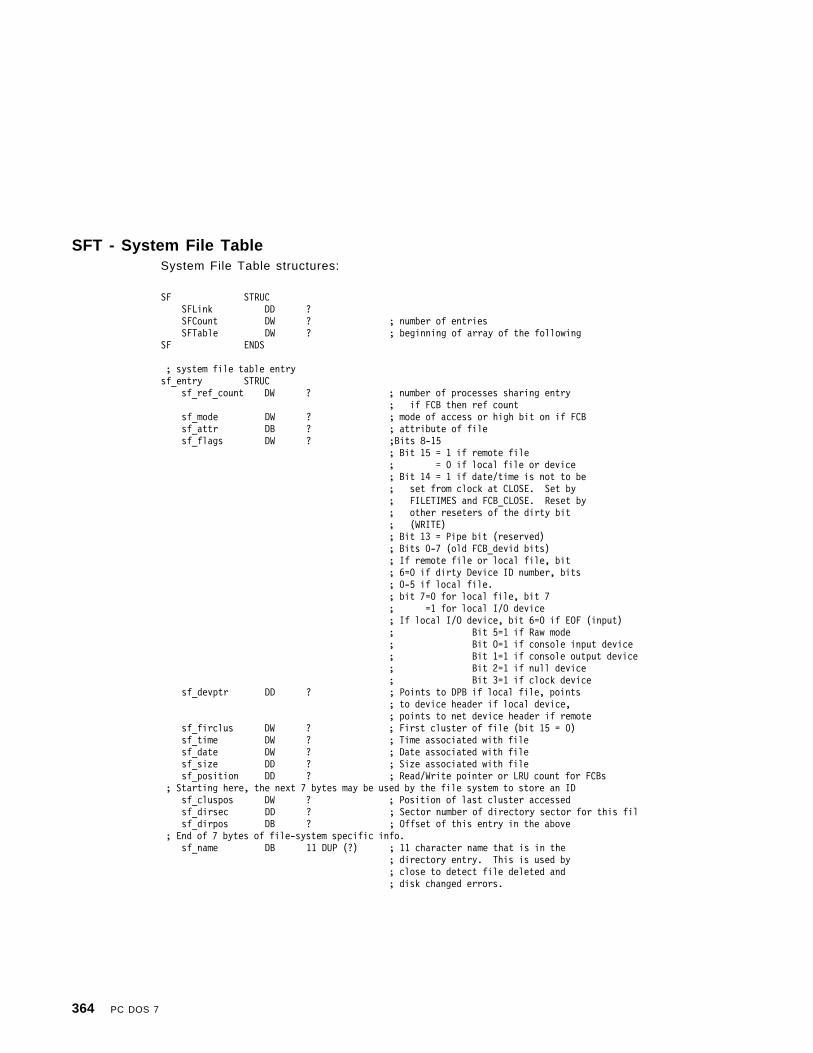
SFT - System File TableSystem File Table structures:
SF STRUCSFLink DD ?SFCount DW ? ; number of entriesSFTable DW ? ; beginning of array of the following
SF ENDS
; system file table entrysf_entry STRUC sf_ref_count DW ? ; number of processes sharing entry
; if FCB then ref countsf_mode DW ? ; mode of access or high bit on if FCBsf_attr DB ? ; attribute of filesf_flags DW ? ;Bits 8-15
; Bit 15 = 1 if remote file; = 0 if local file or device; Bit 14 = 1 if date/time is not to be; set from clock at CLOSE. Set by; FILETIMES and FCB_CLOSE. Reset by; other reseters of the dirty bit; (WRITE); Bit 13 = Pipe bit (reserved); Bits 0-7 (old FCB_devid bits); If remote file or local file, bit; 6=0 if dirty Device ID number, bits; 0-5 if local file.; bit 7=0 for local file, bit 7; =1 for local I/O device; If local I/O device, bit 6=0 if EOF (input); Bit 5=1 if Raw mode; Bit 0=1 if console input device; Bit 1=1 if console output device; Bit 2=1 if null device; Bit 3=1 if clock device
sf_devptr DD ? ; Points to DPB if local file, points; to device header if local device,; points to net device header if remote
sf_firclus DW ? ; First cluster of file (bit 15 = 0)sf_time DW ? ; Time associated with filesf_date DW ? ; Date associated with filesf_size DD ? ; Size associated with filesf_position DD ? ; Read/Write pointer or LRU count for FCBs
; Starting here, the next 7 bytes may be used by the file system to store an IDsf_cluspos DW ? ; Position of last cluster accessedsf_dirsec DD ? ; Sector number of directory sector for this filsf_dirpos DB ? ; Offset of this entry in the above
; End of 7 bytes of file-system specific info.sf_name DB 11 DUP (?) ; 11 character name that is in the
; directory entry. This is used by; close to detect file deleted and; disk changed errors.
364 PC DOS 7

; SHARING INFOsf_chain DD ? ; link to next SFsf_UID DW ?sf_PID DW ?sf_MFT DW ?sf_lstclus DW ? ; Last cluster accessedsf_IFS_HDR DD ?
sf_entry ENDSsf_fsda EQU BYTE PTR sf_cluspos ;DOS 4.0
sf_serial_ID EQU WORD PTR sf_firclus ;DOS 4.0sf_netid EQU BYTE PTR sf_cluspossf_OpenAge EQU WORD PTR sf_position+2sf_LRU EQU WORD PTR sf_positionsf_default_number EQU 5h
; Note that we need to mark an SFT as being busy for OPEN/CREATE. This is ; because an INT 24 may prevent us from ′ freeing′ it. We mark this as such ; by placing a -1 in the ref_count field.
sf_busy EQU -1 ; mode mask for FCB detection
sf_isfcb EQU 1000000000000000B ; Flag word masks
sf_isnet EQU 1000000000000000Bsf_close_nodate EQU 0100000000000000Bsf_pipe EQU 0010000000000000Bsf_no_inherit EQU 0001000000000000Bsf_net_spool EQU 0000100000000000BHandle_Fail_I24 EQU 0000000100000000B ;BIT 8 - DISK FULL I24 ERROR
; Local file/device flag masksdevid_file_clean EQU 40h ; true if file and not writtendevid_file_mask_drive EQU 3Fh ; mask for drive numberdevid_device EQU 80h ; true if a devicedevid_device_EOF EQU 40h ; true if end of file reacheddevid_device_raw EQU 20h ; true if in raw mode
devid_device_special EQU 10h ; true if special devicedevid_device_clock EQU 08h ; true if clock devicedevid_device_null EQU 04h ; true if null device
devid_device_con_out EQU 02h ; true if console outputdevid_device_con_in EQU 01h ; true if consle input
Appendix H. Miscellaneous Control Blocks 365

; structure of devid field as returned by IOCTL is:; BIT 7 6 5 4 3 2 1 0; │---│---│---│---│---│---│---│---│ ; │ I │ E │ R │ S │ I │ I │ I │ I │ ; │ S │ O │ A │ P │ S │ S │ S │ S │ ; │ D │ F │ W │ E │ C │ N │ C │ C │ ; │ E │ │ │ C │ L │ U │ O │ I │ ; │ V │ │ │ L │ K │ L │ T │ N │ ; │---│---│---│---│---│---│---│---│ ; ISDEV = 1 if this channel is a device ; = 0 if this channel is a disk file ; If ISDEV = 1 ; EOF = 0 if End Of File on input ; RAW = 1 if this device is in Raw mode ; = 0 if this device is cooked ; ISCLK = 1 if this device is the clock device ; ISNUL = 1 if this device is the null device ; ISCOT = 1 if this device is the console output ; ISCIN = 1 if this device is the console input ; If ISDEV = 0 ; EOF = 0 if channel has been written; Bits 0-5 are the block device number for ; the channel (0 = A, 1 = B, ...)
devid_ISDEV EQU 80hdevid_EOF EQU 40hdevid_RAW EQU 20hdevid_SPECIAL EQU 10Hdevid_ISCLK EQU 08hdevid_ISNUL EQU 04hdevid_ISCOT EQU 02hdevid_ISCIN EQU 01hdevid_block_dev EQU 1Fh ; mask for block device number
366 PC DOS 7

Buffer Header - Disk I/O Buffer HeaderField definition for I/O buffer information:
BUFFINFO STRUCbuf_next DW ? ; Pointer to next buffer in listbuf_prev DW ? ; Pointer to prev buffer in listbuf_ID DB ? ; Drive of buffer (bit 7 = 0)
; SFT table index (bit 7 = 1); = FFH if buffer free
buf_flags DB ? ; Bit 7 = 1 if Remote file buffer; = 0 if Local device buffer; Bit 6 = 1 if buffer dirty; Bit 5 = Reserved; Bit 4 = Search bit (bit 7 = 1); Bit 3 = 1 if buffer is DATA; Bit 2 = 1 if buffer is DIR; Bit 1 = 1 if buffer is FAT; Bit 0 = Reserved
buf_sector DD ? ; Sector number of buffer (bit 7 = 0) ; The next two items are often refed as a word (bit 7 = 0)
buf_wrtcnt DB ? ; For FAT sectors, # times sector written outbuf_wrtcntinc DW ? ; ″ ″ ″ , # sectors between each writebuf_DPB DD ? ; Pointer to drive parametersbuf_fill DW ? ; How full buffer is (bit 7 = 1)
buf_reserved DB ? ; make DWORD boundary for 386BUFFINFO ENDS
buf_offset EQU DWORD PTR buf_sector;For bit 7 = 1, this is the byte;offset of the start of the buffer in;the file pointed to by buf_ID. Thus;the buffer starts at location;buf_offset in the file and contains;buf_fill bytes.
BUFINSIZ EQU SIZE BUFFINFO; Size of structure in bytes
buf_Free EQU 0FFh ; buf_id of free buffer
;Flag byte masksbuf_isnet EQU 10000000Bbuf_dirty EQU 01000000B
;***buf_visit EQU 00100000B
;***buf_snbuf EQU 00010000B
buf_isDATA EQU 00001000Bbuf_isDIR EQU 00000100Bbuf_isFAT EQU 00000010Bbuf_type_0 EQU 11110001B ; AND sets type to ″none″
buf_NetID EQU BUFINSIZ
; ; Buffer Hash Entry Structure ;
BUFFER_HASH_ENTRY STRUC ; DOS 4.0 EMS_PAGE_NUM DW -1 ; logical page number for EMS handle
Appendix H. Miscellaneous Control Blocks 367

BUFFER_BUCKET DD ? ; pointer to buffersDIRTY_COUNT DB 0 ; number of dirty buffersBUFFER_RESERVED DB 0 ; reservedBUFFER_HASH_ENTRY ENDS
MaxBuffinBucket EQU 15 ; Max number of buffers per bucketMaxBucketinPage EQU 2 ; Max number of buckets per 16kb page
368 PC DOS 7
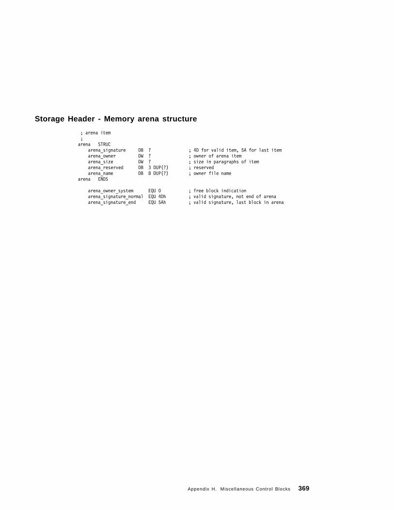
Storage Header - Memory arena structure
; arena item ;arena STRUC
arena_signature DB ? ; 4D for valid item, 5A for last itemarena_owner DW ? ; owner of arena itemarena_size DW ? ; size in paragraphs of itemarena_reserved DB 3 DUP(?) ; reservedarena_name DB 8 DUP(?) ; owner file name
arena ENDS
arena_owner_system EQU 0 ; free block indicationarena_signature_normal EQU 4Dh ; valid signature, not end of arenaarena_signature_end EQU 5Ah ; valid signature, last block in arena
Appendix H. Miscellaneous Control Blocks 369

370 PC DOS 7

Index
Special Characters/INF 358
Numerics32MB, media greater than 1128086/8088 code rules 49
Aabsolute disk read/write (INT 25H/26H) 112AC flag set condition 70Access, Lock/Unlock File 253Accessing POWER.EXE Controls 122accessing the disk 7accumulator register 136address (INT 22H), terminate 107address (INT 23H), Ctrl − Break exit 108address, default disk transfer 38address, memory map 34Address, Set Disk Transfer 168AL function values 273allocate command, EMS 79Allocate Memory 227Allocated Memory Blocks (SETBLOCK),
Modify 229Allocated Memory, Free 228Allocation Table Information 169Allocation Table Information for Specific
Device 170APM Error Return Codes 129APPEND 129application swapping 325arena structure, Memory 369ASCII in Dump command 53ASCII mode, I/O in 32ASCIIZ filename string 15Assemble command 49Assembler Language, IBM PC 136attribute field 87attribute, fi le 17
auxiliary carry flag 70Auxil iary Input 145Auxil iary Output 146
Bbase pointer 137base register 136binary mode, I/O in 32BIOS parameter block (BPB) 86, 97BIOS Parameter Block Definition 362bit fields 209Block Definition, BIOS Parameter 362Block Definition, Disk Parameter 361block device driver 85
BIOS parameter block (BPB) array 86drive letters 85input/output request 100installing a block device 86installing a character device 86media descriptor byte 86random I/O 85
Block Read, Random 179Block Write, Random 181block, parameter 39Blocks, Control 361blocks, memory 33book, organization of this 1boot record 7boot record, extended BPB 99boot sector format of BPB 98BP (base pointer) 137BPB 362BPB (see BIOS parameter block)Buffer Header 367buffer memory (disk transfer area) 26Buffered Keyboard Input 152build BPB request 97
boot sector format 98extended boot record 99extended BPB structure 98media type 98
Copyright IBM Corp. 1995 371

busy bit 91byte, media descriptor 95bytes in a request header 90bytes in directory entry 17
CCALL FAR 110calls for code page switching 282calls, using PC DOS 7 function 135Callup/Down Register Structure 323cancel all files 116cancel file 116Cancel Redirection 263carry flag 70CDS 363Change Current Directory (CHDIR) 206Change File Mode (CHMOD) 221character device driver 85
installing a new CON device 86output request 102terminating the input queue 102type-ahead input buffer 102
character input/output flush request 102character input/output status 101Check DOSDOCK Installation 118Check Standard Input Status 153check, ctrl-break 195Check, DOS Protected Mode Services 119CHECKSUM 40clear condition of flag 70Clear Keyboard Buffer and Invoke a Keyboard
Function 154clock device bit 89Close a File Handle 214CLOSE call 103Close File 158cluster number, first 20cluster, sectors per 10Code of a Subprocess (WAIT), Get a
Return 234code page switching 282Code Page, Get/Set Global 268code segment 137code, interrupt 2FH function 115codes (INT 24H). error 109
Codes, APM Error Return 129Codes, DPMS Error Return 323codes, extended error 138COM files 11COM programs 136command code 91command files from /S format option 11command l ine 40command processor 41COMMAND.COM 11, 33Commit File 270communication area 34Compare command 51compatibi l i ty mode 210computer name 256CONFIG.SYS 93Console I/O, Direct 148Console Input with Echo 143Console Input without Echo 150control block 33Control Blocks 361Control for Devices, I/O 223, 273control strings 88control values, I/O 32control-break routine 42count register 136Country Dependent Information, Get or Set 201Country Information, Get Extended 265Create a File 207Create File 165Create New File 252Create Subdirectory (MKDIR) 204Create Unique File 250Creating Online documents 356critical error handler vector (INT 24H) 108
CALL FAR 110device header format 112disk error 110error codes 109FAIL request 112hardware error 108IGNORE request 112ignore response 110IRET execution 109
crit ical error situation 42CS register 137
372 PC DOS 7

ctrl-break checking 195Ctrl-Break routine 42Ctrl − Break exit address (INT 23H) 108Current Directory Structure 363Current Directory, Get 226Current Disk 167Current Dock Status, Get 118CY flag set condition 70
Ddata area 12data files, storage of 12data register 136data segment 137Date and Time, Get/Set File′s 242date in a directory structure 20Date, Get 185Date, Set 186date, system 44DBCS vector 267, 285deallocate command, EMS 80DEBUG.COM utility 45Definition, BIOS Parameter Block 362Definition, Disk Parameter Block 361Delete a File from a Specified Directory
(UNLINK) 218Delete File 162denynone mode 212DenyRead mode 211DenyRead/Write mode 211DenyWrite mode 211descriptor byte, media 95destination index 137detect POWER.EXE 122Detecting the Expanded Memory Manager 310device driver control channel 31device driver header 87
attribute field 87clock device bit 89control strings 88definition of 87format of 87input device, standard 89IOCtl bit 88name/unit f ield 89next device header field 87
device driver header (continued)NUL device 89open/close removable media bit 88output device, standard 89pointer to interrupt routine 89pointer to strategy routine 89
device driver, EMS 301device file handle, standard 16device header format (INT 24H) 112device, local or remote 281Device, Redirect 261DeviceAttributes field 290DeviceBPB field 290Devices, I/O Control for 223, 273DeviceType field 289DI flag clear condition 70DI register 137direct access to media 112Direct Console I/O 148Direct Console Input without Echo 149direction flag 70Directory (CHDIR), Change Current 206Directory Structure, Current 363Directory, Get Current 226directory, root 11disk accessing 7disk format 7
boot record 7data area 12disk directory 11file allocation table (FAT) 10root directory 11
Disk Free Space, Get 199Disk I/O Buffer Header 367disk I/O warning 113Disk Parameter Block Definition 361Disk Reset 155Disk Transfer Address (DTA), Get 190Disk Transfer Address, Set 168disk transfer area (DTA) 26Disk, Current 167Disk, Select 156DISKCOMP utility 45Display Output 144Display String 151DN flag set condition 70
Index 373

Docking Event, Get 118done bit 91DOS Protected Mode Services Check 119DOSDOCK API 118DOSDOCK Installation, Check 118double quotation (“) 55DPB 361DPB Structure 171, 193DPMS
Allocate Block of Extended Memory 320Allocate Descriptors 316Build Alias to Real-Mode Segment 318Call Protected-Mode Procedure 314Call Real-Mode Procedure (IRET) 315Call Real-Mode Procedure (RETF) 315Call Real-Mode Procedure Interrupt
Handler 316Create Alias Descriptor 317Free a Descriptor 317Free Block of Extended Memory 320Get Descriptor Base 319Get Size of Largest Free Block of
Memory 320Installation Check 314Map Linear Memory 321Relocate Segment to Extended Memory 322Set Descriptor Base 318Set Descriptor Limit 319Set Descriptor Type/Attribute 319Unmap Linear Memory 321
DPMS Error Return Codes 323DS register 137DTA (see disk transfer area)Dump command 52Duplicate a File Handle (DUP) 224DYNALOAD 86
EEcho, Console Input with 143Echo, Console Input without 150Echo, Direct Console Input without 149EI flag set condition 70ejecting media from drive control strings 278EMM
Allocate Pages 306Deallocate Pages 308
EMM (continued)Get EMM Version 309Get Page Frame Address 304Get Status 303Get Unallocated Page Count 305Map Handle Page 307
EMM Version, Get 309EMS (see expanded memory specification)EMS-capable hardware adapter 301enable/disable device power state (1.1) 126end of status 117engage/disengage power management
(1.1) 127Enter command 55Entry, Search for First 159Entry, Search for Next 161environment string, subprogram 39error bit 91error code information 138error codes, status word 91error handler vector (INT 24H), critical 108Error Return Codes, APM 129Error Return Codes, DPMS 323Error, Extended 248ES register 137EXE extension, DEBUG 48EXE programs 38Execute a Program (EXEC), Load or 230executing a subprogram 39exit program 107Expanded Memory Manager, Detecting 310expanded memory specification (EMS) 301extended 25H or 26H 112extended BPB structure 98Extended Country Information, Get 265extended error codes 138Extended Error, Get 248extended file control block 26Extended Open/Create 271extra segment 137
FFAIL request 112failures, print 117FAR prefix, DEBUG 50
374 PC DOS 7

FAT (see file allocation table)FCB (see file control block)FCBS command 27field in parameter block 288fields in device header 87File (FIND FIRST), Find First Matching 235File (FIND NEXT), Find Next Matching 237File Access, Lock/Unlock 253file allocation table (FAT) 10file attribute 17file control block (FCB) 23
extended 26format 24logical record size 25opened file 23record number 25reserved fields 23unopened file 23
file control block structure 23File Handle (DUP), Duplicate a 224File Handle, Close a 214file handles 16file sharing using SHARE command 27File Size 175file system activities 30File Table, System 364File′s Date and Time, Get/Set 242file, cancel 116File, Close 158File, Commit 270File, Create 165File, Create New 252File, Create Unique 250File, Delete 162File, Open 157File, Open a 208File, Rename 166File, Rename a 241file, submit 116Filename, Parse 183FILES command 16files, cancel all 116files, physical location of 10Fill command 57Find First Matching File (FIND FIRST) 235Find Next Matching File (FIND NEXT) 237
first block device driver 85First Matching File (FIND FIRST), Find 235flags 136flags in register command 70flags, display 69flush function call parameter 102Force a Duplicate of a Handle (FORCDUP) 225format option, /S 11format/verify a track 293fragments, program code 136Free Allocated Memory 228function calls, using PC DOS 7 135function code, interrupt 2FH 115function dispatcher, PC DOS 7 38function request (INT 21H) 107
Ggeneral registers, list of 136generic IOCtl request 287
format/verify a track 293get device parameters 288read track on a logical device 292set device parameters 288verify a track 293write track on a logical device 292
Get a Return Code of a Subprocess (WAIT) 234Get Allocation Strategy 243Get Current Directory 226Get Current Dock Status 118Get Date 185Get Default DPB 171get device information 274get device parameters 288Get Device Power State (1.1) 125Get Disk Free Space 199Get Disk Transfer Address (DTA) 190Get Docking Event 118Get DPB 193Get Extended Country Information 265Get Extended Error 248Get InDOS Flag Address 197get installed state 116Get Interrupt Vector 198get logical device function call 104Get Machine Name 256
Index 375

get or set APM polling period 128Get or Set Country Dependent Information 201get or set idle detection strategy 123get or set POWER saving level 124get or set power status 122Get or Set System Value 195Get PC DOS 7 Version Number 191Get Printer Setup 258Get Program Segment Prefix Address 264Get PSP Address 239Get Redirection List Entry 259get statistics 127Get Time 187Get Upper-Memory Link 246Get Verify Setting 240Get/Set File′s Date and Time 242Get/Set Global Code Page 268Global Code Page, Get/Set 268Go command 58
HHandle (FORCDUP), Force a Duplicate of a 225Handle Count, Set 269handle is local or remote 281handler vector (INT 24H), critical error 108handler, installing a 132handles, file 16hard error on disk 110header, device driver 87
attribute field 87clock device bit 89control strings 88definition of 87format of 87input device, standard 89IOCtl bit 88name/unit f ield 89next device header field 87NUL device 89open/close removable media bit 88output device, standard 89pointer to interrupt routine 89pointer to strategy routine 89
HEX extension, DEBUG 48hexadecimal in Dump command 53
Hexarithmetic command 60
II/O Buffer Header, Disk 367I/O Control for Devices (IOCtl) 273
AL function values 273block device, read/write to a 277character device, read/write to a 276code page switching 282description of 273device is local or remote 280generic IOCtl request 287
format/verify a track 293get device parameters 288read track on a logical device 292set device parameters 288verify a track 293write track on a logical device 292
get device information 274handle is local or remote 281input device status 278lock conflicts 281logical drive check 296media lock or unlock, and eject 278output device status 278query device 298query handle 298removable media determination 279set device information 274set logical drive 297sharing and lock conflict retries 281
IBM PC Assembler Language 136IBMBIO.COM 11IBMDOS.COM 11ignore response 110index register 137INF 355initialization request 93initializing a device driver 86input bit, standard 89Input command 61Input Status, Check Standard 153Input, Auxiliary 145input/output request 100installed state, get 116
376 PC DOS 7

install ing device drivers 85installing the handler 132instruction pointer 137INT21 function call 135internal stack 137interrupt 21H, issuing 135Interrupt 2FH Function AH=54H POWER.EXE
control 120interrupt 2FH function AX-530BH PM event
broadcast 120interrupt 2FH function AX-530CH PM event first
phase broadcast 122interrupt f lag 70interrupt routines 90
build BPB request 97character input/output flush request 102character input/output status requests 101command code value 92generic IOCtl request 104get logical device request 104initialization request 93input/output request 100IOCtl query 105media check request 94media descriptor byte 95nondestructive input request 101open or close request 102removable media request 103request data structures 92request header 90set logical device request 105
Interrupt Vector, Get 198Interrupt Vector, Set 177invalid responses 111IOCtl (see I/O Control for Devices)IOCtl bit 88IOCtl query 105IOCtl request, generic 104IP (instruction pointer) 137IPF 355IPF compiler 356IPFC 355IRET (return-from-interrupt instruction) 108
KKeyboard Buffer and Invoke a Keyboard
Function, Clear 154Keyboard Input, Buffered 152
LLAN (see local area network)LIM (see Lotus/Intel/Microsoft)LIM specification 301List Entry, Get Redirection 259Load command 61Load or Execute a Program (EXEC) 230load time, identify program at 36loading a subprogram 39loading an overlay 41loading data using DEBUG 62local area network (LAN) 21local device, handle is 281local or remote device 280location of files on disk 10lock conflicts 281Lock/Unlock File Access 253locking media drive control strings 278logical device function call, get/set 104logical drive check 296logical record size 25logical sector numbers (LSN) 113Lotus/Intel/Microsoft (LIM) 301LSN (see logical sector numbers)
MMachine Name, Get 256map command, EMS 80media >32MB 112media determination, removable 279media warning, removable 114MediaType field 290Memory arena structure 369memory blocks 33Memory Blocks (SETBLOCK), Modify
Allocated 229memory buffer (disk transfer area) 26memory map address 34
communication area 34
Index 377
memory supported by PC DOS 7 301Memory, Allocate 227Memory, Free Allocated 228Mode (CHMOD), Change File 221Modify Allocated Memory Blocks
(SETBLOCK) 229Move command 64Move File Read Write Pointer (LSEEK) 219multiplex (INT 2FH) 115
APPEND 129install a handler 132interrupt 2FH function code 115print error codes 116
NNA flag clear condition 70name a file 15Name command 65Name, Get Machine 256name/unit f ield 89NAME=parameter 39National Language Support (NLS) 21NC flag set condition 70NEAR prefix, DEBUG 50network path 21network redirection 260NewName string 241next device header 87Next Entry, Search for 161Next Matching File (FIND NEXT), Find 237NG flag set condition 70NLS (see National Language Support)NLSFUNC DOS extension 266nondestructive input request 101NUL device 89numbering convention, register 137NumberOfCylinders field 290NV flag clear condition 70NZ flag clear condition 70
OOpen a File 208Open a File, matrix of 213OPEN call 103
Open File 157open mode 209Open/Create, Extended 271opened file control block 23OS/2 Toolkit 356output bit, standard 89Output command 66Output, Auxiliary 146Output, Display 144Output, Printer 147output/input request 100OV flag set condition 70overflow flag 70overlay, loading an 41
Pparagraphs of memory 33Parameter Block Definition, BIOS 362Parameter Block Definition, Disk 361parameter block to subprogram 39parameter block, field in 288parity flag 70Parse Filename 183parsing 27path, network 21PC DOS 7 format command 7PC DOS 7 function dispatcher 38PC DOS 7 organization of book 1PC DOS 7 registers, see registers, PC DOS 7PC DOS 7 system files 11PC DOS 7 Version Number, Get 191PC DOS 7 Viewer 355PC DOS 7, hardware required 5PE flag set condition 70physical location of files 10PL flag clear condition 70PM event broadcast, interrupt 2FH function
AX-530BH 120PM event first phase broadcast, interrupt 2FH
function AX-530CH 122PO flag clear condition 70pointer to next device header field 87pointer to strategy/interrupt routines 89pointers, list of 137POWER.EXE control, Interrupt 2FH Function
A H = 5 4 H 120
378 PC DOS 7

Prefix Address, Get Program Segment 264prefix structure, program segment 36print error codes 116print failures 117print, resident part of 115Printer Output 147Printer Setup, Get 258Printer Setup, Set 257Proceed command 67Process (EXIT), Terminate a 233processor, calling a command 41Program (EXEC), Load or Execute a 230program (INT 20H), terminate 107program code fragments 136program remain resident 114program segment 36program segment prefix 38Program Segment Prefix Address, Get 264program segment prefix structure 36Program Segment, Create New 178Program Terminate 142
QQuit command 68
RRandom Block Read 179Random Block Write 181Random Read 172Random Write 173re-displaying Load command 62Read from a File or Device 215read track on a logical device 292Read Write Pointer (LSEEK), Move 219Read, Random 172Read, Random Block 179Read, Sequential 163read/write (INT 25H/26H), absolute disk 112Record Field, Set Relative 176record number 25Redirect Device 261Redirection List Entry, Get 259Redirection, Cancel 263redirection, network 260
reduce allocated memory 33Register command 68
changing a flag 70list of flag settings 70
Register Structure, Callup/Down 323registers, display 69remain resident, program 114remote device, handle is 281remote or local device 280removable media determination 279removable media warning 114Remove Subdirectory (RMDIR) 205Rename a File 241Rename File 166reopen a file (matrix) 213request header 90
busy bit 91command code field 91done bit 91error codes, status word 91status field 91unit code field 91
reserved fields in file control block 23Reset, Disk 155resident (INT 27H), terminate but stay 114resident part of print 115responding to errors 138response, ignore 110responses, invalid 111Return Code of a Subprocess (WAIT), Get 234Return Codes, APM Error 129Return Codes, DPMS Error 323return from interrupt (IRET) 43return-from-interrupt instruction (IRET) 108ROM BIOS routine 145ROM communication area 34root directory 11routines, pointer to strategy/interrupt 89
SS format option 11save area, parameter 38save mode of device driver 90Search command 71Search for First Entry 159
Index 379

Search for Next Entry 161search in disk directory 26sector sequence on formatted disk 7sector size 7Segment Prefix Address, Get Program 264segment prefix, program 38segment register 137Segment, Create New Program 178Select Disk 156separators, fi lename 183Sequential Read 163Sequential Write 164Services Check, DOS Protected Mode 119Set Allocation Strategy 245set condition of flag 70Set Date 186set device information 274set device parameters 288set device power state (1.1) 125Set Disk Transfer Address 168Set Extended Error 255Set Handle Count 269set logical device function call 105set logical drive 297Set Printer Setup 257Set PSP Address 238Set Relative Record Field 176Set Time 188Set Upper-Memory Link 247Set/Reset Verify Switch 189Setting, Get Verify 240SFT 364sharing and lock conflicts 281sharing mode 209SI register 137sign flag 70single block device driver 85single quotation (‘) 55Size, File 175size, logical record 25source index 137SP (stack pointer) 137SP register 38SpecialFunctions field 288SS register 137stack, internal 137
stack, user 109standard device file handle 16standard input bit 89standard output bit 89starting a device driver 86starting DEBUG 45static environment 38status 117status command, EMS 81status field 91status function call parameter 101status word error codes 91status, end of 117Status, Get Current Dock 118STDAUX 16STDERR 16STDIN 16STDOUT 16STDPRN 16Storage Header 369String, Display 151string, NewName 241 string, subprogram environment 39Structure, Current Directory 363structure, Memory arena 369structure, program segment prefix 36subdirectories, location of 12Subdirectory (MKDIR), Create 204Subdirectory (RMDIR), Remove 205subdirectory entries 17subfunction calls for code page switching 282submit fi le 116Subprocess (WAIT), Get a Return Code of
a 234support of expanded memory 301swapping, application 325swapping, task 325Switch, Set/Reset Verify 189system date and time 44System File Table 364System Value, Get or Set 195
TTable, System File 364task-swapping 325
activate session 350
380 PC DOS 7

task-swapping (continued)API info struc data structure 331build call-out chain 336client initialization 327client int 2FH handler 327client int 2FH handler functions 335client termination 330client, the term 326create session 352destroy session 353detect swapper (function 4B02H) 335Function Descriptions 334get version 340hook call-out 342identify instance data 338init swapper 346instance item struc data structure 333mainframe communications software 325pending creation of a new session 329pending session switch 328protocol 326query API support 344query suspend 347session active 351suspend session 349swapper exit 354swapper ver structure 333switch call back info data structure 330task-swapper call-in functions 339, 345task-swapper Int 2FH handler functions 335test memory region 341TSR programs 325unhook call-out 343Win386 startup info struc data structure 332with Windows 326
terminate (INT 20H), program 107Terminate a Process (EXIT) 233terminate address (INT 22H) 107terminate but stay resident (INT 27H) 114Terminate Process and Remain Resident 192Terminate, Program 142terminating the input queue 102terminators, f i lename 183time in a directory structure 19Time, Get 187Time, Get/Set File′s Date and 242
Time, Set 188time, system 44Toolkit, OS/2 356Trace command 72track, format/verify a 293TrackLayout field 291Transfer Address, Set Disk 168transfer area, disk 26
UUMB support 94Unassemble command 74unit code field 91unit field 89unlocking media drive control strings 278unopened file control block 23UP flag clear condition 70user stack 109using PC DOS 7 function calls 135utility, DEBUG.COM 45utility, DISKCOMP 45
Vvalues in a command code 91vector (INT 24H), critical error handler 108vector table 34Vector, Get Interrupt 198Vector, Set Interrupt 177vectors, requesting and specifying the
interrupt 44verify a track 293Verify Setting, Get 240Verify Switch, Set/Reset 189
Wword fields in device header 87wraparound 100Write command 76Write to a File or Device 216write track on a logical device 292Write, Random 173Write, Random Block 181Write, Sequential 164
Index 381

Zzero flag 70ZR flag set condition 70
382 PC DOS 7


IBML
Printed in U.S.A.
GG24-4459-00