Embed Size (px)
Citation preview
User’s Manual
DOS-Controller 2C
COE DT / 1.1/ 20.06.2006
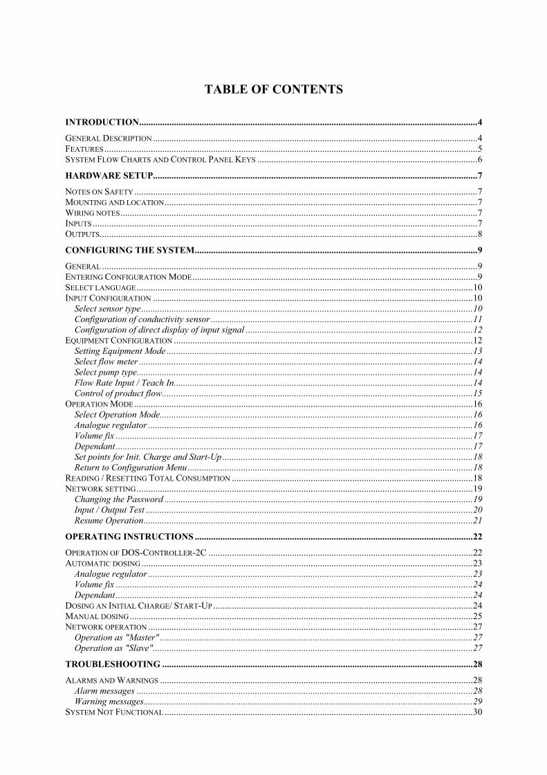
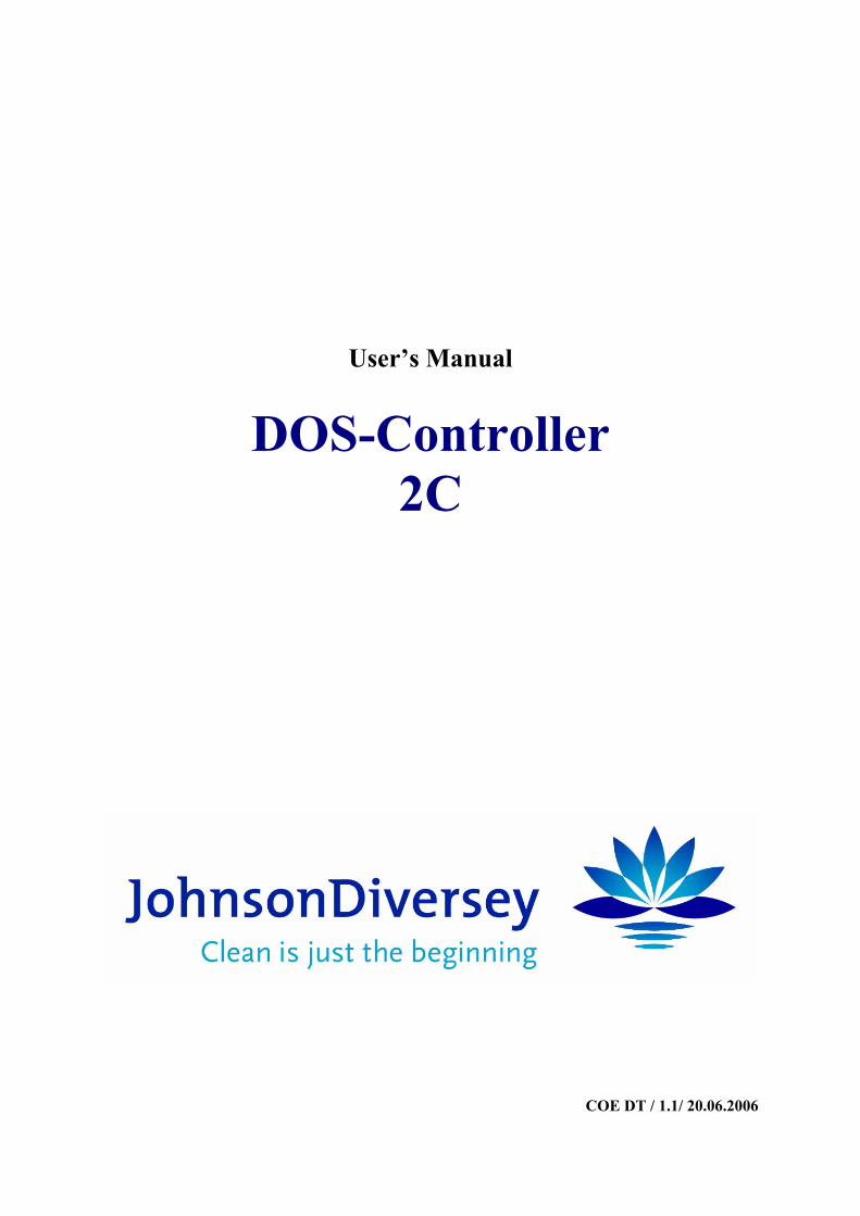
TABLE OF CONTENTS
INTRODUCTION..................................................................................................................................................4
GENERAL DESCRIPTION ............................................................................................................................................4 FEATURES.................................................................................................................................................................5 SYSTEM FLOW CHARTS AND CONTROL PANEL KEYS ...............................................................................................6
HARDWARE SETUP............................................................................................................................................7
NOTES ON SAFETY ....................................................................................................................................................7 MOUNTING AND LOCATION.......................................................................................................................................7 WIRING NOTES..........................................................................................................................................................7 INPUTS ......................................................................................................................................................................7 OUTPUTS...................................................................................................................................................................8
CONFIGURING THE SYSTEM..........................................................................................................................9
GENERAL ..................................................................................................................................................................9 ENTERING CONFIGURATION MODE...........................................................................................................................9 SELECT LANGUAGE.................................................................................................................................................10 INPUT CONFIGURATION ..........................................................................................................................................10
Select sensor type ...............................................................................................................................................10 Configuration of conductivity sensor .................................................................................................................11 Configuration of direct display of input signal ..................................................................................................12
EQUIPMENT CONFIGURATION .................................................................................................................................12 Setting Equipment Mode ....................................................................................................................................13 Select flow meter ................................................................................................................................................14 Select pump type.................................................................................................................................................14 Flow Rate Input / Teach In.................................................................................................................................14 Control of product flow......................................................................................................................................15
OPERATION MODE ..................................................................................................................................................16 Select Operation Mode.......................................................................................................................................16 Analogue regulator ............................................................................................................................................16 Volume fix ..........................................................................................................................................................17 Dependant ..........................................................................................................................................................17 Set points for Init. Charge and Start-Up ............................................................................................................18 Return to Configuration Menu ...........................................................................................................................18
READING / RESETTING TOTAL CONSUMPTION ........................................................................................................18 NETWORK SETTING.................................................................................................................................................19
Changing the Password .....................................................................................................................................19 Input / Output Test .............................................................................................................................................20 Resume Operation..............................................................................................................................................21
OPERATING INSTRUCTIONS ........................................................................................................................22
OPERATION OF DOS-CONTROLLER-2C ..................................................................................................................22 AUTOMATIC DOSING ...............................................................................................................................................23
Analogue regulator ............................................................................................................................................23 Volume fix ..........................................................................................................................................................24 Dependant ..........................................................................................................................................................24
DOSING AN INITIAL CHARGE/ START-UP ................................................................................................................24 MANUAL DOSING ....................................................................................................................................................25 NETWORK OPERATION ............................................................................................................................................27
Operation as "Master" .......................................................................................................................................27 Operation as "Slave"..........................................................................................................................................27
TROUBLESHOOTING ......................................................................................................................................28
ALARMS AND WARNINGS .......................................................................................................................................28 Alarm messages .................................................................................................................................................28 Warning messages..............................................................................................................................................29
SYSTEM NOT FUNCTIONAL .....................................................................................................................................30
TABLE OF CONTENTS
Page 3
JohnsonDiversey DOS-Controller 2C
EXAMPLE............................................................................................................................................................31
SYSTEM-CONFIGURATIONEN IN STAND-ALONE-MODE ............................................................................................31 SYSTEM-CONFIGURATIONEN IN MASTER-SLAVE-MODE.........................................................................................32 APPENDIX A: SPECIFICATIONS................................................................................................................................35 APPENDIX B: ELECTRICAL CONNECTIONS ..............................................................................................................36 APPENDIX C: MENU SCHEMES................................................................................................................................40
Operation Menu .................................................................................................................................................40 Configuration Menu...........................................................................................................................................41 Input Configuration, Submenu to Configuration ...............................................................................................42 Equipment Configuration (stand alone mode) ...................................................................................................43 Equipment Configuration (Master)....................................................................................................................44 Equipment Configuration (Slave) ......................................................................................................................45
APPENDIX D: PARAMETER LIST..............................................................................................................................46 APPENDIX E: MOUNTING DIAGRAM .......................................................................................................................50 APPENDIX F: SPECIFIC CONDUCTIVITY DIAGRAMS..................................................................................................51
GLOSSARY..........................................................................................................................................................52
Introduction
Page 4
Introduction
General Description The DOS-Controller-2C is part of an innovative modular system solution for the dosing of cleaning products for bottle-washing machines. It offers a high level of flexibility:
• The concentration of product can be controlled via dosing of fixed volume per time or by measuring and controlling the conductivity of the cleaning fluid.
• An additive can be added either as fixed volume per time or proportional to the volume of the main product.
• One DOS-Controller-2C is controlling two different parts of a bottle washer.
• Two DOS-Controller-2Cs can be coupled together using the same equipment’s controlling three different parts of a bottle washer.
The system consists of a DOS-Controller-2C unit and one dosing pump per product. Additional inputs are necessary for operation. To improve operation additional flow sensors can be added to control consumption. If necessary, level sensors can be added to check the level of product.
A second DOS-Controller-2C may be coupled together using the same equipment and controlling different stages of a machine. In this case one DOS-Controller-2C is "Master" and controls all dosing equipment and one part of the machine. The other DOS-Controller-2C acts as a slave, and controls valves from the transport line, to the second and third part of the machine. DOS-Controller-2Cs communicate via CAN-Bus.
* * *
When a system with a single DOS-Controller-2C is running in Automatic Mode, the DOS-Controller-2C works automatically stand-alone. A system, composed of two DOS-Controller-2C's running in Automatic Mode, requires CAN-Bus -Interfaces. In this case the "Slave"-Controls requests a product type and wait for a response by its "Master".
The possible activities of a DOS-Controller-2C are as follows: No Release : no dosing activity possible Automatic : Dosing automatically Initial Charge : Dosing an initial charge start-up : Dosing a start-up charge Manual : Dosing a manually set charge of product
* * *
The DOS-Controller-2C system is comprised of a wall mountable control unit with a separate access area for the port connections. The control panel has 4 keys and a LCD display with 2 x 16 digits. All activities of the dosage system are regulated from the control panel, and from the attached external devices. The control system is configured using the commands and input screens on the LCD display. Four relay outputs control the four dosing equipment’s (dosing pumps or valves). For each dosing item, there is one ‘power’ digital output driving the pump or, in "Slave"-Mode the valves. Four additional opto-coupler outputs control the stroke pulses if stroked dosing pumps are used. DOS-Controller-2C systems can be activated/ inhibited by external devices through one trigger release. "Initial Charge" and "Start-Up"-dosing can be started by external devices through separate trigger inputs. Optionally, systems can be networked to a computer running a configuration and monitoring software through a CAN-Bus interface.
JohnsonDiversey DOS-Controller 2C
Introduction
Page 5
Features • Controls dosing processes for product and additive in two baths
• Monitors daily and total consumption for each cleaning product and bath.
• Triggers alarm messages and halts current processing step when physical alarms occur.
• Systems can be networked through an optional CAN-Bus interface.
• Password protection.
• Different operating modes for dosing pump
• Different operating modes for concentration control
Example for a DOS-Controller-2C network with the maximum of 1 master and 1 Slave. In this example the master controls bath 1 and the dosing pumps. Slave 1 controls bath 2 and bath 3 . An activated valve opens the way to the bath. Every controller gets a trigger signal from his bath to start the dosing process. Every bath is be controlled by an analogue regulator. The level control indicators must be connected to the Master control only.
JohnsonDiversey DOS-Controller 2C
Introduction
Page 6
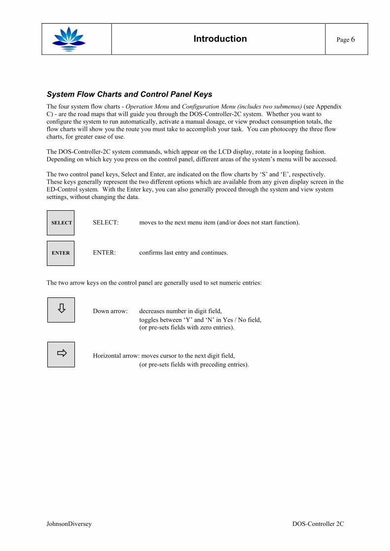
System Flow Charts and Control Panel Keys The four system flow charts - Operation Menu and Configuration Menu (includes two submenus) (see Appendix C) - are the road maps that will guide you through the DOS-Controller-2C system. Whether you want to configure the system to run automatically, activate a manual dosage, or view product consumption totals, the flow charts will show you the route you must take to accomplish your task. You can photocopy the three flow charts, for greater ease of use. The DOS-Controller-2C system commands, which appear on the LCD display, rotate in a looping fashion. Depending on which key you press on the control panel, different areas of the system’s menu will be accessed. The two control panel keys, Select and Enter, are indicated on the flow charts by ‘S’ and ‘E’, respectively. These keys generally represent the two different options which are available from any given display screen in the ED-Control system. With the Enter key, you can also generally proceed through the system and view system settings, without changing the data. SELECT SELECT: moves to the next menu item (and/or does not start function). ENTER ENTER: confirms last entry and continues. The two arrow keys on the control panel are generally used to set numeric entries:
Down arrow: decreases number in digit field, toggles between ‘Y’ and ‘N’ in Yes / No field, (or pre-sets fields with zero entries).
Horizontal arrow: moves cursor to the next digit field, (or pre-sets fields with preceding entries).
JohnsonDiversey DOS-Controller 2C
Hardware Setup
Page 7
Hardware Setup
Notes on Safety To ensure that the controller functions perfectly and has a long, useful life, the user must observe the instructions in this manual and must proceed according to the conditions of use. Commissioning and maintenance personnel must have been trained and authorized to carry out such activities. Appropriate measures must be taken to prevent unintended actuation and resulting detrimental influences on the process. The applicable prevention and safety regulations for electrical devices must be observed during operation, maintenance and repair of the controller. All electrical connections must be made by a qualified electrician. Always disconnect from power supply before opening cover. Danger of electrical shock inside. Electrical components should not be exposed to water or moisture. If this occurs by accident, the unit must be serviced by a qualified electrician.
Mounting and location The DOS-Controller-2C unit should be mounted on a clean, vertical surface and kept away from heat (<50°C), moisture and vibrations. As shown in the mounting diagram (Appendix E), there are six mounting holes to mount the DOS-Controller-2C unit to a wall - three on each side on the back wall of the plastic box. When you have located the place for the control unit, mount the box securely in place. The flow sensors must be installed in a straight length of pipe, with a minimum of ten diameters of straight pipe before and five diameters of straight pipe after the sensor to ensure correct operation.
Wiring notes For the electrical wiring of the components, pay attention to the maximum cable lengths between the ED-Control unit and the other components (refer to the technical manuals of the components). Connect wiring as shown in wiring diagram (Appendix B). Connect power to the port labeled N, PE, L1. Make sure that all attached equipment is in conformance with the electrical specifications (Appendix A).
Inputs Release Trigger. The Release Trigger can be connected to a switch or to an external device, for remote triggering of the system. The system will only run when the external contact is closed or when the Release Trigger signal is set to ‘low’. Initial Charge/ Start-Up. These inputs can be connected to a switch or to an external device, for remote start of an initial charge (or start-up) dosing. The system will start when the external contact is closed or when this input signal is set to ‘low’. Flow Sensor: The flow sensors are optional and can be disabled during configuration. In this case no control over consumption of product is possible, product flow will be calculated from the characteristics of the dosing pump. The product consumption can be calculated too.
JohnsonDiversey DOS-Controller 2C
Hardware Setup
Page 8
Level alarm: Connect level switches for the empty level. All input clamps also feature 0 volt and 24 volt access. A ‘high' signal (open contact) refers to an empty tank; a ‘low' signal (closed contact) refers to a tank which is not empty. A broken wire or a faulty connection will also prompt an alarm. This contact is closed if product is running empty, an immediate alarm will be produced.
Outputs Connect the pumps to the respective output ports. If you are using a Stroke pump, connect the pump also to the corresponding Stroke output port. The system provides two relay outputs as alarm and running signal. The Alarm output can be used to trigger an external alarm, by attaching it to a lamp or a horn. The Running output signifies normal operation, and can be attached to an external device. For the maximum output ratings, see the Specifications sheet (Appendix B) .
JohnsonDiversey DOS-Controller 2C
Configuring the System
Page 9
Configuring the System
General The DOS-Controller-2C system automatically controls the concentration of Product and feeds the necessary product into the machinery. To accomplish this, the DOS-Controller-2C controls 2 sensors and 4 pumps.
Sensor: Sensor 1 : measures the product concentration in bath 1 Sensor 2 : measures the product concentration in bath 2 Pumps: Equip. 1 : pumps main product to bath 1 Equip. 2 : pumps additive to bath 1 Equip. 3 : pumps main product to bath 2 Equip. 4 : pumps additive to bath 2
Equipment 1/3 can be configured to perform a time constant dosing ("Volume Fix") or to control the concentration of product. When the system is running in Automatic Mode, dosing will be performed automatically until the Trigger Release input is set to ‘low’. When inappropriate values are entered in the Configuration Menu, or a setting is not possible, the DOS-Controller-2C system will inform the user. While the system is being configured, the DOS-Controller-2C system will not perform any dosages - all of the system outputs are blocked and set to ‘low’. When the Configuration Menu is exited, the system is immediately ready to perform dosages. The system is configured using the four control keys on the control unit and the commands on the LCD display. It is necessary to use the system’s flow charts - Operation Menu and Configuration Menu (including two submenus) - in order to configure the system (see System Flow Charts and Control Panel Keys, page 7).
Entering Configuration Mode When the control unit is turned on for the first time, the start-up screen will read:
Configuration Enter
As shown on the Operation Menu flow chart (bottom left corner), press the Enter key to confirm, and begin Configuration.
Enter Password xxxx
The system requires that you enter a password in order to have access to configuration capabilities. Enter your four-digit password, using the down arrow key and the horizontal arrow key. Press the Enter key again, and you will be in the Configuration Menu - see the Configuration Menu flow chart. The general set-up of the control system will now be configured., product consumption totals can be read and reset here, the password may be changed, and the inputs and outputs can be tested. Referring to the Configuration Menu flow chart (Appendix A), use the keys on the control panel to respond to the information on the LCD display (see System Flow Charts and Control Panel Keys).
JohnsonDiversey DOS-Controller 2C
Configuring the System
Page 10
Select language The language of the user interface can be selected to suit the personal needs of the user/ operator.
Language Setting Enter
If this menu item is selected, a choice of four languages is presented
Sel. Language (E/D/F/Sp/P): E
The following languages are integrated and can be selected:
English (E) German (D) French (F) Spanish (Sp) Portugese (P)
After selection of the language, the actual type and version of the software is displayed.
DOS-Controller-2C Version 1.0
Input Configuration The first screen in the Configuration Mode is:
Sensor Config. Enter
As shown in the Control Configuration flow chart, press the Enter key, to confirm and proceed to Input Configuration. Input Configuration Flow Chart All of the parameters which define the specific operation of both inputs (sensors) will now be configured. Referring to the Input Configuration flow chart (Appendix C), use the keys on the control panel to respond to the information on the LCD display (see System Flow Charts and Control Panel Keys).
Select sensor type
Select sensor 1: Conduct.
The sensor input can be connected to different types of sensors. Press the down arrow key, to toggle between the following choices:
Conductivity : Conductivity sensor, different options for displayed unit and range as well as internal or external temperature compensation can be configured
direct : The direct display of the input current can be in "mA" or in "%" of full scale.
JohnsonDiversey DOS-Controller 2C
Configuring the System
Page 11
Sel. Current Min 1: (0/4mA): 4
In any case the minimum current of the sensor has to set. A selection of 0 A or 4 mA is possible depending whether a "live zero" (4-20mA) is used or not (0-20mA)
Configuration of conductivity sensor Every step in configuration can be left by pressing the SELECT-key. In this case DOS-Controller-2C switches back to the screen "Select sensor / 1: ...".
Cond. Sel. Unit 1: mS
The conductivity sensor input signal (analogue input 1) can be displayed in various ways. The direct display in "mS" or "µS" is possible as well as an indirect display in terms of concentration of a product. to different types of sensors. Press the down arrow key, to toggle between the following choices:
mS / µS : Conductivity displayed in physical units, either mS or µS. The maximum scale has to be set also ("Cond. Scale max.", see below).
NaOH : The concentration of NaOH is displayed. The measured conductivity is transformed into a concentration value via a stored calculation diagram. The maximum scale has to be set also.
KOH : The concentration of KOH is displayed. The measured conductivity is transformed into a concentration value via a stored calculation diagram. The maximum scale has to be set also
H3PO4 : The concentration of H3PO4 (Phosphorous acid) is displayed. The measured conductivity is transformed into a concentration value via a stored calculation diagram. The maximum scale has to be set also
H2SO4 : The concentration of H2SO4 (Sulphuric acid) is displayed. The measured conductivity is transformed into a concentration value via a stored calculation diagram. The maximum scale has to be set also
HNO3 : The concentration of HNO3 (Salpetric acid) is displayed. The measured conductivity is transformed into a concentration value via a stored calculation diagram. The maximum scale has to be set also
free : A free concentration is displayed. The measured conductivity is transformed into a concentration value via a stored calculation diagram, this diagram is set by the user ("Free Cond. Curve", see below).
Cond. Scale max. 1: 2000 mS
The maximum scale of the sensor (analogue input 1) is set in a range from 1 to 2000 µS / mS. This is the conductivity necessary to produce 20mA output current by the sensor.
Cond. Free Curve 1-1:0500mS=00,0%
Cond. Free Curve 1-1:0500mS=07,5%
If the conductivity has to be displayed in terms of a user specific characteristic, data of a concentration characteristic can be set. For up to 8 points of a characteristic (called 1-1...1-8) the conductivity in µS / mS and the corresponding
JohnsonDiversey DOS-Controller 2C
Configuring the System
Page 12
concentration have to be set. If a conductivity value has been set to the desired value the ENTER-key has to be pressed to switch to concentration. If a concentration value has been set to the desired value the ENTER-key has to be pressed to switch to the conductivity of the next point. The relationship between concentration and conductivity has to be a monotonous rising function. Therefore the default values for the first point are "0 µS / mS" and "0%". Setting the following points the minimum values for both concentration and conductivity will be the corresponding value of the previous point. The default values for these points are the values of the previous point. That is, if an additional data point for a characteristic has to be entered, some points will have to be shifted. It is possible to see all the data points by pressing ENTER multiple times.
Configuration of direct display of input signal This step in configuration can be left by pressing the SELECT-key. In this case DOS-Controller-2C switches back to the screen "Select sensor / 1: ...".
Direct Display 1: (mA/%) mA
If the input current has to be displayed directly, the option "mA" has to be selected. of sensors. Press the down arrow key, to toggle between the following choices:
mA : Input current will be displayed in mA with a resolution of 0,02 mA. The maximum scale is 20mA.
% : Input current will be displayed as % of full scale with a resolution of 0,1 %. Full scale may be 0-20mA or 4-20mA depending on "Current min."-setting. A current of 8 mA will be displayed as 40,0% (4-20mA) or 25,0% (0-20mA)
Equipment Configuration The second screen in the Configuration Mode is:
Equipment Config Enter
Equipment Configuration Flow Chart All of the parameters which define the specific operation of the equipment (dosing pumps) will now be configured. Referring to the Equipment Configuration flow chart (Appendix A), use the keys on the control panel to respond to the information on the LCD display (see System Flow Charts and Control Panel Keys). The first screen in Equipment Configuration is:
Equipm. : 1 2 3 4 Mode: R D R F
This screen displays the current configuration of each of the four pump outputs. The different operation modes of the dosing pumps have the following abbreviations:
R analogue Regulator (Equipment 1,3) F volume Fix (Equipment 1-4) D Dependant (Equipment 2,4 only) 0 Off (Equipment 1-4)
JohnsonDiversey DOS-Controller 2C
Configuring the System
Page 13
Before the system has been configured for the first time, all pump configurations will be set to ‘0’. Press the Select key to proceed to the next screen.
Select Equipment (1-4): 1
The cursor will be located in the digit field on the LCD display. Press the down arrow key, until ‘1’ appears in the digit field, to program the first piece of equipment (pump). Press the Enter key to proceed.
Setting Equipment Mode
Equipment Mode 1: (P/V/O) = I
Every piece of equipment may be activated or deactivated. The operation mode of each individual piece of equipment (pump or valve) has to be set according to the system set-up. Details of the operating mode will be configured later. Rotate between the three choices, using the Select key. If you do not want to use a pump, you may disable it by selecting ‘O’. When a pump is disabled, a ‘0’ will occupy that pump’s corresponding position in the ‘Equ. Mode’ display. Depending on operation mode, the equipment may be set as "Valve". See application scheme and the chapter on "Network operation" for details on the necessary set-up. When you have made your choice, press the Enter key to confirm this screen. Note: If a network of a Master and a Slave is to be configured, care must be taken during configuration of the
master: All the equipment that is used by the network has to be configured at the Master, even if not used by the Master. Only the Master has information about pump type and flow meter data. If any equipment is not used by the Master but used by the Slave, act as follows: Set equipment to be on, define its data as necessary and to disable it at the Master set the "Operation Mode = Volume Fix (F)" and "Fixed Volume = 0,0 kg" or "Interval Time = 0 sec. With these settings, the equipment is defined completely but is not dosing at the Master Control himself.
JohnsonDiversey DOS-Controller 2C
Configuring the System
Page 14
Select flow meter
Prod. Flow meter 1: (Y/N) = Y
An additional flow meter may be activated or deactivated. The operation mode of each piece of individual equipment will be configured later. Rotate between the two choices, using the Select key.
Select pump type
Select Pump Type 1: (S/P) : S
For all equipment (pump 1-4) the pump type can be selected between "Permanent" and "Stroke". When you have made your choice, press the Enter key to confirm this screen. If the pump type is selected to be "Stroke", two additional times have to be set:
Stroke Time 1: 9,9 sec
"Stroke time" defines the length of the stroke impulse necessary to drive the pump according to its specifications.
Pause Time 1: 9,9 sec
"Pause Time" defines the pause between two stroke pulses to produce the specified product flow rate (see parameter "Stroke Pump Product").
Flow Rate Input / Teach In
Use Teach In 1: (Y/N): N
Without use of a flow meter the discharge capacity (Mass Flow) of the pumps (kg/hr) can be set either by entering the flow rate of the pump (timed, l/hr or stroked, p/l) and the density of the product (kg/l), or by using a ‘Teach-in’ method. To choose between Yes / No, toggle with the down arrow key. If a flow meter is used, its calibration is done simultaneously during 'Teach-in'. Without flow meter one of the following parameters is set, depending on selected pump type: "Timed Pump Prod" in case of a permanent pump and "Stroke Pump Prod." in case of a stroked dosing pump.
Timed Pump Prod. 1: 999,9 l/h
Stroke Pump Prod. 1: 9999 p/l
JohnsonDiversey DOS-Controller 2C
Configuring the System
Page 15
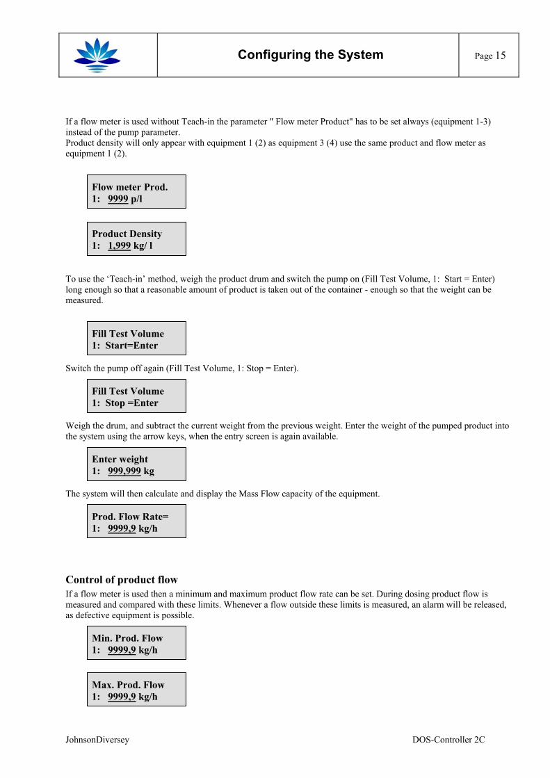
If a flow meter is used without Teach-in the parameter " Flow meter Product" has to be set always (equipment 1-3) instead of the pump parameter. Product density will only appear with equipment 1 (2) as equipment 3 (4) use the same product and flow meter as equipment 1 (2).
Flow meter Prod. 1: 9999 p/l
Product Density 1: 1,999 kg/ l
To use the ‘Teach-in’ method, weigh the product drum and switch the pump on (Fill Test Volume, 1: Start = Enter) long enough so that a reasonable amount of product is taken out of the container - enough so that the weight can be measured.
Fill Test Volume 1: Start=Enter
Switch the pump off again (Fill Test Volume, 1: Stop = Enter).
Fill Test Volume 1: Stop =Enter
Weigh the drum, and subtract the current weight from the previous weight. Enter the weight of the pumped product into the system using the arrow keys, when the entry screen is again available.
Enter weight 1: 999,999 kg
The system will then calculate and display the Mass Flow capacity of the equipment.
Prod. Flow Rate= 1: 9999,9 kg/h
Control of product flow If a flow meter is used then a minimum and maximum product flow rate can be set. During dosing product flow is measured and compared with these limits. Whenever a flow outside these limits is measured, an alarm will be released, as defective equipment is possible.
Min. Prod. Flow 1: 9999,9 kg/h
Max. Prod. Flow 1: 9999,9 kg/h
JohnsonDiversey DOS-Controller 2C
Configuring the System
Page 16
Operation Mode
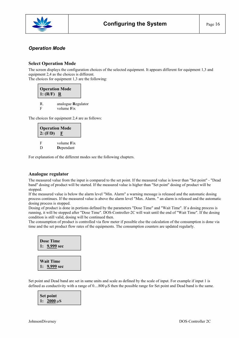
Select Operation Mode The screen displays the configuration choices of the selected equipment. It appears different for equipment 1,3 and equipment 2,4 as the choices is different. The choices for equipment 1,3 are the following:
Operation Mode 1: (R/F) R
R. analogue Regulator F volume Fix
The choices for equipment 2,4 are as follows:
Operation Mode 2: (F/D) F
F volume Fix D Dependant
For explanation of the different modes see the following chapters.
Analogue regulator The measured value from the input is compared to the set point. If the measured value is lower than "Set point" - "Dead band" dosing of product will be started. If the measured value is higher than "Set point" dosing of product will be stopped. If the measured value is below the alarm level "Min. Alarm" a warning message is released and the automatic dosing process continues. If the measured value is above the alarm level "Max. Alarm. " an alarm is released and the automatic dosing process is stopped. Dosing of product is done in portions defined by the parameters "Dose Time" and "Wait Time". If a dosing process is running, it will be stopped after "Dose Time". DOS-Controller-2C will wait until the end of "Wait Time". If the dosing condition is still valid, dosing will be continued then. The consumption of product is controlled via flow meter if possible else the calculation of the consumption is done via time and the set product flow rates of the equipments. The consumption counters are updated regularly.
Dose Time 1: 9.999 sec
Wait Time 1: 9.999 sec
Set point and Dead band are set in same units and scale as defined by the scale of input. For example if input 1 is defined as conductivity with a range of 0....800 µS then the possible range for Set point and Dead band is the same.
Set point 1: 2000 µS
JohnsonDiversey DOS-Controller 2C
Configuring the System
Page 17
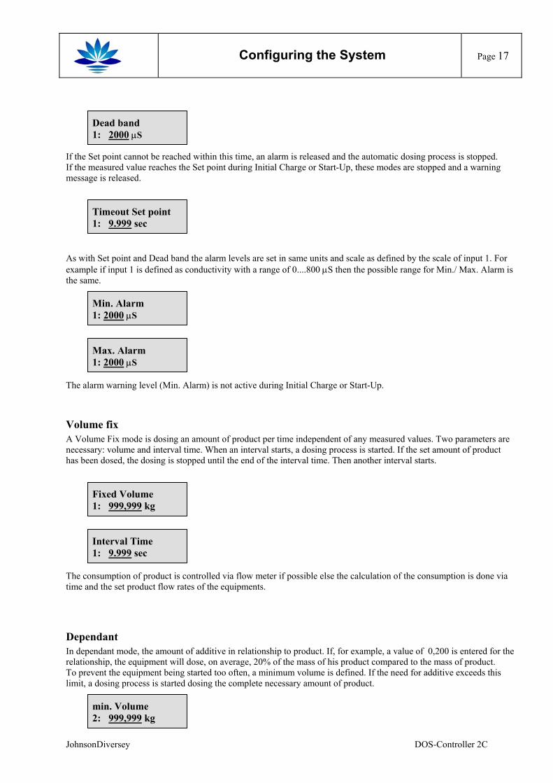
Dead band 1: 2000 µS
If the Set point cannot be reached within this time, an alarm is released and the automatic dosing process is stopped. If the measured value reaches the Set point during Initial Charge or Start-Up, these modes are stopped and a warning message is released.
Timeout Set point 1: 9.999 sec
As with Set point and Dead band the alarm levels are set in same units and scale as defined by the scale of input 1. For example if input 1 is defined as conductivity with a range of 0....800 µS then the possible range for Min./ Max. Alarm is the same.
Min. Alarm 1: 2000 µS
Max. Alarm 1: 2000 µS
The alarm warning level (Min. Alarm) is not active during Initial Charge or Start-Up.
Volume fix A Volume Fix mode is dosing an amount of product per time independent of any measured values. Two parameters are necessary: volume and interval time. When an interval starts, a dosing process is started. If the set amount of product has been dosed, the dosing is stopped until the end of the interval time. Then another interval starts.
Fixed Volume 1: 999,999 kg
Interval Time 1: 9.999 sec
The consumption of product is controlled via flow meter if possible else the calculation of the consumption is done via time and the set product flow rates of the equipments.
Dependant In dependant mode, the amount of additive in relationship to product. If, for example, a value of 0,200 is entered for the relationship, the equipment will dose, on average, 20% of the mass of his product compared to the mass of product. To prevent the equipment being started too often, a minimum volume is defined. If the need for additive exceeds this limit, a dosing process is started dosing the complete necessary amount of product.
min. Volume 2: 999,999 kg
JohnsonDiversey DOS-Controller 2C
Configuring the System
Page 18
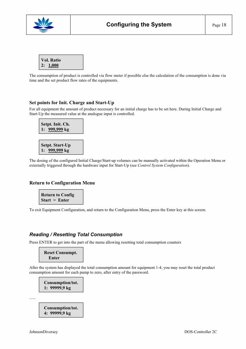
Vol. Ratio 2: 1,000
The consumption of product is controlled via flow meter if possible else the calculation of the consumption is done via time and the set product flow rates of the equipments.
Set points for Init. Charge and Start-Up For all equipment the amount of product necessary for an initial charge has to be set here. During Initial Charge and Start-Up the measured value at the analogue input is controlled.
Setpt. Init. Ch. 1: 999,999 kg
Setpt. Start-Up 1: 999,999 kg
The dosing of the configured Initial Charge/Start-up volumes can be manually activated within the Operation Menu or externally triggered through the hardware input for Start-Up (see Control System Configuration).
Return to Configuration Menu
Return to Config Start = Enter
To exit Equipment Configuration, and return to the Configuration Menu, press the Enter key at this screen.
Reading / Resetting Total Consumption Press ENTER to get into the part of the menu allowing resetting total consumption counters
Reset Consumpt. Enter
After the system has displayed the total consumption amount for equipment 1-4, you may reset the total product consumption amount for each pump to zero, after entry of the password.
Consumption/tot. 1: 99999,9 kg
......
Consumption/tot. 4: 99999,9 kg
JohnsonDiversey DOS-Controller 2C
Configuring the System
Page 19
Although the total consumption is displayed separately for each equipment, resetting will be done simultaneously for all three equipment’s (= products).
Reset Consumpt. Enter
Enter Password xxxx
If a false password is entered, the "Reset Consumption" screen will be shown again.
Network setting If a CAN-Bus interface is equipped, this option appears in the menu.
Network setting Enter
The type of operation in the network has to be selected first.
Use Network (M/S/N): M
Three selections are available:
M Master This DOS-Controller-2C is a Master to another DOS-Controller-2Cs within the same network.
S Slave This DOS-Controller-2C is Slave to another DOS-Controller-2C within the same network N None The CAN-Bus interface will not be used in conjunction with other DOS-Controller-2Cs
Network ID 32
The address within the CAN-Bus has to be set. If the DOS-Controller-2C is selected to be a "Master" then the address has to be a multiple of 2. This master will regard all DOS-Controller-2Cs as slave if their address is higher by 1 compared to his address. Note: If another address is set, it will be reduced to the next lowest multiple of 2. Any address below 3 will not be
accepted Example: If the address is set to be 19 it will be changed automatically to 18 if ENTER is pressed.
If a DOS-Controller-2C is selected to be a "Slave" its address must not be a multiple of two. This slave will regard a DOS-Controller-2C as Master if his address is the next lowest multiple of two compared with his own address. Care must be taken not to assign two slaves to the same address. Note: If a multiple of four is set, the address will be incremented by one.
Example: If the address is set to be 20 it will be changed automatically to 21 if ENTER is pressed. Example: Master = 32, Slave = 33
Changing the Password
Change Password Enter
JohnsonDiversey DOS-Controller 2C
Configuring the System
Page 20
The four-digit password can be changed when a new code is entered twice in a row. When the two entries don’t match, the new password will not be accepted.
Repeat Password xxxx
After entering a false code the system switches back to entry of the password. Note: System is delivered with password 9999, which can be modified!
Input / Output Test
I/O - Test Enter
The reliability of the digital input and output channels of the DOS-Controller-2C system can be tested here (refer to Appendix A for flow chart).
Analogue Input 1: 06,44 mA
Analogue Input 2: 08,28 mA
The input current into both analogue inputs will be displayed first.
Flow sensor 1-8 x x x x x P P P
The status of the flow sensors will be displayed next with ‘1’ indicating a ‘high’, 'P' indicating pulses at the input and ‘0’ indicating a ‘low’ signal level.
Dig. Input 1-8 x x 0 1 0 1 0 0
The status of all digital inputs will be displayed, with ‘1’ indicating a ‘high’, and ‘0’ indicating a ‘low’ signal level.
Set Output 1-8 0 0 0 1 0 1 0 0
Set Output 9-16 x x x x x x 0 0
All digital outputs for the 4 pumps, 4 stroke signals to the pumps and the output for the alarm and the running message can be individually set or reset by toggling between ‘1’ and ‘0’ using the down arrow key. After exiting the Input / Output Test, all previous output signal levels will be restored.
JohnsonDiversey DOS-Controller 2C
Configuring the System
Page 21
Resume Operation
Resume Operation Enter
To exit the Configuration Mode and resume operation in the Automatic Mode, press the Enter key. Immediately upon exiting the Configuration Mode, the system will begin sequencing in Automatic Mode, using the configuration parameters which were last entered.
JohnsonDiversey DOS-Controller 2C
Operating instructions
Page 22
Operating instructions
Operation of DOS-Controller-2C The DOS-Controller-2C starts to operate automatically after power up. Power supply is indicated by an activated LCD-display. No user interaction is necessary after configuration of the DOS-Controller-2C.
Conduct. No Rel. 0234 mS 0225 mS
(Example: DOS-Controller-2C waiting for release trigger) The display always shows the configured input type, the operation mode and the values at both analogue inputs. If the display shows "Automatic" a dosing process is running. A release trigger signal is necessary for automatic operation.
Cond. Autom. 0234 mS 0225 mS
(Example: DOS-Controller-2C dosing automatically) The display may be switched at any time to display of the set point by pressing the "⇒"-key. The display is restored if the key is released.
Set point 0250 mS 0250 mS
The display may be switched at any time to display of the status of all equipment’s by pressing the "⇓"-key. The display is restored if the key is released.
Eq1 Eq2 Eq3 Eq4 R:1 D:0 R:1 F:1
The top line shows all 4 equipments. Below each equipment the operation mode is shown and the actual state of the output: 1 = on, 0 = off. The operation mode is shown with the same abbreviations as used during configuration, for example "R" denotes "regulator mode". The state of the output shows the state of the power output, in case of stroked equipment a "1" will be shown as longs as the output will be active. An individual stroke output will not be shown. For a TD-Control running as master within a network an output will be displayed as "1" (active) if dosing for the master, outputs requested by slaves will not be shown as active here. These will be displayed as active by the slave. If the display shows "Initial Charge", "Start-Up" or "Manual", an additional dosing process is running. A release trigger signal is necessary for automatic operation. To start an Initial Charge or a Start-Up dosing an additional input signal (Initial Charge or Start-Up) is necessary. These modes may be triggered manually too (see below). The configuration can be changed at any time (refer to "Programming the DOS-Controller-2C").
Condi. Init.Ch. 0234 mS 0225 mS
(Example: DOS-Controller-2C dosing an Initial Charge)
JohnsonDiversey DOS-Controller 2C
Operating instructions
Page 23
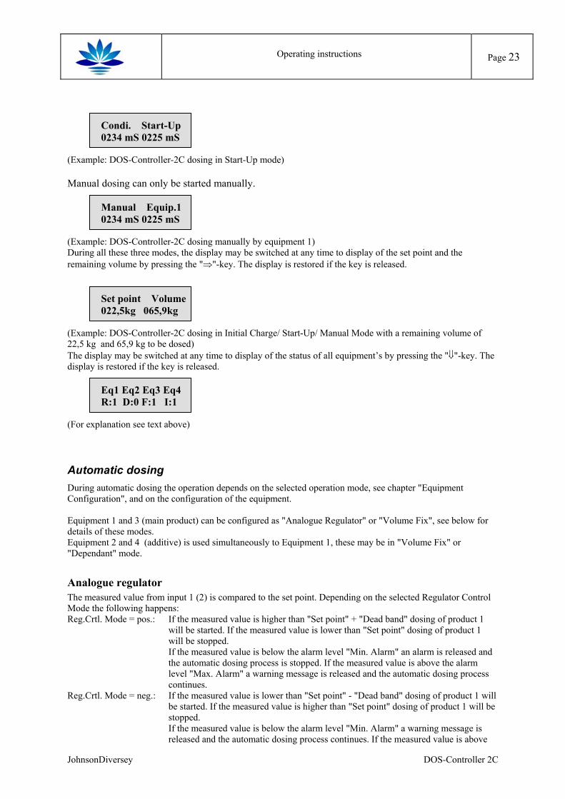
Condi. Start-Up 0234 mS 0225 mS
(Example: DOS-Controller-2C dosing in Start-Up mode) Manual dosing can only be started manually.
Manual Equip.1 0234 mS 0225 mS
(Example: DOS-Controller-2C dosing manually by equipment 1) During all these three modes, the display may be switched at any time to display of the set point and the remaining volume by pressing the "⇒"-key. The display is restored if the key is released.
Set point Volume 022,5kg 065,9kg
(Example: DOS-Controller-2C dosing in Initial Charge/ Start-Up/ Manual Mode with a remaining volume of 22,5 kg and 65,9 kg to be dosed) The display may be switched at any time to display of the status of all equipment’s by pressing the "⇓"-key. The display is restored if the key is released.
Eq1 Eq2 Eq3 Eq4 R:1 D:0 F:1 I:1
(For explanation see text above)
Automatic dosing During automatic dosing the operation depends on the selected operation mode, see chapter "Equipment Configuration", and on the configuration of the equipment. Equipment 1 and 3 (main product) can be configured as "Analogue Regulator" or "Volume Fix", see below for details of these modes. Equipment 2 and 4 (additive) is used simultaneously to Equipment 1, these may be in "Volume Fix" or "Dependant" mode.
Analogue regulator The measured value from input 1 (2) is compared to the set point. Depending on the selected Regulator Control Mode the following happens: Reg.Crtl. Mode = pos.: If the measured value is higher than "Set point" + "Dead band" dosing of product 1
will be started. If the measured value is lower than "Set point" dosing of product 1 will be stopped. If the measured value is below the alarm level "Min. Alarm" an alarm is released and the automatic dosing process is stopped. If the measured value is above the alarm level "Max. Alarm" a warning message is released and the automatic dosing process continues.
Reg.Crtl. Mode = neg.: If the measured value is lower than "Set point" - "Dead band" dosing of product 1 will be started. If the measured value is higher than "Set point" dosing of product 1 will be stopped. If the measured value is below the alarm level "Min. Alarm" a warning message is released and the automatic dosing process continues. If the measured value is above
JohnsonDiversey DOS-Controller 2C
Operating instructions
Page 24
the alarm level "Max. Alarm. " an alarm is released and the automatic dosing process is stopped.
Dosing of product 1 is done in portions defined by the parameters "Dose Time" and "Wait Time". If a dosing process is running, it will be stopped after "Dose Time". DOS-Controller-2C will wait until the end of "Wait Time". If the dosing condition is still valid, dosing will be continued then. The consumption of product is controlled via flow meter if possible else the calculation of the consumption is done via time and the set product flow rates of the equipments. The consumption counters are updated regularly. If the set point cannot be reached within this time, an alarm is released and the automatic dosing process is stopped.
Volume fix A Volume Fix mode is dosing an amount of product per time independent of any measured values. Two parameters are necessary: volume and interval time. When an interval starts, a dosing process is started. If the set amount of product has been dosed, the dosing is stopped until the end of the interval time. Then another interval starts. The consumption of product is controlled via flow meter if possible else the calculation of the consumption is done via time and the set product flow rates of the equipments.
Dependant In dependant mode, the amount of product 2 is set in relationship to product 1. If, for example, a value of 0,200 is entered for the relationship, the equipment will dose, on average, 20% of the mass of his product compared to the mass of product 1. To prevent the equipment being started too often, a minimum volume is defined. If the need for product 2 exceeds this limit, a dosing process is started dosing the complete necessary amount of product. The consumption of product is controlled via flow meter if possible else the calculation of the consumption is done via time and the set product flow rates of the equipments.
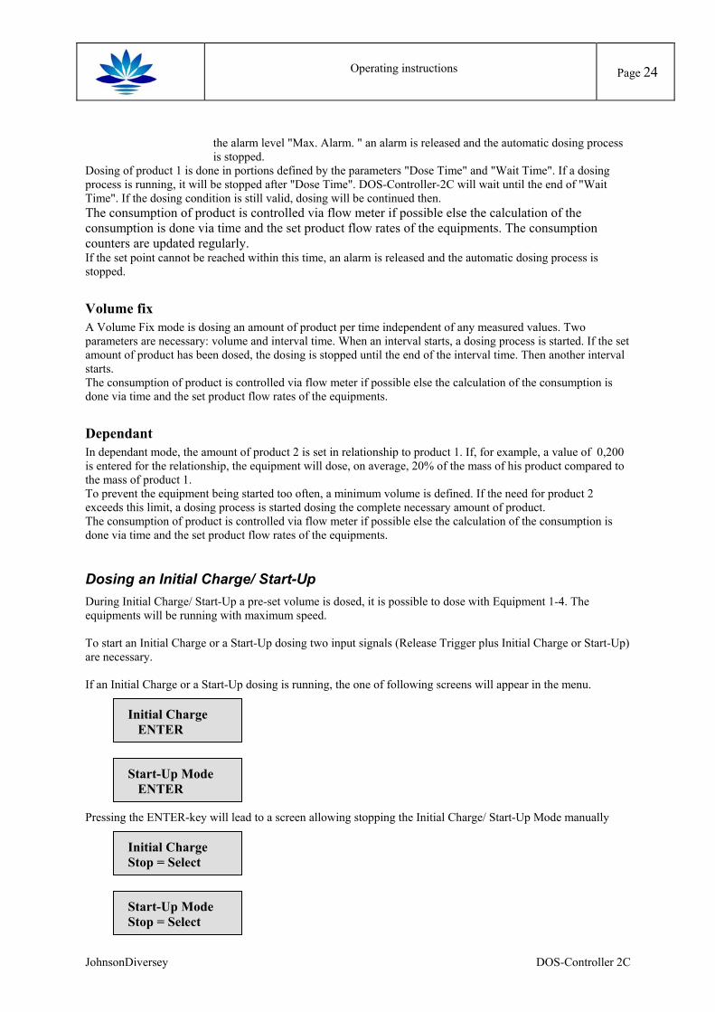
Dosing an Initial Charge/ Start-Up During Initial Charge/ Start-Up a pre-set volume is dosed, it is possible to dose with Equipment 1-4. The equipments will be running with maximum speed. To start an Initial Charge or a Start-Up dosing two input signals (Release Trigger plus Initial Charge or Start-Up) are necessary. If an Initial Charge or a Start-Up dosing is running, the one of following screens will appear in the menu.
Initial Charge ENTER
Start-Up Mode ENTER
Pressing the ENTER-key will lead to a screen allowing stopping the Initial Charge/ Start-Up Mode manually
Initial Charge Stop = Select
Start-Up Mode Stop = Select
JohnsonDiversey DOS-Controller 2C
Operating instructions
Page 25
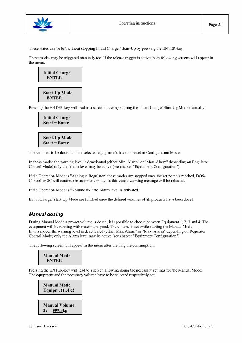
These states can be left without stopping Initial Charge / Start-Up by pressing the ENTER-key These modes may be triggered manually too. If the release trigger is active, both following screens will appear in the menu.
Initial Charge ENTER
Start-Up Mode ENTER
Pressing the ENTER-key will lead to a screen allowing starting the Initial Charge/ Start-Up Mode manually
Initial Charge Start = Enter
Start-Up Mode Start = Enter
The volumes to be dosed and the selected equipment’s have to be set in Configuration Mode. In these modes the warning level is deactivated (either Min. Alarm" or "Max. Alarm" depending on Regulator Control Mode) only the Alarm level may be active (see chapter "Equipment Configuration"). If the Operation Mode is "Analogue Regulator" these modes are stopped once the set point is reached, DOS-Controller-2C will continue in automatic mode. In this case a warning message will be released. If the Operation Mode is "Volume fix " no Alarm level is activated. Initial Charge/ Start-Up Mode are finished once the defined volumes of all products have been dosed.
Manual dosing During Manual Mode a pre-set volume is dosed, it is possible to choose between Equipment 1, 2, 3 and 4. The equipment will be running with maximum speed. The volume is set while starting the Manual Mode In this modes the warning level is deactivated (either Min. Alarm" or "Max. Alarm" depending on Regulator Control Mode) only the Alarm level may be active (see chapter "Equipment Configuration"). The following screen will appear in the menu after viewing the consumption:
Manual Mode ENTER
Pressing the ENTER-key will lead to a screen allowing doing the necessary settings for the Manual Mode: The equipment and the necessary volume have to be selected respectively set:
Manual Mode Equipm. (1..4):2
Manual Volume 2: 999,9kg
JohnsonDiversey DOS-Controller 2C
Operating instructions
Page 26
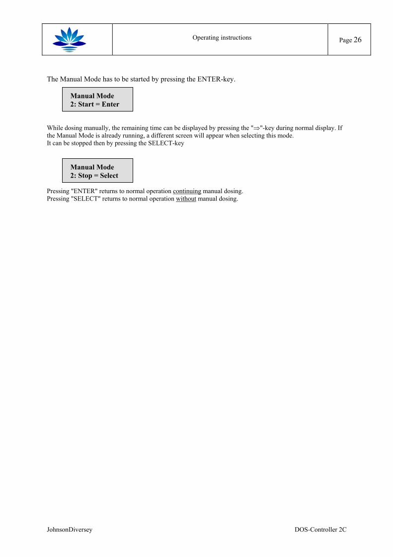
The Manual Mode has to be started by pressing the ENTER-key.
Manual Mode 2: Start = Enter
While dosing manually, the remaining time can be displayed by pressing the "⇒"-key during normal display. If the Manual Mode is already running, a different screen will appear when selecting this mode. It can be stopped then by pressing the SELECT-key
Manual Mode 2: Stop = Select
Pressing "ENTER" returns to normal operation continuing manual dosing. Pressing "SELECT" returns to normal operation without manual dosing.
JohnsonDiversey DOS-Controller 2C
Operating instructions
Page 27
Network operation A DOS-Controller-2C can be run using the CAN-Network in two different modes: In stand-alone mode, the DOS-Controller-2C is exchanging data with a host-PC running the network. Configuration can be done via the network also. Two DOS-Controller-2Cs may be coupled together using the CAN-network to form a "Master-Slave"-network. In this case some rules of operation are necessary: − Every slave will send a request of product to his master if product is needed. The Master will do the same
(internally). − The unit to be serviced first is the unit that sent the first request (FIFO-principle: first in - first out). − During Wait Time (Regulator Mode) another unit may be serviced. − An Initial Charge or a Start-Up Dosing may not be interrupted by another unit.
Operation as "Master" If a DOS-Controller-2C is used as Master the following differences in operation will occur:
− The Master will control the pumps via the configuration of equipment 1 and 2.
− Sensor input 1 will not be used, as the master will only be able to control one bath via equipment 3 and 4. A Master will display only the measured value of channel 2 on the right side of the display. Only sensor 2 can be configured in “sensor configuration”.
− Flow sensors will only be used with equipment 1 and 2; the same applies to the level inputs.
− The equipment 3, 4 will always be "permanent”, as valves will be controlled and not dosing pumps.
− The valves 3-4 corresponding to equipment 3-4 has to be connected to the power outputs, the stroke outputs will be inactive.
Operation as "Slave" If a DOS-Controller-2C is used as Slave the following differences in operation will occur:
− The equipment 1-4 will always be "permanent”, as valves will be controlled and not dosing pumps.
− The valves 1-4 corresponding to equipment 1-4 has to be connected to the power outputs, the stroke outputs will be inactive.
− Level alarm, data of equipment and flow sensor inputs will not be used, these are only necessary for the Master. If the network address of a DOS-Controller-2C is set to a Slave-Address, these items will be skipped during configuration.
JohnsonDiversey DOS-Controller 2C
Troubleshooting
Page 28
Troubleshooting
Alarms and Warnings There are two types of alarm messages: Alarm and Warning. Alarm: The dosing process will be stopped until the alarm is acknowledged by pressing the ENTER-key Warning: DOS-Controller-2C continues with normal operation. The warning message will stay on the until it
is acknowledged by pressing the ENTER-key An alarm/ warning will always be signaled in the top line of the display. If possible, the bottom line will continue to show the measured values at both inputs. The last alarm or warning that occurred will be displayed. If an alarm is activated, no warning message will override this display.
Alarm messages
E3 broken wire 1 - - - - - ??? ???? ??
E3 broken wire 2 - - - - - ??? ???? ??
The input current at input 1 or 2 is lower than 2 mA. This is possible if the input has been defined as 4-20mA input.
E5 Condi. min. ????? ??? ???? ??
The measured value is below the low Alarm threshold (Regulator Control Mode = positive
E5 Condi. max. ????? ??? ???? ??
The measured value is above the high Alarm threshold (Regulator Control Mode = negative)
Setting reached ????? ??? ???? ??
The set point could not be reached within the set time-out limit (Analogue regulator Mode, equipment 1,3 only).
Vol.nt reached X ????? ??? ???? ??
The pre-set volume could not be dosed within the set interval time. (Volume fix Mode). The demand for volume is higher then ten times the pre-set minimum volume (Dependant Mode). "X" denotes the equipment generating this error
JohnsonDiversey DOS-Controller 2C
Troubleshooting
Page 29
E7 Level Alarm X ????? ??? ???? ??
The level alarm input of product "X" has been activated (X=1, 2). An alarm is generated if the level alarm input is activated and the related equipment/ product are needed.
Warning messages
W1 Low Flow Pr.X ????? ??? ???? ??
The flow of product "X" has been measured and is below the set minimum flow, the warning has been activated (X=1, 2).
W2 High Flow Pr.X ????? ??? ???? ??
The flow of product "X" has been measured and is above the set maximum flow, the warning has been activated (X=1, 2).
W5 Cond. min. ????? ??? ???? ??
The measured value is below the low warning threshold (Regulator Control Mode = negative).
W5 Cond. max. ????? ??? ???? ??
The measured value is above the high warning threshold (Regulator Control Mode = positive)
W7 Level Alarm X ????? ??? ???? ??
The level alarm input of product "X" has been activated (X=1, 2). A warning is generated if the level alarm input is activated and the related equipment/ product are not needed. This error exists as warning and alarm. As longs, as a product is not demanded, no alarm is generated because a Master not needing this product should not be stopped by a level alarm of this product. In case of a product rarely needed, the equipment may continue working as long as no actual demand appears.
JohnsonDiversey DOS-Controller 2C
Troubleshooting
Page 30
System Not Functional If no display appears on the LCD screen when the system is switched on:
• check all electrical connections
• ensure that all fuses are functioning
• ensure that the power supply has not been disrupted
If the system still does not function, please contact the service department. If the display is working, check inputs and the reaction of the outputs with the integrated "I/O-Test" function
JohnsonDiversey DOS-Controller 2C
Example
Page 31
Example
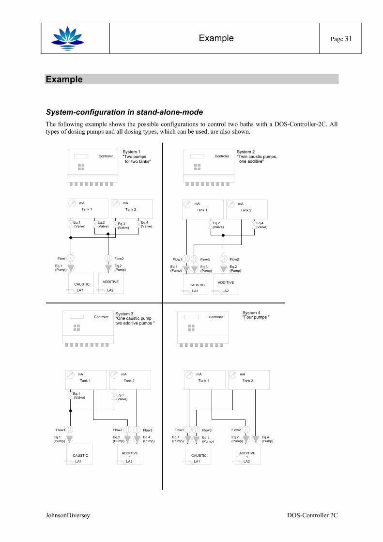
System-configuration in stand-alone-mode The following example shows the possible configurations to control two baths with a DOS-Controller-2C. All types of dosing pumps and all dosing types, which can be used, are also shown.
Controler
Eq.3 (Valve)
Eq.1 (Valve)
Eq.1 (Pump)
Flow1
LA1
mA
Eq.2 (Valve)
Eq.2 (Pump)
Flow2
LA2
mA
Eq.4 (Valve)
CAUSTICADDITIVE
Tank 1 Tank 2
Eq.3 (Pump)
Flow3
Eq.1 (Pump)
Flow1
LA1
mA
Eq.2 (Valve)
Eq.2 (Pump)
Flow2
LA2
mA
Eq.4 (Valve)
CAUSTICADDITIVE
Tank 1 Tank 2
Eq.3 (Pump)
Flow3
Eq.1 (Pump)
Flow1
LA1
mA
Eq.2 (Pump)
Flow2
LA2
mA
Eq.4 (Pump)
CAUSTICADDITIVE
1
Tank 1 Tank 2
Eq.3 (Valve)
Flow3
Eq.1 (Valve)
Eq.1 (Pump)
Flow1
LA1
mA
Eq.2 (Pump)
Flow2
LA2
mA
Eq.4 (Pump)
CAUSTICADDITIVE
1
Tank 1 Tank 2
Controler
ControlerControlerSystem 1"Two pumps for two tanks"
System 2"Twin caustic pumps, one additive"
System 4"Four pumps "
System 3"One caustic pumptwo additive pumps "
JohnsonDiversey DOS-Controller 2C
Example
Page 32
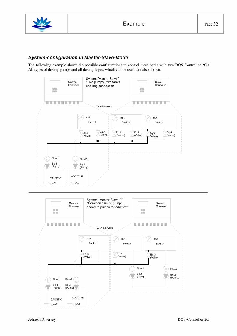
System-configuration in Master-Slave-Mode The following example shows the possible configurations to control three baths with two DOS-Controller-2C's All types of dosing pumps and all dosing types, which can be used, are also shown.
Eq.3 (Valve)
Eq.1 (Pump)
Flow1
LA1
Eq.2 (Pump)
Flow2
LA2
mA
Eq.4 (Valve)
CAUSTICADDITIVE
Tank 1
System "Master-Slave""Two pumps, two tanksand ring connection"
Eq.3 (Valve)
Eq.1 (Valve)
mA
Eq.2 (Valve)
mA
Eq.4 (Valve)
Tank 2 Tank 3
Master-Controler
Slave-Controler
CAN-Network
Eq.3 (Valve)
Eq.1 (Pump)
Flow1
LA1
Eq.2 (Pump)
Flow2
LA2
mA
CAUSTICADDITIVE
Tank 1
System "Master-Slave-2""Common caustic pump;seoarate pumps for additive"
Eq.3 (Valve)
Eq.1 (Valve)
mA mA
Tank 2 Tank 3
Master-Controler
Slave-Controler
CAN-Network
Eq.1 (Pump)
Flow1
Eq.2 (Pump)
Flow2
JohnsonDiversey DOS-Controller 2C
Example
Page 33
There is the prerequisite that the dosing pumps are gauged the capacity by litres. (Please refer to manual). Let us assume the following values: Equipment No.: chemical name: dosing type: dosing capacity: 1 caustic timed dosing 260l/h 2 additive timed dosing 3l/h This leads to the following configuration: Equipment parameters: description 1 description 2 equipment
1 equipment 2 equipment
3 equipment 4
equipment description caustic additive caustic additive chemical name for the dosed liquid:
NaOH
Divo Ultra
NaOH
Divo Ultra
equipment mode (I/O) P P V Vproduct flow meter (Y/N) Y Y N Npump type STROKE DOSING
PERMAN. DOSING
X X
pulse/pause timers for stroke dosing
On time: Off time:
s s
0.20.2
timed pump capacity l/h 260.0 stroke pump capacity p/l 3,0 flow meter product p/l 50 density kg/l 1.33 1.33 product flow min flow
max flow kg/h kg/h
150.0600.0
operation mode: R/C/F/D R D R Fregulated dosing time
wait time set point dead band timeout set point reg. mode (pos/neg) min alarm max alarm
s s s
2060
110mS10mS1800neg.
70mS130mS
10 60
050mS 05mS 1800 neg.
35mS 65mS
volume fix fixed volume interval time
kg s
0.1900
dependent min volume volume ratio
kg 0.0050.100
initial charge set point kg 1.5 0.2 1,0 0.1start up set point kg 1.0 0.1 0,7 0.1 Explanation of the configuration above: Bath1, Product 1 Automatic: Dosage is ‘analogue-controlled’ and has its set point at 110 mS. Due to the dead band of 10 mS and
the negative sense of control, dosage is started at ‘actual value < 100 mS’ and is finished at ‘actual value > 110 mS’. Dosage runs with pulse/pause steps of 20/60 sec. A prerequisite is that releases are given, i.e. have high-signal. A warning min - message is given out on the display if the actual value is below 70 mS, but dosing doesn’t stop. The dosing process will be stopped if actual value is higher than 130 mS.
Initial charge: in order to be able to start an initial charge, release must be given. Then the desired volume of 1,5 kg is directly dosed.
Start up: the same behavior as initial charge, but only a volume of 1,0 kg is dosed. Manual: at manual dosage, a fixed volume of caustic, which have to be written to the controller, would be dosed
in the bath via equipment 1 (260l/h).
JohnsonDiversey DOS-Controller 2C
Example
Page 34
Bath 1, Product 2 Automatic: for this process, depending dosage is selected. A ratio of 10% is desired to be controlled to process 1.
This means, caustic/additive = 10/1. Additive dosage will only begin, if a volume to be dosed is more than 5g, calculated via the set ratio. This is controlled by the ‘min volume’ function. If, e.g. during a dosing process, a volume of 40g caustic has been dosed, the dosage of the additive will still be suppressed. As soon as the 50g limit will be exceeded due to a further dosage and the ratio is 10%, the dosage of 5g additive will be carried out.
Initial charge: At an initial charge, the maintenance-dosing pump (equipment 2) would deliver the demanded volume of 0,2 kg.
Start up: the maintenance-dosing pump (equipment 2) doses the same behavior as initial charge, but only a volume of 0,1 kg.
Manual: At manual dosage a free volume additive would be dosed in the bath via equipment 2. Bath2, Product 1 Automatic: Dosage is ‘analogue-controlled’ and has its set point at 55 mS. Due to the dead band of 5 mS and the
negative sense of control, dosage is started at ‘actual value < 50 mS’ and is finished at ‘actual value > 55 mS’. Dosage runs with pulse/pause steps of 10/60 sec. A prerequisite is that releases are given, i.e. have high signal. A warning min - message is given out on the display if the actual value is below 35 mS, but dosing doesn’t stop. The dosing process will be stopped if actual value is higher than 65 mS.
Initial charge: in order to be able to start an initial charge, release must be given. Then the desired volume of 1,0 kg is directly dosed.
Start up: the same behavior as initial charge, but only a volume of 0,7 kg is dosed. Manual: at manual dosage, a fixed volume of caustic, which have to be written to the controller, would be dosed
in the bath via equipment 1 (260l/h). Bath 2, Product 2 Automatic: This process is done independent from another process with ‘Timed Fixed’ dosage. This means, as
soon as release signal is given, it will be dosed continuously every 3600 sec a volume of 0,1 kg. During dosage, the DOS-Controller-2C sends pulse/pause signals with a length of 0,2/0,and 2s to the stroke pump.
Initial charge: An initial charge, 0,1 kg here, will only be started with release and done with dosing pump 2. Again, strokes for the pump are used.
Start up: the dosing pump doses the same behavior as initial charge, 0,1 kg. Manual: At manual dosage a free volume additive would be dosed in bath 2 via equipment 2.
JohnsonDiversey DOS-Controller 2C
Appendix
Page 35
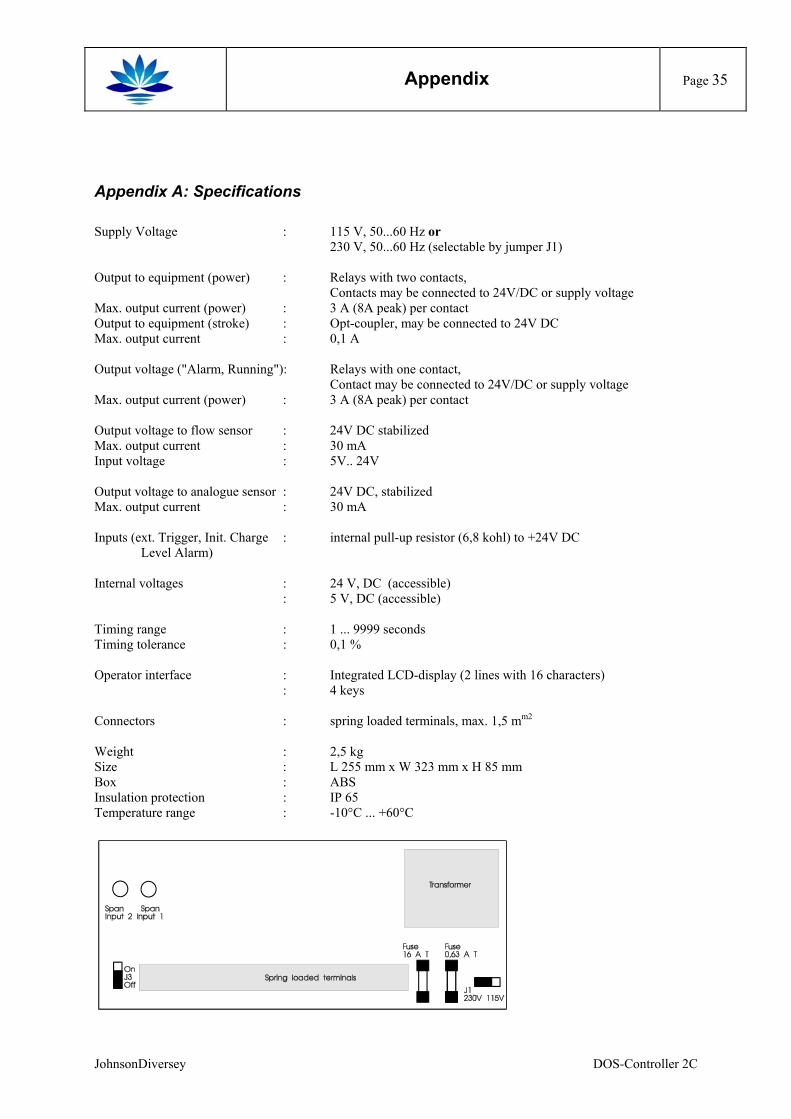
Appendix A: Specifications Supply Voltage : 115 V, 50...60 Hz or 230 V, 50...60 Hz (selectable by jumper J1) Output to equipment (power) : Relays with two contacts, Contacts may be connected to 24V/DC or supply voltage Max. output current (power) : 3 A (8A peak) per contact Output to equipment (stroke) : Opt-coupler, may be connected to 24V DC Max. output current : 0,1 A Output voltage ("Alarm, Running"): Relays with one contact, Contact may be connected to 24V/DC or supply voltage Max. output current (power) : 3 A (8A peak) per contact Output voltage to flow sensor : 24V DC stabilized Max. output current : 30 mA Input voltage : 5V.. 24V Output voltage to analogue sensor : 24V DC, stabilized Max. output current : 30 mA Inputs (ext. Trigger, Init. Charge : internal pull-up resistor (6,8 kohl) to +24V DC Level Alarm) Internal voltages : 24 V, DC (accessible) : 5 V, DC (accessible) Timing range : 1 ... 9999 seconds Timing tolerance : 0,1 % Operator interface : Integrated LCD-display (2 lines with 16 characters) : 4 keys Connectors : spring loaded terminals, max. 1,5 mm2 Weight : 2,5 kg Size : L 255 mm x W 323 mm x H 85 mm Box : ABS Insulation protection : IP 65 Temperature range : -10°C ... +60°C
JohnsonDiversey DOS-Controller 2C
Appendix
Page 36
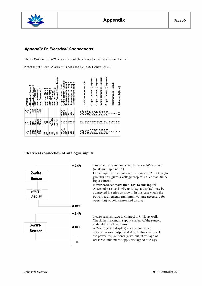
Appendix B: Electrical Connections The DOS-Controller-2C system should be connected, as the diagram below: Note: Input “Level Alarm 3” is not used by DOS-Controller 2C
C_L
PEC_
HC_
LPE
C_H
GND
AI1+
+24V
GND
AI2+
+24V
GND
Flow
1+2
4VGN
DFl
ow2
+24V
GND
Flow
3+2
4V
0VLA
10V
LA2
0VLA
30V
Star
t-Up
0VIn
it.Ch
.0V
ext.
Rel.
PE PE PE PE PE PE PE PE PE PE PE PE PE PE PE PE PE PE PE PE PE PE PE
GND
GND
GND
GND
+24V
+24V
+24V
+24V
Alm
_AAl
m_B
Run_
ARu
n_B
S1E
S1C
S2E
S2C
S3E
S3C
S4E
S4C
P_1A
P_1A
P1_B
P_1B
P_2A
P_2A
P_2B
P_2B
P_3A
P_3A
P_3B
P_3B
P_4A
P_4A
P_4B
P_4B
NL
NL
NL
NL
NL1
CAN-
Bus
4-20
mA-
Inpu
t Sen
sor 1
4-20
mA-
Inpu
t Sen
sor 2
Inpu
t Flo
wsen
sor 1
Inpu
t Flo
wsen
sor 3
Inpu
t Flo
wsen
sor 2
Inpu
t Lev
el Al
arm
1
Inpu
t Lev
el Al
arm
1In
put L
evel
Alar
m 1
Inpu
t "St
art-U
p"In
put "
Initi
al Ch
arge
"In
put "
exte
rnal
Relea
se T
rigge
r"
Outp
ut co
ntac
t "Al
arm
"Ou
tput
cont
act "
Runn
ing"
Stro
ke o
utpu
t to
pum
p 1
Stro
ke o
utpu
t to
pum
p 4
Stro
ke o
utpu
t to
pum
p 3
Stro
ke o
utpu
t to
pum
p 2
24V/
DC te
rmin
als (o
utpu
t)
Main
s ter
min
als (o
utpu
t)
Main
s sup
ply (
inpu
t)
Outp
ut co
ntac
ts (2
) to
pum
p 1
Outp
ut co
ntac
ts (2
) to
pum
p 4
Outp
ut co
ntac
ts (2
) to
pum
p 3
Outp
ut co
ntac
ts (2
) to
pum
p 1
Electrical connection of analogue inputs
2-wireSensor
2-wireDisplay
+24V
AIx+
3-wireSensor
+24V
AIx+
JohnsonDiversey
2-wire sensors are connected between 24V and Aix (analogue input no. X). Direct input with an internal resistance of 270 Ohm (to ground), this gives a voltage drop of 5.4 Volt at 20mA input current. Never connect more than 12V to this input! A second passive 2-wire unit (e.g. a display) may be connected in series as shown. In this case check the power requirements (minimum voltage necessary for operation) of both sensor and display.
3-wire sensors have to connect to GND as well. Check the maximum supply current of the sensor, it should be below 30mA. A 2-wire (e.g. a display) may be connected between sensor output and Alx. In this case check the power requirements (max. output voltage of sensor vs. minimum supply voltage of display).
DOS-Controller 2C
Appendix
Page 37
Electrical connection of Level Alarm inputs
2-wire=contact
4-wire=Optocoupler
+24V
flowx
flowx
3-wire=Hall-Sensor
+24V
flowx
2-wire=Output
flowx
2.7k
2.7k
2.7k
2.7k+24V
+24V
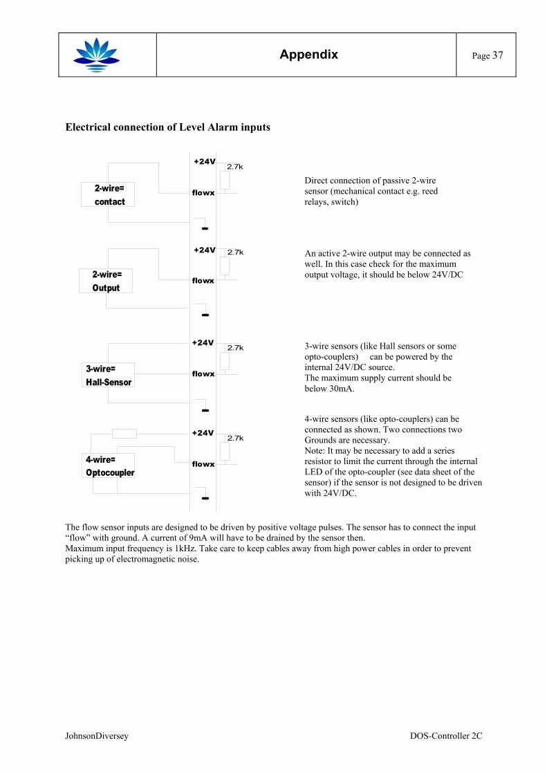
Direct connection of passive 2-wire sensor (mechanical contact e.g. reed relays, switch)
An active 2-wire output may be connected as well. In this case check for the maximum output voltage, it should be below 24V/DC
3-wire sensors (like Hall sensors or some opto-couplers) can be powered by the internal 24V/DC source. The maximum supply current should be below 30mA.
4-wire sensors (like opto-couplers) can be connected as shown. Two connections two Grounds are necessary. Note: It may be necessary to add a series resistor to limit the current through the internal LED of the opto-coupler (see data sheet of the sensor) if the sensor is not designed to be driven with 24V/DC.
The flow sensor inputs are designed to be driven by positive voltage pulses. The sensor has to connect the input “flow” with ground. A current of 9mA will have to be drained by the sensor then. Maximum input frequency is 1kHz. Take care to keep cables away from high power cables in order to prevent picking up of electromagnetic noise.
JohnsonDiversey DOS-Controller 2C
Appendix
Page 38
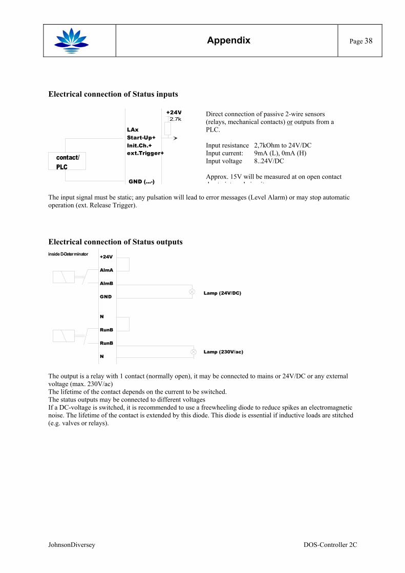
Electrical connection of Status inputs
LAxStart-Up+Init.Ch.+ext.Trigger+
contact/PLC
GND (...-)
2.7k+24V
The input signal must be static; any pulsation will lead tooperation (ext. Release Trigger).
Electrical connection of Status outputs
+24V
AlmA
AlmB
GND
N
RunB
RunB
N
inside D-Determinator
The output is a relay with 1 contact (normally open), it mvoltage (max. 230V/ac) The lifetime of the contact depends on the current to be The status outputs may be connected to different voltageIf a DC-voltage is switched, it is recommended to use a noise. The lifetime of the contact is extended by this dio(e.g. valves or relays).
JohnsonDiversey
Direct connection of passive 2-wire sensors (relays, mechanical contacts) or outputs from a PLC. Input resistance 2,7kOhm to 24V/DC Input current: 9mA (L), 0mA (H) Input voltage 8..24V/DC Approx. 15V will be measured at on open contact d t i t l i it
error messages (Level Alarm) or may stop automatic
Lamp (24V/DC)
Lamp (230V/ac)
ay be connected to mains or 24V/DC or any external
switched. s freewheeling diode to reduce spikes an electromagnetic de. This diode is essential if inductive loads are stitched
DOS-Controller 2C
Appendix
Page 39
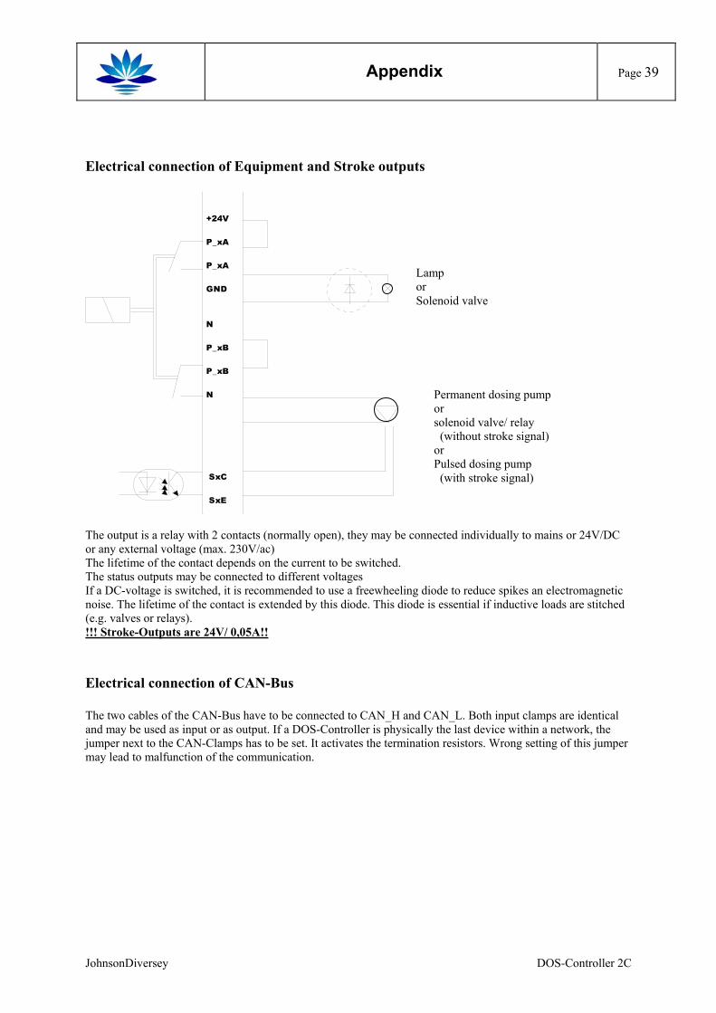
Electrical connection of Equipment and Stroke outputs
+24V
P_xA
P_xA
GND
N
P_xB
P_xB
N
SxC
SxE
Lamp or Solenoid valve
Permanent dosing pump or solenoid valve/ relay (without stroke signal) or Pulsed dosing pump (with stroke signal)
The output is a relay with 2 contacts (normally open), they may be connected individually to mains or 24V/DC or any external voltage (max. 230V/ac) The lifetime of the contact depends on the current to be switched. The status outputs may be connected to different voltages If a DC-voltage is switched, it is recommended to use a freewheeling diode to reduce spikes an electromagnetic noise. The lifetime of the contact is extended by this diode. This diode is essential if inductive loads are stitched (e.g. valves or relays). !!! Stroke-Outputs are 24V/ 0,05A!!
Electrical connection of CAN-Bus The two cables of the CAN-Bus have to be connected to CAN_H and CAN_L. Both input clamps are identical and may be used as input or as output. If a DOS-Controller is physically the last device within a network, the jumper next to the CAN-Clamps has to be set. It activates the termination resistors. Wrong setting of this jumper may lead to malfunction of the communication.
JohnsonDiversey DOS-Controller 2C
Appendix
Page 40
Appendix C: Menu Schemes
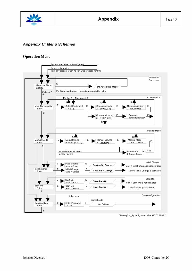
Operation Menu
From configurationfrom any screen when no key was pressed for 60s
Status or Alarmdisplay Do Automatic Mode
View Consumption Enter
Select Equipment(1-4): 2
Consumption/tot.2: 99999,9 kg
Consumption/day2: 999,999 kg
Manual Mode Enter
Manual ModeEquipm. (1..4): 2
Manual Vol.=123,42:Stop = Select
when Manual Mode isalready active
Initial charge Enter
Configuration Enter
Enter Password xxxx
correct code
false code
S
S
S
E E
E E E
S/E
E
if alarm: ES
S
E E E E
System start when not configured
Goto configuration
AutomaticOperation
Consumption
Manual Mode
Diversey\dd_light\dd_menu1.drw 320.03.1998 2
Consumption/day2: Reset = Enter
Do resetconsumption/day
E E
Go Offline
Initial ChargeStop = Select
E
Initial Charge
only if Initial Charge is activatedS
Manual Volume2: 999,9 kg
Manual Mode 2: Start = Enter E
Equip.>3 Equipment+1
S
S
S S
S S
Stop Initial Charge
Start-Up Enter
Start-UpStop = Select
E
Start-Up
only if Start-Up is activatedS Stop Start-Up
For Status and Alarm display types see table below
only if Initial Charge is not activated
only if Start-Up is not activatedStart-UpStart = Enter
E E Start Start-Up
Initial Charge Start = Enter
E E Start Initial Charge
JohnsonDiversey DOS-Controller 2C
Appendix
Page 41
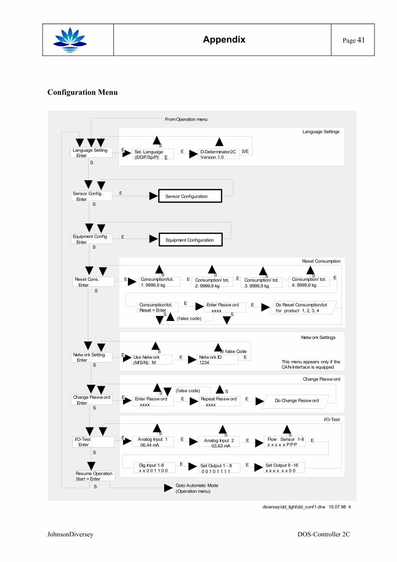
Configuration Menu
To Operationfrom any screen w hen no key w as pressed for 60s
Reset Cons. Enter
Consumption/tot.1: 9999,9 kg
Change Passw ord Enter
I/O-Test Enter
S
S
S
E E E
From Operation menu
Reset Consumption
diversey\dd_light\dd_conf1.drw 15.07.98 4
Enter Passw ord xxxx
Repeat Passw ord xxxx
Do Change Passw ordE E E
Change Passw ord
S S
Analog Input 1 06,44 mA
Set Output 1 - 8 0 0 1 0 1 1 1 1
E E
I/O-Test
S
Resume OperationStart = Enter
S
Enter Passw ord xxxx
Do Reset Consumption/totfor product 1, 2, 3, 4
E
E
Consumption/ tot.3: 9999,9 kg
Set Output 9 -16x x x x x x 0 0
E
ES
Flow Sensor 1-8x x x x x P P P
ES
Analog Input 2 03,63 mA
Dig.Input 1-8x x 0 0 1 1 0 0
E
S S S
S
Consumption/tot.Reset = Enter
E
S
Equipment Config Enter
S
Sensor Config. Enter
S
Equipment ConfigurationE
Goto Automatic Mode (Operation menu)
(false code)
(false code)
Language Setting Enter
Sel. Language(E/D/F/Sp/P): E
D-Determinator2CVersion 1.0
E E S/E
Language Settings
S
S
Consumption/ tot.4: 9999,9 kg
SConsumption/ tot.2: 9999,9 kg
Sensor ConfigurationE
Netw ork Setting Enter
S
EThis menu appears only if theCAN-Interface is equipped
Use Netw ork(M/S/N): M
Netw ork ID1234
E E
Netw ork Settings
S S/ false Code
JohnsonDiversey DOS-Controller 2C
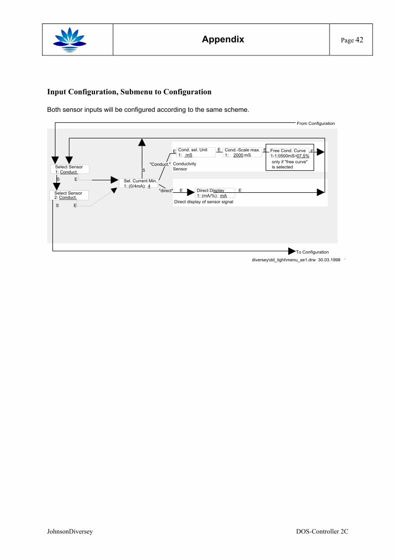
Appendix
Page 42
Input Configuration, Submenu to Configuration Both sensor inputs will be configured according to the same scheme.
Select Sensor1: Conduct.
E
S E
From Configuration
ConductvitySensor
diversey\dd_light\menu_se1.drw 30.03.1998 1
Cond.-Scale max.1: 2000 mS
Cond. sel. Unit1: mS
E EFree Cond. Curve1-1:0500mS=07,5%only if "free curve"is selected
Direct display of sensor signal
Direct Display1: (mA/%): mA
E E
"Conduct."
"direct"
Sel. Current Min.1: (0/4mA): 4
S
E E
Select Sensor2: Conduct.
S E
To Configuration
JohnsonDiversey DOS-Controller 2C
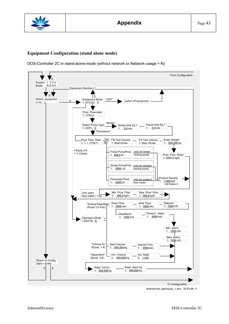
Appendix
Page 43
Equipment Configuration (stand alone mode) DOS-Controller 2C in stand-alone-mode (without network or Network-usage = N)
Select equipment(1-4): 1
"Stroke"
S
From Configuration
switch off equipmentE "OFF"
To Configuration
Product Density1: 1,999 kg/l
Prod. Flow Rate 1: T. I. (Y/N):Y
Fill Test Volume1: Start=Enter
Enter Weight1: 999,999 kg
Fill Test Volume1: Stop =Enter
YesNo
Setpoint1: 1999 mS
Wait Time1: 9999 sec
Timeout - Setpt. 1: 9999 sec
Deadband1: 1999 mS
Interval Time 1: 9999 sec
fixed Volume1: 999,999 kg
"Analog Regulator"(Equip.1/3 only)
Dose Time1: 9999 sec
Setpt. Init.Ch.1: 999,999 kg
Max. Alarm1: 1999 mS
Min. Alarm1: 1999 mS
Equipm.: 1 2 3 4Mode: R D R F
S
Vol. Ratio2: 1,000
"dependant"(Equip. 2/4)
min. Volume2: 999,999 kg
Return to Config.Start = Enter
Stroke time Eq.11: 9,9 sec
diversey\dd_light\equip_1.drw 30.03.98 2
Pause time Eq.11: 9,9 sec
Equipment Mode1: (P/V/O): P
S
"Permanent"
Select Pump Type1: (S/P): S
Timed PumpProd.1: 999,9 l/h
Stroke PumpProd.1: 9999 p/l
Flowmeter Prod..1: 9999 p/l
only for timeddosing pump
only for strokeddosing pump
only for productflow meter
"Volume fix"(Equip. 1-4)
Equipment Number+1
Prod. Flowmeter 1: (Y/N):Y
Prod. Flow Rate=1: 9999,9 kg/h
Operation Mode1:(R/F/D): R
not Equip.3
Max. Prod. Flow1: 999,9 kg/h
Min. Prod. Flow1: 999,9 kg/h
only when flow meter = Yes
S E
if Equip.3/4= V (Valve)
Setpt. Start-Up1: 999,999 kg
JohnsonDiversey DOS-Controller 2C
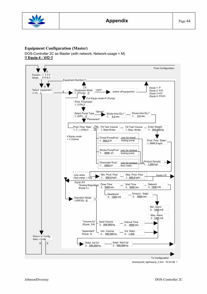
Appendix
Page 44
Equipment Configuration (Master) DOS-Controller 2C as Master (with network, Network-usage = M) !! Equip.4 : V/O !!
Select equipment(1-4): 1
"Stroke"
S
From Configuration
switch off equipmentE "OFF"
To Configuration
Product Density1: 1,999 kg/l
Prod. Flow Rate 1: T. I. (Y/N):Y
Fill Test Volume1: Start=Enter
Enter Weight1: 999,999 kg
Fill Test Volume1: Stop =Enter
YesNo
Setpoint3: 1999 mS
Wait Time3: 9999 sec
Timeout - Setpt. 3: 9999 sec
Deadband3: 1999 mS
Interval Time 3: 9999 sec
fixed Volume3: 999,999 kg
"Analog Regulator"(Equip.3 )
Dose Time3: 9999 sec
Setpt. Init.Ch.3: 999,999 kg
Max. Alarm3: 1999 mS
Min. Alarm3: 1999 mS
Equipm.: 1 2 3 4Mode: P P R F
S
Vol. Ratio4: 1,000
"dependant"(Equip. 4)
min. Volume4: 999,999 kg
Return to Config.Start = Enter
Stroke time Eq.11: 9,9 sec
diversey\dd_light\equip_2.drw 03.04.98 1
Pause time Eq.11: 9,9 sec
Equipment Mode1: (P/V/O): P
S
"Permanent"
Select Pump Type1: (S/P): S
Timed PumpProd.1: 999,9 l/h
Stroke PumpProd.1: 9999 p/l
Flowmeter Prod..1: 9999 p/l
only for timeddosing pump
only for strokeddosing pump
only for productflow meter
"Volume fix"(Equip. 3/4)
Equipment Number+1
Prod. Flowmeter 1: (Y/N):Y
Prod. Flow Rate=1: 9999,9 kg/h
Operation Mode1:(R/F/D): R
Equip.1/2Max. Prod. Flow1: 999,9 kg/h
Min. Prod. Flow1: 999,9 kg/h
only when flow meter = Yes
S E
if Equip.mode= V (Valve)
Setpt. Start-Up3: 999,999 kg
if of Equip.mode=P (Pump)
Equip.3/4
Equip.1: PEquip.2: P/OEquip.3:V/OEquip.4: P/V/O
JohnsonDiversey DOS-Controller 2C
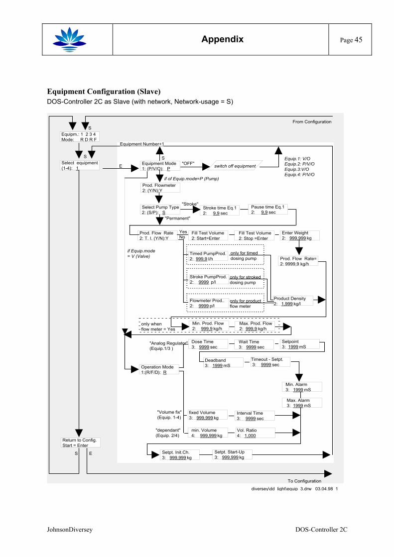
Appendix
Page 45
Equipment Configuration (Slave) DOS-Controller 2C as Slave (with network, Network-usage = S)
Select equipment(1-4): 1
"Stroke"
S
From Configuration
switch off equipmentE "OFF"
To Configuration
Product Density2: 1,999 kg/l
Prod. Flow Rate 2: T. I. (Y/N):Y
Fill Test Volume2: Start=Enter
Enter Weight2: 999,999 kg
Fill Test Volume2: Stop =Enter
YesNo
Setpoint3: 1999 mS
Wait Time3: 9999 sec
Timeout - Setpt. 3: 9999 sec
Deadband3: 1999 mS
Interval Time 3: 9999 sec
fixed Volume3: 999,999 kg
"Analog Regulator"(Equip.1/3 )
Dose Time3: 9999 sec
Setpt. Init.Ch.3: 999,999 kg
Max. Alarm3: 1999 mS
Min. Alarm3: 1999 mS
Equipm.: 1 2 3 4Mode: R D R F
S
Vol. Ratio4: 1,000
"dependant"(Equip. 2/4)
min. Volume4: 999,999 kg
Return to Config.Start = Enter
Stroke time Eq.12: 9,9 sec
diversey\dd_light\equip_3.drw 03.04.98 1
Pause time Eq.12: 9,9 sec
Equipment Mode1: (P/V/O): P
S
"Permanent"
Select Pump Type2: (S/P): S
Timed PumpProd.2: 999,9 l/h
Stroke PumpProd.2: 9999 p/l
Flowmeter Prod..2: 9999 p/l
only for timeddosing pump
only for strokeddosing pump
only for productflow meter
"Volume fix"(Equip. 1-4)
Equipment Number+1
Prod. Flowmeter 2: (Y/N):Y
Prod. Flow Rate=2: 9999,9 kg/h
Operation Mode1:(R/F/D): R
Max. Prod. Flow2: 999,9 kg/h
Min. Prod. Flow2: 999,9 kg/h
only when flow meter = Yes
S E
if Equip.mode= V (Valve)
Setpt. Start-Up3: 999,999 kg
if of Equip.mode=P (Pump)
Equip.1: V/OEquip.2: P/V/OEquip.3:V/OEquip.4: P/V/O
JohnsonDiversey DOS-Controller 2C
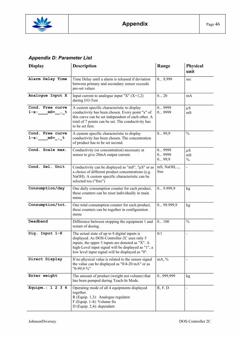
Appendix
Page 46
Appendix D: Parameter List Display Description Range Physical
unit Alarm Delay Time Time Delay until a alarm is released if deviation
between primary and secondary sensor exceeds pre-set values
0... 9,999 sec
Analogue Input X Input current to analogue input "X" (X=1,2) during I/O-Test
0... 20 mA
Cond. Free curve 1-x:____mS=__,_%
A custom specific characteristic to display conductivity has been chosen. Every point "x" of this curve can be set independent of each other. A total of 7 points can be set. The conductivity has to be set first.
0... 9999 0... 9999
µS mS
Cond. Free curve 1-x:____mS=_,_%
A custom specific characteristic to display conductivity has been chosen. The concentration of product has to be set second.
0... 99,9 %
Cond. Scale max. Conductivity (or concentration) necessary at sensor to give 20mA output current.
0... 9999 0... 9999 0... 99,9
µS mS %
Cond. Sel. Unit Conductivity can be displayed as "mS", "µS" or as a choice of different product concentrations (e.g. NaOH). A custom specific characteristic can be selected too ("free")
mS, NaOH,..., free
-
Consumption/day One daily consumption counter for each product, these counters can be reset individually in main menu
0... 9.999,9 kg
Consumption/tot. One total consumption counter for each product, these counters can be together in configuration menu
0... 99.999,9 kg
Deadband Difference between stopping the equipment 1 and restart of dosing.
0... 100 %
Dig. Input 1-8 The actual state of up to 8 digital inputs is displayed. As DOS-Controller-2C uses only 5 inputs, the upper 3 inputs are denoted as "X". A high-Level input signal will be displayed as "1", a low level input signal will be displayed as "0".
0/1 -
Direct Display If no physical value is related to the sensor signal the value can be displayed as "0/4-20 mA" or as "0-99,9 %"
mA, % -
Enter weight The amount of product (weight not volume) that has been pumped during Teach-In Mode.
0...999,999 kg
Equipm.: 1 2 3 4 Operating mode of all 4 equipments displayed together. R (Equip. 1,3): Analogue regulator F (Equip. 1-4): Volume fix D (Equip. 2,4): dependant
R, F, D -
JohnsonDiversey DOS-Controller 2C
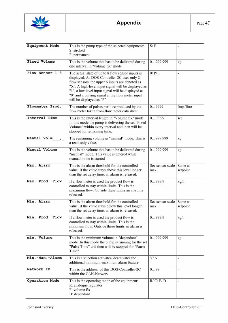
Appendix
Page 47
Equipment Mode This is the pump type of the selected equipment: S: stroked P: permanent
S/ P -
Fixed Volume This is the volume that has to be delivered during one interval in "volume fix" mode
0... 999,999 kg
Flow Sensor 1-8 The actual state of up to 8 flow sensor inputs is displayed. As DOS-Controller-2C uses only 2 flow sensors, the upper 6 inputs are denoted as "X". A high-level input signal will be displayed as "1", a low level input signal will be displayed as "0" and a pulsing signal at the flow meter input will be displayed as "P"
0/ P/ 1 -
Flowmeter Prod. The number of pulses per litre produced by the flow meter taken from flow meter data sheet
0... 9999 Imp./litre
Interval Time This is the interval length in "Volume fix" mode. In this mode the pump is delivering the set "Fixed Volume" within every interval and then will be stopped for remaining time.
0... 9.999 sec
Manual Vol=___,_ The remaining volume in "manual" mode. This is a read-only value.
0... 999,999 kg
Manual Volume This is the volume that has to be delivered during "manual" mode. This value is entered while manual mode is started
0... 999,999 kg
Max. Alarm This is the alarm threshold for the controlled value. If the value stays above this level longer than the set delay time, an alarm is released.
See sensor scale max.
Same as setpoint
Max. Prod. Flow If a flow meter is used the product flow is controlled to stay within limits. This is the maximum flow. Outside these limits an alarm is released.
0... 999,9 kg/h
Min. Alarm This is the alarm threshold for the controlled value. If the value stays below this level longer than the set delay time, an alarm is released.
See sensor scale max.
Same as setpoint
Min. Prod. Flow If a flow meter is used the product flow is controlled to stay within limits. This is the minimum flow. Outside these limits an alarm is released.
0... 999,9 kg/h
min. Volume This is the minimum volume in "dependant" mode. In this mode the pump is running for the set "Pulse Time" and then will be stopped for "Pause Time".
0... 999,999 kg
Min.-Max.-Alarm This is a selection activates/ deactivates the additional minimum-maximum alarm feature
Y/ N -
Network ID This is the address of this DOS-Controller-2C within the CAN-Network
0... 99 -
Operation Mode This is the operating mode of the equipment: R. analogue regulator F: volume fix D: dependant
R/ C/ F/ D -
JohnsonDiversey DOS-Controller 2C
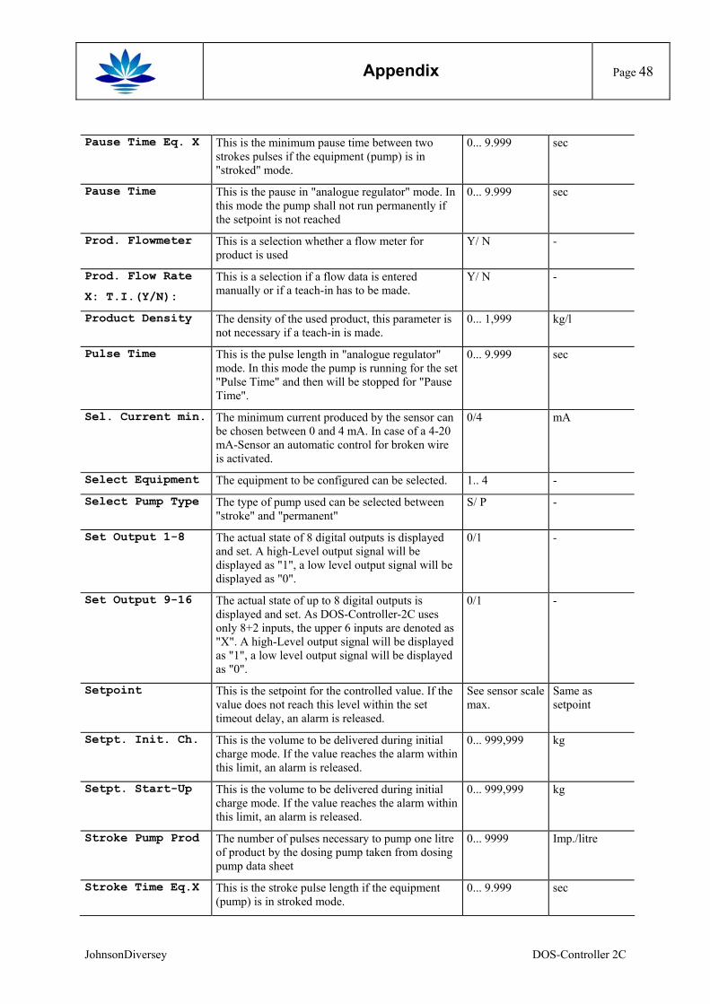
Appendix
Page 48
Pause Time Eq. X This is the minimum pause time between two strokes pulses if the equipment (pump) is in "stroked" mode.
0... 9.999 sec
Pause Time This is the pause in "analogue regulator" mode. In this mode the pump shall not run permanently if the setpoint is not reached
0... 9.999 sec
Prod. Flowmeter This is a selection whether a flow meter for product is used
Y/ N -
Prod. Flow Rate
X: T.I.(Y/N):
This is a selection if a flow data is entered manually or if a teach-in has to be made.
Y/ N -
Product Density The density of the used product, this parameter is not necessary if a teach-in is made.
0... 1,999 kg/l
Pulse Time This is the pulse length in "analogue regulator" mode. In this mode the pump is running for the set "Pulse Time" and then will be stopped for "Pause Time".
0... 9.999 sec
Sel. Current min. The minimum current produced by the sensor can be chosen between 0 and 4 mA. In case of a 4-20 mA-Sensor an automatic control for broken wire is activated.
0/4 mA
Select Equipment The equipment to be configured can be selected. 1.. 4 -
Select Pump Type The type of pump used can be selected between "stroke" and "permanent"
S/ P -
Set Output 1-8 The actual state of 8 digital outputs is displayed and set. A high-Level output signal will be displayed as "1", a low level output signal will be displayed as "0".
0/1 -
Set Output 9-16 The actual state of up to 8 digital outputs is displayed and set. As DOS-Controller-2C uses only 8+2 inputs, the upper 6 inputs are denoted as "X". A high-Level output signal will be displayed as "1", a low level output signal will be displayed as "0".
0/1 -
Setpoint This is the setpoint for the controlled value. If the value does not reach this level within the set timeout delay, an alarm is released.
See sensor scale max.
Same as setpoint
Setpt. Init. Ch. This is the volume to be delivered during initial charge mode. If the value reaches the alarm within this limit, an alarm is released.
0... 999,999 kg
Setpt. Start-Up This is the volume to be delivered during initial charge mode. If the value reaches the alarm within this limit, an alarm is released.
0... 999,999 kg
Stroke Pump Prod The number of pulses necessary to pump one litre of product by the dosing pump taken from dosing pump data sheet
0... 9999 Imp./litre
Stroke Time Eq.X This is the stroke pulse length if the equipment (pump) is in stroked mode.
0... 9.999 sec
JohnsonDiversey DOS-Controller 2C

Appendix
Page 49
Timed Pump Prod. The flow of product by the dosing pump at full speed taken from dosing pump data sheet
0... 999,9 Litre/h
Timeout Setpt. If the setpoint is not reached within this time, a warning is released.
0... 9.999 sec
Volume Ratio The ratio between product delivered by equipment 1 and equipment 2/4 in "dependant" mode
0... 1,000 -
JohnsonDiversey DOS-Controller 2C
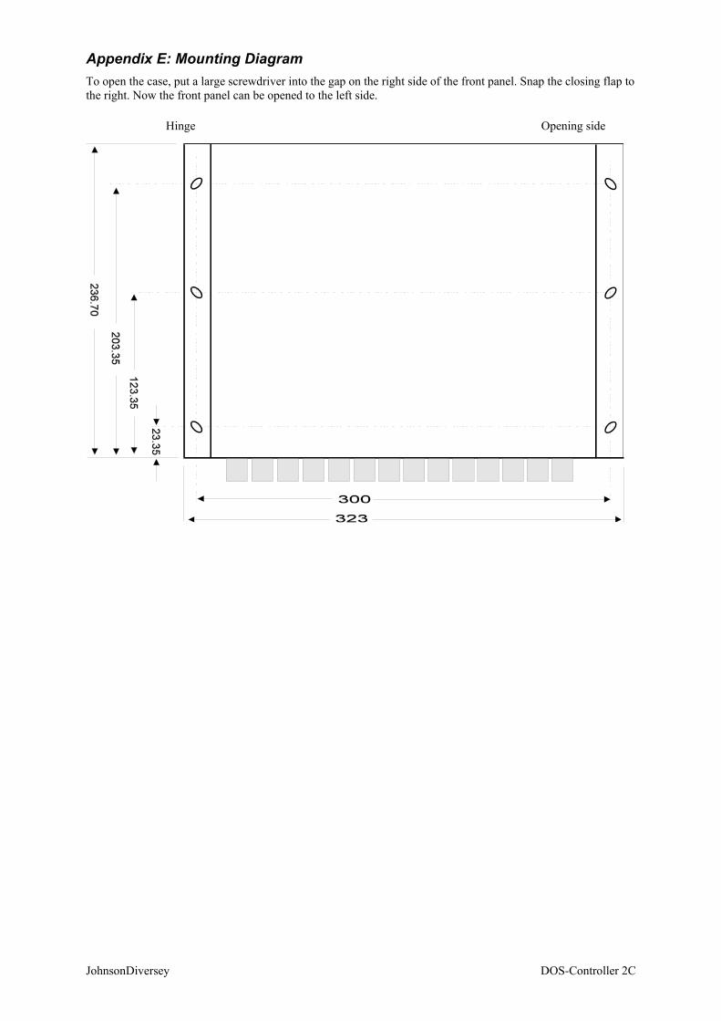
Appendix E: Mounting Diagram To open the case, put a large screwdriver into the gap on the right side of the front panel. Snap the closing flap to the right. Now the front panel can be opened to the left side.
Hinge Opening side
JohnsonDiversey DOS-Controller 2C
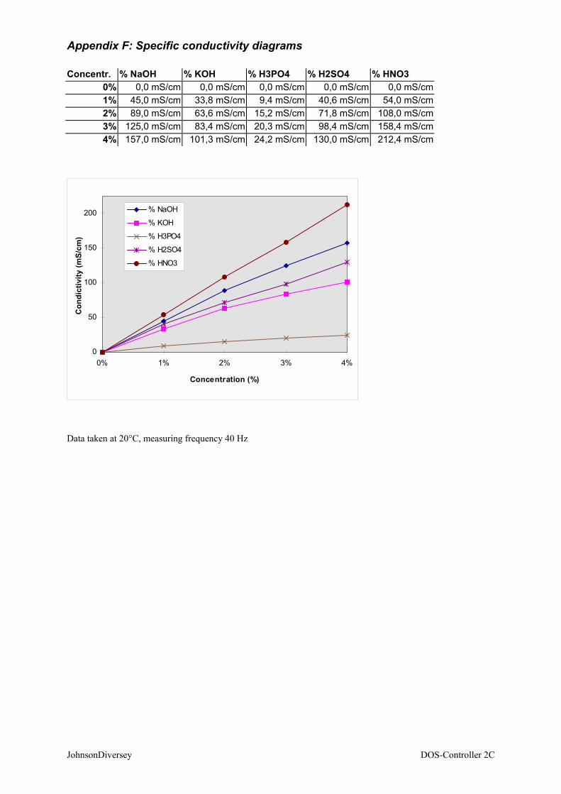
Appendix F: Specific conductivity diagrams Concentr. % NaOH % KOH % H3PO4 % H2SO4 % HNO3
0% 0,0 mS/cm 0,0 mS/cm 0,0 mS/cm 0,0 mS/cm 0,0 mS/cm 1% 45,0 mS/cm 33,8 mS/cm 9,4 mS/cm 40,6 mS/cm 54,0 mS/cm 2% 89,0 mS/cm 63,6 mS/cm 15,2 mS/cm 71,8 mS/cm 108,0 mS/cm 3% 125,0 mS/cm 83,4 mS/cm 20,3 mS/cm 98,4 mS/cm 158,4 mS/cm 4% 157,0 mS/cm 101,3 mS/cm 24,2 mS/cm 130,0 mS/cm 212,4 mS/cm
0
50
100
150
200
0% 1% 2% 3% 4%
Concentration (%)
Con
dict
ivity
(mS/
cm)
% NaOH
% KOH
% H3PO4
% H2SO4
% HNO3
Data taken at 20°C, measuring frequency 40 Hz
JohnsonDiversey DOS-Controller 2C

JohnsonDiversey DOS-Controller 2C
Glossary