Embed Size (px)
Citation preview

Dornier Do 335All Wood Short Kit
a Radio Controlled Modelin 1/10 Scale
Design by Gary Hethcoatbased on the original design
by Al Masters
Copyright 2007Aviation Research
P.O. Box 9192, San Jose, CA 95157http://www.wingsontheweb.comEmail: [email protected]
Phone: 408-660-0943

Dornier Do 335 Building Guide
Table of Contents 1 General Building Notes.......................................................................................4
1.1 Getting Help.................................................................................................4 1.2 Laser Cut Parts.............................................................................................4 1.3 Adhesives......................................................................................................4 1.4 Electronics....................................................................................................4 1.5 Building Options...........................................................................................4
1.5.1 Two Seater and B-series........................................................................4 1.5.2 Retracts..................................................................................................5
1.6 Glow Power...................................................................................................5 1.7 Motor/Speed Controller Choices .................................................................5 1.8 Building Guide Illustrations & Photos..........................................................5
2 Fuselage Construction........................................................................................6 2.1 Forward Hatch..............................................................................................6 2.2 Laying down the Crutch and Upper Formers...............................................7 2.3 Upper Fuselage Stringers..........................................................................12
2.3.1 F9 Installation......................................................................................12 2.4 Sheeting the Upper Fuselage.....................................................................14 2.5 Removable Upper Tail Section...................................................................15 2.6 Stab Construction.......................................................................................19 2.7 Lower Fuselage Construction.....................................................................21
3 Wing Construction.............................................................................................30 3.1 Rib Doubler Laminations............................................................................30 3.2 Rib 0 and 1 alignment................................................................................31 3.3 Wing Leading Edge Installation.................................................................33 3.4 Spar Installation.........................................................................................33 3.5 Joining the Wing Panels..............................................................................35 3.6 Wing Assembly and Alignment...................................................................36 3.7 Wing Dihedral Braces.................................................................................37 3.8 Retract Plates.............................................................................................38 3.9 Finishing the lower wing............................................................................39 3.10 Aligning and Finishing the Wing..............................................................39
4 Finishing............................................................................................................40 4.1 Finishing Methods......................................................................................40 4.2 Paint & Markings........................................................................................40
5 Trimming for Flight...........................................................................................41 5.1 Center of Gravity........................................................................................41 5.2 Balancing Method.......................................................................................41 5.3 Recommended Control Throws..................................................................41 5.4 Power Setup...............................................................................................41
6 Flying the Do 335..............................................................................................42
Page 2

Dornier Do 335 Building Guide
6.1 General Flying Characteristics...................................................................42 6.2 Aerobatics...................................................................................................42 6.3 Ground “sit”................................................................................................42 6.4 More Info....................................................................................................42
6.4.1 RCSB Thread........................................................................................42 6.4.2 Yahoo Group “Do335”..........................................................................42 6.4.3 Phone and “Snail Mail”........................................................................42
Page 3

Dornier Do 335 Building Guide
1 General Building NotesThis model features mostly conventional construction methods and so should present few problems to the experienced builder. This is not a beginner's model. If you have limited building and/or flying experience, it is strongly recommended that you start with a more appropriate model and work up to the Do 335.
1.1 Getting HelpIf you need help or advice, please don't hesitate to contact us. Email and phone are listed on the title page.
1.2 Laser Cut PartsMost of the laser cut parts can be gently broken free of the sheet. Be careful, though, some parts will come out cleaner if you cut through the little “breaks” with a hobby knife before removing the part from the sheet. This is particularly true of the lightening holes in the ribs and the more fragile balsa parts. For best results, place the parts sheet on a cutting board and cut through all the “breaks” in the laser cuts before removing the parts from their sheets.
1.3 AdhesivesCA glue is fine for balsa to balsa and balsa to lite ply. For high stress areas and ply to ply joints, epoxy is recommended unless otherwise specified.
1.4 ElectronicsIf this is your first high-powered electric model, proceed with extreme caution when handling, soldering and connecting batteries and speed controllers. A short or reversed connection can FRY some very delicate and expensive equipment! When soldering connectors onto LiPo batteries, work with one wire at a time and make sure the other is well insulated. Shorting these batteries will cause damage, and it is very easy to do if you work with both wires at the same time. Make absolutely sure you have the connections right before applying battery power to the speed controller.
1.5 Building Options
1.5.1 Two Seater and B-seriesDrawings are shown on the plans for the two-seat version (A-12, etc) of the Do 335. No parts are provided however. The Do 335 B-series canopy and cannon are also shown on the plans.
Page 4
Dornier Do 335 Building Guide
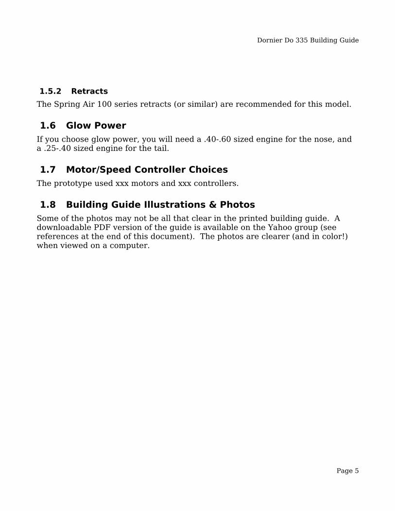
1.5.2 RetractsThe Spring Air 100 series retracts (or similar) are recommended for this model.
1.6 Glow PowerIf you choose glow power, you will need a .40-.60 sized engine for the nose, and a .25-.40 sized engine for the tail.
1.7 Motor/Speed Controller Choices The prototype used xxx motors and xxx controllers.
1.8 Building Guide Illustrations & PhotosSome of the photos may not be all that clear in the printed building guide. A downloadable PDF version of the guide is available on the Yahoo group (see references at the end of this document). The photos are clearer (and in color!) when viewed on a computer.
Page 5

Dornier Do 335 Building Guide
2 Fuselage Construction 2.1 Forward Hatch
The forward hatch is removable for access behind the firewall. It is also a good place to house the receiver and its battery. Glue F1, F2 and F3 square to F6 as shown in Figure 1. The top of the hatch needs to be slightly curved to achieve scale shape, see the plans. You can either wet the sheeting to conform or strip plank this area. A spine (F1A) is provided to help with this. F1, F2 & F3 have notches that can be cut out to install stringers on either side to support the curved sheeting.If you want to simplify construction and you don't care about scale shape, omit F1A and the stringers. Use the non-scale version of F2 marked “F2NS”.
Page 6
Figure 1: Forward Hatch Assembly
Dornier Do 335 Building Guide
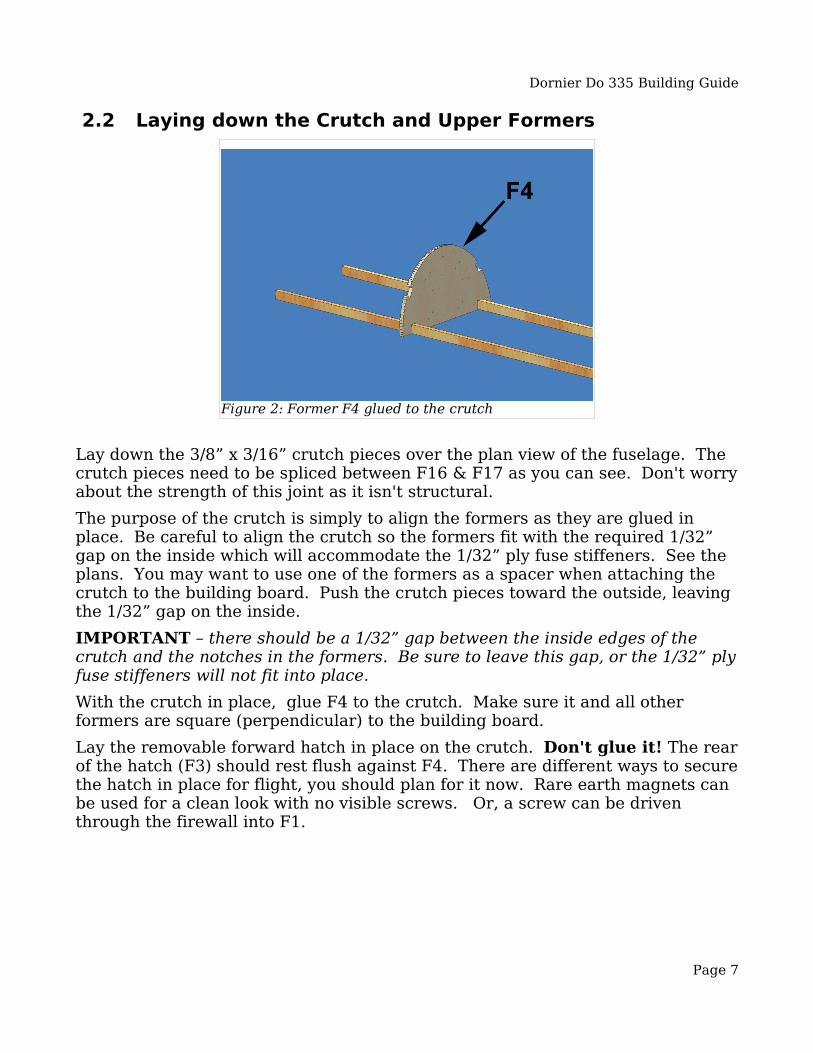
2.2 Laying down the Crutch and Upper Formers
Lay down the 3/8” x 3/16” crutch pieces over the plan view of the fuselage. The crutch pieces need to be spliced between F16 & F17 as you can see. Don't worry about the strength of this joint as it isn't structural.The purpose of the crutch is simply to align the formers as they are glued in place. Be careful to align the crutch so the formers fit with the required 1/32” gap on the inside which will accommodate the 1/32” ply fuse stiffeners. See the plans. You may want to use one of the formers as a spacer when attaching the crutch to the building board. Push the crutch pieces toward the outside, leaving the 1/32” gap on the inside.IMPORTANT – there should be a 1/32” gap between the inside edges of the crutch and the notches in the formers. Be sure to leave this gap, or the 1/32” ply fuse stiffeners will not fit into place.With the crutch in place, glue F4 to the crutch. Make sure it and all other formers are square (perpendicular) to the building board.Lay the removable forward hatch in place on the crutch. Don't glue it! The rear of the hatch (F3) should rest flush against F4. There are different ways to secure the hatch in place for flight, you should plan for it now. Rare earth magnets can be used for a clean look with no visible screws. Or, a screw can be driven through the firewall into F1.
Page 7
Figure 2: Former F4 glued to the crutch

Dornier Do 335 Building Guide
Next glue former F8 to the crutch. Its position isn't critical and most of it will be cut away later if you install a scale cockpit interior.
Glue F10 to the crutch. F10 is a key former, so align it carefully over the plans and make sure it is square to the building board. The wing attaches to the lower half of F10. There is a cutout in F10 which should not be removed yet.
Page 8
Figure 4: Gluing F8 to the crutch
Figure 3: Placing the hatch on the crutch

Dornier Do 335 Building Guide
Glue F11 and F12 to the crutch. The alignment of F11-F18 isn't as critical, but they should still be square to the building board.
Next glue formers F13 – F18 to the crutch. The alignment of former F19 is important. It forms the mating face for the removable upper tail section. Make sure it is square to the building board, flat and true.
Page 9
Figure 5: Gluing F10 to the crutch
Figure 6: Gluing F11 & F12 to the crutch

Dornier Do 335 Building Guide
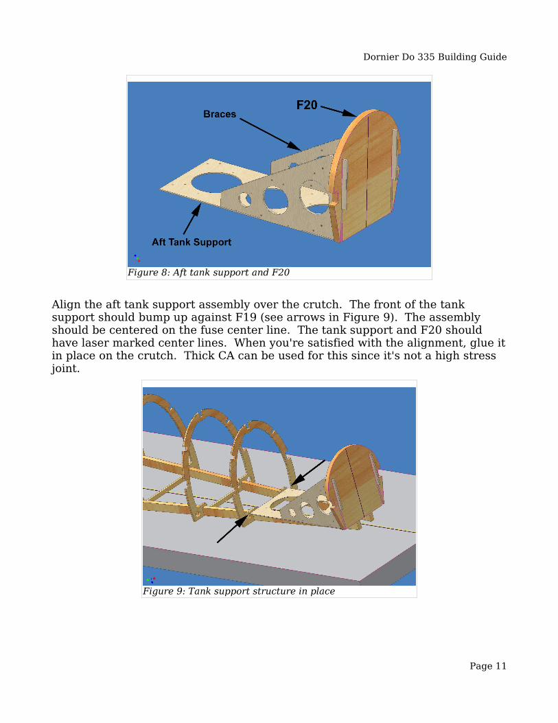
As you begin construction on the aft part of the airframe, keep in mind that weight back here is critical. Keep the tail light and you will have a lighter, better flying model. Since there is already a motor, propeller, etc. back here, you can't afford any extra weight.Assemble the aft tank & firewall support as shown. The laser marked center lines should be on top where they're visible, you'll need them later for alignment. Use epoxy (sparingly here) for ply to ply joints. F20 is a lamination of two 3/32” balsa parts to make one 3/16” part. Laminate it with thick CA. The tabs on the braces should go all the way through F20 and the aft firewall (AFW). They should protrude 1/8” from F20 as shown.
Page 10
Figure 7: Formers F13 - F19
Dornier Do 335 Building Guide
Align the aft tank support assembly over the crutch. The front of the tank support should bump up against F19 (see arrows in Figure 9). The assembly should be centered on the fuse center line. The tank support and F20 should have laser marked center lines. When you're satisfied with the alignment, glue it in place on the crutch. Thick CA can be used for this since it's not a high stress joint.
Page 11
Figure 8: Aft tank support and F20
Figure 9: Tank support structure in place
Dornier Do 335 Building Guide
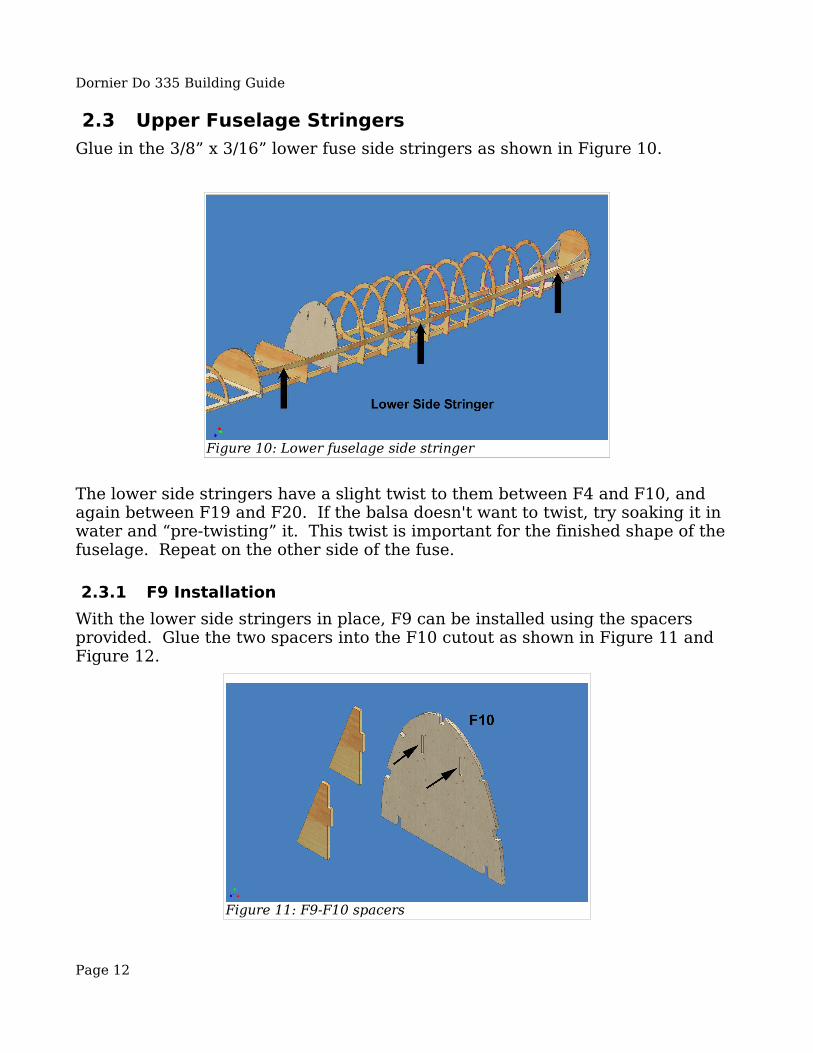
2.3 Upper Fuselage StringersGlue in the 3/8” x 3/16” lower fuse side stringers as shown in Figure 10.
The lower side stringers have a slight twist to them between F4 and F10, and again between F19 and F20. If the balsa doesn't want to twist, try soaking it in water and “pre-twisting” it. This twist is important for the finished shape of the fuselage. Repeat on the other side of the fuse.
2.3.1 F9 InstallationWith the lower side stringers in place, F9 can be installed using the spacers provided. Glue the two spacers into the F10 cutout as shown in Figure 11 and Figure 12.
Page 12
Figure 10: Lower fuselage side stringer
Figure 11: F9-F10 spacers

Dornier Do 335 Building Guide
The spacers and the cutout in F10 will be removed after assembly. The spacers are just to ensure correct alignment of F9. With the spacers in place, glue F9 to the lower side stringers. Do not glue F9 to the spacers!
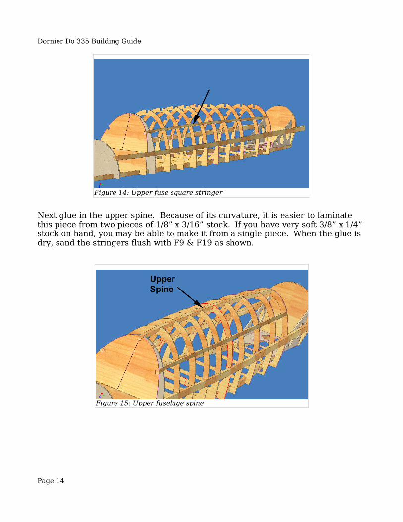
Next glue the 3/16” square upper fuse stringers in place as shown in Figure 14. Repeat for the other side. When these stringers are in place, you can remove the cutout and spacers from F10. This cutout also contains the rectangular wing hold-down plate for the fuselage. Break it out and keep it. You can discard the rest of the cutout and the spacers.
Page 13
Figure 12: F10 with spacers
Figure 13: F9 Installation
Dornier Do 335 Building Guide
Next glue in the upper spine. Because of its curvature, it is easier to laminate this piece from two pieces of 1/8” x 3/16” stock. If you have very soft 3/8” x 1/4” stock on hand, you may be able to make it from a single piece. When the glue is dry, sand the stringers flush with F9 & F19 as shown.
Page 14
Figure 15: Upper fuselage spine
Figure 14: Upper fuse square stringer
Dornier Do 335 Building Guide
2.4 Sheeting the Upper FuselageThere are at least two different methods for sheeting a curved fuselage like this. Since it contains slight compound curves, you will either need to strip plank it or sheet it in sections. Sheet the upper fuse from F9 to F19, down to the middle of the lower 3/8” x 3/16” stringer, on both sides. This step is IMPORTANT! Sheeting the upper fuse at this time stiffens it and prevents it from twisting after it's removed from the building board. If the fuselage twists, you will have a much harder time aligning the wing and tail later.You should also sheet the forward fuselage from F7 forward. The best way to do this is as follows. Place a piece of saran wrap (thin plastic food wrapping) between F3 and F4. The forward hatch is removable, remember? Don't permanently glue it. Tack glue the forward hatch to the crutch. This can be done with a few small drops of thick CA on each side. Wrap the plastic wrap around F4 and sheet the removable hatch. Overlap the sheeting on all sides, you can trim it later. The front sheeting needs to overlap the firewall, so make sure you leave enough for that. You will notice that F2 is slightly higher than F1 or F3. This is because this part of the nose had a slight curvature. This is scale, see the plans. If you wet the balsa you should be able to make it conform when gluing it down. If you want to simplify this part, you can sand down F2 so that the curvature is removed.When the glue is dry, remove the hatch from the crutch by cutting through the glued spots. Trim and sand the sheeting, but leave the front alone, you'll trim it flush with the firewall later. The sheeting should be trimmed flush with F3 and F5.
2.5 Removable Upper Tail SectionThe upper tail is removable to allow for access to the inside of the rear fuselage, which is quite busy with control linkage to the elevators and rudders. For glow power you will also have throttle linkage and a fuel tank in this area. For electric power, you will have motor wires through here. It will still make your life easier to have access to the control linkage and behind the firewall.The cardinal rule with the Do 335 is to keep the tail as light as possible! It's very easy to end up with a lot of weight back here. If this happens, you will need a lot of ballast in the nose resulting in a heavy model. Resist the temptation to use a heavy engine back here.Start by laying out the stab base plate and upper tail post. The upper post, as shown in , is square to the stab base. Align it into the notches and glue sparingly with epoxy.
Page 15

Dornier Do 335 Building Guide
Next glue the upper two parts of stab rib S1 to the stab plate as shown in . The middle part should fit into the notches in the stab plate. Notice the gap between S1 and the upper tail post. The spar will fit in this gap later.
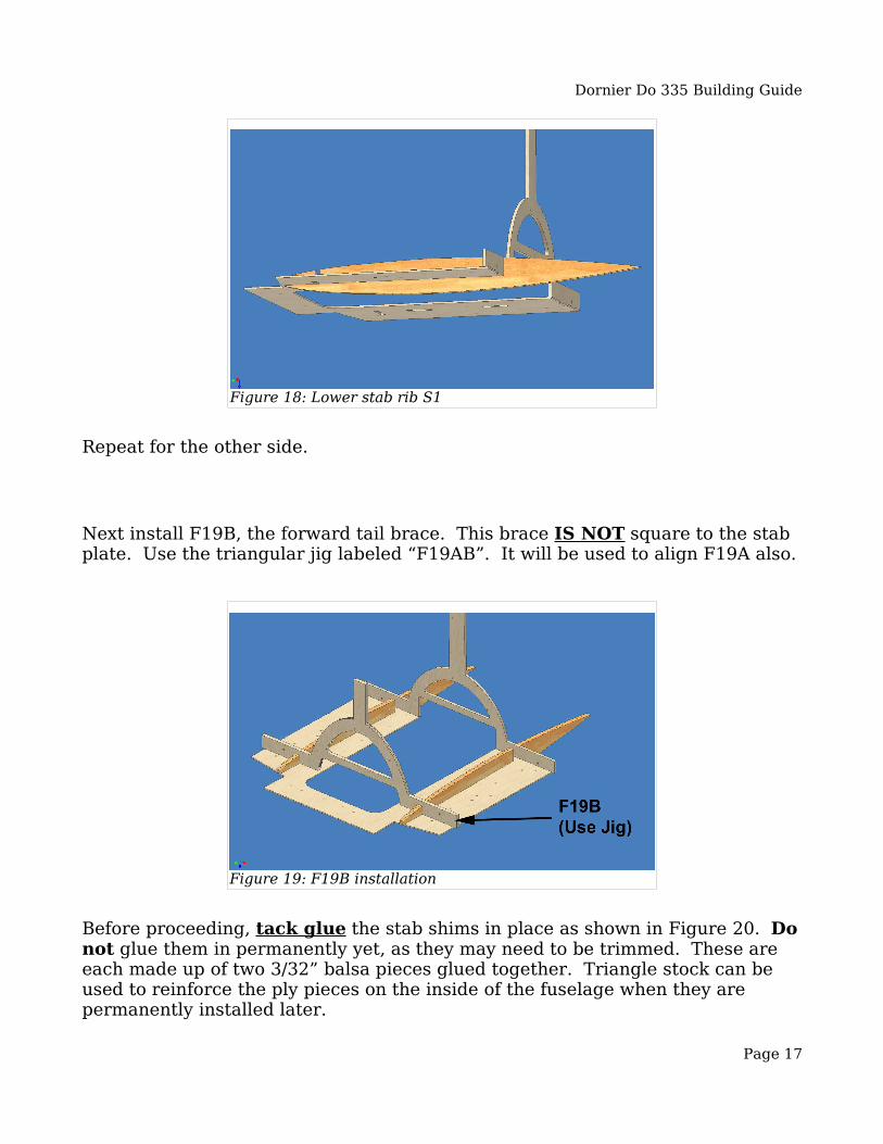
Next glue the lower part of S1 to the bottom of the stab plate. It should also fit into the notch in the stab plate.
Page 16
Figure 17: Upper stab rib S1
Figure 16: Stab base plate and upper tail post
Dornier Do 335 Building Guide
Repeat for the other side.
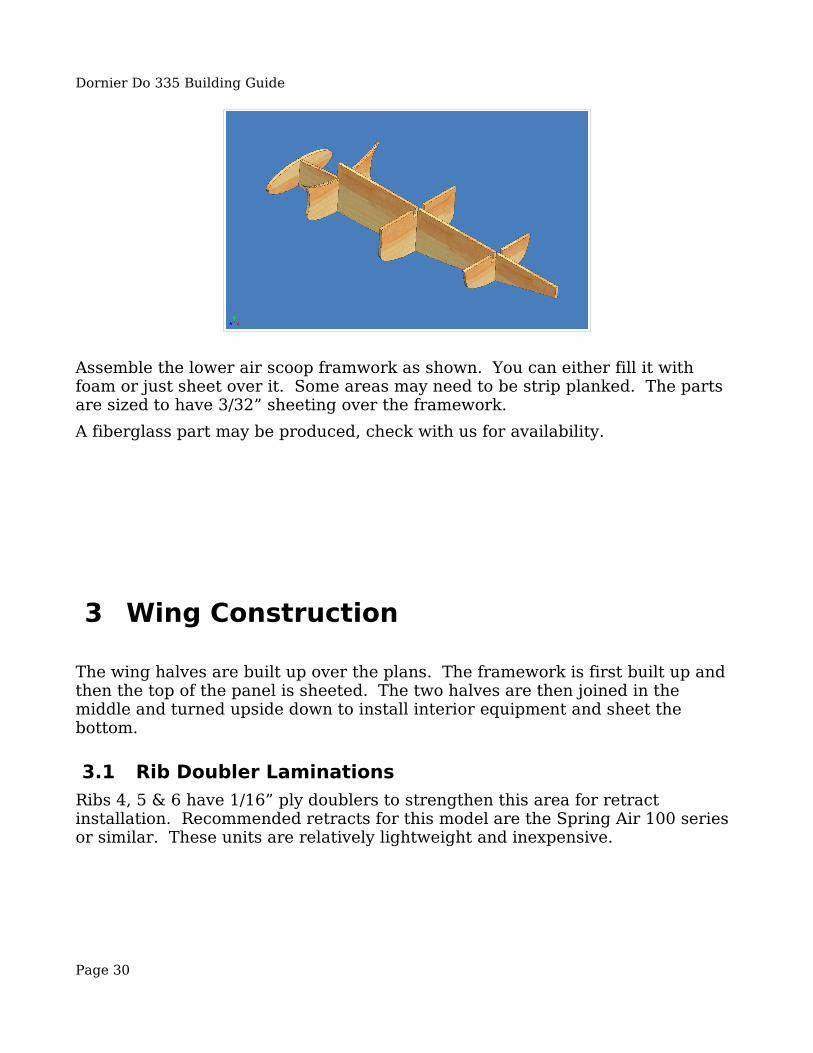
Next install F19B, the forward tail brace. This brace IS NOT square to the stab plate. Use the triangular jig labeled “F19AB”. It will be used to align F19A also.
Before proceeding, tack glue the stab shims in place as shown in Figure 20. Do not glue them in permanently yet, as they may need to be trimmed. These are each made up of two 3/32” balsa pieces glued together. Triangle stock can be used to reinforce the ply pieces on the inside of the fuselage when they are permanently installed later.
Page 17
Figure 18: Lower stab rib S1
Figure 19: F19B installation

Dornier Do 335 Building Guide
Next install F19A. It should be flush with the front of the stab plate. Lay the stab plate in place on the stab shims to make sure F19 and F19A mate properly. Put a piece of waxed paper or Saran Wrap over F19 and under the stab plate. Glue F19A to the stab plate.
Page 18
Figure 21: F19A installation
Figure 20: Installing the stab shims

Dornier Do 335 Building Guide
2.6 Stab ConstructionThe easist way to build the stabs is to build them upside down as shown in Figure 22. You can use balsa sticks or blocks to block up the spar and LE. There should be no twist to the stab, but don't worry about that for now, we'll align them later.
Align the main spar and LE over the plans. Note the position and orientation of the ribs as shown in Figure 22. Align the ribs over the plans and glue in place. When the framework is done, sheet the bottom of the stab with 1/16” balsa. Extend the sheeting past S1 on the plans, you will trim it later.
Page 19
Figure 22: Stab construction
Figure 23: Installing the stab on the stab plate

Dornier Do 335 Building Guide
When the sheeting is dry, glue the stab to the stab plate as shown in . The main stab spar should fit into the slot between S1 and the post. The upper part of the LE will need to be trimmed where shown to clear the stab plate. Repeat for the other side.When the glue on both stabs is dry, install the stab plate on the shims and attach using two screws through the holes in the shims. Check the alignment of the stab. The tips should both be the same distance from the building board.Remove the upper tail from the fuselage. Use a couple of scrap balsa sticks to secure the stab plate to the building board, aligning it parallel to the building surface in both directions. Block up the stab tips so the stab is at zero degrees incidence to the building board (no twist). Sheet the upper half of the stab with 1/16” balsa. Once again extend the sheeting past S1 all the way to the edges of F19A and the tail post.When the stab sheeting is dry on both sides, remove the stab from the building board. Re-attach it to the fuselage and recheck the side-to-side alignment.Next install the upper fin LE as shown in Figure 24. Align it vertically with the upper tail post.
Install the upper fin tip as shown in Figure 25. It is made up of two pieces of 1/4” balsa glued together. The upper tail post should fit into the notch. Using scrap 1/16” balsa, glue ribs between the LE and the post using the plans for reference. Plan your hinge installation and glue in hinge blocks behind the tail post. Sand to airfoil shape and sheet both sides of the upper fin with 1/16” balsa.Place the upper tail on the fuselage and test the fit. F19 should fit tightly against F19A.
Page 20
Figure 24: Installing the upper fin LE

Dornier Do 335 Building Guide
Also at this time, put some Saran wrap or waxed paper over F19 and F20 and sheet the curved part of the upper tail between the fin and stab on both sides using 3/32” balsa. The upper tail is finished!
2.7 Lower Fuselage ConstructionWhen the upper fuselage sheeting is dry and the upper tail is fully aligned, remove the upper fuselage from the building board. You might want to make a cradle or jig to hold the fuselage from this point forward. You will be doing a lot of work inside and out, and a stable base will make all of this work easier.Start by installing the lower fuse braces and FFW (forward firewall). The braces should fit in the notches between the fuse formers and the crutch. See the plans for reference. The front of the braces should be flush with the FFW.
Page 21
Figure 25: Installing the upper fin tip

Dornier Do 335 Building Guide
Note that two different FFW pieces are supplied, only one is to be used. The one with holes is for electric power to cool the batteries. The one with no holes is for glow power. Next install (F10) – (lower F10). The rear of this former should be flush with the flat edge of the brace and also flush with upper F10.
Page 22
Figure 26: Installing the FFW and lower fuse braces
Figure 27: Installation of (F10)

Dornier Do 335 Building Guide
You may want to cut out the retract notch in F5 before you install it. It will be easier now than after it is glued in. Install F5. It fits into slots in the FFW and should be flush with the bottom of the braces.
Next install two F2S formers, (F2), (F3), (F4) and (F8) as shown in Figure 29.
Page 23
Figure 28: Installation of F5
Figure 29: Installing lower formers in the forward fuselage

Dornier Do 335 Building Guide
Install the nosegear well stringers (door frames) as shown in Figure 30. These are from 3/8” x 3/16” balsa. These should be sanded to the fuselage contour on the outside.
Next install lower formers (F11) to (F14). Align these with their upper counterparts and the brace edges. Install (F15) flush with the aft edge of the fuselage brace.
Page 24
Figure 30: Nosegear well stringers
Figure 31: Installing (F11) to (F15)

Dornier Do 335 Building Guide
Also at this time, install the wing hold-down plate as shown in Figure 32 and Figure 33. This is the part that came from the cutout in F10. The rear edge of the plate should align with the front edge of F13. The face of the plate should be flush with the 1/32” ply fuse braces. The plate will rest against the wing in the finished model. See the plans. Reinforce with 1/2” triangle stock on the inside.
Page 25
Figure 32: Wing hold-down plate installation

Dornier Do 335 Building Guide
Install (F16) to (F20). Once again these should be aligned to their upper counterparts.At this point it is advisable to begin installing your elevator and rudder control. There are many options for this. The rudder pushrod can be attached to the lower rudder. A large “U” shaped piece of music wire or a carbon fiber torque
Page 26
Figure 34: Installing (F16) to (F20)
Figure 33: Wing hold-down plate glued in place

Dornier Do 335 Building Guide
rod can be attached to the lower rudder and used to move the upper rudder.Plan your rear engine installation and prepare the aft firewall (AFW). There are two different AFW parts provided, one with holes in it for electric power, another with no holes for glow. Plan your motor installation and glue the AFW to F20.
Begin the lower fin construction by gluing F21 to (F19) and (F20) as shown. It should be centered in the fuse and spaced down 3/32” from the edges of (F19) and (F20) since it will be sheeted over. The lower tail post goes down over F21 and is glued to (F20) also.
The lower fin LE is laminated from three pieces of laser cut 1/8” balsa. Check these parts over the plans to make sure the orientation is correct. The inner
Page 27
Figure 35: Installing F20 on AFW
Figure 36: Lower fin construction

Dornier Do 335 Building Guide
piece is called “TF_LEI”, and the two outer pieces are called “TF_LEO”.
The finished lamination should look like Figure 38.
Install the lower fin LE and tip as shown in Figure 39.
Page 28
Figure 37: Lower fin LE lamination
Figure 38: Finished lower fin LE lamination

Dornier Do 335 Building Guide
As with the upper fin tip, the lower fin tip is made from two laser cut 1/4” balsa pieces glued together to form a 1/2” thick piece.
Install ribs from scrap 1/16” balsa as you did for the upper fin and sand to airfoil shape. Install two pieces of 3/16” sq stick between (F19) and (F20) to reinforce the lower fin. Fill in with scraps and sand flush with (F19) and (F20).
Page 29
Figure 39: Lower fin LE installation
Figure 40: Finished lower fin framework
Dornier Do 335 Building Guide
Assemble the lower air scoop framwork as shown. You can either fill it with foam or just sheet over it. Some areas may need to be strip planked. The parts are sized to have 3/32” sheeting over the framework.A fiberglass part may be produced, check with us for availability.
3 Wing Construction
The wing halves are built up over the plans. The framework is first built up and then the top of the panel is sheeted. The two halves are then joined in the middle and turned upside down to install interior equipment and sheet the bottom.
3.1 Rib Doubler LaminationsRibs 4, 5 & 6 have 1/16” ply doublers to strengthen this area for retract installation. Recommended retracts for this model are the Spring Air 100 series or similar. These units are relatively lightweight and inexpensive.
Page 30

Dornier Do 335 Building Guide
Note that the doublers on ribs 4 and 5 must be glued to the correct side of the rib. See the plans. Make sure you end up with a “left” and “right” set of ribs 4, 5 & 6. Glue the doublers to the ribs with epoxy.The following illustrations show the left wing under construction. You may want to start with the left wing so that your assembly will match the illustrations.
Page 31
Figure 41: Ribs 4,5 & 6 doublers

Dornier Do 335 Building Guide
3.2 Rib 0 and 1 alignment
Use the jig labeled “Rib 0,1 Jig” to align ribs 0 and 1 to the building board. These two ribs are vertical on the finished model, but therefore not square to the building board. The other ribs are angled with the dihedral of the wing, and so they are square to the building board. Align Rib #1 as shown over the plans and secure it to the building board.
Align Rib #0 and secure it to the building board.
Page 32
Figure 42: Rib #1 alignment
Figure 43: Rib #0 alignment (left wing)

Dornier Do 335 Building Guide
Next align Rib #2, it and all remaining ribs are square to the building board.
Page 33
Figure 44: Rib #2 alignment (left wing)
Figure 45: Ribs 3-10 alignment

Dornier Do 335 Building Guide
3.3 Wing Leading Edge InstallationLocate the laser cut wing LE. Glue it in place as shown in Figure 46.
3.4 Spar InstallationThe main spars are laminated from 3/16” x 1/8” balsa sticks. See the rib profiles on the plans for reference. Do the upper main spar first. The first piece goes from Rib 0 to Rib 7. Cut a piece of 3/16” x 1/8” balsa to the proper length and glue it in place as shown in Figure 47.
Page 34
Figure 46: Wing leading edge installation
Figure 47: Laminated main wing spar

Dornier Do 335 Building Guide
The second and third pieces of the main spar go from Rib 0 to a point between ribs 9 and 10. See the plans for reference. They should be trimmed and sanded to merge with the leading edge piece.
Lay a bead of thick CA on the first piece and lay the second piece on top of it, pressing it until the CA grabs.
Do likewise for the third piece. You can also do the lower spar at this time, but it isn't necessary and it will be much easier once the wing is flipped over.Go ahead and sheet the top of the wing panel now. Sand the ribs and spars first, then apply 1/16” sheeting. Leave a 1/4” overlap at the TE. We'll sand this to the contour of the lower surface later. When the sheeting is dry, you can remove the wing from the building board. Repeat for the other wing half.
Page 35
Figure 48: Laminated main spar - 2nd piece
Figure 49: Laminated main spar - 3rd piece
Dornier Do 335 Building Guide
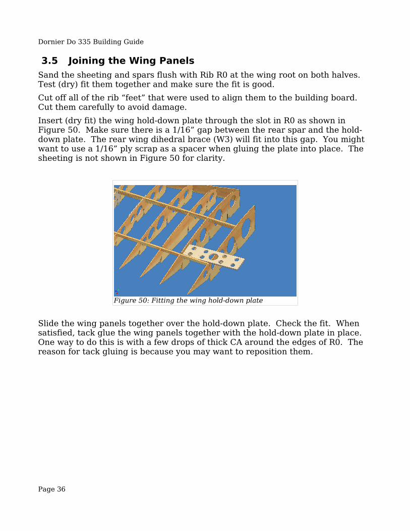
3.5 Joining the Wing PanelsSand the sheeting and spars flush with Rib R0 at the wing root on both halves. Test (dry) fit them together and make sure the fit is good.Cut off all of the rib “feet” that were used to align them to the building board. Cut them carefully to avoid damage.Insert (dry fit) the wing hold-down plate through the slot in R0 as shown in Figure 50. Make sure there is a 1/16” gap between the rear spar and the hold-down plate. The rear wing dihedral brace (W3) will fit into this gap. You might want to use a 1/16” ply scrap as a spacer when gluing the plate into place. The sheeting is not shown in Figure 50 for clarity.
Slide the wing panels together over the hold-down plate. Check the fit. When satisfied, tack glue the wing panels together with the hold-down plate in place. One way to do this is with a few drops of thick CA around the edges of R0. The reason for tack gluing is because you may want to reposition them.
Page 36
Figure 50: Fitting the wing hold-down plate

Dornier Do 335 Building Guide
3.6 Wing Assembly and AlignmentThe wing twist (wash) is not fixed yet. With only the top of the wing sheeted, the panels are still flexible. The purpose of the wing jig is to fix the wing twist to the proper angle before the lower sheeting is applied. Once the lower sheeting is glued in place, the wing twist becomes fixed.The washout of each wing panel is -2 degrees. This means that the incidence of the wingtips is 2 degrees lower than the wing root. This is standard washout and improves low speed handling and stall characteristics.
Align the wing jig over the plans. The middle piece should be centered. The end pieces should be aligned so they're flush with ribs R10. Secure the jig pieces to the building board. Lay the wing in place on the jig and check the alignment. If you glued the root ribs together properly everything should align with minimal movement or pressure to make the wing sit in the jig. If the alignment isn't right, you can cut ribs R0 apart and re-position them. When you're satisfied with the alignment, glue ribs R0 permanently together.Now position the wing hold-down plate so that it is square to both ribs R1. Use a small square to ensure this. When satisfied, glue it permanently using epoxy. Check the 1/16” gap between it and the rear spar one more time before the glue sets.Tack glue (or otherwise secure) the wing to the wing jig. It is important that the jig and wing are firmly secured, because you will be sanding and otherwise pushing and pulling on the wing and it should not break free. Just remember that you will have to take it apart later, so don't glue it too well.
Page 37
Figure 51: Wing jig placement

Dornier Do 335 Building Guide
3.7 Wing Dihedral BracesGlue the front dihedral brace into the slots in ribs R0, R1 & R2. Use epoxy for all of the dihedral braces. Reinforce this brace with 3/8” triangle stock at ribs R1 and R2 as shown on the plans. This brace mates with (F10) so install it carefully and make sure it is centered.
Next glue the main dihedral brace into the slots next to the main spar.
Page 38
Figure 52: Front wing dihedral brace installation
Figure 53: Center wing dihedral brace installation
Dornier Do 335 Building Guide
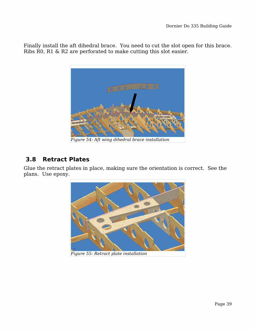
Finally install the aft dihedral brace. You need to cut the slot open for this brace. Ribs R0, R1 & R2 are perforated to make cutting this slot easier.
3.8 Retract PlatesGlue the retract plates in place, making sure the orientation is correct. See the plans. Use epoxy.
Page 39
Figure 55: Retract plate installation
Figure 54: Aft wing dihedral brace installation
Dornier Do 335 Building Guide
3.9 Finishing the lower wingAt this time you should perform the following steps before sheeting the lower wings. See the plans for details.
● Install the lower spars, main spars and sub-spars (aileron & flap area).● Install shear webbing on the front of the main spars.● Install conduits for the aileron servo leads.● Glue in hinge blocks for the ailerons if needed.● Install retract units and air lines.● Install wheel well sheeting.
When all this is done, sheet the lower wing with 1/16” balsa. Leave the area between the main dihedral brace, the front dihedral brace and ribs R1 so that the wing hold-down dowels can be installed.When the lower sheeting is dry, you can remove the wing from the jig.
3.10 Aligning and Finishing the WingThe wing leading edges are tapered and sharpened near the root. Make them up from 3/8” sticks shown in the BOM. Sand them flush with ribs R1, but don't shape them yet. Fit the wing to the fuselage and see that the front dihedral brace and (F10) mate properly. Check the alignment of the wing to the fins and stab on the fuse. Sand/shim the wing saddle area as required to get the proper alignment. When satisfied, drill holes for the wing dowels through (F10) and the front dihedral brace. Glue in the 1/2” triangle stock wing dowel reinforcement and drill through. Install the wing dowels in the front dihedral brace with epoxy.Check that the wing is aligned side to side by measuring from the nose or tail to each wingtip. Sand or shim (F10) as necessary. When satisfied, drill two holes through the wing hold-down blocks to accept 1/4-20 nylon screws. The fuselage side should be tapped with a 1/4-20 tap.You can now finish and shape the wing and fuse mating area. Construct the belly pan and ventral scoop using the framework parts provided. Make wing fillets using the 1/64” ply parts provided, fill them with epoxy/microballoons or similar material.Glue the wingtip blocks together and shape. You can hollow these out to save weight.
Page 40
Dornier Do 335 Building Guide
4 Finishing 4.1 Finishing MethodsIf you're using electric power, weight will be more important than if you use glow power. It is therefore recommended that you consider your finishing methods carefully. The smoother the surface is before finishing, the lighter the finish will be. The following layers are heavier. Cover with a very light (½ or ¾ oz) fiberglass cloth. Instead of the traditional epoxy and primer finish, I recommend the following to reduce weight. Use nitrate dope instead of epoxy. Lay down the cloth over the surface and trim. Apply a generous coat of dope and allow it to soak through the cloth into the wood. When dry, lightly sand and apply a second generous coat of dope. When that is dry, lightly sand again and mix up a small batch of dope mixed with microballoons to a ketchup-like consistency. Apply this in a thick coat over the cloth. This coat should fill the weave of the cloth. When dry, sand smooth using successively finer sandpaper and a sanding block. Start with 200 grit and work down to 400. Any paint should be useable over that. It's advisable to try a test piece to make sure your paint is compatible. Some have used water based polyurethane instead of nitrate dope. A coat of nitrate dope is still used first to seal the bare wood. We have not tried this method but others swear by it.
4.2 Paint & MarkingsMany different paints can be used. Since this is an electric model and fuel proofing is not required, you might consider using paint for plastic models as these come in very accurate colors and are readily available in any well stocked hobby shop. The Do 335 was painted in a splinter pattern of RLM 81 Dunkelgruen and RLM 82 Lichtgruen upper surfaces and RLM 76 lower surfaces.For markings, you can use whatever stick-on markings you can find, but they won't be accurate. I encourage you to use the marking templates supplied. It's a little more work this way, but the results are worth it.You can just cut these out and use them as masks directly. Just tape and hold them down on the wing/fuse and spray the markings on. If you're careful, you'll only get a little over spray which won't be noticeable from a distance. If you want cleaner lines, a good way to use these is to use 3M 77 spray adhesive to glue the templates to frisket paper or other adhesive backed paper with a low-tack adhesive. 3M 77 leaves a residue, so it is not recommended to use it to attach anything directly to the model. You can then cut through the outlines of the Balkankreuz and Hakenkreuz which will yield easy to use (and reusable) paint masks.
Page 41

Dornier Do 335 Building Guide
5 Trimming for Flight 5.1 Center of GravityBalance the model to the CG shown on the plans.It is best to start out with a CG 1/16” - 1/8” forward of that shown on the plans. Be sure to also balance the model laterally. If you have built the model according to plan and your equipment installation is more or less symmetrical, you should not need much lead in the wing tips. If you're putting more than an ounce or two, there is probably something wrong with your balancing method!
5.2 Balancing MethodDo not attempt to balance the model by suspending it from a rope. This method is not reliable. Use a carpenter's square or similar to measure the CG location. Mark the CG location on the top of the wing on either side of the fuse. Hold the model upside down with your thumbs on the CG lines. It is also possible to use one of the commercially available balancing jigs, such as the one from Great Planes (CG Machine).Move the internal equipment or ballast the model until the correct fore/aft CG is established. It is best to start with it a bit nose heavy and gradually shift the CG aft. Don't go too far nose heavy though, as the model doesn't fly well if it is drastically nose heavy. You will struggle to keep the nose up and it will “mush” instead of “fly”.
5.3 Recommended Control ThrowsFor the first flights, start with 1/4-3/8” throw on the ailerons, 3/16-1/4” on the elevators. You can experiment with varying these to taste. You can adjust the rudders to maximum throw, anything up to about 30-45 degrees is fine.
5.4 Power SetupThe prototype model was flown with two Eflite Power 46 brushless outrunner motors, two 80 Amp Scs and two 4S 5000 mAh Li-Poly battery packs. This yielded flight times in the 5-7 minute range. Your results may vary depending on model weight, flying style, etc. Smaller battery packs could be used.
Page 42

Dornier Do 335 Building Guide
6 Flying the Do 335 6.1 General Flying CharacteristicsIn general, the Do 335 handles much like any other plane. The weight of the motor and the gyroscopic effect of the rear propellor produce flying qualities that are quite unique. The Do 335 is very stable, both on the ground and in the air. If you keep the weight down, you will find it very easy and pleasant to fly.
6.2 AerobaticsThe Do 335 is capable of all the standard aerobatics. Stall turns are a bit weird because of the weight distribution.
6.3 Ground “sit”The model should have a little (2-3 degrees) positive incidence while at rest on the ground. If the nose is too low, the model will not want to rotate and a long takeoff roll will result.
6.4 More Info
6.4.1 RCSB ThreadGo to http://www.rcscalebuilder.com and register. It's free and worth your trouble. Trust me. The 60” Do 335 thread is in the “Other Designers” forum.
6.4.2 Yahoo Group “Do335”Go to http://groups.yahoo.com/group/do335/ and join the group. This is a good place to post questions and connect with others building the Do 335. The building guides are also posted here in PDF format.
6.4.3 Phone and “Snail Mail”Finally, if you don't have Internet access and need help, feel free to contact us by letter or phone. The address and phone number are listed on the title page of this building guide.
Page 43