Embed Size (px)
Citation preview
Doosan Infracore Porta ble Power
OLTFP Ingersoll Rand LIGHTSOURCE V9
OPERATION AND MAINTENANCE MANUAL
SERIAL No : 368000 -> This manual contains important safety information and must be made available to personnel who operate and maintain this machine.
C.C.N. : 46500039 en REV : A DATE DECEMBER 2008
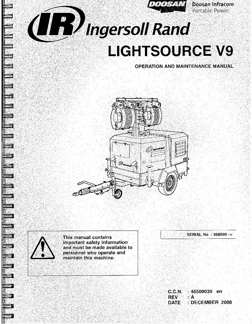
DECLARATION OF CONFORMITY WITH EC DIRECTIVES
28625-9218
Doosan International USA, Inc 1293 Glenway Drive Statesville, North Carolina
93/68/EEC, 2004/108/EC, 2000/14/EC
We Doosan Trading Limited
Represented in EC by: 170-175 Lakeview Drive Airside Business Park Swords County Dublin Ireland
responsibility for manufacture and supply, the product(s)
LIGHTSOURCE V9 declaration relates, is (are) in conformity with the provisions of the above
directives using the following principal standards
Ric Lunsford Manager of quality control
EN29001, EN60204-1
IVIcItA III IC I I IOUCIS I Cpi CJCI Ileu II I WIlS I I Ictl IUctl I I lely U USCU II I VctI IUUS IUUdLIUIIS WUFIU — WIUe. IvIdur lIr les SUIU dUO Sf lIppeU
into European Union Territories require that the machine display the EC Mark and conform to various directives. ln such cases, the design specification of this machine has been certified as complying with EC directives. Any modification to any part is absolutely prohibited and would result in the CE Certification and marking being rendered invalid. A declaration of that conformity follows:
CE
CONFORMITY WITH NOISE DIRECTIVE 2000/14/EC Doosan International USA Inc declare that the following Portable Compressors have been manufactured in
conformity with the directive as shown
Directive machine
Type kW S erial number
range Mean measured
value Guaranteed
Level Notified body
2000/14/EC Annex VI
Part l V9 8.4 368000 -> 87 LWA 88 LWA
A V Technology Stockport UK
Nr 1067
Issued at Dobris Tomasl-libs SEPTEMBER 2008 Engineering manager
EC Pressure Equipment Directive and Related Regulations
We declare that this product has been assessed according to the Pressure Equipment Directive (97/23/EC) and in accordance with the terms of this Directive, has been excluded from the scope of this Directive. lt may carry "CE" marking in compliance with other applicable EC Directives.
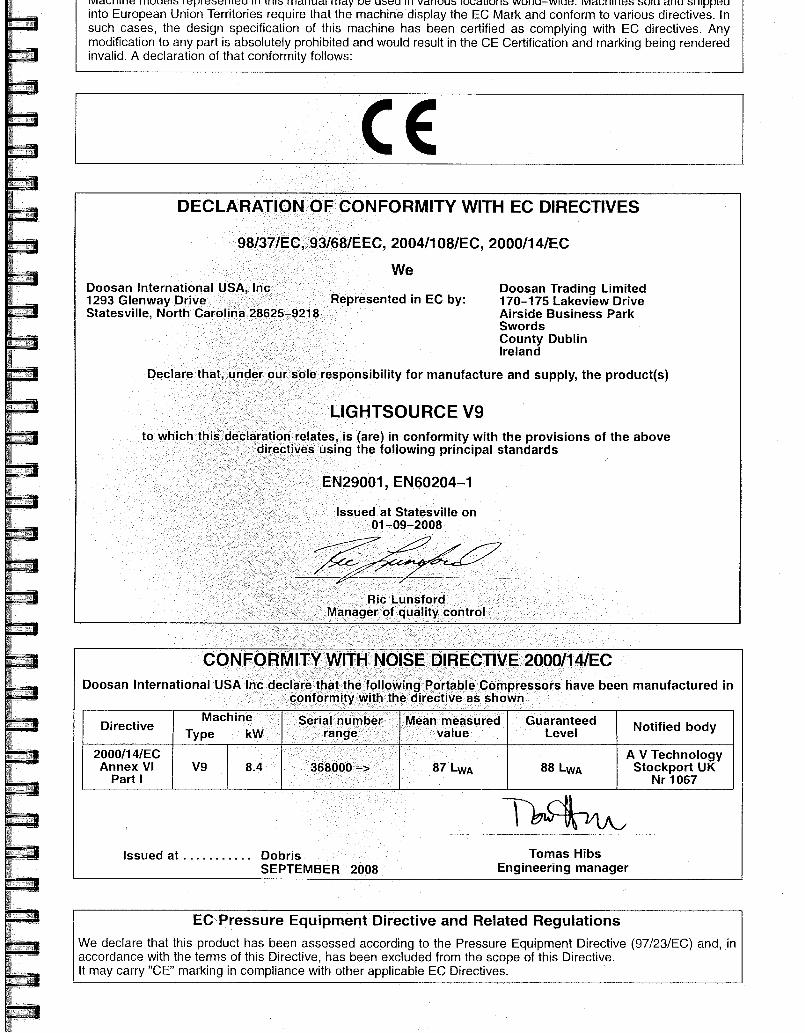
1 CONTENTS ABBREVIATIONS & SYMBOLS
2 FOREWORD #### Contact IngersoH Rand for serial number
->#### Up to Serial No. 3 WARRANTY ####-> From Serial No.
9 DECALS
SAFETY
GENERAL INFORMATION
OPERATING INSTRUCTIONS
Not illustrated
Option
AR
As required
HA High ambient machine
EH.R.G. Fixed height running gear
V.H.R.G. Variable height running gear
bg Bulgarian cs Czech da Danish de German el Greek en English es Spanish et Estonian fi Finnish fr French hu Hungarian it Italian It Lithuanian Iv Latvian, Lettish mt Maltese n1 Dutch no Norwegian pi Polish pt Portuguese ro Romanian ru Russian sk Slovak sl Slovenian sv Swedish zh Chinese
12
17
19
24 MAINTENANCE
32 MACHINE SYSTEMS
39 FAULT FINDING
41 ENGINE INSTRUCTION MANUAL
LIGHTSOURCE V9
FOREWORD
The contents of this manual are considered to be proprietary and confidential to Ingersoll Rand and should not be reproduced without the prior written permission of Ingersoll Rand.
Nothing contained in this document is intended to extend any promise, warranty or representation, expressed or implied, regarding the Ingersoll Rand products described herein. Any such warranties or other terms and conditions of sale of products shall be in accordance with the standard terms and conditions of sale for such products, which are available upon request.
This manual contains instructions and technical data to cover all routine operation and scheduled maintenance tasks by operation and maintenance staff. Major overhauls are outside the scope of this manual and should be referred to an authorised Ingersoll Rand service department.
The design specification of this mach ne has been certified as complying with EC directives. As a result:
(a) Any machine modifications are strictly prohibited, and will invalidate EC certification.
(b) A unique specification for USA/Canada is adopted and tailored to the territory.
All components, accessories, pipes and connectors added to the machine should be: . of good quality, procured from a reputable manufacturer and, wherever possible, be of a type approved by Ingersoll Rand.
accompanied with instructions for safe installation, operation and maintenance.
Details of approved equipment are available from Ingersoll Rand Service departments.
The use of repair parts / lubricants / fluids other than those included within the Ingersoll Rand approved parts list may create hazardous conditions over which Ingersoll Rand has no control. Therefore Ingersoll Rand cannot be held responsible for equipment in which non-approvedrepair parts are installed.
Ingersoll Rand reserves the right to make changes and improvements to products without notice and without incurring any obligation to make such changes or add such improvements to products sold previously.
The intended uses of this machine are outlined below and examples of unapproved usage are also given, however Ingersoll Rand cannot anticipate every application or work situation that may arise.
IF IN DOUBT CONSULT SUPERVISION.
The use of the machine in any of the situation types listed in table 1:- a) Is not approved by Ingersoll Rand, b) May impair the safety of users and other persons, and c) May prejudice any claims made against Ingersoll Rand.
TABLE 1
Use of the machine outside the ambient ternperature range
specified in the GENERAL INFORMATION SECTION of this manual.
This machine is not intended and must not be used in potentially explosive atmospheres, including situations where flammable gases or vapours may be present.
Use of the machine fitted with non Ingersoll Rand approved components / lubricants / fluids.
Use of the machine with safety or control components missing or
disabled.
Use of the machine for storage or transportation of materials inside or on the enclosure except when contained within the toolbox.
GENERATOR
Use of the generator to supply load(s) greater than those specified.
Use of unsafe or unserviceable electrical equipment connected to
the generator.
Use of electrical equipment: (a) Having incorrect voltage and/or frequency ratings.
(b) Containing computer equipment and/or similar electronics.
The company accepts no responsibility for errors in translation of this manual from the original English version.
COPYRIGHT 2008
DOOSAN COMPANY
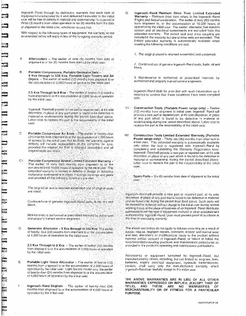
A. Aftercoolers - The earlier of nine (9) months from date of shipment to or six (6) months from start up by initial user.
8. Portable Compressors, Portable Generator Sets - 9 Kva through to 550 Kva, Portable Light Towers and Air Dryers - The earlier of twelve (12) months from shipment to or the accumulation of 2,000 hours of service by the initial user.
authorized
2.5 Kva Through to 8 Kva - The earlier of twelve (12) months from shipment to or the accumulation of 2,000 hours of operation by the initial user.
Ingersoll-Rand, through its distributor, warrants that each item of equipment manufactured by it and delivered hereunder to the initial user will be free of defects in material and workrnanship for a period of three (3) months from initial operation or six (6) months from the date of shipment to the initial user, whichever occurs first.
With respect to the following types of equipment, the warranty period enumerated below will apply in lieu of the foregoing warranty period.
Ingersoll-Rand Platinum Drive Train Limited Extended Warranty Platinum drive train refers to the Ingersoll-Rand Engine and Airend combination. The earlier of sixty (60) months from shipment to, or the accumulation of 10,000 hours of operation by the initial user. The starter, alternator, fuel injection system and all electrical components are excluded from this extended warranty. The airend seal and drive coupling are included in the warranty but airend drive belts are excluded. This limited extended warranty is automatically available when meeting the following conditions are met:
1. The original airend is returned assembled and unopened.
2. Continued use of genuine Ingersoll-Rand parts, fluids, oil and filters.
3. Maintenance is performed at prescribed intervals by authorized and properly trained service engineers.
2.5 Kva Through to 8 Kva - The earlier of twelve (12) months from shipment to or the accumulation of 2,000 hours of operation by the initial user.
Ingersoll-Randwill provide a new part or repaired part, at it's sole discretion, in place of any part which is found 10 be defective in material or workmanship during the period described above. Labor cost to replace the part is the responsibility of the initial user
C. Portable Compressor Air Ends - The earlier of twenty-four (24) months from shipment to or the accumulation of 4,000 hours of service by the initial us For Air Ends, the warranty against defects will include replea rCement of the complete Air En d provided the original Air End is returned assembled ndall
a o riginal seals are intact.
Cl . Portable Compressor Airend Limited Extended Warranty - The earlier of sixty (60) months from shipment to or the accumulation of 10,000 hours of operation by the initial user. Th extended warrantY is limited to defects in design or defe is ctive material or workmanship in rotors, housings, bearings and gears and provided all the following conditions are met:
The original air end is returned assembled are intact.
Ingersoll-Rand shall be provided with such information as it requires to confirm that these conditions have been complied with.
H1. Construction Tools, (Portable Power range only) Twelve (12) months from shipment to initial user. Ingersoll-Rand will provide a new part or repaired part, at it's sole discretion, in place of any part which is found to be defective in material or workmanship during the period described above. Labor cost to replace the part is the responsibility of the initial user.
H2. Construction Tools Limited Extended Warranty, (Portable Power range only) - Thirty-six (36) months from shipment to initial user. This extended warranty is automatically available only when the tool is registered with Ingersoll-Rand by completing and submitting the Warranty Registration form. Ingersoll-Randwill provide a new part or repaired part, at it's sole discretion, in place of any part which is found to be defective in material or workmanship during the period described above. Labor cost to replace the part is the responsibility of the initial user.
s Six (6) months from date of shipment to the initial
Continued use of genuine Inge filters.
Maintenance is performed at prescribed intervals and properly trained service engineers.
Ingersoll-Rand will provide a new part or repaired part, at its sole discretion in place of any part that is found to be defective in material and workmanship during the period described above. Such parts will be repaired or replaced without charge to the initial user during normal working hours at the place of business of an Ingersoll-Rand distributor authorized to sell the type of equipment involved or other establishment authorized by Ingersoll-Rand. User must present proof of purchase at the time of exercising warranty.
D. Generator Alternator - 9 Kva through to 550 Kva. The earlier of twenty-four (24) months from shipment to or the accumulation of 4,000 hours of operation by the initial user.
Portable Light Tower Alternator - The earlier of twelve (12) months from shipment to or the accumulation of 2,000 hours of operation by the initial user. Light Source model only, the earlier of twenty-four (24) months from shipment to or the accumulation of 4,000 hours of operation by the initial user.
Ingersoll-Rand Engines - The earlier of twenty-four (24) months from shipment to or the accumulation of 4,000 hours of operation by the initial user.
The above warranties do not apply to failures occurring as a result of abuse; misuse, negligent repairs, corrosion, erosion and normal wear and tear, alterations or modifications made to the product without express written consent of Ingersoll-Rand; or failure to follow the recommended operating practices and maintenance procedures as provided in the product's operating and maintenance publications.
Accessories or equipment furnished by Ingersoll-Rand, but manufactured by others, including, but not limited to, engines, tires, batteries, engine electrical equipment, hydraulic transmissions, carriers, shall carry only the manufacturers warranty, which Ingersoll-Rand can lawfully assign to the initial user.
THE ABOVE WARRANTIES ARE IN LIEU OF ALL OTHER WARRANTIES EXPRESSED OR IMPLIED, (EXCEPT THAT OF TITLE), AND THERE ARE NO WARRANTIES OF MERCHANTABILITY OR OF FITNESS FOR A PARTICULAR PURPOSE.
LIGHTSOURCE V9
WARRANTY
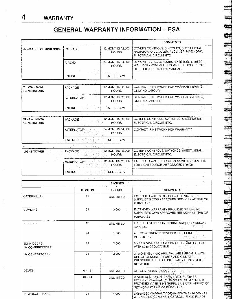
GENERAL WARRANTY INFORMATION - ESA
COMMENTS
PORTABLE COMPRESSOR PACKAGE 12 MONTHS / 2,000 HOURS
COVERS CONTROLS, SWITCHES, SHEET METAL, RADIATOR, OIL COOLER, RECEIVER, PIPEWORK, ELECTRICAL CIRCUIT ETC.
AIREND 24 MONTHS / 4,000 HOURS
60 MONTHS / 10,000 HOURS. EXTENDED LIMITED WARRANTY AVAILABLE ON MAJOR COMPONENTS. REFER TO OPERATOR'S MANUAL
ENGINE SEE BELOW
2.5kVA - 8kVA GENERATORS
PACKAGE 12 MONTHS / 2,000 HOURS
CONTACT IR NETWORK FOR WARRANTY (PARTS ONLY NO LABOUR).
ALTERNATOR 12 MONTHS / 2,000 HOURS
CONTACT IR NETWORK FOR WARRANTY (PARTS ONLY NO LABOUR).
ENGINE SEE BELOW
9kVA - 550kVA GENERATORS
PACKAGE 12 MONTHS / 2,000 HOURS
COVERS CONTROLS, SWITCHES, SHEET METAL, ELECTRICAL CIRCUIT ETC.
ALTERNATOR 24 MONTHS / 4,000 HOURS
CONTACT IR NETWORK FOR WARRANTY.
ENGINE SEE BELOW
LIGHT TOWER PACKAGE 12 MONTHS / 2,000 HOURS
COVERS CONTROLS, SWITCHES, SHEET METAL, ELECTRICAL CIRCUIT ETC
ALTERNATOR 12 MONTHS / 2,000 HOURS
EXTENDED WARRANTY OF 24 MONTHS / 4,000 HRS FOR LIGHTSOURCE INTRODUCED 8/16/99
ENGINE SEE BELOW
ENGINES
MONTHS HOURS COMMENTS
CATERPILLAR 12 UNLIMITED EXTENDED WARRANTY PROVIDED VIA ENGINE SUPPLIER'S OWN APPROVED NETWORK AT TIME OF PURCHASE.
CUMMINS 24 2,000 EXTENDED WARRANTY PROVIDED VIA ENGINE SUPPLIER'S OWN APPROVED NETWORK AT TIME OF PURCHASE.
PERKINS 12 UNLIMITED IF UNDER 500 HOURS IN FIRST YEAR THEN BELOW APPLIES.
24 1,000 ALL COMPONENTS COVERED EXCLUDING INJECTORS.
JOHN DEERE (IN COMPRESSORS)
(IN GENERATORS)
24 2,000 5 YRS/5,000 HRS USING OEM FLUIDS AND FILTERS WITH $250 DEDUCTABLE
24 2,000 24 MONTHS / 4,000 HRS. AVAILABLE FROM IR WITH USE OF GENUINE IR PARTS AND OILS AT PRESCRIBED SERVICE INTERVALS. CONTACT IR NETWORK.
DEUTZ 0 - 12 UNLIMITED ALL COMPONENTS COVERED.
13 - 24 UNLIMITED MAJOR COMPONENTS COVERED. FURTHER EXTENDED WARRANTY ON MAJOR COMPONENTS PROVIDED VIA ENGINE SUPPLIER'S OWN APPROVED NETWORK AT TIME OF PURCHASE.
INGERSOLL-RAND 24 4,000 EXTENDED WARRANTY OF 60 MONTHS / 10,000 HRS. WHEN USING GENUINE INGERSOLL-RAND FLUIDS
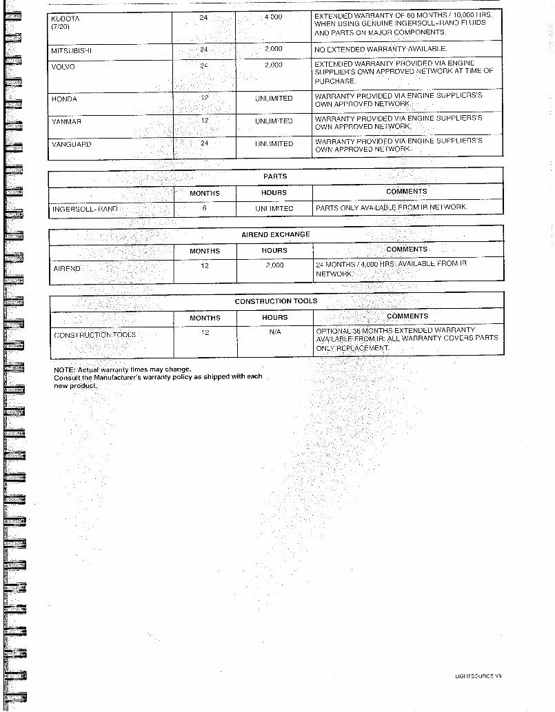
NOTE: Actual warranty times may change. Consult the Manufacturer's warranty policy as shipped with each new product.
KUBOTA (7/20)
24 4,000 EXTENDED WARRANTY OF 60 MONTHS / 10,000 HRS WHEN USING GENUINE INGERSOLL-RAND FLUIDS AND PARTS ON MAJOR COMPONENTS
MITSUBISHI 24 2,000 NO EXTENDED WARRANTY AVAILABLE
VOLVO 24 2,000 EXTENDED WARRANTY PROVIDED VIA ENGINE SUPPLIER'S OWN APPROVED NETWORK AT TIME OF PURCHASE
HONDA 12 UNLIMITED WARRANTY PROVIDED VIA ENGINE SUPPLIERS'S OWN APPROVED NETWORK.
YANMAR 12 UNLIMITED WARRANTY PROVIDED VIA ENGINE SUPPLIERS'S OWN APPROVED NETWORK.
VANGUARD 24 UNLIMITED WARRANTY PROVIDED VIA ENGINE SUPPLIERS'S OWN APPROVED NETWORK
PARTS
MONTHS HOURS COMMENTS
INGERSOLL-RAND 6 UNLIMITED PARTS ONLY AVAILABLE FROM IR NETWORK.
AIREND EXCHANGE
MONTHS HOURS COMMENTS
AIREND 12 2000. 24 MONTHS / 4,000 HRS. AVAILABLE FROM IR NETWORK.
CONSTRUCTION TOOLS
MONTHS HOURS COMMENTS
CONSTRUCTION TOOLS 12 N/A OPTIONAL 36 MONTHS EXTENDED WARRANTY AVAILABLE FROM IR. ALL WARRANTY COVERS PARTS ONLY REPLACEMENT
LIGHTSOURCE V9
1 XHP650/900/1070/1170 will continue o use XHP505 and will have the extended warran y when above conditions a e me
Pro-Tec ' m and XI-IP505 Compressor Fluids are available from your local Ingersoll-Rand branch or distributor.
For units operating within the USA & Canada, call the Mocksville Product Support Department on 1-800-633-5206
6 WARRANTY
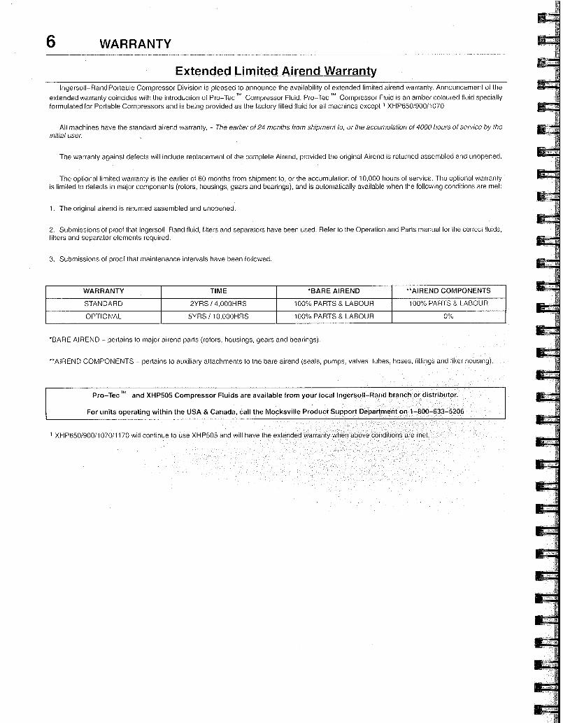
Extended Limited Airend Warranty Ingersoll-Rand Portable Compressor Division is pleased to announce the availability of extended limited airend warranty. Announcement of the
extended warranty coincides with the introduction of Pro-Tec Compressor Fluid. Pro-Tec Compressor Fluid is an amber coloured fluid specially formulated for Portable Compressors and is being provided as the factory filled fluid for all machines except 1 XHP650/900/1070
All machines have the standard airend warranty, - The earlier of 24 months from shipment to, or the accumulation of 4000 hours of service by the initial user.
The warranty against defects will include replacement of the complete Airend, provided the original Airend is returned assembled and unopened.
The optional limited warranty is the earlier of 60 months from shipment to, or the accumulation of 10,000 hours of service. The optional warranty is limited to defects in major components (rotors, housings, gears and bearings), and is automatically available when the following conditions are met:
1. The original airend is returned assembled and unopened.
2. Submissions of proof that Ingersoll-Rand fluid, filters and separators have been used. Refer to the Operation and Parts manual for the correct fluids, filters and separator elements required.
3. Submissions of proof that maintenance intervals have been followed.
WARRANTY TIME *BARE AIREND **AIREND COMPONENTS
STANDARD 2YRS / 4,000HRS 100% PARTS & LABOUR 100% PARTS & LABOUR
OPTIONAL 5YRS / 10,000HR5 100% PARTS & LABOUR 0%
'BARE AIREND - pertains to major airend parts (rotors, housings, gears and bearings).
-AIREND COMPONENTS - pertains to auxiliary attachments to the bare airend (seals, pumps, valves, tubes, hoses, fittings and filter housing).
proof of the "in service date when requesting engine warran y repairs You MUST provide
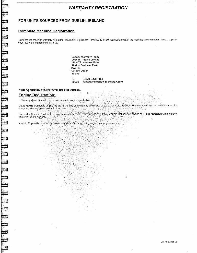
WARRANTY REGISTRATION
FOR UNITS SOURCED FROM DUBLIN, IRELAND
Complete Machine Registration
To initiate the machine warranty, fill out the "Warranty Registration" form 83242 11/99 supplied as part of the machine documentation, keep a copy for your records and mail the original to:
Doosan Warranty Team Doosan Trading Limited 170-175 Lakeview Drive Airside Business Park Swords County Dublin ireland
Fax: (+353) 1 870 7404 Email: [email protected]
Note: Completion of this form validates the warranty.
Engine Registration: I-R powered machines do not require separate engine registration
Deutz require a separate engine registration form to be completed and mailed documentation for Deutz powered machines
The form is supplied as part of the machine
Caterpillar, Cummins and Perkins dealer to initiate warranty.
do not require a separa e registration form but they s ipula e that any new engine should be registered with their local
LIGHTSOURCE V9
rial naber :
Post / Zip Code :
Country :
Phone Number :
Fax Number :
e-mail :
Alternator Serial Number
Ai end Se ial Number :
Da e of start up
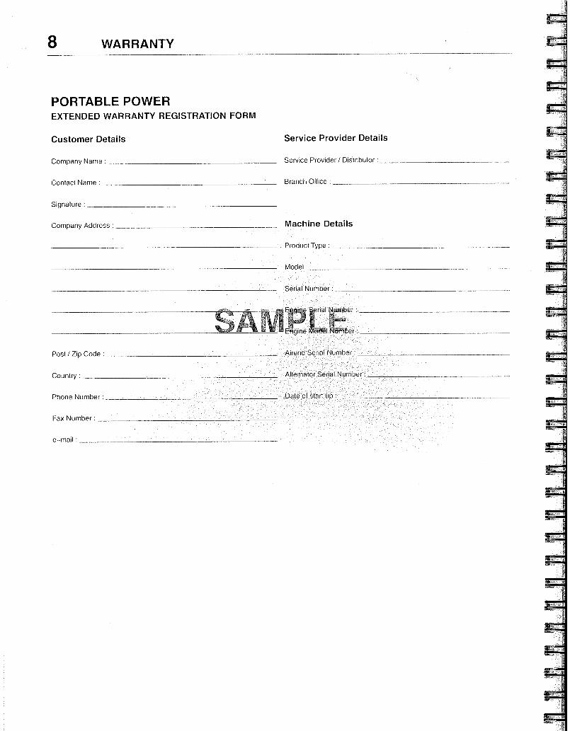
8 WARRANTY
PORTABLE POWER EXTENDED WARRANTY REGISTRATION FORIVI
Customer Details Service Provider Details
Company Name : Service Provider / Distributor :
Contact Name : Branch Office :
Signature :
Company Address : Machine Details
Product Type
Model
Ellgine Mb-dël riltqffiber :
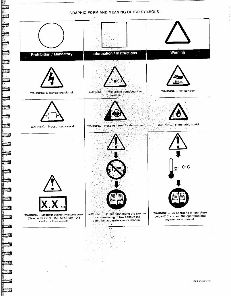
Prohibition / Mandatory Information / Instructions
GRAPHIC FORM AND MEANING OF ISO SYMBOLS
WARNING: risk
11).(li
/3110 is IM,M,.
WARNING - Hot surface. Electrical shock WARNING - Pressurised component or
system.
WARNING
..D.'
WARNING - Hot and harmful exhaust gas. WARNING Flammable liquid. - Pressurised vessel.
WARNING (Refer to
pressure.
' 41_10:.411■ fi
sivi WARNING - Before connecting the tow bar
or commencing to tow consult the operation and maintenance manual.
fl....‘4"› 0 ° C
EIS WARNING - For operating temperature below 0°C, consult the operation and
maintenance manual.
x xBAR
- Maintain correct tyre the GENERAL INFORMATION section of this manual)
LIGHTSOURCE V9
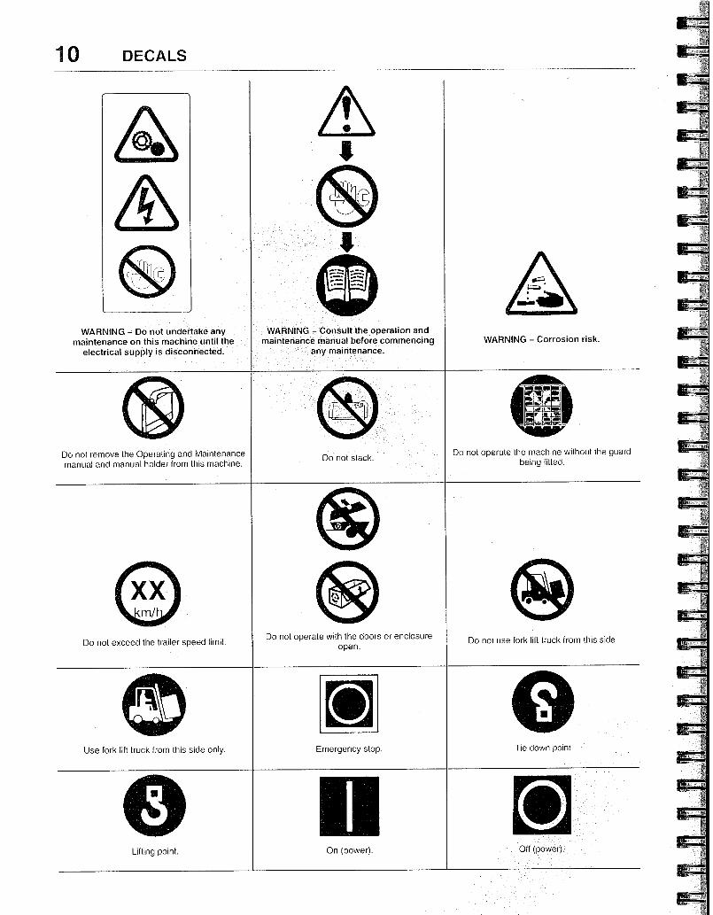
WARNING - Do not undertake any maintenance on this machine until the
electrical supply is disconnected.
Do not remove the Operating and Maintenance manual and manual holder from this machine.
WARNING - Consult the operation and maintenance manual before commencing
any maintenance.
Emergency stop. Use fork lift truck from this side only.
On (power). Lifting point.
Tie down po nt
10 DECALS
WARNING - Corrosion risk.
Do not operate the machine without the guard being fitted.
Do not exceed the trailer speed limit. Do not operate with the doors or enclosure
open. Do not use fork lift truck from this side.
§
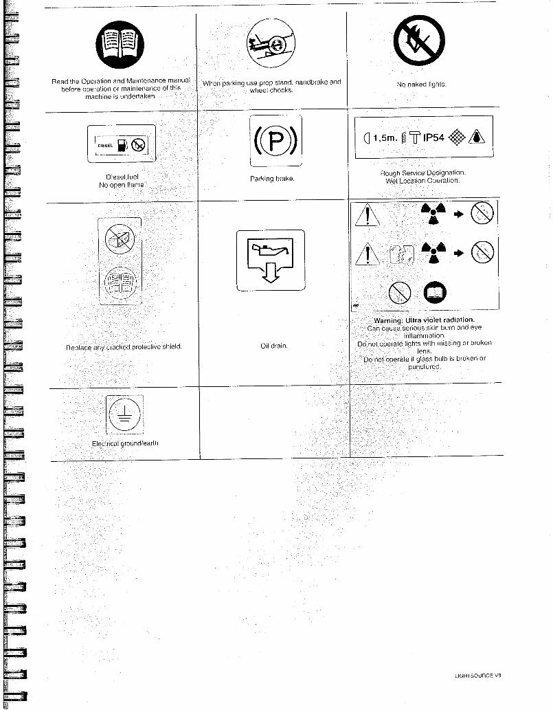
Read the Operation and Maintenance manual before operation or maintenance of this
machine is undertaken.
* e
When parking use prop stand, handbrake and wheel chocks.
No naked lights.
1,5m. 0 U IIP54 "
Rough Service Designation. Wet Location Operation. Diesel fuel
No open flame Parking brake.
04ti tii, r
1
J. L
. _. 1
g■ 41 e Ob
t), 1 wil
Oil drain. Replace any c acked protective shield.
Warning: Ultra violet radiatiort Can cause serious skin burn and eye
inflammation. Do not operate lights with missing or broken
lens. Do not oPerate if glass bulb is broken or
punctured.
Electrical
1, --J
ground/earth
LIGHTSOURCE V9
12 SAFETY
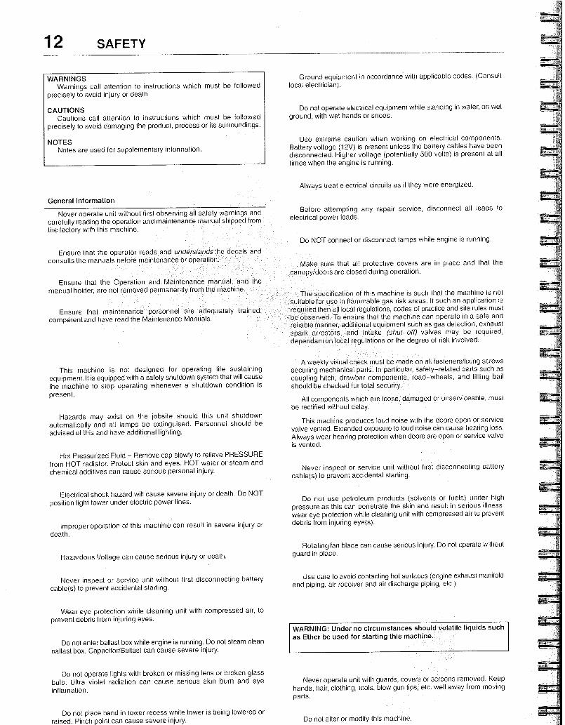
WARNINGS Warnings call attention to instructions which must be followed
precisely to avoid injury or death.
CAUTIONS Cautions call attention to instructions which must be followed
precisely to avoid damaging the product, process or its surroundings.
NOTES Notes are used for supplementary information.
Ground equipment in accordance with applicable codes. (Consult local electrician).
Do not operate electrical equipment while standing in water, on wet ground, with wet hands or shoes.
Use extreme caution when working on electrical components. Battery voltage (12V) is present unless the battery cables have been disconnected. Higher voltage (potentially 500 volts) is present at all times when the engine is running.
Aiways treat electrical circuits as if they were energ zed.
General Information
Never operate unit without first observing all safety warnings and carefully reading the operation and maintenance manual shipped from the factory with this machine.
Ensure that the operator reads and understands the decals and consults the manuals before maintenance or operation.
Ensure that the Operation and Maintenance manual, and manual holder, are not removed permanently from the machine.
Ensure that maintenance personnel are adequately trained competent and have read the Maintenance Manuals.
Before attempting any repair service, disconnect all leads to electrical power loads.
Do NOT connect or disconnect lamps while engine is running.
Make sure that all protective covers are in place and that the canopy/doors are closed during operation.
The specification of this machine is such that the machine is not suitable for use in flammable gas risk areas. If such an application is required then all local regulations, codes of practice and site rules must be observed. To ensure that the machine can operate in a safe and reliable manner, additional equipment such as gas detection, exhaust spark arrestors, and intake (shut-off) valves may be required, dependant on local regulations or the degree of risk involved.
This machine is not designed for operating life sustaining equipment. It is equipped with a safety shutdown system that will cause the machine to stop operating whenever a shutdown condition is present.
Hazards may exist on the jobsite should this unit shutdown automatically and all lamps be extinguised. Personnel should be advised of this and have additional lighting.
Hot Pressurized Fluid - Remove cap slowly to relieve PRESSURE from HOT radiator. Protect skin and eyes. HOT water or steam and chemical additives can cause serious personal injury.
Electrical shock hazard will cause severe injury or death. Do NOT position light tower under electric power lines.
Improper operation of this machine can result in severe injury or death.
Hazardous Voltage can cause serious injury or death.
Never inspect or service unit without first disconnecting battery cable(s) to prevent accidental starting.
Wear eye protection while cleaning unit with compressed air, to prevent debris from injuring eyes.
Do not enter ballast box while engine is running. Do not steam clean ballast box. Capacitor/Ballast can cause severe injury.
Do not operate lights with broken or missing lens or broken glass bulb. Ultra violet radiation can cause serious skin burn and eye inflamation.
Do not place hand in tower recess while tower is be ng lowered or raised. Pinch point can cause severe injury.
A weekly visual check must be made on all fasteners/fixing screws securing mechanical parts. In particular, safety-related parts such as coupling hitch, drawbar components, road-wheels, and lifting bail should be checked for total security.
All components which are loose, damaged or unserviceable, must be rectified without delay.
This machine produces loud noise with the doors open or service valve vented. Extended exposure to loud noise can cause hearing loss. Always wear hearing protection when doors are open or service valve is vented.
Never inspect or service unit without first disconnecting battery cable(s) to prevent accidental starting.
Do not use petroleum products (solvents or fuels) under high pressure as this can penetrate the skin and result in serious illness. wear eye protection while cleaning unit with compressed air to prevent debris from injuring eye(s).
Rotating fan blade can cause serious injury. Do not operate without guard in place.
Use care to avoid contacting hot surfaces (engine exhaust manifold and piping, air receiver and air discharge piping, etc.).
WARNING: Under no circumstances should volatile liquids such as Ether be used for starting this machine.
Never operate unit with guards, covers or screens removed. Keep hands, hair, clothing, tools, blow gun tips, etc. well away from moving parts.
Do not alter or modify this machine.
The following substances maybe produced during the operation of this machine: . brake lining dust . engine exhaust fumes
AVOID INHALATION
Ensure that adequate ventilation of the cooling system and exhaust gases is maintained at all times.
The following substances are used in the manufacture of this machine and maybe hazardous to health if used incorrectly:
engine lubricant • preservative grease
rust preventative diesel fuel battery electrolyte
AVOID INGESTION. FUMES
Safety data sheets lubricant supplier.
SKIN CONTACT AND INHALATION OF
lubricants should be obtained from the
Never operate the engine of this machine inside a building without adequate ventilation. Avoid breathing exhaust fumes when working on or near the machine.
Materials
This machine may include such materials as oil, diesel fuel, antifreeze, brake fluid, oillair filters and batteries which may require proper disposal when performing maintenance and service tasks. Contact local authorities for proper disposal of these materials.
When recycling or disposing of any electrical components, light bulbs etc., do not mix with general waste.
There is a separate collection system for used electronic products ii accordance with legislation that requires proper treatment, recovery and recycling.
contact your local authorities for the correct method of recycling.
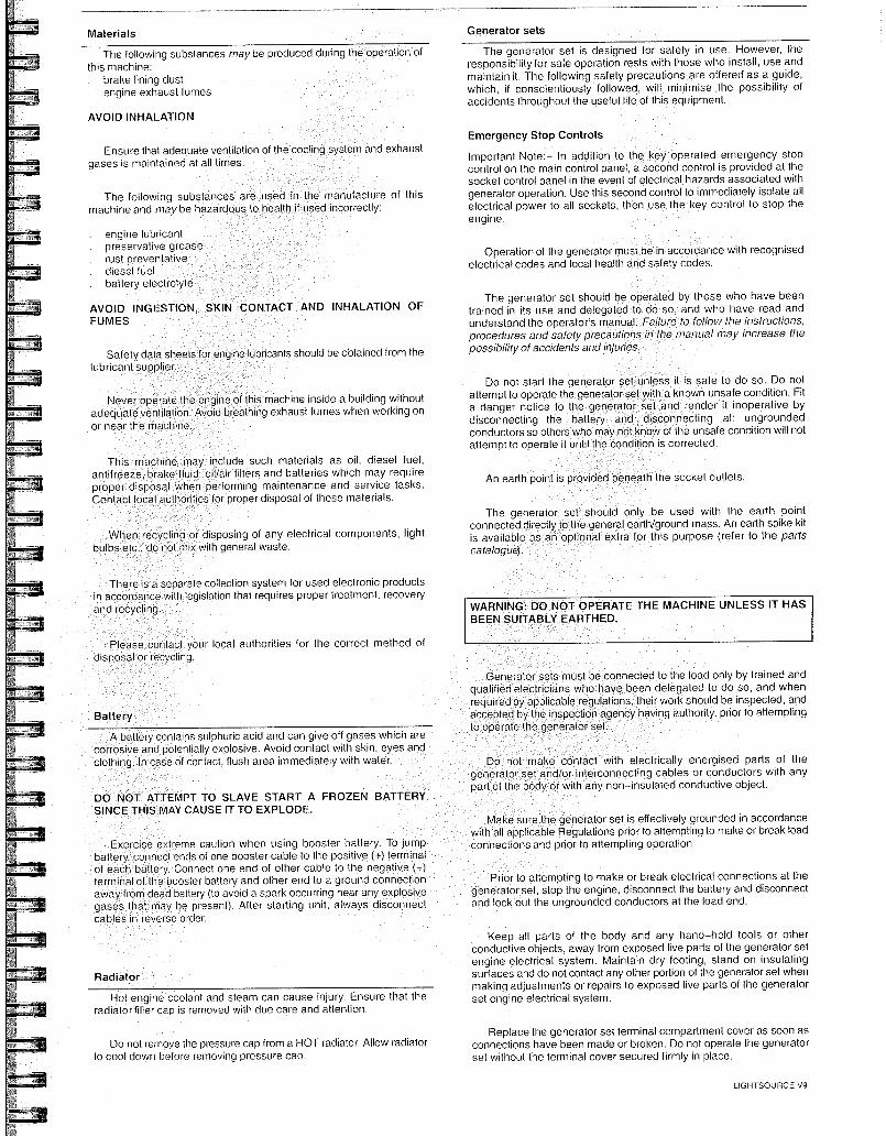
A battery contains sulphuric acid and can give off gases which are corrosive and potenlially explosive. Avoid contact with skin, eyes and clothing. In case of contact, flush area immediately with water.
DO NOT ATTEMPT TO SLAVE START A FROZEN BATTERY SINCE THIS MAY CAUSE IT TO EXPLODE.
Exercise extreme caution when using booster battery. To jump battery, connect ends of one booster cable to the positive (+) terminal of each battery. Connect one end of other cable to the negative (-) terminal of the booster battery and other end to a ground connection away from dead battery (to avoid a spark occurring near any explosive gases that may be present). After starting unit, always disconnect cables in reverse order.
Radiator
Hot engine coolant and steam can cause injury. Ensure that the radiator filler cap is removed with due care and attention.
Do not remove the pressure cap from a HOT radiator. Allow radiator lo cool down before removing pressure cap.
Generator sets
The generator set is designed for safety in use. However, the responsibility for safe operation rests with those who install, use and maintain it. The following safety precautions are offered as a guide, which, if conscientiously followed, will minimise the possibility of accidents throughout the useful life of this equipment.
Emergency Stop Controls
Important Note:- In addition to the key operated emergency stop control on the main control panel, a second control is provided at the socket control panel in the event of electrical hazards associated with generator operation. Use this second control to immediately isolate all electrical power to all sockets, then use the key control to stop the engine.
Operation of the generator must be in accordance with recognised electrical codes and local health and safety codes.
The generator set should be operated by those who have been trained in its use and delegated to do so, and who have read and understand the operator's manual. Failure to follow the instructions, procedures and safety precautions in the manual may increase the possibilityof accidents and injuries.
Do not start the generator set unless it is safe to do so. Do not attempt to operate the generator set with a known unsafe condition. Fit a danger notice to the generator set and render it inoperative by disconnecting the battery and disconnecting all ungrounded conductors so others who may not know of the unsafe condition will not attempt to operate it until the condition is corrected.
An earth point is provided beneath the socket outlets.
The generator set should only be used with the earth point connected directly to the general earth/ground mass. An earth spike kit is available as an optional extra for this purpose (refer to the parts
catalogue).
WARNING: DO NOT OPERATE THE MACHINE UNLESS IT HAS BEEN SUITABLY EARTHED,
Generator sets must be connected to the load only by trained and qualified electricians who have been delegated to do so, and when required by applicable regulations their work should be inspected, and accepted by the inspection agency having authonty, prior to attempting to operate the generator set.
Do not make contact with electrically energised parts of the generator set and/or interconnecting cables or conductors with any part of the body or with any non-insulated conductive object.
Make sure the generator set is effectively grounded in accordance with all applicable Regulations prior to attempting to make or break load connections and prior to attempting operation.
Prior to attempting to make or break electrical connections at the generator set, stop the engine, disconnect the battery and disconnect and lock out the ungrounded conductors at the load end.
Keep all parts of the body and any hand-held tools or other conductive objects, away from exposed live parts of the generator set engine electrical system. Maintain dry footing, stand on insulating surfaces and do not contact any other portion of the generator set when making adjustments or repairs to exposed live parts of the generator set engine electrical system.
Fleplace the generator set terminal compartment cover as soon as connections have been made or broken. Do not operate the generator set without the terminal cover secured firmly in place.
LIGHTSOURCE V9
14 SAFETY
Close and lock all access doors when the generator set is left unattended.
Do not use extinguishers intended for Class A or Class B fires on electrical fires. Use only extinguishers suitable for class BC or class ABC fires.
Keep the towing vehicle or equipment carrier, generator set, connecting cables, tools and all personnel at least 3 metres from all power lines and buried power cables, other than those connected to the generator set.
Attempt repairs only in clean, dry, well lighted and ventilated areas.
When parking always use the handbrake and, if necessary, suitable wheel chocks.
Make sure wheels, tyres and tow bar connectors are in safe operating condition and tow bar is properly connected before towing.
Do not store or transport hazardous or combustible materials in or on this unit.
Do not suspend this machine with other equipment hanging from the running gear.
Connect the generator set only to loads and/or electrical systems that are compatible with its electrical characteristics and that are within it's rated capacity.
Transport
When loading or transporting machines ensure that the specified lifting and tie down points are used.
When loading or transporting machines ensure that the towing vehicle, its size, weight, towing hitch and electrical supply are all suitable to provide safe and stable towing at speeds either, up to the legal maximum for the country in which it is being towed or, as specified for the machine model if lower than the legal maximum.
Ensure that the maximum trailer weight does not exceed the maximum gross weight of the machine (by limiting the equipment load), limited by the capacity of the running gear.
Note: Gross mass (on data plate) is for the basic machine and fuel only,
excluding any fitted options, tools, equipment and foreign materials.
Before towing the machine, ensure that:--
the tyres and towing hitch are in a serviceable condition. the canopy is secure. all ancillary equipment is stored in a safe and secure manner. the brakes and lights are functioning correctly and meet necessary road traffic requirements. break-away cables/safety chains are connected to the vehicle.
The machine must be towed in a level attitude in order to maintain correct handling, braking and lighting functions. This can be achieved by correct selection and adjustment of the vehicle towing hitch and, on variable height running gear, adjustment of the drawbar.
To ensure full braking efficiency, the front (towing eye) section must always be set level.
When adjusting variable height running gear:-
Ensure front (towing eye) section is set level
When raising towing eye, set rear joint first, then front joint.
When lowering towing eye, set front joint first, then rear joint.
After setting, fully tighten each joint by hand and then tighten further
to the next pin. Refit the pin.
Safety chains 1 connections and their adjustment
The legal requirements for the joint operation of the breakaway cable and safety chains are as yet unidentified by 71/320/EEC or UK regulations. Consequently we offer the following advice / instructions.
Where brakes only are fitted:
a) Ensure that the breakaway cable is securely coupled to the handbrake lever and also to a substantial point on the towing vehicle.
b) Ensure that the effective cable length is as short as possible, whilst still allowing enough slackness for the trailer to articulate without the handbrake being applied.
Where brakes and safety chains are fitted:
a) Loop the chains onto the towing vehicie using the towing vehicle hitch as an anchorage point, or any other point of similar strength.
b) Ensure that the effective chain length is as short as possible whitst still allowing normal articulation of the trailer and effective operation of the breakaway cable.
a) Loop the chains onto the towing vehicle using the towing vehicle hitch as an anchorage point, or any other point of similar strength.
b) When adjusting the safety chains there should be sufficient free length in the chains to allow normal articulation, whilst also being short enough to prevent the towbar from touching the ground in the event of an accidental separation of the towing vehicle from the trailer.
Before towing
Make sure wheels, tires and tow bar connectors are in safe operating condition and tow bar is properly connected before towing.
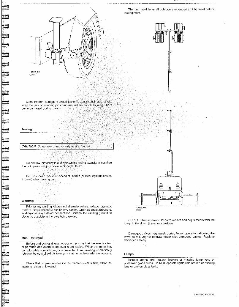
nove with mast extended. CAUTION: Do not OW 0
The unit must have all outriggers extended and be level before raising mast.
T2930_00 06/08
Store the front outriggers and all jacks. To secure each jack handle, wrap the jack positioning pin chain around the handle to keep it from being damaged durino towing.
Towing
Do not tow this unit with a vehicle whose towing capacity is less than the unit gross weight shown in General Data.
Do not exceed maximum speed of 80km/h (or local legal maximum, if lower) when towing unit.
Welding
Prior to any welding, disconnect alternator relays, voltage regulator, meters, circuit breakers and battery cables. Open all circuit breakers, and rernove any external connections. Connect the welding ground as close as possible to the area being welded.
Mast Operation
Before and during all mast operation, ensure that the area is clear of persons and obstructions over a 2m radius. When the mast has completed its normal travel, or is prevented from travelling, immediately release the control swilch, to ensure that no cable overtension occurs.
Check that no person is behind the machine (within 10m) while the tower is raised or lowered.
Inspect lamps and replace broken or missing lamp lens or punctured glass bulbs. Do NOT operate lights with broken or missing lens or broken glass bulb.
LIGHTSOURCE V9
T2929_00 09/08
DO NOT climb on tower. Perform repairs and adjustments with the tower in the down (transport) position.
Damaged cables may break during tower operation allowing the tower to fall. Do not operate tower with damaged cables. Replace damaged cables.
Lamps
This machine can be fitted with bund equipment to contain leakages and spillages, which occur within the machine enclosure.
The bund will contain all fluids normally installed in the machine, plus an additional 10%.
When fitted with bund, the machine must on levelled.
y be operated when
Drains for engine water, engine oil and fuel tank are loca ed at the rear right corner of the machine.
Draining of contaminated fluids
Contaminated fluid must be removed by authorized personnel only.
Captured fluids can be drained from the bund by removal of the plug at the rear base of the frame. This plug must be replaced after draining.
Drainage of machine fluids
16 SAFETY
Flammable fuels
Do not fill the fuel tank when the engine is running.
Do not smoke or use an open flame in the vicinity of the light tower or fuel tank.
Do not permit smoking, or open flame, or sparks to occur near the battery, fuel, cleaning solvents or other flammable substances and explosive gases.
BUNDED BASE
During maintenance operations, drain machine fluids using the drain ports indicated.
WARNING: Major leakages or spillages must be drained before the machine is towed.
Disposal of contaminated fluids from bund
Contaminated fluids removed from bund, must be disposed of to designated containers only.
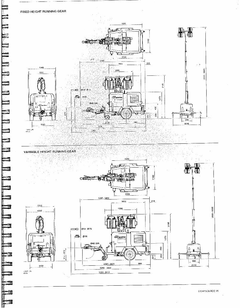
FIXED HEIGHT RUNNING GEAR
VARIABLE HEIGHT RUNNING GEAR
130
219 1602
335 3513
1656
• tOgrill~mir
0521 iterm,
rymakil/i /ar4
1556
3297-3459
cMa
980 980 2267-2429
3282-3444 2640
1506
040 0111
068 076
050
1---011114
,2933 30 00 ,00 -
LIGHTSOURCE V9
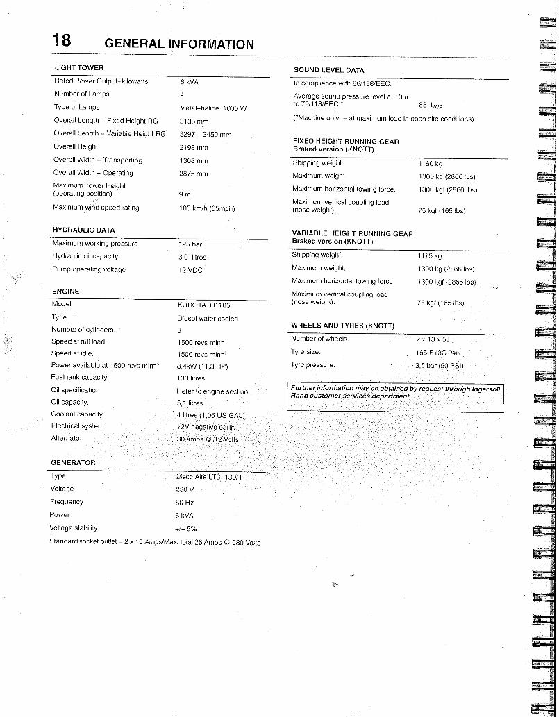
HYDRAULIC DATA
Maximum working pressure
125 bar
Hydraulic oil capacity 3,0 litres
Pump operating voltage 12 VDC
ENGINE
KUBOTA D1105
Diesel water cooled
3
1500 revs min -1
1500 revs min-1
8,4kW (11,3 HP)
130 litres
Refer to engine section
5,1 litres
4 11 es (1,06 US GAL)
12V negative earth
30 amps @ 12 Volts
GENERATOR
Type
Voltage
Frequency
Power
Voltage stability
VARIABLE HEIGHT RUNNING GEAR Braked version (KNOTT)
Shipping weight. 1175 kg
Maximum weight. 1300 kg (2866 lbs)
Maximum horizontal towing force. 1300 kgf (2866 lbs)
Maximum vertical coupling load (nose weight). 75 kgf (165 lbs)
WHEELS AND TYRES (KNOTT)
Number of wheels. 2 x 13 x 5J
Tyre size. 165 R13C 94N
Tyre pressure. 3,5 bar (50 PSI)
Further information may be obtained by request through Ingersoll Rand customer services department.
Model
Type
Number of cylinders
Speed at full load.
Speed at idle.
Power available al 1500 revs min -1
Fuel tank capacity
Oil specification
Oil capacity.
Coolant capacity
Electrical system.
Alternator
Standard socket outlet - 2 x 16 Amps/Max. total 26 Amps @ 230 Volts
Mecc Alte LT3
230 V
50 Hz
6 kVA
+/- 6%
130/4
18 GENERAL INFORMATION
LIGHT TOWER SOUND LEVEL DATA
Rated Power Output-kilowatts 6 kVA In compliance with 86/188/EEC.
Number of Lamps
Type of Lamps
Overall Length - Fixed Height RG
Overall Length - Variable Height RG
Overall Height
Overall Width - Transporting
Overail Width - Operating
Maximum Tower Height (operating position)
Maximum wind speed rat ng
4
Metal-halide 1000 W
3135 mm
3297 - 3459 mm
2198 mm
1368 mm
2875 mm
9 m
105 km/h (65mph)
Average sound pressure level al 10m to 79/113/EEC.*
88 LWA
(Machine only at maximum load in open site conditions)
FIXED HEIGHT RUNNING GEAR Braked version (KNOTT)
Shipping weight. 1160 kg
Maximum weight. 1300 kg (2866 lbs)
Maximum horizontal towing force. 1300 kgf (2866 lbs)
Maximum vertical coupling load (nose weight). 75 kgf (165 lbs)
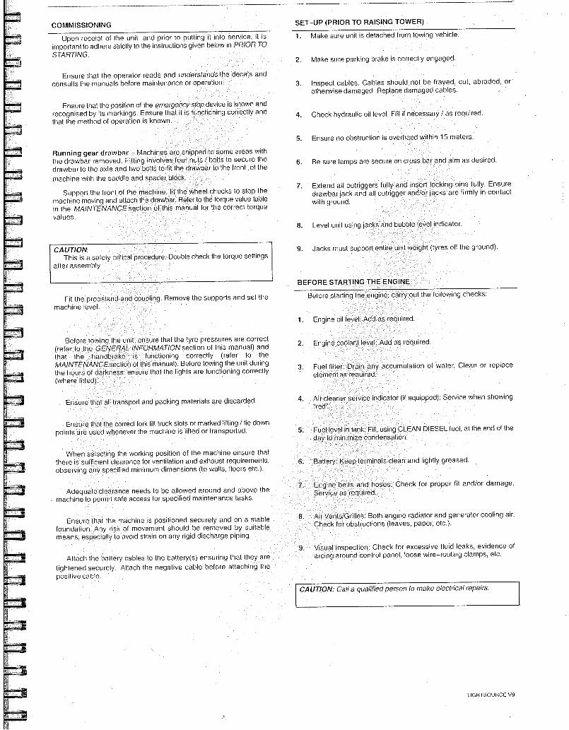
COMMISSIONING
Upon receipt of the unit, and prior to putting it into service, it is important to adhere strictly to the instructions given below in PRIOR TO STARTING.
SET-UP (PRIOR TO RAISING TOWER)
1. Make sure unit is detached from towing vehicle.
2. Make sure parking brake is correctly engaged.
. Engine coolan leve Add as required.
Air cleane "red".
ansport and packing materials are discarded. seivice indicator (if equipped): Service when showing
erminals clean and lightly greased. Battery Keep t
proper fit and/or damage. Engine belts and hoses: Check fo Service as required. Adequate clearance needs to be allowed around and above the
machine to permit safe access for specified maintenance tasks.
Ensure that the machine is positioned securely and on a stable foundation. Any risk of movement should be removed by suitable means, especially to avoid strain on any rigid discharge piping.
Attach the baltery cables to the battery(s) ensuring that they are tightened securely. Attach the negative cable before attaching the positive cable.
Air Vents/Grilles: Both engine radiator and generator cooling air. Check for obstructions (leaves, paper, etc.).
Visual inspection: Check for excessive fluid leaks, evidence of arcing around control panel, loose wire-routing clamps, etc.
CAUTION: Call a qualified person to make electrical repairs.
Ensure that the operator reads and understands the decals and consults the manuals before maintenance or operation.
Ensure that the position of the emergency stop device is known and recognised by its markings. Ensure that it is functioning correctly and that the method of operation is known.
Running gear drawbar - Machines are shipped to some areas with the drawbar removed. Fitting involves four nuts / bolts to secure the drawbar to the axle and two bolts to fit the drawbar to the front of the machine with the saddle and spacer block.
Support the front of the machine, fit the wheel chocks to stop the machine moving and attach the drawbar. Refer to the torque value table in the MAINTENANCE section of this manual for the correct torque values
E3efore towing the unit, ensure that the tyre pressures are correct (refer to the GENERAL INFORMATION section of this manual) and that the handbrake is functioning correctly (refer to the MAINTENANCEsection of this manual). Before towing the unit during the hours of darkness, ensure that the lights are functioning correctly (where fitted).
Ensure that the correct fork lift truck slots or marked liffing / tie down points are used whenever the machine is lifted or transported.
When selecting the working position of the machine ensure that there is sufficient clearance for ventilation and exhaust requirements, observing any specified minimum dimensions (to walls, floors etc.).
LIGHTSOURCE V9
Fit the propstand and machine level.
coupling. Remove the supports and set the
4. Check hydraulic oil level. FilI if necessary / as required.
5. Ensure no obstruction is overhaed within 15 meters.
6. Be sure lamps are secure on cross bar and aim as desired.
Jacks must support entire unit weight (tyres off the ground).
Before starting the engine, carry out the following checks:
1. Engine oil level: Add as required.
3. Fuel filter: Drain any accumulation of water. Clean or replace element as required.
Fuel level in tank: Fill, using CLEAN DIESEL fuel, at the end of the day to minimize condensation.
3. Inspect cables. Cables should not be frayed, cut, abraded or otherwise damaged. Replace damaged cables.
7. Extend all outriggers fully and insert locking pins fully. Ensure drawbar jack and all outrigger and/or jacks are firmly in contact with ground.
. Level unit using jacks and bubble evel indicator.
BEFORE STARTING THE ENGINE
CAUTION: This is a safety critical p
after assembly ocedure Double check the torque settings
20 OPERATING INSTRUCTIONS
4 --
MAST DOWN
Yit1131
ilm OFF
6 7
/ I i I
1
r-- 2 1
1 3 2
L- 1---- .. 1
I I
HOURMETER
151 Lejl [01 —I
MAST UP EXTERNAL TIMER HOURS
SaECTOR AUTO START
T2901 RevIsK,n 00 06/08 13 12
AUTO
MANUAL
23235294 LAMP TILT GENFERATOR
8
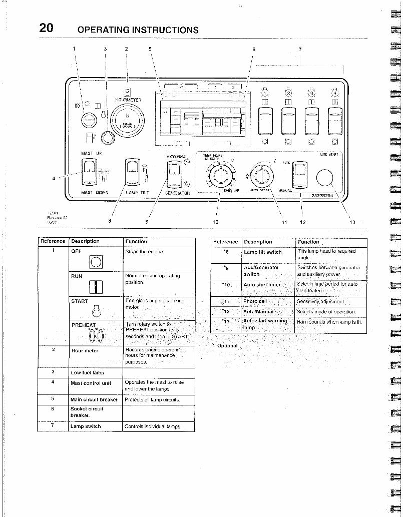
* Optional
Reference Description Function
1 OFF Stops the eng ne.
0
RUN Normal engine operating position.
START
8 Energises engine cranking motor.
PREHEAT
0-0
Turn rotary switch to PREHEAT position for 5 seconds and then to START.
- 2 Hour meter Records engine operating
hours for maintenance purposes.
3 Low fuel lamp
4 mast control unit Operates the mast to raise and lower the lamps,
5 Main circuit breaker Protects all lamp circuits.
6 Socket circuit
breaker.
7 Lamp switch Controls individual lamps.
Reference Description Function
*8 Lamp tilt switch Titts lamp head to required angle,
*9 Aux/Generator
switch
Switches between generator and auxiliary power.
*10 Auto start timer Selects time period for auto start feature.
* 11 Photo cell Sensitivity adjustnent.
12 Auto/Manual Selects mode of operation.
* 13 Auto start waroir 1 9 lamp
1-lorn solinds when larnp 's lit.
LIGHTSOURCE V9
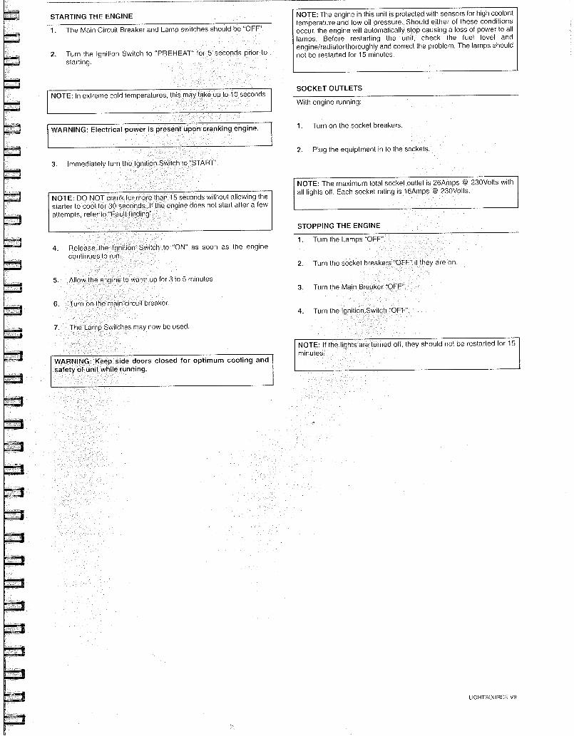
STARTING THE ENGINE
NOTE: In extreme cold temperatures, th's may take up to 10 seconds.
WARNING: Electrical power is present upon cranking engine.
3. Immediately turn the Ignition Switch to "START''.
NOTE: DO NOT crank for more than 15 seconds without allowing the starter to cool for 30 seconds. If the engine does not start after a few attempts, refer to "Fault finding".
• Release the Ignition Switch to ON" as soon as the engine continues to run.
up for 3 to 5 minutes.
Tu n on the I aln cIrcul
Switches may now be used.
WARNING: Keep side doors closed for optimum cooling and safety of unit while running.
NOTE: The engine in this unit is protected with sensors for high coolant temperature and low oil pressure. Should either of these conditions occur, the engine will automatically stop causing a loss of power to all lamps. Before restarting the unit, check the fuel level and engine/radiatorthoroughly and correct the problem. The lamps should not be restarted for 15 minutes.
SOCKET OUTLETS
With engine running:
1. Turn on the socket breakers.
2. Plug the equiptment in to the sockets.
NOTE: The maximum total socket outlet is 26Amps @ 230Volts with all lights off. Each socket rating is 16Amps @ 230Volts.
"OFF
1. Turn the Lamps "OFF"
2. Turn the socke
3. Turn the Main Breaker
NOTE: If the lights a minutes.
urned off, they should not be restarted for 15
STOPPING THE ENGINE
4. Turn the Ignition breaker.
The Lamp
1. The Main Circuit Breaker and Lamp switches should be "OFF".
2. Turn the Ignition Switch to "PREHEAT starting.
in Make sure that the pin has engaged and locked the towe
position.
Use the mast cont ol s itch to lower the
position.
1. Start the engine.
2. Use the mast control switch to raise the tower.
Raising the tower
3. Lift the pin [2] to rotate tower. Release the pin after rotating the
tower to the desired position.
1. Start the engine.
2. Switch the lamps off.
3. Lift the pin [2] to rotate tower. Release the pin after rotating the
tower to the desired position.
Lowering the tower
WARNING: Beware of lamps lowering when operating under mast
area.
1. Connect the machine to the vehicle.
2. Rotate the lamps to transport position and secure by fitting straps
[1] around the lamp bodies.
WARNING: The lamp bodies may be HOT.
22 OPERATING INSTRUCTIONS
Check that no obstruction is overhead.
Before operating the mast, inspect the cable
damaged cables if necessary.
or damage. Replace
ower to transport
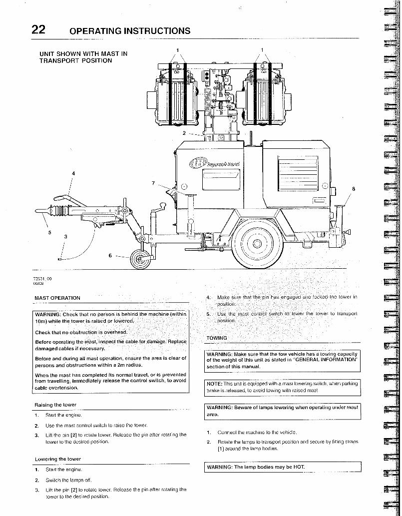
UNIT SHOWN WITH MAST IN TRANSPORT POSITION
1
4
7
5 3
6
T2931_00 06/08
MAST OPERATION
TOWING
WARNING: Make sure that the tow vehicle has a towing capacity of the weight of this unit as stated in "GENERAL INFORMATION"
section of this manual.
NOTE: This unit is equipped with a mast lowering switch, when parking
brake is released, to avoid towing with raised mast.
el lib~ agincd1
0
WARNING: Check that no person is behind the machine (within
10m) while the tower is raised or lowered.
Before and during all mast operation, ensure the area is clear of
persons and obstructions within a 2m radius.
When the mast has completed its normal travel, or is prevented from travelling, immediately release the control switch, to avoid
cable overtension.
Release hand brake [4].
Check that the units brakes are operating correctly.
Unit is ready to be towed
10. Attach the brake actuator breakaway chain /cable [3].
11. Make sure the light tower lighting is working properly, in accordance to the towing vehicle's lighting as well as local regulations.
12. Connect lighting plug.
13. Remove wheel chocks.
14.
15.
16.
Do not use the eye o parts.
ed inside or on top of the mach ne. 1. No loose objecls are sto
ts hung onto or under the machine. 2. No additional equipmet
3. Make sure that the tow vehicle hitch [5] is the proper size to securely connect to the eye or coupler on the unit.
4. Check eye or coupler bolts for any looseness or wear. Tighten or
replace as required.
5. Check the wheels.
6. Position the tow vehicle to align the hitch with the eye or coupler
[5].
7. Stand aside while operating the jockey wheel [6]
or coupler onto the hitch.
8. Secure the hitch.
9. Make sure outriggers and jacks are stored in transport position and the handles are secured by the chains.
RE-STARTING AFTER AN EMERGENCY STOP
1f the machine has been switched off because of a machine malfunction, then identify and correct the fault before attempting to re-start.
if the machine has been switched off for reasons of safety, then ensure that the machine can be operated safely before re-starting.
Refer to the PRIOR TO STARTING and STARTING THE UNIT instructions earlier in this section before re-starting the machine.
MONITORING DURING OPERATION
Should any of the safety shut-down conditions occur, the unit will stop. These are:
. Low engine oil pressure
High engine water temperature
DECOMMISSIONING
When the machine is to be permanently decommissioned or dismantled, it is important to ensure that all hazard risks are either eliminated or notified to the recipient of the machine. 1n particular:-
Do not destroy batteries or components containing asbestos without containing the materials safely.
LIFTING THE MACHINE
Before lifting the machine, carry out the following checks
• Do not dispose of any pressure vessel that is not clearly marked with its relevant data plate information or rendered unusable by drilling, cutting etc.
. Do not allow lubricants or coolants to be released into land surfaces or drains.
. Do not dispose of a complete machine without documentation relating to instructions for its use,
3. Any device used for lifting IS rated a a minimum of 2000kg
4. No personnel should be on or under the during lifting.
machlne at any time
LIGHTSOURCE V9
WARNING: Make sure the hitch is completely engaged to the tow vehicle and is secure. Failure to do so couId result in serious personal injury.
24
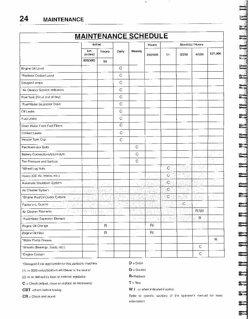
MAINTENANCE SCHEDULE Initial.
Daily Weekly
Hours Monthly/ Hours
km (miles)
Hours 200/400 1/- 3/250 6/500 12/1,000
850(500) 50
Engine Oil Level C
- Radiator Coolant Level C
Gauges/Lamps C
-Air Cleaner Service Indicators C
Fuel Tank (Fill at end of day) C
- FuelANater Separator Drain C
Oil Leaks C
Fuel Leaks C
Drain Water From Fuel Filters C
Coolant Leaks C
Header Tank Cap. C
Fan/Alternator Belts C
Battery Connections/Electrolyte C
Tire Pressure and Surface C
-Wheel Lug Nuts
Hoses (Oil, Air, Intake, etc.)
Automatic Shutdown System
Air Cleaner System
- Engine Rad/Oil Cooler Exterio
Fasteners, Guards
Air Cleaner Elements R/W1
*Fuel/Water Separator Element
Engine Oil Change R R/—
Engine Oil Filter R R/—
-Water Pump Grease. R
"Wheels (Bearings, Seals, etc.) C
- Engine Coolant C
*Disregard if not appropriate for this particular machine.
(1) or 3000 miles/5000km whichever is the sooner
(2) or as defined by local or national legislation
C = Check (adjust, clean or replace as necessary)
CBT =check before towing.
CR = Check and report
D = Drain
G = Grease
R=Replace
T = Test
W 1 =or when indicated if earlier.
Refer to specific sections of the operator's manual for more
information
MAINTENANCE
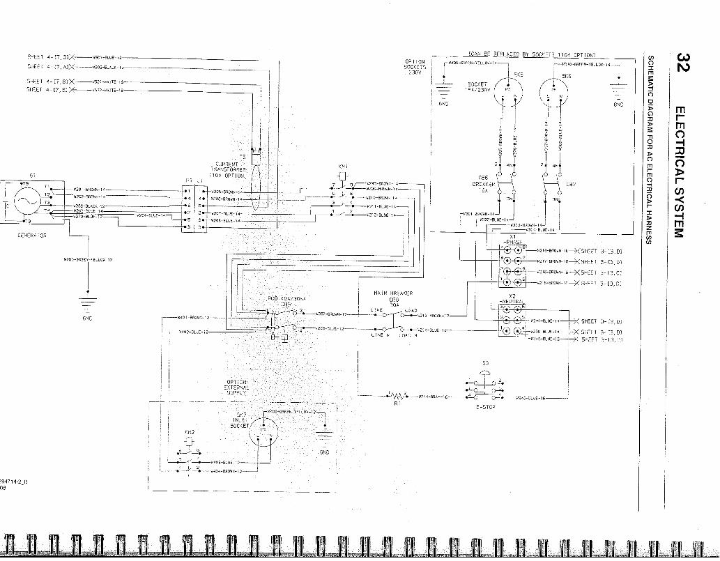
c") SC
HE
MA
TIC
DIA
GR
AM
FO
R A
C E
LE
CT
RIC
AL
HA
RN
ES
S
OP1108 SOCKETS
230V
-41300 -06005 - Y ELLOW - 14
SKS
SOCKET /7" 0A/230V PE
N
4245 BLUE 70
S3
2
4 —14244 GRA 10 •;LO R1
E-STOP
SHEET 4 - [7,82X E521-44EI6E-15
SHEET 4 - [7,,B]>< 41522 r: IE
08,8 BREAKEP
ISA
1-201) A0A/301710 MA N cBrR,EAKER
085 i NE 30A LOAD
0-4.-14213-360145 12
t311 647-11--0-4-•---W250-BLU 2
0108 LOAL1 N
SHEET 4-0,21X 4501 BLUE 12
SHEET 4- 0,A1>< 41502 ELACK 12
■1■3 4 4 03-01 ■ 30-1 -
•I-411. 20 4404 060434 12
OPTION EXTENAL
SUP'L 7
- 1;301 -srtotiN-14
4303-650145-14 3304 ELUE 14
„4, rF
X2 -NEUTRAL
13® ® 6
—W110 -GREEN-YELL OW- 14 —4
X SHEET 3-[3,DI
X SHEET 3- 0, 01
.,>< SHEET 3-13, C3
11218 E004N-10 —X SHEE T 3- [3.01
4217 031045 10 X SHEE1 3- [3,01
42 1 6-eRm-16--X5HEET 3 - [3,0]
0210 ER031,1 - 10 —X SHEE l■ 3- [3,01
2€■---05 4240 BLU: 11
ELUB-12 44230 BLUE 14
L14246-ELUE 16
END
X 1 -PHASE
----4201-ER0WN-14
— 4202 -BRO1414-14
12505-ACE 12
41203-EL 00- 14
—14270-ELUE-14
■-• -•
• 4224-ELVE-14 —■ 2
I • .S
• 3
GENERATOP
384714-2_B 08
GND 4401 66045-12
1088 BE PEPLACED BV SOCKETS 110V OPTION)
CURRENT TRANSFORMER
110V OPTION
KIM1
• 421 1 Il_LFL 14
1 • -11--?•--14212 BLEE 14
---
! Gr7tD
•
W255-GREEN LLO 2
1 •-ri 14005-060
-i-E205 -E30141 E.
2 4207 ELU_
S •01- 5120E-BLIIE-1
3.
KUBOTA D1105 - ENGINE
CONTENTS
42 FOREWORD
43 EXTERNAL VIEW
44 GENERAL INFORMATION
Main data and specifications
Engine identification
Ingersoll Rand engine after sales support
45
FUEL, LUBRICANT, AND COOLANT
Fuel
Lubricant
Coolant
47 OPERATION
Check before operation
Check and operation after start- up
Operation and care of a new engine
52 MAINTENANCE SCHEDULE
53 PERIODICAL INSPECTION AND MAINTENANCE
Lubricating system
Cooling system
Fuel system
Air intake system
Routine maintenance
58 TROUBLESHOOTING
LIGHTSOURCE V9
The INGERSOLL RAND industrial diesel engines are a product of long years of experience, advanced technology, and up-to date production facilities. 1NGERSOLL RAND takes great pride in the superior durability and operating economy of these engines.
ln order to get the fullest use and benefit from your engine, it/s important that you operate and maintain it correctly. This Manual is designed to help you do this.
Please read this Manual carefully and follow its operating and maintenance recommendations. This will ensure many years of Irouble-free and economical engine operation.
Should your engine reguire servicing, please contact your nearest INGERSOLL RAND branch or distributor.
All information, illusfrations, and specifications contained in this Manual are based on the latest product infonnation available at the time of publication.
INGERSOLL RAND reserves the right to make changes in this Manual at any time without prior notice.
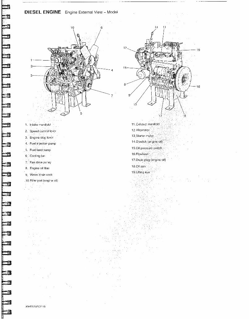
DIESEL ENGINE Engine External View - Model
10 14 11
19
1
15
3
16
13
1. Intake manifold
2. Speed control lever
stop lever
Fuel injection pump
5 Fuel feed pump
6 Cooling fan
7. Fan d ive pulley
8. Engine oil filter
9. Water drain cock
10.Filler port (engine oil)
11. Exhaust manifold
12.Alternator
13.Starter motor
14.Dipstick (engine oil)
15.011 pressure switch
16. Flywh eel
17.Drain plug (engine oil)
18.0i1 pan
19.Lifting eye
LIGHTSOURCE V9
Initial.
Weekly
Hours Monthly/ Hours
km (miles)
Hours Daily 2001400 1/- 3/250 6/500 1211,000
850(500) 50
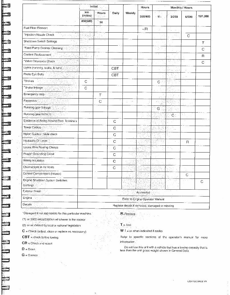
Fuel Filter Element -/R
injection Nozzle Check
Shutdown Switch Settings T
*Feed Pump Strainer Cleaning. C
Coolant Replacement R
"Valve Clearance Check C
Lights (running, brake, & turn) CBT
Pintle Eye Bolts CBT
'Brakes
* Brake linkage
Ernergency stop T
Fasteners C
Running gear linkage
Running gear bolts(1)
Evidence of Arang A ound Elect. Terminals C
Tower Cables C
Nylon Guides / Slide check C
Hydraulic Oil Level C
Loose Wi e Rouling Clamps C
Proper Grounding Circuit C
Wiring Insula ion C
Obstructions in Air Vents C
Control Compartment (In erior)
Engine Shuldown System Switches
(setting) C
Exterior Finish As needed
Engine Refer to Engine Operator Manual
Decals Replace decals il removed, damaged or missing
*Disregard if not appropriate for this particular machine.
(1) or 3000 miles/5000km whichever is the sooner
(2) or as defined by local or national legislation
C Check (adjust, clean or replace as necessary)
CBT = check before
CR = Check and report
D = Drain
G Grease
R=Replace
T = Test
W 1 = or when indicated if earlier.
Refer to specific sections of the operator's manual for more
information.
Do not tow this unit with a vehicle that has a towing capacity that is less than the unit gross weight shown in General Data.
LIGHTSOUIRCE V9
eassamo.
ROUTINE MAINTENANCE
This section refers to the various components which require periodic maintenance and replacement.
The SERVICE/MAINTENANCE CHART indicates the various components' descriptions and the intervals when maintenance has to take place. Oil capacities, etc., can be found in the GENERAL INFORMATION section of this manual.
For any specification or specific requirement on service or preventative maintenance for the engine, refer to the Engine Manufacturees Manual.
Ensure that maintenance personnel are adequately trained, competent and have read the Maintenance Manuals.
Prior to attempting any maintenance work, ensure that:-
. the machine cannot be started accidentally or otherwise, by posting warning signs and/or fitting appropriate anti-start devices.
. all residual electrical power sources (mains and battery) are isolated.
Prior to opening or removing panels or covers to work inside a machine, ensure that:-
. anyone entering the machine is aware of the reduced level of protection and the additional hazards, including hot surfaces and intermittently moving parts.
. the machine cannot be started accidentally or otherwise, by posting warning signs and/or fitting appropriate anti-start devices.
Prior to attempting any maintenance work on a running machine, ensure that:-
ELECTRICAL SYSTEM
WARNING: Always disconnect the battery cables before performing any maintenance or service.
Inspect the safety shutdown system switches and the instrument panel relay contacts for evidence of arcing and pitting. Clean where necessary.
Check the mechanical action of the components.
Check the security of electrical terminals on the switches and relays i.e. nuts or screws loose, which may cause local hot spot oxidation.
Inspect the components and wiring for signs of overheating i.e. discolouration, charring of cables, deformation of parts, acrid smells and blistered paint.
ELECTRICAL TERMINALS
Check daily for evidence of arcing around the electrical terminals.
GROUNDING CIRCUIT
Daily check that the grounding circuit is in accordance with local code requirements. Check to ensure continuity between the grounding terminal, frame, generator and engine block.
WIRING INSULATION
Daily check for loose, or frayed wiring insulation or sleeving.
BATTERY
Keep the battery terminals and cable clamps clean and lightly coated with petroleum jelly to prevent corrosion.
26 MAINTENANCE
. the work carried out is limited to only those tasks which machine to run.
equire the The retaining clamp should be kept tight enough to prevent the
battery from moving.
• the work carried out with safety protection devices disabled or removed is limited to only those tasks which require the machine to be running with safety protection devices disabled or removed.
• all hazards present are known (e.g. pressurised components, electrically live components, removed panels, covers and guards, extreme temperatures, inflow and outflow of air, intermittently moving parts, safety valve discharge etc.).
• appropriate personal protective equipment is worn.
• loose clothing, jewelry, long hair etc. is made safe.
. warning signs indicating that Maintenance Work is in Progress are posted in a position that can be clearly seen.
Upon completion of maintenance tasks and prior to returning the machine into service, ensure that:-
the machine is suitably tested.
all guards and safety protection devices are refitted.
all panels are replaced, canopy and doors closed.
hazardous materials are effectively contained and disposed of.
INSTRUMENTS
Inspect the instrument lamps gauges and switches prior to start-up and during operation to ensure proper functioning.
CONTROL COMPARTMENT
Every six months or 500 hours with the unit OFF", perform visual inspection for loose connections, dirt, arcing, damage to electrical components.
TOWER CABLES
Each day the tower lifting cables should be inspected to ensure the ends are attached securely. The cables should be checked for fraying or other damage and replaced if damaged. Also the pulleys should be checked for unusual wear or damage and replaced if worn excessively or damaged.
WIRE ROUTING CLAMPS
Daily check for loose wire routing clamps. Clamps must be secure and properly mounted. Also check wiring for wear, delerioration and vibration abrasion.
TOWER GUIDES
Every month inspect all of the tower guides for proper operation. Clean sliding surfaces. Replace any missing or damaged parts before raising the tower.
ENGINE RADIATOR
Check the coolant level in the radiator. The coolant must cover the tubes in the top tank (approximately 1 inch high on a clean measuring rod, stuck down filler neck).
WARNING: Remove cap slowly to relieve Pressure from HOT radiator. Protect skin and eyes. Hot water or steam and chemical additives can cause serious personal injury.
The engine coolant system is normally filled with a 50/50 mixture of water and ethylene glycol. This tpermanent type anti-freeze contains rust inhibitors and provides rod tection to -35°F (-37°C). The use of such a mixture is recommenge orzboth summer and winter operation.
g p It is recommended to test the fr rotection of the coolant every six months or prior to freezingteeempneratures. RePlenish with a fresh e mixture every twelve months. ac month , inspect the rapiator exterior . if
h i
for obstructions, dirt and debris pvresent, blow water or compressed air containing a non-flammable ent between the fins in a direction opposite the normal air flow. cSohmosm
uoidertchieeiraPdfoiadtourcbt eacnidoglgheed sinutpeprnliaeirs lY, reverse flushing, using a recommended procedure, may correct the problem.
The engine coolant system is normally filled with a 50/50 mixture of water and ethylene glycol. This permanent type anti-freeze contains rust inhibitors and provides protection to -35°F (-37°C). The use of such a mixture is recommended for both summer and winter operation
It is recommended to test the freezing protection of the coolant every six months or prior to freezing temperatures. Replenish with a fresh mixture every twelve months.
Each month, inspect the radiator exterior for obstructions, dirt and debris. if present, blow water or compressed air containing a non-flammablesolvent between the fins in a direction opposite the normal air flow. Should the radiator be clogged internally, reverse flushing, using a commercial product and the supplier's recommended procedure, may correct the problem.
ENGINE PROTECTION SHUTDOWN SYSTEM
The operation of the engine protection shutdown system should be checked every month, or whenever it appears not to be operating properly. The three switches involved in this protective shutdown system are the engine coolant high temperature switch, the engine oil pressure switch and the low fuel switch. (optional)
The engine oil pressure switch prevents the engine from operating with low oil pressure. Once a month, remove a wire from the engine oil pressure switch to check the shutdown system for proper operation.
Test the engine oil pressure switch by removing it and connecting it to a source of controlled pressure while monitoring an ohmmeter connected to the switch terminals.
As pressure is applied slowly from the controlled source, the switch should close at 12 psi (84 kPa) and show continuity through the contacts. As the pressure is slowly decreased to 10 psi (70 kPa) the' contacts should open and the ohmmeter should show a lack of continuity through the contacts. Replace a defective switch before continuing to operate the unit.
Once a year, the temperature actuated switch should be tested by removing it from the unit and placing it in a bath of heated oil. The engine coolant high temperature switch will require a temperature of approximately 220°F (104°C) to actuate.
NOTE: The engine temperature switch does NOT offer protection when NO coolant is present. Test the switch operation by connecting an ohmmeter between the two wire terminals. The ohmmeter should show zero ohms. When the switch is placed in the heated oil bath and its contact open, the ohmmeter should indicate infinite ohms. Tap the switch lightly during the checking operation. Replace any defective switch before continuing to operate the unit.
CAUTION: Never operate the unit with a defective safely shutdown
switch or by by-passing a switch.
AIR FILTER ELEMENTS
The air filter should be inspected regularly (refer to the SERVICE/MAINTENANCE CHART) and the element replaced when the restriction indicator shows red or every 6 Months (500 hours), whichever comes first. The dust collector box(es) should be cleaned daily (more frequently in dusty operating conditions) and not allowed to become more than half full.
CAUT1ON: Never remove and replace element(s) when the machine
is running.
Clean the exterior of the filter housing and remove the filter element releasing the nut.
Inspection
Check for cracks, holes or any other damage to the element by holding it up to a light source, or by passing a lamp inside.
Check the seal at the end of the element and replace if any sign of damage is evident.
Reassembly
Assemble the new element into the filter housing ensuring that the seal seats properly.
Reset the restriction indicator by depressing the rubber diaphragm.
Assemble the dust collector box parts, ensuring that they are correctly positioned.
Before restarting the machine, check that all clamps are tight.
VENTILATION
Always check that the air inlets and outlets are dear of debris etc.
CAUTION: NEVER clean by blowing air inwards.
LIGHTSOURCE V9
28 MAINTENANCE
COOLING FAN DRIVE
Periodically check that the fan mounting bolts in the fan hub have not loosened. lf, for any reason, it becomes necessary to remove the fan or re-tighten the fan mounting bolts, apply a good grade of commercially available thread locking compound to the bolt threads and tighten to the torque value shown in the TOROUE SETTING TABLE later in this section.
The fan belt(s) should be checked regularly for wear and correct tensioning.
FUEL SYSTENI
The fuel tank should be filled daily or every eight hours. To minimise condensation in the fuel tank(s), it is advisable to top up after the machine is shut down or at the end of each working day. At six month intervals drain any sediment or condensate that may have accumulated in the tank(s).
TYRES/TYRE PRESSURE
See the GENERAL INFORMATION section of this manual.
RUNNING GEAR/WHEELS
Check the wheel nut torque 20 miles (30 kilometres) after refilling the wheels. Refer to the TOROUE SETTING TABLE later in this section.
Lifting jacks should only be used under the axle.
The bolts securing the running gear to the chassis should be checked periodically for tightness (refer to the SERVICE/MAINTENANCE CHART for frequency) and re-tightened where necessary. Refer to the TOROUE SETTING TABLE later in this section.
RUNNING GEAR WHEEL BEARINGS FUEL FILTER WATER SEPARATOR
The fuel filter water separator contains a filter element which should be replaced at regular intervals (see the SERVICE/MAINTENANCE CHART),
HOSES
All components of the engine cooling air intake system should be checked periodically to keep the engine at peak efficiency.
At the recommended intervals, (see the SERVICE/MAINTENANCE CHART), inspect all of the intake lines to the air filter, and all flexible hoses used for air lines, oil lines and fuel lines.
Periodically inspect all pipework for cracks, leaks, etc. and replace immediately if damaged.
Hydraulic hoses must be free of wear. All hydraulic fittings must be properly tightened and free of any leaks.
Wheel bearings should be packed with grease every 6 months. The type of grease used should conform to specification MIL-G-10924.
BRAKES
Check and adjust the brake linkage at 500 miles (850Km) then every 3000 miles (5000Km) or 3 months (whichever is the sooner) to compensate for any stretch of the adjustable cables. Check and adjust the wheel brakes to compensate for wear.
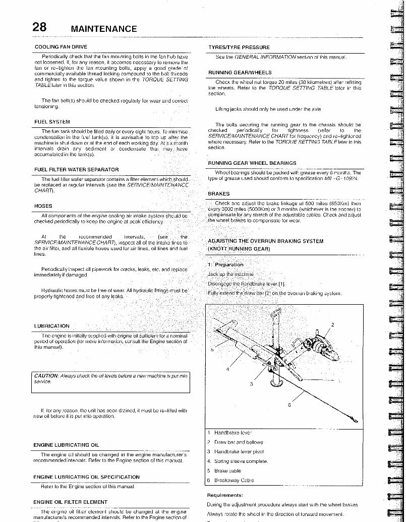
ADJUSTING THE OVERRUN BRAKING SYSTENI
(KNOTT RUNNING GEAR)
1: Preparation
Jack up the machine
Disengage the handbrake lever [1].
Fully extend the draw bar [2] on the overrun braking system.
LUBRICATION
The engine is initially supplied with engine oil sufficient for a nominal period of operation (for more information, consult the Engine section of this manual).
CAUTION: Always check the oil levels before a new machine is put into service.
lf, for any reason, the unit has been drained, it must be re-filled with new oil before it is put into operation.
ENGINE LUBRICATING OIL
The engine oil should be changed at the engine manufacturer's recommended intervals. Flefer to the Engine section of this manual.
ENGINE LUBRICATING OIL SPECIFICATION
Refer to the Engine section of this manual.
1 Handbrake lever
2 Draw bar and bellows
3 Handbrake lever pivot
4. Spring sleeve complete.
5 Brake cabie
6 Breakaway Cable
ENGINE OIL FILTER ELENIENT
The engine oil filter element should be changed at the engine manufacturer's recommended intervals. Refer to the Engine section of
Requirements:
During the adjustment procedure always start with the wheel brakes.
Always rotate the wheel in the direction of forward movement.
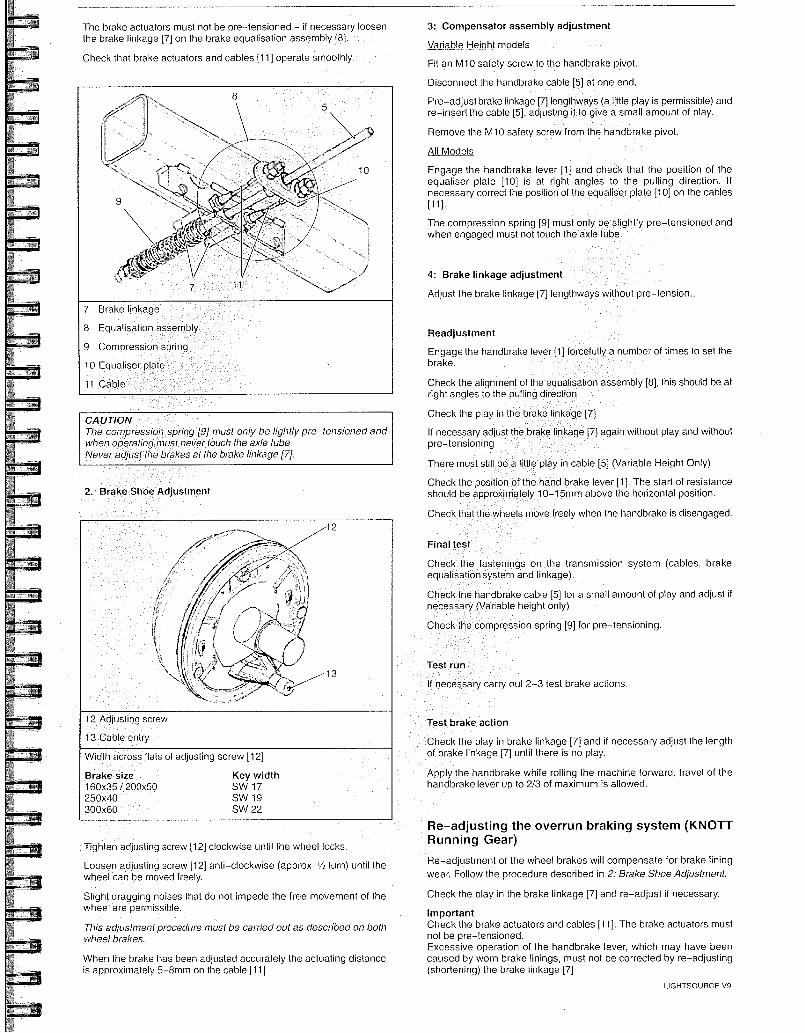
7 Brake linkage
8 Equalisation assembly
9 Compression spring
10 Equaliser plate
11 Cable
Test run
necessary carry out 2-3 test brake actions.
Test brake action
Check the play in brake linkage [7] and if necessary adjust the length of brake linkage [7] until there is no play.
Apply the handbrake while rolling the machine forward, travel of the handbrake lever up to 2/3 of maximum is allowed.
7: Brake linkage adjustment
Adjust the brake linkage [7] lengthways withou pre-tension..
The brake actuators must not be pre-tensioned - if necessary loosen the brake linkage [7] on the brake equalisation assembly [8].
Check that brake actuators and cables [11] operate smoothly.
CAUTION The compression spfing [9] must only be fightly pre-tensioned and when operating must never touch the axle tube. Never adjust the brakes at the brake linkage [7].
Final test
Check the fastenings on the transmission system (cables, brake equalisation system and linkage).
Check the handbrake cable [5] for a small amount of play and adjust if necessary (Variable height only)
Check the compression spring [9] for pre-tensioning.
3: Compensator assembly adjustment
Variable Height models
Fit an M10 safety screw to the handbrake pivot.
Disconnect the handbrake cable [5] at one end.
Pre-adjust brake linkage [7] lengthways (a little play is permissible) and re-insert the cable [5], adjusting it to give a small amount of play.
Remove the M10 safety screw from the handbrake pivot.
All Models
Engage the handbrake lever [1] and check that the position of the equaliser plate [10] is at right angles to the pulling direction. If necessary correct the position of the equaliser plate [10] on the cables [11].
The compression spring [9] must only be slightly pre-tensioned and when engaged must not touch the axle tube.
Readjustment
Engage the handbrake lever [1] forcefully a number of times to set the brake.
Check the alignment of the equalisation assembly [8], this should be at right angles to the pulling direction
Check the play in the brake linkage [7]
If necessary adjust the brake linkage [7] again without play and without pre-tensioning
There must still be a little play in cable [5] (Variable Height Only)
Check the position of the hand brake lever [1]. The start of resistance should be approximately 10-15mm above the horizontal position.
Check that the wheels move freely when the handbrake is disengaged.
12 Adjusting screw
13 Cable entry
Width across flats of adjusting screw [12]
Brake size
Key width 160x35 / 200x50
SW 17 250x40
SW 19 300x60
SW 22
Tighten adjusting screw [12] clockwise until the wheel locks.
Loosen adjusting screw [12] anti-clockwise (approx. 1/2turn) until the wheel can be moved freely.
Slight dragging noises that do not impede the free movement of the wheel are permissible.
This adjustment procedure must be carried out as described on both wheel btakes.
When the brake has been adjusted accurately the actuating distance is approximately 5-8rnm on the cable [11]
Re-adjusting the overrun braking system (KNOTT Running Gear)
Re-adjustment of the wheel brakes will compensate for brake lining wear. Follow the procedure described in 2: Brake Shoe Adjustment.
Check the play in the brake linkage [7] and re-adjust if necessary.
Important Check the brake actuators and cables [11]. The brake actuators must not be pre-tensioned. Excessive operation of the handbrake lever, which may have been caused by worn brake linings, must not be corrected by re-adjusting (shortening) the brake linkage [7]
LIGHTSOURCE V9
30 MAINTENANCE
Re-adjustment
The handbrake lever [1] should be engaged forcefully several times to set the braking system. Check the setting of the brake equalisation assembly [8], which should be at right angles to the pulling direction. Check the play in the brake linkage [7] again, ensuring that there is no play in the brake linkage and that it is adjusted without pre-tension Check the position of the hand brake lever [1], cable [5] (with little play) and the compression spring [9] (only slight pre-tension). The start of resistance of the handbrake lever should be approximately 10-15mm above the horizontal position.
Final test
Check the fastenings on the transmission system (cables, brake equalisation system and linkage)
Apply the handbrake while rolling the machine forward, travel of the handbrake lever up to 213 of maximum is allowed.
Check the handbrake cable [5] for a small amount of play and adjust if necessary (Variable height only)
Check the compression spring [9] for slight pre-tensioning.
CAUT1ON: Check the wheel nut torque 20 miles (30 kilomelres) after refitting the wheels (Refer to the TORQUE SETTING TABLE later in this section).
GENERAL CLEANING INSTRUCTIONS
Keeping the machine clean of any oil and dirt is recommended tor both appearance and maximum service life of the equipment. The frequency of cleaning will be dependent on local conditions and the severity and frequency of operation.
NOTE: Do not use high pressure water, steam or solvent on the exterior finish of the unit housing.
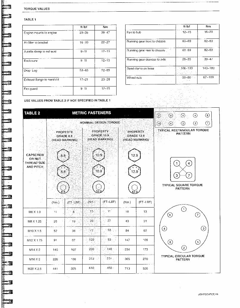
TABLE 2
CAPSCREW OR NUT
THREAD SIZE AND PITCH
PROPERTY GRADE 8.8
(HEAD MARKING)
x 8.8
PROPERTY GRADE 12.9
(HEAD MARKING)
x
12.9
TORQUE VALUES
TABLE 1
ft lbf Nm
Engine mounts to engine 29-35 39-47
Air filter to bracket 16-20 22-27
Autella clamp to exhaust 9-11 12-15
Enclosure 9-11 12-15
Drop Leg 53-63 72-85
Exhaust flange to manifold 17-21 23-28
Fan guard 9-11 12-15
USE VALUES FROM TABLE 2 IF NOT SPECIFIED IN TABLE 1
ft lbf Nm
Fan to hub 12-15 16-20
Running gear front to chassis 63-69 82-93
Running gear rear to chassis 63-69 82-93
Running gear drawbar to axle 29-35 39-47
Band clamp on hose 106- 33 143-180
Wheel nuts 50-80 67-109
(N ) (FT-LBF)
METRIC FASTENERS
NOMINAL DESIGN TORQUE
PROPERTY GRADE 10.9
(HEAD MARKING)
(FT-LBF) (Nm.) (FT-LBF)
M8 X 1.25
M10 X 1.5
M6 X 1.0
52
26
1
38
19
72
27
53
43
84
18
31
62
13
M12 X 1.75 91 67 93 147 109
M14 X 2 145 107 200 48 234 173
M16 X 2 226 166 313 231 365 270
TYPICAL RECTANGULAR TORQUE PATTERN
00
00 TYPICAL SQUARE TORQUE
PATTERN
TYPICAL CIRCULAR TORQUE PATTERN
LIGHTSOURCE V9
M20 X 2.5 441 325 610 450 713 526
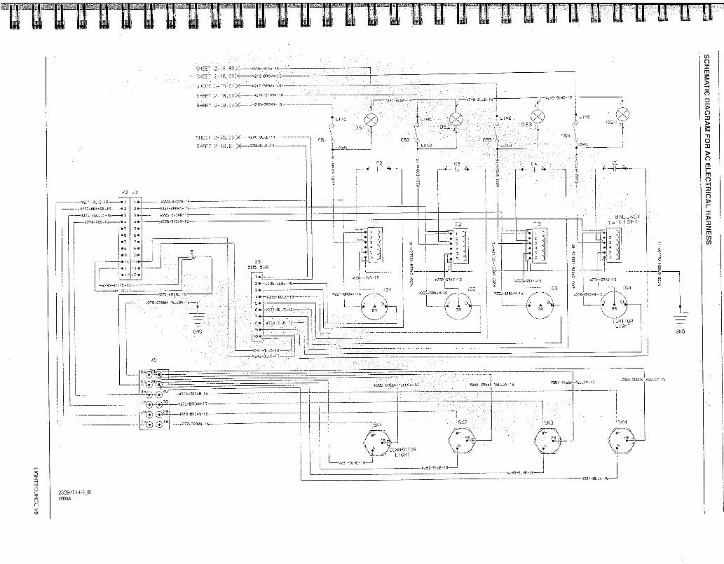
I eI2 5 5219 3LUE 15
LOAD 090 •
093
•
C3 2•
CS
T T3
BALLAS I 14 1GHT
4233 GRAY -15
51229000059016
L•Y
1153 w22
agt
9237 0110 5 16
I 02 5230-00045 16
ee
423 -5900-I6
4223 29018 IS
224 2878 19
922e 9130.44 10
5220 e9048 le
X3 EU5 EAR
1 ck.
2 •--5235-91_312-16
3 •
.4 4236-0L05-/5
•
6 •—'42 7
11270 0eE21 fELL 1
! GN I TOR I GHT
GND
El• 230- -1
0 290
5227 50 16
1 2 3
T I
02
C92
25'
SC
HE
MA
TIC
DIA
GR
AM
FO
R A
C E
LEC
TR
ICA
L HA
RN
ES
S
1, • J3
6271- 12LIJE-16 { • 1 1 •-
w272 0R960E-16--Le 2
9273-R5LLQ5-16---I-•, 3
—5274-020-16----- 1-• 4
*6
• 7
• e
• 9
1 I
I • 12
L0299-4e1T5-16
SHEET 2 29.,1cJ /2)(
E 1>< e BR
b600l 2 -
, 8, c]
512045
SHE 8, c) X 5215-39045- 1 9
SHEET 2 - 61
SHEET 2 - 1.8, I3 ‘,1,5239- 9LUE
053
1-/ 4288-00005 YELLOW-15
w2.96 -0 52117-CREEN- 01,16
0 - TELLO4 - EN
5 9 •
CONNECTOR I_ I GHT
1--4201-131.55 52312-6L31: 6
420, 3130 15 -1
g293 65175 '6
23294714 -3_B 10/08
6A
30E
1rIO
SI
HO
l1
9200 300 14 15
'2@-er,,"•:) '5 I 4273 090141 ,1 16
2 , „ • 42e5 13ROAN 15
SI "277 390148 '6
66
BLUE-1
282 3LUE 16
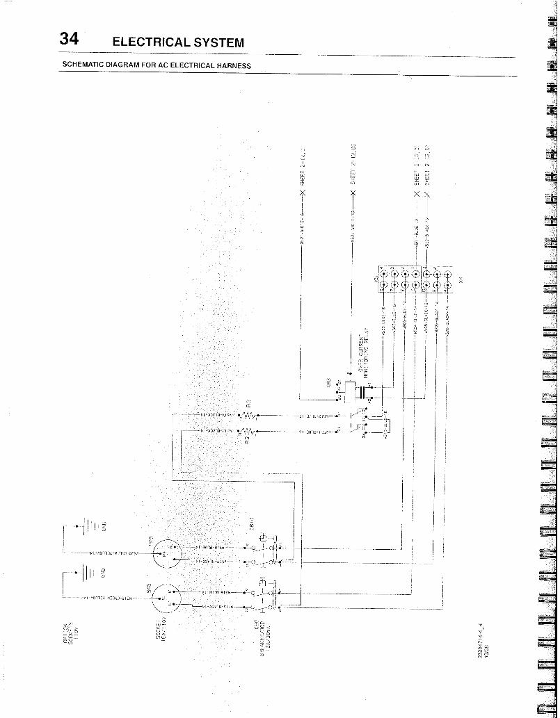
34 ELECTRICAL SYSTEM
SCHEMATIC DIAGRAM FOR AC ELECTRICAL HARNESS
7, (-■,) t L1,
z
z
LIJ F-
0 Z
•,-Wv t•
1:1,1 N321 0691
efl
t MOT11 6338.) 61g/1
[7- ‘.5 <
or,
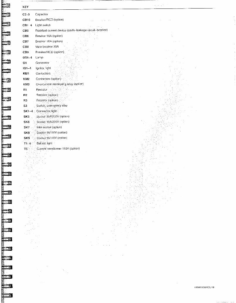
KEY
C2-5 Capacitor
CB10 Breaker/RCD (option)
CB1-4 Light switch
CB5 Residual current device (earth-leakage circuit-breaker)
CB6 Breaker 16A (option)
CB7 Breaker 16A (option)
CB8 Main breaker 30A
CB9 Breaker/RCD (option)
DS1 -4 Lamp
G1 Generator
IG1-4 Ignitor, light
KIVI1 Contactors
KI1/12 Contactors (option)
KIVI3 Overcurrent rnonitoring relay (option)
R1 Resisto
R2 Resistor (option)
R3 Resistor (option)
S3 Switch, ernergency stop
SK1 -4 Connector, light
SK5 Socket 16A/230V (option)
SK6 Socket 16AJ230V (option)
SK7 Inlet socket (option)
SK8 Socket 16/110V (option)
SK9 Socket 16/110V (option)
Ballast, light
CUlfrent transformer 110V (option)
LIGHTSOURCE V9
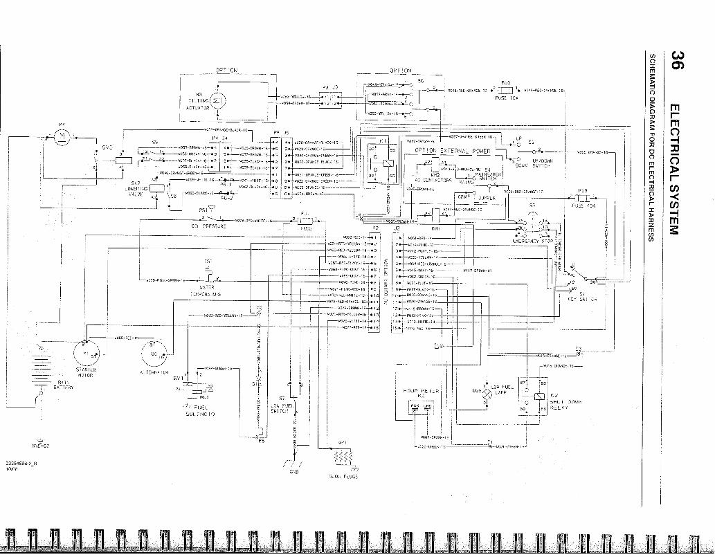
----4079-5114A-Grif
WATER
TEMPE0A1URE
44003 1200 VCLLO- 16
1
ARTER MOTOR
501
n,0E4-GREEN- 16— AL (E141A OR
2
,
HO , D
4-77 FUEL
500590 ID
BAT', -77- BATTERY
23284598-213 10/08
—wW17-903.41-15—
-327 trAN UP G: 0010,40- L____
. ■ 1 c2 , .---0 -
OPTION EXP, PKA'... POWER "----7 c, 2. 1.020-0041.0E-16 [...--. — -....3 — — _ ,
A 7, ,, l'.5-° yP4DEWN 2
----..---1 .. ,DC"
SW1 TCH 54043-REC-0440140L-16 54 1
-
502 L.I.J410545E5I EL CONTACIORS mA1N SWiTCH ,
2 ,
? • 1W0j0 FD-ORANC6-15 o
N' 1 3309E5 '
WD 5-500.-16 653
•
029 000050 1E
ORANGE-GREEN-1S-J
056000-GLACK-10--h
7ij•
1 •- -1:031-ORANCE-CREEN-16
80 "os- 000144: GROES
4,1-9033-OR45CE-15
6 e- -14034-6110AN 13
53
01 9. 7. I AD
.470 A"---• FA, 7
EMERGPIC3 S 0 O0 7g
F350 40A
.D
50
51 KEY WW 1FCR
SC
HE
MA
TIC
DIA
GR
AM
FO
R D
C E
LE
CT
RIC
AL
HA
RN
ES
S
1/11
31S
AS
1V
31}1
13313
57
LOW FUEL SW TEH
u- E6
;
G_CVA PLUGS
HDLIER 11E E 112
I 435 0117
'
9007-00096-16
L4022-1.0EE0-16 ., 021 GREEN 15
LOK FUEL 055
I ;11R
2F
F •
37
giVigieP C060150 7 gintr ,5940687 rt.ta? r 1402S.42
114
5V3 9050 8470,0 15- op4
,t WOSE 104046-10-,e3
W057 el ACK 16--• 2
A 4:058 ELACK 15 • 3 •
1 ,-10 40-0RAN0E-00EEN 1E
652 4050 ,,,,FTE 10-•=4---4--1,041 - ,11 TO - 10 ' F 1 , ,•
, -E3LACK - 15 LOWER P6-1 0062
ING1 1 I VAL ,‘, 0 i \, 58 014D60 -RLAD% - i s- _ 1
-2
I -,-•
OIL PRESSURE
P.517 61.11
2 RED WH:TE
FUSE
4 •-[—WC35-BA0RN-I G
3*- 6037-85060- 45-
2.-1-44C55-EL0C0-105
1 • BLACK-18—.7
• 1
--•6
-.e • s. *6
AUIO
51A
R1
OP
T IO
N
FU2 2 1
•••---140A6-06.3-0RANGE -46
FUSE 10A
'05D RED II e 1
1 00 RED VFL, 3,645 2re
RED 00.06 • 3
w006 9,■ 11"6-44 e
W057-RE0-8 , RCK-1E
-44060-7I04' CRA 0. 6
GRAY •7
6070 :01, 16 r. 4407 , I0K-RCD-16-7•D
44072-050 W,11 , 6-15-1-* 1
14 7: RED 0001,0E-16-ft IV
74 EIR0W0-16-k 12
6 75800 16 r. 3 I
RED 1 4 1-• 1 5-
4344 -pEo.-0001,GC-IE
,•--41001 RED
2* 494• 0414 1C
• ---4012-000PLE-16
4 •-6007- VELL,OW
5•.--0004-44E11-00000E 6
6*---4010-0005 16
6117 900414.15
7. 401- 2 317E00
--14023-1LUE-10
9 •---4017 OLACII-15
,
..._9020-011404E-16
, 2 •-•--0116-88390-16
i 3.--4015-P ,AK ,
4. 4.010 wilITE-1 ,4
1 5• 1:032-17:-.0-14
55
73 T1LTIN01,>_1),
ACTJATOR *I •
ON OP T !ON
,
1 I 3 2,3
FT,O4.9-YELLev-154-0 56
,.--1-.403-100L34-16—,.1 II '
12 1 2 • 11
0000 1C ,•-t-C
I 1_ 4050-VELLOO-15-•,-0
6048 ,rje 07'10E
6035 DRA , L, E-BLACK-IG P5
P 4 34
W006 570444
02 32
9040 ORANCE 10 -1
-1,016 ORANGF 16
51-tUT DOW6 es REL AN
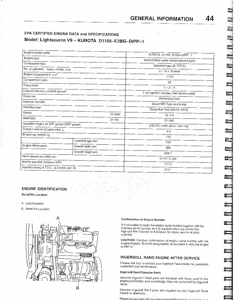
GENERAL INFORMATION 44
EPA CERTIFIED ENGINE DATA and SPECIFICATIONS
Model: Lightsource V9 - KUBOTA D1105-E2BG-DIPP-1
Engine model name KUBOTA D1105-E2BG-DIPP-1
Engine type Vertical inline water cooled diesel engine
Combustion type Spherical type (E-TVCS)
No, of cylinders - bore x stroke. mm 3 - 78 x 78.4mm
Engine displacement cm 3 1,123
Compression ratio 22
Firing order 1 - 2 - 3
Exhaust emission control system Fuel injection nozzles, fuel injector pump
Governor Mechanical type
Injection nozzles Bosch MD Type mini pump
Specified fuel Diesel fuel No2 (ASTM D975)
Starter (V-kW) 12-1.0 Alternator
(V-W) 12-360 Specified engine oil (API grade) (SAE grade)
(CD,CF) (10W-30 or 15W-40) Coolanl volume (Engine only) L
4.0 Engine dry weight kg
110
Overall length mm 549 Engine dimensions Overall width mm 396
Overall height mm 608.7 Valve clearance (cold) mm
0.145-0.185 Nozzle injection pressure MPa
13.73 Injection timing B.T.D.C. at 2.5mm cam lift
16.50
ENGINE IDENTIFICATION
Serial No Location
A. Label location
B. Serial No Location
Confirmation of Engine Number
It is advisable to quote the engine serial number together with the machine serial number, as it is required when you contact the Ingersoll Rand branch or distributor for repair, service or parts ordering.
CAUTION: Conduct confirmation of engine serial number with the engine stopped. To avoid being injured, do not check it, while the engine is still hot.
INGERSOLL RAND ENGINE AFTER SERVICE
Please feel free to contact your Ingersoll Rand dealer for periodical inspection and maintenance,
Ingersoll Rand Genuine Parts
Genuine Ingersoll Rand parts are identical with those used in the engine production, and accordingly, they are warrantecl by Ingersoll Rand.
Genuine Ingersoll Rand parts are supplied by your Ingersoll Rand branch or distributor.
Please ensure that onlv nonilino InnPrcnil P.nd nnric
If refueling is done from an oil drum directly, ensure that it has been kept stationary to allow any dust, sediment or water to settle at the bottom. Do not draw fuel direct from the bottom of the drum to prevent pickup of any settled foreign material.
Always fully fill the fuel tank. Drain the sedimented particles in the fuel tank frequently.
FUEL
Fuel Selection
The following properties are required of the diesel fuel:
Must be free from minute dust particles.
Must have adequate viscosity.
Must have high cetane value.
Must have high cetane value., (45 or greater)
Must have high fluidity at low temperature.
Must have low sulphur content.
Must have little residual carbon.
It is strongly advisable to use ASTM D975 No. 2D (the general automotive diesel engine purpose fuel oil) or equivalent which fully meets the above requirements.
Applicable Standard Recommendation
JIS (Japanese Industrial Standard) K2204 - 2
DIN (DEUTSCHE INDUSTRIE NORMEN) DIN 51601
SAE (Society of Automotive Engineers) Based on SAE-J-313C
NO. 2-D
BS (BRITISH STANDARD) Based on
BS/2869-1970
Class A-1 or A-2
ISO 8217 DMA
FUEL REQUIREMENTS
Notice: the fuel injection pump, injector or other parts of the fuel system and engine can be damaged if you use any fuel or fuel additive other than those specifically recommended by Ingersoll Rand.
NOTE: 1f any fuel other than the one specified is used, engine operation will be impaired Engine failure or malfunction tesulting from use of such improper fuel will not be warranted by Ingersoll Rand.
To help avo d fuel system or engine damage, please read the following:
Do not use diesel fuel which has been contaminated with engine oil. Besides causing engine damage, such fuel can also affect emission control. Before using any diesel fuel, check with the fuel supplier to see if the fuel has been mixed with engine oil.
Your engine is designed to use either Number 1-0 or Number 2-D diesel fuel. However, for better fuel economy, use Number 2-D diesel fuel whenever possible. At temperatures less than -7°C, (20°F), Number 2-D fuel may pose operating problems. At colder temperatures, use Number 1-D fuel (if available) or use a "winterized" Number 2-D (a blend of Number 1-D and Number 2-D). This blended fuel is usually called Number 2-0 also, but can be used in colder temperatures than Number 2-D fuel which has not been "winterized."
Check with the fuel supplier to be sure you get the properly blended
fuel.
NOTICE: Do not use home heating oil or gasoline in your diesel engine; either may cause engine damage.
Handling of the Fuel.
Any fuel containing dust particles or water might cause engine failure .
Therefore, the following must be observed.
Take care to protect the fuel from ingress of dust particles or water when filling the fuel tank.
Water in Fuel
During refueling, it is possible for water (and other contaminants) to be pumped into your fuel tank along with the diesel fuel. This can happen if a fuel provider does not regularly inspect and clean its fuel tanks, or receives contaminated fuel from its supplier(s). To protect your engine from contaminated fuel, there is a fuel filter system on the engine which allows you to drain excess water.
CAUTION: The water/diesel fuel mixture is flammable, and could be hot. To avoid personal injury and/or property damage, do not touch the fuel coming from the drain valve, and do not expose the fuel to open flames or sparks.
Be sure you do not overfill the fuel tank. Heat (such as from the engine) can cause the fuel to expand. If the tank is too full, fuel could be forced out. This could lead to a fire and the risk of personal injury and/or equipment damage.
Biocides In warm or humid weather, fungus and/or bacteria may form in diesel
fuel if there is water in the fuel.
NOTICE: Fungus or bacteria can cause fuel syslem damage by plugging the fuel lines
' fuel filters or injector. They can also cause fuel
system corrosion.
If fungus or bacteria has caused fuel system problems, you should have your authorized dealer correct these problems. Then, use a diesel fuel biocide to sterilize the fuel system (follow the biocide manufacturer's instructions). Biocides are available from your dealer, service stations, parts stores and other automotive places. See your authorized dealer for advice on using biocides in your area and for recommendationson which biocides you should use.
Smoke Suppressants
The use of a smoke suppressant additive is not allowed because of the greater possibility of stuck rings and valve failure, resulting from
excessive ash deposits.
LIGHTSOURCE V9
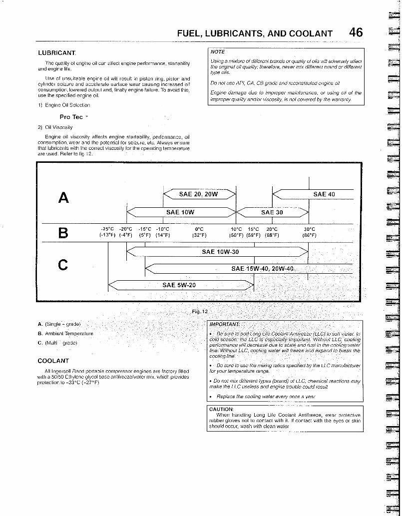
SAE lOW SAE 30
< SAE 20, 20W > SAE 40
-25°C -20°C -15°C -10°C 0°C 10°C 15°C 20°C (-13°F) (-4°F) (5°F) (14°F) (32°F) (50°F) (59°F) (68°F)
SAE 10W-30
SAE 15W-40, 20W-40
SAE 5W-20
30°C (86°F)
A. (Single grade)
B. Ambient Temperature
C. (Multi - grade)
FUEL, LUBRICANTS, AND COOLANT 46 LUBRICANT.
The quality of engine oil can affect engine performance, startability and engine life.
Use of unsuitable engine oil will result in piston ring, piston and cylinder seizure and accelerate surface wear causing increased oil consumption, lowered output and, finally engine failure. To avoid this, use the specified engine oil.
1) Engine Oil Selection
Pro Tec '
2) Oil Viscosity
Engine oil viscosity affects engine startability, performance, oil consumption, wear and the potential for seizure, etc. Always ensure that lubricants with the correct viscosity for the operating temperature are used. Refer to fig 12.
NOTE
Using a mixture of different brands or quality of olls will adversely affect the original oil quality; therefore, never mix different brand or different type oils.
Do not use API, CA, CB grade and reconstituted engine oil
Engine damage due to improper maintenance, or using oil of the improperquality andlor viscosity, is not covered by the warranty.
IMPORTANT:
• Be sure to add Long Life Coolant Antifreeze (LLC) to soft water In cold season, the LLC is especially important. Without LLC cooling performancewill decrease due to scale and rust in the cooling waler line. Without LLC, cooling water will freeze and expand to break the cooling line.
• Be sure to use the mixing ratios specified by the LLC manufacturer for your temperature range.
• Do not mix different types (brand) of LLC, chemical reactions may make the LLC useless and engine trouble could result
• Replace the cooling water every once a year
CAUTION: When handling Long Life Coolant Antifreeze, wear prolective
rubber gloves not to contact with it. If contact with the eyes or skin should occur, wash with clean water
COOLANT
All Ingersoll Rand portable compressor engines are factory filled with a 50/50 Ethylene glycol base antifreeze/water mix. which provides protection to -33°C (-27°F)
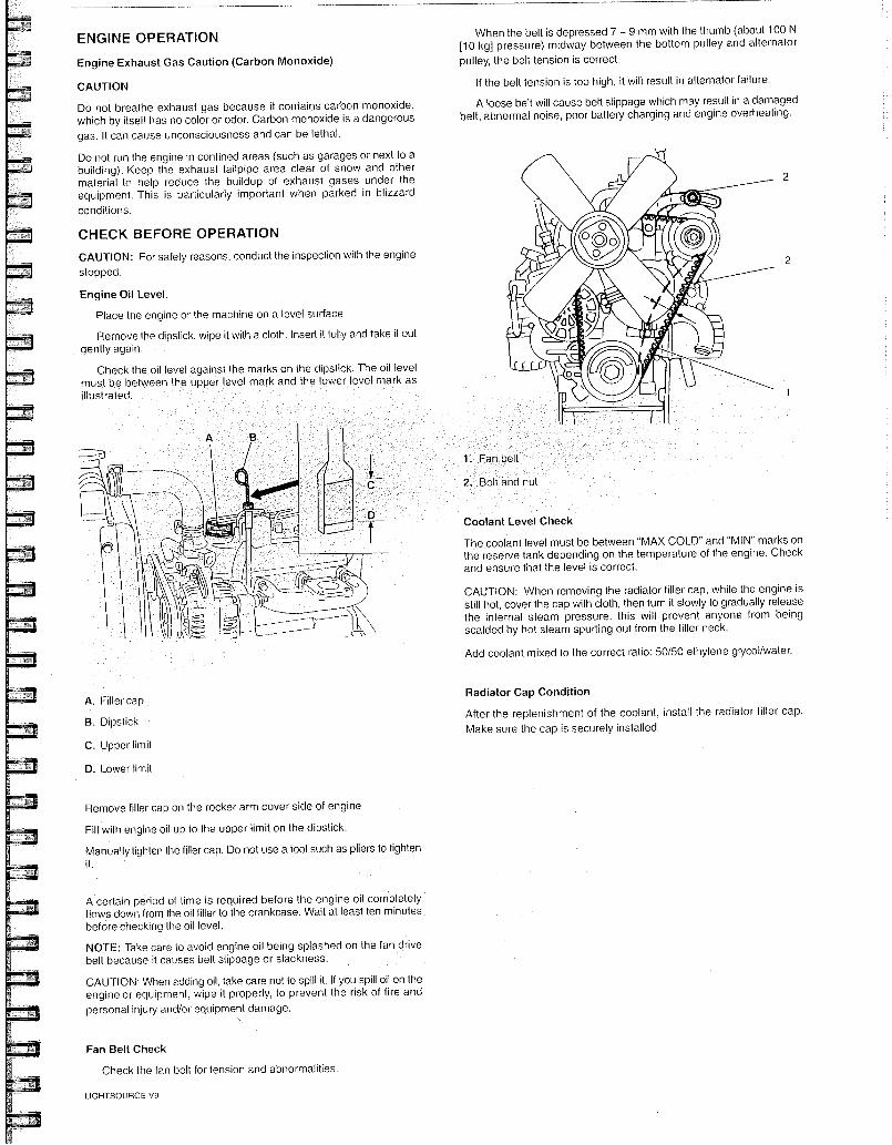
Fan belt
Bolt and nu
ENGINE OPERATION
Engine Exhaust Gas Caution (Carbon Monoxide)
CAUTION
Do not breathe exhaust gas because it contains carbon monoxide, which by itself has no color or odor. Carbon monoxide is a dangerous gas. It can cause unconsciousness and can be lethal.
Do not run the engine in confined areas (such as garages or next to a building). Keep the exhaust tailpipe area clear of snow and other material to help reduce the buildup of exhaust gases under the equipment. This is particularly important when parked in blizzard
conditions.
CHECK BEFORE OPERATION
CAUTION: For safety reasons, conduct the inspection with the engine
stopped.
Engine Oil Level.
Place the engine or the machine on a level surface
Remove the dipstick, wipe it with a cloth. Insert it fully and take it out gently again.
Check the oil level against the marks on he dipstick. The oil level must be between the upper level mark and the lower level mark as illustrated.
A. Filler cap
B. Dipstick
C. Upper limit
D. Lower limit
Remove filler cap on the rocker arm cover side of engine
Fill with engine oil up to the upper limit on the dipstick.
Manually tighlen the filler cap. Do not use a tool such as pliers to tighten
A certain period of time is required before the engine oil completely flows down from the oil filler to the crankcase. Wait at least ten minutes before checking the oil level.
NOTE: Take care to avoid engine oil being splashed on the fan drive belt because it causes belt slippage or slackness.
CAUTION: When adding oil, take care not to spill it. If you spill oil on the engine or equipment, wipe it properly, to prevent the risk of fire and personal injury and/or equipment damage.
Fan Belt Check
Check the fan belt for tension and abnormalities.
LIGHTSOUIRCE V9
When the belt is depressed 7 - 9 mm with the thumb (about 100 N [10 kg] pressure) midway between the bottom pulley and alternator pulley, the belt tension is correct.
If the belt tension is too high, it will result in alternator failure.
A loose belt will cause belt slippage which may result in a damaged belt, abnormal noise, poor battery charging and engine overheating.
Coolant Level Check
The coolant level must be between "MAX COLD" and "MIN" marks on the reserve tank depending on the temperature of the engine. Check and ensure that the level is correct.
CAUTION: When removing the radiator filler cap, while the engine is still hot, cover the cap with cloth, then turn it slowly to gradually release the internal steam pressure. this will prevent anyone from being scalded by hot steam spurting out from the filler neck.
Add coolant mixed to the correct ratio: 50/50 ethylene glycol/water.
Radiator Cap Condition
After the replenishment of the coolant, install the radiator filler cap. Make sure the cap is securely installed,
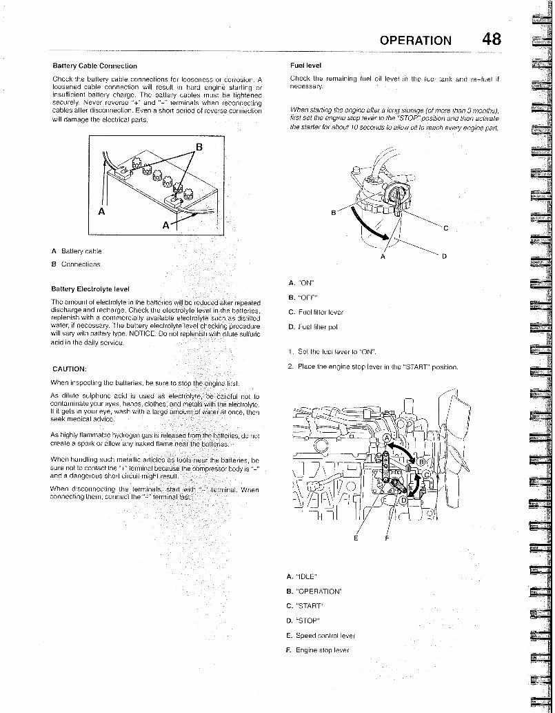
When disconnecting the terminals, start with "- erminal, When connecting them, connect the "-" terminal last.
Battery Cable Connection
Check the battery cable connections for looseness or corrosion. A loosened cable connection will result in hard engine starting or insufficient battery charge. The battery cables must be tightened securely. Never reverse "+" and terminals when reconnecting cables after disconnection. Even a short period of reverse connection will damage the electrical parts.
A Battery cable
B Connections
Battery Electrolyte level
The amount of electrolyte in the batteries will be reduced after repeated discharge and recharge. Check the electrolyte level in the batteries, replenish with a commercially available electrolyte such as distilled water, if necessary. The battery electrolyte level checking procedure will vary with battery type. NOTICE: Do not replenish with dilute sulfuric acid in the daily service.
CAUTION:
When inspecting the batteries, be sure to stop the engine first.
As dilute sulphuric acid is used as electrolyte, be careful not to contaminate your eyes, hands, clothes, and metals with the electrolyte. If it gets in your eye, wash with a large amount of water at once, then seek medical advice.
As highly flammable hydrogen gas is released from the batleries, do not create a spark or allow any naked flame near the batteries.
When handling such metallic articles as tools near the batteries, be sure not to contact the "+" terminal because the compressor body is and a dangerous short circuit might result.
Fuel level
Check the remaining fuel oil level in the fuel tank and re-fuel if necessary.
When starting the engine after a long storage (of more lhan 3 months), first set the engine stop lever to the 'STOP"position and then activate
the starter for about 10 seconds to allow oil to reach evety engine part.
A. "ON"
B. "OFF"
C. Fuel filter lever
D. Fuel filter pot
1. Set the fuel lever to "ON".
2. Place the engine stop lever in the `START" position.
A. "IDLE"
B. "OPERATION"
C. "START"
D. "STOP"
E. Speed control lever
F. Engine stop lever
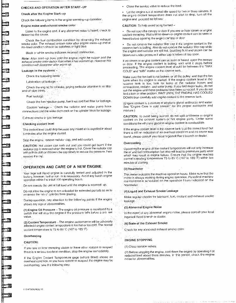
CHECKS AND OPERATION AFTER START-UP
Check after the Engine Start-up
Check the following items in the engine warming-up operation.
Engine noise and exhaust smoke color -
Listen to the engine and, if any abnormal notse is heard, check to determine the cause.
Check the fuel combustion condition by observing the exhaust smoke color. The exhaust smoke color after engine warm-up and at no-load condition should be colorless or light blue.
Black or white smoke indicates incorrect combustion.
Note: After start--up from cold the engine might be noisier and the exhaust smoke color datker lhan when it has wanned up. However this condition will disappear after warm up.
Leakage in the systems -
Check the following i
Lubrication oil leakage -
Check the engine for oil leaks, paying particular attention to oil filter and oil pipe joints.
Fuel leakage -
Check the fuel injection pump, fuel lines and fuel filter for leakage.
Coolant leakage - Check the radiator and water pump hose connections and the water drain cock on the cylinder block for leakage.
Exhaust smoke or gas leakage
Checking cooIant level
The coolant level could drop because any mixed air is expelled in about
5 minutes after the engine started.
Stop the engine, remove radiator cap, and add coolant.
CAUTION: Hot steam can rush out and you could get burnt if the radiator cap is removed when the engine is hot. Cover the radiator cap with a thick cloth and loosen the cap slowly to reduce the pressure, then
rernove the cap.
• Close the service valve to reduce the load.
• Let the engine run at normal idle speed for two or three minutes. If the engine coolant temperature does not start to drop, turn off the engine and proceed as follows:
CAUTION: To help avoid being burned -
• Do not open the canopy or door if you see or hear steam or engine coolant escaping. Wait until no steam or engine coolant can be seen or heard before opening the engine canopy or door.
• Do not remove the radiator filIer cap if the engine coolant in the reserve tank is boiling. Also do not remove the radiator filler cap while the engine and radiator are still hot. Scalding fluid and steam can be blown out under pressure if either cap is taken off too soon.
If no steam or engine coolant can be seen or heard, open the canopy or door. If the engine coolant is boiling, wait until it stops before proceeding. The engine coolant level should be between the "MAX COLD" and "MIN" marks on the reserve tank.
Make sure the fan belt is not broken, or off the pulley, and that the fan turns when the engine is started. If the engine coolant level in the reserve tank is low, look for leaks at the radiator hoses and connections, radiator, and water pump. If you find major leaks, do not run the engine until these problems have been corrected. If you do not find a leak or other problem, WAIT UNTIL THE ENGINE HAS COOLED DOWN then carefully add engine cootant to the reserve tank.
'(Engine coolant is a mixture of ethylene glycol antifreeze and water. See "Engine Care in cold season" for the proper antifreeze and
mixture.)
CAUTION: To avoid being burned, do not spill antifreeze or engine coolant on the exhaust system or hot engine parts. Under some conditions the ethyIene glycol in engine coolant is combustible.
If the engine coolant level in the reserve tank is at the correct level but there is still an indication of an overheat condition and no cause was found, please consuIt your local Ingersoll Rand branch or dealer.
Overcooling
Operating the engine at low coolant temperature will not only increase the oit and fuel consumption but also will lead to premature parts wear which may result in engine failure. Ensure that the engine reaches normal operating temperature 7510 85°C (167 to 185°F) within ten
minutes of starting.
(3) Hou rmeter
This meter indicates the machine operation hours. Make sure that the meter is always working during engine operation. Periodical machine maintenance is scheduled on the operation hours indicated on the
hourmeter.
(4) Liquid and Exhaust Smoke Leakage
Make regular checks for lubricant, fuel, coolant and exhaust smoke
leakage.
(5) Abnormal Engine Noise
In the event of any abnormal engine noise, please consult your local
Ingersoll Rand branch or dealer.
State of the Exhaust Smoke
Check for any abnormal exhaust smoke color.
ENGINE STOPPING
(1) Close service valves.
(2) Before stopping the engine, cool down the engine by operating it at reduced load about three minutes. In this period, check the engine noise for abnormalities.
OPERATION AND CARE OF A NEW ENGINE.
Your Ingersoll Rand engine is carefully tested and adjusted in the factory, however, further run-in is necessary. Avoid any harsh engine operation within the initial 100 operating hours.
Do not operate the unit at full load until the engine is warmed-uP.
Do not allow the engine to run unloaded for extended periods so as to minimise the risk of cylinder bore glazing.
During operation, pay attention to the following points if the engine shows any sign of abnormalities.
(1) Engine Oil Pressure - The engine oil pressure is monitored by a switch that will stop the engine if the pressure falls below a pre-set value.
(2) Coolant Temperature - The engine performance will be adversely affected if engine coolant temperature is too hot or too cold. The normal coolant temperature is 75 to 85°C (167 to 185°F).
Overheating
CAUTION:
If you see or hear escaping steam or have other reason to suspect there is a serious overheat condition, stop the engine immediately.
If the Engine Coolant Temperature gage (where fitted) shows an overheat condition, or you have reason to suspect the engine may be overheating, take the following step:
LIGHTSOURCE V9
OPERATION 50
LONG TERM STORAGE
If the equipment is to be out of operation for an extended period, it should be started at least once per week and run on load for about 15 minutes after it has reached normal operating temperature.
If this is not possible,
Do not drain the cooling water
Clean dust or oil from the engine extension
• Either fill completely or drain the fuel tank
• Grease accelerator joints and electrical connections
• Disconnect Ihe negative baltery terminal
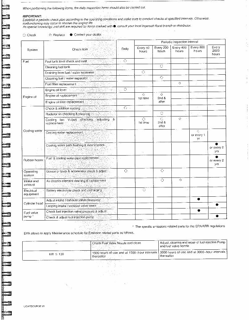
EPA allows to apply Maintenance schedule
* The specific emissions related parts for the EPA/ARB regulations
related parts as follows,
When performing the following items, the daily inspection items should also be carried out.
IMPORTANT: Establish a periodic check plan acconding to the operating conditions and make sure to conduct checks at specified intervals. Otherwise, malfunctioning may occur to shorlen the engine life. As special knowledge and skill are required for items marked with 0, consult your local Ingersoll Rand branch or distributor.
0: Check 0: Replace 0: Contact your deale
System Check item Daily
Periodic inspection interval
Every 50 hours
Every 200 hours
Every 400 hours
Every 800 hours
Every 2000 hours
Fuel Fuel tank level check and refill
Cleaning fuel tank 0
Draining from fuel / water separator 0
Cleaning fuel / water separator
Fuel filter replacement 0
Engine oil
Engine oil level
Engine oil replacement 0 lst time
0 2nd & after Engine oil filter replacement
Cooling water
Check & addition cooling
Radiator fin checking & cleaning 0
Cooling fan V-belt checking, ad us ing & replacement
0 1st time
0 2nd & after
Cooling water replacement 0 or every 1
yr
Cooling water path flushing & maintenance • or every 2
yrs
Rubber hoses Fuel cooling water pipe replacement •
or every 2 yrs
Operating system
Governor lever & accelerator check & adjust 0 0
intake and exhaust
Air cleaner element cleaning & replacement 0 0
Electrical equipment
Battery electrolyte check and recharging 0
Cylinder head Adjust intake / exhaust valve clearance
Lapp ng intake lexhaust valve seats •
Fuel valve pump *
Check fuel injection valve pressure & adjust 0
Check & adjust fuel injection pump •
- Check Fuel Valve Nozzle and clean Adjust, cleaning and repair of fuel injection Pump and fuel valve nozzle
kW 130 1500 hours of use and at 1500-hour intervals thereafter
3000 hours of use and at 3000-hour intervals thereafter
LIGHTSOURCE V9
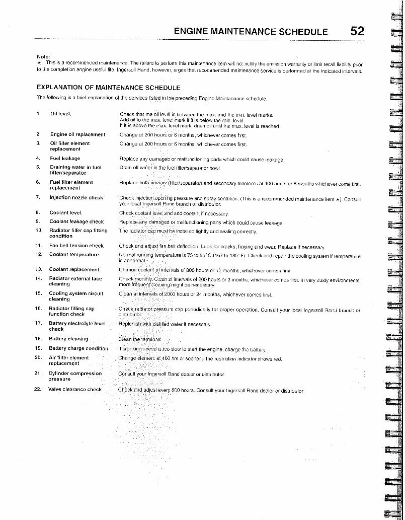
ENGINE MAINTENANCE SCHEDULE 52
Note:
* This is a recommended maintenance. The failure to perform this maintenance item will not nullify the emission warranty or limit recall liability prior to the completion engine useful life. Ingersoll Rand, however, urges that recommended maintenance service is performed al the indicated intervals.
EXPLANATION OF MAINTENANCE SCHEDULE
The following is a brief explanation of the services listed in the preceding Engine Maintenance schedule.
1. Oil level.
Check that the oil level is between the max. and the min, level marks. Add oil to the max. level mark if it is below the min, level. lf it is above the max. level mark, drain oil until the max. level is reached.
2. Engine oil replacement Change at 200 hours or 6 months, whichever comes first.
3. Oil filter element Change at 200 hours or 6 months, whichever comes first. replacement
4. Fuel leakage Replace any damaged or malfunctioning parts which could cause leakage.
5. Draining water in fuel Drain off water in the fuel filter/separator bowl. filter/separator.
6. Fuel filter element Replace both primary (filter/separator) and secondary elements at 400 hours or 6 months whichever come first. replacement
7. injection nozzle check
Check injection opening pressure and spray condition. (This is a recommended maintenance item ). Consult your local Ingersoll Rand branch or distributor.
8. Coolant level. Check coolant level and add coolant if necessary.
9. Coolant leakage check Replace any damaged or malfunctioning parts which could cause leakage.
10. Radiator filler cap fitting The radiator cap must be installed tightly and sealing correctly. condition
11. Fan belt tension check Check and adjust fan belt deflection. Look for cracks, fraying and wear. Replace if necessary.
12. Coolant temperature
Normal running temperature is 75 to 85°C (167 to 185°F). Check and repair the cooling system if temperature is abnormal.
13. Coolant replacement Change coolant at intervals of 800 hours or 12 months, whichever comes first.
14. Radiator external face Check monthly. Clean at intervals of 200 hours or 3 months, whichever comes first n very dusty environments, cleaning more frequent cleaning might be necessary.
15. Cooling system circuit Clean at intervals of 2000 hours or 24 months, whichever comes first. cleaning
16. Radiator filling cap Check radiator pressure cap periodically for proper operation. Consult your local Ingersoll Rand branch or function check distributor.
17. Battery electrolyte level Replenish with distilled water if necessary. check
18. Battery cleaning Clean the terminals
19. Battery charge condition If cranking speed is too slow to start the engine, charge the battery.
20. Air filter element Change element at 400 hrs or sooner if the restriction indicator shows red. replacement
21. Cylinder compression pressure
22. Valve clearance check Check and adjust every 800 hours. Consult your Ingersoll Rand dealer or distributor
Ingersoll Rand dealer or distributor
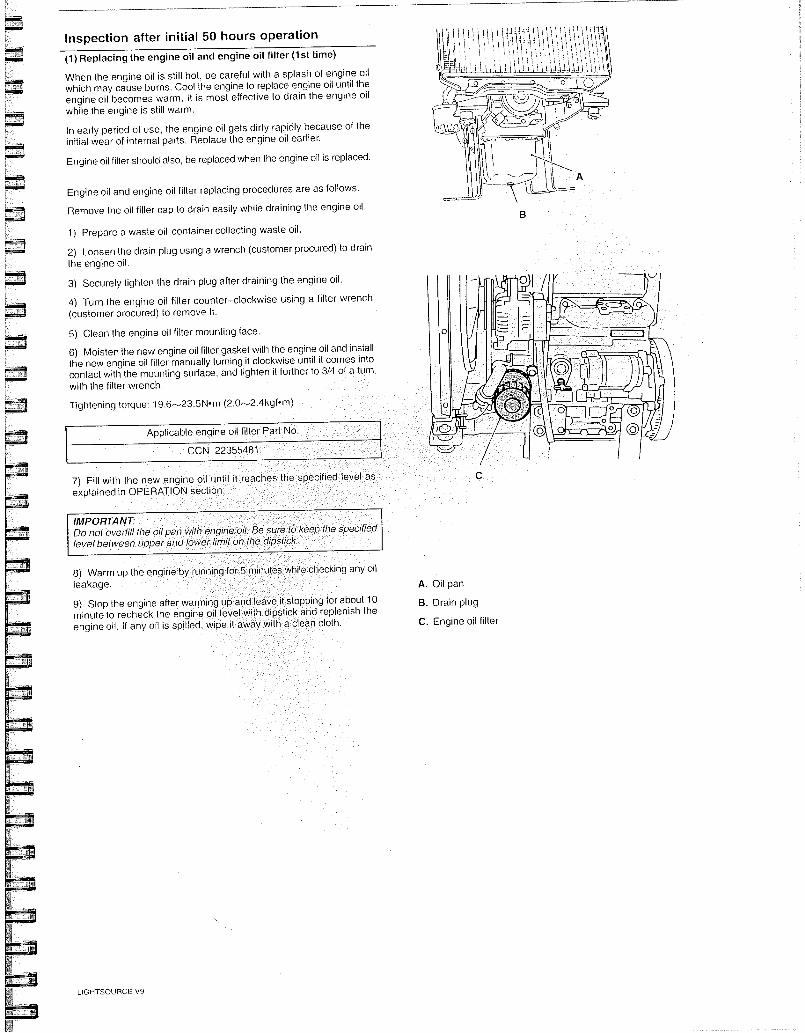
Inspection after initial 50 hours operation
(1) Replacing the engine oil and engine oil filter (1st time)
When the engine oil is still hot, be careful with a splash of engine oil which may cause burns. Cool the engine to replace engine oil until the engine oil becomes warm. It is most effective to drain the engine oiI while the engine is still warm.
In early period of use, the engine oil gets dirty rapidly because of the initial wear of internal parts. Replace the engine oil earlier.
Engine oil filter should also, be replaced when the engine oil is replaced.
Engine oil and engine oil filter replacing procedures are as follows.
Remove the oil (iller cap to drain easily while draining the engine oil.
1) Prepare a waste oil container collecting waste oil.
2) Loosen the drain plug using a wrench (customer procured) to drain the engine oil.
3) Securely tighten the drain plug after draining the engine oiI.
4) Turn the engine oil fitter counter-clockwise using a filter wrench (customer procured) to remove It.
5) Clean the engine oil filter mounting face.
6) Moisten the new engine oil filter gasket with the engine oil and install the new engine oil filter manually turning it clockwise until it comes into contact with the mounting surface, and tighten it further to 3/4 of a turn with the filter wrench.
Tightening torque: 19.6-23.5N-m (2.0-2.4kgf.m)
Applicable engine oil filter Part No.
CCN 22355481
7) Fill with the new engine oil until it explained in OPERATION section.
IMPORTANT Do not overfill the oil pan with engine oit Be sure to keep the specified level between upper and lower lirnit on the dipstick.
8) Warm up the engine by leakage.
9) Stop the engine after warming up and leave it stopping for about 10 minute to recheck the engine oil leveI with dipstick and replenish the engine oiI. If any oit is spilled, wipe it away with a clean cloth.
running inutes while checking any oil
A. Oil pan
B. Drain plug
C. Engine oil filter
LIGHTSOURCE V9
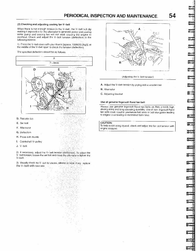
D. Radiator fan
E. Set bolt
Alternator
G. Deflection
H. Press with thumb
I. Crankshaft V-pulley
J. V-belt
7-9mm
PERIODICAL INSPECTION AND MAINTENANCE. 54 (2) Checking and adjusting cooling fan V-belt
When there is not enough tension in the V-belt, the V-belt will slip making it impossible for the alternator to generate power and cooling water pump and cooling fan will not work causing the engine to overheat. Check and adjust the V-belt tension (deflection) in the following manner.
1) Press the V-belt down with your thumb [approx. 100N(10.2kgf)] at the middle of the V-belt span to check the tension (deflection).
The specified deflection should be as follows.
2) If necessary, adjust the V-belt tension (deflection). To adjust the V-belt tension, loosen the set bolt and move the alternator to tighten the V-belt.
(Adjusting the V-belt tension)
A. Adjust the V-belt tension by prying with a wooden bar
B. Alternator
C. Adjusting bracket
Use of genuine Ingersoll Rand fan belt
Always use genuine Ingersoll Rand fan belts as they provide high driving ability and long operating durability. Use of non-lngersoll Rand fan belts could result in premature belt wear or belt elongation leading to engine overheating or excessive belt noise.
CAUTION: To help avoid being injured, check and adjust the fan belt tension with engine stopped.
3) Visually check the V-belt for cracks, oiliness or wear. If any, , replace the V-belt with new one.
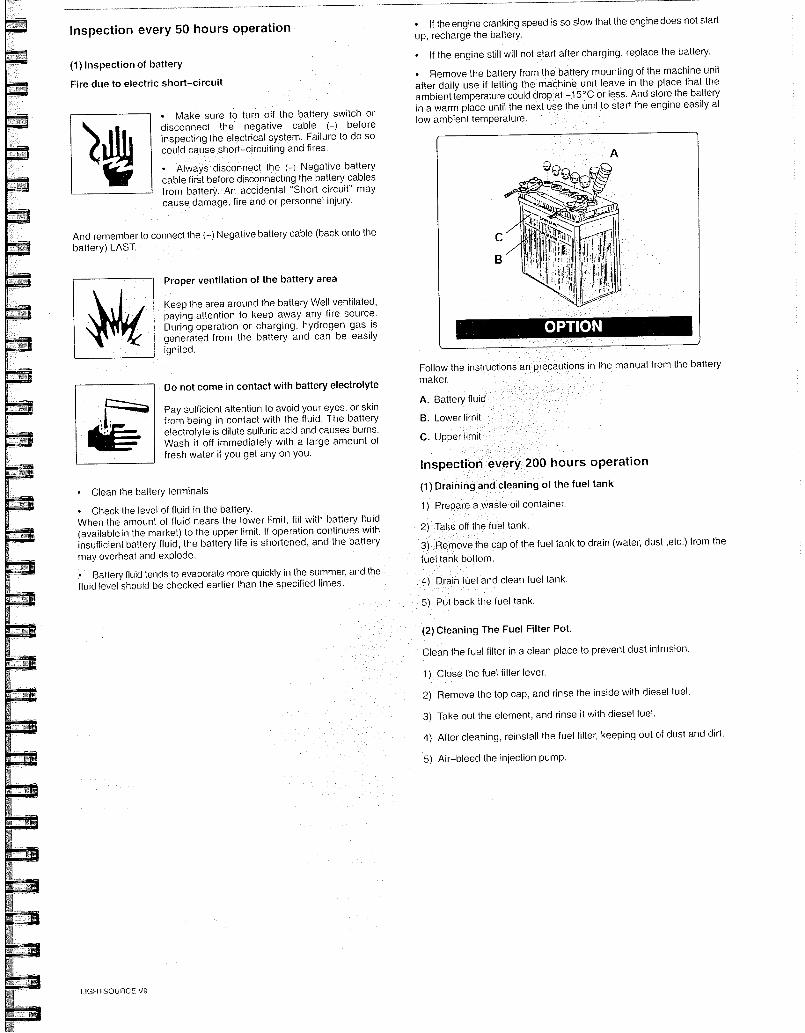
Follow the instructions an maker.
A. Battery fluid
B. Lower limi
C. Upper limit
recautions in the manual from the battery
Inspection every 50 hours operation
(1) Inspection of battery
Fire due to electric short-circuit
• Make sure to turn off the battery switch or disconnect the negative cable (-) before inspecting the electrical system. Failure to do so could cause short-circuiting and fires.
• Always disconnect the (-) Negative battery cable first before disconnecting the battery cables from battery. An accidental "Short circuit" may cause damage, fire and or personnel injury.
And remember to connect the (-) Negative battery cable (back onto the battery) LAST.
P oper ventilation of the battery area
Keep the area around the battery Well ventilated, paying attention to keep away any fire source. During operation or charging, hydrogen gas is generated from the battery and can be easily ignited.
Do not come in contact with battery electrolyte
Pay sufficient attention to avoid your eyes. or skin from being in contact with the fluid. The battery electrolyte is dilute sulfuric acid and causes burns. Wash it off immediately with a large amount of fresh water if you get any on you.
• Clean the battery terminals
• Check the level of fluid in the battery. When the amount of fluid nears the lower limit, fill with battery fluid (available in the market) to the upper limit. If operation continues with insufficient battery fluid, the battery life is shortened, and the battery may overheat and explode.
• Battery fluid tends to evaporate more quickly in the summer, and the fluid level should be checked earlier than the specified limes.
• If the engine cranking speed is so slow that the engine does not start up, recharge the battery.
• If the engine still will not start after charging, replace the battery.
• Remove the battery from the battery mounting of the machine unit after daily use if letting the machine unit leave in the place that the ambient temperature could drop at -15°C or less. And store the battery in a warm place until the next use the unit to start the engine easily at low ambient temperature.
Inspection every 200 hours operation
(1) Draining and cleaning of the fuel tank
1) Prepare a waste oil container.
2) Take off the fuel tank.
3) Remove the cap of the fuel tank to drain (water, dust ,etc.) from the
fuel tank bottom.
4) Dra n fuel and clean fuel tank.
5) Put back the fuel tank.
(2) Cleaning The Fuel Filter Pot.
Clean the fuel filter in a clean place to prevent dust intrusion.
1) Close the fuel filter lever.
2) Remove the top cap, and rinse the inside with diesel fuel.
3) Take out the element, and rinse it with diesel fuel.
4) After cleaning, reinstall the fuel filter, keeping out of dust and dirt.
5) Air-bleed the injection pump.
LIGHTSOURCE V9
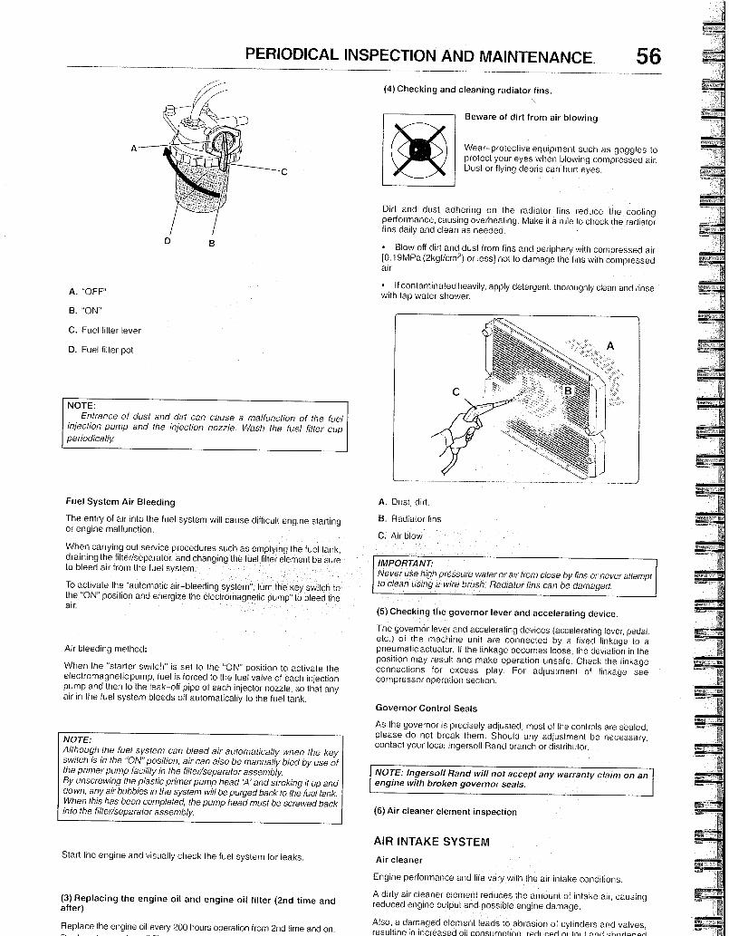
Beware of dirt from air blowing
Wear-protective equipment such as goggles to protect your eyes when blowing compressed air. Dust or flying debris can hurt eyes.
PERIODICAL INSPECTION AND MAINTENANCE. 56
A. "OFF"
B. "ON"
C. Fuel filter lever
D. Fuel filter pot
NOTE: Entrance of dust and dirt can cause a malfunction of the fuel
injection pump and the injection nozzle. Wash the fuel filler cup periodically
Fuel System Air Bleeding
The entry of air into the fuel system will cause difficult engine starting or engine malfunction.
When carrying out service procedures such as emptying the fuel tank, draining the filter/separator, and changing the fuel filter element be sure to bleed air from the fuel system.
To activate the "automatic air-bleeding system", turn the key switch to the "ON" position and energize the electromagnetic pump' to bleed the air.
Air bleeding method:
When the "starter switch" is set to the "ON" position to activate the electromagnetic purnp, fuel is forced to the fuel valve of each injection pump and then to the leak-off pipe of each injector nozzle, so that any air in the fuel system bleeds off automatically to the fuel tank.
NOTE: Although the fuel system can bleed air automatically when the key switch is in the "ON" position, air can also be manually bled by use of the primer pump facility in the filter/separator assembly. By unscrewing the plastic primer pump head 'A' and stroking it up and down, any air bubbles in the system will be purged back to the fuel tank. When this has been completed, the pump head must be screwed back into the filter/separator assembly.
Start the engine and visually check the fuel system for leaks.
(3) Replacing the engine oil and engine oil filter (2nd time and after)
Replace the engine oil every 200 hours operation from 2nd time and on.
(4) Checking and cleaning radiator fins.
Dirt and dust adhering on the radiator fins reduce the cooling performance, causing overheating. Make it a rule to check the radiator fins daily and clean as needed.
• Blow off dirt and dust from fins and periphery wilh cornpressed air [0.19MPa (2kgf/cm 2) or less] not to damage the fins with compressed air.
• If contaminatedheavily, apply detergent, thoroughly clean and rinse with tap water shower.
(5) Checking the governor lever and accelerating device.
The governor lever and accelerating devices (accelerating lever, pedal. etc.) of the machine unit are connected by a fixed linkage to a pneumatic actuator. If the linkage becomes loose, the deviation in the position may result and make operation unsafe. Check the linkage connections for excess play. For adjustment of linkage see compressor operation section.
Governor Control Seals
As the governor is precisely adjusted, most of the controls are sealed, please do not break them. Should any adjustment be necessary, contact your local Ingersoll Rand branch or distributor.
NOTE: Ingersoll Rand will not accept any warranty claim on an engine with broken governor seals.
(6) Air cleaner element inspection
AIR INTAKE SYSTEM
Air cleaner
Engine performance and life vary with the air intake conditions.
A dirty air cleaner element reduces the amount of intake air, causing reduced engine output and possible engine damage.
Also, a damaged element leads to abrasion of cylinders and valves, resultina in increased oil const jmnt.nn rprii irpri riitni and chnri.n.d
IMPORTANT: Never use high pressure waterorair from close by fins or never attempt to clean using a wire brush. Radiator fins can be damaged.
A. Dust, dirt.
B. Radiator fins
C. Air blow
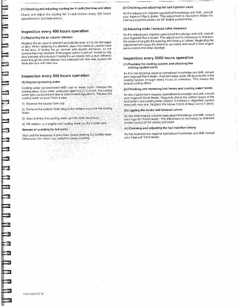
(2) Checking and adjusting the fuel injection valve
As the adjustment requires specialized knowledge and skill, .consult your Ingersoll Rand dealer. This adjustment is needed to obtain the optimum injection pattern for full engine performance.
(1) Checking and adjusting cooling fan V-belt (2nd time and after)
Check and adjust the cooling fan V-belt tension every 200 hours
operation from 2nd time and on.
Inspection every 400 hours operafion
(1) Replacing the air cleaner element
Replace the air cleaner element periodically even if it is not damaged or dirty. When replacing the element, clean the inside air cleaner case at the time. If having the air cleaner with double elements, do not remove the inner element. If the engine output is still not recover (or the dust indicator still actuates if having the air cleaner with a dust indicator) even though the outer element has replaced with new one, replace the inner element with new one.
Inspection every 800 hours operation
(1) Replacing cooling water
Cooling water contaminated with rust or water scale -reduces the cooling effect. Even when antifreeze agent (LLC) is mixed, the cooling water gets contaminated due to deteriorated ingredients. Replace the cooling water at least Once a year.
1) Remove the header tank cap
2) Remove the radiator drain plug o water .
3) After draining the cooling water, put the drain plug hack.
4) Fill radiator and engine with cooling water via the header tank.
Beware of scalding by hot water
Wait until the temperature goes down before draining the Cooling water. Otherwise, hot water may splash to cause scalding.
(3) Adjusting intake / exhaust valve clearance
As this adjustment requires specialized knowledge and skill, consult your Ingersoll Rand dealer. The adjustment is necessary to maintain the correct timing for the opening and closing of valves. Neglecting the adjustmentwill cause the engine to run noisily and result in poor engine performance and other damage.
Inspection every 2000 hours operation
(1) Flushing the cooling system and checking the cooling system parts
As this maintenance requires specialized knowledge and skill, consult your Ingersoll Rand dealer. Rust and water scale will accumulate in the cooling system through many hours of operation. This lowers the engine cooling effect.
(2) Checking and replacing fuel hoses and cooling water hoses
As this maintenance requires specialized knowledge and skill, consult your Ingersoll Rand dealer. Regularly check the rubber hoses of the fuel system and cooling water system. If cracked or degraded, replace them with new one. Replace the rubber hoses at least every 2 years.
(3) Lapping the intake and exhaust valves
As this maintenance requires specialized knowledge and skill, consult your Ingersoll Rand dealer. The adjustment is necessary to maintain proper contact of the valves and seats.
(4) Checking and adjusting the fuel injection timing
As this maintenance requires specialized knowledge and skill, consult your Ingersoll Rand dealer.
the radiator and drain the cooling
LIGHTSOURCE V9
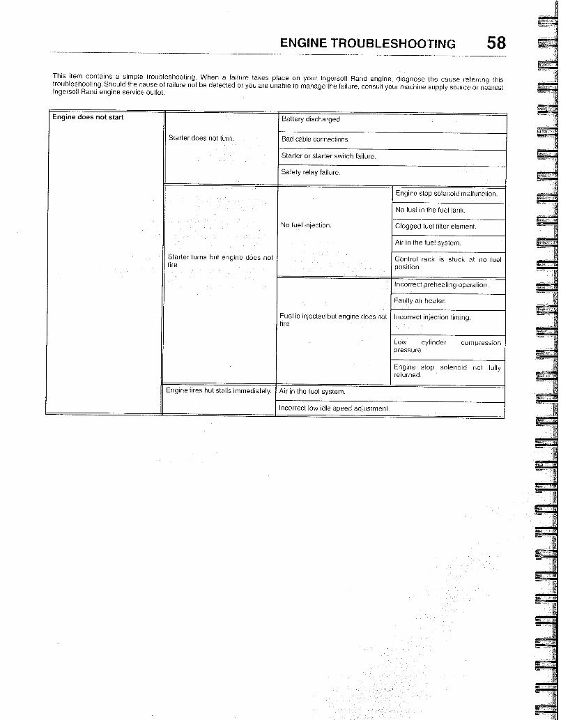
ENGINE TROUBLESHOOTING 58
This item contains a simple troubleshooting. When a failure takes place on your Ingersoll Rand engine, diagnose the cause referring this troubleshooting.Should the cause of failure not be detected or you are unable to manage the failure, consult your machine supply source or nearest Ingersoll Rand engine service outlet.
Engine does not start
Starter does not turn.
Battery discharged
Bad cable connections.
Starter or starter switch failure.
Safety relay failure.
Starter turns but engine does not fire.
No tuel injection.
Engine stop solenoid mal unction.
No fuel in the fuel tank.
Clogged fuel filter element.
Air in the fuel system.
Control rack is stuck at no fuel position.
Fuel is injected but engine does not fire.
Incorrect preheating operation.
Faulty air heater.
Incorrect injection tinling.
Low cylinder compression pressure.
Engine stop solenoid not fully returned.
Engine fires but stalls immediately. Air in the fuel system.
Incorrect low idle speed adjustment.
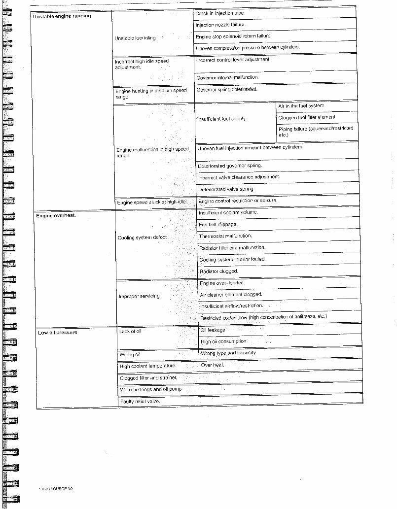
Cooling system defect
Improper servicing
Unstable engine running Crack in injection pipe.
Injection nozzle failure.
Engine stop soleno d return failure.
Uneven compression pressure between cylinders.
Unstable low idling
Incorrect high idle speed adjustment.
Incorrect control lever adjustment.
Governor internal malfunction.
Engine hunting in medium speed range.
Governor spring deteriorated.
Air in the fuel system
Clogged fuel filter element
Piping failure (squeezed/restricted etc.)
Uneven fuel injection amount between cylinders.
Deteriorated governor spring.
Incorrect valve clearance adjustment.
Deteriorated valve spring.
Insufficient fuel supply.
Engine malfunction in high speed range.
Engine speed stuck at high idle. Engine control restriction or seizure.
Engine overheat. Insufficient coolant volume.
Fan belt slippage.
Thermostat malfunction.
Radiator filler cap malfunction.
Cooling system interior fouled.
Radiator clogged.
Engine over-loaded.
Air cleaner element clogged.
Insufficient airflow/restriction.
Restricted coolant flow (high concentration of antifreeze, etc.)
Lack of oil Oil leakage Low oil pressure
High oil consumption
Wrong type and viscosity. Wrong oil
High coolant temperature Over heat.
Clogged filter and strainer.
Worn bearings and oil pump.
Faulty relief valve.
LIGHTSOURCE V9
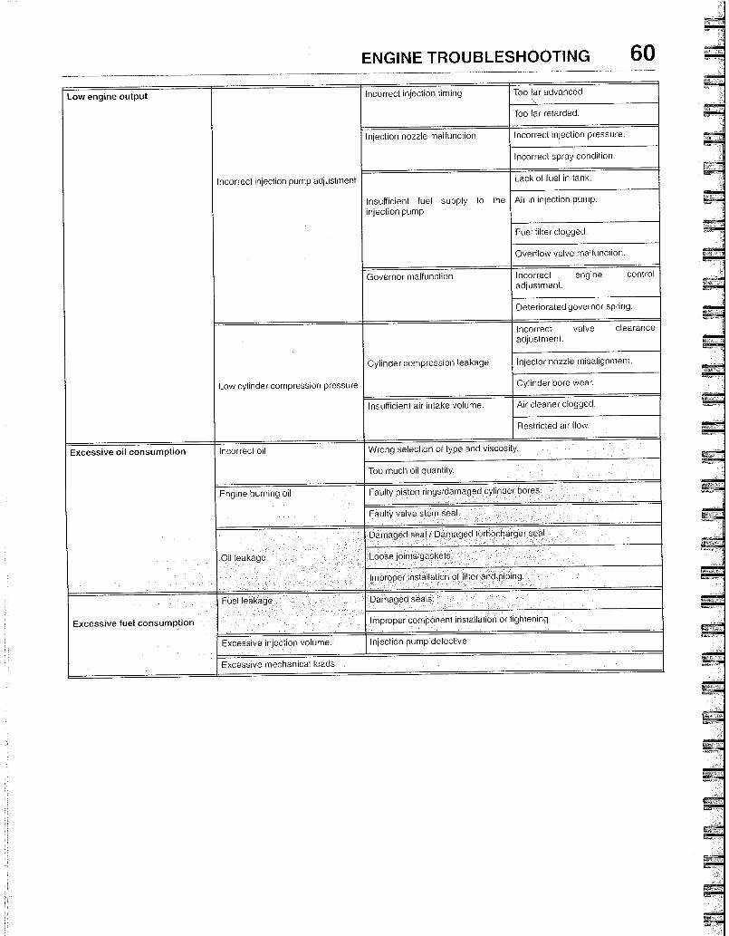
ENGINE TROUBLESHOOTING 60
Low engine output Incorrect injection timing Too far advanced.
Too far retarded.
Incorrect injection pump adjustment
Injection nozzle malfunction Incorrect injection pressure.
Incorrect spray condition.
Insufficient fuel supply to the injection pump
Lack of fuel in tank.
Air in injection pump.
Fuel filter clogged.
Overflow valve malfunction.
Governor malfunct on Incorrect engine control adjustment.
Deterioratedgovernor spring.
Low cylinder compression pressure
Cylinder compression leakage
Incorrect valve clearance adjustment.
Injector nozzle misalignment.
Cylinder bore wear.
Insufficient air intake volume. Air cleaner clogged.
Restricted air flow.
Excessive oil consumption Incorrect oil Wrong selection of type and viscosity.
Too much oil quantity.
Engine burning oil Faulty piston rings/damaged cylinder bores.
Faulty valve stem seal.
Oil leakage
Damaged seal / Damaged turbocharger seal
Loose joints/gaskets.
Improper installation of filter and piping.
Excessive fuel consumption
Fuel leakage Damaged seats.
Improper component installation or tightening.
Excessive injection volume. Injection pump defective.
Excessive mechanical loads
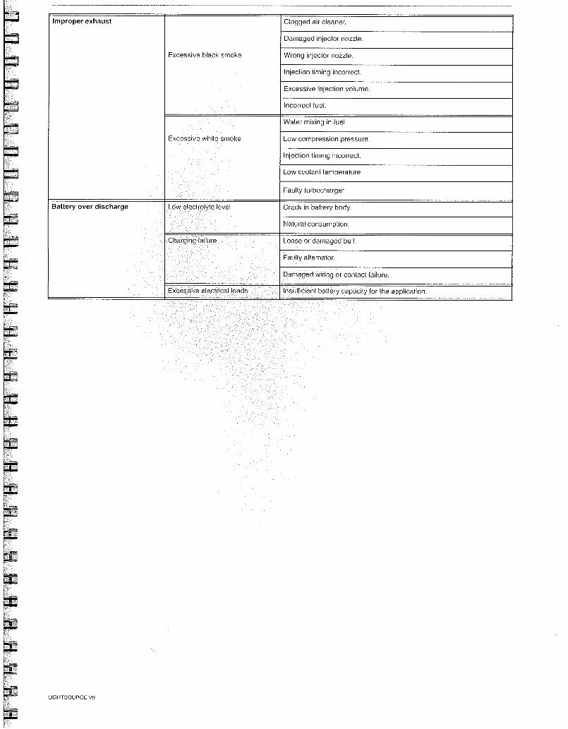
Improper exhaust
Excessive black smoke
Clogged air cleaner.
Damaged injector nozzle.
Wrong injector nozzle.
Injection timing incorrect.
Excessive injection volume.
lncorrect fuel.
Excessive white smoke
Water mixing in fuel
Low compression pressure
Injection timing incorrect.
Low coolant temperature
Faulty turbocharger
Battery over discharge Low electrolyte level Crack in battery body.
Natural consumption.
Charging failure Loose or damaged belt.
Faulty alternator.
Damaged wiring or contact failure.
Excessive electrical loads Insufficient battery capacity for the application.
LIGHTSOURCE VS


![cosmari [Sola lettura] [modalit compatibilit ]) · rsu porta a porta system mechanical biological treatment recovery bio gas landfill recovery multi-material paper porta a porta system](https://img.pdfslide.us/doc/110x75/5e3da4aaace15f78c848e948/cosmari-sola-lettura-modalit-compatibilit-rsu-porta-a-porta-system-mechanical.jpg)