Embed Size (px)
Citation preview
User guide and maintenance manual
DDOOOOSSAANN
EEnnggiinnee
PP112266
PS-MMG0717-E1B
Operation & Maintenance Manual
GENERATOR DIESEL ENGINE
DE12T POULS
P126TI-1 P126TI P126TI- Ⅱ
65.99897-8078A
DE12T/P126TI Operation and Maintenance Manual
Printed in Sep. 2008 PS-MMG0715-E1B
FOREWORD This maintenance manual is designed to serve as a reference for DOOSAN Heavy Industries Ltd's (here after DOOSAN’s) customers and distributors who wish to gain basic product knowledge on DOOSAN's DE series generator diesel engines (DE12T and POLUS P126TI) These economical and high-performance diesel engines (6 cylinders, 4 strokes, in-line, direct injection type) have been so designed and manufactured to be used for the generator application. They meet all the requirements such as low noise, fuel economy, high engine speed, and durability. To maintain the engine in optimum condition and retain maximum performance for a long time, CORRECT OPERATION and PROPER MAINTENANCE are essential.
In this manual, the following symbols are used to indicate the type of service operations to be performed.
Removal Adjustment Installation Cleaning Disassembly Pay close attention-Important Reassembly Tighten to specified torque Reassembly Use special tools of manufacturer's Directional Indication Lubricate with oil Inspection Lubricate with grease Measurement During engine maintenance, please observe following instructions to prevent environmental damage;
Take old oil to an old oil disposal point only. Ensure without fail that oil and diesel fuel will not get into the sea or rivers and canals or the ground. Treat undiluted anti-corrosion agents, antifreeze agents, filter element and cartridges as special waste. The regulations of the relevant local authorities are to be observed for the disposal of spent
coolants and special waste.
If you have any question or recommendation in connection with this manual, please do not hesitate to contact our head office, dealers or authorized service shops near by your location for any services.
For the last, the content of this maintenance instruction may be changed without notice for some quality improvement. Thank you.
Doosan Infracore Co., Ltd. Jan. 2008
DE12T/P126TI Operation and Maintenance Manual
Printed in Sep. 2008 PS-MMG0715-E1B
CONTENTS
1. Safety Regulations & Engine specifications
1.1. Safety Regulations 1 1.2. Engine Specification 7 1.3. Engine Assembly 8
2. Technical Information
2.1. Engine Model and Serial Number 12 2.2. Engines Characteristic 13 2.3. Troubleshooting 35 2.4. Operation Tip 45
3. Disassembly and Reassembly of Major Components
3.1. Disassembly 47 3.2. Inspection 61 3.3. Reassembly 79
4. Commissioning and Operation 4.1. Preparations 103 4.2. Breaking-in 103 4.3. Inspections after Starting 105 4.4. Operation in Winter Time 106 4.5. Tuning the Engine 107 4.6. Maintenance and Care 107 4.7. Cooling System 110 4.8. Adjustment of Valve Clearance 112 4.9. Fuel System 113 4.10. Injection Nozzle Maintenance 116
5. Maintenance of Major Components
5.1. Fuel Injection Pump 118 5.2. Cooling System 152 5.3. Lubricating System 156 5.4. Turbocharger 160 5.5. Air Intake System 169 5.6. V-belts 172
6. Special Tool List 174
Appendix 176
DE12T/P126TI Operation and Maintenance Manual
Printed in Sep. 2008 PS-MMG0715-E1B
1. Safety Regulations & Engine Specifications 1.1. Safety Regulations 1.1.1. General notes
Day-to-day use of power engines and the service products necessary for running them presents no problems if the persons occupied with their operation, maintenance and care are given suitable training and think as they work. This summary is a compilation of the most important regulations. These are broken down into main sections which contain the information necessary for preventing injury to persons, damage to property and pollution. In addition to these regulations those dictated by the type of engine and its site are to be observed also.
IMPORTANT: If, despite all precautions, an accident occurs, in particular through contact with caustic acids, fuel penetrating the skin, scalding from oil, antifreeze being splashed in the eyes etc., consult a doctor immediately.
1.1.2. Regulations designed to prevent accidents
1) During commissioning, starting and operation Before putting the engine into operation for the first time, read the operating instructions carefully and familiarize yourself with the "critical" points, If you are unsure, ask your DOOSAN representative.
For reasons of safety we recommend you attach a notice to the door of the engine room prohibiting the access of unauthorized persons and that you draw the attention of the operating personal to the fact that they are responsible for the safety of persons who enter the engine room.
The engine must be started and operated only by authorized personnel. Ensure that the engine cannot be started by unauthorized persons.
When the engine is running, do not get too close to the rotating parts. Wear close-fitting clothing.
Do not touch the engine with bare hands when it is warm from operation risk of burns.
Exhaust gases are toxic. Comply with the installation instructions for the installation of DOOSAN generator diesel engines which are to be operated in enclosed spaces. Ensure that there is adequate ventilation and air extraction.
Keep vicinity of engine, ladders and stairways free of oil and grease. Accidents caused by slipping can have serious consequences.
DE12T/P126TI Operation and Maintenance Manual
Printed in Sep. 2008 PS-MMG0715-E1B
2) During maintenance and care
Always carry out maintenance work when the engine is switched off. If the engine has to be maintained while it is running, e.g. changing the elements of change-over filters, remember that there is a risk of scalding. Do not get too close to rotating parts.
Change the oil when the engine is warm from operation.
CAUTION : There is a risk of burns and scalding. Do not touch oil drain valve or oil filters with bare hands.
Take into account the amount of oil in the sump. Use a vessel of sufficient size to ensure that the oil will not overflow.
Open the coolant circuit only when the engine has cooled down. If opening while the engine is still warm is unavoidable, comply with the instructions In the chapter entitled "Cooling"
Neither tighten up nor open pipes and hoses (lube oil circuit, coolant circuit and any additional hydraulic oil circuit) during the operation. The fluid which flow out can cause injury,
Fuel is inflammable. Do not smoke or use naked lights in its vicinity. The tank must be filled only when the engine is switched off.
Keep service products (anti-freeze) only in containers which can not be confused with drinks containers.
Comply with the manufacturer's instructions when handling batteries.
CAUTION : Accumulator acid is toxic and caustic. Battery gases are explosive.
DE12T/P126TI Operation and Maintenance Manual
Printed in Sep. 2008 PS-MMG0715-E1B
3) When carrying out checking, setting and repair work
Checking, setting and repair work must be carried out by authorized personnel only.
Use only tools which are in satisfactory condition. Slip caused by the worn open-end wrench could lead to Injury.
When the engine is hanging on a crane, no-one must be allowed to stand or pass under it. Keep lifting gear in good condition.
When checking injectors, do not put your hands under the jet of fuel. Do not inhale at atomized fuel. When working on the electrical system disconnect the battery earth cable first. Connect it up again last in prevent short circuits.
1.1.3. Regulations Designed to Prevent Damage to Engine and Premature Wear
1) Never demand more of the engine than it was designed to yield for its intended purpose.
Detailed information on this can be found in the sales literature. The injection pump must not be adjusted without prior written permission of DOOSAN.
2) If faults occur, find the cause immediately and have it eliminate in order to prevent more serious of damage.
3) Use only genuine DOOSAN spare parts. DOOSAN will accept no responsibility for damage resulting from the installation of other parts which are supposedly "just as good".
4) In addition to the above, note the following points. Never let the engine run when dry, i.e. without lube oil or coolant. Use only
DOOSAN-approved service products (engine oil, anti-freeze and anticorrosion agent).
Pay attention to cleanliness, The Diesel fuel must be free of water. See "Maintenance and care".
Have the engine maintained at the specified intervals. Do not switch off the engine immediately when it is warm, but let it run without
load for about 5 minutes so that temperature equalization can take place. Never put cold coolant into an overheated engine. See "Maintenance and care".
DE12T/P126TI Operation and Maintenance Manual
Printed in Sep. 2008 PS-MMG0715-E1B
Do not add so much engine oil that the oil level rises above the max. marking on
the dipstick. Do not exceed the maximum permissible tilt of the engine. Serious damage to the engine may result if these instructions are not adhered to.
Always ensure that the testing and monitoring equipment (for battery charge, oil pressure, and coolant temperature) function satisfactorily.
Comply with instructions for operation of the alternator. See "Commissioning and operation".
Do not let the water pump run dry. If there is a risk of frost, drain the water when the engine switched off.
1.1.4. Regulations designed to prevent pollution
1) Engine oil, filter element, fuel filter Take old oil only to an oil collection point. Take strict precautions to ensure that oil does not get into the drains or into the ground.
The drinking water supply may be contaminated. Oil and fuel filter elements are classed as dangerous waste and must be treated as such.
2) Coolant
Treat undiluted anti-corrosion agent and / or antifreeze as dangerous waste. When disposing of spent coolant comply with the regulations of the relevant local authorities.
DE12T/P126TI Operation and Maintenance Manual
Printed in Sep. 2008 PS-MMG0715-E1B
1.1.5. Notes on safety in handling used engine oil
Prolonged or repeated contact between the skin and any kind of engine oil decreases the skin. Drying, irritation or inflammation of the skin may therefore occur. Used engine oil also contains dangerous substances which have caused skin cancer in animal experiments. If the basic rules of hygiene and health and safety at work are observed, health risks are not to the expected as a result of handling used engine oil.
Health precautions :
Avoid prolonged or repeated skin contact with used engine oil Protect your skin by means of suitable agents (creams etc.) or wear protective
gloves. Clean skin which has been in contact with engine oil.
- Wash thoroughly with soap and water, A nailbrush is an effective aid. - Certain products make it easier to clean your hands. - Do not use petrol, Diesel fuel, gas oil, thinners or solvents as washing agents.
After washing apply a fatty skin cream to the skin. Change oil-soaked clothing and shoes. Do not put oily rags into your pockets.
Ensure that used engine oil is disposed of properly. - Engine oil can endanger the water supply -
For this reason do not let engine oil get into the ground, waterways, the drains or the sewers. Violations are punishable. Collect and dispose of used engine oil carefully. For information on collection points please contact the seller, the supplier or the local authorities.
DE12T/P126TI Operation and Maintenance Manual
Printed in Sep. 2008 PS-MMG0715-E1B
1.1.6. General repair instructions
1. Before performing service operation, disconnect the grounding cable from the battery for reducing the chance of cable damage and burning due to short-circuiting.
2. Use covers for preventing the components from damage or pollution. 3. Engine oil and anti-freeze solution must be handled with reasonable care as they
cause paint damage. 4. The use of proper tools and special tools where specified is important to efficient
and reliable service operation. 5. Use genuine DOOSAN parts necessarily. 6. Used cotter pins, gaskets, O-rings, oil seals, lock washer and self-lock nuts should
be discarded and new ones should be prepared for installation as normal function of the parts can not be maintained if these parts are reused.
7. To facilitate proper and smooth reassemble operation, keep disassembled parts neatly in groups. Keeping fixing bolts and nut separate is very important as they vary in hardness and design depending on position of installation.
8. Clean the parts before inspection or reassembly. Also clean oil ports, etc. using compressed air to make certain they are free from restrictions.
9. Lubricate rotating and sliding faces of parts with oil or grease before installation. 10. When necessary, use a sealer on gaskets to prevent leakage. 11. Carefully observe all specifications for bolts and nuts torques. 12. When service operation is completed, make a final check to be sure service has
been done property.
DE12T/P126TI Operation and Maintenance Manual
Printed in Sep. 2008 PS-MMG0715-E1B
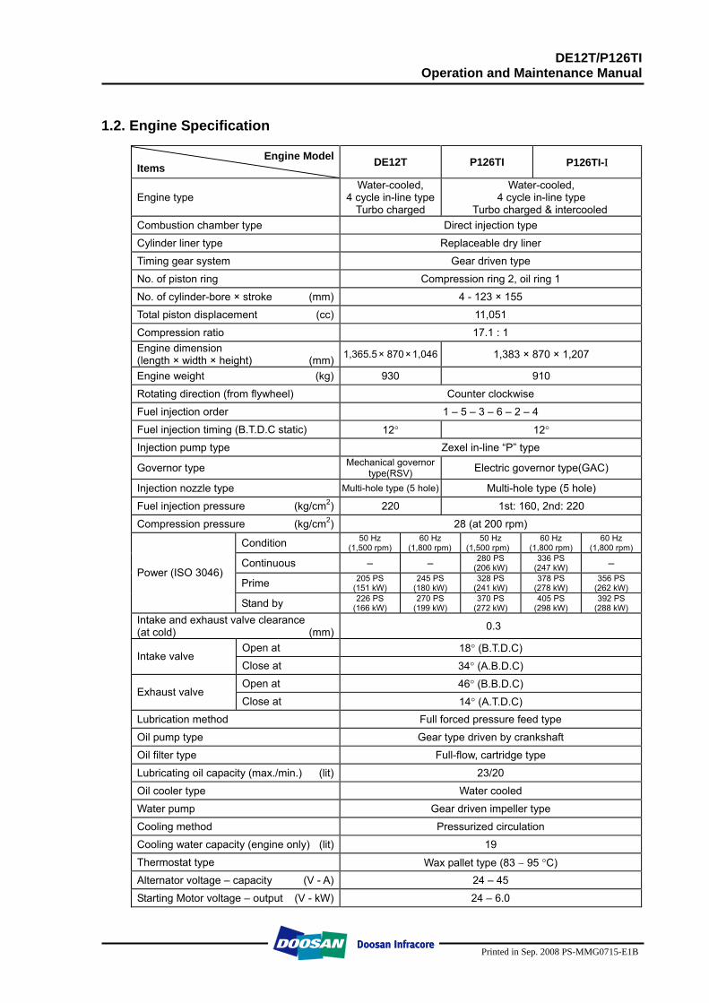
1.2. Engine Specification
Engine ModelItems DE12T P126TI P126TI-Ι
Engine type Water-cooled,
4 cycle in-line typeTurbo charged
Water-cooled, 4 cycle in-line type
Turbo charged & intercooled Combustion chamber type Direct injection type
Cylinder liner type Replaceable dry liner
Timing gear system Gear driven type
No. of piston ring Compression ring 2, oil ring 1
No. of cylinder-bore × stroke (mm) 4 - 123 × 155
Total piston displacement (cc) 11,051
Compression ratio 17.1 : 1 Engine dimension (length × width × height) (mm) 1,365.5 × 870 × 1,046 1,383 × 870 × 1,207
Engine weight (kg) 930 910
Rotating direction (from flywheel) Counter clockwise
Fuel injection order 1 – 5 – 3 – 6 – 2 – 4
Fuel injection timing (B.T.D.C static) 12° 12° Injection pump type Zexel in-line “P” type
Governor type Mechanical governor type(RSV) Electric governor type(GAC)
Injection nozzle type Multi-hole type (5 hole) Multi-hole type (5 hole)
Fuel injection pressure (kg/cm2) 220 1st: 160, 2nd: 220
Compression pressure (kg/cm2) 28 (at 200 rpm)
Condition 50 Hz (1,500 rpm)
60 Hz (1,800 rpm)
50 Hz (1,500 rpm)
60 Hz (1,800 rpm)
60 Hz (1,800 rpm)
Continuous – – 280 PS
(206 kW) 336 PS
(247 kW) –
Prime 205 PS (151 kW)
245 PS (180 kW)
328 PS (241 kW)
378 PS (278 kW)
356 PS (262 kW)
Power (ISO 3046)
Stand by 226 PS (166 kW)
270 PS (199 kW)
370 PS (272 kW)
405 PS (298 kW)
392 PS (288 kW)
Intake and exhaust valve clearance (at cold) (mm) 0.3
Open at 18° (B.T.D.C) Intake valve
Close at 34° (A.B.D.C) Open at 46° (B.B.D.C)
Exhaust valve Close at 14° (A.T.D.C)
Lubrication method Full forced pressure feed type
Oil pump type Gear type driven by crankshaft
Oil filter type Full-flow, cartridge type
Lubricating oil capacity (max./min.) (lit) 23/20
Oil cooler type Water cooled
Water pump Gear driven impeller type
Cooling method Pressurized circulation
Cooling water capacity (engine only) (lit) 19
Thermostat type Wax pallet type (83 ∼ 95 °C) Alternator voltage – capacity (V - A) 24 – 45
Starting Motor voltage – output (V - kW) 24 – 6.0
DE12T/P126TI Operation and Maintenance Manual
Printed in Sep. 2008 PS-MMG0715-E1B
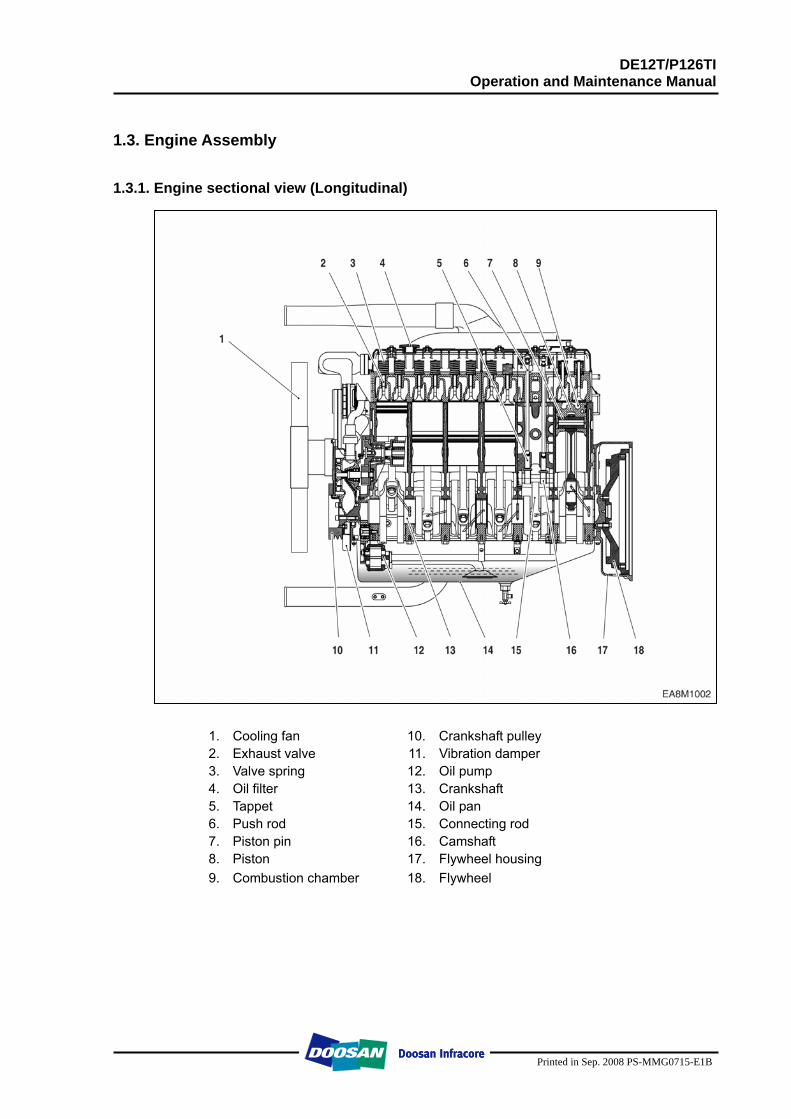
1.3. Engine Assembly 1.3.1. Engine sectional view (Longitudinal)
1. Cooling fan 10. Crankshaft pulley 2. Exhaust valve 11. Vibration damper 3. Valve spring 12. Oil pump 4. Oil filter 13. Crankshaft 5. Tappet 14. Oil pan 6. Push rod 15. Connecting rod 7. Piston pin 16. Camshaft 8. Piston 17. Flywheel housing 9. Combustion chamber 18. Flywheel
DE12T/P126TI Operation and Maintenance Manual
Printed in Sep. 2008 PS-MMG0715-E1B
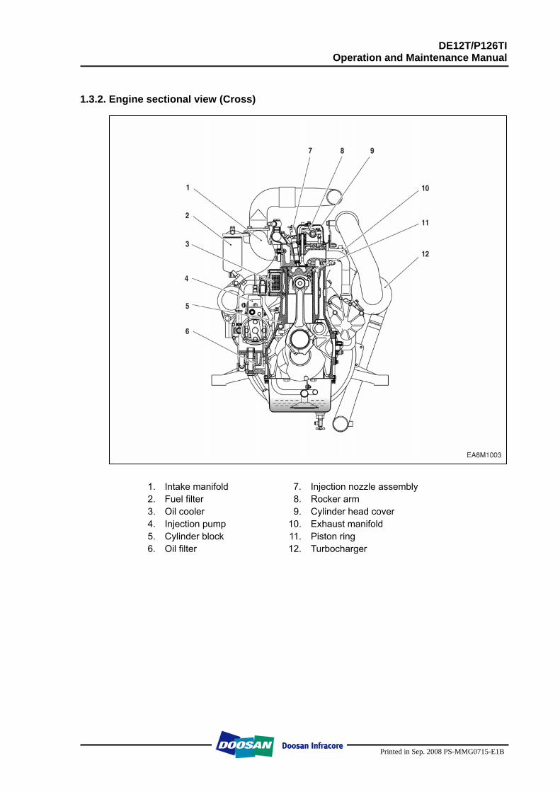
1.3.2. Engine sectional view (Cross)
1. Intake manifold 7. Injection nozzle assembly 2. Fuel filter 8. Rocker arm 3. Oil cooler 9. Cylinder head cover 4. Injection pump 10. Exhaust manifold 5. Cylinder block 11. Piston ring 6. Oil filter 12. Turbocharger
DE12T/P126TI Operation and Maintenance Manual
Printed in Sep. 2008 PS-MMG0715-E1B
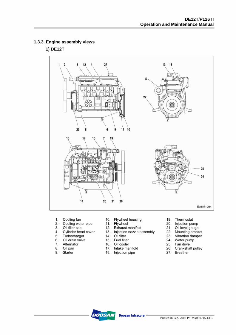
1.3.3. Engine assembly views
1) DE12T
1. Cooling fan 10. Flywheel housing 19. Thermostat 2. Cooling water pipe 11. Flywheel 20. Injection pump 3. Oil filler cap 12. Exhaust manifold 21. Oil level gauge 4. Cylinder head cover 13. Injection nozzle assembly 22. Mounting bracket 5. Turbocharger 14. Oil filter 23. Vibration damper 6. Oil drain valve 15. Fuel filter 24. Water pump 7. Alternator 16. Oil cooler 25. Fan drive 8. Oil pan 17. Intake manifold 26. Crankshaft pulley 9. Starter 18. Injection pipe 27. Breather
DE12T/P126TI Operation and Maintenance Manual
Printed in Sep. 2008 PS-MMG0715-E1B
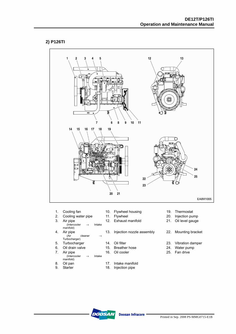
2) P126TI
1. Cooling fan 10. Flywheel housing 19. Thermostat 2. Cooling water pipe 11. Flywheel 20. Injection pump 3. Air pipe
(Intercooler → Intake manifold)
12. Exhaust manifold 21. Oil level gauge
4. Air pipe (Air cleaner →
Turbocharger)
13. Injection nozzle assembly 22. Mounting bracket
5. Turbocharger 14. Oil filter 23. Vibration damper 6. Oil drain valve 15. Breather hose 24. Water pump 7. Air pipe
(Intercooler → Intake manifold)
16. Oil cooler 25. Fan drive
8. Oil pan 17. Intake manifold 9. Starter 18. Injection pipe
DE12T/P126TI Operation and Maintenance Manual
Printed in Sep. 2008 PS-MMG0715-E1B
2. Technical Information
2.1. Engine Model and Serial Number
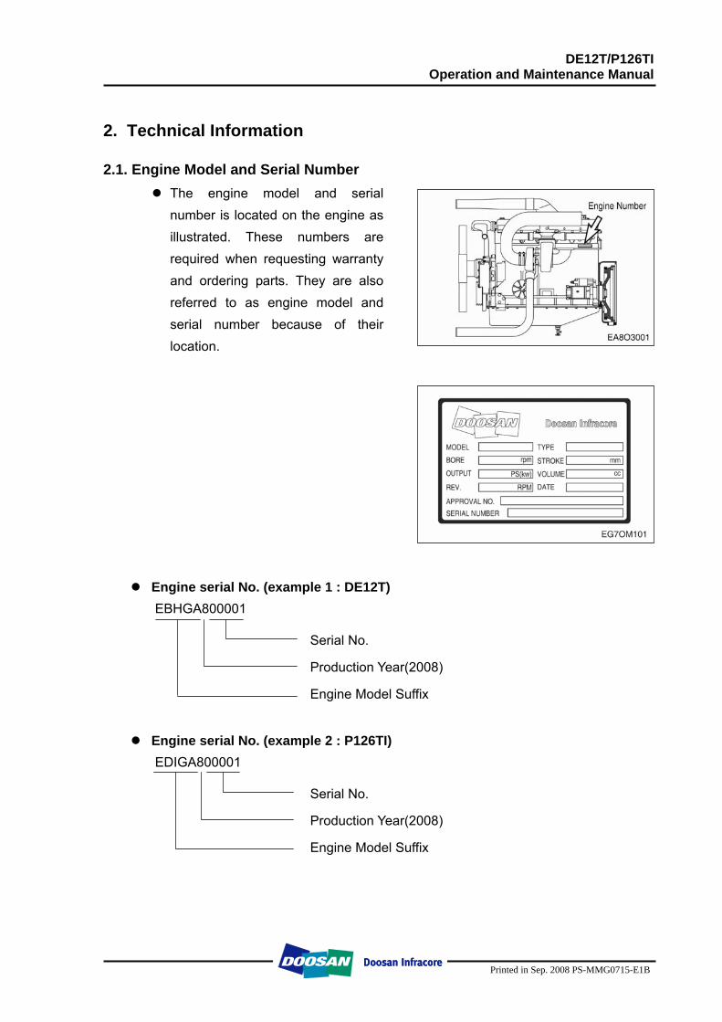
The engine model and serial number is located on the engine as illustrated. These numbers are required when requesting warranty and ordering parts. They are also referred to as engine model and serial number because of their location.
Engine serial No. (example 1 : DE12T) EBHGA800001
Serial No.
Production Year(2008)
Engine Model Suffix
Engine serial No. (example 2 : P126TI)
EDIGA800001
Serial No.
Production Year(2008)
Engine Model Suffix
DE12T/P126TI Operation and Maintenance Manual
Printed in Sep. 2008 PS-MMG0715-E1B
2.2. Engines Characteristic The Engines DE12T/ P126TI are in-line vertical water-cooled 6-cylinder four-
stroke diesel engines with direct injection. DE12T is turbo-charged engine, and P126TI model is turbo-charged and inter-cooled engine.
2.2.1. Oil gallery cooling type piston
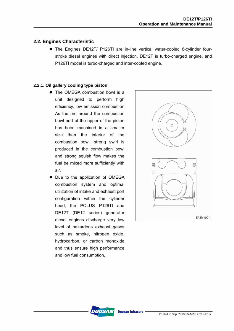
The OMEGA combustion bowl is a unit designed to perform high efficiency, low emission combustion. As the rim around the combustion bowl port of the upper of the piston has been machined in a smaller size than the interior of the combustion bowl, strong swirl is produced in the combustion bowl and strong squish flow makes the fuel be mixed more sufficiently with air.
Due to the application of OMEGA combustion system and optimal utilization of intake and exhaust port configuration within the cylinder head, the POLUS P126TI and DE12T (DE12 series) generator diesel engines discharge very low level of hazardous exhaust gases such as smoke, nitrogen oxide, hydrocarbon, or carbon monoxide and thus ensure high performance and low fuel consumption.
DE12T/P126TI Operation and Maintenance Manual
Printed in Sep. 2008 PS-MMG0715-E1B
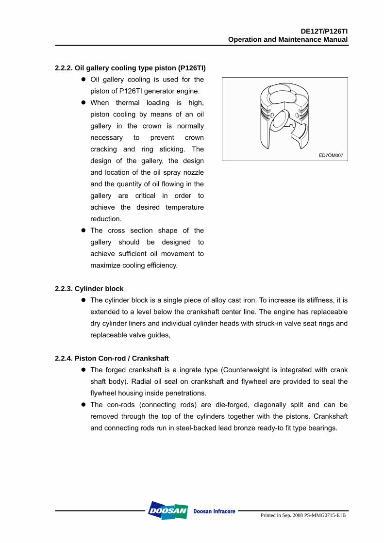
2.2.2. Oil gallery cooling type piston (P126TI)
Oil gallery cooling is used for the piston of P126TI generator engine.
When thermal loading is high, piston cooling by means of an oil gallery in the crown is normally necessary to prevent crown cracking and ring sticking. The design of the gallery, the design and location of the oil spray nozzle and the quantity of oil flowing in the gallery are critical in order to achieve the desired temperature reduction.
The cross section shape of the gallery should be designed to achieve sufficient oil movement to maximize cooling efficiency.
2.2.3. Cylinder block The cylinder block is a single piece of alloy cast iron. To increase its stiffness, it is
extended to a level below the crankshaft center line. The engine has replaceable dry cylinder liners and individual cylinder heads with struck-in valve seat rings and replaceable valve guides,
2.2.4. Piston Con-rod / Crankshaft The forged crankshaft is a ingrate type (Counterweight is integrated with crank
shaft body). Radial oil seal on crankshaft and flywheel are provided to seal the flywheel housing inside penetrations.
The con-rods (connecting rods) are die-forged, diagonally split and can be removed through the top of the cylinders together with the pistons. Crankshaft and connecting rods run in steel-backed lead bronze ready-to fit type bearings.
DE12T/P126TI Operation and Maintenance Manual
Printed in Sep. 2008 PS-MMG0715-E1B
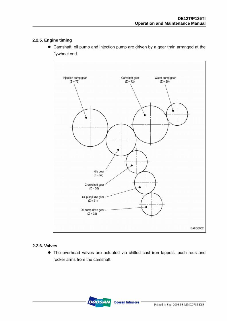
2.2.5. Engine timing
Camshaft, oil pump and injection pump are driven by a gear train arranged at the flywheel end.
2.2.6. Valves
The overhead valves are actuated via chilled cast iron tappets, push rods and rocker arms from the camshaft.
DE12T/P126TI Operation and Maintenance Manual
Printed in Sep. 2008 PS-MMG0715-E1B
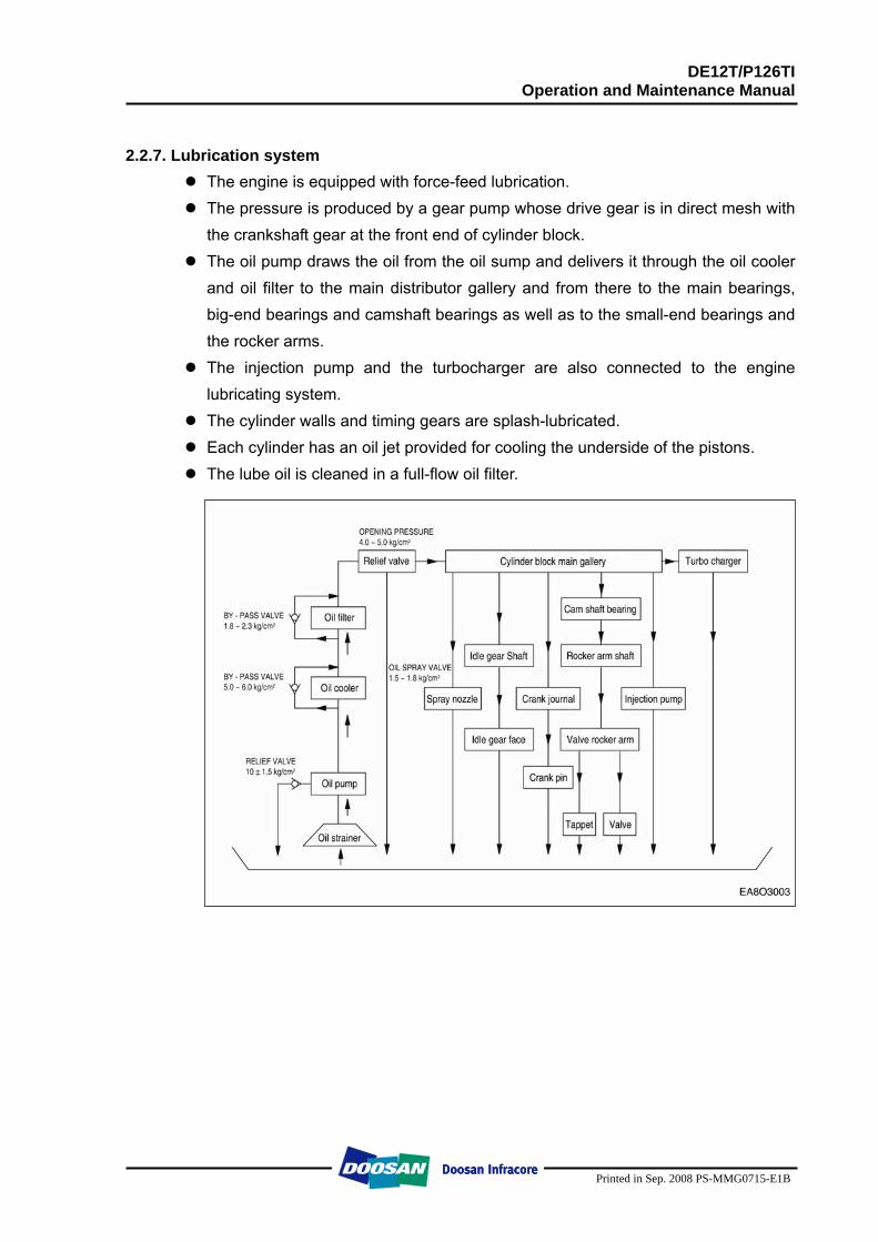
2.2.7. Lubrication system
The engine is equipped with force-feed lubrication. The pressure is produced by a gear pump whose drive gear is in direct mesh with
the crankshaft gear at the front end of cylinder block. The oil pump draws the oil from the oil sump and delivers it through the oil cooler
and oil filter to the main distributor gallery and from there to the main bearings, big-end bearings and camshaft bearings as well as to the small-end bearings and the rocker arms.
The injection pump and the turbocharger are also connected to the engine lubricating system.
The cylinder walls and timing gears are splash-lubricated. Each cylinder has an oil jet provided for cooling the underside of the pistons. The lube oil is cleaned in a full-flow oil filter.
DE12T/P126TI Operation and Maintenance Manual
Printed in Sep. 2008 PS-MMG0715-E1B
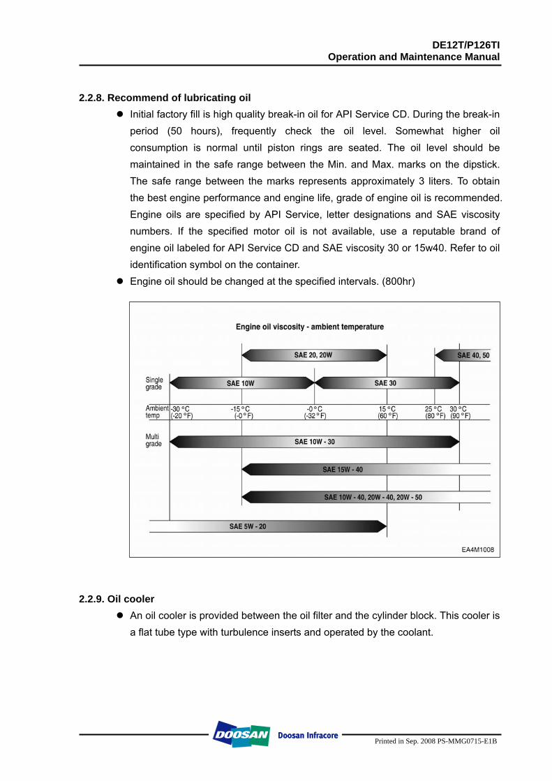
2.2.8. Recommend of lubricating oil
Initial factory fill is high quality break-in oil for API Service CD. During the break-in period (50 hours), frequently check the oil level. Somewhat higher oil consumption is normal until piston rings are seated. The oil level should be maintained in the safe range between the Min. and Max. marks on the dipstick. The safe range between the marks represents approximately 3 liters. To obtain the best engine performance and engine life, grade of engine oil is recommended. Engine oils are specified by API Service, letter designations and SAE viscosity numbers. If the specified motor oil is not available, use a reputable brand of engine oil labeled for API Service CD and SAE viscosity 30 or 15w40. Refer to oil identification symbol on the container.
Engine oil should be changed at the specified intervals. (800hr)
2.2.9. Oil cooler
An oil cooler is provided between the oil filter and the cylinder block. This cooler is a flat tube type with turbulence inserts and operated by the coolant.
DE12T/P126TI Operation and Maintenance Manual
Printed in Sep. 2008 PS-MMG0715-E1B
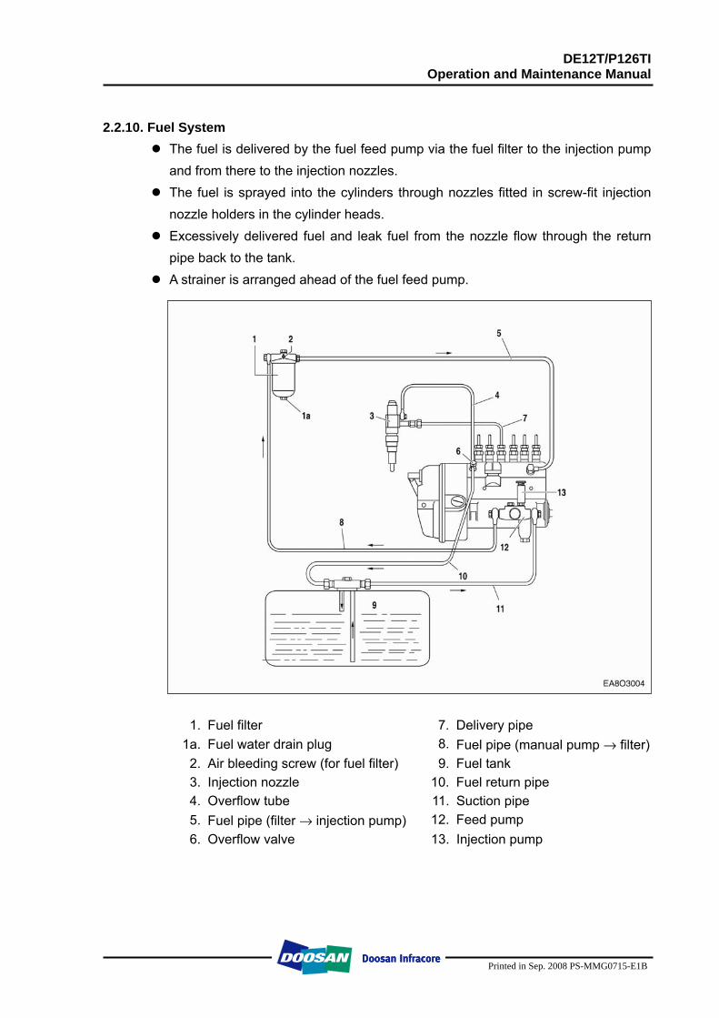
2.2.10. Fuel System
The fuel is delivered by the fuel feed pump via the fuel filter to the injection pump and from there to the injection nozzles.
The fuel is sprayed into the cylinders through nozzles fitted in screw-fit injection nozzle holders in the cylinder heads.
Excessively delivered fuel and leak fuel from the nozzle flow through the return pipe back to the tank.
A strainer is arranged ahead of the fuel feed pump.
1. Fuel filter 7. Delivery pipe 1a. Fuel water drain plug 8. Fuel pipe (manual pump → filter) 2. Air bleeding screw (for fuel filter) 9. Fuel tank 3. Injection nozzle 10. Fuel return pipe 4. Overflow tube 11. Suction pipe 5. Fuel pipe (filter → injection pump) 12. Feed pump 6. Overflow valve 13. Injection pump
DE12T/P126TI Operation and Maintenance Manual
Printed in Sep. 2008 PS-MMG0715-E1B
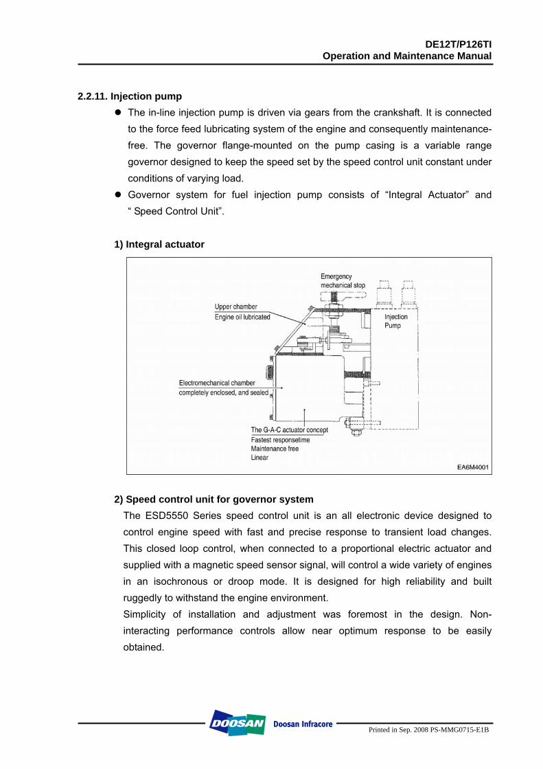
2.2.11. Injection pump
The in-line injection pump is driven via gears from the crankshaft. It is connected to the force feed lubricating system of the engine and consequently maintenance-free. The governor flange-mounted on the pump casing is a variable range governor designed to keep the speed set by the speed control unit constant under conditions of varying load.
Governor system for fuel injection pump consists of “Integral Actuator” and “ Speed Control Unit”.
1) Integral actuator
2) Speed control unit for governor system
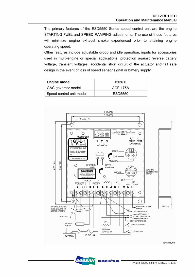
The ESD5550 Series speed control unit is an all electronic device designed to control engine speed with fast and precise response to transient load changes. This closed loop control, when connected to a proportional electric actuator and supplied with a magnetic speed sensor signal, will control a wide variety of engines in an isochronous or droop mode. It is designed for high reliability and built ruggedly to withstand the engine environment. Simplicity of installation and adjustment was foremost in the design. Non-interacting performance controls allow near optimum response to be easily obtained.
DE12T/P126TI Operation and Maintenance Manual
Printed in Sep. 2008 PS-MMG0715-E1B
The primary features of the ESD5550 Series speed control unit are the engine STARTING FUEL and SPEED RAMPING adjustments. The use of these features will minimize engine exhaust smoke experienced prior to attaining engine operating speed. Other features include adjustable droop and idle operation, inputs for accessories used in multi-engine or special applications, protection against reverse battery voltage, transient voltages, accidental short circuit of the actuator and fail safe design in the event of loss of speed sensor signal or battery supply.
Engine model P126TI GAC governor model ACE 175A Speed control unit model ESD5550
DE12T/P126TI Operation and Maintenance Manual
Printed in Sep. 2008 PS-MMG0715-E1B
2.2.11. Fuel requirements
DOOSAN marine diesel engines was designed to use Number 2-D diesel fuel or equivalent that meets specification DIN 51601-DK. For maximum fuel economy, Number 2-D fuel whenever possible. When temperatures are below -7 °C (20 °F), use Number 1-D fuel. If Number 1-D fuel is not available, the mixture of one kerosene to two gallons of Number 2-D fuel can be used. Once kerosene has been added, the engine should be run for several minutes to mix the fuel.
2.2.12. How to select fuel oil
Fuel quality is an important factor in obtaining satisfactory engine performance, long engine life, and acceptable exhaust emission levels. DOOSAN engines are designed to operate on most diesel fuels marketed today. In general, fuels meeting the properties of ASTM Designation D975 (grades 1-D and 2-D) have provided satisfactory performance.
The ASTM 975 specification, however, does not in itself adequately define the fuel characteristics needed for assurance of fuel quality.
The properties listed in the fuel oil selection chart below have provided optimum engine performance. Grade 2-D fuel is normally available for generator service. Grade 1-D fuel should not be used in pleasure craft engines, except in an emergency.
DE12T/P126TI Operation and Maintenance Manual
Printed in Sep. 2008 PS-MMG0715-E1B
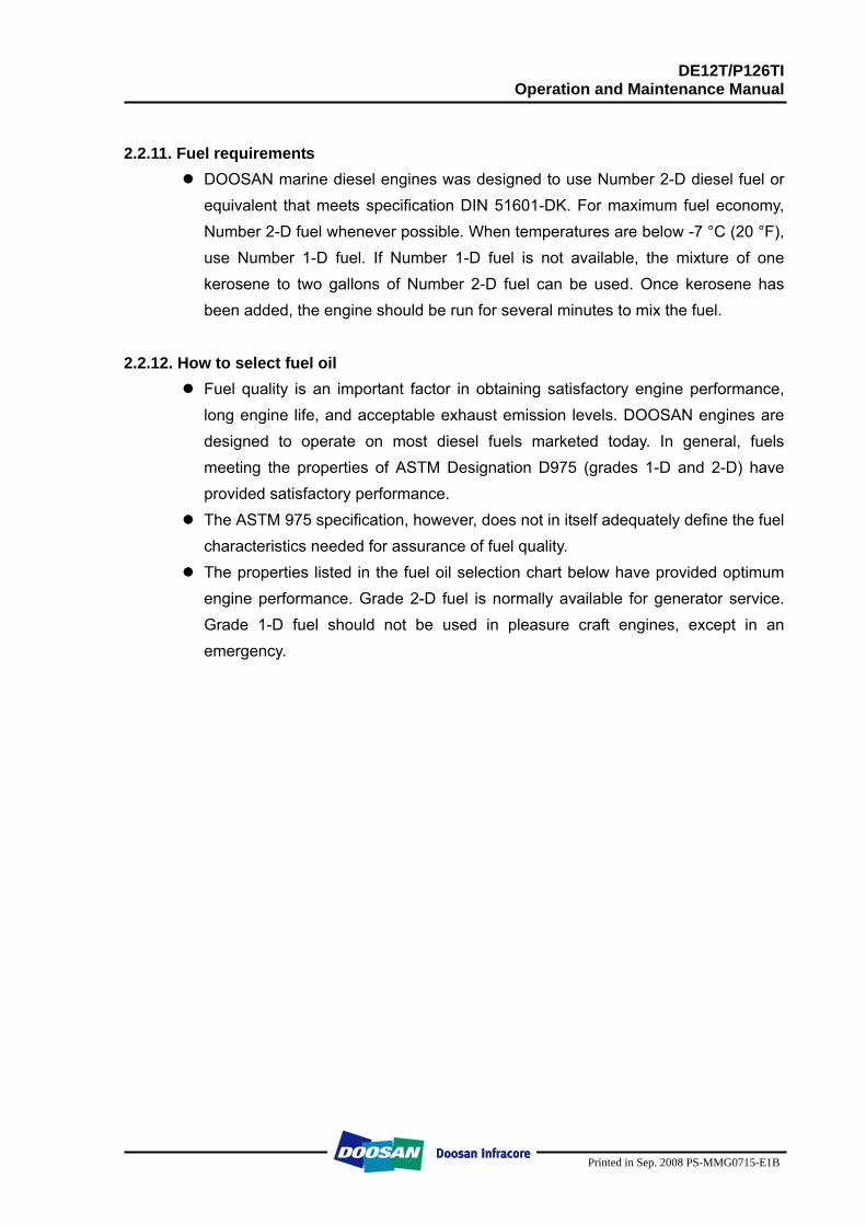
Fuel oil selection chart
General Fuel Classification
ASTM Test
No. 1 ASTM 1-D
No. 2 ASTM 2-D
DIN 51601
Gravity, °API #) D 287 40 ~ 44 33 ~ 37 0.815 ~ 0.855 Flash Point
Min. °F (°C) D 93 100 (38) 125 (52) 131 (55)
Viscosity, Kinematic CST 100 °F (40 °C )
D 445 1.3 ~ 2.4 1.9 ~ 4.1 1.8 ~ 10
Cloud Point °F #) D 2500 See Note 1) See Note 1) See Note 1) Sulfur Content
wt%, Max. D 129 0.5 0.5 0.15
Carbon Residue on 10%, wt%, Max.
D 524 0.15 0.35 0.1
Accelerated Stability Total Insolubles
mg/100 ml, Max. #) D 2274 1.5 1.5
Ash, wt%, Max. D 482 0.01 0.01 Cetane Number, Min. +) D 613 45 45 > 45
Distillation Temperature, °F (°C)
IMP, Typican #) 10% Typical #) 50% Typical #) 90% +) End Point #)
D 86
350(177) 385(196) 45(218)
500 (260) Max. 550(288) Max.
375(191) 430(221) 510(256)
625(329) Max. 675(357) Max.
680(360)
Water & Sediment %, Max.
D 1796 0.05 0.05 0.05
#) Not specified In ASTM D 975 +) Differs from ASTM D 975
NOTE: The cloud point should be 6 °C (10 °F) below the lowest expected fuel temperature to prevent clogging of fuel fitters by crystals.
DE12T/P126TI Operation and Maintenance Manual
Printed in Sep. 2008 PS-MMG0715-E1B
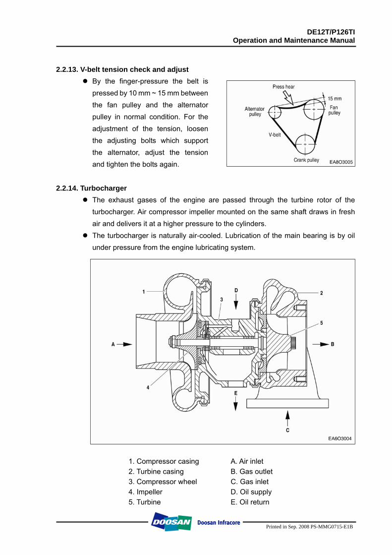
2.2.13. V-belt tension check and adjust
By the finger-pressure the belt is pressed by 10 mm ~ 15 mm between the fan pulley and the alternator pulley in normal condition. For the adjustment of the tension, loosen the adjusting bolts which support the alternator, adjust the tension and tighten the bolts again.
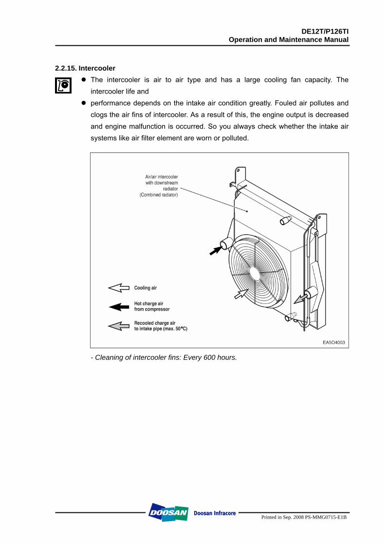
2.2.14. Turbocharger The exhaust gases of the engine are passed through the turbine rotor of the
turbocharger. Air compressor impeller mounted on the same shaft draws in fresh air and delivers it at a higher pressure to the cylinders.
The turbocharger is naturally air-cooled. Lubrication of the main bearing is by oil under pressure from the engine lubricating system.
1. Compressor casing A. Air inlet 2. Turbine casing B. Gas outlet 3. Compressor wheel C. Gas inlet 4. Impeller D. Oil supply 5. Turbine E. Oil return
DE12T/P126TI Operation and Maintenance Manual
Printed in Sep. 2008 PS-MMG0715-E1B
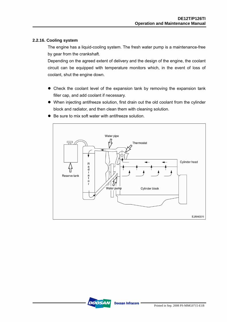
2.2.15. Intercooler
The intercooler is air to air type and has a large cooling fan capacity. The intercooler life and
performance depends on the intake air condition greatly. Fouled air pollutes and clogs the air fins of intercooler. As a result of this, the engine output is decreased and engine malfunction is occurred. So you always check whether the intake air systems like air filter element are worn or polluted.
- Cleaning of intercooler fins: Every 600 hours.
DE12T/P126TI Operation and Maintenance Manual
Printed in Sep. 2008 PS-MMG0715-E1B
2.2.16. Cooling system
The engine has a liquid-cooling system. The fresh water pump is a maintenance-free by gear from the crankshaft. Depending on the agreed extent of delivery and the design of the engine, the coolant circuit can be equipped with temperature monitors which, in the event of loss of coolant, shut the engine down.
Check the coolant level of the expansion tank by removing the expansion tank
filler cap, and add coolant if necessary. When injecting antifreeze solution, first drain out the old coolant from the cylinder
block and radiator, and then clean them with cleaning solution. Be sure to mix soft water with antifreeze solution.
DE12T/P126TI Operation and Maintenance Manual
Printed in Sep. 2008 PS-MMG0715-E1B
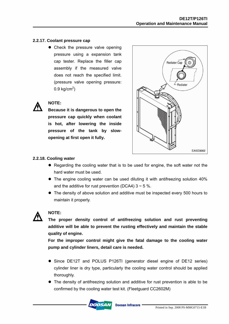
2.2.17. Coolant pressure cap
Check the pressure valve opening pressure using a expansion tank cap tester. Replace the filler cap assembly if the measured valve does not reach the specified limit. (pressure valve opening pressure: 0.9 kg/cm2)
NOTE: Because it is dangerous to open the pressure cap quickly when coolant is hot, after lowering the inside pressure of the tank by slow-opening at first open it fully.
2.2.18. Cooling water Regarding the cooling water that is to be used for engine, the soft water not the
hard water must be used. The engine cooling water can be used diluting it with antifreezing solution 40%
and the additive for rust prevention (DCA4) 3 ~ 5 %. The density of above solution and additive must be inspected every 500 hours to
maintain it properly.
NOTE: The proper density control of antifreezing solution and rust preventing additive will be able to prevent the rusting effectively and maintain the stable quality of engine. For the improper control might give the fatal damage to the cooling water pump and cylinder liners, detail care is needed.
Since DE12T and POLUS P126TI (generator diesel engine of DE12 series) cylinder liner is dry type, particularly the cooling water control should be applied thoroughly.
The density of antifreezing solution and additive for rust prevention is able to be confirmed by the cooling water test kit. (Fleetguard CC2602M)
DE12T/P126TI Operation and Maintenance Manual
Printed in Sep. 2008 PS-MMG0715-E1B
How to use the cooling water test kit
(1) When the cooling water temp. of engine is in the range of 10 ~ 55 °C, loosen the plug for cooling water discharge and fill the plastic cup about a half.
NOTE: In taking the cooling water sample, if the water in auxiliary tank were taken, it is hard to measure the accurate density. Take the cooling water sample necessarily loosening the cooling water discharge plug.
(2) At the state of a test paper soaked in the sampled water, after taking the
paper out through water agitation, shake off the water. (3) Wait for about 45 sec. till the color change of test paper.
NOTE: However, it should not elapse longer than 75 sec, and if it did, the hue would change.
(4) Make the numerical value by comparing the test paper which hue has changed with the color list of label on storage bottle.
(5) By comparing the hue changed into yellowish green or so with the green color indication of test paper storage bottle, confirm the density. (Then, the density indication must be in the hue range of 33% to 50%).
(6) The brown at the middle of test paper and the lower pink color indication represent the additive state for rust prevention, and the proper range is that the meeting numerical value of brown (vertical) and pink color (horizontal) locates in the range of 0.3 to 0.8 at the color list of label on the test paper storage bottle.
(7) In case of less than 0.3, replenish the additive for rust prevention (DCA4), and in case of more than 0.8, pour out the cooling water about 50% and then readjust the density after refilling with clean fresh water.
DE12T/P126TI Operation and Maintenance Manual
Printed in Sep. 2008 PS-MMG0715-E1B
Amount of anti-freeze in winter
Ambient temperature (°C) Cooling water (%) Anti-freeze (%)
Over -10 -10 -15 -20 -25 -30 -40
85 80 73 67 60 56 50
15 20 27 33 40 44 50
2.2.19. Fuel belt Use a fan belt of specified dimensions, and replace if damaged, frayed, or
deteriorated. � Check the fan belt for belt tension.
If belt tension is lower than the specified limit, adjust the tension by relocating the alternator. (specified deflection: 10 ~ 15 mm when pressed down with thumb)
2.2.20. Engine oil
Check oil level with the oil level gauge and replenish if necessary. Check the oil level with the engine cooled. If the engine is warm, allow time for 5 ~
10 minutes for oil drain into the crankcase before checking oil level. The oil level must be between Max and Min. lines on the gauge.
Engine oil should be changed at the specified intervals. (800 hr) Oil in the oil filter should be changed simultaneously. - First oil change : 50 hr operating
The oil viscosity grades should be selected SAE NO.15W40 and API CD or CE. 2.2.21. Oil filter
Check for oil pressure and oil leaks, and repair or replace the oil filter if necessary.
Change the oil filter cartridge simultaneously at every replacement of engine oil.
DE12T/P126TI Operation and Maintenance Manual
Printed in Sep. 2008 PS-MMG0715-E1B
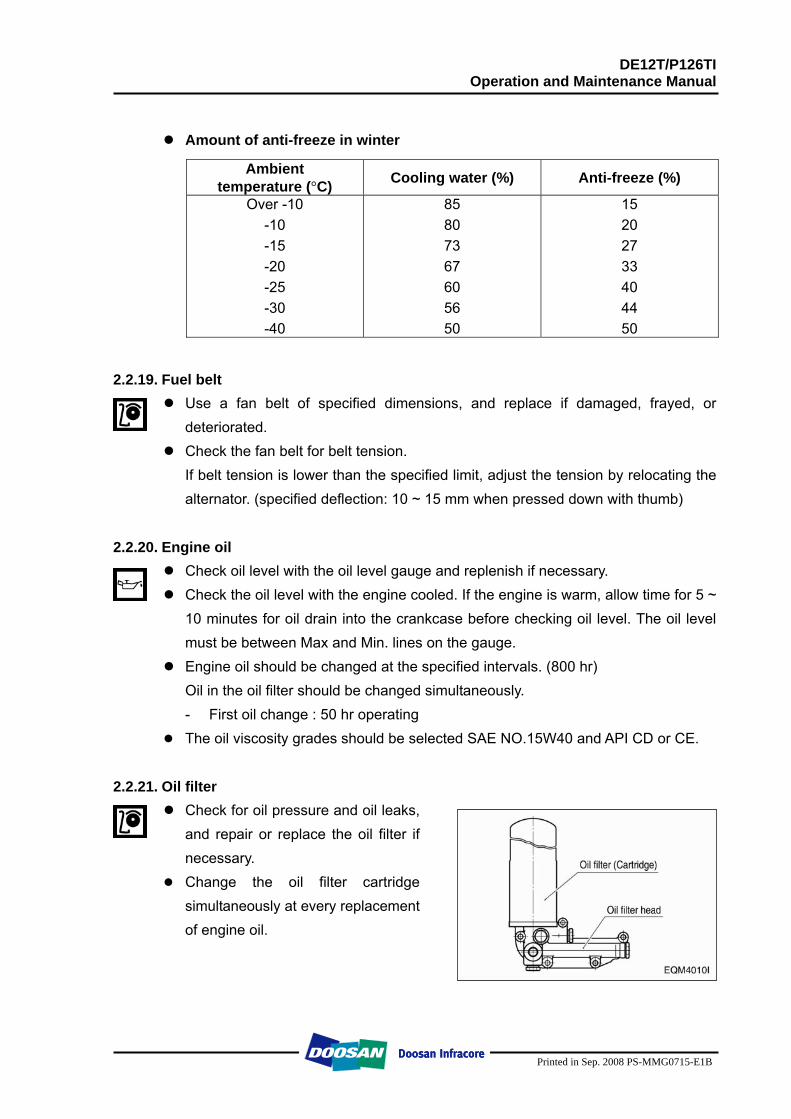
2.2.22. Fuel filter
Drain water in cartridge with loosening the cock under filter manually (6) from time to time.
The fuel filter should be replaced at every 1,200 hours.
2.2.23. Air cleaner
In case that elements are deformed, damaged or if the air cleaner has a crack, replace it.
By the definite interval, the elements must be cleaned and replaced.
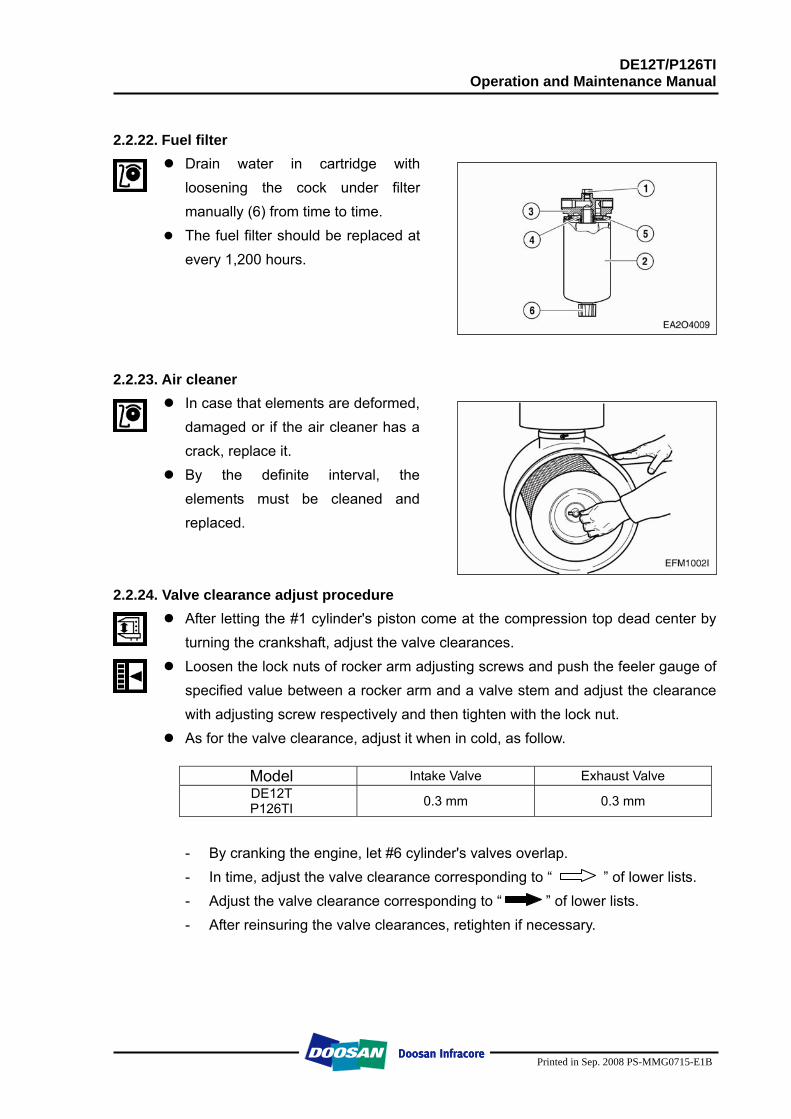
2.2.24. Valve clearance adjust procedure
After letting the #1 cylinder's piston come at the compression top dead center by turning the crankshaft, adjust the valve clearances.
Loosen the lock nuts of rocker arm adjusting screws and push the feeler gauge of specified value between a rocker arm and a valve stem and adjust the clearance with adjusting screw respectively and then tighten with the lock nut.
As for the valve clearance, adjust it when in cold, as follow.
Model Intake Valve Exhaust Valve DE12T P126TI 0.3 mm 0.3 mm
- By cranking the engine, let #6 cylinder's valves overlap. - In time, adjust the valve clearance corresponding to “ ” of lower lists. - Adjust the valve clearance corresponding to “ ” of lower lists. - After reinsuring the valve clearances, retighten if necessary.
DE12T/P126TI Operation and Maintenance Manual
Printed in Sep. 2008 PS-MMG0715-E1B
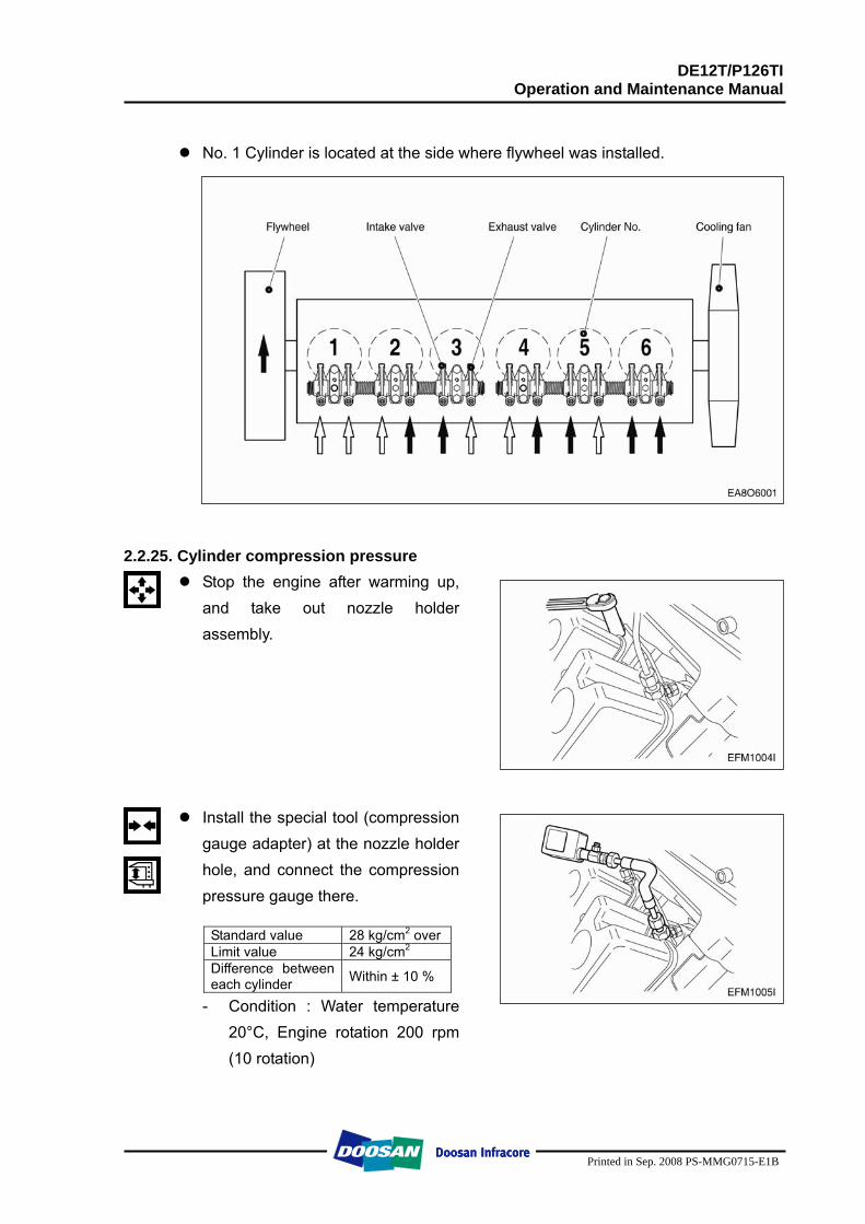
No. 1 Cylinder is located at the side where flywheel was installed.
2.2.25. Cylinder compression pressure Stop the engine after warming up,
and take out nozzle holder assembly.
Install the special tool (compression gauge adapter) at the nozzle holder hole, and connect the compression pressure gauge there.
Standard value 28 kg/cm2 over Limit value 24 kg/cm2 Difference between each cylinder Within ± 10 %
- Condition : Water temperature 20°C, Engine rotation 200 rpm (10 rotation)
DE12T/P126TI Operation and Maintenance Manual
Printed in Sep. 2008 PS-MMG0715-E1B
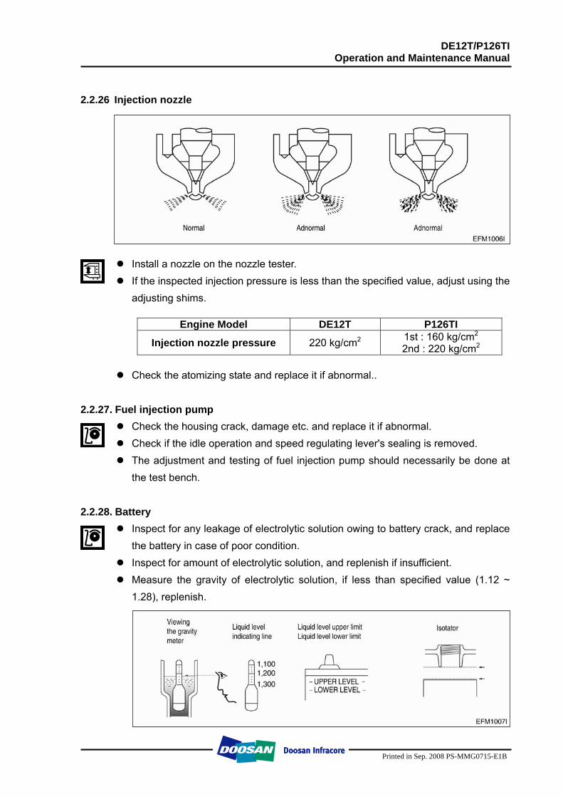
2.2.26 Injection nozzle
Install a nozzle on the nozzle tester. If the inspected injection pressure is less than the specified value, adjust using the
adjusting shims.
Engine Model DE12T P126TI
Injection nozzle pressure 220 kg/cm2 1st : 160 kg/cm2
2nd : 220 kg/cm2
Check the atomizing state and replace it if abnormal.. 2.2.27. Fuel injection pump
Check the housing crack, damage etc. and replace it if abnormal. Check if the idle operation and speed regulating lever's sealing is removed. The adjustment and testing of fuel injection pump should necessarily be done at
the test bench.
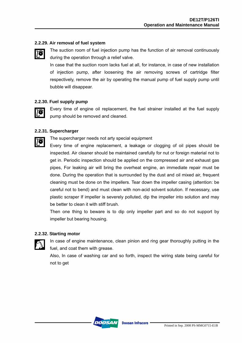
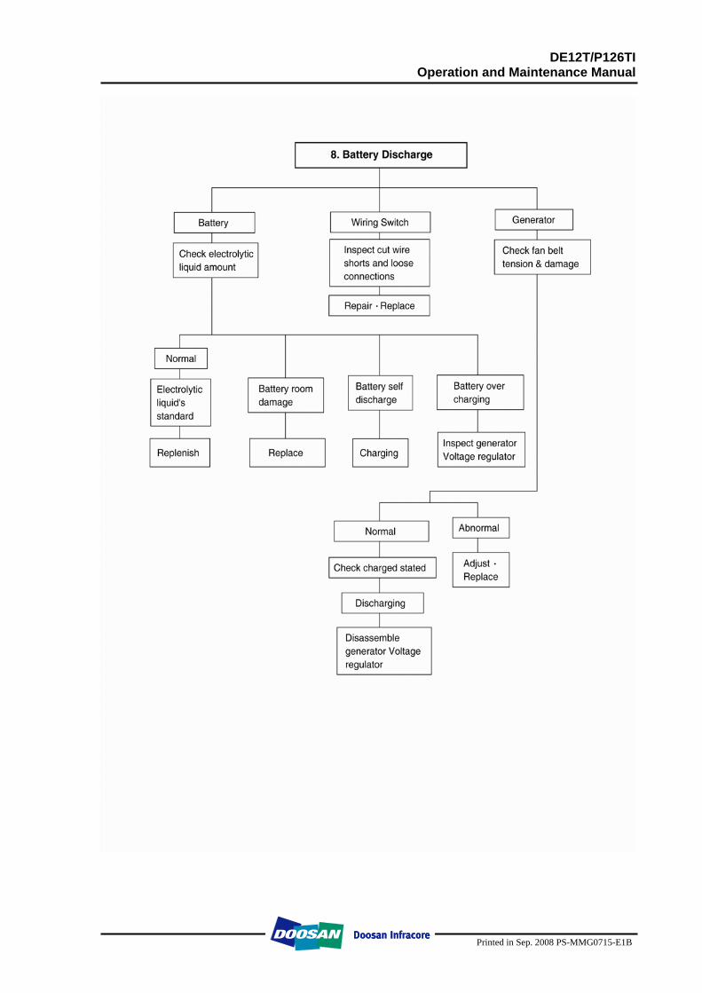
2.2.28. Battery Inspect for any leakage of electrolytic solution owing to battery crack, and replace
the battery in case of poor condition. Inspect for amount of electrolytic solution, and replenish if insufficient. Measure the gravity of electrolytic solution, if less than specified value (1.12 ~
1.28), replenish.
DE12T/P126TI Operation and Maintenance Manual
Printed in Sep. 2008 PS-MMG0715-E1B
2.2.29. Air removal of fuel system
The suction room of fuel injection pump has the function of air removal continuously during the operation through a relief valve. In case that the suction room lacks fuel at all, for instance, in case of new installation of injection pump, after loosening the air removing screws of cartridge filter respectively, remove the air by operating the manual pump of fuel supply pump until bubble will disappear.
2.2.30. Fuel supply pump
Every time of engine oil replacement, the fuel strainer installed at the fuel supply pump should be removed and cleaned.
2.2.31. Supercharger
The supercharger needs not arty special equipment Every time of engine replacement, a leakage or clogging of oil pipes should be inspected. Air cleaner should be maintained carefully for nut or foreign material not to get in. Periodic inspection should be applied on the compressed air and exhaust gas pipes, For leaking air will bring the overheat engine, an immediate repair must be done. During the operation that is surrounded by the dust and oil mixed air, frequent cleaning must be done on the impellers. Tear down the impeller casing (attention: be careful not to bend) and must clean with non-acid solvent solution. If necessary, use plastic scraper If impeller is severely polluted, dip the impeller into solution and may be better to clean it with stiff brush. Then one thing to beware is to dip only impeller part and so do not support by impeller but bearing housing.
2.2.32. Starting motor
In case of engine maintenance, clean pinion and ring gear thoroughly putting in the fuel, and coat them with grease. Also, In case of washing car and so forth, inspect the wiring state being careful for not to get
DE12T/P126TI Operation and Maintenance Manual
Printed in Sep. 2008 PS-MMG0715-E1B
2.2.33. Electrical equipment
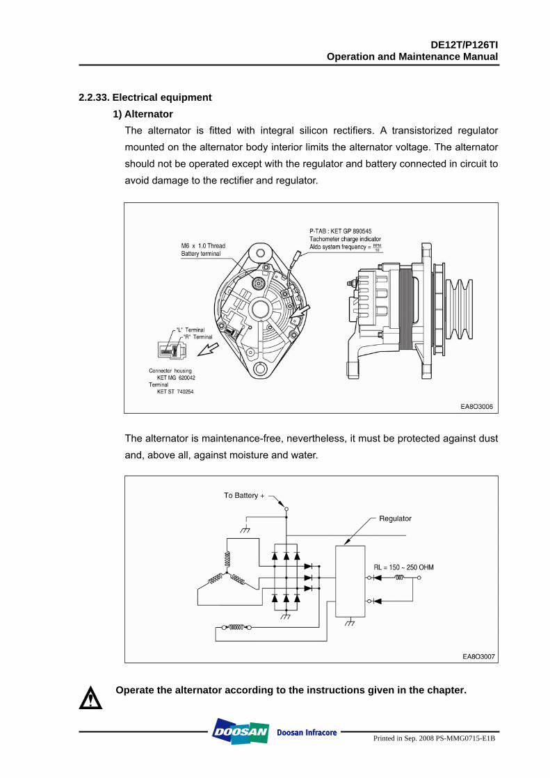
1) Alternator The alternator is fitted with integral silicon rectifiers. A transistorized regulator mounted on the alternator body interior limits the alternator voltage. The alternator should not be operated except with the regulator and battery connected in circuit to avoid damage to the rectifier and regulator.
The alternator is maintenance-free, nevertheless, it must be protected against dust and, above all, against moisture and water.
Operate the alternator according to the instructions given in the chapter.
DE12T/P126TI Operation and Maintenance Manual
Printed in Sep. 2008 PS-MMG0715-E1B
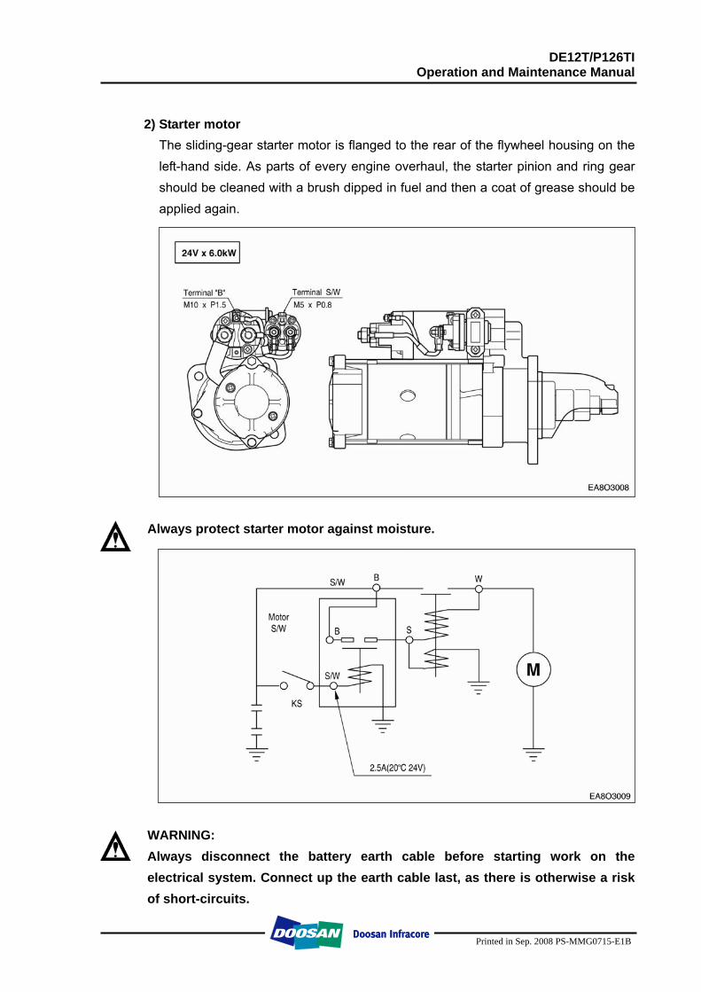
2) Starter motor
The sliding-gear starter motor is flanged to the rear of the flywheel housing on the left-hand side. As parts of every engine overhaul, the starter pinion and ring gear should be cleaned with a brush dipped in fuel and then a coat of grease should be applied again.
Always protect starter motor against moisture.
WARNING: Always disconnect the battery earth cable before starting work on the electrical system. Connect up the earth cable last, as there is otherwise a risk of short-circuits.
DE12T/P126TI Operation and Maintenance Manual
Printed in Sep. 2008 PS-MMG0715-E1B
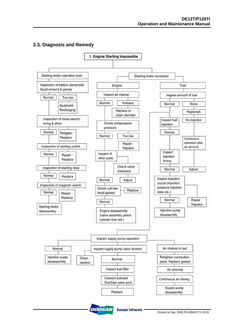
2.3. Diagnosis and Remedy
DE12T/P126TI Operation and Maintenance Manual
Printed in Sep. 2008 PS-MMG0715-E1B
DE12T/P126TI Operation and Maintenance Manual
Printed in Sep. 2008 PS-MMG0715-E1B
DE12T/P126TI Operation and Maintenance Manual
Printed in Sep. 2008 PS-MMG0715-E1B
DE12T/P126TI Operation and Maintenance Manual
Printed in Sep. 2008 PS-MMG0715-E1B
DE12T/P126TI Operation and Maintenance Manual
Printed in Sep. 2008 PS-MMG0715-E1B
DE12T/P126TI Operation and Maintenance Manual
Printed in Sep. 2008 PS-MMG0715-E1B
DE12T/P126TI Operation and Maintenance Manual
Printed in Sep. 2008 PS-MMG0715-E1B
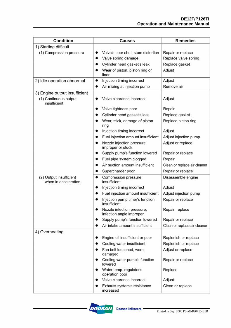
Condition Causes Remedies
1) Starting difficult (1) Compression pressure Valve's poor shut, stem distortion Repair or replace
Valve spring damage Replace valve spring Cylinder head gasket's leak Replace gasket Wear of piston, piston ring or
liner Adjust
2) Idle operation abnormal Injection timing incorrect Adjust Air mixing at injection pump Remove air
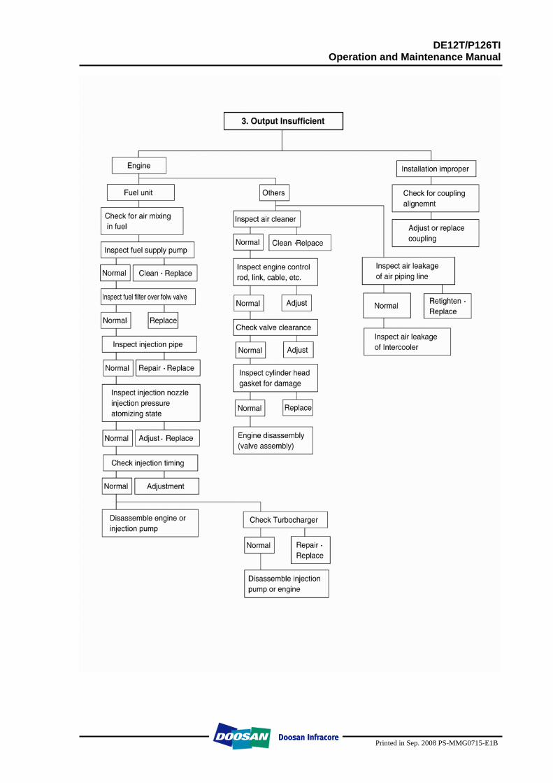
3) Engine output insufficient (1) Continuous output
insufficient Valve clearance incorrect Adjust
Valve tightness poor Repair Cylinder head gasket's leak Replace gasket Wear, stick, damage of piston
ring Replace piston ring
Injection timing incorrect Adjust Fuel injection amount insufficient Adjust injection pump Nozzle injection pressure
improper or stuck Adjust or replace
Supply pump's function lowered Repair or replace Fuel pipe system clogged Repair Air suction amount insufficient Clean or replace air cleaner Supercharger poor Repair or replace
(2) Output insufficient when in acceleration
Compression pressure insufficient
Disassemble engine
Injection timing incorrect Adjust Fuel injection amount insufficient Adjust injection pump Injection pump timer's function
insufficient Repair or replace
Nozzle infection pressure, infection angle improper
Repair, replace
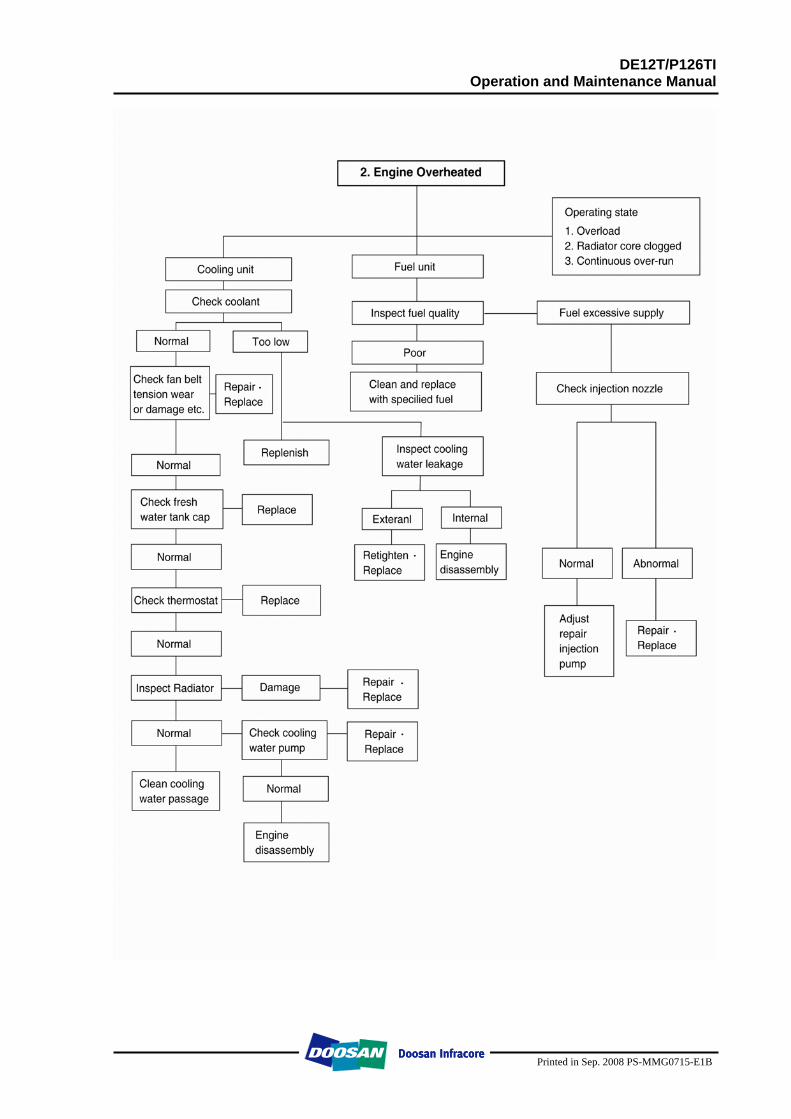
Supply pump's function lowered Repair or replace Air intake amount insufficient Clean or replace air cleaner 4) Overheating Engine oil insufficient or poor Replenish or replace Cooling water insufficient Replenish or replace Fan belt loosened, worn,
damaged Adjust or replace
Cooling water pump's function lowered
Repair or replace
Water temp. regulator's operation poor
Replace
Valve clearance incorrect Adjust Exhaust system's resistance
increased Clean or replace
DE12T/P126TI Operation and Maintenance Manual
Printed in Sep. 2008 PS-MMG0715-E1B
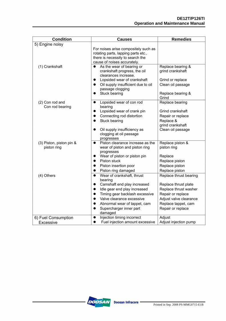
Condition Causes Remedies
5) Engine noisy For noises arise compositely such as
rotating parts, lapping parts etc., there is necessity to search the cause of noises accurately.
(1) Crankshaft
As the wear of bearing or crankshaft progress, the oil clearances increase.
Replace bearing & grind crankshaft
Lopsided wear of crankshaft Grind or replace Oil supply insufficient due to oil
passage clogging Clean oil passage
Stuck bearing Replace bearing & Grind
(2) Con rod and Con rod bearing
Lopsided wear of con rod bearing
Replace bearing
Lopsided wear of crank pin Grind crankshaft Connecting rod distortion Repair or replace Stuck bearing Replace &
grind crankshaft Oil supply insufficiency as
clogging at oil passage progresses
Clean oil passage
(3) Piston, piston pin & piston ring
Piston clearance increase as the wear of piston and piston ring progresses
Replace piston & piston ring
Wear of piston or piston pin Replace Piston stuck Replace piston Piston insertion poor Replace piston Piston ring damaged Replace piston
(4) Others
Wear of crankshaft, thrust bearing
Replace thrust bearing
Camshaft end play increased Replace thrust plate Idle gear end play increased Replace thrust washer Timing gear backlash excessive Repair or replace Valve clearance excessive Adjust valve clearance Abnormal wear of tappet, cam Replace tappet, cam Supercharger inner part
damaged Repair or replace
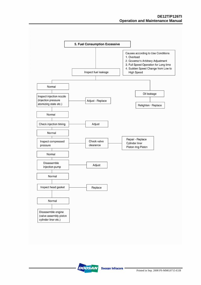
Injection timing incorrect Adjust 6) Fuel Consumption Excessive Fuel injection amount excessive Adjust injection pump
DE12T/P126TI Operation and Maintenance Manual
Printed in Sep. 2008 PS-MMG0715-E1B
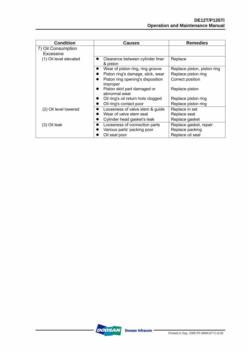
Condition Causes Remedies
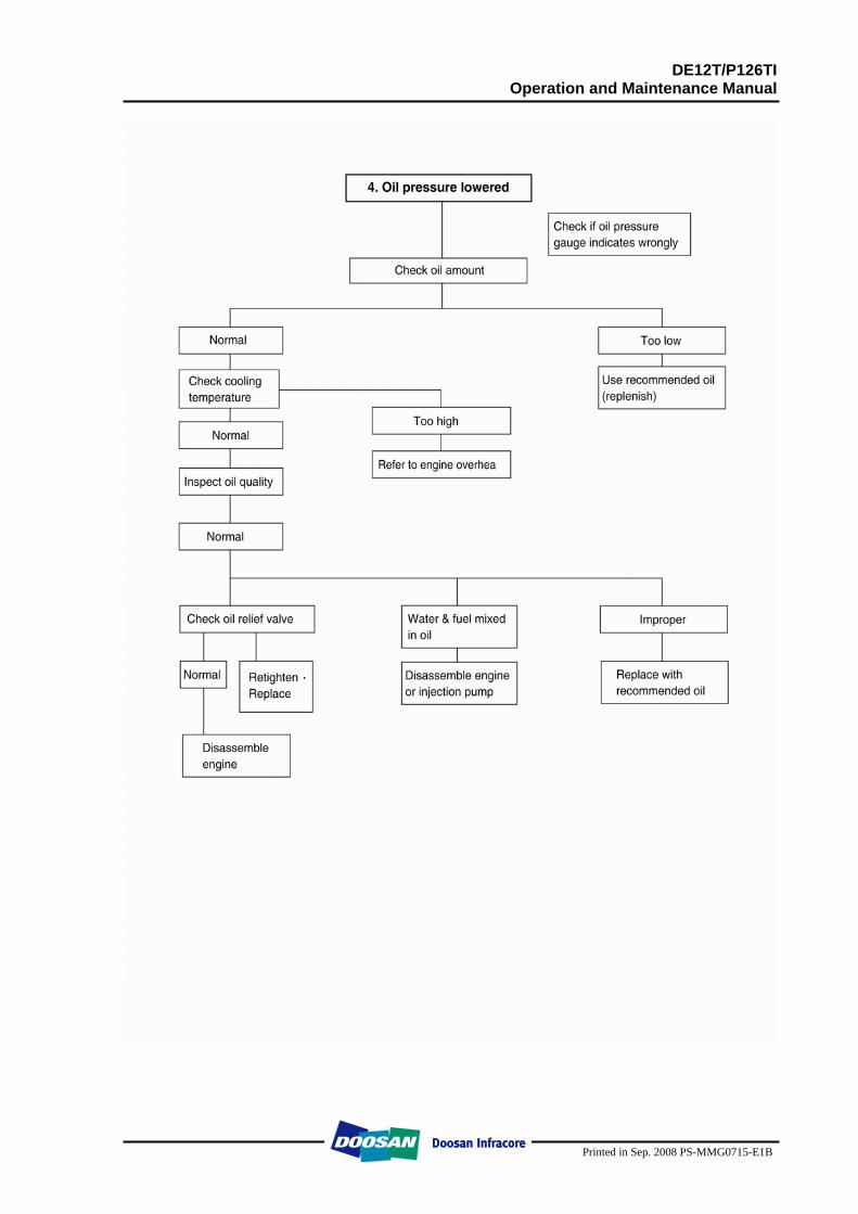
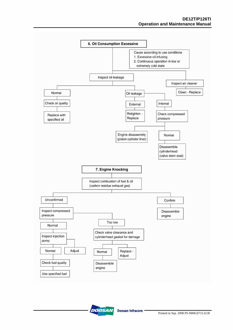
7) Oil Consumption Excessive
(1) Oil level elevated Clearance between cylinder liner & piston
Replace
Wear of piston ring, ring groove Replace piston, piston ring Piston ring's damage, stick, wear Replace piston ring Piston ring opening's disposition
improper Correct position
Piston skirt part damaged or abnormal wear
Replace piston
Oil ring's oil return hole clogged Replace piston ring Oil ring's contact poor Replace piston ring
(2) Oil level lowered Looseness of valve stem & guide Replace in set Wear of valve stem seal Replace seal Cylinder head gasket’s leak Replace gasket
(3) Oil leak Looseness of connection parts Replace gasket, repair Various parts' packing poor Replace packing Oil seal poor Replace oil seal
DE12T/P126TI Operation and Maintenance Manual
Printed in Sep. 2008 PS-MMG0715-E1B
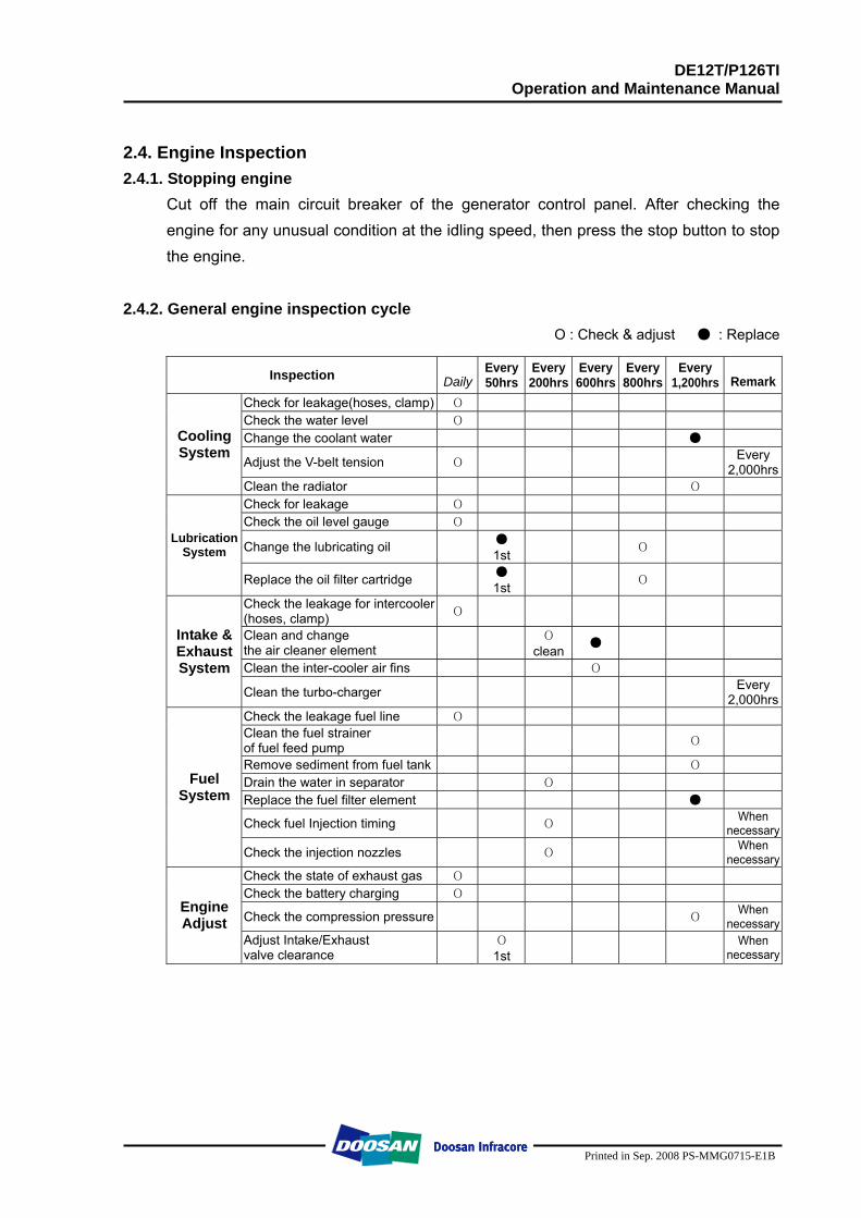
2.4. Engine Inspection 2.4.1. Stopping engine
Cut off the main circuit breaker of the generator control panel. After checking the engine for any unusual condition at the idling speed, then press the stop button to stop the engine.
2.4.2. General engine inspection cycle Ο : Check & adjust ● : Replace
Inspection DailyEvery50hrs
Every200hrs
Every 600hrs
Every 800hrs
Every 1,200hrs Remark
Check for leakage(hoses, clamp) О Check the water level О Change the coolant water ●
Adjust the V-belt tension О Every 2,000hrs
Cooling System
Clean the radiator О Check for leakage О Check the oil level gauge О
Change the lubricating oil ● 1st О
Lubrication System
Replace the oil filter cartridge ● 1st О
Check the leakage for intercooler(hoses, clamp) О
Clean and change the air cleaner element О
clean ●
Clean the inter-cooler air fins О
Intake & Exhaust System
Clean the turbo-charger Every 2,000hrs
Check the leakage fuel line О Clean the fuel strainer of fuel feed pump О
Remove sediment from fuel tank О Drain the water in separator О Replace the fuel filter element ●
Check fuel Injection timing О When necessary
Fuel System
Check the injection nozzles О When necessary
Check the state of exhaust gas О Check the battery charging О
Check the compression pressure О When necessary
Engine Adjust
Adjust Intake/Exhaust valve clearance О
1st When necessary
DE12T/P126TI Operation and Maintenance Manual
Printed in Sep. 2008 PS-MMG0715-E1B
2.4.3. Use of original parts for repair and replacement
For engine is being mechanically harmonized with many parts, only when the original parts that the manufacture recommends to use is used, the engine trouble would be preventively maintained and capable to keep up the maximum performances. For the analogous parts not the original parts are poor in qualities and gives ill performances, it may rather bring early engine failure.
DE12T/P126TI Operation and Maintenance Manual
Printed in Sep. 2008 PS-MMG0715-E1B
3. Disassembly and Reassembly of Major Components 3.1. Disassembly
3.1.1. General precautions Maintenance operation should be carried out in a bright and clean place. Before disassembly, provide parts racks for storage of various tools and
disassembled parts. Arrange the disassembled parts in the disassembly sequence and use care to
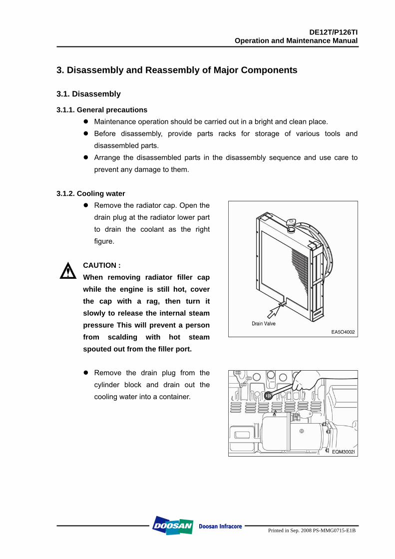
prevent any damage to them. 3.1.2. Cooling water
Remove the radiator cap. Open the drain plug at the radiator lower part to drain the coolant as the right figure.
CAUTION : When removing radiator filler cap while the engine is still hot, cover the cap with a rag, then turn it slowly to release the internal steam pressure This will prevent a person from scalding with hot steam spouted out from the filler port.
Remove the drain plug from the
cylinder block and drain out the cooling water into a container.
DE12T/P126TI Operation and Maintenance Manual
Printed in Sep. 2008 PS-MMG0715-E1B
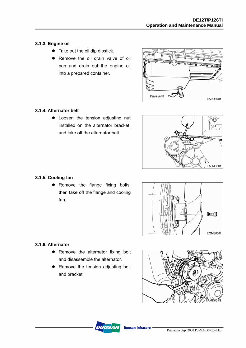
3.1.3. Engine oil
Take out the oil dip dipstick. Remove the oil drain valve of oil
pan and drain out the engine oil into a prepared container.
3.1.4. Alternator belt
Loosen the tension adjusting nut installed on the alternator bracket, and take off the alternator belt.
3.1.5. Cooling fan
Remove the flange fixing bolts, then take off the flange and cooling fan.
3.1.6. Alternator Remove the alternator fixing bolt
and disassemble the alternator. Remove the tension adjusting bolt
and bracket.
DE12T/P126TI Operation and Maintenance Manual
Printed in Sep. 2008 PS-MMG0715-E1B
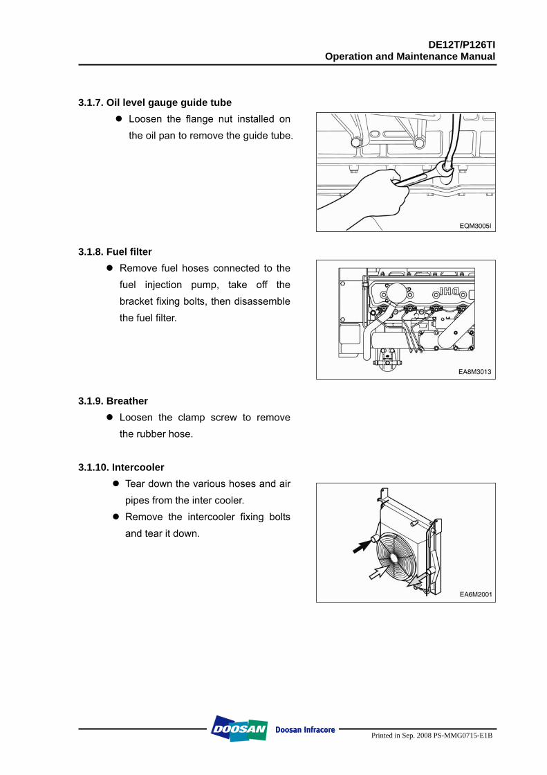
3.1.7. Oil level gauge guide tube Loosen the flange nut installed on
the oil pan to remove the guide tube.
3.1.8. Fuel filter Remove fuel hoses connected to the
fuel injection pump, take off the bracket fixing bolts, then disassemble the fuel filter.
3.1.9. Breather
Loosen the clamp screw to remove the rubber hose.
3.1.10. Intercooler
Tear down the various hoses and air pipes from the inter cooler.
Remove the intercooler fixing bolts and tear it down.
DE12T/P126TI Operation and Maintenance Manual
Printed in Sep. 2008 PS-MMG0715-E1B
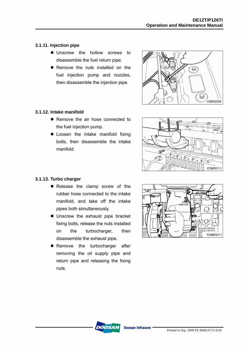
3.1.11. Injection pipe Unscrew the hollow screws to disassemble the fuel return pipe.
Remove the nuts installed on the fuel injection pump and nozzles, then disassemble the injection pipe.
3.1.12. Intake manifold Remove the air hose connected to the fuel injection pump.
Loosen the intake manifold fixing bolts, then disassemble the intake manifold.
3.1.13. Turbo charger
Release the clamp screw of the rubber hose connected to the intake manifold, and take off the intake pipes both simultaneously.
Unscrew the exhaust pipe bracket fixing bolts, release the nuts installed on the turbocharger, then disassemble the exhaust pipe.
Remove the turbocharger after removing the oil supply pipe and return pipe and releasing the fixing nuts.
DE12T/P126TI Operation and Maintenance Manual
Printed in Sep. 2008 PS-MMG0715-E1B
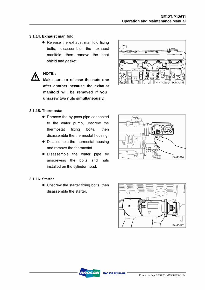
3.1.14. Exhaust manifold
Release the exhaust manifold fixing bolts, disassemble the exhaust manifold, then remove the heat shield and gasket.
NOTE : Make sure to release the nuts one after another because the exhaust manifold will be removed if you unscrew two nuts simultaneously.
3.1.15. Thermostat
Remove the by-pass pipe connected to the water pump, unscrew the thermostat fixing bolts, then disassemble the thermostat housing.
Disassemble the thermostat housing and remove the thermostat.
Disassemble the water pipe by unscrewing the bolts and nuts installed on the cylinder head.
3.1.16. Starter
Unscrew the starter fixing bolts, then disassemble the starter.
DE12T/P126TI Operation and Maintenance Manual
Printed in Sep. 2008 PS-MMG0715-E1B
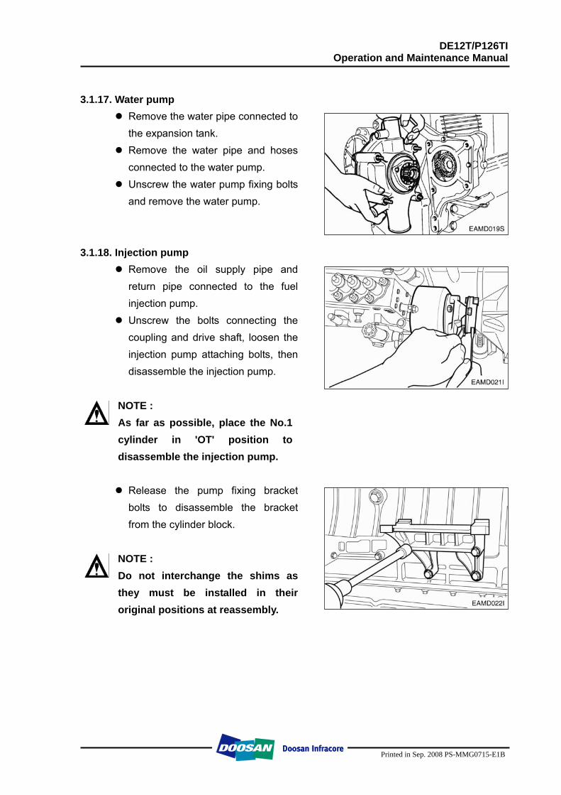
3.1.17. Water pump
Remove the water pipe connected to the expansion tank.
Remove the water pipe and hoses connected to the water pump.
Unscrew the water pump fixing bolts and remove the water pump.
3.1.18. Injection pump
Remove the oil supply pipe and return pipe connected to the fuel injection pump.
Unscrew the bolts connecting the coupling and drive shaft, loosen the injection pump attaching bolts, then disassemble the injection pump.
NOTE : As far as possible, place the No.1 cylinder in 'OT' position to disassemble the injection pump.
Release the pump fixing bracket bolts to disassemble the bracket from the cylinder block.
NOTE : Do not interchange the shims as they must be installed in their original positions at reassembly.
DE12T/P126TI Operation and Maintenance Manual
Printed in Sep. 2008 PS-MMG0715-E1B
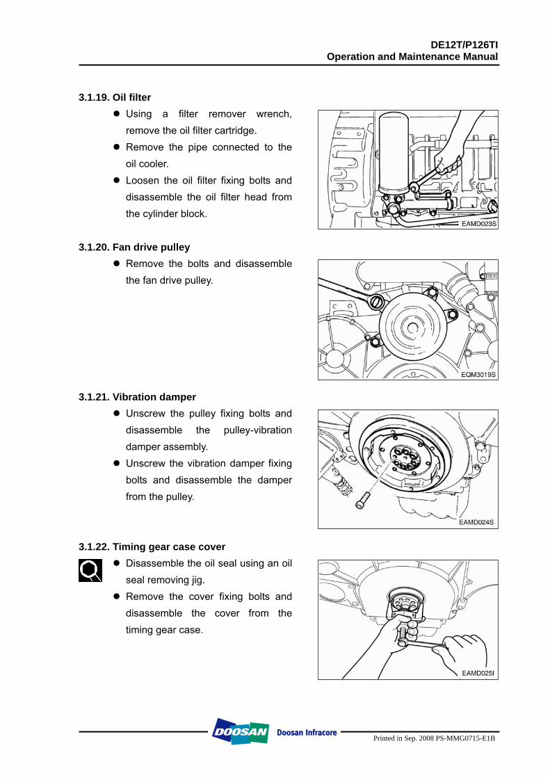
3.1.19. Oil filter
Using a filter remover wrench, remove the oil filter cartridge.
Remove the pipe connected to the oil cooler.
Loosen the oil filter fixing bolts and disassemble the oil filter head from the cylinder block.
3.1.20. Fan drive pulley
Remove the bolts and disassemble the fan drive pulley.
3.1.21. Vibration damper
Unscrew the pulley fixing bolts and disassemble the pulley-vibration damper assembly.
Unscrew the vibration damper fixing bolts and disassemble the damper from the pulley.
3.1.22. Timing gear case cover
Disassemble the oil seal using an oil seal removing jig.
Remove the cover fixing bolts and disassemble the cover from the timing gear case.
DE12T/P126TI Operation and Maintenance Manual
Printed in Sep. 2008 PS-MMG0715-E1B
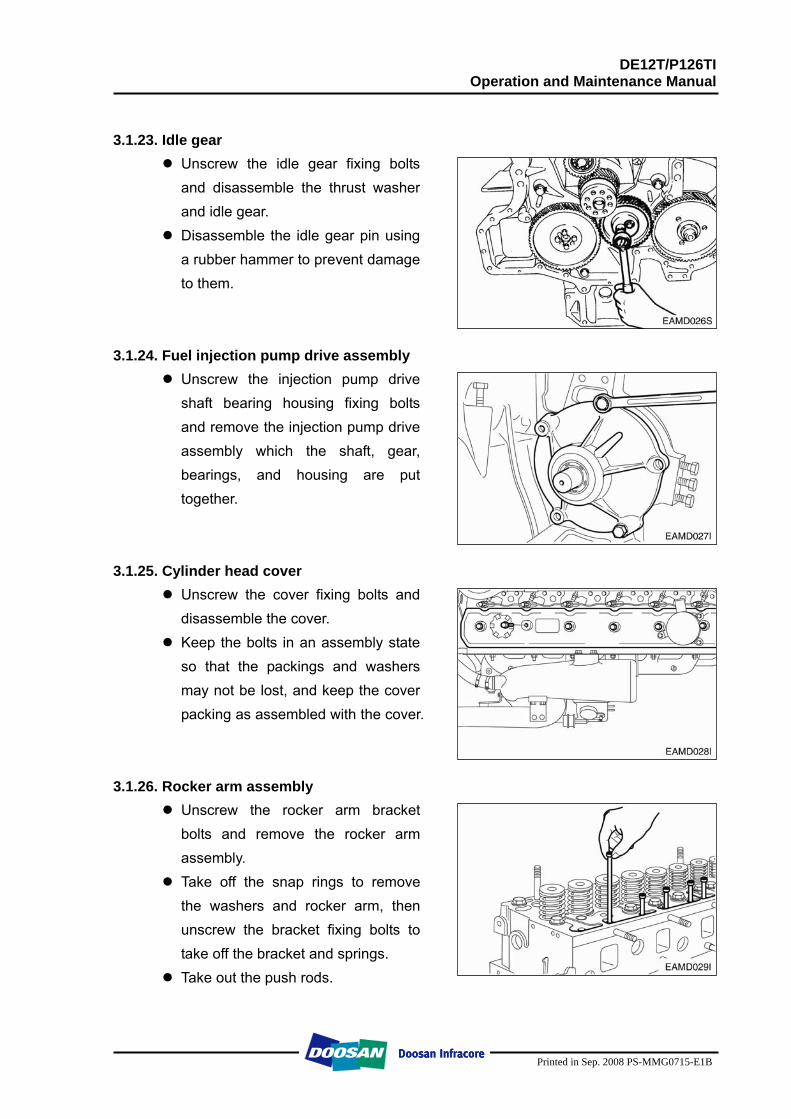
3.1.23. Idle gear
Unscrew the idle gear fixing bolts and disassemble the thrust washer and idle gear.
Disassemble the idle gear pin using a rubber hammer to prevent damage to them.
3.1.24. Fuel injection pump drive assembly
Unscrew the injection pump drive shaft bearing housing fixing bolts and remove the injection pump drive assembly which the shaft, gear, bearings, and housing are put together.
3.1.25. Cylinder head cover
Unscrew the cover fixing bolts and disassemble the cover.
Keep the bolts in an assembly state so that the packings and washers may not be lost, and keep the cover packing as assembled with the cover.
3.1.26. Rocker arm assembly
Unscrew the rocker arm bracket bolts and remove the rocker arm assembly.
Take off the snap rings to remove the washers and rocker arm, then unscrew the bracket fixing bolts to take off the bracket and springs.
Take out the push rods.
DE12T/P126TI Operation and Maintenance Manual
Printed in Sep. 2008 PS-MMG0715-E1B
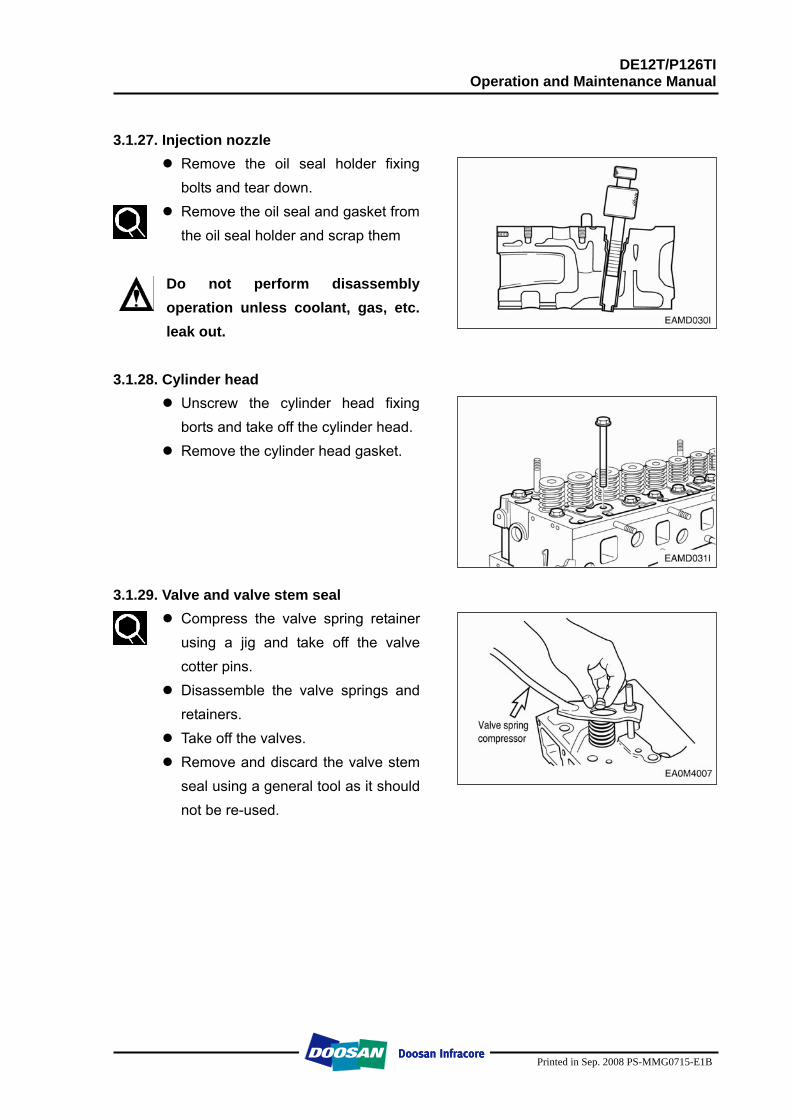
3.1.27. Injection nozzle
Remove the oil seal holder fixing bolts and tear down.
Remove the oil seal and gasket from the oil seal holder and scrap them
Do not perform disassembly operation unless coolant, gas, etc. leak out.
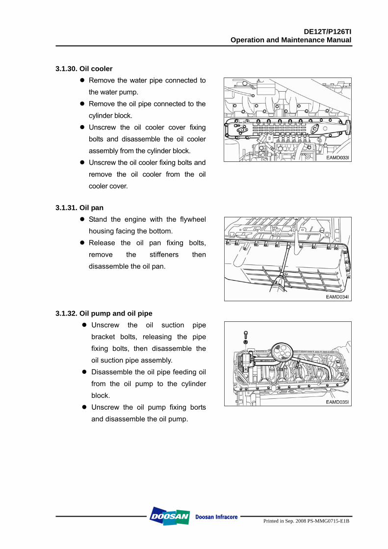
3.1.28. Cylinder head
Unscrew the cylinder head fixing borts and take off the cylinder head.
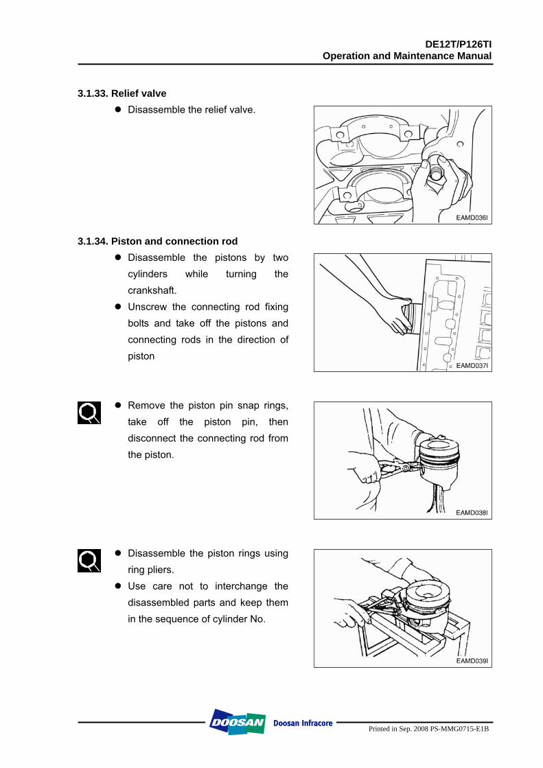
Remove the cylinder head gasket. 3.1.29. Valve and valve stem seal
Compress the valve spring retainer using a jig and take off the valve cotter pins.
Disassemble the valve springs and retainers.
Take off the valves. Remove and discard the valve stem seal using a general tool as it should not be re-used.
DE12T/P126TI Operation and Maintenance Manual
Printed in Sep. 2008 PS-MMG0715-E1B
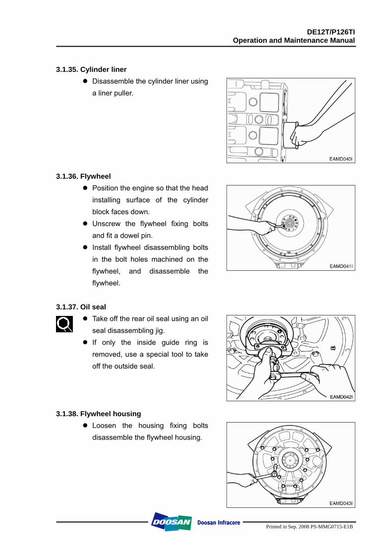
3.1.30. Oil cooler
Remove the water pipe connected to the water pump.
Remove the oil pipe connected to the cylinder block.
Unscrew the oil cooler cover fixing bolts and disassemble the oil cooler assembly from the cylinder block.
Unscrew the oil cooler fixing bolts and remove the oil cooler from the oil cooler cover.
3.1.31. Oil pan
Stand the engine with the flywheel housing facing the bottom.
Release the oil pan fixing bolts, remove the stiffeners then disassemble the oil pan.
3.1.32. Oil pump and oil pipe
Unscrew the oil suction pipe bracket bolts, releasing the pipe fixing bolts, then disassemble the oil suction pipe assembly.
Disassemble the oil pipe feeding oil from the oil pump to the cylinder block.
Unscrew the oil pump fixing borts and disassemble the oil pump.
DE12T/P126TI Operation and Maintenance Manual
Printed in Sep. 2008 PS-MMG0715-E1B
3.1.33. Relief valve
Disassemble the relief valve. 3.1.34. Piston and connection rod
Disassemble the pistons by two cylinders while turning the crankshaft.
Unscrew the connecting rod fixing bolts and take off the pistons and connecting rods in the direction of piston
Remove the piston pin snap rings, take off the piston pin, then disconnect the connecting rod from the piston.
Disassemble the piston rings using ring pliers.
Use care not to interchange the disassembled parts and keep them in the sequence of cylinder No.
DE12T/P126TI Operation and Maintenance Manual
Printed in Sep. 2008 PS-MMG0715-E1B
3.1.35. Cylinder liner
Disassemble the cylinder liner using a liner puller.
3.1.36. Flywheel
Position the engine so that the head installing surface of the cylinder block faces down.
Unscrew the flywheel fixing bolts and fit a dowel pin.
Install flywheel disassembling bolts in the bolt holes machined on the flywheel, and disassemble the flywheel.
3.1.37. Oil seal
Take off the rear oil seal using an oil seal disassembling jig.
If only the inside guide ring is removed, use a special tool to take off the outside seal.
3.1.38. Flywheel housing
Loosen the housing fixing bolts disassemble the flywheel housing.
DE12T/P126TI Operation and Maintenance Manual
Printed in Sep. 2008 PS-MMG0715-E1B
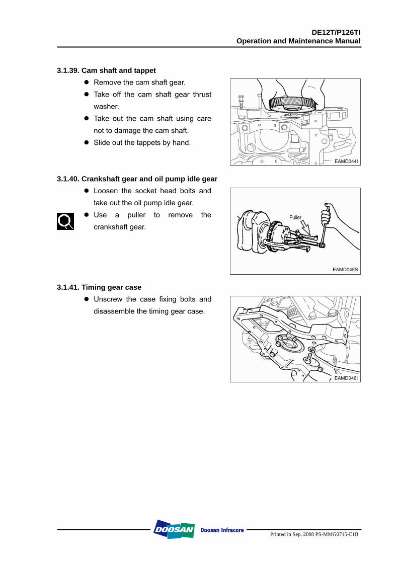
3.1.39. Cam shaft and tappet
Remove the cam shaft gear. Take off the cam shaft gear thrust
washer. Take out the cam shaft using care
not to damage the cam shaft. Slide out the tappets by hand.
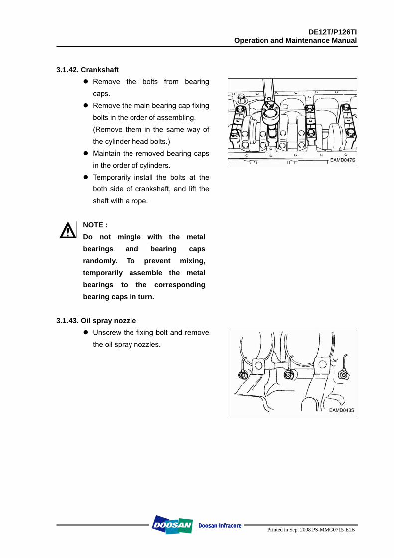
3.1.40. Crankshaft gear and oil pump idle gear
Loosen the socket head bolts and take out the oil pump idle gear.
Use a puller to remove the crankshaft gear.
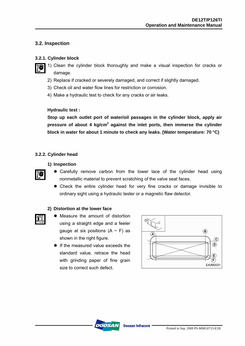
3.1.41. Timing gear case
Unscrew the case fixing bolts and disassemble the timing gear case.
DE12T/P126TI Operation and Maintenance Manual
Printed in Sep. 2008 PS-MMG0715-E1B
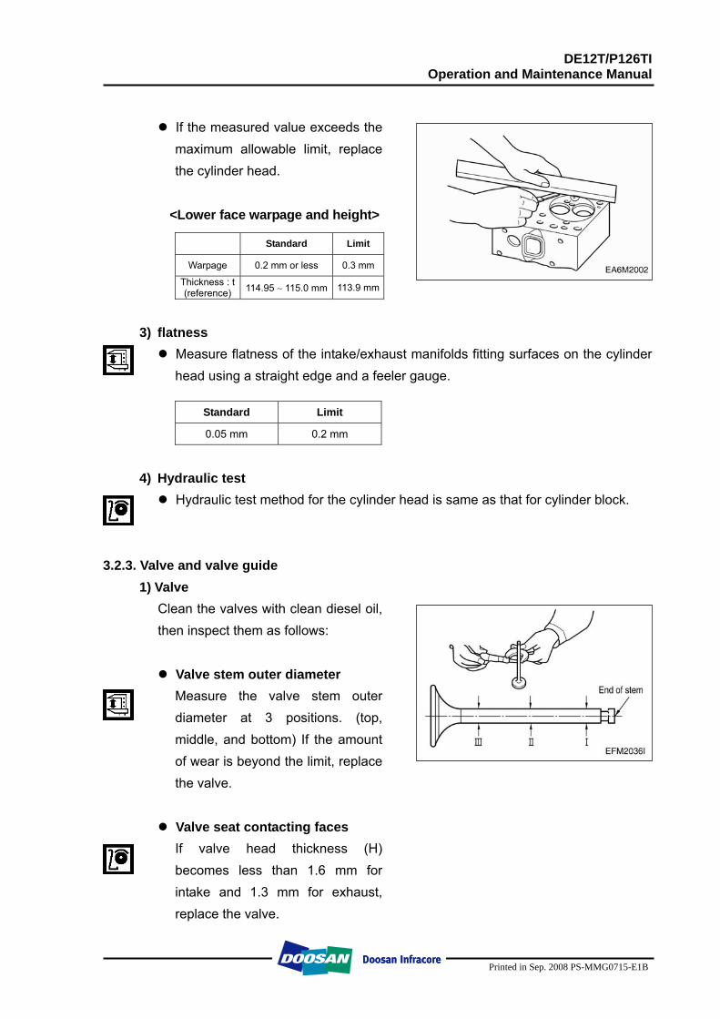
3.1.42. Crankshaft
Remove the bolts from bearing caps.
Remove the main bearing cap fixing bolts in the order of assembling. (Remove them in the same way of the cylinder head bolts.)
Maintain the removed bearing caps in the order of cylinders.
Temporarily install the bolts at the both side of crankshaft, and lift the shaft with a rope.
NOTE : Do not mingle with the metal bearings and bearing caps randomly. To prevent mixing, temporarily assemble the metal bearings to the corresponding bearing caps in turn.
3.1.43. Oil spray nozzle
Unscrew the fixing bolt and remove the oil spray nozzles.
DE12T/P126TI Operation and Maintenance Manual
Printed in Sep. 2008 PS-MMG0715-E1B
3.2. Inspection 3.2.1. Cylinder block
1) Clean the cylinder block thoroughly and make a visual inspection for cracks or damage.
2) Replace if cracked or severely damaged, and correct if slightly damaged. 3) Check oil and water flow lines for restriction or corrosion. 4) Make a hydraulic test to check for any cracks or air leaks.
Hydraulic test : Stop up each outlet port of water/oil passages in the cylinder block, apply air pressure of about 4 kg/cm2 against the inlet ports, then immerse the cylinder block in water for about 1 minute to check any leaks. (Water temperature: 70 °C)
3.2.2. Cylinder head
1) Inspection Carefully remove carbon from the lower lace of the cylinder head using nonmetallic material to prevent scratching of the valve seat faces.
Check the entire cylinder head for very fine cracks or damage invisible to ordinary sight using a hydraulic tester or a magnetic flaw detector.
2) Distortion at the lower face
Measure the amount of distortion using a straight edge and a feeler gauge at six positions (A ~ F) as shown in the right figure.
If the measured value exceeds the standard value, retrace the head with grinding paper of fine grain size to correct such defect.
DE12T/P126TI Operation and Maintenance Manual
Printed in Sep. 2008 PS-MMG0715-E1B
If the measured value exceeds the maximum allowable limit, replace the cylinder head.
<Lower face warpage and height>
Standard Limit
Warpage 0.2 mm or less 0.3 mm
Thickness : t (reference) 114.95 ∼ 115.0 mm 113.9 mm
3) flatness
Measure flatness of the intake/exhaust manifolds fitting surfaces on the cylinder head using a straight edge and a feeler gauge.
Standard Limit
0.05 mm 0.2 mm
4) Hydraulic test
Hydraulic test method for the cylinder head is same as that for cylinder block. 3.2.3. Valve and valve guide
1) Valve Clean the valves with clean diesel oil, then inspect them as follows:
Valve stem outer diameter Measure the valve stem outer diameter at 3 positions. (top, middle, and bottom) If the amount of wear is beyond the limit, replace the valve.
Valve seat contacting faces If valve head thickness (H) becomes less than 1.6 mm for intake and 1.3 mm for exhaust, replace the valve.
DE12T/P126TI Operation and Maintenance Manual
Printed in Sep. 2008 PS-MMG0715-E1B
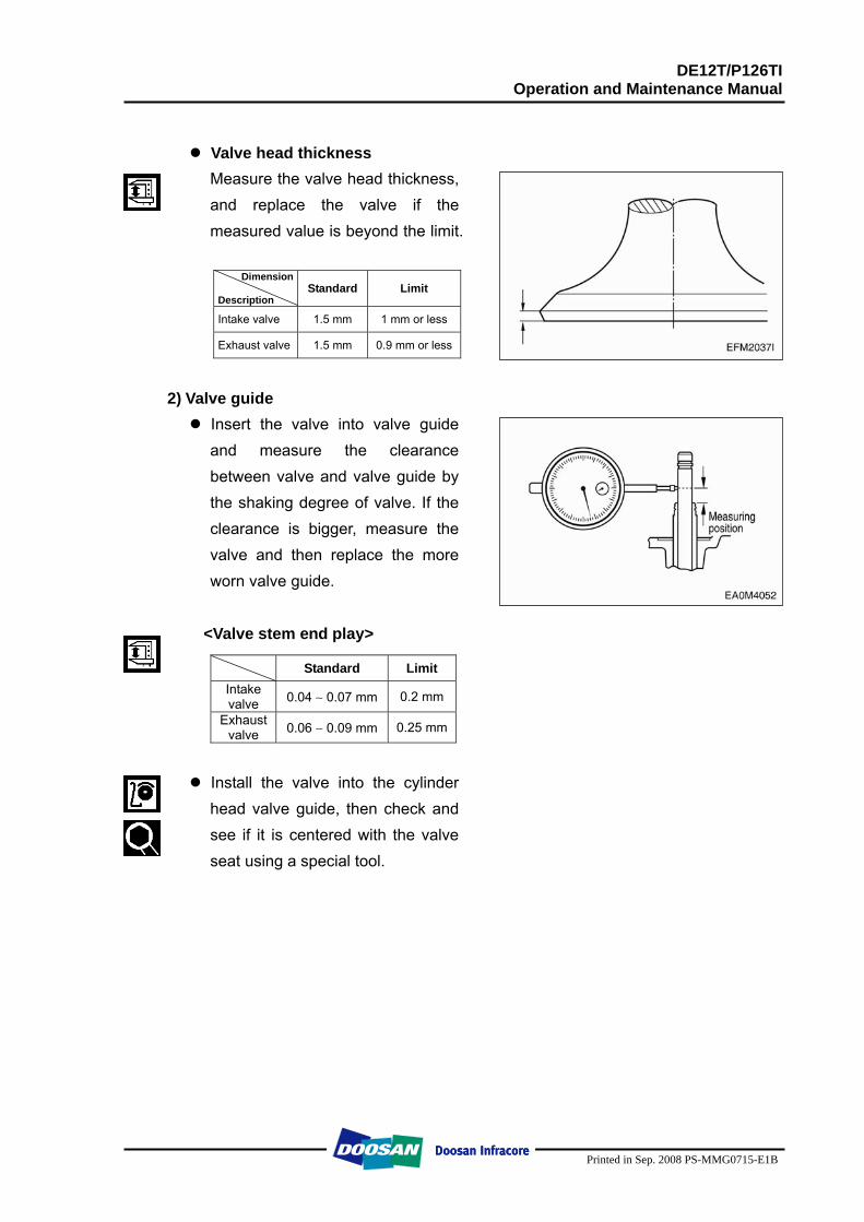
Valve head thickness Measure the valve head thickness, and replace the valve if the measured value is beyond the limit.
Dimension
Description Standard Limit
Intake valve 1.5 mm 1 mm or less
Exhaust valve 1.5 mm 0.9 mm or less
2) Valve guide
Insert the valve into valve guide and measure the clearance between valve and valve guide by the shaking degree of valve. If the clearance is bigger, measure the valve and then replace the more worn valve guide.
<Valve stem end play>
Standard Limit Intake valve 0.04 ∼ 0.07 mm 0.2 mm
Exhaust valve 0.06 ∼ 0.09 mm 0.25 mm
Install the valve into the cylinder head valve guide, then check and see if it is centered with the valve seat using a special tool.
DE12T/P126TI Operation and Maintenance Manual
Printed in Sep. 2008 PS-MMG0715-E1B
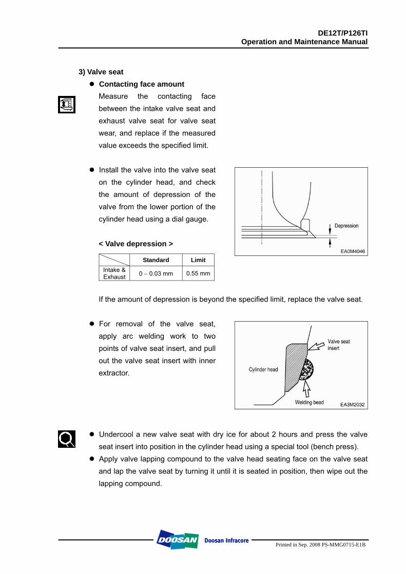
3) Valve seat
Contacting face amount Measure the contacting face between the intake valve seat and exhaust valve seat for valve seat wear, and replace if the measured value exceeds the specified limit.
Install the valve into the valve seat on the cylinder head, and check the amount of depression of the valve from the lower portion of the cylinder head using a dial gauge.
< Valve depression >
Standard Limit Intake & Exhaust 0 ∼ 0.03 mm 0.55 mm
If the amount of depression is beyond the specified limit, replace the valve seat.
For removal of the valve seat, apply arc welding work to two points of valve seat insert, and pull out the valve seat insert with inner extractor.
Undercool a new valve seat with dry ice for about 2 hours and press the valve seat insert into position in the cylinder head using a special tool (bench press).
Apply valve lapping compound to the valve head seating face on the valve seat and lap the valve seat by turning it until it is seated in position, then wipe out the lapping compound.
DE12T/P126TI Operation and Maintenance Manual
Printed in Sep. 2008 PS-MMG0715-E1B
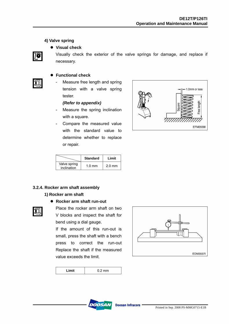
4) Valve spring
Visual check Visually check the exterior of the valve springs for damage, and replace if necessary.
Functional check - Measure free length and spring
tension with a valve spring tester. (Refer to appendix)
- Measure the spring inclination with a square.
- Compare the measured value with the standard value to determine whether to replace or repair.
Standard Limit
Valve spring inclination 1.0 mm 2.0 mm
3.2.4. Rocker arm shaft assembly 1) Rocker arm shaft
Rocker arm shaft run-out Place the rocker arm shaft on two V blocks and inspect the shaft for bend using a dial gauge. If the amount of this run-out is small, press the shaft with a bench press to correct the run-out Replace the shaft if the measured value exceeds the limit.
Limit 0.2 mm
DE12T/P126TI Operation and Maintenance Manual
Printed in Sep. 2008 PS-MMG0715-E1B
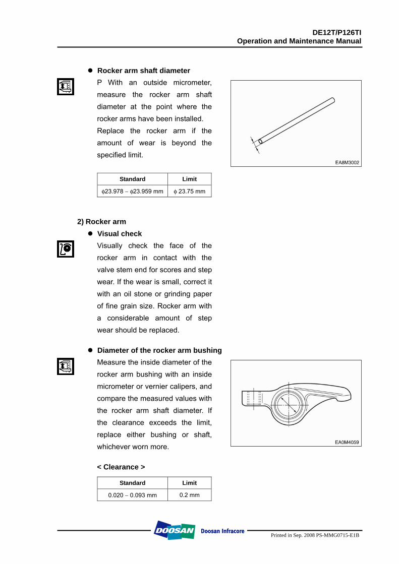
Rocker arm shaft diameter P With an outside micrometer, measure the rocker arm shaft diameter at the point where the rocker arms have been installed. Replace the rocker arm if the amount of wear is beyond the specified limit.
Standard Limit
φ23.978 ∼ φ23.959 mm φ 23.75 mm
2) Rocker arm Visual check Visually check the face of the rocker arm in contact with the valve stem end for scores and step wear. If the wear is small, correct it with an oil stone or grinding paper of fine grain size. Rocker arm with a considerable amount of step wear should be replaced.
Diameter of the rocker arm bushing Measure the inside diameter of the rocker arm bushing with an inside micrometer or vernier calipers, and compare the measured values with the rocker arm shaft diameter. If the clearance exceeds the limit, replace either bushing or shaft, whichever worn more. < Clearance >
Standard Limit
0.020 ∼ 0.093 mm 0.2 mm
DE12T/P126TI Operation and Maintenance Manual
Printed in Sep. 2008 PS-MMG0715-E1B
3) Tappet and push rod
Clearance Measure the clearance of the tappet and tappet holes of the cylinder block. If the value is beyond the specified limit, replace tappets.
Standard Limit
0.035 ∼ 0.077 mm 0.15 mm
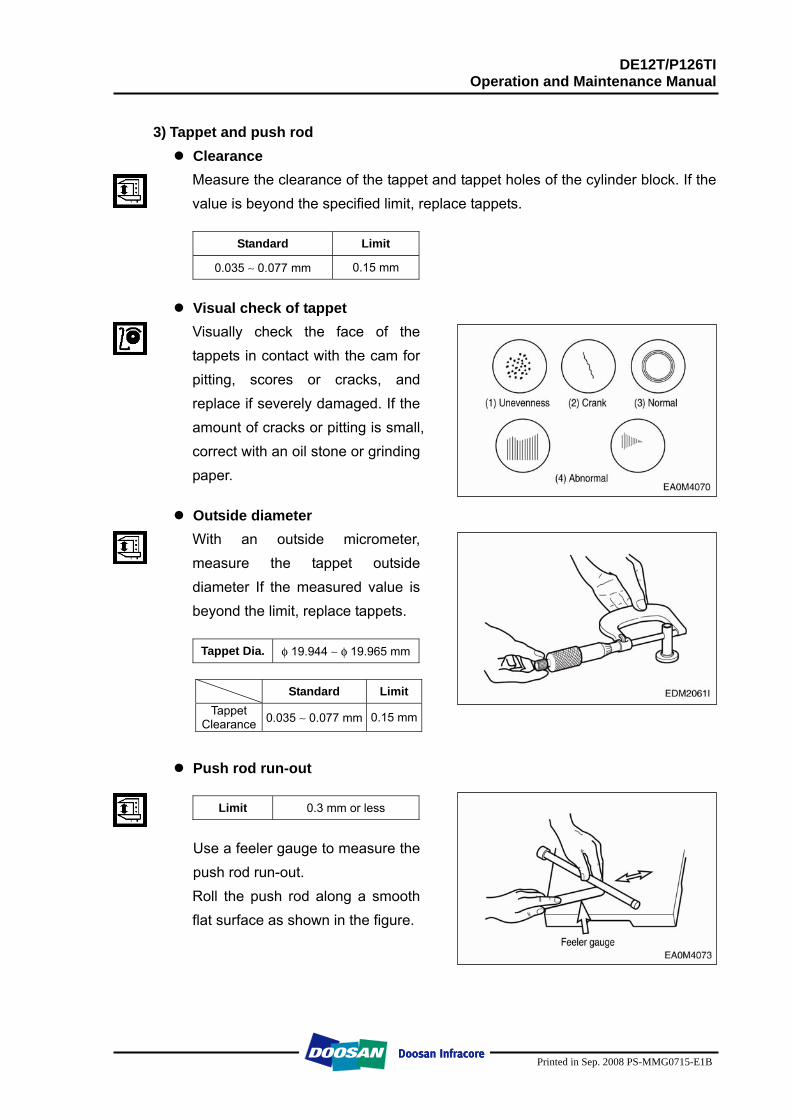
Visual check of tappet Visually check the face of the tappets in contact with the cam for pitting, scores or cracks, and replace if severely damaged. If the amount of cracks or pitting is small, correct with an oil stone or grinding paper.
Outside diameter With an outside micrometer, measure the tappet outside diameter If the measured value is beyond the limit, replace tappets.
Tappet Dia. φ 19.944 ∼ φ 19.965 mm
Standard Limit
Tappet Clearance 0.035 ∼ 0.077 mm 0.15 mm
Push rod run-out
Limit 0.3 mm or less
Use a feeler gauge to measure the push rod run-out. Roll the push rod along a smooth flat surface as shown in the figure.
DE12T/P126TI Operation and Maintenance Manual
Printed in Sep. 2008 PS-MMG0715-E1B
3.2.5. Cam shaft
1) Cam Cam lobe height
Standard Limit
Intake φ59.86 ∼ φ59.88 mm Cam lobe height (C) Exhaust φ59.86 ∼ φ59.88 mm
φ49.5 mm
Cam journal diameter (A,B) φ59.86 ∼ φ59.88 mm φ59.52 mm
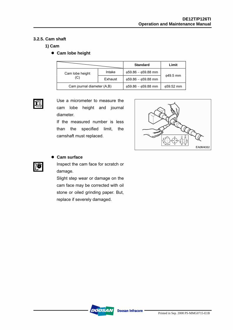
Use a micrometer to measure the cam lobe height and journal diameter. If the measured number is less than the specified limit, the camshaft must replaced.
Cam surface Inspect the cam face for scratch or damage. Slight step wear or damage on the cam face may be corrected with oil stone or oiled grinding paper. But, replace if severely damaged.
DE12T/P126TI Operation and Maintenance Manual
Printed in Sep. 2008 PS-MMG0715-E1B
2) Cam shaft
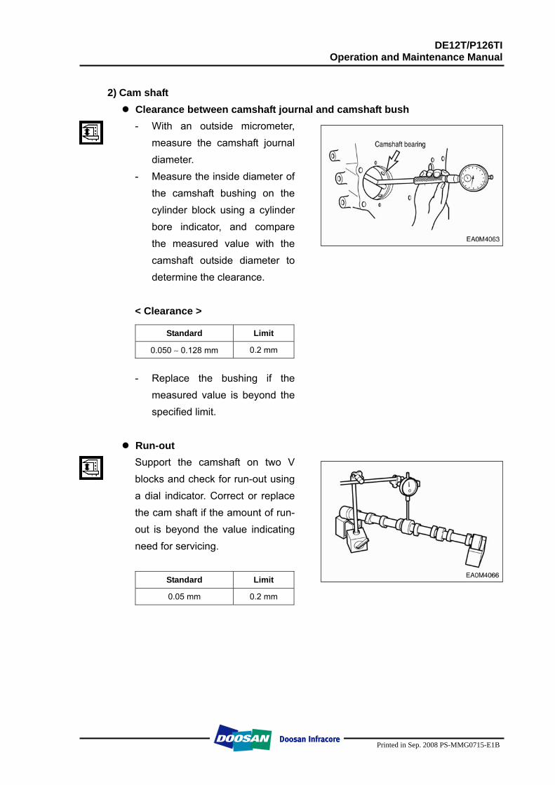
Clearance between camshaft journal and camshaft bush - With an outside micrometer,
measure the camshaft journal diameter.
- Measure the inside diameter of the camshaft bushing on the cylinder block using a cylinder bore indicator, and compare the measured value with the camshaft outside diameter to determine the clearance.
< Clearance >
Standard Limit
0.050 ∼ 0.128 mm 0.2 mm
- Replace the bushing if the
measured value is beyond the specified limit.
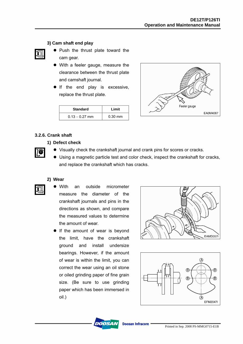
Run-out Support the camshaft on two V blocks and check for run-out using a dial indicator. Correct or replace the cam shaft if the amount of run-out is beyond the value indicating need for servicing.
Standard Limit
0.05 mm 0.2 mm
DE12T/P126TI Operation and Maintenance Manual
Printed in Sep. 2008 PS-MMG0715-E1B
3) Cam shaft end play
Push the thrust plate toward the cam gear.
With a feeler gauge, measure the clearance between the thrust plate and camshaft journal.
If the end play is excessive, replace the thrust plate.
Standard Limit
0.13 ∼ 0.27 mm 0.30 mm
3.2.6. Crank shaft 1) Defect check
Visually check the crankshaft journal and crank pins for scores or cracks. Using a magnetic particle test and color check, inspect the crankshaft for cracks, and replace the crankshaft which has cracks.
2) Wear
With an outside micrometer measure the diameter of the crankshaft journals and pins in the directions as shown, and compare the measured values to determine the amount of wear.
If the amount of wear is beyond the limit, have the crankshaft ground and install undersize bearings. However, if the amount of wear is within the limit, you can correct the wear using an oil stone or oiled grinding paper of fine grain size. (Be sure to use grinding paper which has been immersed in oil.)
DE12T/P126TI Operation and Maintenance Manual
Printed in Sep. 2008 PS-MMG0715-E1B
Standard Limit
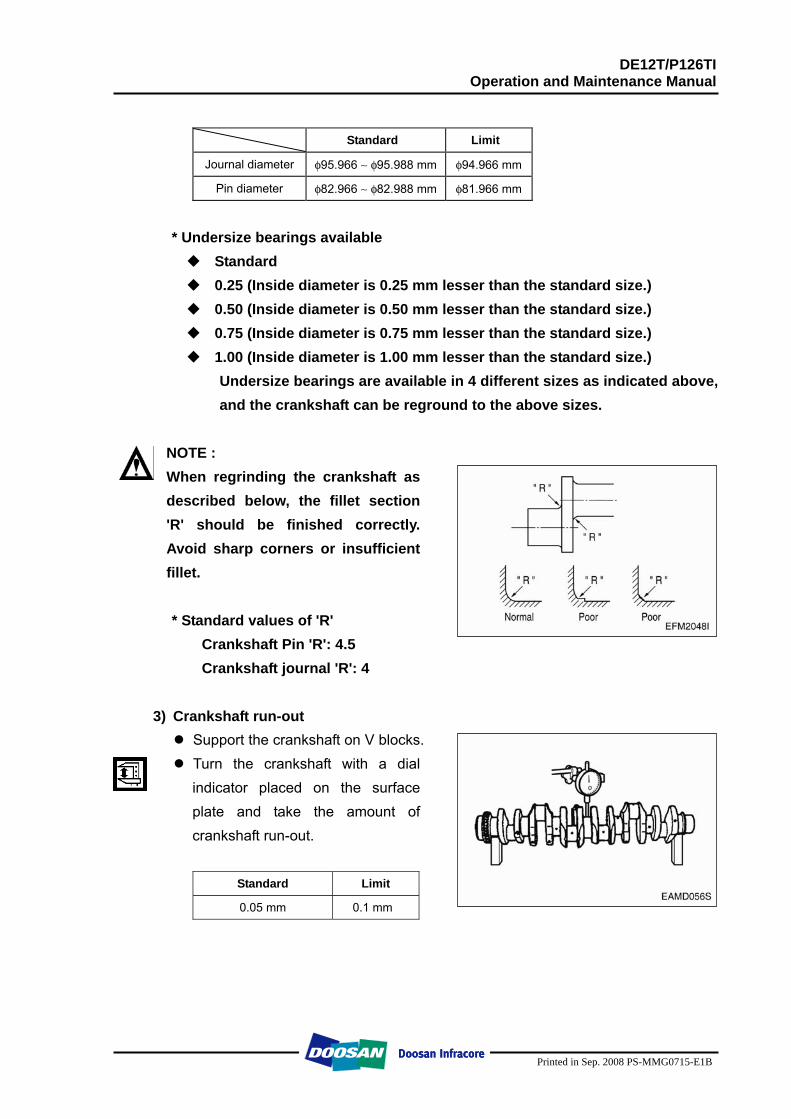
Journal diameter φ95.966 ∼ φ95.988 mm φ94.966 mm
Pin diameter φ82.966 ∼ φ82.988 mm φ81.966 mm
* Undersize bearings available
Standard 0.25 (Inside diameter is 0.25 mm lesser than the standard size.) 0.50 (Inside diameter is 0.50 mm lesser than the standard size.) 0.75 (Inside diameter is 0.75 mm lesser than the standard size.) 1.00 (Inside diameter is 1.00 mm lesser than the standard size.)
Undersize bearings are available in 4 different sizes as indicated above, and the crankshaft can be reground to the above sizes.
NOTE : When regrinding the crankshaft as described below, the fillet section 'R' should be finished correctly. Avoid sharp corners or insufficient fillet.
* Standard values of 'R'
� Crankshaft Pin 'R': 4.5 � Crankshaft journal 'R': 4
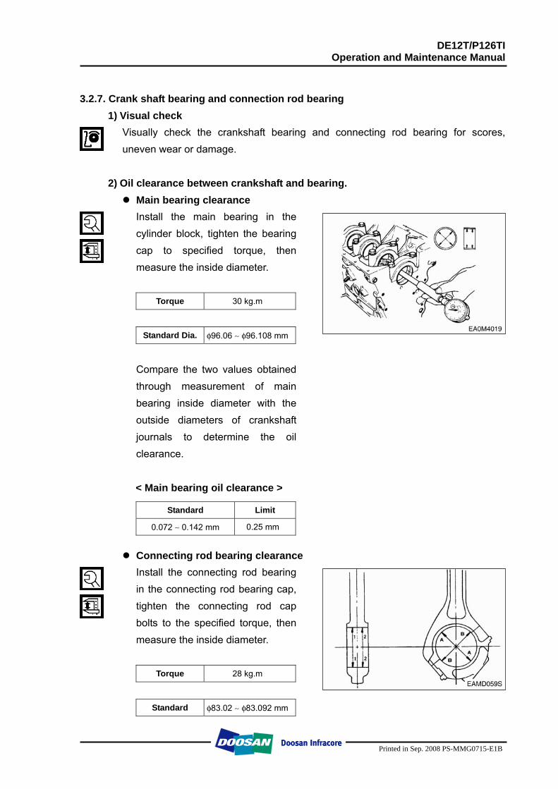
3) Crankshaft run-out Support the crankshaft on V blocks. Turn the crankshaft with a dial indicator placed on the surface plate and take the amount of crankshaft run-out.
Standard Limit
0.05 mm 0.1 mm
DE12T/P126TI Operation and Maintenance Manual
Printed in Sep. 2008 PS-MMG0715-E1B
3.2.7. Crank shaft bearing and connection rod bearing
1) Visual check Visually check the crankshaft bearing and connecting rod bearing for scores, uneven wear or damage.
2) Oil clearance between crankshaft and bearing.
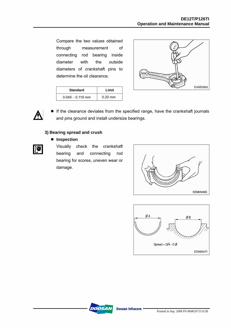
Main bearing clearance Install the main bearing in the cylinder block, tighten the bearing cap to specified torque, then measure the inside diameter.
Torque 30 kg.m
Standard Dia. φ96.06 ∼ φ96.108 mm
Compare the two values obtained through measurement of main bearing inside diameter with the outside diameters of crankshaft journals to determine the oil clearance. < Main bearing oil clearance >
Standard Limit
0.072 ∼ 0.142 mm 0.25 mm
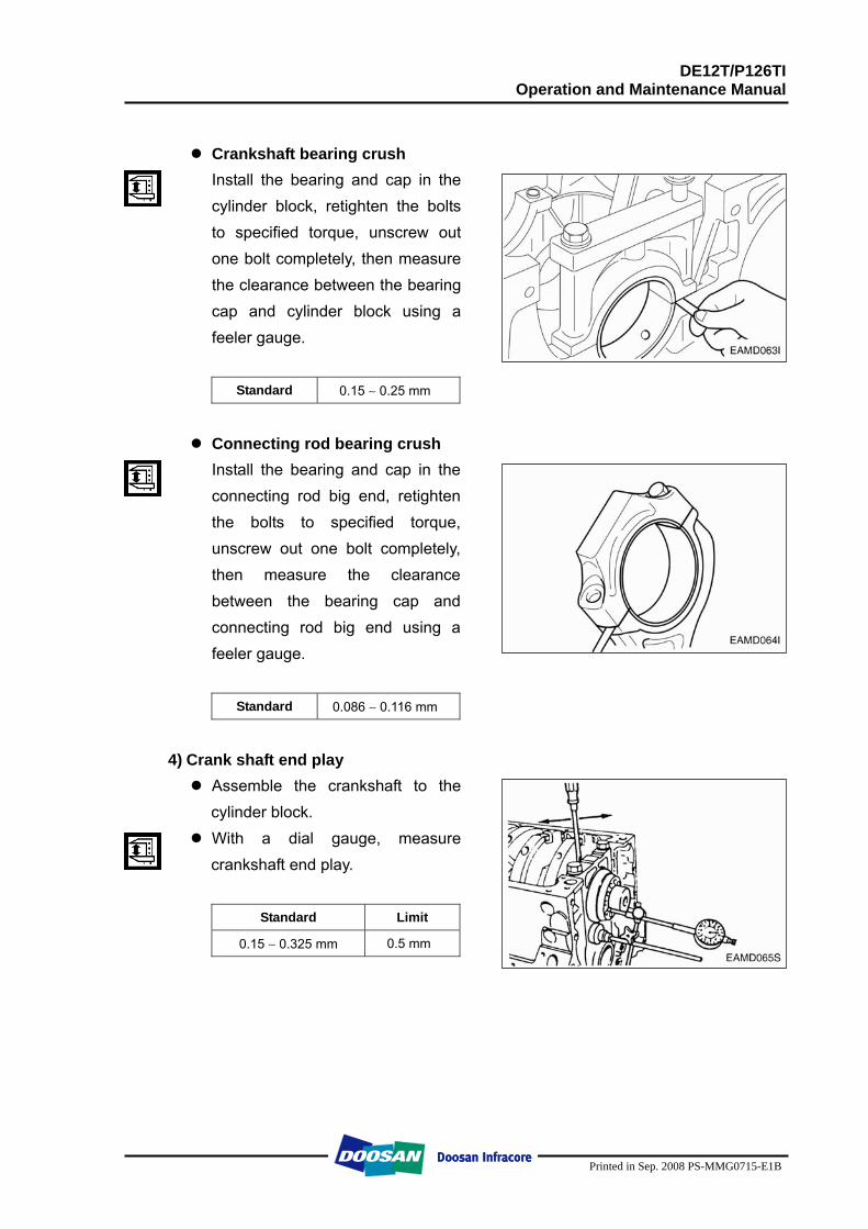
Connecting rod bearing clearance
Install the connecting rod bearing in the connecting rod bearing cap, tighten the connecting rod cap bolts to the specified torque, then measure the inside diameter.
Torque 28 kg.m
Standard φ83.02 ∼ φ83.092 mm
DE12T/P126TI Operation and Maintenance Manual
Printed in Sep. 2008 PS-MMG0715-E1B
Compare the two values obtained through measurement of connecting rod bearing inside diameter with the outside diameters of crankshaft pins to determine the oil clearance.
Standard Limit
0.049 ∼ 0.119 mm 0.20 mm
If the clearance deviates from the specified range, have the crankshaft journals and pins ground and install undersize bearings.
3) Bearing spread and crush Inspection
Visually check the crankshaft bearing and connecting rod bearing for scores, uneven wear or damage.
DE12T/P126TI Operation and Maintenance Manual
Printed in Sep. 2008 PS-MMG0715-E1B
Crankshaft bearing crush
Install the bearing and cap in the cylinder block, retighten the bolts to specified torque, unscrew out one bolt completely, then measure the clearance between the bearing cap and cylinder block using a feeler gauge.
Standard 0.15 ∼ 0.25 mm
Connecting rod bearing crush
Install the bearing and cap in the connecting rod big end, retighten the bolts to specified torque, unscrew out one bolt completely, then measure the clearance between the bearing cap and connecting rod big end using a feeler gauge.
Standard 0.086 ∼ 0.116 mm
4) Crank shaft end play
Assemble the crankshaft to the cylinder block.
With a dial gauge, measure crankshaft end play.
Standard Limit
0.15 ∼ 0.325 mm 0.5 mm
DE12T/P126TI Operation and Maintenance Manual
Printed in Sep. 2008 PS-MMG0715-E1B
3.2.8. Piston
1) Visual check Visually check the pistons for cracks, scuff or wear, paying particular attention to the ring groove.
2) Clearance between the piston and cylinder liner
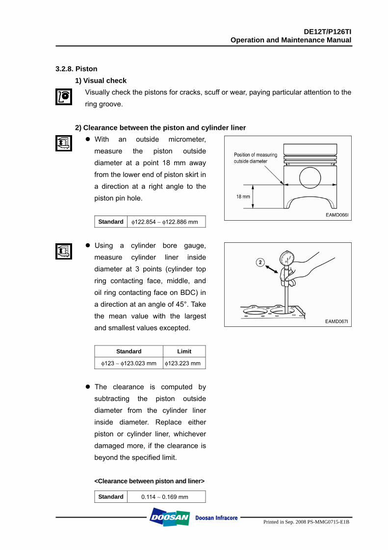
With an outside micrometer, measure the piston outside diameter at a point 18 mm away from the lower end of piston skirt in a direction at a right angle to the piston pin hole.
Standard φ122.854 ∼ φ122.886 mm
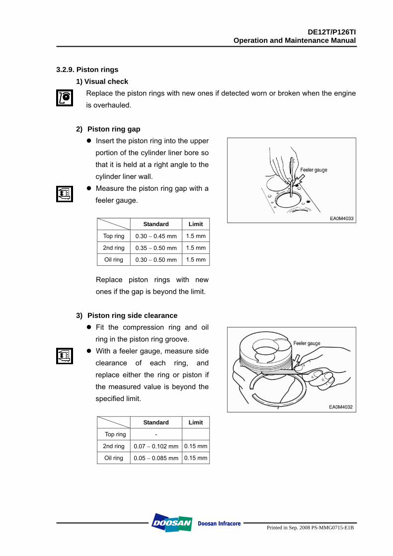
Using a cylinder bore gauge, measure cylinder liner inside diameter at 3 points (cylinder top ring contacting face, middle, and oil ring contacting face on BDC) in a direction at an angle of 45°. Take the mean value with the largest and smallest values excepted.
Standard Limit
φ123 ∼ φ123.023 mm φ123.223 mm
The clearance is computed by subtracting the piston outside diameter from the cylinder liner inside diameter. Replace either piston or cylinder liner, whichever damaged more, if the clearance is beyond the specified limit.
<Clearance between piston and liner>
Standard 0.114 ∼ 0.169 mm
DE12T/P126TI Operation and Maintenance Manual
Printed in Sep. 2008 PS-MMG0715-E1B
3.2.9. Piston rings
1) Visual check Replace the piston rings with new ones if detected worn or broken when the engine is overhauled.
2) Piston ring gap
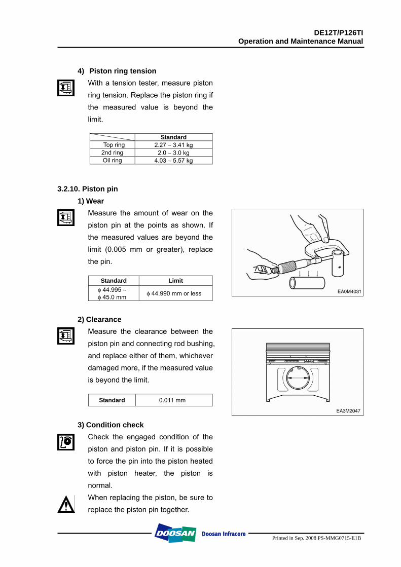
Insert the piston ring into the upper portion of the cylinder liner bore so that it is held at a right angle to the cylinder liner wall.
Measure the piston ring gap with a feeler gauge.
Standard Limit
Top ring 0.30 ∼ 0.45 mm 1.5 mm
2nd ring 0.35 ∼ 0.50 mm 1.5 mm
Oil ring 0.30 ∼ 0.50 mm 1.5 mm
Replace piston rings with new ones if the gap is beyond the limit.
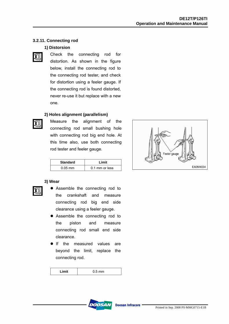
3) Piston ring side clearance Fit the compression ring and oil ring in the piston ring groove.
With a feeler gauge, measure side clearance of each ring, and replace either the ring or piston if the measured value is beyond the specified limit.
Standard Limit
Top ring -
2nd ring 0.07 ∼ 0.102 mm 0.15 mm
Oil ring 0.05 ∼ 0.085 mm 0.15 mm
DE12T/P126TI Operation and Maintenance Manual
Printed in Sep. 2008 PS-MMG0715-E1B
4) Piston ring tension
With a tension tester, measure piston ring tension. Replace the piston ring if the measured value is beyond the limit.
Standard
Top ring 2.27 ∼ 3.41 kg 2nd ring 2.0 ∼ 3.0 kg Oil ring 4.03 ∼ 5.57 kg
3.2.10. Piston pin 1) Wear
Measure the amount of wear on the piston pin at the points as shown. If the measured values are beyond the limit (0.005 mm or greater), replace the pin.
Standard Limit
φ 44.995 ∼ φ 45.0 mm φ 44.990 mm or less
2) Clearance
Measure the clearance between the piston pin and connecting rod bushing, and replace either of them, whichever damaged more, if the measured value is beyond the limit.
Standard 0.011 mm
3) Condition check
Check the engaged condition of the piston and piston pin. If it is possible to force the pin into the piston heated with piston heater, the piston is normal. When replacing the piston, be sure to replace the piston pin together.
DE12T/P126TI Operation and Maintenance Manual
Printed in Sep. 2008 PS-MMG0715-E1B
3.2.11. Connecting rod
1) Distorsion Check the connecting rod for distortion. As shown in the figure below, install the connecting rod to the connecting rod tester, and check for distortion using a feeler gauge. If the connecting rod is found distorted, never re-use it but replace with a new one.
2) Holes alignment (parallelism)
Measure the alignment of the connecting rod small bushing hole with connecting rod big end hole. At this time also, use both connecting rod tester and feeler gauge.
Standard Limit 0.05 mm 0.1 mm or less
3) Wear
Assemble the connecting rod to the crankshaft and measure connecting rod big end side clearance using a feeler gauge.
Assemble the connecting rod to the piston and measure connecting rod small end side clearance.
If the measured values are beyond the limit, replace the connecting rod.
Limit 0.5 mm
DE12T/P126TI Operation and Maintenance Manual
Printed in Sep. 2008 PS-MMG0715-E1B
3.3. Reassembly 3.3.1. General precautions
Wash clean all the disassembled parts, particularly oil and water ports, using compressed air, then check that they are free from restrictions.
Arrange the general and special tools in order for engine assembly operation. To wet each sliding part, prepare the clean engine oil. Prepare service materials such as sealant, gaskets, etc. Discard used gaskets, seal rings, and consumable parts, and replace with new
ones. Apply only the specified torque for bolts in the specified tightening order and
avoid over-tightening. Be sure to check that all the engine parts operate smoothly after being
reassembled. Check the bolts for looseness after preliminary reassembly. After completing the engine reassembly operation, check if there is missing parts
or shortage of parts. Keep your hands clean during the working.
3.3.2. Cylinder block
Cover the floor of the workshop with wood plate or thick paper to prevent damage to the cylinder head and place the cylinder block with the head fitting surface facing downward.
3.3.3. Oil spray nozzle
Tighten and assemble the oil spray nozzle flange with fixing bolts using the spray nozzle jig.
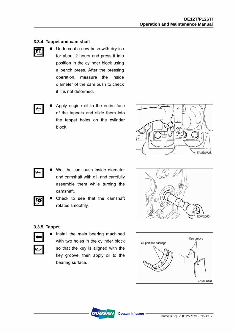
DE12T/P126TI Operation and Maintenance Manual
Printed in Sep. 2008 PS-MMG0715-E1B
3.3.4. Tappet and cam shaft
Undercool a new bush with dry ice for about 2 hours and press it into position in the cylinder block using a bench press. After the pressing operation, measure the inside diameter of the cam bush to check if it is not deformed.
Apply engine oil to the entire face
of the tappets and slide them into the tappet holes on the cylinder block.
Wet the cam bush inside diameter and camshaft with oil, and carefully assemble them while turning the camshaft.
Check to see that the camshaft rotates smoothly.
3.3.5. Tappet
Install the main bearing machined with two holes in the cylinder block so that the key is aligned with the key groove, then apply oil to the bearing surface.
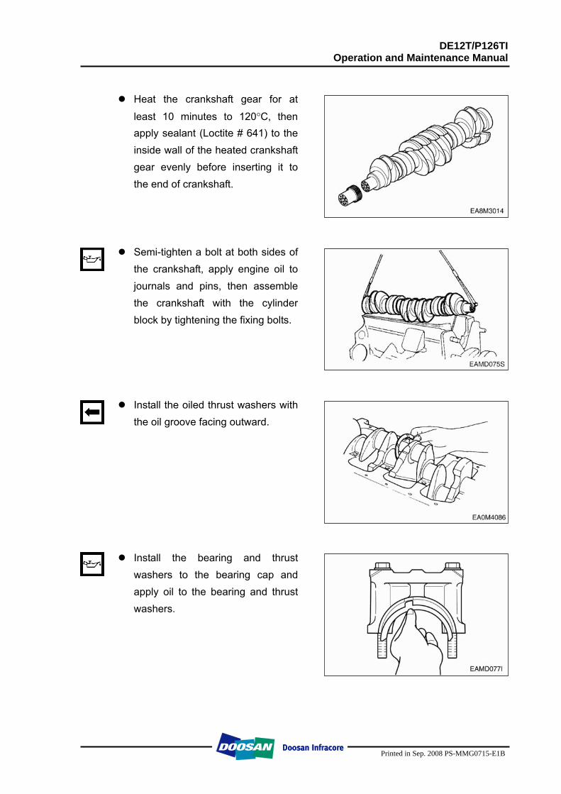
DE12T/P126TI Operation and Maintenance Manual
Printed in Sep. 2008 PS-MMG0715-E1B
Heat the crankshaft gear for at
least 10 minutes to 120°C, then apply sealant (Loctite # 641) to the inside wall of the heated crankshaft gear evenly before inserting it to the end of crankshaft.
Semi-tighten a bolt at both sides of the crankshaft, apply engine oil to journals and pins, then assemble the crankshaft with the cylinder block by tightening the fixing bolts.
Install the oiled thrust washers with the oil groove facing outward.
Install the bearing and thrust washers to the bearing cap and apply oil to the bearing and thrust washers.
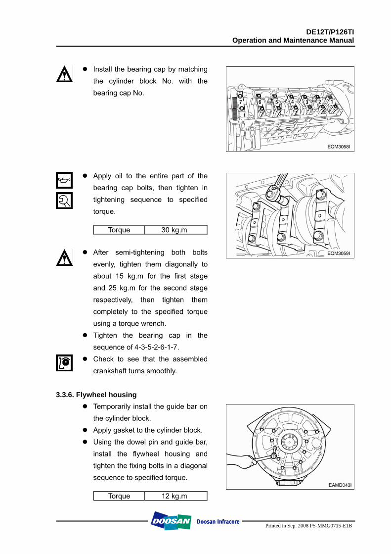
DE12T/P126TI Operation and Maintenance Manual
Printed in Sep. 2008 PS-MMG0715-E1B
Install the bearing cap by matching
the cylinder block No. with the bearing cap No.
Apply oil to the entire part of the bearing cap bolts, then tighten in tightening sequence to specified torque.
Torque 30 kg.m
After semi-tightening both bolts
evenly, tighten them diagonally to about 15 kg.m for the first stage and 25 kg.m for the second stage respectively, then tighten them completely to the specified torque using a torque wrench.
Tighten the bearing cap in the sequence of 4-3-5-2-6-1-7.
Check to see that the assembled crankshaft turns smoothly.
3.3.6. Flywheel housing
Temporarily install the guide bar on the cylinder block.
Apply gasket to the cylinder block. Using the dowel pin and guide bar,
install the flywheel housing and tighten the fixing bolts in a diagonal sequence to specified torque.
Torque 12 kg.m
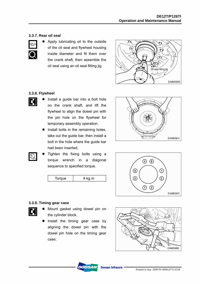
DE12T/P126TI Operation and Maintenance Manual
Printed in Sep. 2008 PS-MMG0715-E1B
3.3.7. Rear oil seal
Apply lubricating oil to the outside of the oil seal and flywheel housing inside diameter and fit them over the crank shaft, then assemble the oil seal using an oil seal fitting jig.
3.3.8. Flywheel Install a guide bar into a bolt hole
on the crank shaft, and lift the flywheel to align the dowel pin with the pin hole on the flywheel for temporary assembly operation.
Install bolts in the remaining holes, take out the guide bar, then install a bolt in the hole where the guide bar had been inserted.
Tighten the fixing bolts using a torque wrench in a diagonal sequence to specified torque.
Torque 4 kg.m
3.3.9. Timing gear case Mount gasket using dowel pin on
the cylinder block. Install the timing gear case by
aligning the dowel pin with the dowel pin hole on the timing gear case.
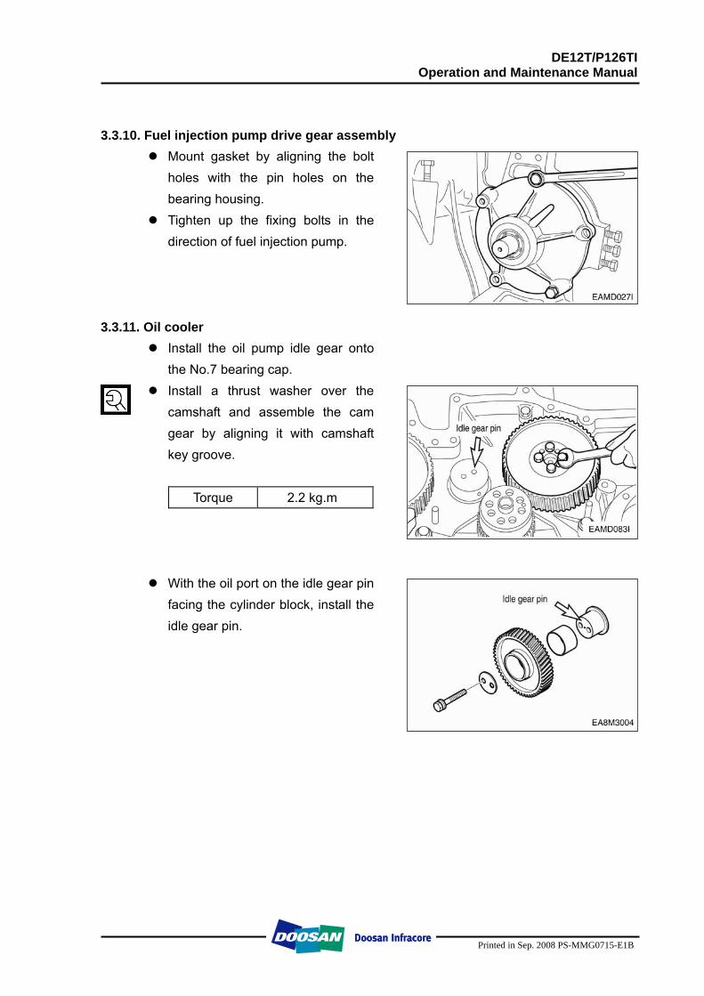
DE12T/P126TI Operation and Maintenance Manual
Printed in Sep. 2008 PS-MMG0715-E1B
3.3.10. Fuel injection pump drive gear assembly Mount gasket by aligning the bolt
holes with the pin holes on the bearing housing.
Tighten up the fixing bolts in the direction of fuel injection pump.
3.3.11. Oil cooler
Install the oil pump idle gear onto the No.7 bearing cap.
Install a thrust washer over the camshaft and assemble the cam gear by aligning it with camshaft key groove.
Torque 2.2 kg.m
With the oil port on the idle gear pin facing the cylinder block, install the idle gear pin.
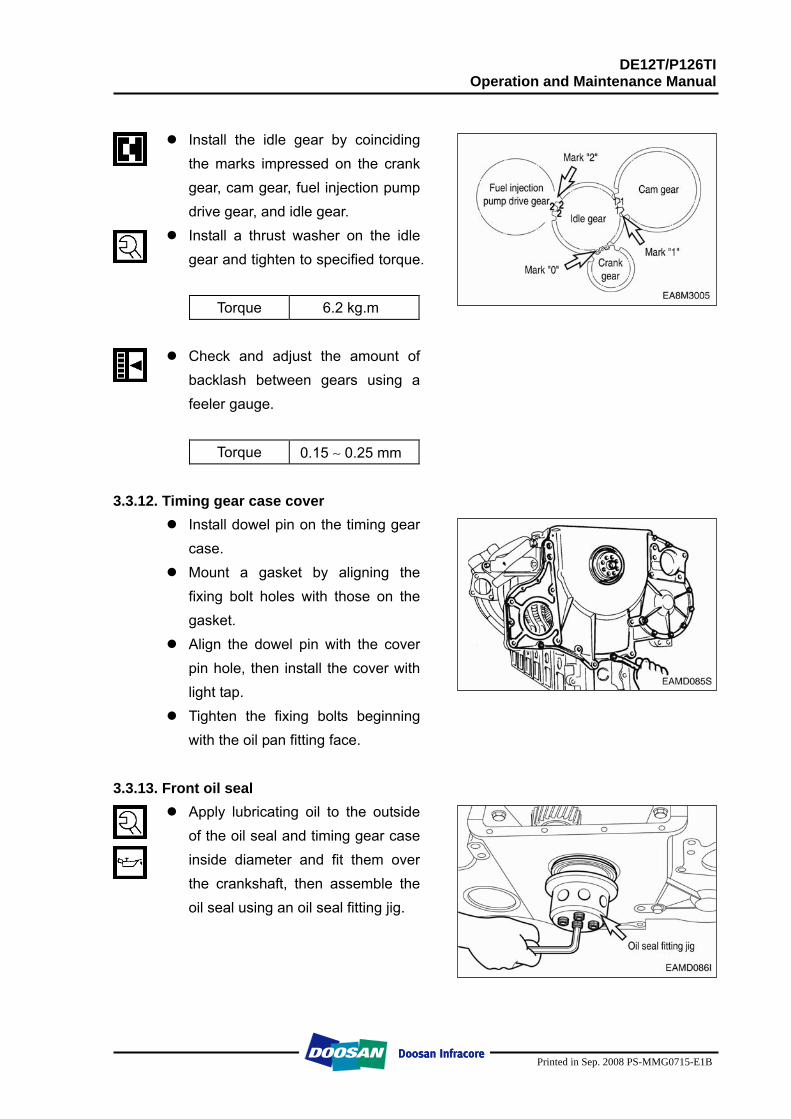
DE12T/P126TI Operation and Maintenance Manual
Printed in Sep. 2008 PS-MMG0715-E1B
Install the idle gear by coinciding
the marks impressed on the crank gear, cam gear, fuel injection pump drive gear, and idle gear.
Install a thrust washer on the idle gear and tighten to specified torque.
Torque 6.2 kg.m
Check and adjust the amount of
backlash between gears using a feeler gauge.
Torque 0.15 ∼ 0.25 mm 3.3.12. Timing gear case cover
Install dowel pin on the timing gear case.
Mount a gasket by aligning the fixing bolt holes with those on the gasket.
Align the dowel pin with the cover pin hole, then install the cover with light tap.
Tighten the fixing bolts beginning with the oil pan fitting face.
3.3.13. Front oil seal
Apply lubricating oil to the outside of the oil seal and timing gear case inside diameter and fit them over the crankshaft, then assemble the oil seal using an oil seal fitting jig.
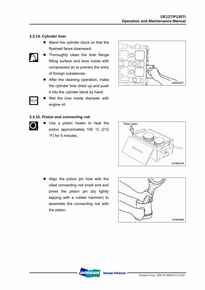
DE12T/P126TI Operation and Maintenance Manual
Printed in Sep. 2008 PS-MMG0715-E1B
3.3.14. Cylinder liner
Stand the cylinder block so that the flywheel faces downward.
Thoroughly clean the liner flange fitting surface and bore inside with compressed air to prevent the entry of foreign substances.
After the cleaning operation, make the cylinder liner dried up and push it into the cylinder block by hand.
Wet the liner inside diameter with engine oil.
3.3.15. Piston and connecting rod
Use a piston heater to heat the
piston approximately 100 °C (212 °F) for 5 minutes.
Align the piston pin hole with the oiled connecting rod small end and press the piston pin (by lightly tapping with a rubber hammer) to assemble the connecting rod with the piston.
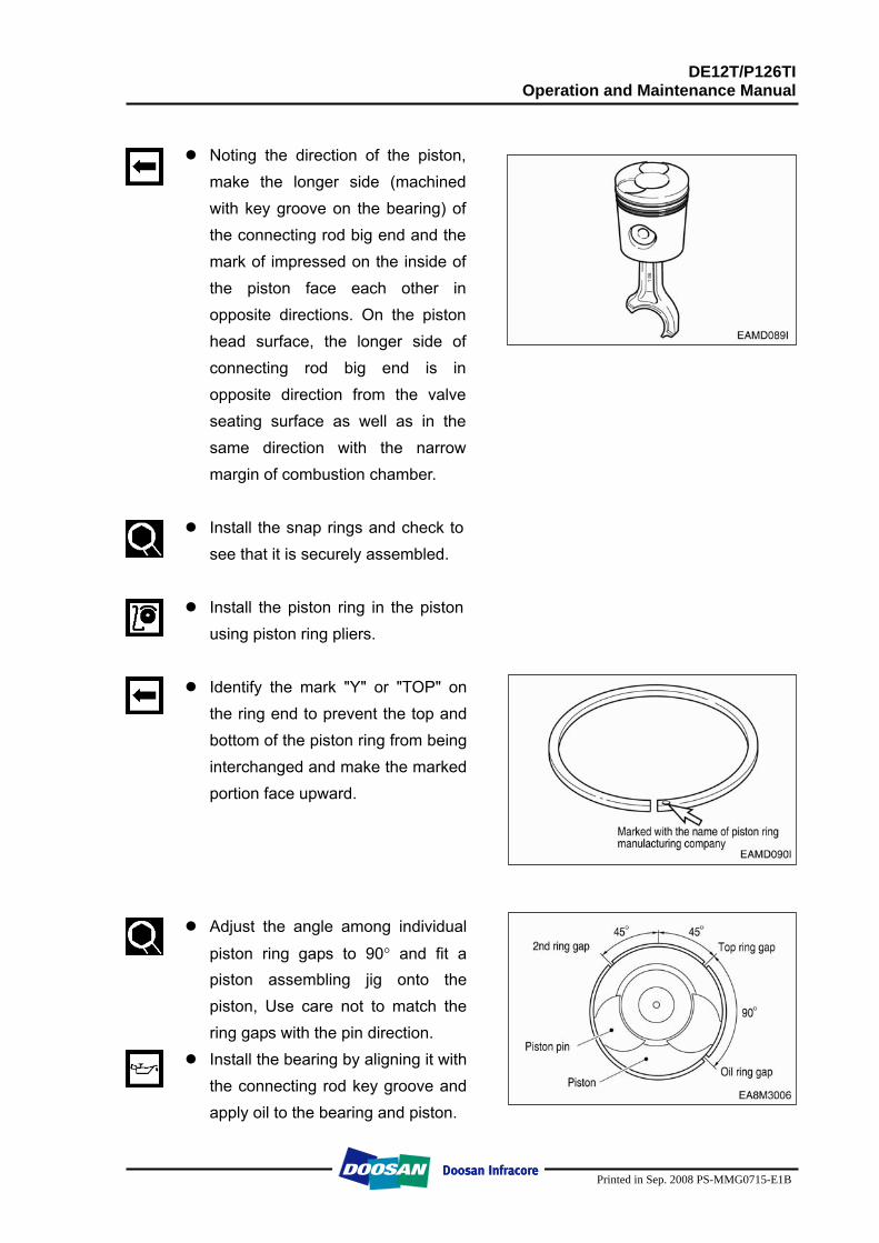
DE12T/P126TI Operation and Maintenance Manual
Printed in Sep. 2008 PS-MMG0715-E1B
Noting the direction of the piston,
make the longer side (machined with key groove on the bearing) of the connecting rod big end and the mark of impressed on the inside of the piston face each other in opposite directions. On the piston head surface, the longer side of connecting rod big end is in opposite direction from the valve seating surface as well as in the same direction with the narrow margin of combustion chamber.
Install the snap rings and check to
see that it is securely assembled.
Install the piston ring in the piston using piston ring pliers.
Identify the mark "Y" or "TOP" on
the ring end to prevent the top and bottom of the piston ring from being interchanged and make the marked portion face upward.
Adjust the angle among individual
piston ring gaps to 90° and fit a piston assembling jig onto the piston, Use care not to match the ring gaps with the pin direction.
Install the bearing by aligning it with the connecting rod key groove and apply oil to the bearing and piston.
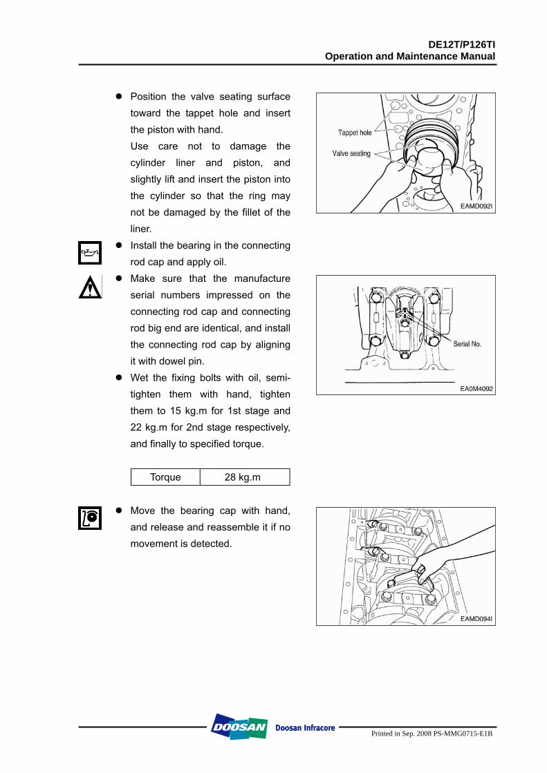
DE12T/P126TI Operation and Maintenance Manual
Printed in Sep. 2008 PS-MMG0715-E1B
Position the valve seating surface
toward the tappet hole and insert the piston with hand. Use care not to damage the cylinder liner and piston, and slightly lift and insert the piston into the cylinder so that the ring may not be damaged by the fillet of the liner.
Install the bearing in the connecting rod cap and apply oil.
Make sure that the manufacture serial numbers impressed on the connecting rod cap and connecting rod big end are identical, and install the connecting rod cap by aligning it with dowel pin.
Wet the fixing bolts with oil, semi-tighten them with hand, tighten them to 15 kg.m for 1st stage and 22 kg.m for 2nd stage respectively, and finally to specified torque.
Torque 28 kg.m
Move the bearing cap with hand,
and release and reassemble it if no movement is detected.
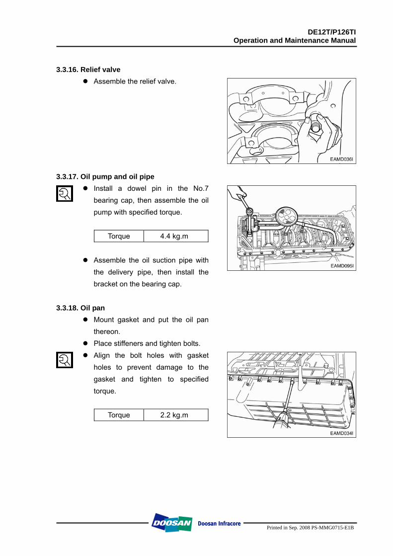
DE12T/P126TI Operation and Maintenance Manual
Printed in Sep. 2008 PS-MMG0715-E1B
3.3.16. Relief valve
Assemble the relief valve.
3.3.17. Oil pump and oil pipe Install a dowel pin in the No.7
bearing cap, then assemble the oil pump with specified torque.
Torque 4.4 kg.m
Assemble the oil suction pipe with
the delivery pipe, then install the bracket on the bearing cap.
3.3.18. Oil pan
Mount gasket and put the oil pan thereon.
Place stiffeners and tighten bolts. Align the bolt holes with gasket
holes to prevent damage to the gasket and tighten to specified torque.
Torque 2.2 kg.m
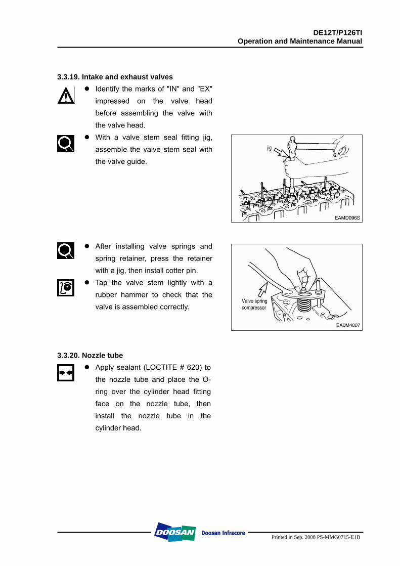
DE12T/P126TI Operation and Maintenance Manual
Printed in Sep. 2008 PS-MMG0715-E1B
3.3.19. Intake and exhaust valves Identify the marks of "IN" and "EX"
impressed on the valve head before assembling the valve with the valve head.
With a valve stem seal fitting jig, assemble the valve stem seal with the valve guide.
After installing valve springs and spring retainer, press the retainer with a jig, then install cotter pin.
Tap the valve stem lightly with a rubber hammer to check that the valve is assembled correctly.
3.3.20. Nozzle tube Apply sealant (LOCTITE # 620) to
the nozzle tube and place the O-ring over the cylinder head fitting face on the nozzle tube, then install the nozzle tube in the cylinder head.
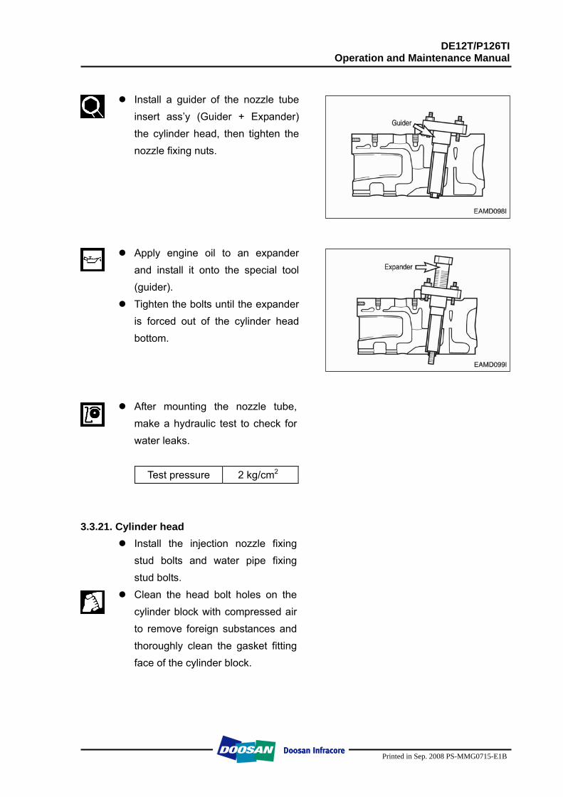
DE12T/P126TI Operation and Maintenance Manual
Printed in Sep. 2008 PS-MMG0715-E1B
Install a guider of the nozzle tube
insert ass’y (Guider + Expander) the cylinder head, then tighten the nozzle fixing nuts.
Apply engine oil to an expander
and install it onto the special tool (guider).
Tighten the bolts until the expander is forced out of the cylinder head bottom.
After mounting the nozzle tube, make a hydraulic test to check for water leaks.
Test pressure 2 kg/cm2
3.3.21. Cylinder head
Install the injection nozzle fixing stud bolts and water pipe fixing stud bolts.
Clean the head bolt holes on the cylinder block with compressed air to remove foreign substances and thoroughly clean the gasket fitting face of the cylinder block.
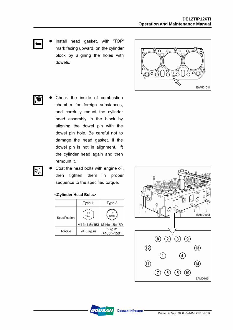
DE12T/P126TI Operation and Maintenance Manual
Printed in Sep. 2008 PS-MMG0715-E1B
Install head gasket, with 'TOP'
mark facing upward, on the cylinder block by aligning the holes with dowels.
Check the inside of combustion chamber for foreign substances, and carefully mount the cylinder head assembly in the block by aligning the dowel pin with the dowel pin hole. Be careful not to damage the head gasket. If the dowel pin is not in alignment, lift the cylinder head again and then remount it.
Coat the head bolts with engine oil, then tighten them in proper sequence to the specified torque.
<Cylinder Head Bolts>
Type 1 Type 2
Specification M14×1.5×153
M14×1.5×150
Torque 24.5 kg.m 6 kg.m +180°+150°
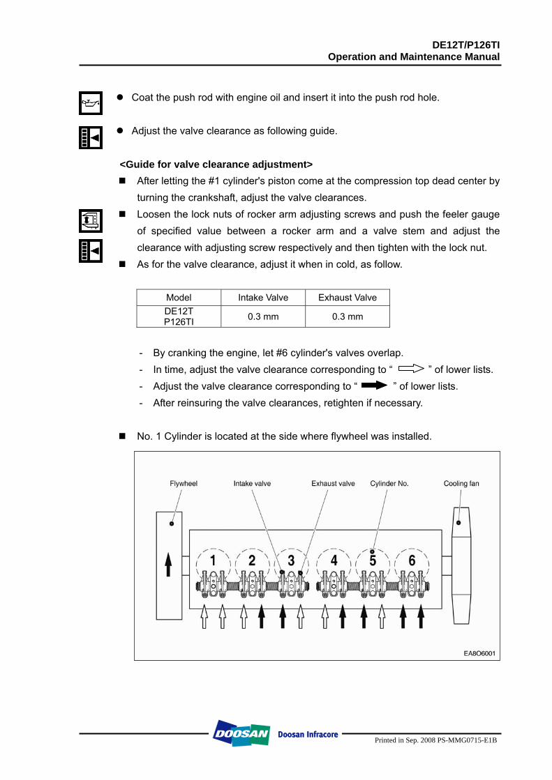
DE12T/P126TI Operation and Maintenance Manual
Printed in Sep. 2008 PS-MMG0715-E1B
Coat the push rod with engine oil and insert it into the push rod hole.
Adjust the valve clearance as following guide.
<Guide for valve clearance adjustment>
After letting the #1 cylinder's piston come at the compression top dead center by turning the crankshaft, adjust the valve clearances.
Loosen the lock nuts of rocker arm adjusting screws and push the feeler gauge of specified value between a rocker arm and a valve stem and adjust the clearance with adjusting screw respectively and then tighten with the lock nut.
As for the valve clearance, adjust it when in cold, as follow.
Model Intake Valve Exhaust Valve DE12T P126TI 0.3 mm 0.3 mm
- By cranking the engine, let #6 cylinder's valves overlap. - In time, adjust the valve clearance corresponding to “ ” of lower lists. - Adjust the valve clearance corresponding to “ ” of lower lists. - After reinsuring the valve clearances, retighten if necessary.
No. 1 Cylinder is located at the side where flywheel was installed.
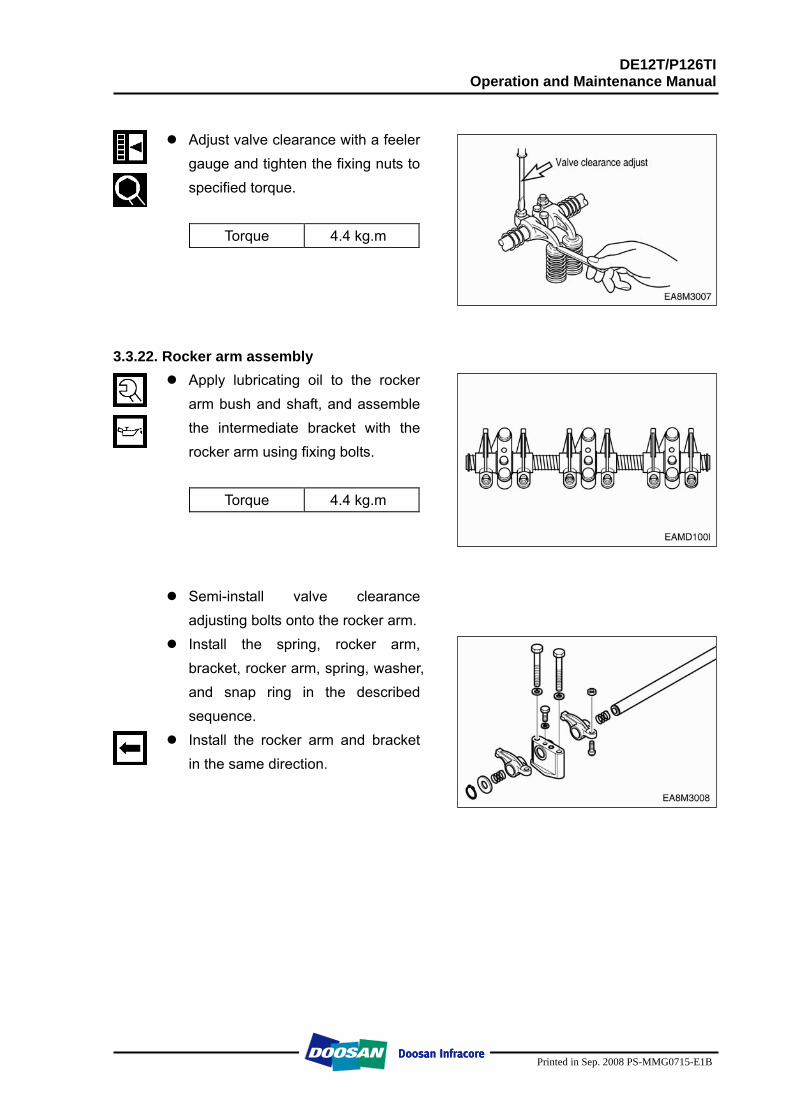
DE12T/P126TI Operation and Maintenance Manual
Printed in Sep. 2008 PS-MMG0715-E1B
Adjust valve clearance with a feeler
gauge and tighten the fixing nuts to specified torque.
Torque 4.4 kg.m
3.3.22. Rocker arm assembly
Apply lubricating oil to the rocker arm bush and shaft, and assemble the intermediate bracket with the rocker arm using fixing bolts.
Torque 4.4 kg.m
Semi-install valve clearance adjusting bolts onto the rocker arm.
Install the spring, rocker arm, bracket, rocker arm, spring, washer, and snap ring in the described sequence.
Install the rocker arm and bracket in the same direction.
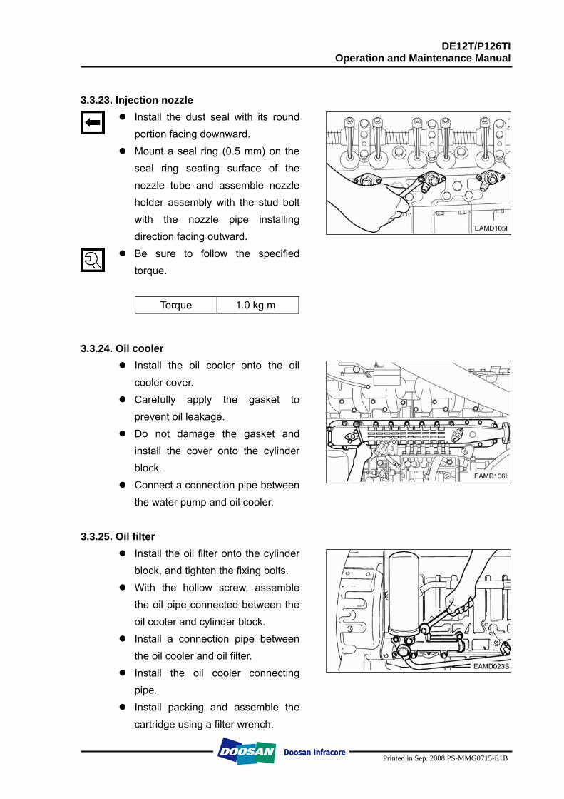
DE12T/P126TI Operation and Maintenance Manual
Printed in Sep. 2008 PS-MMG0715-E1B
3.3.23. Injection nozzle
Install the dust seal with its round portion facing downward.
Mount a seal ring (0.5 mm) on the seal ring seating surface of the nozzle tube and assemble nozzle holder assembly with the stud bolt with the nozzle pipe installing direction facing outward.
Be sure to follow the specified torque.
Torque 1.0 kg.m
3.3.24. Oil cooler Install the oil cooler onto the oil
cooler cover. Carefully apply the gasket to
prevent oil leakage. Do not damage the gasket and
install the cover onto the cylinder block.
Connect a connection pipe between the water pump and oil cooler.
3.3.25. Oil filter
Install the oil filter onto the cylinder block, and tighten the fixing bolts.
With the hollow screw, assemble the oil pipe connected between the oil cooler and cylinder block.
Install a connection pipe between the oil cooler and oil filter.
Install the oil cooler connecting pipe.
Install packing and assemble the cartridge using a filter wrench.
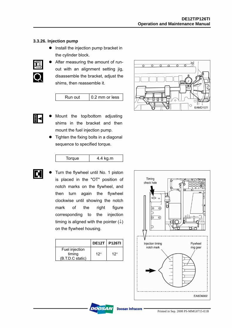
DE12T/P126TI Operation and Maintenance Manual
Printed in Sep. 2008 PS-MMG0715-E1B
3.3.26. Injection pump
Install the injection pump bracket in the cylinder block.
After measuring the amount of run-out with an alignment setting jig, disassemble the bracket, adjust the shims, then reassemble it.
Run out 0.2 mm or less
Mount the top/bottom adjusting shims in the bracket and then mount the fuel injection pump.
Tighten the fixing bolts in a diagonal sequence to specified torque.
Torque 4.4 kg.m
Turn the flywheel until No. 1 piston
is placed in the "OT" position of notch marks on the flywheel, and then turn again the flywheel clockwise until showing the notch mark of the right figure corresponding to the injection
timing is aligned with the pointer (↓) on the flywheel housing.
DE12T P126TIFuel injection
timing (B.T.D.C static)
12° 12°
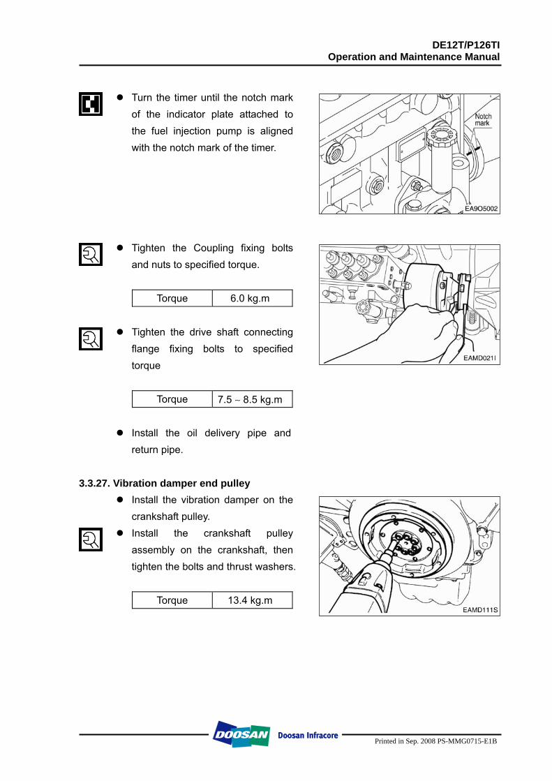
DE12T/P126TI Operation and Maintenance Manual
Printed in Sep. 2008 PS-MMG0715-E1B
Turn the timer until the notch mark
of the indicator plate attached to the fuel injection pump is aligned with the notch mark of the timer.
Tighten the Coupling fixing bolts and nuts to specified torque.
Torque 6.0 kg.m
Tighten the drive shaft connecting
flange fixing bolts to specified torque
Torque 7.5 ∼ 8.5 kg.m
Install the oil delivery pipe and return pipe.
3.3.27. Vibration damper end pulley
Install the vibration damper on the crankshaft pulley.
Install the crankshaft pulley assembly on the crankshaft, then tighten the bolts and thrust washers.
Torque 13.4 kg.m
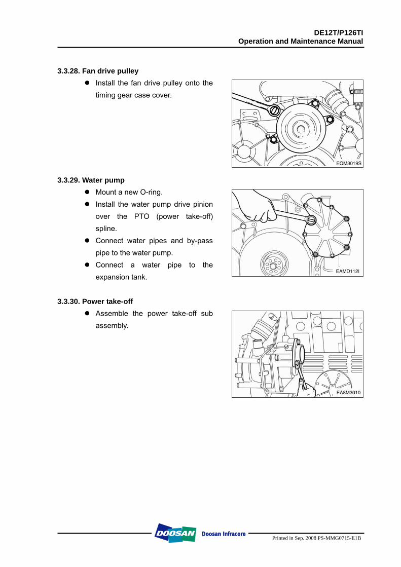
DE12T/P126TI Operation and Maintenance Manual
Printed in Sep. 2008 PS-MMG0715-E1B
3.3.28. Fan drive pulley
Install the fan drive pulley onto the timing gear case cover.
3.3.29. Water pump
Mount a new O-ring. Install the water pump drive pinion
over the PTO (power take-off) spline.
Connect water pipes and by-pass pipe to the water pump.
Connect a water pipe to the expansion tank.
3.3.30. Power take-off
Assemble the power take-off sub assembly.
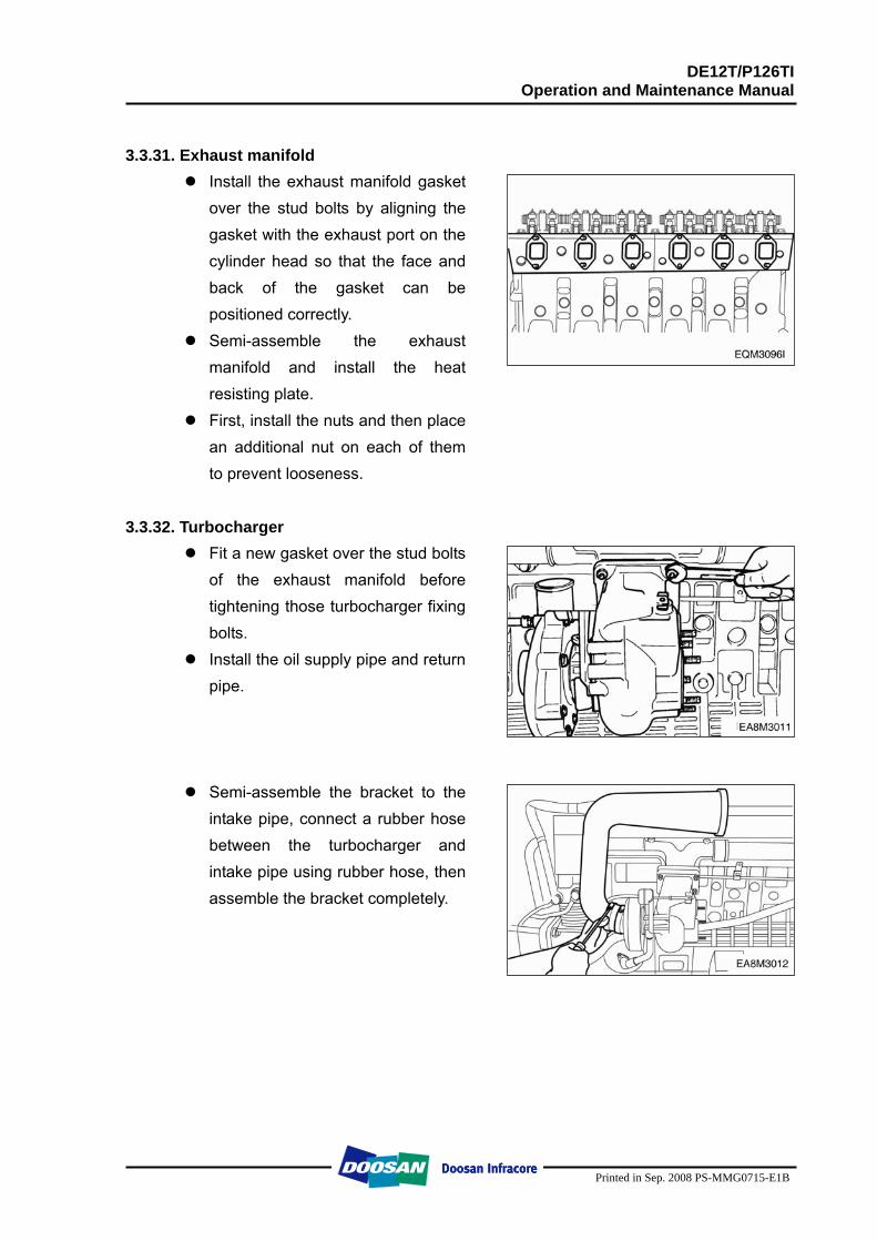
DE12T/P126TI Operation and Maintenance Manual
Printed in Sep. 2008 PS-MMG0715-E1B
3.3.31. Exhaust manifold
Install the exhaust manifold gasket over the stud bolts by aligning the gasket with the exhaust port on the cylinder head so that the face and back of the gasket can be positioned correctly.
Semi-assemble the exhaust manifold and install the heat resisting plate.
First, install the nuts and then place an additional nut on each of them to prevent looseness.
3.3.32. Turbocharger
Fit a new gasket over the stud bolts of the exhaust manifold before tightening those turbocharger fixing bolts.
Install the oil supply pipe and return pipe.
Semi-assemble the bracket to the intake pipe, connect a rubber hose between the turbocharger and intake pipe using rubber hose, then assemble the bracket completely.
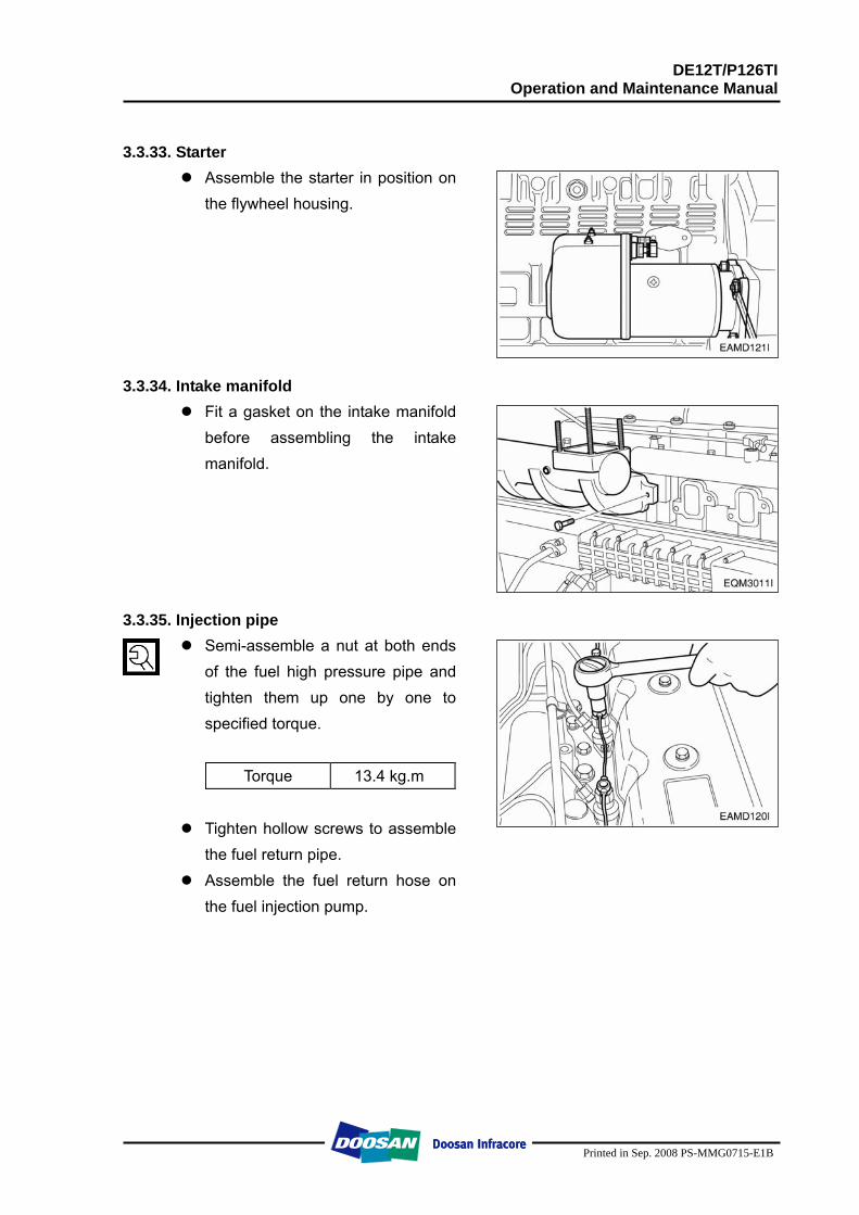
DE12T/P126TI Operation and Maintenance Manual
Printed in Sep. 2008 PS-MMG0715-E1B
3.3.33. Starter
Assemble the starter in position on the flywheel housing.
3.3.34. Intake manifold
Fit a gasket on the intake manifold before assembling the intake manifold.
3.3.35. Injection pipe
Semi-assemble a nut at both ends of the fuel high pressure pipe and tighten them up one by one to specified torque.
Torque 13.4 kg.m
Tighten hollow screws to assemble
the fuel return pipe. Assemble the fuel return hose on
the fuel injection pump.
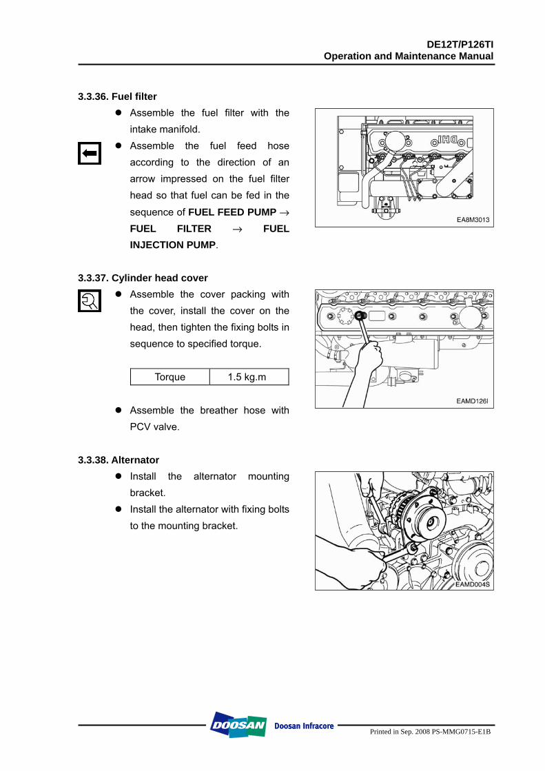
DE12T/P126TI Operation and Maintenance Manual
Printed in Sep. 2008 PS-MMG0715-E1B
3.3.36. Fuel filter
Assemble the fuel filter with the intake manifold.
Assemble the fuel feed hose according to the direction of an arrow impressed on the fuel filter head so that fuel can be fed in the
sequence of FUEL FEED PUMP → FUEL FILTER → FUEL INJECTION PUMP.
3.3.37. Cylinder head cover
Assemble the cover packing with the cover, install the cover on the head, then tighten the fixing bolts in sequence to specified torque.
Torque 1.5 kg.m
Assemble the breather hose with
PCV valve. 3.3.38. Alternator
Install the alternator mounting bracket.
Install the alternator with fixing bolts to the mounting bracket.
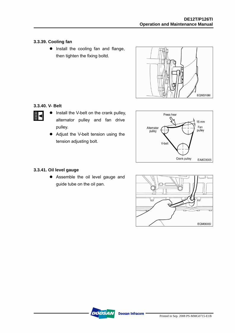
DE12T/P126TI Operation and Maintenance Manual
Printed in Sep. 2008 PS-MMG0715-E1B
3.3.39. Cooling fan
Install the cooling fan and flange, then tighten the fixing boltd.
3.3.40. V- Belt
Install the V-belt on the crank pulley, alternator pulley and fan drive pulley.
Adjust the V-belt tension using the tension adjusting bolt.
3.3.41. Oil level gauge
Assemble the oil level gauge and guide tube on the oil pan.
DE12T/P126TI Operation and Maintenance Manual
Printed in Sep. 2008 PS-MMG0715-E1B
4. Commissioning and Operation 4.1. Preparation
At the time of initial commissioning of a new or overhauled engine make sure to have observed the "Technical Information for the installation DOOSAN generator engines".
Oil filler neck on cylinder head cover
Before daily starting of the engine, check the fuel, coolant and oil level, replenish if necessary. The notches in the dipstick indicate the highest and lowest permissible oil levels The oil required in the sump is specified in the "Engine Specification”.
NOTE: The oil required to fill the oil fillers and pipes depends upon the engine and use and must be determined individually at the time of initial commissioning. (Make the Max and Min. marks of the determined quantity on the oil level gauge.)
Cleanliness
Ensure outmost cleanliness when handling fuels, lubricants and coolants.
4.2. Breaking-in 4.2.1. Operation of a new engine (Break-In)
Because the sliding surfaces of a new engine are not lapped enough, the oil film can be destroyed easily by overload or overspeed and the engine life-time may be shortened. Therefore the following things must be obeyed by all means.
Up to the first 2,000 km (150 hours)
Engine should be run at fast idling until the temperature of the engine becomes normal operating condition.
Overload or continuous high speed operation should be avoided. High speed operation with no load should be prevented. Abrupt start and stop of the engine should be avoided. Engine speed must be under 70% of its maximum speed. Maintenance and inspection must be accomplished thoroughly.
DE12T/P126TI Operation and Maintenance Manual
Printed in Sep. 2008 PS-MMG0715-E1B
4.2.2. Check points for break-in
During the break-in (the initial running of the engine) period, be particularly observant as follows: 1) Check engine oil level frequently. Maintain oil level in the safe range, between
the "min." and “max." marks on dipstick.
NOTE: If you have a problem getting a good oil level reading on dipstick, rotate dipstick 180° and re-insert for check.
2) Watch the oil pressure warning lamp. If the lamp blinks, it may be the oil pick-up
screen is not covered with oil. Check oil dipstick. Add oil to the oil pan, if required. Do not overfill. If level is correct and the status still exists, see your DEALER for possible switch or oil pump and line malfunction.
NOTE: Oil pressure will rise as RPM increases, and fall as RPM decreases. In addition, cold oil will generally show higher oil pressure for any specific RPM than hot oil. Both of these conditions reflect normal engine operation.
3) Watch the engine water temperature gauge and be sure there is proper water
circulation. The water temperature gauge needle will fluctuate if water level in expansion tank is too low. At the end of the break-in period, remove break-in oil and replace the oil filter. Fill oil pan with recommended engine oil. Refer to following table.
<Engine oil capacity>
Oil pan (only)
DE12T 23 liter P126TI 23 liter
4.2.3. Operating after break-In When starting a cold engine, always allow the engine to warm up gradually. Never run the engine at full throttle until the engine is thoroughly warmed up. Be sure to check the oil level frequently during the first 50 hours of operation, since the oil consumption will be high until the piston rings are properly seated.
DE12T/P126TI Operation and Maintenance Manual
Printed in Sep. 2008 PS-MMG0715-E1B
4.3. Inspections after Starting
During operation the oil pressure in the engine lubrication system must be monitored. If the monitoring devices register a drop in the lube oil pressure, switch off the engine immediately. And the charge warning lamp of the alternator should go out when the engine is running.
Do not disconnect the battery or pole terminals or the cables! If, during operation, the battery charge lamp suddenly lights up, stop the engine
immediately and remedy the fault in the electrical system! Engine should be stopped if the color, the noise or the odor of exhaust gas is not
normal. Confirm the following things through warning lamps and gauge panel.
4.3.1. Pressure of lubricating oil
The normal pressure comes up to 1 kg/cm2 (1.0 bar) at idling and 3 ~ 5 kg/cm2 (3.0 ~ 4.9 bar) at maximum speed. If the pressure fluctuates at idling or does not reach up to the expected level at high speed, shut down the engine immediately and check the oil level and the oil line leakage.
4.3.2. Temperature of cooling water
The cooling water temperature should be 78 ~ 85 °C in normal operating conditions. Abnormally high cooling water temperature could cause the overheating of engine and the sticking of cylinder components. And excessively low cooling water temperature increases the fuel consumption, accelerates the wears of cylinder liners and shortens the engine life-time.
DE12T/P126TI Operation and Maintenance Manual
Printed in Sep. 2008 PS-MMG0715-E1B
4.4. Operation in Winter Time
Pay special attention to the freezing of cooling water and the viscosity of lubricating oil.
4.4.1. Prevention against the freeze of cooling water
When not using anti-freeze, completely discharge the whole cooling water after engine running. The freeze of cooling water causes the fatal damages of the engine. Because the anti-freeze is used to prevent cooling water from freeze, consult "The amount of anti-freeze".
4.4.2. Prevention against excessive cooling
Drop of thermal efficiency caused by excessive cooling increases fuel consumption, therefore prevent the engine from excessive cooling. If the temperature of coolant
does not reach to normal condition (78 ~ 85 °C) after continuous operation, examine the thermostat or the other cooling lines.
4.4.3. Lubricating oil
As cold weather leads to the rise of oil viscosity, engine speed becomes unstable after starting. Therefore the lubricating oil for winter should be used to prevent this unstability. Refer to “Lubricating System section”.
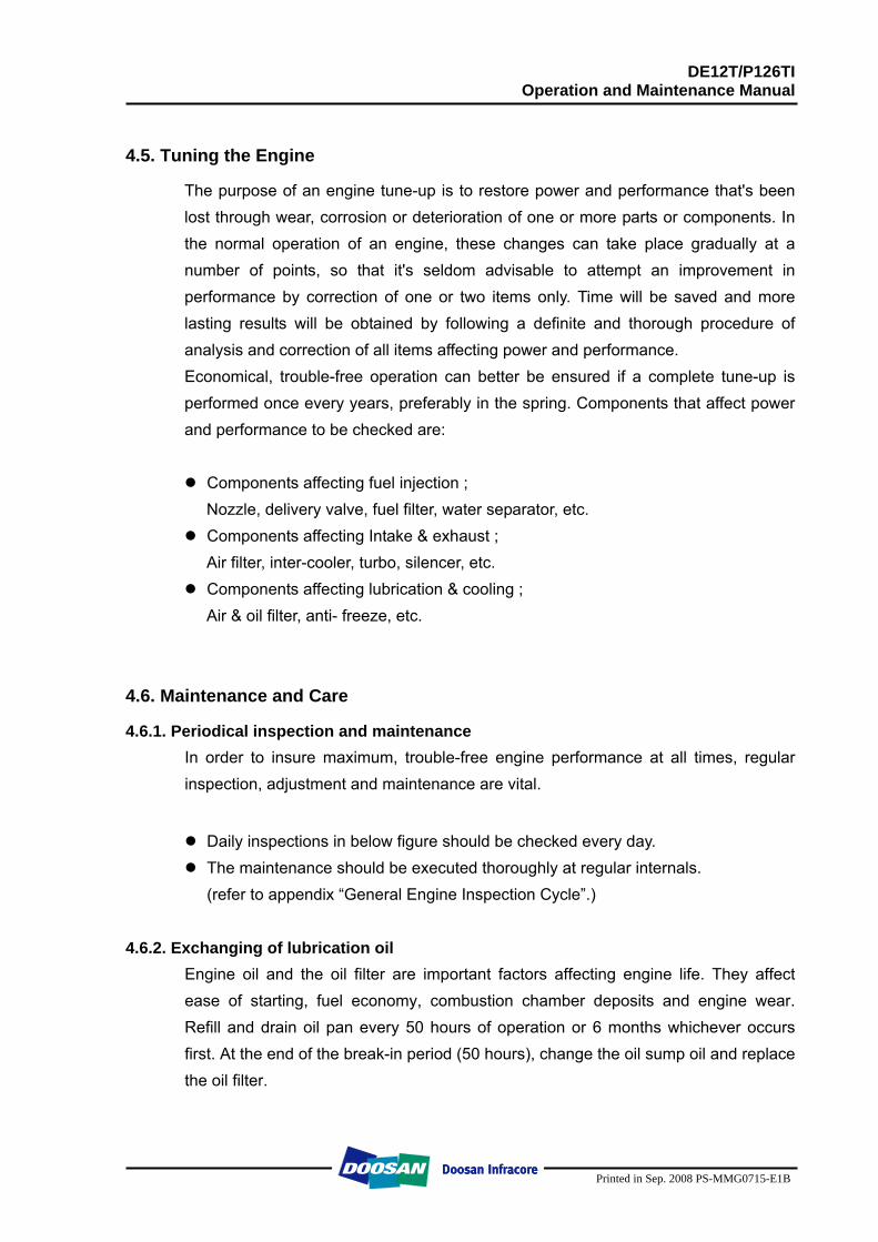
DE12T/P126TI Operation and Maintenance Manual
Printed in Sep. 2008 PS-MMG0715-E1B
4.5. Tuning the Engine
The purpose of an engine tune-up is to restore power and performance that's been lost through wear, corrosion or deterioration of one or more parts or components. In the normal operation of an engine, these changes can take place gradually at a number of points, so that it's seldom advisable to attempt an improvement in performance by correction of one or two items only. Time will be saved and more lasting results will be obtained by following a definite and thorough procedure of analysis and correction of all items affecting power and performance. Economical, trouble-free operation can better be ensured if a complete tune-up is performed once every years, preferably in the spring. Components that affect power and performance to be checked are:
Components affecting fuel injection ;
Nozzle, delivery valve, fuel filter, water separator, etc. Components affecting Intake & exhaust ;
Air filter, inter-cooler, turbo, silencer, etc. Components affecting lubrication & cooling ;
Air & oil filter, anti- freeze, etc.
4.6. Maintenance and Care
4.6.1. Periodical inspection and maintenance In order to insure maximum, trouble-free engine performance at all times, regular inspection, adjustment and maintenance are vital.
Daily inspections in below figure should be checked every day. The maintenance should be executed thoroughly at regular internals.
(refer to appendix “General Engine Inspection Cycle”.)
4.6.2. Exchanging of lubrication oil
Engine oil and the oil filter are important factors affecting engine life. They affect ease of starting, fuel economy, combustion chamber deposits and engine wear. Refill and drain oil pan every 50 hours of operation or 6 months whichever occurs first. At the end of the break-in period (50 hours), change the oil sump oil and replace the oil filter.
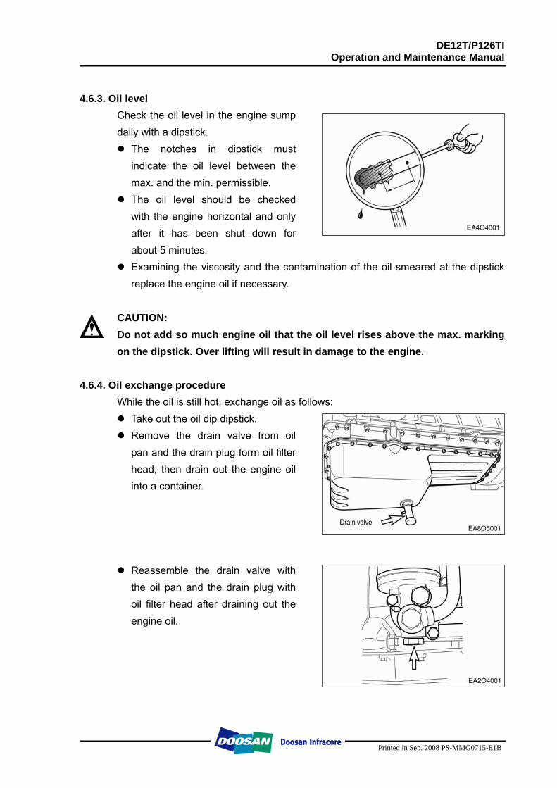
DE12T/P126TI Operation and Maintenance Manual
Printed in Sep. 2008 PS-MMG0715-E1B
4.6.3. Oil level
Check the oil level in the engine sump daily with a dipstick.
The notches in dipstick must indicate the oil level between the max. and the min. permissible.
The oil level should be checked with the engine horizontal and only after it has been shut down for about 5 minutes.
Examining the viscosity and the contamination of the oil smeared at the dipstick replace the engine oil if necessary.
CAUTION: Do not add so much engine oil that the oil level rises above the max. marking on the dipstick. Over lifting will result in damage to the engine.
4.6.4. Oil exchange procedure
While the oil is still hot, exchange oil as follows: Take out the oil dip dipstick. Remove the drain valve from oil
pan and the drain plug form oil filter head, then drain out the engine oil into a container.
Reassemble the drain valve with the oil pan and the drain plug with oil filter head after draining out the engine oil.
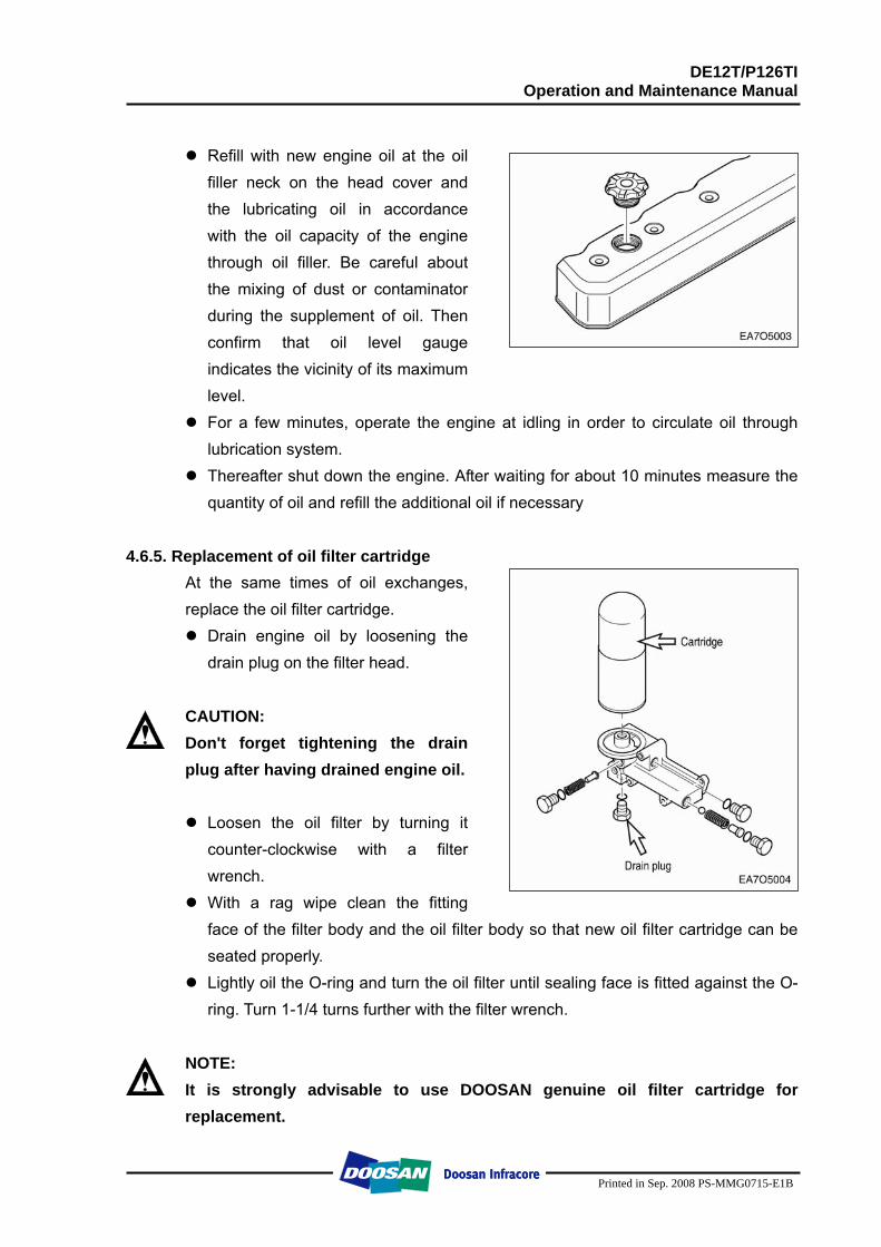
DE12T/P126TI Operation and Maintenance Manual
Printed in Sep. 2008 PS-MMG0715-E1B
Refill with new engine oil at the oil
filler neck on the head cover and the lubricating oil in accordance with the oil capacity of the engine through oil filler. Be careful about the mixing of dust or contaminator during the supplement of oil. Then confirm that oil level gauge indicates the vicinity of its maximum level.
For a few minutes, operate the engine at idling in order to circulate oil through lubrication system.
Thereafter shut down the engine. After waiting for about 10 minutes measure the quantity of oil and refill the additional oil if necessary
4.6.5. Replacement of oil filter cartridge
At the same times of oil exchanges, replace the oil filter cartridge.
Drain engine oil by loosening the drain plug on the filter head.
CAUTION: Don't forget tightening the drain plug after having drained engine oil.
Loosen the oil filter by turning it
counter-clockwise with a filter wrench.
With a rag wipe clean the fitting face of the filter body and the oil filter body so that new oil filter cartridge can be seated properly.
Lightly oil the O-ring and turn the oil filter until sealing face is fitted against the O-ring. Turn 1-1/4 turns further with the filter wrench.
NOTE: It is strongly advisable to use DOOSAN genuine oil filter cartridge for replacement.
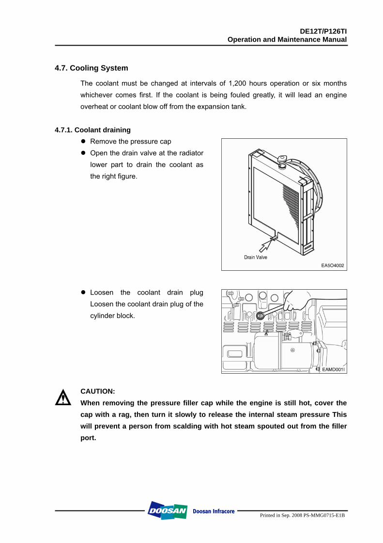
DE12T/P126TI Operation and Maintenance Manual
Printed in Sep. 2008 PS-MMG0715-E1B
4.7. Cooling System
The coolant must be changed at intervals of 1,200 hours operation or six months whichever comes first. If the coolant is being fouled greatly, it will lead an engine overheat or coolant blow off from the expansion tank.
4.7.1. Coolant draining
Remove the pressure cap Open the drain valve at the radiator
lower part to drain the coolant as the right figure.
Loosen the coolant drain plug Loosen the coolant drain plug of the cylinder block.
CAUTION: When removing the pressure filler cap while the engine is still hot, cover the cap with a rag, then turn it slowly to release the internal steam pressure This will prevent a person from scalding with hot steam spouted out from the filler port.
DE12T/P126TI Operation and Maintenance Manual
Printed in Sep. 2008 PS-MMG0715-E1B
4.7.2. Cleaning of the cooling inside system circuit
(by authorized specialist personnel) When the cooling system circuit are fouled with water scales or sludge particles, the cooling efficiency will be lowered. Investigations have shown that in many cases the poor condition of the coolant and /or the cooling system accounts for damage to the water pump mechanical seal, The poor condition of the cooling system is normally due to use of unsuitable or no anti-freezing agents and corrosion inhibitor or defect, not early enough replaced covers for filler neck and working valves. If twice in a short time the water pump of an engine develops leases or the coolant is heavily contaminated (dull, brown, mechanically contaminated, grey or black sings of a leakage on the water pump casing) clean the cooling system prior to removing that water pump as follows. a) Drain coolant. b) Remove thermostats, so that the whole cooling system is immediately flown
through when cleaned. c) Fill the cooling system with a mixture of potable water and 1.5% by volume of
cleaner. (Henkel P3T5175)
d) Warm up engine under load. After a temperature of 60°C is reached, run engine for a further 15 minutes.
e) Drain cleaning fluid. f) Repeat steps c) and d). g) Flush cooling system. h) Replace drain plug by drain plug with a bore of 8mm diameter. i) Fill cooling system with hot water. j) Run engine at idle for 30 minutes. At the same time continuously replenish the
water leaking from the bore in drain plug by adding fresh water.
Periodically clean the circuit interior with a cleaner. - Cooling system cleaning interval: Every 1,200 hours.
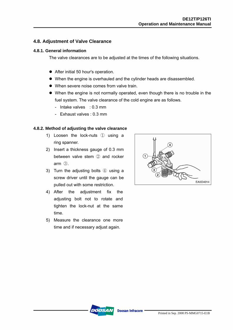
DE12T/P126TI Operation and Maintenance Manual
Printed in Sep. 2008 PS-MMG0715-E1B
4.8. Adjustment of Valve Clearance
4.8.1. General information The valve clearances are to be adjusted at the times of the following situations.
After initial 50 hour's operation. When the engine is overhauled and the cylinder heads are disassembled. When severe noise comes from valve train. When the engine is not normally operated, even though there is no trouble in the
fuel system. The valve clearance of the cold engine are as follows. - Intake valves : 0.3 mm - Exhaust valves : 0.3 mm
4.8.2. Method of adjusting the valve clearance
1) Loosen the lock-nuts ① using a ring spanner.
2) Insert a thickness gauge of 0.3 mm between valve stem ② and rocker arm ③.
3) Turn the adjusting bolts ④ using a screw driver until the gauge can be pulled out with some restriction.
4) After the adjustment fix the adjusting bolt not to rotate and tighten the lock-nut at the same time.
5) Measure the clearance one more time and if necessary adjust again.
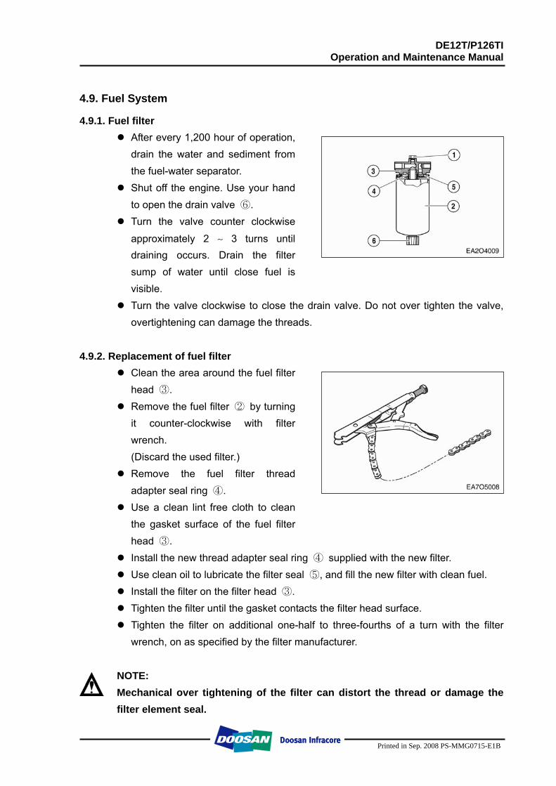
DE12T/P126TI Operation and Maintenance Manual
Printed in Sep. 2008 PS-MMG0715-E1B
4.9. Fuel System
4.9.1. Fuel filter After every 1,200 hour of operation,
drain the water and sediment from the fuel-water separator.
Shut off the engine. Use your hand to open the drain valve ⑥.
Turn the valve counter clockwise
approximately 2 ∼ 3 turns until draining occurs. Drain the filter sump of water until close fuel is visible.
Turn the valve clockwise to close the drain valve. Do not over tighten the valve, overtightening can damage the threads.
4.9.2. Replacement of fuel filter
Clean the area around the fuel filter head ③.
Remove the fuel filter ② by turning it counter-clockwise with filter wrench. (Discard the used filter.)
Remove the fuel filter thread adapter seal ring ④.
Use a clean lint free cloth to clean the gasket surface of the fuel filter head ③.
Install the new thread adapter seal ring ④ supplied with the new filter. Use clean oil to lubricate the filter seal ⑤, and fill the new filter with clean fuel. Install the filter on the filter head ③. Tighten the filter until the gasket contacts the filter head surface. Tighten the filter on additional one-half to three-fourths of a turn with the filter
wrench, on as specified by the filter manufacturer.
NOTE: Mechanical over tightening of the filter can distort the thread or damage the filter element seal.
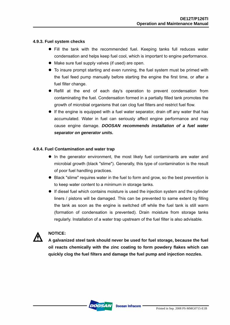
DE12T/P126TI Operation and Maintenance Manual
Printed in Sep. 2008 PS-MMG0715-E1B
4.9.3. Fuel system checks
Fill the tank with the recommended fuel. Keeping tanks full reduces water condensation and helps keep fuel cool, which is important to engine performance.
Make sure fuel supply valves (if used) are open. To insure prompt starting and even running, the fuel system must be primed with
the fuel feed pump manually before starting the engine the first time, or after a fuel filter change.
Refill at the end of each day's operation to prevent condensation from contaminating the fuel. Condensation formed in a partially filled tank promotes the growth of microbial organisms that can clog fuel filters and restrict fuel flow.
If the engine is equipped with a fuel water separator, drain off any water that has accumulated. Water in fuel can seriously affect engine performance and may cause engine damage. DOOSAN recommends installation of a fuel water separator on generator units.
4.9.4. Fuel Contamination and water trap
In the generator environment, the most likely fuel contaminants are water and microbial growth (black "slime"). Generally, this type of contamination is the result of poor fuel handling practices.
Black "slime" requires water in the fuel to form and grow, so the best prevention is to keep water content to a minimum in storage tanks.
If diesel fuel which contains moisture is used the injection system and the cylinder liners / pistons will be damaged. This can be prevented to same extent by filling the tank as soon as the engine is switched off while the fuel tank is still warm (formation of condensation is prevented). Drain moisture from storage tanks regularly. Installation of a water trap upstream of the fuel filter is also advisable.
NOTICE: A galvanized steel tank should never be used for fuel storage, because the fuel oil reacts chemically with the zinc coating to form powdery flakes which can quickly clog the fuel filters and damage the fuel pump and injection nozzles.
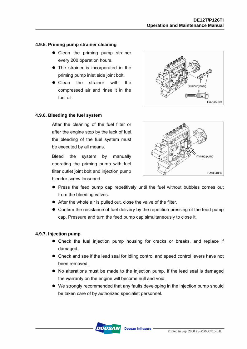
DE12T/P126TI Operation and Maintenance Manual
Printed in Sep. 2008 PS-MMG0715-E1B
4.9.5. Priming pump strainer cleaning
Clean the priming pump strainer every 200 operation hours.
The strainer is incorporated in the priming pump inlet side joint bolt.
Clean the strainer with the compressed air and rinse it in the fuel oil.
4.9.6. Bleeding the fuel system
After the cleaning of the fuel filter or after the engine stop by the lack of fuel, the bleeding of the fuel system must be executed by all means.
Bleed the system by manually operating the priming pump with fuel filter outlet joint bolt and injection pump bleeder screw loosened.
Press the feed pump cap repetitively until the fuel without bubbles comes out from the bleeding valves.
After the whole air is pulled out, close the valve of the filter. Confirm the resistance of fuel delivery by the repetition pressing of the feed pump
cap, Pressure and turn the feed pump cap simultaneously to close it.
4.9.7. Injection pump Check the fuel injection pump housing for cracks or breaks, and replace if
damaged. Check and see if the lead seal for idling control and speed control levers have not
been removed. No alterations must be made to the injection pump. If the lead seal is damaged
the warranty on the engine will become null and void. We strongly recommended that any faults developing in the injection pump should
be taken care of by authorized specialist personnel.
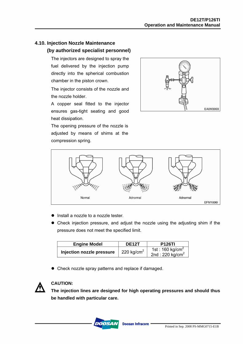
DE12T/P126TI Operation and Maintenance Manual
Printed in Sep. 2008 PS-MMG0715-E1B
4.10. Injection Nozzle Maintenance (by authorized specialist personnel)
The injectors are designed to spray the fuel delivered by the injection pump directly into the spherical combustion chamber in the piston crown.
The injector consists of the nozzle and the nozzle holder. A copper seal fitted to the injector ensures gas-tight seating and good heat dissipation. The opening pressure of the nozzle is adjusted by means of shims at the compression spring.
Install a nozzle to a nozzle tester. Check injection pressure, and adjust the nozzle using the adjusting shim if the
pressure does not meet the specified limit.
Engine Model DE12T P126TI
Injection nozzle pressure 220 kg/cm2 1st : 160 kg/cm2
2nd : 220 kg/cm2
Check nozzle spray patterns and replace if damaged.
CAUTION: The injection lines are designed for high operating pressures and should thus be handled with particular care.
DE12T/P126TI Operation and Maintenance Manual
Printed in Sep. 2008 PS-MMG0715-E1B
When mounting the pipes to the engine take care of good fitness. Do not bend pipes to permanent deformation (not for replacing the nozzles either). Do not mount any heavily bent pipes. Avoid bending the pipes at the ends by more than 2 to 3 degrees.
In case of faults in the injection system which might have resulted in excessive operating pressures, not only the failed part but also the injection line has to be replaced.
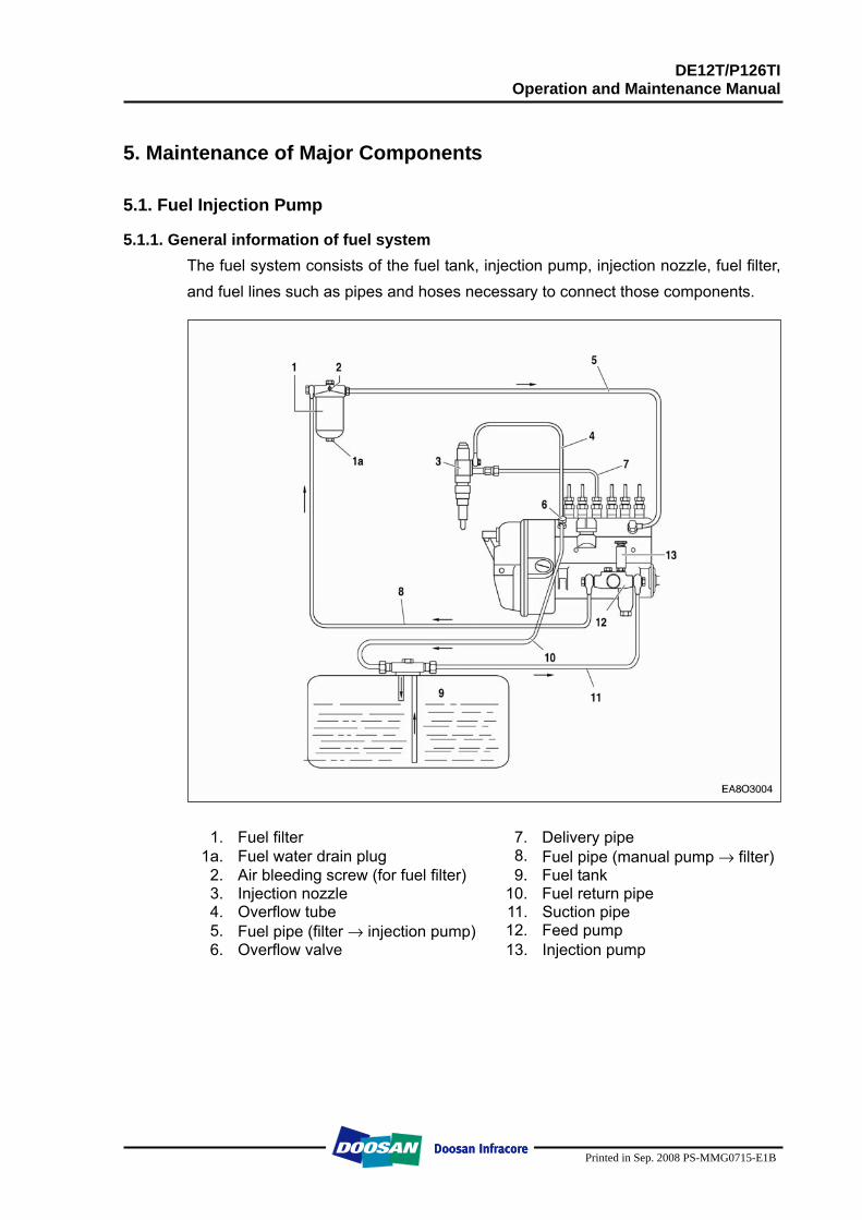
DE12T/P126TI Operation and Maintenance Manual
Printed in Sep. 2008 PS-MMG0715-E1B
5. Maintenance of Major Components 5.1. Fuel Injection Pump
5.1.1. General information of fuel system The fuel system consists of the fuel tank, injection pump, injection nozzle, fuel filter, and fuel lines such as pipes and hoses necessary to connect those components.
1. Fuel filter 7. Delivery pipe
1a. Fuel water drain plug 8. Fuel pipe (manual pump → filter) 2. Air bleeding screw (for fuel filter) 9. Fuel tank 3. Injection nozzle 10. Fuel return pipe 4. Overflow tube 11. Suction pipe 5. Fuel pipe (filter → injection pump) 12. Feed pump 6. Overflow valve 13. Injection pump
DE12T/P126TI Operation and Maintenance Manual
Printed in Sep. 2008 PS-MMG0715-E1B
5.1.2. Injection pump
The components relating to the injection pump should be serviced at regular intervals as the plunger and delivery valve may be worn after a given length of time for use and cause the deterioration of the engine. Make sure that servicing should be performed at the professional maintenance shop as authorized by Bosch or Zexel Company. For adjustment of fuel injection volume, refer to the 'Specifications of fuel injection pump' described on the following pages.
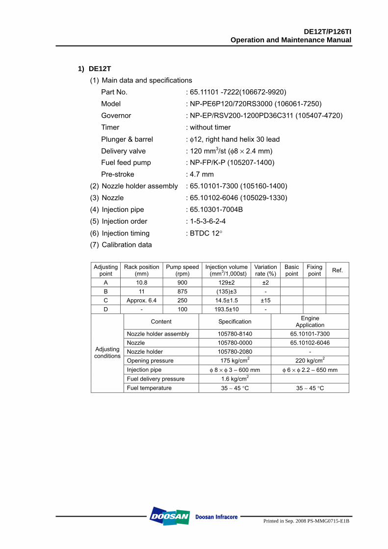
DE12T/P126TI Operation and Maintenance Manual
Printed in Sep. 2008 PS-MMG0715-E1B
1) DE12T
(1) Main data and specifications Part No. : 65.11101 -7222(106672-9920) Model : NP-PE6P120/720RS3000 (106061-7250) Governor : NP-EP/RSV200-1200PD36C311 (105407-4720) Timer : without timer
Plunger & barrel : φ12, right hand helix 30 lead Delivery valve : 120 mm3/st (φ8 × 2.4 mm) Fuel feed pump : NP-FP/K-P (105207-1400) Pre-stroke : 4.7 mm
(2) Nozzle holder assembly : 65.10101-7300 (105160-1400) (3) Nozzle : 65.10102-6046 (105029-1330) (4) Injection pipe : 65.10301-7004B (5) Injection order : 1-5-3-6-2-4
(6) Injection timing : BTDC 12° (7) Calibration data
Adjusting
point Rack position
(mm) Pump speed
(rpm) Injection volume
(mm3/1,000st) Variation rate (%)
Basic point
Fixing point Ref.
A 10.8 900 129±2 ±2 B 11 875 (135)±3 - C Approx. 6.4 250 14.5±1.5 ±15 D - 100 193.5±10 -
Content Specification Engine Application
Nozzle holder assembly 105780-8140 65.10101-7300 Nozzle 105780-0000 65.10102-6046 Nozzle holder 105780-2080 - Opening pressure 175 kg/cm2 220 kg/cm2 Injection pipe φ 8 × φ 3 – 600 mm φ 6 × φ 2.2 – 650 mm Fuel delivery pressure 1.6 kg/cm2
Adjusting conditions
Fuel temperature 35 ∼ 45 °C 35 ∼ 45 °C
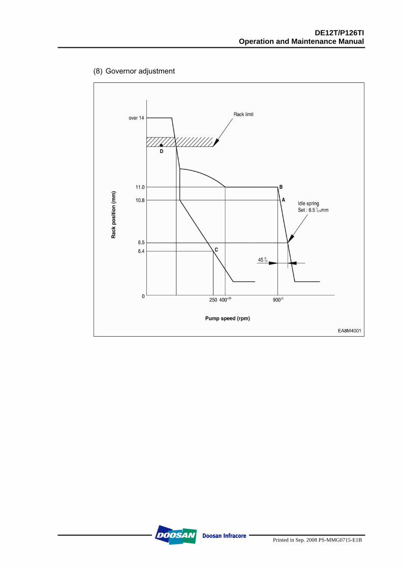
DE12T/P126TI Operation and Maintenance Manual
Printed in Sep. 2008 PS-MMG0715-E1B
(8) Governor adjustment
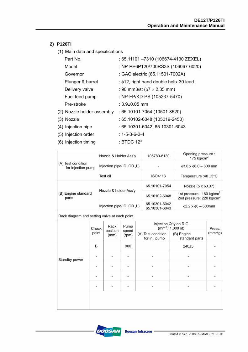
DE12T/P126TI Operation and Maintenance Manual
Printed in Sep. 2008 PS-MMG0715-E1B
2) P126TI
(1) Main data and specifications Part No. : 65.11101 –7310 (106674-4130 ZEXEL) Model : NP-PE6P120/700RS3S (106067-6020) Governor : GAC electric (65.11501-7002A)
Plunger & barrel : φ12, right hand double helix 30 lead Delivery valve : 90 mm3/st (φ7 × 2.35 mm) Fuel feed pump : NP-FP/KD-PS (105237-5470) Pre-stroke : 3.9±0.05 mm
(2) Nozzle holder assembly : 65.10101-7054 (10501-8520) (3) Nozzle : 65.10102-6048 (105019-2450) (4) Injection pipe : 65.10301-6042, 65.10301-6043 (5) Injection order : 1-5-3-6-2-4
(6) Injection timing : BTDC 12°
Nozzle & Holder Ass’y 105780-8130 Opening pressure : 175 kg/cm2
Injection pipe(ID ,OD ,L) - φ3.0 x φ8.0 – 600 mm (A) Test condition for injection pump
Test oil ISO4113 Temperature :40 ±5°C
65.10101-7054 Nozzle (5 x φ0.37) Nozzle & holder Ass’y
65.10102-6048 1st pressure : 160 kg/cm2 2nd pressure: 220 kg/cm2
(B) Engine standard parts
Injection pipe(ID, OD ,L) 65.10301-6042 65.10301-6043 φ2.2 x φ6 – 600mm
Rack diagram and setting valve at each point
Injection Q’ty on RIG (mm3 / 1,000 st) Check
point
Rack position (mm)
Pump speed (rpm) (A) Test condition
for inj. pump (B) Engine
standard parts
Press. (mmHg)
B 900 240±3 -
- - - - - -
- - - - - -
- - - - - -
- - - - - -
Standby power
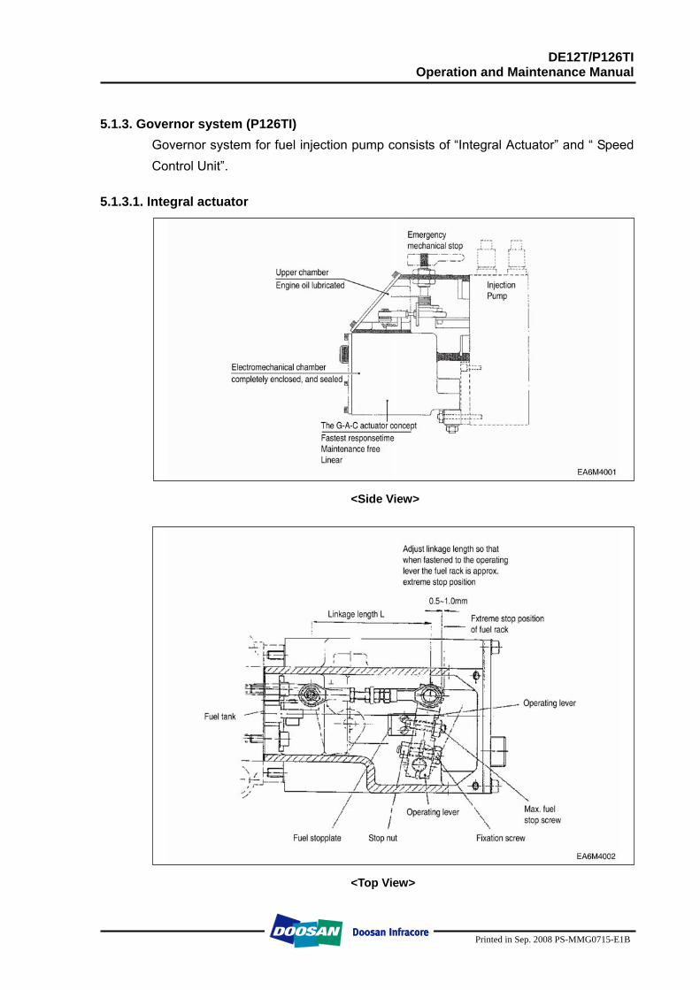
DE12T/P126TI Operation and Maintenance Manual
Printed in Sep. 2008 PS-MMG0715-E1B
5.1.3. Governor system (P126TI)
Governor system for fuel injection pump consists of “Integral Actuator” and “ Speed Control Unit”.
5.1.3.1. Integral actuator
<Side View>
<Top View>
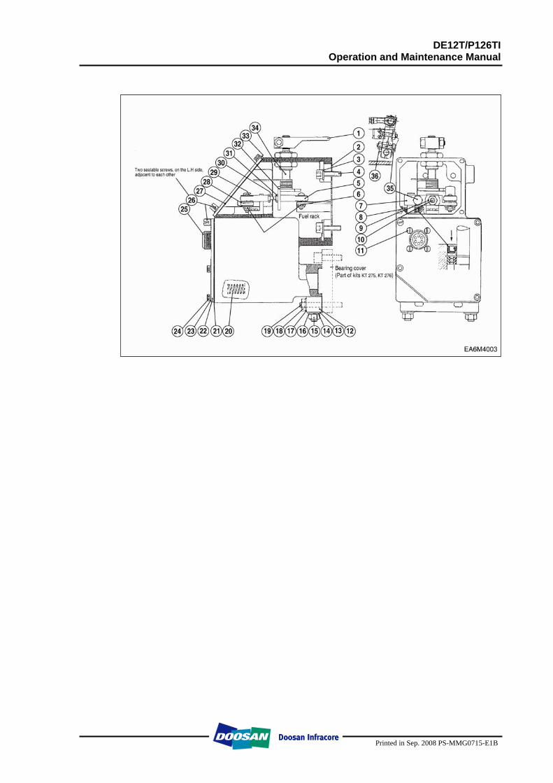
DE12T/P126TI Operation and Maintenance Manual
Printed in Sep. 2008 PS-MMG0715-E1B
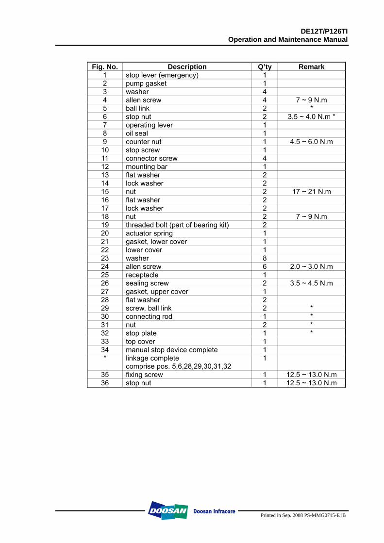
DE12T/P126TI Operation and Maintenance Manual
Printed in Sep. 2008 PS-MMG0715-E1B
Fig. No. Description Q’ty Remark
1 stop lever (emergency) 1 2 pump gasket 1 3 washer 4 4 allen screw 4 7 ~ 9 N.m 5 ball link 2 * 6 stop nut 2 3.5 ~ 4.0 N.m * 7 operating lever 1 8 oil seal 1 9 counter nut 1 4.5 ~ 6.0 N.m
10 stop screw 1 11 connector screw 4 12 mounting bar 1 13 flat washer 2 14 lock washer 2 15 nut 2 17 ~ 21 N.m 16 flat washer 2 17 lock washer 2 18 nut 2 7 ~ 9 N.m 19 threaded bolt (part of bearing kit) 2 20 actuator spring 1 21 gasket, lower cover 1 22 lower cover 1 23 washer 8 24 allen screw 6 2.0 ~ 3.0 N.m 25 receptacle 1 26 sealing screw 2 3.5 ~ 4.5 N.m 27 gasket, upper cover 1 28 flat washer 2 29 screw, ball link 2 * 30 connecting rod 1 * 31 nut 2 * 32 stop plate 1 * 33 top cover 1 34 manual stop device complete 1 * linkage complete
comprise pos. 5,6,28,29,30,31,32 1
35 fixing screw 1 12.5 ~ 13.0 N.m 36 stop nut 1 12.5 ~ 13.0 N.m
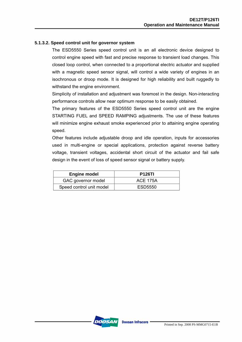
DE12T/P126TI Operation and Maintenance Manual
Printed in Sep. 2008 PS-MMG0715-E1B
5.1.3.2. Speed control unit for governor system
The ESD5550 Series speed control unit is an all electronic device designed to control engine speed with fast and precise response to transient load changes. This closed loop control, when connected to a proportional electric actuator and supplied with a magnetic speed sensor signal, will control a wide variety of engines in an isochronous or droop mode. It is designed for high reliability and built ruggedly to withstand the engine environment. Simplicity of installation and adjustment was foremost in the design. Non-interacting performance controls allow near optimum response to be easily obtained. The primary features of the ESD5550 Series speed control unit are the engine STARTING FUEL and SPEED RAMPING adjustments. The use of these features will minimize engine exhaust smoke experienced prior to attaining engine operating speed. Other features include adjustable droop and idle operation, inputs for accessories used in multi-engine or special applications, protection against reverse battery voltage, transient voltages, accidental short circuit of the actuator and fail safe design in the event of loss of speed sensor signal or battery supply.
Engine model P126TI
GAC governor model ACE 175A Speed control unit model ESD5550
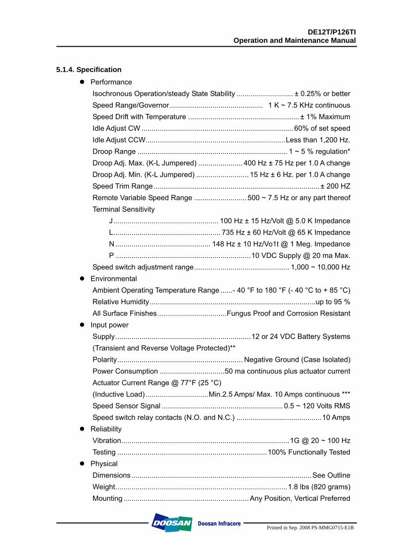
DE12T/P126TI Operation and Maintenance Manual
Printed in Sep. 2008 PS-MMG0715-E1B
5.1.4. Specification
Performance Isochronous Operation/steady State Stability ............................ ± 0.25% or better Speed Range/Governor .............................................. 1 K ~ 7.5 KHz continuous Speed Drift with Temperature ....................................................... ± 1% Maximum Idle Adjust CW ........................................................................... 60% of set speed Idle Adjust CCW.....................................................................Less than 1,200 Hz. Droop Range .......................................................................... 1 ~ 5 % regulation* Droop Adj. Max. (K-L Jumpered) ...................... 400 Hz ± 75 Hz per 1.0 A change Droop Adj. Min. (K-L Jumpered) .......................... 15 Hz ± 6 Hz. per 1.0 A change Speed Trim Range.................................................................................. ± 200 HZ Remote Variable Speed Range ..........................500 ~ 7.5 Hz or any part thereof Terminal Sensitivity
J.................................................... 100 Hz ± 15 Hz/Volt @ 5.0 K Impedance L..................................................... 735 Hz ± 60 Hz/Volt @ 65 K Impedance N ............................................... 148 Hz ± 10 Hz/Vo1t @ 1 Meg. Impedance P ...................................................................10 VDC Supply @ 20 ma Max.
Speed switch adjustment range............................................... 1,000 ~ 10,000 Hz Environmental
Ambient Operating Temperature Range ......- 40 °F to 180 °F (- 40 °C to + 85 °C) Relative Humidity..................................................................................up to 95 % All Surface Finishes ..................................Fungus Proof and Corrosion Resistant
Input power Supply...................................................................12 or 24 VDC Battery Systems (Transient and Reverse Voltage Protected)** Polarity.............................................................. Negative Ground (Case Isolated) Power Consumption ................................50 ma continuous plus actuator current Actuator Current Range @ 77°F (25 °C) (Inductive Load) ...............................Min.2.5 Amps/ Max. 10 Amps continuous *** Speed Sensor Signal ............................................................0.5 ~ 120 Volts RMS Speed switch relay contacts (N.O. and N.C.) ..........................................10 Amps
Reliability Vibration...................................................................................1G @ 20 ~ 100 Hz Testing ..........................................................................100% Functionally Tested
Physical Dimensions .........................................................................................See Outline Weight.....................................................................................1.8 lbs (820 grams) Mounting ..............................................................Any Position, Vertical Preferred
DE12T/P126TI Operation and Maintenance Manual
Printed in Sep. 2008 PS-MMG0715-E1B
NOTE: * Droop is based on a speed sensor frequency of 4,000 Hz and an actuator
current change of 1 amp from no load to full load. Applications with higher speed sensor signals will experience less percentage of droop. Applications with more actuator current change will experience higher percentages of droop. See droop description for specific details on operation of droop ranges.
** Protected against reverse voltage by a series diode. A 15 Amp. fuse must be Installed in the positive battery lead,
*** Protected against short circuit to actuator (shuts off current to actuator), unit automatically turns back on when shorts is removed.
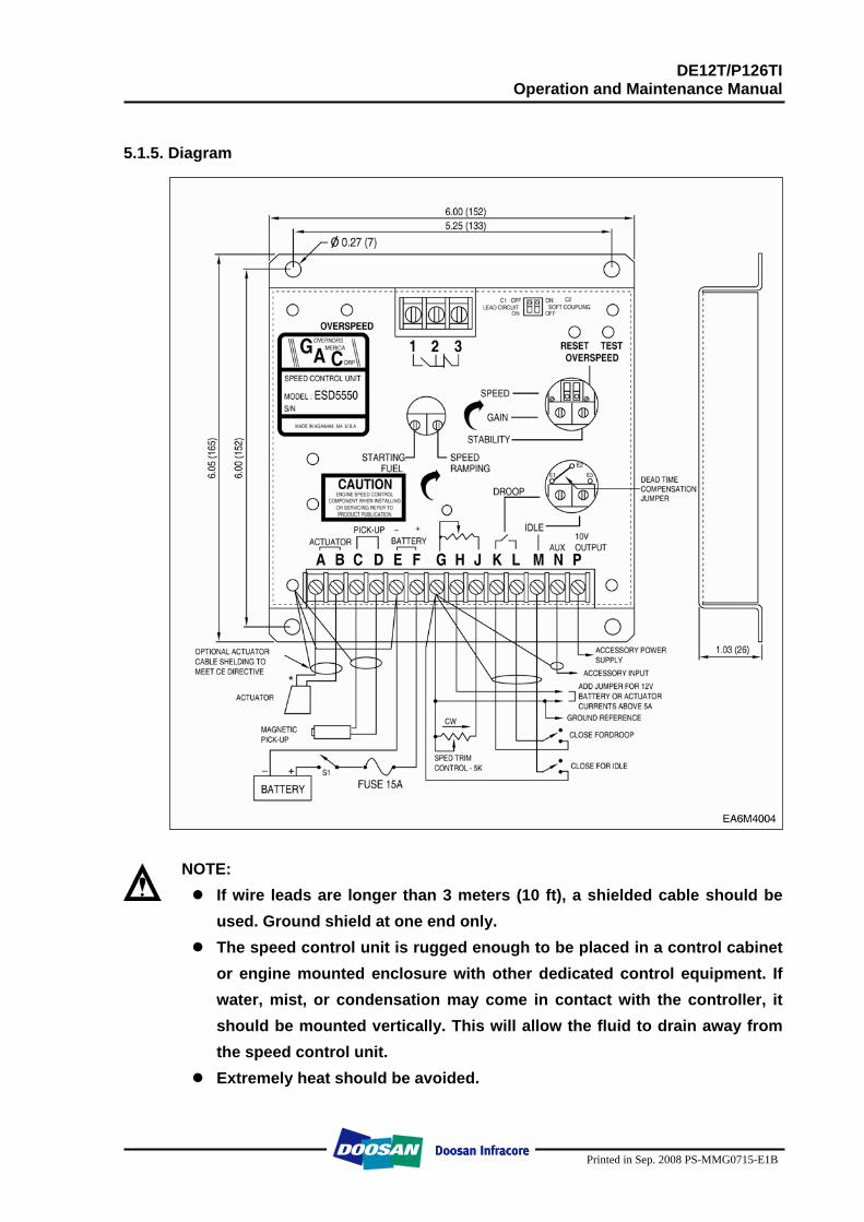
DE12T/P126TI Operation and Maintenance Manual
Printed in Sep. 2008 PS-MMG0715-E1B
5.1.5. Diagram
NOTE: If wire leads are longer than 3 meters (10 ft), a shielded cable should be
used. Ground shield at one end only. The speed control unit is rugged enough to be placed in a control cabinet
or engine mounted enclosure with other dedicated control equipment. If water, mist, or condensation may come in contact with the controller, it should be mounted vertically. This will allow the fluid to drain away from the speed control unit.
Extremely heat should be avoided.
DE12T/P126TI Operation and Maintenance Manual
Printed in Sep. 2008 PS-MMG0715-E1B
CAUTION: An overspeed shutdown device, independent of the governor system, should be provided to prevent loss of engine control which may cause personal injury or equipment damage. Do not rely exclusively on the governor system electric actuator to prevent overspeed. A secondary shutoff device, such as a fuel solenoid must be used.
5.1.5. Wiring Basic electrical connections are illustrated above. Actuator and battery
connections to Terminals A, B, E, and F should be #16 AWG (1.3 mm2) or larger. Long cables require an increased wire size to minimize voltage drops.
The battery positive (+) input, Terminal F, should be fused for 15 amps as illustrated.
Magnetic speed sensor connections to Terminals C and D MUST BE TWISTED AND/OR SHIELDED for their entire length. The speed sensor cable shield should only be connected to terminal D. The shield should be insulated to insure no other part of the shield comes in contact with engine ground, otherwise stray speed signals may be introduced to the speed control unit. With the engine stopped, adjust the gap between the magnetic speed sensor and the ring gear teeth. The gap should not be any smaller than 0.020 in, (0.45 mm). Usually, backing out the speed sensor 3/4 turn after touching the ring gear tooth will achieve a satisfactory air gap. The magnetic speed sensor voltage should be at least 1 VAC RMS during cranking.
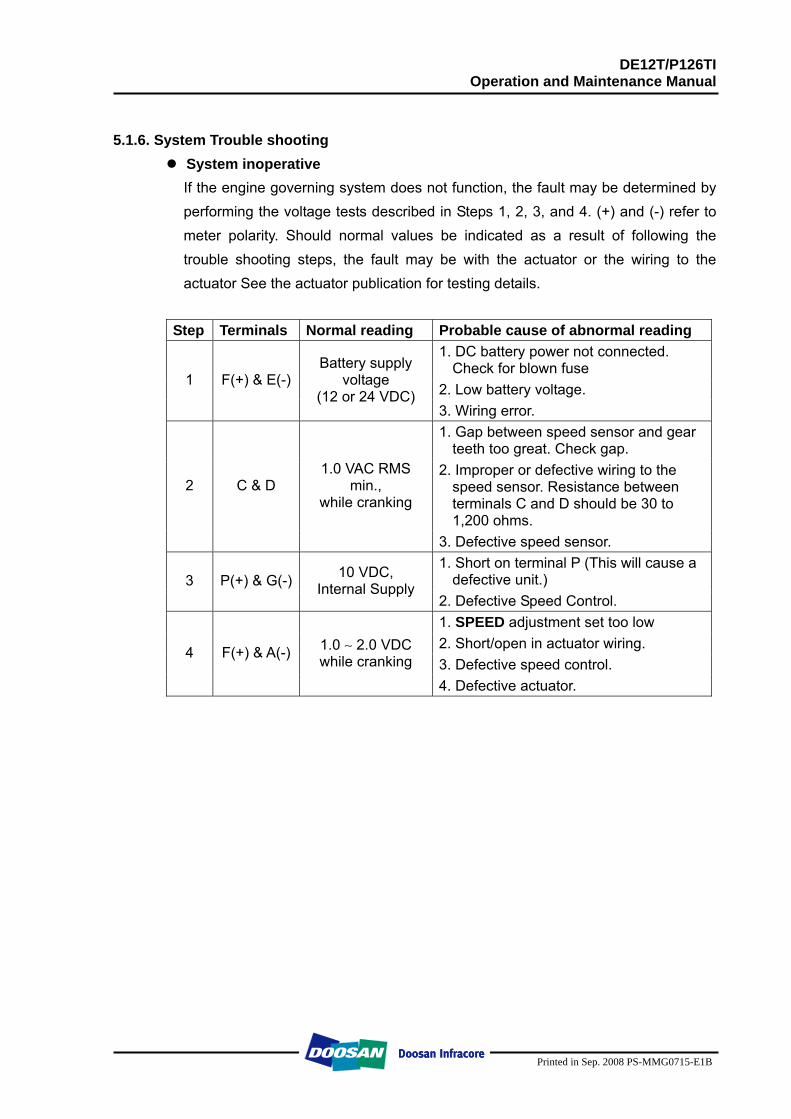
DE12T/P126TI Operation and Maintenance Manual
Printed in Sep. 2008 PS-MMG0715-E1B
5.1.6. System Trouble shooting
System inoperative If the engine governing system does not function, the fault may be determined by performing the voltage tests described in Steps 1, 2, 3, and 4. (+) and (-) refer to meter polarity. Should normal values be indicated as a result of following the trouble shooting steps, the fault may be with the actuator or the wiring to the actuator See the actuator publication for testing details.
Step Terminals Normal reading Probable cause of abnormal reading 1. DC battery power not connected.
Check for blown fuse 2. Low battery voltage.
1 F(+) & E(-) Battery supply
voltage (12 or 24 VDC)
3. Wiring error. 1. Gap between speed sensor and gear
teeth too great. Check gap. 2. Improper or defective wiring to the
speed sensor. Resistance between terminals C and D should be 30 to 1,200 ohms.
2 C & D 1.0 VAC RMS
min., while cranking
3. Defective speed sensor. 1. Short on terminal P (This will cause a
defective unit.) 3 P(+) & G(-) 10 VDC, Internal Supply
2. Defective Speed Control. 1. SPEED adjustment set too low 2. Short/open in actuator wiring. 3. Defective speed control.
4 F(+) & A(-) 1.0 ∼ 2.0 VDC while cranking
4. Defective actuator.
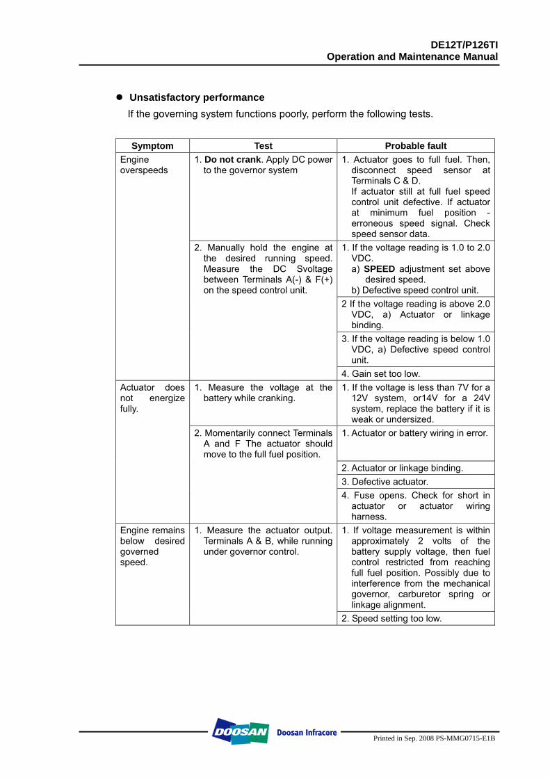
DE12T/P126TI Operation and Maintenance Manual
Printed in Sep. 2008 PS-MMG0715-E1B
Unsatisfactory performance If the governing system functions poorly, perform the following tests.
Symptom Test Probable fault 1. Do not crank. Apply DC power
to the governor system 1. Actuator goes to full fuel. Then,
disconnect speed sensor at Terminals C & D. If actuator still at full fuel speed control unit defective. If actuator at minimum fuel position - erroneous speed signal. Check speed sensor data.
2. Manually hold the engine at the desired running speed. Measure the DC Svoltage between Terminals A(-) & F(+) on the speed control unit.
1. If the voltage reading is 1.0 to 2.0 VDC. a) SPEED adjustment set above
desired speed. b) Defective speed control unit.
2 If the voltage reading is above 2.0 VDC, a) Actuator or linkage binding.
3. If the voltage reading is below 1.0 VDC, a) Defective speed control unit.
Engine overspeeds
4. Gain set too low. 1. Measure the voltage at the
battery while cranking. 1. If the voltage is less than 7V for a
12V system, or14V for a 24V system, replace the battery if it is weak or undersized.
2. Momentarily connect Terminals A and F The actuator should move to the full fuel position.
1. Actuator or battery wiring in error.
2. Actuator or linkage binding. 3. Defective actuator.
Actuator does not energize fully.
4. Fuse opens. Check for short in actuator or actuator wiring harness.
1. Measure the actuator output. Terminals A & B, while running under governor control.
1. If voltage measurement is within approximately 2 volts of the battery supply voltage, then fuel control restricted from reaching full fuel position. Possibly due to interference from the mechanical governor, carburetor spring or linkage alignment.
Engine remains below desired governed speed.
2. Speed setting too low.
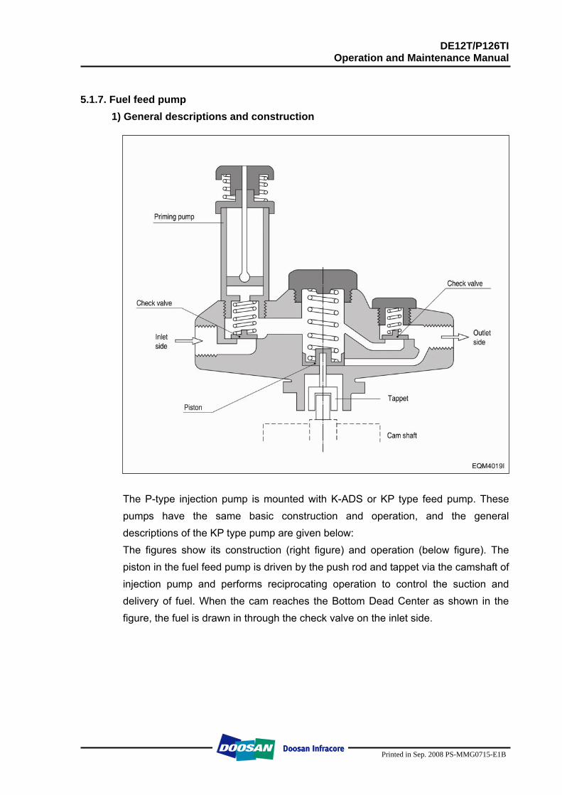
DE12T/P126TI Operation and Maintenance Manual
Printed in Sep. 2008 PS-MMG0715-E1B
5.1.7. Fuel feed pump
1) General descriptions and construction
The P-type injection pump is mounted with K-ADS or KP type feed pump. These pumps have the same basic construction and operation, and the general descriptions of the KP type pump are given below: The figures show its construction (right figure) and operation (below figure). The piston in the fuel feed pump is driven by the push rod and tappet via the camshaft of injection pump and performs reciprocating operation to control the suction and delivery of fuel. When the cam reaches the Bottom Dead Center as shown in the figure, the fuel is drawn in through the check valve on the inlet side.
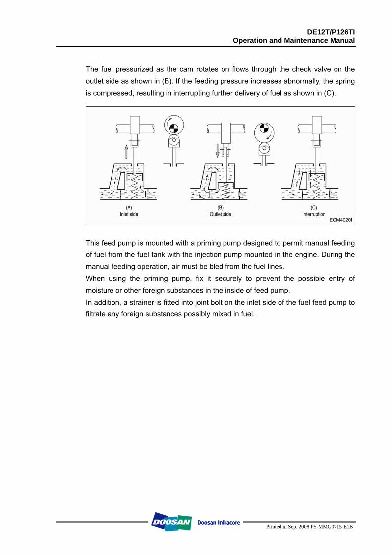
DE12T/P126TI Operation and Maintenance Manual
Printed in Sep. 2008 PS-MMG0715-E1B
The fuel pressurized as the cam rotates on flows through the check valve on the outlet side as shown in (B). If the feeding pressure increases abnormally, the spring is compressed, resulting in interrupting further delivery of fuel as shown in (C).
This feed pump is mounted with a priming pump designed to permit manual feeding of fuel from the fuel tank with the injection pump mounted in the engine. During the manual feeding operation, air must be bled from the fuel lines. When using the priming pump, fix it securely to prevent the possible entry of moisture or other foreign substances in the inside of feed pump. In addition, a strainer is fitted into joint bolt on the inlet side of the fuel feed pump to filtrate any foreign substances possibly mixed in fuel.
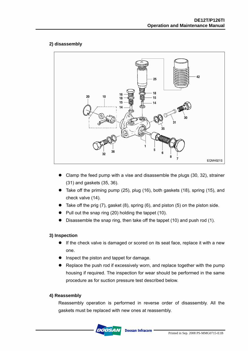
DE12T/P126TI Operation and Maintenance Manual
Printed in Sep. 2008 PS-MMG0715-E1B
2) disassembly
Clamp the feed pump with a vise and disassemble the plugs (30, 32), strainer
(31) and gaskets (35, 36). Take off the priming pump (25), plug (16), both gaskets (18), spring (15), and
check valve (14). Take off the prig (7), gasket (8), spring (6), and piston (5) on the piston side. Pull out the snap ring (20) holding the tappet (10). Disassemble the snap ring, then take off the tappet (10) and push rod (1).
3) Inspection
If the check valve is damaged or scored on its seat face, replace it with a new one.
Inspect the piston and tappet for damage. Replace the push rod if excessively worn, and replace together with the pump
housing if required. The inspection for wear should be performed in the same procedure as for suction pressure test described below.
4) Reassembly
Reassembly operation is performed in reverse order of disassembly. All the gaskets must be replaced with new ones at reassembly.
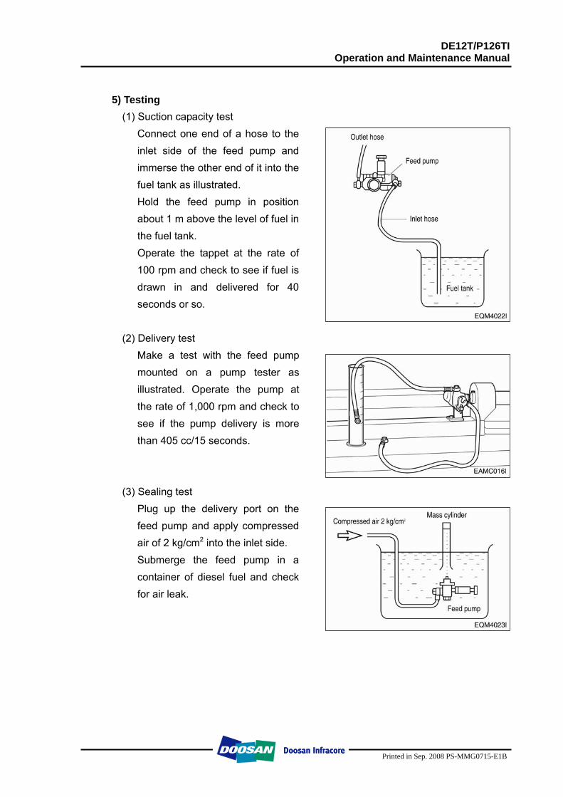
DE12T/P126TI Operation and Maintenance Manual
Printed in Sep. 2008 PS-MMG0715-E1B
5) Testing
(1) Suction capacity test Connect one end of a hose to the inlet side of the feed pump and immerse the other end of it into the fuel tank as illustrated. Hold the feed pump in position about 1 m above the level of fuel in the fuel tank. Operate the tappet at the rate of 100 rpm and check to see if fuel is drawn in and delivered for 40 seconds or so.
(2) Delivery test
Make a test with the feed pump mounted on a pump tester as illustrated. Operate the pump at the rate of 1,000 rpm and check to see if the pump delivery is more than 405 cc/15 seconds.
(3) Sealing test Plug up the delivery port on the feed pump and apply compressed air of 2 kg/cm2 into the inlet side. Submerge the feed pump in a container of diesel fuel and check for air leak.
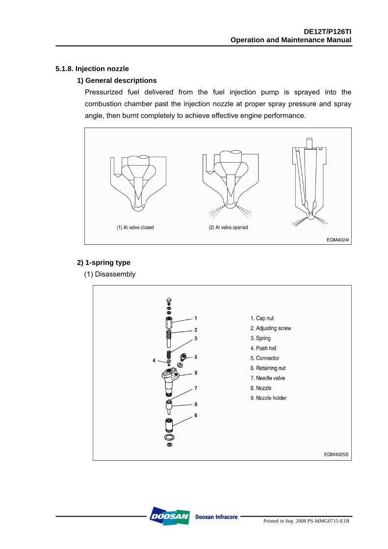
DE12T/P126TI Operation and Maintenance Manual
Printed in Sep. 2008 PS-MMG0715-E1B
5.1.8. Injection nozzle
1) General descriptions Pressurized fuel delivered from the fuel injection pump is sprayed into the combustion chamber past the injection nozzle at proper spray pressure and spray angle, then burnt completely to achieve effective engine performance.
2) 1-spring type
(1) Disassembly
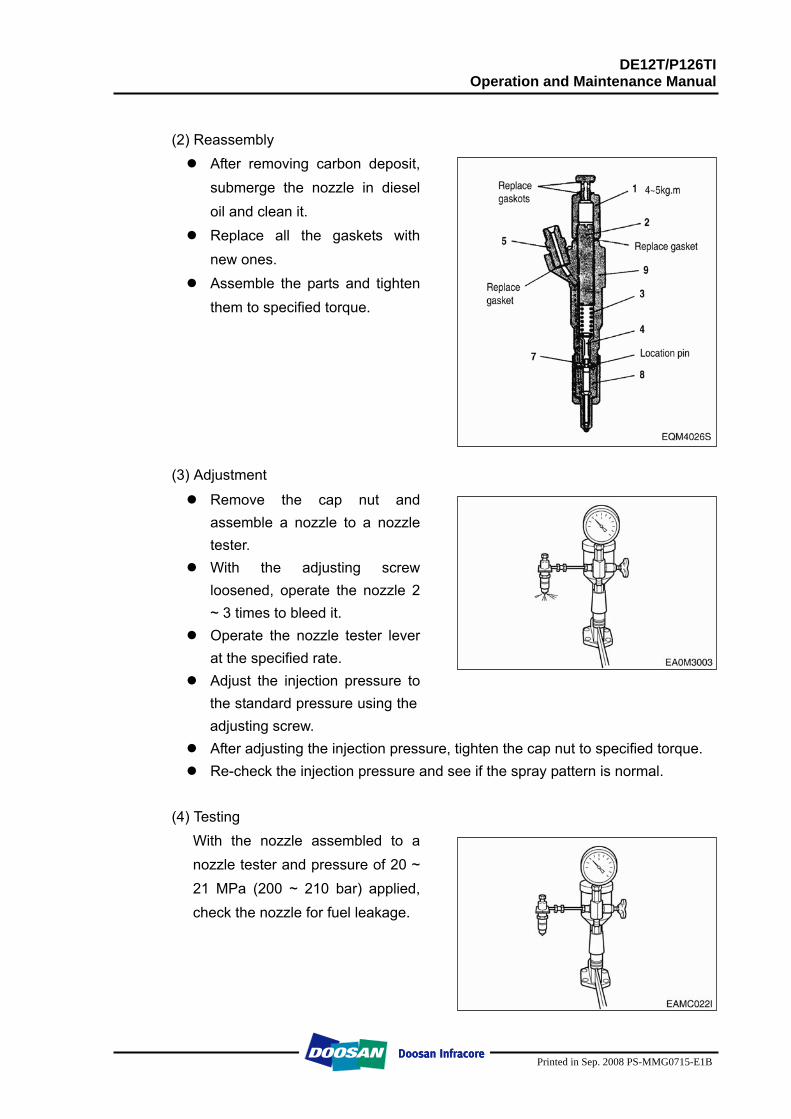
DE12T/P126TI Operation and Maintenance Manual
Printed in Sep. 2008 PS-MMG0715-E1B
(2) Reassembly
After removing carbon deposit, submerge the nozzle in diesel oil and clean it.
Replace all the gaskets with new ones.
Assemble the parts and tighten them to specified torque.
(3) Adjustment
Remove the cap nut and assemble a nozzle to a nozzle tester.
With the adjusting screw loosened, operate the nozzle 2 ~ 3 times to bleed it.
Operate the nozzle tester lever at the specified rate.
Adjust the injection pressure to the standard pressure using the adjusting screw.
After adjusting the injection pressure, tighten the cap nut to specified torque. Re-check the injection pressure and see if the spray pattern is normal.
(4) Testing
With the nozzle assembled to a nozzle tester and pressure of 20 ~ 21 MPa (200 ~ 210 bar) applied, check the nozzle for fuel leakage.
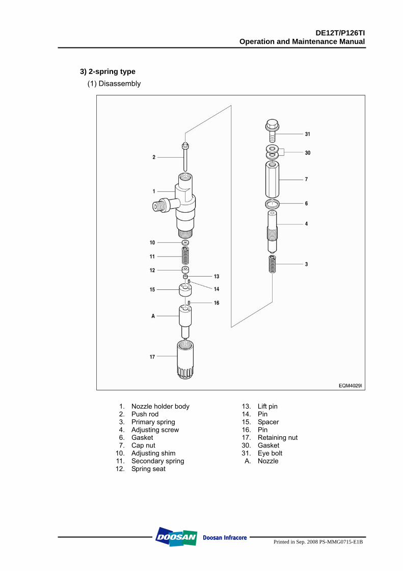
DE12T/P126TI Operation and Maintenance Manual
Printed in Sep. 2008 PS-MMG0715-E1B
3) 2-spring type
(1) Disassembly
1. Nozzle holder body 13. Lift pin 2. Push rod 14. Pin 3. Primary spring 15. Spacer 4. Adjusting screw 16. Pin 6. Gasket 17. Retaining nut 7. Cap nut 30. Gasket
10. Adjusting shim 31. Eye bolt 11. Secondary spring A. Nozzle 12. Spring seat
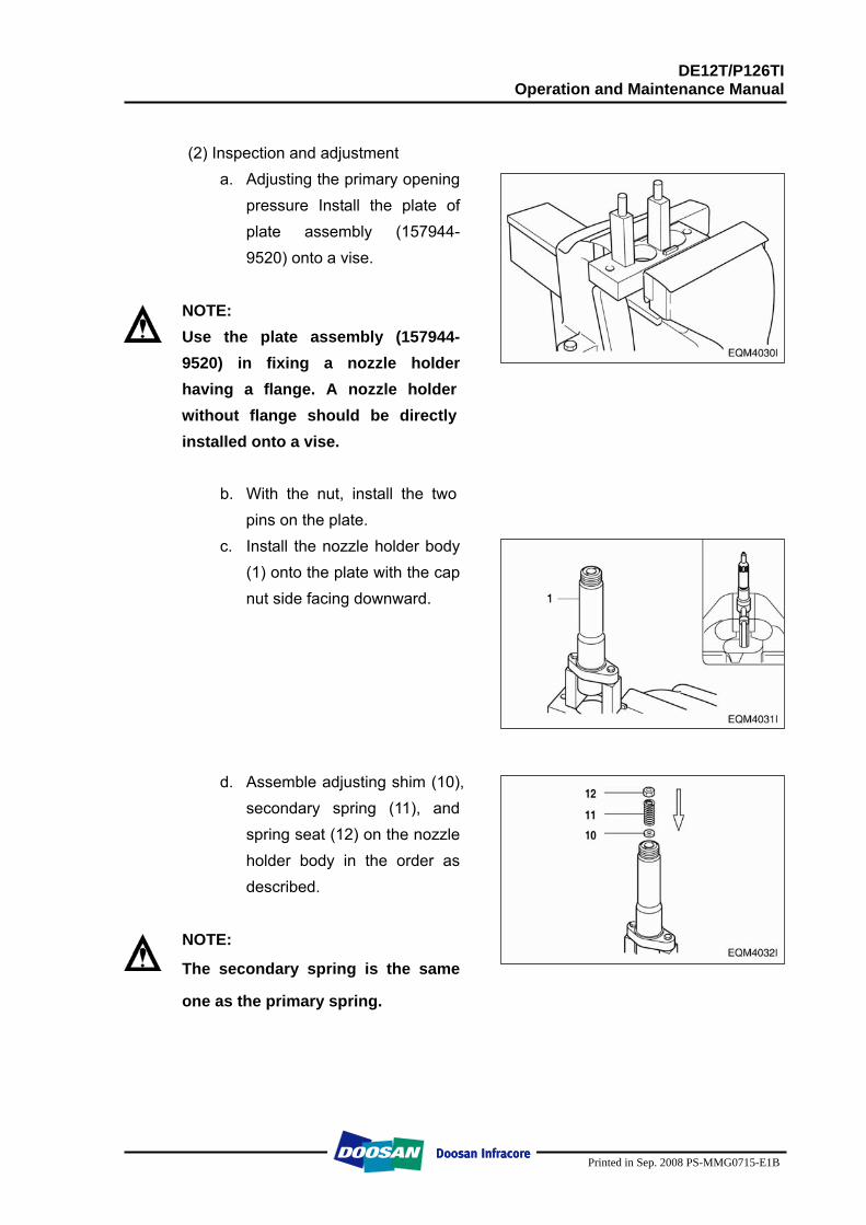
DE12T/P126TI Operation and Maintenance Manual
Printed in Sep. 2008 PS-MMG0715-E1B
(2) Inspection and adjustment
a. Adjusting the primary opening pressure Install the plate of plate assembly (157944-9520) onto a vise.
NOTE: Use the plate assembly (157944-9520) in fixing a nozzle holder having a flange. A nozzle holder without flange should be directly installed onto a vise.
b. With the nut, install the two pins on the plate.
c. Install the nozzle holder body (1) onto the plate with the cap nut side facing downward.
d. Assemble adjusting shim (10),
secondary spring (11), and spring seat (12) on the nozzle holder body in the order as described.
NOTE:
The secondary spring is the same
one as the primary spring.
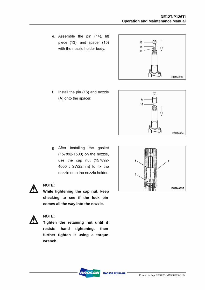
DE12T/P126TI Operation and Maintenance Manual
Printed in Sep. 2008 PS-MMG0715-E1B
e. Assemble the pin (14), lift
piece (13), and spacer (15) with the nozzle holder body.
f. Install the pin (16) and nozzle
(A) onto the spacer. g. After installing the gasket
(157892-1500) on the nozzle, use the cap nut (157892-4000 : SW22mm) to fix the nozzle onto the nozzle holder.
NOTE: While tightening the cap nut, keep checking to see if the lock pin comes all the way into the nozzle.
NOTE: Tighten the retaining nut until it resists hand tightening, then further tighten it using a torque wrench.
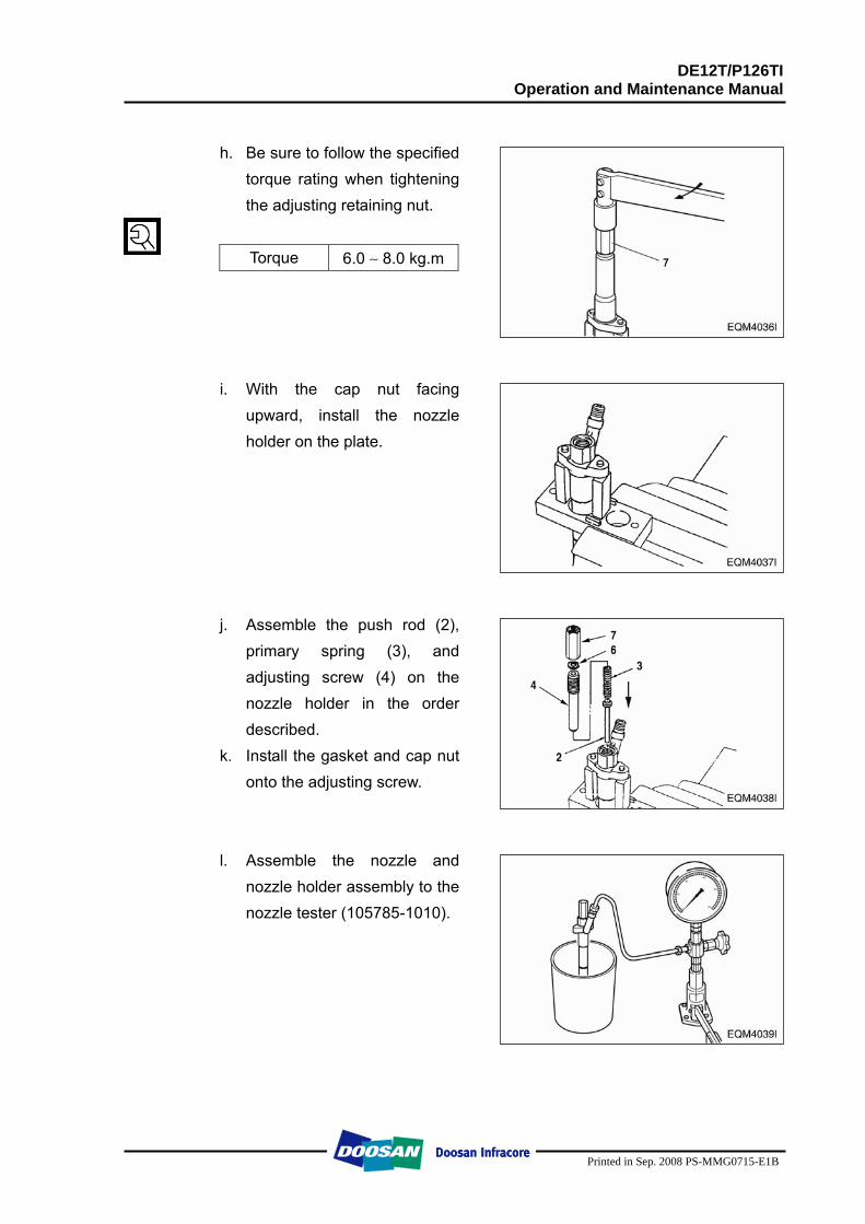
DE12T/P126TI Operation and Maintenance Manual
Printed in Sep. 2008 PS-MMG0715-E1B
h. Be sure to follow the specified
torque rating when tightening the adjusting retaining nut.
Torque 6.0 ∼ 8.0 kg.m
i. With the cap nut facing
upward, install the nozzle holder on the plate.
j. Assemble the push rod (2),
primary spring (3), and adjusting screw (4) on the nozzle holder in the order described.
k. Install the gasket and cap nut onto the adjusting screw.
l. Assemble the nozzle and
nozzle holder assembly to the nozzle tester (105785-1010).
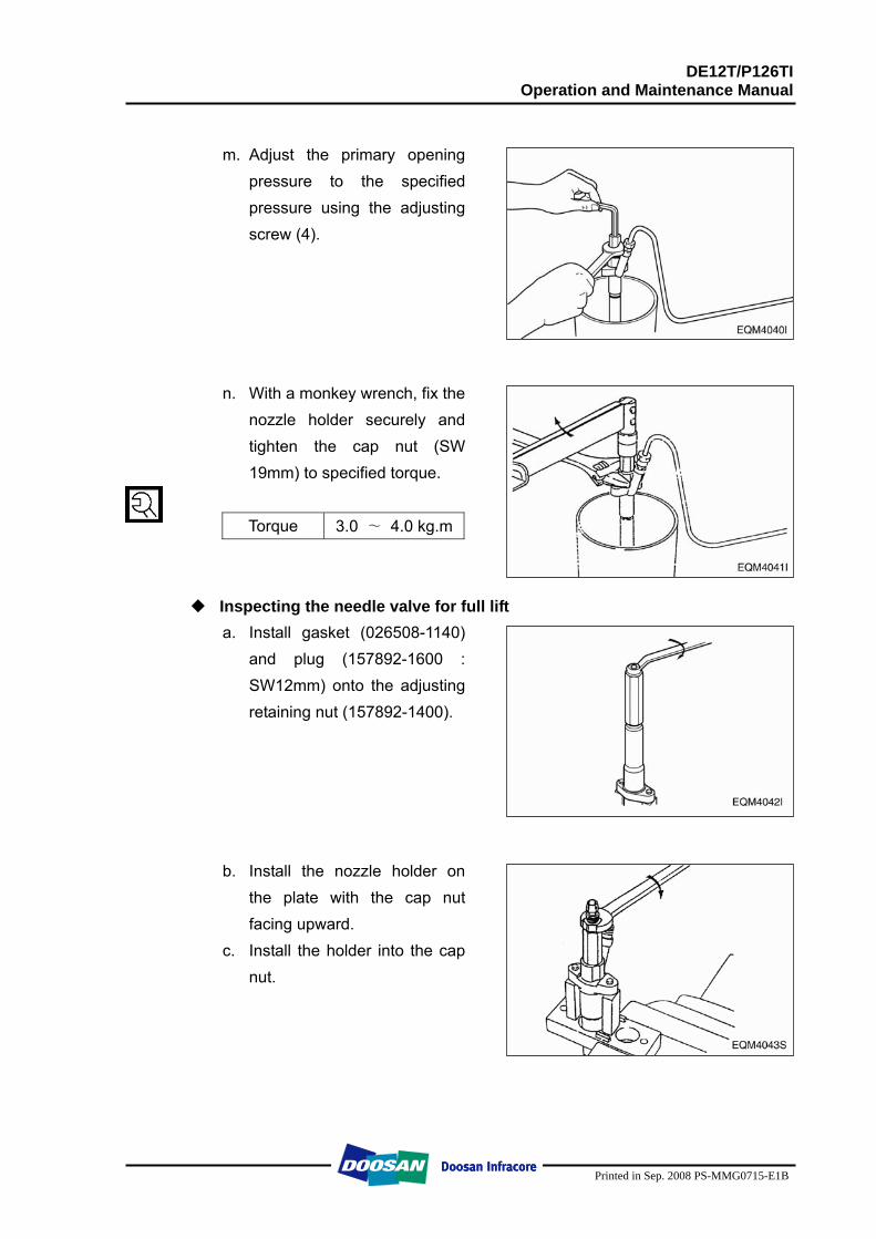
DE12T/P126TI Operation and Maintenance Manual
Printed in Sep. 2008 PS-MMG0715-E1B
m. Adjust the primary opening
pressure to the specified pressure using the adjusting screw (4).
n. With a monkey wrench, fix the
nozzle holder securely and tighten the cap nut (SW 19mm) to specified torque.
Torque 3.0 ∼ 4.0 kg.m
Inspecting the needle valve for full lift a. Install gasket (026508-1140)
and plug (157892-1600 : SW12mm) onto the adjusting retaining nut (157892-1400).
b. Install the nozzle holder on the plate with the cap nut facing upward.
c. Install the holder into the cap nut.
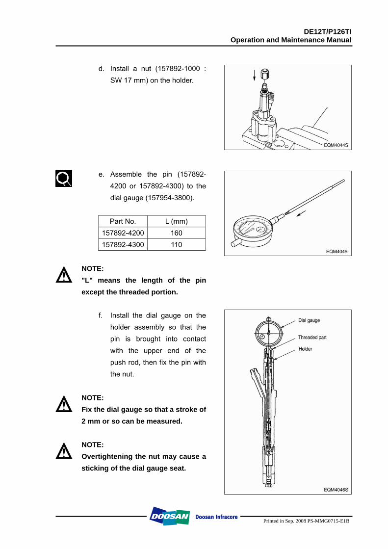
DE12T/P126TI Operation and Maintenance Manual
Printed in Sep. 2008 PS-MMG0715-E1B
d. Install a nut (157892-1000 :
SW 17 mm) on the holder.
e. Assemble the pin (157892-4200 or 157892-4300) to the dial gauge (157954-3800).
Part No. L (mm)
157892-4200 160 157892-4300 110
NOTE: "L" means the length of the pin except the threaded portion.
f. Install the dial gauge on the
holder assembly so that the pin is brought into contact with the upper end of the push rod, then fix the pin with the nut.
NOTE: Fix the dial gauge so that a stroke of 2 mm or so can be measured.
NOTE: Overtightening the nut may cause a sticking of the dial gauge seat.
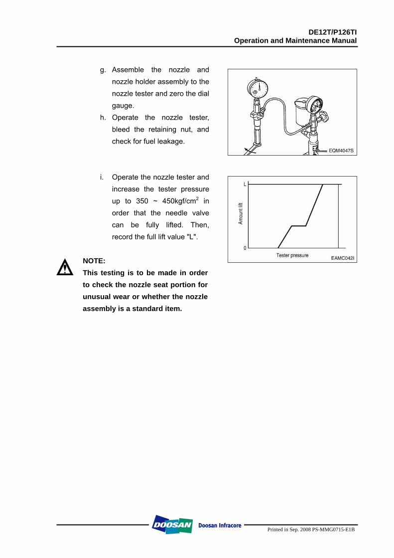
DE12T/P126TI Operation and Maintenance Manual
Printed in Sep. 2008 PS-MMG0715-E1B
g. Assemble the nozzle and
nozzle holder assembly to the nozzle tester and zero the dial gauge.
h. Operate the nozzle tester, bleed the retaining nut, and check for fuel leakage.
i. Operate the nozzle tester and increase the tester pressure up to 350 ~ 450kgf/cm2 in order that the needle valve can be fully lifted. Then, record the full lift value "L".
NOTE: This testing is to be made in order to check the nozzle seat portion for unusual wear or whether the nozzle assembly is a standard item.
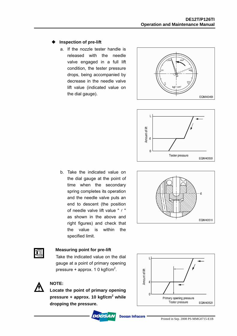
DE12T/P126TI Operation and Maintenance Manual
Printed in Sep. 2008 PS-MMG0715-E1B
Inspection of pre-lift
a. If the nozzle tester handle is released with the needle valve engaged in a full lift condition, the tester pressure drops, being accompanied by decrease in the needle valve lift value (indicated value on the dial gauge).
b. Take the indicated value on
the dial gauge at the point of time when the secondary spring completes its operation and the needle valve puts an end to descent (the position of needle valve lift value " l " as shown in the above and right figures) and check that the value is within the specified limit.
Measuring point for pre-lift Take the indicated value on the dial gauge at a point of primary opening pressure + approx. 1 0 kgf/cm2.
NOTE: Locate the point of primary opening pressure + approx. 10 kgf/cm2 while dropping the pressure.
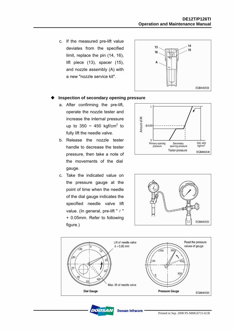
DE12T/P126TI Operation and Maintenance Manual
Printed in Sep. 2008 PS-MMG0715-E1B
c. If the measured pre-lift value
deviates from the specified limit, replace the pin (14, 16), lift piece (13), spacer (15), and nozzle assembly (A) with a new "nozzle service kit".
Inspection of secondary opening pressure a. After confirming the pre-lift,
operate the nozzle tester and increase the internal pressure up to 350 ~ 450 kgf/cm2 to fully lift the needle valve.
b. Release the nozzle tester handle to decrease the tester pressure, then take a note of the movements of the dial gauge.
c. Take the indicated value on the pressure gauge at the point of time when the needle of the dial gauge indicates the specified needle valve lift
value. (In general, pre-lift " l " + 0.05mm. Refer to following figure.)
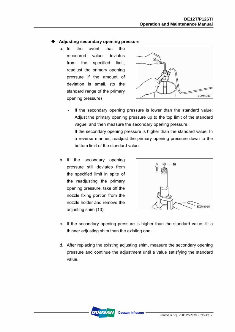
DE12T/P126TI Operation and Maintenance Manual
Printed in Sep. 2008 PS-MMG0715-E1B
Adjusting secondary opening pressure
a. In the event that the measured value deviates from the specified limit, readjust the primary opening pressure if the amount of deviation is small. (to the standard range of the primary opening pressure)
- If the secondary opening pressure is lower than the standard value:
Adjust the primary opening pressure up to the top limit of the standard vague, and then measure the secondary opening pressure.
- If the secondary opening pressure is higher than the standard value: In a reverse manner, readjust the primary opening pressure down to the bottom limit of the standard value.
b. If the secondary opening
pressure still deviates from the specified limit in spite of the readjusting the primary opening pressure, take off the nozzle fixing portion from the nozzle holder and remove the adjusting shim (10).
c. If the secondary opening pressure is higher than the standard value, fit a
thinner adjusting shim than the existing one.
d. After replacing the existing adjusting shim, measure the secondary opening pressure and continue the adjustment until a value satisfying the standard value.
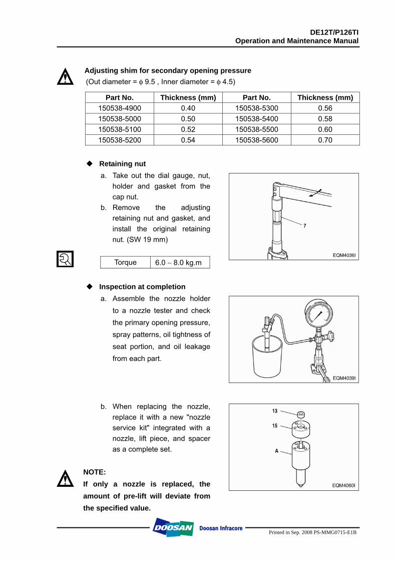
DE12T/P126TI Operation and Maintenance Manual
Printed in Sep. 2008 PS-MMG0715-E1B
Adjusting shim for secondary opening pressure (Out diameter = φ 9.5 , Inner diameter = φ 4.5)
Part No. Thickness (mm) Part No. Thickness (mm)
150538-4900 0.40 150538-5300 0.56 150538-5000 0.50 150538-5400 0.58 150538-5100 0.52 150538-5500 0.60 150538-5200 0.54 150538-5600 0.70
Retaining nut
a. Take out the dial gauge, nut, holder and gasket from the cap nut.
b. Remove the adjusting retaining nut and gasket, and install the original retaining nut. (SW 19 mm)
Torque 6.0 ∼ 8.0 kg.m
Inspection at completion
a. Assemble the nozzle holder to a nozzle tester and check the primary opening pressure, spray patterns, oil tightness of seat portion, and oil leakage from each part.
b. When replacing the nozzle, replace it with a new "nozzle service kit" integrated with a nozzle, lift piece, and spacer as a complete set.
NOTE: If only a nozzle is replaced, the amount of pre-lift will deviate from the specified value.
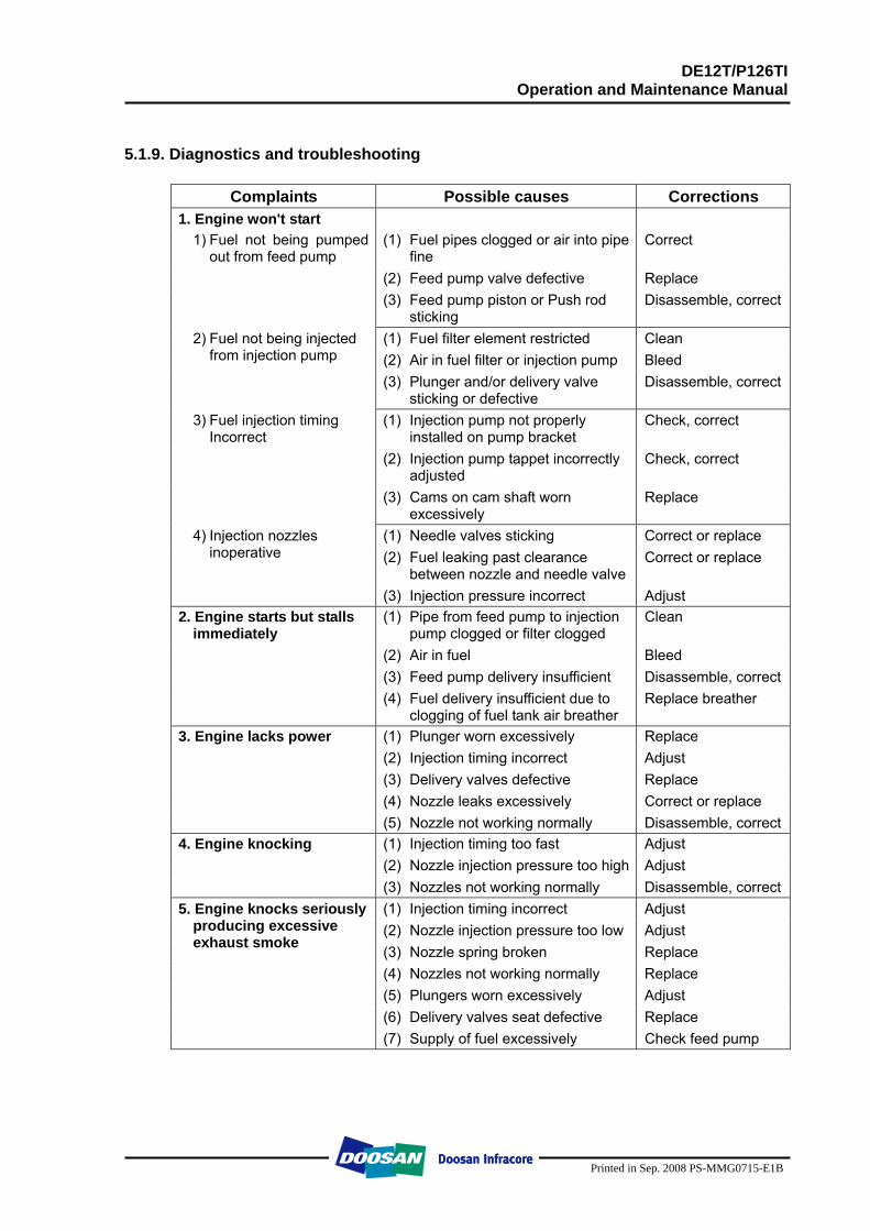
DE12T/P126TI Operation and Maintenance Manual
Printed in Sep. 2008 PS-MMG0715-E1B
5.1.9. Diagnostics and troubleshooting
Complaints Possible causes Corrections 1. Engine won't start
(1) Fuel pipes clogged or air into pipe fine
Correct
(2) Feed pump valve defective Replace
1) Fuel not being pumpedout from feed pump
(3) Feed pump piston or Push rod
sticking Disassemble, correct
(1) Fuel filter element restricted Clean (2) Air in fuel filter or injection pump Bleed
2) Fuel not being injected from injection pump
(3) Plunger and/or delivery valve sticking or defective
Disassemble, correct
(1) Injection pump not properly installed on pump bracket
Check, correct
(2) Injection pump tappet incorrectly adjusted
Check, correct
3) Fuel injection timing Incorrect
(3) Cams on cam shaft worn excessively
Replace
(1) Needle valves sticking Correct or replace (2) Fuel leaking past clearance
between nozzle and needle valve Correct or replace
4) Injection nozzles inoperative
(3) Injection pressure incorrect Adjust (1) Pipe from feed pump to injection
pump clogged or filter clogged Clean
(2) Air in fuel Bleed (3) Feed pump delivery insufficient Disassemble, correct
2. Engine starts but stalls immediately
(4) Fuel delivery insufficient due to clogging of fuel tank air breather
Replace breather
(1) Plunger worn excessively Replace (2) Injection timing incorrect Adjust (3) Delivery valves defective Replace (4) Nozzle leaks excessively Correct or replace
3. Engine lacks power
(5) Nozzle not working normally Disassemble, correct (1) Injection timing too fast Adjust (2) Nozzle injection pressure too high Adjust
4. Engine knocking (3) Nozzles not working normally Disassemble, correct
(1) Injection timing incorrect Adjust (2) Nozzle injection pressure too low Adjust (3) Nozzle spring broken Replace (4) Nozzles not working normally Replace (5) Plungers worn excessively Adjust (6) Delivery valves seat defective Replace
5. Engine knocks seriously producing excessive exhaust smoke
(7) Supply of fuel excessively Check feed pump
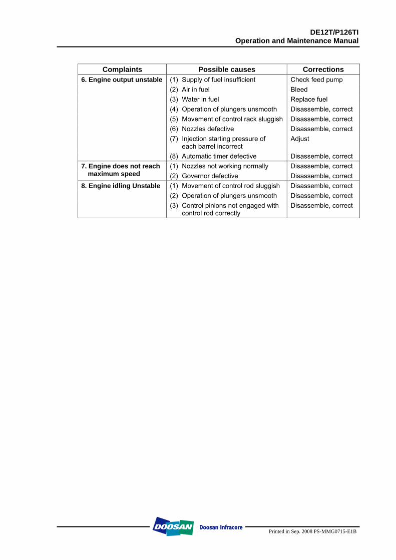
DE12T/P126TI Operation and Maintenance Manual
Printed in Sep. 2008 PS-MMG0715-E1B
Complaints Possible causes Corrections (1) Supply of fuel insufficient Check feed pump (2) Air in fuel Bleed (3) Water in fuel Replace fuel (4) Operation of plungers unsmooth Disassemble, correct (5) Movement of control rack sluggish Disassemble, correct (6) Nozzles defective Disassemble, correct (7) Injection starting pressure of
each barrel incorrect Adjust
6. Engine output unstable
(8) Automatic timer defective Disassemble, correct (1) Nozzles not working normally Disassemble, correct 7. Engine does not reach
maximum speed (2) Governor defective Disassemble, correct (1) Movement of control rod sluggish Disassemble, correct (2) Operation of plungers unsmooth Disassemble, correct
8. Engine idling Unstable (3) Control pinions not engaged with
control rod correctly Disassemble, correct
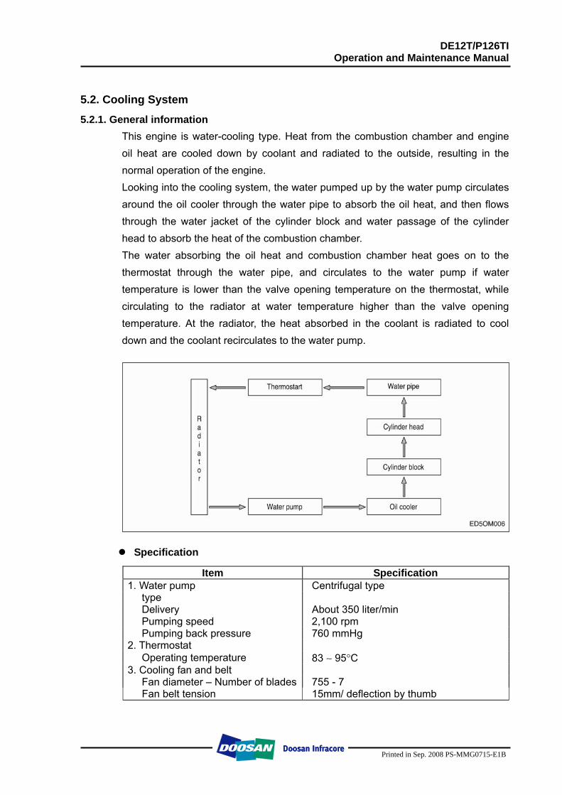
DE12T/P126TI Operation and Maintenance Manual
Printed in Sep. 2008 PS-MMG0715-E1B
5.2. Cooling System
5.2.1. General information This engine is water-cooling type. Heat from the combustion chamber and engine oil heat are cooled down by coolant and radiated to the outside, resulting in the normal operation of the engine. Looking into the cooling system, the water pumped up by the water pump circulates around the oil cooler through the water pipe to absorb the oil heat, and then flows through the water jacket of the cylinder block and water passage of the cylinder head to absorb the heat of the combustion chamber. The water absorbing the oil heat and combustion chamber heat goes on to the thermostat through the water pipe, and circulates to the water pump if water temperature is lower than the valve opening temperature on the thermostat, while circulating to the radiator at water temperature higher than the valve opening temperature. At the radiator, the heat absorbed in the coolant is radiated to cool down and the coolant recirculates to the water pump.
Specification
Item Specification 1. Water pump Centrifugal type
type Delivery About 350 liter/min Pumping speed 2,100 rpm Pumping back pressure 760 mmHg
2. Thermostat Operating temperature 83 ∼ 95°C
3. Cooling fan and belt Fan diameter – Number of blades 755 - 7 Fan belt tension 15mm/ deflection by thumb
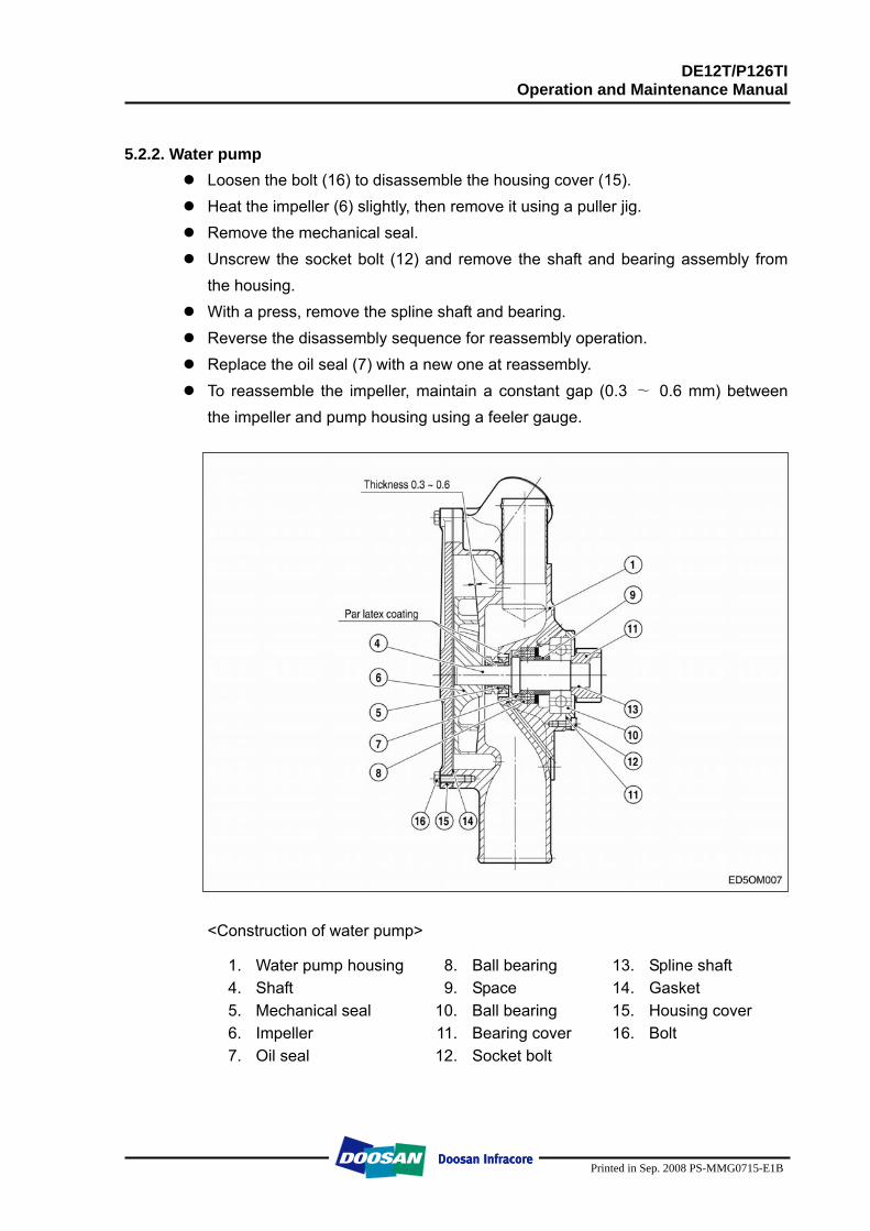
DE12T/P126TI Operation and Maintenance Manual
Printed in Sep. 2008 PS-MMG0715-E1B
5.2.2. Water pump
Loosen the bolt (16) to disassemble the housing cover (15). Heat the impeller (6) slightly, then remove it using a puller jig. Remove the mechanical seal. Unscrew the socket bolt (12) and remove the shaft and bearing assembly from
the housing. With a press, remove the spline shaft and bearing. Reverse the disassembly sequence for reassembly operation. Replace the oil seal (7) with a new one at reassembly. To reassemble the impeller, maintain a constant gap (0.3 ∼ 0.6 mm) between
the impeller and pump housing using a feeler gauge.
<Construction of water pump>
1. Water pump housing 8. Ball bearing 13. Spline shaft 4. Shaft 9. Space 14. Gasket 5. Mechanical seal 10. Ball bearing 15. Housing cover 6. Impeller 11. Bearing cover 16. Bolt 7. Oil seal 12. Socket bolt
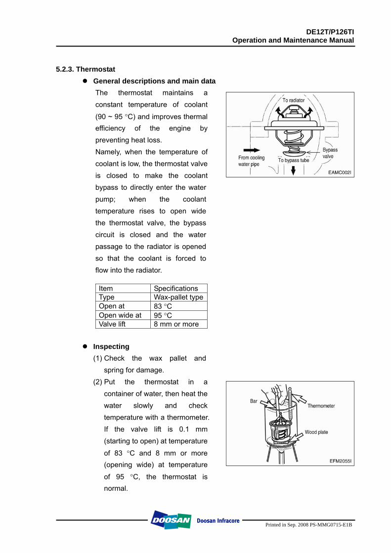
DE12T/P126TI Operation and Maintenance Manual
Printed in Sep. 2008 PS-MMG0715-E1B
5.2.3. Thermostat
General descriptions and main data The thermostat maintains a constant temperature of coolant
(90 ~ 95 °C) and improves thermal efficiency of the engine by preventing heat loss. Namely, when the temperature of coolant is low, the thermostat valve is closed to make the coolant bypass to directly enter the water pump; when the coolant temperature rises to open wide the thermostat valve, the bypass circuit is closed and the water passage to the radiator is opened so that the coolant is forced to flow into the radiator.
Item Specifications Type Wax-pallet typeOpen at 83 °C Open wide at 95 °C Valve lift 8 mm or more
Inspecting
(1) Check the wax pallet and spring for damage.
(2) Put the thermostat in a container of water, then heat the water slowly and check temperature with a thermometer. If the valve lift is 0.1 mm (starting to open) at temperature
of 83 °C and 8 mm or more (opening wide) at temperature
of 95 °C, the thermostat is normal.
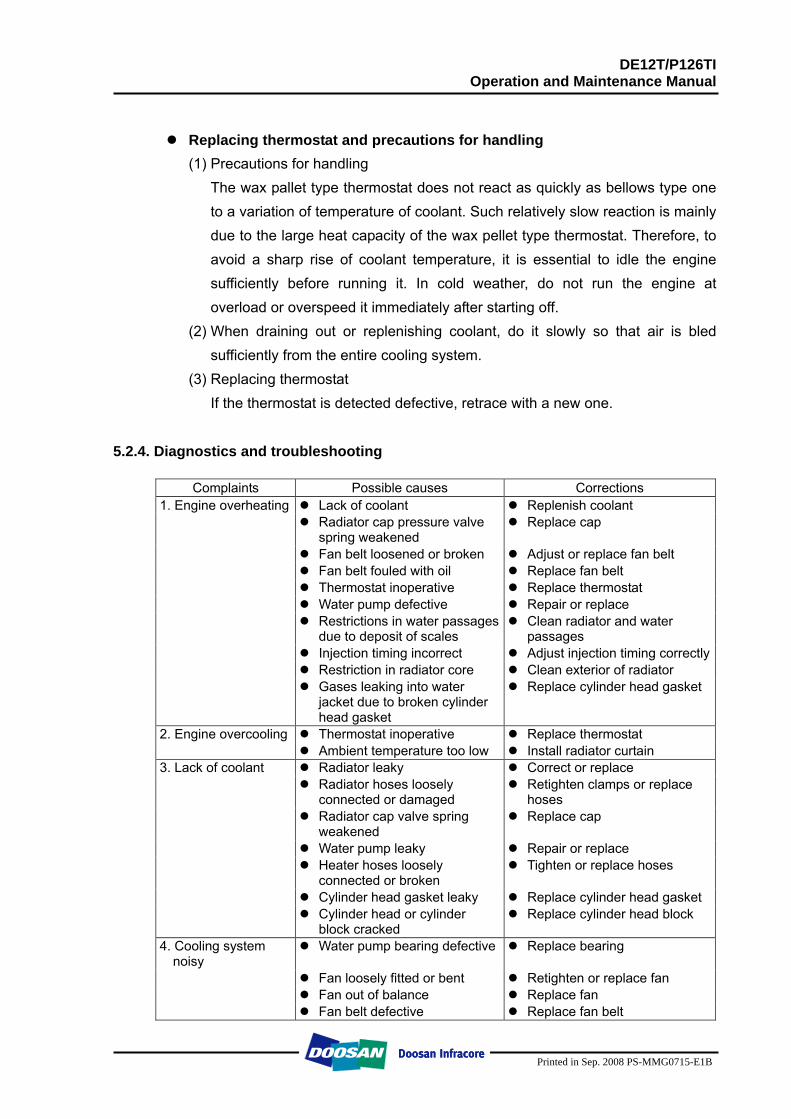
DE12T/P126TI Operation and Maintenance Manual
Printed in Sep. 2008 PS-MMG0715-E1B
Replacing thermostat and precautions for handling
(1) Precautions for handling The wax pallet type thermostat does not react as quickly as bellows type one to a variation of temperature of coolant. Such relatively slow reaction is mainly due to the large heat capacity of the wax pellet type thermostat. Therefore, to avoid a sharp rise of coolant temperature, it is essential to idle the engine sufficiently before running it. In cold weather, do not run the engine at overload or overspeed it immediately after starting off.
(2) When draining out or replenishing coolant, do it slowly so that air is bled sufficiently from the entire cooling system.
(3) Replacing thermostat If the thermostat is detected defective, retrace with a new one.
5.2.4. Diagnostics and troubleshooting
Complaints Possible causes Corrections 1. Engine overheating Lack of coolant Replenish coolant Radiator cap pressure valve
spring weakened Replace cap
Fan belt loosened or broken Adjust or replace fan belt Fan belt fouled with oil Replace fan belt Thermostat inoperative Replace thermostat Water pump defective Repair or replace Restrictions in water passages
due to deposit of scales Clean radiator and water
passages Injection timing incorrect Adjust injection timing correctly Restriction in radiator core Clean exterior of radiator Gases leaking into water
jacket due to broken cylinder head gasket
Replace cylinder head gasket
2. Engine overcooling Thermostat inoperative Replace thermostat Ambient temperature too low Install radiator curtain 3. Lack of coolant Radiator leaky Correct or replace Radiator hoses loosely
connected or damaged Retighten clamps or replace
hoses Radiator cap valve spring
weakened Replace cap
Water pump leaky Repair or replace Heater hoses loosely
connected or broken Tighten or replace hoses
Cylinder head gasket leaky Replace cylinder head gasket Cylinder head or cylinder
block cracked Replace cylinder head block
4. Cooling system noisy
Water pump bearing defective Replace bearing
Fan loosely fitted or bent Retighten or replace fan Fan out of balance Replace fan Fan belt defective Replace fan belt
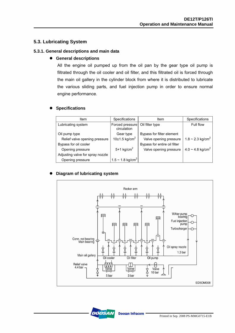
DE12T/P126TI Operation and Maintenance Manual
Printed in Sep. 2008 PS-MMG0715-E1B
5.3. Lubricating System
5.3.1. General descriptions and main data General descriptions
All the engine oil pumped up from the oil pan by the gear type oil pump is filtrated through the oil cooler and oil filter, and this filtrated oil is forced through the main oil gallery in the cylinder block from where it is distributed to lubricate the various sliding parts, and fuel injection pump in order to ensure normal engine performance.
Specifications
Item Specifications Item Specifications
Lubricating system Forced pressurecirculation
Oil filter type Full flow
Oil pump type Gear type Bypass for filter element Relief valve opening pressure 10±1.5 kg/cm2 Valve opening pressure 1.8 ~ 2.3 kg/cm2
Bypass for oil cooler Bypass for entire oil filter Opening pressure 5+1 kg/cm2 Valve opening pressure 4.0 ~ 4.8 kg/cm2
Adjusting valve for spray nozzle Opening pressure 1.5 ~ 1.8 kg/cm2
Diagram of lubricating system
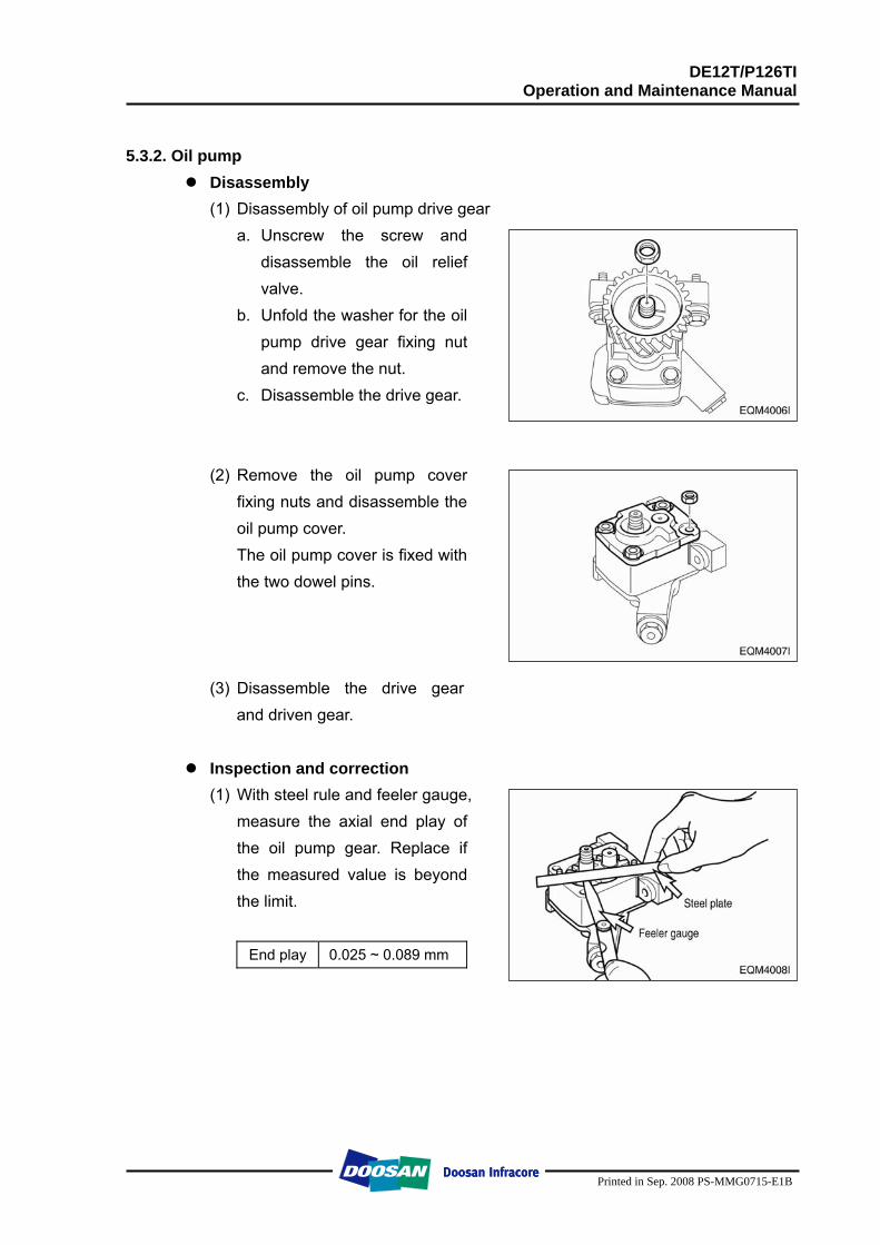
DE12T/P126TI Operation and Maintenance Manual
Printed in Sep. 2008 PS-MMG0715-E1B
5.3.2. Oil pump
Disassembly (1) Disassembly of oil pump drive gear
a. Unscrew the screw and disassemble the oil relief valve.
b. Unfold the washer for the oil pump drive gear fixing nut and remove the nut.
c. Disassemble the drive gear.
(2) Remove the oil pump cover fixing nuts and disassemble the oil pump cover. The oil pump cover is fixed with the two dowel pins.
(3) Disassemble the drive gear and driven gear.
Inspection and correction
(1) With steel rule and feeler gauge, measure the axial end play of the oil pump gear. Replace if the measured value is beyond the limit.
End play 0.025 ~ 0.089 mm
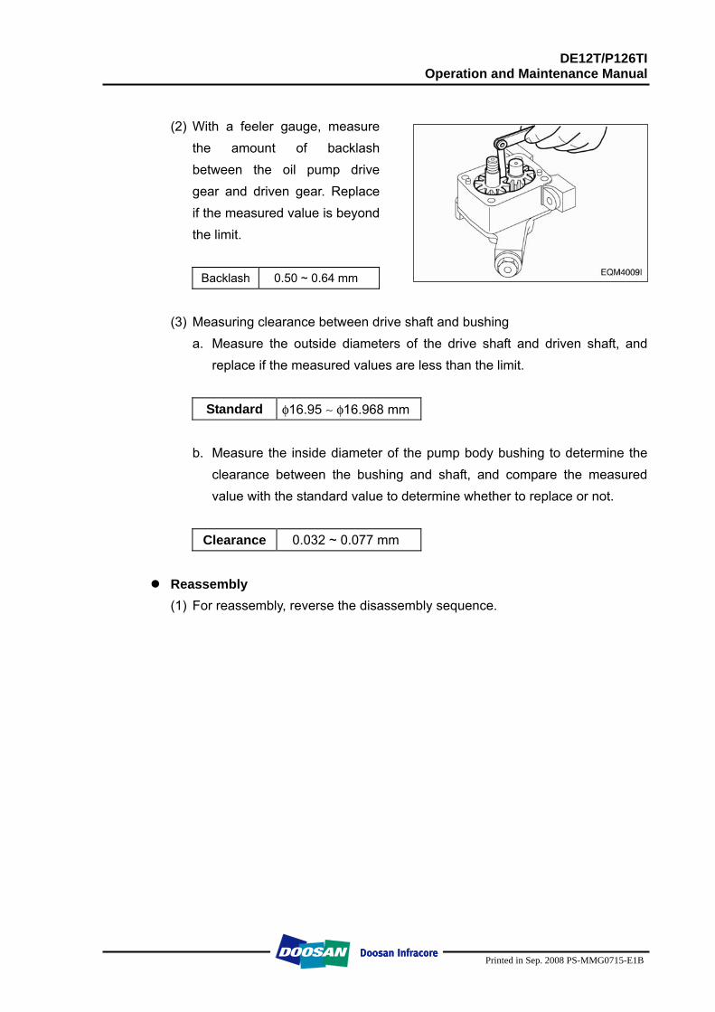
DE12T/P126TI Operation and Maintenance Manual
Printed in Sep. 2008 PS-MMG0715-E1B
(2) With a feeler gauge, measure
the amount of backlash between the oil pump drive gear and driven gear. Replace if the measured value is beyond the limit.
Backlash 0.50 ~ 0.64 mm
(3) Measuring clearance between drive shaft and bushing
a. Measure the outside diameters of the drive shaft and driven shaft, and replace if the measured values are less than the limit.
Standard φ16.95 ∼ φ16.968 mm
b. Measure the inside diameter of the pump body bushing to determine the clearance between the bushing and shaft, and compare the measured value with the standard value to determine whether to replace or not.
Clearance 0.032 ~ 0.077 mm
Reassembly
(1) For reassembly, reverse the disassembly sequence.
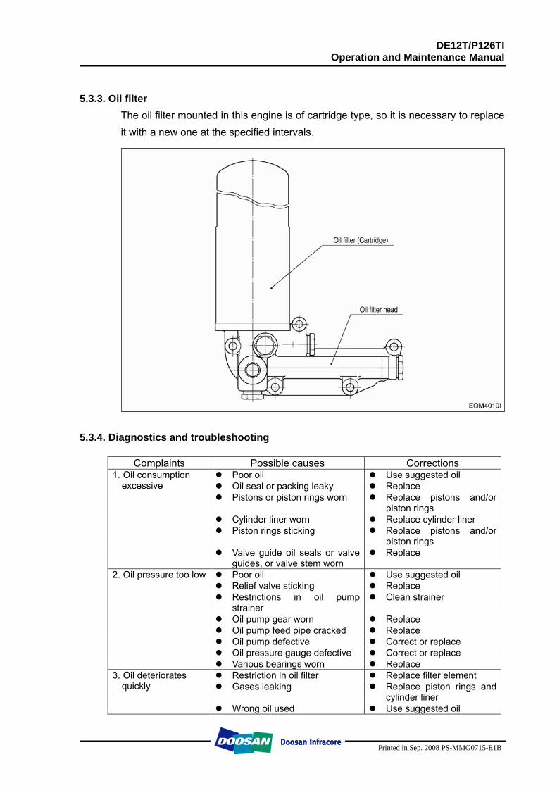
DE12T/P126TI Operation and Maintenance Manual
Printed in Sep. 2008 PS-MMG0715-E1B
5.3.3. Oil filter
The oil filter mounted in this engine is of cartridge type, so it is necessary to replace it with a new one at the specified intervals.
5.3.4. Diagnostics and troubleshooting
Complaints Possible causes Corrections Poor oil Use suggested oil Oil seal or packing leaky Replace Pistons or piston rings worn Replace pistons and/or
piston rings Cylinder liner worn Replace cylinder liner Piston rings sticking Replace pistons and/or
piston rings
1. Oil consumption excessive
Valve guide oil seals or valve guides, or valve stem worn
Replace
Poor oil Use suggested oil Relief valve sticking Replace Restrictions in oil pump
strainer Clean strainer
Oil pump gear worn Replace Oil pump feed pipe cracked Replace Oil pump defective Correct or replace Oil pressure gauge defective Correct or replace
2. Oil pressure too low
Various bearings worn Replace Restriction in oil filter Replace filter element Gases leaking Replace piston rings and
cylinder liner
3. Oil deteriorates quickly Wrong oil used Use suggested oil
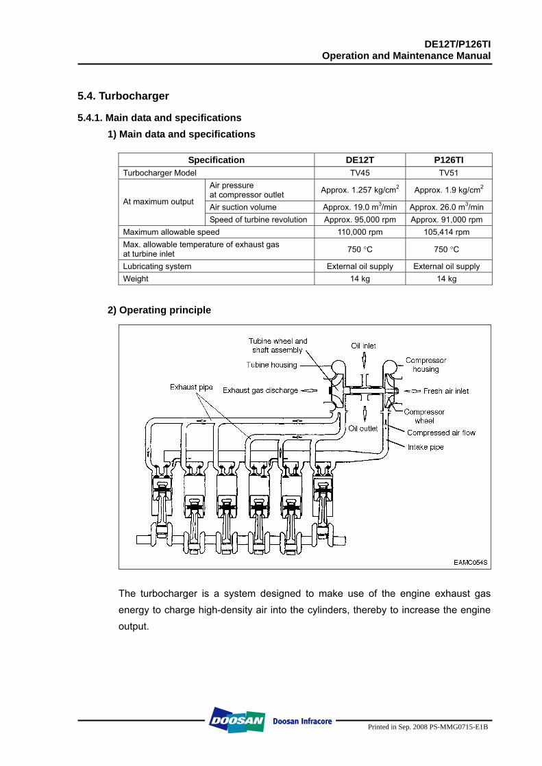
DE12T/P126TI Operation and Maintenance Manual
Printed in Sep. 2008 PS-MMG0715-E1B
5.4. Turbocharger
5.4.1. Main data and specifications 1) Main data and specifications
Specification DE12T P126TI
Turbocharger Model TV45 TV51 Air pressure at compressor outlet Approx. 1.257 kg/cm2 Approx. 1.9 kg/cm2
Air suction volume Approx. 19.0 m3/min Approx. 26.0 m3/min At maximum output
Speed of turbine revolution Approx. 95,000 rpm Approx. 91,000 rpm Maximum allowable speed 110,000 rpm 105,414 rpm Max. allowable temperature of exhaust gas at turbine inlet 750 °C 750 °C
Lubricating system External oil supply External oil supply Weight 14 kg 14 kg
2) Operating principle
The turbocharger is a system designed to make use of the engine exhaust gas energy to charge high-density air into the cylinders, thereby to increase the engine output.

DE12T/P126TI Operation and Maintenance Manual
Printed in Sep. 2008 PS-MMG0715-E1B
3) Construction
1 Turbine housing 15 Retainer ring 25 Bolt 2 Plug 16 Bearing 26 O-ring 5 Crank 17 Thrust collar 27 Compressor wheel 7 V-band 18 Screw 28 Nut 8 Wheel 19 Thrust bearing 29 Bolt 9 Piston ring 20 Thrust space 30 Clamp 10 Wheel shroud 21 Piston ring 31 Compressor housing 11 Center housing 22 Seal ring 32 Elbow 12 Retainer ring 23 Seal ring 38 Retainer 13 Bearing 24 Rear plate 45 Bolt 14 Retainer ring
DE12T/P126TI Operation and Maintenance Manual
Printed in Sep. 2008 PS-MMG0715-E1B
5.4.2. General descriptions
The engine output is determined by the fuel delivery volume and engine efficiency. To burn the supplied fuel completely to change into effective power for the engine, the volume of air enough to burn the fuel completely should be supplied into the cylinders. Therefore, the engine output is determined substantially by the cylinder capacity, and a greater volume of compressed air is charged into cylinders of given capacity, the greater engine output can be obtained as a greater volume of air charged into the cylinders burns so much more fuel. As explained, the compressing of air to supply into the cylinders is called "Supercharging" and the making use of the energy of exhaust gas discharged from the combustion chamber to charge the compressed air into the cylinders is called "Turbocharging".
5.4.3. Functions
1) Turbine Exhaust gas discharged from the combustion chamber distributes its own energy to the turbine blades while passing the inside of the turbine housing, with the result that the turbine shaft can get rotating force. This is the operating principle of 'turbine', which is mounted with seal rings and heat protector to prevent exhaust gas from affecting the bearings adversely.
2) Compressor
The compressor, which is connected to the turbine over the one and same shaft to form a rotating body, takes in and compresses ambient air with rotating force transmitted from the turbine shaft. Then, the compressed air is delivered to the intake stake. This is the operating principle of the compressor.
3) Bearings
(1) Thrust bearing The turbine wheel creates thrust force. Therefore, exercise care so that the shaft is not deviated from its the original position due to this thrust.
(2) Journal bearing
This journal bearing of floating type forms a dual oil film on both the inside and outside of the bearing so that the bearing can rotate independently. As the dual oil film plays a role as a damper, the sliding speed of the bearing surface becomes lower than the rotating speed of the shaft, resulting in assurance of stability in its movement.
4) Sealing-Compressor shaft
The compressor is of a dual construction type composed of seal plate and seal ring to prevent the leak of compressed air or lubricating oil.
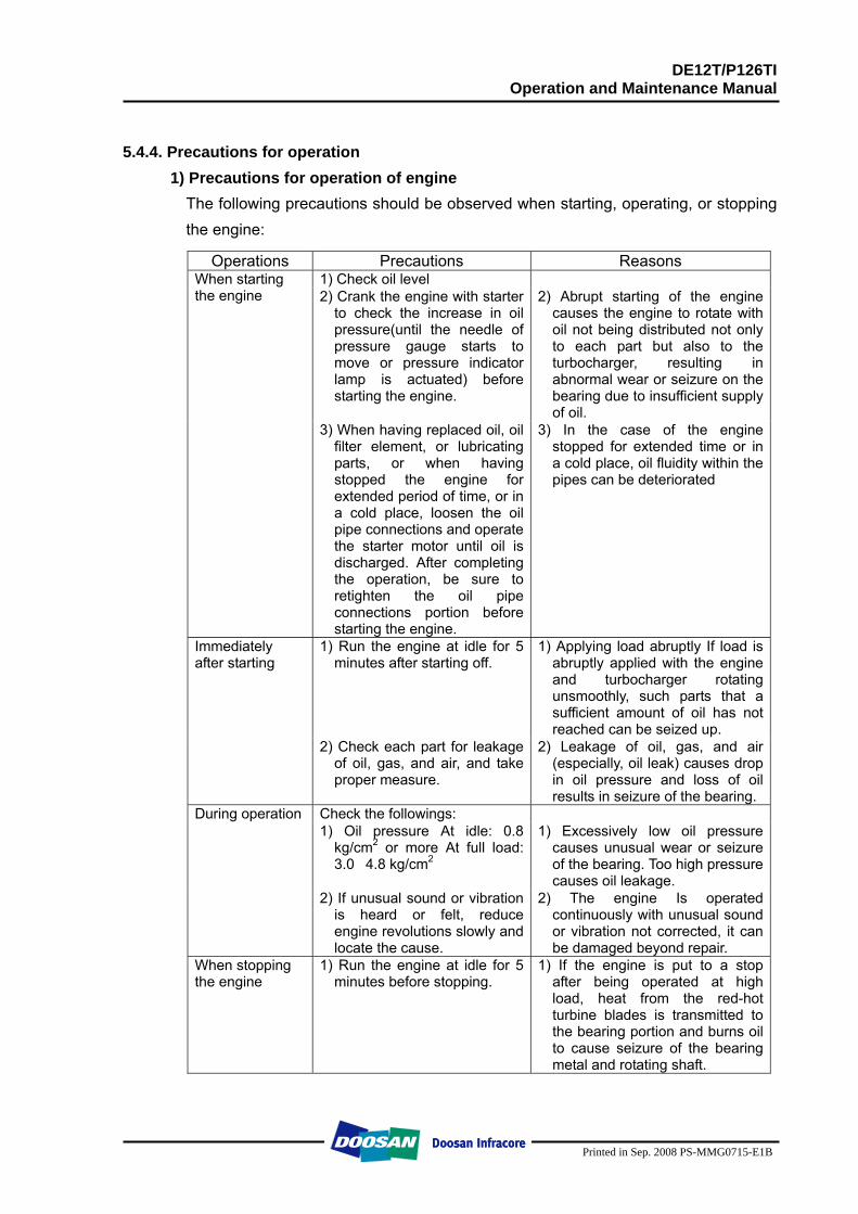
DE12T/P126TI Operation and Maintenance Manual
Printed in Sep. 2008 PS-MMG0715-E1B
5.4.4. Precautions for operation
1) Precautions for operation of engine The following precautions should be observed when starting, operating, or stopping the engine:
Operations Precautions Reasons 1) Check oil level 2) Crank the engine with starter
to check the increase in oil pressure(until the needle of pressure gauge starts to move or pressure indicator lamp is actuated) before starting the engine.
2) Abrupt starting of the engine causes the engine to rotate with oil not being distributed not only to each part but also to the turbocharger, resulting in abnormal wear or seizure on the bearing due to insufficient supply of oil.
When starting the engine
3) When having replaced oil, oil filter element, or lubricating parts, or when having stopped the engine for extended period of time, or in a cold place, loosen the oil pipe connections and operate the starter motor until oil is discharged. After completing the operation, be sure to retighten the oil pipe connections portion before starting the engine.
3) In the case of the engine stopped for extended time or in a cold place, oil fluidity within the pipes can be deteriorated
1) Run the engine at idle for 5 minutes after starting off.
1) Applying load abruptly If load is abruptly applied with the engine and turbocharger rotating unsmoothly, such parts that a sufficient amount of oil has not reached can be seized up.
Immediately after starting
2) Check each part for leakage of oil, gas, and air, and take proper measure.
2) Leakage of oil, gas, and air (especially, oil leak) causes drop in oil pressure and loss of oil results in seizure of the bearing.
Check the followings: 1) Oil pressure At idle: 0.8
kg/cm2 or more At full load: 3.0�4.8 kg/cm2
1) Excessively low oil pressure causes unusual wear or seizure of the bearing. Too high pressure causes oil leakage.
During operation
2) If unusual sound or vibration is heard or felt, reduce engine revolutions slowly and locate the cause.
2) The engine Is operated continuously with unusual sound or vibration not corrected, it can be damaged beyond repair.
When stopping the engine
1) Run the engine at idle for 5 minutes before stopping.
1) If the engine is put to a stop after being operated at high load, heat from the red-hot turbine blades is transmitted to the bearing portion and burns oil to cause seizure of the bearing metal and rotating shaft.
DE12T/P126TI Operation and Maintenance Manual
Printed in Sep. 2008 PS-MMG0715-E1B
5.4.5. Walk-around check and servicing
As the condition of turbocharger depends greatly on how well the engine is serviced, it is very important to maintain the engine in accordance with the specified maintenance procedure. 1) Intake system
Pay particular attention to the air cleaner when servicing the intake system. In the case of wet-type air cleaner, if the level of oil surface is lower than specified, cleaning effect is poor; if too high, the cleaner draws in oil to foul the case. Especially, if the rotor is fouled, the sophisticatedly-tuned balance is broken to create vibration and to cause seizure and unusual wear to the bearing. Therefore, it is very important to use a good quality air cleaner all the time. In the case of dry-type air cleaner, it is essential to clean it to reduce intake resistance as much as possible.
2) Exhaust system
Pay particular attention to prevent gas leaks and seizure when servicing the exhaust system because leakage of exhaust gas from discharge pipes, turbocharger fixing portions, etc. lowers charging effect. As such components as turbine chamber that becomes red-hot during operation use heat resisting steel nuts, do not interchange these nuts with ordinary steel nuts. In addition, apply anti-seizure coating to fixing nuts on the portions as designated.
3) Fuel system
If the full load stopper regulating the maximum injection volume and the maximum speed stopper regulating the maximum speed in the fuel injection pump are adjusted without using a pump tester, the turbocharger rotates at excessively rapid speed and may suffer damage. Besides of it, if spray pattern from the fuel injection nozzles is bad or the injection timing is incorrect, temperature of exhaust gas rises up to affect the turbocharger adversely. To avoid such trouble, be sure to make a nozzle test.
4) Lubricating system
Pay particular attention to oil quality and oil filter change intervals when servicing the lubricating system. Deteriorated engine oil affects adversely not only the engine but torso the turbocharger. Suggested engine oils for the turbocharger-mounted engine are as follows:
SAE 15W30 API grade CD or CE
DE12T/P126TI Operation and Maintenance Manual
Printed in Sep. 2008 PS-MMG0715-E1B
5.4.6. Maintenance
(by authorized specialist personnel) The turbochargers do not call for any specific maintenance. The only points to be observed are the oil pipes which should be checked at every oil change for leakage and restrictions. The air cleaners should be carefully serviced. Furthermore, a regular check should be kept on charge air exhaust gas pipes. Any leakages should be attended to at once because they are liable to cause overheating of the engine. When operating in highly dust or oil-laden atmospheres, cleaning of the air impeller may be necessary from time to time. To this end, remove compressor casing (Caution , Do not skew it!) and clean in a non-acid solvent, if necessary using a plastic scraper. If the air compressor should be badly fouled, it is recommended that the wheel be allowed to soak in a vessel with solvent and to clean it then with a stiff brush. In doing so, take care to see that only the compressor wheel is immersed and that the turbocharger is supported on the bearing casing and not on the wheel.
5.4.7. Periodical checking and servicing Make it a rule to check the turbocharger assembly for condition and contamination periodically.
1) Guide for checking the rotor for rotating condition
The inspection of the rotor assembly for rotating condition should be performed by the degree of unusual sound. If a sound detecting bar is used, install its tip on the turbocharger housing and increase the engine revolutions slowly. If a high-pitch sound is heard continuously, it means that the rotor assembly is not normal. In this case, as the metal bearing and rotor are likely to be in abnormal conditions, the turbocharger should be replaced or repaired.
2) Guide for checking rotor end play
Disassemble the turbocharger from the engine, then check the rotor axial play and radial play. When disassembling the turbocharger, be sure to plug the oil inlet and outlet ports with taps, etc.
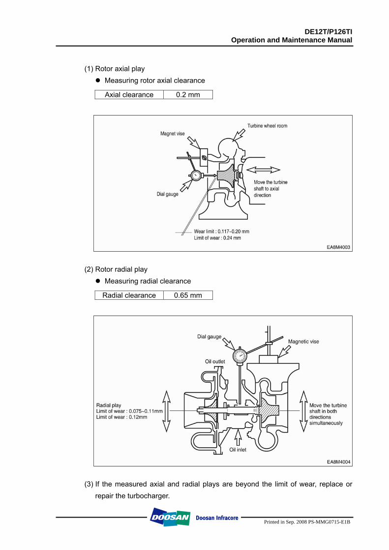
DE12T/P126TI Operation and Maintenance Manual
Printed in Sep. 2008 PS-MMG0715-E1B
(1) Rotor axial play
Measuring rotor axial clearance
Axial clearance 0.2 mm
(2) Rotor radial play
Measuring radial clearance
Radial clearance 0.65 mm
(3) If the measured axial and radial plays are beyond the limit of wear, replace or
repair the turbocharger.
DE12T/P126TI Operation and Maintenance Manual
Printed in Sep. 2008 PS-MMG0715-E1B
3) Guide for disassembling/cleaning and checking the turbocharger
First, disassemble the turbocharger from the engine and clean/check it with the oil inlet and outlet plugged with tape and so on.
4) Precautions for reassembling the tarbocharger onto the engine
For reassembly of the turbocharger or handling it after reassembly operation, be sure to observe the following precautions: Especially, exercise extreme care to prevent foreign matters from entering the inside of the turbocharger.
(1) Lubricating system
Before reassembling the turbocharger onto the engine, inject new oil in the oil inlet port and lubricate the journal and thrust bearings by rotating them with hand .
Clean not only the pipes installed between the engine and oil inlet port but also the oil outlet pipe and check them for damage or foreign matters.
Assemble each joint on oil pipes securely to prevent oil leaks. (2) Intake system
Check the inside of the intake system for foreign matters. Assemble each joint on the intake duct and air cleaner securely to prevent
air leaks. (3) Exhaust system
Check the inside of the exhaust system for foreign matters. Be sure to use heat resisting steel bolts and nuts. Do not interchange them
with ordinary steel bolts and nuts when performing reassembly operation. Apply anti-seizure coating to the bolts and nuts.
Assemble each joint on the exhaust pipes securely to prevent gas leaks
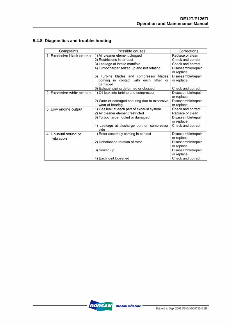
DE12T/P126TI Operation and Maintenance Manual
Printed in Sep. 2008 PS-MMG0715-E1B
5.4.8. Diagnostics and troubleshooting
Complaints Possible causes Corrections 1) Air cleaner element clogged Replace or clean 2) Restrictions in air duct Check and correct 3) Leakage at intake manifold Check and correct 4) Turbocharger seized up and not rotating Disassemble/repair
or replace 5) Turbine blades and compressor blades
coming in contact with each other or damaged
Disassemble/repair or replace
1. Excessive black smoke
6) Exhaust piping deformed or clogged Check and correct 1) Oil leak into turbine and compressor Disassemble/repair
or replace 2. Excessive white smoke
2) Worn or damaged seal ring due to excessive wear of bearing
Disassemble/repair or replace
1) Gas leak at each part of exhaust system Check and correct 2) Air cleaner element restricted Replace or clean 3) Turbocharger fouled or damaged Disassemble/repair
or replace
3. Low engine output
4) Leakage at discharge port on compressor side
Check and correct
1) Rotor assembly coming in contact Disassemble/repair or replace
2) Unbalanced rotation of rotor Disassemble/repair or replace
3) Seized up Disassemble/repair or replace
4. Unusual sound or vibration
4) Each joint loosened Check and correct
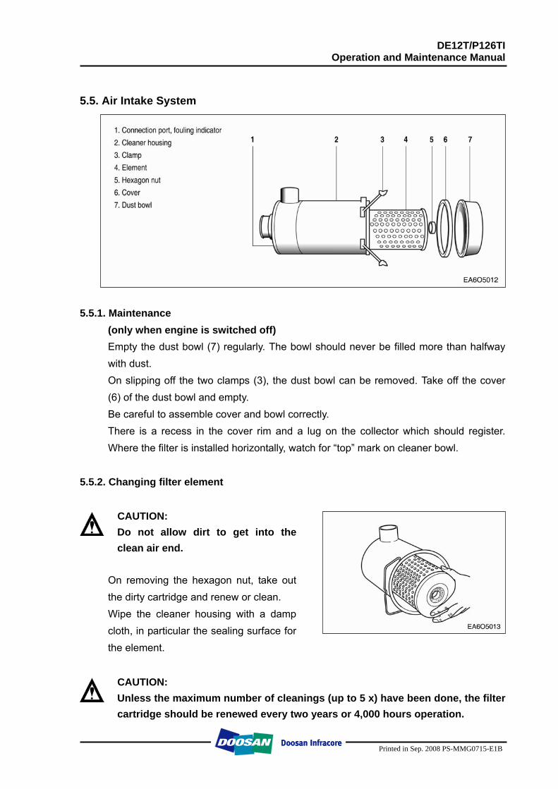
DE12T/P126TI Operation and Maintenance Manual
Printed in Sep. 2008 PS-MMG0715-E1B
5.5. Air Intake System
5.5.1. Maintenance
(only when engine is switched off) Empty the dust bowl (7) regularly. The bowl should never be filled more than halfway with dust. On slipping off the two clamps (3), the dust bowl can be removed. Take off the cover (6) of the dust bowl and empty. Be careful to assemble cover and bowl correctly. There is a recess in the cover rim and a lug on the collector which should register. Where the filter is installed horizontally, watch for “top” mark on cleaner bowl.
5.5.2. Changing filter element
CAUTION: Do not allow dirt to get into the clean air end.
On removing the hexagon nut, take out the dirty cartridge and renew or clean. Wipe the cleaner housing with a damp cloth, in particular the sealing surface for the element.
CAUTION: Unless the maximum number of cleanings (up to 5 x) have been done, the filter cartridge should be renewed every two years or 4,000 hours operation.
M1041A
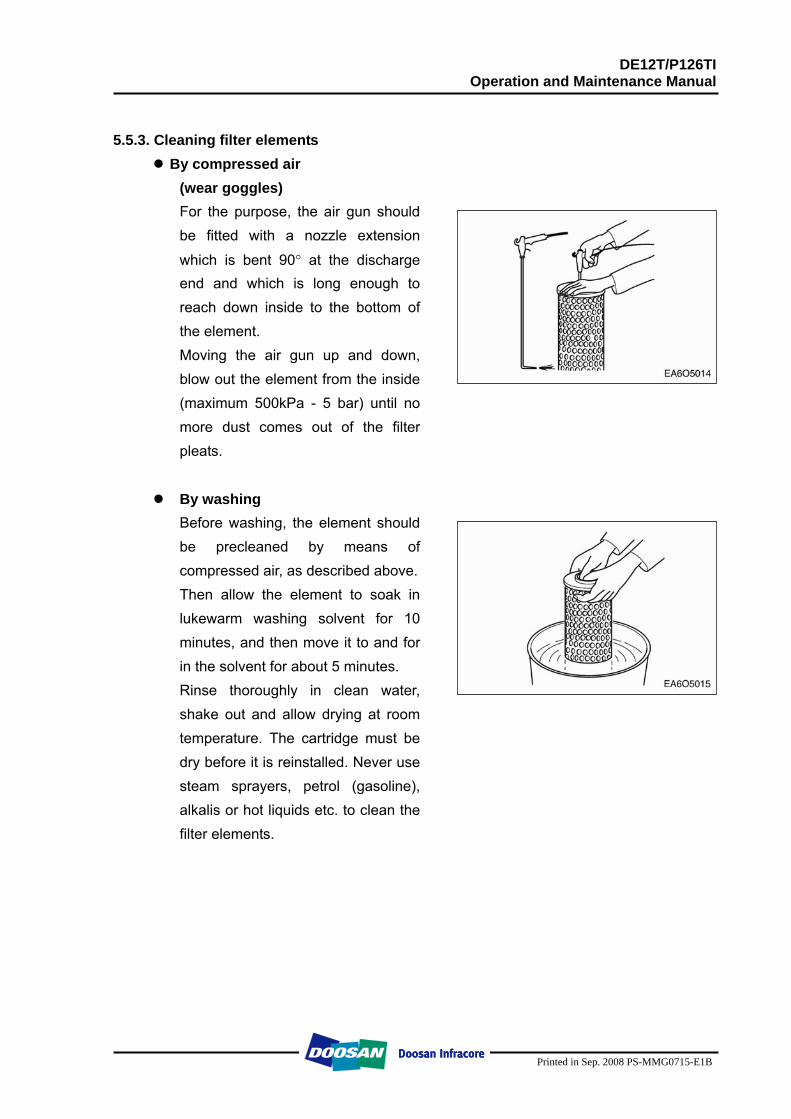
DE12T/P126TI Operation and Maintenance Manual
Printed in Sep. 2008 PS-MMG0715-E1B
5.5.3. Cleaning filter elements
By compressed air (wear goggles) For the purpose, the air gun should be fitted with a nozzle extension
which is bent 90° at the discharge end and which is long enough to reach down inside to the bottom of the element. Moving the air gun up and down, blow out the element from the inside (maximum 500kPa - 5 bar) until no more dust comes out of the filter pleats.
By washing
Before washing, the element should be precleaned by means of compressed air, as described above. Then allow the element to soak in lukewarm washing solvent for 10 minutes, and then move it to and for in the solvent for about 5 minutes. Rinse thoroughly in clean water, shake out and allow drying at room temperature. The cartridge must be dry before it is reinstalled. Never use steam sprayers, petrol (gasoline), alkalis or hot liquids etc. to clean the filter elements.
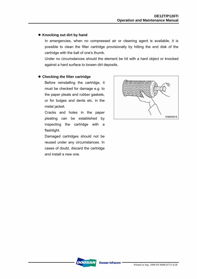
DE12T/P126TI Operation and Maintenance Manual
Printed in Sep. 2008 PS-MMG0715-E1B
Knocking out dirt by hand
In emergencies, when no compressed air or cleaning agent is available, it is possible to clean the filter cartridge provisionally by hitting the end disk of the cartridge with the ball of one's thumb. Under no circumstances should the element be hit with a hard object or knocked against a hard surface to loosen dirt deposits.
Checking the filter cartridge
Before reinstalling the cartridge, it must be checked for damage e.g. to the paper pleats and rubber gaskets, or for bulges and dents etc. in the metal jacket. Cracks and holes in the paper pleating can be established by inspecting the cartridge with a flashlight. Damaged cartridges should not be reused under any circumstances. In cases of doubt, discard the cartridge and install a new one.
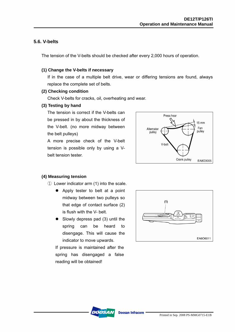
DE12T/P126TI Operation and Maintenance Manual
Printed in Sep. 2008 PS-MMG0715-E1B
5.6. V-belts
The tension of the V-belts should be checked after every 2,000 hours of operation. (1) Change the V-belts if necessary
If in the case of a multiple belt drive, wear or differing tensions are found, always replace the complete set of belts.
(2) Checking condition Check V-belts for cracks, oil, overheating and wear.
(3) Testing by hand The tension is correct if the V-belts can be pressed in by about the thickness of the V-belt. (no more midway between the belt pulleys) A more precise check of the V-belt tension is possible only by using a V-belt tension tester.
(4) Measuring tension
① Lower indicator arm (1) into the scale. Apply tester to belt at a point
midway between two pulleys so that edge of contact surface (2) is flush with the V- belt.
Slowly depress pad (3) until the spring can be heard to disengage. This will cause the indicator to move upwards.
If pressure is maintained after the spring has disengaged a false reading will be obtained!
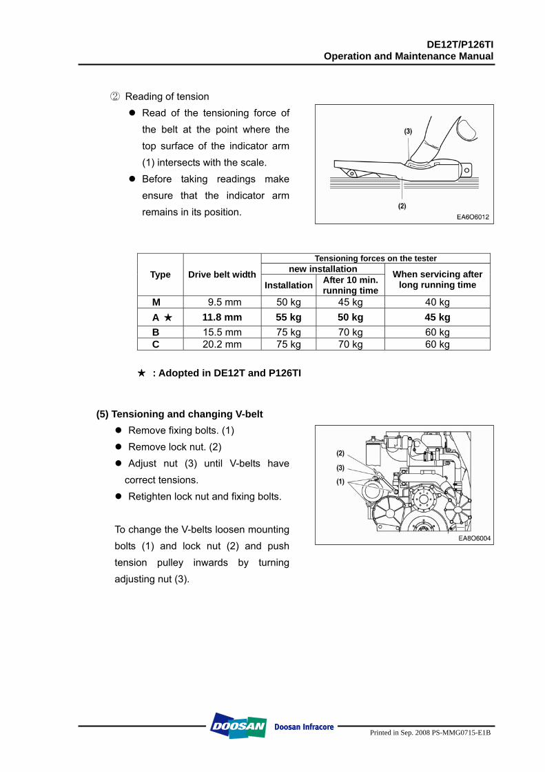
DE12T/P126TI Operation and Maintenance Manual
Printed in Sep. 2008 PS-MMG0715-E1B
② Reading of tension
Read of the tensioning force of the belt at the point where the top surface of the indicator arm (1) intersects with the scale.
Before taking readings make ensure that the indicator arm remains in its position.
Tensioning forces on the tester new installation Type Drive belt width
Installation After 10 min. running time
When servicing after long running time
M 9.5 mm 50 kg 45 kg 40 kg A ★ 11.8 mm 55 kg 50 kg 45 kg B 15.5 mm 75 kg 70 kg 60 kg C 20.2 mm 75 kg 70 kg 60 kg
★ : Adopted in DE12T and P126TI
(5) Tensioning and changing V-belt Remove fixing bolts. (1) Remove lock nut. (2) Adjust nut (3) until V-belts have correct tensions. Retighten lock nut and fixing bolts.
To change the V-belts loosen mounting bolts (1) and lock nut (2) and push tension pulley inwards by turning adjusting nut (3).
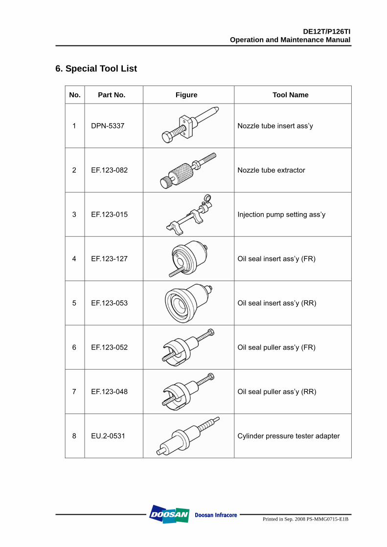
DE12T/P126TI Operation and Maintenance Manual
Printed in Sep. 2008 PS-MMG0715-E1B
6. Special Tool List
No. Part No. Figure Tool Name
1 DPN-5337 Nozzle tube insert ass’y
2 EF.123-082 Nozzle tube extractor
3 EF.123-015 Injection pump setting ass’y
4 EF.123-127 Oil seal insert ass’y (FR)
5 EF.123-053 Oil seal insert ass’y (RR)
6 EF.123-052 Oil seal puller ass’y (FR)
7 EF.123-048 Oil seal puller ass’y (RR)
8 EU.2-0531 Cylinder pressure tester adapter
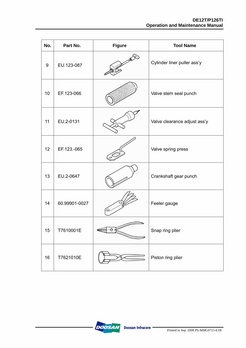
DE12T/P126TI Operation and Maintenance Manual
Printed in Sep. 2008 PS-MMG0715-E1B
No. Part No. Figure Tool Name
9 EU.123-087 Cylinder liner puller ass’y
10 EF.123-066 Valve stem seal punch
11 EU.2-0131 Valve clearance adjust ass’y
12 EF.123.-065 Valve spring press
13 EU.2-0647 Crankshaft gear punch
14 60.99901-0027 Feeler gauge
15 T7610001E Snap ring plier
16 T7621010E Piston ring plier
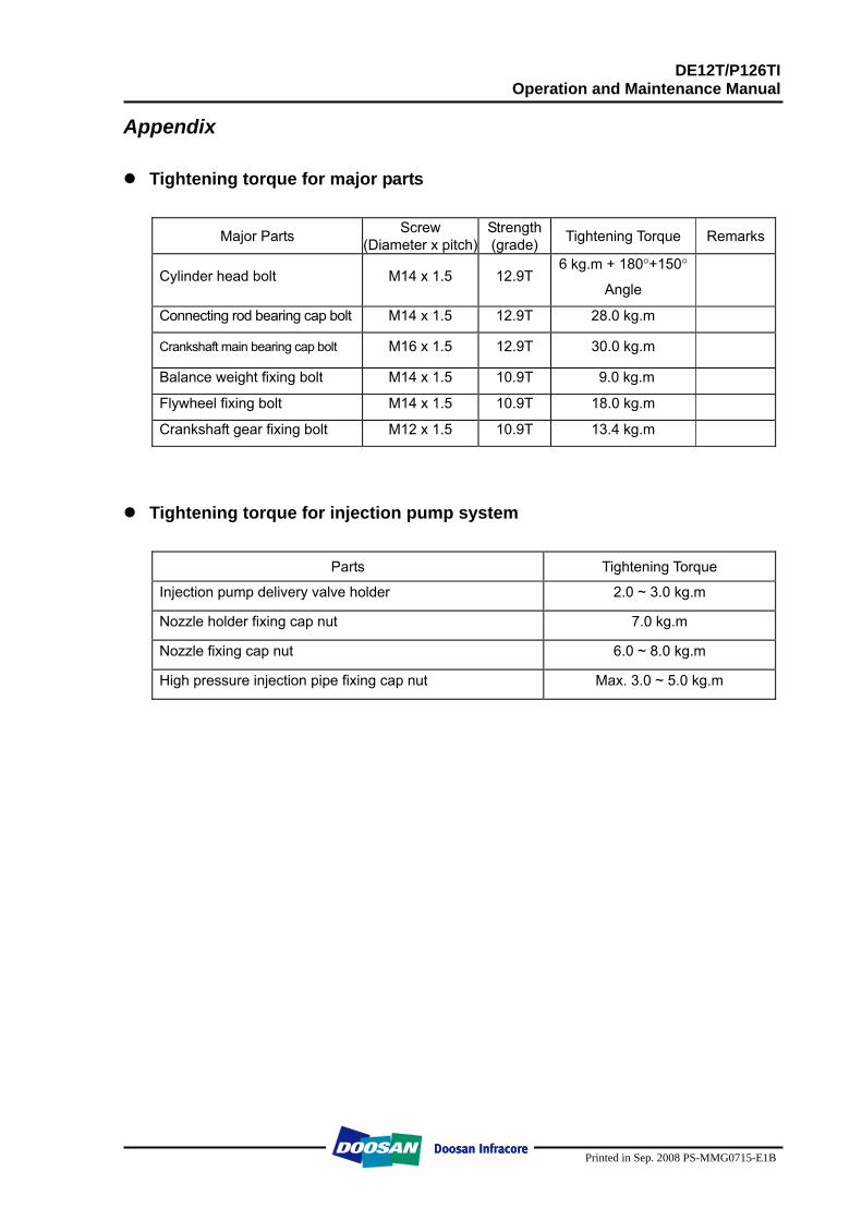
DE12T/P126TI Operation and Maintenance Manual
Printed in Sep. 2008 PS-MMG0715-E1B
Appendix
Tightening torque for major parts
Major Parts Screw (Diameter x pitch)
Strength (grade) Tightening Torque Remarks
Cylinder head bolt M14 x 1.5 12.9T 6 kg.m + 180°+150°
Angle
Connecting rod bearing cap bolt M14 x 1.5 12.9T 28.0 kg.m
Crankshaft main bearing cap bolt M16 x 1.5 12.9T 30.0 kg.m
Balance weight fixing bolt M14 x 1.5 10.9T 9.0 kg.m
Flywheel fixing bolt M14 x 1.5 10.9T 18.0 kg.m
Crankshaft gear fixing bolt M12 x 1.5 10.9T 13.4 kg.m
Tightening torque for injection pump system
Parts Tightening Torque
Injection pump delivery valve holder 2.0 ~ 3.0 kg.m
Nozzle holder fixing cap nut 7.0 kg.m
Nozzle fixing cap nut 6.0 ~ 8.0 kg.m
High pressure injection pipe fixing cap nut Max. 3.0 ~ 5.0 kg.m
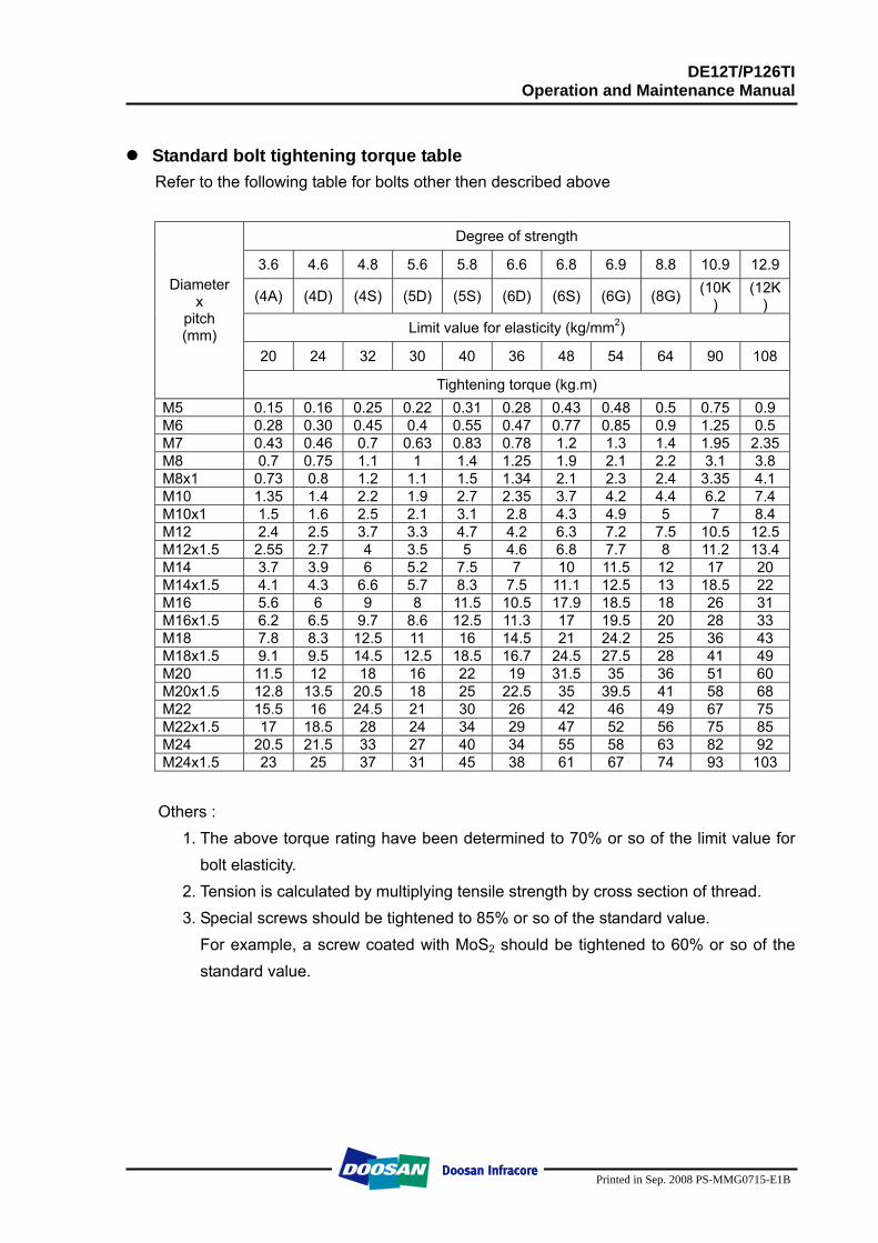
DE12T/P126TI Operation and Maintenance Manual
Printed in Sep. 2008 PS-MMG0715-E1B
Standard bolt tightening torque table Refer to the following table for bolts other then described above
Degree of strength
3.6 4.6 4.8 5.6 5.8 6.6 6.8 6.9 8.8 10.9 12.9
(4A) (4D) (4S) (5D) (5S) (6D) (6S) (6G) (8G) (10K)
(12K)
Limit value for elasticity (kg/mm2)
20 24 32 30 40 36 48 54 64 90 108
Diameter x
pitch (mm)
Tightening torque (kg.m) M5 0.15 0.16 0.25 0.22 0.31 0.28 0.43 0.48 0.5 0.75 0.9 M6 0.28 0.30 0.45 0.4 0.55 0.47 0.77 0.85 0.9 1.25 0.5 M7 0.43 0.46 0.7 0.63 0.83 0.78 1.2 1.3 1.4 1.95 2.35 M8 0.7 0.75 1.1 1 1.4 1.25 1.9 2.1 2.2 3.1 3.8 M8x1 0.73 0.8 1.2 1.1 1.5 1.34 2.1 2.3 2.4 3.35 4.1 M10 1.35 1.4 2.2 1.9 2.7 2.35 3.7 4.2 4.4 6.2 7.4 M10x1 1.5 1.6 2.5 2.1 3.1 2.8 4.3 4.9 5 7 8.4 M12 2.4 2.5 3.7 3.3 4.7 4.2 6.3 7.2 7.5 10.5 12.5 M12x1.5 2.55 2.7 4 3.5 5 4.6 6.8 7.7 8 11.2 13.4 M14 3.7 3.9 6 5.2 7.5 7 10 11.5 12 17 20 M14x1.5 4.1 4.3 6.6 5.7 8.3 7.5 11.1 12.5 13 18.5 22 M16 5.6 6 9 8 11.5 10.5 17.9 18.5 18 26 31 M16x1.5 6.2 6.5 9.7 8.6 12.5 11.3 17 19.5 20 28 33 M18 7.8 8.3 12.5 11 16 14.5 21 24.2 25 36 43 M18x1.5 9.1 9.5 14.5 12.5 18.5 16.7 24.5 27.5 28 41 49 M20 11.5 12 18 16 22 19 31.5 35 36 51 60 M20x1.5 12.8 13.5 20.5 18 25 22.5 35 39.5 41 58 68 M22 15.5 16 24.5 21 30 26 42 46 49 67 75 M22x1.5 17 18.5 28 24 34 29 47 52 56 75 85 M24 20.5 21.5 33 27 40 34 55 58 63 82 92 M24x1.5 23 25 37 31 45 38 61 67 74 93 103
Others :
1. The above torque rating have been determined to 70% or so of the limit value for bolt elasticity.
2. Tension is calculated by multiplying tensile strength by cross section of thread. 3. Special screws should be tightened to 85% or so of the standard value.
For example, a screw coated with MoS2 should be tightened to 60% or so of the standard value.
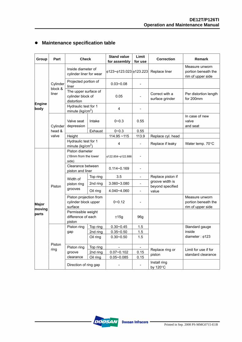
DE12T/P126TI Operation and Maintenance Manual
Printed in Sep. 2008 PS-MMG0715-E1B
Maintenance specification table
Group Part Check Stand value for assembly
Limit for use Correction Remark
Inside diameter of cylinder liner for wear
φ123~φ123.023 φ123.223 Replace liner Measure unworn portion beneath the rim of upper side
Projected portion of liner
0.03~0.08 -
The upper surface of cylinder block of distortion
0.05 - Correct with a surface grinder
Per distortion length for 200mm
Cylinder block & liner
Hydraulic test for 1 minute (kg/cm2)
4 -
Intake 0~0.3 0.55 In case of new valve and seat
Valve seat depression
Exhaust 0~0.3 0.55 Height 114.95 ~115 113.9 Replace cyl. head
Engine body
Cylinder head & valve
Hydraulic test for 1 minute (kg/cm2)
4 - Replace if leaky Water temp. 70°C
Piston diameter (18mm from the lower side)
φ122.854~φ122.886 -
Clearance between piston and liner
0.114~0.169 -
Top ring 3.5 -
2nd ring 3.060~3.080 - Width of piston ring grooves Oil ring 4.040~4.060 -
Replace piston if groove width is beyond specified value
Piston projection from cylinder block upper surface
0~0.12 - Measure unworn portion beneath the rim of upper side
Piston
Permissible weight difference of each piston
±15g 96g
Top ring 0.30~0.45 1.5 2nd ring 0.35~0.50 1.5
Piston ring gap
Oil ring 0.30~0.50 1.5
Standard gauge inside diameter : φ123
Top ring - - 2nd ring 0.07~0.102 0.15
Piston ring groove clearance Oil ring 0.05~0.085 0.15
Replace ring or piston
Limit for use if for standard clearance
Major moving parts
Piston ring
Direction of ring gap - - Install ring by 120°C
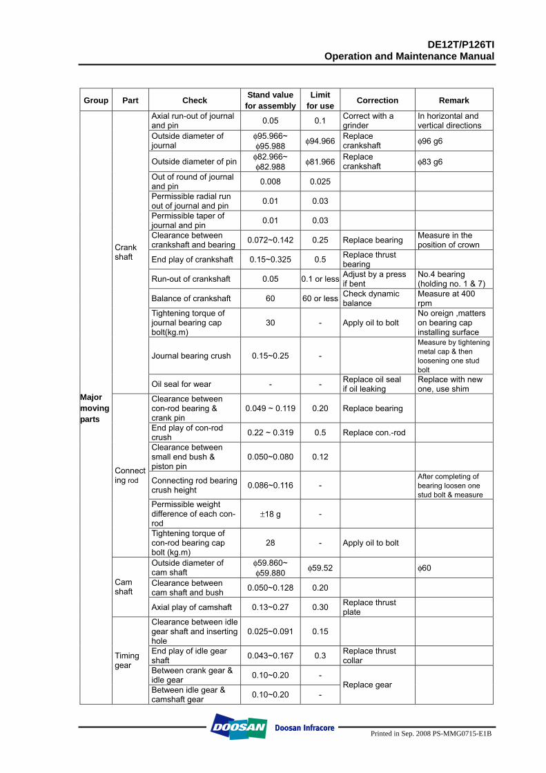
DE12T/P126TI Operation and Maintenance Manual
Printed in Sep. 2008 PS-MMG0715-E1B
Group Part Check Stand value for assembly
Limit for use Correction Remark
Axial run-out of journal and pin 0.05 0.1 Correct with a
grinder In horizontal and vertical directions
Outside diameter of journal
φ95.966~ φ95.988 φ94.966 Replace
crankshaft φ96 g6
Outside diameter of pin φ82.966~ φ82.988 φ81.966 Replace
crankshaft φ83 g6
Out of round of journal and pin 0.008 0.025
Permissible radial run out of journal and pin 0.01 0.03
Permissible taper of journal and pin 0.01 0.03
Clearance between crankshaft and bearing 0.072~0.142 0.25 Replace bearing Measure in the
position of crown
End play of crankshaft 0.15~0.325 0.5 Replace thrust bearing
Run-out of crankshaft 0.05 0.1 or less Adjust by a press if bent
No.4 bearing (holding no. 1 & 7)
Balance of crankshaft 60 60 or less Check dynamic balance
Measure at 400 rpm
Tightening torque of journal bearing cap bolt(kg.m)
30 - Apply oil to bolt No oreign ,matters on bearing cap installing surface
Journal bearing crush 0.15~0.25 -
Measure by tightening metal cap & then loosening one stud bolt
Crank shaft
Oil seal for wear - - Replace oil seal if oil leaking
Replace with new one, use shim
Clearance between con-rod bearing & crank pin
0.049 ~ 0.119 0.20 Replace bearing
End play of con-rod crush 0.22 ~ 0.319 0.5 Replace con.-rod
Clearance between small end bush & piston pin
0.050~0.080 0.12
Connecting rod bearing crush height 0.086~0.116 -
After completing of bearing loosen one stud bolt & measure
Permissible weight difference of each con-rod
±18 g -
Connecting rod
Tightening torque of con-rod bearing cap bolt (kg.m)
28 - Apply oil to bolt
Outside diameter of cam shaft
φ59.860~ φ59.880 φ59.52 φ60
Clearance between cam shaft and bush 0.050~0.128 0.20
Cam shaft
Axial play of camshaft 0.13~0.27 0.30 Replace thrust plate
Clearance between idle gear shaft and inserting hole
0.025~0.091 0.15
End play of idle gear shaft 0.043~0.167 0.3 Replace thrust
collar
Between crank gear & idle gear 0.10~0.20 -
Major movingparts
Timing gear
Between idle gear & camshaft gear 0.10~0.20 -
Replace gear
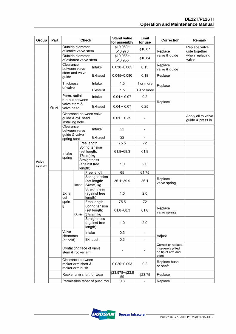
DE12T/P126TI Operation and Maintenance Manual
Printed in Sep. 2008 PS-MMG0715-E1B
Group Part Check Stand value
for assemblyLimit
for use Correction Remark
Outside diameter of intake valve stem
φ10.950~ φ10.970 φ10.87
Outside diameter of exhaust valve stem
φ10.935~ φ10.955 φ10.84
Replace valve & guide
Replace valve uide together when replacing valve
Intake 0.030~0.065 0.15 Replace valve & guide
Clearance between valve stem and valve guide Exhaust 0.045~0.080 0.18 Replace
Intake 1.5 1 or more Thickness of valve
Exhaust 1.5 0.9 or moreReplace
Intake 0.04 ~ 0.07 0.2 Perm. radial run-out between valve stem & valve head Exhaust 0.04 ~ 0.07 0.25
Replace
Clearance between valve guide & cyl. head installing hole
0.01 ~ 0.39 - Apply oil to valve guide & press in
Intake 22 - Clearance between valve guide & valve spring seat Exhaust 22 -
Free length 75.5 72 Spring tension (set length: 37mm) kg
61.8~68.3 61.8
Valve
Intake spring
Straightness (against free length)
1.0 2.0
Free length 65 61.75 Spring tension (set length: 34mm) kg
36.1~39.9 36.1 Replace valve spring
Inner Straightness (against free length)
1.0 2.0
Free length 75.5 72 Spring tension (set length: 37mm) kg
61.8~68.3 61.8 Replace valve spring
Exhaust spring
Outer Straightness (against free length)
1.0 2.0
Intake 0.3 - Valve clearance (at cold) Exhaust 0.3 -
Adjust
Contacting face of valve stem & rocker arm - -
Correct or replace if severely pitted on tip of arm and stem
Clearance between rocker arm shaft & rocker arm bush
0.020~0.093 0.2 Replace bush or shaft
Rocker arm shaft for wear φ23.978~φ23.959 φ23.75 Replace
Valve system
Permissible taper of push rod 0.3 - Replace
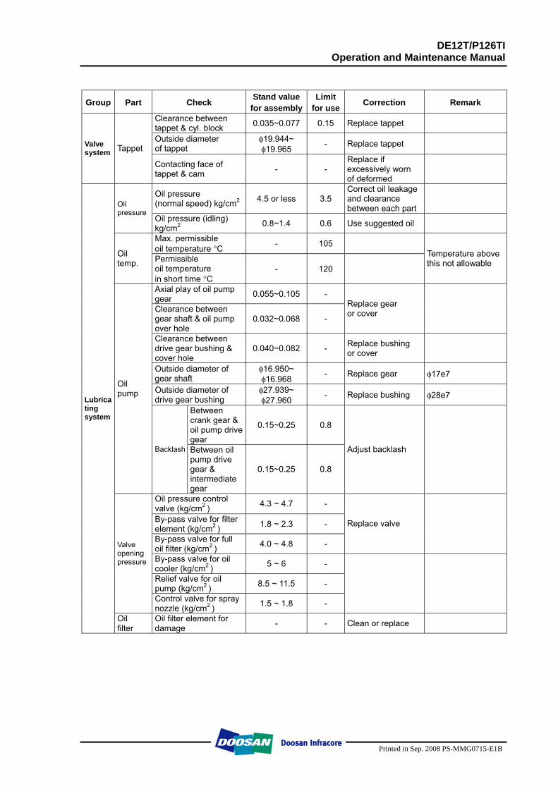
DE12T/P126TI Operation and Maintenance Manual
Printed in Sep. 2008 PS-MMG0715-E1B
Group Part Check Stand value for assembly
Limit for use Correction Remark
Clearance between tappet & cyl. block 0.035~0.077 0.15 Replace tappet
Outside diameter of tappet
φ19.944~ φ19.965 - Replace tappet Valve
system Tappet
Contacting face of tappet & cam - -
Replace if excessively worn of deformed
Oil pressure (normal speed) kg/cm2 4.5 or less 3.5
Correct oil leakage and clearance between each part
Oil pressure
Oil pressure (idling) kg/cm2 0.8~1.4 0.6 Use suggested oil
Max. permissible oil temperature °C - 105
Oil temp. Permissible
oil temperature in short time °C
- 120
Temperature above this not allowable
Axial play of oil pump gear 0.055~0.105 -
Clearance between gear shaft & oil pump over hole
0.032~0.068 -
Replace gear or cover
Clearance between drive gear bushing & cover hole
0.040~0.082 - Replace bushing or cover
Outside diameter of gear shaft
φ16.950~ φ16.968 - Replace gear φ17e7
Outside diameter of drive gear bushing
φ27.939~ φ27.960 - Replace bushing φ28e7
Between crank gear & oil pump drive gear
0.15~0.25 0.8
Oil pump
Backlash Between oil pump drive gear & intermediate gear
0.15~0.25 0.8
Adjust backlash
Oil pressure control valve (kg/cm2 ) 4.3 ~ 4.7 -
By-pass valve for filter element (kg/cm2 ) 1.8 ~ 2.3 -
By-pass valve for full oil filter (kg/cm2 ) 4.0 ~ 4.8 -
Replace valve
By-pass valve for oil cooler (kg/cm2 ) 5 ~ 6 -
Relief valve for oil pump (kg/cm2 ) 8.5 ~ 11.5 -
Valve opening pressure
Control valve for spray nozzle (kg/cm2 ) 1.5 ~ 1.8 -
Lubricating system
Oil filter
Oil filter element for damage - - Clean or replace
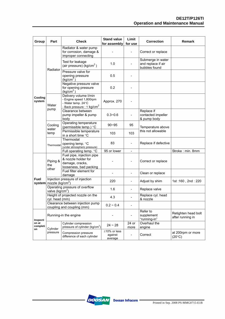
DE12T/P126TI Operation and Maintenance Manual
Printed in Sep. 2008 PS-MMG0715-E1B
Group Part Check Stand valuefor assembly
Limit for use Correction Remark
Radiator & water pump for corrosion, damage & improper connecting
- - Correct or replace
Test for leakage (air pressure) (kg/cm2 ) 1.0 -
Submerge in water and replace if air bubbles found
Pressure valve for opening pressure (kg/cm2 )
0.5 -
Radiator
Negative pressure valve for opening pressure (kg/cm2 )
0.2 -
Delivery volume l/min - Engine speed 1,800rpm - Water temp. 24°C - Back pressure : 1 kg/cm2
Approx. 270 - Water pump Clearance between
pump impeller & pump body
0.3~0.6 - Replace if contacted impeller & pump body
Operating temperature (permissible temp.) °C 90~95 95 Cooling
water temp Permissible temperature
in a short time °C 103 103
Temperature above this not allowable
Thermostat opening temp. °C (under atmospheric pressure)
83 - Replace if defective
Cooling system
Thermostat
Full operating temp. °C 95 or lower - Stroke : min. 8mm Fuel pipe, injection pipe & nozzle holder for damage, cracks, looseness, bad packing
- - Correct or replace Piping & the other Fuel filter element for
damage - - Clean or replace
Injection pressure of injection nozzle (kg/cm2) 220 - Adjust by shim 1st :160 , 2nd : 220
Operating pressure of overflow valve (kg/cm2) 1.6 - Replace valve
Height of projected nozzle on the cyl. head (mm) 4.3 - Replace cyl. head
& nozzle
Fuel system
Clearance between injection pump coupling and coupling (mm) 0.2 ~ 0.4 -
Running-in the engine - - Refer to supplement “running-in”
Retighten head bolt after running in
Cylinder compression pressure of cylinder (kg/cm2) 24 ~ 28 24 or
more Overhaul the engine
Inspection at completion Cylinder
pressure Compression pressure difference of each cylinder
±10% or less against average
- Correct at 200rpm or more (20°C)