Embed Size (px)
Citation preview

78
9
0
45
612
3
CALL
Z
A
78
9
0
45
612
3
CALL
Z
A
SYSTEM A
Control Box
1830 Series VoIP / RS-232 Control Box
The VoIP/RS-232 Control Box is fee based and operates on DoorKing’s network website. The control box provides voice communication and data communication plan selected at DoorKing’s Server website.
The VoIP/RS-232 Control Box is designed to be used with: 1833, 1834, 1835, 1837, and 1838 entry systems.
The VoIP/RS-232 control box MUST be wired to the telephone entry system’s phone line (voice) and RS 232 connection (data). See page 2.
The VoIP/RS-232 control box will work with TWO 1830 entry systems connected to it. These are designated as System A and System B. See next page to wire 1 or 2 1830 entry systems to the box.
DoorKing Part Number
2334-080
Copyright 2020 DoorKing®, Inc. All rights reserved.
120 S. Glasgow AvenueInglewood, California 90301 U.S.A.
Installation Steps:1. Install and wire control box to 1830(s) and your router (page 2).
2. Power up control box (page 2).
3. Register control box and System A 1830 online (see above).
4. Setup Phone Number/Data over IP on 1830(s) system(s) (page 3).
5. Test control box (page 4).
6. Troubleshoot control box if necessary (page 4).
Note: Installation steps assume that the 1830 system has already been setup for the master code (section 3.2.1 in manual) and multiple system programming (section 3.2.9 (*04) in manual)if 2 1830s are being used.
Destructive Attack: Level I Line Security: Level I Endurance: Level IV Standby Power: Level ISingle Point Locking Device: Level I
DO NOT use this VoIP deviceto make 911 calls.
Installation Options:
500 Ft MaxPhone Line and RS-232
Box Installed at RouterYour Router
325 Ft MaxEthernet Line - Cat5
Box Installed at Phone Entry System
Your RouterRegistrationThe VoIP adapter and DKS TCP/IP adapter WILL NOT function until registered with the DoorKing VoIP/Data server.The registration page may be reached at:https://dksdb.dksoftware.com/UserLogin.aspx
NOTE: Your router MUST be connected to the internet.
78
9
0
45
612
3
CALL
Z
A
Before starting the registration process, be sure to have the VoIP ID number written down. This number is printed on a label on the VoIP adapter. Also the Master Code of the phone entry system will be needed for the registration process.
Click the IM/VoIP DKS button on the first screen. Enter your personal information, then click the entry systems tab. Add an entry system by selecting the DKS VoIP/Data service.
NOTE: VoIP/Data uses the VoIP adapter AND the DoorKing client mode DKS TCP/IP adapter. (DO NOT select the DKS VoIP only. This is for voice ONLY and data will not function with this selection.)
Enter the VoIP ID number on the decal on VoIP adapter, the optional name of the system A entry system if desired, and your postal area code which will be used for control box phone number selection. Finally, enter the Master Code of the System A entry system, then Click ADD. The entry system will be added to the table above. Click the billing tab and enter billing information. When completed, the VoIP and DKS TCP/IP adapters will be turned ON and a phone number will be automatically assigned to the control box.
Record the phone number assigned to the control box for your records and also needed when programming the 1830 on page 3.
IMPORTANT: The 1830 circuit board MUST be Revision “Z” or higher to work.
1
2334-065-G-10-20

PH LINE
16VAC16VACE GND
POWER
PH LINE
DATA OUT
BUSY OUTBUSY INGROUND
DATA IN
PH LINEPH LINE
DATA OUT
BUSY OUTBUSY INGROUND
DATA IN
RESET LINKS
SW3
CHRG
PHONERJ11
Cat5 Cat5 Cat5
VOIP
BATTBATTERY
DATA
P1 P2 P3
1
ON
2
LINK
VoIP
Ana
log
Tele
phon
e Ada
pter
STATUS
LNK/ACTRING 2
RING 1
RESET 12 VDCPHONE LINE
PC LAN
VoIP
ID N
umbe
r
RS 232
RS 232
2334-010
TCP/IPDKS
NCNORING
HF
1816
HS
ON
SPKVOLFEED
BACK
RS 232
ELEVATOR
OFFKEYPAD
3 2 1
3
321
MASTERCODE
16AC16ACBAT1NO1NC1C2RY2CAZIMC5VDCIMDSPKRCOMMICPSWCGNDPHONE
1
2
3
12
34
56
78
910
1112
1314
123456
NCNORING
HF
1816
HS
ON
SPKVOLFEED
BACK
RS 232
ELEVATOR
MICVOL
OFFKEYPAD
3 2 1
3 2 1
321
MASTERCODE
16AC16ACBAT1NO1NC1C2RY2CAZIMC5VDCIMDSPKRCOMMICPSWCGNDPHONE
1
2
3
12
34
56
78
910
1112
1314
123456
16.5VAC40 VA16.5VAC
20 VA
16.5VAC20 VA
16.5VAC20 VA
AuxTerminal
SYSTEM A1830
Voice/Data systemshould be as close as
possible to SYSTEM A.
SYSTEM BOptional 1830
Main Terminal
Twisted PairMUST be used.
Twisted Pair Phone
Line MUST be used.
Choose How to Power VoIP/RS-232 Board:1 Wire supplied power transformer (16.5 VAC, 40 VA) to Aux terminal 1 & 2, wire VoIP/RS-232 power terminal to Aux terminal5 & 6. This powers VoIP/RS-232 board AND DoorKing phone entry system’s Aux terminal. If Aux terminal 1 & 2 is already being powered by a 16.5 VAC, 20 VA transformer, REPLACE IT with the16.5 VAC, 40 VA transformer that is supplied to power BOTH devices.NOT available on the 1834.
2 Wire supplied power transformer (16.5 VAC, 40 VA) DIRECTLYto VoIP/RS-232 power terminal. DO NOT wire to Aux terminal 5 & 6.
18 AWG Min. Power Wire
500
ft RS
-232
MAX
500
ft RS
-232
MAX
Cat5 Cable
DATA OUT-RedDATA IN-Black
BUSY OUT-WhiteBUSY IN-BrownGROUND-Green
RS 232 Connection
12345
System ATerminal
1830Terminal
Existing Power
ExistingPower
Supplied PowerTransformer
Supplied PowerTransformer
5 & 6
1 &
2
EarthGround
Data
Voice
Voice
Data
AFTER DKS Online Registration Completed,VoIP/RS-232 Board will function.
See previous page.
Wiring
Box Installation
The plastic enclosure comes with mounting
brackets and hardware to mount on enclosure. Mount enclosure on
surface using appropriate hardware (not included). IT IS NOT RECOMMENDED DRILLING
HOLES IN THE PLASTIC ENCLOSURE!If holes must be drilled, remove the circuit board before drilling and be sure that mounting bolts/screws do not touch the back of the circuit board. Holes must be sealed to prevent water intrusion.
Mounting Bracket
and Hardware
Reset Timer Selector
Reset VoIP
Reset Links
Cat5 cable to Your Routerconnected to the internet
See previous page.
OFF-OFF = No resetOFF-ON = 1 dayON-OFF = 2 daysON-ON = 3 days
TWO Entry Systems - The Voice/Data system can supply telephone service and programming for TWO 1830s designated as System A and System B. The telephone line is SHARED with both 1830s. Each 1830 MUST be programmed for Multiple Systems, see specific 1830 Installation/Owner’s instruction manual for more information.
RS 232
RS 232
RS-232“A”
Do NotUse Line
Do NotUse PC
DKS TCP/IPAdapter
DCPower
RS-232“B”
The EARTH GROUND must be connected to a proper ground close by (ground rod, cold water pipe in the ground, existing electrical ground, etc).
1816
JumperMUST beMoved
1816
JumperMUST beMoved
Do Not ConnectPower To AReceptacle
Controlled ByA ON/OFF Switch.
System B Phone Line Alternate Use - If system B is not being used for a second phone entry system, a phone can be installed and used. It shares the phone line with the System A phone entry system. The phone cannot be used while a transaction is taking place on System A.
1
1
16.5VAC40 VA
2
- OR -
ONLY
ONLY
ONLY
DATA OUT-RedDATA IN-Black
BUSY OUT-WhiteBUSY IN-BrownGROUND-Green
RS 232 Connection
12345
System BTerminal
1830Terminal
Mounting
Bracket
and
Hardware
Wire Run
Wire Run
VoIP Adapter
TCP/IP Camera
Battery Back-UpCall DoorKing
2
2334-065-G-10-20
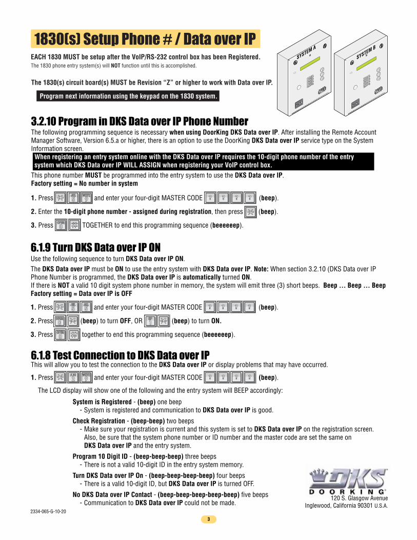
1830(s) Setup Phone # / Data over IP
The 1830(s) circuit board(s) MUST be Revision “Z” or higher to work with Data over IP.
Program next information using the keypad on the 1830 system.
EACH 1830 MUST be setup after the VoIP/RS-232 control box has been Registered.The 1830 phone entry system(s) will NOT function until this is accomplished.
120 S. Glasgow AvenueInglewood, California 90301 U.S.A.
78
9
0
45
612
3
CALL
Z
A
78
9
0
45
612
3
CALL
Z
A
SYSTEM A
SYSTEM B
1. Press and enter your four-digit MASTER CODE (beep).
2. Enter the 10-digit phone number - assigned during registration, then press (beep).
3. Press TOGETHER to end this programming sequence (beeeeeep).
The following programming sequence is necessary when using DoorKing DKS Data over IP. After installing the Remote Account Manager Software, Version 6.5.a or higher, there is an option to use the DoorKing DKS Data over IP service type on the System Information screen. When registering an entry system online with the DKS Data over IP requires the 10-digit phone number of the entry system which DKS Data over IP WILL ASSIGN when registering your VoIP control box.This phone number MUST be programmed into the entry system to use the DKS Data over IP.Factory setting = No number in system
3.2.10 Program in DKS Data over IP Phone Number
?? ?? ?? ??99WXYZWXYZ
55JKLJKL
00OPEROPER
Use the following sequence to turn DKS Data over IP ON.The DKS Data over IP must be ON to use the entry system with DKS Data over IP. Note: When section 3.2.10 (DKS Data over IP Phone Number is programmed, the DKS Data over IP is automatically turned ON.If there is NOT a valid 10 digit system phone number in memory, the system will emit three (3) short beeps. Beep ... Beep ... BeepFactory setting = Data over IP is OFF
6.1.9 Turn DKS Data over IP ON
1. Press and enter your four-digit MASTER CODE (beep).
2. Press (beep) to turn OFF, OR (beep) to turn ON.
3. Press together to end this programming sequence (beeeeeep).
?? ?? ?? ??55JKLJKL
55JKLJKL
00OPEROPER
11SPSP
00OPEROPER
1. Press and enter your four-digit MASTER CODE (beep).
The LCD display will show one of the following and the entry system will BEEP accordingly:
?? ?? ?? ??99WXYZWXYZ
22ABCABC
6.1.8 Test Connection to DKS Data over IPThis will allow you to test the connection to the DKS Data over IP or display problems that may have occurred.
System is Registered - (beep) one beep - System is registered and communication to DKS Data over IP is good.
Check Registration - (beep-beep) two beeps - Make sure your registration is current and this system is set to DKS Data over IP on the registration screen. Also, be sure that the system phone number or ID number and the master code are set the same on DKS Data over IP and the entry system.
Program 10 Digit ID - (beep-beep-beep) three beeps - There is not a valid 10-digit ID in the entry system memory.
Turn DKS Data over IP On - (beep-beep-beep-beep) four beeps - There is a valid 10-digit ID, but DKS Data over IP is turned OFF.
No DKS Data over IP Contact - (beep-beep-beep-beep-beep) five beeps - Communication to DKS Data over IP could not be made.
3
2334-065-G-10-20
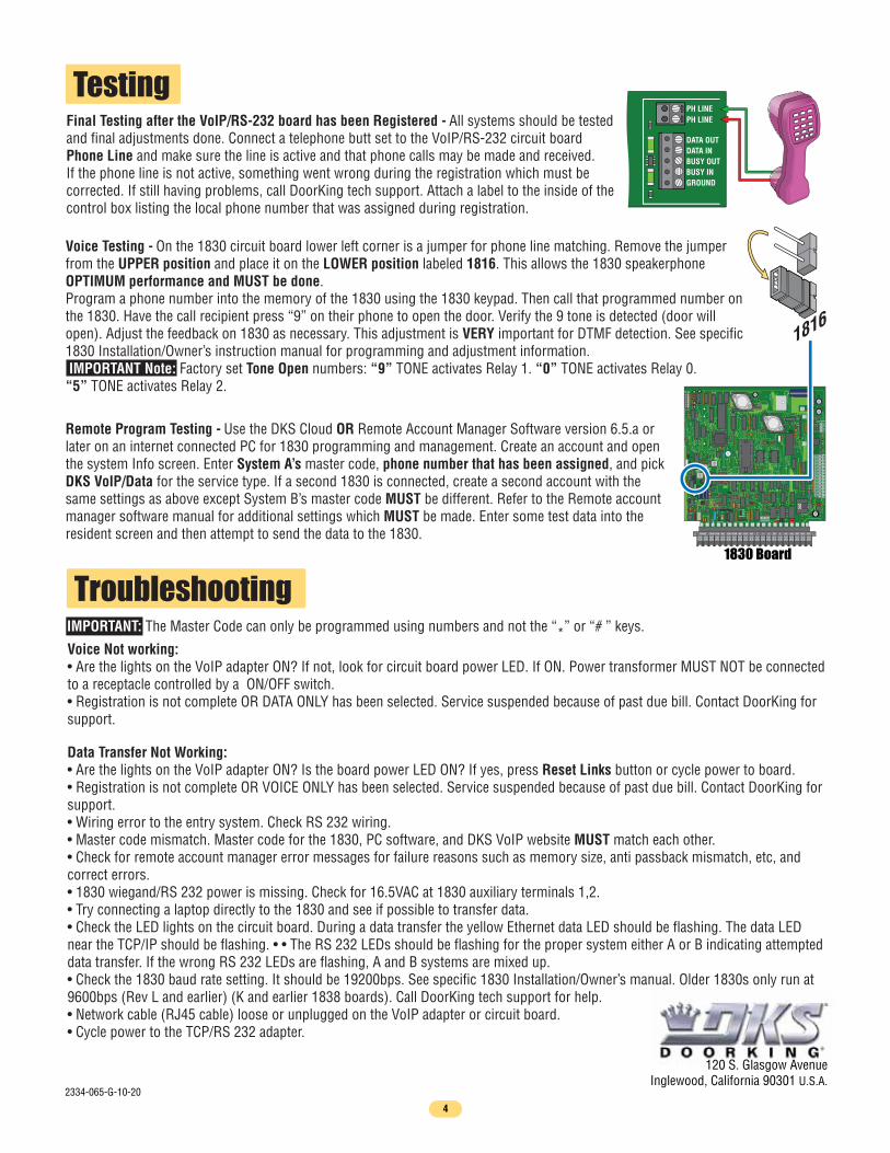
Voice Testing - On the 1830 circuit board lower left corner is a jumper for phone line matching. Remove the jumper from the UPPER position and place it on the LOWER position labeled 1816. This allows the 1830 speakerphone OPTIMUM performance and MUST be done.Program a phone number into the memory of the 1830 using the 1830 keypad. Then call that programmed number on the 1830. Have the call recipient press “9” on their phone to open the door. Verify the 9 tone is detected (door will open). Adjust the feedback on 1830 as necessary. This adjustment is VERY important for DTMF detection. See specific 1830 Installation/Owner’s instruction manual for programming and adjustment information.IMPORTANT Note: Factory set Tone Open numbers: “9” TONE activates Relay 1. “0” TONE activates Relay 0.“5” TONE activates Relay 2.
Remote Program Testing - Use the DKS Cloud OR Remote Account Manager Software version 6.5.a or later on an internet connected PC for 1830 programming and management. Create an account and open the system Info screen. Enter System A’s master code, phone number that has been assigned, and pick DKS VoIP/Data for the service type. If a second 1830 is connected, create a second account with the same settings as above except System B’s master code MUST be different. Refer to the Remote account manager software manual for additional settings which MUST be made. Enter some test data into the resident screen and then attempt to send the data to the 1830.
TestingFinal Testing after the VoIP/RS-232 board has been Registered - All systems should be tested and final adjustments done. Connect a telephone butt set to the VoIP/RS-232 circuit board Phone Line and make sure the line is active and that phone calls may be made and received. If the phone line is not active, something went wrong during the registration which must be corrected. If still having problems, call DoorKing tech support. Attach a label to the inside of the control box listing the local phone number that was assigned during registration.
1816
PH LINEPH LINE
DATA OUT
BUSY OUTBUSY INGROUND
DATA IN
TroubleshootingIMPORTANT: The Master Code can only be programmed using numbers and not the “*” or “# ” keys.
120 S. Glasgow AvenueInglewood, California 90301 U.S.A.
NCNORING
HF
1816
HS
ON
SPKVOLFEED
BACK
RS 232
ELEVATOR
MICVOL
OFFKEYPAD
3 2 1
3 2 1
321
MASTERCODE
16AC16ACBAT1NO1NC1C2RY2CAZIMC5VDCIMDSPKRCOMMICPSWCGNDPHONE
1
2
3
12
34
56
78
910
1112
1314
123456
1830 Board
Voice Not working:• Are the lights on the VoIP adapter ON? If not, look for circuit board power LED. If ON. Power transformer MUST NOT be connected to a receptacle controlled by a ON/OFF switch.• Registration is not complete OR DATA ONLY has been selected. Service suspended because of past due bill. Contact DoorKing for support.
Data Transfer Not Working: • Are the lights on the VoIP adapter ON? Is the board power LED ON? If yes, press Reset Links button or cycle power to board.• Registration is not complete OR VOICE ONLY has been selected. Service suspended because of past due bill. Contact DoorKing for support.• Wiring error to the entry system. Check RS 232 wiring.• Master code mismatch. Master code for the 1830, PC software, and DKS VoIP website MUST match each other.• Check for remote account manager error messages for failure reasons such as memory size, anti passback mismatch, etc, and correct errors.• 1830 wiegand/RS 232 power is missing. Check for 16.5VAC at 1830 auxiliary terminals 1,2. • Try connecting a laptop directly to the 1830 and see if possible to transfer data.• Check the LED lights on the circuit board. During a data transfer the yellow Ethernet data LED should be flashing. The data LED near the TCP/IP should be flashing. • • The RS 232 LEDs should be flashing for the proper system either A or B indicating attempted data transfer. If the wrong RS 232 LEDs are flashing, A and B systems are mixed up.• Check the 1830 baud rate setting. It should be 19200bps. See specific 1830 Installation/Owner’s manual. Older 1830s only run at 9600bps (Rev L and earlier) (K and earlier 1838 boards). Call DoorKing tech support for help.• Network cable (RJ45 cable) loose or unplugged on the VoIP adapter or circuit board.• Cycle power to the TCP/RS 232 adapter.
4
2334-065-G-10-20