Embed Size (px)
Citation preview

Electrical operating instructions
Door control panel TS 956Software 1.1 - (Design and functions subject to change)
51171301 - b 01.2007
en

Page 2
OPERATING INSTRUCTIONS
SAFETY DIRECTIONS .................................................................................................4
INSTALLATION ADVICE ..............................................................................................6
INSTALLATION OVERVIEW ........................................................................................7
ENCLOSURE INSTALLATION .....................................................................................8
CONNECTING THE CONTROL AND THE ELEKTROMATEN® ............................................................8
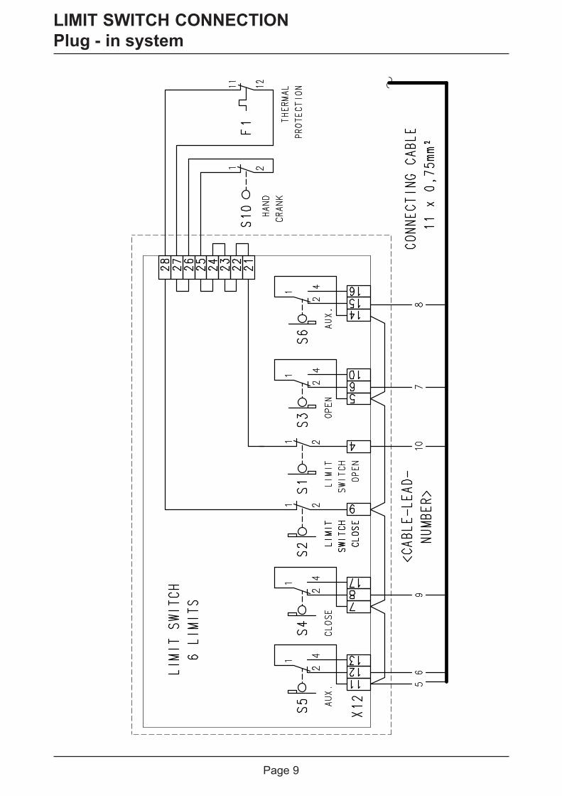
LIMIT SWITCH CONNECTION.....................................................................................9
Plug - in system ..........................................................................................................9
Terminal version (until year 1997) ..............................................................................10
MAINS SUPPLY ............................................................................................................11
MOTOR CONNECTION (internal wiring) ....................................................................12
PHASE ROTATION .......................................................................................................12
LIMIT SWITCH - ADJUSTMENT ..................................................................................13
HARDWARE OVERVIEW .............................................................................................14
WIRING DIAGRAM .......................................................................................................15
CONTROL PROGRAMMING........................................................................................16
Operating mode .........................................................................................................17
Functions ....................................................................................................................17
Maintenance cycle counter.........................................................................................17
MEMORY CHECK.........................................................................................................17
SAFETY DEVICES .......................................................................................................18
Mounting the spiral cable ..............................................................................................18
Emergency stop X3 ......................................................................................................18
Page

Page 3
FUNCTION DESCRIPTION ..........................................................................................18
Internal push button / Three push button / Key switch X5 .........................................18
Fully closed control .....................................................................................................18
Potential free changeover contact X9 .......................................................................19
Maintenance cycle counter.........................................................................................19
Short circuit / overload monitor ...................................................................................19
OPERATING STATUS DISPLAY ..................................................................................20
TECHNICAL DATA........................................................................................................21
LIFETIME / DOORCYKLES..........................................................................................22
DECLARATION OF INCORPORATION........................................................................23
FUNCTION OVERVIEW ...............................................................................................24
Page

Page 4
SAFETY DIRECTIONS
Safety Regulations
During the installation, initial operation, maintenance and testing of the ELEKTROMATEN®,it is necessary to observe the safety and accident-prevention regulations valid for the specificapplication.
In particular, you should observe the following regulations (this list is not exhaustive):European normativ- DIN EN 12453
Saftey in use of power operated doors - Requirements- DIN EN 12445
Saftey in use of power operated doors - Test methods
Please check normative´s bellow.VDE-regulations- DIN EN 418
Safety machineryEmergency stop equipment functional aspectsPrinciples for design
- DIN EN 60204-1 / VDE 0113-1Safety of machinery - Electrical equipment of machines - Part 1:General requirements
- DIN EN 60335-1 / VDE 0700-1Safety of household and similar electrical appliances - Part 1:General requirements
Basic DirectionsThis control has been built in accordance with DIN EN 12453 Industrial, commercial andgarage doors and gates - Safety in use of power operated doors - Requirements; and leftthe factory in perfect condition from the point of view of safety. To maintain this condition and toensure safe operation, the user must observe all the directions and warnings contained in theseoperating instructions.In principle, only trained electrical craftsmen should work on electrical equipment. They mustassess the work which has been assigned to them, identify potential danger sources and takesuitable safety precautions.Reconstruction of or changes to ELEKTROMATEN® are only permissible with the approval ofthe manufacturer. Original replacement parts and accessories authorised by the manufacturerguarantee safety. Liability ceases to apply if other parts are used.
The operational safety of an ELEKTROMATEN® is only guaranteed if it is used in accordancewith the regulations. The limiting values stated in the technical data should not be exceededunder any circumstances (see corresponding sections of the operating instructions).
Regulations- Please ensure that the local regulations relating to the Safety of Opera-
tions of Doors are followed

Page 5
SAFETY DIRECTIONS
Explanation of warnings
These operating instructions contain directions which are important for using the ELEKTRO-MATEN® appropriately and safely.
The individual directions have the following meaning:
DANGERThis indicates danger to the life and health of the user if the appropriateprecautions are not taken.
Please observe the safety and accident prevention regulations valid forthe specific application. The installation of the ELEKTROMATEN®, theopening of covers or lids and electrical connection must be carried outwhen the supply is switched off.
The ELEKTROMAT® must be installed with the authorised coverings andprotective devices. Care should be taken that any seals are fitted correctlyand screw couplings are tightened correctly.
In the case of ELEKTROMATEN® with a permanent mains connection, anall-pole main switch with appropriate back-up fuse must be provided.
Check live cables and conductors regularly for insulation faults orbreakages. When a fault is detected in the cabling, the defective cablingshould be replaced after immediately switching off the mains supply.
Before starting operation, check whether the permissible mains voltagerange of the devices corresponds to the local mains voltage.
With three – phase motor connection it must have right phase rotation
The following warnings are to be understood as a general guideline for working with theELEKTROMATEN® in conjunction with other devices. These directions must be observedstrictly during installation and operation.
General warnings and safety precautions
CAUTIONThis warns that the ELEKTROMATEN® or other materials may be damaged ifthe appropriate precautions are not taken.
Check that all screw connections are secure before operating the controland adjusting the limit switches.
Page 6
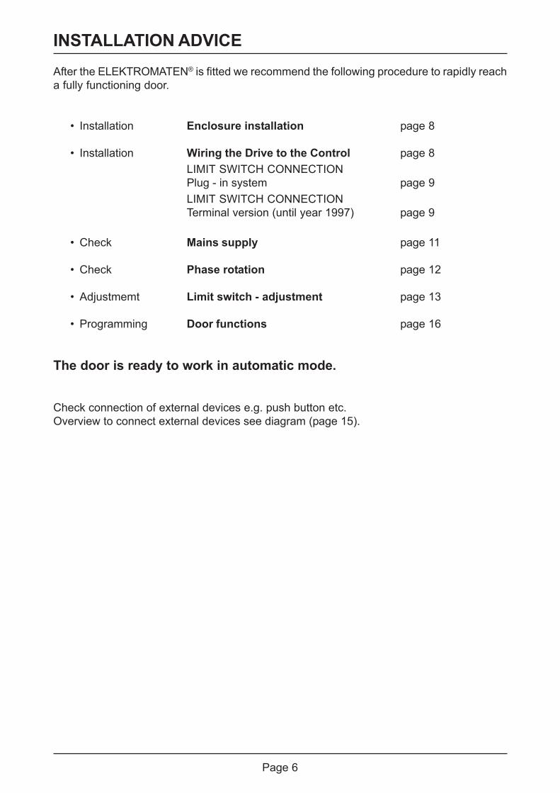
INSTALLATION ADVICEAfter the ELEKTROMATEN® is fitted we recommend the following procedure to rapidly reacha fully functioning door.
• Installation Enclosure installation page 8
• Installation Wiring the Drive to the Control page 8LIMIT SWITCH CONNECTIONPlug - in system page 9LIMIT SWITCH CONNECTIONTerminal version (until year 1997) page 9
• Check Mains supply page 11
• Check Phase rotation page 12
• Adjustmemt Limit switch - adjustment page 13
• Programming Door functions page 16
The door is ready to work in automatic mode.
Check connection of external devices e.g. push button etc.Overview to connect external devices see diagram (page 15).

Page 7
INSTALLATION OVERVIEW
Mains supply
Three push button
Emergency stop
Connection cable ELEKTROMAT® forMotor and mechanical limits NES 11
5
5
3
Spiral cable for pass-doorslack-wire switch
2
( ) Number of cores in the cable
Important!Using the connection cable out side the building is not permitted.

Page 8
ENCLOSURE INSTALLATION
Before mounting the enclosure, the surface has to be checked for flatness, slope and freedomfrom vibrations. Mounting must be vertical. It is important that the door can be clearly seenfrom the position of the control through-out its travel.
CONNECTING THE CONTROL AND THE ELEKTROMATEN®
After the drive and control are fitted they can be connected with a plug-in cable. The cablehas plugs on each end and for easy fitting. The plugs for motor and control panel are differentand cannot be interchanged.
Cable DescriptionMotor plug to control Panel
PIN - Wire-No.1 - 3 Phase W2 - 2 Phase V3 - 1 Phase U4 - 4 Neutral (N)5 - PE Earth
Limit switch plug to control panel
PIN - Wire-No.1 - 5 supply + 24V2 - 6 S 5 aux. limit for fully closed control only3 - 7 open - limit4 - 8 S 6 aux. limit potential-free relaiscontact5 - 9 close limit6 - 10 safety circuit common limit
Connection cable
Control panel TS 956 ELEKTROMAT®
1
2
PE
3
4
8
7
10
9
65
16151410
6549
1787
131211
3214
PE
- 1
- 2
- 3
- 4
- 5
PIN
- 14 -
5 -
6 -
- 2
- 3
PIN
Mot
or p
lug
Lim
it sw
itch
plug
Page 9
LIMIT SWITCH CONNECTIONPlug - in system

Page 10
LIMIT SWITCH CONNECTIONTerminal version (until year 1997)
M 3

Page 11
The CONTROL PANEL TS 956 has a universal electric supply and works with the followingsupplies. (See diagram Fig.1-5)
DANGER! To the life and health thru electric shock.Before mounting the mains supply must be switched OFF.
The supply disconnect device (Main switch or CEE plug) must be installed between 0,6mand 1,7m above floor level.
Mains supply terminal
Fig.: 1
Fig.: 2
Fig.: 3
Fig.: 5
Fig.: 4
asymmetric winding
symmetric winding
Important note!The bridge must be fitted into the right terminal otherwise the print could bedestroyed.
MAINS SUPPLY
External fuse!Control must be saved against short circuit and overload by an external fuse,max. 10A delayed, in the mains supply. An automatic cut off switch is required,regarding the supply for three-phase or single-phase.
When connecting control to mains supply a mains isolator switch or (16A CEE – plug) accordingEN 12453 is required.
400V – mains supply = 1.5 / 1.6230V – mains supply = 1.6 / 1.7

Page 12
Important Notice!After the Mains supply has been connected by inserting the CEE plug in theappropriate socket or turning on the main switch, confirm that the phase rotationis correct by checking that the door opens when the OPEN push button isoperated.If the door closes when operating the OPEN push button reverse two phasesat the terminal X1.
PHASE ROTATION
DANGER! To the life and health through electric shock.Before changing phase rotation the mains supply must be switched OFF.
Three-phase 3 x400 V AC, N, PEStar connection
Three-phase 3 x230 V AC, PEDelta connection
Single-phase 1x230 V AC, N, PEsymmetrical winding
Single-phase 1x230 V AC, N, PEasymmetrical winding
Important note!For 3x400V AC PE noneutral, the brakerectifier must beconnected betweenterminal V and star-point terminal.
brown
brown
supply forbrakerectifier
bluesupply forbrakerectifier
MOTOR CONNECTION (internal wiring)
blue
On several ELEKTROMATEN® the connection U1 und V1 on the motor-plug areinterchanged.

Page 13
LIMIT SWITCH - ADJUSTMENT
Working limit adjustment is completeThe door could be moved in DEADMAN mode UP/DOWNFurther adjustments see programming mode (Page 16)
1. Move the door to final open position
press button to reach upper limit
Door open
2. Adjustment final open limit
3. Move the door to final close position
press button to reach lower limit
Door close
4. Adjustment final close position
After checking the phase rotation, the limit switches must be adjusted in the following steps.When open and close position limits have been set the safety limits are automaticallypre-adjusted. Eventually fine adjustment could be required. Please see MechanicalOperating Instruction.
After reaching the final openposition the limit S3 must beswitched with green limit cam S3and panel display changes to„Door final open position“
After reaching the final closeposition the limit S4 must beswitched with green limit cam S4panel display changes to „Doorfinal close position“
Display shown-door open
Display shown-door closed
Display flashingduring the door
upwards movement
Displayshown - doorbetween finallimit positions
Display flashingduring doordownwardsmovement
Display shown-door between
final limitpositions

Page 14
HARDWARE OVERVIEW
Description Print:X1 Mains supply S1 Selector switch
external supply 230V V1 7-segment display1.9 = L1 fused with F1 = 1A MOT Motor connection1.8 = N NES Mechanical limit connection(only with 3 x 400V, N, PE und 1 x 230V, N, PE) Internal push button
X2 Pass-door plugX3 Emergency push buttonX5 Three push button / key switchX9 Potential free relay contact
X1
X9 X3
X2
X5
S1
V1

Page 15
WIRING DIAGRAM
Pag
e 18
- 1
9Three push button
stationKey switch with
stop button
Close
Stop
Open
Stop
Open /Close
Key switch intermediate stopAux. contact
Terminal box Bridge
passdoor / slack wireswitch contact
spiralcable
Open /Close
or
plug-inbridge
or
Emergencystop button
N L1L1 fused via
F1 = 1At

Page 16
CONTROL PROGRAMMING
5. Exit programming
Turn selector until display = 00 Press selector
and
1. Enter programming Mode
Press selector switch for 3 sec. until display = 00
2. Chose program and confirm
Turn selector press selector
3. Adjustment
Turn selector
4. Memorise
Press selector
and
Functionen
Functionen
further adjustments

Page 17
CONTROL PROGRAMMING
4. Memorise 3. Adjustment 2. Choose program and confirm
Pressselector
Dead man OPENDead man CLOSE
Door function
Self-hold OPENDead man CLOSE
fully closed control
MEMORY CHECK
Pressselector
Info Cycle counter7- digit
Program version will be displayed
Displayed
Info Program version
M HT ZT T H Z E
Pressselector
The cycles would be displayed as follow.M = 1.000.000 H = 100HT = 100.000 Z = 10ZT = 10.000 E = 1T = 1.000
2. Chose program and confirm
Pressselector
OFFRelay function
Switch contact impulse signal
Switch contact continuous
Operating mode
01-99 correspond from 1.000 up to99.000 Count down cycles
Counter adjustment
Display appears „CS“ and adjustednumber of cycles
Reaction whenreaching 0
Maintenance cycle counter
Pressselector
Pressselector
Functions
Changing to Hold-to-run mode in upwardsdirection, if adjusted Menu 0.1 doorfunction

Page 18
Internal push button / Three push button / Key switch X5Internal and external push buttonInternal and external push button working seperately from each other. Pushing at the sametime, the internal push button has priority.
Important note!In Dead man mode the user shall be in full view of the door throughout itstravel.
FUNCTION DESCRIPTION
Emergency stop X3These terminals are to connect an emergency stop button according to DIN EN 418.Alternatively the terminals can be used to connect a safety device against entrapment (e.g.self-testing light barrier).
SAFETY DEVICES
Mounting the spiral cableA bush is provided on both sides of the control box for mounting the spiral cable.Push the plugs through, into the enclosure until there is sufficient cable to allow the plug tobe connected to the board.If passdoor / slack wire switch contact exists, remove bridge at terminal ST and ST+ inthe terminal box. The plug at terminal X2 must be removed.
Fully closed controlAt this function the self-hold should be activate. The pushbutton must be pressed until theshutter reaches the final limit. Otherwise the door opens in self-hold automatically.To activate this function, set Menu 0.1 Adjustment 0.5 - and set pre limit S5 before the finallimit close.
Important note!If pre limit S5 is not adjusted, shutter closing is not possible.

Page 19
For functioning as a switching contact, impulse or continuous, the switching position must beadjusted by limit switch S6.
Impulse signal On reaching the limit switch the relay contact is made for 1 second.
Continuous signal Relay contact is activated as long the limit switch is made.
Potential free changeover contact X9In menu 2.5 this contact is able to work for several functions.
Important note!It is only possible to work with one adjusted function.
Short circuit / overload monitorThe control TS 956 provides 230V AC for external devices.
230V AC; max. 1A
In case of short-cut or an overload, the red spot in the display, disappears.Check F1 if the Display is dark.
Maintenance cycle counterFree adjustable maintenance cycle counter Menu 8.5 makes it possible to pre-adjust a max.No of cycles until a maintenance is agreed.
The no of cycles can be adjusted from 1.000 up to 99.000; the adjustment is possible insteps of 1.000 cycles.
Different reactions can be chosen if the point of pre- adjusted maintenance cycles has beenreached, see Menu 8.6Whenever the final open limit has been contacted the pre-adjusted number will be reducedwith 1 until 0 is reached.
When maintenance was done the cycle counter could be re-adjusted to a new maintenanceperiod and count down starts again.
FUNCTION DESCRIPTION

Page 20
open command being given
stop command being given
close command being given
Report Command description
If the normally displayed red spot is out = Short circuit or overload on the supply→→→→→
OPERATING STATUS DISPLAY
The control TS956 can display up to threedifferent status conditions one after another. Eachstatus is displayed with a letter and a number. The letter and the number are flashing alternately,thereby the control differentiates between a FAULT = F and a command = E.
Report Description Measure to solve the problem
Pass door contact open Check the proper operation of pass door contact, orwhether the supply cable is broken
Emergency stop activated Check the emergency stop is activated, or whether thesupply cable is broken
Safety open or close limitoperated
Turn mains supply OFF and move the shutter downwards- with the manual operator- until the safety limit is freeor the open limit should be re-adjusted.
Emergency operator ormotor-winding thermal pro-tection operated
Check emergency operator or whether the drive unit isoverloaded.
Phase rotation failure Check main supply phase rotation turns right
Failure pass door contactX 2.1- X 2.2
Check pass door circuit’s transition resistance andweather pass door switch works
Failure input pass doorX 2.1- X 2.2
For reset switch control panel OFF-ON
Page 21
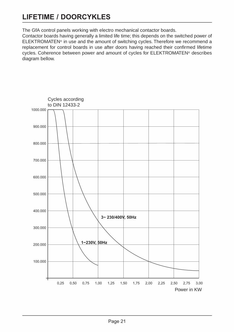
LIFETIME / DOORCYKLES
The GfA control panels working with electro mechanical contactor boards.Contactor boards having generally a limited life time; this depends on the switched power ofELEKTROMATEN® in use and the amount of switching cycles. Therefore we recommend areplacement for control boards in use after doors having reached their confirmed lifetimecycles. Coherence between power and amount of cycles for ELEKTROMATEN® describesdiagram bellow.
100.000
0,25 0,50 0,75 1,00 1,25 1,50 1,75 2,00 2,25
3~ 230/400V, 50Hz
1~230V, 50Hz
2,50 2,75 3,00
200.000
300.000
400.000
500.000
600.000
700.000
800.000
900.000
Leistung in kW
Torzyklennach DIN EN 12433-2
1000.000
Cycles accordingto DIN 12433-2
Power in KW

Page 22
TECHNICAL DATA
Housing Dimensions 190mm x 300mm x 115mm (B x H x T)Mounting verticalELEKTROMATEN® Supply Three-phase 3 x 230 / 400V AC ± 5%, 50...60Hz
Single-phase 1 x 230V ± 5%, 50...60HzPower max. at 3 x 400V AC, max. 3kW
Control supply via L1,L2 400V AC or 230V AC + - 10%, 50-...60Hz,voltage changing with bridge to 3- pol terminal,safety fuse F1 (1A t)
External supply fuse 10A delayedPermitted Load ca. 15 VA (without motor and ext. 230V)External supply 1 230V via L1 and N, safety fuse F1 (1A t)Inputs 24V DC / typ. 10mA
signal length must be more than 100msRelay output If inductive loads are to be switched (e.g. other relays)
those have to be protected with free-wheeling Diodescontact load at 230V max. 1A
Temperature Working: -5.... +40°CStorage: +0....+50°C
Humidity: To 93% not condensingVibration: Vibration free mounting, e.g. on flat built wallProtection class CEE Plug IP54, IP65 deliverable
Page 23
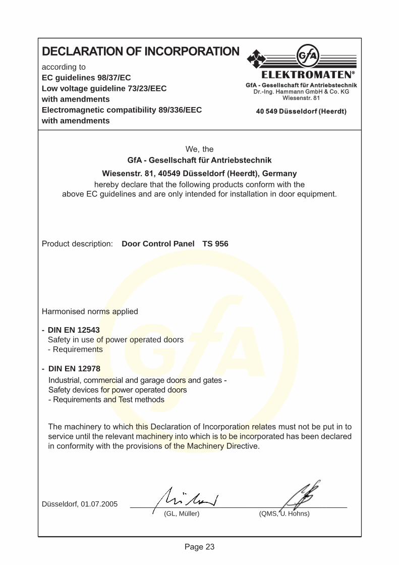
Harmonised norms applied
- DIN EN 12543Safety in use of power operated doors- Requirements
- DIN EN 12978Industrial, commercial and garage doors and gates -Safety devices for power operated doors- Requirements and Test methods
We, theGfA - Gesellschaft für Antriebstechnik
Wiesenstr. 81, 40549 Düsseldorf (Heerdt), Germanyhereby declare that the following products conform with the
above EC guidelines and are only intended for installation in door equipment.
according toEC guidelines 98/37/ECLow voltage guideline 73/23/EECwith amendmentsElectromagnetic compatibility 89/336/EECwith amendments
DECLARATION OF INCORPORATION
The machinery to which this Declaration of Incorporation relates must not be put in toservice until the relevant machinery into which is to be incorporated has been declaredin conformity with the provisions of the Machinery Directive.
Düsseldorf, 01.07.2005 _____________________________________________________ (GL, Müller) (QMS, U. Hohns)
Product description: Door Control Panel TS 956

Page 24
FUNCTION OVERVIEW
• Conrol panel for ELEKTROMATEN® up to. 3 kW at 400V / 3~ phase with mechanicallimits
• 7- Segment led display showing- Programming the control panel- Displays Command - / Info- / Fault
• Mains supply- 400V / 3~ with and without Neutral- 230V / 3~- 230V / 1~ (for single-phase motors)
• Door operating modes- Dead-man open- and close- Self-hold open- and dead-man mode close- fully closed control
• supply for external devices- 230V (at 400V / 3~ with N), up to 1A load
• Plug connection for the motor (5 - pole) and limit switches (6- pole)
• Plug for spiral cable (safety edge and pass-door contact)
• Internal pushbutton OPEN / STOP / CLOSE
• Additional terminals for different control equipment- Emergency stop (LATCHING)- additional safety stops- external three push button OPEN / STOP / CLOSE- 1x potential free relay output (NC / NO), output signal from aux. limit