Embed Size (px)
Citation preview
GCPS 2019
__________________________________________________________________________
Don't Let Your Safe Operating Limits Leave You S-O-L
(Out of Luck)
Todd Stauffer
Exida Consulting, LLC
Sellersville, PA
Denise Chastain-Knight
Exida Consulting, LLC
Sellersville, PA
Copyright exida, 2019, all rights reserved.
Prepared for Presentation at
American Institute of Chemical Engineers
2019 Spring Meeting and 15th Global Congress on Process Safety
New Orleans, LA
March 31 – April 3, 2019
AIChE shall not be responsible for statements or opinions contained
in papers or printed in its publications
GCPS 2019
__________________________________________________________________________
Don't Let Your Safe Operating Limits Leave You S-O-L
(Out of Luck)
Todd Stauffer
Exida Consulting, LLC
Sellersville, PA
Denise Chastain-Knight
Keywords: Safe Operating Limits, Design Limits, Never Exceed Limits, SOL Exceedances, Tier
3 Leading Indicators, Process Safety Information,
Abstract
Collection and Utilization of process safety metrics is an important tool for driving improved
safety. Tier 3 leading indicators (challenges to safety system) indicate failures of process safety
management systems and highlight areas that should be improved to prevent a more serious
event. Safe Operating Limit (SOL) exceedances are a commonly used Tier 3 leading indicator.
Surprisingly, there are many different approaches used in industry to calculate safe operating
limits and to apply them. This inconsistency potentially diminishes the usefulness of SOL
exceedances as an effective indicator.
This paper discusses current industry practices around the determination and application of safe
operating limits as established by a recent benchmark survey of over 150 safety practitioners
from around the world. Areas explored in the survey of SOLs include; methodology for
calculating, how / where information is stored, how / when established values are reviewed and
audited, usage as a Process Safety Management Leading indicator, integration with operations
(training, documentation), identification and tracking of when exceedances have occurred, and
actions taken on exceedance. Key results and conclusions will be presented as well as
recommendations on where industry should focus on improvement.
1 Introduction
Determination and documentation of Safe Operating Limits (SOLs), the limits beyond which
would be considered upset conditions, is required per the OSHA Process Safety Management
(PSM) Regulation 1910.119. SOLs and associated consequences of deviation that could occur if
these limits were violated are considered part of the Process Safety Information (PSI) [1].
Exceeding Safe Operating Limits are considered a Tier 3 Process Safety Management Leading
Indicator per API RP-754 [2]. SOLs are typically documented in operating procedures and
should be well known and understood by the operations team, including how to respond to
GCPS 2019
__________________________________________________________________________
prevent the potential consequence (the consequence of deviation). SOL values should be firmly
established to support HAZOP analysis and evaluation of process changes as part of
management of change (MOC).
Despite the broad applicability across industry, the determination and application of SOLs often
varies from company to company. An industry benchmark study was conducted amongst 152
functional safety practitioners from around the world. The survey respondents were asked both
multiple choice and short answer questions.
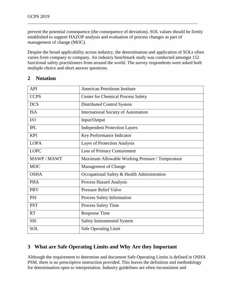
2 Notation
API American Petroleum Institute
CCPS Center for Chemical Process Safety
DCS Distributed Control System
ISA International Society of Automation
I/O Input/Output
IPL Independent Protection Layers
KPI Key Performance Indicator
LOPA Layer of Protection Analysis
LOPC Loss of Primary Containment
MAWP / MAWT Maximum Allowable Working Pressure / Temperature
MOC Management of Change
OSHA Occupational Safety & Health Administration
PHA Process Hazard Analysis
PRV Pressure Relief Valve
PSI Process Safety Information
PST Process Safety Time
RT Response Time
SIS Safety Instrumented System
SOL Safe Operating Limit
3 What are Safe Operating Limits and Why Are they Important
Although the requirement to determine and document Safe Operating Limits is defined in OSHA
PSM, there is no prescriptive instruction provided. This leaves the definition and methodology
for determination open to interpretation. Industry guidelines are often inconsistent and

GCPS 2019
__________________________________________________________________________
contradictory in methodology and terminology. Following are the definitions for SOL from
CCPS, ISA, and API industry guidelines.
Safe Operating Limit (SOL) - Limits established for critical process parameters, such as
temperature, pressure, level, flow, or concentration, based on a combination of equipment design
limits and the dynamics of the process [3,4].
Safe Operating Limit (SOL) – A value for a critical operating parameter (e.g., low/high pressure,
level, temperature, pH, composition, and flow) that defines the equipment or process unit safe
operating envelope beyond which a process will not intentionally be operated due to the risk of
imminent catastrophic equipment failure or loss of containment. Operational or mechanical
corrective action ceases and immediate predetermined actions are taken at these critical operating
parameter values in order to bring equipment and process units to a safe state [5].
Safe Operating Limit (SOL) – value for a critical operating parameter outside of the normal
operating limits defining a threshold of abnormal process condition beyond which predetermined
actions are taken in order to avoid a hazardous event and return the process to a safe state.
NOTE 1: The definition of "safe state" can be different for different protection layers, such as
returning the process to the normal operating limits or safely shutting down the equipment.
NOTE 2: Exceeding a safe operating limit is indicative of an abnormal operating condition.
NOTE 3: The IPL setpoint can coincide with a SOL in some cases [6].
Figure 1 below provides a means to visualize Safe Operating Limits as applied to API-RP 754,
where SOL exceedances are defined as a Tier 3 Process Safety Performance leading indicator.
Figure 1. Safe Operating Limits [7]
GCPS 2019
__________________________________________________________________________
Safe Operating Limits represent the point beyond which troubleshooting ends and pre-
determined action occurs to return the process to a known safe state. Pre-determined actions may
range from manually executed operating procedures to a fully automated safety instrumented
system [8]. Operating outside the Safe Operating Limits results in a higher probability of Loss of
Primary Containment [7].
Consolidating key aspects of the definitions above yields the following elements for discussion
of safe operating limits. Safe operating limits:
• Are values of critical operating parameters (e.g., low/high pressure, level, temperature,
pH, composition, and flow) outside of the normal operating limits.
• Are established based on a combination of equipment design limits and the dynamics of
the process.
• Define the equipment or process unit safe operating envelope beyond which a process
will not intentionally be operated due to the risk of imminent catastrophic equipment
failure or loss of containment.
• Represent the point at which troubleshooting ceases and immediate predetermined
actions are taken in order to bring equipment and process units to a safe state. Pre-
determined actions may range from manually executed operating procedures to a fully
automated safety instrumented system.
4 Survey Demographics
Over 150 functional safety practitioners from around the world participated in the survey. The
table below shows the major countries that were represented.
Table 1. Top Respondents by Country
# Country % of Respondents
1 United States 30.9%
2 Canada 6.6%
2 India 6.6%
2 United Kingdom 6.6%
5 Australia 4.6%
6 Netherlands 4.0%
7 Brazil 2.6%
7 Germany 2.6%
Other 25.3%
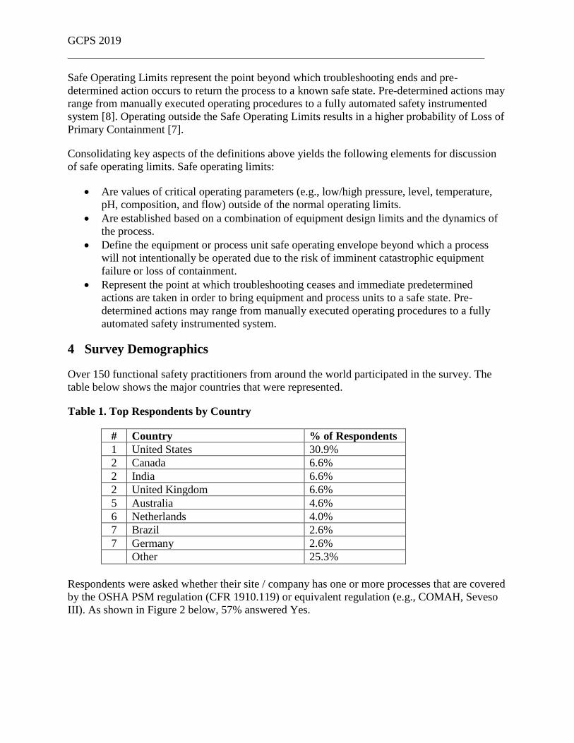
Respondents were asked whether their site / company has one or more processes that are covered
by the OSHA PSM regulation (CFR 1910.119) or equivalent regulation (e.g., COMAH, Seveso
III). As shown in Figure 2 below, 57% answered Yes.
GCPS 2019
__________________________________________________________________________
Figure 2. Respondents having processes covered by a Process Safety Regulation
5 Survey Results
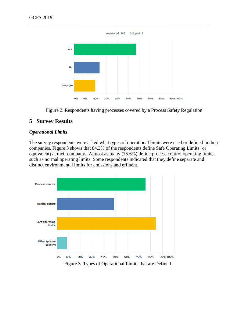
Operational Limits
The survey respondents were asked what types of operational limits were used or defined in their
companies. Figure 3 shows that 84.3% of the respondents define Safe Operating Limits (or
equivalent) at their company. Almost as many (75.6%) define process control operating limits,
such as normal operating limits. Some respondents indicated that they define separate and
distinct environmental limits for emissions and effluent.
Figure 3. Types of Operational Limits that are Defined
GCPS 2019
__________________________________________________________________________
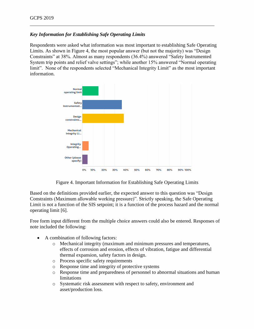
Key Information for Establishing Safe Operating Limits
Respondents were asked what information was most important to establishing Safe Operating
Limits. As shown in Figure 4, the most popular answer (but not the majority) was “Design
Constraints” at 38%. Almost as many respondents (36.4%) answered “Safety Instrumented
System trip points and relief valve settings”; while another 15% answered “Normal operating
limit”. None of the respondents selected “Mechanical Integrity Limit” as the most important
information.
Figure 4. Important Information for Establishing Safe Operating Limits
Based on the definitions provided earlier, the expected answer to this question was “Design
Constraints (Maximum allowable working pressure)”. Strictly speaking, the Safe Operating
Limit is not a function of the SIS setpoint; it is a function of the process hazard and the normal
operating limit [6].
Free form input different from the multiple choice answers could also be entered. Responses of
note included the following:
• A combination of following factors:
o Mechanical integrity (maximum and minimum pressures and temperatures,
effects of corrosion and erosion, effects of vibration, fatigue and differential
thermal expansion, safety factors in design.
o Process specific safety requirements
o Response time and integrity of protective systems
o Response time and preparedness of personnel to abnormal situations and human
limitations
o Systematic risk assessment with respect to safety, environment and
asset/production loss.
GCPS 2019
__________________________________________________________________________
• Process safety time - which depends on the relevant design constraints (not just pressure)
and on the dynamic behavior of the process.
• In our systems, the process media for a specific parameter e.g. pressure, or temp. has
different layers as below:
o Never Exceed (Low/ High)
o Safe Operating Limit (Low/ High)
o Interlock Levels (Low/ High)
o Alarm Levels (Low/ High)
o Operating Range (Low/ High)
The Process for Establishing Safe Operating Limits
As a follow up to the previous question, respondents were asked to describe, at a high level, the
process for defining SOLs. Responses of note included the following:
• Mechanical design
o Maximum Allowable Over Pressure is the determination for most safe operating
limits in the facility
o Safe Operating Limit are defined by taking into consideration the design
constraints (design values) of the operating equipment. Based on the metallurgy
and other factors the mechanical integrity values are determined. The safe
operating limits are then defined at these mechanical integrity values
o Based on mechanical design limits, process design limits for safe operation,
response time and reliability limitations of protective systems/measures and
systematic risk assessment.
o Limit is set at 90% of equipment's MAWP and/or Temperature.
o The safe operating limits are usually below the maximum allowable working
limits.
• Process consideration
o Safe Operating Limits are governed by the process design requirements. As per
the intended process, Safe operating limits are defined and then mechanical
design limits are identified.
o process flow in & out from the equipment in question and the time required to get
to high level (alert level), generally it is 5-10%of the higher limit
o as per the normal operating values of the process flow diagrams and material and
heat balances
o The process dynamic analysis is used to set limits based on inventories, flowrates,
pressures, temperatures, flow or pressure relief capacity, design safety margin,
etc.
o For high level, threshhold value is the level at which entrainement can take place
is given by the Process engineer which is configured as SIS set point. Safe
operating limit : Depending on the volume and time taken to reach the SIS level
from a high level alarm is generated Example : 40-55% safe operating level and
75% is SIS set level. margin of 20% approximately has process safety time of 30
minutes
• Process and mechanical consideration

GCPS 2019
__________________________________________________________________________
o It's a combination of equipment design constraints and process technology
information; the more restrictive of the two becomes the SOL
o Inferred from equipment design limits or process simulation and defined such that
safety systems can respond fast enough if the process exceeds the SOL .
o Safe operating limits are defined based on RBI (Risk based inspection), design
and operational constraints.
o During the plant design (plant subject of a project) Safe Operating Limits are
established to avoid: damages to equipment with consequence of injuries, loss of
containment and loss of production mainly
o Safety margin applied to materials and process values
o We apply a safety factor on Design limits. This factor is based on mechanical
integrity and operational constraints
o Process engineering defines safe operating limits based upon equipment design,
system capacity, static/dynamic operating conditions.
o A range outside of the normal operating limits beyond which LOPC or other
serious process safety events can occur (runaway reactions, etc.). SOLs still
provide a buffer between the boundary of the SOLs and the equipment limits
(MAWP, etc.) to provide response time in the process shutdown before a
catastrophic loss of containment should occur.
o Safe operating limits is defined as limits based on flow, temperature, pressure,
and levels in accordance with the mechanical equipment and process conditions.
• Set to match (e.g. interlock trip, relief set point)
o In many cases, it is not available or assumed to be equal to the interlock / relief
valve settings.
o Currently SOLs are the design constraints or process safety time.
Storing Official Record of Safe Operating Limits
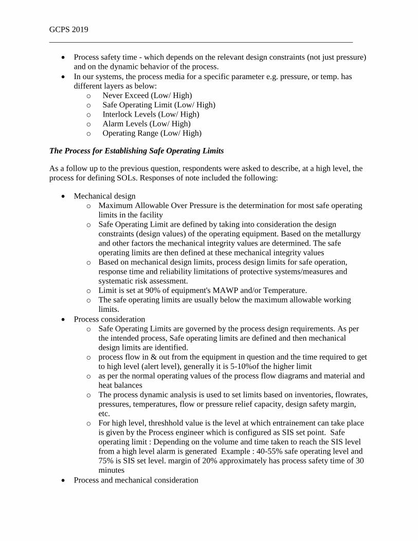
Respondents were asked about the location for the official repository of SOL information. Figure
5 shows that the results ranged from 32% for a “Documentation System”, to 30% for the “Unit
Operating Procedure” to 18% for a “Spreadsheet”. The main documentation systems mentioned
included Documentum, SAP, Dymenzions, and MS Sharepoint. Other responses included
P&IDs, Equipment & Piping data sheets, SRS, and SIF datasheets.
GCPS 2019
__________________________________________________________________________
Figure 5 – Storage Location for Safe Operating Limits
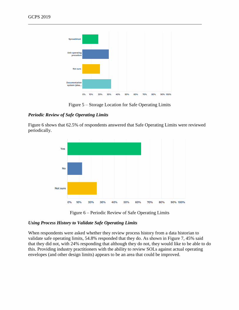
Periodic Review of Safe Operating Limits
Figure 6 shows that 62.5% of respondents answered that Safe Operating Limits were reviewed
periodically.
Figure 6 – Periodic Review of Safe Operating Limits
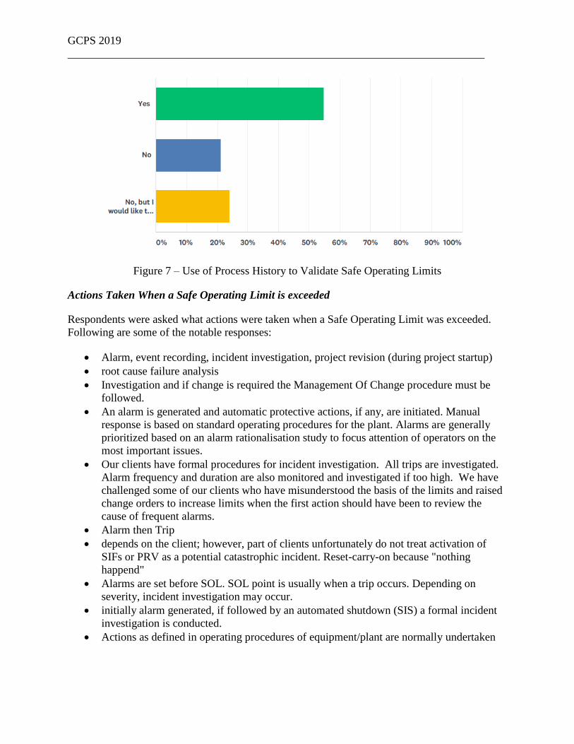
Using Process History to Validate Safe Operating Limits
When respondents were asked whether they review process history from a data historian to
validate safe operating limits, 54.8% responded that they do. As shown in Figure 7, 45% said
that they did not, with 24% responding that although they do not, they would like to be able to do
this. Providing industry practitioners with the ability to review SOLs against actual operating
envelopes (and other design limits) appears to be an area that could be improved.
GCPS 2019
__________________________________________________________________________
Figure 7 – Use of Process History to Validate Safe Operating Limits
Actions Taken When a Safe Operating Limit is exceeded
Respondents were asked what actions were taken when a Safe Operating Limit was exceeded.
Following are some of the notable responses:
• Alarm, event recording, incident investigation, project revision (during project startup)
• root cause failure analysis
• Investigation and if change is required the Management Of Change procedure must be
followed.
• An alarm is generated and automatic protective actions, if any, are initiated. Manual
response is based on standard operating procedures for the plant. Alarms are generally
prioritized based on an alarm rationalisation study to focus attention of operators on the
most important issues.
• Our clients have formal procedures for incident investigation. All trips are investigated.
Alarm frequency and duration are also monitored and investigated if too high. We have
challenged some of our clients who have misunderstood the basis of the limits and raised
change orders to increase limits when the first action should have been to review the
cause of frequent alarms.
• Alarm then Trip
• depends on the client; however, part of clients unfortunately do not treat activation of
SIFs or PRV as a potential catastrophic incident. Reset-carry-on because "nothing
happend"
• Alarms are set before SOL. SOL point is usually when a trip occurs. Depending on
severity, incident investigation may occur.
• initially alarm generated, if followed by an automated shutdown (SIS) a formal incident
investigation is conducted.
• Actions as defined in operating procedures of equipment/plant are normally undertaken
GCPS 2019
__________________________________________________________________________
• An investigation is done why it has occurred and depending on the outcome e.g.
instrument failure, real process failure, decisions is made how to prevent that in the
future.
• Alarm generated when a safe operating limit is exceeded. KPI system to capture the
number of critical alarms generated are recorded as Lagging indicators in Process Safety
KPI
• Process review will be carried out and alarm setting reviewed and process incident will
also be reviewed. Result of the review will be analysed and measures put in place to
forestall reoccurrence. This will be documented and cascaded to relevant persons
• "Near miss" event recorded and possibly investigated.
85% of respondents also reported that Safe Operating Limit exceedances needed to be reported
to management.
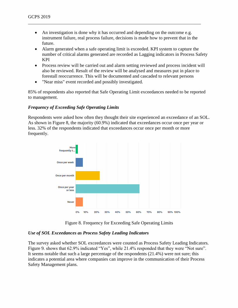
Frequency of Exceeding Safe Operating Limits
Respondents were asked how often they thought their site experienced an exceedance of an SOL.
As shown in Figure 8, the majority (60.9%) indicated that exceedances occur once per year or
less. 32% of the respondents indicated that exceedances occur once per month or more
frequently.
Figure 8. Frequency for Exceeding Safe Operating Limits
Use of SOL Exceedances as Process Safety Leading Indicators
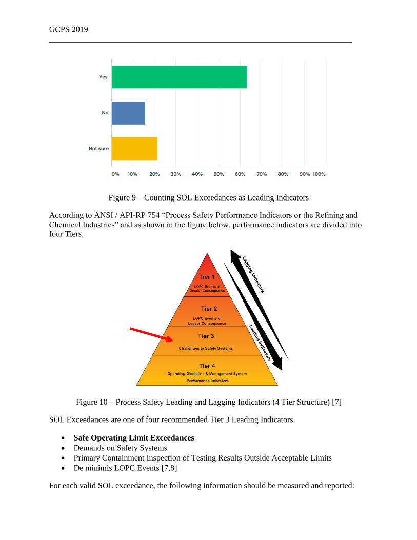
The survey asked whether SOL exceedances were counted as Process Safety Leading Indicators.
Figure 9. shows that 62.9% indicated “Yes”, while 21.4% responded that they were “Not sure”.
It seems notable that such a large percentage of the respondents (21.4%) were not sure; this
indicates a potential area where companies can improve in the communication of their Process
Safety Management plans.
GCPS 2019
__________________________________________________________________________
Figure 9 – Counting SOL Exceedances as Leading Indicators
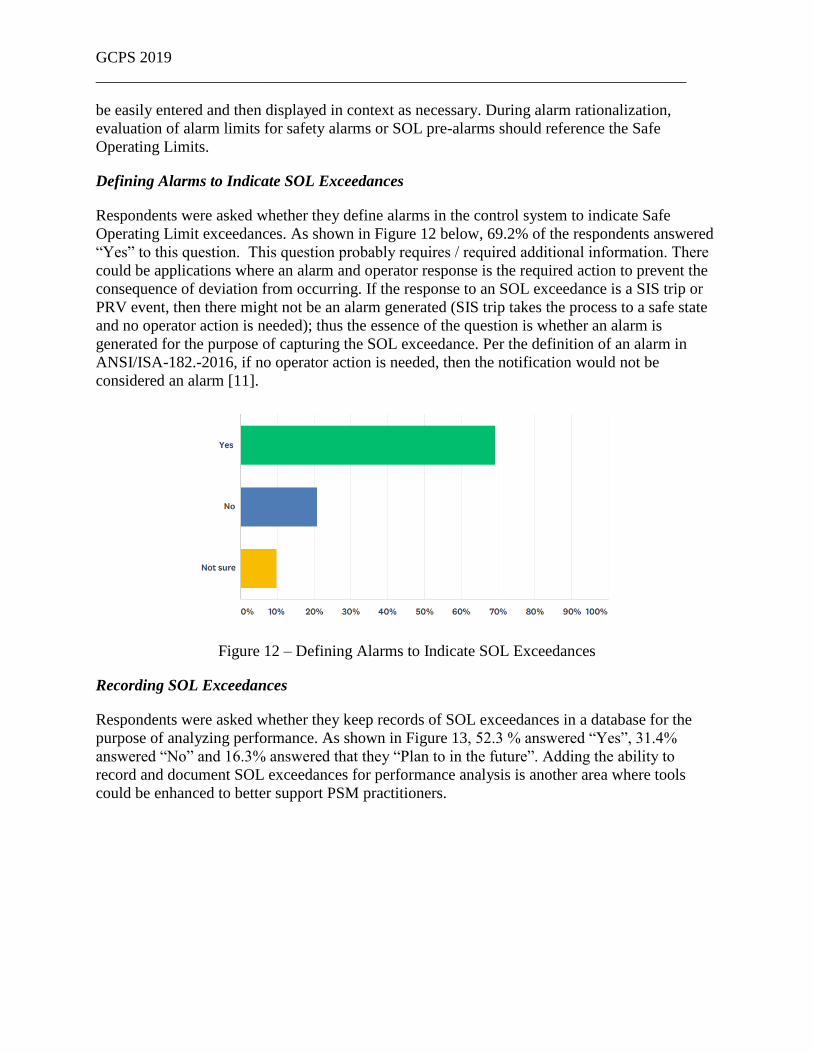
According to ANSI / API-RP 754 “Process Safety Performance Indicators or the Refining and
Chemical Industries” and as shown in the figure below, performance indicators are divided into
four Tiers.
Figure 10 – Process Safety Leading and Lagging Indicators (4 Tier Structure) [7]
SOL Exceedances are one of four recommended Tier 3 Leading Indicators.
• Safe Operating Limit Exceedances
• Demands on Safety Systems
• Primary Containment Inspection of Testing Results Outside Acceptable Limits
• De minimis LOPC Events [7,8]
For each valid SOL exceedance, the following information should be measured and reported:

GCPS 2019
__________________________________________________________________________
• peak value,
• duration of exceedance, and
• description of the initiating cause.
Frequent and/or prolonged SOL exceedances should be investigated to determine the initiating
cause and the barrier failure [7].
Operator Training and Awareness of Safe Operating Limits
Respondents were asked whether their operators are trained and made aware of the Safe
Operating Limits for the process units they monitor and control. The majority of respondents
(82.6%) answered “Yes”, while 3.3% answered “No” and 14.1% were “Not Sure”.
Figure 11 – Operator Training / Awareness of Safe Operating Limits
Per the OSHA PSM regulation, operating procedures are required to document (safe) operating
limits, consequences of deviation, and the steps required to correct or avoid deviation; therefore,
it should be expected that 100% of operators are trained and aware of relevant safe operating
limits. SOL-related alarms will likely be some of the highest priority alarms in the system;
operators should be trained to understand their importance [3]. This might be a relevant learning
that industry can get better at ensuring operators are trained on the Safe Operating Limits for
their areas of responsibility. Additional recommendations on how to optimize operator response
to SOL-related alarms can be found in previous works [9,10].
Making Safe Operating Limit Information Available during PHA, LOPA, and Alarm
Rationalization
Respondents were asked whether it would be beneficial to have Safe Operating Limit
information available during a PHA / LOPA and during alarm rationalization. Approximately
95% of the respondents answered “Yes” to both of these questions.
This result also introduces an area that could be improved. PHA / LOPA and alarm
rationalization tools could potentially be improved to allow Safe Operating Limit information to
GCPS 2019
__________________________________________________________________________
be easily entered and then displayed in context as necessary. During alarm rationalization,
evaluation of alarm limits for safety alarms or SOL pre-alarms should reference the Safe
Operating Limits.
Defining Alarms to Indicate SOL Exceedances
Respondents were asked whether they define alarms in the control system to indicate Safe
Operating Limit exceedances. As shown in Figure 12 below, 69.2% of the respondents answered
“Yes” to this question. This question probably requires / required additional information. There
could be applications where an alarm and operator response is the required action to prevent the
consequence of deviation from occurring. If the response to an SOL exceedance is a SIS trip or
PRV event, then there might not be an alarm generated (SIS trip takes the process to a safe state
and no operator action is needed); thus the essence of the question is whether an alarm is
generated for the purpose of capturing the SOL exceedance. Per the definition of an alarm in
ANSI/ISA-182.-2016, if no operator action is needed, then the notification would not be
considered an alarm [11].
Figure 12 – Defining Alarms to Indicate SOL Exceedances
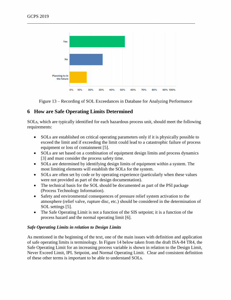
Recording SOL Exceedances
Respondents were asked whether they keep records of SOL exceedances in a database for the
purpose of analyzing performance. As shown in Figure 13, 52.3 % answered “Yes”, 31.4%
answered “No” and 16.3% answered that they “Plan to in the future”. Adding the ability to
record and document SOL exceedances for performance analysis is another area where tools
could be enhanced to better support PSM practitioners.
GCPS 2019
__________________________________________________________________________
Figure 13 – Recording of SOL Exceedances in Database for Analyzing Performance
6 How are Safe Operating Limits Determined
SOLs, which are typically identified for each hazardous process unit, should meet the following
requirements:
• SOLs are established on critical operating parameters only if it is physically possible to
exceed the limit and if exceeding the limit could lead to a catastrophic failure of process
equipment or loss of containment [5].
• SOLs are set based on a combination of equipment design limits and process dynamics
[3] and must consider the process safety time.
• SOLs are determined by identifying design limits of equipment within a system. The
most limiting elements will establish the SOLs for the system.
• SOLs are often set by code or by operating experience (particularly when these values
were not provided as part of the design documentation).
• The technical basis for the SOL should be documented as part of the PSI package
(Process Technology Information).
• Safety and environmental consequences of pressure relief system activation to the
atmosphere (relief valve, rupture disc, etc.) should be considered in the determination of
SOL settings [5].
• The Safe Operating Limit is not a function of the SIS setpoint; it is a function of the
process hazard and the normal operating limit [6].
Safe Operating Limits in relation to Design Limits
As mentioned in the beginning of the text, one of the main issues with definition and application
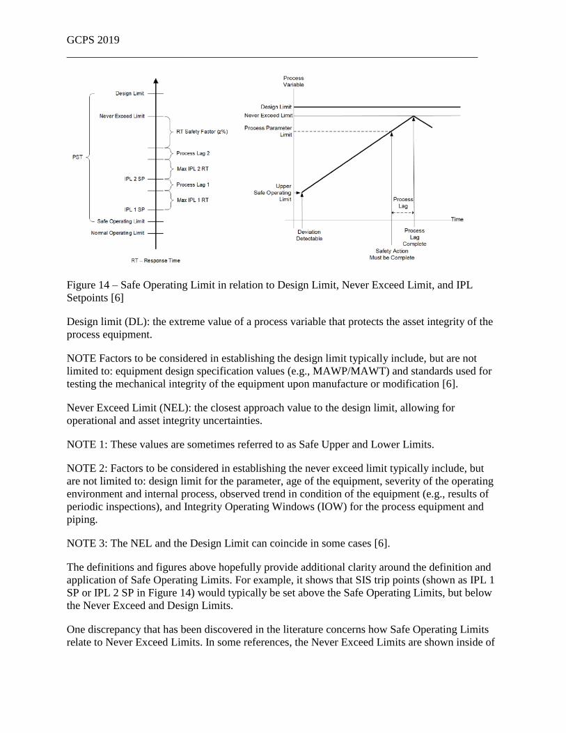
of safe operating limits is terminology. In Figure 14 below taken from the draft ISA-84 TR4, the
Safe Operating Limit for an increasing process variable is shown in relation to the Design Limit,
Never Exceed Limit, IPL Setpoint, and Normal Operating Limit. Clear and consistent definition
of these other terms is important to be able to understand SOLs.
GCPS 2019
__________________________________________________________________________
Figure 14 – Safe Operating Limit in relation to Design Limit, Never Exceed Limit, and IPL
Setpoints [6]
Design limit (DL): the extreme value of a process variable that protects the asset integrity of the
process equipment.
NOTE Factors to be considered in establishing the design limit typically include, but are not
limited to: equipment design specification values (e.g., MAWP/MAWT) and standards used for
testing the mechanical integrity of the equipment upon manufacture or modification [6].
Never Exceed Limit (NEL): the closest approach value to the design limit, allowing for
operational and asset integrity uncertainties.
NOTE 1: These values are sometimes referred to as Safe Upper and Lower Limits.
NOTE 2: Factors to be considered in establishing the never exceed limit typically include, but
are not limited to: design limit for the parameter, age of the equipment, severity of the operating
environment and internal process, observed trend in condition of the equipment (e.g., results of
periodic inspections), and Integrity Operating Windows (IOW) for the process equipment and
piping.
NOTE 3: The NEL and the Design Limit can coincide in some cases [6].
The definitions and figures above hopefully provide additional clarity around the definition and
application of Safe Operating Limits. For example, it shows that SIS trip points (shown as IPL 1
SP or IPL 2 SP in Figure 14) would typically be set above the Safe Operating Limits, but below
the Never Exceed and Design Limits.
One discrepancy that has been discovered in the literature concerns how Safe Operating Limits
relate to Never Exceed Limits. In some references, the Never Exceed Limits are shown inside of

GCPS 2019
__________________________________________________________________________
the Safe Operating Limits [5]. This disagrees with the portrayal of Never Exceed Limits being
outside of the SOLs as shown above in Figure 14 above.
7 Conclusion
Consistent definition and application of Safe Operating Limits is important to maintaining the
process safety of hazardous plants and is integral to the following:
• Unit Operating Procedures and Emergency Shutdown Procedures
• Calculation of Tier 3 Process Safety Events (Leading Indicators)
• Management of Change - Evaluation of whether a proposed change takes the process
conditions outside of its safe operating limits [12]
As shown in this paper, the definition (calculation) of Safe Operating Limits has significant
variability. Some of the key takeaways regarding definition of SOLs include:
• When evaluating Design Limits it is important to include the effects of Mechanical
Integrity and Integrity Operating Windows in addition to design constraints such as
MAWP or MAWT.
• Many practitioners set SOLs based on Design Limits such as MAWP. Some set SOL
values equal to MAWP, others include a Safety Factor (e.g., SOL = 0.9 MAWP).
• The rate at which a scenario develops should be considered when setting SOL to assure
there is sufficient time to take corrective action and return the process to a safe state.
• Industry would benefit by having more published examples of SOL calculations, such as
those shown by Sutton [13].
• Inconsistent terminology makes it difficult to apply SOLs; for example, some references
show SOLs falling outside of Never Exceed Limits.
Some of the key takeaways regarding application of SOLs include:
• Industry can improve operator training and visibility to the SOLs in their area of
responsibility.
• Significant variability exists in where the official record of SOLs are stored, from unit
operating procedure to Excel spreadsheet to Documentation system under access control.
• Industry can improve / provide the ability to compare actual process history from a data
historian to safe operating envelopes for validation of the SOL values.
• Use of SOL Exceedances as a Process Safety Management Leading Indicator could /
should be increased.
• Use of alarms to help prevent SOL exceedances and to capture SOL exceedances for
review could be applied more rigorously.

GCPS 2019
__________________________________________________________________________
8 References
[1] OSHA, Process Safety Management of Highly Hazardous Chemicals, CFR 1910.119
[2] “ANSI/API Recommended Practice 754: Process Safety Performance Indicators for the
Refining and Petrochemical Industries,” 2nd ed., Amer. Petrol. Inst., Washington, D.C. (2016).
[3] CCPS. Guidelines for Risk Based Process Safety. Center for Chemical Process Safety,
American Institute of Chemical Engineers, Hoboken, NJ, 2007.
[4] AICHE process safety glossary. https://www.aiche.org/ccps/resources/glossary/process-
safety-glossary/safe-operating-limits (accessed January 15, 2019)
[5] CCPS. Guidelines for Engineering Design for Process Safety Systems. Center for Chemical
Process Safety, American Institute of Chemical Engineers, Hoboken, NJ, 2012.
[6] ISA–TR84.00.04-2019, Part 1. Guidelines for the Implementation of ANSI/ISA-61511-
1:2018, Edition 4 – Revision D, Draft, 2019.
[7] “ANSI API RP-754: Quarterly Webinar”, Amer. Petrol. Inst., Washington, D.C. (September
13, 2016).
[8] “ANSI/API RP-754: Process Safety Performance Indicators for the Refining & Petrochemical
Industries, Part 3 – Tier 3 and 4 Process Safety Indicators” Webinar, Amer. Petrol. Inst.,
Washington, D.C. (September, 2010).
[9] Stauffer, T., Clarke, P., Using Alarms as a Layer of Protection – AICHE 8th Global Congress
on Process Safety, April 2012.
[10] Stauffer, T., Sands, N., Strobhar, D., Closing the Holes in the Swiss Cheese Model –
Maximizing the Reliability of Operator Response to Alarms, AICHE 13th Global Congress on
Process Safety, April 2017
[11] ANSI/ISA–18.2–2016. Management of Alarm Systems for the Process Industries. June
2016.
[12] “Safety Moment #58: From “Change” To “Change””, https://iansutton.com/safety-
moments/safety-moment-58-change-change (accessed February 1, 2019).
[13] “Process Safe Limits: Defining safe limits quantitatively”
https://suttonbooks.wordpress.com/article/process-safe-limits-2vu500dgllb4m-4/ (accessed
February 1, 2019).