Embed Size (px)
Citation preview

Dometic
OS1160A 11/88 A - l
DometicAES REFRIGERATOR
DIAGNOSTIC SERVICEMANUAL
The Dometic Corporation
Corporate Office 2320 Industrial ParkwayElkhart, In. 46515219-295-5228
Warranty 205 E. Fenn St.Department LaGrange, In. 46761
219-463-2191
Technical Services 509 S. Poplar St.Department LaGrange, In. 46761
219-463-4858
Diagnostic Service Manuals

TABLE OF CONTENTS
Diagnostic Flow ChartsNo Operation . . . .No 120V AC Operation .No 12V DC Operation .No Gas Operat ion. . .
Operation and DiagnosisDometic AES Refrigerators
Glossary of Terms . . .
Continuity Readings forSwitch Card and Harness .
Service Bulletins. . . .
AES Refrigerator ManualS u b s c r i p t i o n F o r m . . .
. .
. .
. .
. .
. .
. .
. .
. .
. .
. .
. .
. .
. .
. .
. .
. .
. .
. .
. * . A-5- 1
. . . A-5-2
. . . A-5-3
. . . A-5-4
. . . A-6- 1
. . . A-7- 1
. . . A-8- 1
. . . A-9- 1
. . . A-14
A-3

A.
AES REFRIGERATOR
DIAGNOSTIC FLOW CHARTNO OPERATION
Check supply voltage.
1. Polarity2. Battery supply3. Wire size
Correct coach wiringas necessary.
(see pgs . A-6 -23t o A - 6 - 3 0
para. 7 9 - 8 4 )
OK
B.Check fuse.
NOT OK
Replace fuse asnecessary
(see pg . A -6 -34 ,para. 9 6 )
OK
Check thermostat.t
NOT OK
OK
Check
OK
Replace thermostatas necessary
(see pgs . A-6 -34t o A - 6 - 3 5 ,
97- 100)para.
Replace switch asnecessary
(see pgs . A-6 -35t o A - 6 - 3 6 , para.100-103; & pgs .
A - 8 - l t o A - 8 - 5 )
Check solenoid.Replace solenoid as
necessary(see pg . A -6 -36 ,
para. 104-106)
A-5-1

AES REFRIGERATOR
DIAGNOSTIC FLOW CHART
A.NO 120V AC Operation
Check supply voltage.
1. Polarity2. Battery supply3. Wire size NOT
OK
Correct coach wiring
to A-6-30, para.79 -84 )
Correct coach wiring
Check AC voltageand/or power source
NOT (breakers) as necessary
OK(see pgs. A-6-22 to
A - 6 - 2 3 , para.
OK75 -78 )
C.
Check AC heating elementReplace heating element
for proper resistance;w/correct size &
Insure proper sizewattage as necessary
and wattageNOT OK
(see pgs. A-6-38 toA - 6 - 3 9 , para.
111-116)
OK
D. Replace switch asnecessary
E.
F.
Check switch
OK
Check solenoid
OK
NOTOK
(see pgs. A-6-35 toA - 6 - 3 6 , para.
101-103 & pgs.A - 8 - l t o A - 8 - 5 )
Replace solenoid asnecessary
(see pg . A -6 -36 ,para. 104- 106)
Check AC leads onprinted circuit board
NOT
Correct as necessary(see p g . A - 6 - 3 9 ,
para. 117)OK
A-5-2

AES REFRIGERATOR
DIAGNOSTIC FLOW CHART
A.NO 12 VOLT DC OPERATION
Check supply voltage1. Polarity2. Battery supply -
Correct coach wiring as necessary(see pgs. A-6-23 to A-6-30,
3. Wire size NOT OK
para. 79 -84 )
B. OK
Check that refrigeratoris wired directly to
Correct wiring as necessary
12V battery(see pgs. A-6-27 & A-6-29)
NOT
OK OK
c.Check for proper gauge Rewire w/proper gauge wire aswire in 12V installation necessary (see chart on pg. A-6-26)
NOT
D. OK OK
I 1
Check ignition lockterminal for 12V whenignition key is placed
in the “ON” position only NOT
Repair circuit as necessary(see pg. A-6-40,
para. 120)
E.
OK
G.
Check DC relay
Check switch
NOT
F.
NOT
OK
Check 12V DC element
NOT ,
Replace relay as necessary
Replace switch as necessary
(see pgs. A-6-41 to
( s e e p g s . A - 6 - 3 5 t o A - 6 - 3 6 , para.101-103 8c pgs . A-8 - l to
A-6 -42 , para. 123-l 27)
Replace element as necessary
A - 8 - 5 )
(see pgs. A-6-42 toA-6 -43 , para. 128-l 29)
OK Correct connections and/or
replace printed circuitboard as necessary (see pgs.
H. OK
Check printed circuitboard & connections t
NOT OKA-11 -3 to A -11 -5 )
A-5-3

AES REFRIGERATOR
DIAGNOSTIC FLOW CHARTNO GAS OPERATION
1Check supply voltage
1. Polarity2. Battery3. Wire size
t - i
Correct coach wiring asnecessary (see pgs. A-6-23
N o t t o A - 6 - 3 0 , para.OK 7 9 - 8 4 )
OKB.
1
Check that 120V ACis not presentat receptacle
Disconnect supply line(see p g . A - 6 - 4 4 ,
para. 1 3 4 )
C.
OK
Check that 12V i s notpresent at tag line
Repair circuit asnecessary (see pg. A-6-44,
para. 1 3 4 )I
OKD.
Adjust coach regulatorCheck gas pressure as necessary (see pgs.
NOT A - 6 - 4 4 t o A - 6 - 4 5 ,OK para. 135 - l 36 )
E.OK
OK
Clean flue, clean orreplace burner andorifice as necessary
(see pg . A -6 -48 , para.148- 149)
(continued on page A-5-5)
A-5-4

AES REFRIGERATOR
DIAGNOSTIC FLOW CHARTNO GAS OPERATION (continued)
G. OK
Check solenoidNOTOK
Replace solenoid asnecessary (see pgs.A - 6 - 4 5 t o A - 6 - 4 6 ,
para. 137 - l 40 )
H. OK
,
Check electrode andelectrode wire
NOTOK
Replace parts asnecessary and/or
(See pg . A -6 -47 ,para. 145- 146 )
A-5-5
OPERATION AND DIAGNOSISDOMETIC AES REFRIGERATORS
A-6- 1

(1)Welcome to the Dometic A.E.S. refrigerator training program. In this program we will discuss thefeatures, operating sequences and diagnostic procedures for the Dometic refrigerators that areequipped with the Automatic Energy Selector Control system; A.E.S. for short.
(2)With this type of control system the customerno longer has to manual ly switch therefrigerator to the desired mode of operation.All that is left for the customer to do is to turnthe refrigerator “ON” and to select the desiredtemperature range by way of the thermostatknob. The refrigerator will automatically selectbetween 120V AC, 12V DC or LP gas tooperate the refrigerator.
(3)The selection will be made electronically withthe highest priority going to the 12OV AC cooling mode; second priority going to the 12VDC heating element, providing the motorhome’s ignition key is turned “ON” and thevehicle is in motion. Last priority is LP gasoperation.
(4)Since the introduction of the first A.E.S.refrigerators in 1983 there have been threedistinct model series or “generations” available.We will discuss each of the three model gener-ations separately to illustrate the parts locationand operational differences between eachmodel series.
A-6-2

(5)Shown here is the RM1303 that is one of the models that make up thefirst generation A.E.S. refrigerators. The models in this series includefrom the smallest size to the largest size: the RM663 which is a 5 cubicfoot refrigerator, the RM763 which is a 6 cubic foot refrigerator andlastly, the RM1303 which is an 8 cubic foot refrigerator.
(6)Let’s now take a closer look at the partslocation and operation of these models. Fromthe lower front of the refrigerator we can seethe main control panel assembly. Thisassembly contains the two control knobs andthe L.E.D. lamp that will illuminate when therefrigerator is turned on.
(7)The knob on the right is the main switch thatis used to turn on the refrigerator and theknob to the left is the thermostat control thatis used to regulate the lower cabinettemperatures within the food zone range.
(8)
When the unit is turned on, the L.E.D. lampwill illuminate green to let the customer knowthat the refrigerator is turned on and that thesystem has sufficient DC voltage to operate therefrigerator.
L.E.D.Lamp
A-6-3

(9)It must be remembered that a DC wire hook-up to the terminal block is required for anyA.E.S. refrigerator to operate on 120 volts AC,12 volts DC or LP gas.
(10)From the rear of our example we can see theshut-off valve and knob where the main LPgas supply is connected to the refrigerator, 12volt DC terminal block where the 12 voltpower source comes into the refrigerator tooperate the system and the LP gas solenoidvalve which includes the 12 millimeter testplug where the LP gas pressure can bechecked.
(11)The solenoid valve replaces the user operatedflame failure safety device that is found on themanually controlled refrigerator models.
(12)Finally, to the right of the solenoid valve isthe orifice burner assembly which generatesthe heat required on the LP gas mode tooperate the absorption cooling unit.
A-6-4

(13)Just above the burner assembly, located in thegenerator section of the cooling unit, are the12 volt DC and 120 volt AC heating elementsthat provide the heat to the cooling unit onthose modes.
(14)By removing the two screws on the left side ofthe base assembly and one screw in the burnerarea, rotate the clamping plate clockwise toremove it.
(15)The mounting plate assembly can then be
moved backward to gain access to the re-maining parts in the control system.
(16)From this view we can see the Printed CircuitBoard which controls the automatic heatselection functions of the refrigerator and the12 volt DC relay which energizes the 12 voltDC heating element when the automaticselection calls for 12 volt operation. To theright of the DC relay is the igniter reignitermodule.
A-6-5

(17)This component replaces the piezo lighterthat has been used on Dometic manual lycontrolled refrigerators for several years. Whenthe automatic controls select LP gas operation,12 volts are sent to the igniter which producea high voltage to create a pulsating spark atthe burner. If for any reason the flame blowsout, the igniter will re-light the flame at theburner.
(18)To better understand how the first generationseries models operate, we will illustrate how atypical RV family would use the refrigerator.It is always recommended to pre-cool therefrigerator before taking the RV on a trip togain the most efficiency from the unit. So, aday or two before the customer plans to leaveon vacation the coach is plugged into 120 voltsshore power.
(19)The customer then selects the desiredthermostat setting on the refrigerator. Anormal setting for the first generation series issetting number 4, which will provide anapproximate lower cabinet temperature rangeof 35 to 40 degrees.
(20)Now, when the main rotary switch is turnedon, the refrigerator will automatically startoperating on the 120 volt AC cooling mode.
A-6-6

(21)To let the customer know that the switch isproperly turned on and that there is sufficientDC power to energize the system, L.E.D. lampwill illuminate green.
(22)After the refrigerator has reached the desiredcabinet temperatures, the customer then canload the refrigerator with pre-chilled food.
(23)When the RV family is ready to begintravelling, coach’s owner disconnects the shoreline from the power source, which willdiscontinue the operation of the 120 voltheating element.
(24)At this time the refrigerator’s controls willautomatically light the burner assembly andthe unit will be fully functional on the LP gasmode. This automatic mode selection isaccomplished without the need to manuallyreset the refrigerator. What could be easier?
A-6-7

(25)When the driver gets in the vehicle and turnson the ignition key, the gas flame will shut offand the 12 volt heating element will beenergized to operate the refrigerator whiletraveling.
(26)This automatic switching to the 12 volt DCheating element mode is accomplished by thecorrect field wiring of the ignition lockterminal on the rear of the refrigerator, whichwe will discuss in further detail later in theprogram.
(27)When the vehicle’s ignition switch is turnedoff when stopping to refuel, there is no needto manually turn off the refrigerator toprevent the gas f lame f rom l ight ing.Incorporated into the electronic controls is asafety delay. This will prevent the burner fromlighting for approximately 25 minutes after theignition key is turned off.
(28)After this delay time and the ignition key hasnot been turned on or 120 volts has not beensupplied, the refrigerator will then re-light onLP gas.
A-6-8

(29)NOTE: The 120 volt mode is not affected bythe delay cycle. Any time the refrigerator issupplied with 120 volts AC the unit will be THE 120 VOLT MODEfully operational on the AC mode, even if therefrigerator is in a delay cycle. IS NOT AFFECTED BY
THE DELAY CYCLE
(30)After the customers have reached the campsiteand have parked the RV, they plug the 120volt shore line into a power source. At thispoint the unit will operate it’s ingrainedpriority system.
(31)The added benefit of this system is if the ACpower source is lost during a storm or the like,the refrigerator will automatically switch tothe LP gas mode during the power failure. Assoon as the AC power is re-established, theA.E.S. system will switch again to 120 volts.
(32)Now that we have a basic understanding ofhow a customer will use an A.E.S. refrigerator,let’s take a look at some of the other featuresincorporated into the control system. First, wehave the L.E.D. lamp assembly which willprovide the customer with useful informationin regard to the operation of the refrigerator.
A-6-9

(33)As we stated earlier, in normal operation theL.E.D. lamp will illuminate green.
(34)On the LP gas mode, if a proper gas flame isnot established within approximately 3minutes, the lighting sequence will shut offand the L.E.D. will begin flashing red to warnthe customer that the refrigerator has failed tolight on LP gas. This does not always indicatethat the refrigerator is broken. It is simply awarning device to let the customer know thatthe refrigerator did not light due to a lack ofLP gas, that the burner is dirty or there is airin the LP supply lines.
(35)To reset the lighting sequence; turn the mainswitch to the off position, wait approximately5 seconds, then turn it back on. This will resetthe controls to provide another approximate 3minute lighting period as well as to reset theL.E.D. lamp to green. If, repeated attempts tolight the system fail, troubleshooting the LPgas system is in order, which we will discuss inthe troubleshooting segment of the program.
A-6- 10

(36)Second, the control system incorporates a lowbattery protection circuitry that will prevent atotal lack of cooling due to a gradual loss of 12volts DC to the refrigerator’s terminal block. Ifthe battery voltage to the terminal block dropsto approximately 9.5 volts DC and therefrigerator is operating on 120 volts or LPgas, the system will electronically bypass thethermostat and the refrigerator will operatecontinuously on LP gas until the low voltagecondition is corrected.
(37)As a warning of this condition the L.E.D. lampassembly will shut off during the voltage drop.When the battery voltage returns to anacceptable level the green L.E.D. lamp willturn on and the refrigerator will again operateon its predetermined priority system.
LOWON GAS VOLTAGE
FAILURE /OFFSOLID FLASHING NO LIGHTGREEN RED
A-6- 11

(39)The last feature that we need to discuss is theoperation of the thermostat on the LP gasmode. Unlike the manually controlled models,A.E.S. refrigerators do not have a high andlow flame to regulate the interior cabinettemperatures. The high flame, that is presentafter the lighting sequence, will shut off com-pletely when the thermostat reaches the presettemperature. The automatic controls will thenrelight the burner when the thermostat callsfor cooling. This allows the refrigerator toutilize the LP gas mode in a much more
efficient manner, very similar to the pilot-lessgas stoves that are now becoming quite pop-ular.
(40)The models that make up the second generation series A.E.S.refrigerators include: the RM3500, RM3600 and RM3800. The RM3500 being a 5 cubic foot refrigerator, the RM3600 being a 6 cubicfoot model and the RM 3800 being an 8 cubic foot refrigerator. Thefunction and operation of this model series is the same as the firstgeneration. The main difference with the second generation modelseries is of parts relocation and decoration refinements. Let’s take alook at these design differences.
(41)From the upper front decoration we can seethat the switch L.E.D. lamp assembly islocated on the upper front exterior of therefrigerator, making it easier to turn on andoff. The switch in this format uses a sliderverses the rotary version found on the firstgeneration models.
A-6-12

(42)The L.E.D. lamp assembly contains twoseparate diodes, one green and one red that arean integral part of the switch.
(43)From the interior of the refrigerator we cansee the thermostat-interior lamp assembly,which is similar to the thermostat assemblyfound on many residential type refrigerators.
(44)The thermostat knob does not have thenumbered increments as found on the firstgeneration models. The markings of “MIN” and“MAX” indicate the warmest and coolestsettings that can be obtained with theassembly. As with previous thermostats,rotating the knob clockwise will decrease thelower cabinet temperature, while rotating itcounterclockwise will increase the lowercabinet temperature.
(45)From the rear we can see that the componentparts have been relocated directly on the rearof the refrigerator. This allows better serv-iceability and lets us incorporate a new thin-line base to provide the same cubic footinterior, but shortening exterior cut-outdimensions.
A-6-13

(46)Here we see the cut-off valve and the printedcircuit board and its connections.
(47)Next, we can view the igniter-reigniter, DCrelay and just below these components is theLP gas solenoid valve. To the right of this isthe orifice-burner assembly.
(48)The third generation series models include: the RM3601, a 6 cubicfoot refrigerator and the RM3801, an 8 cubic foot refrigerator. Thesetwo models incorporate the latest technology in A.E.S. refrigerators.They offer expanded functions and features that were not previouslyavailable on the first or second generation series models. The generalconstruction and layout is very similar to the second generationmodels.
(49)From the rear we can see that the cut-offvalve, printed circuit board, igniter, relay,solenoid valve and burner assemblies are insimilar locations as the second generationseries.
A-6-14

From the front there are two notable dif-ferences. The front upper decoration housesthe mode switches as well as the L.E.D. lampindicators that can give the customer usefulinformation on what mode the refrigerator isoperating on.
Inside the refrigerator is the t h e r m o s t a tinterior lamp assembly that contains theredesigned thermostat knob.
(52)The knob is marked at the warmest settingwith letters MIN, which is an abbreviation forminimum. The coldest setting is marked MAX,which stands for maximum. In the centralportion of the knob is the normal temperaturerange that the customer would utilize in mostsituations. This portion of the knob is markedNORMAL. Let’s take a few moments to dis-cuss the third generation models in detail.
(53)These refrigerators are equipped with a similartype of automatic energy control system thatis found on both the first and secondgeneration models. In the fully automatic modethe heat selection will be made electronicallywith the highest priority going to the 120 voltAC mode. The second priority will go to the12 volt DC heating element when the vehicle’signition switch has energized the ignition lockterminal. The last priority is the LP gas mode.
AES ELECTRONIC PRIORITIES
1. 120 VOLTS A.C.2. 12 VOLTS D.C.3. L.P. GAS
A-6-15

(54) The customer can manually select the controlsto operate on AC and LP gas only; again withAC having priority over the LP gas mode orthe customer may select LP gas only.
When the main switch is turned on theelectronic control system will always select thefully automatic mode. At this time the A.E.S.pushbutton switch will illuminate greenindicating the system has selected the fullyautomatic mode. As with the earlier A.E.S.models the refrigerator will select between 120volts AC, 12 volts DC or LP gas.
If the customer desires the selection to bemade only between 120 volts and LP gas, thecustomer simply pushes the A C g a spushbutton. As soon as the button is energizedthe A.E.S. lamp will shut off and the AC gaspushbutton will illuminate green. Thisindicates the refrigerator will select onlybetween 120 volts and LP gas, so that evenwhile the customer is traveling, and 12 voltsDC is available at the ignition lock terminal,the unit will not operate the 12 volt heatingelement. Instead, the system will select the LPgas mode while traveling.
A-6-16
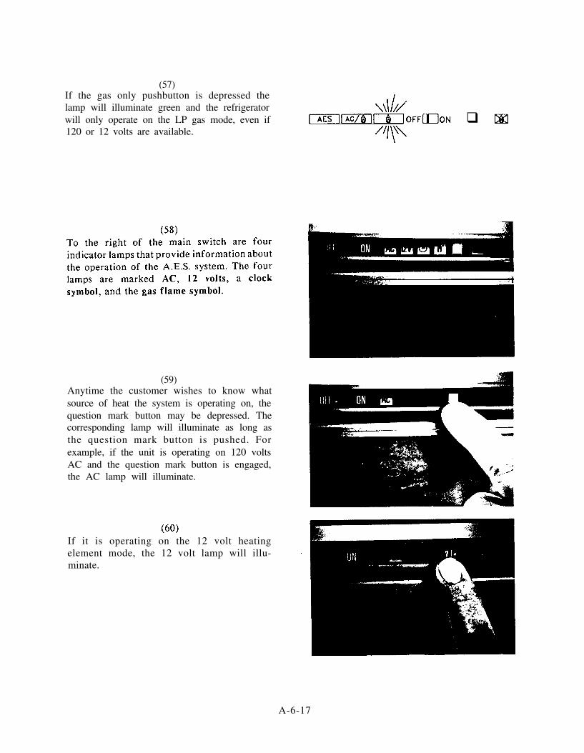
(57)If the gas only pushbutton is depressed thelamp will illuminate green and the refrigeratorwill only operate on the LP gas mode, even if q 120 or 12 volts are available.
(59)Anytime the customer wishes to know whatsource of heat the system is operating on, thequestion mark button may be depressed. Thecorresponding lamp will illuminate as long asthe question mark button is pushed. Forexample, if the unit is operating on 120 voltsAC and the question mark button is engaged,the AC lamp will illuminate.
If it is operating on the 12 volt heatingelement mode, the 12 volt lamp will illu-minate.
A-6-17
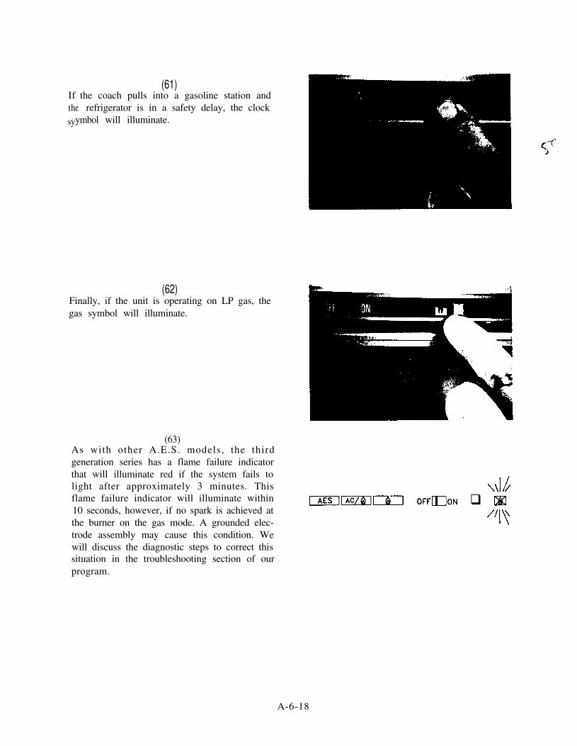
If the coach pulls into a gasoline station andthe refrigerator is in a safety delay, the clocksyymbol will illuminate.
(61)
(62)Finally, if the unit is operating on LP gas, thegas symbol will illuminate.
(63)As with other A.E.S. models, the thirdgeneration series has a flame failure indicatorthat will illuminate red if the system fails tolight after approximately 3 minutes. Thisflame failure indicator will illuminate within10 seconds, however, if no spark is achieved atthe burner on the gas mode. A grounded elec-trode assembly may cause this condition. Wewill discuss the diagnostic steps to correct thissituation in the troubleshooting section of ourprogram.
q
A-6-18

(64)Another significant change in the thirdgeneration A.E.S. system is how the 12 voltheating element mode operates. As with thefirst and second generation series, the 12 voltheating element circuit is energized by theignition lock terminal. This terminal receivesits DC voltage from a wire that runs from therun side of the vehicle’s ignition switch to therefrigerator’s ignition lock terminal. Thisallows the 12 volt heating element to be energized only when the RV is traveling downthe road.
(65) TAG LINE ENERGIZEDWhen the ignition lock terminal is energizedby the ignition key, the printed circuit boardmust see at least 13.3 volts DC for a period of40 seconds before the system will activate the12 volt DC heating element.
VOLTAGE ---) 13.3 V.D.C.(FOR 40 SEC. MIN.)
12V ELEMENTENERGIZES
(66)If 13.3 volts is not achieved in this time frame,the electronics will light the LP gas burner andthe refrigerator will operate on the LP gasmode.
LOWER THAN 13.3 V.D.C. =
L.P. GASOPERATION
A-6-19

(67)If at any time while traveling the DC voltagereaches the approximate 13.3 threshold, the LPgas flame will shut off and the 12 volt heatingelement will energize, continuing normaloperation on the 12 volt mode.
(68)The voltage to the terminal block iscontinuously monitored by the printed circuitboard, while the RV is traveling. Let’s take alook at a couple of ways this battery protectionsystem can be beneficial to the customer. First,suppose a customer has a weak or underratedalternator installed in the RV that is equippedwith an RM3801. As the vehicle’s ignition isturned on, the ignition lock terminal isenergized by 12 volts, but because of the weakalternator, the printed circuit board can neversee the 13.3 volts at the terminal block that isneeded to energize the 12 volt heating element.So, the refrigerator will light and stay on thegas mode while the RV is traveling.
(69)After a few hours of driving, the customerpulls into a gasoline station to refuel thevehicle. Even though the system is operatingon the gas mode, as soon as the ignition key isturned off, the LP gas flame shuts off and thesystem initiates an approximate 25 minute timedelay mode. This allows the customer to stopand refuel the coach without turning the unitoff. As long as the ignition lock terminal isenergized with 12 volts by the ignition switch,the system will always go into a safety delaywhen the ignition key is turned off. This willprevent an open flame at the burner whenrefueling.
TAG LINE ENERGIZED
VOLTAGE -+ 13.3 V.D.C.(FOR 40 SEC. MIN.)
12V ELEMENTENERGIZES
TAG LINE ENERGIZED
VOLTAGE 13.3 V.D.C.(FOR 40 SEC. MIN.)
12V ELEMENTENERGIZES
LOWER THAN 13.3 V.D.C. q
L.P. GASOPERATION
,,’
VOLTAGE + s”i”C:C~,N.)
12V ELEMENTENERGIZES
LOWER THAN 13.3 V.D.C. =L.P. GAS
OPERATION
::..::.::.:: ..:.,.:::,.::..IGNITION KEY
TURNED DFF =
25 MIN.SAFETY DELAY
A-6-20

(70) TAG LINE ENERGIZEDSecondly, suppose a customer has a properlywired RM3801 in a motor home that isequipped with a fully functional alternator.After the ignition key is turned on, the printedcircuit board determines that at least 13.3 voltsis available at the terminal block, so the 12volt heating element engages.
VOLTAGE ---) 13.3 V.D.C.(FOR 40 SEC. MIN.)
12V ELEMENTENERGIZES
(71)When the customer leaves on the trip it is ahot, muggy night so the vehicle’s headlamps aswell as the dash air conditioning system isturned on. After a few minutes of driving itbegins to rain, so the windshield wipers arealso turned on. With all of these componentsoperating in the coach, the alternator hasdifficulty keeping up with the demand of thetotal coach load and the house battery beginsto drain. As soon as the printed circuit boardsees that the battery voltage going to therefrigerator has dropped to approximatelyvolts, the electronic circuitry will shut off the12 volt DC heating element to protect thehouse battery, At this time, an approximate 25minute delay cycle will be in progress.
LOWER THAN 11 V.D.C. =
HEATINGELEMENT
OFF
SAFETY DELAY
(72)If the battery voltage remains low after thedelay cycle, the automatic controls will lightthe refrigerator on the LP gas mode and stayon the gas mode until the printed circuit boardsees approximately 13.3 volts DC to theterminal block. LOWER THAN 13.3 V.D.C.
FOR 25 MIN. OR MORE q
L.P. GASOPERATION
A-6-21

(73)If at any time the battery regains itself to theapproximate 13.3 volt threshold during the 12volt cooling mode, the controls will againreengage the 12 volt DC heating element.
(74)As with the first and second generation seriesA.E.S. models, any time the battery voltage tothe terminal block drops to approximately 9.5volts DC, the refrigerator will switch to anonthermostatically regulated gas flame toinsure the unit will still provide cooling forthe customer. As a low battery indication, thegreen mode switch indicator lamp will shutcompletely off during the voltage drop.
(75)Before we take a look at diagnostic proceduresfor the A.E.S. refrigerators, let’s discuss theexternal fuel and power source requirementsfor proper operation. 120 VOLT AC POWER- the refrigerator is equipped with a threeprong, grounded AC plug for protectionagainst shock hazards and should be pluggedinto a proper ly grounded three prongreceptacle. Do not cut or remove thegrounding prong from this plug.
(76)The power cord should be routed to avoidcoming in contact with areas that become hotduring normal operation or areas that couldcreate a safety hazard. These areas include theburner cover, flue cover or the manual gasshut-off valve knob.
TAG LINE ENERGIZED
VOLTAGE 13.3 V.D.C.(FOR 40 SEC. MIN.)
12V ELEMENTENERGIZES
LOWON GAS VOLTAGE
FAILURE / O F F
SOLID FLASHING NO LIGHTGREEN RED
A-6-22

(77)For proper cooling on the AC mode, the ACvoltage to the refrigerator should not varymore than 10 percent from the voltage ratingon the heating element. Heating elements usedin Dometic refrigerators could have a ratedvoltage of 110 volts, 115 volts or 120 volts AC.Because of this, the power requirements foreach differently rated heating element willvary. For example, if a heating element israted for 100 volts, the acceptable power rangewould be between 99 to 121 volts AC. If anelement is rated for 115 volts, the acceptablepower range would be between 103.5 to 126.5volts AC. If the heater is rated for 120 volts,the acceptable AC power range would bebetween 108 to 132 volts AC.
(see page A-6-24)
(78)Refer to the voltage rating stamped on theheating element to determine if the voltage tothe refrigerator is adequate to operate thesystem properly.
(79)12 VOLT WIRING - for any A.E.S. to operateon any heat source the refrigerator mustreceive a 12 volt supply to the positive andnegative connections on the terminal block atall times. The refrigerator must be connecteddirectly to the house battery with 2 wires ofadequate capacity to avoid a voltage drop.
A-6-23

RATED VOLTAGE ONHEATING ELEMENT AC OPERATIONAL RANGE
110V 99 - 121VAC115V 103.5 - 126.5V AC120v 108 - 132VAC
A-6-24

As seen in the chart on page A-6-26, thegauge of wire required to the positive andnegative connections on the terminal block willdepend on the size of the refrigerator and thelength of wire run from the house battery tothe terminal block. This 12 volt circuit must befused. The maximum fuse size should be 30amps.
Be sure that a separate negative wire leadcoming directly from the battery is connectedto the negative terminal on the refrigeratorand that a frame or chassis ground is not usedas a substitute. Be certain that no other 12 voltequipment or lighting is connected to therefrigerator circuit. For the refrigerator tooperate properly on any heat source, theterminal block must receive between 10.5 and13.5 volts DC.
(82)If any other technical information is neededwhen diagnosing or repairing any 12 voltcircuit problem the technical data sheet cangive you other beneficial information, such asheater wattages and amperage draws. (Referalso to Service Bulletin 28).
(83)Please note that if a battery converter is usedas the sole DC power source, the refrigeratorwill not operate properly. The pulsating DCpower created by the converter will confusethe electronic circuitry into erratic operationand possible printed circuit board failure.When a battery converter is utilized in theinstallation, the circuit must be wired as shownin the diagram on page A-6-29.
(see page A-6-26)
(see page A-6-27)
(see page A-6-28)
(see page A-6-29)
A-6-25

RECOMMENDED WIRE GAUGE AND LENGTH FORAES MODEL REFRIGERATORS
AWG Maximum Wire Length
RM3500 RM3600 RM3800RM663 RM763 RM1303
10 19 ft. 13 ft. N/A8 31 ft. 22 ft. 19 ft.6 49 ft. 34 ft. 31 ft.
1st and 2nd generation series models.
AWG
108
Maximum Wire Length
RM3601 RM380117 ft. 17 ft.27 ft. 27 ft.
3rd generation models.
A-6-26

REFRIGERATORTERMINAL BLOCK
POSITIVE NEGATIVE
A-6-27

AES REFRIGERATOR TECHNICAL DATA1ST GENERATION MODELS
MODEL COOLING UNITNO. PART NO.
RM 663 928 3609 00/7
CORRECTFLOW A/C Heater
ORIFICE SIZE & METER BTU INPUT HEATER ELEMENT SPECS. AC DC Resistance Electric Thermostat Gas ThermostatPART NO. READING BURNER Watt/Volts , Part No. AMPS AMPS IN OHM’S PART NO. PART NO.
52 (200 7419 18/3) .48 1226 210/120 0173738 048 1.8 17.5 67 292 05210012 0.522 00/2
2ND GENERATION MODELS
MODELNO.
RM 3500
COOLING UNITPART NO.
293 4701 09/1
CORRECTFLOW A/C Heater
ORIFICE SIZE & METER BTU INPUT HEATER ELEMENT SPECS. AC DC Resistance Electric Thermostat Gas ThermostatPART NO. READING BURNER Watt/Volt. , Put No. AMPS AMPS IN OHM’S PART NO. PART NO.
3 9 (200 7419 IS/Q) .48 1000 185/120 0173738 063 1.5 16.4 80 200 7712 OS/S 200 7712 03 /3 ,
RM3600 293 4801 0 9 / 9 5 3 (200 7419 19/l) .52 1300 295/120 0173754 046 2.5 17.9 48 293 0523 01/0
RM3800 293 4901 09 /7 58 (200 741Q 21/7 .60 1500 325/120 0173742 081 2.7 17.9 44 293 0523 01/0
3RD GENERATION MODELS
RM 3601 293 4801 09/9 53 (2W 7419 19/l) .52 1300 295/120 0175754 045 2.5 17.9 48 293 0814 01/3 293 0814 01/3
RM 2801 293 4901 0 9 / 7 68 (200 7419 21/7) .60 1500 325/120 0173742081 2.7 17.0 44 293 0814 01/3 293 0814 01/3
A-6-28

PROPER WIRING OF AN AES WITH A BATTERY CONVERTER
REFRIGERATORTERMINAL BLOCK
0-CONVERTER
0+ 12V BATTERY
A-6-29

(84)If the 12 volt circuit is wired as shown on pageA-6-31, the battery will not be able toproperly filter the converter voltage. Thiscould cause erratic operation or prematureprinted circuit board failure. Remember, thepositive and negative DC power leads to therefrigerator must come directly from thebattery.
LP GAS SUPPLY - A.E.S. refrigerators useliquid petroleum gas (propane) that is adjustedto provide a pressure of 11 inches watercolumn pressure at the refrigerator test plug;with at least l/2 of the coach’s LP gas load inoperation.
(86)A periodic leak check of all the LP gasconnections is recommended using anoncorrosive type of bubble so lu t ion .WARNING: DO NOT use a flame to check forleaks.
(87)If, during the lighting sequence, attempts tostart the LP gas flame are not successful, makesure the LP tank is not empty. Also, insurethat all of the manual shut-off valves areturned on and are in the open position.
(see page A-6-31)
A-6-30

TERMINALSTRIP
(Buss Bar)
REFRIGERATOR
\TERMINAL BLOCK
UNACCEPTABLE CONNECTION FOR AN AES
A - 6 - 3 1

(88)If the refrigerator has not been used for sometime or if the main supply tanks have justbeen refilled, air may be trapped in the LPsupply lines. To purge this air from the linesmay require resetting the refrigerator two orthree times before normal gas operation willbegin.
(89)We will now take a look at the troubleshootingprocedures for the A.E.S. models RM3801 andRM3601. For diagnostic information on thefirst and second generation series models, referto Service Bulletin No. 46. (See pages A-9- 1 toA- 10-2).
(90)We will cover each of the four most commonservice problems separately and illustrate thesteps needed to diagnose and repair therefrigerator properly. These situations include:NO operation, meaning the refrigerator willnot operate on 120 volts, 12 volts or LP gas,NO 120 volt AC operation, 12 volt DCoperation, and NO LP gas operation.
(91)NO OPERATION. Whenever an A.E.S.refrigerator fails to operate on any heat sourcewe must diagnose the components and circuitsthat are utilized by every heat source.
DIAGNOSTIC AREAS
1. NO OPERATION
2. NO 120 V.A.C. OPERATION
3. NO 12 V.D.C. OPERATION
4. NO L.P. GAS OPERATION
NO OPERATION
A-6-32

(92)The first step to take is to insure that the 12volt DC power supply and it’s associatedwiring is providing the proper DC voltage tooperate the electronic circuitry correctly.Remember without a proper DC hookup to therefrigerator’s terminal block, the unit will notoperate on any heat source.
(93)Check the incoming battery voltage at theterminal block to insure that between 10.5 to13.5 volts are present and that the correct wirepolarity has been utilized in the installation.
(94)Second, make sure the negative battery leadconnects to the negative connection on theterminal block and the positive battery leadconnects to the positive connection on theterminal block. As we stated earlier in theprogram, check to see that the 12 voltrefrigerator circuit is wired as shown in thisdiagram. Correct this if necessary. (Also seepage A-6-27).
(95)Third, inspect that the proper gauge wire hasbeen used as illustrated in the chart shownhere. (Also see page A-6-26)
REFRIGERATORTERMINAL BLOCK
RECOMMENDED WIRE GAUGE AND LENGTH FORAES MODEL REFRIGERATORS
AWG Wire Length
RM3500 RM3600 RM3800
10 19 ft. 13 ft. N/A8 31 ft. 22 h. 19 ft.6 49 ft. 34 ft. 31 ft.
1st and 2nd generation “ti models
8 27 ft. 27 ft.
3rd generation models.
A-6-33

(96)Check the 3 amp. DC fuse at the rear pro-tection cover. If it is blown, check the 12 voltwiring on the coach and refrigerator fordamage and repair, or replace if needed. Whenreplacing the 3 amp. fuse do not substitutewith an automotive quick blow type fuse, as itcould needlessly blow during normal refrig-erator operation.
(97)The next component to check in our diagnosisis the thermostat. If the thermostat orthermostat leads are defective the refrigeratorwill not operate on any heat source, as all heatsources are directed through this component innormal operation.
(98)If it is believed the thermostat circuit isdefective, first inspect the condition of thethermostat cable and see that it is correctlyconnected to the printed circuit board.
(99)Next, gain access to the interior lightthermostat assembly by removing themounting screw and taking off the plasticcover to expose the thermostat and wireconnections.
A-6-34

Remove the two thermostat leads and placethem together using electrical tape. This willby-pass the thermostat from the electricalcircuit. If the refrigerator begins operatingwhen the leads are by-passed, the thermostatis defective and must be replaced. Be carefulnot to touch any surrounding metal parts withthe thermostat lead ends when performing thisprocedure, as this will needlessly blow the 3amp. protection fuse.
(101)The main switch contains many differentfunctions in the A.E.S. refrigerators, whichincludes controlling the heat sources. In thissection we will discuss the troubleshootingprocedures for the entire switch functions,,including the mode switch lamps as well as thefunction lamps. Before gaining access to theswitch, visually inspect the switch cable forany cuts or shorts. Check to see that the plugconnector is properly inserted into the printedcircuit board connection.
(102)Next, disconnect the positive and negativebattery leads from the terminal block. All ofour diagnosis on the switch will be made withcontinuity or ohm’s resistance. Failure todisconnect the DC power supply duringdiagnosis could result in switch failure if itinadvertently touches metal.
A-4-35

(103)Refer to the RM3801 switch diagnosistroubleshooting sect ion of the A.E.S.Diagnostic Manual for a detailed explanationon how to troubleshoot these switches. (Seepages A-8-l to A-8-5)
(104)The next component to diagnose is thesolenoid valve’s internal winding. The A.E.S.control system uses the solenoid winding toprovide a ground circuit to the printed circuitboard for all modes of operation. If thesolenoid winding is defective, the refrigeratorwill not operate on any heat source.
(105)To check the solenoid winding, remove allpower sources from the refrigerator, AC andDC and unplug the connector at the solenoidby pulling firmly outward.
Measure the resistance value across the upperand lower terminals on the valve assembly.The proper valve should be 20 ohms withtolerance range of 10 percent. Values outsidethe tolerance range or no ohms reading wouldindicate a defective solenoid valve winding.
A-6-36

(107)As in all of our troubleshooting steps, theprinted circuit board is the last component tocheck for a failure. Insure that all of theconnections on the board are clean and areinserted in their proper locations beforeattempting to determine if the printed circuitboard is at fault.
(108)Many times when a circuit board failure isnoticed it will be visible as a burned section onthe board. Determine the cause of the boardfailure by referring to SERVICE BULLETINR56-7A (pages A- 1 l-3 to A- 11-5) and correctthe external problem before replacing thecircuit board. FAILURE TO DO SO COULDR E S U L T I N R E P E A T E D B O A R DPROBLEMS.
(109)NO 120 VOLT AC OPERATION. To beginour diagnosis of the 120 volt mode, determineif the house battery and its associated wiringis adequate to operate the electronic circuitryproperly, as we discussed in the “no operation”section of our program.
NO 120 V.A.C. OPERATION
Also, determine if the AC voltage to therefrigerator is within 10 percent of the ratedstamped voltage on the heating element.Correct any wiring or voltage problems asneeded to provide an adequate power supply tothe refrigerator.
A-6-37

(111)After we have determined that the correct ACand DC power is available to the refrigerator,we need to diagnose the 120 volt heatingelement. Generally speaking, when a 120 voltheating element does not deliver the properamount of BTU’s, it does not heat up at all. Insome cases, however, a heating element maybe just partially defective. In either case, thetroubleshooting steps are the same todetermine if the element is at fault.
(112)Remove the 120 volt power cord from the walloutlet and gain access to the heater leads onthe printed circuit hoard by removing thenecessary protection covers.
(113)Remove the leads and measure for properresistance across the two heater leads with aproperly calibrated ohm meter. Refer toS E R V I C E B U L L E T I N 2 8 o r t h e AESTECHNICAL DATA SHEET on page A-6-28to determine if the ohms value obtained is theproper reading for the model you are workingon.
(114)Shown here is an example of the informationavailable in this bulletin. As with most of ourelectrical checks, an acceptable tolerance rangeon the ohms valve obtained is 10 percent. Ifthe ohms value on the heating element doesnot fall within the necessary tolerances, theelement is defective and must be replaced.
A-6-38
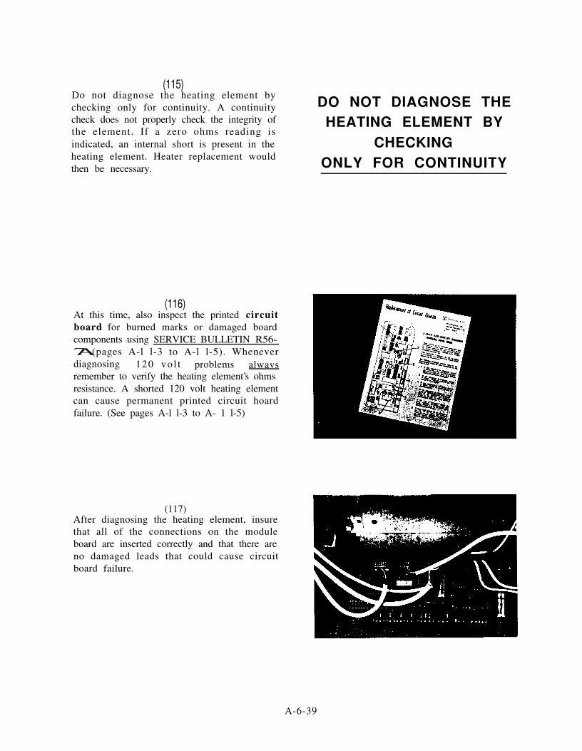
(115)Do not diagnose the heating element bychecking only for continuity. A continuity DO NOT DIAGNOSE THEcheck does not properly check the integrity ofthe element. If a zero ohms reading isindicated, an internal short is present in theheating element. Heater replacement wouldthen be necessary.
HEATING ELEMENT BYCHECKING
ONLY FOR CONTINUITY
(116)At this time, also inspect the printed circuitboard for burned marks or damaged boardcomponents using SERVICE BULLETIN R56-7A (pages A-l l-3 to A-l l-5). Wheneverdiagnosing 120 vo l t problems alwavsremember to verify the heating element’s ohmsresistance. A shorted 120 volt heating elementcan cause permanent printed circuit hoardfailure. (See pages A-l l-3 to A- 1 l-5)
(117)After diagnosing the heating element, insurethat all of the connections on the moduleboard are inserted correctly and that there areno damaged leads that could cause circuitboard failure.
A-6-39

(118)Next, diagnose the switch by following theswitch diagnosis section of the A.E.S. manualwhich we have previously discussed. As a finalcheck in our diagnosis of the 120 volt circuit,visually inspect the refrigerator power cord. Ifnecessary check the cord end to end forcontinuity on the ground black and whitewires that make up the power cord. If nocontinuity is indicated on one or more of thepower cord wires replace the power cord.During this diagnostic step be sure that thepower cord leads are firmly connected to theAC terminal block.
(119)NO 12 VOLT DC OPERATION. As wementioned earlier in the program, the ignitionlock terminal houses the wire connection thatcontrols the 12 volt heating element circuit andthe 25 minute delay cycle.
The wire from this terminal should be routeddirectly to the run side of the vehicle’s ignitionswitch. This will provide DC voltage to theignition lock terminal only when the vehicle isin motion. It also allows the vehicle’s alternatorto keep the house battery charged andeliminates a possible dead battery due to thecustomer forgetting to switch off therefrigerator. Whenever the ignition key isturned off, the electronic control system willinitiate a 25 minute delay cycle. When thevehicle’s ignition is turned back on the systemwill re-energize the 12 volt DC circuit. Theignition lock wire, which is commonlyreferred to as the “tag line”, should be a wiresize of at least 16 gauge. The amperagedemands from the element are handled by thepositive and negative leads of the terminalblock, which necessitates the need for largerwire gauge requirements.
NO 12 V.D.C. OPERATION
A-6-40

(121)When beginning to diagnose the heatingelement c i rcui t , keep in mind that anapproximate DC voltage of 13.3 to theterminal block is required to engage to 12 voltDC heating element. Any voltage lower than13.3 will prevent DC operation and therefrigerator will operate on the LP gas mode.
(122)After verifying that the 12 volt battery circuitis wired properly and that the proper gaugewire size has been utilized. Check the DCvoltage at the terminal block to insure that atleast 13.3 volts is available to energize the 12volt heating element.
(123)If proper voltage is available at the terminalblock and the refrigerator is still notoperational on 12 volts, the DC relay needs tobe diagnosed.
(124)Gain access to the relay and make sure theignition switch is turned to the off positionand voltage is not present at the ignition lockterminal. DC voltage should be presentbetween terminals 85 and 30 on the relay. Ifvoltage is not present, recheck all 12 voltconnections. Pay close attention to theconnections on the positive terminal, as this iswhere the 30 terminal attaches.
A-6-41

(125)DC voltage should not be present betweenterminals 85 and 87 on the relay when theignition key is disengaged. If voltage is presentat these terminals the relay is defective andmust be replaced.
Next, energize the vehicle’s ignition switchand check for voltage between terminals 85and 86 on the relay. Voltage should be present.If no voltage is present between theseterminals, other components and connectionsare suspect, such as the switch, thermostat orcircuit board.
As our final test of the relay, check forvoltage between terminal 85 and 87. If novoltage is present the relay is defective andmust be replaced.
(128)A defective 12 volt heating element will alsocause the refrigerator not to operate on the DCmode. Disconnect the heater lead that attachesto the 87 terminal on the DC relay and thelead that attaches to the refrigerator groundingstrip.
A-6-42

(129)Measure resistance across the leads as outlinedearlier in our program for the 120 volt heatingelement. The reading, however, will bedifferent from the AC heating element. Forthe models RM3601 and RM3801 the ohmsresistance should be .67, with a tolerance rangeof 10 percent. If there is no ohms reading or areading outside the 10 percent tolerance range,the heater is defective and must be replaced.Please note that it will take a very precise ohmmeter to accurately read this measurement.
(130)A malfunctioning switch assembly may alsoaffect the DC mode. As outlined in previousdiagnostic steps in our program, diagnose theswitch for proper operation. In our final checkof the 12 volt cooling system, check all wiringharnesses and leads for shorts or opens. Ifnecessary use an ohm meter, end to end, onthe suspect leads.
(131)NO LP GAS OPERATION NO LP GAS OPERATION
A-6-43

(132)To diagnose a gas operational problem be surethe refrigerator is in the A.E.S. mode.
(133)The first diagnostic step is to be sure there areproper DC volts at the terminal block, inaccordance with the previous explanation onthe DC power source. (See pages A-6-33through A-6-34, paragraphs 92-96)
(134)Next, check to be sure the 120 volt power cordto the refrigerator is unplugged from thereceptacle. Then check for voltage at theterminal block between the ignition lockterminal and the negative terminal. If anyvoltage is present you will not be able to havegas operation. These must be corrected beforeany further checks can be done.
(135)Now that we have proper DC voltage, no 120volt and the ignition lock is not energized, wecan start to diagnose the gas system. Be surethe manual gas shut-off valve is in the offposition. Remove the twelve (12) millimetergas test port plug and install a l/8 NPT fittingin its place.
A-6-44

(136)Now hook up a manometer to the test fittingand leave it in place until all checks have beenmade for gas operation. Turn the shut-offvalve and refrigerator on and check for a gaspressure reading. A correct reading would beeleven (11) inches water column pressure. Ifneeded, adjust the main gas regulator at theLP gas tanks.
(137)If you do not obtain any pressure, you mustcheck the electric solenoid. To diagnose theelectric solenoid windings, do the ohmsresistance check that was discussed earlier inthis program. (See page A-6-36, paragraph106)
(138)Another check is to disconnect the electricsolenoid wires. Supply DC voltage to theBOTTOM terminal of the electric solenoid bymeans of a temnorarv jumper wire from thepositive terminal on the terminal block.
A-6-45

(139)You should hear a sharp click from thesolenoid and now obtain a gas pressurereading. If these results are not realized thesolenoid is defective and must be replaced.
(140)If these results are correct you must nextcheck the wires that connect to the solenoidvoltage. The results should be close to thevoltage coming to the appliance.
(141)We will now check the igniter-reigniterassembly. First turn the unit on and check forvoltage between the positive and groundterminals on the igniter. If you obtain a DCvoltage reading, the igniter is receiving power.
(142)If you do not obtain a reading, move the meterprobe from the ground terminal of the igniterto the negative terminal on the terminal block.If you now have a reading on the meter andyou did not at the igniter, you have a problemin the ground circuit. If you obtained areading on both the tests, the igniter isreceiving power.
A-6-46

(143)The next diagnostic step is to turn the unit offand then remove the high voltage wire fromthe igniter. When the unit is turned on youshould hear a sharp clicking sound from theigniter. If no sound is detected, replace theigniter. When sound is present the igniter isgood.
(144)If the igniter checks good and there still is nospark at the electrode, you must check thehigh voltage wire and electrode. Make a visualcheck of the high voltage wire for any defectsor broken insulation on the wire that couldallow the high voltage to go to ground. Also,check the wire that has been disconnected ateach end for continuity.
(145)The electrode spark gap must be set at threesixteenths (3/16) of an inch to provide aproper spark. The spark gap is the distancebetween the burner and the tip of theelectrode.
Burne
(146)You would next check the electrode for anyvisual cracks or breaks on the ceramic portion.If you have a good igniter and high voltagewire and still do not have spark at the tip ofthe electrode, replace the electrode.
A-6-47
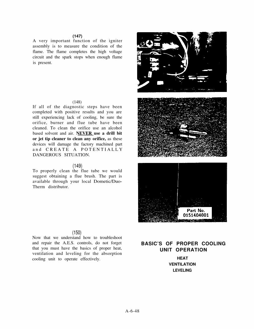
(147)A very important function of the igniterassembly is to measure the condition of theflame. The flame completes the high voltagecircuit and the spark stops when enough flameis present.
(148)If all of the diagnostic steps have beencompleted with positive results and you arestill experiencing lack of cooling, be sure theorifice, burner and flue tube have beencleaned. To clean the orifice use an alcoholbased solvent and air. NEVER use a drill bitor jet tip cleaner to clean any orifice, as thesedevices will damage the factory machined parta n d C R E A T E A P O T E N T I A L L YDANGEROUS SITUATION.
(149)To properly clean the flue tube we wouldsuggest obtaining a flue brush. The part isavailable through your local Dometic/Duo-Therm distributor.
(150)Now that we understand how to troubleshootand repair the A.E.S. controls, do not forgetthat you must have the basics of proper heat,ventilation and leveling for the absorptioncooling unit to operate effectively.
BASIC’S OF PROPER COOLINGUNIT OPERATION
HEATVENTILATION
LEVELING
A-6-48

(151)If you require additional service assistance thebasic requirements for the cooling unitoperation or the A.E.S. control system, pleaserefer to our manual refrigeration or A.E.S.training manuals. For day-to-day technicalservice assistance contact the technical servicedepartment.
(152)You are an essential part of a team thatcontributes greatly to the successful future ofthe RV industry, your dealership and TheDometic Corporation.
A-6-49

AES Refrigerator
GLOSSARY OF TERMS
A E S Automatic Energy Selector Refrigerators. First introduced in 1983, the 1st and 2nd generation series will automatically select the available heat source for operation (12OV AC, 12V DC or LP gas)by simply turning the refrigerator to the “ON” position. The 3rd generation series have the addedflexibility of being utilized in three (3) individual selector switches, the refrigerator can be operatedas a full AES, on 120V and LP gas only or gas operation only.
AUTOMATIC IGNITER/REIGNITER - An electronic 12V DC device that directly replaces the piezolighter, found on manually controlled models for several years. When 12V DC is supplied to theigniter it produces a high voltage that is supplied through the electrode cable and electrode whichproduces a spark at the burner to light the air/gas mixture. An added benefit of this system is that12V is supplied continuously to the igniter during the gas mode. If the flame should blow out, theigniter will re-engage and relight the flame at the burner. An additional function of the igniter is thatit produces an increased DC voltage that ultimately opens the solenoid valve.
BURNER - A slotted metal tube located just below the flue tube on the cooling unit, an integral partof the gas system. This is where the igniter spark occurs which produces LP gas flame at the burnerthat produces the necessary heat to initiate the cooling process at the cooling unit. Both orifice andburner should be cleaned periodically to maintain proper cooling capabilities of the refrigerator.
DELAY CYCLE - If refrigerator is wired to the installation according to Dometic’s specifications, everytime the ignition switch is turned to the “OFF” position, following 12V cooling operation, a safetydelay cycle begins. For approximately 25 minutes the refrigerator will remain off and will not selectLP gas operation. This is to insure there will not be an open flame at the burner while the customerrefuels the R.V.. The 120V cooling mode is not affected by the delay cycle. Anytime the refrigeratorreceives 120V at the power cord, the unit will operate on the AC mode. On the 3rd generation seriesmodels this safety delay cycle has been incorporated into the controls to protect the 12V DC coolingcircuit as well. If battery voltage to the terminal block drops below 11V DC when the refrigeratoris operating in the 12V DC mode, the controls will disengage the 12V heating element and go intoa delay cycle. As soon as battery voltage regains proper voltage (13.3V DC) the delay cycle willdiscontinue and refrigerator will operate on 12V DC cooling mode. If voltage does not regain itselfafter approximately 25 minutes, the controls will select gas operation to insure proper cooling. Thisdelay cycle may be over-run (see Off/On Procedure, Item 24).
A-7-1

AES Refrieerator GLOSSARY OF TERMS continued
ELECTRODE - The angular piece of metal located just above the burner that is connected to thehigh voltage cable. High voltage “jumps” the air gap between electrode and burner, and createsthe sparking seen at the burner. This circuit is grounded by the gas flame which stops the sparkingproduced by the igniter. For igniter/high voltage cable/electrode assemblies to operate correctly,the electrode must be positioned properly. The air gap distance between electrode and burnershould measure approximately 3 /16"
GAS PREVENTION SAFETY DEVICE - The AES has a safety circuit that will prevent sparkingand gas ignition on the gas mode if one of the following conditions occur:
A. Printed circuit board failureB. Igniter failureC. No voltage is present at positive and negative
connections at the terminal block
This safety circuit is designed to insure that LP gas will not accumulate at the burner due to a partfailure.
HEAT INPUT - One (1) of three (3) requirements for proper operation with absorption refrigerators.This specification is critical to maintain proper cooling properties of the cooling unit. With toolittle heat at heating element or burner, the ammonia in the cooling unit will not vaporize (boiloff) properly and a lack of cooling will result. An excessive amount of heat to the cooling unit willcause the water, as well as ammonia, to vaporize, causing the cooling process to stop. Since as littleas 25 BTU’s input can dramatically affect operation of the cooling unit, it is NOT recommendedto substitute heating element sizes or burner orifice values. Whenever diagnosing heat inputproblems, refer to Service Bulletin No. 28 or the AES Technical Data Sheet on page A-6-28.
HEATING ELEMENTS - Self-contained heat generating devices operating off either AC or D Cvoltage that supplies heat to generator section of the cooling unit.
HIGH VOLTAGE ELECTRODE CABLE - Cable that transmits high voltage, produced by theigniter, and sends it to the electrode. High voltage from the igniter results in sparking at theburner assembly which lights the air/gas mixture at the burner. This cable should always bedisconnected when diagnosing the igniter. If the cable is shorted to ground the result will be nospark on LP gas operation.
A-7-2

AES Refrigerator GLOSSARY OF TERMS continued
INDICATOR LAMP(S) - Consisting of light emitting diode(s) (L.E.D.) the 1st and 2nd generationseries refrigerators will illuminate green when main switch is turned to the “ON” position. Ifrefrigerator fails to ignite after trial for ignition sequence (2-3 minutes), the green L.E.D. willshut off and a red L.E.D. will flash on and off, indicating a flame failure. If the incoming batteryvoltage to the terminal block drops to approximately 9.5V DC, the indication lamp will shut offindicating a low voltage situation. The 3rd generation series utilizes three (3) separate greenL.E.D.‘s that are located behind the mode selector pushbuttons. If this series goes into flamefailure, a separate L.E.D. will illuminate orange to indicate this condition.
LEVELING - One of three (3) requirements for proper operation with absorption refrigerators. Theabsorption design utilizes no mechanical pumps or compressors to circulate the refrigerant withinthe system, so proper leveling must be maintained to provide the correct refrigerant flow. Withoutproper leveling, refrigerant within the cooling unit will collect and stagnate at certain areas.Without proper refrigerant flow, the cooling process will stop. Cooling units that utilize an exposedsiphon pump tube at the generator section (units with square boiler boxes) require a preciseleveling check. To properly level these units a spirit (bubble) level is placed on the floor of thefreezer compartment. To insure operation with the refrigerator when the coach is positioned ina stationary (standing) manner, the bubble must be at least 3/4 inside the central ring.
Important: Permanent damage can result to the square boiler box units if proper leveling is notmaintained. In recent years Dometic has engineered a new type of cooling unit that utilizes anenclosed pump tube surrounded by a weak ammonia solution to protect the assembly. These unitsare evidenced by a circular boiler box cover. To insure proper leveling in these units, the vehicleneeds to be leveled only so it is comfortable to live in (no noticeable sloping of floor or walls).
When the vehicle is moving leveling is not critical as the rolling and pitching movement of thevehicle will pass to either side of level, keeping the ammonia from accumulating in the piping.
LP GAS TRIAL FOR IGNITION (Lockout) - Similar to a DSI R.V. furnace, AES refrigeratorsincorporate a timed lighting sequence that is controlled by the printed circuit board. When thecontrols select LP gas operation, high voltage sparking from igniter and LP gas solenoid areenergized. Normally in just a few seconds spark will ignite air/fuel mixture at the burner andremain burning until thermostat is satisfied or refrigerator is turned off. If there is air in the gasline, or the R.V. rig has not been used for a long period of time, this lighting procedure may takeup to 2 to 3 minutes to establish a flame. For this reason the AES refrigerator will attempt to lightthe refrigerator for approximately 3 minutes. If after this timed sequence the refrigerator fails toestablish a flame, the igniter and solenoid valve will disengage and no longer attempt to light theburner. This condition is referred to as lockout. To let the customer know that the refrigerator hasgone into lockout, on the 1st and 2nd generation series models, a red L.E.D. will “flash” on thecontrol strip on refrigerator exterior. On 3rd generation series models an orange flame failureindicator will illuminate to identify this condition. Lighting procedure and flame failure indicatorscan be reset by making an Off/On procedure.
A - 7 - 3

AES Refrigerator GLOSSARY OF TERMS continued
MAIN SWITCH (1st Generation) - A rotary, two (2) position switch used to complete or interruptmain power circuit to the printed circuit board. This switch utilizes an “OFF” and “ON” positiononly. With switch turned “ON” the refrigerator will select and operate on the heat source available.
OFF-ON PROCEDURE - Any time the delay cycle is not desired it may be overridden by turningthe main switch to the “OFF” position, waiting approximately 5 seconds and then turning theswitch back “ON”. This procedure cancels the printed circuit board’s “memory” and refrigeratorwill relight on LP gas within a few seconds.
POLARITY - The property of voltage that causes electrons to flow through a circuit in a certainway. In a 12V DC circuit electrons flow from the negative connection on the battery, through theinterconnecting wiring and circuits, then back to the positive connection on the 12V DC battery.Because of this property, to insure proper operation of the refrigerator, the negative lead, fromthe battery, must be connected to the negative connection on the refrigerator terminal block. Thepositive lead from the battery must be connected to the positive connection on the terminal block.
PRINTED CIRCUIT BOARD (PCB) - Sometimes called a module board, this device controls manyof the operational sequences in the AES refrigerator. The board has three (3) primary functionsincluding:
A. Controlling all heat sources (12OV, 12V & LP gas)B. Monitors incoming battery voltage from terminal blockC. Controls the approximate 25 minute delay cycle from 12V DC operation to LP gas operation.
RELAY. 12V DC - A component controlling the circuit to the 12V DC heating element. Containinga set of normally open contacts, the relay will complete the circuit (by closing contacts) to theheating element when proper voltage is established at the relay. With proper voltage supplied tothe relay, an internal coil is energized which closes the contacts to enable 12V DC heating tooperate.
SWITCH BOARD (CARD) (2nd Generation) - Similar to the rotary switch found on 1st generationAES models. The circuits are housed on a printed circuit “bread” board that includes a slide switchand two (2) indicator L.E.D.‘s. Although appearance and diagnosis of this switch is slightlydifferent from the 1st generation switch, it functions the same in the electrical circuit.
A - 7 - 4

AES Refrigerator GLOSSARY OF TERMS continued
SWITCH/MODE INDICATOR BOARD (3rd Generation) - A more sophisticated version of theswitch board. This switch assembly has three (3) separate pushbutton switches as well as theOn/Off main slide switch. The three (3) pushbutton switches are marked
c l
a n d When the main switch is turned on, the 3rd generation refrigerators will
automatically select the mode, operating very similar to the 1st and 2nd generation series.This mode of operation will be indicated by the button illuminating green. If AC and LP gasonly is desired, the pushbutton may be depressed. pushbutton will illuminateto indicate this mode selection. If gas only operation is desired, the q pushbutton may bedepressed. Regardless of what heat source is available, the refrigerator at this point will onlyoperate on LP gas. Again, the pushbutton will illuminate to indicate this mode selection.If a flame failure occurs, the L.E.D. assembly will illuminate orange at the lens This assembly also provides useful information to indicate what mode of operation theelectronic circuitry has selected. On the switch panel there are four (4) indication lensesmarked q , q , q andl. Whenever it is desired to determine what mode of operation theAES has selected, the small mode indication button q is depressed. While this button isdepressed and the AES circuit has selected the 11OV AC mode, will illuminateyellow. If refrigerator has selected 12V DC operation the q lens will illuminate while modeindication is depressed. The will illuminate yellow if system is in the approximate 25minute delay cycle. Finally, if gas selection has been made, the q lens will illuminate.
TERMINAL BLOCK (MAIN) - The AES utilizes a three (3) section terminal block instead of thetwo (2) section assembly found on 3-way manually controlled refrigerators. The block housesconnections marked positive (+), negative (-) and ignition lock (ign. lock). A wire of proper gaugeis connected from the positive lug on the battery to the positive connection on the terminal block.A similar wire, again of proper gauge, is connected from the negative lug on the battery to thenegative connection on the terminal block. This gives the printed circuit board a power feed toautomatically select the proper heat sources and handles the amperage demands when therefrigerator is operating on 12V DC cooling mode. A minimum 16 gauge wire is connected fromthe run side of the ignition switch to the ignition lock connection on the terminal block. This wireconnection will allow the refrigerator to switch to the 12V DC cooling mode when ignition isturned to the “ON” position. When the ignition key is turned “OFF” (directly after 12V operation)the refrigerator will go into an approximate 25 minute delay cycle (see Delay Cycle).
THERMOCOUPLE - A component connected to solenoid valve, extending above the burner assemblyso tip is in the path of flame when refrigerator is operating on LP gas mode. When heat isgenerated at the tip, the thermocouple will produce a small amount of DC voltage that will keepthe solenoid mechanism open to sustain flame. If the flame should blow out and igniter cannotrelight flame within a few seconds, the tip of the thermocouple will cool, which will interrupt theproduction of voltage that, in turn, will allow the mechanism of the solenoid to close. This willprevent LP gas from accumulating at the burner. The thermocouples used will produce from 14 -30 millivolts DC in normal operation.
A-7-5

AES Refrigerator GLOSSARY OF TERMS continued
THERMO-ELECTRIC SOLENOID VALVE - This device directly replaces the safety valve assemblyfound on the manually controlled refrigerators. When the AES selects LP gas operation, 12V DCis sent to the solenoid which opens the internal valve. This allows gas to flow onto the test plugand burner assemblies. Once flame is lit, DC millivolts, produced by thermocouple, will keep thevalve open. If for any reason the reigniter cannot reestablish flame, the thermocouple will coolwhich will stop production of DC millivolts. At this time the solenoid valve will close preventingLP gas to accumulate at the burner.
THERMOSTAT - Very similar to electric thermostats found on the manually controlled refrigeratormodels. This thermostat operates off 12V DC and regulates the inside refrigerator temperature onall heating modes by making and breaking the heat source circuit to the printed circuit board. Ifthermostat is broken (bellows relaxed) on any AES, the refrigerator will not operate on any heatsource.
VENTILATION - One of the three requirements for proper cooling unit operation. The coach ventsystem must be able to provide a way to direct the hot air produced by the action of the coolingunit out away from the installation of the refrigerator. The refrigerator extracts heat (cooling)from the interior of the refrigerator cabinet and dissipates the heat out through the vent system.The vent area must be free of dead air pockets surrounding the sides and top of the refrigeratorto achieve proper air flow. The smaller size refrigerators utilize a double side wall vent system.Where the incoming air is drawn through the lower vent and the heat is dissipated through theupper vent. The larger size refrigerators use a lower side vent and roof vent to accomplish thesame venting requirements. The size and placement of each of these vents is critical so it isimportant to refer to the specific vent requirements outlined in the installation manual whendiagnosing vent systems.
VOLTAGE MONITORING 12V DC (PCB) - The printed circuit board has the ability to monitorincoming battery voltage to the terminal block. On the 1st and 2nd generation series models, ifbattery voltage drops to approximately 9.5V DC (on 120V & LP gas modes only) the printedcircuit board will electronically “by-pass” the thermostat circuit causing refrigerator to light ongas and stay on continuously regardless of thermostat knob setting. This is to insure the customerwill not lose cooling due to voltage drop. When the voltage drop occurs the green L.E.D. willcompletely shut off to warn customer of low incoming voltage. Third generation series modelshave an even more sophisticated 12V DC monitoring system. These models will not engage the 12VDC heating element circuit until 13.3V DC is detected at the terminal block for approximately 40seconds. If proper voltage (13.3V DC) is not established within 40 seconds the printed circuitboard will select LP gas operation. If the 12V DC circuit to the heating element is initiallycompleted but, due to demands of all DC appliances in the R.V., the DC voltage drops to
A-7-6

AES Refrigerator GLOSSARY OF TERMS continued
approximately 1lV DC, the refrigerator will disengage the 12V heating element and initiate anapproximate delay cycle. (See Delay Cycle). As with the 1st and 2nd generation models, the 3rdgeneration models will stay lit continuously on LP gas mode if voltage drops to approximately 9.5VDC. At this time the mode switch lamp will shut off to let the customer know DC voltage is low.
WIRE GAUGE (Size) - A standardized method of rating the size of wire diameter. In electricalappliances the size of wire is a necessary consideration so the circuits do not experience voltagelosses and the wire can handle the amperage demands of the electrical components. A small gaugewire cannot safely handle the same amperage loads with a voltage drop that a larger gauge wirecan. The smaller the gauge of wire, the larger is its numeral value; the larger the gauge of wire,the smaller is its numerical value. For the refrigerator to operate properly on all modes of heat,refer to wiring size chart to insure the proper size wire has been used in the installation (see pageA-6-26).
A - 7 - 7

AES Refrigerator
CONTINUITY READINGS FOR SWITCH CARD & HARNESS
Model 3801
The following is a list of checks that should be made on the switch card and harness assembly beforereplacing the switch card or wiring harness. These checks are to be done with wiring harnessREMOVED from the printed circuit board.
1. ON-OFF SWITCHA. With the switch in the “ON” position, continuity should be indicated between the yellow
terminal on the 10 pin connector to the orange terminal on the 10 pin connector.
B. With the switch in the “OFF” position, no continuity should be indicated between the yellowterminal on the 10 pin connector to the orange terminal on the 10 pin connector.
C. With the switch in the “OFF” position, continuity should be indicated between the redterminal on the 10 pin connector to the orange terminal on the 10 pin connector.
D. With the switch in the “ON” position, no continuity should be indicated between the redterminal on the 10 pin connector to the orange terminal on the 10 pin connector.
2. AES FUNCTION SWITCHA. With the AES function switch manually depressed, continuity should be indicated between
the blue terminal on the 7 pin connector to the black terminal on the 7 pin connector.
B. With the AES function switch NOT depressed, no continuity should be indicated betweenthe blue terminal on the 7 pin connector to the black terminal on the 7 pin connector.
3. AES FUNCTION LAMPA. Measure resistance between the brown terminal on the 10 pin connector to the brown
terminal on the 7 pin connector. The proper resistance is approximately 65,000 OHMS.
4. AC/GAS FUNCTION SWITCHA. With the AC/GAS function switch manually depressed, continuity should be indicated
between the blue terminal on the 10 pin connector to the orange terminal on the 10 pinconnector.
B. With the AC/GAS function switch NOT depressed, no continuity should be indicatedbetween the blue terminal on the 10 pin connector to the orange terminal on the 10 pinconnector.
A-8-1

AES Refrigerator CONTINUITY READINGS FOR SWITCH CARD & HARNESS continued
5. AC/GAS FUNCTION LAMPMeasure resistance between the brown terminal on the 10 pin connector to the gray terminalon the 10 pin connector. The proper resistance is approximately 65,000 OHMS.
6. GAS FUNCTION SWITCHA. With the gas function switch manually depressed, continuity should be indicated between
the violet terminal on the 10 pin connector to the orange terminal on the 10 pin connector.
B. With the gas function switch NOT depressed, no continuity should be indicated between theviolet terminal on the 10 pin connector to the orange terminal on the 10 pin connector.
7. GAS FUNCTION LAMPMeasure the resistance between the brown terminal on the 10 pin connector to white terminalon the 10 pin connector. The proper resistance is approximately 65,000 OHMS.
8. 120V MODE LAMP SWITCHA. With the mode switch (?) manually depressed, resistance should be indicated between the
brown terminal on the 10 pin connector to the red terminal on the 7 pin connector. Theproper resistance is approximately 2 1,000 OHMS.
B. With the mode switch NOT depressed, no resistance should be indicated between the brownterminal on the 10 pin connector to the red terminal on the 7 pin connector.
9. 12V MODE LAMP AND SWITCHA. With the mode switch manually depressed, resistance should be indicated between the brown
terminal on the 10 pin connector to the orange terminal on the 7 pin connector. The properresistance is approximately 2 1,000 OHMS.
B. With the mode switch NOT depressed, no resistance should be indicated between the brownterminal on the 10 pin connector to the orange terminal on the 7 pin connector.
A-8-2
AES Refrigerator CONTINUITY READINGS FOR SWITCH CARD & HARNESS continued
IO. DELAY MODE LAMP AND SWITCHA. With the mode switch manually depressed, resistance should be indicated between the brown
terminal on the 10 pin connector to the yellow terminal on the 7 pin connector. The properresistance is approximately 2 1,000 OHMS.
B. With the mode switch NOT depressed, no resistance should be indicated between the brownterminal on the 10 pin connector to the yellow terminal on the 7 pin connector.
Il. GAS MODEL LAMP AND SWITCHA. With the mode switch manually depressed, resistance should be indicated between the brown
terminal on the 10 pin connector to the green terminal on the 7 pin connector. The properresistance is approximately 21,000 OHMS.
B. With the mode switch NOT depressed, no resistance should be indicated between the brownterminal on the 10 pin connector to the green terminal on the 7 pin connector.
12. GAS FLAME WARNING LAMPMeasure resistance between the brown terminal on the 10 pin connector to black terminal on the10 pin connector. The proper resistance is approximately 21,000 OHMS.
NOTE: In normal operation, the gas flame warning lamp will illuminate if the refrigerator fails tolight after approximately 3 minutes. This lamp, however, will illuminate withinapproximately 10 seconds if the refrigerator fails to spark in the gas mode.
A-8-3

AES Refrigerator CONTINUITY READINGS FOR SWITCH CARD & HARNESS continued
Model 2802
The following is a list of checks that should be made on the switch card and harness assembly beforereplacing the switch card or wiring harness. These checks are to be done with the wiring harnessREMOVED from the printed circuit board.
1. ON-OFF SWITCHA. With the switch in the “ON” position, continuity should be indicated between the yellow
terminal on the 10 pin connector to the orange terminal on the 10 pin connector.
B. With the switch in the “OFF” position, NO should be indicated between the yellow terminalon the 10 pin connector to the orange terminal on the 10 pin connector.
C. With the switch in the “OFF” position, continuity should be indicated between the redterminal on the 10 pin connector to the orange terminal on the 10 pin connector.
D. With the switch in the “ON” position, no continuity should be indicated between the redterminal on the 10 pin connector to the orange terminal on the 10 pin connector.
2. AC/GAS FUNCTION SWITCHA. With the AC/GAS function switch manually depressed, continuity should be indicated
between the blue terminal on the 10 pin connector to the orange terminal on the 10 pinconnector.
B. With the AC/GAS function switch NOT depressed, no continuity should be indicatedbetween the blue terminal on the 10 pin connector to the orange terminal on the 10 pinconnector.
3. AC/GAS FUNCTION LAMPMeasure resistance between the brown terminal on the 10 pin connector to the gray terminalon the 10 pin connector. The proper resistance is approximately 65,000 OHMS.
4. GAS FUNCTION SWITCHA. With the gas function switch manually depressed, continuity should be indicated between
the violet terminal on the 10 pin connector to the orange terminal on the 10 pin connector.
A-8-4

AES Refrigerator CONTINUITY READINGS FOR SWITCH CARD & HARNESS continued
B. With the gas function switch NOT depressed, no continuity should be indicated between theviolet terminal on the 10 pin connector to the orange terminal on the 10 pin connector.
5. GAS FUNCTION LAMPMeasure resistance between the brown terminal on the 10 pin connector to white terminal onthe 10 pin connector. The proper resistance is approximately 65,000 OHM S.
6. GAS FLAME WARNING LAMPMeasure resistance between the brown terminal on the 10 pin connector to the black terminalon the 10 pin connector. The proper resistance is approximately 2 1,000 OHMS.
In normal operation the gas flame warning lamp will illuminate if the refrigerator fails toNOTE:light after approximately 3 minutes. This lamp, however, will illuminate withinapproximately 10 seconds if the refrigerator fails to spark in the gas mode.
A-8-5
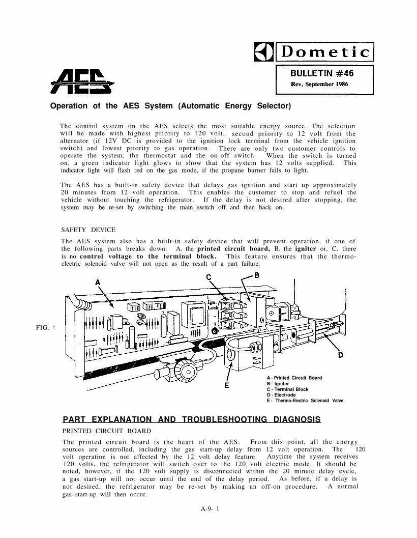
Operation of the AES System (Automatic Energy Selector)
The control system on the AES selects the most suitable energy source. The selectionwill be made with highest priority to 120 volt , second priority to 12 volt from thealternator (if 12V DC is provided to the ignition lock terminal from the vehicle ignitionswitch) and lowest priority to gas operation. There are only two customer controls tooperate the system; the thermostat and the on-off switch. When the switch is turnedon, a green indicator light glows to show that the system has 12 volts supplied. Thisindicator light will flash red on the gas mode, if the propane burner fails to light.
The AES has a built-in safety device that delays gas ignition and start up approximately20 minutes from 12 volt operation. This enables the customer to stop and refuel thevehicle without touching the refrigerator. If the delay is not desired after stopping, thesystem may be re-set by switching the main switch off and then back on.
SAFETY DEVICE
The AES system also has a built-in safety device that will prevent operation, if one ofthe following parts breaks down: A. the printed circuit board, B. the igniter or, C. thereis no control voltage to the terminal block. This feature ensures that the thermo-electric solenoid valve will not open as the result of a part failure.
FIG. 1
A - Printed Circuit BoardB - IgniterC - Terminal BlockD - ElectrodeE - Thermo-Electric Solenoid Valve
PART EXPLANATION AND TROUBLESHOOTING DIAGNOSISPRINTED CIRCUIT BOARD
The printed circuit board is the heart of the AES. From this point, all the energysources are controlled, including the gas start-up delay from 12 volt operation. The 120 volt operation is not affected by the 12 volt delay feature. Anytime the system receives120 volts, the refrigerator will switch over to the 120 volt electric mode. It should benoted, however, if the 120 volt supply is disconnected within the 20 minute delay cycle,a gas start-up will not occur until the end of the delay period. As before, if a delay isnot desired, the refrigerator may be re-set by making an off-on procedure. A normalgas start-up will then occur.
A-9- 1

Bulletin #46 continued
The circuit board on the AES also has the ability to monitor the 12 volt supply voltage.If the incoming voltage to the refrigerator drops below 9.5 (+- 1) volts, the AES willswitch to gas operation and the refrigerator will be unaffected by the thermostat. Untilthe low voltage situation is corrected, the system will remain on gas continually and willnot switch to 120 or 12 volt and overcooling or freezing will probably occur. As awarning device. the green indicator light will shut off during the voltage drop. Whenthe incoming voltage returns to 12 volts, the green indicator lamp will switch back onand the refrigerator will again return to the most suitable energy source. It must beremembered that the AES requires 12 volts at all times to operate on 120 volts, I2 voltor gas.
When a problem with the refrigerator system is being diagnosed and it is suspected thatthe circuit board is at fault, most likely the failure will be visible on the board itself.If the AES fails to operate and it is noted that there is a shorted wire between diodesor a shorted or burned section of the connecting foil on the circuit board, it is probablethat this circuit board is defective. Be sure the troubleshooting steps outlined below arefollowed BEFORE changing the board. The AES Analyzer (Part #800-0006-00/0) also maybe used to test the printed circuit boards.
HEATERS
MODEL OHM’S READING
3800 & 1303 AES 42 Ohm’s
3600 & 763 54 Ohm’s
3500 & 663 AES 82 Ohm’s
The 120 and 12 volt heaters that are included in the AES refrigerator contain a quickconnect contact plug - for ease of replacement. These plugs are polarized and will fitonly one way. When checking the electric element, you should notice a 42 ohm’s readingwith the 3800 and 1303 AES; 54 ohms on the 3600 and 763; and 82 ohms on the 3500 and663 AES. With these models on 12V operation, the heaters will draw 22.9, 20.8 and 15.8amps respectively.
SOLENOID VALVE
FIG. 3
12 VOLT SOLENOID VALVE
The AES uses a thermo-electric solenoid valve for openingand closing the gas supply line instead of the usualmanually operated safety valve. When the refrigerator isready to light on gas, the circuit board will send 12 voltsto the solenoid valve to open it. After the flame is litthe millivolts supplied from the thermocouple will keepthe solenoid valve open. The 12 volt signal current fromthe circuit board will drop off in IO-20 seconds after theflame is lit. To check the valve for operation, disconnectthe braided cable plug from the solenoid valve. Connect ajumper wire from the 12 volt posit ive terminal on therefrigerator to the lower lug on the solenoid valve. Whenthis is done, an audible click should be heard. This
indicates that the valve is operational. The solenoid valve should be replaced if it doesnot click open. If the valve opens, the D.C. voltage from the igniter must be checked.T O open the solenoid valve, there must be a positive pulse voltage between the yellowwire on the igniter (marked L) and ground. This pulse voltage is supplied by theigniter. It should be noted that the resistance cannot be checked across the terminals Whenthe solenoid valve without damaging the circuit board if the braided cable is connected.
A - 9 - 2

Bulletin #46 continued
The thermostat used in the AES system is a normalelectric thermostat without an off position. It operateson low voltage from the printed circuit board. I f thethermostat is broken and has lost its charge, therefrigerator will not operate on gas, 120 or on 12 volt.If i t is believed that the thermostat is broken, by-passthe thermostat by removing the two wires connected toit. Then place t h e t w o l e a d s f r o m t h e t h e r m o s t a ttogether and try for operation. The thermostat should bereplaced if the refrigerator now functions properly whenthe leads are connected.
Overfreezing will occur in the refrigerator if the thermostat capillary tube is not farenough into its holder. For the Model 1303 AES, the capillary tube distance should be35” to 36” from the tip of the sensing tube to the bottom of its holder; and on theModel 763 AES, it should be 31” to 32”. For the new s ty le the rmos ta t , Par tNo. / 9 AES, the capillary tube attaches to the evaporator on models 3800,3600, 3500 and 663 ONLY.
IGNITER
HIGHVOLTAGE
GAS IGNITER
The igniter operates with 12 volt current. On gasoperation the igniter senses the resistance throughthe flame between the electrode and burner. Whenthere is no flame at the burner, the resistance ishigh and the igniter begins sparking to l ight theburner. As soon as the flame is lit, the resistancebe tween the e lec t rode and burner d rops and theigniter stops sparking. The resistance is monitored bythe igniter and if for any reason the flame goes out,the igniter begins sparking unti l the burner is l i t .This insures that the flame will always be lit whendesired.
If the electrode does not spark, first make sure the igniter is receiving 12 volts. If theigniter is receiving 12 volts and produces no spark, it must be checked for operation.Remove the wire between the electrode and igniter and place 12 volts at the 12 volt +lug. If no internal clicking sound is heard, the igniter is broken. It is important toremove the high voltage wire that goes to the electrode from the igniter when you arechecking the igniter for operation. The high voltage wire and the electrode can beconnected to ground causing the circuit board to think that the flame is lit, resulting inno spark on gas operation. Moisture or dirt on the electrode itself will also affect theigniter. When diagnosing an igniter problem double check it to make sure the igniter isdry, clean and has proper gap (see FIG. 7).
INDICATION LAMPS
The indication lamp consists of two light emitting diodes; one green and one red. Whenthe 12 volt supply to the refrigerator is adequate to operate the system, the green lightshows. If the system runs out of propane fuel, the indicator light flashes red to warnyou that the gas supply is depleted. If the battery voltage drops below 9.5 (& 1) volts,the green indicator light will shut off to warn you of the low battery condition. At thistime, the flame will be continuously lit until the battery returns to 12 volts. It alsomust be remembered that all electrical connections in the AES are polarized, includingthe indicator lights. This l ight will show constant red and flashing green if i t isinserted upside down on the 1303. 763 and 663.
A-9-3

Bulletin #46 continued
MAIN SWITCH
ON/OFF SWITCHRM1303, 763, 663
Models 1303, 763 663:The switch operates on 12 volts from the circuit board. In normal operation, the switchshould travel only to the ON and OFF positions. A switch that travels more than thishas been installed incorrectly or the installation nut that holds the switch in place hasworked loose. If the switch is the suspected point of failure, check the connectingribbon cable for visible cuts or shorts . The switch can be checked for continuitybetween terminals 1 and 2, 4 and 5, 6 and 7 in the “ON” position; and 2 and 3, 5 and 7in the “OFF” position. Remember to disconnect the switch from the AES circuit boardwhen checking for continuity.
Models 3800, 3600 3500:Check for continuity only between terminals 1 and 2, 3 and 4, 5 and 10 using the lowscale (RX-l) on an ohm meter, with the switch in the ON position and continuity onlybetween terminals 1 and 3, 5 and 6 in the O F F posit ion. Also, be sure to disconnectfrom the AES circuit board and check continuity from the plug at the AES circuit boardend. This will check the ribbon cable as well as the switch.
ELECTRODE
FIG. 7
Spark Cap = 3/16" (Allen wrenchused for gas pressuretest fitting may beused as a feeler gauge)
The electrode serves two basic functions on the AES refrigerator. It is used as acontact point to transmit the spark from the igniter to the burner. The electrode alsoacts to measure the resistance between it and the burner and sends this information tothe igniter module. When the resistance is high, the igniter starts sparking and when itis low the igniter stops sparking. Because of this, the electrode position is extremelyimportant. If the electrode is too close to the burner the resistance is low and thesystem will think the burner is lit - especially true with high humidity. In thissituation, no spark will occur . Some atmospheric conditions such as very high humidityand/or coastal salt air may necessitate a wider than minimum gap; therefore, the optimumgap should be 3/16" or 5 mm. If the gap from the electrode to the burner is too large,the resistance will be too high and the igniter will continue to spark even though theflame is lit. With this situation, the flashing red indicator l ight will come on inapproximately 3 minutes.
A - 9 - 4

Bulletin #46 continued
In closing, there are two more external parts that can cause problems with your AESrefrigerator. First, if your propane supply to your refrigerator is depleted, no coolingon gas will take place and the red indicator light will flash. When it is noticed that theindicator light is flashing red, always check your fuel supply first. The second externalpart that may be causing the problem with the control system is the 12 volt battery. Ifa weak or dead battery is used to operate the refrigerator, the AES controls will notfunction properly. N O cooling or bad cooling on gas, electric and 12 volt will occur, ifthe battery is discharged or shorted. If the battery drops below 9.5 (+- 1) volts, therefrigerator will only be operational on gas. It has also been noted that the AES willoften overcool with a weak battery in line. No indicator or interior light and no controlfunctions indicate a weak or dead battery. Remember, without a constant 12 volt sourceto the refrigerator, the system will not work on 120 or 12 volt or on gas.
Some corrosion on the circuit boards resulting in malfunctions have been caused by wateror car wash solution being sprayed onto the back of the refrigerator through the sidevent door louvers. Sealing the circuit board enclosure should prevent recurrence;however, the owner should be made aware of this situation.
If you run into any problems that are not addressed here, please contact our TechnicalServices Department available to all Dealers, Service Centers and OEM's.
A - 9 - 5

AES REFRIGERATOR WIRING DIAGRAMS
6 6 3RM
CIRCUIT B o a r dR E L A YTerminal BlcokH E A T E RC O N N E C T O R SM A I N S W I T C HG A S F L A M E Warn. Lamp
RM763
@ T H E R M O S T A T@- G A S V A L V E C O I L
@ Thermocoup leI@- Reigni tor
WHITE B l a c k
@-- G R E E N
A - 1 0 - 1

AES REFRIGERATOR WIRING DIAGRAMS
RM1303
@ CIRCUIT B o a r d R E L A Y T E R M I N A L B l o c k
H E A T E R C O N N E C T O R S
@)- MAIN S W I T C H@ G A 5 F L A M E Warn. Lamp
H10 F
EIO G
+--i-QJ
u T
10 Sto U
R M 3500 - RM3600 - RM3800
C IR CU IT B O A R DR E L A YT E R M I N A L B L O C KH E A T E RC O N N E C T O R SM A I N S W I T C HG A S F L A M E W A R N L A M PFUNCTION L A M PD O O R S W I T C HL I G H TT H E R M O S T A TG A S V A L V E C O I LT H E R M O C O U P L EREIGNITORT I M E FU S E 3-3.15 A M PW H I T E - AWG I 3 A R E ABLACK - . 18 GREEN - ’ 24
A-10-2

CIRCUIT BOARD DIAGNOSIS
6/
1 . IF THIS LEAD IS DAMAGED: LOOK FOR A SHORT CIRCUIT OR DAMAGE INTHE INTERIOR L IGHT CABLE.
2 . IF THIS LEAD IS DAMAGED: LOOK FOR A SHORT CIRCUIT OR DAMAGE INTHE RIBBON CABLE TO THE MAIN SWITCHAND THERMOSTAT.
3 . IF TH IS COMPONENT IS DIS- CHECK ALL CABLES IN THE 12 VOLT SYSTEMCOLORED, BURNED OR BLOWN: FOR SHORT C IRCUITS .
4 . IF TH IS COMPONENT IS DIS- CHECK THAT THE 12 VOLT CONNECTIONS ARECOLORED, BURNED OR BLOWN: CORRECT AND THAT THERE IS A BATTERY
BETWEEN ALTERNATOR AND REFRIGERATOR.
5 . IF TH IS LEAD(S) I S D A M A G E D : CHECK FOR PROPER RESISTANCE IN OHM’SOF THE A/C HEATING ELEMENT AND ALL120 VOLT CABLES FOR SHORT CIRCUIT ORDAMAGE.
6 . IF TH IS COMPONENT IS D IS -COLORED, BURNED OR BLOWN:
CHECK FOR PROPER POLARITY OF GASSOLENOID LEAD.
7. I F TH IS COMPONENT IS D IS -COLORED, BURNED OR BLOWN:
CHECK FOR PROPER PLUG CONNECTIONS OFGAS SOLENOID AND THERMOSTAT ON CIRCUITBOARD. CHECK FOR SHORT CIRCUIT ORDAMAGE IN RIBBON CABLE TO INDICATORLIGHT, THERMOSTAT.
A-ll - l

o m e t i c lquality leisure line productr
AUTOMATIC ENERGY SELECTOR
Our technicians continue to get calls from the field regarding theflashing red light on the A.E.S. Refrigerators indicating a lackof understanding.
There can be times when the red light may flash, but there is nothingthat has malfunctioned in the refrigerator. In order to help ourcustomers make that determination, the following sequence is sug-gested.
1. Turn knob "A" (Main Switch) to position OFF. Wait 5 seconds andturn back to ON. The indicator light "E" should go to green andthe control system will begin a new sequence. If the-refrigeratorhas not been in operation for a while or the gas bottles have justbeen refilled, this operation may have to be repeated several timesto clear air from the gas line. (Each gas starting sequence willlast for about 3 minutes).
2. If the above question is not successful, check your gas supply,make sure that ALL gas valves between the refrigerator and the gasbottles have been opened. Don't overlook the gas shut off valve" a " in the back of the refrigerator.
3. Make sure the R.V. Battery is not discharged as the refrigeratorcan not function properly if the 12 Volt D.C. power is low.
4. If none of the above operations are successful, advise the custo-mer to bring the unit in for diagnosis.
B A
FIGURE A FIGURE B
RE: Page 7, DSC #304, Installation and Operating Instructions, AESRefrigerators
A-II-2

Replacement of Circuit
3-WAY AES CIRCUIT BOARDSRM3500,3600,3800
When working on an AES style refrigerator andreplacing the circuit board, the old board shouldbe visually inspected for any obvious damage,
3 i.e. burned components, damaged leads, burnedconnectors, corrosion, etc.
When the board is damaged, see the illustrationto the left for what to check and correct beforechanging the circuit board.
The following paragraph numbers relate to thecorresponding numbered items highlighted at thecircuit board.
-3 1. If this component is discolored, burnedor blown: Check that the 12V connectionsare correct and that there is a batterybetween alternator and refrigerator.
2. If this component is discolored, burnedor blown: Check all cables in the 12Vsystem for short circuits.
- 4If this component is discolored, burned
o r b lown: Check for proper polarity ofgas solenoid lead.
4. If this component is discolored, burnedor blown: Check for proper plug connec-tions of gas solenoid and thermostatc i rcu i t o r damage in r ibbon cable toindicator light, thermostat.
\5 5. If this lead is damaged: Check forproper resistance in Ohm’s of the A/Cheating element and in all 12OV cab le sfor short circuit or damage.
6. If these leads (dotted in the picture) atthe r ea r o f t h e b o a r d a r e damaged:Check for proper resistance in Ohm’s ofthe A/C hea t ing e lement and a l l 12OVcables for short circuit or damage.
A-ll-3

Bulletin #R56/7A continued
3-WAY AES CIRCUIT BOARDSRM3501,3601,3801,4801
Check the old circuit board before installing anew one. If damages as shown below are found,the defects causing the circuit board breakdownmust be corrected before the new one is installed.
The following paragraph numbers relate to thecorresponding numbered items highlighted at thecircuit board.
/I 1.
2.
3.
2 4.
1
5.
J3.2
If these areas are burned, the leadbetween the circuit board and thecontrol circuit board must be checkedfor short circuits.
If soldering at board rear is burned, theinterior light lead is likely to be shortedto ground.
If RI1 is blown the “Ignition Lock”voltage has been too high (over 12VDC f 10%).
If X5A, X5B, X5C, X5D a n d / o r K1 a r eburned (either side of the board), theAC voltage has been too high (over12OV AC + 1 0 % ) . Also check theheater in this case.
If V12 is burned, the solenoid leads canbe reversed.

Bulletin #R56/7A continued
2-WAY AES CIRCUIT BOARDSRM2602 AND RM2802
Check the old circuit board before installing anew one. If damages as shown below are found,the defects causing the circuit board breakdownmust be corrected before the new one is Installed.
The following paragraph numbers relate to thecorresponding numbered items highlighted at thecircuit board.
/’2 4.
- 1
- 1- 2
If this area is burned, the lead betweenthe c i r c u i t b o a r d a n d t h e c o n t r o lc i r c u i t b o a r d m u s t b e c h e c k e d f o rshort circuits.
If soldering at board rear is burned,the interior light lead is likely to beshorted to ground.
If X5A, X5B, X5C, and/or K1 are burned(e i the r s ide o f the board) , t h e A Cvoltage has been too high (over l2OVAC +- 10%). Also check the heater inthis case.
If V12 is burned, the solenoid leads canbe reversed.
A-ll-5

REPLACEMENT OF CIRCUIT BOARDSModels: RM663 RM763 RM1303
RefrigeratorBulletin R58/7A
April 1987 Rev. 5/87
When replacing the circuit board in the 663, 763 and 1303, you MUST, upon inspection of the b o a r d ,install the 12 Volt DC fuse provided. See Item #2, Page 2.
1. When working on an AES style refrigerator and replacing the circuit board, the old boardshould be visually inspected for any obvious damage, i.e. burnt components, damaged leads,burnt connectors, corrosion, etc.
a. When the board is damaged, see the following illustrations for what to check and correctbefore changing the circuit board:
FIG. 1
1.
2.
3.
4.
The following paragraph numbers relate to the same indicator numbers at the cidesi gnations.
rcuit board
If this lead is damaged: Look for a shortcircuit or damage in the interior light cable.
If this lead is damaged: Look for a shortcircuit or damage in the ribbon cable to themain switch and thermostat.
5. If this lead(s) is damaged: Check for properresistance in Ohm’s of the A/C heatingelement and all 120 volt cables for shortcircuit or damage.
6. If this component is discolored, burned or
If this component is discolored, burned orblown: Check all cables in the 12 volt system
blown: Check for proper polarity of gassolenoid lead.
for short circuits. 7. If this component is discolored, burned or
If this component is discolored, burned orblown: Check that the 12 volt connectionsare correct and that there is a battery betweenalternator and refrigerator.
blown: Check for proper plug connectionssolenoid and thermostat on circuitof gas
board. Check for short circuit or damage inribbon cable to indicator light, thermostat.
A-11-6

Bulletin #R58/7A continued
b. Verify that the positive (+) 12V. DC wire going to the circuit board is connected directlyto the coach battery positive (+) terminal.
VEHICLE ENGINE
FIG. 2
2. The electrical system should also be checked to assure the 12V. DC circuit has been fused; ifnot, see the following procedure:
Install the 12V. DC in-line fuse holder before the circuit board as shown in the illustration.One-quarter of an hour labor is authorized to install the fuse along with the standardtime approved to install the circuit board.
FIG. 3
j.
.I (1.A BS. UNIT
NOTE:(1) Install the 3.5 Amp fuse here for the 12V. DC line protection.
@ C IRCUIT BOARD@- RELAY
@ TERMINAL BLOCK HEATER CONNECTORS
@--- MAIN SWITCH GAS FLAME WARN. LAMP
THERMOSTAT($-- GAS VALVE COIL
@ THERMOCOUPLE@- REIGNITOR
@- WHITE BLACK
e GREEN
A-l1-7

Bulletin #R58/7A continued
Lastly, the moisture shield kit has been enclosed and can be installed to prevent corrosiondamage caused by water or car wash solution being sprayed into the back of the refrigeratorthrough the vent louvers. The circuit board compartment should be sealed in the followingmanner:
a. Install the shield under the bottom mounting bracket of the cooling unit. See the drawingbelow by model number. Seal the top edge with the foil tape supplied.
b. Seal around the conduit, where it goes into the circuit board compartment, with puttytape supplied or a silicon sealant can be used.
FOIL TAPEALONG TOP
Model 7 6 3 \ Model 663
NOTE: The earlv series only w h i c h h a s t h erectangular boiler enclosure, requiresthat the shield be bent across the middleslightly (I), with a little more angle onthe upper tab (2).
Models with the interior l ight conduit(3) coming out of the top of the circuitboard housing may require a tr immedslot and putty tape around the conduitand slot.
Caution should be used when washing the vehicleand avoid spraying water onto the refrigerator.
A-11-8

AES MODELS RM3601 3801MODULEBOARDREPLACEMENT
q D U O- TH E R M
RefrigeratorBulletin R59/7AMay 1987
NOTE: Please t a k e full consideration of the followinginformation BEFORE replacing module boards d u eto faulty 12 volt cooling operation.
This Bulletin clarifies the 12 volt DC start-up and coolingoperation.
Each time the tag line is energized and 12 volt cooling isselected, the module board must receive approximately 13.6volts for about 40 or more seconds. At tha t t ime theunit will engage the 12volt heating element. Ifthe initial required 13.6volts is not achieved (dueto demands of other 12volt devices) the AES willnot switch to 12 voltoperation, and will operateinstead on L.P. gas until the13.6 volt threshold is reached.
If during 12 volt cooling, supply voltage should drop belowapproximately 11.6 volts (FIG. 2), the DC cooling will shutdown and the AES system will go into a 25 minute delay (FIG.3). This allows the supply voltage to re-establish itself.
To view the delay, push the button identified with a questionmark q and the clock indicator light a will come on.
NOTE: If 13.6 volts is not recovered during the delay the AESsystem will then switch to gas operation until the supply voltagerecovers. If during the 25 minute delay the 13.6 thresholdvoltage is recovered, the delay will be deleted and 12 volts DCcooling will resume.
FIG. 1
FIG. 2
AES CONTROL PANEL ON REFRIGERATOR
FIG. 3
As with all AES refrigerators, minimum voltage for a n yoperation is 10.5 volts DC at the terminal block.
FIG. 4
IGNLOCK
- - -
- - -+
1
A-l1-9

PDI(PRE- D E L I VE R Y INSPECTION)
PDI insures safe operation of Dometic Refrigerators. The follow-ing checks on each unit are advised before being operated bythe consumer. If each refrigerator is inspected according tothese guidelines, you can be assured of peak performance fromyour Dometic refrigerator.
3 - W a yRM1303
ON ..........
.......................
3-Way
RM3501RM3601RM3801
GREENOFF/ONSWITCH
. . . .
RM3500RM3600RM3800
O F F ON. . . . . . . . . . .
. . . . . . . . . . . . . ...* . . . . . .. . . . . . . . ...*
2-Way
RM2602RM2802
A - I I - 1 0

Bulletin #R60/7A continued
This refrigerator is equipped with an AutomaticEnergy Selector System. The selection will bemade with the highest priority to 120 volts;second priority to 12 volts from the battery ifthe ignition is turned on; and with the lowestpriority to gas operation.
AESPRE-DELIVERY CHECK FOR
MODEL RM1303 AES REFRIGERATOR
OPERATIONAL TESTS
A.
B.
C.
D.
E.
F.
G.
Have 120 volt supply available
Make sure you have a good 12 volt batterysupply.
Make sure gas valves at tank and rear ofrefrigerator have been turned on.
Turn ON/OFF switch to ON (bottom rightfront of refrigerator.
Set thermostat to setting above #4 (secondknob from right).
Connect 120 volt supply. Green indicatorlight should be on.
Check boiler box to see if it is warming up.
CAUTION: This area becomes extremelyhot and can cause burns.
I. Supply 12 volts to ignition lock terminal atrear of refrigerator, or start engine. Flameshould go out
Remove 12 volt from ignition position. Theunit should now be in a gas delay. Thisdelay should be approximately 20 minutes.
OVER-RIDE DELAY1. Turn ON/OFF switch from ON to OFF,
wait approximately 5 seconds and turnback ON.
2. The burner should re-light in approximately15 seconds.
NOTE: FLASHING RED LIGHT: This indicates
J.
K
L. I f the above tes t s a re per formed wi thoutfault, the AES is operating properly.
the unit tried to light on gas andfailed. It is possible the unit had airin the lines. Reset the controls.
Make sure the AES is wired directly tobattery with 30 amp breaker within 18inches of battery.
H. Disconnect the 120 volt supply at rear ofrefrigerator compartment. T h e A E S u n i tshould go to gas operation. Check burnerbox to see if flame is lit.
A-11-11

Bulletin #R60/7A continued
AES
NOTE: The above model numbers are upgradedversions of the AES system.
Normal operation will be the same asfirst generation. The units will havethe following changes: Switch, Thermostatand Light.
1. The ON/OFF switch is located at the top rightside of the refrigerator.
2. The first light to the right of the ON/OFF
PRE-DELIVERY CHECK FORMODEL RM3500, RM3600, RM3800
switch is the green light. When the ON/OFFswitch is in the ON position, this light willbe green.
3. The second light to the right of the ON/OFFswitch is the FLAME FAILURE light. Thiswill flash if the unit fails to light on gas.
4.
5.
The refrigerator is equipped with a thermostatwhich is located inside the cabinet on thefront of the light fixture.
/LIGHT BULB
DOOR SWITCH FORINTERIOR LIGHT
THERMOSTATKNOB
This i s regu la ted by tu rn ing the knob todifferent settings in order to obtain desiredcabinet temperatures. The closer the knobis set to maximum, the lower the temperature.
GREENOFF/ONSWITCH
;F&;ATIONALKpLlKt
A - l 1 - 1 2

Bulletin #R60/7A continued
AES
PRE-DELIVERY CHECK FORMODELS RM3601 AND RM3801
1. The AES automatically selects the best energy source for the situation, either 120 volts, 12volts or LP gas.
2. This unit will also let you select the energy source you want.
3. Pictured below is the AES control panel that is found on this generation of AES refrigerators.
A B C D E F G H J K
A. Push button, green indicator - Full AES operation.
B. Push button, green indicator - Limited AES operation:
C.
D.
E.
F.
G.
H.
I.
J.
AES CONTROL PANEL ON REFRIGERATOR
120 volts or LP gas (priority to 120 volts).
Push bottom, green indicator - LP gas operation only.
Main switch - Push right, to turn unit ON. Push left to turn unit OFF.
Yellow indicator - 120 volt operation mode.
Yellow indicator - 12 volt operation mode.
Yellow indicator - LP gas delay mode.
Yellow indicator - LP gas operation.
Question mark - push button. When pushed this button will indicate which mode is inoperation, E-F-G or H.
Flame Failure indicator - Indicates unit tried to light on LP gas and failed.
OPERATIONAL TEST6.
Make sure you have a good 120 volt supplyavailable. 7.
You must also have a good 12 volt supply.
Be sure all LP gas valves have been turnedon, those at LP tanks and at rear of refriger-ator.
Turn ON/OFF switch “D” to the ON position. 8.
D
Connect 120 volt supply to unit.
When switch “D” is set to ON, the AESbutton will light up (green), indicating thatthe control system is in the automatic mode.In this mode 120 volts A/C has priority.
Push the question mark button “J”. Nowyellow indicator “E” (A/C) should light up.
OFF ONJ E
A-ll-13

Bulletin #R60/7A continued
9.
IO.
1 1.
12.
When switch "B" is pushed, the control systemwill select only between 120 volts A/C andLP gas operation. To check, push questionmark button “J”. Indicator light “E” shouldlight up.
B E- -[AC/n 1 ; cl? = AC
- -
To check gas operation of switch “B”, remove120 volt supply from rear of refrigerator.Push switch “J” (question mark). Flameindicator should light.
When switch “C” is pushed the refrigeratorwill operate only on LP gas, even if 120 voltA/C or 12 volt DC is available.
To check gas operation of switch “C”: Pushquestion mark “J”. Flame indicator light “H”should now light.
C H
Ih i5 El?=n- -
Indicator “K ” flame failure. This indicatorwill light only when there has been a flamefailure in the LP gas operation mode. Torestart gas operation, set switch “D” to OFF.
13.
Wait 5 seconds, then switch back to ON.Flame failure indicator will go off, and systemwill start another cycle for ignition.
K
Indicator “G”. This light will come on whenengine is turned off. The AES system goesinto a delay cycle which prevents LP gasoperation for 25 minutes. This is a refuelingprecaution. If the engine is started duringthe delay cycle, 12 volts will resume and thedelay period will be reset to 25 minutes.This means every time the engine is turnedoff, you will have a complete 25 minute delay.
G
NOTE: Each time tag line is energized and12 volt cooling is selected, themodule board must receive approxi-mately 13.6 volts for 40 or moreseconds. At that time the unit willengage the 12 volt heating element.If initial 13.6 volts is not achieved(due to demands of other 12 voltdevices in the vehicle), the AES willnot switch to 12 volt operation andwill operate instead on gas until the13.6 volt threshold is achieved.
As with all AES refrigerators, minimumvoltage for any operation is 10.5volts DC at the terminal block.
A-l1-14

Bulletin #R60/7A continued
FREEDOM SERIES
RM 2802
(PDI) PRE-DELIVERY INSPECTION
PDI insures safe operation of Dometic refrigerators. The followingchecks on each unit are advised before being operated by the consumer.If each refrigerator is inspected according to these guidelines, youcan be assured of peak performance from your Dometic refrigerator.
1.
2.
3.
4.
ORANGE continuous light: Indicates gas ignition failure - no gas.
MAIN SWITCH
PUSH BUTTON: Green - indicates gas operation ONLY.
PUSH BUTTON: Green - Gives energy selection between A/C and Gas.
NOTE: No 12 volt power selection possible.
OPERATIONAL TEST 3. Disconnect 120 volt cord. The refrigerator
A.
B.
C.
D.
E.
Have 120 volt A/C supply available.
Be sure you have a good 12 volt battery supply.
Make sure gas valves, both at tank and rearof refrigerator, have been turned on.
should now light on gas. If this is notaccomplished in approximately 3 minutes,the Flame Failure Light will come on.
1
Turn ON/OFF switch to “ON” position.
To correct this turn main switch OFFand the back to ON. The green A/C flamelight should come on again.
Set
1.
2.
thermostat to “NORMAL” position.
Plug coach 120 volt cord into 120 voltoutlet.
Green A/C flame light #4 should be on.
4AC
4. To check GAS ONLY operation, push #3,Green Flame Light. The system willthen operate on gas regardless if 120 voltpower is present. If unit fails to light, Flame Failure Light will come on. TurnOFF main switch and then turn back toON. Unit should now be lit on GAS.
3
A-l l-15

GENERAL INFORMATIONFOR MODELS RM2602 & RM2802
The refrigerator is equipped with an Once the low voltage has been cor-energy selector system. The system rected, the control system goes backselects the mos t suitable available to normal operation. To indicateenergy source. The selection will be that the control system is in a lowmade with the highest priority tovolts and the lowest priority tooperation.
If the gas mode is chosen, thewill operate on gas only, even ifvolts are present.
120gas
unit120
DC voltage condition the selectormode[ A/C GAS ] indicator will be turnedoff. The interior light is unaffectedduring the entire procedure.
The control system always requires12 volts DC to be able to operateon ANY energy mode. Below 9.5volts DC the control system will goto gas with no thermostat control.
If the refrigerator does not succeedin lighting on gas the first time,turn unit OFF and then ON sincethere might be air in the lines.
A-12

AES REFRIGERATOR DIAGNOSTICSERVICE MANUAL
OS1160-A
A - lA-2A-3A-4A-5-lA-5-2A-5-3
A-5-4A-5-5
A-6-lA-6-2A-6-3A-6-4A-6-5A-6-6A-6-7A-6-8A-6-9A-6- 10A-6-11A-6- 12A-6-13A-6-14A-6-15A-6-16A-6-17A-6-18A-6-19A-6-20A-6-21A-6-22A-6-23A-6-24A-6-25A-6-26A-6-27A-6-28A-6-29A-6-30A-6-31A-6-32A-6-33A-6-34A-6-35A-6-36A-6-37A-6-38A-6-39A-6-40A-6-41A-6-42A-6-43A-6-44A-6-45A-6-46
Description
Title PageNotesTable of ContentsNotesAES Refrigerator Diagnostic Flow Chart / No OperationAES Refrigerator Diagnostic Flow Chart / No 120V AC OperationAES Refrigerator Diagnostic Flow Chart / No 12V DC Operation
(Checks AES Mode Only)AES Refrigerator Diagnostic Flow Chart / No Gas OperationAES Refrigerator Diagnostic Flow Chart / No Gas Operation
(continued)Operation and Diagnosis - Dometic AES RefrigeratorOperation and Diagnosis - Dometic AES Refrigerator (continued)Operation and Diagnosis - Dometic AES Refrigerator (continued)Operation and Diagnosis - Dometic AES Refrigerator (continued)Operation and Diagnosis - Dometic AES Refrigerator (continued)Operation and Diagnosis - Dometic AES Refrigerator (continued)Operation and Diagnosis - Dometic AES Refrigerator (continued)Operation and Diagnosis - Dometic AES Refrigerator (continued)Operation and Diagnosis - Dometic AES Refrigerator (continued)Operation and Diagnosis - Dometic AES Refrigerator (continued)Operation and Diagnosis - Dometic AES Refrigerator (continued)Operation and Diagnosis - Dometic AES Refrigerator (continued)Operation and Diagnosis - Dometic AES Refrigerator (continued)Operation and Diagnosis - Dometic AES Refrigerator (continued)Operation and Diagnosis - Dometic AES Refrigerator (continued)Operation and Diagnosis - Dometic AES Refrigerator (continued)Operation and Diagnosis - Dometic AES Refrigerator (continued)Operation and Diagnosis - Dometic AES Refrigerator (continued)Operation and Diagnosis - Dometic AES Refrigerator (continued)Operation and Diagnosis - Dometic AES Refrigerator (continued)Operation and Diagnosis - Dometic AES Refrigerator (continued)Operation and Diagnosis - Dometic AES Refrigerator (continued)Operation and Diagnosis - Dometic AES Refrigerator (continued)Operation and Diagnosis - Dometic AES Refrigerator (continued)Operation and Diagnosis - Dometic AES Refrigerator (continued)Operation and Diagnosis - Dometic AES Refrigerator (continued)Operation and Diagnosis - Dometic AES Refrigerator (continued)Operation and Diagnosis - Dometic AES Refrigerator (continued)Operation and Diagnosis - Dometic AES Refrigerator (continued)Operation and Diagnosis - Dometic AES Refrigerator (continued)Operation and Diagnosis - Dometic AES Refrigerator (continued)Operation and Diagnosis - Dometic AES Refrigerator (continued)Operation and Diagnosis - Dometic AES Refrigerator (continued)Operation and Diagnosis - Dometic AES Refrigerator (continued)Operation and Diagnosis - Dometic AES Refrigerator (continued)Operation and Diagnosis - Dometic AES Refrigerator (continued)Operation and Diagnosis - Dometic AES Refrigerator (continued)Operation and Diagnosis - Dometic AES Refrigerator (continued)Operation and Diagnosis - Dometic AES Refrigerator (continued)Operation and Diagnosis - Dometic AES Refrigerator (continued)Operation and Diagnosis - Dometic AES Refrigerator (continued)Operation and Diagnosis - Dometic AES Refrigerator (continued)Operation and Diagnosis - Dometic AES Refrigerator (continued)Operation and Diagnosis - Dometic AES Refrigerator (continued)Operation and Diagnosis - Dometic AES Refrigerator (continued)Operation and Diagnosis - Dometic AES Refrigerator (continued)

OS1160-A AES Refrigerator Diagnostic Service Manual (continued)
A-6-47A-6-48A-6-49A-7- lA-7-2A-7-3A-7-4A-7-5A-7-6A-7-7A-8- l
A-8-2
A-8-3
A-8-4
A-8-5
A-9- 1A-9-2A-9-3A-9-4A-9-5A-10-1A- 10-2
A-11-1A-ll-2A-ll-3A-ll-4A-ll-5A-ll-6
A-11-7A-11-8A-ll-9
A-11-10A-11-11A-11-12A-l1-13A-ll-14A-ll-15A-12A-13A-14A-15
Description
Operation and Diagnosis - Dometic AES Refrigerator (continued)Operation and Diagnosis - Dometic AES Refrigerator (continued)Operation and Diagnosis - Dometic AES Refrigerator (continued)AES Refrigerator Glossary of TermsAES Refrigerator Glossary of Terms (continued)AES Refrigerator Glossary of Terms (continued)AES Refrigerator Glossary of Terms (continued)AES Refrigerator Glossary of Terms (continued)AES Refrigerator Glossary of Terms (continued)AES Refrigerator Glossary of Terms (continued)3801 AES Refrigerator Continuity Readings for Switch Card &
Harness3801 AES Refrigerator Continuity Readings for Switch Card &
Harness (continued)3801 AES Refrigerator Continuity Readings for Switch Card &
Harness (continued)2802 AES Refrigerator Continuity Readings for Switch Card &
Harness2802 AES Refrigerator Continuity Readings for Switch Card &
Harness (continued)Bulletin #46 Operation of AES SystemBulletin #46 (continued)Bulletin #46 (continued)Bulletin #46 (continued)Bulletin #46 (continued)AES Refrigerator Wiring Diagram RM663 & RM763AES Refrigerator Wiring Diagram RM1303 & RM3500, 3600 &
RM3800Bulletin #51 Circuit Board DiagnosisBulletin #53 Automatic Energy SelectorBulletin R56/7A Replacement of Circuit BoardBulletin R56/7A (continued)Bulletin R56/7A (continued)Bulletin R58/7A Replacement of Circuit Board RM663, RM763,
RM1303Bulletin R58/7A (continued)Bulletin R58/7A (continued)Bulletin R59/7A AES Models 3601-3801 Module Board
ReplacementBulletin R60/7A AES PDIBulletin R60/7A (continued)Bulletin R60/7A (continued)Bulletin R60/7A (continued)Bulletin R60/7A (continued)Bulletin R60/7A (continued)General Information for Models RM2602 & RM2802NotesAES Refrigerator Diagnostic Service Subscription Order FormBlank

����������� ������ �������������� ��� ���������������
�������������� �� �� ����� �� � �� ����������������������������� �������������
� ��� ������������� ��������� ���� ���������������� ������������� ��� �� ��� �� �������� ����� ���������� ��������� ������������������������ ����� ��� �������������������������� ������� ������ ��� ��� ����������� !"��� � ������������������ ��� � !����������������#$%�&����� '����� ���
(����������������������� �������&� �� ����� ����������'�
��������������