Embed Size (px)
Citation preview
1/1
Ilaria Mod. 703T-I
Ilaria Mod. 703T-IL
Ilaria Mod. 703T-G
Ilaria Mod. 703T-GL
Domestic Solid Fuel Cooker With Boiler
INSTALLATION, USER AND MAINTENANCE
MANUAL
Equipments built in conformity with European Norms for marking
mod. 703T-I / 703T-IL / 703T-G / 703T-GL GBGBGBGB
2/2
Cod. 90003051 Rev. 0
Dear Customer,
Thank you for purchasing our product. Please take some time to read this manual
and understand the contents. There are important warnings which you must read
about installation, use, maintenance and product safety. Failure to adhere to the
warnings may invalidate your warranty, insurance and breach the law.
INDEX
Chap. Description Pag.
1 Installation 3
1.1 Legal requirements 3 1.2 Preliminary operations 3 1.3 Appliance positioning 3 1.4 Connection 4 1.5 Technical details 10
2 Using 11
2.1 Important warnings 11 2.2 Combustible 11 2.3 Starting 12
3 Maintenance and cleaning 19
3.1 Ordinary maintenance 19 3.2 Extraordinary maintenance 21 3.3 Accessories 21 3.4 Possible failure and its solution 22
4 Technical data plate 25
mod. 703T-I / 703T-IL / 703T-G / 703T-GL GBGBGBGB
3/3
1 INSTALLATION
RESERVED FOR INSTALLERS
1.1 Legal requirements
• Carefully read the contents of this handbook, it contains important information and instructions for installation, use, maintenance and product safety.
• The appliance must be installed in an environment considered suitable for installation and use by competent person or persons. All laws, standards and regulations in force on the installation site must be observed, especially regarding fire prevention.
• Appliance installation and all associated work must in carried out and inspected in accordance with the relevant regulations and standards.
• All relevant Health and Safety precautions should be taken. • As required correct Local Authority Planning Permission and Listed Building consent
should be obtained before starting work. • All laws, standards and regulations in force on the installation site must be observed in
relation to the installation. • The installation must be carried out in accordance to UK Building Regulations and
certified to this standard before use. • The manufacturer disclaims all damage responsibility caused by not correctly
installing, using, maintaining or taking appropriate safety precautions with the appliance.
1.2 Preliminary operations • Remove the packing. • Inspect the appliance for shipping damage. Report any damage immediately to your
dealer. • The appliance is heavy, you will need to make suitable provisions to move it. • Packing materials is for recycle, putting it in specific container. 1.3 Appliance positioning • The installation location should have:
− A suitable floor for appliance’s weight. − The floor or hearth should comply with UK Building Regulations. − A suitable chimney or flue system. − The appliance should be at least as far as UK Building Regulations state from any
flammable materials. − A suitable external fresh air supply.
HEARTH CONSTRUCTION The appliance does not need a constructional hearth.
mod. 703T-I / 703T-IL / 703T-G / 703T-GL GBGBGBGB
4/4
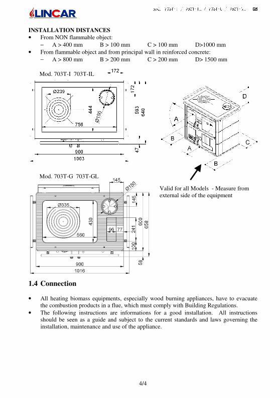
Valid for all Models - Measure from external side of the equipment
Mod. 703T-G 703T-GL
Mod. 703T-I 703T-IL
INSTALLATION DISTANCES
• From NON flammable object:
− A > 400 mm B > 100 mm C > 100 mm D>1000 mm
• From flammable object and from principal wall in reinforced concrete:
− A > 800 mm B > 200 mm C > 200 mm D> 1500 mm
1.4 Connection
• All heating biomass equipments, especially wood burning appliances, have to evacuate the combustion products in a flue, which must comply with Building Regulations.
• The following instructions are informations for a good installation. All instructions should be seen as a guide and subject to the current standards and laws governing the installation, maintenance and use of the appliance.

mod. 703T-I / 703T-IL / 703T-G / 703T-GL GBGBGBGB
5/5
COLLAR EXHAUST FUMES ASSEMBLY
• Place the collar over the plate (Fig.1) and fix it to the plate using the enclosed screws.
CLEANING TOP PLATE
The top plate has been treated with a lubricating oil to avoid rusting, so it’s necessary to clean it before igniting the appliance. CHIMNEY OR FLUE
• The chimney or flue should have the following characteristics:
− The flow has to be vertical with deflections no more than 45°.
− A minimum distances from combustible or flammable material, must be adheired to.
− The chimney should always be swept before installation and at least once a year there after.
− All manufacturer instruction should be respected concerning the section and the building characteristic of the chimney or flue. For particular section, deviation of section or path it will be necessary a complete inspection of exhaust fumes system.
When installing the appliance care must be taken to ensure it is easy to clean and maintain. The chimney must be cleaned at least once a year and the top of the appliance removed for cleaning. This must be able to be done without moving the appliance. −
CHIMNEY OR FLUE
• The flue or chimney must comply with the relevant Building Regulations and be certified that it complies with the regulations before it is used.
• The flue should not be shared with any other appliance or fireplace. It must only be for this appliance.
•
• It’s prohibited to connect the flue to any other appliance including a suction hood.
• The flue pipe must vent to the outside. FRESH AIR FEED
• The equipment should have the necessary air for combustion, supplied by a permanently open external air vent. The appliance is rated at 27.3Kw, the air supply must be sufficient for a minimum of this amount.
• The external air supply inflow can be supplied from an adjacent room, but the air intake from the adjacent room must be permanently open as well as the external air supply to the adjacent room.. No additional chimney or suction hood should be present in the installation room or in the connected adjacent room.
NOTE: The air inflow hole must be placed at a low level in the wall.
NOTE: Extractor fans when operating in the same room or space as the appliance may cause
problems.
Exhaust fumes collar
Radiant plate
Plate frame
mod. 703T-I / 703T-IL / 703T-G / 703T-GL GBGBGBGB
6/6
NOTE: The installation room should not be in lower pressure due to other appliances such as
suction hoods, chimneys, and evacuation flues, present in the room itself or in the adjacent
rooms, which are in communication.
CONNECTION TO THE HEATING SYSTEM
• The manufacturer disclaims all responsibility caused by incorrect installation, use, tampering, maintenance or misuse of the product.
• The installation of the appliance and the connection to the heating system must be
carried out by a qualified person and certified in accordance with Building
Regulations before use
• Stopcocks must be installed on the connections to the appliance, so the appliance can be isolated if it needs to be disconnected for maintenance and/or repair purposes.
• Water or steam exhaust tubes and safety pipes must release in an adequate place in order to avoid damages to the appliance or to the installation place.
• Flexible tubes are preferred to connect the appliance to the heating system.
• In order to avoid problems arising from residuals and/or deposit, it is highly recommended that the system is fully flushed before connecting the appliance.
• The installation of the appliance must have an open expansion tank: A pressure release Valve (3bar) must be applied to the system as well as a thermometer of the boiler water temperature. All safety devices must be accessible after the installation, in order to allow an easy maintenance and the control of their function.
• We recommend setting the start control of the circulator (pump) so that the water begins to circulate at a temperature of 55° - 60°C, lower temperature could create condensate on the wall of the boiler.
• A drain tap should be installed on the return to the boiler, to enable the system to be drained.
• Before using the appliance it is necessary to fill the boiler of the cooker, as well as the heating system and eliminate any possible air bubbles.
• A corrosion inhibitor must be used in the heating system.
• It is strictly forbidden to use the appliance if it is not connected to a functioning heating system.
• Stopcock taps, if installed, must always be opened while operative.
mod. 703T-I / 703T-IL / 703T-G / 703T-GL GBGBGBGB
7/7
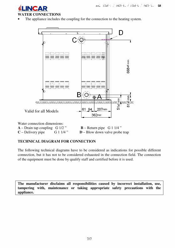
WATER CONNECTIONS
• The appliance includes the coupling for the connection to the heating system.
Water connection dimensions: A – Drain tap coupling G 1/2 ” B – Return pipe G 1 1/4 ” C – Delivery pipe G 1 1/4 ” D – Blow down valve probe trap
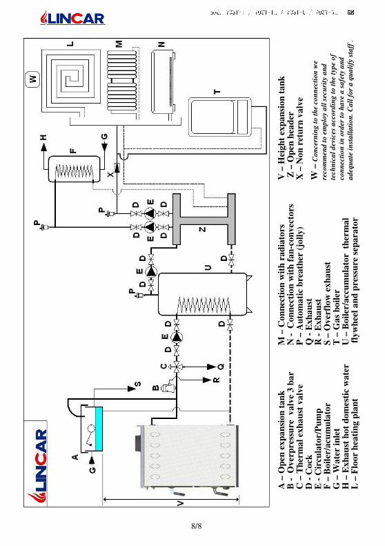
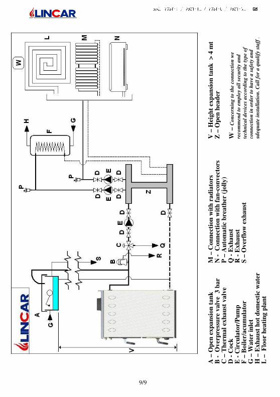
TECHNICAL DIAGRAM FOR CONNECTION
The following technical diagrams have to be considered as indications for possible different
connection, but it has not to be considered exhausted in the connection field. The connection
of the equipment must be done by qualify staff and certified before it is used.
The manufacturer disclaims all responsibilities caused by incorrect installation, use,
tampering with, maintenance or taking appropriate safety precautions with the
appliance.
Valid for all Models
mod. 703T-I / 703T-IL / 703T-G / 703T-GL GBGBGBGB
8/8
A –
Op
en e
xp
an
sio
n t
an
k
B
-
Ov
erp
ress
ure
v
alv
e 3
ba
r C
– T
her
ma
l ex
ha
ust
va
lve
D
- C
ock
E
- C
ircu
lato
r/P
um
p
F –
Bo
iler
/acu
mu
lato
r G
– W
ate
r in
let
H
– E
xh
au
st h
ot
do
mes
tic
wa
ter
L
– F
loo
r h
eati
ng
pla
nt
M –
Co
nn
ecti
on
wit
h r
ad
iato
rs
N -
C
on
nec
tio
n w
ith
fa
n-c
on
vec
tors
P
– A
uto
ma
tic
bre
ath
er (
joll
y)
Q -
Ex
ha
ust
R
- E
xh
au
st
S –
Ov
erfl
ow
ex
ha
ust
T
– G
as
bo
iler
U
– B
oil
er/a
ccu
mu
lato
r t
her
ma
l f
lyw
hee
l a
nd
pre
ssu
re s
epa
rato
r
V –
Hei
gh
t ex
pa
nsi
on
ta
nk
Z
– O
pen
hea
der
X
– N
on
ret
urn
va
lve
W
– C
on
cern
ing
to
th
e co
nn
ecti
on
we
reco
mm
end
to
em
plo
y a
ll s
ecu
rity
an
d
tech
nic
al
dev
ices
acc
ord
ing
to
th
e ty
pe
of
con
nec
tio
n i
n o
rder
to
ha
ve a
sa
fety
an
d
ad
equ
ate
in
sta
lla
tio
n.
Ca
ll f
or
a q
ua
lify
sta
ff .
mod. 703T-I / 703T-IL / 703T-G / 703T-GL GBGBGBGB
9/9
A –
Op
en e
xp
an
sio
n t
an
k
B
-
Ov
erp
ress
ure
va
lve
3 b
ar
C –
Th
erm
al
exh
au
st v
alv
e
D -
Co
ck
E -
Cir
cula
tor/
Pu
mp
F
– B
oil
er/a
cum
ula
tor
G –
Wa
ter
inle
t
H –
Ex
ha
ust
ho
t d
om
esti
c w
ate
r
L –
F
loo
r h
eati
ng
pla
nt
M –
Co
nn
ecti
on
wit
h r
ad
iato
rs
N -
C
on
nec
tio
n w
ith
fa
n-c
on
vec
tors
P
– A
uto
ma
tic
bre
ath
er (
joll
y)
Q -
Ex
ha
ust
R
- E
xh
au
st
S –
Ov
erfl
ow
ex
ha
ust
V –
Hei
gh
t ex
pa
nsi
on
ta
nk
>
4 m
t Z
– O
pen
hea
der
W
– C
on
cern
ing
to
th
e co
nn
ecti
on
we
reco
mm
end
to
em
plo
y a
ll s
ecu
rity
an
d
tech
nic
al
dev
ices
acc
ord
ing
to
th
e ty
pe
of
con
nec
tio
n i
n o
rder
to
ha
ve a
sa
fety
an
d
ad
equ
ate
in
sta
lla
tio
n.
Ca
ll f
or
a q
ua
lify
sta
ff .
mod. 703T-I / 703T-IL / 703T-G / 703T-GL GBGBGBGB
10/10
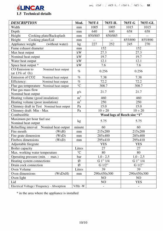
1.5 Technical details
DESCRIPTION Mod. 703T-I 703T-IL 703T-G 703T-GL
Width mm 1005 1005 1015 1015
Depth mm 640 640 658 658
Height Cooking plate/Backsplash mm 850/885 850/885 -- --
Height Cooking plate/Lid mm -- -- 855/890 855/890
Appliance weight (without water) kg 227 252 245 270
Fume exhaust diameter mm 152 152
Max heat output kW 27.3 27.3
Nominal heat output kW 19.7 19.7
Water heat output kW 12.1 12.1
Space heat output * kW 7.6 7.6 CO Emission to Nominal heat output (at 13% of O2)
% 0.256 0.256
Emission of CO2 Nominal heat output % 7.38 7.38
Efficiency: Nominal heat output % 72.2 72.2
Flue gas temperature Nominal heat output °C 308.7 308.7 Flue gas mass flow Nominal heat output
g/s 21.7 21.7
Heating volume (good insulation) m3 460 460
Heating volume (poor insulation) m3 250 250
Chimney draft in Test Nominal heat output Pa 15.0 15.0
Chimney draft: Min - Max Pa 10 ÷ 20 10 ÷ 20
Combustible Wood logs of Beech size “1” Maximum per hour fuel use Nominal heat output
kg 5.75 5.75
Refuelling interval Nominal heat output minute 60 60
Fire mouth (WxH) mm 215x200 215x200
Fire grate dimension (WxD) mm 285x400 285x400
Firebox dimensions (WxD) mm 295x410 295x410
Adjustable firegrate YES YES
Boiler capacity Litres 27 27
Max. working water temperature °C 80 80
Operating pressure (min. - max.) bar 1,0 - 2,5 1,0 - 2,5
Heating system connections Ø G 1” 1/4 G 1” 1/4
Drain cock connection Ø G 1/2” G 1/2”
Oven Volume Litres 39 39
Oven dimensions (WxDxH) mm 290x450x300 290x450x300
Oven light NO NO
Lid NO YES Electrical Voltage / Frequency - Absorption V/Hz -W - -
* in the area where the appliance is installed
mod. 703T-I / 703T-IL / 703T-G / 703T-GL GBGBGBGB
11/11
2 USING THE APPLIANCE
2.1 Important warnings • Read carefully the instructions in this section, which are very important for the use,
maintenance and safety of the appliance.
• This handbook has to be read and studied in full. Failure to read can be considered as
improper use of the equipment and therefore not correct use of the appliance.
• Take care of this handbook and use it every time it is necessary.
• The appliance should be employed only for the use for which it has been intended; any
other use could be dangerous.
• The appliance should not be utilized as an incinerator.
• The working of the appliance creates high temperatures on some internal and external
surfaces, with which user could touch: be careful and pay attention!
• The whole appliance should be consider as an active area of heat production, with many
hot surfaces, therefore children, animals and disabled people should not come in direct
contact with the appliance.
• Use the glove provided when opening the doors.
• The correct use of the stove is with closed doors, if the fire door glass is broken and / or
damaged or in case of bad functioning, the stove must not be lit until the problem has
been solved.
• The operation of the appliance must always be supervised.
• Any maintenance operation, repairs or substitution, should be effected by a qualified
after-sales service. Pretend original spare parts, only.
• Do not tamper with the appliance. Do not obstruct air vents or heat dissipation openings. • Every local, National or European law in force has to be respected during the installation. • The safety distances from flammable material has to be observed and all the prescriptions
contained in chapter 1
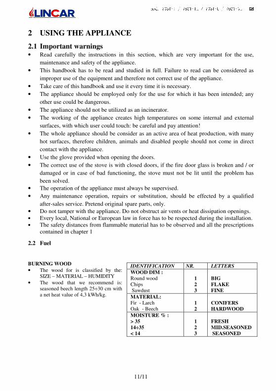
2.2 Fuel
BURNING WOOD
• The wood for is classified by the: SIZE – MATERIAL – HUMIDITY
• The wood that we recommend is: seasoned beech length 25÷30 cm with a net heat value of 4,3 kWh/kg.
IDENTIFICATION NR. LETTERS
WOOD DIM :
Round wood Chips Sawdust
1
2
3
BIG
FLAKE
FINE
MATERIAL:
Fir - Larch Oak - Beech
1
2
CONIFERS
HARDWOOD
MOISTURE % :
> 35
14÷35
< 14
1
2
3
FRESH
MID.SEASONED
SEASONED
mod. 703T-I / 703T-IL / 703T-G / 703T-GL GBGBGBGB
12/12
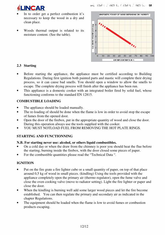
• In to order get a perfect combustion it’s necessary to keep the wood in a dry and clean place.
• Woods thermal output is related to its moisture content. (See the table).
2.3 Starting
• Before starting the appliance, the appliance must be certified according to Building Regulations. During first ignition both painted parts and mastic will complete their drying process, so it can cause bad smells. You should open a window to allow the smells to escape. The complete drying process will finish after the appliance has been run.
• This appliance is a domestic cooker with an integrated boiler fired by solid fuel, whose functioning conforms to the standard EN 12815.
COMBUSTIBLE LOADING
• The appliance should be loaded manually.
• The re-loading of should be done when the flame is low in order to avoid stop the escape of fumes from the opened door.
• Open the door of the firebox, put in the appropriate quantity of wood and close the door. During this operation always use the tools supplied with the cooker.
• YOU MUST NOTLOAD FUEL FROM REMOVING THE HOT PLATE RINGS. STARTING AND FUNCTIONNING
N.B. For starting never use: alcohol, or others liquid combustibles. • On a cold day or when the draw from the chimney is poor you should heat the flue before
the starting, burning inside the firebox, with the door closed some pieces of paper.
• For the combustible quantities please read the “Technical Data “. IGNITION
• Put on the fire grate a fire lighter cube or a small quantity of paper, on top of that place around 0,5 kg of wood in small pieces. (kindling) Using the tools provided with the appliance completely open the primary air (thermo regulator), open the fume valve and close the oven cooking valve (move to radiator setting). Light the fire lighter or paper and close the door.
• When the kindling is burning well add some larger wood pieces and let the fire become established. You can then regulate the primary and secondary air as indicated in the chapter Regulations.
• The equipment should be loaded when the flame is low to avoid fumes or combustion products escaping.
mod. 703T-I / 703T-IL / 703T-G / 703T-GL GBGBGBGB
13/13
LOADING - TO RESTART WITH EMBERS (Moderates flames) When starting with embers, do the following:
• Thicken the embers on centre of the fire grate.
• Fully open the primary air vent and the flue vent.
• Wait a few minutes until in you see sufficient flames.
• Load some small wood pieces and wait for them to start burning.
• Return the primary air and flue vent to the normal position as indicated in the chapter “Regulations”.
ASH DRAWER
• The ash drawer is placed under the fire grate, to reach it, it’s necessary to open the lower door.
• The ash drawer should be emptied from ash using the insulated glove, when the appliance is cold (see fig. 2).
• Emptying of ash drawer must be done when the stove is completely cold. Be careful of ambers or warm pieces.
• Do not forget to insert the ash drawer back in its place as soon as possible. The functioning of the stove without the ash drawer has to be considered as misuse.
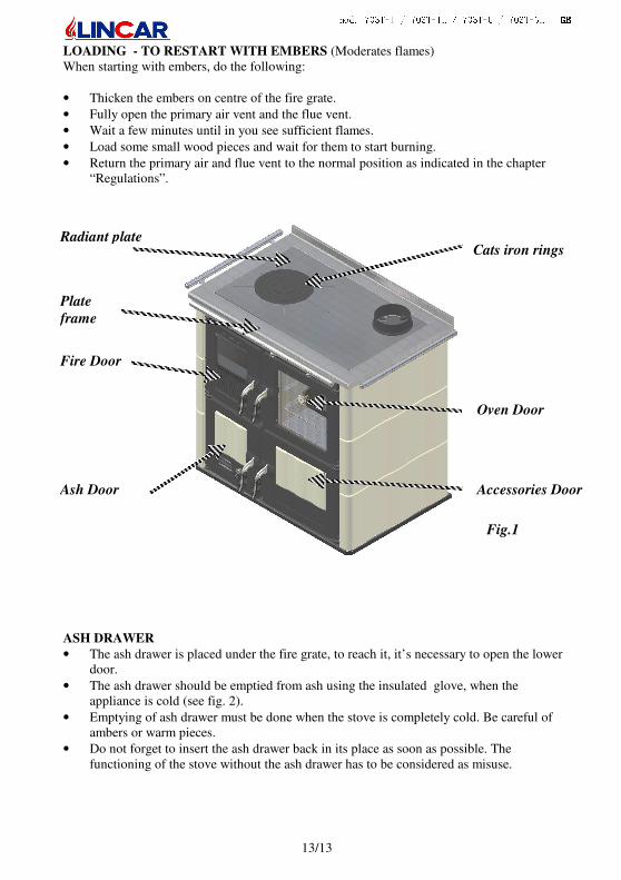
Oven Door
Accessories Door Ash Door
Fig.1
Cats iron rings
Fire Door
Radiant plate
Plate
frame
mod. 703T-I / 703T-IL / 703T-G / 703T-GL GBGBGBGB
14/14
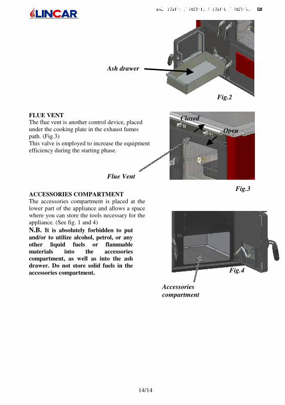
FLUE VENT The flue vent is another control device, placed under the cooking plate in the exhaust fumes path. (Fig.3) This valve is employed to increase the equipment efficiency during the starting phase.
ACCESSORIES COMPARTMENT
The accessories compartment is placed at the lower part of the appliance and allows a space where you can store the tools necessary for the appliance. (See fig. 1 and 4)
N.B. It is absolutely forbidden to put
and/or to utilize alcohol, petrol, or any
other liquid fuels or flammable
materials into the accessories
compartment, as well as into the ash
drawer. Do not store solid fuels in the
accessories compartment.
Open
Closed
Flue Vent
Fig.2
Fig.3
Accessories
compartment
Ash drawer
Fig.4
mod. 703T-I / 703T-IL / 703T-G / 703T-GL GBGBGBGB
15/15
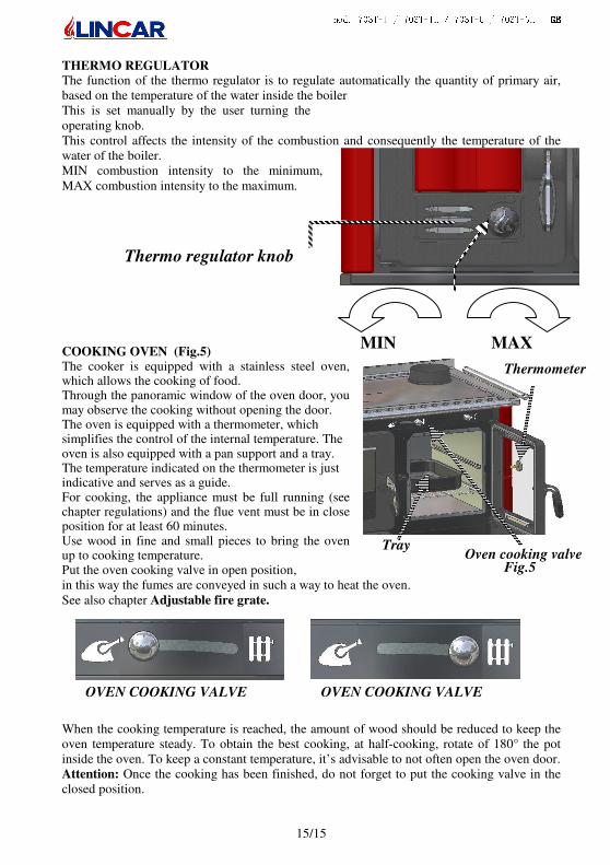
THERMO REGULATOR The function of the thermo regulator is to regulate automatically the quantity of primary air, based on the temperature of the water inside the boiler This is set manually by the user turning the operating knob. This control affects the intensity of the combustion and consequently the temperature of the water of the boiler. MIN combustion intensity to the minimum, MAX combustion intensity to the maximum.
COOKING OVEN (Fig.5) The cooker is equipped with a stainless steel oven, which allows the cooking of food. Through the panoramic window of the oven door, you may observe the cooking without opening the door. The oven is equipped with a thermometer, which simplifies the control of the internal temperature. The oven is also equipped with a pan support and a tray. The temperature indicated on the thermometer is just indicative and serves as a guide. For cooking, the appliance must be full running (see chapter regulations) and the flue vent must be in close position for at least 60 minutes. Use wood in fine and small pieces to bring the oven up to cooking temperature. Put the oven cooking valve in open position, in this way the fumes are conveyed in such a way to heat the oven. See also chapter Adjustable fire grate.
When the cooking temperature is reached, the amount of wood should be reduced to keep the oven temperature steady. To obtain the best cooking, at half-cooking, rotate of 180° the pot inside the oven. To keep a constant temperature, it’s advisable to not often open the oven door. Attention: Once the cooking has been finished, do not forget to put the cooking valve in the closed position.
Tray
Thermometer
Oven cooking valve Fig.5
OVEN COOKING VALVE OVEN COOKING VALVE
MIN
Thermo regulator knob
MAX
mod. 703T-I / 703T-IL / 703T-G / 703T-GL GBGBGBGB
16/16
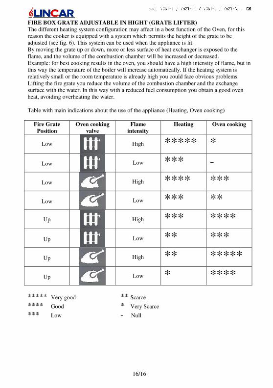
FIRE BOX GRATE ADJUSTABLE IN HIGHT (GRATE LIFTER)
The different heating system configuration may affect in a best function of the Oven, for this reason the cooker is equipped with a system which permits the height of the grate to be adjusted (see fig. 6). This system can be used when the appliance is lit. By moving the grate up or down, more or less surface of heat exchanger is exposed to the flame, and the volume of the combustion chamber will be increased or decreased. Example: for best cooking results in the oven, you should have a high intensity of flame, but in this way the temperature of the boiler will increase automatically. If the heating system is relatively small or the room temperature is already high you could face obvious problems. Lifting the fire grate you reduce the volume of the combustion chamber and the exchange surface with the water. In this way with a reduced fuel consumption you obtain a good oven heat, avoiding overheating the water. Table with main indications about the use of the appliance (Heating, Oven cooking)
Fire Grate
Position
Oven cooking
valve
Flame
intensity
Heating Oven cooking
Low
High ***** *
Low
Low *** -
Low
High **** ***
Low
Low *** **
Up
High *** ****
Up
Low ** ***
Up
High ** *****
Up
Low * ****
***** Very good ** Scarce
**** Good * Very Scarce *** Low - Null
mod. 703T-I / 703T-IL / 703T-G / 703T-GL GBGBGBGB
17/17
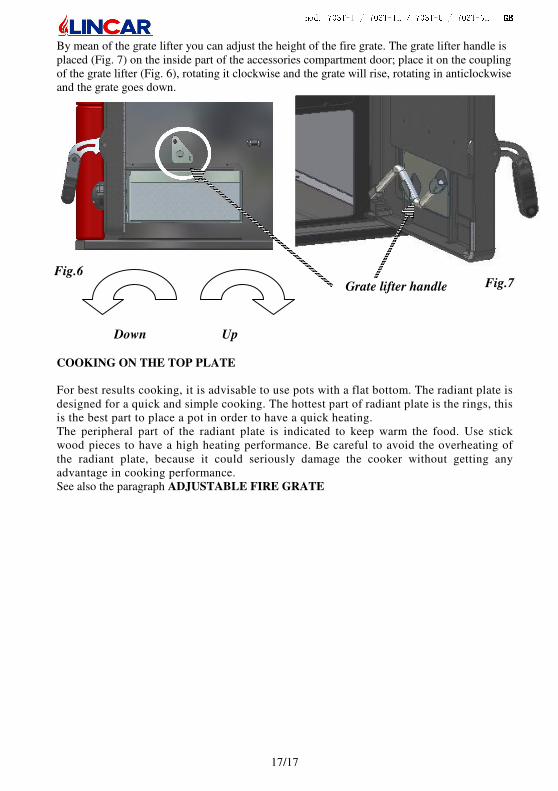
By mean of the grate lifter you can adjust the height of the fire grate. The grate lifter handle is placed (Fig. 7) on the inside part of the accessories compartment door; place it on the coupling of the grate lifter (Fig. 6), rotating it clockwise and the grate will rise, rotating in anticlockwise and the grate goes down.
COOKING ON THE TOP PLATE For best results cooking, it is advisable to use pots with a flat bottom. The radiant plate is designed for a quick and simple cooking. The hottest part of radiant plate is the rings, this is the best part to place a pot in order to have a quick heating. The peripheral part of the radiant plate is indicated to keep warm the food. Use stick wood pieces to have a high heating performance. Be careful to avoid the overheating of the radiant plate, because it could seriously damage the cooker without getting any advantage in cooking performance. See also the paragraph ADJUSTABLE FIRE GRATE
Grate lifter handle Fig.7 Fig.6
Up Down
mod. 703T-I / 703T-IL / 703T-G / 703T-GL GBGBGBGB
18/18
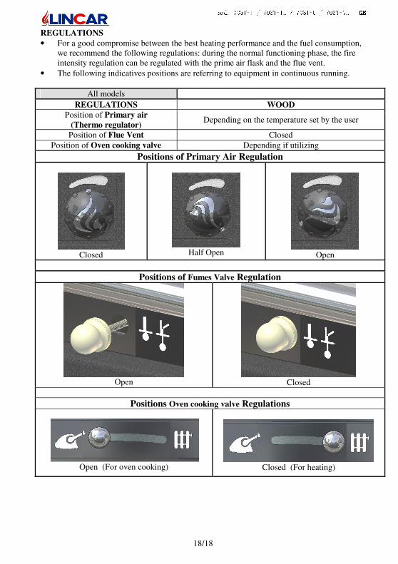
REGULATIONS
• For a good compromise between the best heating performance and the fuel consumption, we recommend the following regulations: during the normal functioning phase, the fire intensity regulation can be regulated with the prime air flask and the flue vent.
• The following indicatives positions are referring to equipment in continuous running.
All models
REGULATIONS WOOD
Position of Primary air
(Thermo regulator) Depending on the temperature set by the user
Position of Flue Vent Closed
Position of Oven cooking valve Depending if utilizing
Positions of Primary Air Regulation
Closed
Half Open
Open
Positions of Fumes Valve Regulation
Open
Closed
Positions Oven cooking valve Regulations
Open (For oven cooking)
Closed (For heating)
mod. 703T-I / 703T-IL / 703T-G / 703T-GL GBGBGBGB
19/19
3 MAINTENANCE AND CLEANING
RESERVED TO USER
Important warnings
• Any maintenance and cleaning operation must be done when the appliance is switched off and cold.
• In case the appliance is not utilized for a longer period, before putting it in function, it is advisable to control that the fume evacuation conducts are not obstructed. Carry out the ordinary/extraordinary maintenance and check the correct functioning of all devices connected to the appliance or to the heating plant.
• Any control must be carried out by qualified person only.
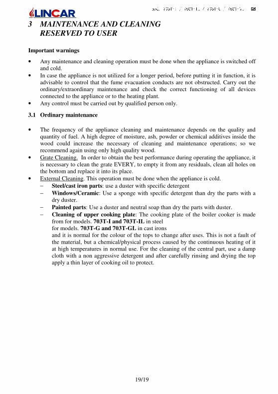
3.1 Ordinary maintenance
• The frequency of the appliance cleaning and maintenance depends on the quality and quantity of fuel. A high degree of moisture, ash, powder or chemical additives inside the wood could increase the necessary of cleaning and maintenance operations; so we recommend again using only high quality wood.
• Grate Cleaning. In order to obtain the best performance during operating the appliance, it is necessary to clean the grate EVERY, to empty it from any residuals, clean all holes on the bottom and replace it into its place.
• External Cleaning. This operation must be done when the appliance is cold.
− Steel/cast iron parts: use a duster with specific detergent
− Windows/Ceramic: Use a sponge with specific detergent than dry the parts with a dry duster.
− Painted parts: Use a duster and neutral soap than dry the parts with duster.
− Cleaning of upper cooking plate: The cooking plate of the boiler cooker is made from for models. 703T-I and 703T-IL in steel for models. 703T-G and 703T-GL in cast irons and it is normal for the colour of the tops to change after uses. This is not a fault of the material, but a chemical/physical process caused by the continuous heating of it at high temperatures in normal use. For the cleaning of the central part, use a damp cloth with a non aggressive detergent and after carefully rinsing and drying the top apply a thin layer of cooking oil to protect.
mod. 703T-I / 703T-IL / 703T-G / 703T-GL GBGBGBGB
20/20
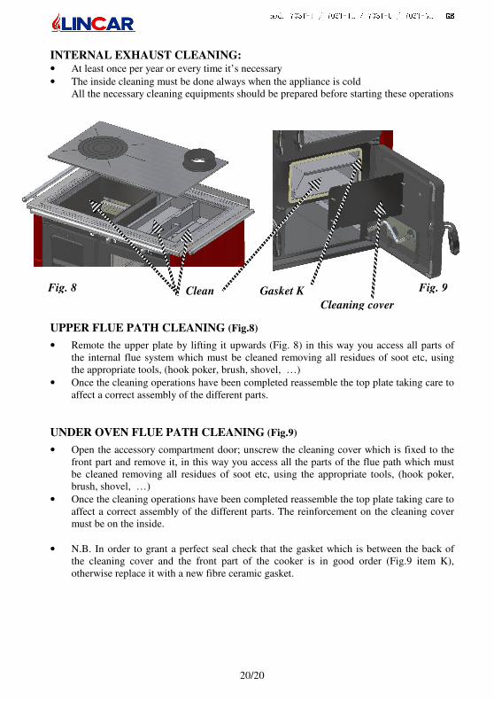
INTERNAL EXHAUST CLEANING: • At least once per year or every time it’s necessary • The inside cleaning must be done always when the appliance is cold
All the necessary cleaning equipments should be prepared before starting these operations
UPPER FLUE PATH CLEANING (Fig.8)
• Remote the upper plate by lifting it upwards (Fig. 8) in this way you access all parts of the internal flue system which must be cleaned removing all residues of soot etc, using the appropriate tools, (hook poker, brush, shovel, …)
• Once the cleaning operations have been completed reassemble the top plate taking care to affect a correct assembly of the different parts.
UNDER OVEN FLUE PATH CLEANING (Fig.9)
• Open the accessory compartment door; unscrew the cleaning cover which is fixed to the front part and remove it, in this way you access all the parts of the flue path which must be cleaned removing all residues of soot etc, using the appropriate tools, (hook poker, brush, shovel, …)
• Once the cleaning operations have been completed reassemble the top plate taking care to affect a correct assembly of the different parts. The reinforcement on the cleaning cover must be on the inside.
• N.B. In order to grant a perfect seal check that the gasket which is between the back of the cleaning cover and the front part of the cooker is in good order (Fig.9 item K), otherwise replace it with a new fibre ceramic gasket.
Fig. 8 Fig. 9 Clean Gasket K
Cleaning cover

mod. 703T-I / 703T-IL / 703T-G / 703T-GL GBGBGBGB
21/21
3.2 Annual maintenance (by qualified person)
• EVERY YEAR IS RECOMMENDED THE FOLLOWING OPERATIONS MAINTENANCE:
− Complete check up of the appliance by a qualified person.
− Cleaning of exhaust gas and flue pipes.
− To check and replace seals as required.
− To check the flue seal.
• We recommend to stipulate a contract with an after-sales service 3.3 Accessories
The following accessories are supplied with the appliance:
• To move residuals into the combustion chamber and to move ash-drawer.
• For warm parts
• For handling the grate lifter
mod. 703T-I / 703T-IL / 703T-G / 703T-GL GBGBGBGB
22/22
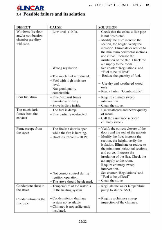
3.4 Possible failure and its solution
DEFECT CAUSE SOLUTION
Windows fire door and/or combustion chamber are dirty with soot.
− Low draft <10 Pa.
− Wrong regulation.
− Too much fuel introduced.
− Fuel with high moisture level.
− Not good quality combustible.
− Check that the exhaust flue pipe is not obstructed.
− Modify the flue: increase the section, the height, verify the isolation. Eliminate or reduce to the minimum horizontal sections and curve. Increase the insulation of the flue. Check the air supply to the room.
− See charter “Regulations” and “Fuel to be utilized”
− Reduce the quantity of fuel. − Use dry and weathered wood
only. − Read charter “Combustibile”.
Poor fuel draw − Flue / exhaust fumes unsuitable or dirty.
− Stove is dirty inside.
− Require chimney sweep intervention.
− Clean the stove.
Too much dark fumes from the exhaust
− The fuel is damp.
− Flue partially obstructed.
− Use weathered and better quality of wood.
− Call the assistance service/ chimney sweep.
Fume escape from the stove
− The fire/ash door is open while the fire is burning.
− Draft insufficient <10 Pa.
− Not correct control during ignition operation
− The stove should be cleaned.
− Verify the correct closure of the doors and the seal of the gaskets
− Modify the flue: increase the section, the height, verify the isolation. Eliminate or reduce to the minimum horizontal sections and curve. Increase the insulation of the flue. Check the air supply to the room.
− Require chimney sweep intervention.
− See charter “Regulations” and “Fuel to be utilized”
− Clean the stove
Condensate close to the stove
Condensation on the flue pipe
− Temperature of the water is in the heating system.
− Condensateion drainage system not available
− Chimney is not sufficiently insulated.
− Regulate the water temperature pump to start > 55°C
− Require a chimney sweep inspection of the chimney.
mod. 703T-I / 703T-IL / 703T-G / 703T-GL GBGBGBGB
23/23
Every intervention has be done by a qualified person !
Lincar S.p.A is not responsible for damages to things or people due to a wrong installation, equipment tampering, improper use, bad maintenance or no observation of laws. If considerate appropriate, Lincar spa reserves the right to make modifications without notice and in every moment. Some particulars and accessories illustrated in this handbook are not mass produced item so its extra costs are to check at contract release.
mod. 703T-I / 703T-IL / 703T-G / 703T-GL GBGBGBGB
24/24
Note:_______________________________________________________________________ ___________________________________________________________________________ ___________________________________________________________________________ ___________________________________________________________________________ ___________________________________________________________________________ ___________________________________________________________________________ ___________________________________________________________________________ ___________________________________________________________________________ ___________________________________________________________________________ ___________________________________________________________________________ ___________________________________________________________________________ ___________________________________________________________________________ ___________________________________________________________________________ ___________________________________________________________________________ ___________________________________________________________________________ ___________________________________________________________________________ ___________________________________________________________________________ ___________________________________________________________________________ ___________________________________________________________________________ ___________________________________________________________________________ ___________________________________________________________________________ ___________________________________________________________________________ ___________________________________________________________________________ ___________________________________________________________________________
mod. 703T-I / 703T-IL / 703T-G / 703T-GL GBGBGBGB
25/25
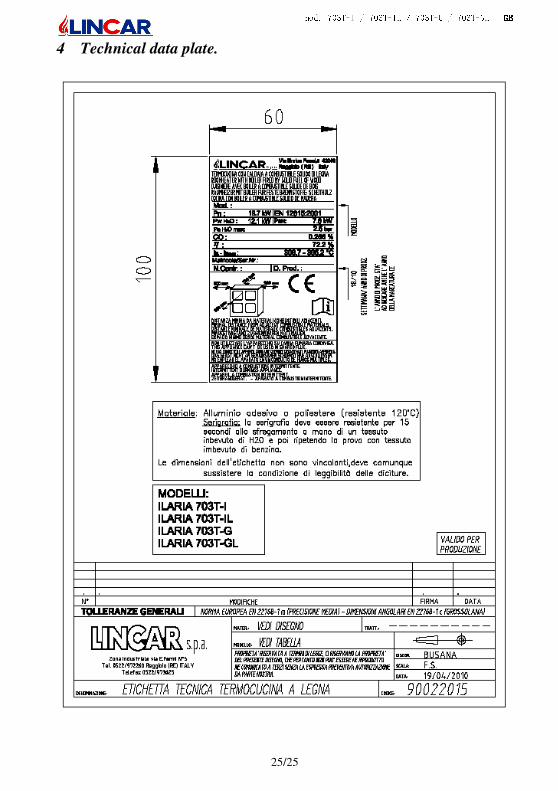
4 Technical data plate.

mod. 703T-I / 703T-IL / 703T-G / 703T-GL GBGBGBGB
26/26
Lincar S.p.A. Via E. Fermi, 5 – 42046 Reggiolo (RE) – Italy – Tel. +39 0522 972260 – Fax +39 0522 973625
www.lincar.it - [email protected]