Embed Size (px)
Citation preview
We reserve the right to modify technical specifications without prior notice.83025000cUK – translation of the operating manual © ait-deutschland GmbH
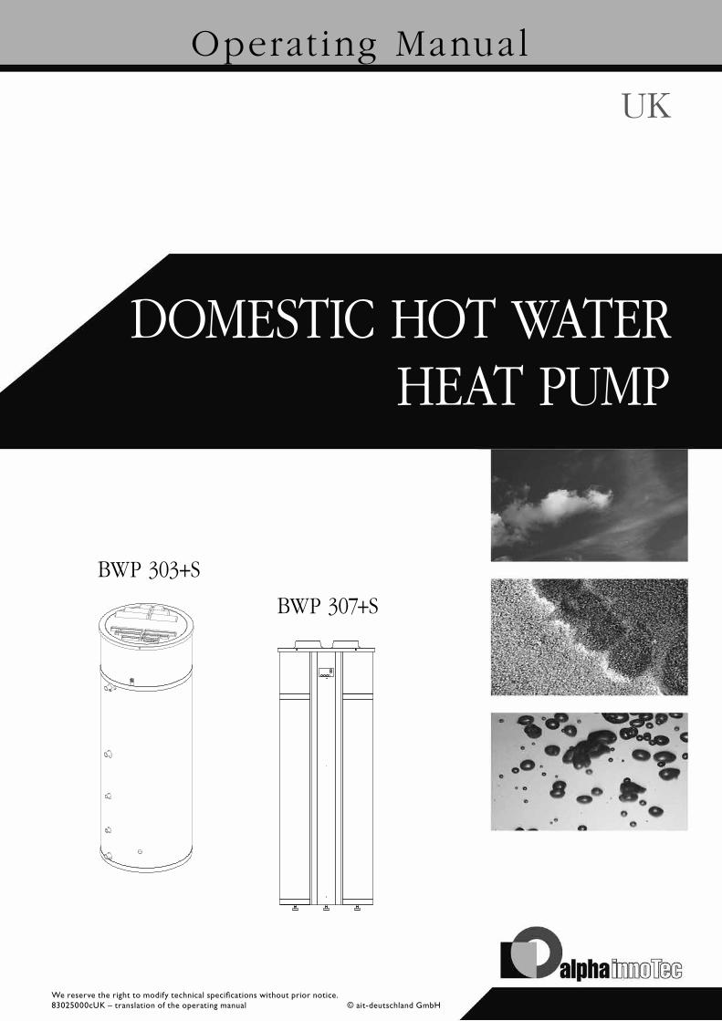
HEAT PUMP
Operat ing Manual
DOMESTIC HOT WATER
UK
BWP 307+S
BWP 303+S
2We reserve the right to modify technical specifications without prior notice.
83025000cUK – translation of the operating manu-al © ait-deutschland GmbH
Please read firstThis operating manual provides important information on handling the unit. It is an integral part of the product and must be stored so that it is accessible in the immediate vicinity of the unit. It must remain available throughout the entire service life of the unit. It must be handed over to subsequent owners or users of the unit.
Read the operating manual before working on or operating the unit. This applies in particular to the chapter on safety. Always follow all instructions completely and without restrictions.
It is possible that this operating manual may contain instructions that seem incomprehensible or unclear. In the event of any questions or if any details are unclear, contact the factory customer service department or the manufacturer’s local partner.
As this operating manual possibly has been written for several different models, always comply with the parameters for the respective model.
This operating manual is intended only for persons assigned to work on or with the unit. Treat all constituent parts confidentially. The information contained herein is protected by copyright. No part of this manual may be reproduced, transmitted, copied, stored in electronic data systems or translated into another language, either wholly or in part, without the express written permission of the manufacturer.
SymbolsThe following symbols are used in the operating manual. They have the following meaning:
Information for users.
Information or instructions for qualified personnel.
DANGER! Indicates a direct impending danger
resulting in severe injuries or death.
WARNING! Indicates a potentially dangerous situation
that could result in serious injuries or death.
CAUTION! Indicates a potentially dangerous situation
that could result in medium or slight injuries.
ATTENTION Indicates a potentially dangerous situation, which
could result in property damage.
NOTE. Emphasized information.
€ ENERGY SAVING TIP Indicates suggestions that help to save energy,
raw materials and costs.
Reference to other sections of the operating manual.
Reference to other documents of the manufacturer.
3
Contents
INFORMATION FOR USERS AND QUALIFIED PERSONNEL
PLEASE READ FIRST ..................................................................2
SYMBOLS .....................................................................................2
INTENDED USE ..........................................................................4
DISCLAIMER................................................................................4
EC CONFORMITY .....................................................................4
SAFETY .........................................................................................4
AREA OF USE ..............................................................................5
CARE OF THE UNIT ..................................................................5
MALFUNCTIONS .......................................................................6
CUSTOMER SERVICE ................................................................6
WARRANTY / GUARANTEE ....................................................6
DISPOSAL ....................................................................................6
DESCRIPTION OF UNIT ..........................................................6The unit ..................................................................................6How it works .........................................................................6Functional Princible ..............................................................7
INSTRUCTIONS FOR QUALIFIED PERSONNEL
SCOPE OF DELIVERY ......................................................8
INSTALLATION AND ASSEMBLY ...........................................8
COMMISSIONING ...................................................................14
MAINTENANCE OF THE UNIT .............................................14
REMOVING AND ATTACHING THE SCREEN .................. 17
ACCESS TO THE COOLING CIRCUIT ................................18
OPERATION
BWP 307+S - THE CONTROL UNIT ....................................20Operation .............................................................................20USER MENU .......................................................................20OPERATING MENU ...........................................................21Setpoints...............................................................................25DEFROST TABLE ................................................................26
FUNCTION ...............................................................................26POWER ................................................................................26WATER HEATING ..............................................................26FAN MODE ..........................................................................26DEFROSTING .....................................................................27ADDITIONAL CAPACITY ................................................27OPERATING SAFETY ........................................................27HIGH-PRESSURE LIMITER ...............................................27ALARM .................................................................................27
BUILT-IN SAFETY DEVICES ...................................................27SAFETY TEMPERATURE LIMITERS FOR THE HEATING
CARTRIDGE ..................................................................27
TROUBLESHOOTING .............................................................28
INSTRUCTIONS FOR QUALIFIED PERSONNEL
TECHNICAL DATA / SCOPE OF DELIVERY ..............30
FREE PRESSURE / AIR FLOW RATE .......................................31BWP 303+S / BWP 307+S ..................................................31
DIMENSIONED DRAWING ...................................................32
BWP 307+S ...............................................................................32
BWP 303+S.................................................................................33
INSTALLATION PLAN BWP 307+S / BWP 303+S .............34
COOLING CIRCUIT ................................................................35Hydraulic diagram ...............................................................36Integration with external solar system ...........................37Integration with second heat generator .........................38
APPENDIX
OVERVIEW OF THE SET VALUES .........................................41
EC DECLARATION OF CONFORMITY ............................. 44
We reserve the right to modify technical specifications without prior notice.83025000cUK – translation of the operating manu-
al © ait-deutschland GmbH
4We reserve the right to modify technical specifications without prior notice.
83025000cUK – translation of the operating manu-al © ait-deutschland GmbH
Intended useThe unit may be used only for the intended purpose. This means:
• for domestic water heating.
The unit may be operated only within its technical parameters.
“Technical data / scope of delivery“.
DisclaimerThe manufacturer is not liable for losses resulting from any use of the unit which is not its intended use.
The manufacturer’s liability also expires:
• if work is carried out on the unit and its components contrary to the instructions in this operating manual.
• if work is improperly carried out on the unit and its components,
• if work is carried out on the unit which is not described in this operating manual, and this work has not been explicitly approved by the manufacturer in writing.
• if the unit or components in the unit have been altered, modified or removed without the explicit written consent of the manufacturer.
EC conformityThe unit bears the CE mark of conformity.
“EC declaration of conformity”.
SafetyThe unit is safe to operate for its intended use. The construction and design of the unit conform to current state of the art standards, all relevant DIN/VDE regulations and all relevant safety regulations.
Every person who performs work on the unit must have read and understood the operating manual prior to starting any work. This also applies if the respective person has already worked with such a unit or a similar unit or has been trained by the manufacturer.
Every person who performs work on the unit must comply with the applicable accident prevention and safety regulations. This applies in particular to the wearing of personal protective equipment.
ATTENTION Only install the heating pump indoors. Maintain minimum clearances.
“Dimensioned drawings” and “installation plan”.
ATTENTION Store unit in packaging and upright, not filled
with water. Transport unit in packaging and not filled with
water. Ambient temperature for storage and transport:
-10 °C to +50 °C.
ATTENTION Do not tilt the unit more than a maximum of 45°
(in any direction). The unit can be substantially damaged if tilted by
more than 45°!
ATTENTION Do not drill holes in the shell of the unit (i.e. for
fittings). This could damage the unit to the point of making it unserviceable.
5We reserve the right to modify technical specifications without prior notice.
83025000cUK – translation of the operating manu-al © ait-deutschland GmbH
DANGER! Risk of fatal electric shock! Electrical connection work must be
carried out by qualified electricians only.
– Before working on the unit, disconnect the power supply, disconnect the unit from the power supply (unplug!) and secure against being switched back on again. Note that the fan may continue to turn even after the unit has been switched off.
DANGER! During installation and while carrying out
electrical work, comply with the relevant EN‑, VDE and/or local safety regulations.
DANGER! Qualified trained personnel only (qualified
heating, cooling system, refrigeration or refrigerant technician or electrician) may carry out work on the unit and its components.
WARNING! Unit contains refrigerants! Qualified
service personnel must ensure that prior to maintenance or repairs of parts that circulate refrigerant, the refrigerant must be removed to the extent necessary for carrying out the work safely.
Leaking refrigerant could result in personal injury or environmental damage. Therefore:
– Switch off system,– Notify the manufacturer’s authorised
service centre.
WARNING! Use only water that is suitable for drinking
in accordance with the drinking water ordinance.
Ensure that all drinking water connections comply with the local regulations.
Use only suitable materials for the entire domestic water circuit.
In case of excessive water pressure, install a suitable pressure reduction valve in the cold water supply pipe.
Area of useTaking into account the ambient conditions, use limits and the relevant regulations, the pump can be used in new or existing domestic hot water systems.
“Technical data / Scope of delivery”.
Care of the unitYou can clean the outer surfaces of the unit with a damp cloth and proprietary household cleaning products.
Do not use cleaning or care products that contain abrasives, acids and/or chlorine. Such products would destroy the surfaces and could also damage the technical components of the unit.
6We reserve the right to modify technical specifications without prior notice.
83025000cUK – translation of the operating manu-al © ait-deutschland GmbH
MalfunctionsMalfunctions are indicated by the controller on the unit.
DANGER! Only customer service personnel
authorised by the manufacturer may carry out service and repair work on the unit’s components.
“Customer service”.
Note that no malfunction is displayed if the safety temperature limiter on the electric heating element has tripped.
“Installed safety devices”, “Safety temperature limiter” section.
Customer serviceFor technical information please contact your local heating engineer or the manufacturer’s local partner.For a current list and additional partners of the manufac-turer, please visit
DE: www.alpha-innotec.deEU: www.alpha-innotec.com
Warranty / GuaranteeFor warranty and guarantee conditions, please refer to the purchase documents.
NOTE: Please contact your dealer about all matters con-
cerning warranties and guarantees.
DisposalIf taking the old unit out of service, comply with the relevant local laws, guidelines, directives and standards for the recovery, reuse, recycling and disposal of resources and components of cooling units.
“Dismantling”.
Description of unit
THE UNIT
The BWP is a ready-to-connect, domestic water heat pump. It consists of the housing, the components of the refrigerant, air and water circuit and all control and monitoring devices required for automatic operation.
The BWP uses the heat of the extract air to heat domestic water. During peak load period, extra power is supplied by an integrated electric heating element of 1.5 kW.
A thermowell is installed in the storage tank, which can be used for an external storage tank thermostat or a sensor (diameter 6 mm) of an external control.
The area of application and functional principle of the heat pump is specified in the operating manual.
HOW IT WORKS
The control unit starts the compressor shortly after hot water has been used. The compressor carries on running until the whole tank has once again been heated to the set temperature. In general the BWP can produce enough hot water to cover the requirements of a 4-person household (user dependent).
If the situation arises that the BWP cannot produce enough hot water, an electric heating element installed in the storage tank can be switched on. This enables more domestic water to be heated. It is possible to set the required temperature, to which the electric heating element is to heat the domestic water. Only use the electric heating element if it is needed, because the electric heating element consumes more energy than the compressor. The electric heating element must be switched on manually at the control.
“Technical data/scope of delivery”.
7We reserve the right to modify technical specifications without prior notice.
83025000cUK – translation of the operating manu-al © ait-deutschland GmbH
FUNCTIONAL PRINCIBLE
THE REFRIGERANT CIRCUIT - DESCRIPTION
The cooling system is used to optimise the heat in the extracted air. In this way the recovered heat is transfer-red to the water. This process is only possible by exter-nal supply of energy into the compressor.
The refrigerant circuit is a closed system, in which the HCFC-free refrigerant R134a functions as an energy car-rier.
In the evaporator, heat is extracted from the air at a low evaporating temperature and is transferred to the refri-gerant. The vaporous refrigerant is drawn in by a com-pressor, is compressed to a higher pressure and tempe-rature level and is transported to the liquefier, which is attached to the outside of the storage tank. Here the heat absorbed in the evaporator and part of the absor-bed compressor energy are transferred to the domestic hot water.
The high condensing pressure is then relaxed by means of an expansion device (expansion valve) to the evapora-tion pressure, and the refrigerant in the evaporator can then once again absorb heat from the exhaust air
“Cooling circuit”.
THE WATER CIRCUIT - DESCRIPTION
The water circuit is set up in compliance with the rele-vant standards and requirements.
Only water of drinking quality (according to the drinking water regulations) may be used. Ensure material compa-tibility in the whole water circuit. A suitable pressure re-ducer must be used if the water pressures are too high.
WATER CIRCUIT REQUIREMENTS
The nominal diameters of the pipes for on site installa-tion are to be defined on site, taking into account the available water pressure and the expected pressure los-ses in the pipe system. The water side installation must be according to DIN 1988. The water pipes can be fixed or flexible pipes.
Attention must be paid to the corrosivity of the mate-rials used in the pipe system to avoid damage. This re-quires particular attention if zinc coated components containing copper are used.
As with all pressure vessels, the domestic hot water tank of the water pump must be equipped with a type-tested safety valve and a non-return valve (on site).
The cold water pipe inlet is at the rear, near the floor (3/4” RG). The maximum operating pressure is 10 bar; the maximum operating temperature is 65° C. If neces-sary, a drinking water filter and a pressure reducing valve should be installed in the supply pipe.
We recommend checking the water connection sockets for dirt.
Avoid getting dirt in the pipe system when laying the pi-ping on site (if necessary, flush the pipes before connec-ting the heat pump)!
If a circulation pipe is not connected to the heat pump the connection must be appropriately sealed!
DEFROSTING (BWP 307+S ONLY)
If the temperature difference between the cooling surface temperature upstream of the cooling surface and the cooling surface temperature becomes too large, which happens if ice has formed on the cooling surface, the system begins to defrost (see diagram). Solenoid valve MA 4 opens, the exhaust air fans switch off until the ice has melted and the cooling surface has reached a temperature of approx. 5°C (depends on the setting), after which the solenoid valve closes again and the exhaust air fan restarts.
“Cooling circuit”.
Incidentally:
Your decision to purchase a domestic hot water heat pump is a long-term contribution to protecting the environment through low emissions and reduced primary energy use.
€ ENERGY SAVING TIP Do not set the domestic hot water temperature
higher than necessary. The unit operates most efficiently at low domestic hot water temperatures (≈ 45 °C).
Switch on the electric heating element only if it is actually needed. Switching on the electric heating element increases the power consumption of the unit.
8We reserve the right to modify technical specifications without prior notice.
83025000cUK – translation of the operating manu-al © ait-deutschland GmbH
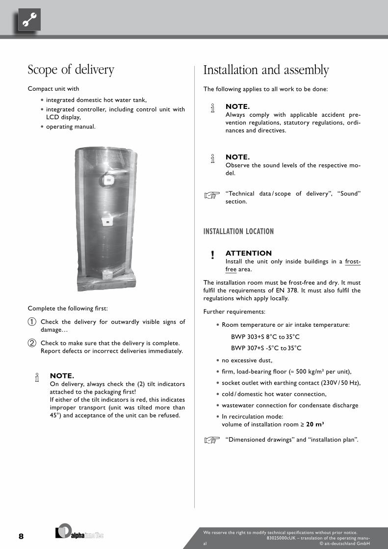
Scope of deliveryCompact unit with
• integrated domestic hot water tank,
• integrated controller, including control unit with LCD display,
• operating manual.
Complete the following first:
Check the delivery for outwardly visible signs of damage…
Check to make sure that the delivery is complete. Report defects or incorrect deliveries immediately.
NOTE. On delivery, always check the (2) tilt indicators
attached to the packaging first! If either of the tilt indicators is red, this indicates
improper transport (unit was tilted more than 45°) and acceptance of the unit can be refused.
Installation and assemblyThe following applies to all work to be done:
NOTE. Always comply with applicable accident pre-
vention regulations, statutory regulations, ordi-nances and directives.
NOTE. Observe the sound levels of the respective mo-
del.
“Technical data / scope of delivery”, “Sound” section.
INSTALLATION LOCATION
ATTENTION Install the unit only inside buildings in a frost-
free area.
The installation room must be frost-free and dry. It must fulfil the requirements of EN 378. It must also fulfil the regulations which apply locally.
Further requirements:
• Room temperature or air intake temperature:
BWP 303+S 8°C to 35°C
BWP 307+S -5°C to 35°C
• no excessive dust,
• firm, load-bearing floor (≈ 500 kg/m² per unit),
• socket outlet with earthing contact (230V / 50 Hz),
• cold / domestic hot water connection,
• wastewater connection for condensate discharge
• In recirculation mode: volume of installation room ≥ 20 m3
“Dimensioned drawings” and “installation plan”.
9We reserve the right to modify technical specifications without prior notice.
83025000cUK – translation of the operating manu-al © ait-deutschland GmbH
TRANSPORT TO INSTALLATION LOCATION
Always comply with the following safety information during transport:
DANGER! Several people are required to transport
the unit. Do not underestimate the weight of the unit.
“Technical data / Scope of delivery”, “General unit data” section.
DANGER! Danger of tipping over during transport!
This can result in personal injury and damage to the unit.
– Take suitable precautions to prevent the risk of tipping over.
ATTENTION Never use components and hydraulic connec-
tions on the unit for transport purposes. The top part of the unit (upper sheet metal ja-
cket) is not suitable for lifting.
ATTENTION Do not damage the hydraulic connections under
any circumstances.
ATTENTION Do not tilt the unit more than a maximum of 45°
(in any direction). The unit can be substantially damaged if tilted by
more than 45°.
To avoid damage during transport, you should transport the unit to its final installation location in its original packaging (on the wooden pallet) using a forklift or pallet truck.
If it is not possible to transport the unit to its final installation location using a forklift or pallet truck, you can also transport the heat pump using a hand truck.
TRANSPORT WITH A HAND TRUCK
Proceed as follows:
Push hand truck under the unit and transport carefully to installation location.
ATTENTION Transport unit with the hand truck only on the
corresponding transport pallet. This also applies to carrying up and down steps.
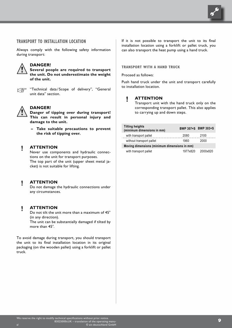
Tilting heights (minimum dimensions in mm) BWP 307+S BWP 303+S
with transport pallet 2080 2100without transport pallet 1960 2000
Moving dimensions (minimum dimensions in mm)with transport pallet 1977x820 2000x820
10We reserve the right to modify technical specifications without prior notice.
83025000cUK – translation of the operating manu-al © ait-deutschland GmbH
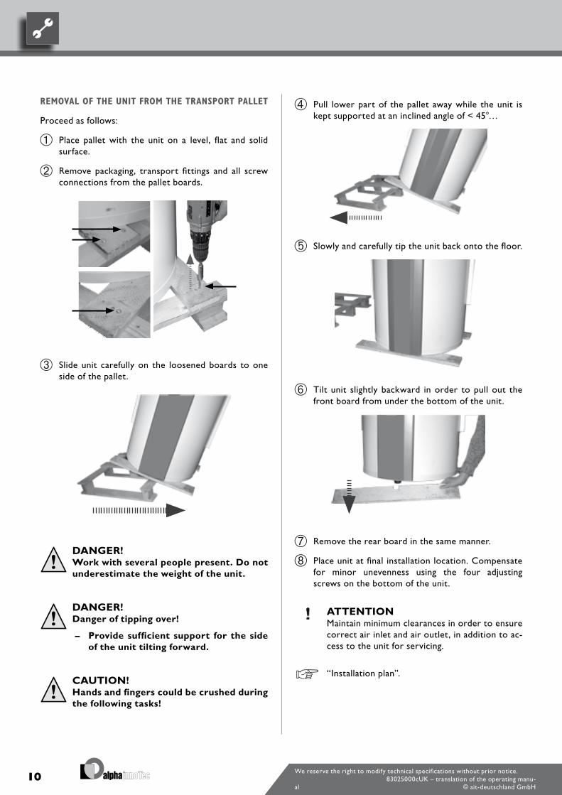
Pull lower part of the pallet away while the unit is kept supported at an inclined angle of < 45°…
Slowly and carefully tip the unit back onto the floor.
Tilt unit slightly backward in order to pull out the front board from under the bottom of the unit.
Remove the rear board in the same manner.
Place unit at final installation location. Compensate for minor unevenness using the four adjusting screws on the bottom of the unit.
ATTENTION Maintain minimum clearances in order to ensure
correct air inlet and air outlet, in addition to ac-cess to the unit for servicing.
“Installation plan”.
REMOVAL OF THE UNIT FROM THE TRANSPORT PALLET
Proceed as follows:
Place pallet with the unit on a level, flat and solid surface.
Remove packaging, transport fittings and all screw connections from the pallet boards.
Slide unit carefully on the loosened boards to one side of the pallet.
DANGER! Work with several people present. Do not
underestimate the weight of the unit.
DANGER! Danger of tipping over!
– Provide sufficient support for the side of the unit tilting forward.
CAUTION! Hands and fingers could be crushed during
the following tasks!
11We reserve the right to modify technical specifications without prior notice.
83025000cUK – translation of the operating manu-al © ait-deutschland GmbH
INSTALLATION /CONNECTION TO THE DOMESTIC WATER CIRCUIT
DANGER! Risk of fatal electric shock!
Before working on the unit, disconnect the power supply, disconnect the unit from the power supply (unplug!) and secure against being switched back on again. Note that the fan may continue to turn even after the unit has been switched off.
Connect the domestic hot water tank according to DIN 1988 and DIN 4753, Part 1 (or the applicable local standards, guidelines and directives).
ATTENTION Connect the unit to the hot water circuit accor-
ding to the hydraulic diagram.
“Hydraulic diagram”.
NOTE. The installation must be sufficiently dimensioned
in connection with the existing water pressure and the expected pressure loss, in order to en-sure sufficient water pressure and a sufficient water supply to the tap.
Do not exceed the operating pressures specified on the rating plate.Install a pressure reduction valve and a water filter in the supply pipe, if necessary.
ATTENTION When installing the connections, always secure
the connections on the unit from twisting, in or-der to prevent damage to the copper pipes in the interior of the unit.
Flush water circuit thoroughly before connecting the unit.
NOTE: Contamination and deposits in the water circuit
can cause malfunctions.
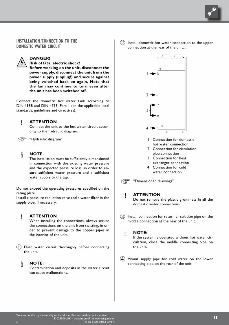
Install domestic hot water connection to the upper connection at the rear of the unit…
1 Connection for domestic hot water connection
2 Connection for circulation pipe connection
3 Connection for heat exchanger connection
4 Connection for cold water connection
“Dimensioned drawings”.
ATTENTION Do not remove the plastic grommets in all the
domestic water connections.
Install connection for return circulation pipe on the middle connection at the rear of the unit…
NOTE: If the system is operated without hot water cir-
culation, close the middle connecting pipe on the unit.
Mount supply pipe for cold water on the lower connecting pipe on the rear of the unit.
12We reserve the right to modify technical specifications without prior notice.
83025000cUK – translation of the operating manu-al © ait-deutschland GmbH
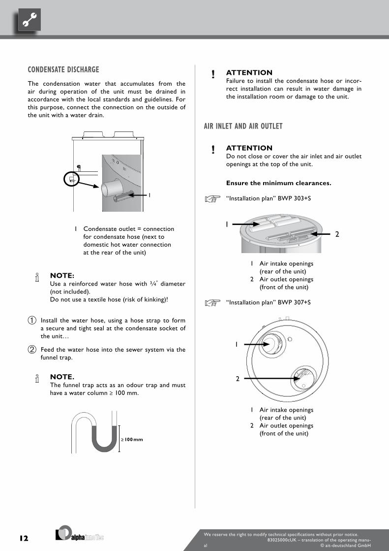
CONDENSATE DISCHARGE
The condensation water that accumulates from the air during operation of the unit must be drained in accordance with the local standards and guidelines. For this purpose, connect the connection on the outside of the unit with a water drain.
1 Condensate outlet = connection for condensate hose (next to domestic hot water connection at the rear of the unit)
NOTE: Use a reinforced water hose with 3 ⁄4” diameter
(not included). Do not use a textile hose (risk of kinking)!
Install the water hose, using a hose strap to form a secure and tight seal at the condensate socket of the unit…
Feed the water hose into the sewer system via the funnel trap.
NOTE. The funnel trap acts as an odour trap and must
have a water column ≥ 100 mm.
ATTENTION Failure to install the condensate hose or incor-
rect installation can result in water damage in the installation room or damage to the unit.
AIR INLET AND AIR OUTLET
ATTENTION Do not close or cover the air inlet and air outlet
openings at the top of the unit.
Ensure the minimum clearances.
“Installation plan” BWP 303+S
1 Air intake openings (rear of the unit)
2 Air outlet openings (front of the unit)
“Installation plan” BWP 307+S
1 Air intake openings (rear of the unit)
2 Air outlet openings (front of the unit)
13We reserve the right to modify technical specifications without prior notice.
83025000cUK – translation of the operating manu-al © ait-deutschland GmbH
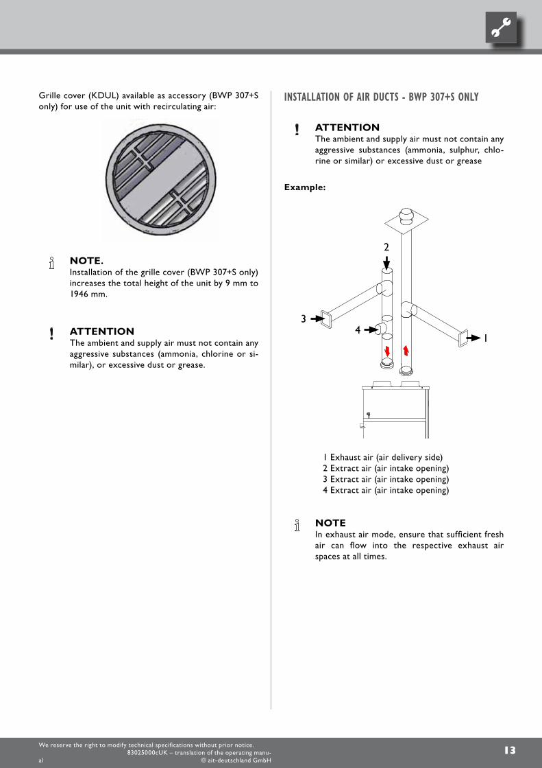
INSTALLATION OF AIR DUCTS - BWP 307+S ONLY
ATTENTION The ambient and supply air must not contain any
aggressive substances (ammonia, sulphur, chlo-rine or similar) or excessive dust or grease
Example:
1 Exhaust air (air delivery side)2 Extract air (air intake opening)3 Extract air (air intake opening)4 Extract air (air intake opening)
NOTE In exhaust air mode, ensure that sufficient fresh
air can flow into the respective exhaust air spaces at all times.
Grille cover (KDUL) available as accessory (BWP 307+S only) for use of the unit with recirculating air:
NOTE. Installation of the grille cover (BWP 307+S only)
increases the total height of the unit by 9 mm to 1946 mm.
ATTENTION The ambient and supply air must not contain any
aggressive substances (ammonia, chlorine or si-milar), or excessive dust or grease.
14We reserve the right to modify technical specifications without prior notice.
83025000cUK – translation of the operating manu-al © ait-deutschland GmbH
Then the version number of the control software appears briefly on the screen, before the screen switches to the default display, which shows the current temperature of the water in the hot water tank.
Maintenance of the unit
DANGER! Risk of fatal electric shock! All electrical
connections must be carried out by qualified electricians only.
– Before working on the unit, disconnect the power supply, disconnect the unit from the power supply (unplug!) and secure against being switched back on again. Note that the fan may continue to turn even after the unit has been switched off.
ATTENTION After the initial installation and at intervals of se-
veral days, conduct a visual inspection for any leaks in the domestic water circuit. Check regu-larly to ensure that the condensate drain is not blocked.
DOMESTIC WATER CIRCUIT AND DOMESTIC HOT WATER TANK
SAFETY VALVE
ATTENTION Ensure that the safety valve is in working order. Inspect the safety valve several times each year
to ensure that it is functioning properly and re-place, if necessary.
NOTE. The manufacturer will assume no liability for da-
mage resulting from a defective or inoperable sa-fety valve.
Commissioning
DOMESTIC HOT WATER CIRCUIT
Open cold water inlet and fill the unit’s domestic hot water tank.
Open the highest domestic hot water tap in the house or apartment and leave open under supervision until no more air escapes from the tap, and only water flows out…
Check the domestic hot water circuit for leaks, as soon as the domestic hot water tank is completely filled.
ELECTRICAL CONNECTIONS
The unit is wired ready for connection at the time of delivery. Plug the unit’s power plug into a socket outlet with earthing contact.
COOLING CIRCUIT
The unit’s cooling circuit is ready for operation at the time of delivery. No work may be performed on the cooling circuit. The unit’s electronic control unit automatically controls all functions related to operation of the compressor and the fan.
You only have to set the required domestic hot water temperature (factory setting: 50 °C).
“Operation”.
€ ENERGY SAVING TIP Do not set the domestic hot water temperature
higher than necessary. The unit operates most ef-ficiently at low domestic hot water temperatures (≈ 45 °C).
SWITCHING ON THE UNIT
When the unit is supplied with electricity (by plugging in the power plug), the display lights up and counts upward 5 seconds.
15We reserve the right to modify technical specifications without prior notice.
83025000cUK – translation of the operating manu-al © ait-deutschland GmbH
SACRIFICIAL ANODE / SENSOR POCKET
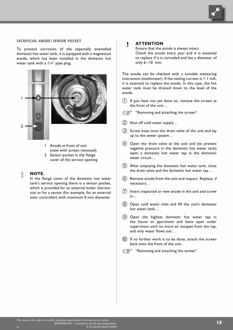
To prevent corrosion of the especially enamelled domestic hot water tank, it is equipped with a magnesium anode, which has been installed in the domestic hot water tank with a 11⁄4” pipe plug.
1 Anode at front of unit (view with screen removed)
2 Sensor pocket in the flange cover of the service opening
NOTE. In the flange cover of the domestic hot water
tank’s service opening there is a sensor pocket, which is provided for an external boiler thermo-stat or for a sensor (for example, for an external solar controller) with maximum 6 mm diameter.
ATTENTION Ensure that the anode is always intact. Check the anode every year and it is essential
to replace if it is corroded and has a diameter of only 6 – 10 mm.
The anode can be checked with a suitable measuring instrument (multimeter). If the testing current is < 1 mA, it is essential to replace the anode. In this case, the hot water tank must be drained down to the level of the anode.
If you have not yet done so, remove the screen at the front of the unit…
“Removing and attaching the screen”.
Shut off cold water supply…
Screw hose onto the drain valve of the unit and lay up to the sewer system…
Open the drain valve at the unit and (to prevent negative pressure in the domestic hot water tank) open a domestic hot water tap in the domestic water circuit…
After emptying the domestic hot water tank, close the drain valve and the domestic hot water tap…
Remove anode from the unit and inspect. Replace, if necessary…
Insert inspected or new anode in the unit and screw in…
Open cold water inlet and fill the unit’s domestic hot water tank…
Open the highest domestic hot water tap in the house or apartment and leave open under supervision until no more air escapes from the tap, and only water flows out…
If no further work is to be done, attach the screen back onto the front of the unit.
“Removing and attaching the screen”.
16We reserve the right to modify technical specifications without prior notice.
83025000cUK – translation of the operating manu-al © ait-deutschland GmbH
COMPONENTS OF THE COOLING CIRCUIT
Remove screen, plastic cover and upper sheet metal jacket from unit, in order to access the components of the cooling circuit…
After completing work on the components of the cooling circuit, re-attach the screen, plastic cover and the upper sheet metal jacket onto the unit.
“Removing and mounting the screen” and “Access to the cooling circuit”.
EVAPORATOR
The maintenance work is limited to cleaning the evaporator periodically or as needed.
CAUTION! Risk of injury due to sharp‑edged fins.
ATTENTION Do not damage fins.
Check to ensure that the fins of the evaporator are clean. Clean fins if necessary…
FAN
Clean the fan periodically or as needed, using a brush or bottle cleaner, etc.
ATTENTION Ensure that the balancing weights on the fan
wheel are not removed, as this could cause un-balance and therefore increased noise and wear of the fan.
CONDENSATE CHANNEL AND DRAIN
Inspect condensate channel and drain to ensure that they are clean.
Proceed as follows:
Pour water into the condensate channel and check whether it drains freely…
If the water does not drain freely, clean the condensate drain.
CLEANING THE DOMESTIC HOT WATER TANK
The domestic hot water tank should be cleaned once each year by qualified personnel (heating or cooling system technicians).
Follow the instructions – in the preceding section…
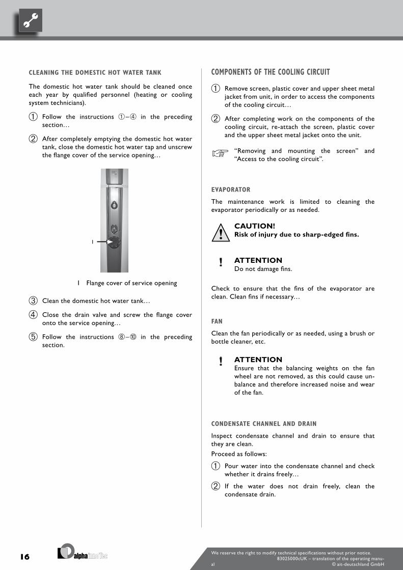
After completely emptying the domestic hot water tank, close the domestic hot water tap and unscrew the flange cover of the service opening…
1 Flange cover of service opening
Clean the domestic hot water tank…
Close the drain valve and screw the flange cover onto the service opening…
Follow the instructions – in the preceding section.
17We reserve the right to modify technical specifications without prior notice.
83025000cUK – translation of the operating manu-al © ait-deutschland GmbH
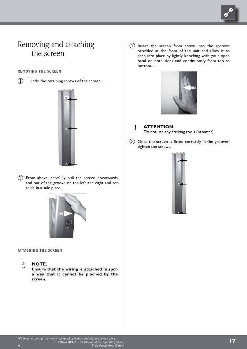
Insert the screen from above into the grooves provided at the front of the unit and allow it to snap into place by lightly knocking with your open hand on both sides and continuously from top to bottom…
ATTENTION Do not use any striking tools (hammer).
Once the screen is fitted correctly in the grooves, tighten the screws.
Removing and attaching the screen
REMOVING THE SCREEN
Undo the retaining screws of the screen…
From above, carefully pull the screen downwards and out of the groove on the left and right and set aside in a safe place.
ATTACHING THE SCREEN
NOTE. Ensure that the wiring is attached in such
a way that it cannot be pinched by the screen.
18We reserve the right to modify technical specifications without prior notice.
83025000cUK – translation of the operating manu-al © ait-deutschland GmbH
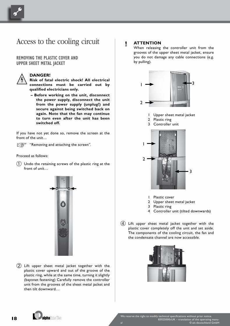
ATTENTION When releasing the controller unit from the
grooves of the upper sheet metal jacket, ensure you do not damage any cable connections (e.g. by pulling).
1 Upper sheet metal jacket2 Plastic ring3 Controller unit
1 Plastic cover2 Upper sheet metal jacket3 Plastic ring4 Controller unit (tilted downwards)
Lift upper sheet metal jacket together with the plastic cover completely off the unit and set aside. The components of the cooling circuit, the fan and the condensate channel are now accessible.
Access to the cooling circuit
REMOVING THE PLASTIC COVER AND UPPER SHEET METAL JACKET
DANGER! Risk of fatal electric shock! All electrical
connections must be carried out by qualified electricians only.
– Before working on the unit, disconnect the power supply, disconnect the unit from the power supply (unplug!) and secure against being switched back on again. Note that the fan may continue to turn even after the unit has been switched off.
If you have not yet done so, remove the screen at the front of the unit…
“Removing and attaching the screen”.
Proceed as follows:
Undo the retaining screws of the plastic ring at the front of unit…
Lift upper sheet metal jacket together with the plastic cover upward and out of the groove of the plastic ring, while at the same time, turning it slightly (bayonet fastening) Carefully remove the controller unit from the grooves of the sheet metal jacket and then tilt downward…
19We reserve the right to modify technical specifications without prior notice.
83025000cUK – translation of the operating manu-al © ait-deutschland GmbH
Dismantling the unit
DANGER! Risk of fatal electric shock! All electrical
connections must be carried out by qualified electricians only.
–Before dismantling the unit, disconnect the power supply, disconnect the unit from the power supply (unplug the unit!).
DANGER! Only qualified heating or cooling system
personnel are allowed to remove the unit from the system.
ATTENTION Recycle or ensure proper disposal of unit com-
ponents, refrigerants and oil according to the re-levant regulations, standards and guidelines.
Before removing the unit, shut off the cold water supply and completely empty the domestic hot water tank.
“Maintenance of the unit”, “Domestic water circuit and domestic hot water tank”, “Sacrificial anode”, instructions – .
ATTACHING THE PLASTIC COVER AND UPPER SHEET METAL JACKET
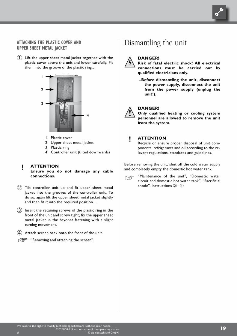
Lift the upper sheet metal jacket together with the plastic cover above the unit and lower carefully, Fit them into the groove of the plastic ring…
1 Plastic cover2 Upper sheet metal jacket3 Plastic ring4 Controller unit (tilted downwards)
ATTENTION Ensure you do not damage any cable
connections.
Tilt controller unit up and fit upper sheet metal jacket into the grooves of the controller unit. To do so, again lift the upper sheet metal jacket slightly and then fit it into the required position…
Insert the retaining screws of the plastic ring in the front of the unit and screw tight, fix the upper sheet metal jacket in the bayonet fastening with a slight turning movement.
Attach screen back onto the front of the unit.
“Removing and attaching the screen”.
20We reserve the right to modify technical specifications without prior notice.
83025000cUK – translation of the operating manu-al © ait-deutschland GmbH
OperationThe unit is delivered from the factory with default settings (= factory settings). It can be started up with no further configuration.
The factory settings are basic settings, which you can adapt to individual preferences and operating requirements, to optimise operation and maximise efficiency.
BWP 307+S - the control unit
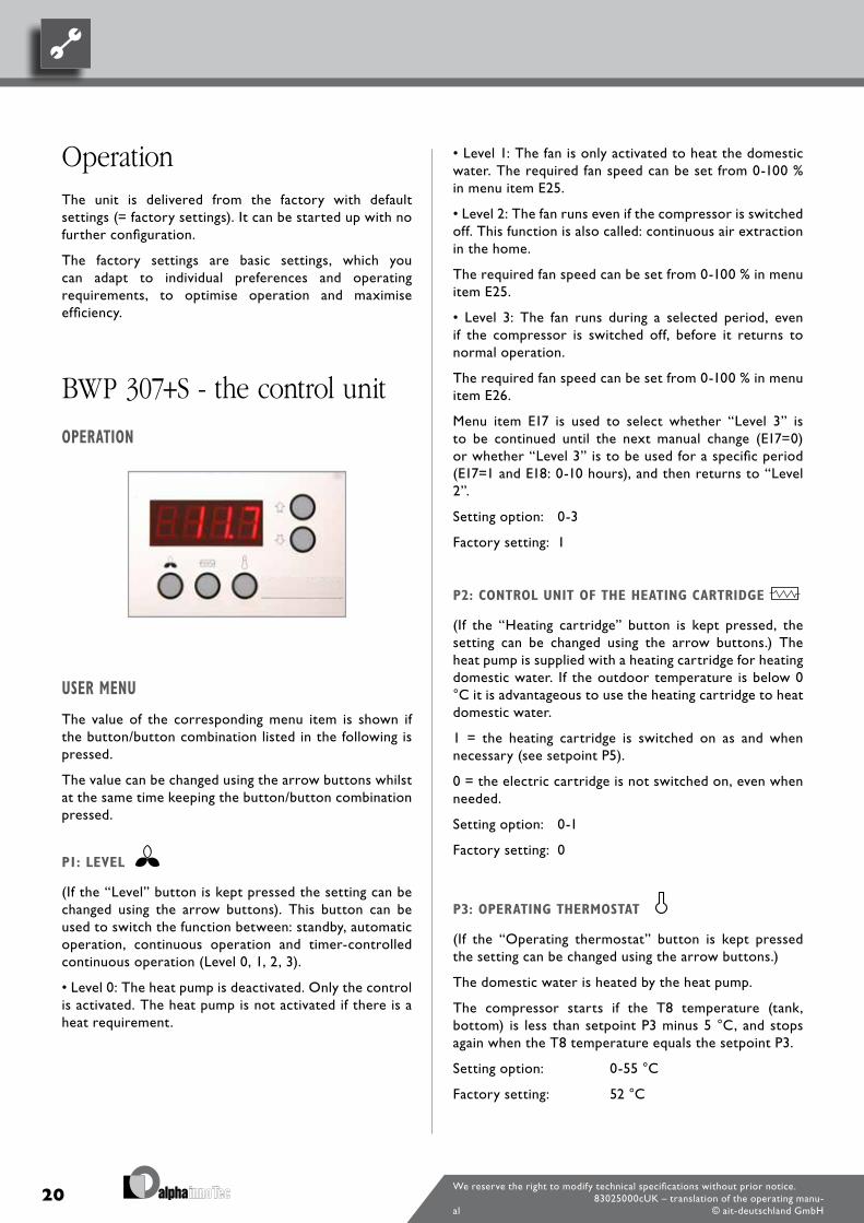
OPERATION
USER MENU
The value of the corresponding menu item is shown if the button/button combination listed in the following is pressed.
The value can be changed using the arrow buttons whilst at the same time keeping the button/button combination pressed.
P1: LEVEL
(If the “Level” button is kept pressed the setting can be changed using the arrow buttons). This button can be used to switch the function between: standby, automatic operation, continuous operation and timer-controlled continuous operation (Level 0, 1, 2, 3).
• Level 0: The heat pump is deactivated. Only the control is activated. The heat pump is not activated if there is a heat requirement.
• Level 1: The fan is only activated to heat the domestic water. The required fan speed can be set from 0-100 % in menu item E25.
• Level 2: The fan runs even if the compressor is switched off. This function is also called: continuous air extraction in the home.
The required fan speed can be set from 0-100 % in menu item E25.
• Level 3: The fan runs during a selected period, even if the compressor is switched off, before it returns to normal operation.
The required fan speed can be set from 0-100 % in menu item E26.
Menu item E17 is used to select whether “Level 3” is to be continued until the next manual change (E17=0) or whether “Level 3” is to be used for a specific period (E17=1 and E18: 0-10 hours), and then returns to “Level 2”.
Setting option: 0-3
Factory setting: 1
P2: CONTROL UNIT OF THE HEATING CARTRIDGE
(If the “Heating cartridge” button is kept pressed, the setting can be changed using the arrow buttons.) The heat pump is supplied with a heating cartridge for heating domestic water. If the outdoor temperature is below 0 °C it is advantageous to use the heating cartridge to heat domestic water.
1 = the heating cartridge is switched on as and when necessary (see setpoint P5).
0 = the electric cartridge is not switched on, even when needed.
Setting option: 0-1
Factory setting: 0
P3: OPERATING THERMOSTAT
(If the “Operating thermostat” button is kept pressed the setting can be changed using the arrow buttons.)
The domestic water is heated by the heat pump.
The compressor starts if the T8 temperature (tank, bottom) is less than setpoint P3 minus 5 °C, and stops again when the T8 temperature equals the setpoint P3.
Setting option: 0-55 °C
Factory setting: 52 °C
21We reserve the right to modify technical specifications without prior notice.
83025000cUK – translation of the operating manu-al © ait-deutschland GmbH
P4: STOP DEFROSTING (BWP 307+S ONLY)
(The “Level” + “Operating thermostat” are both pressed at the same time and are kept pressed down).
The defrosting period usually ends when the chilled surface has reached a temperature of 10 °C. It is sometimes necessary to change this temperature for special operating states.
Setting option: 0-25 °C
Factory setting: 1 0 °C
P5: HEATING CARTRIDGE
(The “Heating cartridge” + “Operating thermostat” are both pressed at the same time and are kept pressed down).
The heating cartridge only heats up the top half of the storage tank, while the heat pump also heats the bottom part of the storage tank. The heating cartridge starts if the T7 temperature (tank, top) falls below the setpoint P5 minus 5°C. It stops when the T7 temperature is above the setpoint P5.
Setting option: 0-65 °C
Factory setting: 50 °C
DISPLAY (MAIN MENU)
Press the arrow buttons to show the various temperatures in the display. Press the arrow buttons until the number from the temperature sensor is displayed. The temperature is displayed after around 3 seconds. The temperature remains displayed for around 30 seconds, before the display switches back to the normal screen. The normal screen display is set using menu item E49 (no display, water temperature T7 or clock).
The following values can be displayed:
T4/T10: Forced operation input (cannot be used for temperature display). In the event of a short circuit the heat pump switches to forced operation.
T5: Upstream of the evaporator
T6: Evaporator
T7: Storage tank, top
T8: Storage tank, bottom
T9: Additional sensor (can be used as a solar collector temperature sensor)
CL: The current time of the installed clock.
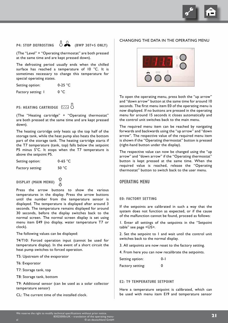
CHANGING THE DATA IN THE OPERATING MENU
To open the operating menu, press both the “up arrow” and “down arrow” button at the same time for around 10 seconds. The first menu item E0 of the operating menu is now displayed. If no buttons are pressed in the operating menu for around 15 seconds it closes automatically and the control unit switches back to the main menu.
The required menu item can be reached by navigating forwards and backwards using the “up arrow” and “down arrow”. The respective value of the required menu item is shown if the “Operating thermostat” button is pressed (right-hand button under the display).
The respective value can now be changed using the “up arrow” and “down arrow” if the “Operating thermostat” button is kept pressed at the same time. When the required value is reached, release the “Operating thermostat” button to switch back to the user menu.
OPERATING MENU
E0: FACTORY SETTING
If the setpoints are calibrated in such a way that the system does not function as expected, or if the cause of the malfunction cannot be found, proceed as follows:
1. Enter all settings of the setpoints in the “Setpoint table” see page <ÜS>.
2. Set the setpoint to 1 and wait until the control unit switches back to the normal display.
3. All setpoints are now reset to the factory setting.
4. From here you can now recalibrate the setpoints.
Setting option: 0-1
Factory setting: 0
E2: T9 TEMPERATURE SETPOINT
Here a temperature setpoint is calibrated, which can be used with menu item E19 and temperature sensor
22We reserve the right to modify technical specifications without prior notice.
83025000cUK – translation of the operating manu-al © ait-deutschland GmbH
T9. It is a separate sensor, which is not included in the standard scope of delivery.
A more detailed description is given under E19.
Setting option: 0-30 °C
Factory setting: 21 °C
E8: DISINFECTION FUNCTION ON/OFF
If the value is set to 1 the water is heated to 65 °C once a week with the help of the heating cartridge, in order to disinfect the storage tank. If the value is set to 0 the disinfection function is deactivated.
Setting option: 0-1
Factory setting: 0
E9: OPERATION IN COLD ENVIRONMENTS
Value 0: If the intake air temperature (T5) is colder than the value set in menu item E10, the compressor is switched off and the heating cartridge is switched on automatically if necessary (P5 and temperature sensor T7). The compressor can be restarted if the intake air temperature (T5) is warmer than the value set in menu item E10 and remains so for 30 minutes.
Value 1: If the intake air temperature (T5) is colder than the value set in menu item E10 the compressor is not switched off, but the heating cartridge is switched on automatically if necessary (P5 and temperature sensor T7).
Setting option: 0-1
Factory setting: 0
E10: OPERATION IN COLD ENVIRONMENTS
Here is where the temperature is set, which determines when the compressor stops and when the heating cartridge is switched on for supplementary heating. See menu item E9.
Setting option: -5 - 10 °C
Factory setting: 0 °C
E13: UNDERFLOOR HEATING TEMPERATURE
Here a temperature setpoint is calibrated, which can be used together with function E19=2. A minimum temperature is set, at which the circulation pump for
the underfloor heating is activated. The circulation pump stops if temperature T8 (storage tank, bottom) falls below the value set in menu item E13.
Setting option: 20-50 °C
Factory setting: 35 °C
E15: HYGROSTAT/STOP SYSTEM
Value 0: The control unit switches to fan speed level 3 if input T10 is short circuited. If T10 is interrupted again the control unit switches back to the level from which it came.
This function can be used by an external hygrostat in order to force the system into level 3 if the humidity is high.
Value 1: The control unit switches to fan speed level 0 (stop system) if input T10 is short circuited. If T10 is interrupted again the control unit switches back to the level from which it came.
Setting option: 0-1
Factory setting: 0
E16: MIN AIR FLOW RATE
This value gives the minimum air flow rate required by the fan during operation. Please note that the cooling system with the outlet at the high-pressure meter can be overloaded if the value calibrated is too high. The value selected should not be higher than necessary, to ensure minimum air flow across the chilled surface.
Setting option: 0-100 %
Factory setting: 0 % (BWP 303+S) 15% (BWP 307+S)
E17: FORCED MODE ON
If P1 is set to level 3 it is possible for the system to be operated automatically at level 2, following the number of hours set in E18.
Value 0 = the system is operated with P1, level 3, until it is set to another level manually.
Value 1 = following the number of hours set in menu item E18 the system is operated at level 2.
Setting option: 0-1
Factory setting: 0
23We reserve the right to modify technical specifications without prior notice.
83025000cUK – translation of the operating manu-al © ait-deutschland GmbH
E18: NUMBER OF HOURS
Setting for the number of hours during which the unit is operated continuously at level 3, before it switches back to level 2 automatically.
This setting is used by function E17=1.
Setting option: 1-10 hours.
Factory setting: 3
E19 : ADDITIONAL FUNCTION (TERMINALS L4 - 1,2)
This function controls relay R9. Solar collector/optional. Value 0: The function is deactivated and the relay is switched off.
Value 1: Solar collector function, which activates the solar pump (R9). The solar pump function is activated if the T8 temperature (tank, bottom) is below the value in menu item E46 (max. tank temperature). The pump is activated if the T9 temperature (solar collector) is above the T8 temperature (tank, bottom) + E20.
The pump stops again if the T9 temperature (solar collector) falls below the T8 temperature (tank, bottom). This function is available regardless of whether the heat pump is running or not.
Value 2: Underfloor heating function, which activates the circulation pump (relay R9). The underfloor heating function is activated if the T8 temperature (tank, bottom) is above the value in menu item E13 (underfloor heating temperature). The pump is activated if the T9 temperature (solar collector) is below the setting in menu item E2. The pump (relay R9) stops again if the T9 temperature (solar collector) is above the setting in menu item E2. This function is available regardless of whether the heat pump is running or not.
Value 3: Solar collector function (RS special function), which activates the solar pump (relay R9). The solar collector function has a higher level safety function, which can deactivate the solar pump.
If the T9 temperature (solar collector) is above 89°C the pump is switched off. The pump is reactivated if the T9 temperature falls below 87 °C.
The solar pump function is activated if the T8 temperature (storage tank, bottom) is lower than the value in menu item E46 (max. storage tank temperature).
The pump is in operation if the T9 temperature (solar collector) is above the T8 temperature (tank, bottom) + menu item E20.
The pump (relay R9) stops again if the T9 temperature (solar collector) falls below the T8 temperature (tank, bottom).
If the pump (relay R9) is activated, the heat pump + the heating cartridge are deactivated.
After pump relay R9 has been deactivated, 15 minutes later the following occurs:
• If the T5 (upstream of the evaporator) temperature is above 5.5°C, the heating pump is activated.
• If the T5 temperature (upstream of the evaporator) is below 4.5° C, the heating cartridge is activated.
Value 4: Cooling function, which activates a 3-way damper, which feeds cold exhaust air into a room with cooling requirement. This function is controlled by the temperature set in menu item E2, and the T9 sensor:
• If the temperature at the T9 sensor is above E2, relay R9 is activated.
• If the temperature at the T9 sensor is below E2, relay R9 is deactivated. This function is available regardless of whether the heat pump is running or not.
Value 5: Cooling function, which activates a 3-way damper, which feeds cold exhaust air into a room with cooling requirement. This function is controlled by the temperature set in menu item E2, and the T9 sensor, however, vice-versa E19=4:
• If the temperature at the T9 sensor is above the value in menu item E2, relay R9 is deactivated.
• If the temperature at the T9 sensor is below the value in menu item E2, relay R9 is activated.
This function is available regardless of whether the heat pump is running or not.
Value 6: relay R9 is activated if the compressor is in operation and is deactivated if it is switched off. This function is available regardless of whether the heat pump is running or not
Setting option: 0-6
Factory setting: 0
E20: SOLAR COLLECTOR HYSTERESIS
Here it is possible to set how long the temperature at the solar collector (T9) should be above the temperature in the storage tank (T8) until the solar pump is activated. See setpoint in menu item E19.
Setting option: 1-5 °C
Factory setting: 5 °C
E21: TX SETPOINT
To avoid too high operating pressure in the cooling system the system output must be reduced during the final time period of the heating phase. The water
24We reserve the right to modify technical specifications without prior notice.
83025000cUK – translation of the operating manu-al © ait-deutschland GmbH
temperature at which the reduction is to begin is set here.
Setting option: 0-55 °C
Factory setting: 45 °C
E23: TMOP
This value gives the highest allowable evaporation temperature. This avoids overloading the cooling system during high ambient temperatures.
Setting option: 0-30 °C
Factory setting: 25 °C
E25: FAN SPEED LEVEL 1 + 2
If extraction from the home is required over a lengthy period, it is possible to switch to level 2 (P1). The fan is now operated continuously until it is switched to another level. The speed at which the fan is to be operated, if level 2 is selected, is set here.
Please note that this setting also limits the maximum speed of the fan.
Setting option: 0-100 %
Factory setting: 100 %
E26: FAN SPEED LEVEL 3
The speed at which the fan is to be operated if level 3 (P1) is selected is set here. This function is selected if forced extraction from the home is required for a specific period.
Please note that this setting also limits the maximum speed of the fan.
Setting option: 0-100 %
Factory setting: 100 %
E45: DTAIR
The minimum air cooling required during heating of the water by the system is set here. The control unit controls the speed of the fan so that the air is only cooled down to the preset temperature. However, the control unit can cool to below the setpoint, if this is necessary for technical reasons. The cooling temperature can be reduced if a higher fan speed is required. Please note that has to be operated fast and with high energy consumption if the temperatures are too low.
Setting option: 1-15 °C
Factory setting: 2 °C (BWP 303+S) 3 °C (BWP 307+S)
E46: MAX. STORAGE TANK TEMPERATURE
To avoid a high temperature in the storage tank when using solar heating or another heating source, the temperature is set to the maximum allowable temperature at the bottom of the storage tank.
This setting is used in menu item E19.
Setting option: 40-70 °CFactory setting: 60 °C
E49: SCREENSAVER (1-3)
The screensaver can be selected here:
1: No display. The sentence flashes to indicate that the system is being supplied with electricity.
2: The water temperature T7 (storage tank, to) is displayed.
3: The time is displayed.
Setting option: 1-3Factory setting: 2
E50: HOURS OF THE INTERNAL CLOCK (0-23)
The hours of the clock can be set here.
E51: MINUTES OF THE INTERNAL CLOCK (0-59)
The minutes of the clock can be set here.
E52: COST-EFFECTIVE PHASE (ON/OFF)
If this option is switched on (ON) (1), the heating cartridge and the heat pump are only operated during the given period with start according to menu item E53 and stop according to menu item E54. If the option is switched off (OFF) (0), the heating cartridge and the heat pump are only operated if necessary or according to the settings.
Setting option: 0-1Factory setting: 0
E53: START TIME OF THE COST-EFFECTIVE PHASE (0-23)
The start time for the cost-effective phase can be set here.
25We reserve the right to modify technical specifications without prior notice.
83025000cUK – translation of the operating manu-al © ait-deutschland GmbH
E54: END TIME OF THE COST-EFFECTIVE PHASE (0-23)
The end time for the cost-effective phase can be set here.
E60: TEMPERATURE DIFFERENCE BETWEEN T5 AND T6
If, after one hour of compressor operation, the T6 temperature (evaporator) is above the T5 temperature (upstream of the evaporator) + the value in menu item E60 the compressor is deactivated. “Er06” then appears on the display.This is a safety function, which indicates that the heat pump is not being operated correctly.The unit must be switched off to reset the error.
Setting option: 0-10 °C
Factory setting: 2 °C
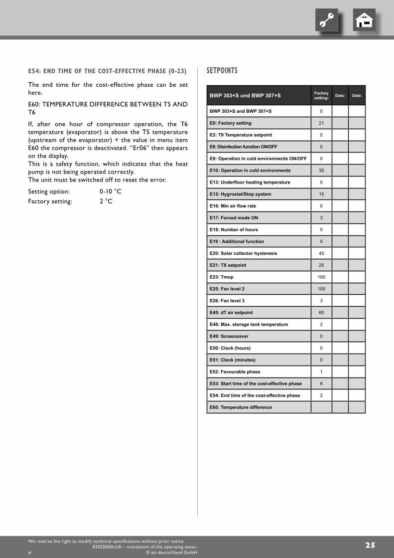
SETPOINTS
BWP 303+S und BWP 307+S Factory setting: Date: Date:
BWP 303+S and BWP 307+S 0
E0: Factory setting 21
E2: T9 Temperature setpoint 0
E8: Disinfection function ON/OFF 0
E9: Operation in cold environments ON/OFF 0
E10: Operation in cold environments 35
E13: Underfloor heating temperature 0
E15: Hygrostat/Stop system 15
E16: Min air flow rate 0
E17: Forced mode ON 3
E18: Number of hours 0
E19 : Additional function 5
E20: Solar collector hysteresis 45
E21: TX setpoint 25
E23: Tmop 100
E25: Fan level 2 100
E26: Fan level 3 3
E45: dT air setpoint 60
E46: Max. storage tank temperature 2
E49: Screensaver 0
E50: Clock (hours) 0
E51: Clock (minutes) 0
E52: Favourable phase 1
E53: Start time of the cost-effective phase 6
E54: End time of the cost-effective phase 2
E60: Temperature difference
26We reserve the right to modify technical specifications without prior notice.
83025000cUK – translation of the operating manu-al © ait-deutschland GmbH
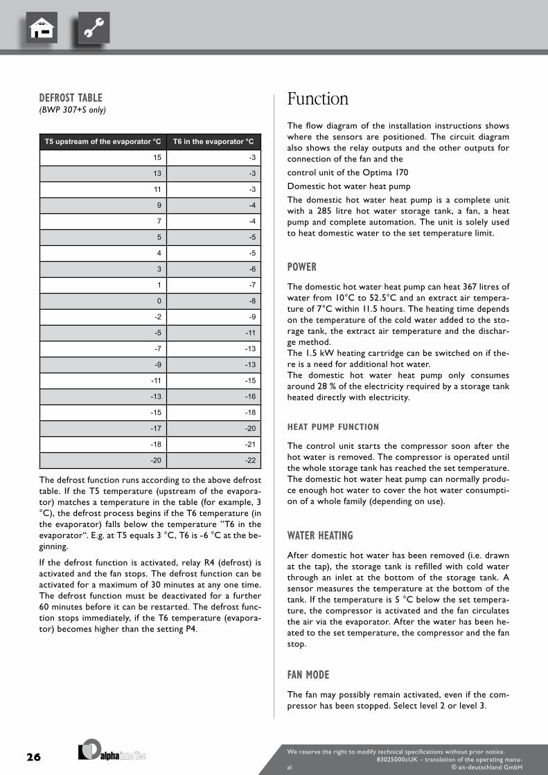
DEFROST TABLE(BWP 307+S only)
T5 upstream of the evaporator °C T6 in the evaporator °C
15 -3
13 -3
11 -3
9 -4
7 -4
5 -5
4 -5
3 -6
1 -7
0 -8
-2 -9
-5 -11
-7 -13
-9 -13
-11 -15
-13 -16
-15 -18
-17 -20
-18 -21
-20 -22
The defrost function runs according to the above defrost table. If the T5 temperature (upstream of the evapora-tor) matches a temperature in the table (for example, 3 °C), the defrost process begins if the T6 temperature (in the evaporator) falls below the temperature ”T6 in the evaporator“. E.g. at T5 equals 3 °C, T6 is -6 °C at the be-ginning.
If the defrost function is activated, relay R4 (defrost) is activated and the fan stops. The defrost function can be activated for a maximum of 30 minutes at any one time. The defrost function must be deactivated for a further 60 minutes before it can be restarted. The defrost func-tion stops immediately, if the T6 temperature (evapora-tor) becomes higher than the setting P4.
FunctionThe flow diagram of the installation instructions shows where the sensors are positioned. The circuit diagram also shows the relay outputs and the other outputs for connection of the fan and the
control unit of the Optima 170
Domestic hot water heat pump
The domestic hot water heat pump is a complete unit with a 285 litre hot water storage tank, a fan, a heat pump and complete automation. The unit is solely used to heat domestic water to the set temperature limit.
POWER
The domestic hot water heat pump can heat 367 litres of water from 10°C to 52.5°C and an extract air tempera-ture of 7°C within 11.5 hours. The heating time depends on the temperature of the cold water added to the sto-rage tank, the extract air temperature and the dischar-ge method.The 1.5 kW heating cartridge can be switched on if the-re is a need for additional hot water.The domestic hot water heat pump only consumes around 28 % of the electricity required by a storage tank heated directly with electricity.
HEAT PUMP FUNCTION
The control unit starts the compressor soon after the hot water is removed. The compressor is operated until the whole storage tank has reached the set temperature. The domestic hot water heat pump can normally produ-ce enough hot water to cover the hot water consumpti-on of a whole family (depending on use).
WATER HEATING
After domestic hot water has been removed (i.e. drawn at the tap), the storage tank is refilled with cold water through an inlet at the bottom of the storage tank. A sensor measures the temperature at the bottom of the tank. If the temperature is 5 °C below the set tempera-ture, the compressor is activated and the fan circulates the air via the evaporator. After the water has been he-ated to the set temperature, the compressor and the fan stop.
FAN MODE
The fan may possibly remain activated, even if the com-pressor has been stopped. Select level 2 or level 3.
27We reserve the right to modify technical specifications without prior notice.
83025000cUK – translation of the operating manu-al © ait-deutschland GmbH
This function is used if a domestic hot water heat pump is used to extract air in the home‘s wet room.
As long as the input to T10 is short circuited the control unit is forced to run at level 3. This state can be used to achieve additional extraction, for example, from the ba-throom, while someone is in the bath. If the input is no longer short circuited the control unit switches back to the level it was at before the short circuit.
DEFROSTING(BWP 307+S only)
If there are ice deposits on the surface of the evaporator the discrepancy between the temperature upstream of the evaporator and in the evaporator becomes too large and the system switches to defrost mode (defrost table, see page <ÜS>). Solenoid valve MA4 is opened, the fan stops until the ice has melted and the evaporator has re-ached a temperature of around 10°C (depending on the setting in menu item P4). The solenoid valve is then clo-sed again and the fan starts.
ADDITIONAL CAPACITY
In the event of a situation occurring in which the do-mestic hot water heat pump is no longer able to supply a sufficient quantity of hot water the integrated heating cartridge can be activated. As a result, twice as much water can be heated. The temperature to which the hea-ting cartridge is to heat the water can be set.
Only use the heating cartridge if necessary. The heating cartridge consumes more energy than the compressor. The heating cartridge is activated manually at the con-trol panel.
OPERATING SAFETY
HIGH-PRESSURE LIMITER
(BWP 307 + S only)
The compressor has a high-pressure limiter which, if the pressure becomes too high, switches off the compressor before it leaves its use tolerance range.
The message „PE“ appears in the display.
If the cause of the error has been found the power sup-ply must be switched off for 10 s in order to reset the high-pressure limiter before the unit can be restarted.
Lower the water temperature by 2-3° C to avoid the high-pressure limiter from being triggered again.
.
SAFETY TEMPERATURE LIMITERS
If an error occurs in the heating cartridge the safety temperature, limiters are deactivated. The button in the middle of the limiters must be pressed to reactivate the safety temperature limiters. The limiters are located on the middle of the storage tank.
ALARM
HIGH-PRESSURE LIMITER ERROR
(BWP 307 + S only)
If the high-pressure limiter is deactivated the message „PE“ appears in the display. The power must be switched off for 10 s and then switched back on again to reacti-vate the limiter. The message „PE“ disappears.
Built-in safety devices
SAFETY TEMPERATURE LIMITERS FOR THE HEATING CARTRIDGE
The safety temperature limiters protect the domestic hot water heat pump against high temperatures that ari-se during heat generation using the heat cartridge. The safety temperature limiters are mounted on the storage tank.The corresponding sensor is mounted on the thermo-well of the heating cartridge.The heating cartridge is deactivated if the set value (80 °C) is exceeded. The heating cartridge cannot be reacti-vated until the temperature has fallen below 80 °C. On renewed activation the power supply to the unit must be deactivated, the front panel dismantled and the front co-ver of the heating cartridge removed. The Reset button can then be pressed.
HINWEIS. Ensure that the cables to the control unit do not
get crushed or pulled out!
Proceed as follows to switch the electric heating element back on again.
28We reserve the right to modify technical specifications without prior notice.
83025000cUK – translation of the operating manu-al © ait-deutschland GmbH
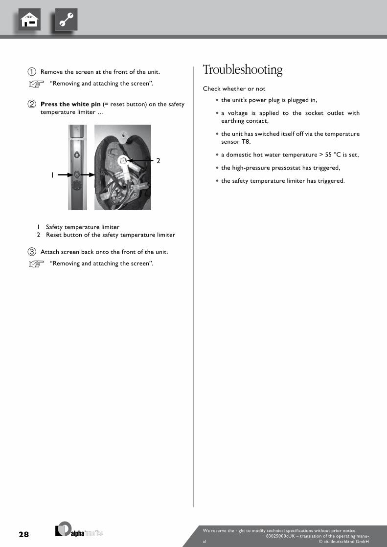
Remove the screen at the front of the unit.
“Removing and attaching the screen”.
Press the white pin (= reset button) on the safety temperature limiter …
1 Safety temperature limiter2 Reset button of the safety temperature limiter
Attach screen back onto the front of the unit.
“Removing and attaching the screen”.
TroubleshootingCheck whether or not
• the unit’s power plug is plugged in,
• a voltage is applied to the socket outlet with earthing contact,
• the unit has switched itself off via the temperature sensor T8,
• a domestic hot water temperature > 55 °C is set,
• the high-pressure pressostat has triggered,
• the safety temperature limiter has triggered.

29We reserve the right to modify technical specifications without prior notice.
83025000cUK – translation of the operating manu-al © ait-deutschland GmbH
30We reserve the right to modify technical specifications without prior notice.
83025000cUK – translation of the operating manu-al © ait-deutschland GmbH
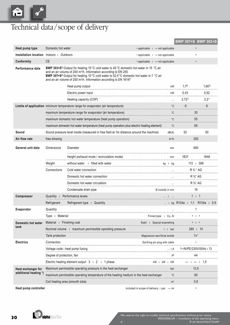
Technical data / scope of delivery
Unit designation BWP 307+S BWP 303+SHeat pump type Domestic hot water • applicable ı — not applicable •
Installation location Indoors ı Outdoors • applicable ı — not applicable •
Conformity CE • applicable ı — not applicable •
Performance data BWP 303+S1):Output for heating 15 °C cold water to 45 °C domestic hot water in 15 °C airand an air volume of 250 m3/h. Information according to EN 255BWP 307+S2):Output for heating 10 °C cold water to 52,5 °C domestic hot water in 7 °C airand an air volume of 250 m3/h. Information according to EN 16147
Heat pump output kW 1,12) 1,661)
Electric power input kW 0,43 0,52
Heating capacity (COP) … 2,722) 3,21)
Limits of application minimum temperature range for evaporator (air temperature) °C -5 8
maximum temperature range for evaporator (air temperature) °C 35
maximum domestic hot water temperature (heat pump operation) °C 55
maximum domestic hot water temperature (heat pump operation plus electric heating element) °C 65
Sound Sound pressure level inside (measured in free field at 1m distance around the machine) dB(A) 52 50
Air flow rate free-blowing m³/h 250
General unit data Dimensions Diameter mm 660
Height (exhaust mode / recirculation mode) mm 1837 1846
Weight without water ı filled with water kg ı kg 113 ı 398
Connections Cold water connection … R ¾ “ AG
Domestic hot water connection … R ¾“ AG
Domestic hot water circulation … R ¾“ AG
Condensate drain pipe Ø outside in mm 19
Compressor Quantity ı Performance levels … ı … 1 ı 1
Refrigerant Refrigerant type ı Quantity … ı kg R134a ı 1,1 R134a ı 0,9
Evaporator Quantity … 1
Type ı Material Finned pipe ı Cu, Al • ı •
Domestic hot water tank
Material ı Finishing coat Stahl ı Special enamelling • ı •
Nominal volume ı maximum permissible operating pressure l ı bar 285 ı 10
Tank protection Magnesium sacrificial anode 1¼“
Electrics Connection Earthing pin plug with cable •
Voltage code ı heat pump fusing … ı A 1~/N/PE/230V/50Hz ı 13
Degree of protection, fan IP 44
Electric heating element output 3 ı 2 ı 1 phase kW ı kW ı kW — ı — ı 1,5
Heat exchanger for additional heating *)
Maximum permissible operating pressure in the heat exchanger bar 13,5
maximum permissible operating temperature of the heating medium in the heat exchanger °C 90
Coil heating area (smooth tube) m2 0,8
Heat pump controller included in scope of delivery: • yes — no •
31We reserve the right to modify technical specifications without prior notice.
83025000cUK – translation of the operating manu-al © ait-deutschland GmbH
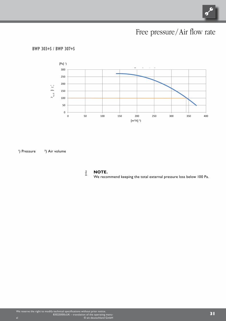
BWP 303+S / BWP 307+S
Free pressure / Air flow rate
1) Pressure 2) Air volume
NOTE. We recommend keeping the total external pressure loss below 100 Pa.
0
50
100
150
200
250
300
0 50 100
Vanvex luftmængde(m
150 200 250 300
Vanvex luftmængde(m3/h)
Luftmængde (m3/h)
300 350 400
[m³/h] 2)
[Pa] 1)
32We reserve the right to modify technical specifications without prior notice.
83025000cUK – translation of the operating manu-al © ait-deutschland GmbH
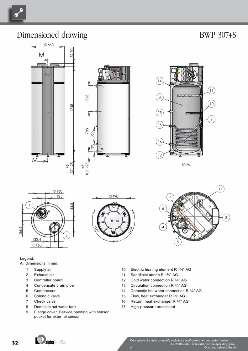
Dimensioned drawing BWP 307+S
Legend:All dimensions in mm.
1 Supply air 10 Electric heating element R 1½" AG2 Exhaust air 11 Sacrificial anode R 1¼" AG3 Controller board 12 Cold water connection R 3 ⁄4" AG4 Condensate drain pipe 13 Circulation connection R 3 ⁄4“ AG5 Compressor 14 Domestic hot water connection R 3 ⁄4" AG6 Solenoid valve 15 Flow, heat exchanger R 3 ⁄4" AG7 Check valve 16 Return, heat exchanger R 3 ⁄4" AG8 Domestic hot water tank 17 High-pressure pressostat9 Flange cover / Service opening with sensor
pocket for external sensor
660
52,5
017
4837
-25
+ 5
M
M
125
132,4
144,
5
136,
4
160
160
1
2
788
513
105
-25
+5
139
365
3
4
5
6
7
120°
120°
490
M-M
8
9
10
11
12
13
14
15
16
17
33
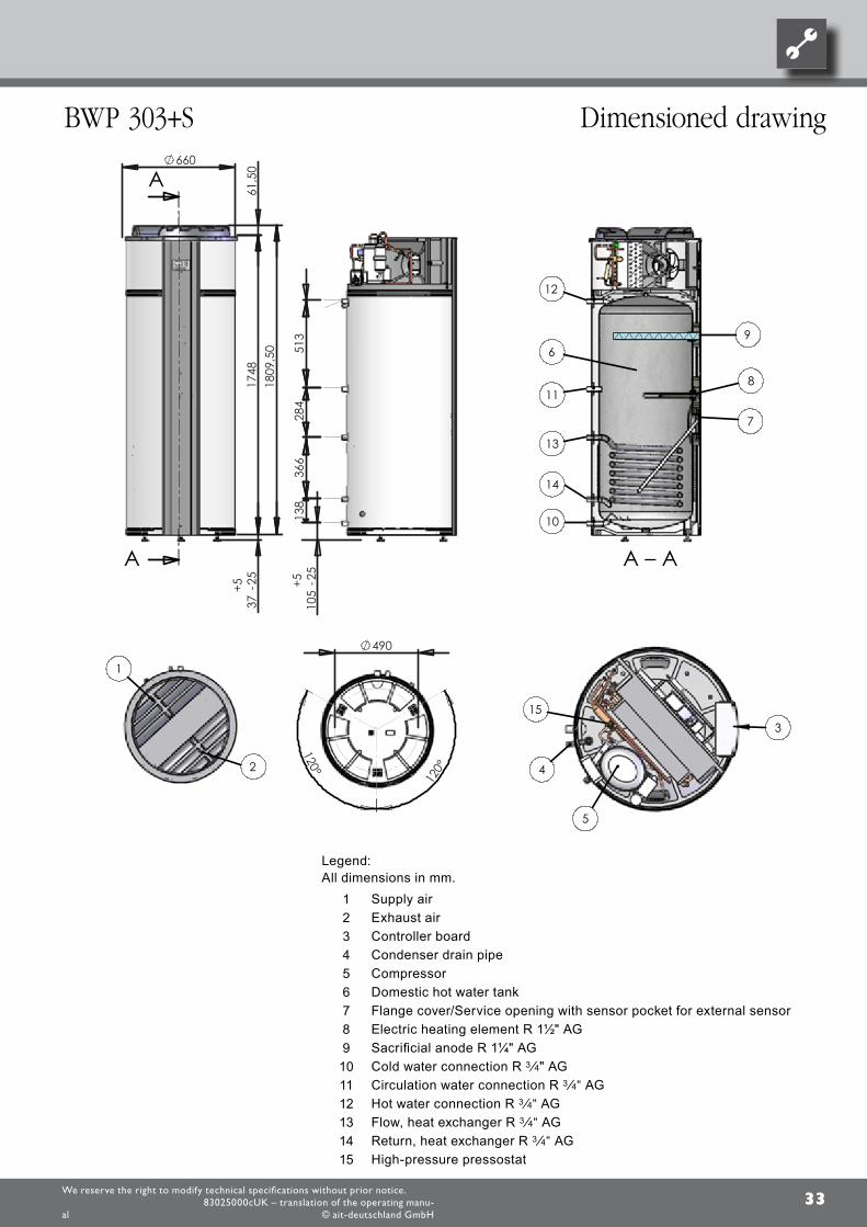
Legend:All dimensions in mm.
1 Supply air 2 Exhaust air3 Controller board4 Condenser drain pipe 5 Compressor6 Domestic hot water tank7 Flange cover/Service opening with sensor pocket for external sensor8 Electric heating element R 1½" AG9 Sacrificial anode R 1¼" AG10 Cold water connection R 3 ⁄4" AG11 Circulation water connection R 3 ⁄4“ AG12 Hot water connection R 3 ⁄4“ AG13 Flow, heat exchanger R 3 ⁄4“ AG14 Return, heat exchanger R 3 ⁄4“ AG15 High-pressure pressostat
We reserve the right to modify technical specifications without prior notice.83025000cUK – translation of the operating manu-
al © ait-deutschland GmbH
BWP 303+S Dimensioned drawing
120°
120°
490
660
37-2
5+5
1748
61,5
0
A
A
105
-25
+536
613
851
328
4
6
8
7
12
11
10
1
2
3
4
5
13
14
1809
,50
9
15
A – A
34We reserve the right to modify technical specifications without prior notice.
83025000cUK – translation of the operating manu-al © ait-deutschland GmbH
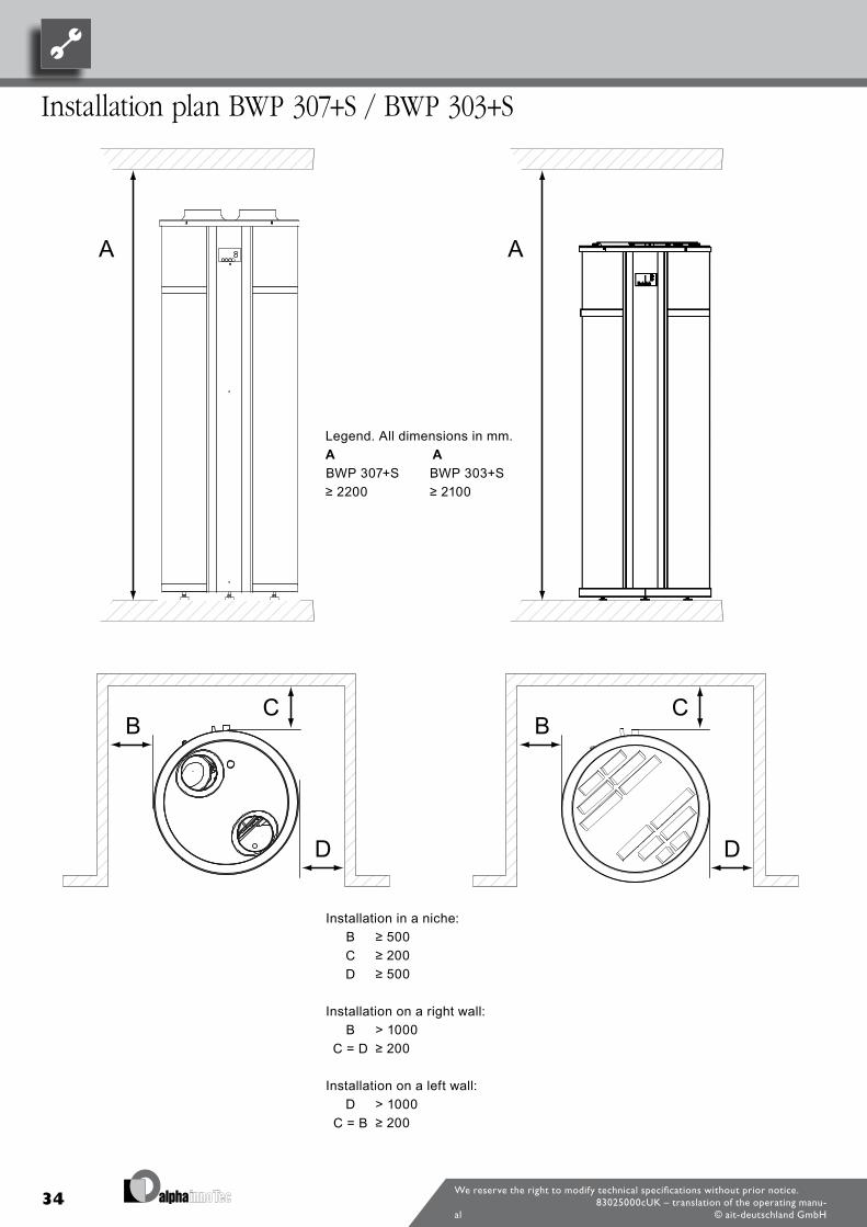
Installation plan BWP 307+S / BWP 303+S
Legend. All dimensions in mm.A ABWP 307+S BWP 303+S≥ 2200 ≥ 2100
Installation in a niche:B ≥ 500C ≥ 200D ≥ 500
Installation on a right wall:B > 1000
C = D ≥ 200
Installation on a left wall:D > 1000
C = B ≥ 200
35We reserve the right to modify technical specifications without prior notice.
83025000cUK – translation of the operating manu-al © ait-deutschland GmbH
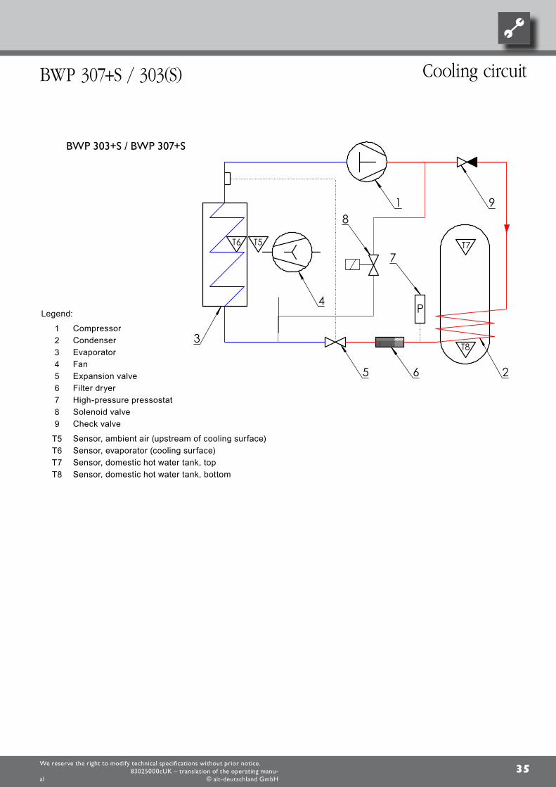
Cooling circuitBWP 307+S / 303(S)
Legend:
1 Compressor2 Condenser3 Evaporator4 Fan5 Expansion valve6 Filter dryer7 High-pressure pressostat8 Solenoid valve9 Check valve
T5 Sensor, ambient air (upstream of cooling surface)T6 Sensor, evaporator (cooling surface)T7 Sensor, domestic hot water tank, topT8 Sensor, domestic hot water tank, bottom
BWP 303+S / BWP 307+S
1
7
65
3
P
2
4
T6 T5 T7
T8
T5, T6, T7, T8 - følere/sensors/Fühler
89
36We reserve the right to modify technical specifications without prior notice.
83025000cUK – translation of the operating manu-al © ait-deutschland GmbH
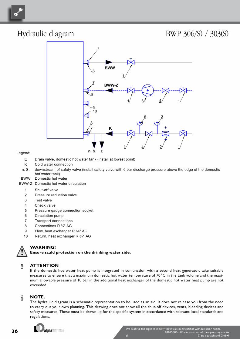
Hydraulic diagram BWP 306/S) / 303(S)
Legend:
E Drain valve, domestic hot water tank (install at lowest point)K Cold water connection
n. S. downstream of safety valve (install safety valve with 6 bar discharge pressure above the edge of the domestic hot water tank)
BWW Domestic hot waterBWW-Z Domestic hot water circulation
1 Shut-off valve2 Pressure reduction valve3 Test valve4 Check valve5 Pressure gauge connection socket6 Circulation pump7 Transport connections8 Connections R ¾" AG9 Flow, heat exchanger R 3 ⁄4" AG10 Return, heat exchanger R 3 ⁄4" AG
WARNING! Ensure scald protection on the drinking water side.
ATTENTION If the domestic hot water heat pump is integrated in conjunction with a second heat generator, take suitable
measures to ensure that a maximum domestic hot water temperature of 70 °C in the tank volume and the maxi-mum allowable pressure of 10 bar in the additional heat exchanger of the domestic hot water heat pump are not exceeded.
NOTE. The hydraulic diagram is a schematic representation to be used as an aid. It does not release you from the need
to carry out your own planning. This drawing does not show all the shut-off devices, vents, bleeding devices and safety measures. These must be drawn up for the specific system in accordance with relevant local standards and regulations.
1 4 16
21 14
5 3
18
8
8
7
7
7
910
BWW
BWW-Z
K
En. S.
37
T
M
T
108
30
6
45
R9
T8
T9
We reserve the right to modify technical specifications without prior notice.83025000cUK – translation of the operating manu-
al © ait-deutschland GmbH
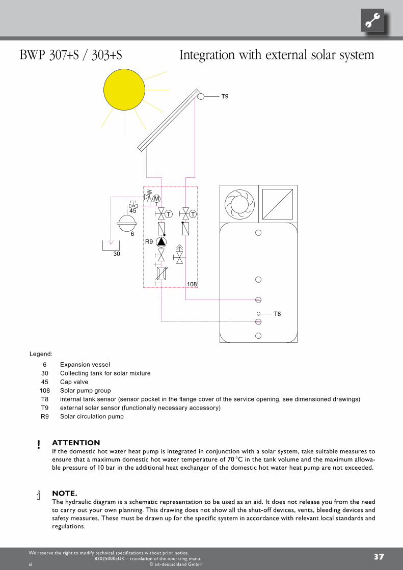
BWP 307+S / 303+S Integration with external solar system
Legend:
6 Expansion vessel30 Collecting tank for solar mixture45 Cap valve
108 Solar pump groupT8 internal tank sensor (sensor pocket in the flange cover of the service opening, see dimensioned drawings)T9 external solar sensor (functionally necessary accessory)R9 Solar circulation pump
ATTENTION If the domestic hot water heat pump is integrated in conjunction with a solar system, take suitable measures to
ensure that a maximum domestic hot water temperature of 70 °C in the tank volume and the maximum allowa-ble pressure of 10 bar in the additional heat exchanger of the domestic hot water heat pump are not exceeded.
NOTE. The hydraulic diagram is a schematic representation to be used as an aid. It does not release you from the need
to carry out your own planning. This drawing does not show all the shut-off devices, vents, bleeding devices and safety measures. These must be drawn up for the specific system in accordance with relevant local standards and regulations.
38
101 *)
211
8
8
10
8
D
724
16
52
8 10 8
8
101
101
101
We reserve the right to modify technical specifications without prior notice.83025000cUK – translation of the operating manu-
al © ait-deutschland GmbH
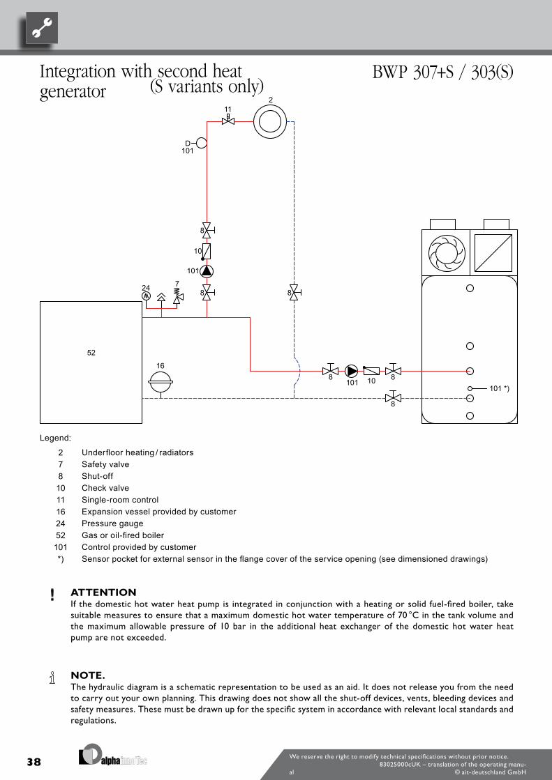
Integration with second heat generator
BWP 307+S / 303(S)
Legend:
2 Underfloor heating / radiators7 Safety valve8 Shut-off10 Check valve11 Single-room control16 Expansion vessel provided by customer24 Pressure gauge52 Gas or oil-fired boiler101 Control provided by customer*) Sensor pocket for external sensor in the flange cover of the service opening (see dimensioned drawings)
ATTENTION If the domestic hot water heat pump is integrated in conjunction with a heating or solid fuel-fired boiler, take
suitable measures to ensure that a maximum domestic hot water temperature of 70 °C in the tank volume and the maximum allowable pressure of 10 bar in the additional heat exchanger of the domestic hot water heat pump are not exceeded.
NOTE. The hydraulic diagram is a schematic representation to be used as an aid. It does not release you from the need
to carry out your own planning. This drawing does not show all the shut-off devices, vents, bleeding devices and safety measures. These must be drawn up for the specific system in accordance with relevant local standards and regulations.
(S variants only)

39We reserve the right to modify technical specifications without prior notice.
83025000cUK – translation of the operating manu-al © ait-deutschland GmbH
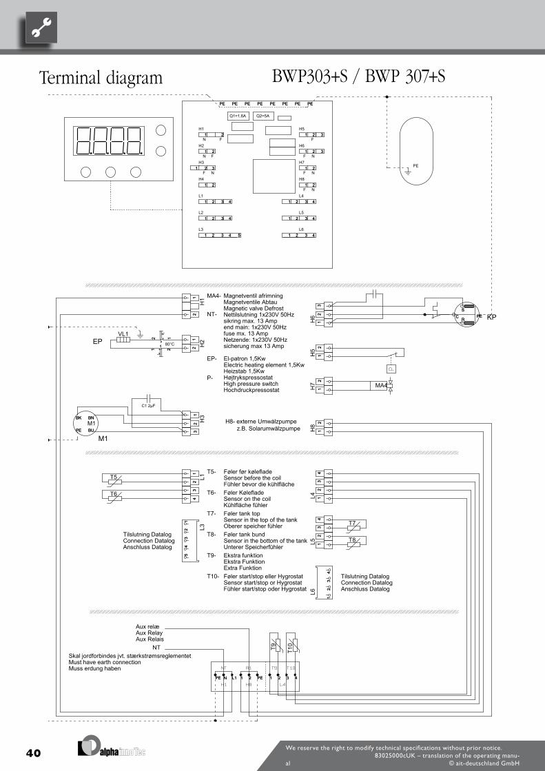
40We reserve the right to modify technical specifications without prior notice.
83025000cUK – translation of the operating manu-al © ait-deutschland GmbH
Terminal diagram BWP303+S / BWP 307+S
EP
M1
KP
NT
Aux relæAux RelayAux Relais
El-patron 1,5KwElectric heating element 1,5KwHeizstab 1,5KwHøjtrykspressostatHigh pressure switchHochdruckpressostat
Magnetventil afrimningMagnetventile AbtauMagnetic valve DefrostNettilslutning 1x230V 50Hz sikring max. 13 Ampend main: 1x230V 50Hz fuse mx. 13 AmpNetzende: 1x230V 50Hz sicherung max 13 Amp
Skal jordforbindes jvt. stærkstrømsreglementetMust have earth connectionMuss erdung haben
Tilslutning DatalogConnection DatalogAnschluss Datalog
Tilslutning DatalogConnection DatalogAnschluss Datalog
MA4-
NT-
EP-
P-
T5-
T6-
T7-
T8-
T9-
T10-
80°C
Føler før kølefladeSensor before the coilFühler bevor die kühlflächeFøler KølefladeSensor on the coilKühlfläche fühlerFøler tank topSensor in the top of the tankOberer speicher fühlerFøler tank bundSensor in the bottom of the tankUnterer SpeicherfühlerEkstra funktionEkstra FunktionExtra FunktionFøler start/stop eller HygrostatSensor start/stop or HygrostatFühler start/stop oder Hygrostat
12
12
H1
12
12 H
2
12
12
H5
12
12
H7
12
12
H8
12
34
12
34
L1
12
34
12
34
L41
23
41
23
4L5
12
31
23
H3
12
31
23
H6
12
34
51
23
45
L3
12
34
12
34
L6
11 22 3 4L1N PEPE 11 22 3 4L1N PEPE
T5
T6
T7
T8
VL1
MA4
C1 2µF
BU
BNBK
PE BU
BNBK
PEM1
C PER
SC PE
R
S
T9 T10
PE12 12
1 21 2
1
1
1
1
1
1 1
1
1
1
1
1
11
2 2
2
2
2
2
2
2
2
2
2
2
2 2
3
3
3
3
3
3
3
3
3
4
4
4
4
4
4
5
EPEPPE PEPE PEPE PE
Q1=1,6A Q2=5A
H1
H2
H3
H4
H5
H6
H7
H8
L1
L2
L4
L5
L3 L6
F
F
F
F
F
F
F
N
N
N
N
N
N1
1
1
1
1
1 1
1
1
1
1
1
11
2 2
2
2
2
2
2
2
2
2
2
2
2 2
3
3
3
3
3
3
3
3
3
4
4
4
4
4
4
5
EPEPPE PEPE PEPE PE
H8- externe Umwälzpumpe z.B. Solarumwälzpumpe
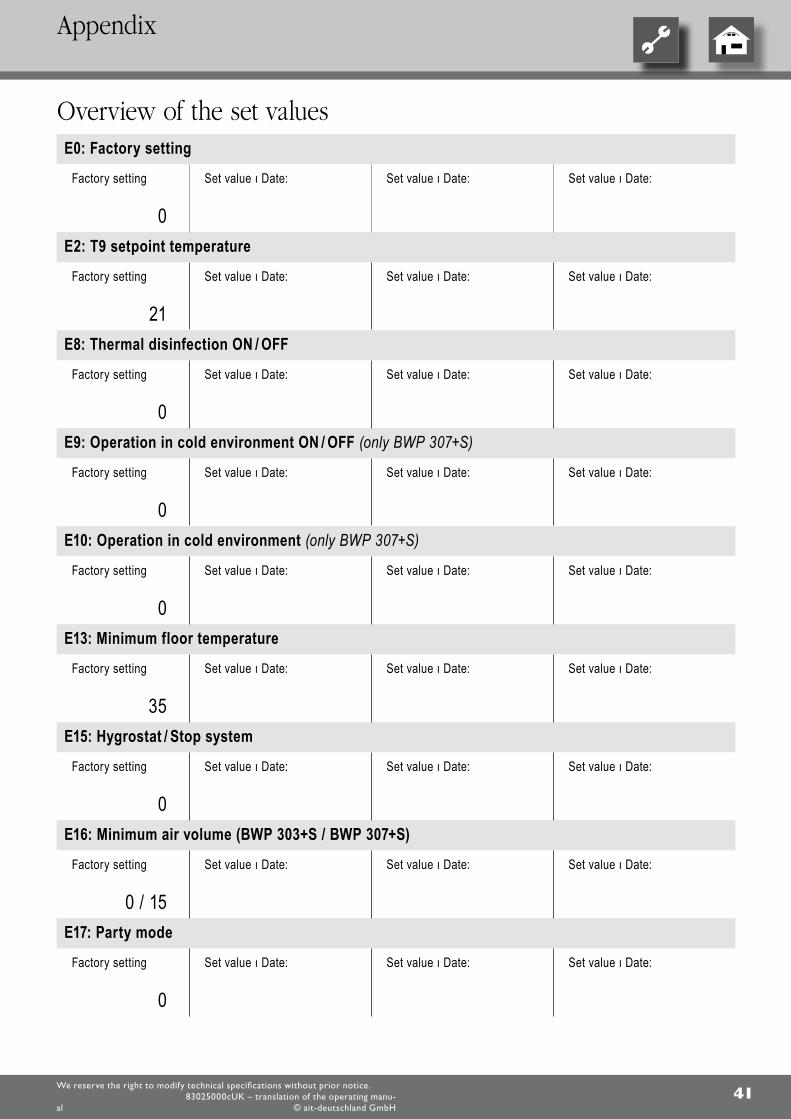
41We reserve the right to modify technical specifications without prior notice.
83025000cUK – translation of the operating manu-al © ait-deutschland GmbH
Overview of the set valuesE0: Factory setting
Factory setting
0
Set value ı Date: Set value ı Date: Set value ı Date:
E2: T9 setpoint temperature
Factory setting
21
Set value ı Date: Set value ı Date: Set value ı Date:
E8: Thermal disinfection ON / OFF
Factory setting
0
Set value ı Date: Set value ı Date: Set value ı Date:
E9: Operation in cold environment ON / OFF (only BWP 307+S)
Factory setting
0
Set value ı Date: Set value ı Date: Set value ı Date:
E10: Operation in cold environment (only BWP 307+S)
Factory setting
0
Set value ı Date: Set value ı Date: Set value ı Date:
E13: Minimum floor temperature
Factory setting
35
Set value ı Date: Set value ı Date: Set value ı Date:
E15: Hygrostat / Stop system
Factory setting
0
Set value ı Date: Set value ı Date: Set value ı Date:
E16: Minimum air volume (BWP 303+S / BWP 307+S)
Factory setting
0 / 15
Set value ı Date: Set value ı Date: Set value ı Date:
E17: Party mode
Factory setting
0
Set value ı Date: Set value ı Date: Set value ı Date:
Appendix
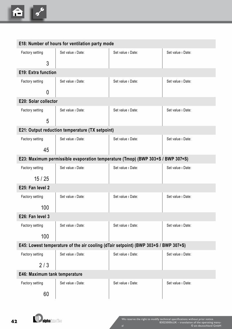
42We reserve the right to modify technical specifications without prior notice.
83025000cUK – translation of the operating manu-al © ait-deutschland GmbH
E18: Number of hours for ventilation party mode
Factory setting
3
Set value ı Date: Set value ı Date: Set value ı Date:
E19: Extra function
Factory setting
0
Set value ı Date: Set value ı Date: Set value ı Date:
E20: Solar collector
Factory setting
5
Set value ı Date: Set value ı Date: Set value ı Date:
E21: Output reduction temperature (TX setpoint)
Factory setting
45
Set value ı Date: Set value ı Date: Set value ı Date:
E23: Maximum permissible evaporation temperature (Tmop) (BWP 303+S / BWP 307+S)
Factory setting
15 / 25
Set value ı Date: Set value ı Date: Set value ı Date:
E25: Fan level 2
Factory setting
100
Set value ı Date: Set value ı Date: Set value ı Date:
E26: Fan level 3
Factory setting
100
Set value ı Date: Set value ı Date: Set value ı Date:
E45: Lowest temperature of the air cooling (dTair setpoint) (BWP 303+S / BWP 307+S)
Factory setting
2 / 3
Set value ı Date: Set value ı Date: Set value ı Date:
E46: Maximum tank temperature
Factory setting
60
Set value ı Date: Set value ı Date: Set value ı Date:
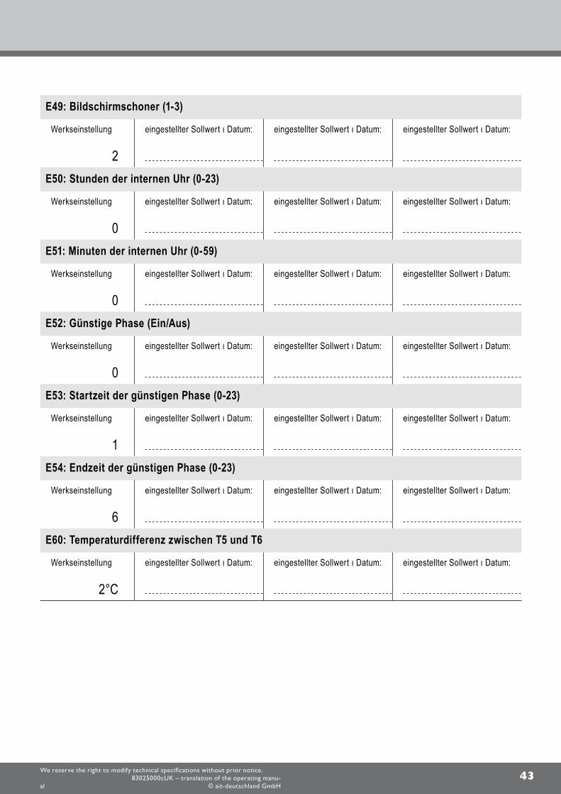
43We reserve the right to modify technical specifications without prior notice.
83025000cUK – translation of the operating manu-al © ait-deutschland GmbH
E49: Bildschirmschoner (1-3)
Werkseinstellung
2
eingestellter Sollwert ı Datum: eingestellter Sollwert ı Datum: eingestellter Sollwert ı Datum:
E50: Stunden der internen Uhr (0-23)
Werkseinstellung
0
eingestellter Sollwert ı Datum: eingestellter Sollwert ı Datum: eingestellter Sollwert ı Datum:
E51: Minuten der internen Uhr (0-59)
Werkseinstellung
0
eingestellter Sollwert ı Datum: eingestellter Sollwert ı Datum: eingestellter Sollwert ı Datum:
E52: Günstige Phase (Ein/Aus)
Werkseinstellung
0
eingestellter Sollwert ı Datum: eingestellter Sollwert ı Datum: eingestellter Sollwert ı Datum:
E53: Startzeit der günstigen Phase (0-23)
Werkseinstellung
1
eingestellter Sollwert ı Datum: eingestellter Sollwert ı Datum: eingestellter Sollwert ı Datum:
E54: Endzeit der günstigen Phase (0-23)
Werkseinstellung
6
eingestellter Sollwert ı Datum: eingestellter Sollwert ı Datum: eingestellter Sollwert ı Datum:
E60: Temperaturdifferenz zwischen T5 und T6
Werkseinstellung
2°C
eingestellter Sollwert ı Datum: eingestellter Sollwert ı Datum: eingestellter Sollwert ı Datum:
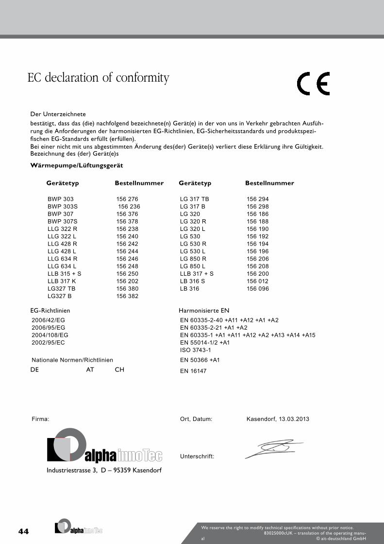
44We reserve the right to modify technical specifications without prior notice.
83025000cUK – translation of the operating manu-al © ait-deutschland GmbH
EC declaration of conformity
Der Unterzeichnetebestätigt, dass das (die) nachfolgend bezeichnete(n) Gerät(e) in der von uns in Verkehr gebrachten Ausfüh-rung die Anforderungen der harmonisierten EG-Richtlinien, EG-Sicherheitsstandards und produktspezi-fischen EG-Standards erfüllt (erfüllen). Bei einer nicht mit uns abgestimmten Änderung des(der) Geräte(s) verliert diese Erklärung ihre Gültigkeit.Bezeichnung des (der) Gerät(e)s
Wärmepumpe/Lüftungsgerät
Gerätetyp Bestellnummer Gerätetyp Bestellnummer
BWP 303 156 276 LG 317 TB 156 294BWP 303S 156 236 LG 317 B 156 298BWP 307 156 376 LG 320 156 186BWP 307S 156 378 LG 320 R 156 188LLG 322 R 156 238 LG 320 L 156 190LLG 322 L 156 240 LG 530 156 192LLG 428 R 156 242 LG 530 R 156 194LLG 428 L 156 244 LG 530 L 156 196LLG 634 R 156 246 LG 850 R 156 206LLG 634 L 156 248 LG 850 L 156 208LLB 315 + S 156 250 LLB 317 + S 156 200LLB 317 K 156 202 LB 316 S 156 012LG327 TB 156 380 LB 316 156 096LG327 B 156 382
EG-Richtlinien Harmonisierte EN
2006/42/EG EN 60335-2-40 +A11 +A12 +A1 +A22006/95/EG EN 60335-2-21 +A1 +A22004/108/EG EN 60335-1 +A1 +A11 +A12 +A2 +A13 +A14 +A152002/95/EC EN 55014-1/2 +A1
ISO 3743-1
Nationale Normen/Richtlinien EN 50366 +A1
DE AT CH EN 16147
Firma: Ort, Datum: Kasendorf, 13.03.2013
Unterschrift:

45We reserve the right to modify technical specifications without prior notice.
83025000cUK – translation of the operating manu-al © ait-deutschland GmbH
Space for notes

46 We reserve the right to modify technical specifications without prior notice.83025000cUK – translation of the operating manu-
al © ait-deutschland GmbH

47We reserve the right to modify technical specifications without prior notice.83025000cUK – translation of the operating manu-
al © ait-deutschland GmbH


![The theory of the Hampson Liquefier · 2012-10-03 · Buckingham.] TheTkeovyoftheHampsonLiquefier. 127 asslightchangesinthedistributionoftemperatureinsidethe liquefiermayinfluencethethermalleakageinfromoutside.If](https://img.pdfslide.us/doc/110x75/5e910f759c06a047796d0b21/the-theory-of-the-hampson-liquefier-2012-10-03-buckingham-thetkeovyofthehampsonliquefier.jpg)