Embed Size (px)
Citation preview

ARENBERG DOCTORAL SCHOOLFaculty of Engineering
Domain Specific Languagesfor Hard Real-Time SafeCoordination of Robot andMachine Tool Systems
Markus Klotzbücher
Dissertation presented in partialfulfillment of the requirements for thethe degree of Doctor in Engineering
April 2013

Domain Specific Languages for Hard Real-Time SafeCoordination of Robot and Machine Tool Systems
Markus KLOTZBÜCHER
Jury:Prof. dr. ir. P. Verbaeten, chairProf. dr. ir. H. Bruyninckx, supervisorProf. dr. ir. Y. Berbersdr. S. Michielsdr. ir. M. Engels(FMTC)
dr. ir. F. Ingrand(LAAS/CNRS Toulouse)
dr. ir. M. J. G. van de Molengraft(Technische Universiteit Eindhoven)
Dissertation presented in partialfulfillment of the requirements forthe degree of Doctorin Engineering
April 2013
© KU Leuven – Faculty of EngineeringCelestijnenlaan 300B box 2420, B-3001 Heverlee (Belgium)
Alle rechten voorbehouden. Niets uit deze uitgave mag worden vermenigvuldigden/of openbaar gemaakt worden door middel van druk, fotocopie, microfilm,elektronisch of op welke andere wijze ook zonder voorafgaande schriftelijketoestemming van de uitgever.
All rights reserved. No part of the publication may be reproduced in any formby print, photoprint, microfilm or any other means without written permissionfrom the publisher.
D/2013/7515/31ISBN 978-94-6018-645-5

Preface
In 2007 I was becoming increasingly uneasy. This was, strangely enough, dueto my professional life going decidedly well. My job as a freelance consultantwas running smoothly, I was regularly teaching industrial seminars and hadin general reached a level of confidence necessary to make consulting fun. Mydiscomfort resulted from my long standing wish to pursue a PhD, to acquiredeeper knowledge of Robotics and Automation and to have the chance to spenda significant amount of time focusing on one topic. I knew that if I didn’t startsoon, it was not going to happen anymore.
Moreover, the number of possibilities was further reduced by the self-imposedconstraint of wanting to work with Free and Open Source Software. All thehappier I was when Carsten Emde from OSADL pointed me in the directionof Herman Bruyninckx of the robotics group at KU Leuven. After exchanginga couple of emails and a first visit to Leuven, I was soon convinced to havefound the perfect place: a group of friendly and knowledgeable people, deepinvolvement in Open Source through the OROCOS project, industrial robotsand a Professor who replied to email inline and in plain text. . .
This work would not have been possible without the help of many. Firstly, Iwant to thank Herman for accepting me without hesitation as a latecomer andfor patiently helping me getting into the domain of robotics and control. I verymuch appreciated your motivating, yet critical coaching style and your effortsto literally almost always be available to discuss ideas, while at the same timeoffering the freedom to work independently. I’ve also grown fond of eating icecream for supper.
I would like to thank the members of my assessor committee and jury YolandeBerbers, René van de Molengraft and Marc Engels for continuously providingvaluable feedback to my research. Together with the other members of my jury,Félix Ingrand and Sam Michiels, your comments have much improved my thesis.Thank you Prof. Verbaeten for chairing my defence.
i

ii PREFACE
I also much appreciate the help of Joris de Schutter, who, though less directlyinvolved in my research, has repeatedly provided valuable suggestions andfeedback.
I am very grateful to Carsten Emde for pointing me in the right direction atthe right time.
I want to thank my former colleagues Wolfgang Denk and Detlev Zundel, whosupported my endeavor by helping me during the first hybrid working–pre-doctoral year. Thank you Detlev for getting me into functional programming,it has profoundly influenced the way I develop software.
I would also like to acknowledge the members of the BRICS project, in particularthose part of the Component Model Task Force, for the countless fierce butconstructive discussions, which have certainly influenced this work.
Thank you European taxpayers for funding my research through the BRICSand Rosetta European FP7 research projects.
I would also like to acknowledge the Orocos community for the numerous, longmailing list discussions, for testing and adopting my software and for providingfeedback that has helped to strengthen this work.
Thank you Tinne for having helped with almost everything which was importantto me throughout the last years: starting from questions on kinematics andcontrol theory over PhD school organizational issues to the topic of “kids andbabies in Belgium”. I also very much appreciate you translating my abstract toDutch on very short notice!
Thank you Peter Soetens for the friendly welcome in Leuven, for generouslysharing your experience as a former PhD student and for supporting my plansto overhaul RTT’s scripting and state machines. Thank you Klaas for providingindustrial relevant use-cases and Ruben for having helped a lot to improve myunderstanding of motion control and of course for the enjoyable hours of fightingwith early versions of the YouBot. Thank you Wilm for helping with questionson control and of course for our enjoyable road-trip to Yosemite National Parktogether with Nick.
I would also like to thank my fellow PhD students: Enrico for taking carethat the caffeine flow is not interrupted, Hans and Koen for helping me toget Ernie and Bert back to life, Steven for the help with Observers, Nick,Niccoló and Enea for early testing and adopting my software, Lin for showingand explaining his newest gadgets, Azamat for the interesting discussions onfunctional composition and Bart for proofreading my Dutch abstract.
PREFACE iii
I am very grateful to Omi Brigitta for all her help and for coming to Leuvencountless times to help out when I was traveling.
I want to sincerely thank my parents Kurt and Angela Klotzbücher for theirtireless support and encouragement, and the many visits to help with the kids.Thank you Dad for inspiring me to become an engineer.
Dorothee, thank you so much for supporting me from the start, for having thecourage to start a family abroad and for taking such good care of our wonderfulkids. Thank you Yara and Lukas for reminding your Dad each day of whatreally matters.
Markus Klotzbücher,Leuven, March 2013.

Abstract
The software controlling modern robotic and machine tool systems is becomingincreasingly complex. This has several reasons: distributed system architecturesinvolving autonomous, loosely connected subsystems are becoming more andmore prevalent and are replacing simpler, centralized ones. At the same time, theneed to keep software development costs low mandates reuse and integration ofexisting subsystems, which further contributes to complexity due to the need foradditional harmonization and adaptation layers. The increasing universality ofmodern lightweight robots and mobile platforms is also reflected on the software,which must cope with stronger demands in terms of variability, composabilityand reconfigurability.
One approach to deal with this complexity is the Model Based Engineering(MBE) paradigm, which has already been successfully applied to domains suchas automotive, aerospace and control engineering. In this approach the focusis shifted from traditional programming to capturing the required informationin models. These models can subsequently be transformed to executable form,but without having to assume beforehand how this will be done. Moreover,these models can remain available at runtime to permit online adaptation bythe robot itself. This thesis explores the applicability of MBE to the domain ofdistributed, real-time robotic and machine tools systems with a focus on thecoordination of the discrete behavior of such systems.
Coordination is a system level concern that governs how and when functionalsubsystems interact. By explicitly modeling coordination, the desired behaviorof a system is formalized while permitting functional computations to remainfree of application logic and hence more reusable. More concretely, an approachof modeling using domain specific languages (DSL) is chosen. In this approach,dedicated and composable languages are constructed to model a well confineddomain. In contrast to rich, general purpose modeling languages, this approachyields minimal models that capture the essence of the problem while avoidingthe overhead of generality.
v
vi ABSTRACT
The main contribution of this thesis is the development of a composable DSLnamed rFSM for modeling coordination in distributed and real-time constrainedrobotics and machine tool systems, and an associated approach of applying thismodel. The advantages of providing a minimal, but extensible and composablemodel are demonstrated. Further contributions support, make use of or extendthis contribution. Supporting work demonstrates how DSL models can beinstantaneously executed in hard real-time, and introduces the uMF DSL formodeling structural constraints on DSL models themselves. The applicabilityand potential for improving reuse is shown in experiments using a hybridforce-velocity task specification language together within an rFSM model todefine an assembly task. The work on the Coordination–Configurator patternformalizes a frequently recurring architectural pattern that allows to increasethe performance and reusability of coordination.

Beknopte samenvatting
De controlesoftware voor hedendaagse robotica- en machinesystemen wordtsteeds complexer. Dit heeft verschillende redenen: gedistribueerde systeemar-chitecturen met autonome, losjes met elkaar verbonden subsystemen komensteeds meer voor en vervangen eenvoudigere en gecentraliseerde systemen. Omde softwareontwikkelingskosten laag te houden is er tegelijkertijd nood aanhet hergebruiken en het integreren van bestaande subsystemen. Dit op zijnbeurt draagt bij tot een verhoging van de complexiteit door de nood aanextra harmonisatie- en aanpassingslagen. De software weerspiegelt eveneensde toegenomen universaliteit van moderne lichtgewicht robots en mobieleplatformen die moeten omgaan met de toegenomen vraag naar variabiliteit,samenstelbaarheid en herconfigureerbaarheid.
Eén manier om met deze complexiteit om te gaan is gebaseerd op het Model-Based Engineering (MBE) paradigma dat al succesvol is toegepast in domeinenzoals de automobieltechnologie, luchtvaart encontroleontwerp. Deze benaderingverplaatst de aandacht van het traditioneel programmeren naar het vastleggenvan de vereiste informatie in modellen. Deze modellen kunnen vervolgensomgezet worden naar een uitvoerbare vorm, zonder op voorhand vast te leggenhoe dit zal gebeuren. Ze blijven bovendien beschikbaar tijdens de uitvoeringom het gedrag van de robot in reële tijd aan te passen. Dit proefschriftverkent de toepasbaarheid van MBE en in het bijzonder de coördinatie van hetdiscrete systeemgedrag, op het domein van gedistribueerde reële tijd robotica-en machinesystemen.
Coördinatie, een bezorgdheid op systeemniveau, regelt hoe en wanneerfunctionele subsystemen met elkaar interageren. Het expliciet modellerenvan de coördinatie leidt tot het formaliseren van het gewenste systeemgedragterwijl de functionele berekeningen toch vrij blijven van toepassingsspecifiekelogica. Dit zorgt voor een verhoogde herbruikbaarheid. Dit proefschrift gebruikthiertoe domeinspecifieke talen (domain specific languages, DSL). In deze aanpakworden domeinspecifieke en samenstelbare talen opgesteld die een goed afgelijnd
vii
viii BEKNOPTE SAMENVATTING
domein modelleren. Dit leidt tot minimale modellen die, in tegenstelling totprogrammeertalen voor algemeen gebruik, de essentie van het probleem bevattenen tegelijkertijd de kosten ten gevolge van te grote veralgemening vermijden.
De belangrijkste bijdrage van dit proefschrift is de ontwikkeling van enerzijdseen samenstelbare DSL, genaamd rFSM, voor het modelleren van coördinatie ingedistribueerde robotica- en machinesystemen en anderzijds een bijhorendeaanpak om dit model toe te passen. Het proefschrift demonstreert devoordelen van een minimaal maar uitbreidbaar en samenstelbaar model. Deandere bijdrages ondersteunen, gebruiken of breiden deze kernbijdrage uit.Ondersteunend werk toont de uitvoering van DSL modellen in reële tijd enintroduceert een uMF-DSL voor het modelleren van structurele beperkingen opDSL-modellen zelf. Assemblagetaken gebruik makend van een taal voor hybride-kracht-snelheidscontrole in combinatie met een rFSM model tonen experimenteelde toepasbaarheid en het potentieel voor toegenomen hergebruik. Het werkover het Coördinatie-Configuratiepatroon formaliseert een vaak terugkerendarchitectuurpatroon en verhoogt de performantie en het hergebruik van decoördinatie.
Abbreviations
3D,2D,1D Three-,two-,one- dimensional
AADL Architecture Analysis and Design LanguageAOP Aspect Oriented ProgrammingAPI Application Programming Interface
CIM Computation Independent Model
DFA Discrete Finite AutomatonDSL Domain Specific Language
EMF Eclipse Modeling Framework
FMTC Flanders’ Mechatronics Technology CentreFRI Fast Research Interface (KUKA)FSM Finite State MachinefUML Foundational UML (OMG standard)
iTaSC Instantaneous Task Specification using Con-straints
LOC Lines of CodeLWR Light Weight Robot (e.g. Kuka LWR)
MARTE The UML profile for Modeling and Analysis ofReal-Time and Embedded Systems
MBE Model Based EngineeringMDA Model Driven Architecture (OMG standard)MDE Model Driven EngineeringMiB Mebibyte= 10242 Byte (IEC 60027)
ix
x ABBREVIATIONS
MOF Meta Object Facility (OMG standard)
OCL OMG Object Constraint LanguageOMG Object Management GroupOOP Object Oriented ProgrammingOROCOS Open Robot Control SoftwareOSADL Open Source Automation Development Lab
PID Proportional-integral-derivative ControllerPIM Platform Independent ModelPLC Programmable Logic ControllerPSM Platform Specific Model
QoS Quality of ServiceQVT Query View Transformation (OMG standard)
rFSM reduced Finite State MachineROS Robot Operating SystemRTES Real Time and Embedded SystemsRTT Real Time Toolkit
SAE SAE International (formerly Society of Automo-tive Engineers)
SFC Sequential Function ChartsSysML OMG Systems Modeling Language
TFF Task Frame Formalism
uMF Micro Modeling FrameworkUML Unified Modeling Language
XML Extensible Markup LanguageXSD XML Schema DefinitionxUML Executable UML

Contents
Abstract v
Contents xi
List of Figures xvii
List of Tables xxi
1 Introduction 1
1.1 Requirements . . . . . . . . . . . . . . . . . . . . . . . . . . . . 3
1.2 Approach . . . . . . . . . . . . . . . . . . . . . . . . . . . . . . 5
1.3 Research Objectives . . . . . . . . . . . . . . . . . . . . . . . . 5
1.4 Outline . . . . . . . . . . . . . . . . . . . . . . . . . . . . . . . 7
2 Background and Positioning 11
2.1 Model Based Engineering . . . . . . . . . . . . . . . . . . . . . . 11
2.2 Domain Specific Languages . . . . . . . . . . . . . . . . . . . . 13
2.3 Separation of Concerns . . . . . . . . . . . . . . . . . . . . . . . 14
2.4 Real-Time Systems . . . . . . . . . . . . . . . . . . . . . . . . . 15
2.5 Behavioral Modeling Languages and Formalisms . . . . . . . . 15
2.6 Robot Software Architectures . . . . . . . . . . . . . . . . . . . 19
xi

xii CONTENTS
2.7 Coordination Languages . . . . . . . . . . . . . . . . . . . . . . 20
2.8 Separating the four C’s . . . . . . . . . . . . . . . . . . . . . . . 21
2.9 Conclusion of Literature Survey . . . . . . . . . . . . . . . . . . 22
3 Hard real-time Control and Coordination using Lua 23
3.1 Abstract . . . . . . . . . . . . . . . . . . . . . . . . . . . . . . . 23
3.2 Introduction . . . . . . . . . . . . . . . . . . . . . . . . . . . . . 24
3.3 Related work . . . . . . . . . . . . . . . . . . . . . . . . . . . . 25
3.4 Approach . . . . . . . . . . . . . . . . . . . . . . . . . . . . . . 25
3.5 Experiments . . . . . . . . . . . . . . . . . . . . . . . . . . . . . 26
3.5.1 Lua Cyclictest . . . . . . . . . . . . . . . . . . . . . . . 27
3.5.2 Event messages round trip . . . . . . . . . . . . . . . . . 28
3.5.3 Cartesian Position Tracker . . . . . . . . . . . . . . . . 30
3.5.4 Coordination Statechart . . . . . . . . . . . . . . . . . . . 31
3.6 Conclusions . . . . . . . . . . . . . . . . . . . . . . . . . . . . . 33
4 Coordinating Robotic Tasks and Systems using rFSM Statecharts 35
4.1 Abstract . . . . . . . . . . . . . . . . . . . . . . . . . . . . . . . 35
4.2 Introduction . . . . . . . . . . . . . . . . . . . . . . . . . . . . . 36
4.2.1 Motivating example . . . . . . . . . . . . . . . . . . . . 37
4.2.2 Contributions . . . . . . . . . . . . . . . . . . . . . . . . 39
4.2.3 Related Work . . . . . . . . . . . . . . . . . . . . . . . 39
4.2.4 Outline . . . . . . . . . . . . . . . . . . . . . . . . . . . 40
4.3 Review of Coordination Models . . . . . . . . . . . . . . . . . . . 41
4.3.1 Classical Finite State Automatons . . . . . . . . . . . . . 41
4.3.2 Harel Statecharts . . . . . . . . . . . . . . . . . . . . . . . 41
4.3.3 OMG UML State Machines . . . . . . . . . . . . . . . . 42
4.3.4 Statecharts in Robotics . . . . . . . . . . . . . . . . . . 42
CONTENTS xiii
4.3.5 IEC 61131-3 Sequential Function Charts . . . . . . . . . 43
4.3.6 Behavior Trees . . . . . . . . . . . . . . . . . . . . . . . 44
4.3.7 The Task Description Language . . . . . . . . . . . . . . 44
4.3.8 The Urbiscript Language . . . . . . . . . . . . . . . . . 45
4.3.9 Simulink Stateflow . . . . . . . . . . . . . . . . . . . . . 45
4.3.10 Statecharts in Modelica . . . . . . . . . . . . . . . . . . 46
4.3.11 ROS SMACH . . . . . . . . . . . . . . . . . . . . . . . . 46
4.3.12 Conclusion of Literature Review . . . . . . . . . . . . . 46
4.4 The rFSM Model . . . . . . . . . . . . . . . . . . . . . . . . . . 48
4.5 Structural Semantics . . . . . . . . . . . . . . . . . . . . . . . . 52
4.5.1 Fundamental State Machine Elements . . . . . . . . . . 52
4.5.2 Hierarchical State Machines . . . . . . . . . . . . . . . 55
4.5.3 UML Pseudo-States . . . . . . . . . . . . . . . . . . . . 58
4.5.4 State Machine Extension . . . . . . . . . . . . . . . . . 63
4.6 Execution Semantics . . . . . . . . . . . . . . . . . . . . . . . . 63
4.6.1 Fundamental Execution Semantics . . . . . . . . . . . . 64
4.6.2 Event Selection . . . . . . . . . . . . . . . . . . . . . . . 65
4.6.3 Computing the Enabled Transition Set . . . . . . . . . . 65
4.6.4 Discussion . . . . . . . . . . . . . . . . . . . . . . . . . . 66
4.6.5 Evaluating Composite Transitions . . . . . . . . . . . . 67
4.6.6 Transition Execution . . . . . . . . . . . . . . . . . . . . 68
4.6.7 rFSM Transition Semantics . . . . . . . . . . . . . . . . 68
4.7 Event Semantics . . . . . . . . . . . . . . . . . . . . . . . . . . 70
4.7.1 UML ChangeEvent . . . . . . . . . . . . . . . . . . . . . 70
4.7.2 UML Time Event . . . . . . . . . . . . . . . . . . . . . . 70
4.7.3 UML Call Event . . . . . . . . . . . . . . . . . . . . . . . 71
4.7.4 UML Completion Event and Final State . . . . . . . . . . 71
xiv CONTENTS
4.7.5 UML AnyReceiveEvent and unlabeled Transitions . . . 72
4.7.6 Edge- and Level-triggered Events . . . . . . . . . . . . . 72
4.7.7 Deferred Events . . . . . . . . . . . . . . . . . . . . . . 73
4.8 Concurrency Semantics . . . . . . . . . . . . . . . . . . . . . . 74
4.9 Reference Implementation . . . . . . . . . . . . . . . . . . . . . 75
4.9.1 Software Framework Integration . . . . . . . . . . . . . 77
4.9.2 Considerations for Hard Real-Time Execution . . . . . . 78
4.9.3 Representing Events . . . . . . . . . . . . . . . . . . . . 78
4.10 Patterns and Best Practices . . . . . . . . . . . . . . . . . . . . 78
4.10.1 Models of State Machine Progression . . . . . . . . . . . 79
4.10.2 Defining Platform and Robot independent CoordinationModels . . . . . . . . . . . . . . . . . . . . . . . . . . . 80
4.10.3 Best practice Pure Coordination . . . . . . . . . . . . . 82
4.10.4 Event Memory . . . . . . . . . . . . . . . . . . . . . . . 83
4.10.5 Distributed Substates . . . . . . . . . . . . . . . . . . . 84
4.10.6 Serialised Locally Distributed States . . . . . . . . . . . 86
4.10.7 Discrete Preview Coordination . . . . . . . . . . . . . . 86
4.11 Example: constructing coordination for a dual-robot hapticcoupling . . . . . . . . . . . . . . . . . . . . . . . . . . . . . . . 89
4.12 Discussion . . . . . . . . . . . . . . . . . . . . . . . . . . . . . . 95
4.13 Conclusion and Future Work . . . . . . . . . . . . . . . . . . . 96
5 Reusable motion specifications with executable DSL 97
5.1 Abstract . . . . . . . . . . . . . . . . . . . . . . . . . . . . . . . 97
5.2 Introduction . . . . . . . . . . . . . . . . . . . . . . . . . . . . . 98
5.2.1 Related work . . . . . . . . . . . . . . . . . . . . . . . . 100
5.3 Domain Specific Languages for M1, M2, M3 . . . . . . . . . . . . 101
5.3.1 M1- and M2-level TFF-DSLs . . . . . . . . . . . . . . . 102

CONTENTS xv
5.3.2 M3 model: Ecore . . . . . . . . . . . . . . . . . . . . . 103
5.3.3 Software Framework integration: from M1 to M0 . . . 104
5.3.4 Composing individual TFF-DSL motions into skills usingthe rFSM statechart DSL . . . . . . . . . . . . . . . . . 105
5.3.5 Dealing with robot dependencies . . . . . . . . . . . . . 107
5.4 Experiments on PR2 and KUKA LWR . . . . . . . . . . . . . 108
5.5 Conclusions . . . . . . . . . . . . . . . . . . . . . . . . . . . . . 110
6 Specifying and Validating Internal DSL 111
6.1 Abstract . . . . . . . . . . . . . . . . . . . . . . . . . . . . . . . . 111
6.2 Introduction . . . . . . . . . . . . . . . . . . . . . . . . . . . . . 112
6.2.1 Internal DSL in Lua . . . . . . . . . . . . . . . . . . . . 113
6.2.2 Related work . . . . . . . . . . . . . . . . . . . . . . . . 114
6.3 The uMF micro-modeling framework . . . . . . . . . . . . . . . 115
6.3.1 uMF Types . . . . . . . . . . . . . . . . . . . . . . . . . 115
6.3.2 uMF Specs . . . . . . . . . . . . . . . . . . . . . . . . . 115
6.4 Real World DSL . . . . . . . . . . . . . . . . . . . . . . . . . . 117
6.4.1 The Task Frame Formalism DSL . . . . . . . . . . . . . 117
6.5 Evaluation and Results . . . . . . . . . . . . . . . . . . . . . . . 120
6.5.1 The limits of untyped conforms-to . . . . . . . . . . . . . 121
6.6 Conclusion and Outlook . . . . . . . . . . . . . . . . . . . . . . . 121
7 Pure Coordination using the Coordinator–Configurator Pattern 123
7.1 Abstract . . . . . . . . . . . . . . . . . . . . . . . . . . . . . . . 123
7.2 Introduction . . . . . . . . . . . . . . . . . . . . . . . . . . . . . 124
7.2.1 Prior usage . . . . . . . . . . . . . . . . . . . . . . . . . 125
7.2.2 Outline . . . . . . . . . . . . . . . . . . . . . . . . . . . 126
7.3 Approach . . . . . . . . . . . . . . . . . . . . . . . . . . . . . . 126
xvi CONTENTS
7.4 Example . . . . . . . . . . . . . . . . . . . . . . . . . . . . . . . 126
7.5 Modeling configuration and its application . . . . . . . . . . . . 129
7.6 Discussion . . . . . . . . . . . . . . . . . . . . . . . . . . . . . . . 131
7.6.1 Deployment . . . . . . . . . . . . . . . . . . . . . . . . . 132
7.6.2 Composition . . . . . . . . . . . . . . . . . . . . . . . . 132
7.7 Conclusions . . . . . . . . . . . . . . . . . . . . . . . . . . . . . 133
8 Conclusions 135
8.1 Contributions . . . . . . . . . . . . . . . . . . . . . . . . . . . . 135
8.2 Discussion . . . . . . . . . . . . . . . . . . . . . . . . . . . . . . 138
8.3 Impact . . . . . . . . . . . . . . . . . . . . . . . . . . . . . . . . 143
8.4 Suggestions for Future Work . . . . . . . . . . . . . . . . . . . . 144
A Tools 147
A.1 rFSM online visualization . . . . . . . . . . . . . . . . . . . . . 147
A.2 rFSM commander . . . . . . . . . . . . . . . . . . . . . . . . . 148
Bibliography 151
Curriculum 165
Publications 167
List of Figures
1.1 The KUKA lightweight robot (left) and the Universal RobotsUR5 (right). . . . . . . . . . . . . . . . . . . . . . . . . . . . . . 2
1.2 Chapters ordered according to the OMG MOF metamodelinglayers of metametamodel (M3), metamodel (M2) and model (M1).Higher levels can be understood as mechanisms used to realizelower levels, while lower levels conform to higher levels. . . . . 8
3.1 Sequence diagram of event round trip test. . . . . . . . . . . . . 29
3.2 Coordinating the grasping of an object. . . . . . . . . . . . . . . 31
3.3 Dealing with low memory. . . . . . . . . . . . . . . . . . . . . . 32
4.1 Data-flow architecture of Ball tracking application. . . . . . . . 37
4.2 Ball-tracking coordination state machine. . . . . . . . . . . . . 38
4.3 Complete rFSM Ecore model. . . . . . . . . . . . . . . . . . . . 48
4.4 Coordinating a gripper. . . . . . . . . . . . . . . . . . . . . . . 52
4.5 Hierarchical state machine. . . . . . . . . . . . . . . . . . . . . 56
4.6 Boundary crossing. . . . . . . . . . . . . . . . . . . . . . . . . . 57
4.7 UML Junction. . . . . . . . . . . . . . . . . . . . . . . . . . . . 59
4.8 UML Junction with split. . . . . . . . . . . . . . . . . . . . . . 59
4.9 UML History states. . . . . . . . . . . . . . . . . . . . . . . . . 62
4.10 Scope of transitions. . . . . . . . . . . . . . . . . . . . . . . . . 64
xvii
xviii LIST OF FIGURES
4.11 Flowchart of the step procedure. . . . . . . . . . . . . . . . . . 69
4.12 Dealing with inter-step history. . . . . . . . . . . . . . . . . . . 83
4.13 Distributed state. . . . . . . . . . . . . . . . . . . . . . . . . . . 84
4.14 Distributed substate. . . . . . . . . . . . . . . . . . . . . . . . . 84
4.15 Object retrieval without Preview Coordination. . . . . . . . . . 87
4.16 Object retrieval with Preview Coordination. . . . . . . . . . . . 88
4.17 The youbot coupling demo at the Automatica trade fair. Theforces of pulling on one robot arm are felt on the other side. Oncethe forces rise above a threshold, the coupling is disabled andboth robot arms are put into floating mode. . . . . . . . . . . . 89
4.18 Computational component architecture of the dual youbot hapticcoupling. . . . . . . . . . . . . . . . . . . . . . . . . . . . . . . . 90
4.19 Component architecture with extensions to support coordination. 92
4.20 Constructing the coordinator, step 1: modeling the communica-tion quality constraint. . . . . . . . . . . . . . . . . . . . . . . . 92
4.21 Constructing the coordinator, step 2: modeling the forcethreshold constraint. . . . . . . . . . . . . . . . . . . . . . . . . 93
4.22 Constructing the coordinator, step 3: adding modes . . . . . . 94
5.1 The four levels in OMG’s standard for the role of Domain SpecificLanguages in Model Driven Engineering. . . . . . . . . . . . . 100
5.2 The alignment task executed by the KUKA LWR, with animplementation based on Orocos/RTT. . . . . . . . . . . . . . . 101
5.3 The alignment task executed by the PR2, with an implementationbased on Orocos/RTT and ROS. . . . . . . . . . . . . . . . . . 102
5.4 The Ecore metamodel (M2 level in Figure. 5.1) that representsthe formal model that all DSLs for hybrid force/velocity controlshould conform-to. . . . . . . . . . . . . . . . . . . . . . . . . . 104
5.5 rFSM Statechart for the alignment skill. . . . . . . . . . . . . . 105
5.6 Harmonizing the KUKA FRI operational modes. . . . . . . . . 107
5.7 Forces, velocities and positions of the PR2 robot. . . . . . . . . 109
LIST OF FIGURES xix
7.1 Bidirectional youBot coupling demonstration: each robot copiesthe cartesian position of its peer robot. . . . . . . . . . . . . . . 125
7.2 The relationship between the Coordinator, the Configurator andComputational components. . . . . . . . . . . . . . . . . . . . . 127
7.3 rFSM Coordination Statechart for the youBot coupling demo. . 128
7.4 Component diagram illustrating the components and connectionsrunning on each of the youBots in the example. . . . . . . . . . 129
A.1 rFSM online visualization tool. . . . . . . . . . . . . . . . . . . 148
A.2 rFSM online interaction tool. . . . . . . . . . . . . . . . . . . . 149

List of Tables
3.1 Cyclictest results (µs) . . . . . . . . . . . . . . . . . . . . . . . 28
3.2 Comparison of impact of garbage collector modes . . . . . . . . 28
3.3 Results of event round trip test. . . . . . . . . . . . . . . . . . . 29
3.4 Results of Cartesian Position Tracker Benchmark . . . . . . . . . 31
5.1 Platform-independent code . . . . . . . . . . . . . . . . . . . . 109
5.2 Robot and Framework specific code. . . . . . . . . . . . . . . . 110
xxi

Chapter 1
Introduction
The domain of robotics is concerned with construction and control of mechanicalsystems that interact with their environment to carry out tasks. Today, robotsare being applied to an ever-growing number of application domains, includingmedical systems such as surgical robots, applications in factories and warehousesto assist workers or service robots in domestic environments for supportinghumans with everyday tasks, just to name some.
As a result of this growing diversity of applications, there is a trend towardsdeveloping robot systems that are increasingly universally applicable. Figure 1.1shows two examples of such robots, the KUKA lightweight robot (LWR) andthe Universal Robots UR5 robot. This generality implies the need to carry outa broader range of tasks, to support higher degrees of task variability and thepossibility to assign multiple robots to a task when one is insufficient by itself.At the same time, the need to keep development costs low mandates reusing asmany existing software elements as possible.
A second major trend is the deployment of robots in environments that are sharedwith humans or even in which robots and humans engage in physical interaction.This merging of workspaces poses many challenges; most importantly the robotsystem must be safe for humans. On the other hand, also the robot mustbe capable of protecting itself from damage. Such measures are necessary forintelligent factories, in which humans and robots work together but even moreso for personal service robots supporting people in home environments. Thissafety can be achieved in different ways: as of today the majority of personalservice robots (as for instance vacuum cleaning robots) are designed to beinherently safe by lacking the force to harm humans. However, for more genericand useful robots this will not be possible, hence the ultimate responsibility
1

2 INTRODUCTION
Figure 1.1: The KUKA lightweight robot (left) and the Universal Robots UR5robot1(right).
of safe operation is placed on the robot control software. The IEC standard61508 (International Electrotechnical Commission 2010) provides requirementsand guidelines to realize functional safety, which go beyond the scope of thiswork. Here the focus is on software reliability as one prerequisite for safety.The ISO/IEC/IEEE standard 24765:2010 defines software reliability as “theprobability that software will not cause the failure of a system for a specified timeunder specified conditions” Systems and Software Engineering – Vocabulary(ISO/IEC/IEEE 2010).
Moreover, shared environments often introduce uncertainty. As a consequence,robots must cope with unexpected conditions, such as obstructed paths, vanishingand reappearing objects or even collisions. Operating reliably in suchenvironments places high requirements on the robustness of robot controlmechanisms. The ISO/IEC/IEEE standard 24765:2010 defines robustness as“the degree to which a system or component can function correctly in the presenceof invalid inputs or stressful environmental conditions” (ISO/IEC/IEEE 2010).
These trends, and the requirements resulting therefrom lead to a drastic increasein complexity of robot software systems. Robot task related complexity arisesfrom the need for reusable and thus robot and software platform independenttasks, which can be customized for different use-cases or composed as subtaskswithin larger applications. Building safe systems requires introducing additional
1Picture courtesy of Intermodalics BVBA.
REQUIREMENTS 3
safety mechanisms to self-monitor and respond in case of anomalies. Likewise,shared and uncertain environments further contribute to complexity, sincefewer assumptions can be made about the state of the world, and thus moreconservative self-validation becomes necessary to ensure reliability.
If the complexity arising from these sources is not dealt with, a system mayexhibit undefined or invalid behavior or perform insufficiently. This thesis aimsto contribute to the ongoing discussion on how to deal with this complexityby applying the Model Based Engineering (MBE) approach to the domainof Robotics. The MBE approach shifts the focus from writing programs tospecifying models, that then can be transformed to executable form. Thisapproach promises several advantages. Firstly, the necessary information iscaptured without having to assume beforehand how it will be used, thuscontributing to reusability. Model checking facilitates early detection of defects,which in turn improves reliability and robustness. A further advantage is thatthe MBE paradigm is suited to bring structure to the development processby introducing tools and workflows to guide the evolution of models. Thefundamental research question investigated in this work is:
How can Model Based Engineering Techniques improvethe Software of Industrial and Service Robotic Systems interms of Robustness, Reliability, Safety and Reusability?
1.1 Requirements
The goal of this thesis is to develop methodologies and tools based on the ModelBased Engineering paradigm for supporting the development of the software ofcomplex robot systems. This section formulates in more detail the requirementsfor these developments and defines the term complex robot system in the contextof this work.
An important characteristic of this class of systems is that these do notonly consist of one single computational node, but instead of a number ofdistributed nodes, that may be connected through unreliable communicationsuch as Ethernet or wireless connections. Hence, it is a requirement that in theevent of communication failures, these subsystems behave robust and maintainautonomous operation (even though this can be at a lower Quality of Service(QoS)).
A similar requirement exist in terms of reliability: in many cases it is acceptablethat a run-time fault leads to a temporary degradation of the service providedby the system as a whole, in contrast fatal, unrecoverable errors should be

4 INTRODUCTION
avoided at all costs. In this manner, this work shall contribute to safety of thesesystems by improving reliability; on the other hand, efforts such as Risk andHazard Analysis (International Electrotechnical Commission 2010) are outsidethe scope of this thesis.
Moreover, complex robot systems often exhibit real-time constraints, such asmaximum permitted worst case durations after which a controller switch musthave completed, or maximum permissible response times to failure events. It iscrucial that this requirement is taken into account from the start, since real-timesafety is not a property that a system can easily be extended with later.
The software development for a complex robotic system almost never starts fromscratch, since the costs of this approach would be too high. Instead, by reusingexisting application elements, software development costs can be reduced. Thisrequirement needs to be foreseen by any developed tooling or developmentmethodology. Likewise, it is necessary to define how new software elements shallbe developed to facilitate their reuse in different applications. A requirementrelated to reusability is the need for composable models. Composability mayrefer both to constructing complex models from simple models of the same typeas well as combining heterogeneous models into a new composite model.
A further requirement is that models are both available and can be adaptedat run-time. This is, on the one hand, to support high availability of robotsystems by facilitating software updates to be applied to the running system.On the other hand this is to support models that can be adapted according tochanges in robot task or environment.
Lastly, the approach shall permit and encourage specification of models thatare minimal. A minimal model is a model containing only those primitivesnecessary to express the concepts of the respective domain. Composabilityplays an important role to achieve minimality by permitting i) to includeexisting models instead of redefining concepts and ii) to avoid new primitives byexpressing these in terms of existing ones. This way, the minimality requirementserves to increase the potential of model reuse by avoiding specialized, richmodels, and on the other hand to encourage simple models that are easy tounderstand.
Improving the performance (e.g. in terms of speed, accuracy, stability ofcontrollers) of the systems developed is not a primary requirement. On theother hand, the devised approach shall not introduce any constraints thatwould lead to a significant degradation of performance compared to existingapproaches.
APPROACH 5
1.2 Approach
The modeling approach taken in this thesis is based on the concept of domainspecific languages (DSL). A DSL is a formal language that is tailored to expressthe concepts of a particular domain. In contrast to general purpose modelinglanguages like the Unified Modeling Language (UML), DSL incorporate theconcepts and terminology of the respective domain and are developed for useby the human domain expert.
More specifically, this work makes extensive use of so called internal or embeddedDSL. An internal DSL is constructed on top of a general purpose host language,whose infrastructure and run-time is reused. In contrast, an external DSLis developed from scratch, which generally requires more effort since it alsoinvolves the definition of syntax and associated parsers.
An important aspect is the host language employed to define the internal DSL.While in principle most programming languages can be used, this work optedfor a scripting language. This choice has the following advantages. Models canbe instantaneously executed without offline transformation and compilation.Verification and model transformations within the final execution environmentare facilitated, while additional code-generation steps are avoided. Moreover,safety and robustness are improved, since the scripting environment acts as avirtualized sandbox that limits the impact of model execution failures.
For this work the Lua programming language was chosen as a host languagefor internal DSL, since it combines multiple desirable properties. These includethe suitability for building DSL with a human readable syntax, the feasibilityto be embedded within resource constrained environments and the suitabilityto be extended such as to permit execution satisfying real-time constraints. Adisadvantage of this approach is that the possible DSL syntax is constrained bythe Lua language. Furthermore, the challenge of executing the interpreted LuaDSL in hard real-time needs to be addressed.
1.3 Research Objectives
The research objectives investigated in this work fall into three categories. Thefirst are related to addressing limitations hindering the application of internalDSL to the domain of real-time robotics and machine tools. The second areconcerned with identifying and realizing robotics specific DSL. The third aimto implement applications using these DSL and to identify recurring patterns.
6 INTRODUCTION
An overview showing these categories and the corresponding chapters is givenin Figure 1.2.
The following introduces the objectives of this work in terms of research questions,which have been explored. The given order largely reflects the sequence inwhich the research was carried out, though Chapter 4 on rFSM Statecharts wassubject to ongoing work throughout the entire thesis.
The chosen approach of using an interpreted scripting language as an DSLexecution environment poses the question of how such dynamic interpretationcan be combined with the need for temporal determinism. More concretely, thefollowing research questions is investigated in Chapter 3:
How can models be executed safe, embeddable, instanta-neously and satisfying real-time constraints?
A major area of focus is the coordination of complex robotic systems.Coordination is a system level concern dealing with supervising and monitoringof the functional parts of a system such that the system as a whole behaves asexpected. The following research question is explored in Chapter 4:
Which minimal and composable model is suitable tocoordinate complex, distributed robot systems involvingreal-time constraints and legacy components?
As a more specific case of Coordination, the topic of specifying robot tasks in areusable way is investigated. Reusability can be challenging, since a robot taskspecification not only depends on the robot used, but also on the underlyingsoftware framework and the respective coordination mechanism employed. Thefollowing research question is investigated in Chapter 5:
How can robot tasks be modeled in a robust, yet robot andsoftware platform independent way?
The approach of modeling with internal domain specific languages blends theactivities of modeling with traditional programming. While this increases theflexibility and permits taking advantage of the host language, it also places ahigher burden on the internal DSL developer who has to account for the lesserformalization by implementing more manual validation. This observation leadto the investigation of the following research question in Chapter 6:
OUTLINE 7
How can the structure of internal DSL be formalized andvalidated?
After developing the coordination of several complex robot systems, recurringpatters begin to emerge. Identifying such patterns is essential to supportinexperienced developers to make optimal design choices. Furthermore, theformalization of recurring patterns facilitates development of dedicated tooling.Thus, the research question explored in both Chapter 4 and 7 is:
What are patterns and best practices for developing thecoordination of robot systems?
1.4 Outline
Each of the core Chapters 3-7 is based on a peer reviewed conference or workshoppaper, except Chapter 4 on rFSM Statecharts, which is based on a journalpaper published in the JOSER journal.
Chapter 2 explores the literature relevant to the requirements and researchobjectives of this thesis. Since the core chapters are based on publicationsand include discussions of related work, this literature survey provides a broadoverview of the state of the art without anticipating individual chapters.
Chapter 3 describes an approach for using the Lua programming language insystems with hard real-time constraints. This chapter lays the groundwork forsuccessive chapters, that introduce multiple real-time safe Lua DSL.
Chapter 4 introduces the rFSM Statechart model, that was developed for thepurpose of modeling coordination in complex robot systems. This chapter canbe divided into four parts. Firstly, the rFSM coordination model is derived bymeans of an extensive discussion of state-of-art coordination models. Next, areal-time safe reference implementation of this model as an internal Lua DSL isdescribed. To illustrate the use and extension of rFSM, several usage patternsand best practices are provided. Lastly, a step-by-step example explains thesuggested methodology to derive the coordination for a given system.
Chapter 5 introduces a DSL to model motion specifications expressed in ahybrid force-velocity control formalism, and illustrates how such a task DSLcan be composed within a rFSM Statechart. To demonstrate the reusability, analignment task is specified and executed on a Willow Garage PR2 and a KUKALightweight Robot (LWR). The resulting application is analyzed with respectto its reusability among different software and robot platforms.

8 INTRODUCTION
M3Foundations
Chapter 3: Hard real-time scripting and DSL execution
M2Robotic DSL
M1Models andApplications
Chapter 4: CoordinatingRobotic Tasks and Systems using rFSM Statecharts
Chapter 7: Pure Coordination usingthe Coordinator-Configurator Pattern
Chapter 5: Reusable HybridForce-Velocity controlled Motion Specifications with executableDomain Specific Languages
Chapter 6: Modeling constraintson internal DSL
Figure 1.2: Chapters ordered according to the OMG MOF metamodeling layersof metametamodel (M3), metamodel (M2) and model (M1). Higher levels canbe understood as mechanisms used to realize lower levels, while lower levelsconform to higher levels.
One shortcoming of the internal DSL approach is the lack of strict formalizationof metamodels. Chapter 6 describes the uMF metameta modeling languagethat permits formalizing and validating structural constraints on embedded LuaDSL. Also, the notion of an open model is introduced, which is a model who’sstructure is only partially constrained.
Chapter 7 describes the Coordinator–Configurator architectural pattern, thatenables increased reusability, robustness and deterministic timing behavior.
An alternative arrangement to the chronological ordering of the chapters isgiven by Figure 1.2, which groups the chapters according to the three modelinglevels of metametamodel, metamodel and model as defined by the OMG MOFspecification (Object Management Group 2006). Chapters 3 and 6 are concernedwith establishing the metametamodels (M3), that are then used to constructrobotic DSL (M2, metamodels), which are introduced in Chapters 4 and 5.However, the latter two chapters not only describe the languages themselves, butalso provide case studies using concrete models (M1) that were developed usingthese DSL. Chapter 7 is likewise situated at M1, since it describes a blueprintof an application. Since all described DSLs are instantaneously executable, theimplementation level (M0) is omitted.
The core chapters are based on publications and are as such self-contained.Therefore no strict reading order is necessary. Nevertheless, earlier chapters

OUTLINE 9
introduce mechanisms used by later chapters. For instance, Chapter 6 introducesan approach to constrain domain specific languages which is used by a concreteDSL defined in Chapter 7, and Chapter 4 introduces rFSM Statecharts whichare used in several subsequent chapters. Hence, following the suggested orderwill result in the best understandability.

Chapter 2
Background and Positioning
This section provides a broad survey of existing tools and methods related to therequirements formulated in section 1.1. Since each individual chapters includesa related work section, this chapter will not duplicate but refer to these whereappropriate. This chapter concludes with a discussion of the limitations of thestate of the art with respect to satisfying the requirements of this research.
2.1 Model Based Engineering
Model Driven Engineering (MDE) or Model Based Engineering (MBE) describea software development approach that promises to improve the quality ofdeveloped software. The central idea is to define a modeling language (alsocalled a meta-model) suitable to capture the aspects relevant to a particulardomain. This language is then used to specify concrete models that can thenbe analyzed, validated, transformed or even executed. The latter activities aregreatly facilitated by having a formalization of the meta-model available. Themain benefit of this approach is the clean separation of the domain knowledgefrom technical implementation details.
MDE has been described and standardized by different entities. One of the mostwidespread efforts is the Model Driven Architecture (MDA) initiative (Millerand Mukerji 2003) by the Object Management Group. MDA describes severalmodeling levels: the computation independent model (CIM) is an informal,high level description. The Platform Independent Model (PIM) describes thesoftware system independently of the Software Platform it will later run on; that
11
12 BACKGROUND AND POSITIONING
information is added during the transformation to the Platform Specific Model(PSM). The latter model can then be transformed to programming languagecode. A thorough introduction including a discussion of the promises of MDAcan be found in Bézevin (Bézivin 2005).
MDA is built around different other OMG standards: the Meta-Object Facility(MOF) specification (Object Management Group 2006) describes the meta-metamodeling language and architecture that is used to specify meta-models. TheQuery View Transformation (QVT) (Object Management Group c) standardprovides several languages to support describing model transformations. TheUnified Modeling Language (UML) (Object Management Group 2011) providesa comprehensive list of standard diagram types for modeling different aspects ofsoftware (and is itself described using MOF). The Object Constraint Language(OCL) (Object Management Group a) is used to specify additional constraintson models that can not be expressed by UML alone.
A shortcoming of the OMG approach is the lack of rigid semantic formalizationor reference implementation, which leads to tool vendors making mutuallyincompatible implementation choices. Executable UML (xUML) (Mellor andBalcer 2002) attempts to close this gap by formalizing the semantics of a subsetof UML. The idea of xUML evolved out of the Shlaer-Mellor method (Shlaerand Mellor 1988) and has been adopted by OMG as foundational UML (fUML)(Object Management Group d). According to the fUML standard, the intentionis “to encourage use of the broadest possible subset of UML constructs that canbe reduced to a small set of elements” and to provide a “precise definition ofthe execution semantics of that subset.” (Object Management Group d, p. 1).
Within mainstream MDE, two fundamental modeling philosophies can bedistinguished: profiling and meta-modeling. The UML based profiling approachencourages the extension or redefinition of existing UML meta-models for usein the context of a specific domain. To this end Stereotypes permit refiningexisting model elements, Stereotype attributes can introduce new named values.Constraints, typically expressed using OCL, permit to specify conditions thatmust be satisfied after the profile has been applied. This can be important whenmultiple profiles are applied simultaneously. Today, a multitude of profiles existsfor different domains. Relevant in the context of this thesis are the followingprofiles: The System Modeling Language (SysML) (Object Management Group2012) defines a general purpose systems engineering language. It is worthmentioning that SysML does not make any modifications to UML StateMachines, apart from excluding protocol state machines, noting that standardFSM are considered sufficient for expressing protocols too. The MARTE profile(Modeling and Analysis of Real-Time and Embedded Systems) introducesconcepts to support the development of Real Time and Embedded Systems(RTES).
MODEL BASED ENGINEERING 13
For the robotics domain, the OMG robotics domain task force (DTF) ispromoting and extending OMG standards for the purpose of developingcomponent based robotics systems. Several standards have been defined,including the Robotic Technology Component (RTC) upon which the OpenRTMframework is based (Ando, Suehiro, and Kotoku 2008), the Robotic LocalizationService (RLS) and the Robotic Interaction Service (RoIS). Burmester et al.(Burmester, Giese, and Tichy 2004) introduce Mechatronic UML as an extensionto UML for modeling hybrid real-time systems.
In contrast to profiling, the second approach of meta-modeling advocates defininga completely new meta-model from scratch. This process is carried out bydefining the desired concepts and relationships of the new modeling language byusing a so called meta-modeling language. This approach is mainly supportedby the Eclipse Modeling Framework (EMF) project (Eclipse Foundation b) andits Ecore meta-modeling language, although OMG MOF could be used equally.Modeling with the micro-modeling framework (uMF) described in Chapter 6also falls into the meta-modeling category. Which approach is more appropriatewhen is subject of ongoing discussion. Obvious advantages of the profilingapproach are the ability to reuse significant amounts of models and of tooling.On the other hand, meta-modeling from scratch can yield much smaller modelsthat are (arguably) better adapted to the needs of the respective domain.
The Architecture Analysis and Design Language (AADL) (SAE International )is a textual and graphical modeling language standardized by SAE. Althoughoriginally designed for the domain of avionics (thus the former name AvionicsAnalysis and Design Language), AADL has evolved into a more general modelinglanguage for real-time and embedded systems. Similar to MARTE, AADLcan model applications, hardware execution platforms and deployment. Acomparison between both is given by Mallet (Mallet and Simone 2009). AADLhas been criticized for not raising the abstraction level significantly compared toan implementation in a programming language (Delanote, Van Baelen, Joosen,and Berbers 2008).
AUTOSAR (Autosar Consortium 2003) is a component based softwarearchitecture and modeling language driven by a consortium of automotiveOEMs and suppliers. The AUTOSAR mantra is “Cooperate on standards,compete on implementation” (Autosar Consortium 2003), therefore unlike UMLor AADL no support for modeling behavior is provided. Early in the projectAUTOSAR models were described using an UML profile, later on a meta-modelbased approach was chosen.

14 BACKGROUND AND POSITIONING
2.2 Domain Specific Languages
A Domain Specific Language, contrary to a general purpose language, is alanguage that has been specifically tailored to express the concepts of a particulardomain. DSL have been used for decades, especially in Unix and were firstdescribed as little languages by Bentley (Bentley 1986). Famous DSL are themake language to describe software builds, sed and awk for text processing orXML to described hierarchically structured data. A comprehensive overviewof research on DSL can be found in (van Deursen, Klint, and Visser 2000).(Spinellis 2001) and (Mernik, Heering, and Sloane 2005) describe patterns andtradeoffs involved in developing DSL.
DSL are central to Model Driven Engineering; any meta-model can essentiallybe understood as a DSL, although the term seems to be stronger associatedwith textual than graphical modeling languages. Generally, two types of DSLare distinguished (Fowler 2005). External DSL are constructed from scratch,usually by using tools such as lex and yacc or ANTLR1. In contrast, internalor embedded DSL are constructed within an existing host language. Examplesof languages that are frequently used for developing internal DSL are bash,Haskell, Ruby or Lisp, though many others have been used too.
Both approaches have their merits: external DSL offer more freedom over theDSL syntax, but require more effort to implement, since a parser for that syntaxmust be realized. On the other side, internal DSL are typically constrained to asimilar syntax as the host language, but in return can reuse the host language’sinfrastructure for parsing, error reporting and computing.
DSLs have a been used in robotics for a long time (Kaelbling 1987; Kaelbling1988; Gat 1991). MAESTRO (Coste-Maniere and Turro 1997) is a languagefor specification, validation and control of robotic missions. Frob (Petersson,Hudak, and Elliott 1999) and AFRP (Hudak, Antony, Nilsson, and Peterson2003) are internal DSL built using the Haskell language for programming robotsbased on the Functional Reactive Paradigm. Bjarnason et al. (Bjarnason,Hedin, and Nilsson 1999) describe a toolchain to interactively develop DSL. Acase study based on an industrial robot programming language is presented andthe need for parametrizable and composable DSL is identified (e.g to composeDSLs for specifying the application and motion control level). Two solutions,based on multi-layered grammars and procedure inheritance are proposed.
1Which are itself DSLs for describing parsers!

SEPARATION OF CONCERNS 15
2.3 Separation of Concerns
The term Separation of Concerns, firstly used by Dijkstra (Dijkstra 1982), refersto modularizing a system such that the individual parts overlap as little aspossible.
The paradigm of Aspect Oriented Programming (AOP) (Kiczales 1996) recognizesthat any modularization is only optimal with respect to the chosen primarymodularization criteria. Thus, secondary concerns are often spread out acrossthe program or tightly coupled with other aspects (called scattered and tangledin AOP terminology). Canonical examples of such concerns are logging, cachingor security checks. To avoid scattering and tangling, AOP languages introduceAspects as first-class entities. Aspects consist of point-cuts and advice. Point-cuts specify where or when in a program a piece of advice shall be applied andtypically takes the form of a programming language specific regular expression.Advice is executed on the matches of the point-cut (the so-called join points) andcan modify or extend it, thereby automatically merging the concern. Applyingaspects to program code is carried out by a tool called an aspect weaver.
The ideas of aspect orientation have been applied to a wide range of domains,including to MDE in form of Aspect Oriented Modeling (AOM) (Elrad, Aldawud,and Bader 2002). While this thesis does not use AOP or AOM tools directly, itis influenced by its ideas as well as the principle of Separation of Concerns (seethe 5Cs in Section 2.8).
2.4 Real-Time Systems
A real-time system can be defined as a system that delivers a response to astimuli within bounded time. If this boundary is permitted to be violated,the system is called a soft real-time system. A software example for this is anaudio player; while it is obviously desirable that music playback takes placesmoothly, a sporadic “stuttering” will remain without consequences. This is nottrue for a hard real-time system. The term hard refers to the strictly boundedworst-case response time; violating this will have severe consequences such asdamage of equipment or even loss of life. Classical examples are aerospace,automotive or chemical process control systems. Robotic systems may alsoexhibit different types of real-time constraints: for example, to guarantee safetya system may be required to complete the enabling of its brakes within amaximum time frame. A second example is a periodically triggered control loopthat controls the active compliance of a robot system (Albu-Schäffer, Haddadin,Ott, Stemmer, Wimböck, and Hirzinger 2007). Besides not being allowed to
16 BACKGROUND AND POSITIONING
miss an update, such periodic systems often place further constraints on thepermissible deviation from the expected trigger time. This deviation is calledjitter.
2.5 Behavioral Modeling Languages and Formalisms
A wide variety of architectures and formalisms exist to model behavior ofdiscrete or hybrid systems. This section gives a broad overview over the topic.Prior art related to state-based formalisms is discussed in detail in section 4.3.
Petri nets were introduced by Petri (Petri 1962) as a mathematical model tostudy concurrency. A good overview is given by Hruz and Zhou (Hrúz and Zhou2007). Basic Petri nets consist of places, transitions and directed arcs. Placesare connected to each other by an arc emanating from a place to a transitionand a second arc emanating from the transition to the place. The state of aPetri net is represented by tokens residing on places and is called a marking.The marking changes atomically when the Petri net fires: tokens on the inputplace are consumed and placed on the output places of the transition. Weightedinput arcs permit defining the amount of tokens required on the input place forthe transition to fire, while weighted output arcs define the amount of tokensthat will be placed on the output place. Petri net models can be analyzed todetermine different properties, such as to show whether a certain marking canbe reached from a given initial marking. A discussion of Petri net propertiescan be found in Hruz (Hrúz and Zhou 2007). Over the years, the basic Petrinet model has been extended in various ways: colored petri nets extend thetokens with identity (the color) (Jensen 1987), which permits more compactdescriptions. Ramchandani introduced Timed Petri nets in which firing of atransition takes non-zero time. An approach is described to use Petri-nets formodeling the interconnections of finite state machines. Petri Nets have alsofound application in Robotics, such as to describe assembly tasks (McCarragher1994) (Rosell 2004). The IEC standardized sequential function charts (SFC)(International Electrotechnical Commission 2003) have ultimately been derivedfrom Petri Nets and are discussed in chapter 4.
Reactive Systems are systems that respond to stimuli from their environment.Many models and tools have been developed for this class of systems.Synchronous Languages such as Esterel, Lustre, and Signal have been in usefor decades for modeling real-time, safety critical, reactive systems. Akin tohardware description languages, synchronous languages rest on the synchronyhypothesis that defines that reactions to stimuli occur instantaneously andwithout delay. Since this simplification obviously does not hold true for physical
BEHAVIORAL MODELING LANGUAGES AND FORMALISMS 17
time, synchronous languages introduce a virtual clock, that permits satisfyingthis assumption by permitting reactions to complete before the next eventarrives. The synchrony hypothesis greatly facilitates validation of temporalrequirements and improves the determinism of the generated program. On theother hand the approach is restricted to closely collocated computations.
In contrast to synchronous languages, Communicating Sequential Processes(CSP) (Hoare 1978) (Hoare 1985) can be used to describe asynchronouslyexecuting processes that by means of message passing can engage in rendezvouswith each other. Owing to the mathematical formalization, systems describedin CSP can be analyzed to detect common errors such as dead or livelocks. CSPis a representative of the family of process calculi. The OCCAM programminglanguage is based upon CSP.
The Actor Model (Hewitt, Bishop, and Steiger 1973) is closely related to CSP.The most prominent difference between the CSP and the Actor Model is that inCSP communicating an event (a message in Actor terms) is synchronous, sincethe sender side will effectively block until the receiving side participates in therendezvous. In contrast, sending a message in the Actor model is asynchronous.
Supervisory Control Theory (SCT) (Ramadge and Wonham 1987) is a methodintroduced by Ramadge and Wonham for automatically synthesizing a discretecontroller to supervise a discrete process. The system to be supervised can bedescribed by the events it generates; these events can be understood as forminga regular language that can be modeled using a discrete finite automaton (DFA).Events are partitioned into the two sets of controllable and uncontrollable events.Given a specification of the desired behavior (also in form of a DFA), a thirdsupervisor DFA can be generated that controls the controllable events with thegoal of satisfying the specification in a maximally permissive way.
Discrete Event System Specification (DEVS) is a formal method introducedby Zeigler (Zeigler 1976) for modeling and simulating discrete reactive andhierarchically composable systems. Using DEVS, elementary systems aremodeled using a variant of FSM called atomic DEVS. The FSM changes stateeither based on externally received events or when a certain time has elapsed(internal events). Composite systems are modeled using Coupled DEVS, whichdescribes the components (either atomic or coupled DEVS) that form the systemand how they are interconnected. A coupled DEVS model is closed under thecoupling property, which means it can be transformed to an equivalent atomicDEVS model. This way, an execution environment for atomic DEVS is sufficientto simulate a coupled DEVS model.
Today DEVS is widely used and still subject of ongoing research. A multitude ofextensions have been developed to permit use of DEVS for different applications

18 BACKGROUND AND POSITIONING
such as for hybrid or real-time systems. A recent overview can be found inWainer et al. (Wainer and Mosterman 2011). Borland (Borland 2003) showshow to transform Statechart models to DEVS to exploit its simulation andvalidation capabilities.
Hybrid automata are a formalism to describe systems that exhibit both discreteand continuous properties (Henzinger 1996). A model consists of a DFA and afinite set of continuous variables described by ordinary differential equations.The discrete control modes are represented by a DFA, defining the initialcondition, the invariant condition that must hold while the state is active andthe flow condition governing the evolution of the continuous variables. Theedges of the DFA are labeled with jump conditions that, together with theinvariant condition of the edge, define when switches between control modestake place.
Timed Automata (Alur and Dill 1994) are a special case of hybrid automatawhere the continuous variables represent a set of real-valued clocks. Timedautomata have been thoroughly studied and used for analyzing and provingproperties of real-time systems.
BIP (Behavior, Interaction, Priority) is a methodology and language formodeling real-time components and architectures (Basu, Bozga, and Sifakis2006). The focus of BIP is on modeling heterogeneous components; heterogeneityreferring to component execution and interaction semantics (synchronousvs. asynchronous) and to variations in abstraction level of the models used.Components are constructed from three basic elements: atomic components,connectors and priority relations. Atomic components are defined as a set ofports, variables and a Mealy Machine (with guard predicates) that transitionswhen an interaction involving the specified port takes place. Connectors specifythe nature of an interaction by defining which ports must and can be involved,thereby permitting to specify various degrees of synchronization between atomiccomponents. Analog to atomic components, interactions may specify a guardpredicate and a statement to be executed when the interaction takes place.Lastly, priorities permit to prioritize interactions that might be simultaneousenabled. Compound components are components that are defined by composingexisting (atomic or compound) components, specifying connectors between theseand defining their priorities. The BIP approach is supported by tooling forvalidation and C++ code generation.
Besalem et al. (Bensalem, de Silva, Ingrand, and Yan 2011) apply the BIPapproach to construct a complex, autonomous robot system. To that end GenoMmodule specifications (Fleury, Herrb, and Chatila 1997) are automaticallytransformed to BIP components, which can then be formally verified to detectpossible deadlocks. Furthermore, it is shown how connectors can be used to
BEHAVIORAL MODELING LANGUAGES AND FORMALISMS 19
define constraints that are checked at run-time. Abdellatif et al. (Abdellatif,Bensalem, Combaz, de Silva, and Ingrand 2012) extend this approach byintroducing a textual DSL for specifying these constraints in a more succinctand user-friendly form; these constraints are then automatically transformed tothe lower level connector based specification. Furthermore, a real-time versionof BIP is described, that permits expressing real-time constraints of componentsusing timed automata. The real-time BIP engine will schedule the activatedtransitions according to their priorities and report violations of deadlines.
The Abstract State Machines (ASM) Method (Börger and Stärk 2003) is auniform, software and hardware systems engineering approach that aims tobring together requirement engineering with actual development. The approachis centered around the operational ASM model which permits describing systemsat different abstraction levels; starting from a high level ground model thatcaptures the requirements, the system is step-wise refined while simultaneouslyvalidation through simulation and more formal verification is carried out. Later,the ASM model can be used for testing and validating the implementation.
A basic ASM model consists of the following: a vocabulary that identifiesthe domain concepts (function-, predicate and domain names) and a set ofstates which assign values, called interpretation, to the vocabulary. Differenttypes of transition rules define state changes by describing when and how theinterpretation changes. This is achieved by using update instructions thatmodify the (memory) location of a value. During an ASM step all transitionrules of the current state whose guards are true are executed simultaneously.As a consequence the system is switched to the next state, provided thereare no inconsistencies. If there are, the system remains in the current state.Inconsistencies are defined by multiple updates of the same location within onestep.
While formal methods have proven useful for developing highly reliable andprovably correct systems, these methods have some disadvantages. Generally,formal methods are more costly than traditional development, due to thenecessary, rigorous formalization. Moreover, formal methods typically do notdeal well with legacy systems, since to be able to prove properties of systems it isnecessary to model these entirely using the method in question. These limitationshave spawned interest in so-called lightweight formal methods (Jackson andWing 1996), (Agerholm and Larsen 1999). The lightweight approach suggeststo focus on validation of selected subsystems opposed to validating the entiresystem, to use dedicated (domain specific!) validation tools opposed to universalones and to carry out partial analysis when complete analysis is infeasible. Toolssupporting lightweight verification are Alloy (Jackson 2002) or IDP (Wittocx,Mariën, and Denecker 2008).
20 BACKGROUND AND POSITIONING
2.6 Robot Software Architectures
Bass et al. (Bass, Clements, and Kazman 2003) define a software architectureas follows: “The software architecture of a program or computing system isthe structure or structures of the system, which comprise software elements,the externally visible properties of those elements, and the relationships amongthem.”
Important aspects of robotic architectures include the underlying paradigmused (Medeiros 1998), the programming system used to develop the architecture(Biggs and MacDonald 2003) and the communication mechanisms used toconnect software elements (Shakhimardanov, Hochgeschwender, Reckhaus, andKraetzschmar 2011). As pointed out by (Kortenkamp and Simmons 2008,pg 202), devising a robot architecture is (still) more of an art than a science.This is because it involves trading off between a number of requirements suchas flexibility, usability or performance, which can be both difficult to measureand significantly influenced by personal preferences.
For a more detailed overview including a list of concerns for considerationwhen choosing an architecture, the interested reader is referred to the RoboticsSystems Architectures and Programming chapter of the Springer Handbook ofRobotics (Kortenkamp and Simmons 2008, p. 187). It is also worth noting thatthe coordination approach introduced in this thesis is not tied to any particulararchitectural choice.
2.7 Coordination Languages
A comprehensive introduction to Coordination is given by Arbab (Arbab 1998),who defines Coordination as follows: “[. . . ] the study of the dynamic topologiesof interactions among Interaction Machines, and the construction of protocolsto realize such topologies that ensure well-behavedness.”
Arbab classifies coordination languages according to two characteristics. Firstly,a language may be data- or control-oriented. For the former, coordinationemerges as a result of interacting with data, while the latter is concerned withdefining activation and deactivation of control flow. Secondly, a language maybe endogenous or exogenous. An endogenous language requires computations tomake use of specific primitives to be able to be coordinated (e.g. Linda), whilean exogenous language can do so with coordination-agnostic computations. Aspointed out by Arbab, endogenous languages have the fundamental disadvantageof intermixing computation with coordination.

COORDINATION LANGUAGES 21
A thorough survey of Coordination languages is given by Papadopoulos andArbab (Papadopoulos and Arbab 1998).
Gelernter was the first to introduce an explicit coordination model and languagein form of Linda (Gelernter 1985). This language defines a mechanism tocommunicate between and coordinate concurrent computations. To achievethat, four primitives are used that operate on a global, shared and associativedata-structure called a tuple-space. Tuples can be read or written in a blockingor non-blocking manner, new tuples can be output and new processes can becreated. In the context of this thesis, the fundamental insight of this approachis orthogonality (Gelernter and Carriero 1992). Orthogonality refers to theachieved separation of computation from coordination by use of a dedicatedcoordination language; this is essentially an early advocation of the concept ofa coordination DSL.
Manifold (Arbab, Herman, and Spilling 1993) is an exogeneous, control-oriented coordination language to manage the interactions among concurrentcomputations. The primitives involved are processes, events, ports and streams.Processes define ports and can be of two types: atomic processes are black-boxcomputational components. Manifolds, specified using the Manifold language,are used to coordinate atomic processes by connecting and disconnectingports using streams and by reacting to events. The Reo model (Arbab 2004)extends Manifold and defines components as entities that execute in a location.Components communicate using connectors, which are essentially composed ofa graph of nodes and channels. The coordination protocol between componentsis a result of the topology of channels within the connector.
A more recent example of a coordination language is the Hierarchical TimingLanguage (HTL) (Ghosal 2008), which focuses on specification, verification andcompilation of hierarchically decomposed real-time systems.
The rFSM formalism presented in Chapter 4 is an exogeneous, control-oriented Coordination model and language, designed for dynamic2 real-timesafe Coordination of component based systems.
Ptolomy is a methodology and framework (Eker, Janneck, Lee, Liu, Liu, Ludvig,Neuendorffer, Sachs, and Xiong 2003) that supports constructing systems fromheterogeneous components. Heterogeneity refers to the paradigm (and thusassumptions) used to realize individual components, as for instance continuoustime models like ODE or discrete FSM models. Ptolomy addresses the problemthat a composition of components developed with different paradigms will notnecessarily be well-defined. To achieve this, the fundamental idea is to composeheterogeneous components using a model of computation (MOC) that governs
2dynamic referring to the ability to support run-time changes
22 BACKGROUND AND POSITIONING
both control and dataflow among the components. Since this compositioncan be considered atomic at the next level, it can again be aggregated withother components using a different MOC. That way, Ptolomy permits treatingsystems as locally homogeneous and well-defined, while simultaneously enablinghierarchical composition of heterogeneous models. Today Ptolomy supports awide variety of MOC including CSP, ODE, different forms of Process Networks,Synchronous Languages and FSM.
2.8 Separating the four C’s
The separation of computation and coordination advocated by the field ofcoordination languages is an important step towards reusability. Yet, in thecontext of development of reusable component based systems the separationof further concerns has been proposed: Andrade et al. (Andrade, Fiadeiro,Gouveia, and Koutsoukos 2002) suggest to separate systems according to thethree aspects of Computation, Coordination and Configuration. Radestockand Eisenbach (Radestock and Eisenbach 1996) propose separation of thefour aspects (the 4C’s) of Communication, Computation, Configuration andCoordination. Bruyninckx et al. (Bruyninckx, Hochgeschwender, Gherardi,Klotzbuecher, Kraetzschmar, Brugali, Shakhimardanov, Paulus, Reckhaus,Garcia, Faconti, and Soetens ) extend the 4C’s with the concern of Composition,leading to the 5C’s. This extension emphasizes the fact that separation ofconcerns is only part of the solution to achieve reusability, the other challengebeing the re-composition of these concerns into a working system. One approachpermitting composition of multiple, possibly overlapping concerns is describedby (Tarr, Ossher, Harrison, and Sutton 1999), a second using DSL is describedin this thesis (see Section 4.10.2). A working hypothesis of this thesis is thathigh levels of reusability and robustness of component based robotic systemscan be achieved when these aspects are kept separated.
2.9 Conclusion of Literature Survey
This chapter has given a broad overview of the state-of-the-art tools and methodsfor developing complex robotic systems. Although individual approaches satisfysome of the requirements of this thesis, none satisfy all. Most modern finitestate machine and statechart formalisms provide rich sets of primitives butpay little attention to extensibility and composability with domain specificmodels. Formal methods permit building highly reliable systems by means ofautomated verification techniques. On the other hand, these approaches typically
CONCLUSION OF LITERATURE SURVEY 23
require rigorous application, which conflicts with the goal of supportinglegacy components and subsystems. Moreover, the majority of relatedwork does not follow an approach of separating concerns. Most approachescouple several concerns and thus reduce reusability or robustness. Of thoseapproaches that do separate concerns, none separate the four or even five C’s.Modern Coordination languages like Reo go furthest in separating Coordinationfrom Computation, but their rich semantics do not easily lend themselves toapplication in hard real-time systems. Lastly, most of the prior art describedaims at providing generic and universally applicable tools and techniques. Incontrast, this thesis explores the benefits of exploiting domain specificknowledge.

Chapter 3
Hard real-time Control andCoordination using Lua∗
3.1 Abstract
Control and Coordination in industrial robot applications operating underhard real-time constraints is traditionally implemented using languages suchas C/C++ or Ada. We present an approach to use Lua, a lightweightand single threaded extension language that has been integrated in theOrocos RTT framework. Using Lua has several advantages: increasingrobustness by automatic memory management and preventing pointer relatedprogramming errors, supporting inexperienced users by offering a simpler syntaxand permitting dynamic changes to running systems. However, to achievedeterministic temporal behavior, the main challenge is dealing with allocationand recuperation of memory. We describe a practical approach to real-timememory management for the use case of Coordination. We carry out severalexperiments to validate this approach qualitatively and quantitatively andprovide robotics engineers the insights and tools to assess the impact of usingLua in their applications.
∗This chapter is based on Klotzbücher, M., Bruyninckx, H. (2011). Hard Real-TimeControl and Coordination of Robot Tasks using Lua. Proceedings of the Thirteenth Real-TimeLinux Workshop. Czech Technical University, Prague, 20-22 October 2011 (pp. 37-43) OpenSource Automation Development Lab (OSADL) eG.
25
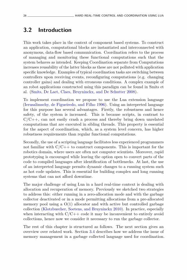
26 HARD REAL-TIME CONTROL AND COORDINATION USING LUA
3.2 Introduction
This work takes place in the context of component based systems. To constructan application, computational blocks are instantiated and interconnected withanonymous, data-flow based communication. Coordination refers to the processof managing and monitoring these functional computations such that thesystem behaves as intended. Keeping Coordination separate from Computationsincreases reusability of the latter blocks as these are not polluted with applicationspecific knowledge. Examples of typical coordination tasks are switching betweencontrollers upon receiving events, reconfiguring computations (e.g. changingcontroller gains) and dealing with erroneous conditions. A complex example ofan robot applications constructed using this paradigm can be found in Smits etal. (Smits, De Laet, Claes, Bruyninckx, and De Schutter 2008).
To implement coordination we propose to use the Lua extension language(Ierusalimschy, de Figueiredo, and Filho 1996). Using an interpreted languagefor this purpose has several advantages. Firstly, the robustness and hencesafety, of the system is increased. This is because scripts, in contrast toC/C++, can not easily crash a process and thereby bring down unrelatedcomputations that are executed in sibling threads. This property is essentialfor the aspect of coordination, which, as a system level concern, has higherrobustness requirements than regular functional computations.
Secondly, the use of a scripting language facilitates less experienced programmersnot familiar with C/C++ to construct components. This is important for therobotics domain, where users are often not computer scientists. Moreover, rapidprototyping is encouraged while leaving the option open to convert parts of thecode to compiled languages after identification of bottlenecks. At last, the useof an interpreted language permits dynamic changes to a running system suchas hot code updates. This is essential for building complex and long runningsystems that can not afford downtime.
The major challenge of using Lua in a hard real-time context is dealing withallocation and recuperation of memory. Previously we sketched two strategiesto address this: either running in a zero-allocation mode and with the garbagecollector deactivated or in a mode permitting allocations from a pre-allocatedmemory pool using a O(1) allocator and with active but controlled garbagecollection (Klotzbuecher, Soetens, and Bruyninckx 2010). In practice, especiallywhen interacting with C/C++ code it may be inconvenient to entirely avoidcollections, hence now we consider it necessary to run the garbage collector.
The rest of this chapter is structured as follows. The next section gives anoverview over related work. Section 3.4 describes how we address the issue ofmemory management in a garbage collected language used for coordination.
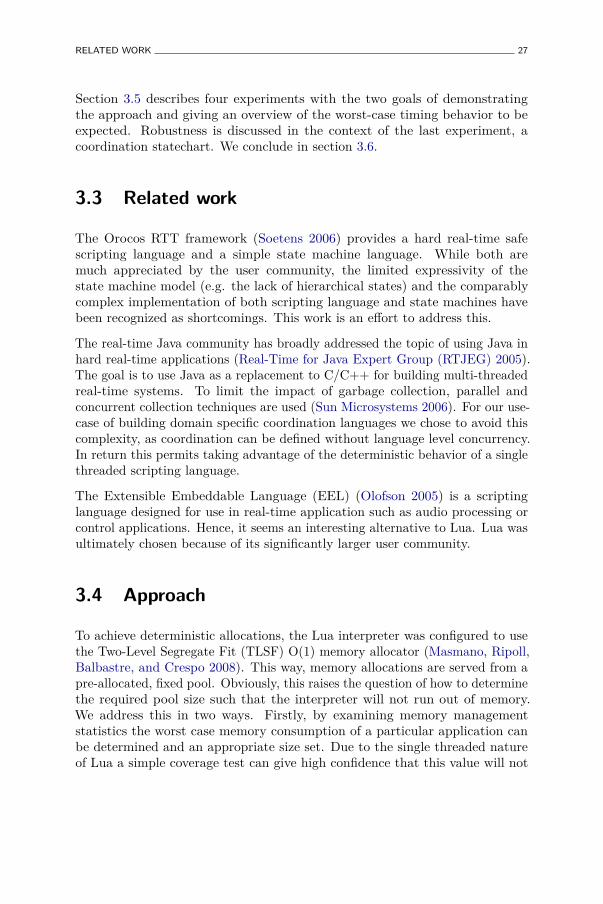
RELATED WORK 27
Section 3.5 describes four experiments with the two goals of demonstratingthe approach and giving an overview of the worst-case timing behavior to beexpected. Robustness is discussed in the context of the last experiment, acoordination statechart. We conclude in section 3.6.
3.3 Related work
The Orocos RTT framework (Soetens 2006) provides a hard real-time safescripting language and a simple state machine language. While both aremuch appreciated by the user community, the limited expressivity of thestate machine model (e.g. the lack of hierarchical states) and the comparablycomplex implementation of both scripting language and state machines havebeen recognized as shortcomings. This work is an effort to address this.
The real-time Java community has broadly addressed the topic of using Java inhard real-time applications (Real-Time for Java Expert Group (RTJEG) 2005).The goal is to use Java as a replacement to C/C++ for building multi-threadedreal-time systems. To limit the impact of garbage collection, parallel andconcurrent collection techniques are used (Sun Microsystems 2006). For our use-case of building domain specific coordination languages we chose to avoid thiscomplexity, as coordination can be defined without language level concurrency.In return this permits taking advantage of the deterministic behavior of a singlethreaded scripting language.
The Extensible Embeddable Language (EEL) (Olofson 2005) is a scriptinglanguage designed for use in real-time application such as audio processing orcontrol applications. Hence, it seems an interesting alternative to Lua. Lua wasultimately chosen because of its significantly larger user community.
3.4 Approach
To achieve deterministic allocations, the Lua interpreter was configured to usethe Two-Level Segregate Fit (TLSF) O(1) memory allocator (Masmano, Ripoll,Balbastre, and Crespo 2008). This way, memory allocations are served from apre-allocated, fixed pool. Obviously, this raises the question of how to determinethe required pool size such that the interpreter will not run out of memory.We address this in two ways. Firstly, by examining memory managementstatistics the worst case memory consumption of a particular application canbe determined and an appropriate size set. Due to the single threaded natureof Lua a simple coverage test can give high confidence that this value will not
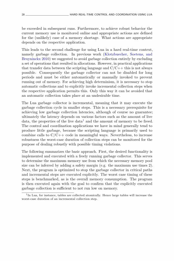
28 HARD REAL-TIME CONTROL AND COORDINATION USING LUA
be exceeded in subsequent runs. Furthermore, to achieve robust behavior thecurrent memory use is monitored online and appropriate actions are definedfor the (unlikely) case of a memory shortage. What actions are appropriatedepends on the respective application.
This leads to the second challenge for using Lua in a hard real-time context,namely garbage collection. In previous work (Klotzbuecher, Soetens, andBruyninckx 2010) we suggested to avoid garbage collection entirely by excludinga set of operations that resulted in allocations. However, in practical applicationsthat transfer data between the scripting language and C/C++ this is not alwayspossible. Consequently the garbage collector can not be disabled for longperiods and must be either automatically or manually invoked to preventrunning out of memory. For achieving high determinism, it is necessary to stopautomatic collections and to explicitly invoke incremental collection steps whenthe respective application permits this. Only this way it can be avoided thatan automatic collection takes place at an undesirable time.
The Lua garbage collector is incremental, meaning that it may execute thegarbage collection cycle in smaller steps. This is a necessary prerequisite forachieving low garbage collection latencies, although of course no guarantee;ultimately the latency depends on various factors such as the amount of livedata, the properties of the live data1 and the amount of memory to be freed.The control and coordination applications we have in mind generally tend toproduce little garbage, because the scripting language is primarily used tocombine calls to C/C++ code in meaningful ways. Nevertheless, to increaserobustness the worst-case duration of collection steps can be monitored for thepurpose of dealing robustly with possible timing violations.
The following summarizes the basic approach. First, the desired functionality isimplemented and executed with a freely running garbage collector. This servesto determine the maximum memory use from which the necessary memory poolsize can be inferred by adding a safety margin (e.g. the maximum use times 2).Next, the program is optimized to stop the garbage collector in critical pathsand incremental steps are executed explicitly. The worst case timing of thesesteps is benchmarked, as is the overall memory consumption. The programis then executed again with the goal to confirm that the explicitly executedgarbage collection is sufficient to not run low on memory.
1In Lua, for instance, tables are collected atomically. Hence large tables will increase theworst-case duration of an incremental collection step.
EXPERIMENTS 29
3.5 Experiments
In this section we describe the experiments carried out to assess worst-caselatencies and overhead of Lua compared to using C/C++ implementations. Alltests are executed using Xenomai (Gerum 2004) (v2.5.6 on Linux-2.6.37) ona Dell Latitude E6410 with an Intel i7 quad core CPU and 8 GiB of RAM,with real-time priorities, current and future memory locked in RAM and underload.2 Apart from the cyclictest all tests are implemented using the OrocosRTT (Soetens 2006) framework. The source code is available here3.
3.5.1 Lua Cyclictest
The first test is a Lua implementation of the well known cyclictest (Gleixner2011). This test measures the latency between scheduled and real wake up timeof a thread after a request to sleep using clock_nanosleep(2). The test isrepeated with different, absolute sleep times. For the Lua version, the test is runwith three different garbage collector modes: Free, Off or Controlled. Freemeans the garbage collector is not stopped and hence automatically reclaimsmemory (the Lua default). Off means the allocator is stopped completely4
by calling collectgarbage(’stop’). Controlled means that the collector isstopped and an incremental garbage collection step is executed after computingthe wake up time statistics (this way the step does not add to the latency aslong as the collection completes before the next wake up).
The purpose of this test is to compare the average and worst case latenciesbetween the Lua and C version and to investigate the impact of the garbagecollector in different modes.
Results Table 3.1 summarizes the results of the cyclictest experiments. Eachfield contains two values, the average (“a”) and worst case (“w”) latency givenin microseconds, that were obtained after fifteen minutes of execution.
Comparing the C cyclictest with the Lua variants as expected indicates thatthere is an overhead of using the scripting language. The differences between thethree garbage collection modes are less visible. Table 3.2 shows the average ofthe worst case latencies in microseconds and expressed as a ratio to the average
2ping -f localhost, and while true; do ls -R /; done.3http://people.mech.kuleuven.be/~mklotzbucher/2011-09-19-rtlws2011/source.tar.
bz24This is possible because the allocations are so few that the system does not run out of
memory within the duration of the test.
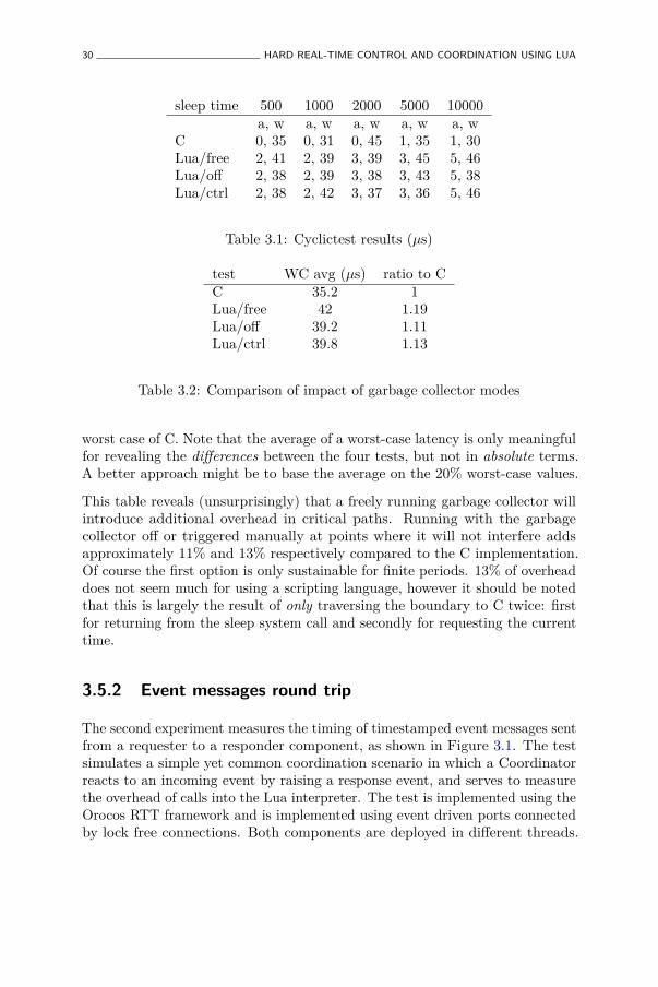
30 HARD REAL-TIME CONTROL AND COORDINATION USING LUA
sleep time 500 1000 2000 5000 10000a, w a, w a, w a, w a, w
C 0, 35 0, 31 0, 45 1, 35 1, 30Lua/free 2, 41 2, 39 3, 39 3, 45 5, 46Lua/off 2, 38 2, 39 3, 38 3, 43 5, 38Lua/ctrl 2, 38 2, 42 3, 37 3, 36 5, 46
Table 3.1: Cyclictest results (µs)
test WC avg (µs) ratio to CC 35.2 1Lua/free 42 1.19Lua/off 39.2 1.11Lua/ctrl 39.8 1.13
Table 3.2: Comparison of impact of garbage collector modes
worst case of C. Note that the average of a worst-case latency is only meaningfulfor revealing the differences between the four tests, but not in absolute terms.A better approach might be to base the average on the 20% worst-case values.
This table reveals (unsurprisingly) that a freely running garbage collector willintroduce additional overhead in critical paths. Running with the garbagecollector off or triggered manually at points where it will not interfere addsapproximately 11% and 13% respectively compared to the C implementation.Of course the first option is only sustainable for finite periods. 13% of overheaddoes not seem much for using a scripting language, however it should be notedthat this is largely the result of only traversing the boundary to C twice: firstfor returning from the sleep system call and secondly for requesting the currenttime.
3.5.2 Event messages round trip
The second experiment measures the timing of timestamped event messages sentfrom a requester to a responder component, as shown in Figure 3.1. The testsimulates a simple yet common coordination scenario in which a Coordinatorreacts to an incoming event by raising a response event, and serves to measurethe overhead of calls into the Lua interpreter. The test is implemented using theOrocos RTT framework and is implemented using event driven ports connectedby lock free connections. Both components are deployed in different threads.
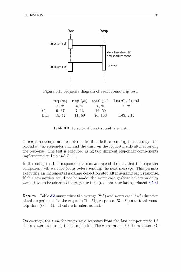
EXPERIMENTS 31
Req Resp
gcstep
store timestamp t2
and send response
timestamp t1
timestamp t3
Figure 3.1: Sequence diagram of event round trip test.
req (µs) resp (µs) total (µs) Lua/C of totala, w a, w a, w a, w
C 9, 37 7, 18 16, 50 -Lua 15, 47 11, 59 26, 106 1.63, 2.12
Table 3.3: Results of event round trip test.
Three timestamps are recorded: the first before sending the message, thesecond at the responder side and the third on the requester side after receivingthe response. The test is executed using two different responder componentsimplemented in Lua and C++.
In this setup the Lua responder takes advantage of the fact that the requestercomponent will wait for 500us before sending the next message. This permitsexecuting an incremental garbage collection step after sending each response.If this assumption could not be made, the worst-case garbage collection delaywould have to be added to the response time (as is the case for experiment 3.5.3).
Results Table 3.3 summarizes the average (“a”) and worst-case (“w”) durationof this experiment for the request (t2 − t1), response (t3 − t2) and total roundtrip time (t3 − t1); all values in microseconds.
On average, the time for receiving a response from the Lua component is 1.6times slower than using the C responder. The worst case is 2.2 times slower. Of
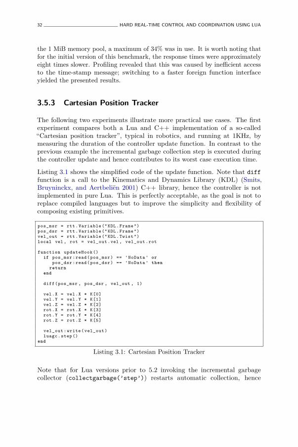
32 HARD REAL-TIME CONTROL AND COORDINATION USING LUA
the 1 MiB memory pool, a maximum of 34% was in use. It is worth noting thatfor the initial version of this benchmark, the response times were approximatelyeight times slower. Profiling revealed that this was caused by inefficient accessto the time-stamp message; switching to a faster foreign function interfaceyielded the presented results.
3.5.3 Cartesian Position Tracker
The following two experiments illustrate more practical use cases. The firstexperiment compares both a Lua and C++ implementation of a so-called“Cartesian position tracker”, typical in robotics, and running at 1KHz, bymeasuring the duration of the controller update function. In contrast to theprevious example the incremental garbage collection step is executed duringthe controller update and hence contributes to its worst case execution time.
Listing 3.1 shows the simplified code of the update function. Note that difffunction is a call to the Kinematics and Dynamics Library (KDL) (Smits,Bruyninckx, and Aertbeliën 2001) C++ library, hence the controller is notimplemented in pure Lua. This is perfectly acceptable, as the goal is not toreplace compiled languages but to improve the simplicity and flexibility ofcomposing existing primitives.
pos_msr = rtt. Variable (" KDL. Frame ")pos_dsr = rtt. Variable (" KDL. Frame ")vel_out = rtt. Variable (" KDL. Twist ")local vel , rot = vel_out .vel , vel_out .rot
function updateHook ()if pos_msr :read( pos_msr ) == 'NoData ' or
pos_dsr :read( pos_dsr ) == 'NoData ' thenreturn
end
diff(pos_msr , pos_dsr , vel_out , 1)
vel.X = vel.X * K[0]vel.Y = vel.Y * K[1]vel.Z = vel.Z * K[2]rot.X = rot.X * K[3]rot.Y = rot.Y * K[4]rot.Z = rot.Z * K[5]
vel_out : write ( vel_out )luagc .step ()
end
Listing 3.1: Cartesian Position Tracker
Note that for Lua versions prior to 5.2 invoking the incremental garbagecollector (collectgarbage(’step’)) restarts automatic collection, hence
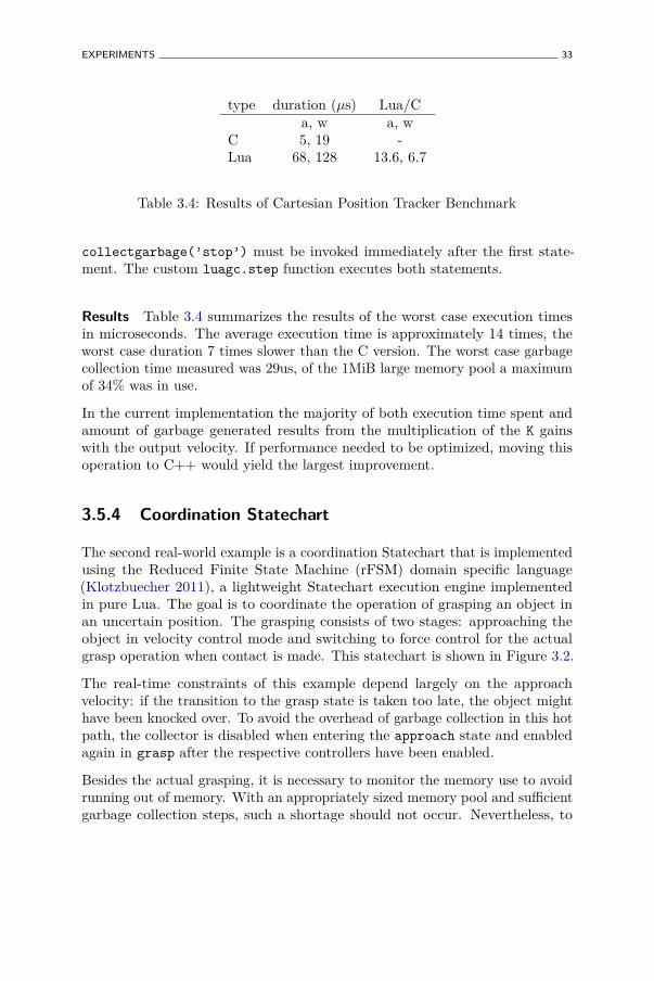
EXPERIMENTS 33
type duration (µs) Lua/Ca, w a, w
C 5, 19 -Lua 68, 128 13.6, 6.7
Table 3.4: Results of Cartesian Position Tracker Benchmark
collectgarbage(’stop’) must be invoked immediately after the first state-ment. The custom luagc.step function executes both statements.
Results Table 3.4 summarizes the results of the worst case execution timesin microseconds. The average execution time is approximately 14 times, theworst case duration 7 times slower than the C version. The worst case garbagecollection time measured was 29us, of the 1MiB large memory pool a maximumof 34% was in use.
In the current implementation the majority of both execution time spent andamount of garbage generated results from the multiplication of the K gainswith the output velocity. If performance needed to be optimized, moving thisoperation to C++ would yield the largest improvement.
3.5.4 Coordination Statechart
The second real-world example is a coordination Statechart that is implementedusing the Reduced Finite State Machine (rFSM) domain specific language(Klotzbuecher 2011), a lightweight Statechart execution engine implementedin pure Lua. The goal is to coordinate the operation of grasping an object inan uncertain position. The grasping consists of two stages: approaching theobject in velocity control mode and switching to force control for the actualgrasp operation when contact is made. This statechart is shown in Figure 3.2.
The real-time constraints of this example depend largely on the approachvelocity: if the transition to the grasp state is taken too late, the object mighthave been knocked over. To avoid the overhead of garbage collection in this hotpath, the collector is disabled when entering the approach state and enabledagain in grasp after the respective controllers have been enabled.
Besides the actual grasping, it is necessary to monitor the memory use to avoidrunning out of memory. With an appropriately sized memory pool and sufficientgarbage collection steps, such a shortage should not occur. Nevertheless, to
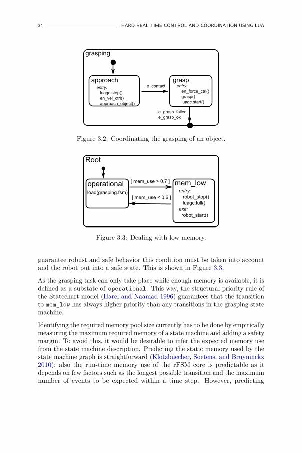
34 HARD REAL-TIME CONTROL AND COORDINATION USING LUA
grasping
approachentry:
luagc.step()
en_vel_ctrl()
approach_object()
e_contact
graspentry:
en_force_ctrl()
grasp()
luagc.start()
e_grasp_failed
e_grasp_ok
Figure 3.2: Coordinating the grasping of an object.
Root
operational mem_lowentry: robot_stop() luagc.full() exit: robot_start()
[ mem_use > 0.7 ]
[ mem_use < 0.6 ]load(grasping.fsm)
Figure 3.3: Dealing with low memory.
guarantee robust and safe behavior this condition must be taken into accountand the robot put into a safe state. This is shown in Figure 3.3.
As the grasping task can only take place while enough memory is available, it isdefined as a substate of operational. This way, the structural priority rule ofthe Statechart model (Harel and Naamad 1996) guarantees that the transitionto mem_low has always higher priority than any transitions in the grasping statemachine.
Identifying the required memory pool size currently has to be done by empiricallymeasuring the maximum required memory of a state machine and adding a safetymargin. To avoid this, it would be desirable to infer the expected memory usefrom the state machine description. Predicting the static memory used by thestate machine graph is straightforward (Klotzbuecher, Soetens, and Bruyninckx2010); also the run-time memory use of the rFSM core is predictable as itdepends on few factors such as the longest possible transition and the maximumnumber of events to be expected within a time step. However, predicting
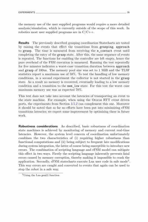
EXPERIMENTS 35
the memory use of the user supplied programs would require a more detailedanalysis/simulation, which is currently outside of the scope of this work. Inrobotics most user supplied programs are in C/C++.
Results The previously described grasping coordination Statecharts are testedby raising the events that effect the transitions from grasping, approachto grasp. The time is measured from receiving the e_contact event untilcompleting the entry of the grasp state. After this, the same sequence of eventsis repeated. The functions for enabling the controller are left empty, hence thepure overhead of the FSM execution is measured. Running the test repeatedlyfor five minutes indicates a worst-case transition duration between approachand grasp of 180us. The memory pool size was set to 1 MiB and the TLSFstatistics report a maximum use of 58%. To test the handling of low memoryconditions, in a second experiment the collector is not started in the graspstate. As a result no memory is recovered, eventually leading to a low memorycondition and a transition to the mem_low state. For this test the worst casemaximum memory use was as expected 70%.
This test does not take into account the latencies of transporting an event tothe state machine. For example, when using the Orocos RTT event drivenports, the experiments from Section 3.5.2 can complement this one. Moreoverit should be noted that so far no efforts have been put into minimizing rFSMtransitions latencies; we expect some improvement by optimizing these in futurework.
Robustness considerations As described, basic robustness of coordinationstate machines is achieved by monitoring of memory and current real-timelatencies. However, the system level concern of coordination unfortunatelycombines the two characteristics of (i) requiring higher robustness thanfunctional computations and (ii) being subject to frequent late modificationsduring system integration, the latter of course being susceptible to introduce newerrors. The combination of scripting language and rFSM model can mitigatethis effect in two ways. Firstly the scripting language inherently prevents fatalerrors caused by memory corruption, thereby making it impossible to crash theapplication. Secondly, rFSM statecharts execute Lua user code in safe mode5.This way errors are caught and converted to events that again can be used tostop the robot in a safe way.
5Using the Lua pcall function

36 HARD REAL-TIME CONTROL AND COORDINATION USING LUA
3.6 Conclusions
We have described how the Lua programming language can be used for hardreal-time coordination and control by making use of an O(1) memory allocator,experimentally determining worst-case memory use and manually optimizinggarbage collection to not interfere in critical paths. Several experiments arecarried out to determine worst-case latencies and to illustrate the approach.
As usual, benchmark results should be judged with caution and mainly serveto remind that appropriate validation should be repeated for each critical use.In particular when real-time allocation and collection is involved, run timevalidation of real-time constraints must be considered as an integral part of theapplication.
The major shortcoming of the current approach is that worst-case memory usecan be difficult to predict. To deal with this we currently allocate additionalsafety margins. As the overall memory usage of the Lua language is comparablysmall, such a measure will be acceptable for many systems, save the veryresource constrained.
To conclude, we believe the results demonstrate the feasibility of our approachto use a scripting language for hard real-time control and coordination andpermits to significantly improve robustness and safety of a system. The priceof these improvements are (i) increased, yet bounded worst-case latencies, (ii)additional computational overhead, as well as (iii) requiring extra effort such asmanual scheduling of garbage collection. In summary, we believe this constitutesa modern and practical approach to building hard real-time systems that shiftsthe focus from lowest possible latency to sufficient latency while maximizingreliability.
Future work will take place in two directions. On the high level we are exploringhow to automatically generate executable domain specific languages from formaldescriptions. Implementationwise we intend to investigate if and how thepresented worst case timing behavior can be improved by using the luajit (Pall2011) implementation, a high performance just-in-time compiler for Lua.
Chapter 4
Coordinating Robotic Tasksand Systems using rFSMStatecharts∗
4.1 Abstract
Coordination is a system-level concern defining execution and interactionsemantics of functional computations. Separating coordination from functionalcomputations is a key principle for building complex, robust and reusable roboticsystems. This work introduces a minimal variant of Harel statecharts calledrFSM designed to model coordination of robotic tasks and systems with aminimal number of semantic primitives. Firstly, the semantics of the rFSMlanguage are derived by analyzing state-of-the-art discrete event models andimplementations and extracting a motivated and semantically well-definedsubset that is considered best practice for the domain of robotic coordination.Secondly, a real-time capable reference implementation of rFSM is presented,which has been loosely integrated into the OROCOS/RTT framework. Theapplication of rFSM is illustrated using a detailed description of a dual robotcoordination problem. Lastly, several best practices and patterns are presentedwith the goal of i) supporting development of robust Coordination models,ii) illustrating how limitations of the statechart model can be overcome by
∗This chapter is based on Klotzbücher, M., Bruyninckx, H. (2012). Coordinating RoboticTasks and Systems with rFSM Statecharts. JOSER: Journal of Software Engineering forRobotics, 3 (1), 28-56.
37

38 COORDINATING ROBOTIC TASKS AND SYSTEMS USING RFSM STATECHARTS
extending the execution semantics, and iii) offering guidance in designing purecoordination components that optimize reusability.
4.2 Introduction
The design of todays complex robot systems is driven by multiple and oftenpartically conflicting requirements. Apart from the primary functionality, theserequirements commonly include the need to reuse existing parts, for the systemto behave robust or safe in the presence of errors or to facilitate reconfigurationof the system due to changed requirements.
The extent to which these goals can be fulfilled is strongly influenced bythe approach used to divide the system into parts. This work builds onthe suggestion of Radestock and Eisenbach (Radestock and Eisenbach 1996)to separate the systems according to the four concerns of Communication,Computation, Configuration and Coordination: Communication defines howentities communicate. Computation defines the functionality and hence whatis communicated. Configuration defines how computations are configured andwhich computations communicate with each other. Lastly, Coordination isresponsible for managing the individual entities such that the system as a wholebehaves as specified.
Most of today’s robotic software frameworks support the separation ofCommunication, Computation and Configuration. For example, the OrocosRTT framework (Soetens 2006) permits to separately specify communicationconnections between components and the respective parameters such as bufferingpolicies. Component configurations can be defined separately and need only beapplied to the respective component instances at runtime. Similarly, the ROSframework (Willow Garage 2008) permits separate storage of node configurationusing the so called parameter service.
In contrast, the concern of Coordination is not yet recognized as a first-classdesign aspect in many of today’s complex robotic systems. Instead, Coordinationis often implicitly incorporated into Computation and Communication. Forexample, in the Orocos RTT framework prior to version 2, coordination wasoften realized using the RTT::Event mechanism. Using this, a computationalcomponent declares the ability to raise an event represented as a parametrizedfunction. Other computational components register handlers matching the eventinterface, which are then called to be notified of the event occurrence. As aresult of this tight coupling, the event recipient is polluted with system-levelcoordination that limits its reusability. Moreoever, such implicit coordination
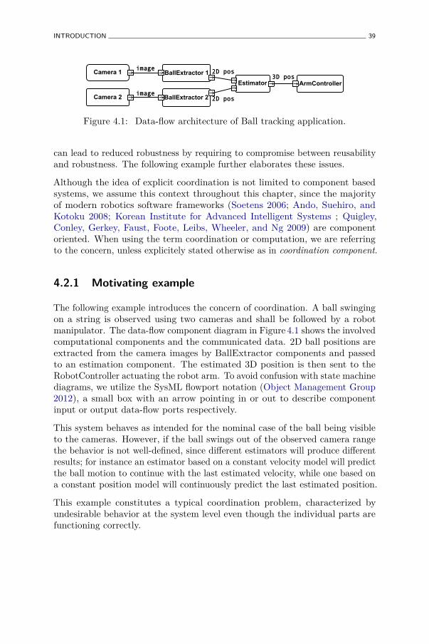
INTRODUCTION 39
Camera 1
Camera 2
image
2D pos
3D pos
image
BallExtractor 1
BallExtractor 2
2D pos
Estimator ArmController
Figure 4.1: Data-flow architecture of Ball tracking application.
can lead to reduced robustness by requiring to compromise between reusabilityand robustness. The following example further elaborates these issues.
Although the idea of explicit coordination is not limited to component basedsystems, we assume this context throughout this chapter, since the majorityof modern robotics software frameworks (Soetens 2006; Ando, Suehiro, andKotoku 2008; Korean Institute for Advanced Intelligent Systems ; Quigley,Conley, Gerkey, Faust, Foote, Leibs, Wheeler, and Ng 2009) are componentoriented. When using the term coordination or computation, we are referringto the concern, unless explicitely stated otherwise as in coordination component.
4.2.1 Motivating example
The following example introduces the concern of coordination. A ball swingingon a string is observed using two cameras and shall be followed by a robotmanipulator. The data-flow component diagram in Figure 4.1 shows the involvedcomputational components and the communicated data. 2D ball positions areextracted from the camera images by BallExtractor components and passedto an estimation component. The estimated 3D position is then sent to theRobotController actuating the robot arm. To avoid confusion with state machinediagrams, we utilize the SysML flowport notation (Object Management Group2012), a small box with an arrow pointing in or out to describe componentinput or output data-flow ports respectively.
This system behaves as intended for the nominal case of the ball being visibleto the cameras. However, if the ball swings out of the observed camera rangethe behavior is not well-defined, since different estimators will produce differentresults; for instance an estimator based on a constant velocity model will predictthe ball motion to continue with the last estimated velocity, while one based ona constant position model will continuously predict the last estimated position.
This example constitutes a typical coordination problem, characterized byundesirable behavior at the system level even though the individual parts arefunctioning correctly.
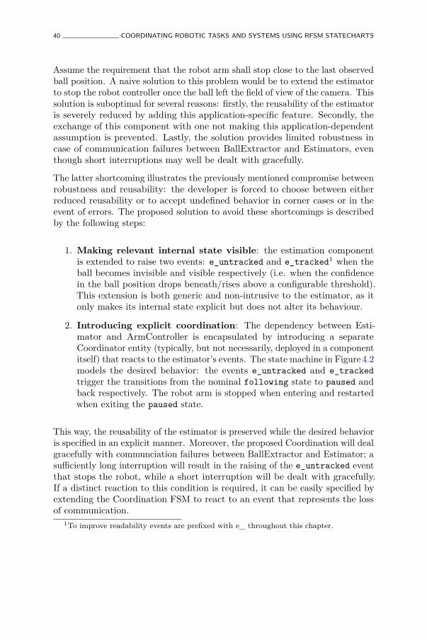
40 COORDINATING ROBOTIC TASKS AND SYSTEMS USING RFSM STATECHARTS
Assume the requirement that the robot arm shall stop close to the last observedball position. A naive solution to this problem would be to extend the estimatorto stop the robot controller once the ball left the field of view of the camera. Thissolution is suboptimal for several reasons: firstly, the reusability of the estimatoris severely reduced by adding this application-specific feature. Secondly, theexchange of this component with one not making this application-dependentassumption is prevented. Lastly, the solution provides limited robustness incase of communication failures between BallExtractor and Estimators, eventhough short interruptions may well be dealt with gracefully.
The latter shortcoming illustrates the previously mentioned compromise betweenrobustness and reusability: the developer is forced to choose between eitherreduced reusability or to accept undefined behavior in corner cases or in theevent of errors. The proposed solution to avoid these shortcomings is describedby the following steps:
1. Making relevant internal state visible: the estimation componentis extended to raise two events: e_untracked and e_tracked1 when theball becomes invisible and visible respectively (i.e. when the confidencein the ball position drops beneath/rises above a configurable threshold).This extension is both generic and non-intrusive to the estimator, as itonly makes its internal state explicit but does not alter its behaviour.
2. Introducing explicit coordination: The dependency between Esti-mator and ArmController is encapsulated by introducing a separateCoordinator entity (typically, but not necessarily, deployed in a componentitself) that reacts to the estimator’s events. The state machine in Figure 4.2models the desired behavior: the events e_untracked and e_trackedtrigger the transitions from the nominal following state to paused andback respectively. The robot arm is stopped when entering and restartedwhen exiting the paused state.
This way, the reusability of the estimator is preserved while the desired behavioris specified in an explicit manner. Moreover, the proposed Coordination will dealgracefully with communciation failures between BallExtractor and Estimator; asufficiently long interruption will result in the raising of the e_untracked eventthat stops the robot, while a short interruption will be dealt with gracefully.If a distinct reaction to this condition is required, it can be easily specified byextending the Coordination FSM to react to an event that represents the lossof communication.
1To improve readability events are prefixed with e_ throughout this chapter.
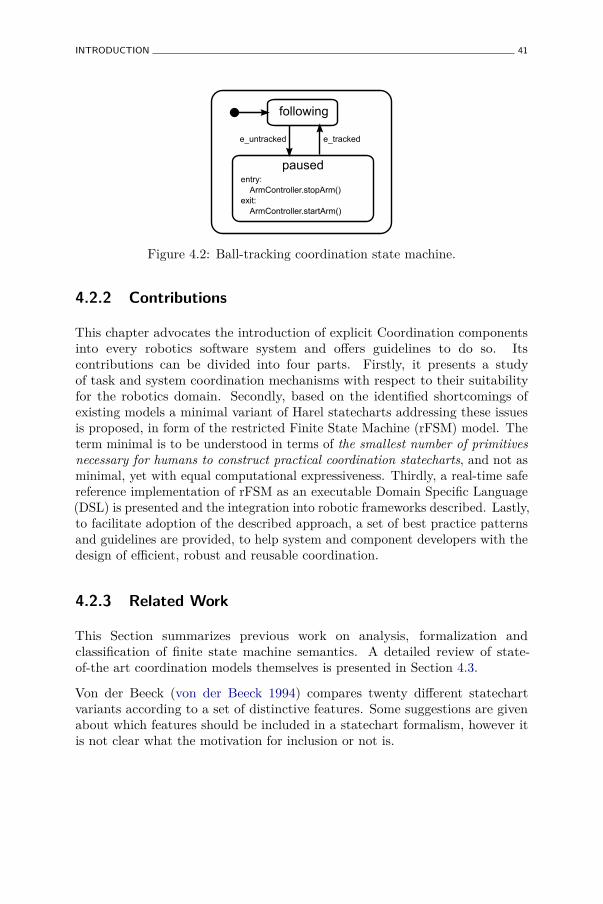
INTRODUCTION 41
following
pausedentry: ArmController.stopArm()exit: ArmController.startArm()
e_untracked e_tracked
Figure 4.2: Ball-tracking coordination state machine.
4.2.2 Contributions
This chapter advocates the introduction of explicit Coordination componentsinto every robotics software system and offers guidelines to do so. Itscontributions can be divided into four parts. Firstly, it presents a studyof task and system coordination mechanisms with respect to their suitabilityfor the robotics domain. Secondly, based on the identified shortcomings ofexisting models a minimal variant of Harel statecharts addressing these issuesis proposed, in form of the restricted Finite State Machine (rFSM) model. Theterm minimal is to be understood in terms of the smallest number of primitivesnecessary for humans to construct practical coordination statecharts, and not asminimal, yet with equal computational expressiveness. Thirdly, a real-time safereference implementation of rFSM as an executable Domain Specific Language(DSL) is presented and the integration into robotic frameworks described. Lastly,to facilitate adoption of the described approach, a set of best practice patternsand guidelines are provided, to help system and component developers with thedesign of efficient, robust and reusable coordination.
4.2.3 Related Work
This Section summarizes previous work on analysis, formalization andclassification of finite state machine semantics. A detailed review of state-of-the art coordination models themselves is presented in Section 4.3.
Von der Beeck (von der Beeck 1994) compares twenty different statechartvariants according to a set of distinctive features. Some suggestions are givenabout which features should be included in a statechart formalism, however itis not clear what the motivation for inclusion or not is.

42 COORDINATING ROBOTIC TASKS AND SYSTEMS USING RFSM STATECHARTS
Eshuis (Eshuis 2009) identifies a set of constraints for which subsets of the threecommon statechart semantics—STATEMATE, Fixpoint and UML—behaveidentically. Besides suggesting improvements to statechart semantics, this workdiffers significantly from ours that is focussed on using statecharts for theparticular purpose of coordination.
Breen (Breen 2004) identifies several shortcomings of Harel statecharts forthe purpose of system specification. Most issues are related to parallel states(modeling concurrency), and hence do not affect our rFSM model that excludesthis model element. Breen observes that the difficulty of understanding thecomplex relationship between parallel states (which is a consequence of broadcastevent communication and the inevitable non-determinism of communicationdelays) can be avoided by simply using separate statecharts instead of parallelstates. This observation, albeit for different reasons discussed in Section 4.8,confirms our approach to exclude the parallel state element. Furthermore, Breendescribes the following shortcoming of the statechart model that is related tohierarchy and also affects the rFSM model: by observing just the graphicalmodel of a state machine, the designers’ motivation for using hierarchy is notalways obvious. This is due to multiple use-cases for using hierarchical states. Tothis end, the following use-cases are identified: clustering, abstraction, transitiondependence, state variable instantiation and expression of constraints. Breenconcludes by pointing out that the described problems will not be significant inrelatively simple models.
Simons (Simons 2000) examines the semantics of UML State machines andsuggests a revised interpretation. Extensions are identified that can beconsidered either redundant or harmful to the compositional properties ofthe model. The latter class include the inversion of conflict resolutionpriorities in UML with respect to Harel statecharts and the special semanticsof completion transitions. Moreover, the revised semantics attempt to improvethe differentiation between statecharts and flowcharts. The rFSM semanticsdescribed later follow several, but not all, of these suggestions.
4.2.4 Outline
The rest of this work is structured as follows. Section 4.3 reviews existingcoordination models and implementations. After briefly introducing the rFSMmodel in Section 4.4, the insights gained from these reviews are used in thediscussion of structural, execution and event semantics in Sections 4.5–4.7, thatultimately lead to the derivation of rFSM. Section 4.8 is dedicated to motivatethe exclusion of the widely used parallel state element from the rFSM model.Section 4.9 describes the reference implementation that was developed. Best
REVIEW OF COORDINATION MODELS 43
practices and patterns are described in Section 4.10. Section 4.11 presents adetailed example that illustrates step by step the process of developing thecoordination for a dual robot haptic coupling system. We provide a discussionof our contributions in Section 4.12, and conclude in Section 4.13.
4.3 Review of Coordination Models
4.3.1 Classical Finite State Automatons
Finite state machines (FSM), sometimes called finite state automata, aremathematical models of behaviour. FSM are widely used, ranging fromapplication in computational linguistics to language parsing and artificialintelligence. A FSM consists of a finite set of states connected by transitions.
Commonly, two types of FSM are distinguished: acceptors and transducers.Acceptors, which are also known as recognisers, return a binary result ofwhether or not a certain input was recognized, and are mostly used in languagerecognition. Transducers can generate output with the help of actions, andcan be divided into two classes: Moore and Mealy state machines. In theMoore model, the output is a function only of the current state, while in theMealy model the output is a function of the input and the current state. Whileboth models are equally expressive, in practice often formalism as UML2 statemachines are used, where the output can be a function only of state or of stateand input.
4.3.2 Harel Statecharts
The Harel statechart (Harel 1987; Harel and Naamad 1996) is the first statemachine based formalism to extend classical flat automatons with hierarchy,parallelism and broadcast events. Hierarchical states may contain statesthemselves, thereby facilitating abstraction and modularization of larger models.Additionally, hierarchy enables transition prioritisation using a strategy namedstructural priority: in case of two or more conflicting transitions the one with theleast nested source state (within the global hierarchy) takes priority. Parallelismpermits substates contained in a so called AND state to be simultaneously active.Broadcast events are a more controversial feature (Breen 2004) causing thatevents raised in one sub-statechart (such as a parallel substate) are observed andhence can trigger transitions throughout the entire statechart, thus violatingthe scope introduced by each level of hierarchy. The aforementioned controversy
44 COORDINATING ROBOTIC TASKS AND SYSTEMS USING RFSM STATECHARTS
arises from the fact that the behaviour of a large statechart can becomeconsiderably intricate, especially in combination with statechart parallelism.
The quasi-standard statechart semantics are documented and implemented inthe STATEMATE model and tool (Harel and Naamad 1996), (Harel, Lanchover,Naamad, Pnueli, Politi, Sherman, Shtull-Trauring, and Trakhtenbrot 1990).Apart from STATEMATE, numerous other variations exist (von der Beeck 1994),which is to some extent a consequence of the fact that a detailed description ofstatechart semantics was only provided years after the initial proposal. Today,the most widely used variants are UML2 (Object Management Group 2009)state machines, the W3C State Chart XML (SCXML) (W3C 2010) model andthe commercial Simulink Stateflow tool of the MathWorks (MathWorks ).
4.3.3 OMG UML State Machines
UML state machines (Object Management Group 2011) are derived from Harelstatecharts and introduce various syntactic and semantic extensions with thegoal to enable application in an object oriented context. One limitation of UMLin general are the so-called semantic variation points that intentionally leavethe precise semantics of model entities open; for example, the order in whichevents are dequeued from the internal event queue is left undefined. This is togive tool-implementers of the standard more liberty to define these semanticsthemselves. As a consequence, practically all implementations of UML statemachines yield incompatible execution behaviour, and the precise semanticsoften remain hidden in the implementation of the tool.
A second issue with UML statecharts arises from semantic deviations madefrom Harel statecharts with the goal to make UML statecharts behave morelike objects as in the object-oriented programming paradigm; the consequencesare discussed in Section 4.6.
In spite of these limitations, UML state machines are widely used and supportedby many modeling tools. Hence, the statecharts proposed in this workfollow these semantics wherever appropriate, in order to facilitate automatictransformation of UML state machines to rFSM models.
4.3.4 Statecharts in Robotics
Statecharts have been previously used in robotic systems. Merz et. al. (Merz,Rudol, and Wzorek 2006) use an augmented flavor of Statecharts called ExtendedState Machines (ESM) to specify control and data flow in a robotic controlframework. In contrast to our approach that advocates the separation of
REVIEW OF COORDINATION MODELS 45
the concerns of computation and coordination, ESM states tightly couplecontrol and data-flow by permitting these to also output data via data ports.While this combination might be convenient, reusability is reduced by tightlycoupling application coordination with functional computations. Billington et.al. (Billington, Estivill-Castro, Hexel, and Rock 2010) propose an approachto requirement engineering using UML Statemachines that are extended withnon-monotonic logic for describing domain knowledge. This logic is used todescribe the behavior of single FSM and the corresponding predicates to be usedas guard conditions. This formulation then allows to validate certain propertiessuch as the exclusivity of guards. Similarly to our approach, the behavior ofthe system is defined by multiple interacting state machines, though the focusis on modeling complex high-level behavioral protocols. In contrast, our workis concerned with preserving reusability of computational components.
4.3.5 IEC 61131-3 Sequential Function Charts
Sequential function charts (SFC) are a PLC programming language specified inthe IEC 61131-3 (International Electrotechnical Commission 2003) standard.The SFC language is based on the Grafcet language (David and Alla 1992),which in turn is derived from Petri nets. This heritage reflects in the SFCsemantics that generally impose less constraints with respect to hierarchies andpermitted transitions.
SFCs are constructed by linking steps with transitions. Each transition has acondition that defines when control passes to the next step. Simultaneousdivergence permits to activate two successor states simultaneously whilesimultaneous convergence permits to synchronize the parallel execution again.In order to specify the in-step behaviour, steps can be associated with Actionblocks. Action qualifiers define the exact manner in which the action is executed.Example qualifiers are N (non-stored) for executing an action as long as thestate is active, S (stored) for executing an action permanently until disabledby the R (reset) qualifier, P (pulse) executing an action only when enteringand/or leaving a state, or L and D for limiting or delaying the execution of theaction to/for a certain time period. SFCs support hierarchical decompositionby recursive specification of an action with a SFC (or any other IEC diagram).
Bauer and Engell (Bauer and Engell 2002) compare SFC to statechart semantics.Summarised, the major differences are:
• Although SFC support hierarchical steps by recursively specifying anaction with a SFC, none of the constraints of statecharts are enforced.This is because there is no transitively upwards closed active state list. In
46 COORDINATING ROBOTIC TASKS AND SYSTEMS USING RFSM STATECHARTS
contrast, if a hierarchically nested state is active in a statechart, then so isthe parent state. For SFC it is possible that a parent step is deactivatedbut the child step remains active.
• In contrast to statecharts, SFC do not permit to specify inter-leveltransitions.
• A statechart will behave non-deterministically if conflicting transitions areunable to be resolved by means of the conflict resolution mechanisms. Ifconflicting transitions are found in a SFC then all transitions in questionwill be enabled.2
• IEC 61131-3 does not define the order of action execution and transitionevaluation for SFCs, however this ordering may influence the overallbehaviour.
• In statecharts, higher priority transitions can prevent lower-leveltransitions from triggering. Whether this is possible in SFC dependson the respective implementation of hierarchy.
Bauer and Engell conclude by suggesting that a combination of statecharts (forspecifying the high level operational modes and safety aspects) and SequentialFunction Charts (for defining the sequences of lower-level computations), wouldyield the benefits of both models. A possible execution semantics for thecombined model is proposed.
4.3.6 Behavior Trees
Behaviour trees (BT) (Dromey 2003) are a graphical language to supportthe process of behavior engineering. The BT language consists of differenttypes of states that are organized in a tree form to express behavior. Forexample, states can represent conditions (IF, WHEN), dataflow (Data-out) orstate (System, Internal). The behavior engineering process consists of severalsteps, each producing a new behavioral tree. Firstly, individual functionalrequirements are modelled using requirements behavioral trees (RBT). Next,these requirements are integrated into the design behavioral tree (DBT) thatcomposes all requirements. Using the DBT, the component interaction network(CIN) and the component’s behavior tree (CBT) are derived. The first describeswhich components interact and the seconds models each components behavior.
2According to IEC61131-3, pg. 100, this is an error.
REVIEW OF COORDINATION MODELS 47
4.3.7 The Task Description Language
The Task Description Language (TDL), introduced by (Simmons and Apfelbaum1998), is a language to describe Robot Tasks. TDL is based on the task treedatastructure, whose nodes can contain commands, goals, monitors or exceptions.Goals describe higher level tasks whos children may be goals or commands.Monitors are invoked repeatedly to validate certain conditions; exceptionscan be used to signal and handle erronous conditions. When a goal node isexpanded, new children (goals or commands) are added to the goal itself, thusdefining what needs to be handled before the goal completes. This way, the treedatastructure implies an ordering between execution of parent and child nodes.In contrast, sibling nodes are executed concurrently unless ordering constraintsare imposed using one of the synchronization mechanisms. A TDL program isa C++ program with additional syntax that is transformed to pure C++ by adedicated compiler.
4.3.8 The Urbiscript Language
The urbiscript language (Baillie 2004) by GOSTAI is a multi-paradigm scriptinglanguage targeted towards the domain of robotics. To that end, it providessyntax to specify concurrent execution of statements and primitives to supportingevent driven programming. The GOSTAI Studio IDE supports development ofhierarchical state machines that can be transformed to urbiscript. However, asof today no information about the semantics of this state machine formalism ispublicly available; with the exception that, according to GOSTAI, the semanticsare close to a subset of UML2.
4.3.9 Simulink Stateflow
Stateflow (MathWorks ) is a synchronous statechart extension to theMatlab/Simulink environment into which it is tightly integrated. Stateflowoffers an even larger set of primitives than statecharts: Condition actions areexecuted if a guard is true, even if the transition itself is not taken, innertransitions emanate from the inner boundary of a composite state and aresimilar to self-transitions but do not result in exiting and entering the sourcestate.
Apart from these convenience features, major differences to Harel statechartsare that Stateflow only supports processing of one event at a time and does nottransition based on more than one event.
48 COORDINATING ROBOTIC TASKS AND SYSTEMS USING RFSM STATECHARTS
Stateflow models can be configured in great detail, for instance to definetransition priorities on the chart or state level or to define if supersteps mayoccur or not. This permits fine grained configuration and optimization, thoughat the price of compromising compatibility with other implementations, andreuse in other application contexts.
4.3.10 Statecharts in Modelica
Modelica (Modelica Association ) is a language and toolchain for modeling andsimulation of physical systems. Modelica offers support for hierarchical statemachines in form of the StateGraph2 package (Otter, Malmheden, Elmqvist,Mattson, and Johnsson 2009). These state machines are derived from theGraphcet language (David and Alla 1992). Pohlmann et al. (Pohlmann,Dziwok, Suck, Wolf, Loh, and Tichy 2012) extend StateGraph2 with supportfor modeling asynchronous and synchronous communication as well as withreal-time constraints. An overview of the different state-based models availablein Modelica can be found in (Elmqvist, Gaucher, Mattsson, and Dupont 2012).
4.3.11 ROS SMACH
ROS SMACH (Bohren and Cousins 2010; Willow Garage 2008) is a Pythonlibrary for specifying models of robotic behaviour. States encapsulatecomputations that are executed while a state is active. Depending on theresult of a computation, a state is exited via a so called state outcome. Theseoutcomes are used to model different accept conditions such as sucess or failure.Additionally, states may specify userdata that is either required by a stateto do processing or provided as an output of the computation of the state.When specifying a SMACH state machine the connections between input andoutput userdata can be defined. SMACH supports parallel execution of statebehaviours as well as controlled preemption.
Nevertheless, in contrast to its name the SMACH library has actually more incommon with a flowchart than with a classical state machine: (i) states do notrepresent conditions of the system but rather processing steps, and (ii) SMACHdoes not foresee a mechanism to react to external events.
4.3.12 Conclusion of Literature Review
Based on the previous analysis, we have selected Statecharts as a startingpoint for deriving a minimal coordination mechanism suitable for the robotics
REVIEW OF COORDINATION MODELS 49
domain. This choice was based on the following requirements. To support reuseof coordination, the model must be composable and permit recombination ofexisting models within each other. Since the Statechart model allows states tocontain states this is easily possible. It is worth noting that the reuse potentialof statecharts has also been recognized by other domains such as Game AIdevelopment (Dragert, Kienzle, and Verbrugge 2011) or for building reusablewebservices (Gamha, Bennacer, Ben Romdhane, Vidal-Naquet, and Ayeb 2007).
Moreover, compositionality is of primary concern, since the goal is to supportconstruction of complex models by combining simple ones while maintainingpredictability of the global system behaviour. Compositional robustness isclosely related to compositionality; we define this property as follows: a systemwhich is constructed from elementary parts is compositionally robust if itbehaves robustly as a whole under changes or errors in individual parts. Thischaracteristic is given particular attention in the following, because roboticcoordination can often be conveniently modelled as a composition of multiple,heterogeneous layers of abstraction.
The ability to satisfy real-time constraints is a fundamental requirement for robotcoordination related to aspects such as motion control or safety mechanisms.This does not only involve guaranteeing deterministic timing behaviour but alsothe ability to provide introspective information about the temporal behaviour.On the other hand, building complex, multi-robot systems requires distributionof such local real-time safe coordination over unreliable networks. As aconsequence, coordination must be robust under (event) communication failuresor varying latency. For example, reordering or loss of events may never lead toa coordination dead- or live-lock. Structural priorities and time-events facilitatethis.
Lastly, statecharts and its variants are widely known and many developers arefamiliar with these. As this chapter aims at providing a minimal subset of thestatechart model, the reuse of existing tools becomes possible.
For our purposes, the main alternatives to statecharts are behavioral trees orhierarchical petri-nets. Behavior trees can be composed in a similar way asstatecharts, but offer a richer model and require more rigorous commitment tothe approach, compared to this work’s approach of superposing a statechartsto coordinate computational components. Moreoever, statecharts are bettersuited for modeling reactive and preemptable behavior by using non-local statetransitions (i.e. a top level transition causing the deactivation of an entiresub-branch) taking into account the proper invocation of associated exit andentry functions. Similar limitations apply to hierarchical petri-nets (HPN) orvariations of these as SFCs. Moreoever, the implementation of concurrency inPetri-nets requires making similar assumptions as those which we choose to

50 COORDINATING ROBOTIC TASKS AND SYSTEMS USING RFSM STATECHARTS
avoid by excluding parallel states in rFSM. Furthermore, petri-nets abstractaway communication (e.g. for synchronization) between concurrent threadsof execution. Thus, especially distributed Petri-Nets would require makingadditional assumptions on communication properties, which we can avoid forrFSM. Lastly, statecharts are, to some extent, also applicable to modelingof sequences (such as assembly tasks) that are traditionally the domain ofpetri-nets.
4.4 The rFSM Model
The rFSM model is a minimal subset of UML2 and Harel statechartsconsisting of only three model elements: states, transitions and connectors.Additionally, a virtual model element named node is introduced to simplifyexplanations concerning both states and connectors. Figure 4.3 shows thestructural model as an Ecore diagram.
States can be composite or leaf states, depending on whether they containchild nodes or not. For example in Figure 4.4, the outer rounded rectangle(labelled root) is a composite state; the rounded rectangles opening, grasping,and closing are leaf states of the tree formed by the hierarchical compositionof states; the arrows are transitions; and the filled black circle is an initialconnector.
Distinguishing between leaf and composite states is important for modelingadditional constraints that must be satisfied by valid rFSM models. For example,an important constraint that simplifies validation and execution semantics is,that, for an active, well-formed rFSM statechart, exactly one leaf state mustbe active (unless during transitioning, where it may be zero). Moreover, thisconstraint permits representing the entire active state of a rFSM statechart bymeans of a single leaf state. This is owned to the constraint of the statechartsemantics, requiring that for any active state all parent states are active too.
At the top-level, a rFSM model is always contained within a state; that wayany state machine model is inherently composable within other state machines.This composability is essential to enable the reuse of Coordination functionalityrepresented by rFSM models.
Transitions connect nodes in a directed way, and may define a side-effect free,Boolean-valued guard function (whose result determines whether the transitionis enabled or not), as well as an effect function (invoked when transitioning).Note that defining a specific trigger language in the core model is avoided bydeferring the responsibility of determining the triggering of a transition to the
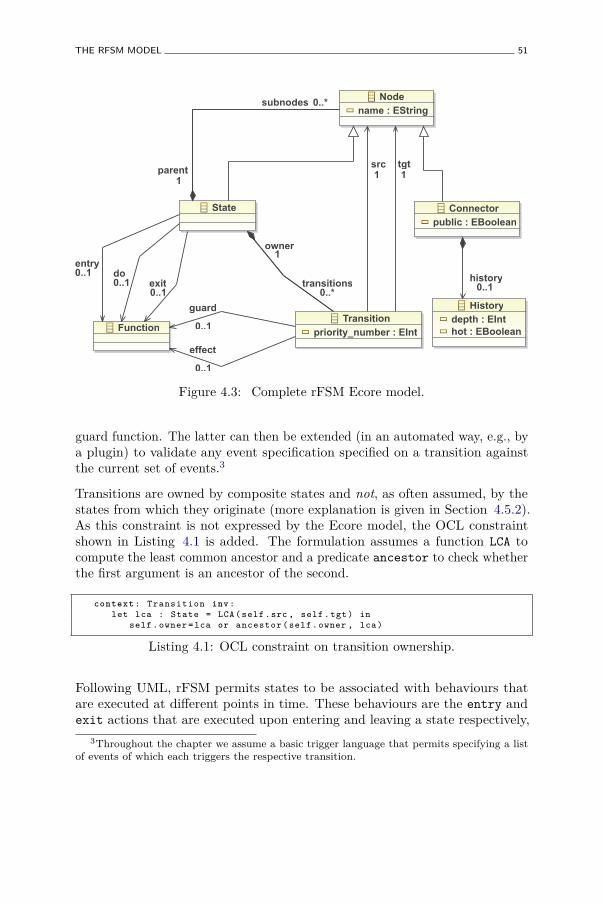
THE RFSM MODEL 51
Nodename : EString
State Connectorpublic : EBoolean
Transitionpriority_number : EIntFunction
Historydepth : EInthot : EBoolean
subnodes 0..*
parent1
transitions0..*
src1
tgt1
effect
0..1
guard
0..1
entry0..1 do
0..1 exit0..1
owner1
history0..1
Figure 4.3: Complete rFSM Ecore model.
guard function. The latter can then be extended (in an automated way, e.g., bya plugin) to validate any event specification specified on a transition againstthe current set of events.3
Transitions are owned by composite states and not, as often assumed, by thestates from which they originate (more explanation is given in Section 4.5.2).As this constraint is not expressed by the Ecore model, the OCL constraintshown in Listing 4.1 is added. The formulation assumes a function LCA tocompute the least common ancestor and a predicate ancestor to check whetherthe first argument is an ancestor of the second.
context : Transition inv:let lca : State = LCA(self.src , self.tgt) in
self. owner =lca or ancestor (self.owner , lca)
Listing 4.1: OCL constraint on transition ownership.
Following UML, rFSM permits states to be associated with behaviours thatare executed at different points in time. These behaviours are the entry andexit actions that are executed upon entering and leaving a state respectively,
3Throughout the chapter we assume a basic trigger language that permits specifying a listof events of which each triggers the respective transition.
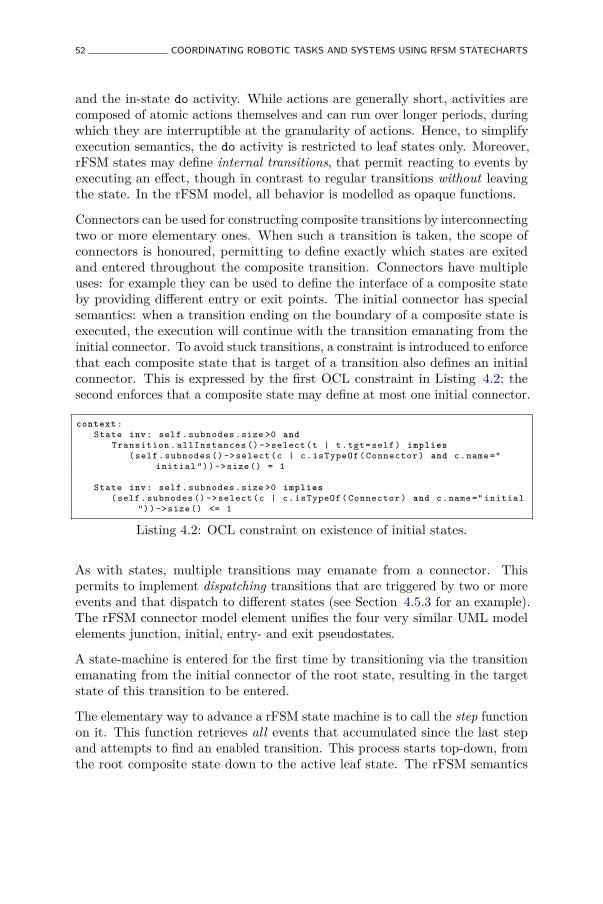
52 COORDINATING ROBOTIC TASKS AND SYSTEMS USING RFSM STATECHARTS
and the in-state do activity. While actions are generally short, activities arecomposed of atomic actions themselves and can run over longer periods, duringwhich they are interruptible at the granularity of actions. Hence, to simplifyexecution semantics, the do activity is restricted to leaf states only. Moreover,rFSM states may define internal transitions, that permit reacting to events byexecuting an effect, though in contrast to regular transitions without leavingthe state. In the rFSM model, all behavior is modelled as opaque functions.
Connectors can be used for constructing composite transitions by interconnectingtwo or more elementary ones. When such a transition is taken, the scope ofconnectors is honoured, permitting to define exactly which states are exitedand entered throughout the composite transition. Connectors have multipleuses: for example they can be used to define the interface of a composite stateby providing different entry or exit points. The initial connector has specialsemantics: when a transition ending on the boundary of a composite state isexecuted, the execution will continue with the transition emanating from theinitial connector. To avoid stuck transitions, a constraint is introduced to enforcethat each composite state that is target of a transition also defines an initialconnector. This is expressed by the first OCL constraint in Listing 4.2; thesecond enforces that a composite state may define at most one initial connector.
context :State inv: self. subnodes .size >0 and
Transition . allInstances () ->select (t | t.tgt=self) implies(self. subnodes () ->select (c | c. isTypeOf ( Connector ) and c.name ="
initial "))->size () = 1
State inv: self. subnodes .size >0 implies(self. subnodes () ->select (c | c. isTypeOf ( Connector ) and c.name =" initial
"))->size () <= 1
Listing 4.2: OCL constraint on existence of initial states.
As with states, multiple transitions may emanate from a connector. Thispermits to implement dispatching transitions that are triggered by two or moreevents and that dispatch to different states (see Section 4.5.3 for an example).The rFSM connector model element unifies the four very similar UML modelelements junction, initial, entry- and exit pseudostates.
A state-machine is entered for the first time by transitioning via the transitionemanating from the initial connector of the root state, resulting in the targetstate of this transition to be entered.
The elementary way to advance a rFSM state machine is to call the step functionon it. This function retrieves all events that accumulated since the last stepand attempts to find an enabled transition. This process starts top-down, fromthe root composite state down to the active leaf state. The rFSM semantics
THE RFSM MODEL 53
require that, as soon as an enabled transition is found, the searching terminatesand the transition is executed.
This approach of identifying the next transition has the advantage that itassigns explicit priorities to transitions, so-called structural priorities (Harel andNaamad 1996). The higher the source state of a transition is located in the statemachine’s tree, the higher the priority of the transition. The priority is visible inthe state graph: given a set of events, the current active states, and the value ofthe guard predicates, it is immediately visible which transition will be selected.This follows the approach chosen for the STATEMATE semantics. Furthermore,through structural priority conflicts between transitions are largely avoided,leaving only the possibility of local conflicts among transitions exiting the samestate. These conflicts can be eliminated either by additional guard conditions,or by a mechanism such as priority numbers
The minimum requirement for events is to carry identity and hence to becomparable between (possibly distributed) connected state machines. Thesimplest approach that remains comprehensible to humans and that is real-timesafe4 is to use string events.
The rFSM model does not include a parallel state element. The reason for thisis that this element requires making a large number of fundamental, platform-specific assumptions. These are, for instance, the order in which parallel statesare entered and exited, which underlying concurrency mechanisms such asthreads are being used to execute the state machine instances or what thepriorities of different parallel regions are. Instead of parallelism, a looselycoupled approach of distributed state machines is used, that permits multiplerFSM instances to interact by means of the available communication middleware(Sec. 4.8).
Moreover, rFSM does not adopt the STATEMATE execution time requirementwhich enforces that changes occurring in stepn can only be sensed in stepn+ 1,because of the complexity involved to manage such delayed processing of effectedchanges. But also, more importantly, because of the impossibility of delayingchanges in open environments, as it is inherently the case in robotics. rFSMalso differs with respect to the greediness property of transition selection, bychoosing a simpler take first approach to computing the set of transitions toexecute. In contrast to STATEMATE, external and internal events are notdistinguished.
The ability to simulate a statechart before execution is a useful feature thatcan facilitate early detection of errors. However, often subtle corner cases
4Obviously assuming that memory is appropriately pre-allocated for the longest possibleevent.

54 COORDINATING ROBOTIC TASKS AND SYSTEMS USING RFSM STATECHARTS
rootopening
do: open_gripper()
closingdo: closing_gripper()
graspingentry: enable_grasp_control()exit: disable_grasp_control()
e_tactile_lost / log("object dropped")
e_release
e_tactile [gripper_closed=false]
e_close
e_op
en
e_ta
ctile
[grip
per_
clos
ed=
true
]
Figure 4.4: Coordinating a gripper.
remain in which simulation and real system behaviour differ, as is the case forSTATEMATE. The rFSM reference implementation avoids this problem byunifying simulation and real system in form of an executable model. Obviously,this is possible only because the rFSM model targets the domain of coordination(in software) and need not be synthesised to targets such as VHDL (Very HighSpeed Integrated Circuit Hardware Description Language).
For convenience, we use the graphical notation of UML to visualise rFSMstatecharts throughout the chapter. The only deviation is necessary todistinguish between initial and non-initial connectors: the first are (as inUML) shown as filled circles while the latter are depicted as empty circles.Public connectors must be drawn on the border of composite states.
4.5 Structural Semantics
This Section discusses in detail the implications of different semantics of finitestate machine model elements. Since the rFSM model is derived from Harelstatecharts and UML state machines, the discussion is based upon thesestandards. Other models are included in the discussion where appropriate.
4.5.1 Fundamental State Machine Elements
The fundamental elements of UML state machines are introduced using anexample of a gripper coordination FSM shown in Figure 4.4. The requiredbehavior is the following. Initially the gripper shall be opened. After receivinga request e_close the gripper shall start to close. The closing will be abortedand the gripper reopened if the request e_open is received. If a successfull

STRUCTURAL SEMANTICS 55
grasp is detected, the grasp control loop shall be activated and remain activeuntil either the object is dropped (represented by e_tactile_lost) or releasingthe object is requested (e_release). If the grasp fails, the gripper shall bereopened in preparation of a new attempt.
The required behavior is realized as follows. Three states opening, closingand grasping are introduced, each representing a distinguishable and exclusivestate of the gripper. The filled circle is the initial pseudo-state and togetherwith the transition to opening ensures that the latter will be the first stateentered. Transitions connect states in a directed manner and carry a label ofthe following form:
trigger [guard condition] / transition effect
A trigger (typically one or more events) enables a transition between a sourceand a target state if and only if the optional guard condition evaluates to true.
An example of a guard condition can be found in Figure 4.4 on the transitionfrom state closing to grasping labelled with e_tactile [gripper_closed= false]. This expression defines a successful grasp as an event from thetactile sensor (e_tactile) and the condition that the gripper is not fully closed.Likewise, a failed grasp is detected by a tactile event and a fully closed gripper;this triggers the transition back to opening.
Guard conditions constrain transitions and often permit reducing the amountof states necessary. On the other hand, guards also hide state (hidden by notbeing represented by a state model element) and can thus lead to conflictingtransitions if two guards are simultaneously true. Therefore, it is considereda best practice to define these such that the exclusive disjunction of all guardconditions is true at any time.
A transition effect is an action that is executed during a transition betweenstates. In Figure 4.4 the transition triggered by event e_tactile_lost fromstate grasping to opening uses the effect for logging a message that thegrasped object has been dropped. Effects are necessary to define actions thatare specific to transitions and not to source or target states. For the graspingexample, the log message is only required when the transition to opening takesplace as a result of unintentionally dropping the grasped object (triggered bye_tactile_lost), and not when the object is deliberately released (e_release).
The Matlab Stateflow model (MathWorks ) includes a condition action, that isalready executed when the guard condition evaluates to true, but before thetransition as a whole is enabled. That way, condition actions behave similar

56 COORDINATING ROBOTIC TASKS AND SYSTEMS USING RFSM STATECHARTS
to transitions connected by UML Choice pseudo-states (describes in Section4.5.3), and are not included in the rFSM model for the same reason.
Actions can be associated with states too. The entry and exit actions areexecuted when a state is entered or exited respectively. For instance, whenthe state grasping is entered, force control is enabled and disabled when thestate is left. Like transition effects, entry and exit actions are always executedatomically as part of a transition and are never interrupted. In contrast, a state’sdo activity is executed as long as the state is active. In contrast to entry andexit actions, UML defines that (but not how!) the do activity can be interruptedif an event occurs that triggers an outgoing transition. For the example givenin Figure 4.4, in state closing the gripper motors are continuously stepped bythe closing_gripper() activity until the gripper is fully closed. Executingthis operation in the do-activity permits it to be interrupted by a request tore-open the gripper or an event from the tactile sensors.
It is important to note that for robotic coordination this interruptibility can notbe achieved by forced preemption, as for instance used to preempt operatingsystem threads. This is because in systems interacting with real hardware somecode paths must be treated as atomic in order to avoid non-deterministic andpotentially dangerous behaviour.
For achieving safe preemption of the do activity, rFSM adopts the idea ofGenoM codels (Fleury, Herrb, and Chatila 1997). A codel is the smallest non-interruptible unit of execution. Codels can be composed into larger computationsthat are interruptible at the granularity of the individual codel. By definingthe do activity in terms of codels, its execution can be safely interrupted. Theworst case latency for exiting the do program is defined by the execution time ofthe longest codel. The rFSM reference implementation realises this behaviourby implementing do using coroutines (Conway 1963).
The last fundamental primitive is the internal transition. The behaviour of thistransition type is best explained by contrasting it to a self-transition, which isa regular transition starting and ending on the same state. When the lattertransitions, the state is exited and entered, including invocation of the respectiveexit and entry actions. In contrast, when an internal transition is taken, thedefining state is not exited. Consequently, the only action invoked is the internaltransitions effect. Syntactically, internal transitions are drawn within a stateand otherwise have the same formtrigger [guard] / effect as regular ones.
Interestingly, this seemingly simple model element already illustrates the issue ofimplicit semantic variation points in UML. For instance, it is undefined whether,in case of conflicts, internal or external transitions take priority. Furthermore,

STRUCTURAL SEMANTICS 57
it is unclear if and how an internal transition affects a running do activity.Does it cause the do activity to restart or does the internal transition effect runinterleaved?
According to Simons (Simons 2000), internal transitions are redundant sinceall behaviour associated with a state can be modelled using a substate. This ishowever, only true for an internal transition defined within a leaf-state. Internaltransitions defined within non-leaf composite states can not be converted toself-transitions, since the execution of the effect action implies exiting andentering of all child states. In practice, a typical use-case for internal transitionsis to model secondary mode switches. For the grasping FSM of Figure 4.4, thiscould be to permit runtime switching between different controller configurations,but without otherwise interfering with the nominal grasping task. Such modeswitches can be conveniently modelled using internal transitions defined at theroot level.
With respect to variation points, the rFSM model assumes the following:regarding priorities, internal transitions are given equal priority to externalones unless made explicit by priority numbers. As to interference with thedo activity, it is assumed that the internal transition execution takes placeinterleaved, though in a safe way honouring the atomicity of codels.
In summary, the rFSM model adopts the following fundamental state machineelements from the UML2 standard: state, transition, internal transitions, event,entry, exit and transition effect actions, do activity and guard condition.
4.5.2 Hierarchical State Machines
Hierarchical state machines were first introduced by Harel (Harel 1987). Thekey idea is to permit nesting of states within states. This is illustrated byFigure 4.5 showing a model of a robot performing a force-controlled operationon a work piece. The actual operation is modelled using a nested state machinewithin the operational state. Such a state machine containing other statesis also called a composite state, since it can be understood as the compositionof multiple state machines. When the operational state is entered via thetransition triggered by e_range_clear, it immediately continues entering theapproaching state, since this is connected from the initial connector. As aconsequence the work piece is approached until the event e_contact is received,that triggers the transition to the in_contact state, in which force control isenabled.
At the top level, the two states safe_mode and operational describe the basicbehaviour of the system. The safe_mode state stops the robot immediately
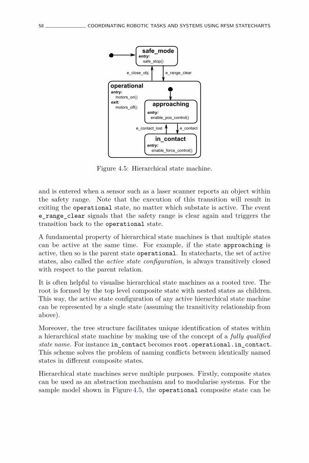
58 COORDINATING ROBOTIC TASKS AND SYSTEMS USING RFSM STATECHARTS
safe_modeentry: safe_stop()
operational
in_contactentry: enable_force_control()
e_close_obj e_range_clear
e_contact_lost e_contact
approachingentry: enable_pos_control()
entry: motors_on()exit: motors_off()
Figure 4.5: Hierarchical state machine.
and is entered when a sensor such as a laser scanner reports an object withinthe safety range. Note that the execution of this transition will result inexiting the operational state, no matter which substate is active. The evente_range_clear signals that the safety range is clear again and triggers thetransition back to the operational state.
A fundamental property of hierarchical state machines is that multiple statescan be active at the same time. For example, if the state approaching isactive, then so is the parent state operational. In statecharts, the set of activestates, also called the active state configuration, is always transitively closedwith respect to the parent relation.
It is often helpful to visualise hierarchical state machines as a rooted tree. Theroot is formed by the top level composite state with nested states as children.This way, the active state configuration of any active hierarchical state machinecan be represented by a single state (assuming the transitivity relationship fromabove).
Moreover, the tree structure facilitates unique identification of states withina hierarchical state machine by making use of the concept of a fully qualifiedstate name. For instance in_contact becomes root.operational.in_contact.This scheme solves the problem of naming conflicts between identically namedstates in different composite states.
Hierarchical state machines serve multiple purposes. Firstly, composite statescan be used as an abstraction mechanism and to modularise systems. For thesample model shown in Figure 4.5, the operational composite state can be
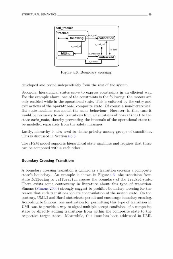
STRUCTURAL SEMANTICS 59
tracked
following
hitting
calibration
untracked
e_cmd_cali
e_untracked
e_done
e_tracked
e_cmd_hit
e_cmd_cali
ball_tracker
Figure 4.6: Boundary crossing.
developed and tested independently from the rest of the system.
Secondly, hierarchical states serve to express constraints in an efficient way.For the example above, one of the constraints is the following: the motors areonly enabled while in the operational state. This is enforced by the entry andexit actions of the operational composite state. Of course a non-hierarchicalflat state machine can model the same behaviour. However, in that case itwould be necessary to add transitions from all substates of operational to thestate safe_mode, thereby preventing the internals of the operational state tobe modelled separately from the safety measures.
Lastly, hierarchy is also used to define priority among groups of transitions.This is discussed in Section 4.6.3.
The rFSM model supports hierarchical state machines and requires that thesecan be composed within each other.
Boundary Crossing Transitions
A boundary crossing transition is defined as a transition crossing a compositestate’s boundary. An example is shown in Figure 4.6: the transition fromstate following to calibration crosses the boundary of the tracked state.There exists some controversy in literature about this type of transition.Simons (Simons 2000) strongly suggest to prohibit boundary crossing for thereason that such transitions violate encapsulation of the nested state. On thecontrary, UML2 and Harel statecharts permit and encourage boundary crossing.According to Simons, one motivation for permitting this type of transition inUML was to provide a way to signal multiple accept conditions of a compositestate by directly adding transitions from within the composite state to therespective target states. Meanwhile, this issue has been addressed in UML
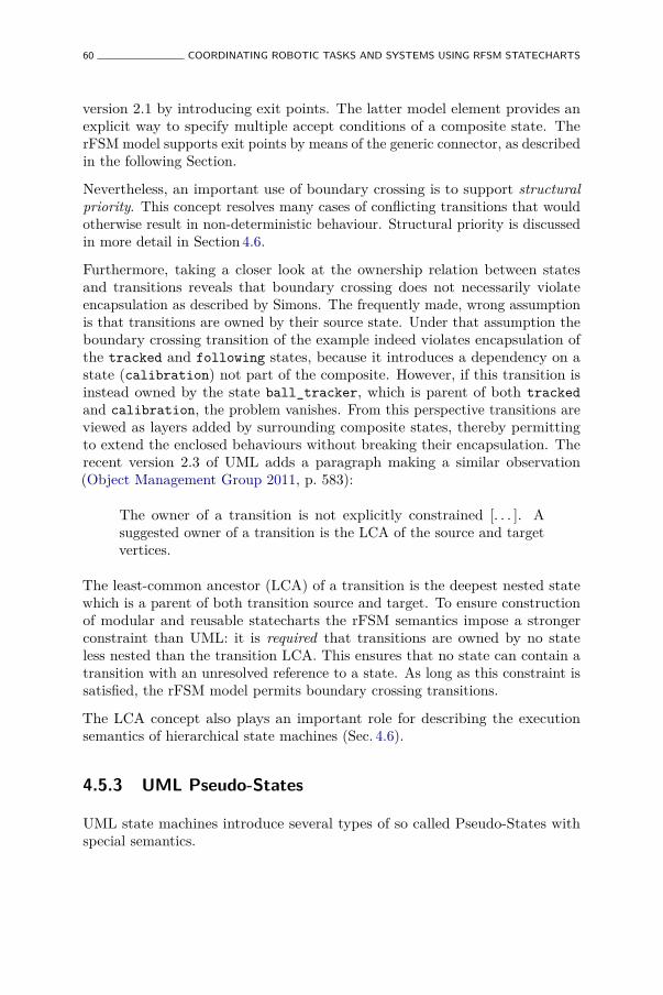
60 COORDINATING ROBOTIC TASKS AND SYSTEMS USING RFSM STATECHARTS
version 2.1 by introducing exit points. The latter model element provides anexplicit way to specify multiple accept conditions of a composite state. TherFSM model supports exit points by means of the generic connector, as describedin the following Section.
Nevertheless, an important use of boundary crossing is to support structuralpriority. This concept resolves many cases of conflicting transitions that wouldotherwise result in non-deterministic behaviour. Structural priority is discussedin more detail in Section 4.6.
Furthermore, taking a closer look at the ownership relation between statesand transitions reveals that boundary crossing does not necessarily violateencapsulation as described by Simons. The frequently made, wrong assumptionis that transitions are owned by their source state. Under that assumption theboundary crossing transition of the example indeed violates encapsulation ofthe tracked and following states, because it introduces a dependency on astate (calibration) not part of the composite. However, if this transition isinstead owned by the state ball_tracker, which is parent of both trackedand calibration, the problem vanishes. From this perspective transitions areviewed as layers added by surrounding composite states, thereby permittingto extend the enclosed behaviours without breaking their encapsulation. Therecent version 2.3 of UML adds a paragraph making a similar observation(Object Management Group 2011, p. 583):
The owner of a transition is not explicitly constrained [. . . ]. Asuggested owner of a transition is the LCA of the source and targetvertices.
The least-common ancestor (LCA) of a transition is the deepest nested statewhich is a parent of both transition source and target. To ensure constructionof modular and reusable statecharts the rFSM semantics impose a strongerconstraint than UML: it is required that transitions are owned by no stateless nested than the transition LCA. This ensures that no state can contain atransition with an unresolved reference to a state. As long as this constraint issatisfied, the rFSM model permits boundary crossing transitions.
The LCA concept also plays an important role for describing the executionsemantics of hierarchical state machines (Sec. 4.6).
4.5.3 UML Pseudo-States
UML state machines introduce several types of so called Pseudo-States withspecial semantics.
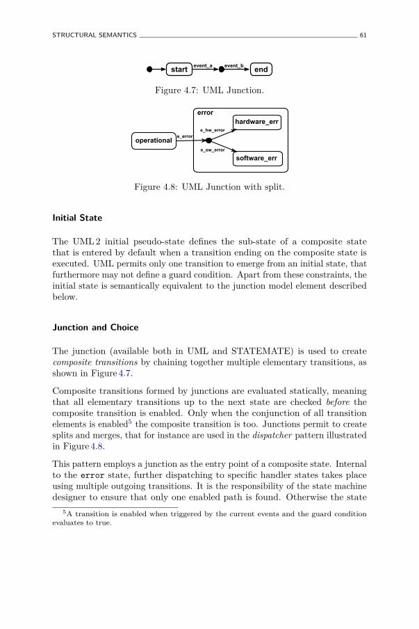
STRUCTURAL SEMANTICS 61
start endevent_a
Figure 4.7: UML Junction.
operational
error
e_error
e_sw_error
e_hw_error
hardware_err
software_err
Figure 4.8: UML Junction with split.
Initial State
The UML2 initial pseudo-state defines the sub-state of a composite statethat is entered by default when a transition ending on the composite state isexecuted. UML permits only one transition to emerge from an initial state, thatfurthermore may not define a guard condition. Apart from these constraints, theinitial state is semantically equivalent to the junction model element describedbelow.
Junction and Choice
The junction (available both in UML and STATEMATE) is used to createcomposite transitions by chaining together multiple elementary transitions, asshown in Figure 4.7.
Composite transitions formed by junctions are evaluated statically, meaningthat all elementary transitions up to the next state are checked before thecomposite transition is enabled. Only when the conjunction of all transitionelements is enabled5 the composite transition is too. Junctions permit to createsplits and merges, that for instance are used in the dispatcher pattern illustratedin Figure 4.8.
This pattern employs a junction as the entry point of a composite state. Internalto the error state, further dispatching to specific handler states takes placeusing multiple outgoing transitions. It is the responsibility of the state machinedesigner to ensure that only one enabled path is found. Otherwise the state
5A transition is enabled when triggered by the current events and the guard conditionevaluates to true.
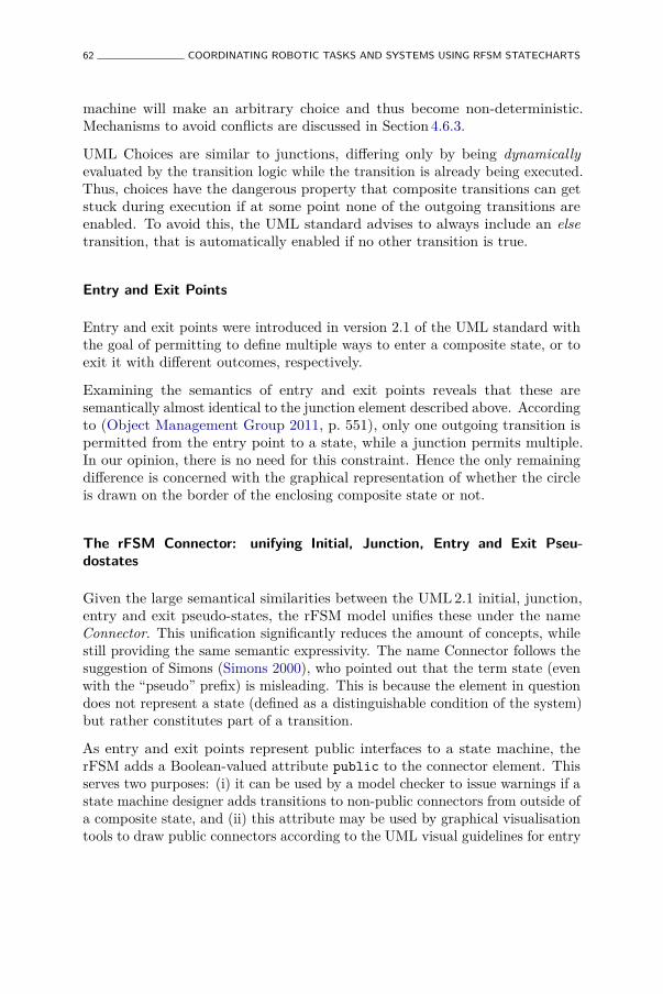
62 COORDINATING ROBOTIC TASKS AND SYSTEMS USING RFSM STATECHARTS
machine will make an arbitrary choice and thus become non-deterministic.Mechanisms to avoid conflicts are discussed in Section 4.6.3.
UML Choices are similar to junctions, differing only by being dynamicallyevaluated by the transition logic while the transition is already being executed.Thus, choices have the dangerous property that composite transitions can getstuck during execution if at some point none of the outgoing transitions areenabled. To avoid this, the UML standard advises to always include an elsetransition, that is automatically enabled if no other transition is true.
Entry and Exit Points
Entry and exit points were introduced in version 2.1 of the UML standard withthe goal of permitting to define multiple ways to enter a composite state, or toexit it with different outcomes, respectively.
Examining the semantics of entry and exit points reveals that these aresemantically almost identical to the junction element described above. Accordingto (Object Management Group 2011, p. 551), only one outgoing transition ispermitted from the entry point to a state, while a junction permits multiple.In our opinion, there is no need for this constraint. Hence the only remainingdifference is concerned with the graphical representation of whether the circleis drawn on the border of the enclosing composite state or not.
The rFSM Connector: unifying Initial, Junction, Entry and Exit Pseu-dostates
Given the large semantical similarities between the UML2.1 initial, junction,entry and exit pseudo-states, the rFSM model unifies these under the nameConnector. This unification significantly reduces the amount of concepts, whilestill providing the same semantic expressivity. The name Connector follows thesuggestion of Simons (Simons 2000), who pointed out that the term state (evenwith the “pseudo” prefix) is misleading. This is because the element in questiondoes not represent a state (defined as a distinguishable condition of the system)but rather constitutes part of a transition.
As entry and exit points represent public interfaces to a state machine, therFSM adds a Boolean-valued attribute public to the connector element. Thisserves two purposes: (i) it can be used by a model checker to issue warnings if astate machine designer adds transitions to non-public connectors from outside ofa composite state, and (ii) this attribute may be used by graphical visualisationtools to draw public connectors according to the UML visual guidelines for entry

STRUCTURAL SEMANTICS 63
and exit points, which is on the border of a composite state. In the following werepresent connectors as small circles: initial connectors are filled in black whileall others are not filled. This avoids the ambiguity in UML resulting from bothinitial and junction pseudo-states being graphically depicted as black, filledcircles. If this notation were used instead of UML, the middle junction in UMLdiagram4.7 (connecting start with end would be not filled, since it is not aninitial connector. The junction in diagram4.8 would move to the border oferror state and be likewise not filled, unless it actually is the initial state.
Because of the dangerous property of permitting stuck transitions, the UMLchoice pseudo-states is not included in the rFSM model.
Final State
Transitioning to a UML final state means that the enclosing state has completed.In contrast to the initial pseudo-state, the final state is not a pseudo-state atall, but a specialised regular state. The reason for this is not explained in thestandard, however it can be assumed that this is because a well-formed UMLstate machine can actually be in the final state. In contrast, it is not possibleto be in the initial state, since this is part of a transition. When a final stateis entered, UML requires a completion event to be raised that may triggertransitions emanating from a parent state. If no transitions are enabled, thefinal state remains active.
The rFSM model does not introduce a special final state. Instead an empty,user-defined regular state named final can serve this purpose. When no dofunction is defined, the completion event is raised immediately after entry andcan hence be used to trigger transitions emanating from parent states.
Major semantic differences exist between UML and rFSM with respect to thecompletion event itself; this is discussed in Section 4.7.4.
Terminate
The UML Terminate pseudo-state offers a mechanism to terminate the executionof the entire state machine instance by transitioning to this connector. Noactions are executed except those associated with the transition. In our opinion,there is no benefit of using a Terminate model element instead of a regular statecalled terminate that executes the required shutdown procedure. Hence therFSM model does not include a terminate pseudo-state.
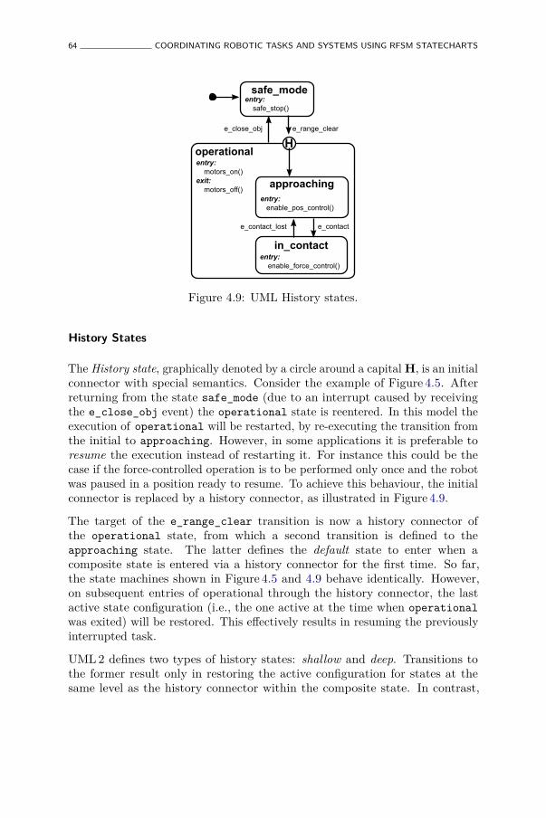
64 COORDINATING ROBOTIC TASKS AND SYSTEMS USING RFSM STATECHARTS
safe_modeentry: safe_stop()
operational
in_contactentry: enable_force_control()
e_close_obj e_range_clear
e_contact_lost e_contact
approachingentry: enable_pos_control()
entry: motors_on()exit: motors_off()
Figure 4.9: UML History states.
History States
The History state, graphically denoted by a circle around a capitalH, is an initialconnector with special semantics. Consider the example of Figure 4.5. Afterreturning from the state safe_mode (due to an interrupt caused by receivingthe e_close_obj event) the operational state is reentered. In this model theexecution of operational will be restarted, by re-executing the transition fromthe initial to approaching. However, in some applications it is preferable toresume the execution instead of restarting it. For instance this could be thecase if the force-controlled operation is to be performed only once and the robotwas paused in a position ready to resume. To achieve this behaviour, the initialconnector is replaced by a history connector, as illustrated in Figure 4.9.
The target of the e_range_clear transition is now a history connector ofthe operational state, from which a second transition is defined to theapproaching state. The latter defines the default state to enter when acomposite state is entered via a history connector for the first time. So far,the state machines shown in Figure 4.5 and 4.9 behave identically. However,on subsequent entries of operational through the history connector, the lastactive state configuration (i.e., the one active at the time when operationalwas exited) will be restored. This effectively results in resuming the previouslyinterrupted task.
UML2 defines two types of history states: shallow and deep. Transitions tothe former result only in restoring the active configuration for states at thesame level as the history connector within the composite state. In contrast,
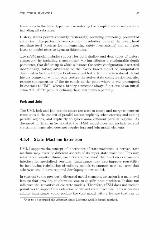
STRUCTURAL SEMANTICS 65
transitions to the latter type result in restoring the complete state configurationincluding all substates.
History states permit (possibly recursively) resuming previously preemptedactivities. This pattern is very common in robotics, both at the lower, hardreal-time level (such as for implementing safety mechanisms) and at higherlevels to model reactive agent architectures.
The rFSM model includes support for both shallow and deep types of historyconnectors by including a generalised version offering a configurable depthparameter, that defines up to which substates the active configuration is restored.Additionally, taking advantage of the Codel based model of computationdescribed in Section 4.5.1, a Boolean-valued hot attribute is introduced. A hothistory connector will not only restore the active state configuration but alsoresume the execution of the do codels at the point where it was preempted.In contrast to UML, where a history connector always functions as an initialconnector, rFSM permits defining these attributes separately.
Fork and Join
The UML fork and join pseudo-states are used to create and merge concurrenttransitions in the context of parallel states: implicitly when entering and exitingparallel regions, and explicitly to synchronise different parallel regions. Asdiscussed in detail in Section 4.8, the rFSM model does not include parallelstates, and hence also does not require fork and join model elements.
4.5.4 State Machine Extension
UML2 supports the concept of inheritance of state machines. A derived statemachine may override different aspects of its super state machine. This way,inheritance permits defining abstract state machines6 that function as a commoninterface for specialised versions. Inheritance may also improve reusabilityby facilitating redefinition of existing models to support new use-cases thatotherwise would have required developing a new model.
In contrast to the previously discussed model elements, extension is a meta-levelfeature that provides an alternate way to specify state machines. It does notinfluence the semantics of concrete models. Therefore, rFSM does not includeprimitives to support the definition of derived state machines. This is becauseadding inheritance would pollute the core model with a feature that can be
6Not to be confused the Abstract State Machine (ASM) formal method.
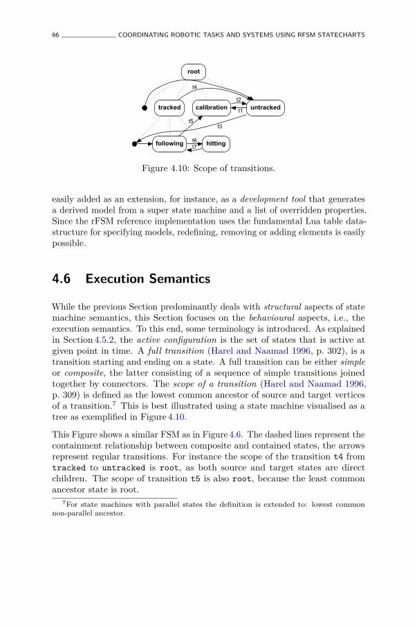
66 COORDINATING ROBOTIC TASKS AND SYSTEMS USING RFSM STATECHARTS
root
tracked calibration untracked
following hitting
t4
t6
t5
t7
t2
t3
t1
Figure 4.10: Scope of transitions.
easily added as an extension, for instance, as a development tool that generatesa derived model from a super state machine and a list of overridden properties.Since the rFSM reference implementation uses the fundamental Lua table data-structure for specifying models, redefining, removing or adding elements is easilypossible.
4.6 Execution Semantics
While the previous Section predominantly deals with structural aspects of statemachine semantics, this Section focuses on the behavioural aspects, i.e., theexecution semantics. To this end, some terminology is introduced. As explainedin Section 4.5.2, the active configuration is the set of states that is active atgiven point in time. A full transition (Harel and Naamad 1996, p. 302), is atransition starting and ending on a state. A full transition can be either simpleor composite, the latter consisting of a sequence of simple transitions joinedtogether by connectors. The scope of a transition (Harel and Naamad 1996,p. 309) is defined as the lowest common ancestor of source and target verticesof a transition.7 This is best illustrated using a state machine visualised as atree as exemplified in Figure 4.10.
This Figure shows a similar FSM as in Figure 4.6. The dashed lines represent thecontainment relationship between composite and contained states, the arrowsrepresent regular transitions. For instance the scope of the transition t4 fromtracked to untracked is root, as both source and target states are directchildren. The scope of transition t5 is also root, because the least commonancestor state is root.
7For state machines with parallel states the definition is extended to: lowest commonnon-parallel ancestor.

EXECUTION SEMANTICS 67
The scope of a transition is essential for statechart execution semantics becauseit determines how the active configuration changes when a transition is taken.
4.6.1 Fundamental Execution Semantics
The basic mode of operation of a state machine is to transition in response toevents received. UML2 describes the run-to-completion assumption that definesthat a new event will only be processed after the processing of the current onehas completed. This conforms to the STATEMATE semantics that requirethe following: "Reactions to external and internal events [. . . ] can be sensedonly after completion of the step" (Harel and Naamad 1996, p. 298). For bothsemantics, this implies that in order to react to new events, the state machinemust be in a stable state; a stable state being defined as the execution of exitaction, transition effect and entry action having completed.8
Beside these similarities, major differences exist with respect to how andwhich events are selected for computing a transition, how conflicts betweensimultaneously enabled transitions are avoided or resolved, and what thesemantics of events are.
4.6.2 Event Selection
In UML2 events are stored in a global queue from which they are removedone at a time. The standard does not specify the exact procedure (ObjectManagement Group 2011, p. 574), in order to permit modeling of differentpriority-based schemes. After an event has been selected, it is used to computethe set of enabled transitions. If none are triggered, the event is discarded.
The classical statechart semantics differ from this by taking all events thatoccurred since the last transition into account for computing the set of enabledtransitions. These events are discarded after the step.
4.6.3 Computing the Enabled Transition Set
Next, the selected event(s) are used to compute the set of enabled transitionsgiven all transitions emanating from the current active configuration. Withboth UML and Harel semantics it is possible that the set of enabled transitions
8It is theoretically impossible to encounter a STATEMATE statechart during transition,since transitions are assumed to take zero time. This is the so-called perfect synchronicityhypothesis, which seldom holds in modern robotic systems.
68 COORDINATING ROBOTIC TASKS AND SYSTEMS USING RFSM STATECHARTS
contains more than one transition. Apart from certain special cases,9 thiscondition signifies a conflict: executing both transitions would result in aninvalid configuration of the state machine as multiple non-parallel states wouldbecome active simultaneously.
Because conflicts are likely to happen, it is necessary to resolve these by applyingrules. The concept of structural priority, introduced by Harel (Harel and Naamad1996, p. 328) largely resolves conflicts by assigning priorities to transitions basedon their location in the state machine tree. The initial approach was to assignhigher priorities the higher the position of the transition LCA was in thehierarchy of states. Later versions of STATEMATE simplified this by usingthe transition source state instead of the LCA. This priority rule solves mostconflicts; the remaining can be explicitly solved by assigning so-called prioritynumbers to transitions or by using a domain specific mechanism realized as aguard condition.
UML state machines adopt Harel’s approach of structural priority although theorder of priorities is reversed. This means that transitions with deeper nestedsource states are assigned higher priority than less nested states. The reasonfor this deviation is not explained in the UML standard but presumably has itscause in the inherent object oriented focus of UML. Assigning higher priorityto deeper nested states permits substates to be interpreted as specialisationsthat refine the behaviour of parent states.
4.6.4 Discussion
The different focus of UML state machines and Harel statecharts becomeapparent by examining both execution semantics. The UML semantics, beingpart of an Object Oriented modeling standard are more focused on introducingobject oriented concepts in state machines. In contrast, the original Harelsemantics are targeted towards building complex, reactive systems. Hence, itcomes as no surprise that the classical STATEMATE semantics are often bettersuited to model complex, multi-robot systems.
The rFSM model adopts the classical statechart semantics of both event selectionand computation of the enabled event set, because of the reasons discussedbelow.
Firstly, the behaviour of a classical statechart is largely predictable from thegraphical model since the next transition to be executed depends only on theactive configuration, the set of input events and the state of the guard conditions.
9Multiple transitions entering a parallel state are simultaneously enabled without being inconflict.
EXECUTION SEMANTICS 69
This supports developers that can rely on the graphical model to understandand predict the statechart behaviour. This is not as simple for an UML model,that requires a developer to have additional knowledge about the particulardequeuing implementation and about the currently deferred events (discussedin Section 4.7.7).
Secondly, taking all events into account for determining which transitions toexecute has the advantage that the highest-priority events take effect whilelower-priority events are ignored. Moreover, the queue of events is less likely tooverflow by being emptied on each step. This is important for complex systemsfor which floods of events are possible.
Thirdly, the classical statechart approach of conflict resolution supportscompositional robustness. The example in Figure 4.5 illustrates this. Forinstance, assume the developer of the nested state machine in_contact adds aself-transition for the event e_close_obj. This transition conflicts with the top-level transition from operational to safe_mode. In the Harel semantics thisdoes not affect the behaviour of the state machine as a whole, since the (safetyrelevant) transition from operational to safe_mode has higher structuralpriority. The system is said to behave compositionally robust to a minor change(minor being defined in terms of depth of the changed state) because a smallchange results in little or no change of the system as a whole. However, in theUML semantics this change will alter the behaviour of the entire state machinebecause the new transition will take precedence and prevent transitioning tosafe_mode. Hence a minor local change results in a large change at systemlevel. For modeling complex and modular systems this is undesirable.
rFSM follows the STATEMATE approach of using the transition source depthto define priorities. Furthermore, the mechanism of priority numbers is adoptedto resolve conflicts among transitions emanating from a single state.
4.6.5 Evaluating Composite Transitions
One important issue that is scarcely discussed for UML and STATEMATEsemantics is the extent to which composite transitions are checked prior tobeing executed. Starting from the example shown in Figure 4.5 and assumingthat safe_mode is active and the event e_range_clear is in the queue, thetransition from safe_mode to operational is enabled. The question posed bythis scenario is whether the state machine logic may already start executingthe transition at this point, or if further checking is necessary. The imminentdanger of starting execution is that after the first part of the transition has beenexecuted, the second part from the initial connector to the approaching stateis not enabled, hence resulting in the FSM getting stuck. UML2.1 circumvents

70 COORDINATING ROBOTIC TASKS AND SYSTEMS USING RFSM STATECHARTS
this problem by prohibiting initial transitions to define guard conditions, andby introducing a semantic variation point (Object Management Group 2011,p. 560). The latter leaves open how to interpret transitions to composite stateswithout initial connectors. It is then up to tool-implementers to decide if thisis to be treated as an ill-formed state machine or as the intention to enter acomposite state but none of its substates.
Regarding this issue, there are differences in STATEMATE between simulatedand generated code (Harel and Naamad 1996, p. 303): while the simulator willnot begin executing the transition, the generated code will, and hence get stuckwhen the continuation transition is not enabled.
The rFSM model deals with the above-mentioned UML variation point bydefining a transition to a composite state without an initial connector as ill-formed. Secondly, deep transition checking is required, meaning that for atransition to be enabled the complete path until reaching a leaf state mustbe enabled, thus including zero to many transitions from initial connectorsto states. This eliminates the possibility of transitions getting stuck duringexecution. Because the rFSM model treats initial connectors and junctionsidentically, no special logic is required. Moreover, the UML constraint thatforbids initial transitions to define guard conditions becomes unnecessary andcan be dropped.
4.6.6 Transition Execution
Once a transition is enabled, it is executed in the following sequence. Firstly,all source states up to, but excluding, the LCA are exited by invoking their exitfunctions. For each composite state of these states, the last active sub-stateis stored in preparation of a potential re-entry via a history connector. Asan example, for a transition between two states within the same compositestate only the source state is exited, as the LCA is the composite state. Incontrast, for transitions contained by different composite states, multiple statesare exited.
Secondly, the transition effect is executed, followed by the third part of thetransition execution in which the transition target state including its parentstates are entered. If this target is a leaf state, the transition execution iscompleted. Otherwise, the transition execution is continued at the initialconnector of the composite state until a leaf state is reached. In case ofcomposite transitions this procedure is executed for each individual transition.
As an example, assume that the active state of the statechart in Figure 4.6is following, and the event e_cmd_cali occurs. The LCA of this transition
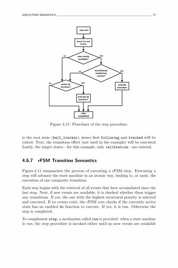
EXECUTION SEMANTICS 71
step start
check for newevents
new eventsavailable?
no yes
transition(s)enabled by
events?
executetransition
yesno
active dofunction?
execute dofunction?
stepcompleted
yesno
Figure 4.11: Flowchart of the step procedure.
is the root state (ball_tracker), hence first following and tracked will beexited. Next, the transition effect (not used in the example) will be executed.Lastly, the target states—for this example, only calibration—are entered.
4.6.7 rFSM Transition Semantics
Figure 4.11 summarises the process of executing a rFSM step. Executing astep will advance the state machine in an atomic way, leading to, at most, theexecution of one composite transition.
Each step begins with the retrieval of all events that have accumulated since thelast step. Next, if new events are available, it is checked whether these triggerany transitions. If yes, the one with the highest structural priority is selectedand executed. If no events exist, the rFSM core checks if the currently activestate has an enabled do function to execute. If yes, it is run. Otherwise thestep is completed.
To complement step, a mechanism called run is provided: when a state machineis run, the step procedure is invoked either until no new events are available
72 COORDINATING ROBOTIC TASKS AND SYSTEMS USING RFSM STATECHARTS
and the active state has no enabled do function, or a maximum number of steps(given as an argument to run) have been executed. The practical application ofstep and run is described in detail in Section 4.10.
An active do function can be configured to be in one of two modes: idle andnon-idle. Which one is appropriate is strongly influenced by the model of statemachine progression (Sec. 4.10.1). If a do function is non-idle, the state machineengine will recall it immediately, provided that no events enabling outgoingtransitions were received. This permits using the do function to carry outa computation as fast as possible while at the same time remaining reactiveto incoming events. On the other hand, an idle do function is not recalledimmediately, but only upon the next step invocation. This mode is usuallyappropriate when the do function is to be used to periodically carry out anaction while the current state is active.
4.7 Event Semantics
Previous Sections described how events enable transitions and what are theramifications thereof. This Section examines the semantics of events themselves,their structure and specialisations.
In classical statecharts, such as the STATEMATE semantics, events can beunderstood as messages which represent the occurrence of something. Eventscan be compared to events specified on transitions and are hence required tohave identity. UML includes this basic event type using the name SignalEvent.However, there exist other, more specialised types of events which are discussedbelow.
4.7.1 UML ChangeEvent
A ChangeEvent is raised when a Boolean-valued condition evaluates to true. Forthis, the syntax when <condition> on a transition is used. In principle, suchan event type seems useful for robotics coordination. The problem however, isthat the UML specification leaves open when and how the condition is evaluated(Object Management Group 2011, p. 452). Obviously, for a hard real-timerobotic system this is not acceptable, as the condition checking will directlyinfluence the worst-case latency of the event generation and hence the transitionexecution. This situation can be remedied in two ways. Either the ChangeEventis extended to take into account the additional semantics of evaluation frequency,timing precision etc., or this event type is excluded from the core semantics
EVENT SEMANTICS 73
and realized outside of the statechart. In the latter approach the validationis carried out by a separate component that raises the respective events. ForrFSM the latter approach was chosen, as it does not require extensions to thecore semantics and makes the involved assumptions explicit. Moreover, manycomputational components such as robot driver components, control componentsor estimators can easily provide such validation of internal conditions and therespective event generation with little computational overhead. Therefore, it isconsidered a best practice to extend computational components to raise eventsbased on configurable constraints on their internal state.
4.7.2 UML Time Event
UML defines a TimeEvent as an event which is raised at a relative or absolutepoint in time. The syntax used is after <duration> or at <time>. For roboticapplications TimeEvents can be useful in various circumstances, yet they sufferfrom a similar limitation as ChangeEvents, as no assumptions can be madeon the qualitative properties of the time used. Hence, the variation point canbe resolved likewise, by either extending the TimeEvent or by implementingit outside of the scope of the core semantics. rFSM takes the latter approachand does not include TimeEvents in the core semantics. Instead, TimeEventsare realized as a plugin that must be explicitely configured with a source oftime. This way, the state machine developer is forced to consciously select atime source that provides the necessary quality of service.
It is worth pointing out the danger of misusing time events for modeling flowchart-like execution flow (Simons 2000). A state should reflect a distinguishedcondition of the system or a part thereof, not a time-bounded computation.The need for the latter is an indication to use a Flowchart formalism such asUML Activity Diagrams. Conversely, TimeEvents have important use-cases,most notably to model timeouts that trigger transitions to states for dealingwith the absence of the nominally expected event.
4.7.3 UML Call Event
A CallEvent is an event defined for state machines used in the context of ObjectOriented software systems. This event represents a request to invoke a certainmethod on an object. The CallEvent is generated after the operation has beeninvoked, thereby permitting the FSM to track the methods that are invoked.As the rFSM semantics do not make any assumptions about the underlyingprogramming paradigm, no CallEvent is included.
74 COORDINATING ROBOTIC TASKS AND SYSTEMS USING RFSM STATECHARTS
4.7.4 UML Completion Event and Final State
According to UML, a completion event is raised either when the do behaviourof a simple state completes or a final state is entered. Graphically it is depictedby an unlabelled transition (called completion transition) emanating from asimple state or from a composite state that contains a final state.
The UML completion event has special semantics and is implicitly assignedhighest priority among all events. For the UML semantics this is necessary, as aCompletionEvent does not carry any information about which state completed.Therefore, this event is only valid for the active configuration of the FSM at itstime of generation. Queuing a completion event would permit the triggeringof different unlabelled completion transitions from other states at a later time,which would be undesirable.
The rFSM model avoids this problem by adding identity in form of thefully qualified state name (Sec. 4.5.2) to the completion event. For instance,the completion event of the in_contact state of Figure 4.5 would [email protected]_contact. This way no special treatment ofthe completion event is necessary. Moreover, by not assigning special priorityto this event, priorities are respected as a completion event must compete withall other events stored in the event queue. Finally, the readability of completiontransitions is improved by labelling these explicitly. The semantics of unlabelledtransitions are discussed below.
As in UML, the rFSM model requires that the completion event is raised eitherwhen the do function of a leaf state has completed, or immediately if no dois defined. The use-case of UML final states is covered in rFSM by using anempty, regular leaf state named final. Once this state is entered, the completionevent e_done@final will be raised. Transitions can then be defined to react tothis event.
4.7.5 UML AnyReceiveEvent and unlabeled Transitions
As the rFSM model (unlike UML) chooses to label completion transitionsexplicitly, the question of the semantics of unlabelled transition arises. Thereexist at least two natural interpretations of such a transition. The first is atransition that is never enabled, because no events are specified that could triggerit. The second, more useful interpretation is a transition that is enabled by anyevent. Harel statecharts opt for this interpretation because such true-transitionscan be useful: when chaining multiple transitions by means of Connectors, true-transitions permit to avoid repeating the enumeration of the events specified
EVENT SEMANTICS 75
on the previous transitions for all subsequent transitions, thereby reducingredundancy. A second use-case is to avoid having to exhaustively enumerate allpossible events for a transition that is only constrained by a guard condition.For UML state machines this interpretation can be realised by specifying theAnyReceiveEvent which is denoted by the keyword any. Because simpler andarguably more intuitive, the rFSM model adopts the Harel interpretation ofthe unlabelled transition as a transition being triggered by any event.
4.7.6 Edge- and Level-triggered Events
In the simplest case, an event represents the one-time occurrence of something.Based on all events that occurred since the last step, the FSM core reasons tofind and execute a transition and afterwards drops these events. However, insome cases events are not only valid at a particular time instant, but persistduring a period of time and/or until some action takes place. These two typesof events are called edge and level triggered events, respectively.10 The first areonly valid at one point in time (on the rising or falling edge) while the secondpersist for some time, i.e., as long as the level remains high.
Level triggered events are often useful to signal a condition requiring some formof response. For example this could be a slight over-temperature condition ofa motor during a manipulation task. Eventually, it is necessary to react tothis event and reduce the overall speed, however this can take place after thecurrent manipulation has completed. Moreoever, level-triggered events permitexpressing the use case of deferred events, which are discussed below.
Level triggered events are quite similar to STATEMATE conditions (Harel andNaamad 1996). The main difference is that in STATEMATE a condition valueis cached before each step while the rFSM semantics make no assumptions inthis regard. The recommended way to realize a level triggered event in rFSM isby means of a guard function checking the condition in question. The detailsof how this condition is realized strongly depends on the underlying softwareframework in use.
4.7.7 Deferred Events
The UML standard permits a state to define a list of deferred events. Whensuch a state is active, receiving a deferred event will not trigger any outgoingtransitions. Instead this event remains in the queue until a state not deferringit becomes active. Since deeper nested states deferring events take priority
10In analogy to edge-triggered interrupts in operating systems.

76 COORDINATING ROBOTIC TASKS AND SYSTEMS USING RFSM STATECHARTS
over less nested states (Object Management Group 2011, p. 576), deferredevents can be interpreted as an object-oriented specialisation mechanismwhich permits refining the behaviour of less nested states. Because rFSMadopts STATEMATE’s priority approach to resolve conflicts, a deferredevent mechanism would not violate the principle of compositional robustness.Nevertheless, the rFSM model does not include deferred events because (i) thisprimitive obscures the hierarchical conflict resolution, and (ii) the use-case ofdeferred events can be accommodated by a level triggered event. This is becausea deferred event is effectively a level triggered event in disguise; it remainsactive (stored in the queue) until it is convenient to be processed. By usinglevel triggered events, no special defer primitive is required and no additional,hidden state is introduced in form of a queue of deferred events.
4.8 Concurrency Semantics
State machine parallelism was introduced by Harel and is currently supportedby most specifications, including UML, SCXML and Simulink Stateflow. Thisfeature permits more than one substate or state machine contained in so calledorthogonal regions to be active, and therefore the concurrent execution of theirassociated behaviors.
As robotic applications are inherently concurrent, the concept of parallel statesis generally suitable for modeling these systems. Nevertheless, the weaklyspecified semantics of the parallel state element introduce several ambiguities.For instance, according to the UML standard (Object Management Group 2011,p. 575), no assumptions are made about the underlying thread environment,even though this greatly influences both performance and real-time properties ofthe executed model. Furthermore, the level at which concurrency is implementedis left undefined. In the simplest case, parallelism may only mean simultaneousexecution of do behaviours, whereas more elaborate implementations mightchoose to implement concurrent entry of individual orthogonal regions. Thelatter would require introducing more assumptions: for instance it has to bedecided which of the different regions is entered first and whether the entry isexecuted interleaved or sequentially.11
The analysis of existing coordination state machines shows that roboticcoordination, unlike computation, rarely requires such tightly coupledconcurrency. This is due to the fact that coordinative actions generallyconsist of issuing commands to lower level, concurrently running computation
11The latter example only holds true if multiple composite transitions emanate from thesame fork.
REFERENCE IMPLEMENTATION 77
components. Therefore, coordination does not benefit from parallelization interms of performance as intensive computations do.
On the other hand, supporting distributed state machines is more important torobotics than the previously mentioned internal concurrency. This is particularlytrue for multi-robot applications. Distributed state machine instances mustbe able to observe each others’ state and share some events. This approachhas several advantages compared to parallel state machines: essentially, thecomplexity of parallel states and the associated assumptions on the threadingenvironment can be avoided. Furthermore, the aspect of communication is movedout of the implementation and thereby made explicit, which is a best practiceadvocated in the 4Cs design paradigm. If, for instance, the communicationbetween two FSMs breaks, an explicit event can be raised. The system architectcan select a communication middleware suitable for the particular purpose.The downside is that additional effort is required to deploy such a distributedstate machine. However, this process is generally suited to be automated bydeployment tools.
A generic pattern of distributed sub-states is described in Section 4.10.5.
4.9 Reference Implementation
To illustrate the applicability and the exact semantics of the describedmodel, a complete reference implementation of rFSM statecharts has beendeveloped(Klotzbuecher 2011). As of today, this execution engine providessupport for all mechanisms described in this chapter, apart from internal eventsand history connectors, which are expected to be added soon.
This rFSM engine is implemented as an internal domain specific language (DSL)(Fowler 2005) in the Lua programming language (Ierusalimschy, de Figueiredo,and Filho 1996). Internal DSL are built on top of an existing programminglanguage, while external DSL are developed from scratch. By reusing existinginfrastructure, internal DSLs are significantly easier to create and maintainthan external ones. Moreover, internal DSLs can very easily be combined withprograms of the host language or even with other DSLs. This extensibility isan important requirement for a state machine implementation, whose majorpurpose is to execute user defined actions according to the specified statemachine model. The only disadvantage of an internal DSL is that its syntax isconstrained by the host language. In practice this limitation is often acceptablegiven the reduction in development time and the simplicity gained for combiningDSLs together.

78 COORDINATING ROBOTIC TASKS AND SYSTEMS USING RFSM STATECHARTS
Besides being suitable for building DSLs, the Lua language was chosen for thefollowing reasons. Firstly, the language is designed to be both embeddable andextensible, which is reflected by the small memory footprint and straightforwardforeign function interface. These properties are important since distributedcoordination implies multiple Lua instances executing state machine instancesembedded within components of a robotic software framework. Secondly, Luaoffers a simple syntax that facilitates less experienced programmers not familiarwith C++ or Java to build state machines; nevertheless, the language is matureand semantically well grounded by being strongly influenced by the Schemelanguage (Ierusalimschy, de Figueiredo, and Celes 2007). Moreover, the use ofa scripting language contributes to the robustness of a system, because scripts,in contrast to C/C++, can not easily crash a process and thereby bring downunrelated computations executed in sibling threads. This property is essentialfor the aspect of coordination, that, as a system level concern, has higherrobustness requirements than regular functional computations.
The following Listing shows the textual input model corresponding to the modelof Figure 4.2.
return state {following = state {},
paused = state {entry = function () ArmController : stopArm () end ,exit= function () ArmController : startArm () end
},
transition { src='initial ', tgt='following ' },
transition { src='following ', tgt='paused ',events ={ 'e_untracked ' } },
transition { src='paused ', tgt='following ',events ={ 'e_tracked ' } },
}
Listing 4.3: Textual model of Ball-tracking FSM.
This model is a valid Lua program representing a tree of states constructedusing the table data type. When loading this file, the Lua interpreter performsbasic syntax checking and instantiates the data structures. Note that thisrequires no effort by the DSL developer; it comes for free for an internal DSL.Next, the rFSM engine carries out basic validation and transformation of thetree structure to a graph ready for efficient execution. The validation is verylimited and only concerned with detecting common structural errors. Formalverification of Statecharts has been treated in literature (Borland 2003; Mikk,Lakhnech, Siegel, and Holzmann 1998; Zhao and Krogh 2006) and outside thescope of this work.
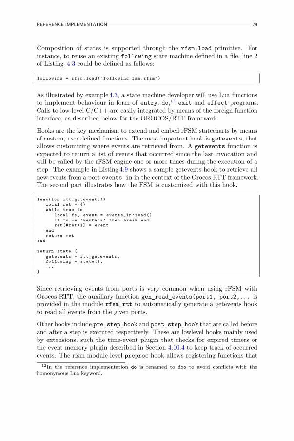
REFERENCE IMPLEMENTATION 79
Composition of states is supported through the rfsm.load primitive. Forinstance, to reuse an existing following state machine defined in a file, line 2of Listing 4.3 could be defined as follows:
following = rfsm.load (" following_fsm .rfsm ")
As illustrated by example 4.3, a state machine developer will use Lua functionsto implement behaviour in form of entry, do,12 exit and effect programs.Calls to low-level C/C++ are easily integrated by means of the foreign functioninterface, as described below for the OROCOS/RTT framework.
Hooks are the key mechanism to extend and embed rFSM statecharts by meansof custom, user defined functions. The most important hook is getevents, thatallows customizing where events are retrieved from. A getevents function isexpected to return a list of events that occurred since the last invocation andwill be called by the rFSM engine one or more times during the execution of astep. The example in Listing 4.9 shows a sample getevents hook to retrieve allnew events from a port events_in in the context of the Orocos RTT framework.The second part illustrates how the FSM is customized with this hook.
function rtt_getevents ()local ret = {}while true do
local fs , event = events_in :read ()if fs ~= 'NewData ' then break endret [# ret +1] = event
endreturn ret
end
return state {getevents = rtt_getevents ,following = state {},...
}
Since retrieving events from ports is very common when using rFSM withOrocos RTT, the auxillary function gen_read_events(port1, port2,... isprovided in the module rfsm_rtt to automatically generate a getevents hookto read all events from the given ports.
Other hooks include pre_step_hook and post_step_hook that are called beforeand after a step is executed respectively. These are lowlevel hooks mainly usedby extensions, such the time-event plugin that checks for expired timers orthe event memory plugin described in Section 4.10.4 to keep track of occurredevents. The rfsm module-level preproc hook allows registering functions that
12In the reference implementation do is renamed to doo to avoid conflicts with thehomonymous Lua keyword.
80 COORDINATING ROBOTIC TASKS AND SYSTEMS USING RFSM STATECHARTS
will be called at initalization time and can be used to preprocess or validate therFSM model prior to execution. An example use is for transforming platformindependent task models to rFSM hooks, as explained in Section 4.10.2.
4.9.1 Software Framework Integration
The reference implementation is implemented in pure Lua and has nodependencies whatsoever. This permits standalone use which is convenient fortesting and debugging of statecharts. To use the implementation in the contextof robotic software frameworks requires a plugin to make the primitives of theseframeworks available within Lua. We have developed such bindings for theOROCOS Real Time Toolkit (RTT) (Soetens 2006) that permit interacting withComponents, Services, Operations, Input- and Output Ports and data types. ARTT LuaComponent is an initially empty container into which Lua programscan be loaded. This approach permits treating Coordination components justas regular computational components that are configured to load Coordinationstatecharts. Event driven input ports can be used to trigger dormant componentsupon receiving events and output ports are used to emit events. Using thestandard communication primitives of a framework avoids duplicating thesemechanisms for the sake of Coordination.
4.9.2 Considerations for Hard Real-Time Execution
The RTT framework provides a hard real-time safe execution environment forcomponents. Naturally, real-time requirements exists also at the Coordinationlevel. Satisfying hard real-time constraints for interpreted, garbage collectedlanguages poses several challenges. Firstly, the allocation of memory must takeplace in a temporally deterministic way, which is typically not guaranteed to bethe case for the default memory allocators of general purpose operating systemssuch as Linux. Secondly, the recuperation of unused memory must take placein a way that does not interfere with the nominal execution.
Our approach achieves deterministic allocation by extending the Lua interpreterto use an O(1) memory allocator (Masmano, Ripoll, Balbastre, and Crespo2008). To achieve deterministic recuperation in critical real-time paths, theLua garbage collector is stopped and manually controlled. Further details canbe found in (Klotzbuecher, Soetens, and Bruyninckx 2010) (Klotzbuecher andBruyninckx 2011).
PATTERNS AND BEST PRACTICES 81
4.9.3 Representing Events
In the majority of examples and real applications we have represented eventsusing strings. While the rFSM implementation permits any comparable type tobe used, the string representation is convenient for humans and still reasonablyfast. Provided that memory is preallocated correctly, string events can even beused in hard real-time. Nevertheless, depending on the application, significantoverhead could be avoided by denoting events using numbers. To take advantageof the performance of the numeric representation and the readability of stringevents, the latter could be transformed to the former at load time using anrFSM pre-processing hook defined as a rFSM plugin.
4.10 Patterns and Best Practices
This Section discusses reoccurring patterns and best practices in roboticcoordination and their realization using rFSM.
4.10.1 Models of State Machine Progression
An important decision a statechart designer needs to take is to define how andwhen a statechart is advanced. Harel (Harel and Naamad 1996) describes twobasic approaches: the asynchronous and synchronous model (see Section 9, “Twomodels of time”). The synchronous model assumes that one step is executedevery time step, thereby causing the state machine to react to events andchanges that occurred since completion of the previous step. In contrast, theasynchronous model advances the state machine only upon receiving eventsand is typically configured to execute as long as events are available. Thesetwo models correspond to the paradigms of event-triggered (ET) and time-triggered (TT) systems (Kopetz 1993; Kopetz and Bauer 2003) and have receivedthorough treatment in literature. In summary, the TT architecture offers severaladvantages over the ET architecture, including exact predictability of temporalbehavior and allowing for systematic formal verification of temporal properties.In contrast, ET-systems generally require substantial testing to ensure thatdeadlines are met. Unfortunately, open and uncertain environments commonin robotics require significant effort to determine the necessary granulation ofobservation lattice and maximum execution times (Kopetz 1993).
While the rFSM model and reference implementation support both models,each model has different use-cases for which it is appropriate. The asynchronousmodel is best suited for coordination scenarios in which multiple components,
82 COORDINATING ROBOTIC TASKS AND SYSTEMS USING RFSM STATECHARTS
possibly running at different frequencies, are coordinated. To this end, adedicated Coordination component with its own activity is introduced. Whennew events are received, the state machine component is woken up and run (viathe run function) and permitted to execute until it goes idle (which happensif there are no events in the queue and there is no active do function). Inputevents can originate from various sources: user commands, error events fromcomputational components or filtered and processed raw events. Outputs mayconsist of performing actions such as starting or stopping components, creatingor destroying connections, invoking component services, or configuration ofparameters.
The synchronous execution model is suitable for coordination that takes placeat a fixed frequency. The typical use case is coordination of a single component.For each cycle of the computation, the step function of the FSM is invoked toadvance the state machine. This results in at most one transition being executed,taking into account all events that occurred since the last step. In contrastto the asynchronous model, the coordination can be executed convenientlywithin the activity of the coordinated host component. For instance, a PIDcontroller component can be decorated with a discrete task-aware coordinatorthat monitors and adjusts control parameters according to the current taskstate.
In practice, hybrid models combining both asynchronous and synchronousadvancing of state machines have often proven to be useful. This behaviourcan be achieved by connecting a periodic timer component in addition toother asynchronous event sources to the incoming event port of a coordinationcomponent. This way, the coordinator is guaranteed to wake up for processingat a minimum rate defined by the timer component. However, if events arrivein between timer events, the coordinator will react instantly.
Note that such timer events should be understood in the broadest possible senseof time: the events do not have to be emitted at fixed intervals of real-time,but may be raised according to a virtual task-specific clock. For instance, avirtual time could be derived from physical system properties such as the currentvelocity.
4.10.2 Defining Platform and Robot independent Coordina-tion Models
For reusing coordination models on different robots and with different softwareframeworks, it is necessary to avoid introducing dependencies on these aspects.A simple way to achieve this is to encapsulate the platform specific functions
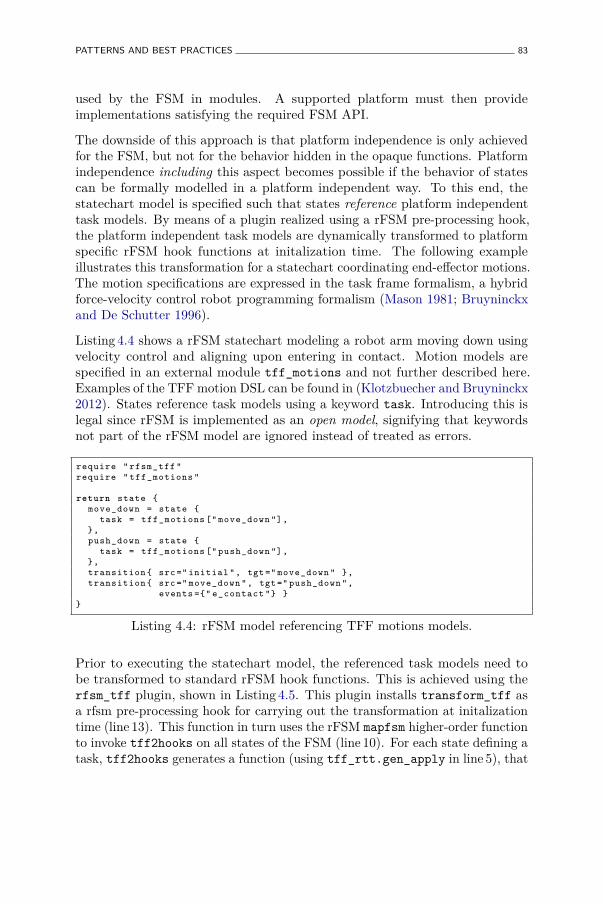
PATTERNS AND BEST PRACTICES 83
used by the FSM in modules. A supported platform must then provideimplementations satisfying the required FSM API.
The downside of this approach is that platform independence is only achievedfor the FSM, but not for the behavior hidden in the opaque functions. Platformindependence including this aspect becomes possible if the behavior of statescan be formally modelled in a platform independent way. To this end, thestatechart model is specified such that states reference platform independenttask models. By means of a plugin realized using a rFSM pre-processing hook,the platform independent task models are dynamically transformed to platformspecific rFSM hook functions at initalization time. The following exampleillustrates this transformation for a statechart coordinating end-effector motions.The motion specifications are expressed in the task frame formalism, a hybridforce-velocity control robot programming formalism (Mason 1981; Bruyninckxand De Schutter 1996).
Listing 4.4 shows a rFSM statechart modeling a robot arm moving down usingvelocity control and aligning upon entering in contact. Motion models arespecified in an external module tff_motions and not further described here.Examples of the TFF motion DSL can be found in (Klotzbuecher and Bruyninckx2012). States reference task models using a keyword task. Introducing this islegal since rFSM is implemented as an open model, signifying that keywordsnot part of the rFSM model are ignored instead of treated as errors.
require " rfsm_tff "require " tff_motions "
return state {move_down = state {
task = tff_motions [" move_down "],},push_down = state {
task = tff_motions [" push_down "],},transition { src =" initial ", tgt =" move_down " },transition { src =" move_down ", tgt =" push_down ",
events ={" e_contact "} }}
Listing 4.4: rFSM model referencing TFF motions models.
Prior to executing the statechart model, the referenced task models need tobe transformed to standard rFSM hook functions. This is achieved using therfsm_tff plugin, shown in Listing 4.5. This plugin installs transform_tff asa rfsm pre-processing hook for carrying out the transformation at initalizationtime (line 13). This function in turn uses the rFSM mapfsm higher-order functionto invoke tff2hooks on all states of the FSM (line 10). For each state defining atask, tff2hooks generates a function (using tff_rtt.gen_apply in line 5), that
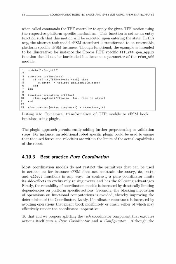
84 COORDINATING ROBOTIC TASKS AND SYSTEMS USING RFSM STATECHARTS
when called commands the TFF controller to apply the given TFF motion usingthe respective platform specific mechanism. This function is set as an entryfunction such that this motion will be executed upon entering the state. In thisway, the abstract task model rFSM statechart is transformed to an executable,platform specific rFSM instance. Though functional, the example is intendedto be illustrative; for instance the Orocos RTT specific tff_rtt.gen_applyfunction should not be hardcoded but become a parameter of the rfsm_tffmodule.
1 module (" rfsm_tff ")23 function tff2hooks (s)4 if tff. is_TFFMotion (s.task) then5 s. entry = tff_rtt . gen_apply (s.task)6 end7 end89 function transform_tff (fsm)
10 rfsm. mapfsm (tff2hooks , fsm , rfsm. is_state )11 end1213 rfsm. preproc [# rfsm. preproc +1] = transform_tff
Listing 4.5: Dynamical transformation of TFF models to rFSM hookfunctions using plugin.
The plugin approach permits easily adding further preprocessing or validationsteps. For instance, an additional robot specific plugin could be used to ensurethat the used forces and velocities are within the limits of the actual capabilitiesof the robot.
4.10.3 Best practice Pure Coordination
Most coordination models do not restrict the primitives that can be usedin actions, as for instance rFSM does not constrain the entry, do, exit,and effect functions in any way. In contrast, a pure coordinator limitsits side-effects to exclusively raising events and has the following advantages.Firstly, the reusability of coordination models is increased by drastically limitingdependencies on platform specific actions. Secondly, the blocking invocationof operations on functional computations is avoided, thereby improving thedeterminism of the Coordinator. Lastly, Coordinator robustness is increased byavoiding operations that might block indefinitely or crash, either of which mayeffectively render the coordinator inoperative.
To that end we propose splitting the rich coordinator component that executesactions itself into a Pure Coordinator and a Configurator. Although the
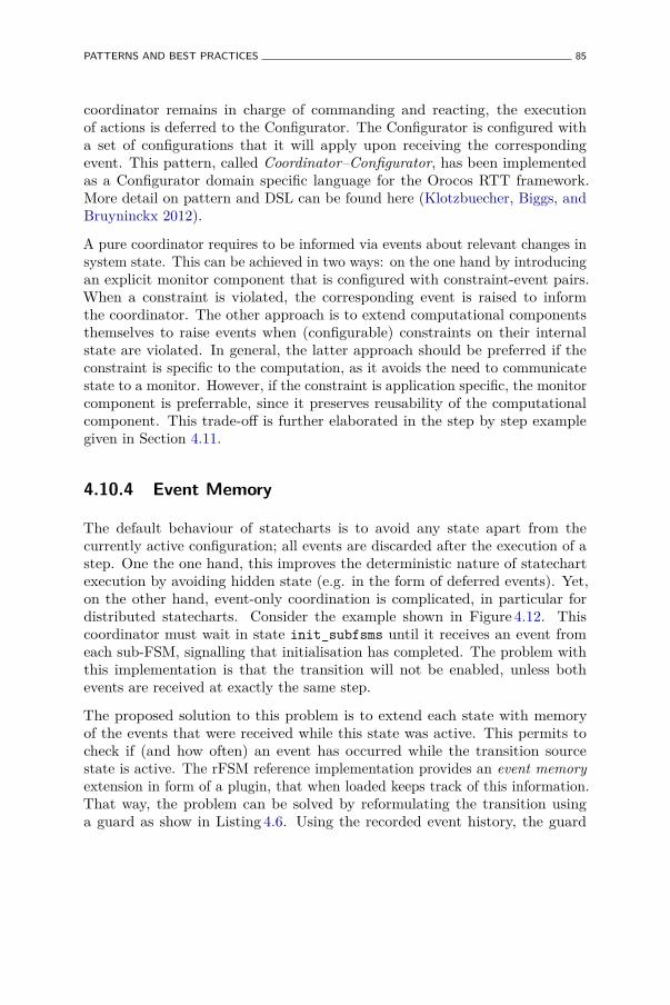
PATTERNS AND BEST PRACTICES 85
coordinator remains in charge of commanding and reacting, the executionof actions is deferred to the Configurator. The Configurator is configured witha set of configurations that it will apply upon receiving the correspondingevent. This pattern, called Coordinator–Configurator, has been implementedas a Configurator domain specific language for the Orocos RTT framework.More detail on pattern and DSL can be found here (Klotzbuecher, Biggs, andBruyninckx 2012).
A pure coordinator requires to be informed via events about relevant changes insystem state. This can be achieved in two ways: on the one hand by introducingan explicit monitor component that is configured with constraint-event pairs.When a constraint is violated, the corresponding event is raised to informthe coordinator. The other approach is to extend computational componentsthemselves to raise events when (configurable) constraints on their internalstate are violated. In general, the latter approach should be preferred if theconstraint is specific to the computation, as it avoids the need to communicatestate to a monitor. However, if the constraint is application specific, the monitorcomponent is preferrable, since it preserves reusability of the computationalcomponent. This trade-off is further elaborated in the step by step examplegiven in Section 4.11.
4.10.4 Event Memory
The default behaviour of statecharts is to avoid any state apart from thecurrently active configuration; all events are discarded after the execution of astep. One the one hand, this improves the deterministic nature of statechartexecution by avoiding hidden state (e.g. in the form of deferred events). Yet,on the other hand, event-only coordination is complicated, in particular fordistributed statecharts. Consider the example shown in Figure 4.12. Thiscoordinator must wait in state init_subfsms until it receives an event fromeach sub-FSM, signalling that initialisation has completed. The problem withthis implementation is that the transition will not be enabled, unless bothevents are received at exactly the same step.
The proposed solution to this problem is to extend each state with memoryof the events that were received while this state was active. This permits tocheck if (and how often) an event has occurred while the transition sourcestate is active. The rFSM reference implementation provides an event memoryextension in form of a plugin, that when loaded keeps track of this information.That way, the problem can be solved by reformulating the transition usinga guard as show in Listing 4.6. Using the recorded event history, the guard
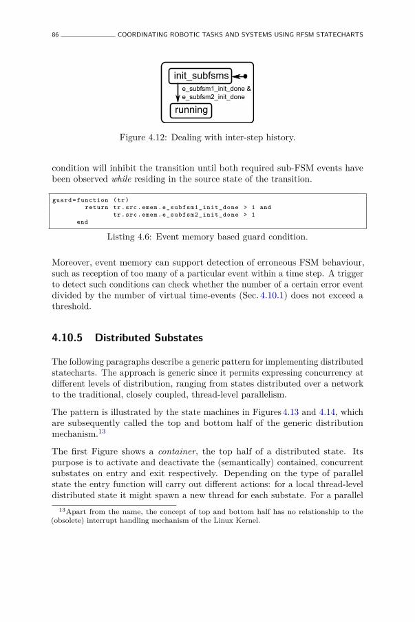
86 COORDINATING ROBOTIC TASKS AND SYSTEMS USING RFSM STATECHARTS
init_subfsms
running
e_subfsm1_init_done &e_subfsm2_init_done
Figure 4.12: Dealing with inter-step history.
condition will inhibit the transition until both required sub-FSM events havebeen observed while residing in the source state of the transition.
guard = function (tr)return tr.src.emem. e_subfsm1_init_done > 1 and
tr.src.emem. e_subfsm2_init_done > 1end
Listing 4.6: Event memory based guard condition.
Moreover, event memory can support detection of erroneous FSM behaviour,such as reception of too many of a particular event within a time step. A triggerto detect such conditions can check whether the number of a certain error eventdivided by the number of virtual time-events (Sec. 4.10.1) does not exceed athreshold.
4.10.5 Distributed Substates
The following paragraphs describe a generic pattern for implementing distributedstatecharts. The approach is generic since it permits expressing concurrency atdifferent levels of distribution, ranging from states distributed over a networkto the traditional, closely coupled, thread-level parallelism.
The pattern is illustrated by the state machines in Figures 4.13 and 4.14, whichare subsequently called the top and bottom half of the generic distributionmechanism.13
The first Figure shows a container, the top half of a distributed state. Itspurpose is to activate and deactivate the (semantically) contained, concurrentsubstates on entry and exit respectively. Depending on the type of parallelstate the entry function will carry out different actions: for a local thread-leveldistributed state it might spawn a new thread for each substate. For a parallel
13Apart from the name, the concept of top and bottom half has no relationship to the(obsolete) interrupt handling mechanism of the Linux Kernel.

PATTERNS AND BEST PRACTICES 87
entry: activate_substates()exit: deactivate_substates()
distributed_state
Figure 4.13: Distributed state.
distributed_substate
e_sub_activate e_sub_inactivate
inactive
active
rfsm.load(file)
Figure 4.14: Distributed substate.
substate distributed over the network it might connect to a running and waitinginstance. Substate activation and deactivation is achieved simply by sendingthe corresponding events to the bottom half.
Each distributed substate, the bottom half, is formed by a generic substate asshown in Figure 4.14. This state contains two states active and inactive thatare connected by transitions. The active state includes the application specificstate machine, that is entered per default via its initial connector once theactive state is entered. This way, the top half can control the execution of thebottom half by sending it the events e_sub_activate and e_sub_inactivate.Likewise, by observing the active state of the bottom half the top half candetermine when all substates have successfully been entered or exited.
Using this pattern formed by two FSM, any hierarchical state machine canbe distributed independently of the form of distribution and obeying therules of hierarchical statecharts. The only requirement is that events canbe communicated between distributed instances.
Communication and Deployment By distributing state machines as describedabove, the communication between these instances is made explicit. Toimplement this, an asynchronous message passing mechanism (to communicateevents) is most suitable. Communication is required for notifying a distributedstate to activate or deactivate its sub-state machines, for propagating eventsbetween the two halves and for notifying the top half about state changes in
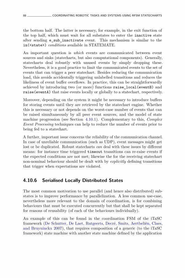
88 COORDINATING ROBOTIC TASKS AND SYSTEMS USING RFSM STATECHARTS
the bottom half. The latter is necessary, for example, in the exit function ofthe top half, which must wait for all substates to enter the inactive stateafter sending e_sub_inactivate event. This mechanism is similar to thein(<state>) conditions available in STATEMATE.
An important question is which events are communicated between eventsources and sinks (statecharts, but also computational components). Generally,statecharts deal robustly with unused events by simply dropping these.Nevertheless, it is a good practice to limit the communicated events to the set ofevents that can trigger a peer statechart. Besides reducing the communicationload, this avoids accidentally triggering unlabelled transitions and reduces thelikeliness of event buffer overflows. In practice, this can be straightforwardlyachieved by introducing two (or more) functions raise_local(eventB) andraise(eventA) that raise events locally or globally to a statechart, respectively.
Moreover, depending on the system it might be necessary to introduce buffersfor storing events until they are retrieved by the statechart engine. Whetherthis is necessary or not depends on the worst-case number of events that canbe raised simultaneously by all peer event sources, and the model of statemachine progression (see Section 4.10.1). Complementary to this, ComplexEvent Processing techniques can help to reduce the number of events prior tobeing fed to a statechart.
A further, important issue concerns the reliability of the communication channel.In case of unreliable communication (such as UDP), event messages might getlost or be duplicated. Robust statecharts can deal with these issues by differentmeans: for instance time triggered timeout transitions can re-raise events ifthe expected conditions are not met; likewise the for the receiving statechartnon-nominal behaviour should be dealt with by explicitly defining transitionsthat trigger when expectations are violated.
4.10.6 Serialised Locally Distributed States
The most common motivation to use parallel (and hence also distributed) sub-states is to improve performance by parallelization. A less common use-case,nevertheless more relevant to the domain of coordination, is for combiningbehaviours that must be executed concurrently but that shall be kept separatedfor reasons of reusability (of each of the behaviours individually).
An example of this can be found in the coordination FSM of the iTaSCframework (De Schutter, De Laet, Rutgeerts, Decré, Smits, Aertbeliën, Claes,and Bruyninckx 2007), that requires composition of a generic (to the iTaSCframework) state machine with another state machine defined by the application

PATTERNS AND BEST PRACTICES 89
developer. The generic state machine first triggers all task-level FSMs to runat the right time. The second, user-defined FSM implements the overall taskexecution. Although both parts must always be executed after each other(first the generic, then the user defined) it is desirable to keep them specifiedseparately to be able to reuse the generic part. To achieve this composition, astate named serialised-locally-distributed state (SLDS) was introduced. Thisname originates from the fact that the sub-states are advanced one by one in aserialised way in the same activity (thread) as the parent state machine. Moreconcretely, a SLDS state can conveniently be realised as a leaf state that triggersall substates in its do function. This way, both FSMs can be composed fromseparate models at a late stage, during the loading of the SLDS state.
To concisely specify the behaviour of this type of state, additional propertiesmust be defined: in which (partial) order shall the substates be advanced, shallthis take place by invoking step (and how often?) or run? Shall non-idlesub-states result in the do of the SLDS to become non-idle too? As a sidenote, the considerable number of parameters required by the implementation ofthis most simple form of parallel state illustrates the complexity introduced bythis family of model elements and confirms our approach to exclude these asprimitives.
4.10.7 Discrete Preview Coordination
Discrete Preview Coordination is inspired by the concept of preview control(Sheridan 1992), but also by compiler branch-prediction techniques such as gcc’s(GNU Compiler Collection) __builtin_expect. The basic idea is to exploitknowledge about the future behaviour of a system to optimise the current actions.In order to apply preview techniques to discrete coordination, we extend thecore rFSM model as follows: transitions are extended with an optional Booleanlikely attribute and states with an additional prepare action. While checkingfor enabled transitions from the currently active states, the preview mechanismwill additionally check for transitions that are likely. If such a transition isfound, the transition target state’s prepare action is executed. This way, theprepare action can be used to prepare the activity of the respective state inexpectation that it might be entered next.
The use of preview coordination is illustrated by the example statechart shownin Figure 4.15. This statechart models a mobile robot skill for retrieving anobject. Object retrieval consists of three nominal substates of first approachingthe target location, then moving the arm close to the object to be graspedand lastly grasping the object. Additionally, the situation of unexpected
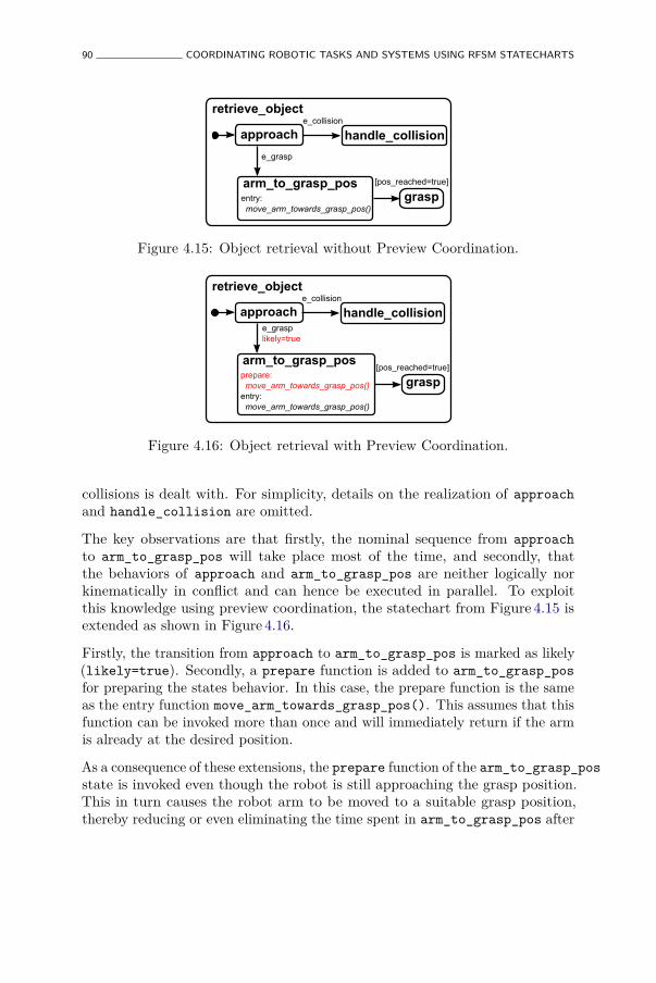
90 COORDINATING ROBOTIC TASKS AND SYSTEMS USING RFSM STATECHARTS
approach
retrieve_object
handle_collision
grasp
e_collision
e_grasp
arm_to_grasp_posentry: move_arm_towards_grasp_pos()
[pos_reached=true]
Figure 4.15: Object retrieval without Preview Coordination.
approach
retrieve_object
handle_collision
grasp
e_collision
e_grasplikely=true
arm_to_grasp_posprepare: move_arm_towards_grasp_pos()entry: move_arm_towards_grasp_pos()
[pos_reached=true]
Figure 4.16: Object retrieval with Preview Coordination.
collisions is dealt with. For simplicity, details on the realization of approachand handle_collision are omitted.
The key observations are that firstly, the nominal sequence from approachto arm_to_grasp_pos will take place most of the time, and secondly, thatthe behaviors of approach and arm_to_grasp_pos are neither logically norkinematically in conflict and can hence be executed in parallel. To exploitthis knowledge using preview coordination, the statechart from Figure 4.15 isextended as shown in Figure 4.16.
Firstly, the transition from approach to arm_to_grasp_pos is marked as likely(likely=true). Secondly, a prepare function is added to arm_to_grasp_posfor preparing the states behavior. In this case, the prepare function is the sameas the entry function move_arm_towards_grasp_pos(). This assumes that thisfunction can be invoked more than once and will immediately return if the armis already at the desired position.
As a consequence of these extensions, the prepare function of the arm_to_grasp_posstate is invoked even though the robot is still approaching the grasp position.This in turn causes the robot arm to be moved to a suitable grasp position,thereby reducing or even eliminating the time spent in arm_to_grasp_pos after
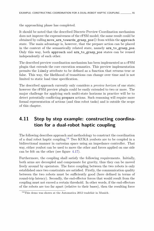
EXAMPLE: CONSTRUCTING COORDINATION FOR A DUAL-ROBOT HAPTIC COUPLING 91
the approaching phase has completed.
It should be noted that the described Discrete Preview Coordination mechanismdoes not improve the expressiveness of the rFSM model; the same result could beobtained by calling move_arm_towards_grasp_pos() from within the approachstate. The main advantage is, however, that the prepare action can be placedin the context of the semantically related state, namely arm_to_grasp_pos.Only this way, both approach and arm_to_grasp_pos states can be reusedindependently of each other.
The described preview coordination mechanism has been implemented as a rFSMplugin that extends the core execution semantics. This preview implementationpermits the likely attribute to be defined as a function that returns true orfalse. This way, the likelihood of transitions can change over time and is notlimited to static load time specification.
The described approach currently only considers a preview horizon of one state;however the rFSM preview plugin could be easily extended to two or more. Themajor challenge for applying such multi-state horizons in practice will be todetect potentially conflicting prepare actions. Such reasoning will require moreformal representation of actions (and thus robot tasks) and is outside the scopeof this chapter.
4.11 Step by step example: constructing coordina-tion for a dual-robot haptic coupling
The following describes approach and methodology to construct the coordinationof a dual robot haptic coupling.14 Two KUKA youbots are to be coupled in abidirectional manner in cartesian space using an impedance controller. Thatway, either youbot can be used to move the other and forces applied on one sidecan be felt on the other (see figure 4.17).
Furthermore, the coupling shall satisfy the following requirements. Initially,both arms are decoupled and compensate for gravity, thus they can be movedfreely around by operators. The force coupling between the two robots is onlyestablished once two constraints are satisfied. Firstly, the communication qualitybetween the two robots must be sufficiently good (here defined in terms ofround-trip latency). Secondly, the end-effector forces that would result from thecoupling must not exceed a certain threshold. In other words, if the end-effectorsof the robots are too far apart (relative to their bases), then the resulting force
14This demo was shown at the Automatica 2012 tradefair in Munich.
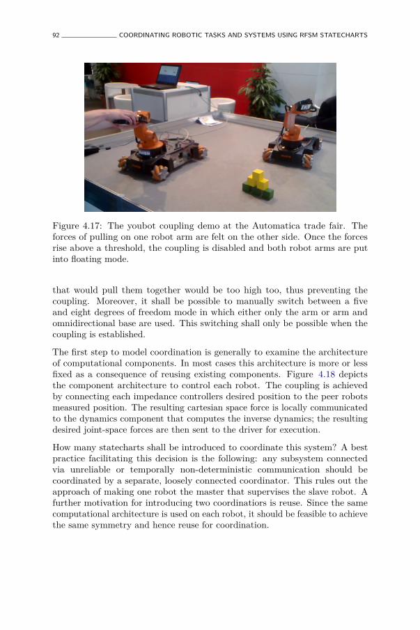
92 COORDINATING ROBOTIC TASKS AND SYSTEMS USING RFSM STATECHARTS
Figure 4.17: The youbot coupling demo at the Automatica trade fair. Theforces of pulling on one robot arm are felt on the other side. Once the forcesrise above a threshold, the coupling is disabled and both robot arms are putinto floating mode.
that would pull them together would be too high too, thus preventing thecoupling. Moreover, it shall be possible to manually switch between a fiveand eight degrees of freedom mode in which either only the arm or arm andomnidirectional base are used. This switching shall only be possible when thecoupling is established.
The first step to model coordination is generally to examine the architectureof computational components. In most cases this architecture is more or lessfixed as a consequence of reusing existing components. Figure 4.18 depictsthe component architecture to control each robot. The coupling is achievedby connecting each impedance controllers desired position to the peer robotsmeasured position. The resulting cartesian space force is locally communicatedto the dynamics component that computes the inverse dynamics; the resultingdesired joint-space forces are then sent to the driver for execution.
How many statecharts shall be introduced to coordinate this system? A bestpractice facilitating this decision is the following: any subsystem connectedvia unreliable or temporally non-deterministic communication should becoordinated by a separate, loosely connected coordinator. This rules out theapproach of making one robot the master that supervises the slave robot. Afurther motivation for introducing two coordinatiors is reuse. Since the samecomputational architecture is used on each robot, it should be feasible to achievethe same symmetry and hence reuse for coordination.
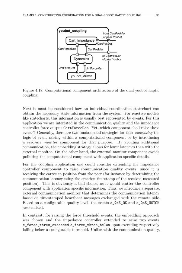
EXAMPLE: CONSTRUCTING COORDINATION FOR A DUAL-ROBOT HAPTIC COUPLING 93
youbot_driver
Cart_Impedance
Dynamics
youbot_coupling
CartForceDes CartPosMsr
JntForceDsr JntForceMsr
from CartPosMsr of peer Youbot
to CartPosDsrof peer Youbot
CartPosDsr
Figure 4.18: Computational component architecture of the dual youbot hapticcoupling.
Next it must be considered how an individual coordination statechart canobtain the necessary state information from the system. For reactive modelslike statecharts, this information is usually best represented by events. For thisapplication we are interested in the communication quality and the impedancecontroller force output CartForceDes. Yet, which component shall raise theseevents? Generally, there are two fundamental strategies for this: embedding thelogic of event raising within a computational component or by introducinga separate monitor component for that purpose. By avoiding additionalcommunication, the embedding strategy allows for lower latencies than with theexternal monitor. On the other hand, the external monitor component avoidspolluting the computational component with application specific details.
For the coupling application one could consider extending the impedancecontroller component to raise communication quality events, since it isreceiving the cartesian position from the peer (for instance by determining thecommunication latency using the creation timestamp of the received measuredposition). This is obviously a bad choice, as it would clutter the controllercomponent with application specific information. Thus, we introduce a separate,external communication monitor that determines the communication latencybased on timestamped heartbeat messages exchanged with the remote side.Based on a configurable quality level, the events e_QoS_OK and e_QoS_NOTOKare emitted.
In contrast, for raising the force threshold events, the embedding approachwas chosen and the impedance controller extended to raise two eventse_force_thres_exceeded e_force_thres_below upon exceeding respectivelyfalling below a configurable threshold. Unlike with the communication quality,
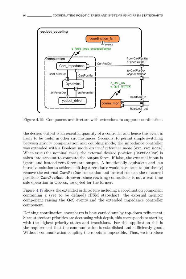
94 COORDINATING ROBOTIC TASKS AND SYSTEMS USING RFSM STATECHARTS
comm_mon
coordination_fsm
computation
Cart_Impedance
Dynamics
youbot_coupling
e_force_thres_exceeded/below
e_QoS_OKe_QoS_NOTOK
CartForceDes CartPosMsr
CartPosDsr
youbot_driver
JntForceDsr JntForceMsr
events
from CartPosMsr of peer Youbot
to CartPosDsrof peer Youbot
heartbeat_in
heartbeat_out
Figure 4.19: Component architecture with extensions to support coordination.
the desired output is an essential quantity of a controller and hence this event islikely to be useful in other circumstances. Secondly, to permit simple switchingbetween gravity compensation and coupling mode, the impedance controllerwas extended with a Boolean mode external reference mode (ext_ref_mode).When true (the nominal case), the external desired position (CartPosDsr) istaken into account to compute the output force. If false, the external input isignore and instead zero forces are output. A functionally equivalent and lessintrusive solution to achieve emitting a zero force would have been to (on-the-fly)remove the external CartPosDsr connection and instead connect the measuredpositions CartPosMsr. However, since rewiring connections is not a real-timesafe operation in Orocos, we opted for the former.
Figure 4.19 shows the extended architecture including a coordination componentcontaining a (yet to be defined) rFSM statechart, the external monitorcomponent raising the QoS events and the extended impedance controllercomponent.
Defining coordination statecharts is best carried out by top-down refinement.Since statechart priorities are decreasing with depth, this corresponds to startingwith the highest priority states and transitions. For this application this isthe requirement that the communication is established and sufficiently good.Without communication coupling the robots is impossible. Thus, we introduce

EXAMPLE: CONSTRUCTING COORDINATION FOR A DUAL-ROBOT HAPTIC COUPLING 95
two states synchronized and unsynchronized that model this requirement(Figure 4.20).
coupling coordination
unsynchronized
synchronized
e_QoS_OK e_QoS_NOTOK
Figure 4.20: Constructing the coordinator, step 1: modeling the communicationquality constraint.
Next we refine the systems behavior by extending the synchronized state(entered when the communication is good enough) by adding two substatesgravity_comp and copying (Figure 4.21). gravity_comp represents the state inwhich the impedance controller output force CartForceDes is too high and hencegravity compensation is enabled. In copying the actual coupling is establishedby enabling external reference mode. Conversely, external reference mode isdisabled upon exiting the copying state, since only that way it is guaranteed thatthis mode is disabled no matter how copying is exited. For instance, if externalreference mode were only disabled in the entry function of gravity_comp, thetransition to unsynchronized triggered by an e_QoS_NOTOK when in copyingwould result in entering unsynchronized with external reference mode stillenabled.
Note that in contrast to the toplevel transitions between unsynchronized andsynchronized, the transitions between gravity_comp and copying make useof a guard condition above_force_thres() instead of being triggered by events.The reason for this is that upon entering the synchronized state the impedancecontroller forces will already be either too high or not and the correspondingevents already raised. Thus, if these transitions were triggered only by events,the gravity_comp state might erronously remain active, unless by chance thiscondition just changes after entering gravity_comp.
function above_force_thres ()local flow_status , value = force_thres_ex :read ()if flow_status == 'NoData ' then return false endelse return value end
end
Listing 4.7: Implementation of above_force_thres guard condition.
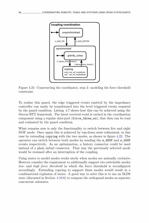
96 COORDINATING ROBOTIC TASKS AND SYSTEMS USING RFSM STATECHARTS
coupling coordination
unsynchronized
synchronized
e_QoS_OK e_QoS_NOTOK
gravity_comp
copying
[ ! above_force_thres() ]
[ above_force_thres() ]
entry: ext_ref_mode(true)exit: ext_ref_mode(false)
Figure 4.21: Constructing the coordinator, step 2: modeling the force thresholdconstraint.
To realize this guard, the edge triggered events emitted by the impedancecontroller can easily be transformed into the level triggered events requiredby the guard condition. Listing 4.7 shows how this can be achieved using theOrocos RTT framework. The latest received event is cached in the coordinationcomponent using a regular data-port (force_thres_ex), that then can be readand evaluated by the guard condition.
What remains now is only the functionality to switch between five and eightDOF mode. Once again this is achieved by top-down state refinement, in thiscase by extending copying with the two modes, as shown in figure 4.22. Theoperator can switch between both modes by sending the e_8DOF and e_5DOFevents respectively. As an optimization, a history connector could be usedinstead of a plain initial connector. That way the previously selected modewould be resumed after an interruption of the coupling.
Using states to model modes works nicely when modes are mutually exclusive.However consider the requirement to additionally support two switchable modeslow- and high force threshold in which the force threshold is reconfiguredaccordingly. Extending copying to support these modes would result in acombinatorial explosion of states. A good way to solve this is to use an SLDSstate (discussed in Section 4.10.6) to compose the orthogonal modes as separate,concurrent substates.
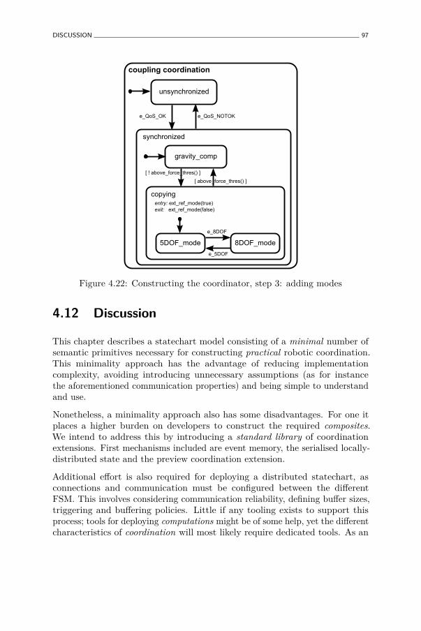
DISCUSSION 97
coupling coordination
unsynchronized
synchronized
e_QoS_OK e_QoS_NOTOK
gravity_comp
copying
[ ! above_force_thres() ]
[ above_force_thres() ]
entry: ext_ref_mode(true)exit: ext_ref_mode(false)
8DOF_mode5DOF_mode
e_8DOF
e_5DOF
Figure 4.22: Constructing the coordinator, step 3: adding modes
4.12 Discussion
This chapter describes a statechart model consisting of a minimal number ofsemantic primitives necessary for constructing practical robotic coordination.This minimality approach has the advantage of reducing implementationcomplexity, avoiding introducing unnecessary assumptions (as for instancethe aforementioned communication properties) and being simple to understandand use.
Nonetheless, a minimality approach also has some disadvantages. For one itplaces a higher burden on developers to construct the required composites.We intend to address this by introducing a standard library of coordinationextensions. First mechanisms included are event memory, the serialised locally-distributed state and the preview coordination extension.
Additional effort is also required for deploying a distributed statechart, asconnections and communication must be configured between the differentFSM. This involves considering communication reliability, defining buffer sizes,triggering and buffering policies. Little if any tooling exists to support thisprocess; tools for deploying computations might be of some help, yet the differentcharacteristics of coordination will most likely require dedicated tools. As an

98 COORDINATING ROBOTIC TASKS AND SYSTEMS USING RFSM STATECHARTS
example, having multiple simultaneously active writers communicating datato a single reader is often an erroneous situation for Computations (e.g. onlyone controller may command a robot at a time). Conversely, it is common toconnect multiple, active event sources to one Coordination statechart.
For using the rFSM model in the context of complex distributed robotic systems,we propose to make exclusive use of pure coordination. Pure coordinationcan be achieved by rigorously separating the concerns of Computations fromCoordination; more concretely by limiting Coordination actions to exclusivelyraising events. The benefits of adhering to this best-practice are increasedrobustness and reusability of Coordination. The drawback, however is that asof today few components provide sufficiently expressive constraint configurationinterfaces; one reason for this being presumably the lack of a generic mechanismto specify condition-event pairs on internal state of computations.
One motivation for choosing graphical models (as statecharts) to model complexsystems is their apparent ease to be understood by humans. Yet surprisinglyfew tools exist to visualise graphical models (online or offline) by performingautomatic layout and rendering of the textual representation. The tool mostwidely used for this purpose is probably graphviz (Gansner and North 2000),that is also used by the rFSM reference implementation for visualising statechartmodels. Unfortunately, the generated representation, especially when involvinghierarchical states, is often suboptimal15; significant fine tuning of layoutparameters only resulted in a marginal improvement. Nevertheless, this simpletool has proven invaluable to validate that a model specified in textual formdoes indeed correspond to the graphical model the developer has in mind. Weintend to address this topic in future work.
4.13 Conclusion and Future Work
We have presented a lightweight Coordination statechart model that is derivedby analysing and extracting a minimal subset of model elements from existingformalism. The proposed rFSM model is graphically a subset of UML withsimplified execution semantics derived from the well known STATEMATEstatecharts. By selective inclusion of model elements, many of the cornercases and additional rules required by existing formalism can be avoided, thussimplifying both implementation and coordination models themselves.
Instead of providing a rich set of built-in features for all possible use-cases, the rFSM model advocates dealing with complexity by composition.
15Optimality defined by how a human would draw a statechart, as is the case with allfigures (apart from Figure 4.10) in this chapter.
CONCLUSION AND FUTURE WORK 99
Composition means both local hierarchical composition of Statecharts ordistributed composition as described in Section 4.10.5 as well as composition ofcore execution semantics with run-time extensions such as event memory.
To back up these claims we implemented an extensible, framework independent,real-time safe reference implementation based on the Lua scripting language.The featurewise almost complete rFSM core engine currently amounts to lessthan 830 lines of code16. This reference implementation has successfully beenintegrated into the OROCOS RTT software framework and applied to a widerange of use-cases.
Moreover, we describe several best-practice patterns of robotic task and systemcoordination that were discovered during our work. These patterns serveto highlight frequent coordination design issues together with best practicesolutions, with the goal of fostering adoption of the rFSM model.
Up to now, the described rFSM model has been sufficient to describe all robotictask and system coordination we encountered, hence there currently seems noneed for extensions to the core model. On the other hand we observe a severelack of tools to support creating, deploying and visualising rFSM statechartsand Coordination models in general. We intend to address this in future work.
16Calculated using the cloc(1) tool.


Chapter 5
Reusable hybrid force-velocitycontrolled motionspecifications with executabledomain specific languages∗
5.1 Abstract
Most of today’s robotic task descriptions are designed for a single software andhardware platform and thus can not be reused without modifications. Thiswork follows the meta-model approach of Model Driven Engineering (MDE)to introduce the concepts of Domain Specific Languages (DSL) and of ModelTransformations to the domain of hybrid force-velocity controlled robot tasks,as expressed in (i) the Task Frame formalism (TFF), and (ii) a Statechartmodel representing the discrete coordination between TFF tasks. The resultis a representation in MDE’s M0, M1, M2 and M3 form, with increasinglyrobot and software independent representations, that do remain instantaneouslyexecutable, except obviously for the M3 metametamodel. The Platform SpecificModel information can be added in three steps: (i) the type of the hybridforce-velocity controlled task, (ii) the hardware properties of the robot, tool and
∗This chapter is based on: Klotzbücher, M., Smits, R., Bruyninckx, H., and De Schutter,J. Reusable hybrid force-velocity controlled motion specifications with executable domainspecific languages. In Proc. IEEE/RSJ Int. Conf. Int. Robots and Systems (San Francisco,California, 2011), pp. 4684–4689.
101
102 REUSABLE MOTION SPECIFICATIONS WITH EXECUTABLE DSL
sensor, and (iii) the software properties of the applied execution framework. Wedemonstrate the presented approach by means of an alignment task executedon a Willow Garage PR2 and a KUKA Light Weight Robot (LWR) arm.
5.2 Introduction
The Task Frame formalism (TFF) was introduced by Mason (Bruyninckx andDe Schutter 1996; De Schutter and Van Brussel 1988; Mason 1981), to specifyhybrid force position/velocity control operations. This formalism identifies sixforce- and velocity-controlled directions, coinciding with the axes of a singleframe, the Task Frame or Compliance Frame. The TFF abstracts from the exactrobotics hardware (manipulator, sensor, tool) and software (hybrid force/velocitycontroller) that are used to execute the task, but these “platform-dependencies”are introduced implicitly via the force and/or velocity setpoints that are requiredin each degree of freedom. Although being used in practice by many labs andin many applications, the TFF representation has never been standardized,which would be the first step towards reuse of the same task specification overmultiple applications and robot platforms. This chapter makes a first attempttowards such “standardization”, in the established context of the Model DrivenEngineering (MDE) framework1, more in particular, by using the conceptsof (i) a Domain Specific Language (DSL), and (ii) metamodeling, (Atkinsonand Kühne 2003; Flatscher 2002). The added value of this work lies in thestructured way to deal with various platform-dependencies: (i) the type ofthe hybrid force-velocity controlled task, (ii) the hardware properties of therobot, tool and sensor, and (iii) the software properties of the applied executionframework.
Domain Specific Languages are lightweight programming languages designed toconcisely express the concepts of a particular domain. Commonly two typesare distinguished: internal and external DSL. The first are built on top of anexisting language while the second are developed from scratch. By reusingexisting infrastructure, internal DSL are much easier to create and maintainthan external ones. The only disadvantage of an internal DSL is that itssyntax is constrained by the host language. In practice this limitation is oftenacceptable given the reduction in development time and the ease of combiningDSLs together. In this work we define multiple internal DSL to facilitateprogramming with the TFF. The goal of this is threefold: firstly to supportthe programmer in constructing complex behaviors in an intuitive way (via
1The Object Management Group (Object Management Group b) is the main driver ofstandardization in the context of Model Driven Engineering, for which it uses the trademarkedname Model Driven Architecture.

INTRODUCTION 103
the familiar concept of a finite state machine, secondly by facilitating reuse ofthese behaviors or parts thereof in new applications (via the introduction of aTFF-centric DSL), and thirdly to cleanly separate the generic behavior fromrobot hardware and software framework dependent aspects (via MDE’s fourlevels of modeling, as depicted in Figure 5.1).
Figure 5.1) sketches a systematic approach to model a certain domain in fourlevels of abstraction; in this chapter’s context of TFF robot tasks, these fourlevels have the following meaning:
M0: the level of the concrete implementations, for example, using particularC++ libraries for execution of TFF specifications, using the Orocos and/orROS framework.
M1: the level of a platform-specific TFF specification DSL, using the force andvelocity setpoints that are appropriate for, for example, the KUKA LWR,or the PR2.
M2: the level of the platform-independent TFF specification DSL, whichprovides a parameterized template for each sub-task, in which the platform-specific setpoints have to be filled in later.
M3: the highest level of abstraction, that is, the model that represents all theconstraints that a DSL has to satisfy in order to be a valid TFF DSL.
This chapter gives DSL implementations on the M1 and M2 levels, and assumesthat an implementation for the M0 level is available. For the M3 level the Ecorelanguage is used.2
To illustrate our approach, we modeled and implemented an object alignmenttask, and executed it on different robot platforms (see Figures 5.2–5.3). Thistask is one of the simplest ones that still shows all relevant concepts introducedin this chapter. (The focus of this chapter is on the concepts, and noton the complexity or innovation of this particular task.) Figure 5.2shows the steps of the alignment task executed by a KUKA LWR. The top-leftimage shows the unaligned initial position of the manipulator, from which thearm holding the object moves down with a constant velocity until contact witha surface is detected (top right). This triggers a transition to a force-controlled,pushing-down motion which causes the end effector to align perpendicular tothe surface. After the alignment has completed, a sliding motion (velocitycontrol in the direction towards the right-hand side fixture, and force controlperpendicular to the surface) is executed (bottom-left image). When contact is
2Ecore is the M3-level metametamodel language standardized by the Eclipse EMFconsortium, www.eclipse.org/emf.

104 REUSABLE MOTION SPECIFICATIONS WITH EXECUTABLE DSL
metametamodel
metamodel(DSL)
metamodel(DSL)
domainmodel
domainmodel
domainmodel
conforms-to
conforms-to
M3
M2
M1
M0
instance of
Real-world systems
DSLDesigner
DSLUser
Figure 5.1: The four levels in OMG’s standard for the role of Domain SpecificLanguages in Model Driven Engineering.
established with the fixture, a sideways pushing motion is activated, resultingin alignment against the fixture (bottom right image). Figure 5.3 shows thesame alignment task being executed by one arm of a PR2 robot.
5.2.1 Related work
The first integrated programming and simulation environment for the TaskFrame Formalism was COMRADE (Bruyninckx and De Schutter 1996; Van dePoel, Witvrouw, Bruyninckx, and De Schutter 1993). COMRADE reduced thetask specification into three steps: (i) initialize the model by specifying the TaskFrame and selecting the force- and velocity-controlled directions, (ii) choosethe desired values for each force and velocity and (iii) specify the terminationconditions for the motion. Coordination of such TFF tasks into possiblycomplex sets of tasks and subtasks, was introduced by (Finkemeyer, Kröger,and Wahl 2005), using finite state automata. This chapter’s DSLs encompassboth aspects (task execution as well as the coordination of the execution ofvarious tasks), but decouples them by providing two different DSLs for each ofthe two responsibilities. This approach is less coupled to a specific behavioralmodel, and permits easier integration with any formalism suitable for modelingcoordination. In addition, we describe a concrete approach for integrating thesebehavioral models with different robots and software frameworks.
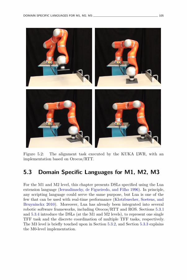
DOMAIN SPECIFIC LANGUAGES FOR M1, M2, M3 105
Figure 5.2: The alignment task executed by the KUKA LWR, with animplementation based on Orocos/RTT.
5.3 Domain Specific Languages for M1, M2, M3
For the M1 and M2 level, this chapter presents DSLs specified using the Luaextension language (Ierusalimschy, de Figueiredo, and Filho 1996). In principle,any scripting language could serve the same purpose, but Lua is one of thefew that can be used with real-time performance (Klotzbuecher, Soetens, andBruyninckx 2010). Moreover, Lua has already been integrated into severalrobotic software frameworks, including Orocos/RTT and ROS. Sections 5.3.1and 5.3.4 introduce the DSLs (at the M1 and M2 levels), to represent one singleTFF task and the discrete coordination of multiple TFF tasks, respectively.The M3 level is briefly touched upon in Section 5.3.2, and Section 5.3.3 explainsthe M0-level implementation.

106 REUSABLE MOTION SPECIFICATIONS WITH EXECUTABLE DSL
Figure 5.3: The alignment task executed by the PR2, with an implementationbased on Orocos/RTT and ROS.
5.3.1 M1- and M2-level TFF-DSLs
At the M2 level, the TFF-DSL defines a template for each type of hybridforce/velocity controlled TFF specification. For example, move_down movesthe end effector downwards with a constant velocity, or push_down appliesa force downwards with the other directions force-controlled and set to zero.compliant_slide_x controls the arm to move in the x-direction while applyinga force downwards. The DSL follows very straightforwardly from the descriptionsin (Bruyninckx and De Schutter 1996); the following listing shows three sampleTFF-DSL specifications:
push_down = motion_spec :new {xt= ax_spec :new{ type='force ', value =0, unit='N' },yt= ax_spec :new{ type='force ', value =0, unit='N' },zt= ax_spec :new{ type='force ', value =10 , unit='N' },axt= ax_spec :new{ type='force ', value =0, unit='Nm ' },ayt= ax_spec :new{ type='force ', value =0, unit='Nm ' },azt= ax_spec :new{ type='force ', value =0, unit='Nm ' }
}
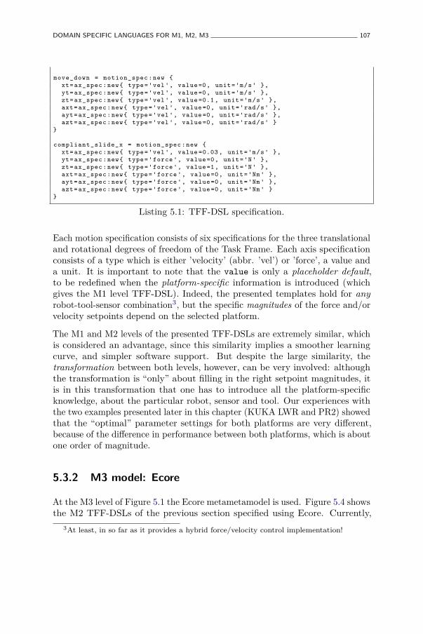
DOMAIN SPECIFIC LANGUAGES FOR M1, M2, M3 107
move_down = motion_spec :new {xt= ax_spec :new{ type='vel ', value =0, unit='m/s' },yt= ax_spec :new{ type='vel ', value =0, unit='m/s' },zt= ax_spec :new{ type='vel ', value =0.1 , unit='m/s' },axt= ax_spec :new{ type='vel ', value =0, unit='rad/s' },ayt= ax_spec :new{ type='vel ', value =0, unit='rad/s' },azt= ax_spec :new{ type='vel ', value =0, unit='rad/s' }
}
compliant_slide_x = motion_spec :new {xt= ax_spec :new{ type='vel ', value =0.03 , unit='m/s' },yt= ax_spec :new{ type='force ', value =0, unit='N' },zt= ax_spec :new{ type='force ', value =1, unit='N' },axt= ax_spec :new{ type='force ', value =0, unit='Nm ' },ayt= ax_spec :new{ type='force ', value =0, unit='Nm ' },azt= ax_spec :new{ type='force ', value =0, unit='Nm ' }
}
Listing 5.1: TFF-DSL specification.
Each motion specification consists of six specifications for the three translationaland rotational degrees of freedom of the Task Frame. Each axis specificationconsists of a type which is either ’velocity’ (abbr. ’vel’) or ’force’, a value anda unit. It is important to note that the value is only a placeholder default,to be redefined when the platform-specific information is introduced (whichgives the M1 level TFF-DSL). Indeed, the presented templates hold for anyrobot-tool-sensor combination3, but the specific magnitudes of the force and/orvelocity setpoints depend on the selected platform.
The M1 and M2 levels of the presented TFF-DSLs are extremely similar, whichis considered an advantage, since this similarity implies a smoother learningcurve, and simpler software support. But despite the large similarity, thetransformation between both levels, however, can be very involved: althoughthe transformation is “only” about filling in the right setpoint magnitudes, itis in this transformation that one has to introduce all the platform-specificknowledge, about the particular robot, sensor and tool. Our experiences withthe two examples presented later in this chapter (KUKA LWR and PR2) showedthat the “optimal” parameter settings for both platforms are very different,because of the difference in performance between both platforms, which is aboutone order of magnitude.
5.3.2 M3 model: Ecore
At the M3 level of Figure 5.1 the Ecore metametamodel is used. Figure 5.4 showsthe M2 TFF-DSLs of the previous section specified using Ecore. Currently,
3At least, in so far as it provides a hybrid force/velocity control implementation!
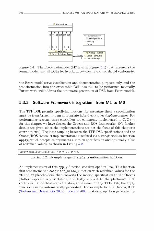
108 REUSABLE MOTION SPECIFICATIONS WITH EXECUTABLE DSL
MotionSpec
AxisSpec
type : AxisSpecType
<<enumeration>>AxisSpecType
velocityforce
AxisSpecValue
value : EDoubleunit : EString
xt
1
yt
1
zt
1
axt
1
ayt
1
azt
1
value
1
Figure 5.4: The Ecore metamodel (M2 level in Figure. 5.1) that represents theformal model that all DSLs for hybrid force/velocity control should conform-to.
the Ecore model serve visualization and documentation purposes only, and thetransformation into the executable DSL has still to be performed manually.Future work will address the automatic generation of DSL from Ecore models.
5.3.3 Software Framework integration: from M1 to M0
The TFF-DSL permits specifying motions; for executing these a specificationmust be transformed into an appropriate hybrid controller implementation. Forperformance reasons, these controllers are commonly implemented in C/C++;for this chapter we have chosen the Orocos and ROS frameworks. (No furtherdetails are given, since the implementations are not the focus of this chapter’scontributions.) The loose coupling between the TFF-DSL specifications and theOrocos/ROS controller implementations is realized via a transformation functionapply, which accepts as arguments a motion specification and optionally a listof redefined values, as shown in Listing 5.2.
apply ( compliant_slide_x , {xt =0.2 , zt =1})
Listing 5.2: Example usage of apply transformation function.
An implementation of this apply function was developed in Lua. This functionfirst transforms the compliant_slide_x motion with redefined values for thext and zt placeholders, then converts the motion specification to the Orocosplatform-specific representation, and lastly sends it to the platform’s TFFcontroller. Since these steps are always the same for any TFF-DSL, the applyfunction can be automatically generated. For example for the Orocos/RTT(Soetens and Bruyninckx 2005), (Soetens 2006) platform, apply is generated by

DOMAIN SPECIFIC LANGUAGES FOR M1, M2, M3 109
the following code:
function gen_apply (port)local rttms = rtt. Variable (" MotionSpec ")return function (ms , overrides )
set_rtt_ms (rttms , ms , overrides )port: write (ms)
endend
Listing 5.3: Generation of apply transformation function.
The gen_apply function generates a function which accepts a motionspecification and a list of default template values to override. This motionspecification is then written to the communication port which was passed as anargument to gen_apply.
5.3.4 Composing individual TFF-DSL motions into skills usingthe rFSM statechart DSL
After defining elementary motions, a rFSM Statechart (Chapter 4) is used tocompose these basic blocks into a robust skill (Smits 2010). The rFSM modelused is a lightweight Statechart variant designed for real-time coordination ofrobotic systems, and is as such suitable for this task. However, if required indifferent scenarios, any other behavioral model could be used instead. Therobustness is achieved by explicitly validating the outcome of motion executionsin the respective states and raising error events in case invalid conditions aredetected.4 The graphical model of this Statechart is shown in Figure 5.5.
The nominal behavior begins at the initial connector at the top left of thefigure and runs through the move_down, pre_align_z, align_z, pre_slide,compliant_slide_x and align_x states to the final connector at the bottom-left. Validation is performed in each state, and in case anomalies are detected,respective events are emitted. These events then trigger the transition tothe error connector, to which further error handling is connected. Thepre_align_z and pre_slide states serve to mitigate unstable behavior ofthe system during transitions. For instance, instead of immediately pushingdown with 20 N when entering in contact, pre_align_z prepares this transitionfor half a second by pushing down with 5 N.
In addition, the align skill in Figure 5.5 illustrates an advantage of usinghierarchical Statecharts instead of flat state automata: conflicts between
4The rFSM design, and the robustness aspects of its implementation, are beyond the scopeof this chapter.
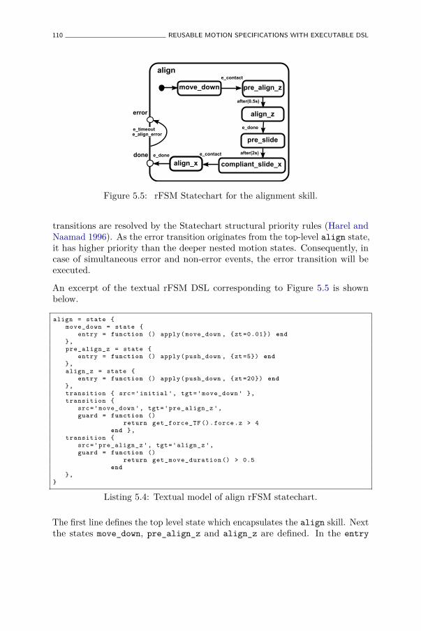
110 REUSABLE MOTION SPECIFICATIONS WITH EXECUTABLE DSL
align_z
move_down
compliant_slide_x
aligne_contact
e_done
align_xe_done
error
pre_align_z
pre_slide
e_contact
after(0.5s)
after(2s)done
e_align_errore_timeout
Figure 5.5: rFSM Statechart for the alignment skill.
transitions are resolved by the Statechart structural priority rules (Harel andNaamad 1996). As the error transition originates from the top-level align state,it has higher priority than the deeper nested motion states. Consequently, incase of simultaneous error and non-error events, the error transition will beexecuted.
An excerpt of the textual rFSM DSL corresponding to Figure 5.5 is shownbelow.
align = state {move_down = state {
entry = function () apply (move_down , {zt =0.01}) end},pre_align_z = state {
entry = function () apply (push_down , {zt =5}) end},align_z = state {
entry = function () apply (push_down , {zt =20}) end},transition { src='initial ', tgt='move_down ' },transition {
src='move_down ', tgt='pre_align_z ',guard = function ()
return get_force_TF (). force .z > 4end },
transition {src='pre_align_z ', tgt='align_z ',guard = function ()
return get_move_duration () > 0.5end
},}
Listing 5.4: Textual model of align rFSM statechart.
The first line defines the top level state which encapsulates the align skill. Nextthe states move_down, pre_align_z and align_z are defined. In the entry
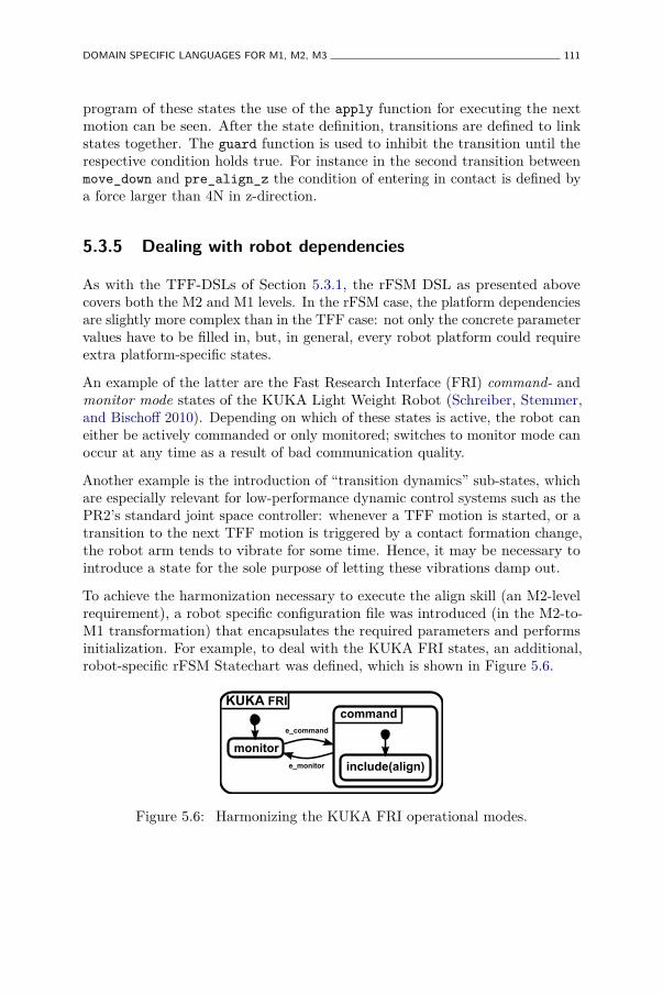
DOMAIN SPECIFIC LANGUAGES FOR M1, M2, M3 111
program of these states the use of the apply function for executing the nextmotion can be seen. After the state definition, transitions are defined to linkstates together. The guard function is used to inhibit the transition until therespective condition holds true. For instance in the second transition betweenmove_down and pre_align_z the condition of entering in contact is defined bya force larger than 4N in z-direction.
5.3.5 Dealing with robot dependencies
As with the TFF-DSLs of Section 5.3.1, the rFSM DSL as presented abovecovers both the M2 and M1 levels. In the rFSM case, the platform dependenciesare slightly more complex than in the TFF case: not only the concrete parametervalues have to be filled in, but, in general, every robot platform could requireextra platform-specific states.
An example of the latter are the Fast Research Interface (FRI) command- andmonitor mode states of the KUKA Light Weight Robot (Schreiber, Stemmer,and Bischoff 2010). Depending on which of these states is active, the robot caneither be actively commanded or only monitored; switches to monitor mode canoccur at any time as a result of bad communication quality.
Another example is the introduction of “transition dynamics” sub-states, whichare especially relevant for low-performance dynamic control systems such as thePR2’s standard joint space controller: whenever a TFF motion is started, or atransition to the next TFF motion is triggered by a contact formation change,the robot arm tends to vibrate for some time. Hence, it may be necessary tointroduce a state for the sole purpose of letting these vibrations damp out.
To achieve the harmonization necessary to execute the align skill (an M2-levelrequirement), a robot specific configuration file was introduced (in the M2-to-M1 transformation) that encapsulates the required parameters and performsinitialization. For example, to deal with the KUKA FRI states, an additional,robot-specific rFSM Statechart was defined, which is shown in Figure 5.6.
command
monitor
include(align)
KUKA FRI
e_monitor
e_command
Figure 5.6: Harmonizing the KUKA FRI operational modes.
112 REUSABLE MOTION SPECIFICATIONS WITH EXECUTABLE DSL
The Statechart models both FRI states and the connecting transitions whichare triggered by events raised by the low-level FRI controller. The robot-independent align Statechart is included into the FRI command state. Thisway it is guaranteed that the align statechart is only executed when the FRI isin command mode. If an unexpected switch to monitor mode occurs the alignskill will be exited cleanly. More importantly, the robot-independent behaviorremains agnostic of the FRI statechart and is not polluted with robot specificinformation.
As similar configuration file is used for the Willow Garage PR2. Since the PR2does not require specific operational states, the align statechart is executeddirectly.
5.4 Experiments on PR2 and KUKA LWR
The PR2’s two 7 DOF arms are passively backdrivable, making them verysuitable for manipulations tasks in contact with an environment. Due to thelack of a built-in force sensor, a JR3 force/torque sensor was added in the gripperof the PR2. The LWR is not passively backdrivable, but provides a controlledcompliance mode and force sensing via its internal joint torque sensors5.
Figure 5.7 shows measured forces, desired Cartesian velocities and gripper toolframe position and orientation of the alignment task over time for the PR2.The vertical black lines mark when a new statechart state was entered.
The plot of the measured forces clearly shows the benefit of the pre_align andpre_slide states in reducing unstable, oscillating behavior during switches ofmotion specifications. Although simple and effective, it is intended to replacethese (manually introduced) intermediate states by (automatically generated)transformation states, that blend two motion specifications within a given timeframe.
A plot of the task execution over time on the KUKA LWR is very similarto that on the PR2 and is hence omitted. A notable difference is that themeasured forces are much smoother on the LWR. On the one hand, this isexplained by the task being executed slower than on the PR2 (just to showthe influence of different platform-specific parameters). On the other hand, theLWR’s controller is much more performant that the PR2’s.
5The source code of these experiments is available here:https://github.com/kmarkus/tff_dsl_tests

EXPERIMENTS ON PR2 AND KUKA LWR 113
0 2 4 6 8 10 12 14 16 18t ime [s]
− 10
− 5
0
5
10
15
20
25
measu
redforces[N
]
move_d
own
pre
_align
align
pre
_slide_x
slide_x
align_x
xyz
0 2 4 6 8 10 12 14 16 18t ime [s]
− 1.5
− 1.0
− 0.5
0.0
0.5
1.0
desire
dcartesian
velocities[m
/s] x
yz
0 2 4 6 8 10 12 14 16 18t ime [s]
0.0
0.1
0.2
0.3
0.4
0.5
0.6
0.7
gripperto
olframe
translation[m
]
xyz
0 2 4 6 8 10 12 14 16 18t ime [s]
− 0.5
0.0
0.5
1.0
1.52.0
2.5
3.0
3.5
gripperto
olframe
orienta
tion[rad]
rollpit chyaw
Figure 5.7: Forces, velocities and positions of the PR2 robot.
Source code Lines of codeElementary TFF motions 60Alignment Skill rFSM Statechart 33Total 93
Table 5.1: Platform-independent code
Tables 5.1 and 5.2 summarize the lines of code for the various models. Theplatform-independent models required for the alignment skill consist roughlyof 100 lines of code. In order to execute these on one of either robots requiresapproximately an additional 200 lines, of which one half consists of softwareframework integration and the other of robot specific parameter or operationalmode related code. Although it would be desirable, it is unlikely that thesoftware framework code can be much reduced. In contrast it should be possibleto significantly reduce the manually developed robot specific code by generating
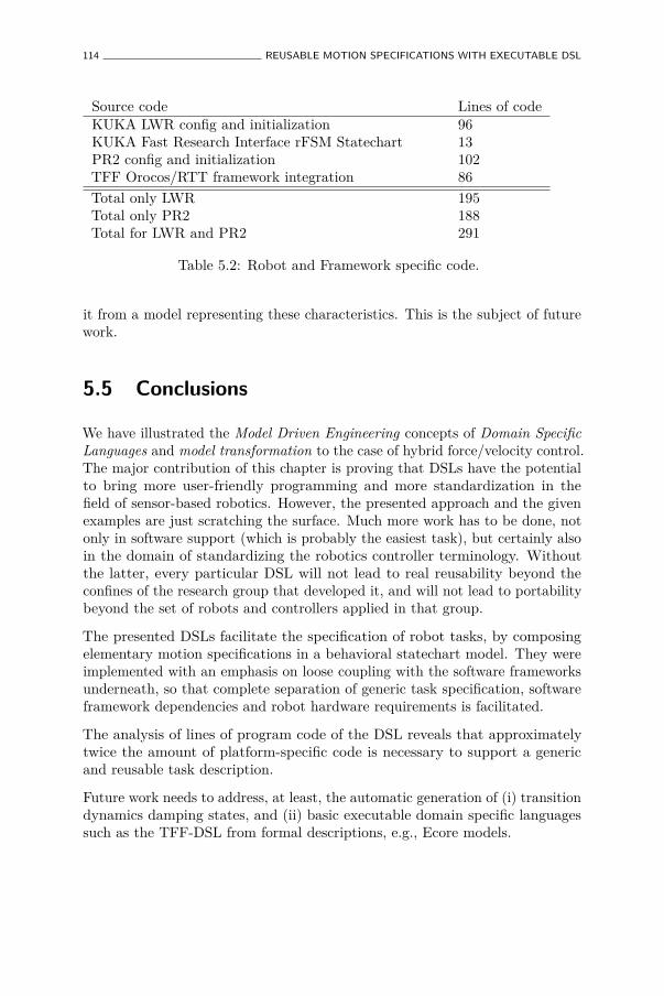
114 REUSABLE MOTION SPECIFICATIONS WITH EXECUTABLE DSL
Source code Lines of codeKUKA LWR config and initialization 96KUKA Fast Research Interface rFSM Statechart 13PR2 config and initialization 102TFF Orocos/RTT framework integration 86Total only LWR 195Total only PR2 188Total for LWR and PR2 291
Table 5.2: Robot and Framework specific code.
it from a model representing these characteristics. This is the subject of futurework.
5.5 Conclusions
We have illustrated the Model Driven Engineering concepts of Domain SpecificLanguages and model transformation to the case of hybrid force/velocity control.The major contribution of this chapter is proving that DSLs have the potentialto bring more user-friendly programming and more standardization in thefield of sensor-based robotics. However, the presented approach and the givenexamples are just scratching the surface. Much more work has to be done, notonly in software support (which is probably the easiest task), but certainly alsoin the domain of standardizing the robotics controller terminology. Withoutthe latter, every particular DSL will not lead to real reusability beyond theconfines of the research group that developed it, and will not lead to portabilitybeyond the set of robots and controllers applied in that group.
The presented DSLs facilitate the specification of robot tasks, by composingelementary motion specifications in a behavioral statechart model. They wereimplemented with an emphasis on loose coupling with the software frameworksunderneath, so that complete separation of generic task specification, softwareframework dependencies and robot hardware requirements is facilitated.
The analysis of lines of program code of the DSL reveals that approximatelytwice the amount of platform-specific code is necessary to support a genericand reusable task description.
Future work needs to address, at least, the automatic generation of (i) transitiondynamics damping states, and (ii) basic executable domain specific languagessuch as the TFF-DSL from formal descriptions, e.g., Ecore models.

Chapter 6
A Lightweight, ComposableMetamodeling Language forSpecification and Validationof Structural Constraints onInternal Domain SpecificLanguages∗
6.1 Abstract
This chapter describes a declarative and lightweight metamodeling frameworkcalled uMF for modeling and validating structural constraints on programminglanguage data-structures. By depending solely on the Lua language, uMF isembeddable even in very constrained embedded systems. That way, modelscan be instantiated and checked close to or even within the final run-timeenvironment, thus permitting validation to take the current state of the systeminto account. In contrast to classical metamodeling languages such as Ecore,
∗This chapter is based on Klotzbücher, M., and Bruyninckx, H. A lightweight, composablemetamodeling language for specification and validation of internal domain specific languages.In Proceedings of the 8th International Workshop on Model-based Methodologies for Pervasiveand Embedded Software (MOMPES’12), Germany, LNCS, 2012.
115

116 SPECIFYING AND VALIDATING INTERNAL DSL
uMF supports open world models that are only partially constrained. Weillustrate the use of uMF with a real-world example of a robot control formalismand compare it with a previously hand-written implementation. The resultsindicate that strict formalization was facilitated while flexibility and readabilityof the constraints were improved.
6.2 Introduction
A domain specific language (DSL) is built specifically to express the concepts ofa particular domain. Generally, two types of DSL can be distinguished accordingto the underlying implementation strategy. An external DSL is constructedfrom scratch, starting from definition of the desired syntax to implementationof the associated parser for reading it. In contrast, internal or embedded DSLare constructed on top of an existing host language (Fowler 2005) (Spinellis2001). While this technique has been used for decades, in particular by the Lispand Scheme communities, it has recently gained popularity through dynamiclanguages such as Ruby. Internal DSL offer some advantages over external ones.Firstly, existing infrastructure provided by the host language can be reused.Secondly, embedded DSL models can be typically loaded/instantiated withinthe host language without any parsing effort on the side of the DSL developer.Thirdly, when internal DSL are specified in a data-oriented manner (as proposedin this chapter) models can easily be introspected and interpreted at runtime.On the downside, as models are specified using the host language (or a subsetthereof), the syntax of an internal DSL is always constrained by the syntax ofthe host language.
As an internal DSL reuses the parsing infrastructure of its host language, basicsyntax checking and error reporting is taken care of automatically. Using OMGMDA terminology, the host language can thus be seen as the M2 (meta-) modelto which the M1 model must conform-to (Bézivin 2005).
Obviously, this conformance relationship constrains any real-world DSL toolittle, hence additional checking is necessary to validate conformity with theconcepts of the domain. For internal DSL, this is mostly achieved by manualprogramming the validation, which is a tedious and error prone task.
Consider a DSL for modeling 3D vectors. If object oriented concepts aresupported by the host language, the obvious choice would be to define a classand use its constructor to set and validate the attributes. We would like to avoidthis approach for two reasons. Firstly, it still requires implementing manualvalidation in the constructor. Secondly, most object oriented programming(OOP) models typically close the world for the model, meaning that additional

INTRODUCTION 117
attributes are prohibited. Our goal is to avoid this implicit closing for tworeasons: firstly, explicitly permitting additional attributes in addition to theknown enables implementing plugins that extend the behavior of the defaultmodel. As an example, the vector could be extended with physical units tobe used for validation in arithmetic operations. Secondly, open models permitvalidating a single model against multiple specifications, of which each validatesone aspect of the model. An example for this is given in Section 6.4.1.
Lastly, open models enable development of DSL in a more natural order: insteadof starting by specifying the metamodel and only then defining and testingmodels, this approach permits to start by defining concrete models, and onlylater to add structural constraints when the underlying metamodel is becomingapparent.
As an alternative to the class based specification of 3D vectors, Listing 6.1 showsthe use of a simple associative array. This alternative seems likewise complexto validate, as it requires asserting that the fields x, y and z are defined and ofcorrect type. If the type is defined to be closed, the absence of any other fieldsmust be checked. Moreover, if optionality of entries is supported, it must beasserted that all non-optional fields are defined.
v1 = { x=1, y=0, z=0 }
Listing 6.1: 3D vector model specified using a Lua table
To overcome these limitations we propose a declarative, constraint specificationDSL, that is part of a minimalistic Lua (Ierusalimschy, de Figueiredo, andFilho 1996) framework called uMF (micro modeling framework). uMF permitsspecifying and validating the structure of Lua data types and is complementedby a mechanism for declaring typed arrays. While in principle most dynamicprogramming languages could have been used, Lua has some benefits for buildingembedded DSL that are described below.
6.2.1 Internal DSL in Lua
The Lua language is an extremly lightweight1, yet multi-paradigm scriptinglanguage whose semantics are strongly influenced by the Scheme dialect of Lisp.Amongst others, this is revealed in the composite table data structure (the analogto Lisp’s list), that apart from behaving as a list ({1,2,3}) can also function asan associative array ({x=1, y=2}) or even as both simultaneously ({x=1, y=2,1, 2, 3}. Tables are the key mechanism for constructing embedded Lua DSLthat yield an intuitive syntax as shown in the examples.
1approximately 250K for the complete library.
118 SPECIFYING AND VALIDATING INTERNAL DSL
In Lua, OOP is typically implemented using metatables. In a nutshell,metatables permit refining the behavior of regular tables by redefining itsstandard operations such as indexing of fields, assigning new values to fields orinvocation of a table. Using this mechanism, sophisticated OOP models havebeen realized. As uMF is primarily used to model constraints on data-structures,it does not strictly require OOP concepts. Nevertheless we use a minimalisticclass model for introducing the notion of typed Lua tables, but which are bydefault agnostic about the data they contain. Further information on Lua canbe found in the language reference manual (Ierusalimschy, de Figueiredo, andCeles 2012).
6.2.2 Related work
Most metamodeling today is focused on so called language workbenches thatprovide tooling for development of external DSL. An overview of these can befound here (Merkle 2010).
MOF (Object Management Group 2006) is the OMG modeling language forspecifying metamodels, which can further be annotated with OCL constraints(Object Management Group a). The most widely used implementation of MOFis Ecore of the Eclipse EMF project (Eclipse Foundation b). Xtext is a languageframework integrated with Ecore that supports generating external DSL andassociative editors for their specification. Although these tools are only looselycoupled with Eclipse, they still inherently depend on the Java language, whichconstrains their application for small embedded systems.
The idea of describing entities of a programming language is not new. Bezivin(Bézivin 2005) points out the importance of distinguishing between the tworelationships instance-of of OOP and conforms-to of MDE. Magritte (Renggli,Ducasse, and Kuhn 2007) is a meta-description framework that is tightlyintegrated into the Smalltalk object model. Magritte permits annotatingSmalltalk object with metadata than can then be used for various purposes suchas for creating views or editors, validation, and persistence. Like uMF the hostlanguage itself is used to specify additional constraints. The main difference isthat uMF constraints are defined on data (opposed to objects) and that uMFis stronger focused on embeddability in contrast to dynamic web development.
XSD (XML Schema Definition) (W3C 2001) is a language for defining thestructure of XML documents to permit their validation. Unlike uMF’s Luasyntax, XSD is XML based and thus not particularly well suited for textualmodeling by humans. Moreover, our approach is easily embedded by onlydepending on the minimal Lua language opposed to the rather heavyweightXML host language. An alternative approach is suggested by Renggli et al.
THE UMF MICRO-MODELING FRAMEWORK 119
(Renggli, Ducasse, Gîrba, and Nierstrasz 2010) who observe the insufficiency oftraditional static code analysis tools when applied to internal DSL. To take intoaccount the specifics of the latter, the authors describe an approach of addingadditional rules to check for common errors.
6.3 The uMF micro-modeling framework
This section gives an overview of uMF, which can be divided into two parts:types and structural specifications. The uMF source code is available here(Klotzbuecher 2012).
6.3.1 uMF Types
To attach type to Lua tables, uMF provides a minimalistic OOP model. Usingtyped tables facilitates both modeling and validation; The first because itpermits a more explicit syntax to be used (e.g. Vector{x=...} instead of only{x=...}) and the latter because a type mismatch error is typically much clearerthan an error reporting structural discrepancies. As a side effect of introducingan OOP model, single inheritance and virtual methods can be used to definepretty printing methods or constructors. The whole OO system consists only ofapproximately 60 lines of Lua2.
6.3.2 uMF Specs
The core of uMF consists of the specification infrastructure which amountsto approximately 230 LOC. Using this, the (desired) structure of data canbe defined by using so called specs. Specs describe primitive data (strings,numbers, booleans, enums, etc) or composite data (tables or extended types).Specs reflect the compositionality of the data they describe, hence a TableSpecmay, analog to tables, contain primitive or composite data while primitive specsmay not contain any sub-specs. Definition of new specs is straightforward andencouraged.
As Lua tables can function as both list and associative array (consequentlyreferred to as array and dictionary), both parts are defined independently.
The spec for modeling a 3D vector using x, y, z fields is show in Listing 6.2.2Code lines only. Calculated using the cloc(1) tool.
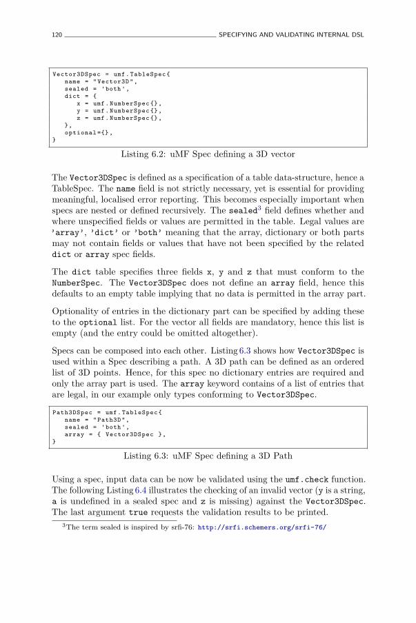
120 SPECIFYING AND VALIDATING INTERNAL DSL
Vector3DSpec = umf. TableSpec {name = " Vector3D ",sealed = 'both ',dict = {
x = umf. NumberSpec {},y = umf. NumberSpec {},z = umf. NumberSpec {},
},optional ={} ,
}
Listing 6.2: uMF Spec defining a 3D vector
The Vector3DSpec is defined as a specification of a table data-structure, hence aTableSpec. The name field is not strictly necessary, yet is essential for providingmeaningful, localised error reporting. This becomes especially important whenspecs are nested or defined recursively. The sealed3 field defines whether andwhere unspecified fields or values are permitted in the table. Legal values are’array’, ’dict’ or ’both’ meaning that the array, dictionary or both partsmay not contain fields or values that have not been specified by the relateddict or array spec fields.
The dict table specifies three fields x, y and z that must conform to theNumberSpec. The Vector3DSpec does not define an array field, hence thisdefaults to an empty table implying that no data is permitted in the array part.
Optionality of entries in the dictionary part can be specified by adding theseto the optional list. For the vector all fields are mandatory, hence this list isempty (and the entry could be omitted altogether).
Specs can be composed into each other. Listing 6.3 shows how Vector3DSpec isused within a Spec describing a path. A 3D path can be defined as an orderedlist of 3D points. Hence, for this spec no dictionary entries are required andonly the array part is used. The array keyword contains of a list of entries thatare legal, in our example only types conforming to Vector3DSpec.
Path3DSpec = umf. TableSpec {name = " Path3D ",sealed = 'both ',array = { Vector3DSpec },
}
Listing 6.3: uMF Spec defining a 3D Path
Using a spec, input data can be now be validated using the umf.check function.The following Listing 6.4 illustrates the checking of an invalid vector (y is a string,a is undefined in a sealed spec and z is missing) against the Vector3DSpec.The last argument true requests the validation results to be printed.
3The term sealed is inspired by srfi-76: http://srfi.schemers.org/srfi-76/
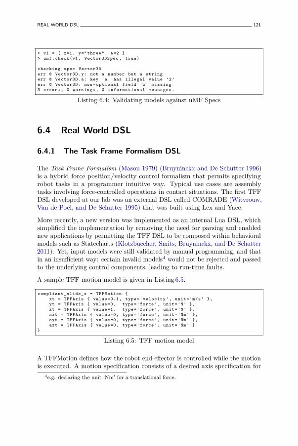
REAL WORLD DSL 121
> v1 = { x=1, y=" three ", a=2 }> umf. check (v1 , Vector3DSpec , true)
checking spec Vector3Derr @ Vector3D .y: not a number but a stringerr @ Vector3D .a: key 'a' has illegal value '2'err @ Vector3D : non - optional field 'z' missing3 errors , 0 warnings , 0 informational messages .
Listing 6.4: Validating models against uMF Specs
6.4 Real World DSL
6.4.1 The Task Frame Formalism DSL
The Task Frame Formalism (Mason 1979) (Bruyninckx and De Schutter 1996)is a hybrid force position/velocity control formalism that permits specifyingrobot tasks in a programmer intuitive way. Typical use cases are assemblytasks involving force-controlled operations in contact situations. The first TFFDSL developed at our lab was an external DSL called COMRADE (Witvrouw,Van de Poel, and De Schutter 1995) that was built using Lex and Yacc.
More recently, a new version was implemented as an internal Lua DSL, whichsimplified the implementation by removing the need for parsing and enablednew applications by permitting the TFF DSL to be composed within behavioralmodels such as Statecharts (Klotzbuecher, Smits, Bruyninckx, and De Schutter2011). Yet, input models were still validated by manual programming, and thatin an insufficient way: certain invalid models4 would not be rejected and passedto the underlying control components, leading to run-time faults.
A sample TFF motion model is given in Listing 6.5.
compliant_slide_x = TFFMotion {xt = TFFAxis { value =0.1 , type='velocity ', unit='m/s' },yt = TFFAxis { value =0, type='force ', unit='N' },zt = TFFAxis { value =1, type='force ', unit='N' },axt = TFFAxis { value =0, type='force ', unit='Nm ' },ayt = TFFAxis { value =0, type='force ', unit='Nm ' },azt = TFFAxis { value =0, type='force ', unit='Nm ' }
}
Listing 6.5: TFF motion model
A TFFMotion defines how the robot end-effector is controlled while the motionis executed. A motion specification consists of a desired axis specification for
4e.g. declaring the unit ’Nm’ for a translational force.
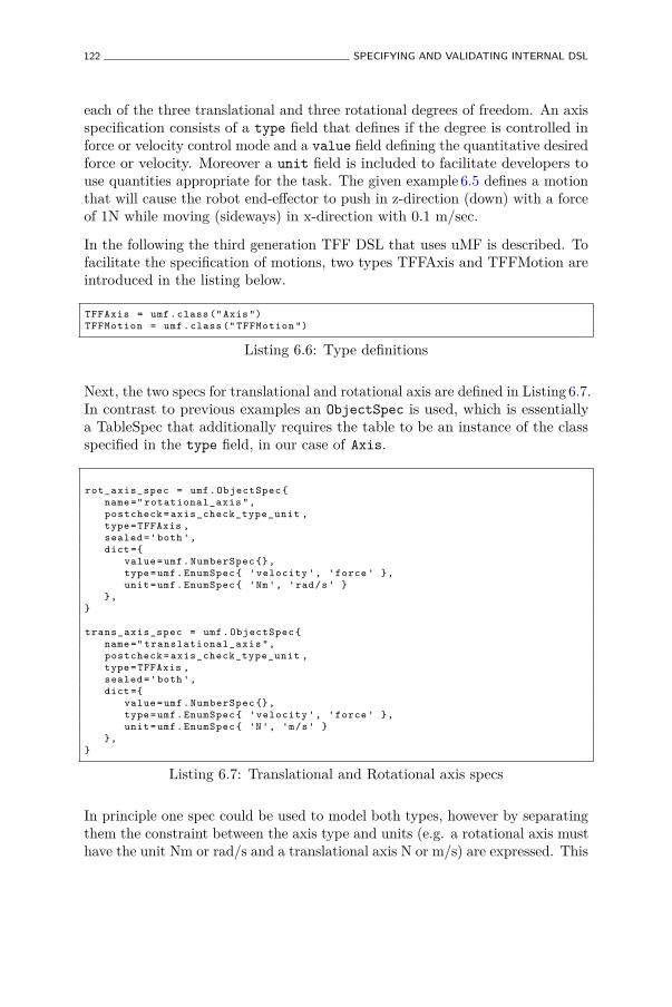
122 SPECIFYING AND VALIDATING INTERNAL DSL
each of the three translational and three rotational degrees of freedom. An axisspecification consists of a type field that defines if the degree is controlled inforce or velocity control mode and a value field defining the quantitative desiredforce or velocity. Moreover a unit field is included to facilitate developers touse quantities appropriate for the task. The given example 6.5 defines a motionthat will cause the robot end-effector to push in z-direction (down) with a forceof 1N while moving (sideways) in x-direction with 0.1 m/sec.
In the following the third generation TFF DSL that uses uMF is described. Tofacilitate the specification of motions, two types TFFAxis and TFFMotion areintroduced in the listing below.
TFFAxis = umf. class (" Axis ")TFFMotion = umf. class (" TFFMotion ")
Listing 6.6: Type definitions
Next, the two specs for translational and rotational axis are defined in Listing 6.7.In contrast to previous examples an ObjectSpec is used, which is essentiallya TableSpec that additionally requires the table to be an instance of the classspecified in the type field, in our case of Axis.
rot_axis_spec = umf. ObjectSpec {name =" rotational_axis ",postcheck = axis_check_type_unit ,type=TFFAxis ,sealed ='both ',dict ={
value =umf. NumberSpec {},type=umf. EnumSpec { 'velocity ', 'force ' },unit=umf. EnumSpec { 'Nm ', 'rad/s' }
},}
trans_axis_spec = umf. ObjectSpec {name =" translational_axis ",postcheck = axis_check_type_unit ,type=TFFAxis ,sealed ='both ',dict ={
value =umf. NumberSpec {},type=umf. EnumSpec { 'velocity ', 'force ' },unit=umf. EnumSpec { 'N', 'm/s' }
},}
Listing 6.7: Translational and Rotational axis specs
In principle one spec could be used to model both types, however by separatingthem the constraint between the axis type and units (e.g. a rotational axis musthave the unit Nm or rad/s and a translational axis N or m/s) are expressed. This
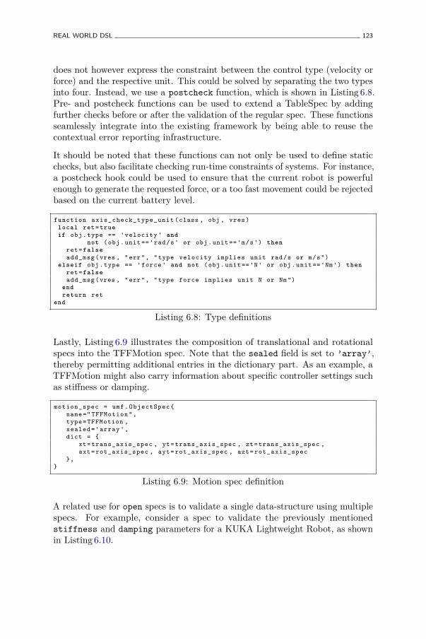
REAL WORLD DSL 123
does not however express the constraint between the control type (velocity orforce) and the respective unit. This could be solved by separating the two typesinto four. Instead, we use a postcheck function, which is shown in Listing 6.8.Pre- and postcheck functions can be used to extend a TableSpec by addingfurther checks before or after the validation of the regular spec. These functionsseamlessly integrate into the existing framework by being able to reuse thecontextual error reporting infrastructure.
It should be noted that these functions can not only be used to define staticchecks, but also facilitate checking run-time constraints of systems. For instance,a postcheck hook could be used to ensure that the current robot is powerfulenough to generate the requested force, or a too fast movement could be rejectedbased on the current battery level.
function axis_check_type_unit (class , obj , vres)local ret= trueif obj.type == 'velocity ' and
not (obj.unit == 'rad/s' or obj.unit == 'm/s') thenret= falseadd_msg (vres , "err", "type velocity implies unit rad/s or m/s")
elseif obj.type == 'force ' and not (obj.unit == 'N' or obj.unit == 'Nm ') thenret= falseadd_msg (vres , "err", "type force implies unit N or Nm ")
endreturn ret
end
Listing 6.8: Type definitions
Lastly, Listing 6.9 illustrates the composition of translational and rotationalspecs into the TFFMotion spec. Note that the sealed field is set to ’array’,thereby permitting additional entries in the dictionary part. As an example, aTFFMotion might also carry information about specific controller settings suchas stiffness or damping.
motion_spec = umf. ObjectSpec {name =" TFFMotion ",type=TFFMotion ,sealed ='array ',dict = {
xt= trans_axis_spec , yt= trans_axis_spec , zt= trans_axis_spec ,axt= rot_axis_spec , ayt= rot_axis_spec , azt= rot_axis_spec
},}
Listing 6.9: Motion spec definition
A related use for open specs is to validate a single data-structure using multiplespecs. For example, consider a spec to validate the previously mentionedstiffness and damping parameters for a KUKA Lightweight Robot, as shownin Listing 6.10.
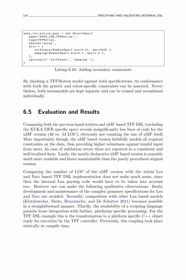
124 SPECIFYING AND VALIDATING INTERNAL DSL
kuka_lwr_motion_spec = umf. ObjectSpec {name =" KUKA_LWR_TFFMotion ",type=TFFMotion ,sealed ='array ',dict = {
stiffness = NumberSpec { min =0.01 , max =5000 },damping = NumberSpec { min =0.1 , max =1.0 },
},optional ={ 'stiffness ', 'damping ' },
}
Listing 6.10: Adding secondary constraints
By checking a TFFMotion model against both specifications, its conformancewith both the generic and robot-specific constraints can be asserted. Never-theless, both metamodels are kept separate and can be reused and recombinedindividually.
6.5 Evaluation and Results
Comparing both the previous hand-written and uMF based TFF DSL (excludingthe KUKA LWR specific spec) reveals insignificantly less lines of code for theuMF version (46 vs. 53 LOC), obviously not counting the size of uMF itself.More importantly though, the uMF based version faithfully models all requiredconstraints on the data, thus providing higher robustness against invalid inputfrom users. In case of validation errors these are reported in a consistent andwell-localized form. Lastly, the mostly declarative uMF based version is arguablymuch more readable and hence maintainable than the purely procedural originalversion.
Comparing the number of LOC of the uMF version with the initial Lexand Yacc based TFF DSL implementation does not make much sense, sincethen the internal Lua parsing code would have to be taken into accounttoo. However one can make the following qualitative observations: firstly,development and maintenance of the complex grammer specifications for Lexand Yacc are avoided. Secondly, composition with other Lua based models(Klotzbuecher, Smits, Bruyninckx, and De Schutter 2011) becomes possiblein a straightforward manner. Thirdly, the availability of a scripting languagepermits loose integration with further, platforms specific processing. For theTFF DSL example this is the transformation to a platform specific C++ objectready for execution by the TFF controller. Previously, this coupling took placestatically at compile time.
CONCLUSION AND OUTLOOK 125
6.5.1 The limits of untyped conforms-to
The following limitation was observed regarding the use of purely structuralconstraints, e.g. untyped tables in uMF. Consider the example in Listing 6.11that extends the previously shown 3DPathSpec to permit a path to be formedby both 3D and 6D vectors, that are described using untyped TableSpecs.
PathSpec = TableSpec {name = "Path",sealed = 'both ',array = { Vector3DSpec , Vector6DSpec },
}
Listing 6.11: Example of difficult to validate purely structural model
To validate a vector entry of a concrete path, this entry needs to be checkedagainst each array spec (Vector3DSpec and Vector6DSpec) until a spec thatsuccessfully validates the entry is found. The problem is that if all checks fail,it becomes impossible to provide a concise error message, since uMF can notknow the TableSpec against which validation should have succeeded. Sincethis is an inherent problem of the pure, untyped conforms-to relationship, theonly solution is to print the errors of all checks, which is not user friendly andverbose. The problem is worsened if the PathSpec array is unsealed, as in thatcase it is impossible to know if this is an error at all. On the other hand theseproblems can be avoided altogether by using typed tables when disjunctivematching of multiple specs takes place.
6.6 Conclusion and Outlook
We have presented a lightweight, declarative DSL for specifying structural andcomposable constraints on data-structure of the Lua language. This meta-DSLcan be easily extended and integrated into a runtime environment by usingadditional hooks. Using the Lua language yields a syntax that is reasonablyunderstandable to humans and moreover permits the DSL to be deployed intovery constrained embedded systems, such as robot or machine tool control panels.Since open uMF specs can be used to specify partial conformance constraintson data, it becomes possible to use multiple specs to validate different aspectsof a single model, thereby essentially permitting virtual constraint composition.
Currently, the main use of uMF specs is to validate user models and provideindicative error messages, however further uses such as view generation or modelpersistence are conceivable. This could be achieved by extending specs to carryadditional meta-data, such as which fields shall be displayed or persisted.
126 SPECIFYING AND VALIDATING INTERNAL DSL
Furthermore, we plan to loosen the currently tight coupling to the Lua languageby providing a horizontal, heterogeneous transformation (Mens and Van Gorp2006) of spec and model files to the JSON (Crockford 2006) format. An exampleof this using the Vector3DSpec showed earlier is given in Listing 6.12.
{"name": " Vector3D "" sealed ": "both","dict": {
"y": " NumberSpec ","x": " NumberSpec ","z": " NumberSpec ",
}," optional ": {},
}
Listing 6.12: Vector3DSpec represented in JSON
Assuming the absence of functions in the model (such as pre- and postcheckhooks) the transformation to JSON can be trivially implemented in a bi-directional manner. When permitting functions, the transformation from JSONto Lua is still feasible by representing functions as strings that are evaluated afterthe transformation. Providing an alternative, Lua independent input syntaxwould permit uMF to be used as a lightweight, standalone model checker.

Chapter 7
Pure Coordination using theCoordinator–ConfiguratorPattern∗
7.1 Abstract
We report on our efforts to improve different aspects of coordination incomplex, component-based robotic systems. Coordination is a system levelaspect concerned with commanding, configuring and monitoring functionalcomputations such that the system as a whole behaves as desired. To that enda variety of models such as Petri-nets or Finite State Machines may be utilized.These models specify actions to be executed, such as invoking operations orconfiguring components to achieve a certain goal.
This traditional approach has several disadvantages related to loss of reusabilityof coordination models due to coupling with platform-specific functionality, non-deterministic temporal behavior and limited robustness as a result of executingplatform operations within the context of the coordinator.
To avoid these shortcomings, we propose to split this “rich” coordinator intoa Pure Coordinator and a Configurator. Although the coordinator remains in
∗This chapter is based on Klotzbücher, M., Biggs, G., and Bruyninckx, H. PureCoordination using the Coordinator–Configurator Pattern. In Proceedings of the 3rdInternational Workshop on Domain-Specific Languages and models for ROBotic systems(DSLRob-12). SIMPAR 2012. Tsukuba, Japan (November 2012).
127
128 PURE COORDINATION USING THE COORDINATOR–CONFIGURATOR PATTERN
charge of commanding and reacting, the execution of actions is deferred to theConfigurator. This pattern, called Coordinator–Configurator, is implementedas a novel Configurator domain specific language that can be used togetherwith any model of coordination. We illustrate the approach by refactoring anexisting application that realizes a safe haptic coupling of two youBot mobilemanipulators.
7.2 Introduction
The context of this work (and hence also for the described pattern) is complex,component-based robotics and machine tool systems operating under real-time constraints. For building such systems, an increasingly acknowledged bestpractice is to separate the concerns of Coordination, Computation, Configurationand Communication (Radestock and Eisenbach 1996; Prassler, Bruyninckx,Nilsson, and Shakhimardanov 2009).
Computation defines the basic, functional building blocks from which a systemis constructed. Communication defines how and with whom the individualelements of a system communicate. Configuration defines the properties of asystem . Lastly, Coordination is concerned with supervising and monitoringthe computations in way that the system as a whole behaves as intended.
Classical coordination models that have been used in robotics are Petri-Nets(Rosell 2004), Finite State Machines (FSM) (Finkemeyer, Kröger, and Wahl2005) and Statecharts (Marty, Sahraoui, and Sartor 1998; Klotzbuecher, Smits,Bruyninckx, and De Schutter 2011). These models are used to define whencertain behaviors shall be executed. For instance, UML state machines (ObjectManagement Group 2011) allow execution of a behavior upon entering or exitinga state. The exact actions available depend on the primitives of the underlyingframework, and may include invoking operations or modifying the configurationof a component.
This traditional approach has three major disadvantages. Firstly, reusabilityof coordination models is reduced because the model is polluted with platformspecific information. In other words, reusing the same model on a different robotor software framework requires intrusive refactoring to replace the platformspecific operations used in the coordinator. Secondly, the blocking invocation ofoperations on functional computations can severely degrade the determinism ofthe Coordinator. Lastly, Coordinator robustness is reduced since an invocationmight block indefinitely or crash, either of which may effectively render thecoordinator inoperative.
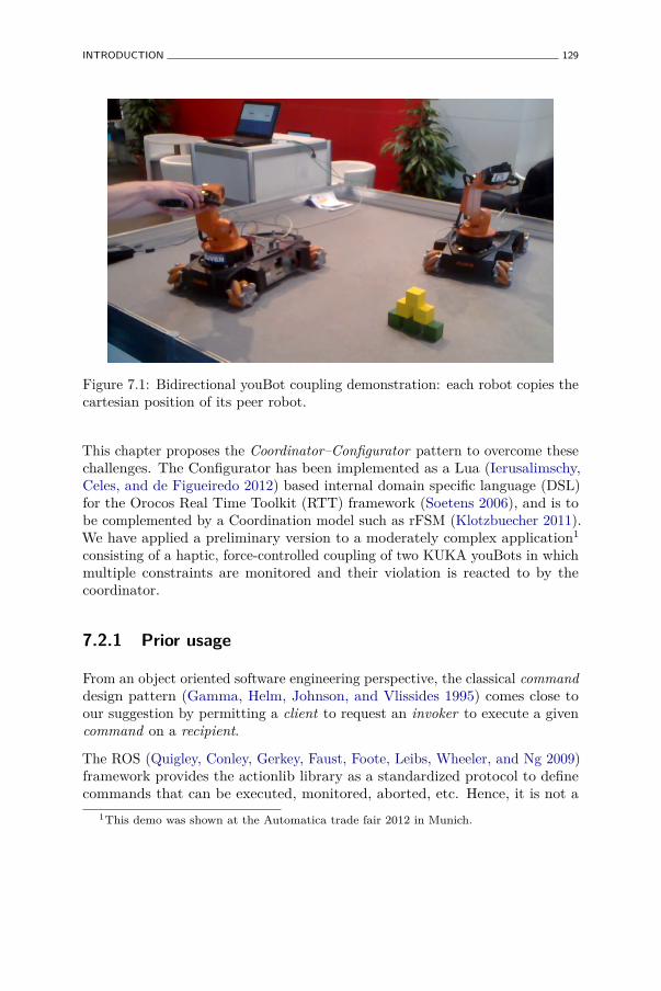
INTRODUCTION 129
Figure 7.1: Bidirectional youBot coupling demonstration: each robot copies thecartesian position of its peer robot.
This chapter proposes the Coordinator–Configurator pattern to overcome thesechallenges. The Configurator has been implemented as a Lua (Ierusalimschy,Celes, and de Figueiredo 2012) based internal domain specific language (DSL)for the Orocos Real Time Toolkit (RTT) framework (Soetens 2006), and is tobe complemented by a Coordination model such as rFSM (Klotzbuecher 2011).We have applied a preliminary version to a moderately complex application1
consisting of a haptic, force-controlled coupling of two KUKA youBots in whichmultiple constraints are monitored and their violation is reacted to by thecoordinator.
7.2.1 Prior usage
From an object oriented software engineering perspective, the classical commanddesign pattern (Gamma, Helm, Johnson, and Vlissides 1995) comes close toour suggestion by permitting a client to request an invoker to execute a givencommand on a recipient.
The ROS (Quigley, Conley, Gerkey, Faust, Foote, Leibs, Wheeler, and Ng 2009)framework provides the actionlib library as a standardized protocol to definecommands that can be executed, monitored, aborted, etc. Hence, it is not a
1This demo was shown at the Automatica trade fair 2012 in Munich.
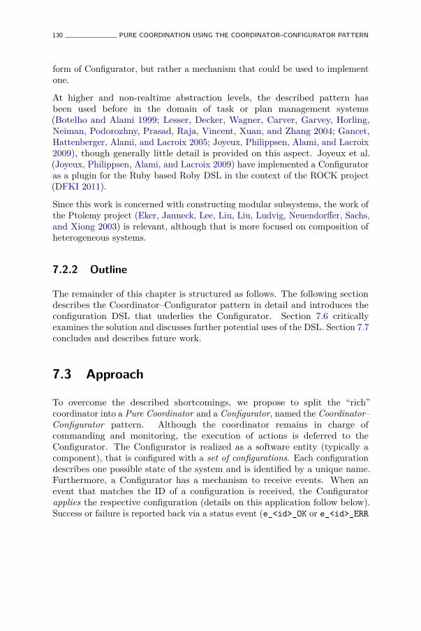
130 PURE COORDINATION USING THE COORDINATOR–CONFIGURATOR PATTERN
form of Configurator, but rather a mechanism that could be used to implementone.
At higher and non-realtime abstraction levels, the described pattern hasbeen used before in the domain of task or plan management systems(Botelho and Alami 1999; Lesser, Decker, Wagner, Carver, Garvey, Horling,Neiman, Podorozhny, Prasad, Raja, Vincent, Xuan, and Zhang 2004; Gancet,Hattenberger, Alami, and Lacroix 2005; Joyeux, Philippsen, Alami, and Lacroix2009), though generally little detail is provided on this aspect. Joyeux et al.(Joyeux, Philippsen, Alami, and Lacroix 2009) have implemented a Configuratoras a plugin for the Ruby based Roby DSL in the context of the ROCK project(DFKI 2011).
Since this work is concerned with constructing modular subsystems, the work ofthe Ptolemy project (Eker, Janneck, Lee, Liu, Liu, Ludvig, Neuendorffer, Sachs,and Xiong 2003) is relevant, although that is more focused on composition ofheterogeneous systems.
7.2.2 Outline
The remainder of this chapter is structured as follows. The following sectiondescribes the Coordinator–Configurator pattern in detail and introduces theconfiguration DSL that underlies the Configurator. Section 7.6 criticallyexamines the solution and discusses further potential uses of the DSL. Section 7.7concludes and describes future work.
7.3 Approach
To overcome the described shortcomings, we propose to split the “rich”coordinator into a Pure Coordinator and a Configurator, named the Coordinator–Configurator pattern. Although the coordinator remains in charge ofcommanding and monitoring, the execution of actions is deferred to theConfigurator. The Configurator is realized as a software entity (typically acomponent), that is configured with a set of configurations. Each configurationdescribes one possible state of the system and is identified by a unique name.Furthermore, a Configurator has a mechanism to receive events. When anevent that matches the ID of a configuration is received, the Configuratorapplies the respective configuration (details on this application follow below).Success or failure is reported back via a status event (e_<id>_OK or e_<id>_ERR
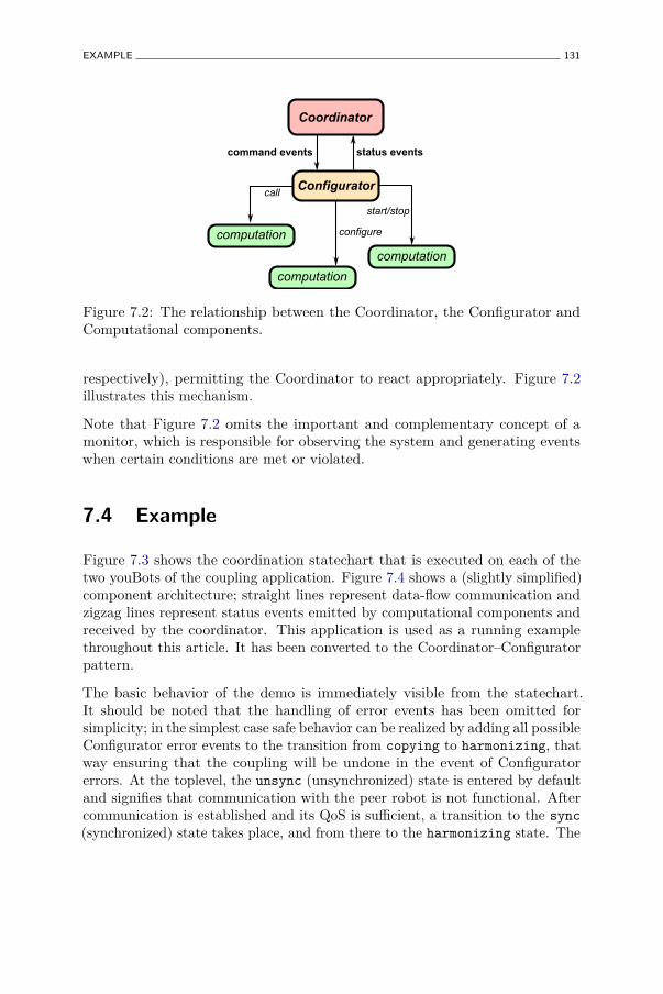
EXAMPLE 131
computation
computation
computation
Configurator
Coordinator
command events status events
start/stop
configure
call
Figure 7.2: The relationship between the Coordinator, the Configurator andComputational components.
respectively), permitting the Coordinator to react appropriately. Figure 7.2illustrates this mechanism.
Note that Figure 7.2 omits the important and complementary concept of amonitor, which is responsible for observing the system and generating eventswhen certain conditions are met or violated.
7.4 Example
Figure 7.3 shows the coordination statechart that is executed on each of thetwo youBots of the coupling application. Figure 7.4 shows a (slightly simplified)component architecture; straight lines represent data-flow communication andzigzag lines represent status events emitted by computational components andreceived by the coordinator. This application is used as a running examplethroughout this article. It has been converted to the Coordinator–Configuratorpattern.
The basic behavior of the demo is immediately visible from the statechart.It should be noted that the handling of error events has been omitted forsimplicity; in the simplest case safe behavior can be realized by adding all possibleConfigurator error events to the transition from copying to harmonizing, thatway ensuring that the coupling will be undone in the event of Configuratorerrors. At the toplevel, the unsync (unsynchronized) state is entered by defaultand signifies that communication with the peer robot is not functional. Aftercommunication is established and its QoS is sufficient, a transition to the sync(synchronized) state takes place, and from there to the harmonizing state. The

132 PURE COORDINATION USING THE COORDINATOR–CONFIGURATOR PATTERN
sync
copying
unsync
harmonizing
e_force_thres_exceeded
eight_DOF_mode
five_DOF_mode
e_five_DOF e_eight _DOF
e_force_thres_below
e_QoS_NOTOK e_QoS_OK
entry: ext_ref_mode(true)
exit: ext_ref_mode(false)
entry: 8DOF_mode()
entry: 5DOF_mode()
Figure 7.3: rFSM Coordination Statechart for the youBot coupling demo.

EXAMPLE 133
comm_mon
coordination_fsm
computation
Cart_Impedance
Dynamics
youbot_coupling
e_force_thres_exceeded/below
e_QoS_OKe_QoS_NOTOK
CartForceDes CartPosMsr
CartPosDsr
youbot_driver
JntForceDsr JntForceMsr
events
from CartPosMsr of peer Youbot
to CartPosDsrof peer Youbot
heartbeat_in
heartbeat_out
Figure 7.4: Component diagram illustrating the components and connectionsrunning on each of the youBots in the example.
latter means that the control loop responsible for moving the end-effector of therobot towards the position of the peer robot is operational and the impedancecontroller Cart_Impedance (see Figure 7.4) is computing a desired-force controlsignal. However, since this force is too high, this controller is configured to notoutput the signal but instead output a desired force of zero in all directions(ext_ref_mode(false)). As a result, the robot arm remains controlled in acompliant way, merely compensating for gravity. Only when both arms are(more or less) manually aligned by the operator does the desired force fallbeneath the threshold, and thus trigger the transition to the copying stateand from there (depending on the configuration) to the eight_DOF_mode orfive_DOF_mode. In either case, the coupling is put into effect by requestingthe controller to output the control signal ext_ref_mode(true). Switchingbetween the eight_DOF_mode and five_DOF_mode states is controlled by thehuman operator, and reconfigures the Dynamics component to use the holonomicbase as additional degrees of freedom or not. It should be noted that supportfor history connectors has not yet been implemented in rFSM; the identicalbehavior is realized by using additional transitions and guard conditions.
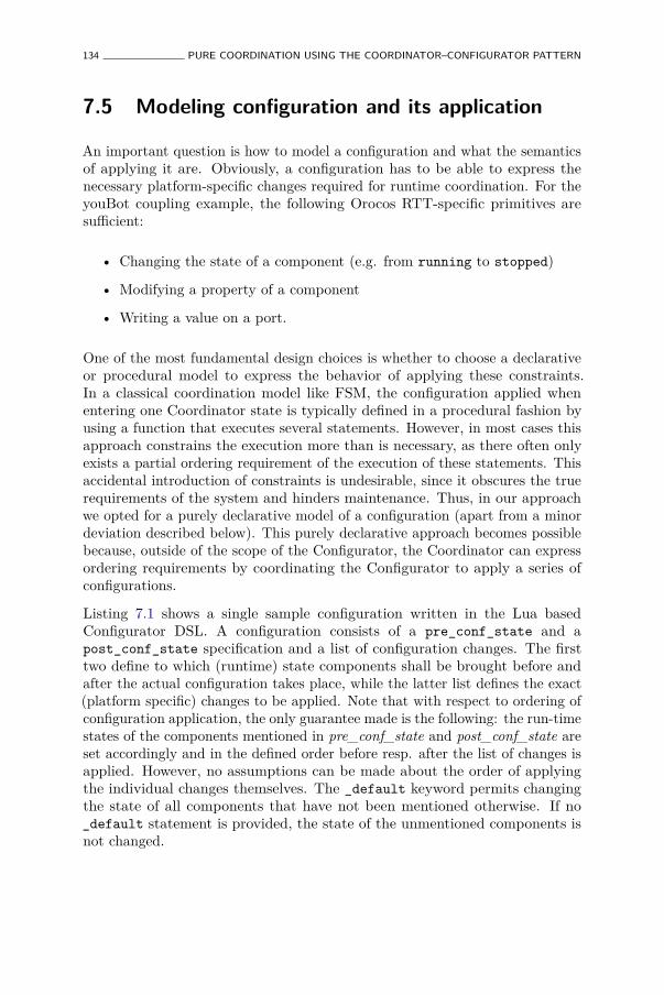
134 PURE COORDINATION USING THE COORDINATOR–CONFIGURATOR PATTERN
7.5 Modeling configuration and its application
An important question is how to model a configuration and what the semanticsof applying it are. Obviously, a configuration has to be able to express thenecessary platform-specific changes required for runtime coordination. For theyouBot coupling example, the following Orocos RTT-specific primitives aresufficient:
• Changing the state of a component (e.g. from running to stopped)
• Modifying a property of a component
• Writing a value on a port.
One of the most fundamental design choices is whether to choose a declarativeor procedural model to express the behavior of applying these constraints.In a classical coordination model like FSM, the configuration applied whenentering one Coordinator state is typically defined in a procedural fashion byusing a function that executes several statements. However, in most cases thisapproach constrains the execution more than is necessary, as there often onlyexists a partial ordering requirement of the execution of these statements. Thisaccidental introduction of constraints is undesirable, since it obscures the truerequirements of the system and hinders maintenance. Thus, in our approachwe opted for a purely declarative model of a configuration (apart from a minordeviation described below). This purely declarative approach becomes possiblebecause, outside of the scope of the Configurator, the Coordinator can expressordering requirements by coordinating the Configurator to apply a series ofconfigurations.
Listing 7.1 shows a single sample configuration written in the Lua basedConfigurator DSL. A configuration consists of a pre_conf_state and apost_conf_state specification and a list of configuration changes. The firsttwo define to which (runtime) state components shall be brought before andafter the actual configuration takes place, while the latter list defines the exact(platform specific) changes to be applied. Note that with respect to ordering ofconfiguration application, the only guarantee made is the following: the run-timestates of the components mentioned in pre_conf_state and post_conf_state areset accordingly and in the defined order before resp. after the list of changes isapplied. However, no assumptions can be made about the order of applyingthe individual changes themselves. The _default keyword permits changingthe state of all components that have not been mentioned otherwise. If no_default statement is provided, the state of the unmentioned components isnot changed.
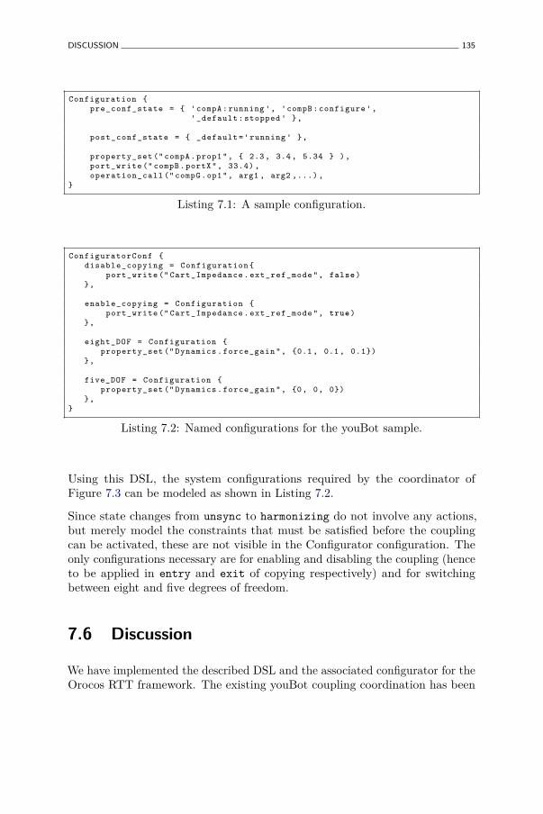
DISCUSSION 135
Configuration {pre_conf_state = { 'compA : running ', 'compB : configure ',
'_default : stopped ' },
post_conf_state = { _default ='running ' },
property_set (" compA . prop1 ", { 2.3 , 3.4 , 5.34 } ),port_write (" compB . portX ", 33.4) ,operation_call (" compG .op1", arg1 , arg2 ,...) ,
}
Listing 7.1: A sample configuration.
ConfiguratorConf {disable_copying = Configuration {
port_write (" Cart_Impedance . ext_ref_mode ", false )},
enable_copying = Configuration {port_write (" Cart_Impedance . ext_ref_mode ", true )
},
eight_DOF = Configuration {property_set (" Dynamics . force_gain ", {0.1 , 0.1 , 0.1})
},
five_DOF = Configuration {property_set (" Dynamics . force_gain ", {0, 0, 0})
},}
Listing 7.2: Named configurations for the youBot sample.
Using this DSL, the system configurations required by the coordinator ofFigure 7.3 can be modeled as shown in Listing 7.2.
Since state changes from unsync to harmonizing do not involve any actions,but merely model the constraints that must be satisfied before the couplingcan be activated, these are not visible in the Configurator configuration. Theonly configurations necessary are for enabling and disabling the coupling (henceto be applied in entry and exit of copying respectively) and for switchingbetween eight and five degrees of freedom.
7.6 Discussion
We have implemented the described DSL and the associated configurator for theOrocos RTT framework. The existing youBot coupling coordination has been
136 PURE COORDINATION USING THE COORDINATOR–CONFIGURATOR PATTERN
refactored to make use of the new Configurator. This approach has solved theshortcomings of the traditional approach: firstly, the coordination model remainsfree of any software platform-specific actions and can be reused with any otherframework, assuming a Configurator and corresponding configuration. Secondly,the actual changes are applied by the Configurator while the Coordinatorremains reactive and free to deal with any other situation that may arise. Lastly,failures within the Configurator are isolated from the Coordinator, permitting itto react to the absence of a status event and ultimately improving its robustness.Naturally, this robustness depends on the run-time context of both entities andthe worst-case failures possible.
Since the Configurator constitutes an additional level of indirection, the questionof the overhead introduced is justified. Obviously, this cannot be answered ingeneral but will mostly depend on the level of distribution between Coordinator,Configurator and configured components. Nevertheless, the Coordinator–Configurator pattern offers an advantage with respect to benchmarking andprofiling the Coordination behavior: since the execution of configurationapplication is localized within a single component, the respective measurementsneed likewise only to be added once. This avoids the scattering of profiling codeacross the Coordination model.
Lastly, having a flat map of configurations might be suboptimal in some cases, asfor instance when it is necessary to undo a configuration to return to a previousone. With the current model it is necessary to manually specify the inverseconfiguration, as for instance is the case for enabling and disabling the couplingin Listing 7.2. One solution to this could be to use a stack of configurationsonto which changes can be pushed (applied) and popped (undone) again.
7.6.1 Deployment
Interestingly, the Coordinator–Configurator pattern allows dealing withdeployment as a special case of Coordination and Configuration. To thatend, the only requirement is to extend the set of configuration actions with thefollowing primitives:
• Creating components
• Destructing components
• Creating connections between components
• Removing connections between components.

CONCLUSIONS 137
That way, deployment can be viewed as coordinating the system through aseries of configurations that culminates with the system having reached aninitial operational state. Likewise, shutting down the system can be defined asapplying a configuration that stops all components followed by one resultingin their destruction. A system, including its rules for deployment, startingup, runtime changes, and shutdown can thus be specified in terms of a singlecoordination model (which can, itself, be composed from multiple coordinationmodels) and a platform specific Configurator configuration.
7.6.2 Composition
The approach promises to greatly facilitate composition of systems from systems.Any valid pair of Coordinator and platform-specific Configurator configurationcan be treated as a subsystem (sometimes called a composite component) thatcan be used as a building block in a larger system. Nevertheless, for this towork, several questions need to be answered, including: what is the interface asubsystem offers, how can the contained coordination model be controlled fromthe “outside”, and how can the controllable transitions be specified. Answeringthese questions is outside the scope of this chapter.
7.7 Conclusions
We have described the Coordinator–Configurator pattern that is applicable tocomplex component-based robot systems. The pattern’s goal is to balance theforces between increased reusability, temporal determinism and robustness onthe one hand and simplicity of the Coordinator on the other. The key idea isto separate the responsibility for commanding actions from the responsibilityfor executing them. While the first remains with the Coordinator, the latter isassigned to a new entity called the Configurator. The idea has been implementedas a Configurator DSL for the Orocos RTT framework.
In future work we intend to focus on adding a complementary DSL to describethe monitor, whose description was omitted in this work, to further explorethe outlined relationship between Coordination/Configuration and deployment,and to validate the hypothesis that this pattern greatly facilitates specifyingplatform-independent composite components.


Chapter 8
Conclusions
This chapter concludes the thesis by summarizing and discussing the maincontributions from Chapters 3-7 and making suggestions for future work.
8.1 Contributions
The goal of this thesis is to show how robustness, reliability and reusabilityof robotic systems can be improved through application of domain specificlanguages. To that end an approach of constructing executable,internal domain specific languages is presented, which offers theadvantages of rapid DSL construction and evolution, facilitatingrun-time composition and transformation of DSL while improvingrobustness through execution in a virtualized environment.
Hard real-time safe scripting and DSL execution
Chapter 3 describes how the Lua programming language was extended in orderto satisfy real-time constraints. The principal challenges are dealing with safeallocation and recuperation of memory. The allocation problem was resolvedby employing a dedicated, constant time allocation algorithm (Ogasawara 1995;Masmano, Ripoll, Balbastre, and Crespo 2008). Coping with the challengeof real-time garbage collection has proven more difficult, and despite of beingresearched for years (Pizlo and Vitek 2008; Kalibera, Pizlo, Hosking, and Vitek2011), no generic solution has been found. Instead, the presented approach
139
140 CONCLUSIONS
exploits domain knowledge to schedule garbage collections such asto avoid interfering with critical paths.
Models of coordination, methodology and patterns
Chapter 4 introduces the rFSM statechart model, which was developed tomodelrobust and reusable coordination of complex robotic systems with aminimal and extensible formalism and which is suitable for integrationwith legacy systems. The rFSM semantics are derived by analyzing state-of-the-art discrete coordination models and extracting a subset with well-definedsemantics for the purpose of Coordination. A real-time safe referenceimplementation as an internal Lua DSL is provided, and its integrationinto the Orocos RTT framework described. Furthermore, a methodology toderive coordination for a given architecture of functional componentsis presented. Several usage patterns and extensions are describedthat illustrate how to integrate rFSM with existing platforms andhow the execution semantics can be extended. An example for the latteris the preview coordination mechanism.
First experiments with rFSM based coordination confirm theexpected reusability (Chapter 5) and the feasibility of modeling multi-robot coordination using distributed rFSM instances (see 4.11).
Reusable Task Specifications
Chapter 5 investigates how industrial robot tasks can be specified robot andsoftware framework independently. For that purpose a simple alignment skillis realized on two different robots, a Willow Garage PR2 and a KUKALWR. The required reusability is achieved by separating the following aspects:the platform independent rFSM coordination and motion control models, therobot specific parameters and the software framework specific aspects. Uponloading, these aspects are dynamically recomposed into a single, executablerFSM instance (see also Section 4.10.2 for an extended version). Thus, the goalof platform independent task specification was achieved. The analysisof the resulting lines of code shows that approximately twice the amount ofplatform specific code is necessary to support a reusable, platform independentmodel.
Moreover, this chapter has demonstrated the suitability of the approach tointegrate legacy systems. This was achieved by showing how a robot agnostic

CONTRIBUTIONS 141
task FSM was composed at run-time within the FSM for coordinating the KUKALWR FRI platform in a way to enforce the constraints of the latter.
Constraining internal DSL
A further outcome of the work on the Task Frame DSL (Chapter 5) wasthe insight that internal DSL models are often insufficiently validated, whichmay result in invalid behavior or run-time failures. Chapter 6 introducesthe uMF constraint language which addresses the lack of rigorousformalization of internal DSL. uMF is itself a DSL for modeling constraintson internal Lua DSL. Although similar to existing constraint languages such asXML Schema (W3C 2001), uMF differs in several ways. Firstly, the language islightweight and as such suitable to be embedded within a single softwarecomponent or a small embedded system such as a robot control panel. Secondly,the language can be extended using hooks, which permits taking theactual system state into account during the validation. For example,this could be used to reject the execution of a motion due to a low batterylevel or the current joint configuration. Lastly, uMF introduces the notionof open models, which are realized by defining constraints that onlyenforce partial conformance. This way a model can be checked usingmultiple constraints, of which each validates a certain property of the model.For example, a task model could be first checked for conformance with thegeneric task meta-model, and then secondly if it can be executed by a particularrobot.
Coordinator-Configurator pattern
In contrast to the patterns introduced in Chapter 4, which illustrate solutions toproblems of specifying and integrating coordination, Chapter 7 presents theCoordinator-Configurator architectural pattern. This pattern suggestsdecoupling the coordination specification from the concrete execution of actions.A reference implementation realizes the pattern as follows: the Coordinatoremits events to command a Configurator to bring the system to a specificstate, and receives status events from the Configurator and the rest of thesystem. The Configurator is configured with event-configuration pairs; uponreceiving an event the corresponding configuration is applied to the system.This separation offers the following advantages. The robustnessof the coordinator is increased, since the execution of actions andassociated failures are separated from the coordination logic. Thetemporal determinism of the coordinator is improved, since the
142 CONCLUSIONS
actions executed are restricted to sending event messages. Moreover,the approach also facilitates specification of reusable coordination,since software framework specific operations are contained withinthe coordinator.
8.2 Discussion
The following critically discusses the extent, to which the initially formulatedrequirements of improving reusability, reliability and robustness of complex andreal-time robotics systems is achieved.
Reusability
Task reusability is achieved by run-time composition of multiple concerns (taskmodel, coordination model and software framework and robot dependencies)into a single model, that way demonstrating the possibility to reuse each concernseparately. In the first experiments related to reusability (see Chapter 5), onlythe coordination statechart was formally modeled, while the activity of eachstate was added as an opaque function. The limitation of this approach is thatvalidating the composition is virtually impossible, since the model underlyingthe opaque is not available. Section 4.10.2 shows how this shortcoming can beovercome by validating and transforming a model-only composition to executablecode. Nevertheless, while this approach technically permits composing arbitraryDSL models, ensuring logical correctness still depends on the developer toselect models that can be composed. Overcoming this limitation will notonly require richer models, but more importantly standardization to grounddifferent DSLs in a way that a common interpretation of primitives is achieved.For example, the work on geometric relations by De Laet et al. (De Laet,Bellens, Smits, Aertbeliën, Bruyninckx, and De Schutter 2012; De Laet, Bellens,Bruyninckx, and De Schutter 2012; De Laet, Bellens, and Bruyninckx 2012) isan important step in that direction. With a broader scope, the European FP7projects Rosetta (ROSETTA ) and RoboHow (RoboHow ) are addressing theseknowledge engineering challenges by developing robotics ontologies.
Reliability and Robustness
The presented approach improves reliability and robustness of complex robotsystems in several ways. By formulating problems and solutions using theterminology of the domain, DSL offer more concise semantics than general
DISCUSSION 143
purpose languages. This supports domain experts to maintain an understandingof the specified behavior while avoiding distraction by programming languagesyntax and semantics. Through its reduced and more concise language, rFSMavoids several pitfalls and variation points found in UML state machines (see4.5 and 4.6), such as Choice elements without else clauses (4.5.3). Moreover,making the concern of coordination explicit often reveals hidden assumptionsin system architectures (see Section 4.2.1).
The Coordinator–Configurator pattern is an architectural pattern which enforcesexplicit coordination (see Chapter 7) and improves reliability by deferring thepotentially unsafe and non-deterministic execution of actions to a dedicatedConfigurator. This pattern is complemented by the approach of introducingconstraint monitoring as dedicated monitors or as extensions to computationalcomponents (see Section 4.11).
For many internal DSL, input validation is implemented manually andinsufficiently. Consequently, invalid models may pass validation and cause run-time failures. The uMF DSL permits to avoid this through rigorous checking ofstructural models (see Chapter 6), that way increasing the reliability of internalDSL.
rFSM adopts the concept of structural priority (Section 4.3.2) and illustrates howthis concept can be employed to improve reliability and robustness for differentrobotic use-cases (see Section 3.5.4 for an example of memory monitoring inreal-time scripting, Section 4.6.4 for an example of a prioritized safety transitionand Section 5.3.4 for an example of enforcing robotic platform constraints).The limitation of structural priority for the rFSM implementation is thatthe transition latency depends on the execution time of entry, do and exitfunctions. In other words, an erroneous sub-statechart may still impair reliabilityof coordination. However, if deterministic behavior of these functions can notbe ensured, the alternative is to split both safety and task FSM according to thedistributed sub-state pattern (see Section 4.10.5). That way, negative effectson transition latency caused by a nested statechart are reduced, though at theprice of additional communication overhead.
In addition, this approach of hierarchically decomposing distributed, looselyinteracting, single threaded rFSM statecharts contributes to reliability, sincefailures are contained to individual instances. This way, a system can continue tofunction gracefully in spite of local failures. Moreover, the suggested event-onlycommunication between coordinators behaves robustly in case of communicationfailures, since i) no blocking operations are involved that might deadlock andii) this condition can be easily detected by communication monitoring (seeSection 4.11).
144 CONCLUSIONS
A current limitation is the lack of tools to specify, validate, launch and monitorcompositions of distributed rFSM. Tools for deploying component based systemsmay be of some use, however the subtle differences of coordination (see themulti-writer example in Section 4.12) will required coordination specific or atleast coordination aware tools.
Currently no formal methods are employed to verify rFSM based coordination.One reason for this is that formal methods tend to require rigorous application,which may not be feasible or costly, if existing subsystems must be reused.For this reason, rFSM based coordination is designed to be easily integratedwith legacy systems and subsystems. On the other hand, statecharts havebeen verified using formal methods (Borland 2003; Mikk, Lakhnech, Siegel, andHolzmann 1998; Zhao and Krogh 2006), thus it can be assumed that much ofthis work is applicable to the rFSM model.
Interpreted Real-Time DSL
A limitation of the presented approach is that the responsibility of schedulingthe garbage collection is placed on the developer. To that end it is not onlynecessary to have an understanding of the required time constraints, but alsoto develop an understanding of the actual timing by means of appropriateprofiling and to ensure that the chosen schedule is sufficient to keep up withmemory allocations. On the one hand, this requires additional effort. Onthe other hand, one could argue that such insights are essential for buildinga hard real-time system anyway, and that the use of a scripting languagemerely facilitates this process by supporting on-the-fly instrumentation andself-monitoring of memory use. Thus, choosing between real-time scripting andtraditional compiled languages involves a trade-off between improved reliabilityand flexibility at the price of requiring some manual profiling and tuning, versusless flexibility and reliability but with higher performance.
For future work it may be considered to automate the scheduling of the garbagecollection entirely. This would become possible with a sufficiently rich taskmodel, from which the task’s real-time constraints can be derived. As anexample, coordinating a free space motion will impose weaker timing constraintsthan when coordinating a switch of controllers upon making contact with theenvironment.
DISCUSSION 145
Implementation Strategy
An important consideration during early stages of this work was whether tofollow the approach of external DSL and to generate code from models orto employ internal DSL whose models can be executed instantaneously (theterminology is introduced in Section 2.2). This choice involved the followingtrade-off. The former approach is supported by a wide range of existing modelingtools (mostly developed in the context of the Eclipse project (Eclipse Foundationa)), permits full control over DSL syntax and is applicable to hard real-timesystems. On the other hand, the approach of modeling using internal DSLfacilitates composing, transforming, extending and executing models, though atthe price of less freedom to define the DSL syntax and of requiring additionaleffort to achieve real-time safety. In retrospect, opting for internal DSL has beenthe right choice, since it has greatly facilitated illustrating concepts and theirpractical implementations without spending much time to develop dedicatedtooling. Realizing non-intrusive, optional extensions such as rFSM previewcoordination (see section 4.10.7) would have required significantly more effortwith the external DSL approach.
Furthermore, the internal DSL approach has opened the possibility for run-timeadaptation of models, such as replacing a state of a running rFSM instance. Sofar this has only been little exploited, however for systems with high availabilityrequirements this may be an important prerequisite.
Language-wise, the author personally would have preferred the Scheme languageas a DSL host language. However, for the purpose at hand Lua was selected sinceit combines several of the characteristics of Scheme relevant to building DSLwith a more friendly syntax suitable for non-expert programmers, which are notuncommon among roboticists. Further reasons included the high maturity ofthe language and the large and supportive community surrounding the project.
Minimality
A further point worth discussing is related to the minimality procured in therFSM semantics. While the problem of adding too many primitives or featuresis a well known and notorious stumbling block (“feature creep”, (Sullivan 2005)),there is also the more subtle danger to over-reduce complexity. In “Epigramson Programming” (Perlis 1982) Alan Perlis warns of minimality: “Beware ofthe Turing tar-pit in which everything is possible but nothing of interest iseasy”. For example, it is worth noting that the rFSM model and referenceimplementation contain no robotic specific features. This may seem surprisingfor a DSL targeting robotic systems, as the inclusion of robotics specific features

146 CONCLUSIONS
might appear to encourage adoption by robotics system engineers. Here theopposite position is taken: including such features in rFSM would hinder theadoption, since any selection of features would be inevitably biased towardscertain use-cases. The solution to this is to provide a simple and extensiblemodel that adopters can mold to their particular use-cases. Patterns and best-practices are intended to support this process. For example, the notion of timeis intentionally not included into the rFSM core semantics, since its quality(accuracy, resolution) is highly dependent on the underlying operating systemplatform. Consequently when time is required (e.g. for TimeEvents), it mustbe explicitly configured. This approach has permitted rFSM to be applied to abroad range of use-cases, ranging from communication monitoring to assemblytask specification.
All in all, the experience gained so far within the Orocos community and atseveral BRICS research camps (most importantly Camp III on Control andCoordination in Bertinoro, Italy) indicates that even developers not familiarwith coordination can easily get started with rFSM, while at the same timeavoiding common UML pitfalls. Nevertheless, designing a modeling languageremains to some extent inevitably a matter of taste.
Relevance for Machine Tools Applications
This work refers infrequently to machine tools, given that this domain ismentioned in the title. On the one hand, this is because in terms of software inthe context of this thesis, both machine tool software systems as well as advancedindustrial robot systems are very similar: both system often exhibit hard real-time constraints and both have strong requirements with respect to reliabilityand safety. Furthermore, the connection becomes visible in Section 4.3.5,where IEC 61131-3 Sequential Function Charts, which are commonly used inprogrammable logic controllers, are discussed. A first step in the direction ofdemonstrating applicability of this approach to the domain of machine tools hasbeen converting a shock absorber testing simulation framework to rFSM basedcoordination together with the Flanders’ Mechatronics Technology Center. Oneinteresting possibility for future work would be realizing one or more classicalPLC programming languages as real-time Lua DSL.
With respect to certification according to IEC61508 (International Elec-trotechnical Commission 2010), it is important to distinguish this thesis’contributions with respect to models and patterns on the one hand, and referenceimplementation on the other. While the latter aims to cover the broadest rangeof use-cases, the scripted implementation may prove difficult or impossible to
IMPACT 147
certify. In contrast, no such limitation applies to the models and patternspresented in this work.
Reproducibility
Each main chapter of this work is backed up with a software implementation. Toencourage reproducibility of the presented results, these implementations werereleased together with the respective papers (corresponding to the chapters),apart from Chapter 7 for which the implementation was released shortlyafter the publication. For convenience, the following summarizes the softwarecorresponding to each chapter:
• Chapter 3: Real-time scripting benchmarkshttp://people.mech.kuleuven.be/~mklotzbucher/2011-09-19-rtlws2011/source.tar.bz2
• Chapter 4: rFSM Statechartshttps://github.com/kmarkus/rFSM
• Chapter 5: TFF DSL, Platform and Coordination Modelshttps://github.com/kmarkus/tff_dsl_tests
• Chapter 6: uMF Constraint DSLhttps://github.com/kmarkus/uMF
• Chapter 7: Coordinator–Configurator DSLhttps://bitbucket.org/kmarkus/dng
The RTT-Lua integration has been merged into the official Orocos toolchainproject (see http://www.orocos.org). Furthermore, a prototype of adevelopment tool has been released (see Appendix A).
8.3 Impact
rFSM and RTT-Lua were successfully used at several of the BRICS researchcamps, most notably at the third research camp on Control and Coordination2011, in Bertinoro, Italy.
The current, second generation iTaSC framework is based on rFSM/RTT-Luafor modeling and executing coordination at system and task level (Vanthienen,De Laet, Smits, and Bruyninckx 2011). To facilitate specifying iTaSC basedsystems, a textual DSL based on the uMF language is currently being developed.

148 CONCLUSIONS
As of today, the rFSM implementation and the Orocos RTT-Lua integrationare widely used throughout the Orocos community, judging by the numberof different users asking questions and providing feedback in the forum. Inresponse to a query on the Orocos mailing list on December 21 2012, membersof several research facilities reported using rFSM and/or RTT-Lua, includingthe ARD Team1, the Engineering Department of the University of Ferrara, theSystems Control and Flight Dynamics Department of the French Aerospace LabONERA (more specifically in the research described in Chanel et al. (Chanel,Teichteil-Königsbuch, and Lesire 2012) and Gateau et al. (Gateau, Lesire, andBarbier 2012)) and the Robonaut 2 team from the NASA Johnson Space Centerin Houston.
The successful ContainerBot ECHORD2 project carried out by KU Leuven andIntermodalics BVBA3 made use of rFSM to coordinate the bin picking system.Besides this, Intermodalics has realized several industrial automation systemsusing rFSM coordination and RTT-Lua real-time scripting (reported in privatecommunication).
8.4 Suggestions for Future Work
Standardization
To reuse robotic models and meta-models on a wider scale, significantstandardization efforts will be necessary to define common terminology andto formalize the semantics of primitives in a way that permits different DSLto unambiguously use these. As mentioned in Section 8.2, several efforts,mainly driven by academia, are currently ongoing. Unfortunately, as of todaythe robotics industry is still showing little interest in standardization of bothsoftware and hardware interfaces. As a consequence, the exchange and reuse ofrobotic models, software and hardware components on a broader scale remainsan unsolved challenge.
Formal Verification of Distributed Statecharts
A related topic for future work is to explore how formal approaches can beapplied to validate and verify compositions of rFSM statecharts. For example,it may be useful to determine when the loss of an event message may lead to a
1http://team-ard.com2http://www.echord.info3http://www.intermodalics.eu/
SUGGESTIONS FOR FUTURE WORK 149
logical dead-lock. The main challenges to be solved are expected to be relatedto the unreliability and non-determinism of the interconnecting communicationchannels, as well as unmodeled behavior of computational components.
Tool Development
The efficient application of many techniques described in this thesis willrequire further tool support. For example, efficiently realizing discrete previewcoordination with an horizon of multiple states (see Section 4.10.7) will requiretools to reason about whether two task models are kinematically in conflictor not. Only that way the preview horizon can be automatically determinedand the developer freed from the error prone task of manually specifying thisinformation.
The deployment, monitoring and validation of distributed rFSM statechartscould be greatly facilitated by tools for specifying and visualizing the composition.Two basic prototypes (see Appendix A) have been developed, yet these onlydeal with individual rFSM instances, not compositions.


Appendix A
Tools
This appendix describes two tool prototypes, which are being developed withthe goal of supporting development and debugging of rFSM based coordination.
A.1 rFSM online visualization
This tool connects to a running rFSM instance, which is specified by hostaddress and port. For this to work, the rFSM protocol plugin (rfsm_proto)must be loaded in the respective rFSM instance. This plugin realizes a serverthat offers a message oriented interface to the running FSM. Clients registeras subscribers that (when accepted) initially are sent a rFSM model message.After that, a continuous stream of state update messages is sent.
Upon receiving the rFSM model, the visualization tool will compute a layout andvisualize the statechart. From then on the currently active state is highlighted,based on the stream of messages reporting changes of the active configuration.A screenshot is shown in Figure A.1.
Although functional, this tool has not been released because the current layoutalgorithm is an ad-hoc implementation that does not scale to larger statechartmodels. Unfortunately, most graph drawing libraries currently only supportcluster graphs, for which edges can only connect to leaf vertices but not to clustervertices. The latter is frequently the case in graphs representing hierarchicalstatecharts.
151
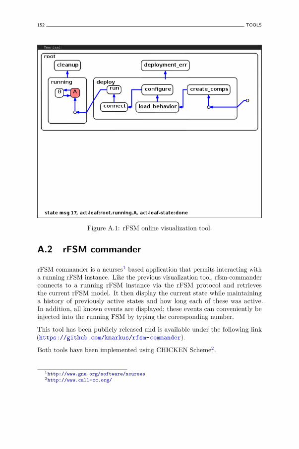
152 TOOLS
Figure A.1: rFSM online visualization tool.
A.2 rFSM commander
rFSM commander is a ncurses1 based application that permits interacting witha running rFSM instance. Like the previous visualization tool, rfsm-commanderconnects to a running rFSM instance via the rFSM protocol and retrievesthe current rFSM model. It then display the current state while maintaininga history of previously active states and how long each of these was active.In addition, all known events are displayed; these events can conveniently beinjected into the running FSM by typing the corresponding number.
This tool has been publicly released and is available under the following link(https://github.com/kmarkus/rfsm-commander).
Both tools have been implemented using CHICKEN Scheme2.
1http://www.gnu.org/software/ncurses2http://www.call-cc.org/
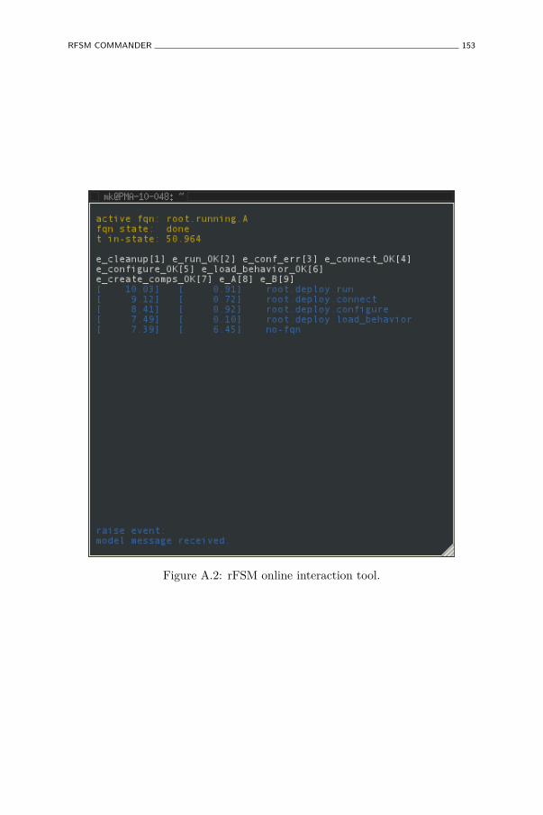
RFSM COMMANDER 153
Figure A.2: rFSM online interaction tool.

References
Abdellatif, T., S. Bensalem, J. Combaz, L. de Silva, and F. Ingrand (2012).Rigorous design of robot software: A formal component-based approach.Robotics and Autonomous Systems 60 (12), 1563 – 1578.
Agerholm, S. and P. G. Larsen (1999). A lightweight approach to formalmethods. In Proceedings of the International Workshop on Current Trendsin Applied Formal Method: Applied Formal Methods, FM-Trends 98,London, UK, UK, pp. 168–183. Springer-Verlag.
Albu-Schäffer, A., S. Haddadin, C. Ott, A. Stemmer, T. Wimböck, andG. Hirzinger (2007). The DLR lightweight robot: design and controlconcepts for robots in human environments. Industrial Robot: AnInternational Journal 34 (5), 376–385.
Alur, R. and D. L. Dill (1994). A theory of timed automata. TheoreticalComputer Science 126 (2), 183–235.
Ando, N., T. Suehiro, and T. Kotoku (2008). A software platform forcomponent based RT-system development: OpenRTM-Aist. In Conf.Simulation, Modeling, and Programming of Autonomous Robots, Venice,Italia, pp. 87–98.
Andrade, L., J. L. Fiadeiro, J. Gouveia, and G. Koutsoukos (2002).Separating computation, coordination and configuration. Journal ofsoftware maintenance and evolution: research and practice 14, 353–369.
Arbab, F. (1998). What do you mean, coordination? In Bulletin of the DutchAssociation for Theoretical Computer Science (NVTI), pp. 11–22.
Arbab, F. (2004, June). Reo: a channel-based coordination model forcomponent composition. Mathematical. Structures in Comp. Sci. 14 (3),329–366.
Arbab, F., I. Herman, and P. Spilling (1993, February). An overview ofmanifold and its implementation. Concurrency: Pract. Exper. 5 (1), 23–70.
155
156 REFERENCES
Atkinson, C. and T. Kühne (2003). Model-driven development: ametamodeling foundation. IEEE software 20 (5), 36–41.
Autosar Consortium (2003). Autosar—AUTomotive Open System ARchitec-ture. http://www.automationml.org.
Baillie, J.-C. (2004). Urbi: A universal language for robotic control.International journal of Humanoid Robotics.
Bass, L., P. Clements, and R. Kazman (2003). Software Architecture inPractice (2 ed.). Boston, MA, USA: Addison-Wesley Longman PublishingCo., Inc.
Basu, A., M. Bozga, and J. Sifakis (2006). Modeling heterogeneous real-time components in bip. In Proceedings of the Fourth IEEE InternationalConference on Software Engineering and Formal Methods, SEFM ’06,Washington, DC, USA, pp. 3–12. IEEE Computer Society.
Bauer, N. and S. Engell (2002). A comparison of sequential function chartsand statecharts and an approach towards integration. In Proceedings ofthe Workshop INT’02, Grenoble 2002, pp. 58–69.
Bensalem, S., L. de Silva, F. Ingrand, and R. Yan (2011). A verifiable andcorrect-by-construction controller for robot functional levels. Journal ofSoftware Engineering in Robotics 2 (1), 1–19.
Bentley, J. (1986, August). Programming pearls: little languages. Commun.ACM 29 (8), 711–721.
Bézivin, J. (2005). On the unification power of models. Software and SystemsModeling 4 (2), 171–188.
Biggs, G. and B. MacDonald (2003). A survey of robot programming systems.http://citeseer.ist.psu.edu/biggs03survey.html.
Billington, D., V. Estivill-Castro, R. Hexel, and A. Rock (2010). Modellingbehaviour requirements for automatic interpretation, simulation anddeployment. In N. Ando, S. Balakirsky, T. Hemker, M. Reggiani,and O. von Stryk (Eds.), Simulation, Modeling, and Programming forAutonomous Robots, Volume 6472 of Lecture Notes in Computer Science,pp. 204–216. Springer Berlin / Heidelberg.
Bjarnason, E., G. Hedin, and K. Nilsson (1999, March). Interactive languagedevelopment for embedded systems. Nordic Journal of Computing 6 (1),36–54.
Bohren, J. and S. Cousins (2010, dec.). The smach high-level executive [rosnews]. Robotics Automation Magazine, IEEE 17 (4), 18 –20.
Börger, E. and R. F. Stärk (2003). Abstract State Machines. A Method forHigh-Level System Design and Analysis. Springer.

REFERENCES 157
Borland, S. (2003). Transforming statechart models to DEVS. Master’s thesis,Montreal, Canada.
Botelho, S. and R. Alami (1999). M+: a scheme for multi-robot cooperationthrough negotiated task allocation and achievement. In Proceedings.1999 IEEE International Conference on Robotics and Automation, 1999.,Volume 2, pp. 1234 –1239 vol.2.
Breen, M. (2004). Statecharts: Some critical observations.Bruyninckx, H. and J. De Schutter (1996). Specification of force-controlled
actions in the “Task Frame Formalism”: A survey. IEEE Transactionson Robotics and Automation 12 (5), 581–589.
Bruyninckx, H., N. Hochgeschwender, L. Gherardi, M. Klotzbuecher,G. Kraetzschmar, D. Brugali, A. Shakhimardanov, J. Paulus, M. Reckhaus,H. Garcia, D. Faconti, and P. Soetens. The Brics Component Model: Amodel-based development paradigm for complex robotics software systems.
Burmester, S., H. Giese, and M. Tichy (2004). Model-driven development ofreconfigurable mechatronic systems with mechatronic uml. In U. Aßmann,M. Aksit, and A. Rensink (Eds.), MDAFA, Volume 3599 of Lecture Notesin Computer Science, pp. 47–61. Springer.
Chanel, C. P. C., F. Teichteil-Königsbuch, and C. Lesire (2012). Pomdp-basedonline target detection and recognition for autonomous uavs. In ECAI2012 - 20th European Conference on Artificial Intelligence., Volume 242of Frontiers in Artificial Intelligence and Applications, pp. 955–960.
Conway, M. E. (1963, July). Design of a separable transition-diagram compiler.Commun. ACM 6, 396–408.
Coste-Maniere, E. and N. Turro (1997). The MAESTRO language and itsenvironment: specification, validation and control of robotic missions. SeeIROS97 (1997), pp. 836–841.
Crockford, D. (2006). The application/json Media Type for JavaScript ObjectNotation (JSON). http://tools.ietf.org/html/rfc4627.
David, R. and H. Alla (1992). Petri Nets and Grafcet: Tools for ModellingDiscrete Event Systems. Upper Saddle River, NJ, USA: Prentice-Hall, Inc.
De Laet, T., S. Bellens, and H. Bruyninckx (2012). Semantics underlyinggeometric relations between rigid bodies in robotics. https://retf.info/rrfcs/0005. Last visited September 2012.
De Laet, T., S. Bellens, H. Bruyninckx, and J. De Schutter (2012). Geometricrelations between rigid bodies: from semantics to software. IEEE Roboticsand Automation Magazine.
158 REFERENCES
De Laet, T., S. Bellens, R. Smits, E. Aertbeliën, H. Bruyninckx, andJ. De Schutter (2012). Geometric relations between rigid bodies: Semanticsfor standardization. IEEE Robotics and Automation Magazine.
De Schutter, J., T. De Laet, J. Rutgeerts, W. Decré, R. Smits, E. Aertbeliën,K. Claes, and H. Bruyninckx (2007). Constraint-based task specificationand estimation for sensor-based robot systems in the presence of geometricuncertainty. The International Journal of Robotics Research 26 (5), 433–455.
De Schutter, J. and H. Van Brussel (1988). Compliant robot motion I.A formalism for specifying compliant motion tasks. The InternationalJournal of Robotics Research 7 (4), 3–17.
Delanote, D., S. Van Baelen, W. Joosen, and Y. Berbers (2008, april). UsingAADL to model a protocol stack. In Engineering of Complex ComputerSystems, 2008. ICECCS 2008. 13th IEEE International Conference on,pp. 277 –281.
DFKI (2011). Rock: the robot construction kit. http://www.rock-robotics.org. Last visited November 2012.
Dijkstra, E. W. (1982). On the role of scientific thought. In Selected Writingson Computing: A Personal Perspective, pp. 60–66. Springer-Verlag.
Dragert, C., J. Kienzle, and C. Verbrugge (2011). Toward high-level reuseof statechart-based ai in computer games. In Proceedings of the 1stInternational Workshop on Games and Software Engineering, GAS ’11,New York, NY, USA, pp. 25–28. ACM.
Dromey, R. (2003, sept.). From requirements to design: formalizing the keysteps. In First International Conference on Software Engineering andFormal Methods., pp. 2 –11.
Eclipse Foundation. The Eclipse Integrated Development Environment. http://www.eclipse.org.
Eclipse Foundation. Eclipse Modelling Framework Project. http://www.eclipse.org/modeling/emf/.
Eker, J., J. W. Janneck, E. A. Lee, J. Liu, X. Liu, J. Ludvig, S. Neuendorffer,S. Sachs, and Y. Xiong (2003). Taming heterogeneity—The Ptolemyapproach. Proceedings of the IEEE 91 (1), 127–144.
Elmqvist, H., F. Gaucher, S. Mattsson, and F. Dupont (2012). State Machinesin Modelica. In M. Otter and D. Zimmer (Eds.), Proceedings of 9thInternational Modelica Conference, Munich, Germany.
Elrad, T., O. Aldawud, and A. Bader (2002). Aspect-oriented modeling:Bridging the gap between implementation and design. In D. Batory,C. Consel, and W. Taha (Eds.), Generative Programming and Component
REFERENCES 159
Engineering, Volume 2487 of Lecture Notes in Computer Science, pp.189–201. Springer Berlin / Heidelberg.
Eshuis, R. (2009). Reconciling statechart semantics. Sci. Comput.Program. 74 (3), 65–99.
Finkemeyer, B., T. Kröger, and F. M. Wahl (2005). Executing assemblytasks specified by manipulation primitive nets. Advanced Robotics 19 (5),591–611.
Flatscher, R. G. (2002). Metamodeling in EIA/CDIF–Meta-Metamodel andMetamodels. ACM Trans. on Modeling and Computer Simulation 12 (4),322–342.
Fleury, S., M. Herrb, and R. Chatila (1997). GenoM: a tool for the specificationand the implementation of operating modules in a distributed robotarchitecture. See IROS97 (1997), pp. 842–848.
Fowler, M. (2005, Juni). Language workbenches: The killer-app for domainspecific languages?
Gamha, Y., N. Bennacer, L. Ben Romdhane, G. Vidal-Naquet, and B. Ayeb(2007, july). A statechart-based model for the semantic composition ofweb services. In 2007 IEEE Congress on Services, pp. 49–56.
Gamma, E., R. Helm, R. Johnson, and J. Vlissides (1995). Design patterns:elements of reusable object-oriented software. Reading, MA: Addison-Wesley.
Gancet, J., G. Hattenberger, R. Alami, and S. Lacroix (2005, aug.). Taskplanning and control for a multi-uav system: architecture and algorithms.In IROS2005, pp. 1017–1022.
Gansner, E. R. and S. C. North (2000). An open graph visualization systemand its applications to software engineering. SOFTWARE - PRACTICEAND EXPERIENCE 30 (11), 1203–1233.
Gat, E. (1991, apr). Alfa: a language for programming reactive robotic controlsystems. In Proceedings of the 1991 IEEE International Conference onRobotics and Automation, Volume 2, Sacramento, CA, pp. 1116–1121.ICRA91.
Gateau, T., C. Lesire, and M. Barbier (2012). Robust strategies for multirobotteam collaboration under uncertain communications. In InternationalSymposium on Distributed Autonomous Robotic Systems (DARS), Postersession, Baltimore, MD, USA.
Gelernter, D. (1985, January). Generative communication in linda. ACMTrans. Program. Lang. Syst. 7 (1), 80–112.
Gelernter, D. and N. Carriero (1992). Coordination languages and theirsignificance. Communications of the ACM 35 (2), 97–107.
160 REFERENCES
Gerum, P. (2004). Xenomai – implementing a rtos emulation framework ongnu/linux.
Ghosal, A. (2008, Jan). A Hierarchical Coordination Language for ReliableReal-Time Tasks. Ph. D. thesis, EECS Department, University ofCalifornia, Berkeley.
Gleixner, T. (2011). cyclictest. https://rt.wiki.kernel.org/index.php/Cyclictest. Last visited January 2013.
Harel, D. (1987). State charts: A visual formalism for complex systems.Science of Computer Programming 8, 231–274.
Harel, D., H. Lanchover, A. Naamad, A. Pnueli, M. Politi, R. Sherman,A. Shtull-Trauring, and M. Trakhtenbrot (1990). STATEMATE: A workingenvironment for the development of complex reactive system. IEEETransactions on Software Engineering 16, 403–414.
Harel, D. and A. Naamad (1996). The STATEMATE semantics of statecharts.ACM Trans. on Software Engineering Methodolody 5 (4), 293–333.
Henzinger, T. (1996, jul). The theory of hybrid automata. In Logic inComputer Science, 1996. LICS ’96. Proceedings., Eleventh Annual IEEESymposium on, pp. 278–292.
Hewitt, C., P. Bishop, and R. Steiger (1973). A universal modular ACTORformalism for artificial intelligence. In IJCAI1973, pp. 235–245.
Hoare, C. A. R. (1978). Communicating sequential processes. Communicationsof the ACM 21 (8), 666–677.
Hoare, C. A. R. (1985). Communicating sequential processes. Upper SaddleRiver, NJ, USA: Prentice-Hall, Inc.
Hrúz, B. and M. Zhou (2007). Modeling and Control of Discrete-EventDynamical Systems: With Petri Nets and Other Tools. AdvancedTextbooks in Control and Signal Processing. Springer.
Hudak, P., C. Antony, H. Nilsson, and J. Peterson (2003). Arrows, robots, andfunctional reactive programming. In Lecture Notes in Computer Science,Volume 2352. Springer-Verlag.
Ierusalimschy, R., W. Celes, and L. H. de Figueiredo (2012). Lua ProgrammingLanguage. http://www.lua.org. Last visited 2012.
Ierusalimschy, R., L. H. de Figueiredo, and W. Celes (2007). The evolution oflua. In Proceedings of the third ACM SIGPLAN conference on History ofprogramming languages, HOPL III, New York, NY, USA, pp. 2–1–2–26.ACM.
Ierusalimschy, R., L. H. de Figueiredo, and W. Celes (2012). Lua 5.1 ReferenceManual. http://www.lua.org/manual/5.1/manual.html. Last visited2012.
REFERENCES 161
Ierusalimschy, R., L. H. de Figueiredo, and W. C. Filho (1996). Lua—anextensible extension language. Softw. Pract. Exper. 26 (6), 635–652.
International Electrotechnical Commission (2010). IEC 61508 Ed. 2:Functional Safety. IEC.
International Electrotechnical Commission, T. C. . (2003). IEC 61131-3 Ed.2: Programmable controllers — Part 3: Programming Languages. IEC.
IROS97 (1997). Proceedings of the 1997 IEEE/RSJ International Conferenceon Intelligent Robots and Systems, Grenoble, France. IROS97.
ISO/IEC/IEEE (2010, dec). Systems and software engineering – vocabulary.Technical report.
Jackson, D. (2002, April). Alloy: a lightweight object modelling notation.ACM Trans. Softw. Eng. Methodol. 11 (2), 256–290.
Jackson, D. and J. Wing (1996, April). Lightweight formal methods. IEEEComputer , 21–22.
Jensen, K. (1987). Coloured petri nets. In W. Brauer, W. Reisig, andG. Rozenberg (Eds.), Petri Nets: Central Models and Their Properties,Volume 254 of Lecture Notes in Computer Science, pp. 248–299. SpringerBerlin / Heidelberg. 10.1007/BFb0046842.
Joyeux, S., R. Philippsen, R. Alami, and S. Lacroix (2009). A plan managerfor multi-robot systems. The International Journal of Robotics Research.
Kaelbling, L. P. (1987). Rex: A symbolic language for the design andparallel implementation of embedded systems. In Proceedings of the AIAAConference on Computers in Aerospace, Wakefield, Massachusetts.
Kaelbling, L. P. (1988). Goals as parallel program specifications. In Proceedingsof the Seventh National Conference on Artificial Intelligence, Minneapolis-St. Paul, Minnesota.
Kalibera, T., F. Pizlo, A. L. Hosking, and J. Vitek (2011). Scheduling real-timegarbage collection on uniprocessors. ACM Trans. Comput. Syst. 29 (3), 8.
Kiczales, G. (1996). Aspect-oriented programming. ACM Computing Surveys,154.
Klotzbuecher, M. (2011). rFSM statecharts. http://www.orocos.org/rFSM.Last visited January 2012.
Klotzbuecher, M. (2012). uMF micro-modelling framework. https://github.com/kmarkus/umf. Last visited September 2012.
Klotzbuecher, M., G. Biggs, and H. Bruyninckx (2012, November). Purecoordination using the coordinator–configurator pattern. In Proceedingsof the 3rd International Workshop on Domain-Specific Languages andmodels for ROBotic systems.

162 REFERENCES
Klotzbuecher, M. and H. Bruyninckx (2011, October). Hard real-time controland coordination of robot tasks using Lua. In Proceedings of the ThirteenthReal-Time Linux Workshop.
Klotzbuecher, M. and H. Bruyninckx (2012, September). A lightweight,composable metamodelling language for specification and validation ofinternal domain specific languages. In Proceedings of the 8th InternationalWorkshop on Model-based Methodologies for Pervasive and EmbeddedSoftware.
Klotzbuecher, M., R. Smits, H. Bruyninckx, and J. De Schutter (2011).Reusable hybrid force-velocity controlled motion specifications withexecutable domain specific languages. In Proceedings of the 2011IEEE/RSJ International Conference on Intelligent Robots and Systems,San Francisco, California, pp. 4684–4689. IROS2011.
Klotzbuecher, M., P. Soetens, and H. Bruyninckx (2010). OROCOS RTT-Lua: an Execution Environment for building Real-time Robotic DomainSpecific Languages. In International Workshop on Dynamic languages forRObotic and Sensors, pp. 284–289.
Kopetz, H. (1993). Should responsive systems be event-triggered or time-triggered ? Institute of Electronics, Information, and CommunicationsEngineers Transactions on Information and Systems E76-D(11), 1325–1332.
Kopetz, H. and G. Bauer (2003, jan). The time-triggered architecture.Proceedings of the IEEE 91 (1), 112–126.
Korean Institute for Advanced Intelligent Systems. OPRoS. http://opros.or.kr/. Last visited November 2010.
Kortenkamp, D. and R. G. Simmons (2008). Robotic systems architecturesand programming. In B. Siciliano and O. Khatib (Eds.), Springer Handbookof Robotics, pp. 187–206. Springer.
Lesser, V., K. Decker, T. Wagner, N. Carver, A. Garvey, B. Horling,D. Neiman, R. Podorozhny, M. N. Prasad, A. Raja, R. Vincent, P. Xuan,and X. Q. Zhang (2004, July). Evolution of the gpgp/taems domain-independent coordination framework. Autonomous Agents and Multi-Agent Systems 9 (1-2), 87–143.
Mallet, F. and R. Simone (2009). MARTE vs. AADL for Discrete-Event andDiscrete-Time Domains. In M. Radetzki (Ed.), Languages for EmbeddedSystems and their Applications, Volume 36 of Lecture Notes in ElectricalEngineering, pp. 27–41. Springer Netherlands.
Marty, J. C., A. E. K. Sahraoui, and M. Sartor (1998, November). Statechartsto specify the control of automated manufacturing systems. InternationalJournal of Production Research 36 (11), 3183–3215.

REFERENCES 163
Masmano, M., I. Ripoll, P. Balbastre, and A. Crespo (2008). A constant-timedynamic storage allocator for real-time systems. Real-Time Syst. 40 (2),149–179.
Mason, M. T. (1979). Compliance and force control for computer controlledmanipulators. Master’s thesis, Department of Electrical Engineering andComputer Science, Massachusetts Institute of Technology, Cambridge,MA.
Mason, M. T. (1981). Compliance and force control for computercontrolled manipulators. IEEE Transactions on Systems, Man, andCybernetics SMC-11 (6), 418–432.
MathWorks. Design and simulate state charts by The Mathworks. www.mathworks.de/products/stateflow/.
McCarragher, B. J. (1994). Petri net modeling for robotic assembly andtrajectory planning. IEEE Transactions on Industrial Electronics 41 (6),631–640.
Medeiros, A. A. D. (1998, 04). A survey of control architectures forautonomous mobile robots. Journal of the Brazilian Computer Society 4.
Mellor, S. J. and M. Balcer (2002). Executable UML: A Foundation forModel-Driven Architectures. Boston, MA, USA: Addison-Wesley LongmanPublishing Co., Inc. Foreword By-Jacoboson, Ivar.
Mens, T. and P. Van Gorp (2006). A taxonomy of model transformation.Electronic Notes in Theoretical Computer Science 152 (0), 125 – 142.
Merkle, B. (2010). Textual modeling tools: overview and comparisonof language workbenches. In Proceedings of the ACM internationalconference companion on Object oriented programming systems languagesand applications companion, SPLASH ’10, New York, NY, USA, pp.139–148. ACM.
Mernik, M., J. Heering, and A. M. Sloane (2005, December). When andhow to develop domain-specific languages. ACM Comput. Surv. 37 (4),316–344.
Merz, T., P. Rudol, and M. Wzorek (2006, july). Control system frameworkfor autonomous robots based on extended state machines. In InternationalConference on Autonomic and Autonomous Systems, 2006. ICAS ’06.2006, pp. 14.
Mikk, E., Y. Lakhnech, M. Siegel, and G. J. Holzmann (1998). Implementingstatecharts in promela/spin. In Proceedings of the Second IEEE Workshopon Industrial Strength Formal Specification Techniques, WIFT ’98,Washington, DC, USA, pp. 90–. IEEE Computer Society.
164 REFERENCES
Miller, J. and J. Mukerji (2003). MDA Guide version 1.0.1. Technical report,Object Management Group (OMG).
Modelica Association. Modelica: Language design for multi-domain modeling.http://www.modelica.org/.
Object Management Group. Object Constraint Language. http://www.omg.org/spec/OCL/.
Object Management Group. OMG. http://www.omg.org.Object Management Group. Query View Transformation. http://www.omg.
org/spec/QVT/.Object Management Group. Semantics of a Foundational Subset for
Executable UML Models (fUML), version 1.0. http://www.omg.org/spec/FUML/1.0/.
Object Management Group (2006). Meta Object Facility (MOF) core spec-ification. http://www.omg.org/technology/documents/formal/data_distribution.htm.
Object Management Group (2009). UML specification. http://www.omg.org/spec/UML.
Object Management Group (2011). Unified Modeling Language (UML)superstructure specification, version 2.4.1. http://www.uml.org/.
Object Management Group (2012). Systems Modelling Language (SysML),version 1.3. http://www.sysml.org/.
Ogasawara, T. (1995). An algorithm with constant execution timefor dynamic storage allocation. In RTCSA ’95: Proceedings of the2nd International Workshop on Real-Time Computing Systems andApplications, Washington, DC, USA, pp. 21. IEEE Computer Society.
Olofson, D. (2005). The Extensible Embeddable Language. http://eel.olofson.net/. Last visited January 2013.
Otter, M., M. Malmheden, H. Elmqvist, S. E. Mattson, and C. Johnsson(2009). A new formalism for modeling of reactive and hybrid systems. InModelica Conference, pp. 364–377.
Pall, M. (2011). Luajit: The lua just-in-timer compiler. http://luajit.org.Last visited January 2013.
Papadopoulos, G. A. and F. Arbab (1998). Coordination models andlanguages. Technical report, Amsterdam, The Netherlands, TheNetherlands.
Perlis, A. J. (1982, September). Special feature: Epigrams on programming.SIGPLAN Not. 17 (9), 7–13.
REFERENCES 165
Petersson, J., P. Hudak, and C. Elliott (1999). Lambda in motion: Controllingrobots with haskell. In Lecture Notes in Computer Science, Volume 1551,pp. 91–105. Springer-Verlag.
Petri, C. A. (1962). Kommunikation mit Automaten. Ph. D. thesis, Institutfür instrumentelle Mathematik, Bonn.
Pizlo, F. and J. Vitek (2008). Memory management for real-time java: Stateof the art. 2008 11th IEEE International Symposium on Object andComponent-Oriented Real-Time Distributed Computing (ISORC) 0, 248–254.
Pohlmann, U., S. Dziwok, J. Suck, B. Wolf, C. C. Loh, and M. Tichy (2012).A modelica library for real-time coordination modeling. In M. Otter andD. Zimmer (Eds.), Proceedings of 9th International Modelica Conference,Munich, Germany.
Prassler, E., H. Bruyninckx, K. Nilsson, and A. Shakhimardanov (2009).The use of reuse for designing and manufacturing robots. Technicalreport, Robot Standards project. http://www.robot-standards.eu//Documents_RoSta_wiki/whitepaper_reuse.pdf.
Quigley, M., K. Conley, B. Gerkey, J. Faust, T. B. Foote, J. Leibs, R. Wheeler,and A. Y. Ng (2009). ROS: an open-source Robot Operating System. InICRA Workshop on Open Source Software.
Radestock, M. and S. Eisenbach (1996). Coordination in evolving systems.In Trends in Distributed Systems. CORBA and Beyond, pp. 162–176.Springer-Verlag.
Ramadge, P. J. and W. M. Wonham (1987, January). Supervisory control of aclass of discrete event processes. SIAM J. Control Optim. 25 (1), 206–230.
Real-Time for Java Expert Group (RTJEG) (2005, June). Real-timespecification for java (rtsj). http://www.rtsj.org/specjavadoc/book_index.html.
Renggli, L., S. Ducasse, T. Gîrba, and O. Nierstrasz (2010). Domain-specificprogram checking. In J. Vitek (Ed.), Objects, Models, Components,Patterns, Volume 6141 of Lecture Notes in Computer Science, pp. 213–232.Springer Berlin / Heidelberg.
Renggli, L., S. Ducasse, and A. Kuhn (2007). Magritte - a meta-drivenapproach to empower developers and end users. In G. Engels, B. Opdyke,D. Schmidt, and F. Weil (Eds.), Model Driven Engineering Languagesand Systems, Volume 4735 of Lecture Notes in Computer Science, pp.106–120. Springer Berlin / Heidelberg.
RoboHow. The robohow project. http://robohow.eu/.

166 REFERENCES
Rosell, J. (2004). Assembly and task planning using Petri nets: A survey.Proceedings of the Institution of Mechanical Engineers, Part B: Journalof Engineering Manufacture 218, 987–994.
ROSETTA. Robot control for skilled execution of tasks in natural interactionwith humans; based on autonomy, cumulative knowledge and learning.http://www.fp7rosetta.eu/.
SAE International. AADL: The SAE Architecture Analysis and DesignLanguage. http://www.aadl.info.
Schreiber, G., A. Stemmer, and R. Bischoff (2010, May). The FastResearch Interface for the KUKA Lightweight Robot. In IEEE Workshopon Innovative Robot Control Architectures for Demanding (Research)Applications – How to Modify and Enhance Commercial Controllers(ICRA 2010).
Shakhimardanov, A., N. Hochgeschwender, M. Reckhaus, and G. K.Kraetzschmar (2011). Analysis of software connectors in robotics. InProceedings of the IEEE International Conference on Robotics andAutomation, Shangai, China, pp. 1030–1035.
Sheridan, T. B. (1992). Telerobotics, Automation, and Human SupervisoryControl. Cambridge, MA, USA: MIT Press.
Shlaer, S. and S. J. Mellor (1988). Object-oriented systems analysis: modelingthe world in data. Upper Saddle River, NJ, USA: Yourdon Press.
Simmons, R. and D. Apfelbaum (1998, oct). A task description language forrobot control. In Intelligent Robots and Systems, 1998. Proceedings., 1998IEEE/RSJ International Conference on, Volume 3, pp. 1931 –1937 vol.3.
Simons, A. J. H. (2000). On the compositional properties of UML statechartdiagrams. In Rigorous Object-Oriented Methods, Workshops in Computing.BCS.
Smits, R. (2010, May). Robot skills: design of a constraint-based methodologyand software support. Ph. D. thesis, Department of MechanicalEngineering, Katholieke Universiteit Leuven, Belgium.
Smits, R., H. Bruyninckx, and E. Aertbeliën (2001). KDL: Kinematics andDynamics Library. http://www.orocos.org/kdl. Last visited August2012.
Smits, R., T. De Laet, K. Claes, H. Bruyninckx, and J. De Schutter (2008).iTaSC: a tool for multi-sensor integration in robot manipulation. InIEEE International Conference on Multisensor Fusion and Integrationfor Intelligent Systems, Seoul, South-Korea, pp. 426–433. MFI2008.
Soetens, P. (2006, May). A Software Framework for Real-Time and DistributedRobot and Machine Control. Ph. D. thesis, Department of Mechanical
REFERENCES 167
Engineering, Katholieke Universiteit Leuven, Belgium. http://www.mech.kuleuven.be/dept/resources/docs/soetens.pdf.
Soetens, P. and H. Bruyninckx (2005). Realtime hybrid task-based control forrobots and machine tools. In Proceedings of the 2005 IEEE InternationalConference on Robotics and Automation, Barcelona, Spain, pp. 260–265.ICRA2005.
Spinellis, D. (2001, feb). Notable design patterns for domain specific languages.Journal of Systems and Software 56 (1), 91–99.
Sullivan, J. (2005, june). Impediments to and incentives for automation in theair force. In Proceedings. 2005 International Symposium on Technologyand Society, 2005. Weapons and Wires: Prevention and Safety in a Timeof Fear. ISTAS 2005., pp. 102–110.
Sun Microsystems (2006). Memory management in the java hotspottm vir-tual machine. http://java.sun.com/j2se/reference/whitepapers/memorymanagement_whitepaper.pdf.
Tarr, P., H. Ossher, W. Harrison, and S. M. Sutton, Jr. (1999). N degrees ofseparation: multi-dimensional separation of concerns. In Proceedings ofthe 21st international conference on Software engineering, ICSE ’99, NewYork, NY, USA, pp. 107–119. ACM.
Van de Poel, P., W. Witvrouw, H. Bruyninckx, and J. De Schutter (1993).An environment for developing and optimizing compliant robot motiontasks. In Proceedings of the 1993 International Conference on AdvancedRobotics, Tokyo, Japan, pp. 713–718.
van Deursen, A., P. Klint, and J. Visser (2000, June). Domain-specificlanguages: an annotated bibliography. SIGPLAN Not. 35 (6), 26–36.
Vanthienen, D., T. De Laet, R. Smits, and H. Bruyninckx (2011). itascsoftware. http://www.orocos.org/itasc. Last visited March 2013.
von der Beeck, M. (1994). A comparison of statecharts variants. InH. Langmaack, W.-P. de Roever, and J. Vytopil (Eds.), Formal Techniquesin Real-Time and Fault-Tolerant Systems, Volume 863 of Lecture Notesin Computer Science, pp. 128–148. Springer Berlin / Heidelberg.
W3C (2001). XSD: XML Schema Definition. http://www.w3.org/XML/Schema.
W3C (2010). State Chart XML (SCXML): State machine notation for controlabstraction. W3C Working Draft. http://www.w3.org/TR/scxml/.
Wainer, G. A. and P. Mosterman (2011). Discrete-Event Modeling andSimulation: Theory and Applications. Taylor and Francis.
Willow Garage (2008). Robot Operating System (ROS). http://www.ros.org. Last visited 2012.
168 REFERENCES
Wittocx, J., M. Mariën, and M. Denecker (2008, Nov). The IDP system: Amodel expansion system for an extension of classical logic. In M. Denecker(Ed.), Proceedings of the 2nd Workshop on Logic and Search, pp. 153–165.ACCO.
Witvrouw, W., P. Van de Poel, and J. De Schutter (1995). Comrade:Compliant motion research and development environment. In 3rdIFAC/IFIP workshop on Algorithms and Architectures for Real-TimeControl, Ostend, Belgium, pp. 81–87.
Zeigler, B. P. (1976). Theory of Modeling and Simulation. John Wiley.Zhao, Q. and B. Krogh (2006, sept.). Formal verification of statecharts
using finite-state model checkers. Control Systems Technology, IEEETransactions on 14 (5), 943 –950.
Curriculum
Personal data
Markus Klotzbücherborn September 7, 1978 in Stanford, [email protected] [email protected]
Education
• 2009-2013: PhD student at the Department of Mechanical Engineering,University of Leuven, Belgium.
– Supervised by Prof. Herman Bruyninckx.
• 2008-2009 Predoctoral phase, attending courses and project work atUniversity of Leuven.
• 1999-2004: Computer Engineering at the University of Applied SciencesKonstanz, Germany.
– Semester abroad in 2002: Pontifical Catholic University of Paraná(Pontifícia Universidade Católica do Paraná), Brazil.
– Thesis: Development of a Linux Overlay Filesystem for SoftwareUpdates in Embedded Systems.
169
170 CURRICULUM
Experience
• 2004-2009: Freelance consultant
– Software development for embedded and real-time systems in theautomation and telecommunication industry.
– Teaching industrial seminars on Embedded Linux System Designand Linux Device Driver Development (both in cooperation withDENX Software Engineering).
• 2002: Internship at Siemens–CITS (Centro Internacional de Tecnologiade Software) in Curitiba, Brazil.
– Participation in software development of a high end telecommunica-tion product.
• 2000-2001: Internship at UPAQ Ltd., Zurich, Switzerland.
– Work in network security and system administration for one semester.
• 1998-1999: Civilian service as paramedic at the German Red Cross.
– Training as Rettungssanitäter (second highest paramedical qualifica-tion).
– Afterwards further voluntary work and training.
Publications
Articles in Internationally Reviewed Journals
1. Klotzbücher, M., Bruyninckx, H. (2012). Coordinating Robotic Tasks andSystems with rFSM Statecharts. JOSER: Journal of Software Engineeringfor Robotics, 3 (1), 28-56.
Papers at international scientific conferences andsymposia, published in full in proceedings
1. Bruyninckx, H., Hochgeschwender, N., Gherardi, L., Klotzbücher, M.,Kraetzschmar, G., Brugali, D., Shakhimardanov, A., Paulus, J., Reckhaus,M., Garcia, H., Faconti, D. and Soetens, P. (2013). The BRICS ComponentModel: A Model-Based Development Paradigm For Complex RoboticsSoftware Systems.
2. Klotzbücher, M., Bruyninckx, H. (2012). A Lightweight, ComposableMetamodelling Language for Specification and Validation of InternalDomain Specific Languages. Proceedings of the 8th InternationalWorkshop on Model-based Methodologies for Pervasive and EmbeddedSoftware (MOMPES ’12), ASM, Essen, 3-7 September 2012, LNCS.
3. Brugali, D., Gherardi, L., Klotzbücher, M., Bruyninckx, H. (2012). ServiceComponent Architectures in Robotics: The SCA-Orocos Integration. InHähnle, R. (Ed.), Knoop, J. (Ed.), Margaria, T. (Ed.), Schreinerh, D.(Ed.), Steffen, B. (Ed.), International Workshops, SARS 2011 and MLSC2011, Held Under the Auspices of ISoLA 2011 in Vienna, Austria, October17-18, 2011: Vol. 336. ISoLA. Vienna, October 17-18, 2011 (pp. 46-60).Berlin Heidelberg: Springer.
171
172 PUBLICATIONS
4. Klotzbücher, M., Smits, R., Bruyninckx, H., De Schutter, J. (2011).Reusable Hybrid Force-Velocity controlled Motion Specifications withexecutable Domain Specific Languages. IEEE/RSJ InternationalConference on Intelligent Robots and Systems. San Francisco, USA.,25-30 September, 2011 IEEE.
5. Klotzbücher, M., Bruyninckx, H. (2011). Hard Real-Time Control andCoordination of Robot Tasks using Lua. Proceedings of the ThirteenthReal-Time Linux Workshop. Real Time Linux Workshop. Czech TechnicalUniversity, Prague, 20-22 October 2011 (pp. 37-43) Open SourceAutomation Development Lab (OSADL) eG.
6. Klotzbücher, M., Soetens, P., Bruyninckx, H. (2010). OROCOS RTT-Lua: an Execution Environment for building Real-time Robotic DomainSpecific Languages. Proceedings of SIMPAR 2010 Workshops. SIMPARWorkshops, Darmstadt, Germany, 15-16 November 2010 (pp. 284-289).
Meeting abstracts, presented at international sci-entific conferences and symposia, published or notpublished in proceedings or journals
1. Buys, K., Bellens, S., Vanthienen, N., De Laet, T., Smits, R., Klotzbücher,M., Decré, W., Bruyninckx, H., De Schutter, J. (2011). Haptic couplingwith augmented feedback between the KUKA youBot and the PR2 robotarms. International Conference on Intelligent Robots and Systems. SanFrancisco, Califormia, 25-30 September, 2011.
2. Vanthienen, N., De Laet, T., Smits, R., Buys, K., Bellens, S., Klotzbücher,M., Bruyninckx, H., De Schutter, J. (2011). Demonstration of iTaSC asa unified framework for task specification, control, and coordination formobile manipulation. IEEE/RSJ International Conference on IntelligentRobots and Systems. San Francisco, 25-30 September 2011.
3. Buys, K., Bellens, S., Vanthienen, N., Decré, W., Klotzbücher, M., DeLaet, T., Smits, R., Bruyninckx, H., De Schutter, J. (2011). Hapticcoupling with the PR2 as a demo of the OROCOS - ROS - Blenderintegration. IROS. San Francisco, California, 25-30 September 2011.
4. Vanthienen, N., De Laet, T., Decré, W., Smits, R., Klotzbücher, M.,Buys, K., Bellens, S., Gherardi, L., Bruyninckx, H., De Schutter, J.(2011). iTaSC as a unified framework for task specification, control,and coordination, demonstrated on the PR2. IEEE/RSJ International
PUBLICATIONS 173
Conference on Intelligent Robots and Systems. San Francisco, 25-30September 2011.
5. Soetens, P., Klotzbücher, M. (2009) Real Time Toolkit for Open RobotControl Software. Xenomai User Meeting (XUM), September 28, 2009.Eleventh Real Time Linux Workshop, TU Dresden, Germany.


FACULTY OF ENGINEERINGDEPARTMENT OF MECHANICAL ENGINEERING
PRODUCTION ENGINEERING, MACHINE DESIGN AND AUTOMATION DIVISIONCelestijnenlaan 300B box 2420
B-3001 [email protected]
http://www.mech.kuleuven.be