Embed Size (px)
Citation preview


rexresearch.com Home
Stanislav ADAMENKO
Proton-21 Fusion
Proton 21 Chernovola Street, 48a Vishnevoe, Kievo-Svyatoshiskyi 08132 Ukraine
Phone/Fax +38044-5991046 --- Phone: +38044-5990826 --- Mob.phone: +38063-4256260 E-mail: [email protected] Spoken languages: English, Russian and Ukrainian.
Downloadable Publications: http://www.proton21.com.ua/articles_en.html
Proton-21 Introduction Tim Ventura : Proton 21 - The New Fusion
Perpetual Power GeneratorStep by step plans to make magnetic energy to slashyour power billwww.motormagnet.com/MM6/index.html
Green Energy SolutionsBuild Perpetual Motion Machine Find Out More Now!NettChoice.com/Energy-Generator
2/8/2010 Staislav Adamenko--- Proton-21 Fusio…
I:/Data_PC_CHR/…/adamenko.htm 1/33
S. Adamenko: US Patent Application # 20050200256 : Method and Device forCompressing a Substance by Impact and Plasma Cathode Thereto S. Adamenko, et al.: Technical Physics Letters 27(8): 671-673 (August 2001) --- VacuumElectric Discharge Initiated by Accelerated Nanoparticles
http://www.proton.21.com.ua
Proton-21Welcome to Electrodynamics Laboratory "Proton-21" --- the pioneer in a new field of nuclearphysics and of the new method and installation for laboratory nucleosynthesis. Laboratory
Advancements over the span of the last fifty years in many fields of scientific and technologicalresearch such as Genetics, Physics, Telecommunications and other fields has outperformedprogress in the field of Power Generation and Decontamination of Radioactive wastes. Progress inthe fields of controlled thermonuclear synthesis and radioactive wastes decontamination technologyalso lag in comparison despite investments in research by the developed nations exceeding USD100 billion.
One key issue that remains unresolved to this date in this particular field of research is thedevelopment of processes and technology for controlled ignition of self-sustaining nuclear reactions.For this, an adequate "initiator" of such controlled nuclear transformations is required; one whichwill result in a sustainable and controlled energy output and the transmutation of radioactive atomsinto stable ones.
ElectroDynamics Lab (EDL) was founded in Kiev, Ukraine in 1999 by a group of Ukrainianengineers and scientists to address the specific problem of the adequate initiator. EDL's primarymission statement was to develop a novel, safe and effective technology for radioactive wastesdecontamination. Today, privately funded EDL has evolved into a leading edge Research andDevelopment center employing in excess of 120 researchers and scientists. The proven results of itsresearch and its proprietary process, currently being patented, are able today to address theunresolved issue of nuclear wastes transformation.
EDL's results are revolutionary in their nature and are leading to important commercial and industrialbreakthrough applications.
Primary Focus of EDL's Research:
The primary focus of EDL's research is based on a newly developed and self sustainable processwhich leads, through a controlled stimulation, to the collapse of condensed matter. In this collapsedstate thus created, the effect of the Coulomb barrier becomes insignificant, and a rapidtransmutation of elements and isotopes occurs and can be observed.
Main Research Results:
The first successful experiment was performed on February 24, 2000 in a specially created andproprietary set up. In fact, the 5,000+ successful experiments in controlled nuclei-synthesisperformed since 1999, using various targets made of light, medium, or heavy elements; haveallowed the research team at EDL to comprehend and evaluate this unique scientific breakthrough. The discovered process has been noted for its practical, environmentally friendly and extraordinary
2/8/2010 Staislav Adamenko--- Proton-21 Fusio…
I:/Data_PC_CHR/…/adamenko.htm 2/33
energy efficient attributes.
Two major outcomes have emerged from this process:
First, the creation of an energy output far exceeding the initial impact.
Second, the creation of an array of unique nuclei-synthesis elements. These new elements weretested by leading scientific laboratories in Ukraine, Russia, USA, etc, and their artificial origin wasconfirmed.
The obtained results confirm the following:
The technological process created and validated by EDL is a unique and a pioneer experimentaltechnology. It achieves record-breaking conditions for multiparticle nuclear fusion-fission reactionsin condensed matter.
The laboratory installation developed by EDL has achieved high reproducibility results in reachingappropriate conditions in a compressed format necessary for the ignition of the collectivemultiparticle fusion-fission reactions.
The new elements resulting from the nuclceosynthesis created by the EDL process are free of ?-, ?-, ?-, -active isotopes. The radiation intensity of the products never exceeds the backgroundintensity.
Elements marked with radioactive isotopes had their activity reduced due to full nuclear rebirth of aportion of the target element after the high energy impact.
The presence of long living isotopes in super heavy elements, on the border and beyond thePeriodic Table, was revealed by the nuclear transmutation. These were synthesized in quantitiesmany times exceeding those principally gained by classic methods at much reduced energy costs.
Objectives:
EDL's immediate objective is to finalize the pilot project of a new industrial prototype hundred timesexceeding the performance of the existing laboratory setup.
EDL intends to continue and expand its research work in new fields of nuclear physics: including a)laboratory astrophysics, b) physics of collective synergetic interactions of previously unknownmechanisms, and c) energy creation and transformation processes.
EDL intends to develop a series of unique, radiation safe, and environmentally appropriate,industrial technologies to be used in commercial applications.
http://www.americanantigravity.com/articles/587/1/Proton-21---The-New-Fusion/Page1.html
Proton 21 - The New Fusion
by Tim Ventura
( 09/12/2006 )
2/8/2010 Staislav Adamenko--- Proton-21 Fusio…
I:/Data_PC_CHR/…/adamenko.htm 3/33
Stanislav Adamenko on Emerging Fusion Research
By subjecting a copper electrode to a gigawatt pulse of energy, Dr. Stanislav Adamenko believesthat he's found a new form of fusion that occurs inside a millimeter sized plasma that forms in theelectrode. Has Adamenko finally cracked the code for solid-state fusion, and what potential forfuture energy does it hold? He joins us for the inside story on Proton 21's research in creating "TheNew Fusion"...
"Simply put, we're dealing with physical processes that exhibit a strongly nonlinear dependence. Agood example to consider is the amount of the excess energy released in a LENR reaction versusthe amount of the active substance involved in the experiment-- this is something that we'veexamined extensively in our own experimental research.
This nonlinear dependence explains why the majority of well-known LENR experimentsdemonstrate such extremely small yields in terms of energy production & nucleosynthesis, as well aswhy the results are so difficult to replicate or even accurately identify when they occur.
I'm sure that in the next five to ten years, collective & coherent nuclear reactions will become thefocus of major investment in the field of nuclear-energy research, and it will lead to the beginning ofa large-scale transition to a new, environmentally-friendly means of producing energy based oncollective natural nuclear transformations." - Dr. Stanislav Adamenko
http://www.americanantigravity.com/documents/Proton-21-Interview.pdf
United States Patent Application 20050200256
Adamenko, Stanislav Vasilyevich
( September 15, 2005 )
Method and Device for Compressing a Substance by Impact and PlasmaCathode Thereto
Abstract --- A method of compressing a substance by impact in axisymmetric relativistic vacuumdiodes (RVD) having a plasma cathode and an anode-enhancer including: producing anaxisymmetric target of a condensed substance, which functions at least as a part of the anode-enhancer; axially placing said electrodes; and pulse discharge of a power source via the RVD. Tocompress a substantial portion of the target substance to a superdense state, a plasma cathode isused in the form of a current-conducting rod comprising a dielectric end element having theperimeter of the rear end embracing the perimeter of the rod in the plane perpendicular to the axisof symmetry with a continuous gap, and the area of the emitting surface being greater than themaximum cross-section area of the anode-enhancer; the anode-enhancer is placed towards theplasma cathode so that the center of curvature of the working surface of the anode enhancer islocated inside the focal space of the collectively self focussing electron beam; and the anode-enhancer is acted upon by an electron beam with an electron energy not smaller than 0.2 MeV,current density not smaller than 106 A/cm2 and duration not greater than 100 ns.
Correspondence Name and Address: Abelman Frayne & Schwab : 150 East 42nd Street , New York NY 10017 US
U.S. Current Class: 313/238; U.S. Class at Publication: 313/238 ; Intern'l Class: H01J 001/00
2/8/2010 Staislav Adamenko--- Proton-21 Fusio…
I:/Data_PC_CHR/…/adamenko.htm 4/33
Description
FIELD OF INVENTION
[0001] This invention relates:
[0002] to a method for impact compression of a condensed (liquid or, preferably, solid) substanceto a superdense state in which pycnonuclear processes and inertial confinement fusion (ICFhereafter) may proceed, and
[0003] to a structure of devices based on relativistic vacuum diodes (RVD hereafter) includingplasma cathodes, designed for carrying out the said method.
[0004] This technology is intended practically for transmutation of atomic nuclei of certain chemicalelements into nuclei of other chemical elements with the purpose of:
[0005] Experimentally obtaining preferably stable isotopes of chemical elements including synthesisof stable transuranides;
[0006] Reprocessing radioactive waste containing long-lived isotopes into materials containingshort-lived isotopes and/or stable isotopes, which is particularly important in decontamination ofused gamma-ray sources, e.g., based on radioactive isotopes of cobalt widely used in industry andmedicine.
[0007] In future, this method may be useful for obtaining energy by the ICF with utilization ofpreferably solid targets.
[0008] For the purpose of this description, the following terms as employed herein and in theappended claims refer to the following concepts:
[0009] "target" is a once used for impact compression dose of at least one arbitrary isotope of atleast one chemical element, being a raw material for obtaining products of nuclear transformationsand, optionally, a primary energy carrier for energy producing;
[0010] "impact compression" is an isoentropic impact action of a self-focusing converging densitywave on at least a part of a target;
[0011] "superdense state" is such a state of at least a part of the target after it has been compressedby impact, at which state a substantial portion of the target substance transforms into electron-nuclear and electron-nucleonic plasma;
[0012] "pycnonuclear process" is such a recombinational interaction (`cold` in particular) betweencomponents of electron-nuclear and electron-nucleonic plasma of the target substance compressedto a superdense state causing at least the target isotopic composition change;
[0013] "plasma cathode" is such a consumable axisymmetric part of the RVD negative electrodewhich is able (in the beginning of the discharge pulse) to generate plasma shell (of the material of thenear-surface layer) with the near zero electron work function;
[0014] "anode-enhancer" is such once used replaceable axisymmetric part of the RVD anodewhich may be completely produced of preferably conductive (in the main) material and used as atarget itself in the simplest demonstration experiments, or has the shape of at least a single-layershell of a hard strong material inside of which a selected target is fixed also axisymmetricallyproviding the acoustic contact, when such anode-enchancer is used for industrial needs;
2/8/2010 Staislav Adamenko--- Proton-21 Fusio…
I:/Data_PC_CHR/…/adamenko.htm 5/33
[0015] "focal space" is such a volume in the RVD vacuum chamber which spatially confines acertain length of the common geometric symmetry axis of the RVD electrodes and in which (in theabsence of obstacles and under pre-set values of the area of the emitting surface of the plasmacathode, energy of electrons and current density) a pinch of electron beam is possible due tocollective self-focussing of relativistic electrons.
BACKGROUND ART
[0016] It is well known theoretically (see, e.g., U.S. Pat. No. 4,401,618) that in order to carry outa controlled nuclear fusion, it is necessary and sufficient:
[0017] First, to make a target of a microscopic size, the mass of which is usually of severalmicrograms to several milligrams,
[0018] Second, to fix the formed target in a space,
[0019] Third, to transfer a target substance into a superdense state by as uniform as possibleimpact compression of the target,
[0020] Fourth, to hold the substance of the target in such state the time enough for transmutationand/or nuclear fusion of atoms, which can be accompanied by energy release or absorption.
[0021] Worth to be mentioned that said limitations of the target mass are important mainly for theICF because 1 mg of deuterium or a mixture of deuterium and tritium has an energy equivalent ofabout 20-30 kg of trinitrotoluene.
[0022] Also theoretically obvious is the fact that transmutation and/or nuclear fusion occur actuallysimultaneously with the attainment of a superdense state. Therefore, the efforts of researchers in thefield of nuclear physics have been directed to the creation of most efficient methods and means forimpact compression of substances so far.
[0023] And, finally, it is also theoretically clear that:
[0024] such a compression is possible only under the conditions of generating a high-powermechanical impulse of the duration order of several tens of nanoseconds and focussing this impulseonto a substantial area (up to the whole) of the surface of a target located in a securely isolatedfrom the environment volume,
[0025] means for space-time compression of an energy flux are required for that purpose, such asprimary energy source, at least one energy storage, at least one converter for transforming theaccumulated energy into a mechanical impact impulse, and a mechanical striker for essentiallyisoentropic transfer of this impulse onto the target,
[0026] the problem of a sufficient set of such means and interactions between them can be solved indifferent ways depending on the purposes of the experiments with the impact compression of asubstance provided that (when connected to an industrial power network) the first but not the onlyenergy storage is usually a device based on a LC-circuit (see, e.g., collected articles: EnergyStorage, Compression and Switching, edited by W. H. Bostick, V. Nardy and O. S. F. Zucker.Plenum Press, New York and London).
[0027] For years, efforts to realize said theoretical assumptions in practice had been directed onlyto the ICF the industrial mastering of which seemed to be sufficient for the humanity to move to"energy paradise".
2/8/2010 Staislav Adamenko--- Proton-21 Fusio…
I:/Data_PC_CHR/…/adamenko.htm 6/33
[0028] For this reason, only gaseous deuterium or deuterium and tritium were used as an activesubstance from the very beginning, and targets were produced in the shape of tight empty spheresfilled with microscopic (about 0,1 mg) portions of said hydrogen isotopes. Then, the beams of laserdrivers were pointed at each such target uniformly and synchronously from many sides.
[0029] Heating of the shell caused an ablation (partial evaporation) of its outer portion. Theexpansion of the evaporated material was giving rise to reactive forces which caused implosion, i.e.uniform compression of the inner portion of the shell and active substance of the target in thedirection to the sphere center (see, e.g., (1) U.S. Pat. No. 4,401,618; (2) J. Lindl, Phys. ofPlasmas, 1995; (3) K. Mima et al., Fusion Energy, 1996. IAEA, Vienna, V. 3, p. 13, 1996).
[0030] This ICF scheme seemed to be irreproachable. Actually, the duration of laser radiationpulses can be brought to about 1 ns. This could ensure efficient time compression of an energy flux,and a sharp decrease in the target surface area could be a prerequisite for the space compression ofsaid flux as well.
[0031] Unfortunately, the efficiency of lasers does not exceed 5%, that from very beginning madedoubtable the effectiveness of the laser driver, taking into account Lawson criterion (J. D. Lawson,Proc. Phys. Soc., B.70, 1957). Further, the synchronization of lasers switching requires asophisticated automatic control system. And, finally, the ablation is accompanied with significantlosses in energy for heating the shell and target as a whole. Thus, nobody has brought so far thegaseous substance of the target to the superdense state and has got a positive yield of energy thatcould exceed the energy consumption for ICF initiation.
[0032] Known are the efforts to create the pressure and temperature sufficient to ignite fusionreactions by means of an acoustic driver, which must to induce cavitation in condensed, liquid inparticular, targets (U.S. Pat. Nos. 4,333,796; 5,858,104 and 5,659,173). Particularly,International Publication WO 01/39197 describes:
[0033] (1) a cavitation fusion reactor comprising:
[0034] at least one source of mechanical supersonic oscillations,
[0035] preferably a plurality of sound conductors capable of transmitting these oscillations into theconfined body of a target in a resonance mode with an increase in the energy flux density per unit ofarea,
[0036] means for heat removal in the form of a suitable heat exchanger;
[0037] (2) such method of use of the described reactor, which includes:
[0038] producing targets poorly conducting sound by pressing a fuel material required for nuclearfusion, preferably titanium deuteride, or lithium deuteride, or gadolinium dideuteride, etc., into asolid sound conducting matrix from a refractory metal (e.g. titanium, tungsten, gadolinium, osmiumor molybdenum), introducing at least one such matrix with at least one such target into acousticcontact with at least one sound conductor connected to the source of mechanical supersonicoscillations,
[0039] acting upon such matrix by a train of supersonic impulses in a resonance mode, which actingcauses mechanical-and-chemical destruction of deuterides and fluidization of targets due to theconversion of kinetic energy of the mechanical oscillations into the heat and essentiallysimultaneously induces cavitation in the `liquid` targets due to `evaporation` of deuterium from thetargets, i.e. appearance of vapor bubbles and their collapse under the pressure of the host material,
2/8/2010 Staislav Adamenko--- Proton-21 Fusio…
I:/Data_PC_CHR/…/adamenko.htm 7/33
and
[0040] terminating the process after nuclear fusion reactions with energy release inside the targetsare completed.
[0041] Use of solid (in the initial state) targets and supersonic mechanical impulses for their impactcompression seems to be rather attractive. Unfortunately, like lasers, the sources of ultrasound haveinsignificant efficiency. Moreover, unlike lasers, these sources yield rather small density of power inthe impulse, which makes it necessary to put the system `ultrasound source--deuteride target` in theresonance mode. However, even in this mode, the major portion of energy is spent for heatingtargets and dissipates. Therefore, impact compression of the substance to a superdense state wasnot achieved even in case of prolonged pumping of energy into the target.
[0042] Accordingly, the problem of creation of feasible methods and means for impactcompression of the substance to a superdense state remains urgent.
[0043] Long-range approach to its solution is based on use of RVD known since the beginning ofthe 20.sup.th century (see, e.g., (1) C. D. Child, Phys. Rev., V. 32, p. 492, 1911; (2)1. Langmuir,Phys. Rev., V. 2, p. 450, 1913).
[0044] Each RVD comprises a vacuum chamber inside of which a cathode and an anode are fixed,said cathode and anode are connected to an electric charge storage via a pulse discharger. With asufficiently great charge and a short duration of a discharge pulse, such diodes are capable ofproviding an explosive electron emission from the surface of the cathode and acceleration ofelectrons to relativistic velocity with the efficiency of more than 90%.
[0045] Exactly in this function of generators and accelerators of powerful electron beams, therelativistic vacuum diodes had been the object of attention of physicists during the whole 20.sup.thcentury, and numerous enhancements to the design of such diodes as the whole and particularlycathodes for them were intended for the space-time compression of energy in the electron beamsand shaping these beams to required spatial form.
[0046] An effort in creation of a method for compressing a substance by impact in the RVD forICF is known from U.S. Pat. No. 3,892,970. This method includes:
[0047] First, producing a target in the shape of a symmetric pellet of a condensed (preferably solid)substance from a frozen thermonuclear fuel (i.e. deuterium or a mixture of deuterium and tritium),
[0048] Second, placing the target between the RVD electrodes, in other words, into the volume,into which the output of means for anode plasma generation is opened, and
[0049] Third, practically synchronous injection an anode plasma and compression of the target withimpulse (at 10 ns) annular impact by means of short-circuit of a powerful current (the order of 100TW and the energy of 1 MJ) via the anode plasma.
[0050] However, such method does not provide the compression of the target substance to asuperdense state and holding it in such state long enough for nuclear fusion with energy releasebecause the size of the target is obviously smaller than the path length of the electrons with theenergy of about 1.5 MeV. That is why the kinetic energy of electrons practically immediatelyconverts into thermal energy in the whole body of the target causing a spatial thermal explosion ofthe nuclear fuel. Further, it is extremely difficult in the known method to synchronize hitting of thefreely flying target into the center of an annular RVD cathode with the discharge of the source ofenergy and producing a flat plasma anode. Accordingly, focussing of the electron current on the
2/8/2010 Staislav Adamenko--- Proton-21 Fusio…
I:/Data_PC_CHR/…/adamenko.htm 8/33
target can be achieved only occasionally despite of adjusting the discharge voltage and the anodeplasma density.
[0051] An RVD based device for impact compression of a substance, known from the samepatent, comprises a spherical vacuum chamber fitted with a heat exchanger and provided with achannel for targets feeding, two annular cathodes located symmetrically with respect to the centralplane of the vacuum chamber, additional plasma injecting device located between the cathodes andforming a flat plasma anode directly prior to the discharge of the supplying circuit.
[0052] And finally, the known from the same patent cathode has a current carrying part and afocussing tip made in the shape of a ring with a sharp edge for increasing an electric field gradientthereon. The edge of such cathode is covered with its own layer of plasma during a discharge.
[0053] It is actually impossible to transfer a tangible portion of energy of the annular electron beamto the target in such RVD, because the beam is already on the pinch threshold at the very momentof its formation and is unstable (especially in combination with such plasma anode, whichparameters change essentially both during each pulse and from one pulse to another).
[0054] Therefore, it is desirable that the anode should be made from solid substance and eitheritself functions as a target or incorporates a target, and that the pinch should be prevented in the gapbetween the electrodes and self-focussing of the electron beam be achieved on the anode surfacesimultaneously in the process of the discharge.
[0055] It is astonishing, that, according to the available data, main attention in development of suchmeans was paid only to shaping the RVD cathode emitters while using essentially flat anodes. Astriking example of such approach can be a RVD based pulse source of electrons that comprises aplasma cathode having a shaped plate of a dielectric material and a conductive cover of preciselythe same shape for a portion of the surface of said plate (SU 1545826 A1). Under a pulsedischarge, such a composite cathode can generate an electron beam, which is not subject to thepinch and has the shape that corresponds to the shape of the dielectric plate.
[0056] However, such as much as possible uniform compression of the target, which is necessaryfor the ICF and pycnonuclear processes, is unachievable by shaping the electron beam only.Therefore, the described RVD and its analogues can not be feasibly applied in the processes ofimpact compression of a substance up to a superdense state.
[0057] Problems in suppressing the pinch in the gap between the electrodes and in providing theself-focussing of electron beams on the target surface made many physicists so pessimistic that theycame to a conclusion of principal inapplicability of RVD's as drivers for transmutation processesand ICF (see, e.g., (1) James J. Duderstadt, Gregory Moses, Inertial Confinement Fusion. JohnWiley and Sons, New York, 1982. (2) E. P. Velikhov, S. V. Putvinsky. Fusion Power. Its Statusand Role in the Long-Term Prospects. In 4.2.2. Drivers for Inertial ControlledFusion/http://relcom.website.ru/wfs-moscow. etc).
[0058] Nevertheless, the research in this direction continued.
[0059] Thus, the nearest to the invention, as for the technical essence, method and means that are inprinciple applicable for impact compression of a substance were disclosed at InternationalConference dedicated to particle accelerators (S. Adamenko, E. Bulyak et al. Effect of Auto-focusing of the Electron Beam in the Relativistic Vacuum Diode. In: Proceedings of the 1999Particle Accelerator Conference, New York, 1999) and in a later article (V. I. Vysotski, S. V.Adamenko et al. Creating and Using of Superdense Micro-beams of Relativistic Electrons. NuclearInstruments and Methods in Physics Research A 455, 2000, pp. 123-127).
2/8/2010 Staislav Adamenko--- Proton-21 Fusio…
I:/Data_PC_CHR/…/adamenko.htm 9/33
[0060] Method of impact compression of a substance, which can be easily perceived by thoseskilled in the art from the above-mentioned sources of information, includes:
[0061] producing a target in the shape of such an axisymmetric part from a condensed substancethat is at least a part of a RVD anode (namely, in the shape of a hemispheric tip of a needle-likeanode-enhancer having a diameter of the order of several micrometers),
[0062] placing the target in the RVD fitted also with an axisymmetric plasma cathode, which islocated practically on the same geometric axis with said anode-enhancer and is spaced by severalmillimeters therefrom, and
[0063] pulse discharge of the power source via the RVD in the self-focussing mode of an electronbeam on the surface of the anode-enhancer.
[0064] Device using the described method for impact compression of a substance was made on thebasis of a RVD. It comprises:
[0065] a strong gas-tight housing a part of which is made of a current-conducting material shaped inaxial symmetry to confine a vacuum chamber, and
[0066] an axisymmetric plasma cathode and an axisymmetric anode-enhancer fixed in said chamberpractically on the same geometric axis of which at least plasma cathode is connected to a pulsedhigh-voltage power source.
[0067] The cathode was made in accordance with a classical scheme: `current-conducting (usuallymetallic) rod converging in the direction to the anode ended with dielectric element`, the perimeterand the area of the operative end of the latter element being no greater than the respective perimeterand the cross section of said rod (Mesyats G. A. Cathode Phenomena in a Vacuum Discharge: TheBreakdown, the Spark and the Arc. Nauka Publishers, Moscow, 2000, p. 60).
[0068] Shaping the both electrodes in the specific geometric forms allowed the pinch to besuppressed in the RVD gap, and to sharpen the electron beam to provide it's self-focussing on asmall portion of the surface of the anode-enhancer.
[0069] However, such essentially point action on the anode-enhancer is suitable only fordemonstration of the RVD applicability for impact compression of a substance, but it cannotprovide the compression of a substantial portion of the target body to a superdense state at eachpulse discharge.
BRIEF DESCRIPTION OF THE INVENTION
[0070] Therefore, the invention is based on the problem:
[0071] First, by way of changing the conditions of performing the steps, to create such a methodfor impact compression of an essential portion of the target substance to a superdense state thatcould be fulfilled at each pulsed RVD discharge,
[0072] Second, by way of changing the shapes and relative positions of electrodes in RVD, tocreate such a device for compressing a substance by impact, which would ensure effectiveapplication of the method, and
[0073] Third, by way of changing the shapes and dimension ratios of conductive and dielectricparts, to create such an axisymmetric plasma cathode which would provide the most economic
2/8/2010 Staislav Adamenko--- Proton-21 Fusio…
I:/Data_PC_CHR/…/adamenko.htm 10/33
effective application of the method.
[0074] The first aspect of the problem is solved so that in the method of compressing a substanceby impact using a RVD having an axisymmetric vacuum chamber with current-conducting walls, anaxisymmetric plasma cathode and an axisymmetric anode-enhancer, including:
[0075] producing a target in the shape of an axisymmetric part of a condensed substance thatfunctions as at least a part of the anode-enhancer,
[0076] placing the anode-enhancer into the RVD chamber with a gap towards the plasma cathodepractically on the same geometric axis therewith, and
[0077] pulse discharge of the power source via the RVD in the electron beam self-focussing modeon the surface of the anode-enhancer, according to the invention
[0078] the axisymmetric plasma cathode is used in the form of a current-conducting rod comprisinga dielectric end element having the perimeter of the rear end embracing the perimeter of said rod atleast in the plane perpendicular to the axis of symmetry of the cathode with a continuous gap, andthe area of the emitting surface being greater than the maximum cross-section area of the anode-enhancer,
[0079] the anode-enhancer is placed with such a gap towards the plasma cathode that the center ofcurvature of the working surface of the anode-enhancer is located inside the focal space of thecollectively self-focussing electron beam, and
[0080] the anode-enhancer is acted upon by an electron beam having the electron energy not lessthan 0.2 MeV, current density not less than 10.sup.6 A/cm.sup.2 and duration not greater than 100ns.
[0081] The results of application of this method happen to be quite unexpected even for theinventor who had been striving for them more than 10 years. Thus, using the simplest monometallictargets of highly pure copper, tantalum and other materials enabled to demonstrate experimentallythe following:
[0082] after being compressed by impact, a tangible portion of each target mass flew apart andprecipitated as aggregates of transmutation products on the walls of the RVD vacuum chamberand/or on a shield mentioned below;
[0083] some aggregates were rather homogeneous as for their elemental composition;
[0084] in the aggregates were certainly detected not only stable isotopes of known chemicalelements which had not been present in the substance of the targets as admixtures but also relativelystable isotopes of unknown now and not yet identified transuranides;
[0085] isotopic composition of the products of transmutation of the target substance essentiallydiffered from the reference data on the isotopic composition of the same elements in the Earth'scrust,
[0086] the attempts to detect positive yield of thermal energy from the zone of transmutation failedup to now.
[0087] The above distinguishes the transmutation according to the invention in essence from thetraditional transmutation attained by bombardment of solid targets (e.g., made from the samecopper or molybdenum) by ions (deuterons as a rule) produced from sources with magnetically
2/8/2010 Staislav Adamenko--- Proton-21 Fusio…
I:/Data_PC_CHR/…/adamenko.htm 11/33
confined anode plasma and run in complicated and dangerous in operation pulse accelerators toobtain power fluxes of the order of 1 kW at the ion energy of more than 5 MeV (see, e.g., U.S.Pat. No. 5,848,110). In fact, only known in advance mainly radioactive isotopes of known inadvance chemical elements, e.g., Zn.sup.65, Mo.sup.99, I.sup.123, O.sup.15, etc. can beproduced in such processes, whereas the method according to the invention is applicable at leastfor fusion of transuranides in quantities sufficient for chemical study.
[0088] Mentioned above and described in detail below results of carrying out the methodaccording to the invention allow to suppose that the electron beam is collectively self-focussing on aessential portion of the surface of the anode-enhancer and excite in its near-surface layer amechanical soliton-like density impulse converging to the symmetry axis of the target. This impulsetransmits in the isoentropic manner the energy received from the electron beam to a portion of thetarget substance near its symmetry axis. The leading edge of said impulse tends to a spherical form.Therefore, as the soliton-like impulse reduces to a certain small volume with the center on the targetsymmetry axis, its leading edge becomes steeper, and the density of energy therein increases to amagnitude sufficient for the substance to reach a superdense state enough for pycnonuclearprocesses to proceed. That is the reason why the simplest (and, what is very important, practicallysafe in operation) RVD type electron accelerator with a minimum power consumption provides (aswill be shown in detail below) the transmutation nuclear reactions with the yield of a wide spectrumof isotopes.
[0089] The first additional feature consists in that used in the relativistic vacuum diode plasmacathode has a pointed current-conducting rod, the dielectric end element of this cathode is providedwith an opening for setting on said rod, and the setting part of said rod together with the pointedend is located inside the opening. This allows to control at least partially the gap between the RVDelectrodes and to stabilize the plasma cathode operation, that is especially important forexperimental optimization of the impact compression process.
[0090] The second additional feature consists in that the target is formed in the shape of an insertinto the central part of the RVD anode-enhancer, the diameter of said insert is chosen in the rangeof 0.05 to 0.2 of the maximum cross-sectional dimension of the anode-enhancer. This allows to useany material as an object of compression to a superdense state irrespective of its electricconductivity and its usage both in a solid and a liquid state. Naturally, a liquid should beencapsulated either directly in the solid shell of the anode-enhancer or in an individual shell, which,after closure, must be inserted with the maximal acoustic transparency into the anode-enhancer.
[0091] The third additional feature consists in that at least that part of the anode-enhancer, which isdirected to the plasma cathode, is spheroidally formed prior to mounting in the RVD. This allowsthe mechanical soliton-like impulse of density to be concentrated in a microscopically small volumeand, as a result of this concentration, to provide the impact compression of an each target substanceup to a superdense state with a yield of 10.sup.17 to 10.sup.18 atoms of transmuted products evenwith the minimum (the order of 300-1000 J) energy consumption for a single `shot`.
[0092] The fourth additional feature consists in that the target is formed in the shape of a spheroidalbody tightly fixed inside the anode-enhancer in such a way that the centers of the inner and outerspheroids practically coincide. This allows to increase essentially the yield of a transmuted material.
[0093] The fifth additional feature consists in that the anode-enhancer is acted upon by an electronbeam having the electron energy up to 1.5 MeV, current density not greater than 10.sup.8A/cm.sup.2 and duration not greater than 50 ns. These parameters are sufficient for pycnonuclearprocesses to proceed in targets consisting of the most stable atoms of chemical elements from the`middle part` of the periodic table.
2/8/2010 Staislav Adamenko--- Proton-21 Fusio…
I:/Data_PC_CHR/…/adamenko.htm 12/33
[0094] The sixth additional feature consists in that the current density of the electron beam is notmore than 10.sup.7 A/cm.sup.2, which is sufficient for effective impact compression of the majorityof condensed target materials.
[0095] The seventh additional feature consists in that the residual pressure in the RVD vacuumchamber is maintained at the level not greater than 0.1 Pa, which is quite sufficient to prevent a gasdischarge between the RVD electrodes.
[0096] The second aspect of the problem is solved in that in a device for impact compression of asubstance, which is based on RVD and is comprised of:
[0097] a strong gas-tight housing a part of which is made of a current-conducting material shaped inaxial symmetry to confine a vacuum chamber, and
[0098] an axisymmetric plasma cathode and an axisymmetric anode-enhancer mounted with a gapin the vacuum chamber practically on the same geometric axis of which at least the cathode isconnected to a pulse high-voltage power source, according to the invention
[0099] the plasma cathode is made in the form of a current-conducting rod comprising a dielectricend element having the perimeter of the rear end embracing the perimeter of said rod at least in theplane perpendicular to the axis of symmetry of the cathode with a continuous gap, and the area ofthe emitting surface being greater than the maximum cross-section area of the anode-enhancer,
[0100] at least one of the electrodes is provided with a means for adjusting the gap between theelectrodes, and
[0101] the distance from the common geometric axis of said plasma cathode and anode-enhancerto the inner side of the current-conducting wall of the vacuum chamber is greater than 50d.sub.max,where d.sub.max is a maximum cross-sectional dimension of the anode-enhancer.
[0102] The RVD having the combination of the mentioned features is useful at least fortransmutation of nuclei of certain chemical elements into nuclei of other chemical elements as it wasdisclosed above in the commentaries to the subject matter of the method according to the invention.
[0103] The first additional feature consists in that the current-conducting rod of the plasma cathodeis pointed and the dielectric end element is provided with an opening for setting on said rod thesetting part of which is located together with the pointed end inside the said opening. Such designmakes it possible to stabilize the plasma cathode operation and at least partially to adjust the gapbetween the electrodes in the RVD by shifting the dielectric end element with respect to the current-conducting rod.
[0104] The second additional feature consists in that the anode-enhancer has a circular shape in thecross section and is completely produced from a current-conducting in its main mass material to betransmuted. This allows to demonstrate the effect of transmutation on the simplest specimens ofpure metals and metal alloys and to product transuranides in particular.
[0105] The third additional feature consists in that the anode-enhancer is made composite andcomprises at least a one-layer solid shell and an inserted target tightly embraced by this shell, saidtarget being in the shape of a body of revolution and made of an arbitrary condensed material with adiameter in the range of (0.05-0.2).multidot.d.sub.max, where d.sub.max is a maximum cross-sectional dimension of the anode-enhancer. This allows to carry out the impact compression of asubstance not only with the purpose of transmutation of atomic nuclei but also with the purpose ofproducing energy in the volume where pycnonuclear processes proceed with substantial (at least by
2/8/2010 Staislav Adamenko--- Proton-21 Fusio…
I:/Data_PC_CHR/…/adamenko.htm 13/33

an order) overshooting the Lawson criterion.
[0106] The fourth additional feature consists in that at least one shield preferably of current-conducting material is mounted in the tail part of the anode-enhancer. It can capture a portion ofproducts of pycnonuclear processes produced as a result of the impact compression of the maintarget to a superdense state and function as an additional target for nuclear interaction at thescattering of transmuted particles of the anode-enhancer.
[0107] The fifth additional feature consists in that said shield is a thin-wall body of revolution withthe diameter not less than 5d.sub.max which is spaced from the nearest to the plasma cathode endof said anode-enhancer by the distance up to 20d.sub.max, where d.sub.max is a maximum cross-sectional dimension of the anode-enhancer. Such shield promotes self-focussing of the electronbeam on the major portion of the anode-enhancer surface and captures a tangible portion ofproducts of pycnonuclear processes.
[0108] The sixth additional feature consists in that said thin-wall body of revolution has a flat orconcave surface at the side of the anode-enhancer. This significantly retards precipitation of thepycnonuclear processes products on the vacuum chamber walls.
[0109] The third auxiliary aspect of the problem is solved in that in the axisymmetric plasmacathode having a current-conductive rod for connection to a pulsed high-voltage power source anda dielectric end element according to the invention the perimeter of the rear end of the dielectricelement embraces the perimeter of said rod with a continuous gap at least in the plane perpendicularto the axis of symmetry of the cathode.
[0110] In case of a breakdown along the surface, the dielectric end element of such cathode ispractically instantly covers with plasma. The electron work function in such plasma is close to zero.Therefore, the current in the RVD electrode intermediate gap and, respectively, the total electronenergy in the electron beam practically coincide with physically permissible maximum values ofthese parameters. That is why the plasma cathode of the invention is especially useful in RVD baseddevices for impact compression of a substance.
[0111] The first additional feature consists in that the current-conducting rod of the plasma cathodeis pointed and the dielectric end element is provided with an opening for setting on said rod thesetting part of which is located together with the pointed end inside the said opening. As mentionedabove, this makes it possible to use the plasma cathode at least as one of means for adjusting thegap between the RVD electrodes.
[0112] The second additional feature consists in that the dielectric end element has a blind opening,which is more preferable in adjusting the gap between the RVD electrodes.
[0113] The third additional feature consists in that the dielectric end element has a through opening,that is more preferable for controlling the formation of a plasma cloud and, respectively, stabilizingof the RVD operation at the moment of breakdown.
[0114] The fourth additional feature consists in that the dielectric end element is made of a materialselected from the group consisting of carbon-chain polymers with single carbon-to-carbon bonds,paper-base laminate or textolite type composite materials with organic binders, ebony wood,natural or synthetic mica, pure oxides of metals belonging to III-VII groups of the periodic table,inorganic glass, sitall, ceramic dielectrics and basalt-fiber felt.
[0115] This list of preferable materials allows selection of dielectrics taking into account variousrequirements. For example, said organic materials and basalt-fiber felt are useful in terms of
2/8/2010 Staislav Adamenko--- Proton-21 Fusio…
I:/Data_PC_CHR/…/adamenko.htm 14/33
convenience in producing dielectric end elements and handling them while adjusting the gapbetween the RVD electrodes, and the rest of the mentioned inorganic materials are useful in termsof wear resistance and minimum effect upon the residual pressure in the RVD vacuum chamberafter each next `shot`.
[0116] The fifth additional feature consists in that the dielectric end element has a developed surfaceto facilitate formation of a plasma cloud in case of a breakdown.
[0117] The sixth additional feature consists in that the minimum cross-sectional dimension of saiddielectric element is C.sub.de min=(5-10).multidot.C.sub.cr max, and the length of said element isI.sub.de=(10-20).multidot.C.sub.cr max, where C.sub.cr max is a maximum cross-sectionaldimension of the current-conducting rod. Such relative dimensions of parts of the plasma cathodecompletely exclude the pinch in the RVD electrode intermediate gap and ensure the electron beamself-focussing on a substantial part of the anode-enhancer.
[0118] It will be understood that:
[0119] In selection of specific embodiments of the invention, arbitrary combinations of saidadditional features with the primary inventive concept are possible,
[0120] This inventive concept can be supplemented and/or specified within the scope defined bythe claims using general knowledge of those skilled in the art,
[0121] The preferable embodiments of the invention disclosed below are in no way intended to limitthe scope of the invention.
BRIEF DESCRIPTION OF THE DRAWINGS
[0122] The essence of the invention will now be explained (in examples of nuclei transmutation inpycnonuclear processes) by detailed description of the device and method for compressing asubstance by impact with reference to the accompanying drawings, in which:
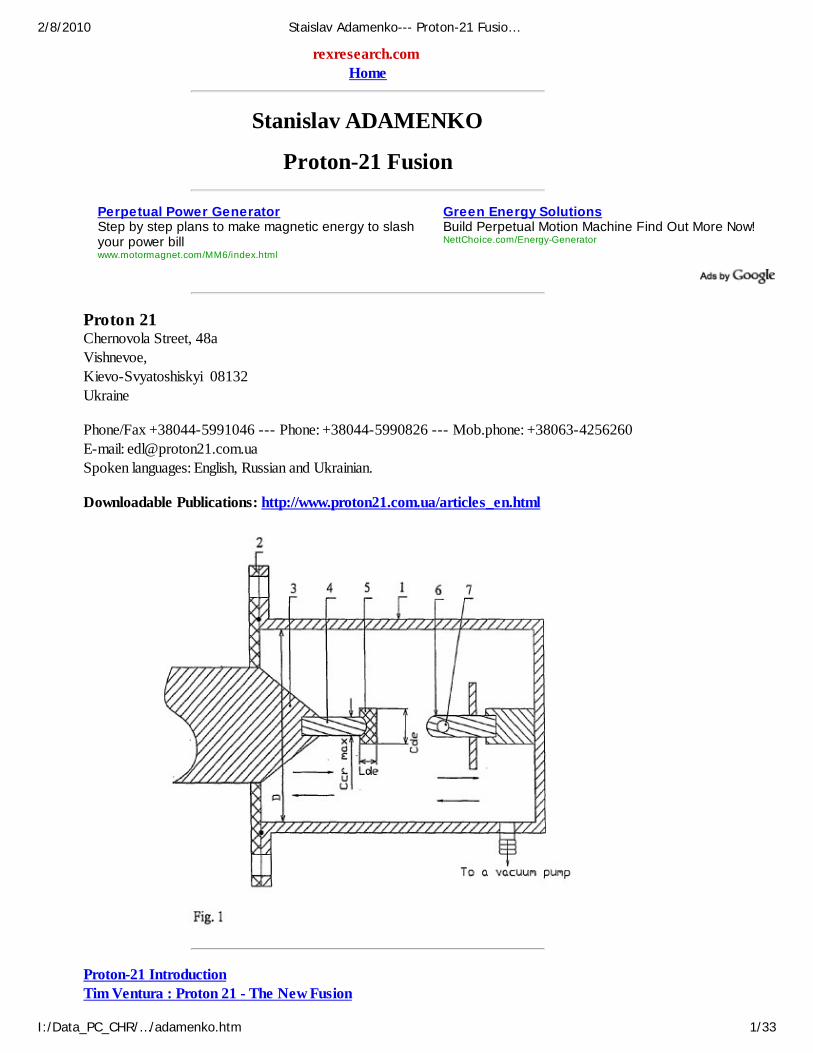
[0123] FIG. 1 is a structural layout diagram of electrodes in the RVD, the adjustable geometricparameters being pointed out;
2/8/2010 Staislav Adamenko--- Proton-21 Fusio…
I:/Data_PC_CHR/…/adamenko.htm 15/33

[0124] FIG. 2 is a block diagram of a pulsed high-voltage power source;
[0125] FIG. 3 is a preferable structure of an axisymmetric plasma cathode (a section along thesymmetry axis);
2/8/2010 Staislav Adamenko--- Proton-21 Fusio…
I:/Data_PC_CHR/…/adamenko.htm 16/33
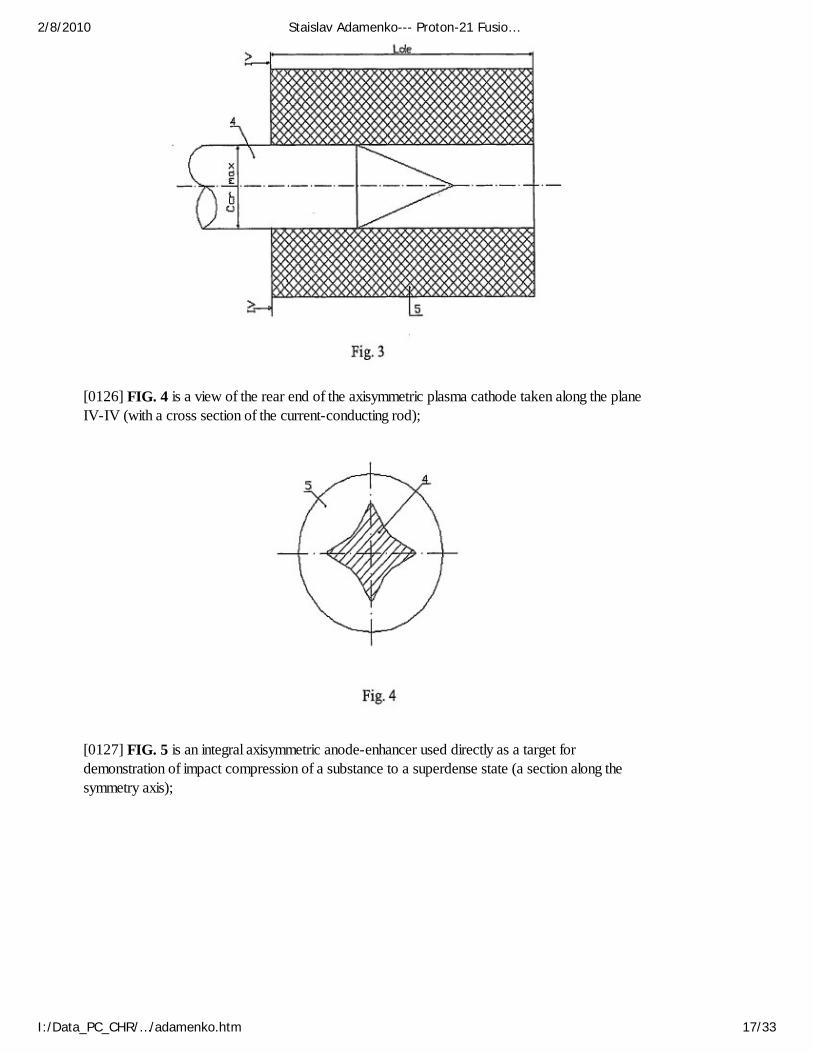
[0126] FIG. 4 is a view of the rear end of the axisymmetric plasma cathode taken along the planeIV-IV (with a cross section of the current-conducting rod);
[0127] FIG. 5 is an integral axisymmetric anode-enhancer used directly as a target fordemonstration of impact compression of a substance to a superdense state (a section along thesymmetry axis);
2/8/2010 Staislav Adamenko--- Proton-21 Fusio…
I:/Data_PC_CHR/…/adamenko.htm 17/33
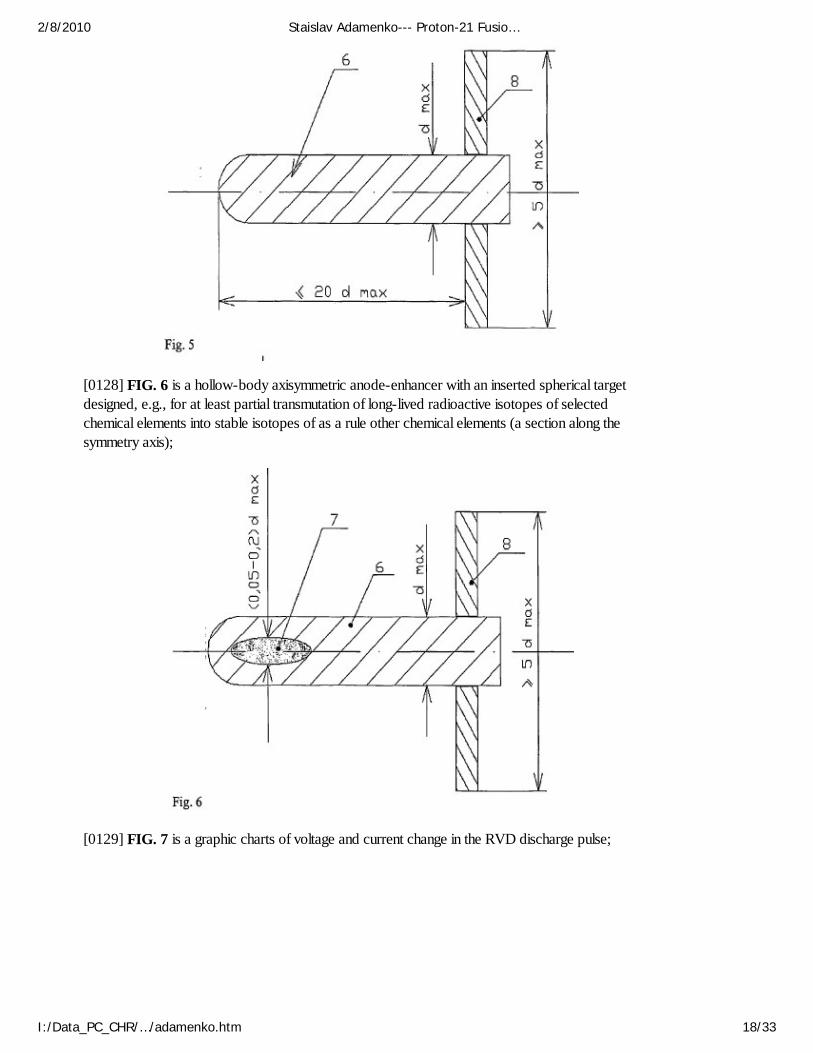
[0128] FIG. 6 is a hollow-body axisymmetric anode-enhancer with an inserted spherical targetdesigned, e.g., for at least partial transmutation of long-lived radioactive isotopes of selectedchemical elements into stable isotopes of as a rule other chemical elements (a section along thesymmetry axis);
[0129] FIG. 7 is a graphic charts of voltage and current change in the RVD discharge pulse;
2/8/2010 Staislav Adamenko--- Proton-21 Fusio…
I:/Data_PC_CHR/…/adamenko.htm 18/33
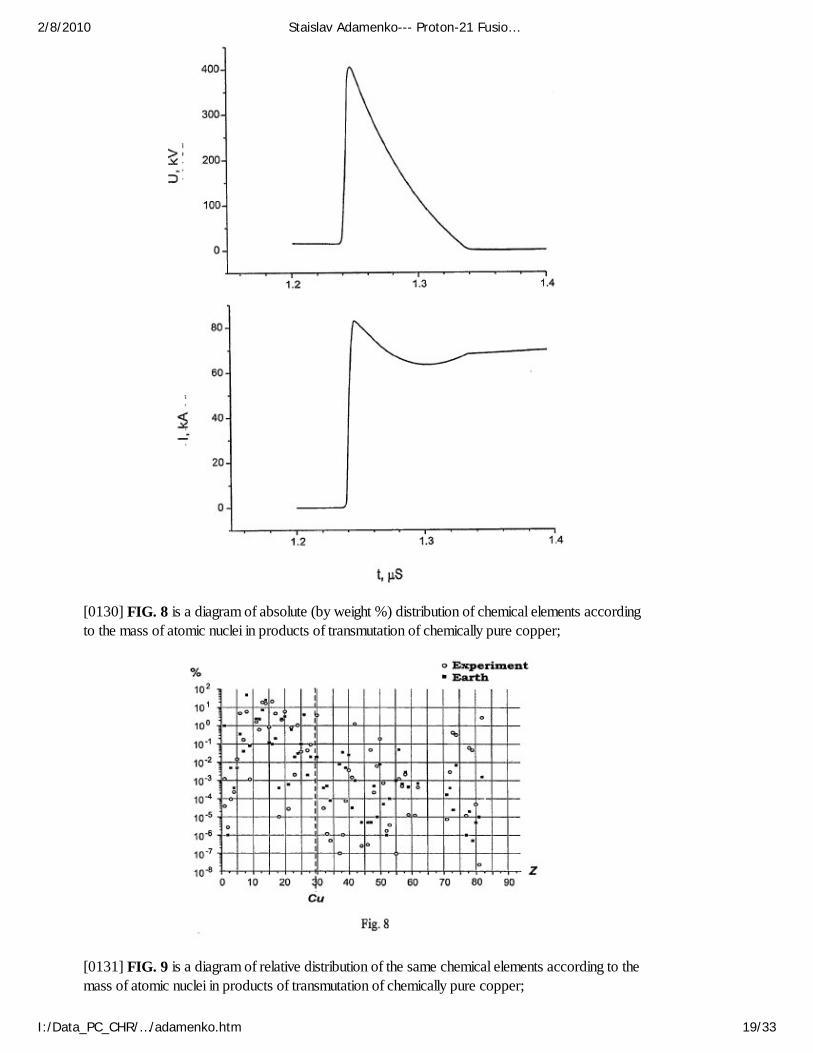
[0130] FIG. 8 is a diagram of absolute (by weight %) distribution of chemical elements accordingto the mass of atomic nuclei in products of transmutation of chemically pure copper;
[0131] FIG. 9 is a diagram of relative distribution of the same chemical elements according to themass of atomic nuclei in products of transmutation of chemically pure copper;
2/8/2010 Staislav Adamenko--- Proton-21 Fusio…
I:/Data_PC_CHR/…/adamenko.htm 19/33

[0132] FIG. 10 is a diagram of absolute (by weight %) distribution of chemical elements accordingto the mass of atomic nuclei in products of transmutation of chemically pure tantalum;
[0133] FIG. 11 is a diagram of relative distribution of the same chemical elements according to themass of atomic nuclei in products of transmutation of chemically pure tantalum;
2/8/2010 Staislav Adamenko--- Proton-21 Fusio…
I:/Data_PC_CHR/…/adamenko.htm 20/33
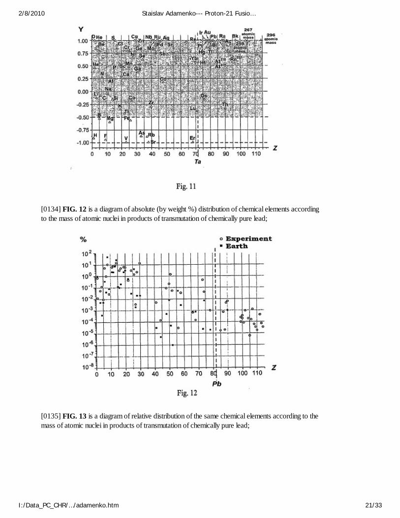
[0134] FIG. 12 is a diagram of absolute (by weight %) distribution of chemical elements accordingto the mass of atomic nuclei in products of transmutation of chemically pure lead;
[0135] FIG. 13 is a diagram of relative distribution of the same chemical elements according to themass of atomic nuclei in products of transmutation of chemically pure lead;
2/8/2010 Staislav Adamenko--- Proton-21 Fusio…
I:/Data_PC_CHR/…/adamenko.htm 21/33

[0136] FIG. 14 is a reference mass spectrum of isotopes of nickel obtained by a study of samplesof natural nickel that coincides with the natural abundance of such isotopes in the Earth's crust;
2/8/2010 Staislav Adamenko--- Proton-21 Fusio…
I:/Data_PC_CHR/…/adamenko.htm 22/33
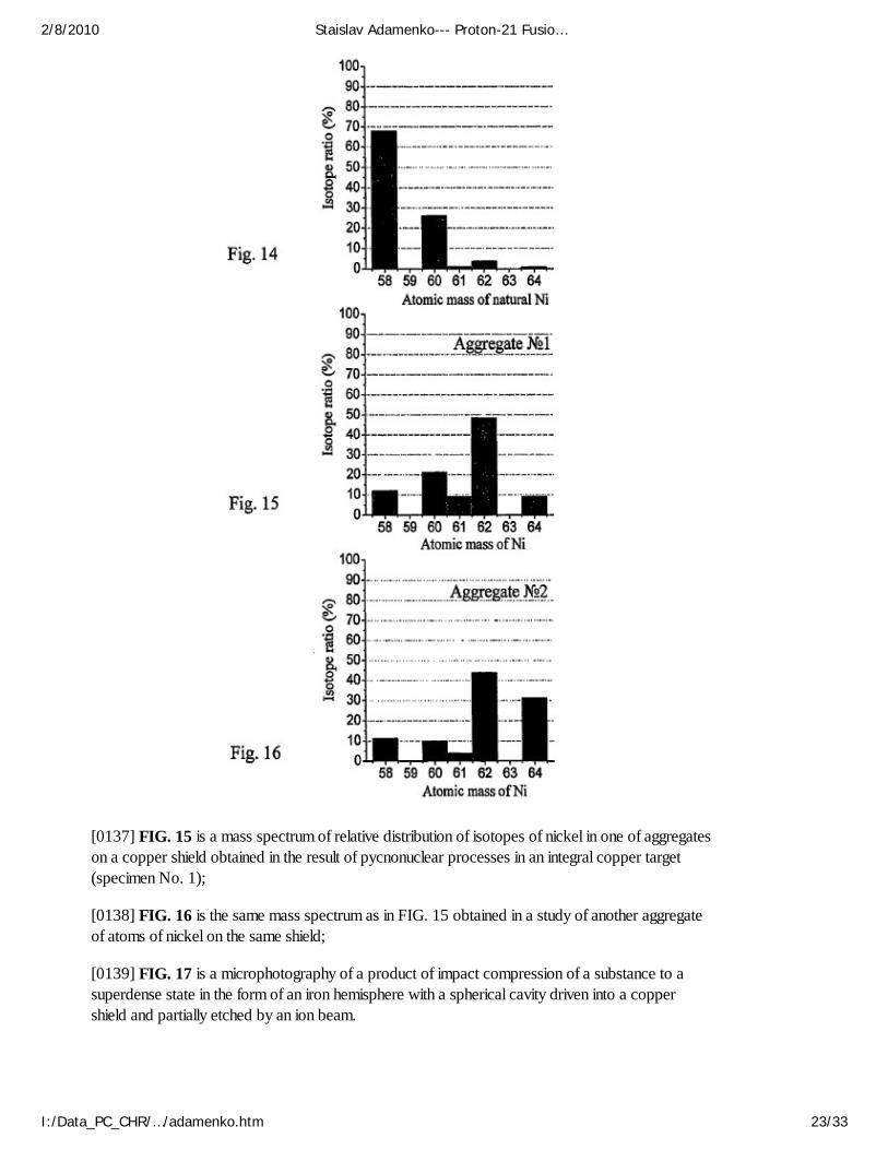
[0137] FIG. 15 is a mass spectrum of relative distribution of isotopes of nickel in one of aggregateson a copper shield obtained in the result of pycnonuclear processes in an integral copper target(specimen No. 1);
[0138] FIG. 16 is the same mass spectrum as in FIG. 15 obtained in a study of another aggregateof atoms of nickel on the same shield;
[0139] FIG. 17 is a microphotography of a product of impact compression of a substance to asuperdense state in the form of an iron hemisphere with a spherical cavity driven into a coppershield and partially etched by an ion beam.
2/8/2010 Staislav Adamenko--- Proton-21 Fusio…
I:/Data_PC_CHR/…/adamenko.htm 23/33

BEST MODE FOR CARRYING OUT THE INVENTION
[0140] The device according to the invention (FIG. 1) is made on the basis of a RVD. The essentialparts thereof are:
[0141] a strong gas-tight housing 1 which is made partly from a current-conducting material (forexample, copper or stainless steel) shaped axisymmetrically to confine a vacuum chamber closed, inthe operation condition, with a dielectric end cover 2 and connected when required via at least onepipe (not shown) to a vacuum pump;
[0142] a non-consumable axisymmetric current-conducting rod 3 preferably circular in the crosssection and preferably tapered in the longitudinal section, rigidly and tightly fixed in the cover 2 andintended for connection of RVD to a pulsed high-voltage power source described below;
[0143] a replaceable (as worn out) axisymmetric plasma cathode comprising:
[0144] a current-conducting rod 4 having its tail fixed in the rod 3 and
[0145] a dielectric end element 5 rigidly connected with the rod 4, said element 5 having the area ofthe working end exceeding the cross-section area of the rod 4;
[0146] an axisymmetric anode-enhancer 6 which can be either integral or including a target 7, themaximum cross-section area of said anode-enhancer being smaller than the area of the emitting
2/8/2010 Staislav Adamenko--- Proton-21 Fusio…
I:/Data_PC_CHR/…/adamenko.htm 24/33
surface of the dielectric end element 5;
[0147] optionally, a shield 8 preferably of current-conducting material is mounted on the tail part ofthe anode-enhancer 6;
[0148] at least one (not shown specially but denoted with pairs of arrows under the contours of theplasma cathode 4, 5 and the anode-enhancer 6) mean for adjusting a gap between the electrodes, i.e. the space between the point of intersection of the end surface of the dielectric element 5 of theplasma cathode with its symmetry axis and similar point at the end of the anode-enhancer 6 bothlying practically along the same geometric axis.
[0149] The RVD pulsed high-voltage power source (FIG. 2) in the simplest case can be a wellknown to those skilled in the art system that includes at least one capacitive or inductive energystorage with at least two plasma (or other) current interrupters. However, preferable are `hybrid`sources of power (see, e.g., 1. P. F. Ottinger, J. Appl. Phys., 56, No. 3, 1984; 2. G. I. Dolgachevet al. Physics of Plasma, 24, No. 12, p. 1078, 1984) which comprise connected in series (FIG. 2):
[0150] an input transformer 9 with means for connection to an industrial power network and a high-voltage output winding,
[0151] a storage LC-circuit 10 comprising suitable (not shown) capacitors and inductors,
[0152] a unit 11 for plasma interruption of discharge current in the LC-circuit comprising a set ofwell known to workers in the art plasma guns symmetrically located in one plane, the number ofwhich (up to 12, in particular) usually being equal to the number of capacitors in the LC-circuit.
[0153] Of course, besides of said power units, the RVD pulsed high-voltage power sources usuallyincorporate means (not shown) for measuring pulse current and voltage, such as at least oneRogovski belt and at least one capacitive voltage divider.
[0154] A source of such type was used for the RVD supply in experiments on compressing asubstance by impact to a superdense state described below. This source could provide thefollowing values of the controlled parameters:
[0155] Mean energy of beam electrons . . . 0.2 to 1.6 MeV
[0156] Electron beam duration . . . not greater 100 ns
[0157] Electron beam power . . . 2.10.sup.9 to 0.75-10.sup.12 W
[0158] High-voltage discharge current . . . 10 kA to 500 kA.
[0159] For effective carrying out of the method of impact compression of a substance, it isrecommended to follow a number of additional conditions when producing individual parts of theRVD and targets.
[0160] Thus, it is important that the distance from the common geometric axis of the plasmacathode 4, 5 and anode-enhancer 6 to the inner side of the current-conducting wall of the housing 1exceed 50d.sub.max, where d.sub.max is a maximum cross-sectional dimension of the anode-enhancer 6.
[0161] It is desirable that the plasma cathode (FIG. 3) has its current-conducting rod 4 pointed anddielectric end element 5 provided with a blind or through opening. This element 5 must be fitted onthe rod 4 with a slight tightness so that the setting part of the rod 4 together with the pointed end be
2/8/2010 Staislav Adamenko--- Proton-21 Fusio…
I:/Data_PC_CHR/…/adamenko.htm 25/33

found inside said opening. The shape of such opening in its cross-section and the cross-section ofthe rod 4 (provided the conditions of axial symmetry be followed) may be not circular (e.g., oval,elliptic, star-like, as shown in FIG. 4, etc.).
[0162] It is also desirable that the perimeter of the rear end of the dielectric element 5 (FIG. 4) atleast in the plane perpendicular to the symmetry axis of the plasma cathode embrace the perimeterof the current-conducting rod 4 with a continuous gap. It is to be understood that this condition canbe provided in various shapes of cross-sectional outline of the rod 4 and element 5.
[0163] It is highly preferable that the dielectric end element 5 of the plasma cathode have adeveloped outer surface, e.g., initially rough, as shown in FIG. 4, or deliberately corrugated at leastin one arbitrary direction. Particularly, element 5 can be used having a shape of an axisymmetricmultiple-pointed star in their cross-sections.
[0164] It is desirable that the minimum cross-sectional dimension C.sub.de min of said element 5 bein the range of (5-10).multidot.c.sub.cr max, and the length I.sub.de be in the range of (10-20).multidot.c.sub.cr max, where c.sub.cr max is a maximum cross-sectional dimension of thecurrent-conducting rod 4.
[0165] Said element 5 of the plasma cathode can be made of any dielectric material, which (at thechosen shape and dimensions) is capable for a breakdown under the chosen working voltage in thegap between the RVD electrodes.
[0166] It is preferable that such material be selected from the group consisting of carbon-chainpolymers with single carbon-to-carbon bonds (e.g., polyethylene, polypropylene etc.), paper-baselaminate or textolite type composite materials with organic binders, ebony wood, natural orsynthetic mica, pure oxides of metals belonging to III-VII groups of the periodic table, inorganicglass, sitall, basalt-fiber felt and ceramic dielectrics.
[0167] As it was mentioned above, the axisymmetric anode-enhancer 6 can be:
[0168] either integral (FIG. 5) and consisting of an arbitrary solid usually current-conducting in itsmass preferably metallic material (including both pure metals and their alloys), e.g., copper,tantalum, lead, etc.;
[0169] or have (FIG. 6) at least a one-layer preferably spherical shell 6 made of preferably current-conducting material and an axisymmetric inserted target 7 tightly fixed in said shell and made of anarbitrary condensed (solid or liquid) substance to be compressed by impact.
[0170] A maximum diameter of the axisymmetric inserted target 7 is preferably selected in therange of (0.05-0.2).multidot.d.sub.max, where d.sub.max is a maximum cross-sectional dimensionof the anode-enhancer 6 as a whole. Irrespective of the geometric shape of the target 7 body, itmust be fixed inside the anode-enhancer 6 so that the center of its surface curvature practicallycoincide with the curvature center of the working surface of the anode enhancer 6. It is veryimportant that dislocation density in the material of the anode-enhancer 6 and in the material of thetarget 7 be as small as possible and that an acoustic contact be provided between these parts.
[0171] Said shield 8, which can be mounted in the tail part of the anode-enhancer 6, is usuallymade from a current-conducting material as a preferably thin-wall body of revolution. The diameterof said shield 8 must be not smaller than 5d.sub.max and it's distance from the working end of theanode-enhancer 6 must be not greater than 20d.sub.max, where d.sub.max is a maximum cross-sectional dimension of the anode-enhancer 6. It is desirable that said shield 8 have a flat or concavesurface at the side of the working end of the anode-enhancer 6 (FIGS. 5 and 6).
2/8/2010 Staislav Adamenko--- Proton-21 Fusio…
I:/Data_PC_CHR/…/adamenko.htm 26/33
[0172] The method for impact compression a substance using the described device usually includes:
[0173] a) connecting the current-conducting rod 4 of the aforesaid plasma cathode to the non-consumable current-conducting rod 3;
[0174] b) producing a set of replaceable axisymmetric anodes-enhancers 6 preferably having theirworking ends rounded in one of the following variants:
[0175] either in the form of integral pieces of the material to be compressed by impact (fortransmutation or any other nuclear transformation),
[0176] or in the form of preferably one-layer shells wherein targets 7 are tightly inserted, saidtargets being made of the material (preliminarily encapsulated, as required) to be compressed byimpact (for transmutation or any other nuclear transformation);
[0177] c) (optionally) fitting at least some of the anodes-enhancers 6 with current-conductingshields 8 made of copper, lead, niobium, tantalum etc.;
[0178] d) placing each next anode-enhancer 6 in the vacuum chamber of the RVD housing 1practically on the same geometric axis with the plasma cathode 4, 5;
[0179] e) adjusting the gap between the working ends of the dielectric end element 5 of the plasmacathode and the anode-enhancer 6 in such a way that the center of curvature of the working surfaceof the anode-enhancer 6 is located inside the focal space of the collectively self-focussing electronbeam at a pulse discharge of the power source via the RVD;
[0180] f) closing the vacuum chamber by fitting the end dielectric cover 2 on a flange of the stronggas-tight current-conducting housing 1 of the RVD;
[0181] g) vacuuming the chamber in the RVD housing 1, which is carried out:
[0182] at least twice prior to the first `shot` upon the target (pumping out the air first and then atleast once blowing down the chamber with clean dry nitrogen and re-vacuuming to the residualpressure of gases not greater than 0.1 Pa), and
[0183] at least once prior to each next `shot`, if the residual pressure exceeds said value;
[0184] h) connecting an external high-voltage power source of the RVD to a power network viathe input transformer 9 and storing the electric energy required for an experiment in the LC-circuit10;
[0185] i) discharging the LC-circuit 10 via the unit 11 for plasma interruption of the current pulse,the non-consumable axisymmetric current-conducting rod 3, the replaceable current-conducting rod4 and the dielectric end element 5 on the RVD anode-enhancer 6 with generation of an electronbeam having the electron energy not less than 0.2 MeV, current density not less than 10.sup.6A/cm.sup.2 (and preferably not more than 10.sup.8 A/cm.sup.2, and more preferably not morethan 10.sup.7 A/cm.sup.2) and duration not greater than 100 ns (and preferably not more than 50ns);
[0186] j) removing of the products obtained after the compression of a portion of the targetsubstance to a superdense state from the vacuum chamber of the RVD housing 1 and studyingthese products by the commonly used techniques.
[0187] The experimental targets were intended to:
2/8/2010 Staislav Adamenko--- Proton-21 Fusio…
I:/Data_PC_CHR/…/adamenko.htm 27/33
[0188] demonstrate the transmutation effect as a result of the impact compression of a substance toa superdense state (integral anodes-enhancers 6 in accordance with FIG. 5); and
[0189] evaluate the possibility of radioactive materials deactivation (hollow-body anode-enhancers6 with inserted target 7 according to FIGS. 1 and 6). As mentioned above, such target 7 must beinserted into the anode-enhancer 6 providing the maximum acoustic transparency of their junctioncontact, and the curvature centers of the working surfaces of the both said components mustcoincide practically.
[0190] The integral anodes-enhancers 6 had average radius of curvature of the working ends in therange of 0.2 to 0.5 mm, as a rule. They were made, particularly, of chemically pure metals, such ascopper, tantalum and lead. Such anodes-enhancers 6 can be stored outdoors. An oxide film thatappears on the surface (especially of copper and lead) does not prevent and, according to someobservations, even enhances their use in accordance with the above-mentioned purposes.
[0191] The inserted targets 7 had a shape of pellets made of available Co.sup.60 isotope andartificial mixtures of Co.sup.56 and Co.sup.58 produced by irradiation of natural nickel on U-120cyclotron in Nuclear Research Institute of National Academy of Sciences of Ukraine.
[0192] The use of such targets required additional shells (not shown) made of polycaprolactam(capron) that are mounted inside the RVD vacuum chambers. These shells enveloped both RVDelectrodes and reduced significantly the risk of the radioactive cobalt precipitation on the walls ofthe housing 1 and the RVD cover 2.
[0193] The initial radioactivity values and those attained after transmutation of utilized cobaltisotopes were controlled by ordinary germanium-lithium gamma-ray detectors.
[0194] More than thousand of adjustment experiments had been carried out prior to beginning ofthe operational experiments on impact compression of a substance to a superdense state. Theresults of adjustment experiments helped to select and more exactly define (taken into account thedimensions of parts 4,5 of the plasma cathode and anode-enhancer 6, and specific parameters ofthe charge) the width of the gap between the RVD electrodes in order to provide hitting of thetarget curvature centers into the focal space of the RVD electron beam.
[0195] The operational experiments were carried out in series. Their number varied in differentseries and ranged from 50 (at transmutation of radioactive cobalt) to several hundreds. All theexperiments had a through numbering.
[0196] The initial data on the used targets, discharge parameters and obtained results wererecorded in logbooks under sequential numbers.
[0197] The shape of voltage and current pulses in the gap between the RVD electrodes and actualduration of the electron beam were checked with current and voltage oscillograms, typical examplesare shown in FIG. 7. These and many other oscillograms demonstrate that the duration of theelectron beam does not exceed 100 ns.
[0198] It is important to note that the electron beam current (despite a sharp voltage drop on theRVD plasma cathode) only slightly decreases as compared to the peak value. This proves theefficiency of usage of the plasma cathodes 4,5.
[0199] After statistical processing of the results of the adjustment experiments with regard to thecontrolled parameters of the electron beam generation process approximate dimensions for the
2/8/2010 Staislav Adamenko--- Proton-21 Fusio…
I:/Data_PC_CHR/…/adamenko.htm 28/33
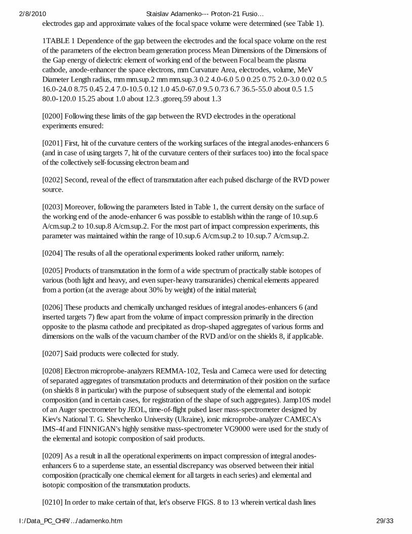
electrodes gap and approximate values of the focal space volume were determined (see Table 1).
1TABLE 1 Dependence of the gap between the electrodes and the focal space volume on the restof the parameters of the electron beam generation process Mean Dimensions of the Dimensions ofthe Gap energy of dielectric element of working end of the between Focal beam the plasmacathode, anode-enhancer the space electrons, mm Curvature Area, electrodes, volume, MeVDiameter Length radius, mm mm.sup.2 mm mm.sup.3 0.2 4.0-6.0 5.0 0.25 0.75 2.0-3.0 0.02 0.516.0-24.0 8.75 0.45 2.4 7.0-10.5 0.12 1.0 45.0-67.0 9.5 0.73 6.7 36.5-55.0 about 0.5 1.580.0-120.0 15.25 about 1.0 about 12.3 .gtoreq.59 about 1.3
[0200] Following these limits of the gap between the RVD electrodes in the operationalexperiments ensured:
[0201] First, hit of the curvature centers of the working surfaces of the integral anodes-enhancers 6(and in case of using targets 7, hit of the curvature centers of their surfaces too) into the focal spaceof the collectively self-focussing electron beam and
[0202] Second, reveal of the effect of transmutation after each pulsed discharge of the RVD powersource.
[0203] Moreover, following the parameters listed in Table 1, the current density on the surface ofthe working end of the anode-enhancer 6 was possible to establish within the range of 10.sup.6A/cm.sup.2 to 10.sup.8 A/cm.sup.2. For the most part of impact compression experiments, thisparameter was maintained within the range of 10.sup.6 A/cm.sup.2 to 10.sup.7 A/cm.sup.2.
[0204] The results of all the operational experiments looked rather uniform, namely:
[0205] Products of transmutation in the form of a wide spectrum of practically stable isotopes ofvarious (both light and heavy, and even super-heavy transuranides) chemical elements appearedfrom a portion (at the average about 30% by weight) of the initial material;
[0206] These products and chemically unchanged residues of integral anodes-enhancers 6 (andinserted targets 7) flew apart from the volume of impact compression primarily in the directionopposite to the plasma cathode and precipitated as drop-shaped aggregates of various forms anddimensions on the walls of the vacuum chamber of the RVD and/or on the shields 8, if applicable.
[0207] Said products were collected for study.
[0208] Electron microprobe-analyzers REMMA-102, Tesla and Cameca were used for detectingof separated aggregates of transmutation products and determination of their position on the surface(on shields 8 in particular) with the purpose of subsequent study of the elemental and isotopiccomposition (and in certain cases, for registration of the shape of such aggregates). Jamp10S modelof an Auger spectrometer by JEOL, time-of-flight pulsed laser mass-spectrometer designed byKiev's National T. G. Shevchenko University (Ukraine), ionic microprobe-analyzer CAMECA'sIMS-4f and FINNIGAN's highly sensitive mass-spectrometer VG9000 were used for the study ofthe elemental and isotopic composition of said products.
[0209] As a result in all the operational experiments on impact compression of integral anodes-enhancers 6 to a superdense state, an essential discrepancy was observed between their initialcomposition (practically one chemical element for all targets in each series) and elemental andisotopic composition of the transmutation products.
[0210] In order to make certain of that, let's observe FIGS. 8 to 13 wherein vertical dash lines
2/8/2010 Staislav Adamenko--- Proton-21 Fusio…
I:/Data_PC_CHR/…/adamenko.htm 29/33
indicate the charge of an initial chemical element's nucleus.
[0211] It should be noted, that the isotopes of chemical elements which were not present in theinitial material of the target but appeared in the products of transmutation are indicated in FIGS. 8,10 and 12:
[0212] by light circles according to their concentration in said products of pycnonuclear processes,
[0213] by black squares according to their concentration in the Earth's crust.
[0214] Nuclei charges and percentage by weight of these isotopes are easy to determine using thenumerical data on the X and Y axis respectively.
[0215] With light triangles and adjacent chemical symbols, FIGS. 9, 11 and 13 show relativedeviations Y of concentrations (% by weight) of certain chemical elements from natural abundanceratio that were calculated by formula: 1 A - B A + B = Y , where :
[0216] A is a ratio of a certain isotope of a certain chemical element in the products oftransmutation, and
[0217] B is a ratio of the same isotope of the same chemical element in the Earth's crust.
[0218] As it's clearly seen from FIGS. 8, 10 and 12, in the process of transmutation of initialcopper, tantalum and lead appears a wide spectrum of isotopes of various chemical elements withsmaller and greater Z nuclear charges in comparison to the nuclear charge of parent element.
[0219] However, the greater is the nuclear charge of the target material the higher is the probabilityof production of stable transuranides (including those not identified yet) with atomic mass of greaterthan 250 atomic mass units (and in some to be checked cases, up to 600 amu and greater).
[0220] The presence of atoms having such masses was detected at first by the method of ion massspectrometry and then was proved by well known methods of Rutherford alpha and proton back-scattering.
[0221] Moreover, FIGS. 9, 11 and 13 clearly show that concentrations of substantial portion ofchemical elements in transmutation products statistically reliably exceed (more than in three timesand some elements in 5-10 and more times) their normal concentrations in the Earth's crust (seeareas marked out with dark colour within the range of Y values from 0.5 to 1.0). This obviouslyproves the artificial origin of such products of pycnonuclear processes.
[0222] As for changes in elemental and isotopic composition, similar results were obtained also inexperiments with targets of radioactive cobalt. However, in these cases the main attention was paidto reduction in radioactivity in products of the target spread due to transmutation of radioactivenuclei of cobalt into non-radioactive isotopes of other chemical elements, in those part of the targetwhich was in the focal space.
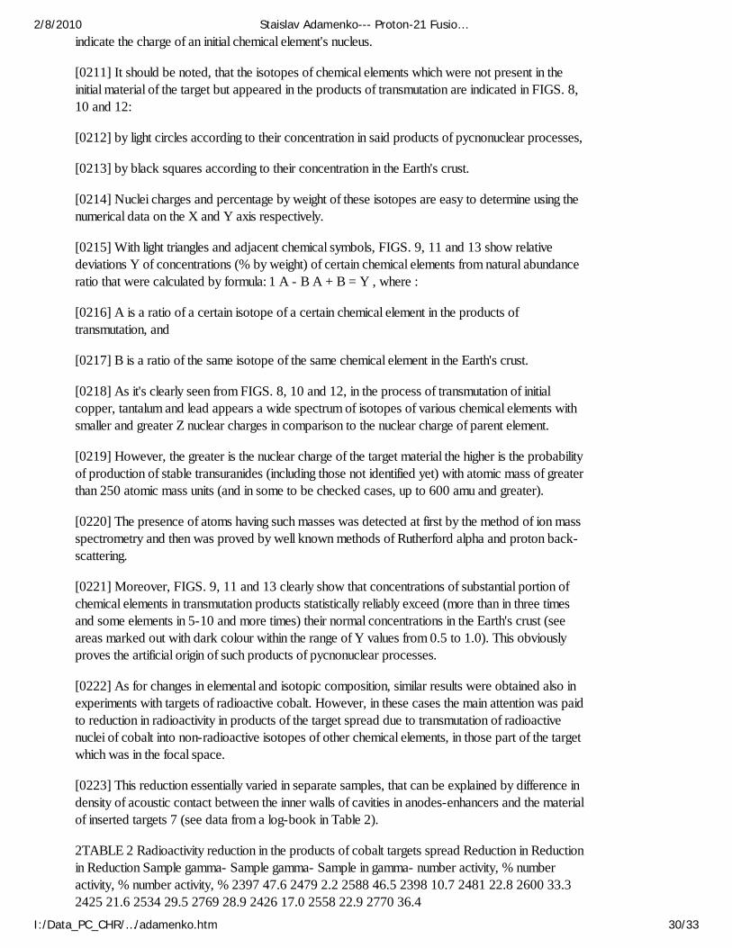
[0223] This reduction essentially varied in separate samples, that can be explained by difference indensity of acoustic contact between the inner walls of cavities in anodes-enhancers and the materialof inserted targets 7 (see data from a log-book in Table 2).
2TABLE 2 Radioactivity reduction in the products of cobalt targets spread Reduction in Reductionin Reduction Sample gamma- Sample gamma- Sample in gamma- number activity, % numberactivity, % number activity, % 2397 47.6 2479 2.2 2588 46.5 2398 10.7 2481 22.8 2600 33.32425 21.6 2534 29.5 2769 28.9 2426 17.0 2558 22.9 2770 36.4
2/8/2010 Staislav Adamenko--- Proton-21 Fusio…
I:/Data_PC_CHR/…/adamenko.htm 30/33
[0224] Thus, sample No. 2479 was deactivated only by 2.2% whereas sample No. 2397 and No.2588 lost more than 45% of their activity in the result of transmutation.
[0225] Further, as it was definitely established, the distribution of isotopes in conglomerates ofatoms of each chemical element detected in products of pycnonuclear processes is essentiallydiffered from the distribution of the same isotopes in the Earth's crust.
[0226] The brightest example of such drastic discrepancy is the difference between the normaldistribution of isotopes of nickel in natural samples (FIG. 14) and in two aggregates of nickel atomsproduced by transmutation of copper targets (FIGS. 15 and 16). Thus, the content of Ni.sup.58isotope is up to 70% in the mass of natural nickel, while the proportion of Ni.sup.58 in products ofcopper transmutation (with Cu.sup.63 isotope dominating in the target) exceeds 10%. Similarly,content of Ni.sup.60 isotope essentially (usually twice) decreased whereas content of Ni.sup.62sharply increased.
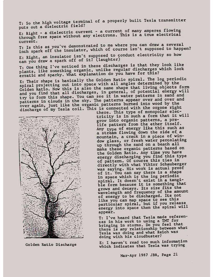
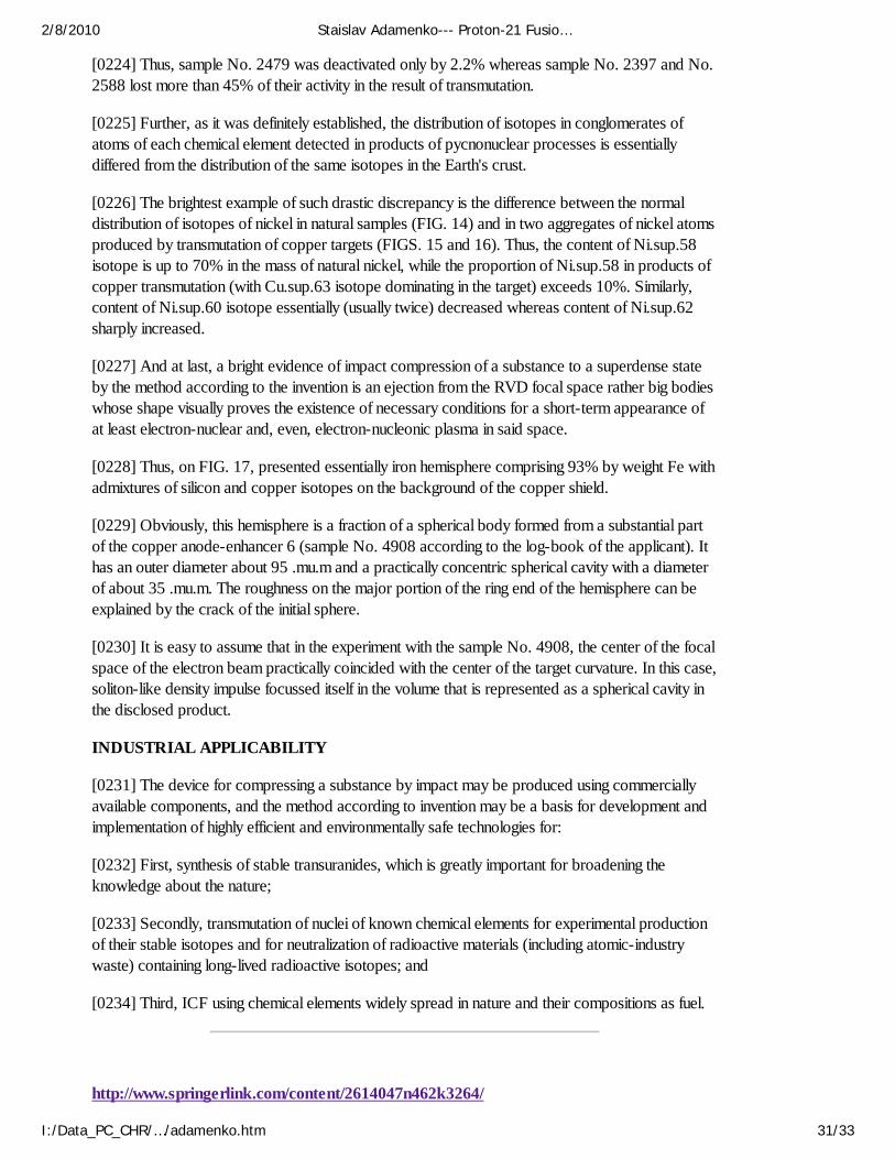
[0227] And at last, a bright evidence of impact compression of a substance to a superdense stateby the method according to the invention is an ejection from the RVD focal space rather big bodieswhose shape visually proves the existence of necessary conditions for a short-term appearance ofat least electron-nuclear and, even, electron-nucleonic plasma in said space.
[0228] Thus, on FIG. 17, presented essentially iron hemisphere comprising 93% by weight Fe withadmixtures of silicon and copper isotopes on the background of the copper shield.
[0229] Obviously, this hemisphere is a fraction of a spherical body formed from a substantial partof the copper anode-enhancer 6 (sample No. 4908 according to the log-book of the applicant). Ithas an outer diameter about 95 .mu.m and a practically concentric spherical cavity with a diameterof about 35 .mu.m. The roughness on the major portion of the ring end of the hemisphere can beexplained by the crack of the initial sphere.
[0230] It is easy to assume that in the experiment with the sample No. 4908, the center of the focalspace of the electron beam practically coincided with the center of the target curvature. In this case,soliton-like density impulse focussed itself in the volume that is represented as a spherical cavity inthe disclosed product.
INDUSTRIAL APPLICABILITY
[0231] The device for compressing a substance by impact may be produced using commerciallyavailable components, and the method according to invention may be a basis for development andimplementation of highly efficient and environmentally safe technologies for:
[0232] First, synthesis of stable transuranides, which is greatly important for broadening theknowledge about the nature;
[0233] Secondly, transmutation of nuclei of known chemical elements for experimental productionof their stable isotopes and for neutralization of radioactive materials (including atomic-industrywaste) containing long-lived radioactive isotopes; and
[0234] Third, ICF using chemical elements widely spread in nature and their compositions as fuel.
http://www.springerlink.com/content/2614047n462k3264/
2/8/2010 Staislav Adamenko--- Proton-21 Fusio…
I:/Data_PC_CHR/…/adamenko.htm 31/33

Technical Physics Letters 27(8): 671-673 (August 2001)
Vacuum Electric Discharge Initiated by Accelerated Nanoparticles
S. V. Adamenko (1, 2), P. A. Bereznyak (1, 2), I. M. Mikhailovskii (1, 2), V. A. Stratienko (1, 2),N. G. Tolmachev (1, 2), A. S. Adamenko (1, 2) and T. I. Mazilova (1, 2)
(1) Kharkov Physicotechnical Institute, National Scientific Center, Kharkov, Ukraine; (2) Laboratory of Electrodynamic Investigations, ENRAN Company, Kiev, Ukraine
Abstract --- A static breakdown induced by the impact of particles detached from a point anodein a strong electric field, corresponding to the athermal field evaporation threshold, was studied byfield ion microscopy. Under these conditions, the particle size threshold for the vacuum dischargeinitiation decreases by one order of magnitude as compared to the case of flat electrodes and fallswithin a nanometer range of the average radius of bombarding charged particles. The thresholdenergies of particles initiating a static electric discharge also exhibit a significant decrease.
http://www.springerlink.com/content/y740700541102508/
Foundations of Physics Letters 19 (1 / Feb 2006 ), pp 21-36
Key words: neutronization - protonization - Coulomb interaction - degenerate electron gas -superheavy nuclei synthesis
V. Adamenko (1) and V. I. Vysotskii (2)
(1) Electrodynamics Laboratory “Proton-21,”, Kyiv, Ukraine (2) Shevchenko Kyiv National University, Faculty of Radiophysics, Kyiv, Ukraine
Abstract --- We consider the peculiarities of the fundamental nuclear transformations running bothin the shell of a heavy star compressed by the strong gravitational field and during the laboratoryelectron-nucleus collapse where the compression occurs at the expense of the electron-nucleusinteraction in a volume occupied by a degenerate electron gas, define their analogs, and analyze thedifferences.
It is shown that the account of relativistic and nonlinear corrections to the Coulomb electron-nucleusinteraction gives the possibility to realize two alternative ways for the evolution of the star matterwhich depend on both the rate of compression upon the gravitational collapse and the initial isotopecomposition of a star on the stage preceding the collapse.
Upon the relatively slow compression of a heavy star in the process of gravitational collapse afterthe attainment of the threshold electron density, there occur the stage-by-stage neutronization ofnuclei and the formation of a neutron star with a great concentration of neutrons and a lowconcentration of protons and electrons. This process is characterized by the presence of a boundedinterval of the density of a relativistic degenerate gas of electrons (“the neutronization corridor”), inthe scope of which the neutronization runs with a decrease in the Fermi energy and the release ofenergy in the form of fast neutrinos.
At a higher electron density, the process of protonization becomes energy-gained. In this case, anincrease in both the charge of nuclei and the concentration of degenerate electrons causes thecontinuous increase in the binding energy of electrons and nuclei which turns out to be moresignificant than the increase in the Fermi energy of electrons. The transition of nuclei through “the
2/8/2010 Staislav Adamenko--- Proton-21 Fusio…
I:/Data_PC_CHR/…/adamenko.htm 32/33

neutronization corridor” into “the protonization zone”, which ranges up to the nuclear density of asubstance, is possible only in the case of a very fast compression of a heavy star. Such a processleads to the possibility of the formation of proton stars with a very small residual concentration ofneutrons and a great (nuclear) concentration of protons and electrons.
It is shown that analogous effects can be realized during the laboratory electron-nucleus collapse.Due to a microscopic size of the collapse zone, a great velocity of its formation, and a relatively lowrate of neutronization, the passage of the electron-nucleus substance through “the neutronizationcorridor” weakly affects its state. In this case, the main mechanism of transformations is the processof protonization with a simultaneous increase in the concentration of degenerate electrons.
Contact Information S. V. Adamenko Email: [email protected]
2/8/2010 Staislav Adamenko--- Proton-21 Fusio…
I:/Data_PC_CHR/…/adamenko.htm 33/33

American Antigravity.Com Page 1 of 15

By Tim Ventura & Dr. Stanislav Adamenko, August 13th, 2006 By subjecting a copper electrode to a gigawatt pulse of energy, Dr. Stanislav Adamenko believes that he’s found a new form of fusion that occurs inside a millimeter sized plasma that forms in the electrode. Has Adamenko finally cracked the code of solid-state fusion, and what potential for future energy does it hold? He joins us for the inside story on Proton 21’s research into creating “The New Fusion”… AAG: I’d like to start out by asking you about the background & history of the Proton 21 Electrodynamics Laboratory. How were you founded, and what inspired you to begin conducting fusion research?
Target Samples: Color-enhanced views of several Proton-21 CTS target samples.
Adamenko: It’s difficult to write a concise history of Proton 21, because it begins, at least for me, as early as half a century ago. It all began with a number of insignificant events that at first appeared to be completely unrelated, but eventually became the inspiration for today’s research. Without those synchronicities, I doubt that Proton 21 would exist today… We’re working on assembling a detailed history of Proton 21, which will appear in the introductory section of a book we’re publishing about our research through one of the big European publishing houses. Since that project is really going to provide the most comprehensive view of our work, I’ll just review some of the main stages of our research in our interview today. At the end of 1958, when I was a very young man, I first became acquainted with the problem of controlled thermonuclear synthesis (CTS). This problem seized my imagination. I strongly wanted to believe in the existence of a simple and elegant solution, similar to the natural mechanisms in the synthesis of optimum structures. The search for a solution took many years. By the end of 1979, as a result of my work on a dissertation devoted to analytical methods for the synthesis of multidimensional dynamical systems with optimum stability, I arrived at a realization that allowed me to see the conceptual unity of two
American Antigravity.Com Page 2 of 15
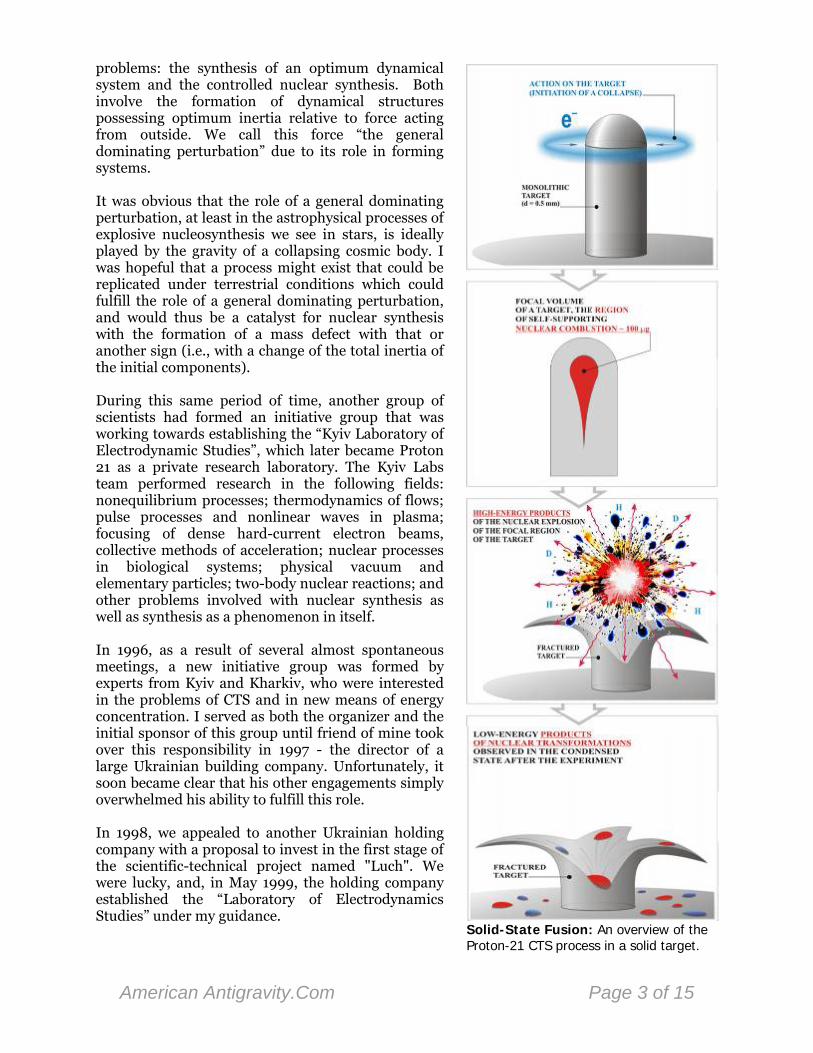
problems: the synthesis of an optimum dynamical system and the controlled nuclear synthesis. Both involve the formation of dynamical structures possessing optimum inertia relative to force acting from outside. We call this force “the general dominating perturbation” due to its role in forming systems.
Solid-State Fusion: An overview of the Proton-21 CTS process in a solid target.
It was obvious that the role of a general dominating perturbation, at least in the astrophysical processes of explosive nucleosynthesis we see in stars, is ideally played by the gravity of a collapsing cosmic body. I was hopeful that a process might exist that could be replicated under terrestrial conditions which could fulfill the role of a general dominating perturbation, and would thus be a catalyst for nuclear synthesis with the formation of a mass defect with that or another sign (i.e., with a change of the total inertia of the initial components). During this same period of time, another group of scientists had formed an initiative group that was working towards establishing the “Kyiv Laboratory of Electrodynamic Studies”, which later became Proton 21 as a private research laboratory. The Kyiv Labs team performed research in the following fields: nonequilibrium processes; thermodynamics of flows; pulse processes and nonlinear waves in plasma; focusing of dense hard-current electron beams, collective methods of acceleration; nuclear processes in biological systems; physical vacuum and elementary particles; two-body nuclear reactions; and other problems involved with nuclear synthesis as well as synthesis as a phenomenon in itself. In 1996, as a result of several almost spontaneous meetings, a new initiative group was formed by experts from Kyiv and Kharkiv, who were interested in the problems of CTS and in new means of energy concentration. I served as both the organizer and the initial sponsor of this group until friend of mine took over this responsibility in 1997 - the director of a large Ukrainian building company. Unfortunately, it soon became clear that his other engagements simply overwhelmed his ability to fulfill this role. In 1998, we appealed to another Ukrainian holding company with a proposal to invest in the first stage of the scientific-technical project named "Luch". We were lucky, and, in May 1999, the holding company established the “Laboratory of Electrodynamics Studies” under my guidance.
American Antigravity.Com Page 3 of 15
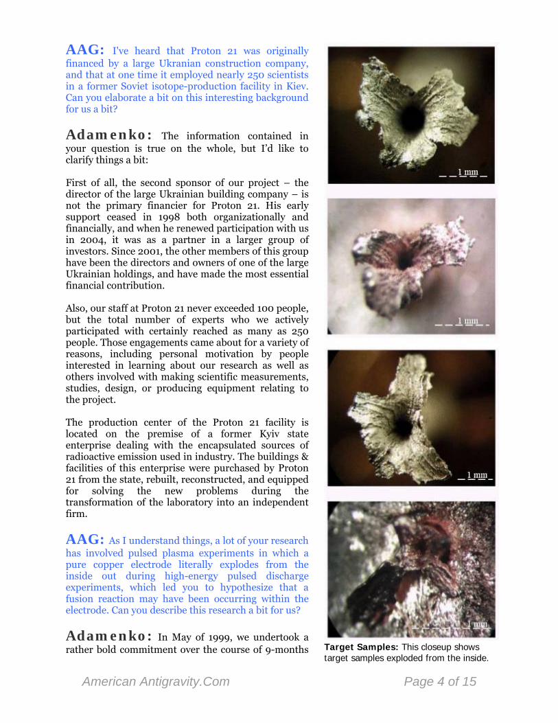
AAG: I've heard that Proton 21 was originally financed by a large Ukranian construction company, and that at one time it employed nearly 250 scientists in a former Soviet isotope-production facility in Kiev. Can you elaborate a bit on this interesting background for us a bit?
Target Samples: This closeup shows target samples exploded from the inside.
Adamenko: The information contained in your question is true on the whole, but I’d like to clarify things a bit: First of all, the second sponsor of our project – the director of the large Ukrainian building company – is not the primary financier for Proton 21. His early support ceased in 1998 both organizationally and financially, and when he renewed participation with us in 2004, it was as a partner in a larger group of investors. Since 2001, the other members of this group have been the directors and owners of one of the large Ukrainian holdings, and have made the most essential financial contribution. Also, our staff at Proton 21 never exceeded 100 people, but the total number of experts who we actively participated with certainly reached as many as 250 people. Those engagements came about for a variety of reasons, including personal motivation by people interested in learning about our research as well as others involved with making scientific measurements, studies, design, or producing equipment relating to the project. The production center of the Proton 21 facility is located on the premise of a former Kyiv state enterprise dealing with the encapsulated sources of radioactive emission used in industry. The buildings & facilities of this enterprise were purchased by Proton 21 from the state, rebuilt, reconstructed, and equipped for solving the new problems during the transformation of the laboratory into an independent firm.
AAG: As I understand things, a lot of your research has involved pulsed plasma experiments in which a pure copper electrode literally explodes from the inside out during high-energy pulsed discharge experiments, which led you to hypothesize that a fusion reaction may have been occurring within the electrode. Can you describe this research a bit for us?
Adamenko: In May of 1999, we undertook a rather bold commitment over the course of 9-months
American Antigravity.Com Page 4 of 15
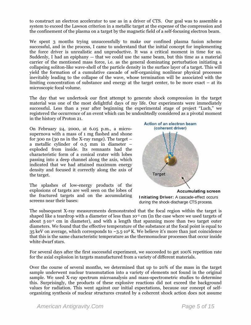
to construct an electron accelerator to use as in a driver of CTS. Our goal was to assemble a system to exceed the Lawson criterion in a metallic target at the expense of the compression and the confinement of the plasma on a target by the magnetic field of a self-focusing electron beam. We spent 3 months trying unsuccessfully to make our confined plasma fusion scheme successful, and in the process, I came to understand that the initial concept for implementing the force driver is unrealistic and unproductive. It was a critical moment in time for us. Suddenly, I had an epiphany -- that we could use the same beam, but this time as a material carrier of the mentioned mass force, i.e. as the general dominating perturbation initiating a collapsing soliton-like wave-shell of the particle density in the surface layer of a target. This will yield the formation of a cumulative cascade of self-organizing nonlinear physical processes inevitably leading to the collapse of the wave, whose termination will be associated with the limiting concentration of substance and energy at the target center, to be more exact – at its microscopic focal volume.
Initiating Driver: A cascade-effect occurs during the shock-discharge CTS process.
The day that we undertook our first attempt to generate shock compression in the target material was one of the most delightful days of my life. Our experiments were immediately successful. Less than a year after beginning the experimental stage of project “Luch,” we registered the occurrence of an event which can be undoubtedly considered as a pivotal moment in the history of Proton 21. On February 24, 2000, at 6.05 p.m., a micro-supernova with a mass of 1 mg flashed and shone for 300 ns (30 ns in the X-ray range). The target – a metallic cylinder of 0.5 mm in diameter –exploded from inside. Its remnants had the characteristic form of a conical crater with lobes passing into a deep channel along the axis, which indicated that we had attained maximum energy density and focused it correctly along the axis of the target. The splashes of low-energy products of the explosions of targets are well seen on the lobes of the fractured targets and on the accumulating screens near their bases: The subsequent X-ray measurements demonstrated that the focal region within the target is shaped like a teardrop with a diameter of less than 10-2 cm (in the case where we used targets of about 5·10-2 cm in diameter), and with a length that spanning more than two target outer diameters. We found that the effective temperature of the substance at the focal point is equal to 35 keV on average, which corresponds to ~3.5·108 K. We believe it’s more than just coincidence that this is the same characteristic temperature as the thermonuclear processes that occur inside white dwarf stars. For several days after the first successful experiment, we succeeded to get 100% repetition rate for the axial explosion in targets manufactured from a variety of different materials. Over the course of several months, we determined that up to 20% of the mass in the target sample underwent nuclear transmutation into a variety of elements not found in the original sample. We used X-ray spectrum microanalysis and mass-spectrometric studies to determine this. Surprisingly, the products of these explosive reactions did not exceed the background values for radiation. This went against our initial expectations, because our concept of self-organizing synthesis of nuclear structures created by a coherent shock action does not assume
American Antigravity.Com Page 5 of 15
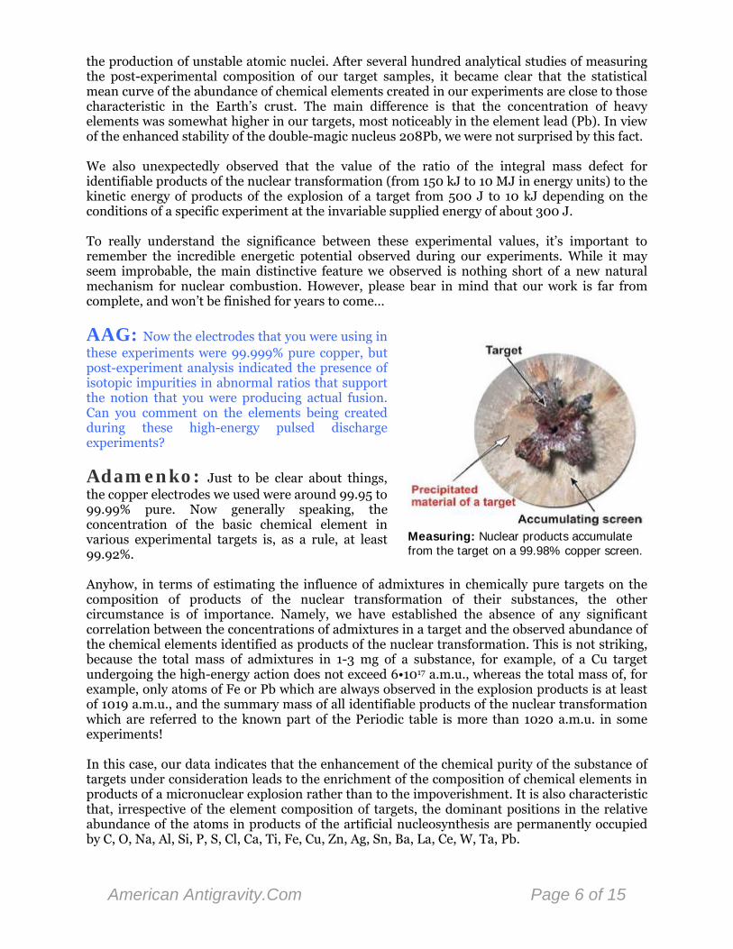
the production of unstable atomic nuclei. After several hundred analytical studies of measuring the post-experimental composition of our target samples, it became clear that the statistical mean curve of the abundance of chemical elements created in our experiments are close to those characteristic in the Earth’s crust. The main difference is that the concentration of heavy elements was somewhat higher in our targets, most noticeably in the element lead (Pb). In view of the enhanced stability of the double-magic nucleus 208Pb, we were not surprised by this fact. We also unexpectedly observed that the value of the ratio of the integral mass defect for identifiable products of the nuclear transformation (from 150 kJ to 10 MJ in energy units) to the kinetic energy of products of the explosion of a target from 500 J to 10 kJ depending on the conditions of a specific experiment at the invariable supplied energy of about 300 J. To really understand the significance between these experimental values, it’s important to remember the incredible energetic potential observed during our experiments. While it may seem improbable, the main distinctive feature we observed is nothing short of a new natural mechanism for nuclear combustion. However, please bear in mind that our work is far from complete, and won’t be finished for years to come…
AAG: Now the electrodes that you were using in these experiments were 99.999% pure copper, but post-experiment analysis indicated the presence of isotopic impurities in abnormal ratios that support the notion that you were producing actual fusion. Can you comment on the elements being created during these high-energy pulsed discharge experiments?
Measuring: Nuclear products accumulate from the target on a 99.98% copper screen.
Adamenko: Just to be clear about things, the copper electrodes we used were around 99.95 to 99.99% pure. Now generally speaking, the concentration of the basic chemical element in various experimental targets is, as a rule, at least 99.92%. Anyhow, in terms of estimating the influence of admixtures in chemically pure targets on the composition of products of the nuclear transformation of their substances, the other circumstance is of importance. Namely, we have established the absence of any significant correlation between the concentrations of admixtures in a target and the observed abundance of the chemical elements identified as products of the nuclear transformation. This is not striking, because the total mass of admixtures in 1-3 mg of a substance, for example, of a Cu target undergoing the high-energy action does not exceed 6•1017 a.m.u., whereas the total mass of, for example, only atoms of Fe or Pb which are always observed in the explosion products is at least of 1019 a.m.u., and the summary mass of all identifiable products of the nuclear transformation which are referred to the known part of the Periodic table is more than 1020 a.m.u. in some experiments! In this case, our data indicates that the enhancement of the chemical purity of the substance of targets under consideration leads to the enrichment of the composition of chemical elements in products of a micronuclear explosion rather than to the impoverishment. It is also characteristic that, irrespective of the element composition of targets, the dominant positions in the relative abundance of the atoms in products of the artificial nucleosynthesis are permanently occupied by C, O, Na, Al, Si, P, S, Cl, Ca, Ti, Fe, Cu, Zn, Ag, Sn, Ba, La, Ce, W, Ta, Pb.
American Antigravity.Com Page 6 of 15
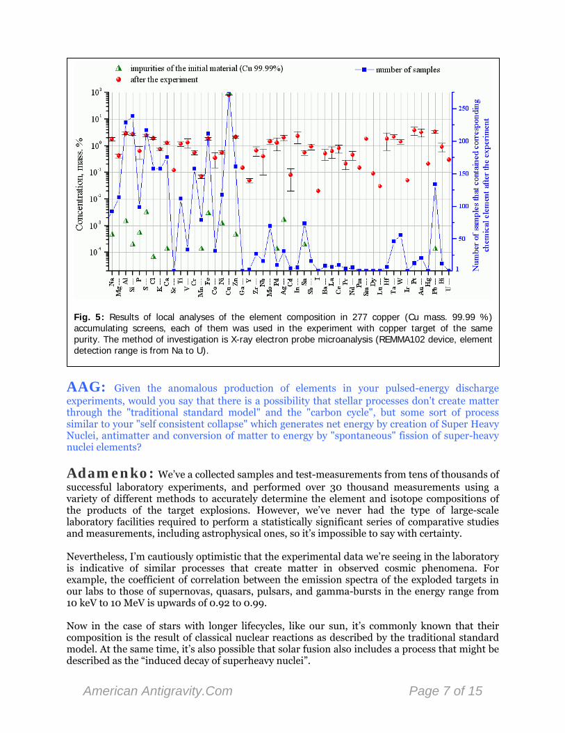
Fig. 5: Results of local analyses of the element composition in 277 copper (Cu mass. 99.99 %) accumulating screens, each of them was used in the experiment with copper target of the same purity. The method of investigation is X-ray electron probe microanalysis (REMMA102 device, element detection range is from Na to U).
AAG: Given the anomalous production of elements in your pulsed-energy discharge experiments, would you say that there is a possibility that stellar processes don't create matter through the "traditional standard model" and the "carbon cycle", but some sort of process similar to your "self consistent collapse" which generates net energy by creation of Super Heavy Nuclei, antimatter and conversion of matter to energy by "spontaneous" fission of super-heavy nuclei elements?
Adamenko: We’ve a collected samples and test-measurements from tens of thousands of successful laboratory experiments, and performed over 30 thousand measurements using a variety of different methods to accurately determine the element and isotope compositions of the products of the target explosions. However, we’ve never had the type of large-scale laboratory facilities required to perform a statistically significant series of comparative studies and measurements, including astrophysical ones, so it’s impossible to say with certainty. Nevertheless, I’m cautiously optimistic that the experimental data we’re seeing in the laboratory is indicative of similar processes that create matter in observed cosmic phenomena. For example, the coefficient of correlation between the emission spectra of the exploded targets in our labs to those of supernovas, quasars, pulsars, and gamma-bursts in the energy range from 10 keV to 10 MeV is upwards of 0.92 to 0.99. Now in the case of stars with longer lifecycles, like our sun, it’s commonly known that their composition is the result of classical nuclear reactions as described by the traditional standard model. At the same time, it’s also possible that solar fusion also includes a process that might be described as the “induced decay of superheavy nuclei”.
American Antigravity.Com Page 7 of 15
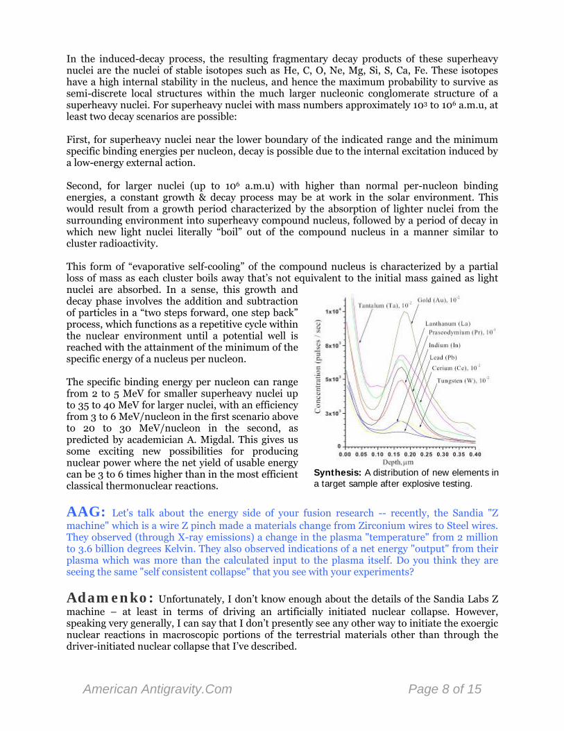
In the induced-decay process, the resulting fragmentary decay products of these superheavy nuclei are the nuclei of stable isotopes such as He, C, O, Ne, Mg, Si, S, Ca, Fe. These isotopes have a high internal stability in the nucleus, and hence the maximum probability to survive as semi-discrete local structures within the much larger nucleonic conglomerate structure of a superheavy nuclei. For superheavy nuclei with mass numbers approximately 103 to 106 a.m.u, at least two decay scenarios are possible: First, for superheavy nuclei near the lower boundary of the indicated range and the minimum specific binding energies per nucleon, decay is possible due to the internal excitation induced by a low-energy external action. Second, for larger nuclei (up to 106 a.m.u) with higher than normal per-nucleon binding energies, a constant growth & decay process may be at work in the solar environment. This would result from a growth period characterized by the absorption of lighter nuclei from the surrounding environment into superheavy compound nucleus, followed by a period of decay in which new light nuclei literally “boil” out of the compound nucleus in a manner similar to cluster radioactivity.
Synthesis: A distribution of new elements in a target sample after explosive testing.
This form of “evaporative self-cooling” of the compound nucleus is characterized by a partial loss of mass as each cluster boils away that’s not equivalent to the initial mass gained as light nuclei are absorbed. In a sense, this growth and decay phase involves the addition and subtraction of particles in a “two steps forward, one step back” process, which functions as a repetitive cycle within the nuclear environment until a potential well is reached with the attainment of the minimum of the specific energy of a nucleus per nucleon. The specific binding energy per nucleon can range from 2 to 5 MeV for smaller superheavy nuclei up to 35 to 40 MeV for larger nuclei, with an efficiency from 3 to 6 MeV/nucleon in the first scenario above to 20 to 30 MeV/nucleon in the second, as predicted by academician A. Migdal. This gives us some exciting new possibilities for producing nuclear power where the net yield of usable energy can be 3 to 6 times higher than in the most efficient classical thermonuclear reactions.
AAG: Let's talk about the energy side of your fusion research -- recently, the Sandia "Z machine" which is a wire Z pinch made a materials change from Zirconium wires to Steel wires. They observed (through X-ray emissions) a change in the plasma "temperature" from 2 million to 3.6 billion degrees Kelvin. They also observed indications of a net energy "output" from their plasma which was more than the calculated input to the plasma itself. Do you think they are seeing the same "self consistent collapse" that you see with your experiments?
Adamenko: Unfortunately, I don’t know enough about the details of the Sandia Labs Z machine – at least in terms of driving an artificially initiated nuclear collapse. However, speaking very generally, I can say that I don’t presently see any other way to initiate the exoergic nuclear reactions in macroscopic portions of the terrestrial materials other than through the driver-initiated nuclear collapse that I’ve described.
American Antigravity.Com Page 8 of 15
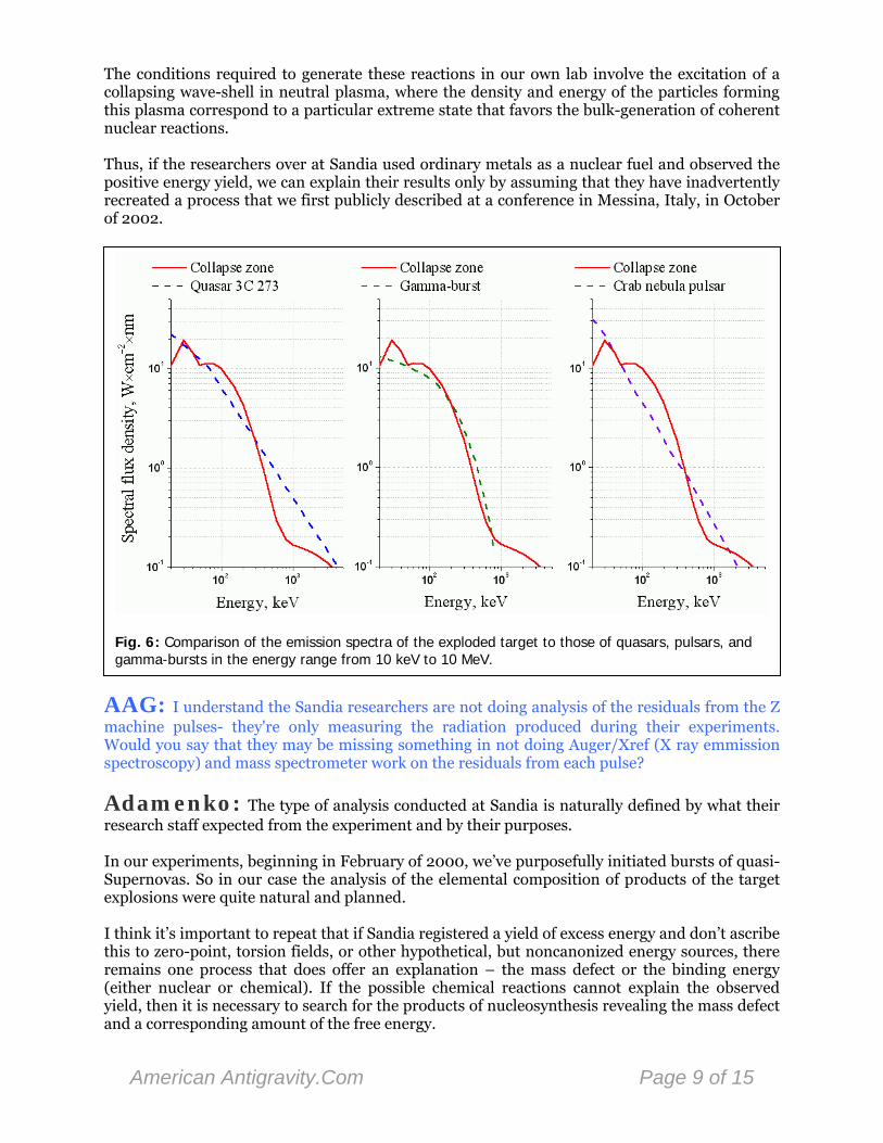
The conditions required to generate these reactions in our own lab involve the excitation of a collapsing wave-shell in neutral plasma, where the density and energy of the particles forming this plasma correspond to a particular extreme state that favors the bulk-generation of coherent nuclear reactions. Thus, if the researchers over at Sandia used ordinary metals as a nuclear fuel and observed the positive energy yield, we can explain their results only by assuming that they have inadvertently recreated a process that we first publicly described at a conference in Messina, Italy, in October of 2002.
Fig. 6: Comparison of the emission spectra of the exploded target to those of quasars, pulsars, and gamma-bursts in the energy range from 10 keV to 10 MeV.
AAG: I understand the Sandia researchers are not doing analysis of the residuals from the Z machine pulses- they're only measuring the radiation produced during their experiments. Would you say that they may be missing something in not doing Auger/Xref (X ray emmission spectroscopy) and mass spectrometer work on the residuals from each pulse?
Adamenko: The type of analysis conducted at Sandia is naturally defined by what their research staff expected from the experiment and by their purposes. In our experiments, beginning in February of 2000, we’ve purposefully initiated bursts of quasi-Supernovas. So in our case the analysis of the elemental composition of products of the target explosions were quite natural and planned. I think it’s important to repeat that if Sandia registered a yield of excess energy and don’t ascribe this to zero-point, torsion fields, or other hypothetical, but noncanonized energy sources, there remains one process that does offer an explanation – the mass defect or the binding energy (either nuclear or chemical). If the possible chemical reactions cannot explain the observed yield, then it is necessary to search for the products of nucleosynthesis revealing the mass defect and a corresponding amount of the free energy.
American Antigravity.Com Page 9 of 15

AAG: What directions would you propose going in the future? How do you break the paradigm "block" which doesn't allow people to even attempt to do analysis which may verify your results at another institution with a pulsed power device which may be obtaining the same results you have?
Explosive Inversion: Target samples are literally turned inside out from the explosion.
Adamenko: The high-energy pulse apparatus isn’t enough by itself to reproduce the experiments we’re conducting at Proton 21 – to generate the required shock compression it’s necessary to thoroughly reproduce the experimental setup described in our patent. Also, you have to carefully tune the apparatus in order to create the necessary conditions to generate the chain of self-organizing physical processes in the target and surrounding substrate. Without this you won’t get a successful response from the initiating action of a beam driver. It’s a complex process, but we’re open to participating with other organizations in an open, forthright manner in order to assist them with replicating these experiments. It’s a collaborative strategy that will save everyone a lot of time and effort, and ultimately lead to the advancement of science and humanity. This approach to open, collaborative research is by far the best way to break out of the old paradigm and usher in a new era of understanding, and it’s going to be something that we’re going to direct a great deal of effort to over the next couple of years.
AAG: Does the research that you've performed offer any hope for Low-Energy Nuclear Reaction (LENR) technologies, such as Cold-Fusion, Bubble-Fusion, or anything along those lines?
Adamenko: I think that it is the central question of this interview, and the answer is unequivocally YES!!! I believe that our theoretical studies and experimental research not only give the hope to the LENR-trend, but also significantly clarify the physical mechanisms underlying the LENR process. Thus, our work should allow researchers in the LENR field to understand the mechanism of these nuclear processes in order to optimize them for eventual use in commercial energy generation. I believe that the collective and coherent effects of nuclear interactions in dense substances like the kind we use allow us to precisely describe the mechanisms inherent in LENR reactions, and also to finally explain the great number of accidental LENR experiments, in which various products or effects of nuclear reactions were revealed in a very unexpected manner. These include neutrons, newly synthesized chemical elements, changes in the distribution of natural concentrations of stable isotopes, and the emission of light, heat, and other previously unexplained phenomenon. Some of the more traditional LENR experiments have an explicit relationship to our artificially initiated collapse. For example, let’s assume for a second that the self-collapse of an artificially formed macroscopic bubble is possible. In this experiment, we’re faced with the self-collapse of a disorganized and highly-inefficient collection of microscopic gas-bubbles where each event
American Antigravity.Com Page 10 of 15
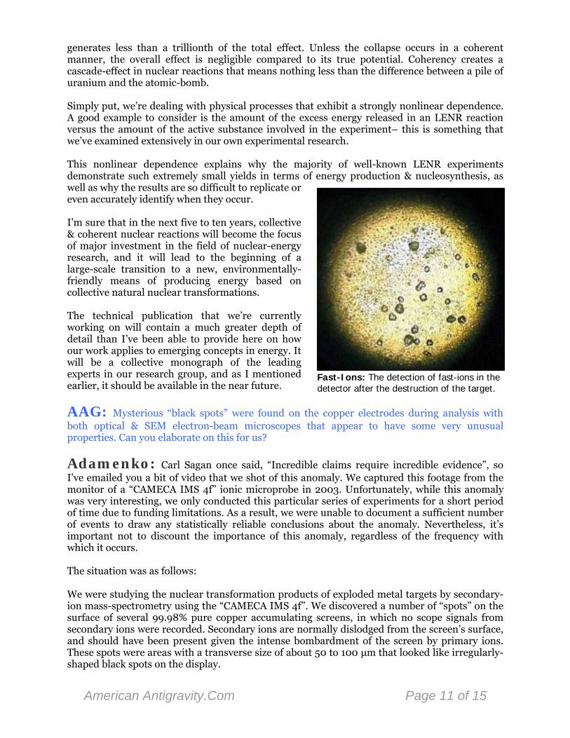
generates less than a trillionth of the total effect. Unless the collapse occurs in a coherent manner, the overall effect is negligible compared to its true potential. Coherency creates a cascade-effect in nuclear reactions that means nothing less than the difference between a pile of uranium and the atomic-bomb. Simply put, we’re dealing with physical processes that exhibit a strongly nonlinear dependence. A good example to consider is the amount of the excess energy released in an LENR reaction versus the amount of the active substance involved in the experiment– this is something that we’ve examined extensively in our own experimental research.
Fast-Ions: The detection of fast-ions in the detector after the destruction of the target.
This nonlinear dependence explains why the majority of well-known LENR experiments demonstrate such extremely small yields in terms of energy production & nucleosynthesis, as well as why the results are so difficult to replicate or even accurately identify when they occur. I’m sure that in the next five to ten years, collective & coherent nuclear reactions will become the focus of major investment in the field of nuclear-energy research, and it will lead to the beginning of a large-scale transition to a new, environmentally-friendly means of producing energy based on collective natural nuclear transformations. The technical publication that we’re currently working on will contain a much greater depth of detail than I’ve been able to provide here on how our work applies to emerging concepts in energy. It will be a collective monograph of the leading experts in our research group, and as I mentioned earlier, it should be available in the near future.
AAG: Mysterious “black spots” were found on the copper electrodes during analysis with both optical & SEM electron-beam microscopes that appear to have some very unusual properties. Can you elaborate on this for us?
Adamenko: Carl Sagan once said, “Incredible claims require incredible evidence”, so I’ve emailed you a bit of video that we shot of this anomaly. We captured this footage from the monitor of a “CAMECA IMS 4f” ionic microprobe in 2003. Unfortunately, while this anomaly was very interesting, we only conducted this particular series of experiments for a short period of time due to funding limitations. As a result, we were unable to document a sufficient number of events to draw any statistically reliable conclusions about the anomaly. Nevertheless, it’s important not to discount the importance of this anomaly, regardless of the frequency with which it occurs. The situation was as follows: We were studying the nuclear transformation products of exploded metal targets by secondary-ion mass-spectrometry using the “CAMECA IMS 4f”. We discovered a number of “spots” on the surface of several 99.98% pure copper accumulating screens, in which no scope signals from secondary ions were recorded. Secondary ions are normally dislodged from the screen’s surface, and should have been present given the intense bombardment of the screen by primary ions. These spots were areas with a transverse size of about 50 to 100 μm that looked like irregularly-shaped black spots on the display.
American Antigravity.Com Page 11 of 15

So basically, the crux of our observation was the absence of a secondary ion flux in the scope for the entire range of ion masses analyzed by the device in the area of the black spots. In following the normal procedures for interpreting the images of the ion microprobe, we can only conclude that in the case of these anomalous black spots, not only are they not composed of any of the known chemical elements, but they’re also not composed of any type of previously undiscovered heavier element – in the case of our equipment, up to 480 a.m.u. which is the boundary of the range of IMS 4f. Our operators have been making observations of this kind for decades, and this was the first time they’d encountered this type of anomaly. If it wasn’t any type of known atom, then what could it possibly be? We obsessively searched all of the specialty literature for an answer, but didn’t find any description of a similar phenomenon ever being documented before these events.
Fig. 7: The “black spot”. Secondary ion images. Investigation method is the secondary ion mass spectrometry (IMS-4f device, analyzed mass range is up to 500).
We noticed something else, also – even stranger than the lack of secondary ions. We were subjecting the black spots to a heavy ion bombardment in an attempt to pick up a secondary signal when we realized that not only were we not seeing a secondary signal, but there was also a complete absence of a signal from the primary ions in the beam of a microprobe! The ions that we bombarded the spot with simply seem to have disappeared, quite literally without a trace. At first I refused to believe that this could even be possible, because the primary ions are reflected (scattered) from any surface in such a great amount that the secondary image of these ions on the display is transformed always into a continuous glow on the scope’s viewing-screen. This omnipresent background signal is the reason that the scope’s display is automatically switched-off after a period of time – to prevent screenburn from the primary ions. As improbable as it may sound, the absence of reflected primary ions from the surface of the black spot must indicate that the primary ions arriving at the spot surface were captured by it! In another attempt to get a signal from the spot surface, the operator gradually scanned the whole dynamic range of masses of secondary ions accessible to the device. This was performed a while after the primary beam was switched-off. While slowly turning the tuning knob of the
American Antigravity.Com Page 12 of 15

device, the operator noticed a flickering spot with decreasing intensity near 433 a.m.u. This flicker was positioned inside the black spot and occupied a small part of its area, and several seconds after the beginning of the observation, the brightness of the flickering spot decreased to zero (i.e. the luminous spot against the background of the black area disappeared). We repeated this new experiment by switching the beam on again for several minutes and again switching it back off. The image of a flickering spot at a mass of 433 a.m.u. arose with the same initial brightness and again disappeared from view within several seconds. In both cases, the boundaries of the black spot were invariable. After repeating this power-cycling & observation routine 12 times, we established that the initial luminous intensity of the 433 a.m.u. spot after a pause was proportional to the duration of the pause, and the decrease in luminosity intensity as it faded from view had an exponential character.
Transmutation: An iron mass embedded in a 99.98% pure copper target sample.
During the analysis of another black spot with the use of the ionic microprobe, the operator observed a pattern similar to that described above, but different in that the luminosity arose not inside the black spot, but instead occurred in a non-uniform manner along the length of the black spot’s winding boundary. We’ve only found one suitable explanation for these unusual effects. Consider for a moment the focal region of a collapse, where the density of the substance in a collapsing shell reaches extreme values approaching those characteristic of the conditions in a collapsing star. At the moment of transition from implosion to explosion in the collapsing shell, a strongly ionized substance is ejected consisting of superheavy nuclei in which the specific binding energies per nucleon are far below their maximum values. Academician A. Migdal showed that the Coulomb barrier for such nuclei can be almost completely suppressed by a so-called “nuclear condensate” of negatively charged mesons which are formed in the nuclei in sufficient numbers to balance out the Coulomb field of nuclear protons. I believe that these nuclei can exoergically capture the nuclei of the normal atoms that surround them when those atoms reach a certain resonant temperature range. After that, the decay cycle for these new superheavy nuclei will occur using the normal induced-decay mechanisms that I’ve described previously. The multiple repetition of this “absorption-boiling-evaporation” cycle leads to a growth in both the mass of the superheavy nucleus and its specific binding energy up to maximum values exceeding 105 a.m.u. and 35 MeV against the background of the nuclear transformation of the surrounding substance in the opposite direction. The accumulation rate of products boiling off the growing superheavy nuclei will be proportional to the surface area of the superheavy substance in contact with surrounding environment, and inversely proportional to the difference in temperature of this environment from its optimum value to overcome the Coulomb barrier and hence contribute nuclei from nearby atoms to the growing nuclei.
American Antigravity.Com Page 13 of 15
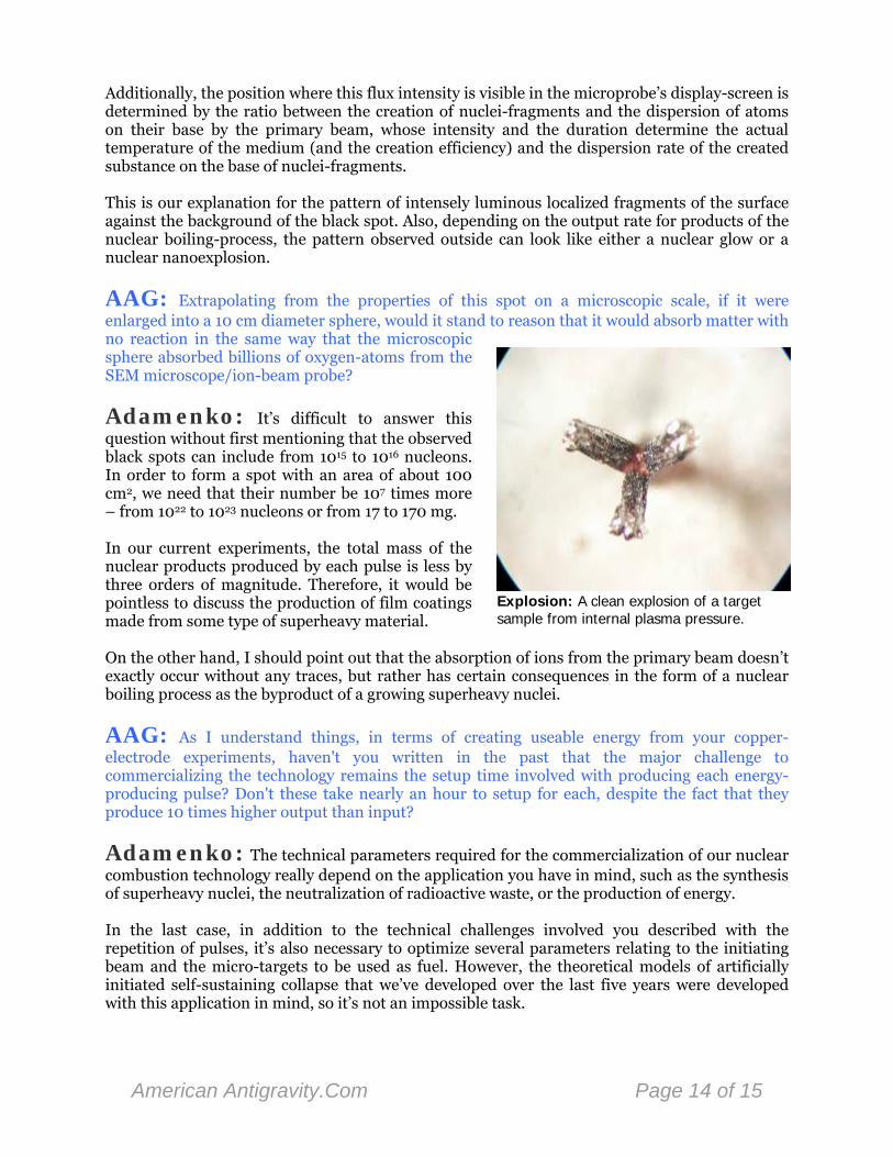
Additionally, the position where this flux intensity is visible in the microprobe’s display-screen is determined by the ratio between the creation of nuclei-fragments and the dispersion of atoms on their base by the primary beam, whose intensity and the duration determine the actual temperature of the medium (and the creation efficiency) and the dispersion rate of the created substance on the base of nuclei-fragments. This is our explanation for the pattern of intensely luminous localized fragments of the surface against the background of the black spot. Also, depending on the output rate for products of the nuclear boiling-process, the pattern observed outside can look like either a nuclear glow or a nuclear nanoexplosion.
Explosion: A clean explosion of a target sample from internal plasma pressure.
AAG: Extrapolating from the properties of this spot on a microscopic scale, if it were enlarged into a 10 cm diameter sphere, would it stand to reason that it would absorb matter with no reaction in the same way that the microscopic sphere absorbed billions of oxygen-atoms from the SEM microscope/ion-beam probe?
Adamenko: It’s difficult to answer this question without first mentioning that the observed black spots can include from 1015 to 1016 nucleons. In order to form a spot with an area of about 100 cm2, we need that their number be 107 times more – from 1022 to 1023 nucleons or from 17 to 170 mg. In our current experiments, the total mass of the nuclear products produced by each pulse is less by three orders of magnitude. Therefore, it would be pointless to discuss the production of film coatings made from some type of superheavy material. On the other hand, I should point out that the absorption of ions from the primary beam doesn’t exactly occur without any traces, but rather has certain consequences in the form of a nuclear boiling process as the byproduct of a growing superheavy nuclei.
AAG: As I understand things, in terms of creating useable energy from your copper-electrode experiments, haven't you written in the past that the major challenge to commercializing the technology remains the setup time involved with producing each energy-producing pulse? Don't these take nearly an hour to setup for each, despite the fact that they produce 10 times higher output than input?
Adamenko: The technical parameters required for the commercialization of our nuclear combustion technology really depend on the application you have in mind, such as the synthesis of superheavy nuclei, the neutralization of radioactive waste, or the production of energy. In the last case, in addition to the technical challenges involved you described with the repetition of pulses, it’s also necessary to optimize several parameters relating to the initiating beam and the micro-targets to be used as fuel. However, the theoretical models of artificially initiated self-sustaining collapse that we’ve developed over the last five years were developed with this application in mind, so it’s not an impossible task.
American Antigravity.Com Page 14 of 15
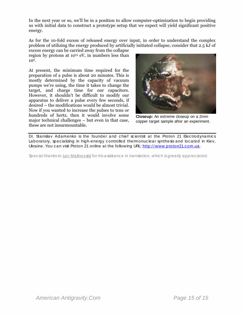
In the next year or so, we’ll be in a position to allow computer-optimization to begin providing us with initial data to construct a prototype setup that we expect will yield significant positive energy.
Closeup: An extreme closeup on a 2mm copper target sample after an experiment.
As for the 10-fold excess of released energy over input, in order to understand the complex problem of utilizing the energy produced by artificially initiated collapse, consider that 2.5 kJ of excess energy can be carried away from the collapse region by protons at 1015 eV, in numbers less than 106. At present, the minimum time required for the preparation of a pulse is about 20 minutes. This is mostly determined by the capacity of vacuum pumps we’re using, the time it takes to change the target, and charge time for our capacitors. However, it shouldn’t be difficult to modify our apparatus to deliver a pulse every few seconds, if desired – the modifications would be almost trivial. Now if you wanted to increase the pulses to tens or hundreds of hertz, then it would involve some major technical challenges – but even in that case, these are not insurmountable. Dr. Stanislav Adamenko is the founder and chief scientist at the Proton 21 Electrodynamics Laboratory, specializing in high-energy controlled thermonuclear synthesis and located in Kiev, Ukraine. You can visit Proton 21 online at the following URL: http://www.proton21.com.ua. Special thanks to Lev Malinovskij for his assistance in translation, which is greatly appreciated.
American Antigravity.Com Page 15 of 15
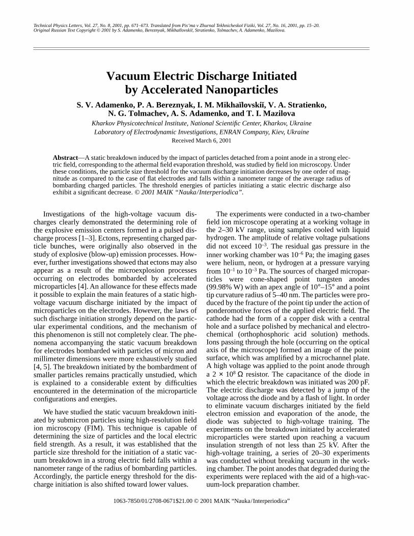
1063-7850/01/2708- $21.00 © 2001 MAIK “Nauka/Interperiodica”0671
Technical Physics Letters, Vol. 27, No. 8, 2001, pp. 671–673. Translated from Pis’ma v Zhurnal Tekhnichesko
œ
Fiziki, Vol. 27, No. 16, 2001, pp. 15–20.Original Russian Text Copyright © 2001 by S. Adamenko, Bereznyak, Mikha
œ
lovski
œ
, Stratienko, Tolmachev, A. Adamenko, Mazilova.
Investigations of the high-voltage vacuum dis-charges clearly demonstrated the determining role ofthe explosive emission centers formed in a pulsed dis-charge process [1–3]. Ectons, representing charged par-ticle bunches, were originally also observed in thestudy of explosive (blow-up) emission processes. How-ever, further investigations showed that ectons may alsoappear as a result of the microexplosion processesoccurring on electrodes bombarded by acceleratedmicroparticles [4]. An allowance for these effects madeit possible to explain the main features of a static high-voltage vacuum discharge initiated by the impact ofmicroparticles on the electrodes. However, the laws ofsuch discharge initiation strongly depend on the partic-ular experimental conditions, and the mechanism ofthis phenomenon is still not completely clear. The phe-nomena accompanying the static vacuum breakdownfor electrodes bombarded with particles of micron andmillimeter dimensions were more exhaustively studied[4, 5]. The breakdown initiated by the bombardment ofsmaller particles remains practically unstudied, whichis explained to a considerable extent by difficultiesencountered in the determination of the microparticleconfigurations and energies.
We have studied the static vacuum breakdown initi-ated by submicron particles using high-resolution fieldion microscopy (FIM). This technique is capable ofdetermining the size of particles and the local electricfield strength. As a result, it was established that theparticle size threshold for the initiation of a static vac-uum breakdown in a strong electric field falls within ananometer range of the radius of bombarding particles.Accordingly, the particle energy threshold for the dis-charge initiation is also shifted toward lower values.
The experiments were conducted in a two-chamberfield ion microscope operating at a working voltage inthe 2–30 kV range, using samples cooled with liquidhydrogen. The amplitude of relative voltage pulsationsdid not exceed 10
–3
. The residual gas pressure in theinner working chamber was 10
–6
Pa; the imaging gaseswere helium, neon, or hydrogen at a pressure varyingfrom 10
–1
to 10
–3
Pa. The sources of charged micropar-ticles were cone-shaped point tungsten anodes(99.98% W) with an apex angle of 10
°
–15
°
and a pointtip curvature radius of 5–40 nm. The particles were pro-duced by the fracture of the point tip under the action ofponderomotive forces of the applied electric field. Thecathode had the form of a copper disk with a centralhole and a surface polished by mechanical and electro-chemical (orthophosphoric acid solution) methods.Ions passing through the hole (occurring on the opticalaxis of the microscope) formed an image of the pointsurface, which was amplified by a microchannel plate.A high voltage was applied to the point anode througha 2
×
10
8
Ω
resistor. The capacitance of the diode inwhich the electric breakdown was initiated was 200 pF.The electric discharge was detected by a jump of thevoltage across the diode and by a flash of light. In orderto eliminate vacuum discharges initiated by the fieldelectron emission and evaporation of the anode, thediode was subjected to high-voltage training. Theexperiments on the breakdown initiated by acceleratedmicroparticles were started upon reaching a vacuuminsulation strength of not less than 25 kV. After thehigh-voltage training, a series of 20–30 experimentswas conducted without breaking vacuum in the work-ing chamber. The point anodes that degraded during theexperiments were replaced with the aid of a high-vac-uum-lock preparation chamber.
Vacuum Electric Discharge Initiated by Accelerated Nanoparticles
S. V. Adamenko, P. A. Bereznyak, I. M. Mikha
œ
lovski
œ
, V. A. Stratienko, N. G. Tolmachev, A. S. Adamenko, and T. I. Mazilova
Kharkov Physicotechnical Institute, National Scientific Center, Kharkov, Ukraine Laboratory of Electrodynamic Investigations, ENRAN Company, Kiev, Ukraine
Received March 6, 2001
Abstract
—A static breakdown induced by the impact of particles detached from a point anode in a strong elec-tric field, corresponding to the athermal field evaporation threshold, was studied by field ion microscopy. Underthese conditions, the particle size threshold for the vacuum discharge initiation decreases by one order of mag-nitude as compared to the case of flat electrodes and falls within a nanometer range of the average radius ofbombarding charged particles. The threshold energies of particles initiating a static electric discharge alsoexhibit a significant decrease.
© 2001 MAIK “Nauka/Interperiodica”.
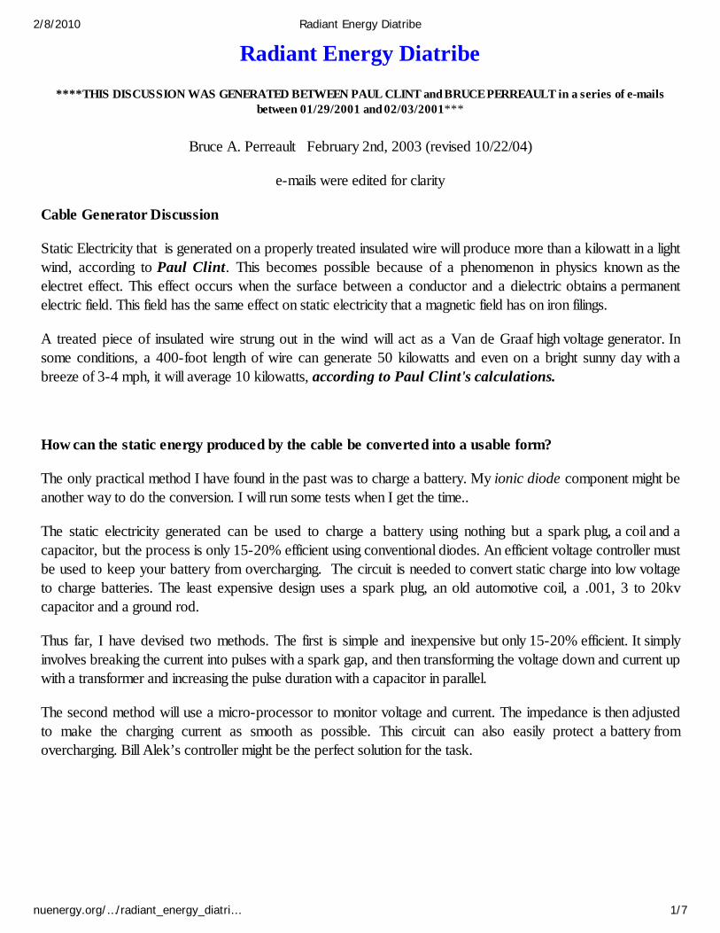
Radiant Energy Diatribe
****THIS DISCUSSION WAS GENERATED BETWEEN PAUL CLINT and BRUCE PERREAULT in a series of e-mailsbetween 01/29/2001 and 02/03/2001***
Bruce A. Perreault February 2nd, 2003 (revised 10/22/04)
e-mails were edited for clarity
Cable Generator Discussion
Static Electricity that is generated on a properly treated insulated wire will produce more than a kilowatt in a lightwind, according to Paul Clint. This becomes possible because of a phenomenon in physics known as theelectret effect. This effect occurs when the surface between a conductor and a dielectric obtains a permanentelectric field. This field has the same effect on static electricity that a magnetic field has on iron filings.
A treated piece of insulated wire strung out in the wind will act as a Van de Graaf high voltage generator. Insome conditions, a 400-foot length of wire can generate 50 kilowatts and even on a bright sunny day with abreeze of 3-4 mph, it will average 10 kilowatts, according to Paul Clint's calculations.
How can the static energy produced by the cable be converted into a usable form?
The only practical method I have found in the past was to charge a battery. My ionic diode component might beanother way to do the conversion. I will run some tests when I get the time..
The static electricity generated can be used to charge a battery using nothing but a spark plug, a coil and acapacitor, but the process is only 15-20% efficient using conventional diodes. An efficient voltage controller mustbe used to keep your battery from overcharging. The circuit is needed to convert static charge into low voltageto charge batteries. The least expensive design uses a spark plug, an old automotive coil, a .001, 3 to 20kvcapacitor and a ground rod.
Thus far, I have devised two methods. The first is simple and inexpensive but only 15-20% efficient. It simplyinvolves breaking the current into pulses with a spark gap, and then transforming the voltage down and current upwith a transformer and increasing the pulse duration with a capacitor in parallel.
The second method will use a micro-processor to monitor voltage and current. The impedance is then adjustedto make the charging current as smooth as possible. This circuit can also easily protect a battery fromovercharging. Bill Alek’s controller might be the perfect solution for the task.
2/8/2010 Radiant Energy Diatribe
nuenergy.org/…/radiant_energy_diatri… 1/7
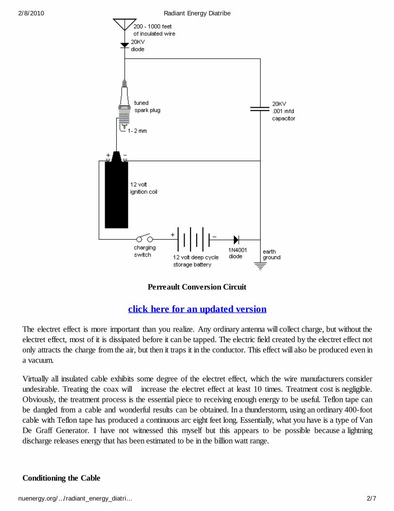
Perreault Conversion Circuit
click here for an updated version
The electret effect is more important than you realize. Any ordinary antenna will collect charge, but without theelectret effect, most of it is dissipated before it can be tapped. The electric field created by the electret effect notonly attracts the charge from the air, but then it traps it in the conductor. This effect will also be produced even ina vacuum.
Virtually all insulated cable exhibits some degree of the electret effect, which the wire manufacturers considerundesirable. Treating the coax will increase the electret effect at least 10 times. Treatment cost is negligible.Obviously, the treatment process is the essential piece to receiving enough energy to be useful. Teflon tape canbe dangled from a cable and wonderful results can be obtained. In a thunderstorm, using an ordinary 400-footcable with Teflon tape has produced a continuous arc eight feet long. Essentially, what you have is a type of VanDe Graff Generator. I have not witnessed this myself but this appears to be possible because a lightningdischarge releases energy that has been estimated to be in the billion watt range.
Conditioning the Cable
2/8/2010 Radiant Energy Diatribe
nuenergy.org/…/radiant_energy_diatri… 2/7
Buy cheap coax RF cable, that has a center wire and a shield cylindrical wire. Then cut off the outer plastic skinand put the whole cable into your oven and heat it up to about 100 degrees Celsius or more, so that the internalplastic insulation almost begins to melt.
Then apply from a D.C. high voltage source around 30 kilovolts or maybe a little less, so that there will be noarc-over yet inside the cable. Then let the cable cool down slowly again, but still apply the high voltage D.C.
When the cable has come down to room temperature again, it will be a pretty good electret!
Now hang this cable in the air and the outer layer of the shield metal (which does not have any plastic isolationskin anymore), will now attract lots of free ionized electrons from the air and charge up the outer shield metal ofthe cable. This way you can collect lots of more charges as before and have a much higher electrical output fromthis cable.
Hope this helps Regards, Stefan
The electret effect is a problem in the manufacturing of coaxial cable. This problem arises from the process usedto make insulated wire; an unwanted electret effect is created. Engineers work very hard to reduce the effect butare unable to completely eliminate it. What I am saying is that all insulated wire exhibits some electret effect. Theengineers go to great lengths to minimize it. The treatment as suggested by Stefan Hartmann should increase theelectret effect of the cable at least 100 times, and with some cable, as much as 1000 times (depending on howhard the engineers worked). The electret effect is present wherever plastic is in contact with a conductor. It ismuch better to use unshielded cable and it is cheaper as well. If you do use shielded cable, it might not draw asmuch radiant energy. To begin your radiant energy experiments string out a 300-foot length of ordinary coaxcable and do not connect the other end to anything. Use the conversion circuit in this article to convert yourcollected charge into electrical power. When you ground this circuit do not use the one that is connected to theelectric companies meter. If you do not get at least a couple of pops per minute from your spark plug you willneed to condition your cable as explained by Stefan Hartmann. Tying a bunch of 2-foot pieces of Teflon tape toyour cable will also increase its draw power.
Virtually any insulated wire has a small electric field surrounding it that attracts positively charged air molecules(called ions) to itself. This charged moving air mass induces a negative charge of static electricity that builds up inthe cable conductor. Under most circumstances, the conductor in a cable is connected to a circuit and the currentis absorbed without notice. Nevertheless, if the conductor is connected to a spark plug (whose threads aregrounded) it will produce an electric arc across the spark gap each time the voltage in the cable rises to the limitof the spark plug's gap. In some cases with a long piece of cable and some air current (wind), the spark gap willarc almost continuously. During a thunderstorm, Paul Clint reported to me that he once witnessed an eight feetlong arc during a thunderstorm. A continuous arc or one that is eight feet long indicates to me that a substantialamount of power was being received. This means that a treated piece of insulated wire can be strung out on afence and used to generate enough power to provide a home owner with all they need. It also means that it ispossible to generate power in winds that have previously been considered worthless (3-4 mph).
2/8/2010 Radiant Energy Diatribe
nuenergy.org/…/radiant_energy_diatri… 3/7
How can a small cable extract so much energy from little or no air currents?
This is easily explained. The energy collected from the cable is not derived from charge collection as one mightfirst think. It is derived from induction, as the positive ions in the air rush towards the cable. As you may or maynot be aware, the earth's atmosphere is a gigantic capacitor. At its upper level, air molecules are constantly beingionized and then as the air circulates, the charge is eventually carried to the ground that has a negative charge withrespect to the upper atmosphere.
Ham radio operators will certainly confirm that a coaxial cable strung out, as an antenna, will become highlycharged, especially in wet, stormy weather. The accumulation of charged ions is not possible in a humidenvironment. Therefore, the power is derived through charge induction rather than from static charge. This isclearly demonstrated from the fact that the power generated is directly proportional to the speed of the windrather than the square of the speed.
Still, the wire hardly intersects any of the wind. How can a little wire collect so much?
The cross section of the wind from which power is collected is much larger than you might think. Remember thatthe electret effect creates an electric field, which attracts charged air molecules as a magnet attracts iron. Thecross section of this field can be as great as 2 feet, so a 100-foot cable can intersect as much wind as a 16-footdiameter airfoil.
Have you measured the cable power output?
Measurement of the output of the cable is not a simple process. The output varies over several orders ofmagnitude for voltage, current, frequency, and is well beyond the capability of simple measuring devices.Because of this fact, I have devised a couple of indirect methods to measure output. In the first of these, I haveconnected a spark plug between a cable and ground so that whenever the voltage builds up to the arc-overvalue, a pulse of current is generated that can be counted. This method can be termed no more than a roughestimate because the shape and duration of the pulse still varies over a substantial range. Analysis of the pulseswill eventually allow us to use an average and thus devise a formula that will give a close approximation of thepower output.
The second method is simple and if done properly, very accurate. We simply place a resistive heating elementbetween the generator and ground and then into a bucket of water. The output is then measured by the change intemperature of the water. Neither of the two methods takes into account the losses of the charging circuit,battery, or inverter, etc...
Does the electret effect wear out or dissipate over time?
The question as to whether the electret effect wears out is not a simple one to answer. It is clearly being used in away that is unique. The fact of the matter is that, in general, the electret effect is unwanted, and engineers arenormally working to prevent or eliminate it. The fact that they have to work very hard to do so is an indication
2/8/2010 Radiant Energy Diatribe
nuenergy.org/…/radiant_energy_diatri… 4/7
that it is stable. Thus, the best answer I can give is that it does not wear out in the short term (years).
How can I determine if the cable will produce more power for its cost than I would have to pay theutility company?
Again, this can only be done over a long time-period because it is dependant on wind, location, humidity andpossibly other lesser, undetermined factors.
How does humidity affect cable operation?
Ham radio operators have reported that static charge builds up on their antennas more often and more intenselyin times of high humidity, rain, or snow. The technical literature reports that most atmospheric charge is carried byaerosol particles of dust or water that collect hundreds, thousands, and sometimes tens of thousands of units ofcharge. As they collect more and more charge, these particles migrate toward the earth's surface and constitute amajor component of the fair weather current.
Have you tested cable generator in other configurations such as a spiral, coil, grid, or vertical mode?
Optimum results are obtained by suspended an insulated cable between 5 to 15 feet above the ground in ahorizontal straight line. Any deviation from this will reduce the output of the cable generator.
You must use an insulated cable that is strung out horizontally. For it to function properly there should be a swagto it.
Please see... http://www.nuenergy.org/alt/transducer.htm
If you see that the cable is physically vibrating you will know that it is set up properly. Any wire will vibrate but itneeds to be electrically insulated and possess the electret effect to generate self charge. There is more than justwind that is involved. The cable will vibrate sometimes with only the slightest breeze. As you can see here thereis a real energy source that is waiting to be harnessed. Essentially, we are utilizing the induction from a moving ionfield. This is why a cable can be seen to physically vibrate. Where the seat of kinetic activity actually originatesfrom I do not know. What I do know for certain is that energy is present in the system.
Will a bare wire generate a charge?
Bare wire will not generate a charge. The electret effect has to be present.
Please see... http://www.esdjournal.com/static/shower/shower.html
2/8/2010 Radiant Energy Diatribe
nuenergy.org/…/radiant_energy_diatri… 5/7
Has anyone measured the ion density of the atmosphere?
Yes, the average is 3000 ions per cubic meter. The figure is subject to stupendous variations of many orders ofmagnitude as shown by this quote from "Atmospheric Electricity in the Planetary Boundary Layer" by William A.Hoppel, R.V. Anderson and John C. Willet. "Most atmospheric processes are interrelated and cannot be studiedin isolation, but it is possible to identify one or two dominant influences. In the case of Atmospheric electricity inthe Planetary Boundary Layer, however, separating the various causes and their effects can be extremely difficult.In fact, this field may be unique with respect to its sensitivity to many disparate phenomena spanning atremendous range of scales in both space and time. For example, locally produced turbulent fluctuations inspace-charge density have an effect roughly comparable in magnitude to that of changes in the globalthunderstorm activity on electric-field variations within the Planetary Boundary Layer."
The ion density does not appear to provide enough charge to account for the current generated by thecable. Are there other sources of energy contributing to the current?
Both the electric field of the earth (typically 100-200 volts) and that of the cable produce an effect called theinduction charging mechanism. This is a physical process for particle charging involving the collision of pairs ofparticles in an ambient electric field. Electric charge induced on particles surface by the ambient electric field ismade available for transfer when the two particles come into contact. A subsequent differential particle motionthat is influenced by gravity is postulated to result in large scale charge separation. The specific role of inductioncharging in the electrification of thunderclouds has not been resolved.
Another effect that is unquestionably effecting the cable is the double layer effect. On the surface of a substance alayer of electric dipoles whose axes have an average orientation normal to the surface, double layers may appearon the interface of a solid and gas, liquid and gas, liquid and liquid, etc. They arise whenever media with differentelectron affinities (forces of attraction, or work function) are contiguous, and if dipoles are available. A netpotential difference, the electrokinetic potential exists across the double layer. This effect is demonstrated in thesuper capacitor. Therefore, our cable acts like a super capacitor of high farads.
Yet, another source of atmospheric charge collected by the cable is due to aerosol charges. These particles ofdust or water form dipoles and disproportionally collect one charge or the other. Where ions carry only single ordouble units of charge, aerosols carry hundreds, to tens of thousands, of units of charge. The fact humidity is suchan important factor in the output of the cable indicates that aerosols are an important source of the energy itcollects.
What else would be needed besides a cable to provide a good alternate electrical source for a home?
You would need a battery or bank of batteries, a charge controller, and a grid tied inverter.
* Note: Paul Clint forwarded e-mails between him and Bruce Perreault to Jerry Decker who posted theirdiscussion on Keelynet http://www.keelynet.com/electret.htm All e-mails between Paul Clint and Bruce Perreault
are archived on hard-drive.
2/8/2010 Radiant Energy Diatribe
nuenergy.org/…/radiant_energy_diatri… 6/7
rexresearch.com Home
Robert Adams: Motor-Generator
Eastern Bay News (1-18-2001) Applied Modern 20th Century Aether Science (Excerpts) UK Patent # 2,282,708 (Adams & Aspden) Nexus Magazine (August-September 1993) Nexus Magazine (December-January 1993) Nexus Magazine (June-July 1995) The Golden Ratio Motor Generator Adams Special Release of Information... Miscellaneous Notes by Dr Adams Tim Harwood's Replication Keelynet BBS Discussions New Energy News (December 1996): H. Aspden Alternative Energy Institute (July 17, 2002): Adams vs. Lutec Biodata of Robert Adams
Links: Robert Adams' Website: http://www.aethmogen.com Kits: http://www.butlerlabs.com/es.htm Discussion Group: http://groups.yahoo.com/group/free_energy/
Eastern Bay News (1-18-2001)
Aether Energy an Alternative - Claim
A Whakatane-based scientist believes he is helping to create one of the greatest breakthroughs inhuman history. Denise Landau talks alternative clean energy production with one of the world'sleading energy scientists.
After a lifetime devoted to researching alternative clean energy production Dr Robert Adams isabout to publish his latest work which shows that aether, the building block of the physical universe,can be freely harnessed to produce clean, pollution-free energy.
2/8/2010 Robert Adams & Harold Aspden --- Mo…
I:/Data_PC_CHR/…/adamotor.htm 1/77

Now aged 80, Dr Adams and his colleagues new work delivers mankind on to the doorstep of anunimaginably exciting and awe-inspiring future.
Take any image of science fiction and open your mind because that's the direction this new world ofaether energy is offering, says Dr Adams.
He is internationally recognised as one of the world's five leading scientists in the field of researchinto the new clean energy technologies.
Aether scientists believe their discoveries effectively eliminate the theories of relativity and traditionalviews of physics and cosmology.
An international network of maverick "behind the scenes" scientists, such as Whakatane's Adams, ison the brink of publicly challenging the traditional Western scientific establishment.
They sincerely believe that the Earth's and the human race's very survival depends upon it.
Dr Adams says many ancient cultures were aware of the power of aether energy and used it fortheir people's and the environment's betterment.
So what is the aether and how can it be applied to our lives today?
Scientists describe aether as a superfluidic particulate medium which pervades all space - it is thebuilding block of the physical universe. The medium, in one of its forms, is responsible for gravityand inertia.
They even go so far to say it is a medium controllable by mind and can be manipulated by thought.
Does a memory from the movie, Star Wars, and its mystical element illustrated by the Force ringany bells here?
Scientifically, these "outside the square" thinking individuals call themselves new energy scientistsand Dr Adams latest book is entitled Special Update 2000 edition of Applied Modern 20thCentury Aether Science.
"This new energy technology is going to change the world we live in on an immense scale."
Dr Adams formally lays claim to discovering a new law of Nature, which he designates 'the AdamsLaw'.
"I have proved over hundreds of thousands of hours of hard labour at laboratory benches andmachine shops, that these aethric energies are manifesting at unity/zero point, whereby the bottomline is that there is no longer any reference point from which to base any kind of so-called'efficiency' test."
Dr Adams' latest invention does read like something taken straight out of a Star Trek episode - theAdams triplex aethric energy motor generator.
This device is a super power, thermo, impulse, salient pole, open magnetic circuit, repulsion, self-
2/8/2010 Robert Adams & Harold Aspden --- Mo…
I:/Data_PC_CHR/…/adamotor.htm 2/77
starting, reluctance electric motor generator.
The motor generator is so named because of it's unorthodox and unusual ability to manifestconsiderable aetheric energy from three different areas of the machine.
He says the revolutionary machine, the first of its kind in the world, provides economical, clean, safepower.
What it means, says Dr Adams, is every fossil-fuelled and nuclear power station in the world couldbe shut down in the space of three years.
Dr Adams talks about expanded inductive energy and energy harnessed at the air gap between hismachine's rotors and stators. These two elements combined provides the driving power of themotor.
"The important roles played by these two sources of force have never before been properlyhighlighted.
"They have eluded mainstream academia and scientists for over a century in regard to their vitalimportance in machine design, and this explains why electric motors have never beer improvedupon during these past 100 or so years."
He adds that it is incredible to realise that electrical engineers and scientists in this modern age oftechnology are still taught to use free trapped electromagnetic energy to destroy the source of thesaid energy, by placing these 'stone age' motors across the national grid systems and/or batteryenergy sources.
"In this brutal way, millions of megawatts of energy is wasted daily throughout the world and there isno excuse for allowing such a monstrous waste to persist any longer."
His supporting written documentation includes papers written by eminent scientific pioneers inferromagnetics and aether technology, including the United Kingdom's pioneering engineer DrHarold Aspden.
Dr Adams says his book contains the revelation of the century and is packed with undeniableevidence of the presence of the aether and it's awesome powers.
This exploration into the vast frontier of aether energy science technologies also outlines part of hisown journey through the corridors of a fascinating and challenging world of new, clean, safe andinexhaustible source of energy, he says.
Dr Adams shares his own vital discoveries and experiences from a lifetime of critical analyses on thesubject in conjunction with his collaborating colleagues world-wide.
He includes scientific papers written by scientists of eminence and international repute as pioneers inthe fields of ferromagnetics and aether technology.
Dr Adams also deals with his own sceptics - with reverence and caustic soda alike - and includes
2/8/2010 Robert Adams & Harold Aspden --- Mo…
I:/Data_PC_CHR/…/adamotor.htm 3/77
some of their narratives.
The book is a biography and a significant contribution to the history of modern day true science, arecord if discovery and innovation which is fertile and absorbing, he believes.
"In writing this special update I am donating into the public domain further valuable information.
"This is particularly for the benefit of those interested in the new, clean free energy sciences with theview to fostering encouragement for these people, to join in the rank of their pioneers bycollaborating and sharing information on an international basis."
Four years ago, former New Zealand Minister of Energy, Doug Kidd, publicly stated his belief inthe concept of "over unity" machines operating in laboratories overseas at an address to the annualgeneral meeting of The Energy Efficiency and Conservation Authority.
Mr Kidd referred to the almost science-fiction field of over-unity where new machines recordedoutput power at 28 times greater than input power from the likes of the Patterson power cell andwhere power continues to be produced long after the input source is turned off.
"I'm not talking about nuclear power," Mr Kidd explained. But the restrained anarchist lurking deepinside me is tickled by the thought that your line monopoly ... could become worthless junk, aswould the dinosaur at Huntly and the large hunks of concrete we call hydro stations would becomemarginal stations.
"According to accepted notions of physics, it is not possible. But once upon a time it was acceptedwisdom that the sun revolved around the Earth. Your life depended on believing it!"
Excerpts from:
Applied Modern 20th Century Aether Science [Out of Print]
Table of Contents
Acknowledgements Preface Acknowledgement of Commendation Introduction by Author's Wife Tapping Nature's Clean Inexhaustible Energy With the Adams Technologies Letter to a New Zealand MP, the Hon Peter Hodgson (Energy Minister) Politics and New Energy. (Excerpts from previous Energy Minister's (Hon DougKidd's) Address 1996) Personal Reply from the Hon. Doug Kidd to the Author Thermodynamics and Free Energy by Dr. Peter A. Lindemann Thermo Motor Generator (publication in NZ Electrical Focus, 1997) A Sceptic Writes Adams Writes Cynicism
2/8/2010 Robert Adams & Harold Aspden --- Mo…
I:/Data_PC_CHR/…/adamotor.htm 4/77
Correspondence From Another Sceptic (Graham Keith) Adams' Reply to Keith Usages of Physics and the Inventor's Health, by Paulo N Correa The End of Fossil Fuels by The Arlington Instutute, USA Excerpts from the Author's Publication Aug/Sept 1993 (Nexus InternationalMagazine) Introduction into Applied Aether Energy Science On the Phenomena of Wattless (Currentless) Power Aether Energy Electrical Energy Generation and the Vital Role Played by Temperature and TimeFactors... Translocating Potential Gradient to the Motor Unity, Zero Point, Over Unity, Over 100% and Various Other Definitions... Aetheric Electrical Technological Science and the Adams Connection The Adams Thermo Motor Generator (1) Diagrams of Mosfet Calorimeter and Water Heat Power Ohms Law Input Power Measurement and its Significance in the Adams Technologies The Dispatch of Ohms Law in the New Dimension of Clean Energy Technologies Tesla, Adams, Ohms Law and The Aether Adams' Technology Proves Tesla's Discoveries... Diagram of Mosfet and Load Resistant Calorimeters Diagram of Calorimeter Test Power From Room Heat by Dr. Harold Aspden The Adams Thermo Motor Generator (2) The Adams Triplex Aetheric Energy Motor Generator Correspondence to & from Radio WBAI Pacifica, NY - Kaku, Williams, Adams,Lindemann "Have We Discovered the Neno?" by Dr. Harold Aspden The Adams - Aspden Motor Patent The Impending Energy Crisis by Dr. Harold Aspden The Secret of the Adams Moter by Dr. Harold Aspden "Do We Really Understand Magnetism?" by Dr. Harold Aspden Switched Reluctance Motors by Dr. Harold Aspden Reluctance Motor Has 100% Plus Efficiency, Electrical Review, U.K. 1993 Adams Motor Analysis Report and Graphs, L. Low, USA Free Energy, Gravity and The Aether by Dan A. Davidson (Excerpts) What is ........ Aether? (Excerpts) The Light Centre (David Saltrese, Wales) Machine Test Run Analyses (Examples) More Correspondence from Dr. Lindemann Revelation of the Myths of 'Unity' and Beyond On The Matter of Excess Heat Manifestation The Energy Metamorphisis Excerpt from 'The Harmonic Conquest of Space' by Capt. Bruce Cathie Prologue to 'The Transistor Enigma'
2/8/2010 Robert Adams & Harold Aspden --- Mo…
I:/Data_PC_CHR/…/adamotor.htm 5/77
Introduction to 'The Transistor Enigma' Who Invented the Transistor and When Was it Originally Invented? The Truth Must Prevail A Summary - Shulman's Roswell Expectations and the Bell Boys Appendix to 'The Transistor Enigma' Champion of Aether Energy by Lenora Anderson
Tapping Nature's Clean Inexhaustible Energy With The Adams Technologies
Imagine your own plant at home, business, factory, milking shed, etc., to name but a few of thescores of sites and applications for such a device. Sounds like a dream?
No, it is no dream. Development of such a technology has been on-going right here in NewZealand in the Bay of Plenty for some years now by an internationally recognized scientist by thename of Dr. Robert Adams of Aethmogen Technologies.
Unprecedented progress is underway worldwide on new energy devices. Such devices will one dayin the near future pave the way to the time when we will see an end to pollution. Such devices willplay an enormous role in the doing away with the monstrosities we call power stations whichpresently interfere with our waterways and, especially in the case of the coal and oil fired stationspolluting the air we breathe. Hydro stations with their pylons and substations straddling thecountryside will meet a similar fate. The time will come when grid systems will not be sustainableeven to the most affluent of nations and the world will have to turn to simpler and more cost effictivealternatives. Power stations, just as the computer industry has done, will downsize quitedramatically and continue to do so rapidly until establishments such as hospitals, universities,factories, etc., will no longer be their guests. Eventually the smaller new energy devices willaccommodate these guests and they will become self-sustaining as will individual residents who willbe able to own and operate their own power supply at a "one-off" cost and store these individualunits quite comfortably in their basements or garages.
Dr. Adams has authored a new book on his own technologies titled "Special Update 2001 Editionof Applied Modern 20th Century Aether Science". This book covers the subjects of nature andpollution, politics, the environment, hte scientific establishment with its false teachings, aether energytechnologies ond devices, modern calorimetric aether power measurement techniques, thermo-moter-generators, aetheric energy from mosfets and magnets, conventional electric motors andgenerators, etc.
Dr. Adams has, for over fifty years, had serious concerns over environmental pollution, havinghimself been involved at the coal face with power plants in New Zealand in his younger years. Thisconcern has underwritten a virtual lifetime of work researching alternative energy. His concerns forhis own country go deep - he states:
"New Zealand has, over many decades now, persistently exhibited a complex of lethargy towardsits inventors and innovators in general - the sad and inevitable outcome if this attitude, as seen ioverrecent television programmes, has seen hoardes of the creme de la creme desert these shores
2/8/2010 Robert Adams & Harold Aspden --- Mo…
I:/Data_PC_CHR/…/adamotor.htm 6/77
carrying with them their innovations to a much greater recognition and prosperity overseas. Thereare various reasons which contribute to nil growth in any particular regoin in the world, but the mostlamentable is when a country or region ignores its own potential. Only of late, (perhaps as late asthe last few years - and this probably because of media scrutiny and attention) has this shamefultrend begun its reversal in New Zealand. I say "begun" because it is barely noticeable. Let NewZealand only hope it has not regressed too far before it can catch up with its overseas cousins is thisregard. In my own situation, well in excess of a ball-park 95% of the recognition I have enjoyedfrom my work has come from international quarters, that being from the United Kingdom, USA,Hong Kong, Japan, Sri Lanka, Australia, Canada, Russio, Sweden and Austra and I have not tothis day placed myself on the internet - yet!"1
The universal pace for economical and, more important, clean, pollution free energy has seen thepassing of laws in California USA requiring that ten percent of all cars sold, starting in the year2003, be zero emission vehicles. Other American States have followed suit, creating a potentialmarket for fuel free automation. The race has well and truly begun in the new energy arena with theburgeoning European and Asian laboratories following the lead and turning their attentions from thepurification of fossil fuels to the interrogation of alternative energy sources.
The electrical machine technology, developed in New Zealand by Dr. Adams of AethmogenTechnologies, in its various invented forms, is ideally suited to application in rural areas where thereare expensive line charges for power supply, or no power access at all, as in remote locations.
The system can also be adapted to the provision of steam power with which to run turbines, steamcentral heating systems in homes, business complexes, industrial plants, hospitals, hotels, airports,etc.
The system is adaptable to all motive power requirements, i.e., from marine applications right onthrough to agricultural, horticultural, fisheries, forestry, major earthworks, aeronautical andaerospace projects. Its applications are widespread, land, sea and air.
For Greater Marine Safety ~
A boon to all boat owners and operators, whether their craft be dinghys, launches, yachts, tri-marans, luxury or ocean liner vessels, clean safe energy supply is now available for motive power,power for heating water, with additional supply for cooking, lighting and general heating purposeson board. The dangers and risks associated with using on board fuel and gas can now be totallyeliminated. This clean power of the future is safe (no risk) and does not subject the environment toany interference whatsoever. It also has the unprecendented advantage of an as yet unprocuredeconomical dominance over all other power alternatives.
Quotation - from Dr. Harold Aspden PhD, BSc, FIEE, FIMech E, MInst P, C. Eng, C.Phys.Department of Electrical Engineering, University of Southampton, England:
"...there seems no reason why the Adams motor cannot be developed rapidly for general use."(1994 - 1996).
Since Dr. Aspden undertook his evaluation of the Adams technology and came to the above
2/8/2010 Robert Adams & Harold Aspden --- Mo…
I:/Data_PC_CHR/…/adamotor.htm 7/77

conclusion, the development of three different machine types have been completed and are nowready for aesthetic design formats to be considered with consequent construction for productionpurposes to follow.
Introduction into Applied Aether Energy Science
With the advent of harnessing aetheric energy with the applied Adams Technologies, it poses adifficult task to know the best possible starting point with which to describe this almost as yetvirtually unknown technology in the mainstream of electrical sciences.
The decision I have taken is to commence at the grass roots, so to speak.
It all started during 1969 when I first determined to use permanent magnets to construct an electricmotor generator that would defy Lenz's law and, in so doing, invent an electrical machine that wouldrun at unity and, so too, in turn, defy certain other orthodox laws.
Before going on further, I feel you should all be aware of the reason why I decided to turn myattentions to developing a device which would display characteristics that would serve to exhibitthat there were better ways of acheiving access to power or energy without recourse to man-madelaws. I had long ago decided that ultimately all man-made laws required re-examination at one timeor another and could never remain static in time - as time itself has constantly proved. Man-madelaws, in particular those of physics and the allied sciences, have no path to follow, in that they tendto remain finite and exhibit the distinct inability to contain the characteristic of flexibility, which theymust contain if they are to grow and expand at all, let alone grow and expand at the same pace ofthe human mind. Had the human mind taken upon itself the identity and stoliditude of these man-made Laws, the human condition would be a sad and sorry one today. Long enough had mansubjected himself to the time-weary stagnant laws of physics and the electrical sciences and itseemed to me that in order for real progress to be made in this field, someone had to be brazenenough to stomach the inevitable sticks and stones and forge onwards to a totally new mentation. Ihad followed, throughout my many years of experience and constant studies, the works of otherpioneers in other countries who had been theorising (more than experimenting in a practical sense)new ideas and hypotheses and it occured to me over and again that these scientists and inventorswere trying to equate these new ideas with endless reams of unsuccessful calculations and equationsbased on the sacrosanct (and aging) man-made electrical and associated laws. I made up my mindthat this was going to change, and change dramatically, if I was going to have anything to do with it.Many of these new pioneers, I felt, were (and are, even to this very day) trying to put new ideas upagainst old (and unfortunately still reigning) regimes and methods, which came into vogue longbefore the days of the great Leonardo da Vinci.
And so I started quietly to work according to the Laws of the Universe and Nature and along theway over the years I made some rather astonishing discoveries of my own which, at times, bowledme quite over, and still do. As time went on, empirical findings made me bold enough to come outof my shell and go public with my results of experimentation and discoveries - quietly at first. Thiswas both good and bad for me and I was eventually forced to anticipate and indeed prepare myselffor the onslaught to come. Come it did - of course!
2/8/2010 Robert Adams & Harold Aspden --- Mo…
I:/Data_PC_CHR/…/adamotor.htm 8/77
What I was doing was an affront to every respectable teaching institution on the surface of theplanet. Scores of electrical engineers and physicists bombarded me ad nauseum with the dogma, forinstance, that, with my devices, I would get absolutely nowhere without closing the loop. At lecturesthis was one of the greater thorns in the sides of my contemporaries. Very few indeed were thoseattendees who gave this matter any in-depth thought at all, and those who did (brush away thecobwebs), as I lectured on, slowly nodded, quietly smiled and shouted no more (in the way peopledo when suddenly visited by an affliction of the dropped penny syndrome) ; they just listened withgreater intensity and keen interest until the end of the lecture, when stunned murmering grew rapidlyto an ever increasing buzz of heated dissertation and debate which, incidentally, rang through thelecture chambers long after I had departed. Such lectures, especially those (most) which wereaccompanied by at least an hour and more of question and answer sessions between the attendeesand myself, were always a great joy for myself and I can say, with more than a little satisfaction,never boring for the attendees.
So it is for all my readers today to understand that, although the walk has been long, thorny andarduous at times, the journey has been one of the utmost intrigue, fulfillment and discovery wherein Ihave experienced many surprises myself. Red rags have turned to green lights, frustration to rewardand, in the end, all quite good fun.
I describe matters now pertaining to calorimeters because, as we progress, it is found that they arevital instruments for this technology - so much so that I purport them to be the only accurate meansof measuring power generated/harnessed within these devices of the Adams technologies. This fact,came to be because of the great difficulty in having to engage in applying empirical knowledge toworking with this technology, as orthodox theories/methods are of no value whatsoever in thedesign and construction or testing of these super machines.
Late 1995 - 1996 heralded in the successful and sophisticated "Adams Thermo-Motor Generator"entering the kilowatt range at greater power and performance. In addition during that period manyvarious types of calorimeters were also designed and built by myself. Experience, intuition andempirical knowledge has since led to new discoveries and more sophisticated and accuratecalorimeters.
One special unit I will mention, but briefly, as it is on the classified file, is the EquilibriumCalorimeter. Now if equal masses of copper and water are heated, for instance, over flame, forequal periods of time, the temperature of the copper rises ten times as fast as the temperature of thewater, and to cause the same temperature change of the water, it would have to be heated ten timesas long. This massive variance, in addition to other factors to be accounted for, results in thenecessity of tedious calculations which all have their resultant and inevitable error factors.
These complex ramifications of coefficients, specific heat, thermal conductivity, convection,radiation, absorption, insulation losses, have, ad infinitum, in their path of time immemorial, createdongoing contention to this day.
To put the matter to rest for my own sake, I turned to inventing a water calorimeter that woulddispense with 'calculations' and need only to rely on 'measurements'. (Measurements can be reliedupon; calculations, in calorimetry involving water, can not!). This is, then, the EquilibriumCalorimeter mentioned above.
2/8/2010 Robert Adams & Harold Aspden --- Mo…
I:/Data_PC_CHR/…/adamotor.htm 9/77

In this type of water calorimeter, a small quantity of water and a short operation time is ofparamount importance. The unit itself is unique in that its load heating element heats both the waterand copper vessel simultaneously and as the machine being tested operates in the kilowatt range, astate of equilibrium in the calorimeter is very rapidly reached after switch on of the machine, andremains so to boiling point or any desired temperature. The copper vessel containes only 0.5 litre ofwater with a boiling point time of 2.0 minutes. The fact that all componentry and water reachesequilibrium so rapidly, ensures that the resultant accuracy and performance of the unit is such thatinsulation loss is so low for such a minimal period of time, it is negligible and can therefore bedismissed. The end result of this calorimeter invention procludes all doubtful calculations andtherefore requires but three measurements only to be taken - those of mass, temperature and time -all of which, with the application of modern measuring methods, are extremely accurate, resulting inan overall maximisation of machine/device 'zero point' performance measurement, possibly neverbefore attained.
On The Phenomena of Wattless (Currentless) Power
Extensive variations of current are possible and are, to say the least, of considerable proportions -upwards and beyond some 70%>. As stated previously, in my recent papers, I am confident thatthe current can be still further reduced.
The figures indicated at the end of this chapter show clearly that there is an anomaly which appearsto defy a conclusive explanation of where the missing current (according to Ohms Law) hasdeparted to! In reality, due to the subliminal velocity of the aetheric energy gaseous flow over thesurface of the windings, the current becomes "lost" and, therefore, left behind.
In 1976 I discovered the machine delivers massive heat power to an external load upwards of600%> above input power, this power then does not register in the machine or in the line load andmust therefore be calorimetrically measured. This power is known as "wattless/currentless power".
To understand this phenomenon, one must be conversant with "Tesla Aether Energy Science".Current-less power was described by Tesla in 1889 in his radiant energy transformers, but he nevergot around to putting it to practical use. It is to be noted, at this point, that I am the originaldiscoverer of the phenomena of currentless power in the "Adams" motor generator.
I quote herein by Gerry Vassilatoss in his 'Secrets of Cold War Technology' published byBorderlands Sciences Research Foundation, P.O. Box 220, Bayside C.A. 95524 U.S.A. 1996,(page 38 paragraph 2):
"The Fractionation of Electric Currents ~ Voltage pulses traversed the secondary surface like agas pulse under increasing constriction. Until reaching the free end of coil, these gaseous pulsesflowed over the copper surface rather than through it. Tesla referred to this specific manifestation as'the skin effect'. In this the discharge greatly resembled the manner of gasses in motion oversurfaces."
It is impossible to comprehend this 'Tesla Technology' without considerable knowledge of the
2/8/2010 Robert Adams & Harold Aspden --- Mo…
I:/Data_PC_CHR/…/adamotor.htm 10/77
Aether. One must seek out and study the proofs, of which there are now many, that have beenestablished by experimenters worldwide. It is a technology capable of being explained through gasdynamic analogues. The fact that even partial elimination of electrons from Aether currents takesplace, indeed spells out that this is a new kind of electricity which could find no resolution in presentelectrical science. This new energy technology is going to change the world we live in on animmense scale.
To understand Tesla Aetheric Forces Technology, one must eliminate the notion that electrons arethe working gremlins of electrostatic energies, for in this technology they are no longer the workinggremlins. We are considering here an entirely different kind of electricity, endowed with totallydifferent characteristics which, therefore, requires a new and different approach to the method ofmeasuring the performance of any devices created as a result of the development of this technology,as the disparity between the two is immense.
An Adams D.C. Impulse Electric Motor can be designed in such a way that the succession ofcharge and discharge impulses develop energy of such magnitude that it may be possible to havecontrol of the flow of conventional electricity electrons through the complex metallic lattice of thevery long length of wire used in the stator system, due to its super luminal velocity, of which thegaseous pulse flows over the coil surface. This then would provide us with an electric motor thatrequires very little current at nominal voltage whilst yet delivering considerable power.
There are certain parameters required to be implemented which do not apply to conventional D.C.electric motors - those of repulsive impulsing operating potential, stator winding resistances, windingwire size and quantity and machine construction materials, etc. The established gaseous electrostaticelectricity moves over the surface of the winding's wire at a super luminal velocity. This creates anenormous surge leaving the slower moving electrons behind and, hence, a consequent reduction incurrent flow is possible, according to machine parameter variables applied.
Electrical Energy Generation & The Vital Role Played by Temperature & Time FactorsWhen Calculating Machine Performance
In considering the above we should first look at the question of "how is electrical energy generated?" To begin with we must dispose of the myth that electromagnetic machines generate electricalenergy as is taught in our schools and universities by the establishment. So called "electricgenerators" do not generate electric power per se. They are mechanical devices which, due to theirrotational field, act as a gating mechanism, tapping the aetheric energy field within the air gapbetween the machine stator and rotor, and delivering that energy externally in the form known to usas 'electrical energy'. This energy is ever present (omnipresent, as previously explained) but themachine must be in motion to harness it, not generate it.
NOTE: In the interests of simplicity for the reader , however, I will continue, in this paper, to usethe words "generate/generated/generator" as the words are used in their normal and generalcontext.
In electric motors we have the interesting situation whereby we apply stored, or 'generated' electric
2/8/2010 Robert Adams & Harold Aspden --- Mo…
I:/Data_PC_CHR/…/adamotor.htm 11/77

power to supply motive force to do mechanical work. The motor is, however, also reliant onaetheric energy from the air gap of the device for rotational power.
From the foregoing, it is clearly evident that if the AETHER did not exist, as the establishment andNewtonians would have us believe, then there would be no aetheric force and, therefore, nomanner of electric motor or generator would function, as there would, in turn, be no action at adistance, no lines of force, no magnetic fields and hence no Universe!
Translocating Potential Gradient to the Motor
On translocating potential gradient to the charged mass in a circuit element and sourcing it viaimpulse to the motor, will amplify the inherent magnetic unified charged mass and, for a finite time,retard, or very nearly block off electron flow, thus precluding current flow; this is termed therelaxation time of the mass of the circuit element, i.e., in this case, the motor stators includingwindings. There are at least two possible methods of causing a finite delay time thereby retardingcurrent flow within the stator element, in addition to impulsing the source - one, of using dopedwinding wire (at present a difficult one) and - two, in designing the stator/s by incorporating sacredgeometry, i.e., PI and PHI involving the Golden Ratio.
The collector element will then become a secondary battery being used in a conventional manner topower a load, which does not affect the primary source. This power so provided in the externalload is free and sourced in such a way that the prime mover source is not being brutalised as where,in conventional motors, they are designed to do just that and are, in turn, themselves brutalised withresultant high temperature and extremely poor performance. Bluntly, their role is that of destroyingtheir own source of potential gradient and eventually destroying themselves.
There is massive trapped energy in many natural materials, especially metals. Latent magneticenergy is ever present in these materials and this energy I describe within the structures of electricmotors is found to play an important role together with that of the energy harnessed from the smallair gap between the rotor and stator sections; this applies to both motors and generators alike.
Power source applied to electric motors expands the ever present covert electromagnetic flux of themetal materials, i.e., the iron core and copper windings. It is not the impressed energy applied to themotor that creates the inductive field, as taught in universities and colleges alike; the magnetic fluxfield "already" exists in its natural state within the stator system; the application of energy into thesystem simply "expands" the natural latent inherent inductive energy residing therein.
This expanded inductive energy, in conjunction with the energy harnessed at the air gap between therotor and stators, provides the driving power of the motor. The important roles played by these twosources of force have "never before" been properly highlighted. They have eluded mainstreamacademia and scientists alike for over a "century" in regard to their vital importance in machinedesign and this explains "why" electric motors have "never" been improved upon during these past100 odd years.
The role played by these two forces require "more investigation and understanding" in the part theyplay in magnetism and inductance as applied to electric motors. The design parameters concerning
2/8/2010 Robert Adams & Harold Aspden --- Mo…
I:/Data_PC_CHR/…/adamotor.htm 12/77
these two forces far outweigh the importance of I²R losses.
It is incredible indeed to realise that electrical engineers and scientists in this modern age oftechnology are still taught to use free trapped electromagnetic energy to destroy the source of thesaid energy, by placing these flintstone motors across the National Grid Systems and/or batteryenergy sources. In this brutal way, millions of megawatts of energy is wasted daily throughout theworld in the manner described above and there is no excuse for allowing such a monstrous waste topersist any longer. Every fossil fuelled and nuclear power station in the world could be shut down inthe space of three years.
Unity, Zero Point, Over-Unity, Over 100% & Various Other Definitions DescribingPerformance of New Energy Devices
There is a problem with the above definitions, but that is not the fault of people like ourselves in theNew Energy field - it is the fault of false teachings and mind entrenchment of the methods adaptedfor the performance testing of grossly inefficient conventional electric machines.
I do not subscribe to the definitions of "over 100% EFF" or "beyond unity". There can be no"beyond unity" as the totality of the Universe is Unity. This then tells us that conventional electricalmachine "efficiency testing proceedures" adapted to the testing of new energy devices can only bedescribed as bizarre and are of no substance whatsoever. New mentation must evolve whereby ournew energy devices' performances are 'measured' in accordance with the truth and not with man-made laws and "presumptions" still in vogue today.
The definitions of "over unity", "beyond unity", etc., are so much in use in present day New EnergyScience that in some of my writings I opted for the status quo in using such terms myself as the taskof de-programming our thinking on the matter is still very much in its embryonic state. In thisupdated version of my writings I have made more of an effort to break the mould of using suchterminology as to continuing to do so can only retard any progress and confuse the reader andyoung student.
Ohm's Law
Since it is proven that the Adams Technologies, as applied to the Adams Electric Motor Generatorinventions, violate OHMS LAW, the use of conventional instrumentation and of OHMS LAWitself, for evaluation of performance, results in gross errors. The heart of the problem here, lies inthe fact that standard electricity, as we know it, is a totally different kind of energy to that which isdirectly gated from the aether, the nature of this energy being such that it does not respond toconventional electrical instrumentation, nor does it obey OHMS LAW. This orthodoxinstrumentation is found to be grossly in error, just as is the application of OHMS LAW itself forpower measurement, simply because the basic design of the said instrumentation used INVOLVESOHMS LAW!
This then heralds in the need of an ocean of new electrical scientific teachings, in order to
2/8/2010 Robert Adams & Harold Aspden --- Mo…
I:/Data_PC_CHR/…/adamotor.htm 13/77
accommodate these new technologies into electrical engineering texts for colleges and universities.Firstly, a NEW MENTATION must take place, where teachers and students alike will need to de-programme their present knowledge of conventional electricity to that of electricity harnessed fromthe aether. It is time NOW for our future young student scientists and electrical and electronicengineers to study this vast new clean and inexhaustible source of energy along with its massiveimplications and applications.
This discovery of the VIOLATION OF OHMS LAW is monumental and unprecedented, but alsogoes further in that it renders all conventional digital and analogue instruments as obsolete tools foruse in this new technology. Instrument manufacturers worldwide will also require to re-programmetheir mentation in order to enter this new dimension of technology and proceed to formulate newinstrumentation with which to take the place of their predecessors. This will pose a difficult task, asthe Adams Technologies have violated other so-called LAWS of science.
It is on account of the aforegoing ambiguous circumstances that I resorted to calorimetry formeasuring input and output power, in doing so, dispensed with the need for any of the unreliableinstrumentation or OHMS LAW itself and thus, too, as an aside, relegating obscurantism back intothe realm of darkness from whence it came, since measurements made in the science of calorimetryare indisputable. Realistically, since calorimetric measurements have been proven to be the onlyaccurate and reliable means of proving unity and power measurement, then orthodox electricalinstrumentation has become dispensible in this new era of technology.
The question then arises, as it inevitable must as a natural consequence of the problem, "Do weneed new instrumentation at all?", in view of the probability existing that any new design structure ofsuch new instrumentation could create some rather insurmountable obstacles not encountered withthe use of calorimetry.
Input Power Measurement & Its Significance in the Adams Technologies
In relation to the measuring of input power to the Adams motor generator, where the question ofdifferentiating between the heat produced by the motor section and the heat produced by thegenerator section, particularly where the motor generator is one integral unit, there poses acontroversial situation of "how best to calculate the measurement" if the measurement "is determinedcalorimetrically"?
In reality, it is irrelevant to measure the quantities of heat of either sections in any case.
I made the decision some years ago to abandon trying to differentiate between the twomeasurements and, in so doing, put an end to the unnecessary laborious hours spent in complexcalculations by measuring total heat power and to simply consider any heat energy not harnessed asan additional loss together with other normal losses.
This is entirely acceptable for the very reason that "all" losses are of no consequence whatsoever inthis technology, as the machine in question is operating in the dimension commonly known andreferred to in scientific circles as "Zero Point", i.e., energy generation being "infinite" with powerincrementally increasing with time, as the calorimetric graph indicates. [Ed - unprinted on web]
2/8/2010 Robert Adams & Harold Aspden --- Mo…
I:/Data_PC_CHR/…/adamotor.htm 14/77
I refer the reader, at this point, to an internationally recognised scientist in applied aetheric energytechnologies, one Dr. Peter Lindemann of the USA, who quotes to me in correspondence ofOctober 16 1999 :-
"Thank you for the package of your latest writing. In my humble opinion, it is the best material Ihave seen to date. Your documentation on the violation of Ohms Law is monumental!Congratulations. Also, your eloquent defense of yourself and others in the field is masterful. Spokenas the real leader you are.
Now that you know, with confidence, that Ohms Law only operates within a narrow window, andthat once outside this window, it begins to fail as a useful method to calculate accurately, thebehaviour of certain equipment, such as your machines, surely you can now better appreciate whatI have stated in the past, that we do not know what the real equivalences are between electricalwork as Watt-Hours, heat work as BTUs, and mechanical work as Foot-Pounds. If we really donot know what the equivalences are, then we cannot calculate conversions between these units ofmeasure! I really do not know how to make this point more emphatically!"
And, in further correspondence , he quotes :-
"There is also another way of looking at the 'efficiency' of your machine. Your machine recovers allof the electrical input. Then, it also produces mechanical energy and heat energy. Since nomechanical work or heat is put into the machine, these outputs represent and INFINITEPERCENTAGE GAIN over the zero amounts put in......more than enough to irrefutably crushconventional explanations! Absolutely spectacular! You are liberating real work from the aether!
Since we really don't know the 'equivalent' values of electrical mechanical heat in real units, it seemsbest to measure inputs and outputs for each energy manifestation separately. In this way, yourmachine shines like a beacon toward a new horrizon. It also begs the question - 'Since your aregetting all of the electricity you put in back out, where does the heat and mechanical energy comefrom?' This way of looking at it shatters any hope of finding an explanation within the 'conversion' or'efficiency' ideas of the 'First Law of Thermodynamics'. The real efficiency of your machine isUNKNOWN because it proves that nothing is being converted into anything else. Energy affectsare simply APPEARING FROM 'the aether', 'nowhere', 'counter space'. 'the Zero Point' ... youname it. The truth is, we still don't know how best to do it.
What we can measure is: Voltage (potential difference) ~ Temperature (thermal difference) ~ Mass(weight or atomic volume) ~ Distance (length) ~ Time (duration).
The cross product between temperature and mass gives us WORK units of Calories or BTUs. Thecross product of distance and mass gives us WORK units of Foot-Pounds or Dyne-Centimeters,which can also be expressed as Joules. (1 Joule = 0.7375 foot-pounds = 107 Dyne-Centimeters).Watts are defined as a "Joule per second" or as volts times amperes. This makes a Joule also equalto a Watt-Second by definition. But since "current" and "resistance" are generated by calculationaccording to Ohm's Law, the Watt-Second cannot be measured as a unit of electrical work, it canonly be measured as a unit of mechanical work. Without Ohm's Law, there is no way to determineWORK in electrical machinery, unless you resort to Calorimetry. Then and only then, can you
2/8/2010 Robert Adams & Harold Aspden --- Mo…
I:/Data_PC_CHR/…/adamotor.htm 15/77
measure things again, and get away from calculating. This is what you are already doing, which isexactly correct!" (Peter A. Lindemann, Borderland Sciences Research Foundation, U.S.A.)
The Adams Thermo-Motor Generator
This device is a super power, thermo, impulse, salient pole, open magnetic circuit, repulsion, self-starting, reluctance electric motor generator. The "Adams Triplex Aetheric Energy MotorGenerator" is so named in view of its unorthodox and unusual ability to manifest considerableaetheric energy from three different areas of the machine.
The stator system, with its ability to reach high temperatures very rapidly, is designed to harness thisheat from the cores of the stators via water circulation. The second source of energy is derived fromloading the machine as a generator.
Temperature, material types and geometric secrets which govern the high output power andperformance of the Adams Thermo-motor Generator.
This is a super power machine, the first of its kind in the world, with the capability of manifestingmassive heat power internally in such a way that it precludes any damage due to heat affecting therare earth magnets in its rotor system. The rotor is designed and engineered in such a way that itgates massive aetheric energy in the form of heat which is transferred by the rotor system to thewater jacket system of the machine stators. The machine rotor carries out this operation whilst itselfremaining relatively cool - at most, a few degrees above ambient - whilst the heat which ismanifested on load is capable of reaching into hundreds of degrees and kilowatts of power. Onaccount of the foregoing mastered conditions of temperature control and transfer of manifestedpower to the stator water jacket system, the life span of the rare earth magnets remains unchanged,i.e., no deterioration takes place. The rotor of this super power machine was invented late 1995and perfected into a machine in early 1996.
In comparison to an orthodox machine constructed of standard materials, this machine consists ofdifferent materials in its make-up of construction, the materials of which are of specific geometricdimensions, mass, etc., and so placed geometrically inside the rotor as to gate the awesomeaetheric power that is inherrent in the 1.25mm air gap of the machine and to deliver it, in the form ofheat and/or electric power, to a load.
There are three sources of heat energy manifested in the Adams Thermo-motor Generator versionand all three are physically isolated from each other. These three heat sources appear at :-
The Thermo-motor Generator, (whereby heat is transferred via water through pipes to a seperatecalorimeter) ; The Machine Mosfet Calorimeter, (heated by energy manifesting at the mosfet) and - The machine Load Equilibrium Calorimeter (heated by the electrical loading of the machine). The machine Load Equilibrium Calorimeter is the vital measuring instrument in the line-up, as itMEASURES the output power of the machine proper. The other two heat manifestations are by nomeans small and are free spin offs which can be readily harnessed.
2/8/2010 Robert Adams & Harold Aspden --- Mo…
I:/Data_PC_CHR/…/adamotor.htm 16/77

The Adams Aetheric Energy Electric Motor-Generator Technologies, over the past ten years, haveheralded in new innovations that have culminated in very significant discoveries including that of theuse of certain materials not normally used in the construction of orthodox electrical machines,resulting in the manifestation of massive power, in the form of heat, from the Thermo-motor-generator designs, at undreamed of ratios of input power to output power.
There are now "proven" natural laws pertaining to energy which render the orthodox "assumptions"of the establishment down to the realms of the obsolete and, however troublesome to accept,include those contained in the hypotheses traditionally served at the banquet hall tables seated byEinstein's Relativity, Quantum Mechanics, The Laws of Thermodynamics, Lenz's Law, Ohms Lawand others. The truth of the entire situation is that I, Robert G. Adams, have proved, over hundredsand thousands of hours hard labour at the laboratory benches and machine shops, with the aid ofintuition and empirical knowledge, that these aetheric energies are manifesting at unity/zero pointand whereby the bottom line is that there is no longer any reference point from which to base anykind of so-called "efficiency" test. So the word "efficiency", with regard to aetheric energies simplycannot possibly apply because the only way by which to calculate the "efficiency" of theomnipresent would be to draw up scales of astronomical mathematical proportions that such scaleswould ultimately become eternal and infinite, and totally impossible to monitor, police or keep trackof. Utterly beyond the ability of mankind. And so the term "efficiency" cannot ever be applied to"aetheric energy ", or, for that matter, the technology/ies invented or created by which mankind mayhave the capability to gate or harness it. And so the term "efficiency", here in the case of aethericenergies, becomes a nonentity forever and a day, and I hereby lay claim to the original discoveryand, indeed, acknowledgement of this "Law of Nature" and hereby designate this discovery "TheAdams Law". The 'Adams Law' also encompasses many other discoveries I have made pertainingto Ohms Law, Lenz's Law, etc.
The seed of original doubt of the explanations given me from my peers in relation to magnetism,electromagnetism, inductance, magnetic radiation - became apparent to me at the age of nine yearsand, for some reason convinced me that there was something unaccounted for. Hence, asaforementioned, as time progressed, I made up my mind that a change had to come about and thatsacrosanct orthodoxy had to be the victim of that change. Yes, difficult as it would have been forthe Ceasars to comprehend, let alone possibly accept, even the mighty Rome had to fall - one day!
The Adams Triplex Aetheric Energy Motor Generator
This device is a super power, thermo, impulse, salient pole, open magnetic circuit, repulsion, self-starting, reluctance electric motor generator. The "Adams Triplex Aetheric Energy MotorGenerator" is so named in view of its unorthodox and unusual ability to manifest considerableaetheric energy from three different areas of the machine.
The stator system, with its ability to reach high temperatures very rapidly, is designed to harness thisheat from the cores of the stators via water circulation. The second source of energy is derived fromloading the machine as a generator.
The heat in the stator system is present whether the machine is run in a no-load or loaded condition.When loaded, however, the heat in the stator system increases rapidly and "continues" to do so
2/8/2010 Robert Adams & Harold Aspden --- Mo…
I:/Data_PC_CHR/…/adamotor.htm 17/77
during the period of operation.
A further and third source of aetheric heat energy is manifested at the mosfet. This heat is alsoharnessed by the heating of water. This mosfet is set inside the copper storage vessel (orcalorimeter) for measurement purposes.
The total heat from all three sources can reach upwards of eight (8) times the input/heat power.
A unique method of successfully transferring the heat from the stator system is water circulationwithin the stator cores and, as the stators are water cooled, it provides protection for the windingsfrom burning out ; this is of paramount importance because as the machine is running "at unity" theheat manifesting at the stators "continues" to rise with time. The water so heated is circulated withthe aid of an electronic pump which transports it to a holding tank/calorimeter for measurementpurposes.
In addition to the unique structure of the stator system, is that of the rotor. The rotor was inventedand perfected during 1996. Its materials, in addition to the magnets and the dimensions andgeometrical placements of the said materials, are vital to the massive manifestation of heat thatresults from its structure and that of the stator system and its technological parameters. The rotor,however, playing the major role, remains the coolest part of the machine.
This machine is revolutionary and the first of its kind in the world and provides economical cleansafe power. In an actual domestic application installation the machine would, of course, have acommon holding hot water cylinder which would receive all three sources of the aetheric heatenergies manifest within the machine componentry.
UK Patent # 2,282,708
ELECTRICAL MOTOR-GENERATOR ( 12-04-1995 )
by Harold Aspden (UK) & Robert George Adams (NZ)
Date of Filing: 30.09.1993 // Application No: 9320215.8
INTeL6: HO2K 29/0823/5223/66/I HO2K 1/27 UKCL(Edition N): H2A AKC2 AKR 1 AK1O8 AK12O AK12 1 AK200 AK214R AK2165 AK217R AK3O2B AK3O3R AK800
Documents Cited: GB 0547608 ~ US 5258697 ~ US 4972112 ~ US 4873463
Field of Search: UK CL (Edition M) H2A AKRR AKR1 AKR6 AKR9 INT CL5 HO2K 23/62 29/08 29/10 29/12 53/00 57/00
2/8/2010 Robert Adams & Harold Aspden --- Mo…
I:/Data_PC_CHR/…/adamotor.htm 18/77
Agent and/or Address for Service: Harold Aspden, Acres High, Hadrian Way, Chilworth,Southhampton, UK SO16 7HZ
Robert George Adams: 46 Landing Rd., Whakatane, New Zealand
Abstract ~
An electrodynamic motor-generator has a salient pole permanent magnet rotor interacting withsalient stator poies to form a machine operating on the magnetic reluctance principle. The intrinsicferromagnetic power of the magnets provides the drive torque by bringing the poles into registerwhilst current pulses demagnetize the stator poles as the poles separate. In as much as less power isneeded for stator demagnetization than is fed into the reluctance drive by the thermodynamic systempowering the ferromagnetic state, the machine operates regeneratively by virtue of stator windinginterconnection with unequal number of rotor and stator poles. A rotor construction is disclosed(Fig 6, 7). The current pulse may be such as to cause replusion of the rotor poles.
Field of Invention ~
This invention relates to a form of electric motor which serves a generating function in that themachine can act regeneratively to develop output electrical power or can generate mechanical drivetorque with unusually high efficiency in relation to electrical power input.
The field of invention is that of switched reluctance motors, meaning machines which have salientpoles and operate by virtue of the mutual magnetic attraction and / or repulsion as betweenmagnetized poles. The invention particularly concerns a form of reluctance motor whichincorporates permanent magnets to establish magnetic polarization.
Background of the Invention ~
There have been proposals in the past for machines in which the relative motion of magnets can insome way develop unusually strong force actions which are said to result in more power output thanis supplied as electrical input.
By orthodox electrical engineering principles such suggestions have seemed to contradict acceptedprinciples of physics, but it is becoming increasingly evident that conformity with the first law ofthermodynamics allows a gain in the electromechanical power balance provided it is matched by athermal cooling.
In this sense, one needs to extend the physical background of the cooling medium to include, notjust the machine structure and the immediate ambient environment, but also the sub-quantum levelof what is termed, in modern physics, the zero-point field. This is the field associated with thePlanck constant. Energy is constantly being exchanged as between that activity and coextensivematter forms but normally these energy fluctuations preserve, on balance, an equilibrium conditionso that this action passes unnoticed at the technology level.
Physicists are becoming more and more aware of the fact that, as with gravitation, so magnetism isa route by which we can gain access to the sea of energy that pervades the vacuum. Historically,the energy balance has been written in mathematical terms by assigning 'negative' potential to
2/8/2010 Robert Adams & Harold Aspden --- Mo…
I:/Data_PC_CHR/…/adamotor.htm 19/77

gravitation or magnetism. However, this is only a disguised way of saying that the vacuum field,suitably influenced by the gravitating mass of a body in the locality or by magnetism in a ferromagnethas both the capacity and an urge to shed energy.
Now, however, there is growing awareness of the technological energy generating potential of thisfield background and interest is developing in techniques for 'pumping' the coupling between matterand vacuum field to derive power from that hidden energy source. Such research may establish thatthis action will draw on the 2. 7K cosmic background temperature of the space medium throughwhich the Earth travels at some 400 km/s. The effect contemplated could well leave a cool vapourtrail' in space as a machine delivering heat, or delivering a more useful electrical form of energy thatwill revert to heat, travels with body Earth through that space.
In pure physics terms, relevant background is of recent record in the August 1993 issue of PhysicalReview E, vol. 48, pp. 1562-1565 under the title: 'Extracting energy and heat from the vacuum',authored by D.C. Cole and H. E. Puthoff. Though the connection is not referenced in that paper,one of its author's presented experimental evidence on that theme at an April 1993 conference heldin Denver USA. The plasma power generating device discussed at that conference was the subjectof U. S. Patent No. 5,018,180, the inventor of record being K. R. Shoulders.
The invention, to be described below, operates by extracting energy from a magnetic system in amotor and the relevant scientific background to this technology can be appreciated from theteachings of E.B. Moullin, a Cambridge Professor of Electrical Engineering who was a President ofthe Institution of Electrical Engineers in UK.
That prior art will be described below as part of the explanation of the operation of the invention.
The invention presented here concerns specific structural design features of a machine adapted forrobust operation, but these also have novelty and special merit in a functional operation. What isdescribed is quite distinct from prior art proposals, one being a novel kind of motor proposed byGareth Jones at a 1988 symposium held in Hull, Canada under the auspices of the PlanetaryAssociation for Clean Energy. Jones suggested the adaptation of an automobile alternator whichgenerates three-phase a. c. for rectification and use as a power supply for the electrics in theautomobile. This alternator has a permanent magnet rotor and Jones suggested that it could beused, with high efficiency gain and torque performance, by operating it as a motor with the three-phase winding circuit excited so as to promote strong repulsion between the magnet poles and thestator poles after the poles had come into register. However, the Jones machine is not oneexploiting the advantages of the invention to be described, because it is not strictly a reluctancemotor having salient poles on both stator and rotor. The stator poles in the Jones machine areformed by the winding configuration in a slotted stator form, the many slots being uniformlydistributed around the inner circumference of the stator and not constituting a pole system whichlends itself to the magnetic flux actions to be described by reference to the E.B. Moullin experiment.
The Jones machine operates by generating a rotating stator field which, in a sense, pushes the rotorpoles forward rather than pulling them in the manner seen in the normal synchronous motor.Accordingly, the Jones machine relies on the electric current excitation of the motor producing afield system which rotates smoothly but has a polarity pattern which is forced by the commutationcontrol to keep behind the rotor poles in asserting a continuous repulsive drive.
2/8/2010 Robert Adams & Harold Aspden --- Mo…
I:/Data_PC_CHR/…/adamotor.htm 20/77
Another prior art proposal which is distinguished from this invention is that of one of the applicants,H. Aspden, namely the subject of U.K. Patent No. 2,234,863 (counterpart U.S. Patent Serial No.(4,975,608). Although this latter invention is concerned with extracting energy from the field by thesame physical process as the subject invention, the technique for accessing that energy is notoptimum in respect of the structure or method used. Whereas in this earlier disclosure, the switchingof the reluctance drive excited the poles in their approach phase, the subject invention, in one of itsaspects, offers distinct advantages by demagnetization or reversal of magnetization in the poleseparation phase of operation.
There are unexpected advantages in the implementation proposed by the subject invention,inasmuch as recent research has confirmed that it requires less input power to switch off the mutualattraction across an air gap between a magnet and an electromagnet than it does to switch it on.Usually, in electromagnetism, a reversal symmetry is expected, arising from conventional teaching ofthe way forward and back magnetomotive forces govern the resulting flux in a magnetic circuit. Thiswill be further explained after describing the scope of the invention.
Brief Description of the Invention ~
According to one aspect of the invention, an electrodynamic motor-generator machine comprises astator configured to provide a set of stator poles, a corresponding set of magnetizing windingsmounted on the stator pole set, a rotor having two sections each of which has a set of salient polepieces, the rotor sections being axially spaced along the axis of rotation of the rotor, rotormagnetization means disposed between the two rotor sections arranged to produce a unidirectionalmagnetic field which magnetically polarizes the rotor poles, whereby the pole faces of one rotorsection all have a north polarity and the pole faces of the other rotor section all have a south polarityand electric circuit connections between an electric current source and the stator magnetizingwindings arranged to regulate the operation of the machine by admitting current pulses for aduration determined according to the angular position of the rotor, which pulses have a directiontending to oppose the polarization induced in the stator by the rotor polarization as stator and rotorpoles separate from an in-register position, whereby the action of the rotor magnetization meansprovides a reluctance motor drive force to bring stator and rotor poles into register and the actionof the stator magnetization windings opposes the counterpart reluctance braking effect as the polesseparate.
According to a feature of the invention, the circuit connecting the electric current source and thestator magnetizing windings is designed to deliver current pulses which are of sufficient strength andduration to provide demagnetization of the stator poles as the stator and rotor poles separate froman in-register position.In this regard it is noted that in order to suppress the reluctance drive torqueor brake torque, depending upon whether poles are converging or separating, a certain amount ofelectrical power must be fed to the magnetizing windings on the stator. In a sense these windings arereally 'demagnetizing windings' because the polarity of the circuit connections admit the pulsecurrent in the demagnetizing direction. However, it is more usual to refer to windings on magneticcores as 'magnetizing windings' even though they can function as primary windings or secondarywindings, the former serving the magnetization function with input power and the latter serving ademagnetizing function with return of power.
2/8/2010 Robert Adams & Harold Aspden --- Mo…
I:/Data_PC_CHR/…/adamotor.htm 21/77

According to another feature of the invention, the circuit connecting the electric current source andthe stator magnetizing windings is designed to deliver current pulses which are of sufficient strengthand duration to provide a reversal of magnetic flux direction in the stator poles as the stator androtor poles separate from an in-register position, whereby to draw on power supplied from theelectric current source to provide additional forward drive torque.
According to a further feature of this invention, the electric current source connected to statormagnetizing winding of a first stator pole comprises, at least partially, the electrical pulses induced inthe stator magnetizing winding of a different second stator pole, the stator pole set configuration inrelation to the rotor pole set configuration being such that the first stator pole is coming into registerwith a rotor pole as the second stator pole separates from its in register position with a rotor pole.
This means that the magnetizing windings of two stator poles are connected so that both serve a'demagnetizing' function, one in resisting the magnetic action of the mutual attraction in pulling polesinto register, an action which develops a current pulse output and one in absorbing this currentpulse, again by resisting the magnetic inter-pole action to demagnetize the stator pole as itsassociated rotor pole separates.
In order to facilitate the function governed by this circuit 10 connection between stator magnetizingwindings, a phase difference is needed and this is introduced by designing the machine to have adifferent number of poles in a set of stator poles from the number of rotor poles in each rotorsection. Together with the dual rotor section feature, this has the additional merit of assuring asmoother torque action and reducing magnetic flux fluctuations and leakage effects which contributesubstantially to machine efficiency.
Thus, according to another feature of the invention, the stator configuration provides pole pieceswhich are common to both rotor sections in the sense that when stator and rotor poles are in-register the stator pole pieces constitute bridging members for magnetic flux closure in a magneticcircuit including that of the rotor magnetization means disposed between the two rotor sections.
Preferably, the number of poles in a set of stator poles and the number of rotor poles in eachsection do not share a common integer factor, the number of rotor poles in one rotor section is thesame as that in the other rotor section and the number of poles in a stator set and the number ofpoles in a rotor section differs by one, with the pole faces According to a further feature of theinvention, the electric current source connected to a stator magnetizing winding of a first stator polecomprises, at least partially, the electrical pulses induced in the stator magnetizing winding of adifferent second stator pole, the stator pole set configuration in relation to the rotor pole setconfiguration being such that the first stator pole is coming into register with a rotor pole as being ofsufficient angular width to assure that the magnetic flux produced by the rotor magnetization meanscan find a circuital magnetic flux closure route through the bridging path of a stator pole and throughcorresponding rotor poles for any angular position of the rotor.
It is also preferable from a design viewpoint for the stator pole faces of this invention to have anangular width that is no greater than half the angular width of a rotor pole and for the rotor sectionsto comprise circular steel laminations in which the rotor poles are formed as large teeth at theperimeter with the rotor magnetization means comprising a magnetic core structure the end faces ofwhich abut two assemblies of such laminations forming the two rotor sections.
2/8/2010 Robert Adams & Harold Aspden --- Mo…
I:/Data_PC_CHR/…/adamotor.htm 22/77
According to a further feature of the invention, the rotor magnetization means comprises at least onepermanent magnet located with its polarization axis parallel with the rotor axis. The motor-generatormay include an apertured metal disc that is of a non-magnetizable substance mounted on a rotorshaft and positioned intermediate the two rotor sections, each aperture providing location for apermanent magnet, whereby the centrifugal forces acting on the permanent magnet as the rotorrotates are absorbed by the stresses set up in the disc. Also, the rotor may be mounted on a shaftthat is of a non-magnetizable substance, whereby to minimize magnetic leakage from the rotormagnetizing means through that shaft.
According to another aspect of the invention, an electrodynamic motor-generator machinecomprises a stator configured to provide a set of stator poles, a corresponding set of magnetizingwindings mounted on the stator pole set, a rotor having two sections each of which has a set ofsalient pole pieces, the rotor sections being axially spaced along the axis of rotation of the rotor,rotor magnetization means incorporated in the rotor structure and arranged to polarize the rotorpoles, whereby the pole faces of one rotor section all have a north polarity and the pole faces of theother rotor section all have a south polarity and electric circuit connections between an electriccurrent source and the stator magnetizing windings arranged to regulate the operation of themachine by admitting current pulses for a duration determined according to the angular position ofthe rotor, which pulses have a direction tending to oppose the polarization induced in the stator bythe rotor polarization as stator and rotor poles separate from an in-register position, whereby theaction of the rotor magnetization means provides a reluctance motor drive force to bring stator androtor poles into register and the action of the stator magnetization windings opposes the counterpartreluctance braking effect as the poles separate.
According to a feature of this latter aspect of the invention, the electric current source connected toa stator magnetizing winding of a first stator pole comprises, at least partially, the electrical pulsesinduced in the stator magnetizing winding of a different second stator pole, the stator pole setconfiguration in relation to the rotor pole set configuration being such that the first stator pole iscoming into register with a rotor pole as the second stator pole separates from its in-registerposition with a rotor pole.
Brief Description of the Drawings ~
Fig. 1 presents magnetic core test data showing how the volt-amp reactance power required to setup a constant magnetic flux action in an air gap, as assured by constant a. c. voltage excitation of amagnetizing winding, falls short of the associated power of the potential implicit in the force actionacross that air gap.
2/8/2010 Robert Adams & Harold Aspden --- Mo…
I:/Data_PC_CHR/…/adamotor.htm 23/77
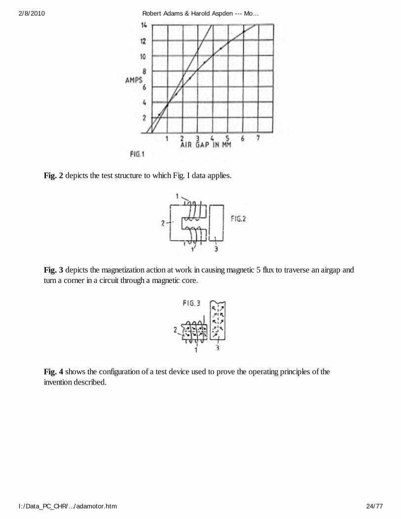
Fig. 2 depicts the test structure to which Fig. I data applies.
Fig. 3 depicts the magnetization action at work in causing magnetic 5 flux to traverse an airgap andturn a corner in a circuit through a magnetic core.
Fig. 4 shows the configuration of a test device used to prove the operating principles of theinvention described.
2/8/2010 Robert Adams & Harold Aspden --- Mo…
I:/Data_PC_CHR/…/adamotor.htm 24/77
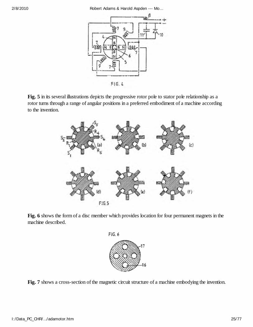
Fig. 5 in its several illustrations depicts the progressive rotor pole to stator pole relationship as arotor turns through a range of angular positions in a preferred embodiment of a machine accordingto the invention.
Fig. 6 shows the form of a disc member which provides location for four permanent magnets in themachine described.
Fig. 7 shows a cross-section of the magnetic circuit structure of a machine embodying the invention.
2/8/2010 Robert Adams & Harold Aspden --- Mo…
I:/Data_PC_CHR/…/adamotor.htm 25/77

Fig. 8 shows a six stator pole configuration with a seven pole rotor and depicts a schematic seriesconnected linking of the magnetizing windings of diametrically opposite stator poles.
Detailed Description of the Invention ~
The fact that one can extract energy from the source which powers the intrinsic ferromagnetic stateis not explicitly evident from existing textbooks, but it is implicit and, indeed, does become explicitonce pointed out, in one textbook authored by F. B. Moullin.
His book The Principles of Electromagnetism published by Clarendon Press, Oxford (3rdEdition, 1955) describes on pages 168-174 an experiment concerned with the effect of air gapsbetween poles in a magnetic circuit. The data obtained are reproduced in Fig. 1, where ProfessorMoullin shows a curve representing a. c. current input for different air gaps, given that the voltagesupplied is constant. In the same figure, Moullin presents the theoretical current that would need tobe applied to sustain the same voltage, and so the related pole forces across the air gap, assuming(a) no flux leakage and (b) that there is complete equality between inductive energy input and themechanical energy potential for the magnetization that is established in the air gap in a quarter-cycleperiod at the a. c. power excitation frequency.
The data show that, even though the level of magnetic polarization is well below the saturationvalue, being confined to a range that is regarded as the linear permeability range in transformerdesign, there is a clear drop-off of current, and so the volt-amp reactive power input needed, as
2/8/2010 Robert Adams & Harold Aspden --- Mo…
I:/Data_PC_CHR/…/adamotor.htm 26/77
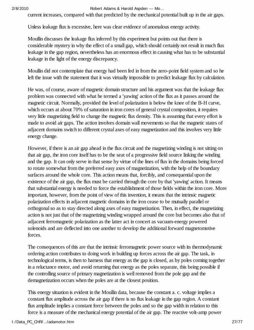
current increases, compared with that predicted by the mechanical potential built up in the air gaps.
Unless leakage flux is excessive, here was clear evidence of anomalous energy activity.
Moullin discusses the leakage flux inferred by this experiment but points out that there isconsiderable mystery in why the effect of a small gap, which should certainly not result in much fluxleakage in the gap region, nevertheless has an enormous effect in causing what has to be substantialleakage in the light of the energy discrepancy.
Moullin did not contemplate that energy had been fed in from the zero-point field system and so heleft the issue with the statement that it was virtually impossible to predict leakage flux by calculation.
He was, of course, aware of magnetic domain structure and his argument was that the leakage fluxproblem was connected with what he termed a 'yawing' action of the flux as it passes around themagnetic circuit. Normally, provided the level of polarization is below the knee of the B-H curve,which occurs at about 70% of saturation in iron cores of general crystal composition, it requiresvery little magnetizing field to change the magnetic flux density. This is assuming that every effort ismade to avoid air gaps. The action involves domain wall movements so that the magnetic states ofadjacent domains switch to different crystal axes of easy magnetization and this involves very littleenergy change.
However, if there is an air gap ahead in the flux circuit and the magnetizing winding is not sitting onthat air gap, the iron core itself has to be the seat of a progressive field source linking the windingand the gap. It can only serve in that sense by virtue of the lines of flux in the domains being forcedto rotate somewhat from the preferred easy axes of magnetization, with the help of the boundarysurfaces around the whole core. This action means that, forcibly, and consequential upon theexistence of the air gap, the flux must be carried through the core by that 'yawing' action. It meansthat substantial energy is needed to force the establishment of those fields within the iron core. Moreimportant, however, from the point of view of this invention, it means that the intrinsic magneticpolarization effects in adjacent magnetic domains in the iron cease to be mutually parallel ororthogonal so as to stay directed along axes of easy magnetization. Then, in effect, the magnetizingaction is not just that of the magnetizing winding wrapped around the core but becomes also that ofadjacent ferromagnetic polarization as the latter act in concert as vacuum-energy poweredsolenoids and are deflected into one another to develop the additional forward magnetomotiveforces.
The consequences of this are that the intrinsic ferromagnetic power source with its thermodynamicordering action contributes to doing work in building up forces across the air gap. The task, intechnological terms, is then to harness that energy as the gap is closed, as by poles coming togetherin a reluctance motor, and avoid returning that energy as the poles separate, this being possible ifthe controlling source of primary magnetization is well removed from the pole gap and thedemagnetization occurs when the poles are at the closest position.
This energy situation is evident in the Moullin data, because the constant a. c. voltage implies aconstant flux amplitude across the air gap if there is no flux leakage in the gap region. A constantflux amplitude implies a constant force between the poles and so the gap width in relation to thisforce is a measure of the mechanical energy potential of the air gap. The reactive volt-amp power
2/8/2010 Robert Adams & Harold Aspden --- Mo…
I:/Data_PC_CHR/…/adamotor.htm 27/77
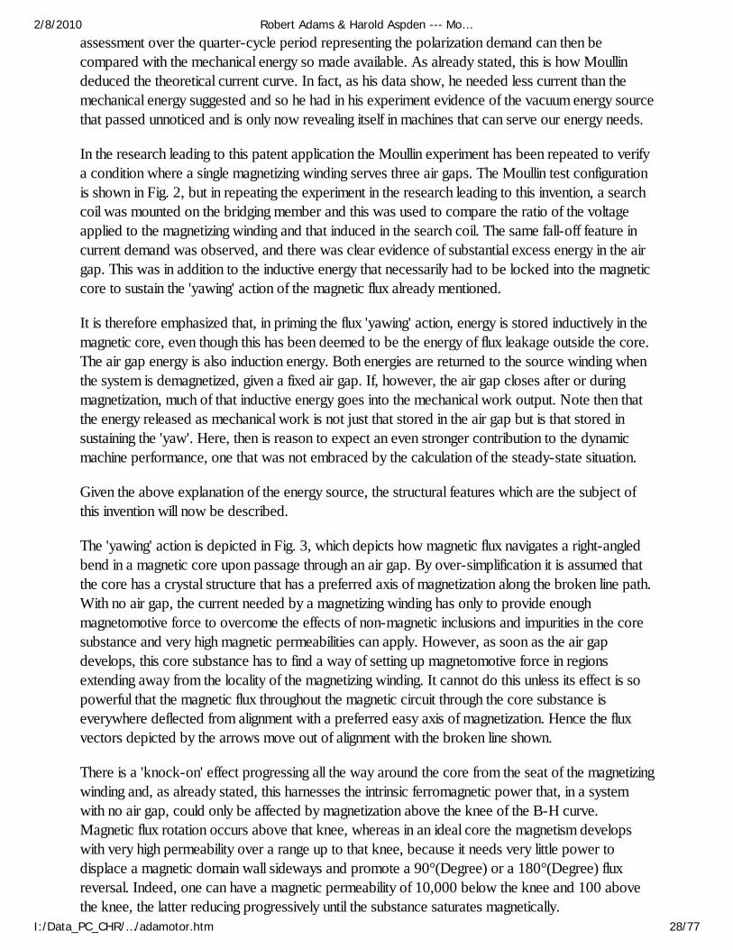
assessment over the quarter-cycle period representing the polarization demand can then becompared with the mechanical energy so made available. As already stated, this is how Moullindeduced the theoretical current curve. In fact, as his data show, he needed less current than themechanical energy suggested and so he had in his experiment evidence of the vacuum energy sourcethat passed unnoticed and is only now revealing itself in machines that can serve our energy needs.
In the research leading to this patent application the Moullin experiment has been repeated to verifya condition where a single magnetizing winding serves three air gaps. The Moullin test configurationis shown in Fig. 2, but in repeating the experiment in the research leading to this invention, a searchcoil was mounted on the bridging member and this was used to compare the ratio of the voltageapplied to the magnetizing winding and that induced in the search coil. The same fall-off feature incurrent demand was observed, and there was clear evidence of substantial excess energy in the airgap. This was in addition to the inductive energy that necessarily had to be locked into the magneticcore to sustain the 'yawing' action of the magnetic flux already mentioned.
It is therefore emphasized that, in priming the flux 'yawing' action, energy is stored inductively in themagnetic core, even though this has been deemed to be the energy of flux leakage outside the core.The air gap energy is also induction energy. Both energies are returned to the source winding whenthe system is demagnetized, given a fixed air gap. If, however, the air gap closes after or duringmagnetization, much of that inductive energy goes into the mechanical work output. Note then thatthe energy released as mechanical work is not just that stored in the air gap but is that stored insustaining the 'yaw'. Here, then is reason to expect an even stronger contribution to the dynamicmachine performance, one that was not embraced by the calculation of the steady-state situation.
Given the above explanation of the energy source, the structural features which are the subject ofthis invention will now be described.
The 'yawing' action is depicted in Fig. 3, which depicts how magnetic flux navigates a right-angledbend in a magnetic core upon passage through an air gap. By over-simplification it is assumed thatthe core has a crystal structure that has a preferred axis of magnetization along the broken line path.With no air gap, the current needed by a magnetizing winding has only to provide enoughmagnetomotive force to overcome the effects of non-magnetic inclusions and impurities in the coresubstance and very high magnetic permeabilities can apply. However, as soon as the air gapdevelops, this core substance has to find a way of setting up magnetomotive force in regionsextending away from the locality of the magnetizing winding. It cannot do this unless its effect is sopowerful that the magnetic flux throughout the magnetic circuit through the core substance iseverywhere deflected from alignment with a preferred easy axis of magnetization. Hence the fluxvectors depicted by the arrows move out of alignment with the broken line shown.
There is a 'knock-on' effect progressing all the way around the core from the seat of the magnetizingwinding and, as already stated, this harnesses the intrinsic ferromagnetic power that, in a systemwith no air gap, could only be affected by magnetization above the knee of the B-H curve.Magnetic flux rotation occurs above that knee, whereas in an ideal core the magnetism developswith very high permeability over a range up to that knee, because it needs very little power todisplace a magnetic domain wall sideways and promote a 90°(Degree) or a 180°(Degree) fluxreversal. Indeed, one can have a magnetic permeability of 10,000 below the knee and 100 abovethe knee, the latter reducing progressively until the substance saturates magnetically.
2/8/2010 Robert Adams & Harold Aspden --- Mo…
I:/Data_PC_CHR/…/adamotor.htm 28/77
In the situation depicted in Figs 2 or 3 the field strength developed by the magnetizing windings 1 onmagnetic core 2 has to be higher, the greater the air gap, in order to achieve the same amount ofmagnetization as measured by the voltage induced in a winding (not shown) on the bridging member3. However, by virtue of that air gap there is potential for harnessing energy supplied to that air gapby the intrinsic zero-point field that accounts for the magnetic permeability being over unity and hereone can contemplate very substantial excess energy potential, give incorporation in a machinedesign which departs from convention.
One of the applicants has built an operative test machine which is configured as depictedschematically in Fig. 4. The machine has been proved to deliver substantially more mechanicalpower output than is supplied as electrical input, as much as a ratio of 7:1 in one version, anc it canact regeneratively to produce electrical power.
What is shown in Fig. 4 is a simple model designed to demonstrate the principle of operation. Itcomprises a rotor in which four permanent magnets 4 are arrayed to form four poles. The magnetsare bonded into four sectors of a non-magnetic disc 5 using a high density polyurethane foam fillerand the composite disc is then assembled on a brass spindle 6between a split flange coupling. Notshown in the figure is the structure holding the spindle vertically in bearings or the star wheelcommutator assembly attached to the upper shaft of the spindle.
Note that the magnets present north poles at the perimeter of the rotor disc and that the south polesare held together by being fimly set in the bonding material.
A series of four stator poles were formed using magnetic cores from standard electromagneticrelays are were positioned around the rotor disc as shown. The magnetizing windings 7 on thesecores are shown to be connected in series and powered through commutator contacts 8 by a d. c.power supply. Two further stator cores formed by similar electromagnetic relay components aredepicted by their windings 9 in the intermediate angle positions shown and these are connected inseries and connected to a rectifier 10 bridged by a capacitor 11.
The rotor spindle 6 is coupled with a mechanical drive (not shown) which harnesses the torquedeveloped by the motor thus formed and serves as a means for measuring output mechanical powerdelivered by the machine.
In operation, assuming that the rotor poles are held initially off-register with the corresponding statorpoles and the hold is then released, the strong magnetic field action of the permanent magnets willturn the rotor to bring the stator and rotor poles into register. A permanent magnet has a strongattraction for soft iron and so this initial impulse of rotation is powered by the potential energy of themagnets.
Now, with the rotor acting as a flywheel and having inertia it will have a tendency to over-shoot thein-register pole position and that will involve a reverse attraction with the result that the rotor willoscillate until damping action brings it to rest. However, if the contacts of the commutating switchare closed as the poles come first into register, the magnetizing windings 7 will receive a currentpulse which, assuming the windings are connected in the right sense, tends to demagnetize the fourstator cores. This means that, as the stator and rotor poles separate, the reverse attraction by the
2/8/2010 Robert Adams & Harold Aspden --- Mo…
I:/Data_PC_CHR/…/adamotor.htm 29/77

magnets is eliminated. Indeed, if the demagnetizing current pulses supplied to the windings 4 arestrong enough, the stator poles can reverse polarity and that results in a repulsion giving forwarddrive to the separating rotor poles.
The net result of this action is that the rotor will continue rotating until it passes the dead centreangular position which allows the rotor to be attracted in the forward direction by the stator poles90°(Degree) forward of those acting originally.
The commutating switch 8 needs only to be closed for a limited period of angular travel followingthe top dead centre in-register position of the stator and rotor poles. The power supplied throughthat switch by those pulses will cause the rotor to continue rotating and high speeds will be achievedas the machine develops its full motor function.
Tests on such a machine have shown that more mechanical power can be delivered than is suppliedelectrically by the source powering the action through the commutating switch. The reason for this isthat, whereas the energy in the air gap between rotor and stator poles which is tapped mechanicallyas the poles come into register is provided by the intrinsic power of the ferromagnet, ademagnetizing winding on the part of the core system coupled across that air gap needs very littlepower to eliminate the mechanical force acting across that air gap. Imagine such a winding on thebridging member shown in Fig. 2. The action of current in that winding, which sits astride the'yawing' flux in that bridging member well removed from the source action of the magnetizingwindings 1, is placed to be extremely effective in resisting the magnetizing influence communicatedfrom a distance. Hence very little power is needed to overcome the magnetic coupling transmittedacross the air gap.
Although the mutual inductance between two spaced-apart magnetizing windings has a reciprocalaction, regardless of which winding is primary and which is secondary, the action in the particularmachine situation being described involves the 'solenoidal' contribution represented by the 'yawing'ferromagnetic flux action. The latter is not reciprocal inasmuch as the flux 'yaw' depends on thegeometry of the system. A magnetizing winding directing flux directly across an air gap has adifferent influence on the action in the ferromagnetic core from one directing flux lateral to the airgap and there is no reciprocity in this action.
In any event, the facts of experiment do reveal that, owing to a significant discrepancy in suchmutual interaction, more mechanical power is fed into the rotor than is supplied as input from theelectrical source.
This has been further demonstrated by using the two stator windings 9 to respond in a generatorsense to the passage of the rotor poles. An electrical pulse is induced in each winding by thepasssage of a rotor pole and this is powered by the inertia of the rotor disc 5. By connecting thepower so generated to charge the capacitor 11 the d. c. power supply can be augmented toenhance the efficiency even further. Indeed, the machine is able to demonstrate the excess powerdelivery from the ferromagnetic system by virtue of electrical power generation charging a battery ata greater rate than a supply battery is discharged.
This invention is concerned with a practical embodiment of the motor-generator principles justdescribed and aims, in its preferred aspect, to provide a robust and reliable machine in which the
2/8/2010 Robert Adams & Harold Aspden --- Mo…
I:/Data_PC_CHR/…/adamotor.htm 30/77

tooth stresses in the rotor poles, which are fluctuating stresses communicating high reluctance drivetorque, are not absorbed by a ceramic permanent magnet liable to rupture owing to its brittlecomposition.
Another object is to provide a structure which can be dismantled and reassembled easily to replacethe permanent magnets, but an even more important object is that of minimizing the stray leakageflux oscillations from the powerful permanent magnets. Their rotation in the device depicted in Fig. 4would cause excessive eddy-current induction in nearby metal, including that of the machine itself,and such effects are minimized if the flux changes are confined to paths through steel laminations andif the source flux from the magnets has a symmetry or near symmetry about the axis of rotation.
Thus, the ideal design with this in mind is one where the permanent magnet is a hollow cylinderlocated on a non-magnetic rotor shaft, but, though that structure is within the scope of this invention,the machine described will utilize several separate permanent magnets approximating, in function,such a cylindrical configuration.
Referring to Fig. 4, it will further be noted that the magnetic flux emerging from the north poles willhave to find its way along leakage paths through air to re-enter the south poles. For periods in eachcycle of machine operation the flux will be attracted through the stator cores, but the passagethrough air is essential and so the power of the magnets is not used to full advantage and there arethose unwanted eddy-current effects.
To overcome this problem the invention provides for two separate rotor sections and the statorpoles become bridging members, which with optimum design, allow the flux from the magnets tofind a route around a magnetic circuit with minimal leakage through air as the flux is directed throughone or other pairs of air gaps where the torque action is developed.
Reference is now made to Fig. 5 and the sequence of rotor positions shown. Note that the statorpole width can be significantly smaller that that of the rotor poles. Indeed, for operation using theprinciples of this invention, it is advantageous for the stator to have a much smaller pole width so asto concentrate the effective pole region. A stator pole width of half that of the rotor is appropriatebut it may be even smaller and this has the secondary advantage of requiring smaller magnetizingwindings and so saving on the loss associated with the current circuit.
The stator has eight pole pieces formed as bridging members 12, more clearly represented in Fig. 7,which shows a sectional side view through two rotor sections 13 axially spaced on a rotor shaft 14.There are four permanent magnets 15 positioned between these rotor sections and located inapertures 16 in a disc 17 of a non-magnetic substance of high tensile strength, the latter beingshown in Fig. 6. The rotor sections are formed from disc laminations of electrical steel which hasseven large teeth, the salient poles. Magnetizing windings 18 mounted on the bridging members 12constitute the system governing the action of the motor-generator being described.
The control circuitry is not described as design of such circuitry involves ordinary skill possessed bythose involved in the electrical engineering art.
It suffices, therefore, to describe the merits of the structural design configuration of the coreelements of the machine. These concern principally the magnetic action and, as can be imagined
2/8/2010 Robert Adams & Harold Aspden --- Mo…
I:/Data_PC_CHR/…/adamotor.htm 31/77
from Fig. 7, the magnetic flux from the magnets enters the rotor laminations by traversing the planarfaces of the laminations and being deflected into the plane of the laminations to pass through one orother of the stator pole bridging members, returning by a similar route through the other rotor.
By using eight stator poles and seven rotor poles, the latter having a pole width equal to half thepole pitch in an angular sense, it will be seen from Fig. 5, that there is always a flux passage acrossthe small air gap between stator and rotor poles. However, as one pole combination is in-registerthe diametrically-opposed pole combinations are out-of-register.
As described by reference to Fig. 4 the operation of the machine involves allowing the magnet topull stator and rotor poles into register and then, as they separate, pulsing the winding on therelevant stator member to demagnetize that member. In the Fig. 4 system, all the stator magnetizingwindings were pulsed together, which is not an optimum way in which to drive a multi-polemachine.
In the machine having the pole structure with one less rotor pole than stator poles (or an equivalentdesign in which there is one less stator pole than rotor poles) this pulsing action can be distributed inits demand on the power supply, and though this makes the commutation switch cicuit moreexpensive the resulting benefit outweighs that cost.
However, there is a feature of this invention by which that problem 15 can be alleviated if noteliminated.
Suppose that the rotor has the position shown in Fig. 5(a) with the rotor pole denoted R1 midwaybetween stator poles S1 and S2 imagine that this is attracted towards the in-register position withstator pole S2. Upon reaching that in-register position, as shown in Fig. 5 (c), suppose that themagnetizing winding of stator pole S2 is excited by a current pulse which is sustained until the rotorreaches the Fig. 5(e) position. The combination of these two actions will have imparted a forwarddrive impulse powered by the permanent magnet in the rotor structure and the current pulse whichsuppresses braking action will have drawn a smaller amount of energy from the electrical powersource that supplies it. This is the same process as was described by reference to Fig. 4.
However, now consider the events occurring in the rotor action diametrically opposite that justdescribed. In the Fig 5(a) position rotor pole R4 has come fully into register with stator pole S5 andso stator pole S5 is ready to be demagnetized. However, the magnetic coupling between the rotorand stator poles is then at its strongest. Note, however, that in that Fig. 5(a) position R5 isbeginning its separation from stator pole S6and the magnetizing winding of stator pole S6 must thenbegin draw power to initiate demagnetization. During that following period of pole separation thepower from the magnet is pulling R1 and S2 together with much more action than is needed togenerate that current pulse needed to demagnetize S6. It follows, therefore, that, based on theresearch findings of the regenerative excitation in the test system of Fig. 4, the series connection ofthe magnetizing windings on stators S2 and S6 will, without needing any commutative switching,provide the regenerative power needed for machine operation.
The complementary action of the two magnetizing windings during the pole closure and poleseparation allows the construction of a machine which, given that the zero-point vacuum energypowering the ferromagnet is feeding input power, will run on that source of energy and thereby cool
2/8/2010 Robert Adams & Harold Aspden --- Mo…
I:/Data_PC_CHR/…/adamotor.htm 32/77
the sustaining field system.
There are various design options in implementing what has just been proposed. Much dependsupon the intended use of the machine. If it is intended to deliver mechanical power output theregenerative electrical power action can all be used to power the demagnetization with any surpluscontributing to a stronger drive torque by reversing the polarity of the stator poles during poleseparation.
If the object is to generate electricity by operating in generator mode then one could design amachine having additional windings on the stator for delivering electrical power output. However, itseems preferable to regard the machine as a motor and maximize its efficiency in that capacity whilstusing a mechanical coupling to an alternator of conventional design for the electrical powergeneration function. In the latter case it would still seem preferable to use the self-excitation featurealready described to reduce commutation switching problems.
The question of providing for machine start-up can be addressed by using a separate starter motorpowered from an external supply or by providing for current pulsing limited to, say, two statorpoles. Thus, for example, with the eight stator pole configuration, the cross-connected magnetizingwindings could be limited to three stator pairs, with two stator magnetizing windings left free forconnection to a pulsed external supply source.
If the latter feature were not required, then the stator magnetizing windings would all be connectedin pairs on a truly diametrically opposite basis. Thus Fig. 8 shows a rotor-stator configuration havingsix stator poles interacting with seven rotor poles and stator magnetizing windings linked together inpairs.
The invention, therefore, offers a wide range of implementation possibilities, which, in the light of thisdisclosure will become obvious to persons skilled in the electrical engineering art, all based,however, on the essential but simple principle that a rotor has a set of poles of common polaritywhich are attracted into register with a set of stator poles that are suppressed or reversed in polaritymagnetically during pole separation. The invention, however, also offers the important feature ofminimizing commutation and providing further for a magnetic flux closure that minimizes the leakageflux and fluctuations of leakage flux and so contributes to efficiency and high torque performance aswell as durability and reliability of a machine incorporating the invention.
It is noted that although a machine has been described which uses two rotor sections it is possibleto build a composite version of the machine having several rotor sections. In the eventuality that theinvention finds use in very large motor-generator machines the problem of providing very largemagnets can be overcome by a design in which numerous small magnets are assembled. Thestructural concept described by reference to Fig. 6 in providing locating apertures to house themagnets makes this proposal highly feasible. Furthermore, it is possible to replace the magnets by asteel cylinder and provide a solenoid as part of the stator structure and located between the rotorsections. This would set up an axial magnetic field magnetizing the steel cylinder and so polarizingthe rotor. However, the power supplied to that solenoid would detract from the power generatedand so such a machine would not be as effective as the use of permanent magnets such as are nowavailable. Nevertheless, should one see significant progress in the development of warmsuperconductor materials, it may become feasible to harness the self-generating motor-generator
2/8/2010 Robert Adams & Harold Aspden --- Mo…
I:/Data_PC_CHR/…/adamotor.htm 33/77
features of the invention, with its selfcooling properties, by operating the device in an enclosure atlow temperatures and replacing the magnets by a superconductive statorsupported solenoid.
Claims ~
(1) An electrodynamic motor-generator machine comprising a stator configured to provide a set ofstator poles, a corresponding set of magnetizing windings mounted on the stator pole set, a rotorhaving two sections each of which has a set of salient pole pieces, the rotor sections being axiallyspaced along the axis of rotation of the rotor, rotor magnetization means disposed between the tworotor sections arranged to produce a unidirectional magnetic field which magnetically polarizes therotor poles, whereby the pole faces of one rotor section all have a north polarity and the pole facesof the other rotor section all have a south polarity and electric circuit connections between anelectric current source and the stator magnetizing windings arranged to regulate the operation of themachine by admitting current pulses for a duration determined according to the angular position ofthe rotor, which pulses have a direction tending to oppose the polarization induced in the stator bythe rotor polarization as stator and rotor poles separate from an in-register position, whereby theaction of the rotor magnetization means provides a reluctance motor drive force to bring stator androtor poles into register and the action of the stator magnetization windings opposes the counterpartreluctance braking effect as the poles separate.
(2) A motor-generator according to claim 1, wherein the circuit connecting the electric currentsource and the stator magnetizing windings is designed to deliver current pulses which are ofsufficient strength and duration to provide demagnetization of the stator poles as the stator and rotorpoles separate from an in-register position.
(3) A motor-generator according to claim 1, wherein the circuit connecting the electric currentsource and the stator magnetizing windings is designed to deliver current pulses which are ofsufficient strength and duration to provide a reversal of magnetic flux direction in the stator poles asthe stator and rotor poles separate from an in-register position, whereby to draw on powersupplied from the electric current source to provide additional forward drive torque.
(4) A motor-generator according to claim 1, wherein the electric current source connected to astator magnetizing winding of a first stator pole comprises, at least partially, the electrical pulsesinduced in the stator magnetizing winding of a different second stator pole, the stator pole setconfiguration in relation to the rotor pole set configuration being such that the first stator pole iscoming into register with a rotor pole as the second stator pole separates from its in-registerposition with a rotor pole.
(5) A motor-generator according to claim 1, wherein the number of poles in a set of stator poles isdifferent from the number of rotor poles in each rotor section.
(6) A motor-generator according to claim I, wherein the stator configuration provides pole pieceswhich are common to both rotor sections in the sense that when stator and rotor poles are in-register the stator pole pieces constitute bridging members for magnetic flux closure in a magneticcircuit including that of the rotor magnetization means disposed between the two rotor sections.
(7) A motor-generator according to claim 6, wherein the number of poles in a set of stator poles
2/8/2010 Robert Adams & Harold Aspden --- Mo…
I:/Data_PC_CHR/…/adamotor.htm 34/77
and the number of rotor poles in each section do not share a common integer factor and the numberof rotor poles in one rotor section is the same as that in the other rotor section.
(8) A motor-generator according to claim 7, wherein the number of poles in a stator set and thenumber of poles in a rotor section differs by one and the pole faces are of sufficient angular width toassure that the magnetic flux produced by the rotor magnetization means can find a circuitalmagnetic flux closure route through the bridging path of a stator pole and through correspondingrotor poles for any angular position of the rotor.
(9) A motor-generator according to claim 8, wherein each rotor section comprises seven poles.
(10) A motor-generator according to claim 7, wherein there are N rotor poles in each rotor sectionand each has an angular width that is 180/N degree of angle.
(11) A motor-generator according to claim 7, wherein the stator pole faces have an angular widththat is no greater than half the angular width of a rotor pole.
(12) A motor-generator according to claim 1, wherein the rotor sections comprise circular steellaminations in which the rotor poles are formed as large teeth at the perimeter, and the rotormagnetization means comprise a magnetic core structure the end faces of which abut twoassemblies of 20 such laminations forming the two rotor sections.
(13) A motor-generator according to claim 1 in which the rotor magnetization means comprises atleast one permanent magnet located with its polarization axis parallel with the rotor axis.
(14) A motor-generator according to claim 13, wherein an apertured metal disc that is of a non-magnetizable substance is mounted on a rotor shaft and positioned intermediate the two rotorsections and each aperture provides location for a permanent magnet, whereby the centrifugalforces acting on the permanent magnet as the rotor rotates are absorbed by the stresses set up inthe disc.
(15) A motor-generator according to claim 1, having a rotor mounted on a shaft that is of a non-magnetizable substance, whereby to minimize 5 magnetic leakage from the rotor magnetizing means.
(16) An electrodynamic motor-generator machine comprising a stator configured to provide a set ofstator poles, a corresponding set of magnetizing windings mounted on the stator pole set, a rotorhaving two sections each of which has a set of salient pole pieces, the rotor sections being axiallyspaced along the axis of rotation of the rotor, rotor magnetization means incorporated in the rotorstructure and arranged to polarize the rotor poles, whereby the pole faces of one rotor section allhave a north polarity and the pole faces of the other rotor section all have a south polarity andelectric circuit connections between an electric current source and the stator magnetizing windingsarranged to regulate the operation of the machine by admitting current pulses for a durationdetermined according to the angular position of the rotor, which pulses have a direction tending tooppose the polarization induced in the stator by the rotor polarization as stator and rotor polesseparate from an in-register position, whereby the action of the rotor magnetization means providesa reluctance motor drive force to bring stator and rotor poles into register and the action of thestator magnetization windings opposes the counterpart reluctance braking effect as the poles
2/8/2010 Robert Adams & Harold Aspden --- Mo…
I:/Data_PC_CHR/…/adamotor.htm 35/77
separate.
(17) A motor- generator according to claim 16, wherein the electric current source connected to astator magnetizing winding of a first stator pole comprises, at least partially, the electrical pulsesinduced in the stator magnetizing winding of a different second stator pole, the stator pole setconfiguration in relation to the rotor pole set configuration being such that the first stator pole iscoming into register with a rotor pole as the second stator pole separates from its in-registerposition with a rotor pole.
Amendments to the Claims:
(1) An electrodynamic motor-generator machine comprising a stator configured to provide a set ofstator poles, a corresponding set of magnetizing windings mounted on the stator pole set, a rotorhaving two sections each of which has a set of salient pole pieces, the rotor sections being axiallyspaced along the axis of rotation of the rotor, rotor magnetization means disposed between the tworotor sections arranged to produce a unidirectional magnetic field which magnetically polarizes therotor poles, whereby the pole faces of one rotor section all have a north polarity and the pole facesof the other rotor section all have a south polarity and electric circuit connections between anelectric current source and the stator magnetizing windings arranged to regulate the operation of themachine by admitting current pulses for a duration determined according to the angular position ofthe rotor, which pulses have a direction tending to oppose the polarization induced in the stator bythe rotor polarization as stator and rotor poles separate from an in-register position, whereby theaction of the rotor magnetization means provides a reluctance motor drive force to bring stator androtor poles into register and the action of the stator magnetization windings opposes the counterpartreluctance braking effect as the poles separate, the machine being characterized in that the statorcomprises separate ferromagnetic bridging members mounted parallel with the rotor axis, the endsof which constitute stator poles and the core sect ions of which provide cross-section disposedantiparallel with the unidirectional magnetic field polarization axis of the rotor magnetizing means.
(2) A motor-generator according to claim 1, wherein the circuit connecting the electric currentsource and the stator magnetizing windinga is designed to deliver current pulses which are ofsufficient strength and duration to provide demagnetization of the stator poles as the stator and rotorpoles separate from an in-register position.
(3) A motor-generator according to claim 1, wherein the circuit connecting the electric currentsource and the stator magnetizing windings is designed to deliver current pulses which are ofsufficient strength and duration to provide a reversal of magnetic flux direction in the stator poles asthe stator and rotor poles separate from an in- register position, whereby to draw on powersupplied from the electric current source to provide additional forward drive torque.
(4) A motor-generator according to claim 1, wherein the electric current source connected to astator magnetizing winding of a first stator pole comprises, at least partially, the electrical pulsesinduced in the stator magnetizing winding of a different second etator pole, the stator pole setconfiguration in relation to the rotor pole set configuration being such that the first stator pole iscoming into register with a rotor pole as the second stator pole separates from its in-registerposition with a rotor pole.
2/8/2010 Robert Adams & Harold Aspden --- Mo…
I:/Data_PC_CHR/…/adamotor.htm 36/77

(5) A motor-generator according to claim 1, wherein the number of poles in a set of atator poles isdifferent from the number of rotor poles in each rotor section.
(6) A motor-generator according to claim 1, wherein the stator configuration provides pole pieceswhich are common to both rotor sections in the sense that when stator and rotor poles are in-register the stator pole pieces constitute bridging members for magnetic flux closure in a magneticcircuit including that of the rotor magnetization means disposed between the two rotor sections.
(7) A motor-generator according to claim 6, wherein the number of poles in a set of stator polesand the number of rotor poles in each section do not share a common integer factor and the numberof rotor poles in one rotor section is the same as that in the other rotor section.
Search Examiner: J. COCKITT
Categories of documents: X: Document indicating lack of novelty or of inventive step. A: Document indicating technological background and/or state of the art.
Category Identity of document and relevant passages Relevant to claim(s): X GB 0547668 A (HITCHCOCK) see page 6 lines 54 to 71; Figures 6, 7 1-3, 6, 12-14, 16 at least X US 4972112 A (KIM) see whole document 1-3 at least A US 4873463 A (JONES)
Revelation of the Myths of "Unity" & Beyond
Over 5 years ago I made a reference in a chapter of my book 'The Revelation of the Century' inrelation to claims on "over 100% efficiency". In this book, which is still being distributed worldwideby Nexus Magazine, Publisher of Queensland, Australia, reference is made to what is erroneouslytermed "zero point" or "beyond unity". On page 14, second to last paragraph, I quoted:
I do not subscribe to the definition of 'beyond unity'. There simply cannot be any such state, as thetotality of the Universe is 'Unity'.
In support of my reference, I have now expanded upon this matter in this new Second Edition2001. Now I am going to discuss this subject in more depth, and my revelations here will no doubtshatter the minds of many electrical engineers and scientists worldwide, because they have got it allwrong!
To start with, in orthodox teachings, we have the word "efficiency" used extensively in relation toelectrical machines and devices, etc. So too, we now have the definition of 'over 100% efficiency'bandied around extensively. Now, this term 'efficiency', insofar as orthodox teachings areconcerned, applies only to calculations to 100% and beyond. Now that most of the scientific worldare now beginning to accept the possibility of 'over 100% efficiency', this, in turn, has now alsospilled over into using the terms of 'unity', 'beyond unity', 'negative energy', 'zero point', etc. Theseterms do not necessarily apply because here, in fact, is just where reality comes into the act. For
2/8/2010 Robert Adams & Harold Aspden --- Mo…
I:/Data_PC_CHR/…/adamotor.htm 37/77
instance, if we have a machine or device displaying an input of 100 watts and an output of 500watts, this equals 500%. This is so, but it only indicates the degree of performance calculated at theend of the day. The shattering truth of the matter is that the device is not necessarily operating in therealm of 'unity', let alone over unity, zero point, negative time, etc. However, a machine or devicethat "measures" over 100% and displays energy "growth" effects, with "time", which are "additive"and "accumulative", then this is "not" conventional science, but science of another dimension - this isUNITY! So, therefore, a machine or device which does not display the aforegoing effects, is not aunity or over unity device, as is too often claimed. This kind of evidence outlined above is, in myknowledge of science, the "only" method by which the violation of the Law of Conservation can beproven. Ever expanding energy, akin to the now proven and accepted evidence of the Expansion ofthe Universe.
On The Matter of Excess Heat Manifestation
The permanent magnet rotor of the Adams Machine is of the only type of its kind in the world and,due to its unusual materials and their geometric placements, the rotor of the Adams Machineremains cool and, at most, rises only three to five degrees Celsius above ambient under full load!The rare earth magnets of the rotor are therefore protected from destruction due to excessive heatwhich would be inevitable in a very short period of time in a, for instance, large version of theFaraday Machine, and others I could mention. Faraday was brilliant in that he well knew thedisadvantages and problems to be faced in attempting to put the discovery of this puny quantity ofenergy to work, by simply discarding it as a useless oddity, where it should have remained. Timehas proven that hundreds of people worldwide have attempted to construct a viable Faradaymachine and have all failed to prove excess energy presence, except for Tewari and Inomatu, whostill have the problem of harnessing the high current efficiently without the use of lethal Mercury andthe dispersement of excessive heat manifesting within the machine rotor.
The Energy Metamorphosis
It is my confirmed opinion that we are now into a major revolution in science and technology. Newsystems are almost a daily occurrence, major breakthroughs are coming on stream at a very fastpace and on a regular basis. Such are some of the breakthroughs that their effects on our civilisationwill defy description. Superluminal energy production that is clean, economical and safer is nowhere.
The sooner people learn that the genius of man is, in reality, the genius of our Creator and it isunlimited, the better it will be for mankind. To believe otherwise is to state that our Creator's geniusis limited. Our Creator's genius is not limited - it is the false teachings of physics bandied out by themind of man in our Universities and Colleges alike that is limited. The laws of physics, as they standtoday, are little but convenient assumptions ("if it works, leave it alone" kind of thinking), where truescience (progressive science) abides by the Laws of Nature. This is why we humans are fullycapable of applying the Laws of Nature to physics in our new dimension of thought, but still appearreluctant to deprogram when it comes to the orthodox and almost religious dogmas of past andsacrosanct principles of man-made scientific notions. Our Universe is negentropically organised and
2/8/2010 Robert Adams & Harold Aspden --- Mo…
I:/Data_PC_CHR/…/adamotor.htm 38/77
is proceeding transfinitely from disorder to order. It was until recent times it was accepted wisdomthat the sun revolved around the earth and your life depended upon believing it!
Nexus Magazine (August-September 1993)
The Adams Pulsed Electric Motor Generator --- Update
Robert Adams of New Zealand Outlines Magnetic Polarity Reversal & His Discoveries
As the inventor of the `Adams Bulsed Electric Motor Generator', I write this treatise with a view tokeeping it uncluttered from unnecessary thcories and mathematics, so that all who read this article,whether they be enthusiasts, engineers or scientists, are able to follow the text, together with itsdrawings, describing the sequences in various stages of operation of the `Adams AdvancedPEMG'.
My various discoveries cover over twenty-five years in the fields of electrical rotary machines, witha total of over sixty years involvement in communications, broacasting and electrical engineering.
It is my desire that as many free energy enthusiasts as possible get into the act of building myoriginal machine whilst, at the same time, conducting their own research. Several people in differentcountries have already succeeded in building the machine in its original form, as has been outlined inthe "Adams Manual", with beyond-unity results. After obtaining satisfying results from the originalversion, one would then be better equipped to handle the more stringent requirements of the'Advanced', or 'Mark II' version. A lot of material in this treatise pertains to this 'Mark II' version,i.e., the 'Adams Advanced Motor Generator'.
Losses In Electrical Machines ~
Losses in conventional electrical machines are too high and are due to magnetic drag, eddy currentsand hysterisis, and consequent high operating temperatures.
It was with the above problerms in mind that I was prompted to fid a way of overcoming theaforementioned losses, the result of which evolved in a machine of beyond-unity capabilities.
As the `Adanis Motor' is a pulsed direct-current device, there is no change in polarity of theexternal source; therefore there are no eddy current losses, and hysterisis loss in the motor isminuscule; with new matials becoming available for stators, the small loss incurred would disapear.It matters little, however, as the machine efficiency is such that such a minuscule loss is negligible.
With reference to magnetic drag, this too is virtually non-existent, due to the unique design of themachine. A rotor pole, upon leaving the attraction area of the stator, is at a precise geometricalpoint - and is suddenly repulsed, thus overcoming any possibility of magnetic drag taking place.
Having outlined the above, I will now explain something regarding magnetic drag that won't befound in classical teachings or texts: a rotor, once in motion, is mutually attracted to any stator in its
2/8/2010 Robert Adams & Harold Aspden --- Mo…
I:/Data_PC_CHR/…/adamotor.htm 39/77
path. On leaving the stator area, however, the stator causes a drag-back effect - classical teachingsdo tell you that much. What classical teaching does not tell you is that the energy in the initialattraction equals exactly that which causes the drag upon leaving the stator area. This is whereclassical teaching is found wanting. The original attraction and secondary attraction exactly cancelone another out. Magnetic drag, therefore, does not exist in the straight motor version of the`Adams Motor' invention. The machine is pulsed before the trailing edge of the rotor magnet can beaffected. Should the timing be a littie out, the effect would be minuscule.
Having discussed the aforementioned factors, there is littie to explain regarding the very lowoperating temperature of the `Adams Motor', as a result of which it does not require the use of acooling fan with its own efficiency loss to counter.
It has been noted in New Energy News under the title "High Current Brushes", on making use ofsilver and platinum for commutator and points: this news is not news to me as, during my research in1976,1 used these materials myself for the above purpose. It appears, however, from this articlesubmitted to New Energy News that the method for their use, being researched, has goodprospects. I, for one, look forward to learning of the progress in this direction.
In 1976 I learnt of the high losses of my commutator system and first used silver for the star discand platinum for the points with considerable success, and having since used photo and magneticswitching with remarkable success. Having, of course, kept my research and experimentation tomyself over the past two decades for reasons associatetl in the main with the establishment, andlatterly with interationall patent law, I was forced to withhold all my machine's secrets up until myrecent decision to publish certain aspects of my work earlier this year.
Recent Discovery by the Author ~
One would expect magnetic polarity reversal to be instantaneous in a rotary machine between rotormagnet and stator. However, this is not so. I have recently discovered that the reversal isexponential in tnansition from one polarity to another. When this occurs, the magnetic radiation ofthe rotor pole/s doubles and, with no external power aIplied, there is no magnetism in the statorpole - so it becomes patently logical that the extra energy can only be from the ether (negative-time-nergy).
Engineering Into Negative Time & Negative Energy ~
In the realms of engineering negative energy and negative time, I have anticipated there would be anew world of discoveries at hand and answers to be found to certain phenomna taking place, towhich we have all previously been unaccustomed. This anticipation has manifested itself all too soonas, since my first successfull recent attempts at engineering anti-gravity have proven, someinteresting phenomena have become revealed, one of which is the process of magnetic polarityreversal, or conversion.
In an endeavour to discover what actually takes place during this 'conversion' of magnetic polarity, Iused a magnetic polarity indicator and compass, but both proved worthless, as they simply huntedback and forth due to the pulses of magnetic fields from the machine being in motion.
2/8/2010 Robert Adams & Harold Aspden --- Mo…
I:/Data_PC_CHR/…/adamotor.htm 40/77
Subsequent to this attempt, I had meanwhile mude an important discovery concerning magneticpolarity reversal, in that it was not necessary that the machihe he in motion or apply any externalenergy in oreder for it to bring about the magnetic polarity reversal. From this discovery, I becameconfident that I further discovered what actually takes place in this region in relation to the reversalphenomenon. In order to implement a test on this, I determined that a slow movement of the rotorby hand would indicate, on the instruments, what would he taking place. This exercise did indeedprove to be of substance, and I will now, here, graphically portray the results.
To deliver power, however, from the negative energy/negative time region, the machine must be inmotion and, preferably, operating at certain harmonic speeds. The accompanying drawings give aphysical description of the magnetic actions taking place as the rotor magnet reaches the stator andcommenes to traverse though the negative energy/negative time region.
In a 180 degree configuration, with two stator poles, the same actions take place simultaneously inreverse magnetic polarity order (as Drawing TD-GOOl, Figure 2, pointers A and B indicate).
Actions Taking Place in the Adams Advanced (Mark II) Motor Generator ~
(1) A rotor south pole, upon approaching an open cincuit stator, is mutually attracted to it, asdepicted by Drawing TD-G004, Figure A. [ These figures are missing ]
(2) When the leading edge of a south pole reaches the edge of a stator (Figure B), it appears, as itbegins to move inwards, that the south polarity of the rotor pole is being exponentially reversed tonorth. In addition, the stator now becomes a temponary magnet, also exponentially becorning anorth pole (Figure C). Meanwhile, the rotor magnet is still being attracted up to point zero of thestator (Figure D) and, as the leading edge of the rotor moves from point zero of the stator second-half region (Figure E), it appears that the north polarity strength is now increasing exponentially inthis region and, on becoming parallel, i.e. reaching each other face-to-face (Figure F), the mageticpolarity reversal is then complete, and both magnet and stator poles are at north polarity. lt is in thisregion now that the state of and-gravity and negative time exists, with two magnets of like polesattracting each other and creating a gravitational repulsive force at the completion of the magneticpolarity reversal cycle.
There is a specific point of `x' from the stator centre where the machine is pulsed (refer DrawingTD-G001, Figure 1, A & B, pulse angle). Fine tuning the timing at this geometrical point, themachine passes into a state of electromotive resonance where input power drops dramatically andshaft power increases in the negative time and negative energy region.
In all, the machine benefits from four different force actions per revolution and paying a minusculetoll fee for only one.
Firstly, as depicted by Figure A of Drawing TD-G004, the rotor magnet is mutually attracted to thestator (gets away without paying for that - explained elsewhere - refer paragraph 4 in sectionheaded 'Losses in Electrical Machines'). Secondly, the attraction of the gravitational repulsionforces in the anti- gravity area (as illustrated in Drawing TD-G001, Figure 2, at arrows A & B).Thirdly, from the repulsion pulse of the stator at point `x' (refer to pulse angle of Drawing TD-G001, Figure 1).
2/8/2010 Robert Adams & Harold Aspden --- Mo…
I:/Data_PC_CHR/…/adamotor.htm 41/77

Fourthly, the rotor is given a further pulse from the collapsing field (a few degrees from potra `x' inFigure 1).
For maximum possible results from the `Adams Advanced (Mark II) Motor', it is necessary toapply harmonic/resonance equations for the calculation of all parameters including speeds andfrequency. With the foregoing parameters met, it is recommended to engage magnetic or photoswitching with its low loss, high efficiency properties. Drawing TD-G002, on the left, illustrates apositive `untuned state' and, on the right of the same drawing, a `tuned resonant state', together witha graph showing relative polarity change with component dimension changes. The area within thelower circle of the system indicates both poles are at north polarity (note the two curved arrows ateach side of the magnet pole which depict the change that is/has taken place in the negative-timearea).
It is possible to engineer the `Adams Advanced (Mark II) PEMG' in such a way that a machine ofany desired efficiency may be constructed from 100% up to four figures and beyond.
The term `efficiency' now becomes a matter to be addressed, which I have done in the sectionheaded `Free-Energy Devices and the Term `Efficiency' and its Connotations'.
Permanent Magnets & Work ~
Permanent magnets do not and can not `do work' --- as claimed by certain people.
It is the ether/gravity forces which cause immense attraction and/or repulsion to take place betweena permanent magnet and other magnetic material. It is these ether forces that, combining with thecaptive permanent magnet fields, harness the energy of gravity ether forces, so often erroneouslyreferred to as `work' `done by magnets' (refer to notes on Nikola Tesla at the end of this section).
The magnets in this situation are simply acting `as a gate', making way to the ether for thecollection/release of gravitational/ether energy. The pemanent magnet is a component in the system,operating as a `gating device', as explained elsewhere in my writing --- the magnet does notgenerate or create power (refer to Drawing TD-G005).
If magnets were doing `work', they would heat up! The contrary takes place in negative-timesystems during operation: rotor magnets drop in temperature below ambient in the above-describedenviromnent. Subtracting the drop in temperature of the rotor magnets from any small rise (if any) instator temperature, due to minuscule hysterisis, would cancel the difference. The deeper thecondition of resonance in the system, the lower the temperature of the magnets and stator windings.
When magnets and stators are engineered into negative time, the rotor, upon eclipsing face-to-facewith the stator poles, causes a state of negative energy/negative time in that area at that moment intime. Aimost simultaneously there is, in addition, the vector zero stress due to the resonantly-tunedwave trains of the stator pole generated voltage with that of the pulse voltage wave, resulting in anear mirror image.
The negative time/negative energy area between rotor magnet and stator independently causes anincrease of 100% magnetic radiation every time a pole of the rotor passes a stator.
2/8/2010 Robert Adams & Harold Aspden --- Mo…
I:/Data_PC_CHR/…/adamotor.htm 42/77

In this negative time, gravitational force is reversed; so in negative time, gravity becomes a repulsionforce, not an attraction force.
Negative Time/Negative Energy Radiation Pattern ~
Irrespective of a magnet's gauss rating in a negative time/negative energy device, the area ofmagnetic radiation can be seen to double when a specific magnet and stator are engineered into`negative time'. This radiation originates at toe centre of the negative time region between themagnet and the stator, and spreads out radially and diminishes in strength as the square of thedistance.
The enormous increase in radiation into space, and negative energy developed, is not generated bythe magnet, as a lot of people would have you believe. Its source is (again) due to the magnetforming a gate and tapping gravitational energy with the result of gravitational repulsion, as explalnedin `Engineering into Negative Time and Negative Energy'.
The area of radiation so covered by a negative time/negative energy device measures always anexact electromagnetic light gravity harmonic distance figure taken from point of origin.
These above statements are not theoretical but are indeed discoveries and results of actual tests andmeasurements undertaken in the laboratory by myself.
Nikola Tesla ~
While going through my notes and excerpts on Nikola Teala's findings on Sunday 20 June 1993, Idiscovered a prepared statement of Tesla's 10 July 1937 work and another from the New YorkHerald Tribune dated 11 September 1932.
Tesla's statement below, dated 10 July 1937, vindicates completely my statement that magnets donot and can not `do work'. Tesla's statement is:
"There is no energy in matter other than that received from the environment. It applies rigorously tomolecules and atoms as well as the largest heavenly bodies and to all matter in the universe in anyphase of its existence from its very formation to its ultimate disintegralion."
"A few words will be sufficient in support of this contention. The kinetic and potential energy of abody is the result of motion and determined by the product of its mass and the square of velocity.Let the mass be reduced, the energy is diminished in the same proporlion. If it be reduced to zero,the energy is likewise zero for any finite velocity. In other words, it is absolutely impossible toconvert mass into energy. It would be different if there were forces in nature capable of imparting toa mass infinite velocity. Then the product of zero mass with the square of infinite velocity wouldrepresent infinite energy. But we know that there are no such forces and the idea that mass isconvertible into energy is rank nonsense."
Nikola Tesla's statement of 11 September 1932, New York Herald Tribune is:
"The assumption of the Maxwellian ether was thought necessary to explain the propagation of lightby transverse vibrations, which can only occur in a solid. So fascinating was this theory that even at
2/8/2010 Robert Adams & Harold Aspden --- Mo…
I:/Data_PC_CHR/…/adamotor.htm 43/77
present it has many supporters, despite the manifest impossibility of a medium, perfectly mobile andtenuous to a degree inconceivable, and yet extremely rigid, like steel. As a result, some illusionaryideas have been formed and various phenomena erroneously interpreted. The so-called Hertzwaves are still considered a reality, proving that light is electrical in its nature, and also that the etheris capable of transmitting transverse vibrations of frequencies however low. This view has becomeuntenable, since I showed that the universal medium is a gaseous body in which only longitudinalpulses can be propagated, involving alternating compressions and expansions similar to thoseproduced by sound waves in the air. Thus, a wireless transmitter does not emit Hertz waves, whichare a myth, but sound waves in the ether, behaving in every rescect like those in the air, except that,owing to the great elastic force and extremely small density of the medium, their speed is that oflight."
Although personal friends, Tesla and Einstein did not always agree with each other on certainpoints. However what Teala is saying here is that though 'E=Mc2', you can't simply choose a lumpof mass such as a permanent magnet, place it in a system and extract energy from it, As aforesaid,in Tesla's own words, "the idea that mass is convertible into energy is rank nonsese."
Free Energy Devices & the Term 'Efficiency' & Its Connotations ~
The term `efficiency' or `efficiency losses' relative to an external souree, loses all substance ormeaning when considering devices capable or well beyond unity. The term is no longer a yardstick,so to speak' as it becomes a relic of establishment teachings and present-day so-calledconservation of energy laws, which now require to he rewritten. We must, therefore, now have anegentropy law.
Losses, if indeed any exist in a beyond-unity device, would be minuscule and of no subsance, dueto the output capacity of the device.
In my opinion, the most salient factor to look for in a device clalmed to operate beyond unity, is itsoperating temperature under full load. This factor tells all, without the initial necessity to carry outexhaustive test procedures.
The matter of temperature or beyond-unity devices brings to mind Tesla's electric car. It is stated inmy notes that the machine becnes very hot during operation. This, or course, is to be expected, asthe `free-energy section' of the machine is a separate entity to the car motor proper, and in the year1931, when Tesla tested his "Pierce Arrow" car, conventional DC motors were notoriouslyinefficient-around the order of 35 percent, - and, incidentally, meanwhile, haven't improved thatmuch. In addition, the confined space would have also been of no help, even with the assistance ofa fan, which also had to be used according to his notes.
However, in contrast, my beyond-unity power device (`gravity generator') would be operating atleast 2O to 40 degrees Centigrade below ambient. As the father of many discoveries and inventionspertaining to coils, transformers, pulsing systems and electric motors, on reflection it is unfortunatethat Tesla hadn't figured out what could be done with his pulsing systems in relation to electricmotors. Had he done so, be would not have required (according to Muller) powerfull magnets or acooling fan.
2/8/2010 Robert Adams & Harold Aspden --- Mo…
I:/Data_PC_CHR/…/adamotor.htm 44/77

It is my opinion, after many years' experience in the fire-energy research field, that a table ofnegative time/negative energy `rating' be formulated in relation to devices using permanent magnetsin fire-energy applications. I am, at present, endeavouring to work out a system or magneticradiation field strength measurement as a possible means or evaluating rotary devices that utilisepermanent magnets. A system of this nature would distinguish `beyond- unity shoptalk' from`conventional shoptalk' and the term `efficiency' would remaln relegated to conventional devices. Asthe future `beyond-unity empire' will grow and mature, so conventionalism, along with its presentterminology, will wither and die.
The universe is negentropically organised and is proceeding transfinitely from disorder to order. Thisis not the concept of energy taught today in college and university camppuses which persist indrumming in the long since foregone notions or Sir Isaac Newton and James Clerke Maxwell. Weare, right this very moment, entering a new era of science, somewhat divorced from the trappingsthe establishment has been peddling for decades. We do not need to `wait upon' the establishant tocatch up to us here, for if we did we would still be a century behind in a century's time. It is for theestablishment teachings to latch onto us, which they will do - eventually - one day. In the meatime,new science will continue to force ahead regardless, until sheer embarrassment will force classicalteaching out the door.
With anti-gravity / beyond-unity devices, we must now go on to reconstitute our scientific laws andintroduce a few new ones. As aforementioned, one being a negentropy law within which we mustnow go on to agree to the use of a more appropriate term of measurement for devices usingpermanent magnets in free energy applications; and, as aforesaid, the term `rating' comes to mind.For the pupose of thist treatise l will now propose to use the term `beyond-unity rating' or `BUR' asan abbreviation, for the moment.
'Beyond-unity devices' `ratings' should, in my opinion, be according to an accepted table of values,ranging from what is, at present, termed `unity' upwards, and thereby dumping the term `efficiency'completely.
As there is no upper limit of negative energy other than `blastoff and/or `self-annihilation' uponreaching absolute resonance, then a suitable table of values, with a suitable baseline, would be apractical solution. As the term `unity' has been so indelibly engrained, then it would perhaps besuitable as a `base'.
No doubt the establishment will `perform' at my suggestions and/or recommendations on this - sobe it. It would only take a small section of the researchers of new science amongst the `beyond-unity circle' to agree upon the adoption of a new system of measurement and/or definition andpublish it internationally along with the appropriate table of figure ratings. This would then enablebeyond-unity researchers and adherents alike a more realistic platform as a base to work from,whilst still allowing the term `efficiency' to apply to conventional below-unity aparatus.
This adoption of a new and separate system (or law) of the measurnent of over-unity devices will,at the outset, identify and distinguish the subject of beyond-unity from its conventional counterpartsand allow beyond-unity and anti-gravity researchers to get on with the job without harrassmentfrom the classical thinkers.
2/8/2010 Robert Adams & Harold Aspden --- Mo…
I:/Data_PC_CHR/…/adamotor.htm 45/77
Nexus Magazine (December-January 1993)
The Adams Pulsed Electric Motor Generator
The Real McCoy ~
It is with great excitement, and appreciation to the inventor, that Nexus publishes the followinginformation on the Permanent Magnet Electric D.C. Motor Generator of Robert Adams, a formerChairman of the Institute of Electrical & Electronics Engineers, Inc., U.S.A., (N.Z. Section).
Afer having his invention suppressed for over 20 years, Mr Adams, at the age 72, has decided toshare his design with the world regardless of the consequences. Mr. Adams' quest to bring "free"energy to the world has cost him dearly, as it has many other researchers who threaten to bring the"establishment" undone.
He has survived an attempt on his life by an individual affiliated with the New Zealand SecretIntelligence Service and the Central Intelligence Agency, direct suppression of his invention byformer (and recently deceased) Prime Minister of New Zealand, Roben Muldoon, the giant Britishelectronics company, Lucas Industries, as well as numerous other insurmountable difficulties thathave been placed in his path. All because his invention worked. And not only that, it is so simple,any electronics manufacturer or skilled backyard-home-scientist could build one!
Inventors Beware!
In 1978 Mr. Adams discovered that inventors of machines or devices of high energy efficiencycapability ("Free" Energy) are not only refused patents, but that in most cases, their inventions areclassified under the "Military Use Clause", which is, of course, international. Inventors areprohibited from publishing details of their devices or promoting them in any manner if their inventionis classified under this clause. In other words, their devices automatically become the sole propertyof the "establishment".
The fact that there is an established mechanism to suppress energy inventions of this nature has beena closely guarded secret for many years. Many inventors have made such claims, but the generalpublic rentain oblivious to the fact that they are being deprived of clean and free energy byorganisations that would rather make money and hold power over We public, than allow suchtechnology to become widely available. Yet another example of the abuse of power. (No punintended.)
"Free Energy" ~
This motor generator would be called a "Free Energy" machine by most individuals. It is, in fact, adevice that converts the perpetual motion of sub-atomic particles, known in physics terminology as"particle spin", into conventional electric power. It is a widely accepted fact of physical law thatsub-atomic particles are in a state of perpetual motion. Anybody who tells you that there is no suchthing as perpetual motion is either ignorant or a liar.
2/8/2010 Robert Adams & Harold Aspden --- Mo…
I:/Data_PC_CHR/…/adamotor.htm 46/77
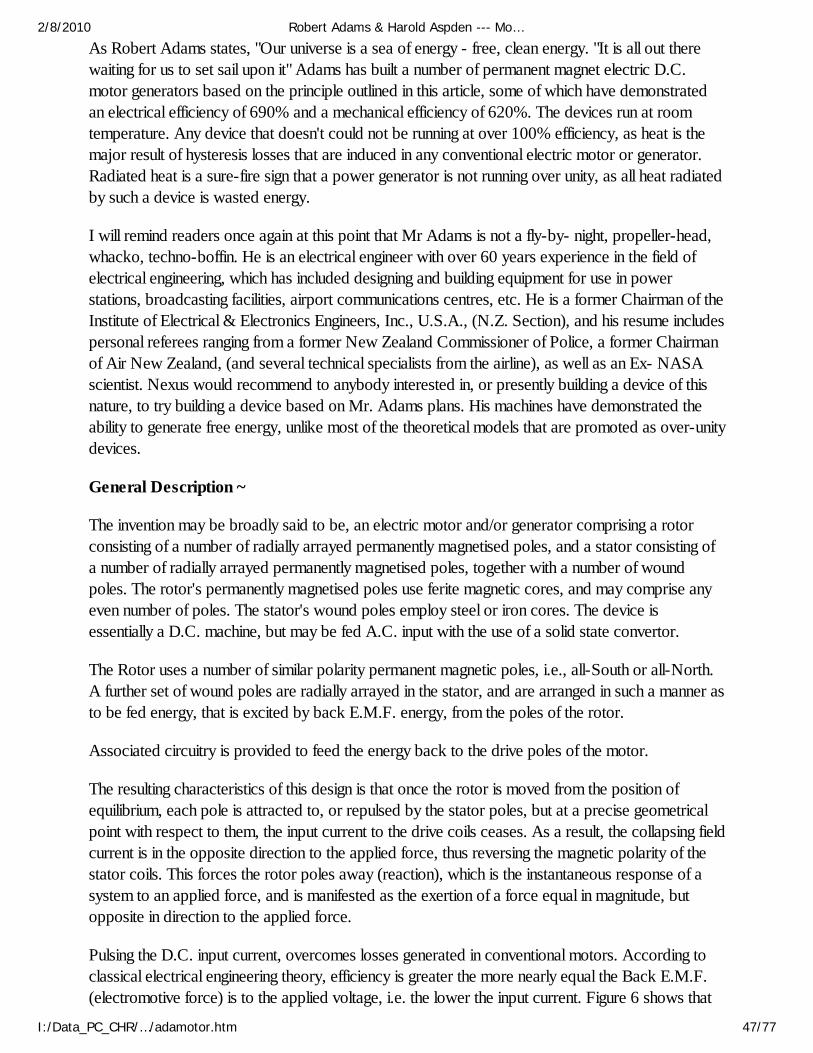
As Robert Adams states, "Our universe is a sea of energy - free, clean energy. "It is all out therewaiting for us to set sail upon it" Adams has built a number of permanent magnet electric D.C.motor generators based on the principle outlined in this article, some of which have demonstratedan electrical efficiency of 690% and a mechanical efficiency of 620%. The devices run at roomtemperature. Any device that doesn't could not be running at over 100% efficiency, as heat is themajor result of hysteresis losses that are induced in any conventional electric motor or generator.Radiated heat is a sure-fire sign that a power generator is not running over unity, as all heat radiatedby such a device is wasted energy.
I will remind readers once again at this point that Mr Adams is not a fly-by- night, propeller-head,whacko, techno-boffin. He is an electrical engineer with over 60 years experience in the field ofelectrical engineering, which has included designing and building equipment for use in powerstations, broadcasting facilities, airport communications centres, etc. He is a former Chairman of theInstitute of Electrical & Electronics Engineers, Inc., U.S.A., (N.Z. Section), and his resume includespersonal referees ranging from a former New Zealand Commissioner of Police, a former Chairmanof Air New Zealand, (and several technical specialists from the airline), as well as an Ex- NASAscientist. Nexus would recommend to anybody interested in, or presently building a device of thisnature, to try building a device based on Mr. Adams plans. His machines have demonstrated theability to generate free energy, unlike most of the theoretical models that are promoted as over-unitydevices.
General Description ~
The invention may be broadly said to be, an electric motor and/or generator comprising a rotorconsisting of a number of radially arrayed permanently magnetised poles, and a stator consisting ofa number of radially arrayed permanently magnetised poles, together with a number of woundpoles. The rotor's permanently magnetised poles use ferite magnetic cores, and may comprise anyeven number of poles. The stator's wound poles employ steel or iron cores. The device isessentially a D.C. machine, but may be fed A.C. input with the use of a solid state convertor.
The Rotor uses a number of similar polarity permanent magnetic poles, i.e., all-South or all-North.A further set of wound poles are radially arrayed in the stator, and are arranged in such a manner asto be fed energy, that is excited by back E.M.F. energy, from the poles of the rotor.
Associated circuitry is provided to feed the energy back to the drive poles of the motor.
The resulting characteristics of this design is that once the rotor is moved from the position ofequilibrium, each pole is attracted to, or repulsed by the stator poles, but at a precise geometricalpoint with respect to them, the input current to the drive coils ceases. As a result, the collapsing fieldcurrent is in the opposite direction to the applied force, thus reversing the magnetic polarity of thestator coils. This forces the rotor poles away (reaction), which is the instantaneous response of asystem to an applied force, and is manifested as the exertion of a force equal in magnitude, butopposite in direction to the applied force.
Pulsing the D.C. input current, overcomes losses generated in conventional motors. According toclassical electrical engineering theory, efficiency is greater the more nearly equal the Back E.M.F.(electromotive force) is to the applied voltage, i.e. the lower the input current. Figure 6 shows that
2/8/2010 Robert Adams & Harold Aspden --- Mo…
I:/Data_PC_CHR/…/adamotor.htm 47/77
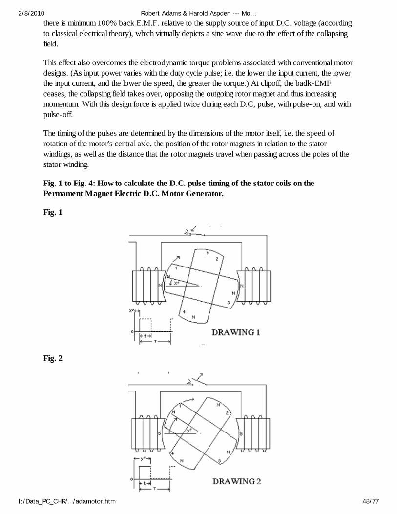
there is minimum 100% back E.M.F. relative to the supply source of input D.C. voltage (accordingto classical electrical theory), which virtually depicts a sine wave due to the effect of the collapsingfield.
This effect also overcomes the electrodynamic torque problems associated with conventional motordesigns. (As input power varies with the duty cycle pulse; i.e. the lower the input current, the lowerthe input current, and the lower the speed, the greater the torque.) At clipoff, the badk-EMFceases, the collapsing field takes over, opposing the outgoing rotor magnet and thus increasingmomentum. With this design force is applied twice during each D.C, pulse, with pulse-on, and withpulse-off.
The timing of the pulses are determined by the dimensions of the motor itself, i.e. the speed ofrotation of the motor's central axle, the position of the rotor magnets in relation to the statorwindings, as well as the distance that the rotor magnets travel when passing across the poles of thestator winding.
Fig. 1 to Fig. 4: How to calculate the D.C. pulse timing of the stator coils on thePermament Magnet Electric D.C. Motor Generator.
Fig. 1
Fig. 2
2/8/2010 Robert Adams & Harold Aspden --- Mo…
I:/Data_PC_CHR/…/adamotor.htm 48/77
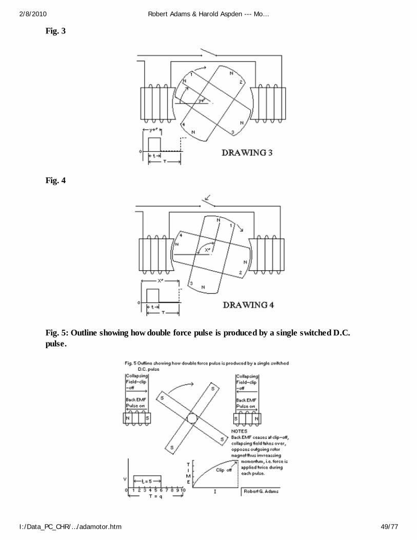
Fig. 3
Fig. 4
Fig. 5: Outline showing how double force pulse is produced by a single switched D.C.pulse.
2/8/2010 Robert Adams & Harold Aspden --- Mo…
I:/Data_PC_CHR/…/adamotor.htm 49/77
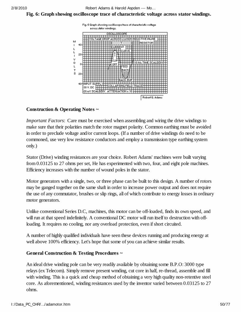
Fig. 6: Graph showing oscilloscope trace of characteristic voltage across stator windings.
Construction & Operating Notes ~
Important Factors: Care must be exercised when assembling and wiring the drive windings tomake sure that their polarities match the rotor magnet polarity. Common earthing must be avoidedin order to preclude voltage and/or current loops. (If a number of drive windings do need to becommoned, use very low resistance conductors and employ a transmission type earthing systemonly.)
Stator (Drive) winding resistances are your choice. Robert Adams' machines were built varyingfrom 0.03125 to 27 ohms per set, He has experimented with two, four, and eight pole machines.Efficiency increases with the number of wound poles in the stator.
Motor generators with a single, two, or three phase can be built to this design. A number of rotorsmay be ganged together on the same shaft in order to increase power output and does not requirethe use of any commutator, brushes or slip rings, all of which contribute to energy losses in ordinarymotor generators.
Unlike conventional Series D.C, machines, this motor can be off-loaded, finds its own speed, andwill run at that speed indefinitely. A conventional DC motor will run itself to destruction with off-loading. It requires no cooling, nor any overload protection, even if short circuited.
A number of highly qualified individuals have seen these devices running and producing energy atwell above 100% efficiency. Let's hope that some of you can achieve similar results.
General Construction & Testing Procedures ~
An ideal drive winding pole can be very readily available by obtaining some B.P.O: 3000 typerelays (ex Telecom). Simply remove present wmding, cut core in half, re-thread, assemble and fillwith winding. This is a quick and cheap method of obtaining a very high quality non-retentive steelcore. As aforementioned, winding resistances used by the inventor varied between 0.03125 to 27ohms.
2/8/2010 Robert Adams & Harold Aspden --- Mo…
I:/Data_PC_CHR/…/adamotor.htm 50/77
The above windings described are ample to drive prototypes even in a 180' application. You willfind speeds up to 2500 rpm with only two of these windings 180' apart - no problem.
For A,C. Output Coil Windings and Core: Ideal cores can be built cheaply and quickly bydismantling a spare power or audio transformer and utilising the 'I' section laminations, obtainwinding former to fit same and it is ready for winding. Turns and gauge will depend on what voltageand current you choose. Remember, at this stage, you should only be building a demonstrationmodel, so to speak.
After a few changes, corrections and/or general modifications you will be ready to put a mechanicaland/or electrical load on the machine. For an electrical load it is suggested you firstly wire up a bankof 6 - 12 LEDs. If everything is go, then switch over to torch lamps: Later on with a bigger machine- car lamps, or maybe household lamps and a mechanical load simultaneously.
For Efficiency Testing: Milliamp meters are useless for this machine - do not use for testing. Useonly high quality digital true RMS meters, with input power, for high accuracy, use only a highquality electronic wattmeter: These instruments measure extremely accurately any wave-shape. Agood twin-beam oscilloscope is a must: So too a high quality electronic temperature-measuringinstrument with appropriate probe.
Drill dead centre of one or both cores, as per drawing. Probe be must be good fit. If, after one hourof running on load and temperatare is around 40 degrees, that will indicate things are most likelyworking correctly.
Don't forget your ambient in Australia will be considerably higher than ours. Read the inventor'srotary and solid state efficiency measurarnent data sheet.
Rotor-stator air gap is not critical, but the closer the better.
As stated elsewhere, the stator pole faces, if desired, may be reduced to 25% of the rotor pole facearea, hence large drive windings and high drive current is not required.
With care to detail, correct mathematical calculations and high quality instrumentation correctlyutilised, incredible results can be expected. Study data submitted shows those results have beenattained on several machines.
Temperature of conventional machines internally reach boiling point after fifteen minutes running.Check the Adams Mctor Generator after running on full load for 48 hours, or after fifteen minutes ifyou prefer not to wait that long. You will be very pleasantly surprised - I refer to maximum loadingconditions, not free running.
Mechanical Loading Test: A high quality strain measuring instrument must be used in the universal"pony brake' method of mechanical load testing.
RPM tests must also be obtained with a high quality tachometer and/or oscilloscope reading anduse the universal equation to calculate mechanical machine efficiency.
Note: Very Important Factor --- As you increase duty cycle, current input will increase and
2/8/2010 Robert Adams & Harold Aspden --- Mo…
I:/Data_PC_CHR/…/adamotor.htm 51/77

efficiency will decrease. From random test sheet results I have chosen it is very clear what to expectupon increasing duty cycle.
Note: The Adams Motor Generator is so efficient, so simple and consequently it's construction issuch that it surpasses overwhelmingly anything before it, thus lending itself admirably to massproduction.
One of a number of unique features of the Adams Machine is the fact that the same rotor poles areutilised simultaneously for driving the machine and generating output energy.
Construction Equation - Adams Motor Generator (20-12-76): It was found, after considerabledevelopment work, that maximum electro- magnetic effect produced in the stalloy stackedgenerating pole windings occurred when the dimension of the mating end of the stacks were fourtimes greater in area than the rotor magnet's pole area. Hence the overall design of the machineincorporates this derived ratio of one to four. (The Adams Equation, as applies only to the AdamsMachine).
Feedback (20-12-1976): The feedback, produced by the output generating coil, produces apolarity reversal normally resulting in large eddy current losses in conventional machines, but, in theAdams Machine, it is hamessed to develop further additional torque to the magnetic rotor. Thelarger the output generating coils the greater the torque delivered to the rotor.
Power Factor (1-7-1976): There is no power factor loss because the Adams Machine runs in acondition of resonance. Therefore, the Power Factor Loss is zero.
Nexus Magazine (June-July 1995)
The Adams Super-Power Multi-Polar Magnet
I have for many years theorised the existence of four poles interacting in any magnet. There is littledoubt that two poles dominate from what is observed, and taught, in classical texts.
However, since my discovery of engineering magnets into forming four poles - and, in so doing,quadrupling the energy - surely some light has been shed on the theory of the existence of fourpoles. Bruce Cathie and I will investigate this further when time permits.
A rectangular or cube magnet, when engineered into the Adams technology, becomes a unitconsisting of four twin poles, each face containing a north and a south pole, separated by a zerovortex in the centre of each of the four twin poles, and all displaying similar energies.
Ironically, but not unexpectedly, this super twin-pole magnet is a very valuable adjunct to furtheradvancement of the Adams Motor technology. The energy found on the edges of each of the fourfaces is very high-25 per cent of the total energy of the full face.
The present lab magnets are approximately three-quarters-of-an-inch cube. The edge of any face
2/8/2010 Robert Adams & Harold Aspden --- Mo…
I:/Data_PC_CHR/…/adamotor.htm 52/77
will hold a five-kilogram steel or iron block in mid-air. When the full face of the magnet is attachedto metal, a force of beyond 20 kg is required to remove it. In my presentation to the NEXUSConference, I advised tests would be carried out this month to determine the strain required toremove the magnet.
The dice-sized magnet was attached to a steel plate on a ceiling rafter and, with the aid of a chain, a15-kilogram block was first attached to it; then a 4.7-kg block added on with a nylon rope; thenanother 200-gram block was attached; then, a fourth 2W-gram block. The magnet still hanging fast,a 100-gram block was added; then...wait for it...CRASH to the floor. The magnet was stillattached to its anchor on the roof-rafter!
A magnet, approximately three-quarters-of-an-inch cube, weighing only 60 grams, capable ofholding a weight of beyond 20 kilograms in mid-air, 333.333 times its own weight? Will this at lasthave something of an effect on the closed ignorant minds of conventional science?
The way now must surely be clear that space/gravity energy via electromagnetic forces ofpermanent magnets is not impossible nor difficult to harness. The space/gravity energies are clean,non-exhaustible and free. The Adams technology has proved this and leaves no grounds fordispute.
Einstein's sacrosanct theories of relativity, and the laws of thermodynamics, are the mostremarkable and inexplicable aberrations ever recorded in scientific history. These draconian falseteachings have been instrumental in impeding tbe process of science towards free, clean energy.
Classical Theory & Adams Technology ~
The classical theory of magnetism from the textbooks attiibutes the phenomenon to the motion ofelectrons within the atoms of molecules. There is evidence that the orbital electrons in an atom notonly revolve about the nucleus of the atom, but also each individual electron spins about an axisthrougb its centre. Isis believed that in highly magnetic materials, each atom has many moreelectrons spinning in one direction than in another. In the submicroscopic region, i.e., the "domain", many of these atoms with electron spin in onedirection create a magnetic field which effectively supplements the field engendered by the revolvingelectrons. Each domain thus becomes a tiny magnet. When the domains are in random state, thesubstance as a whole is not a magnet. The application of external magnetic field will reorient thedomains and produce a magnet in the way described above.
When the application of an external magnetic force has been applied and all the domains have beenaligned, the condition of MAGNETIC SATURATION has been reached, and any further increasein strength of the external force field will not increase the magnetisation of the iron any further. Withthe advent of the Adams Permanent Magnet Technology, is it not further evidence that conventionaltext teachings have reached the stage when they should be rewritten?
From the observations of certain lab experiments with ball-bearings, it is the opinion of thediscoverer that the electrons circulate in conjugate pairs and have a spin opposite to that of rotation,and that the spin is four times greater than that of the orbital rotation. I note also that conventionaltexts prefer not to state direction of spin, nor velocity relative to orbital motion.
2/8/2010 Robert Adams & Harold Aspden --- Mo…
I:/Data_PC_CHR/…/adamotor.htm 53/77
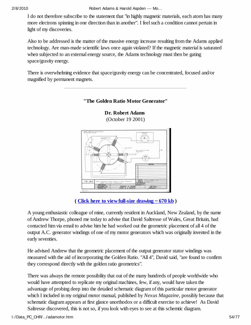
I do not therefore subscribe to the statement that "in highly magnetic materials, each atom has manymore electrons spinning in one direction than in another". I feel such a condition cannot pertain inlight of my discoveries.
Also to be addressed is the matter of the massive energy increase resulting from the Adams appliedtechnology. Are man-made scientific laws once again violated? If the magnetic material is saturatedwhen subjected to an external energy source, the Adams technology must then be gatingspace/gravity energy.
There is overwhelming evidence that space/gravity energy can be concentrated, focused and/ormagnified by permanent magnets.
"The Golden Ratio Motor Generator"
Dr. Robert Adams (October 19 2001)
( Click here to view full-size drawing ~ 670 kb )
A young enthusiastic colleague of mine, currently resident in Auckland, New Zealand, by the nameof Andrew Thorpe, phoned me today to advise that David Saltresse of Wales, Great Britain, hadcontacted him via email to advise him he had worked out the geometric placement of all 4 of theoutput A.C. generator windings of one of my motor generators which was originally invented in theearly seventies.
He advised Andrew that the geometric placement of the output generator stator windings wasmeasured with the aid of incorporating the Golden Ratio. "All 4", David said, "are found to confirmthey correspond directly with the golden ratio geometrics".
There was always the remote possibility that out of the many hundreds of people worldwide whowould have attempted to replicate my original machines, few, if any, would have taken theadvantage of probing deep into the detailed schematic diagram of this particular motor generatorwhich I included in my original motor manual, published by Nexus Magazine, possibly because thatschematic diagram appears at first glance unorthodox or a difficult exercise to achieve! As DavidSaltresse discovered, this is not so, if you look with eyes to see at this schemtic diagram.
2/8/2010 Robert Adams & Harold Aspden --- Mo…
I:/Data_PC_CHR/…/adamotor.htm 54/77
Congratulations go to David Saltresse of Wales.
Now, further secrets are revealed in which I can advise readers that I apply the so named "SacredGeometry" of the golden ratio in conjunction with a very important natural occuring constant ofnature. I also apply this same equation to resistance measurements, load resistances, voltage,geometrics of magnets, rotor and stator dimensions. This equation also applies to the mass andplacement of the addition of certain unusual material used in the construction of this awesome heatgenerating rotor system. This is a unique system in that it is an implosive and totally reverseengineered mahcine which operates in the real realm of unity. The power manifested over time is"infinite" and therefore immeasurable. A reminder here to those unaccustomed to the understandingof the condition known as Infinite Energy, irrespective of any measurement of input energy lossesand input power, there is no known value / measurement of infinite energy output power. Becauseof its infinity it simply cannot be measured!
Adams Special Release of Information for Those Experimenting with My Motor-Generator Technologies
From a number of reports I am in receipt of I find experimenters are using powerful rare earthmagnets in their machines. This is in order only if you are incorporating the correct operatingparameters, i.e., first of all upon handling the magnets, it is very quickly recognised that they arevery powerful for such small dimensions. Does it not strike you then that since they display suchobvious considerable power, is it then not logical that considerable impulsing power is going to berequired to drive the machine once the magnets are installed in the device.
The cardinal mistake being made here is that most of these experimenters are concerned about I²Rlosses! If you are seeking high/super performance with these powerful magnets, then discard allconcerns in relation to Ohms Law, for in the Adams technologies Ohms Law becomes a non-entity. Instead of expecting results of a high order with stators of very low resistance, such as under10ohms, increase the total series electrical resistance instead to 72ohms and instead of expectingspectacular results using these powerful magnets with only 12 - 24 volts, increase the voltage to aminimum of 120v. Upon having done this you must give attention to other important factors, i.e.,stator to magnet air gap should be 1 - 1.25mm, impulse duty cycle should be 0.25 - 0.35, "mosfet"gate signal impulse 10 - 20v of good clean stable D.C. Upon initial experimental tests, I havealways used batteries. Reduce the face area of stators to 75% of the magnet face.
Now having said all this, choose your own method of signal switching, whether it be photo, Hall,magnetic, reed or mechanical, etc.
Upon fine tuning, and now having reached greatly increased power and performance, 'DOUBLE'the power supply voltage to 240v and you will have a machine in the "kilowatt" range, the excitingstage of your progress. There are a number of various methods of harnessing considerable aethericenergy from these machines. In this respect I strongly urge you to study Tesla radiant energy.
Recommended Reading:
"Physics Without Einstein" by Dr. Harold Aspden, United Kingdom.
2/8/2010 Robert Adams & Harold Aspden --- Mo…
I:/Data_PC_CHR/…/adamotor.htm 55/77
"Thermodynamics and Free Energy" by Dr. Peter A. Lindemann, USA. "Secrets of Cold War Technology" by Gerry Vassilatos, USA. "The Cosmic Pulse of Life" by Trevor James Constable, Hawaii. "Nicola Tesla" by Leland Anderson, USA.
Miscellaneous Notes by Dr Adams
Construction Equation - Adams Motor Generator (20-12-1976) ~
It was found, after considerable development work, that maximum electromagnetic effect producedin the stalloy [sic] stacked generating pole windings occurred when the dimension of the mating endof the stacks were four times greater in area than the rotor magnet's pole area. Hence the overalldesign of the machine incorporates this derived ratio of one to four. (The Adams Equation, asapplies only to the Adams Machine).
Feedback (20-12-1976) ~
The feedback, produced by the output generating coil, produces a polarity reversal normallyresulting in large eddy current losses in conventional machines, but, in the Adams Machine, it isharnessed to develop further additional torque to the magnetic rotor. The larger the output generating coils the greater the torquedelivered to the rotor.
Power Factor (1-7-1976) ~
There is no power factor loss because the Adams Machine runs in a condition of resonance.Therefore, the Power Factor Loss is zero.
The Adams Pulsed Electric Generator: The Conspiracy ~
I have for many years been waiting the opportunity to make a start on writing about my life as anelectrical engineer and inventor, but have been reluctant to do so because of the possible reactionfrom one formidable individual who was instrumental in causing me untold frustration, ridicule,anxiety, financial problems, and health decline.
With the passing of Rob Muldoon, I now feel more deposed to exposing what he and his regimesubjected me to, and the possible subsequent valuable loss to our country as a result. I personallyhad a meeting with Muldoon and others at his home office in Tamaki regarding my invention.
The result of the meeting was that he recommended me to the Inventions Development Authority. Inall good faith I duly contacted the inventions development authority and that folks was the beginningof the saga which was destined to follow.
The Inventions Development Authority passed me along to DSIR, who at the time were franticallyworking on their own energy systems, and assisting Government with various 'Think Big' projects.
Time rolled on, and DSIR monkeyed me around for several months; there were, as always, excuses
2/8/2010 Robert Adams & Harold Aspden --- Mo…
I:/Data_PC_CHR/…/adamotor.htm 56/77
for not proceeding with completion of their strange testing apparatus to test my machine.
In the meantime, Rob Muldoon appoints himself Minister in Charge of SIS, the department withworld-wide connections to the CIA, ASIO, FBI and Interpol!
I had meanwhile, designed a bigger proving machine and had placed orders overseas for magnetsand devices for pulsing equipment. Time went by, well beyond expected delivery dates, with nosign of the devices, nor any correspondence pertaining to my orders to any of the electricalcompanies.
I lodged person-to-person calls to the people who originally signed the confirming correspondenceto me, to be told that "that person in no longer with us and we cannot help you any more."
Muldoon had by now, committed the whole country to the New Plymouth Power Station, HuntlyPower Station, Marsden Oil Refinery, etc etc. The Government signalled its intentions that is was inno way going to let a little outsider like me come into the act with a revolutionary machine capableof countering the so-called energy crisis.
Muldoon at this stage, had me well taped up so to speak, My phone, I was informed, was tapped,my mail was intercepted and I was kept under observation.
I held a number of meetings with the Chief Post Office Investigating Officer regarding the matter ofmail disappearance and interception, with the same negative and unsatisfactory answers and resultsas from other Government departments. After the lapse of several months, the machine was finallyevaluated by DSIR.
I must mention here an interesting fact regarding the evaluation of my machine by the DSIR. Ithappens that a certain electrical engineer that I was involved with, who incidentally, also evaluatedmy machine, informed me that the person designated the role of evaluating my machine in DSIR,was in fact a mechanical engineer with no background, knowledge, nor qualifications of anydescription pertaining to electrical or electronic engineering, and further that the Auckland Divisiondid not posses a member on the staff qualified to undertake such a project. This person none-the-less did do the evaluation and indeed signed the test results.
(You may well wonder how did this independent electrical engineer have such inside information onthe DSIR? Well, it so happened that he himself had been their one and only electrical engineer in theAuckland Division, and I might add, a specialist on electrical motors too.)
That an unqualified person was assigned the task of evaluating the possibilities of a revolutionarymotor is further evidence to me of conspiracy.
DSIR Evaluation - 5.8% efficiency ~ Lucas Industries Evaluation - 100% efficiency!
Other independent eminent engineers' findings, including those of the ex-electrical engineer fromDSIR varied from 96.93% to 100% efficiency!
At this stage, I had unwittingly invited the then chief departmental district electrical engineer to be
2/8/2010 Robert Adams & Harold Aspden --- Mo…
I:/Data_PC_CHR/…/adamotor.htm 57/77
present at my laboratory to witness the phenomenon of one particular model displaying identicalinput and output wave forms on a twin beam oscilloscope with the machine windings running atambient temperature, a condition which cannot be denied as proof of 100% efficiency, without anyfurther tests being required.
He conceded there was no doubt whatever what he was witnessing was real, but like all academicswho stick to their ivory tower scientific establishment beliefs, he said it could not be done.
Upon reading certain of my writings, it will be found that at one time in earlier years, I disbelieved inany kind of conspiracy regarding inventions pertaining to energy efficiency, and certaincommunication installations. I must now say, having unwittingly got myself into the web of the insidious conspiracy, throughtreading the path of an inventor in the field of free energy, that I now know from personalexperience the pitfalls, stone walls, and blatant obstacles and barriers designed to hamper andsilence inventors with such devices as energy efficient machines.
I decided to investigate the fate of a number of other excellent energy- efficient inventions, andlearned that too many good inventions were never heard of again. Inventors themselves wereturning into hermits, meeting with unexplained accidents, even totally disappearing. In many casestheir laboratories were searched and ransacked, equipment confiscated and/or destroyed, and evenattempts made on their lives. Others are frequently bought off in return for silence.
The conspirators, who are also the cartel operators are determined to continue to make mankinduse fossil fuel for all possible energy requirements and will go to any lengths to achieve just that.
I have since superseded the above machine and have built and proven two different types of self-sustaining motor generators with efficiency ratings well beyond unity.
Adams Breaks the Gravity Barrier ~
Inventor Robert Adams appears to have broken the gravity barrier, with his advanced AdamsElectric Motor Generator operating in a high state of resonance and apparently tapping gravitationalenergy.
"During the later months of 1992, I derived what I considered to be an equation for possibly theultimate in rotary motor generator design. The purpose of this exercise, was to ascertain whetherfurther unconventional design features of the machine parameters, using this equation, provedcertain theories which I had previously discussed with Mr. Bruce Cathie, an internationallyrecognized New Zealand researcher in this field. (Cathie is the 'father' of grid harmonics)
Upon applying the 'equation' to the machine parameters and testing it, there was no doubt themachine was running in a higher state of resonance than previously obtained.
It had been arranged beforehand between myself and Mr. Cathie that, should the results of this testbe of some substance, Mr. Cathie would travel from Auckland to Whakatane specifically to checkthe machine parameters with his 'harmonic equations'. These results confirmed the theory which wehad previously discussed and planned to implement.
2/8/2010 Robert Adams & Harold Aspden --- Mo…
I:/Data_PC_CHR/…/adamotor.htm 58/77
The results of these first trial tests have been SUPERCEDED, with the new figures obtained beingfound beyond anything that is known of in the present- day field of free energy research. There isevery possibility that these latest figures, also, will be surpassed in the near future.
The equations and how they are applied are hidden within certain parameters, and, to this end, itcould be said that to reach the ultimate in rotary overunity devices is not possible without thecorrect application to all parameters of the machine using the 'Adams Pulse Method' and the Adams-Cathie equations.
The above methods and results give us a valuable lead in the realm of solid-state gravitationalenergy research. The equations and methods of application in design procedures, however, remain,at this stage, secret. The efficiency figures possible from the device are such that they simply cannotbe published.
I wish readers to refer further to the following discussions on Wilhelm Muller and Dr. RolfSchaffranke, the general content of which relates to my discovery of the mysteries of magnetismsome twenty-four years ago."
The Adams Pulsed Electric Motor Generator: On Wilhelm Muller ~
Reference to an article authored by Tom Valentine, California based freelance journalist, in regardto claims by Wilhelm Muller and his magnet manufacturers.
I must take Muller and his magnet manufacturers to task on their statement that "magnets can do atremendous amount of work" - this is not so. In an over-unity rotary machine, the magnets are'assisting' to run the machine, but they are not generating the extra energy beyond the reaching of100% efficiency. The magnets are not doing actual work, as such, beyond that point.
It is likely Muller's machine is operating, according to the efficiency figure Muller quoted,somewhere on the near lower end of a positive resonance curve. From the generally knowninformation on his device, this would be the likely area in which it is operating. If this is so, then thechances of greater efficiency are slim, particularly on account of it appearing to be operating in apositive mode. For the rotor magnets to operate as a gate to harness gravitational energy beyondunity, it must be in a negatively resonant mode and not operating in a closed magnetic circuit system.
Bruce Cathie and I spent an entire day together in January 1993 going over his harmonic equationsin regard to my advanced machine, and confirmed that it was running in an advanced state ofresonance, harnessing gravitational energy and demonstrating evidence of the magnets forming a'gate' to harness one half- cycle of the gravitational pulse, but doing no actual work over and above the 100%.
In regard to another claim by Muller that he had to use powerful neodymium magnets, this also iscontrary to our findings. It matters not whether you use standard off-the-shelf 'alnico' magnets orpowerful magnets, the results are no different. It is not necessary to use powerful magnets to proveif a machine can be constructed with over unity capability. This fact has been shown repeatedly withthe Adams machines, using small and weak magnets.
The inference also that Nikola Tesla might have required today's advanced magnetic materials to
2/8/2010 Robert Adams & Harold Aspden --- Mo…
I:/Data_PC_CHR/…/adamotor.htm 59/77
achieve over unity results, is also totally wrong. The only difference between using ordinary magnetslike 'alnico' and, for instance, 'samarium cobalt', is that you get greater energy output from thestronger magnets by way of their ability to detect and amplify this energy on a greater scale; and,therefore, upon utilizing the Adams pulsing system, you can have a device using any ordinarymagnets capable of not only 100% efficiency, but also of being tuned into operating as a gate indetecting and delivering gravitational energy.
As for the establishment's texts stating that "magnets do NO real work", the establishment, for once,is correct. It is, however, interesting to note that this is a very 'convenient' fact for the establishmentto expound upon - there could be an underlying inference here that magnets are useless formachines designed to achieve beyond unity results.
Permanent magnets and their place in science today need to be more fully understood."
On Dr. Rolf Schaffranke ~
"Reference to an article written by Dr. Schaffranke in THE MANUAL OF FREE ENERGYDEVICES AND SYSTEMS, VOLUME TWO, published by D.A. Kelly, in which on page 7,paragraphs 7 and 12, Dr. Schaffranke erroneously maintains it is NECESSARY to use supermagnets to tap gravitational energy.
I found that my original 1970 open magnetic circuit motor generator is superior to my 1976 closedmagnetic circuit model in regard to the results of obtaining and maintaining a correct harmonicvacuum oscillation and so tapping gravitational energy during one half-cycle of the gravitationalpulse wave.
People who make such claims regarding the use of super magnets, obviously have little or noexperience in the realms of rotary free-energy devices using permanent magnets. Over twenty yearsago, I proved that even tiny weak magnets bought off the shelf and incorporated into my machinesyielded efficiency into the hundreds of per cent over unity.
A permanent magnet is an entity unto itself. It is no different in any way whatsoever from itsbrothers made of different materials; it is still a permanent magnet irrespective of its gauss rating.
These claims are tantamount to saying that you can get more than 2.2 volts out of a lead acid cellsimply by increasing its ampere hour rating, or conversely, you use a ten horsepower motor to run amachine that only requires one horsepower.
I reiterate: the sooner science rejects conventionalism, the better for humankind.
If indeed magnets were doing a tremendous amount of work, they certainly would not last long inany machine. There are secrets and mysteries surrounding magnets and collapsing field energies,and only after exhaustive studies of these two phenomena in practice, do these mysteries unravelthemselves and emerge in their glory, and, correctly applied through the use of the requiredmathematics, pave the way to tapping gravitational energy in astronomical quantity.
For high-power rotary machines, however, super magnets are the obvious choice, for reasons ofhigher power capabilities, reduced weight and volume. When installed in an 'Adams' machine, these
2/8/2010 Robert Adams & Harold Aspden --- Mo…
I:/Data_PC_CHR/…/adamotor.htm 60/77

super magnets enable the opening up of clearances between rotor and stator without appreciableloss due to the high overall efficiency of this machine.
If indeed it were possible to induce magnets to do a tremendous amount of work, as claimed by theaforementioned people, then I claim that the magnets must first have very substantial energyimparted to them to undertake the task ahead. Secondly, when reaching this 'tremendous' state,they would start heating up and continue to do so until they reach the point whereby their magnetismwould begin disintegrating, and continue to do so until the machine would eventually come to a halt,unable to start again.
There are a lot of people out there striving for the ultimate in rotary electrical machines. They allhave my personal blessings for their endeavors, but may I hasten to add for those who make suchclaims, that they exhibit a lack of experience and knowledge of the capabilities of permanent magnets in rotaryelectrical machines.
But don't be disappointed, readers, as I assure you that permanent magnets are indeed the answerto free energy. Correctly adapted to a rotary machine they are the 'gateway' to harnessinggravitational energy.
With the application of the 'Adams resonant pulse frequency equation' and the 'Cathie harmonicequations' combined with the 'Adams Pulsed EMG System', incredible energies can be very easilyand cleanly made available.
I wish to state to all readers at this particular stage, that I have only, in the past year, made thedecision to publish certain aspects from my twenty years work in the field of free energy research.
There are no doubt many other researchers who, for various reasons such as lack of finance, fear,suppression and very many other barriers, have not had even a chance to be heard. It is to behoped the day will soon arrive when all can benefit from our work."
The Adams Pulsed Electric Motor Generator (January 1993) ~
An explanation to readers on matters pertaining to hysteresis loss, eddy current loss, magnetic drag.Also some advice regarding further information required from enquiries received to date byinterested parties:
I would first like to state that it has been made clear that this machine has been proven to becapable of over-unity performance, plus the fact that it has proven itself capable of returning energyto its supply source. So we now come to the matters mentioned above.
If a machine is to run at unity or better, it must first 'overcome' those problems found in theconventional machine, which, of course, are principally those of magnetic drag, hysteresis loss andeddy currents, all of which waste energy in heat and hence require a cooling fan - with its attendantlosses as well.
As explained previously, the Adams machine runs cool in comparison to the conventional machine
2/8/2010 Robert Adams & Harold Aspden --- Mo…
I:/Data_PC_CHR/…/adamotor.htm 61/77
and does not, therefore, require a cooling fan. Now these factors surely speak for themselves. Itmust also be borne in mind by the reader that in the conventional AC or DC machine, the internalheat of windings and stators reach boiling point within fifteen minutes. The Adams machine does nothave this problem.
Given these salient factors, which in themselves are a starting point for those of you who areforward-thinking, I feel I have provided sufficient hints, information and guidance to enable thoseastute enough to realize the potentiality of the principles given, to build a machine for themselves according to their own leaningsas well as along the lines of the Adams machine.
Most of you know of the manual which has been published and distributed by NEXUS Magazine.My purpose in compiling this manual is to give those interested an insight into the principles of themysteries of my machine, and I expect those interested, patient and persevering enough to acceptthat they must work out and work with these mysteries and to, like myself, to battle to get there.Only then will true understanding and enlightenment reveal itself and true reward, however slowly,be theirs.
Notwithstanding these statements however, I submit here a few further valuable recommendationsfor readers, and as time progresses, and as time permits, some further such tidbits of informationwill be drip-fed through NEXUS as a form of encouragement to all concerned.
I would like to inform readers at this point in time that, because of the steady flow of response Ihave had since publication in NEXUS, by enthusiasts, interested parties and investors alike, it is nolonger possible to address enquiries of the nature of those above individually, other than on aconsultancy basis. Although I will continue to contribute certain articles to NEXUS as long as I amable, and will continue to personally reply to all mail, I ask readers to kindly understand that a gooddeal of my time is involved in consultancy already on my advanced projects, so my free time issomewhat limited. I encourage readers to keep their eyes on NEXUS as I intend to remain as loyalto them as they are to me.
Here, then, are those few further recommendations to readers. If contemplating the construction ofa proving machine, note as follows :
(1) Don't purchase expensive powerful 'neodymium' or 'samarium cobalt' magnets without firsthaving experience with cheap easy-to-get 'alnico' magnets, for if you commence with powerfulmagnets you will find yourself facing powerful problems. Using powerful magnets will not proveanything beyond what alnico will do. However, given this, if you feel you MUST choose powerfulmagnets, for whatever your reasons, take heed -great care is required in the handling of them topreclude personal injury.
(2) For a proving machine do not use less than 10 ohms each for two stators at 180 degrees apart;recommend series mode for first attempt. Don't be concerned about start windings initially and,remember, what can be achieved MICROscopically can be achieved MACROscopically and so Istrongly suggest - walk before you run.
(3) Should you experience any difficulty in designing and constructing the tapered disc contactor
2/8/2010 Robert Adams & Harold Aspden --- Mo…
I:/Data_PC_CHR/…/adamotor.htm 62/77

(machining, etc.) then use electronic switching, i.e. photo, Hall effect, or inductor effect, withswitching current transistor, etc. The machine, correctly constructed, should still deliver a minimum107% efficiency. The charging effect will, of course, be lost, and the input current to supply theelectronic switching will raise the total input quite steeply. The point to be made here is that in usingelectronic switching, in a larger machine, the degree of loss due to this use of electronic switching isnegligible.
However, for those who are seeking greater efficiency figures, it is advised to stay with the tapereddisc contactor method and build a small wattage unit, i.e. 0.25 to 1 watt. This is the area of powerrating within which you will gain quicker and better results which, in turn, will provide the necessaryexperience for designing and building a larger unit.
Once again the inventor cannot stress the importance enough, for those who wish to construct asuccessful device, to start at the bottom rung and listen to what the device is saying to you as yougo along.
Note for the Curious ~
I have received a lot of requests regarding an explanation accounting for such low temperatureoperation on full load. This one fact alone is indisputable evidence of a very high efficiency rating.
I have therefore decided to make up a set of drawings which will explain to the reader the questionsregarding hysteresis, eddy current and magnetic drag losses, as well as temperature ratings, etc.
These drawings will be accompanied with written explanations concerning the 'how'and 'why' ofcertain factors.
These drawings and their accompanying information will be available directly from the inventor atthe address given below at a cost of NZ $20.00 including postage.
Meanwhile, for further information on the 'Adams and Cathie' projects, you'll find it all in your futureissues of NEXUS."
Tim Harwood's Replication of the Adams Motor-Generator http://www.geocities.com/theadamsmotor/index.html
2/8/2010 Robert Adams & Harold Aspden --- Mo…
I:/Data_PC_CHR/…/adamotor.htm 63/77
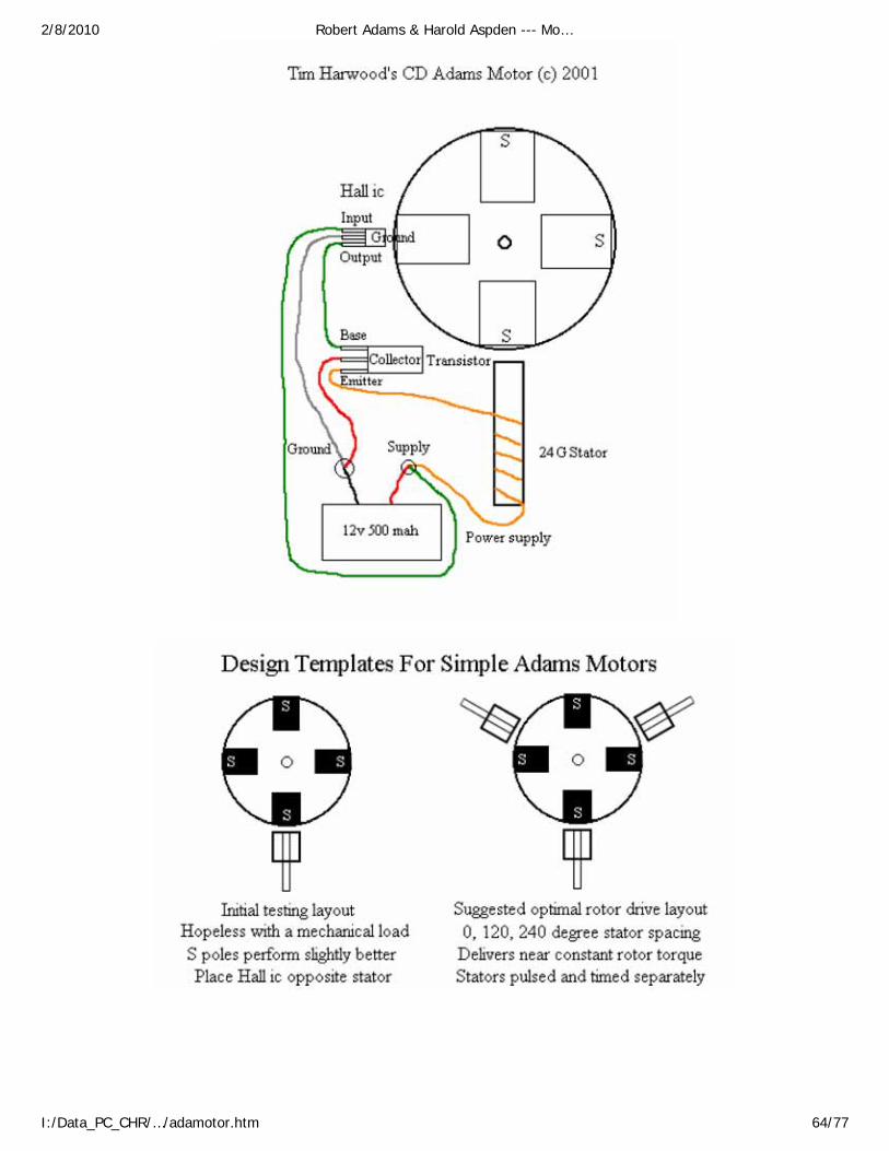
2/8/2010 Robert Adams & Harold Aspden --- Mo…
I:/Data_PC_CHR/…/adamotor.htm 64/77

2/8/2010 Robert Adams & Harold Aspden --- Mo…
I:/Data_PC_CHR/…/adamotor.htm 65/77
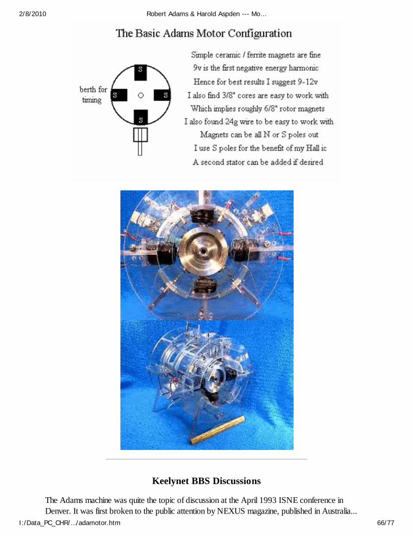
Keelynet BBS Discussions
The Adams machine was quite the topic of discussion at the April 1993 ISNE conference inDenver. It was first broken to the public attention by NEXUS magazine, published in Australia...
2/8/2010 Robert Adams & Harold Aspden --- Mo…
I:/Data_PC_CHR/…/adamotor.htm 66/77

As to the ADAMS motor, I am a bit puzzled with the comments that gravitational energy issomehow used in the machine. From my admittedly limited understanding, it simply appears that heis using the back EMF to give additional thrust and thus a much higher efficiency.
With the use of the back EMF, there would be little if any hysteresis from the "collision" of theforward EMF with the back EMF and thus the reduction in heating.
We at KeelyNet would greatly appreciate reports from anyone reading this who might choose tobuild or otherwise experiment with the principle. You may upload as a text file or send a photocopy to the Vanguard Sciences address at the top of the document. Thanks.... >>> Jerry Decker
~~~~~
Date: 12 Mar 94 20:56:00 ~ From: David Galea ~ To: all ~ Subj: AdamsMotor/Generator
Hello all: I am new to this echo area and I am not sure if anyone has discussed this topic before.
I have obtained plans for constructing a motor/generator from a Mr. Robert Adams in NewZealand and I have begun construction.
Seven people have since built this device in Australia and it seems to work fine, but no-one canexplain the effiency anomoly that occurs after about 15 minutes of running time. In the two that Ihave personally seen, the eff. rating jumps from 85% (normal) then after about 15 mins goes toaround 120%.
We have set up oscilloscopes, amp meters, volt meters, temp meters and can't account for theincrease.
We do not have access to a magnamonitor to measure the magnetic field on the rotor, but we arestill stumped.
Any ideas ? My intention is for it to be a Battery Charger.
David Galea (Melbourne Australia.)
~~~~~
There are some peculiar activities that have happened with regard to the Adams motor. As you cansee from the above email, these fellows claim to know of 7 people who have successfully replicatedthe Adams motor.
In 1993, everyone was hot for it, wanting plans and such. Within a very short period, there was abusiness arrangement made with Adams which we heard was to produce a UNITY motor to bepatented and sold in the U.K.
Sometime toward the end of 1993, the talk was that the Adams motor had not proven out, that noone had successfully duplicated the effect or there was some anomaly in the measurement method.
2/8/2010 Robert Adams & Harold Aspden --- Mo…
I:/Data_PC_CHR/…/adamotor.htm 67/77
A very bizarre turnaround if you read the above email.
At the 1994 ISNE meeting, Bill McMurtry of New Zealand gave a presentation in which he saidflat out that the Adams motor did not work. We took Bill to dinner with Tom Bearden and KenMcNeil, but did not have an opportunity to speak with him in detail because he and Ken had someitems to discuss in private.
The collaboration of Adams with Bruce Cathie had increased the over unity output to numbers thatwere so incredible as to warrant not publishing them. I read something about it being on the orderof 1:3000. At any rate, the Adams motor is far from dead if there have been independentsuccesses.
New Energy News, Vol. 4, No. 8, December 1996, pp. 1-7.
The Adams & Aspden Motor Patent by Harold Aspden
I first heard of Robert Adams and his motor at a mountain retreat west of Denver, Colorado duringthe days just before a New Energy Symposium. That was in April 1993. A benefactor [Bill &Lynda Beierwalts] interested in knowing the truths about "free energy" and its potential for solvingthe world's pollution problems had funded the expenses of the invited speakers and the preliminary"think tank" event at that retreat. My talk was about magnetism and the aether as an energy source,but our "think tank" groups each had an allocated theme. We were expected to point the finger atthe best candidate for onward investigation, from the vague information and reports we had aboutdiscoveries and claims pertaining to the new energy world.
Yes, there were several to choose from, machines involving magnets and solid-state devices such asthat devised by Hans Coler, dating from the World War II era, or the then-current activity ofSparky Sweet (now deceased). In fact, one of our team, a colleague from U.K., had visited Sweetjust prior to that Colorado meeting. However, specific information as to how to build any of thesedevices was not available, nor was there any acceptable theoretical account of their operation onwhich we could recommend action.
Fortunately, however, someone had brought with him information publicized by the NEXUSmagazine and a Manual, available from Nexus, describing a motor devised by a New Zealandernamed Robert Adams. "Over-Unity" performance was claimed and enough was disclosed as a blueprint for replication of the machine. We did not really understand how the motor could operatequite as well as Adams had indicated, but we were convinced that "over-unity" was in prospect.Accordingly, as it seemed easy to build a motor such as Adams described, our group settled for therecommendation that the Adams motor should be looked into and somehow constructed to verifyits performance.
That was how I first came to know about the Adams motor.
Collaboration with Adams ~
2/8/2010 Robert Adams & Harold Aspden --- Mo…
I:/Data_PC_CHR/…/adamotor.htm 68/77

At that time such experimental work that I had pursued on the "free energy" theme was basically onsolid-state magnetic systems and, in collaborating with a Scotsman, Scott Strachan, I had beeninvolved with the invention of a thermoelectric device which was extremely efficient at convertinglow grade heat into electricity. Undoubtedly, it defied the Second Law of Thermodynamics, but thatpoint was not stressed in those early days. That invention had proved problematic because thedevices built worked for a while by repeated operation for half an hour or so at a time, day afterday, for several months, but then came the inevitable progressive weakening in conversionefficiency, ending with a defunct piece of equipment.
The story on that is told between pages 124 and 128 of Jeane Manning's excellent book, TheComing Energy Revolution - The Search for Free Energy, ISBN 0-89529-713-2 published in1996 by Avery Publishing Group, Garden City Park, New York.
I was distracted from that thermoelectric venture when I took a more practical interest in themagnetic reluctance motor, inspired by what we had heard about Robert Adams. I was to bedistracted again towards the end of 1995 when the Correa "Abnormal Pulsed Glow Discharge"invention came to my attention, with its 5:1 over-unity feature clearly demonstrated. And now, asyear-end 1996 approaches, I am destined to be distracted again, this time by having discoveredmyself why those thermoelectric devices mentioned above had failed. The remedy is easy as theproblem does not involve deterioration. It is as if a bistable system has flipped to its off-state andjust needs to be flipped back into its on-state, provided, that is, one knows what to flip!
Now, to come to the point about my collaboration with Robert Adams, I am writing these wordson October 28th, 1996 and in a week from now the granted patent I have procured jointly withRobert Adams will become available from the British Patent Office in its issued form. It is PatentNo. GB 2,282,708. I plan, in these pages, to introduce my own motor research and relate it to thatpatent and explain my connection with Adams.
I am also mindful that Adams, now recognized by an honorary doctorate from the OpenInternational University of Sri Lanka, to become Dr. Robert George Adams, has recently publishedan addendum to the Adams Motor Manual entitled: "The Revelation of the Century" and hasincluded in that work some of my written contributions.
The immediate focus of my attention, however, is a rather critical letter communication authored byMichio Kaku and sent to a programme producer of a radio station based in New York. It wasdated May 20th 1996, but it is only now that I have become aware of this communication fromRobert Adams' new book.
Adams need not have included Kaku's letter in his book, but he did and I commend him for it.Apart from saying that Robert Adams was either the next Einstein and Newton rolled into one or acrackpot, he made these two comments:
"Apparently, he (Adams) wants to extract energy from the aether by using rotating magnets, therebyviolating the first law of thermodynamics (conservation of mass and energy). This is an ancient idea,going back centuries and was most popular in the 1880s, but was disproved by the Michelson-Morley experiment and Einstein's relativity theory. Aether, which was supposed to be a magical
2/8/2010 Robert Adams & Harold Aspden --- Mo…
I:/Data_PC_CHR/…/adamotor.htm 69/77
substance which pervaded the universe, has never been measured in our laboratories."
"The proof is in the pudding. He (Adams) has to show a blueprint of his machines, show that they infact generate energy, and show with a few equations how his theory works. Lacking a blueprint, amathematical theory, and, say, video tapes of his motors generating energy from nothing, I cannotsay with 100% certainty that he is wrong. (Only 99.99%)"
Now, having just had an "over-unity" motor patent granted in which I share inventorship withAdams, I will assume that those Kaku remarks are addressed also in my direction and replyaccordingly, point by point.
Firstly, as a educational exercise, the extraction of energy from the aether does not violate the firstlaw of thermodynamics. By definition or simple semantics, if you extract energy from something andmove it from that something, A, into something else, B, the energy remains conserved overall. Thefirst law of thermodynamics dates from before the time when the transmutation of mass and energywas recognized as the stellar power source by Sir James Jeans (1904). A critic might say, however,as Jeans himself did in his 1928 book EOS, that Isaac Newton knew of photosynthesis by whichradiant energy transmitted through space is captured by plants and convened into matter, whichstores energy by creating a combustible product. The transmutability of energy and mass was notdiscovered, nor was it first suggested, by Einstein. He was too late.
Secondly, the existence of the aether was not disproved by Einstein. Indeed, Einstein has notproved anything, nor has he disproved anything. One simply cannot flaunt Einstein's theory aroundas a reason for rejecting the prospect of an "over-unity" motor. On the contrary, ask yourself whythere are plans to test Einstein's theory at a cost of $500,000,000 dollars by launching GravityProbe B in 1999. If Einstein's theory is right, why are there any doubts warranting expenditure onthat scale?
Thirdly, Kaku says the aether has never been measured in our laboratories and that its existencewas disproved by the Michelson-Morley Experiment. The fact is that Michelson did not performthe experiment to test or refute the existence of the aether. He lived another 44 years afterperforming that experiment and believed in the aether to his dying day. He was trying to sense theEarth's motion through the aether, but, since standing waves developed by mirror reflection had notbeen discovered when the experiment was planned, he had not allowed for that to affect the resultobserved. In fact, the aether energy stored in those standing waves, being trapped in the mirrorsystem, makes the wave motion appear to be locked to the frame of reference of the mirrors, andnot the aether as expected. The aether certainly was detected in the laboratory when Michelsonfound he could detect the Earth's rotation relative to that non-rotating aether by his light waveinterference experiments jointly with Gale in 1925.
The aether was detected some years earlier by Sagnac in France and is detected in modernnavigation technology by the ring laser gyro. How can the speed of a laser beam traveling around aclosed path inside an optical instrument detect rotation of that instrument if the beam is not keepinga fixed speed relative to something inside that instrument that does not share its rotation? Thatsomething is the aether! No amount of book learning or mathematics can avoid that simple truth,and even though the word aether is seen as something magical, it is that something that delivers freeenergy once we have decoded the combination of the magnetic lock which restrains its release.
2/8/2010 Robert Adams & Harold Aspden --- Mo…
I:/Data_PC_CHR/…/adamotor.htm 70/77
Note also, that the aether reveals its existence when we have rotation and we have rotation in theAdams motor.
Fourthly, as to Kaku's pudding, which comes first, the chicken or the egg, the blueprint and theworking machine, or the theory and the equations? Though we have no answer to this question ofpriority, we know there are chickens and we know there are eggs, so it really does not matterwhich comes first. Certainly, it seems, that in order for Kaku to decide whether free energy ispossible, albeit with only 0.01% chance, there has to be a theory, a machine and an aether.
It is for this very reason that I have made special effort during 1996 and published my book AetherScience Papers as a forerunner of the Energy Science Report describing my own "free energy"motor research. This Report No. 9 in the series is entitled Over-Unity Motor Design and its date ofpublication is November 6th 1996, two days before the first disclosure of details of my machine ata New Energy symposium held in Rotterdam in The Netherlands.
The formal electrical engineering theory explaining the motor operation in tapping "free energy" iscontained in a few pages in the Energy Science Report #9. The motor design is described and aphotograph of the machine is included. Moreover there is an outline blueprint that indicates thedesign of the multi-megawatt versions of the machine. However, as to the ether, or 'aether,' to usemy normal terminology, describing that in full detail needs more than a few pages for scientific proofand, as Kaku well realizes, the wisdom needed exceeds the talents of even an Einstein or aNewton.
About the Aether ~
I will digress here, just for a moment, before getting back to Robert Adams and the subject of theAdams-Aspden patent. My reason is another comment made by Kaku in that quotedcommunication. He asserted as a conclusion:
"Inventors want to solicit money from investors, so I have a moral obligation to say exactly what Ithink about issues that, at some point, may hurt people."
Now that is a very poor reason for attacking someone's lifelong efforts to probe the secrets ofscience with a view to advancing both knowledge and technology beneficial to mankind. The factsof life are that it is investors who want to solicit money by making profit from the creative endeavorsof inventors. Invariably, inventors get hurt anyway, without some well-meaning individual doing hismoral duty by hurting the inventor more by unwarranted criticism. Is it really a moral obligation topreach the gospel of Einstein's theory in contending that investors should steer clear of RobertAdams, when his only thought is to have his efforts recognized?
Of course, by the nature of things, the free-lance inventor can go adrift in a technical sense and then,if ensnared by those investors, he can be carried off into obscurity by a tidal wave of turmoil.Meanwhile the orthodox scientific establishment stands by and watches, mildly amused at the futileefforts of the free-lance inventor who ventures beyond the level of gimmicks for use in thehousehold and garden. That is the way it is.
As to my book Aether Science Papers, it shows how so much of vital importance, explained by
2/8/2010 Robert Adams & Harold Aspden --- Mo…
I:/Data_PC_CHR/…/adamotor.htm 71/77
neither Einstein's theory nor quantum theory, has a straightforward answer. Just as Robert Adams inNew Zealand and I in England sit poles apart on this our Earth, yet we are governed by the samelaws of physics and subject to the same constants of physics. Body Earth is our common rotatingframe of reference, but body Earth does not explain why those physical constants are, so far weknow, universal. We take that for granted, just as our forebears took for granted the fact that theyall inhabited the same aether. Our modernist society and its Einstein enthusiasts tell us there is noaether and so, Robert, you are on your own and only God can tell you why your experimentswould work as well in England as they do in New Zealand!
You might then wonder why scientists at the U.S. Bureau of Standards, at the National PhysicalLaboratory in England and at the equivalent CSIRO National Measurement Laboratory in Australiabother to measure the same physical constants to very high precision. Give or take a fraction of apart in a million attributable to experimental error, they always come out the same. Surely, that isbecause the aether spreads through all those locations and has the same structure everywhere.What do I mean by structure? Well, you need to look up the paper in Physics Letters, 41A, 423-424 (1972), entitled "Aether Theory and the Fine Structure Constant" to find the answer. Thatpaper emerged from the Australian CSIRO laboratory just mentioned. It shows how alpha, themost basic dimensionless constant in quantum theory, is derived by aether theory to give:
1/alpha = 108 Pi SQRT(2) N**(-1/6)
and how N is found to have the lowest cell energy if N is 1843. This gives 1/a;pha as 137.0359,correct to part per million precision in comparison with its measurement at any of thoselaboratories. If there were no aether, then you might as well think of a number and try that, though itwould be your ghost that makes that effort because you would no longer exist.
Of course, there will be the Kaku's of this world who say that the above formula is mere numberplay, contrived to fit known results. Well, that may be true for Einstein's "1,2,3" theory, but itcertainly is untrue for the aether theory. You see, all Einstein did by the disguised mathematics of hisGeneral Theory of Relativity was to say (1) that the spectral redshift was the same as that evidentby use of Newtonian theory, given that energy gravitates, (2) that light beams grazing past stars aredeflected by twice the amount expected from Newtonian theory and (3) that planets describe orbitsaround the sun as if the planet's motion-dependent attraction is three times stronger than the valuepredicted by classical theory. It is so easy to contrive a theory for a 2 and a 3 factor. A Germanschoolmaster Paul Gerber had, in 1898, 18 years ahead of Einstein, presented a theory for the '3'factor, based on the speed-of-light propagation of gravity across space, but that was not mentionedby Einstein. The factor of 3 arises because the energy transfer between sun and planet is notconfined to a pencil thin line drawn between sun and planet, but rather fans out as it transfers to theaether field and then converges on its target after taking more time over the longer route.
Einstein's theory is sterile. It offers no physical insight into the truths of the role played by the aether.It cannot explain the 137.0359 that governs quantum theory and, even on its own territory, it cannotexplain the dimensionless constant involving G, the constant of gravity, nor, indeed, can it explainthe unifying link between electrodynamics and gravitation!
So, Robert out there in New Zealand, take note that you are in a part of the universe where theaether has the energy state corresponding to N having the value 1843! Note that I first discovered
2/8/2010 Robert Adams & Harold Aspden --- Mo…
I:/Data_PC_CHR/…/adamotor.htm 72/77
the formula long ago in the 1950s using an engineer's slide rule, backed up by logarithmic tables forhigher precision.
Take further note that, years after that 1972 paper was published, a famous astronomer in USA(Tifft), discovered that distant galaxies closely paired or in small groups exhibited differences in redshift. The differences were always multiples of 72.5 km/s in relation to the speed of light. Explainingthis is a complete mystery. Why should Planck's radiation constant be different from one galaxy tothe next? Well, if you, the reader, were to study my aether theory, you could work out that, sinceaether energy density throughout space has to be uniform on a universal scale, the spectral emissionfrequency of a radiating atom will vary in proportion to N**(4/9). It varies as alpha**2 and also bya further cube root of this factor, which gives the power 4/9.
Now take 1843 as the base value of N and decrease it in steps as you look for higher energy perunit cell states in different galactic regions. You will find that the result is the 72.5 km/s observed byTifft. Check that by calculating 4c/9N as N decreases from 1843 to 1828, c being the speed oflight. Check the Tifft paper to verify what I say: W.G. Tifft, Astronomical Journal, 211, 31-46(1977). You will see his comment that he could find no evidence of gravitational interactionbetween those adjacent galaxies! So, what has happened to Einstein's theory. It requires universalgravitation with each of you being an individual observer at the center of your own universe. I wouldrather believe in the aether, knowing that there is proof of its reality, and devote my efforts totapping some of its store of energy to safeguard the future of mankind from unnecessary pollution.
The Adams Motor and the Adams-Aspden Patent ~
I have not built an Adams motor as described in his Manual. I do know that when I returned toDenver in May 1994 for the New Energy Symposium there were machines on show or describedin the Proceedings which purported to be Adams motors but they did not perform over-unity. Itwas reported that one such machine came very close to being 100% efficient. Adams did not attendthat meeting. However, in the intervening year I had struck up a contact with Adams. I found hewas under the impression that such machines are unpatentable and I had skills in the patent field aswell as knowledge about the physics governing the operation of motors and magnetism generally. Infact, I already had a granted US patent for a motor designed for over-unity operation, but neverbuilt [US Patent 4,975,608]. Adams had possession of motors which he claimed had the over-unityperformance. I had, at the Denver 1993 meeting, declared my belief that over-unity motors werepossible and supported the plan to explore the Adams machine.
My distant association with Adams resulted in an exchange of technical information and theproposal to adapt the design of his motor in a novel way. His motor had open-ended magneticstators and magnets in a single plane forming radial arms. The invention, we jointly devised, placedthe magnets axially parallel with the rotor shaft, fitted two sets of toothed rotor pieces and made thestators into bridging yokes. The resulting configuration was of the form shown in Fig. 1, taken fromthe patent specification that we filed in U.K.
The machine has to work over-unity, if properly designed, because the magnetic flux switchingassures that much of the flux across the pole gaps is diverted, as the poles separate, so that it stilllinks the magnetizing windings but finds a return closure path sideways from the rotor pieces and soexerts no braking action on the motor. The magnets provide the drive torque pulling the poles into
2/8/2010 Robert Adams & Harold Aspden --- Mo…
I:/Data_PC_CHR/…/adamotor.htm 73/77
register when no current is applied to the windings.
Fig. 1. (shows the components, numbers 12 - 18)
The input of current drives the flux from the stator bridging yokes and forces it into the lateral routeas the poles separate.
There can be no input of inductive power by the magnetizing winding if there is no change of net fluxlinkage. It will change to some degree but, if the design were perfect, then the machine could run onnegligible inductive power input. That leaves normal resistance loss and some magnetization loss,much of which can be reduced by making the machine larger and more powerful. A small machinecould prove the principle, especially if we allowed for the heat generated in the windings andexplored the overall energy situation to see if we really are tapping energy from the aether.
The patent application was filed on 30th September 1993. I named myself and Adams as jointapplicants and joint inventors. It has now been granted, as already stated. However, in May 1994,during the early days of its patent pendency, I encountered the reaction of those in Denver who hadbeen unable to confirm "over-unity" operability of the Adams motor. I saw our patent application asoffering an improved design, but there were clouds developing and Adams was facing the problemof defending his position. As background also there was the rumor about rival Japanese motorsand, as things developed, I heard of claims for a machine constructed in Hawaii that indicated over-unity operation and could, for all I knew, be quite similar to the one covered by the Adams-Aspdenpatent application.
I was not too sure how Robert Adams was measuring his energy input and his energy output, so Icould not vouch for his performance claims and, indeed, Robert was careful about the informationhe did disclose. When I heard he was adopting calorific measurement to verify the output energy,which would include heat generated in windings as well as magnetization loss, then 1 felt we wereon track towards confirming the performance rating. I still wonder about the measurement of inputpower, having regard to the pulsed form of the current, and I am not reassured by the reference tothe communication from the Group Research Center of Joseph Lucas Ltd which Robert includes inhis new book The Revelation of the Century.
That said, however, going back to that 1994 period, I felt I had to take more initiative myself andso I decided to ask the U.K. Department of Trade and Industry to consider my application in acompetition for an award of research funding based on a meritorious invention proposal. I offeredsomething new, based on a new patent application, and backed by the patent cover I already hadfrom my U.K. patent corresponding to the US patent already mentioned. In August 1994, though Iwas 66 years of age, I won that award and had 75% of research costs covered by the U.K.government. In the event that funding carried my motor research through to year-end 1995.
I did not build the specific form of machine shown in Fig. 1, but instead constructed a motor thatwas designed to contain the magnetic flux more effectively within what became a single allembracing magnetizing winding enclosing the whole motor. This is the basis of my own initiative onthe "over-unity" machine and, as the U.K. patent specification on this new machine is to bepublished early in December 1996, I am now releasing information by publication on November 6thof my Energy Science Report No. 9 entitled "Power from Magnetism: Over-Unity Motor Design."
2/8/2010 Robert Adams & Harold Aspden --- Mo…
I:/Data_PC_CHR/…/adamotor.htm 74/77
Figure 12 of that Report, backed by design detail, shows how the over-unity factor is determinedand I reproduce that figure below as Fig. 2.
Fig. 2 (Plot of B vs. H)
Without going into full details, note that the diagram is an idealization of a B-H magnetization curve.It has a linear B-H relationship drawn through the origin O but at high flux density levels the curvebends over as it creeps towards saturation and the slope of the curve drops. The areas a, b, c andd, respectively, represent energy density input in energizing the magnetic system. The areas a and bapply for low flux range magnetization over the lower part of the curve. The areas c and d apply toflux changes confined to the upper region. Areas a and c are energy inputs from the magnetizingwinding, whereas c and d are energy inputs that electrical engineers never consider, because thatenergy is supplied by the aether.
Where does the energy go? That is an interesting question fully explained in my Report, but theanswer, simply, is that it is pooled by being shared equally between the space occupied by theferromagnetic core and the space taken up by the air gaps in the core. That energy in the air gaps,or pole gaps in the motor, provides the mechanical drive.
So, you can see for yourself that, if you run the motor over the lower flux density range, which isnormal, then you operate at an efficiency which cannot exceed (a+b)/2a, which is 100%. On theother hand, if the motor operates over the higher range, the efficiency can reach up to (c+d)/2c,which is very much higher than 100%!
Consider some realistic figures by putting the knee in the curve at 15,000 gauss and assuming thatthe incremental B/H ratio is 1000 over the lower range but only 50 over the upper range. Operatethe stator core of the motor up to a B value of 20,000. H ranges from 15 to 115 over this upperrange. Work out the area c as being (15 + 115) x 5000/2 or 325,000 and the area d as being(15,000 + 20,000) x 100/2 or 1,750,000. You will then see that operation close to 319%efficiency is indicated!
Be less ambitious in power output terms and run the motor over an upper range between 15,000and 17,000 gauss, to find that area c is (15 + 55) x 2000/2 or 70,000 and the area d is (15,000 +17,000) x 40/2 which is 640,000. (c+d)/2c is then 507%!
If the aether delivers energy on loan to you and you use it to run the motor as the poles cometogether but refuse to give it back, then the aether has to replenish itself by taking power from itsown vast pool of energy activity. It merely ripples to find a new level of equilibrium just as the seawill recover if you take a bucket of water from it. Eventually, that energy borrowed finds its wayback to the aether as we spend it by generating heat radiation.
[ Boxed Text: ] "If you do not believe what I say, then wait and watch the progress as those whobelieve, be it Robert Adams or whoever, decide to build a magnetic reluctance motor heeding thedesign principlpes I have recorded in my Report." [ End Boxed Text ]
As a final note I will echo one message which I have independently mentioned in my Report No. 7(the Report used to brief the U.K. Department of Trade and Industry on my Award progress). It is
2/8/2010 Robert Adams & Harold Aspden --- Mo…
I:/Data_PC_CHR/…/adamotor.htm 75/77
that magnetic reluctance motors already being manufactured that are said to be 80% or 90% (oreven 96% efficient as I now see reported on page 21 of the U.K. Institution of MechanicalEngineers 16 October 1996 issue of Professional Engineering) are already trespassing uponforbidden territory. That level of efficiency is either a false claim or the motors are alreadyregenerating power from heat dissipated as loss.
Alternative Energy Institute (July 17, 2002) ~www.altenergy.org/news/newsletter79/copy79/copy79.html
Adams' Invention Poached Down Under
According to a recent article published by an Australian newspaper, two Australian inventors havedeveloped the world's "first commercial machine which can power a house from a clean, greenvirtually free energy source." The story has been posted on the Aethmogen Technologies: NewEnergy Scientists website "for those interested in the subject of reverse engineering, plagiarism, andstolen intellectual and other property." In response to the anticipated production of the "Lutec 1000Motor/Generator," noted Australian inventor Dr. Robert Adams reports background details toenforce his argument that this magnetic motor cannot be patented. Adam's writes, "This invention,which is mine, was granted a British Patent in 1996 along with Dr. Harold Aspden of the UnitedKingdom (IBM's Patent Director for 19 years), was placed in the public domain by internationalpublication in Nexus Magazine and according to International Patent law, thenceforth becomesunpatentable!" Learn more about this unfolding drama from Down Under.
Biodata of Dr Robert Adams
Doctor of Science (Hon). The Ancient Royal Assyrian Order of Merit. Founder of the New Zealand Section of the Institute of Electracial and Electronic Engineers Inc.,New York (I.E.E.E) 29.5.1968 Elected Chairman of Region 10, N.Z.I.E.E.E. (1969 and 1970). Elected Fellow of the New Zealand Electronics Institute 1969. Mumber of Auckland Institute and Museum. Member of The Scientific and Medical Network, U.K. Member of New Zealand Electrical Institute Inc. Member of Royal Society of New Zealand. 1969 - Invented the Adams Switched Reluctance Motor Generator 1975 - Discoverer of the Impulse method of charging batteries 1993 - Discovered a procedure to engineer magnetic polarity reversal 1995 - Invented the Adams Super Power Four Pole Permanent Magnet 1996 - Invented the Mark 024 Thermo Switched Reluctance Motor which resulted in the discoveryof anomalous unforseen massive heat energy in addition to electric power generation
Current and Immediate Past Position ~ Involved in research and development of the Adams Super
2/8/2010 Robert Adams & Harold Aspden --- Mo…
I:/Data_PC_CHR/…/adamotor.htm 76/77
Power Thermo Impulse Salient Pole Open Magnetic Circuit Reluctance Electric Motor/Generatorwhich incorporates the development of the science and technology involved in the hornessing ofaether energy via electromagnetics. Other Interests and Research:
Seismology and alternative medicine, together with Dr Wilhelm Reich's and Dr Ruth Drown'sbiophysics. Interests and Concerns
Surround the imperative requisite that mankind cease and desist confounding the balance of hisplanet's ecology and focus with urgency upon the sources of clean energy which surrounds him at alltimes and is free for the taking. Pollution is now unnecessary, as is the wanton destruction of rainforests, waterways and our oceans. Concentration on the pollution of the human body and areversal to natural medicine accompanied by a sane diet might perhaps be the best first step.
Dr Robert Adams
Top ~ Home rexresearch.com
2/8/2010 Robert Adams & Harold Aspden --- Mo…
I:/Data_PC_CHR/…/adamotor.htm 77/77
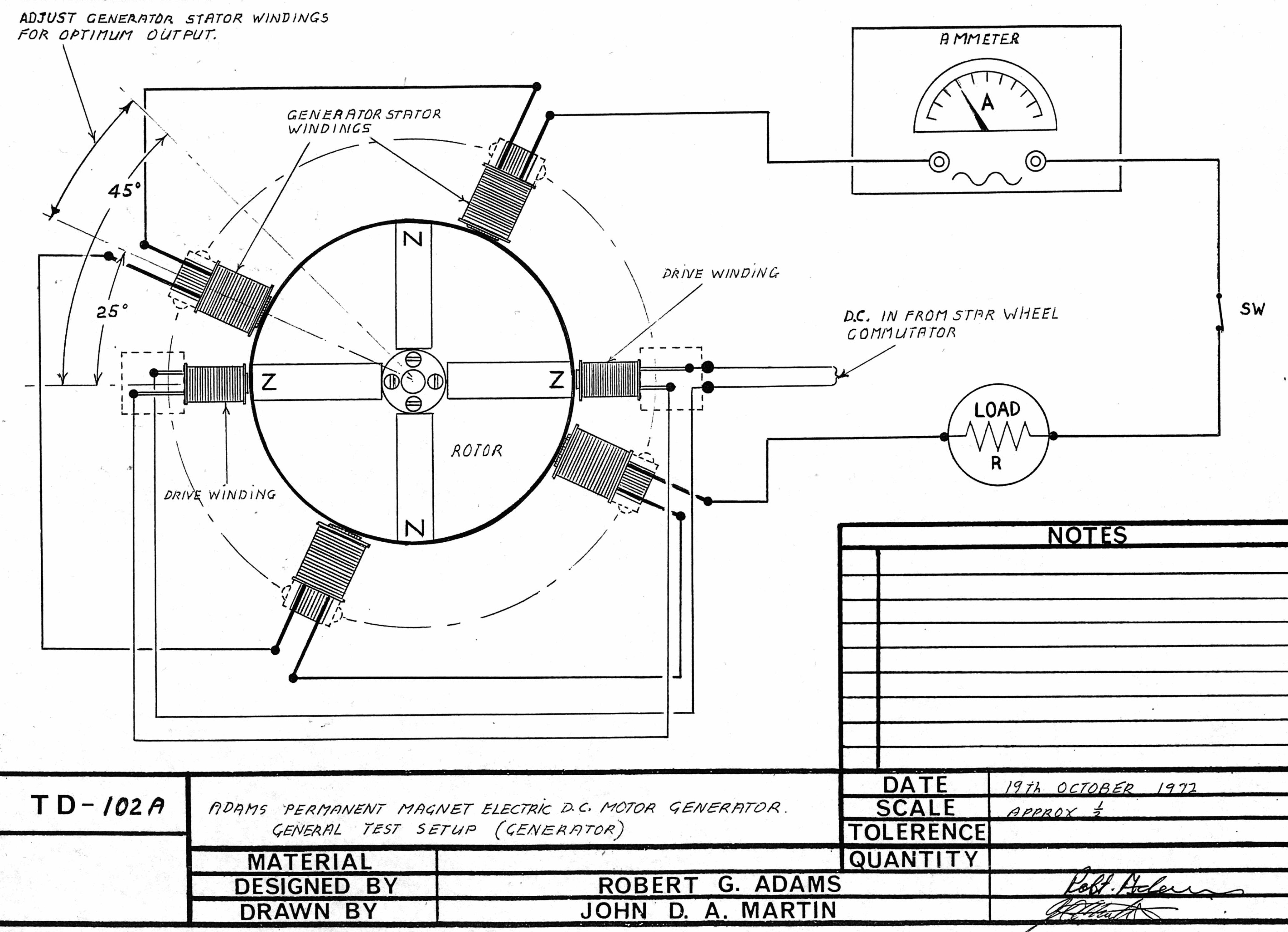
rexresearch.com
Tariel KAPANADZE
Over-Unity Electric
Videos --
http://www.youtube.com/watch?v=wV560xfYSJ0
http://www.youtube.com/watch?v=90W00Yt_PLk
http://www.youtube.com/watch?v=YxFgAfSXNt8
http://www.youtube.com/watch?v=Be1H0aq5Iyc
http://www.youtube.com/watch?v=Mxa_G4X8Y7k
http://www.youtube.com/watch?v=W-7RfEF-2WI
http://www.overunity.com/index.php?topic=7679( June 27, 2009 )
Self-running Free Energy Devices up to 5 KW from Tariel Kapanadze
Forcethetruth posted this video on Youtube that he got from a torrent somewhere:

http://www.youtube.com/watch?v=Mxa_G4X8Y7k
There are 7 parts to this video but the guys are lighting 5 large Edison based lightbulbs from a radiatorburied in the ground, a wire to a water pipe, a Tesla coil/joule thief, a spark gap, and some otherunidentified components.
We started discussing this in the Joule Thief topic but I wanted to give this its own area for discussion. We are looking for folks to help translate the narration in these videos.
These are well worth watching even not knowing the language spoken. It is really something to see. Theother 6 parts of the video can be found on youtube in the sidebar on the right of the video. If someonewants me to post links to all of them here, I will.
Bill
See also :
http://peswiki.com/index.php/Directory:Kapanadze_Free_Energy_Generator
http://v3.espacenet.com/publicationDetails/biblio?DB=EPODOC&adjacent=true&locale=en_EP&FT=D&date=20080828&CC=WO&NR=2008103130A1&KC=A1
WO 2008/103130
Energy Transformer
Abstract -- Energy transformer being improved with this invention, transforms the initial electric energyreceived from an independent power supply (1, 2, 2A) and comprises the following parts: - First partconsists of an accumulator or chargeable battery, or an inverter or network or any other power supply (1,2 and 2A) to provide the input energy to the system, - Second part consists of power switch (3),frequency generator (4), capacitor (5), first filter (6), and primary coil (7), - Third part consists ofsecondary coil (8), current amplifier (9), second filter (10), frequency adjuster (11) and phase stabilizer(12) and load (13), and - The cables (14 and 15) which connect the output (13) on the secondary side tothe power switch (3).
Background of the Invention
The present invention is related with an economic energy transformer, which primes the constant electricenergy received from any pwoer supply via transferring the electromagnetic field occurred at one of thebobbins to other bobbin, rhytmically stabilizing the magnetic field between the bobbins with the help ofamplifier immobilizes the energy voltage in both bobbins, increasing the current with respect to the inputcurrent.
Prior Art About The Invention
There is not encountered any application in prior art related with the invention improved with this invention.
2/8/2010 wo2008103130
rexresearch.com/…/kapanadze.htm 2/10
Aims for Development of the Invention
The economical energy transformer improved with this invention aims to receive a constant energy andfixing the voltage of this energy, increase the current value, in other words to produce more amount ofenergy than the received energy.
General Description of the Invention
The key feature of the economical energy transformer improved with this invention is to receive the electricenergy having constant voltage and current value and emit this energy with constant voltage but highercurrent value. This device can also feed the initial power supply.
The economical energy transformer improved with this invention has to receive energy from a powersupply constantly. This mentioned energy can be easily generated from a small accumulator or chargeablebattery or an inverter or a network or any similar power supply.
The economical energy transformer improved increasingly emits the energy that is received constantly.
Description of the Figures
The figures prepared for a better explanation of the economical energy transformer improved with thisinvention are disclosed. Description of the figures is as follows;
Figure 1 -- The view of circuit chart of the economical energy transformer.
2/8/2010 wo2008103130
rexresearch.com/…/kapanadze.htm 3/10
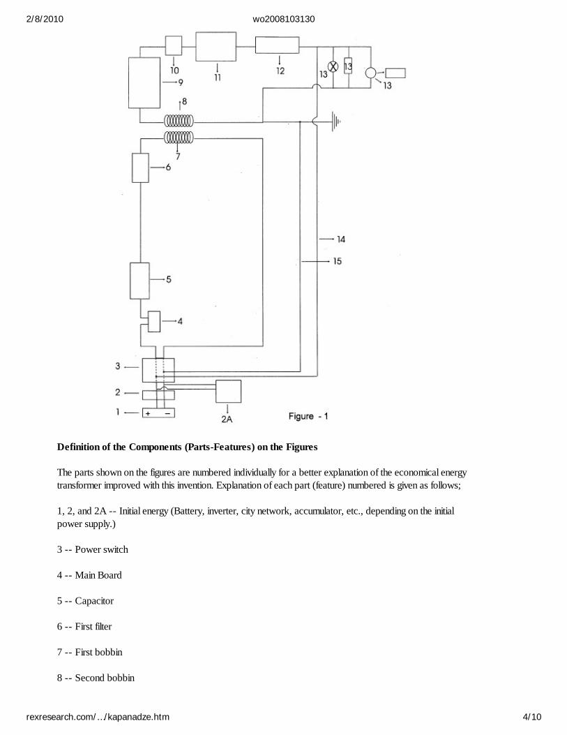
Definition of the Components (Parts-Features) on the Figures
The parts shown on the figures are numbered individually for a better explanation of the economical energytransformer improved with this invention. Explanation of each part (feature) numbered is given as follows;
1, 2, and 2A -- Initial energy (Battery, inverter, city network, accumulator, etc., depending on the initialpower supply.)
3 -- Power switch
4 -- Main Board
5 -- Capacitor
6 -- First filter
7 -- First bobbin
8 -- Second bobbin
2/8/2010 wo2008103130
rexresearch.com/…/kapanadze.htm 4/10

9 -- Current Amplifier
10 -- Second filter
11 -- Frequency Adjuster
12 -- Stabilizer (phase)
13 -- Output (load)
14 and 15 -- Energy cables to feed the first circuit with the energy generated.
Description of the Invention
The economical energy transformer improved with this invention includes 4 main part inside;
First Part consists of an accumulator or chargeable battery, or an inverter or network or any other powersupply (1, 2, and 2A) to provide the input energy to the system.
Second part consists of power switch (3), main board (4), capacitor (5), first filter (6), and first bobbin(7).
Third part of second bobbin (8), current amplifier (9), second filter (10), frequency adjuster (11) andstabilizer (phase) 912) and output (load) adjuster (13).
And the fourth part consists of the cables (14 and 15) which provide the energy generated to betransferred to the first part and by this way feeds the input power supply where necessary.
Second part is designed to transfer the electric energy -- which is received from the independent powersupply at the first part- and electromagnetic field -- which is occurred at the first bobbin (7) -- to thesecond bobbin (8).
And at the third part, due to the high magnetic field received from the first bobbin (7) there occurs adifference between the bobbins and this difference occurred between the second bobbin (8) and firstbobbin (7) is increased by the current amplifier (9) at this part.
Through the energy cables (14 and 15) connected to the output (load)(13) of the economical energytransformer improved with this invention and feeding the first circuit, the device feeds itself by using somepart of the energy it generated.
The present invention is designed as single phase and it is possible to increase the number of the phases atmaximum three phase. It is possible to generate energy at any desired power value. Depending on theelectric energy value (power), the capacities of the parts used in the device shall be increasedsymmetrically.
The energy to feed the system is received from an accumulator or chargeable battery, or an inverter ornetwork or any other power supply (1, 2 and 2A). This energy input has a constant voltage and currentvalue.
Opening the power switch (3), the user gives the electric energy received from the initial energy (1, 2, 2A)to the first second part. being loaded with the electric energy received from the energy supply (1, 2, 2A)the capacitor (5) serves as a pump, and provides the main board (4) to give electric to the system.
2/8/2010 wo2008103130
rexresearch.com/…/kapanadze.htm 5/10
Main Board (4) transfers the high amount of frequency it generated to the first filter (6). First filter (6)stabilizes the frequency received from the main board (4) and regularly transfers to the first bobbin (7).
Creating a magnetic field around itself with the high frequency regularly received from the first filter (6);first bobbin (7) transfers it to the second bobbin (8).
Subsequently, following the system, high frequency passing from the first bobbin (7) passes to the currentamplifier (9). Second filter (10) transfers the high frequency received to the high frequency adjuster (11).The energy emitted from this part passes to the stabilizer (12) and the relevant unit stabilizes the receivedhigh frequency in accordance with the need and arranges without causing any harm to the parts at its exit.Some part of the energy generated by the device is used to feed the energy cables (14 and 15) feeding thefirst circuit and the power supply where this power supply needs to be recharged.
http://v3.espacenet.com/publicationDetails/biblio?DB=EPODOC&adjacent=true&locale=en_EP&FT=D&date=20080828&CC=WO&NR=2008103129A1&KC=A1
WO 2008 / 103129
Independent Energy Device
Abstract -- The independent energy device improved with this invention, starts operation with the initialelectric energy received from the initial energy supply (15) and afterwards generates energy consistentlyand is characterized to include power switch (1), capacitor (2), points (3), high frequency generator (4),first filter (5), first bobbin (6), first frequency adjuster (7), second filter (8), frequency stabilizer (adjuster)(9), second bobbin (10), second frequency adjuster (11), exit (phase) (positive) (12), positive self feedingcable (12a), exit (neutral) (13), negative self feeding cable (13a), neutral (grounding) (14), initial powersupply (15).
Description of the Invention
The present invention is a device both self sufficient (self-feeding) and producing ready to use electricenergy, starts to operate with the initial electrical energy received from accumulator or similar source ofenergy, transferring the magnetic field generated in first bobbin to second bobbin through a frequencystabilizer, after rhythmically stabilizing the magnetic field occurred between the bobbons; converts theindependent energy -- received by the second bobbin from the air -- to electric energy.
Today electric energy can be generated by using various kinds of technologies. in order to summarizesome of them; electric energy can be generated through dams, from the motion of waves, by nuclearpower plants, by using solar energy, fuel oil, hydroelectric power plants and similar areas through usingvarious technologies. There are different advantages and disadvantages among these various techniquesused for generating electric energy. The general purpose of all these techniques is to generate energycheaper and faster by providing high efficiency.
The present invention is improved through using different technologies of today, by less costly way andwithout harming the nature, and using a very different technique from the above mentioned (presenttechniques used today).
The present invention receives energy externally only at first starting phase. This mentioned energy can beeasily generated from a small accumulator or chargeable battery or similar sources. 1-2 seconds after thedevice is started, the power switch at the energy input of the device cuts the external electric (from
2/8/2010 wo2008103130
rexresearch.com/…/kapanadze.htm 6/10
accumulator or similar source of energy) off by generating electric energy. A very small part of this electricenergy generated is used by the device to feed itself and the most part is discharged ready to be used. Aslong as the device is not shut down or no problem occurred inside, the device generates energyconsistently. By recent technology, there is no device similar to the present invention producing energyconsistently by feeding itself.
In order to maintain the device to generate electric energy consistently, two circuits are designed inside thedevice.
First circuit, consists of time relay switch, capacitor, points, high frequency generator, first filter, firstbobbin, first frequency adjuster (this circuit is displayed with bold line in the figure).
Second circuit; consists of second filter, frequency stabilizer, second bobbin, second frequency adjuster.
First circuit is designed for generating electricity by transferring the electromagnetic field occurred at thefirst bobbin with the electric energy received from the independent initial power supply, to second bobbin.And as the second circuit; Due to the high magnetic field received from the first bobbin, there occurs amagnetic field difference between the bobbins. The magnetic field difference occurred between the secondbobbin and first bobbin stabilized by the help of frequency stabilizer, this circuit lione also converts theenergy which is moving independently in the air at the second bobbin designed within this line to electricenergy. This electric energy formed by the second bobbin adjusts the necessary frequency (220 V - 50 Hzor 110 V - 60 hz) for use, by the help of second frequency adjuster designed at the bobbin output. Thisgenerated electric energy is transferred to the intended usage area via exit points. Through the circuitcables connected to the exit points, the device feeds itself with teh generated electric energy. Thismentioned process eventuates 1-2 seconds after the device is started. After this process, the time relaypower switch designed at the input of the device breaks the initial power supply. After this stage, thedevice generates the energy independently.
The present invention is designed as single phase and as the phase number is desires to be increased, thebobbin number shall also be increased for each phase. Depending on the number of bobbins, thecapacities of other parts used in the device are increased symmetrically.
It is possible to obtain energy in desired amounts of KW from the device. it is necessary to increase thecapacity of the parts depending on the value of the electric energy.
The figures related to the invention are given enclosed, from the related figures:
Figure 1 -- Schematic view of the present invention.
2/8/2010 wo2008103130
rexresearch.com/…/kapanadze.htm 7/10
The parts related to the invention are given numbers and the explanations corresponding to these numbersare as follows:
1 -- Power switch
2 -- Capacitor
3 -- Points (as distributor of an engine)
4 -- High frequency generator
5 -- First filter
6 -- First bobbin
7 -- First frequency adjuster
8 -- Second filter
9 -- Frequency stabilizer (adjuster)
10 -- Second bobbin
11 -- Second frequency adjuster
12 -- Exit (phase) (positive)
13 -- Exit (neutral)
2/8/2010 wo2008103130
rexresearch.com/…/kapanadze.htm 8/10

13a -- Negative transformation cable
14 -- Neutral (ground)
15 -- Initial power supply
A -- First circuit cable
B -- Second circuit cable
The operation of the present device is explained as below, giving reference to the parts numbers throughthe figure enclosed.
Energy and Frequency Circuit on the First Circuit (A)
Opening the power switch, the user gives the electric energy received from the initial energy supply (15) tothe first circuit cable (A). Being loaded with the electric energy received from the energy supply (15) thecapacitor (2) serves as a pump, and provides the points (3) to give electricity to the high frequencygenerator (4). High frequency generator (4) transfers the high amount of frequency it generated to the firstfilter (5). First filter (5) stabilizes the frequency received from the high frequency generator (4) andregularly transfers to the first bobbin (6). Creating a magnetic field around itself with the high frequencyregularly received from the first filter (5); first bobbin (6) transfers it to the second bobbin (10).Subsequently, following the first circuit cable (A), the high frequency passing from the first bobbin (6)passes to the first frequency adjuster (7). The first frequency adjuster (7) stabilizes the received highfrequency in accordance with the need and arranges without causeing any harm to the parts at its exit.
Energy and Frequency Circuit on the Second Circuit (B)
The high frequency rising from the first bobbin (6) enters the second filter through the second circuit (B).Second filter (8) transfers the frequency received from the first bobbin (6) to the frequency stabilizer (9).The electromagnetic fields occurring at the bobbins (6, 10) are different and the magnetic field at the firstbobbin (6) is higher than the second bobbin (10). At this stage the frequency stabilizer (9) stabilises thedifferent electromagnetic fields occuring at the first and second bobbins (6, 10). This stabilized highfrequency exits from the second bobbin (10) and is adjusted for the required (necessary for the use)frequency degree by the help of the second frequency adjuster (11). The user uses the electric energygenerated in the device by the help of exit (phase) (positive) (12) and exit (neutral) cable (13).
The positive transformation cable (12A) at the exit of the device and the negative transformation cable(13A) are connected to the power switch. 1-2 seconds after the device starts to generate electricity, theelectric energy generated is transmitted to the power switch (1) via positive transformation cable (12A)and negative transformation cable (13A). The time relay at the power switch (1) breaks the energyreceived from the initial power supply (15). After this stage, the device continues to generate electricenergy feeding itself with the self-generated energy and independently without depending on any energyfrom outside. The device continues to generate unlimited energy as long as it is not closed via the powerswitch (1) or no problem occurs within the system.
Your Support Maintains this Service -- and Your Survival ...
The Rex Research Civilization Kit
2/8/2010 wo2008103130
rexresearch.com/…/kapanadze.htm 9/10
LIST OF ALL CITATIONS4 documents citing US4237391 (A)5 documents cited in relation to US4237391 (A)Sorting criteria: Priority Date Inventor Applicant Ecla
PATENTS CITED IN THE SEARCH REPORT
1 Device for producing a current
Inventor: JAN VOLGER Applicant: PHILIPS CORP
EC: G11C11/44; H01F6/00C; (+2) IPC: G11C11/44; H01F6/00; H01L39/00; (+5)
Publicationinfo:
US3336489 (A) - 1967-08-15 Priority Date: 1962-09-12
2APPARATUS FOR GENERATING AN ELECTRIC CURRENT IN ASUPERCONDUCTIVE COIL
Inventor: MASSAR ERNST Applicant: SIEMENS AG
EC: H01F6/00; H01F6/00C; (+1) IPC: H01F6/00; H02K55/00; H01F6/00; (+3)
Publicationinfo:
US3427482 (A) - 1969-02-11 Priority Date: 1965-03-24
3 SUPERCONDUCTIVE POWER APPARATUS
Inventor: SMITH STUART H JR Applicant: STUART H SMITH JR
EC: H02K55/00 IPC: H02K55/00; H02K55/00; (IPC1-7): H02K1/20; (+2)
Publicationinfo:
US3469121 (A) - 1969-09-23 Priority Date: 1964-10-21
4 SUPERCONDUCTING DYNAMOELECTRIC MACHINE
Inventor: MCFARLANE IAN DUNCAN Applicant: NAT RES DEV
EC: H02K55/00 IPC: H02K55/00; H02K55/00; (IPC1-7): H02K9/10
Publicationinfo:
US3560773 (A) - 1971-02-02 Priority Date: 1966-06-16
5ROTARY ELECTRIC AC GENERATOR UTILIZING THE MAGNETICSHIELDING AND TRAPPING BY SUPERCONDUCTING PLATES
Inventor: KAWABE USHIO ; DOI TOSHIO (+3) Applicant: HITACHI LTD
EC: H02K55/00 IPC: H02K55/00; H02K55/00; (IPC1-7): H02K;(+1)
Publicationinfo:
US3564307 (A) - 1971-02-16 Priority Date: 1968-07-24
LIST OF CITING DOCUMENTS
6 ENERGY GENERATING APPARATUS WITH MAGNET
Inventor: JANG SOON-GIL [KR] Applicant: JANG SOON GIL [KR]
EC: H02K53/00 IPC: H02N15/00; H02K53/00; H02K55/00; (+4)
Publicationinfo:
WO0042701 (A1) - 2000-07-20 Priority Date: 1999-01-09
7 Static field converter
Inventor: ABOLAFIA ANDREW [US] Applicant: ABOLAFIA, ANDREW
EC: H02K19/18; H02K21/40 IPC: H02K19/18; H02K21/40; H02K55/06; (+4)
Publicationinfo:
US5710531 (A) - 1998-01-20 Priority Date: 1996-05-29
8 Superconductor motor provided with superconductor shield
Inventor: KAMBE YOSHITAKA [JP] ; SHINOZAWATAMIO [JP]
Applicant: TOYOTA MOTOR CO LTD [JP]
EC: H02K55/06 IPC: H02K55/06; H02K55/00; (IPC1-7): H02K55/00; (+1)
Publicationinfo:
US5723925 (A) - 1998-03-03 Priority Date: 1995-05-15
9Electric current generator including torque reducingcountermagnetic field
Inventor: GERMAN JAMES W [US] Applicant: GERMAN JAMES W [US]
EC: H02K21/38 IPC: H02K21/38; H02K21/00; (IPC1-7): H02K1/12
Publicationinfo:
US5191258 (A) - 1993-03-02 Priority Date: 1991-09-11
Data supplied from the espacenet database — Worldwide
2/8/2010 espacenet — All citations list view
http://v3.espacenet.com/allCitations?… 1/2

pp espacenet2/8/2010 espacenet — All citations list view
http://v3.espacenet.com/allCitations?… 2/2

MODERN RADIANT ENERGY CIRCUITPosted October 22, 2004 - updated December 28, 2007
Modern Perreault Conversion Circuit
DESCRIPTION
1. S1 is closed first to charge C1. Once C1 is charged S2 is closed to initiate the tank circuit.
2. The automobile ignition coil transforms the high voltage on the primary side to a lower voltage at a highercurrent.
2/8/2010 Modern Radiant Energy Circuit
nuenergy.org/…/modern_radiant_ener… 1/3
3. The primary is tuned to the secondary for resonance.
4. A pre-glow discharge is present in the ion valve.
5. Electrons are created in the ion valve through ultraviolet light (radiant energy) reactions. The valve is an energymultiplying transducer.
6. The insulated wire and ground serve as a source of ambient voltage potential.
Basic Tesla Conversion Circuit
Reference
http://www.nuenergy.org/alt/radiant_energy_diatribe
Alternative Energy Research ArchiveNu Energy Horizons, P. O. Box 22, Rumney, New Hampshire 03266-0022 USA
Copyright © 2004 & 2005 All Rights Reserved
2/8/2010 Modern Radiant Energy Circuit
nuenergy.org/…/modern_radiant_ener… 2/3

2/8/2010 Modern Radiant Energy Circuit
nuenergy.org/…/modern_radiant_ener… 3/3
PESWiki.com -- Pure Energy Systems Wiki: Finding and facilitating breakthrough clean energy technologies.
OS:Radiant Energy Antenna SystemFrom PESWiki
A search for impinging designs with "prior art" IP claims is under way, and so far does not seem toinclude any significant competing designs. Please see 'Related Designs'
— Radiant Energy Antenna System Team.
OS:Radiant Energy Antenna System is a simple replication of the well known method for generating power,which is related to Nikola Tesla research. This article was originally disclosed by Mark Eldridge.
Contents1 Building the Radiant Battery Charger
1.1 A Word about Capacitors1.2 Silicon Controlled Rectifier (S.C.R.)1.3 Where Do I Put It?1.4 The Procedure1.5 Diagram1.6 Parts List1.7 Setup1.8 Variation on the setup
2 Related Designs3 Comments4 Patents and external articles
2/8/2010 OS:Radiant Energy Antenna System - …
peswiki.com/…/OS:Radiant_Energy_A… 1/13
5 See Also
Building the Radiant Battery ChargerI must preface this by saying that after setting this up I was VERY disappointed in the results I got. I couldn’t getthe dead battery to take more than 8 volts charge in the first 24 hours, which was the controlled test I wanted torun. Then to really rub it in, on my third day of writing this I received a copy of the new book by Tom Bearden andJohn Bedini titled Free Energy Generation, 20 Bedini-Bearden years, and was taken aback by the fact that the verysame setup I show you here is also in their new book. Sure they drew it up differently than I was going to show it,but even having said that, there are things about this setup that are not told to you in Bearden’s book.
Those of you who have read the writings of the well known "Free Energy"? researchers like Bearden or Bediniknow that they have tried to teach the general public about how simple it is to build this type system. Their biggestdrawback is the fact that they are so far beyond what most people know about electrical circuits that they turnpeople off with their 15 letter high-tech wording. They understand what they mean when they say something, butmost are simply blown away with the techno-word-ology they use. It gives people an uneasy sense of inferiority.The technology they have brought forth needs to be given to people in ways they can actually understand. Mostpeople, given the right teacher, can grasp any concept.
Knowing exactly, precisely what’s going on in this setup and how it does what it does isn’t necessary to get results.However there are some things you should know about how the process manifests itself. I could write volumes onwhat is happening, but it would only serve to confuse. Different people call the same effect by different names; thisonly helps to further the confusion. After reading this and seeing for yourself how it functions, you’ll begin to get anidea of how the other systems I’ll write about actually work. They all have basically the same energy running them,some will utilize a mechanical method of input, other’s will use a natural input. So here goes, in the simplest languageI know how to use.
In the "normal" way of charging batteries, we plug in our charger to our wall outlet and hook the leads up to positiveand negative, this much makes sense to anyone, but the actions taking place in the inner workings of the battery areof major importance. In our "normal" scenario we are pushing (quite violently) the ions in the electrolyte (batteryacid) backward, toward the negative sides of the plates. This causes heat and is classified as a "positive electricalevent". This is why in the "normal" re-charging process the battery gets warm. Any action that causes heat to begenerated is not generally considered to be radiant, ether, or any type of free energy. There are exceptions, ofcourse, but we won’t go into those in this paper.
Our setup will work in a way that pulls the ions toward the negative plates of the battery. This is known in thescientific community as a form of implosion. Negative Electromagnetic energy converges, while positive energydiverges (expansion or explosion, rather than implosion). When hooked up to re-charge in this way the battery willbe cold to the touch.
Nikola Tesla described the way he used energy pulses as a "disruptive discharge". Tom Bearden calls it "sharpgradients". But no matter what you call it, the basis of the technique is the same. That is to gather energy or voltagepotential, in a capacitor and then abruptly discharge the stored energy across the load, which in our case will be abattery which will be gated from the negative (earth) side using a Silicon Controlled Rectifier (SCR) and a smallneon bulb which will time the discharges as a kind of spark gap.
A Word about Capacitors
There are different kinds of capacitors you can use for this setup. Capacitors called Electrolytic are made for direct
2/8/2010 OS:Radiant Energy Antenna System - …
peswiki.com/…/OS:Radiant_Energy_A… 2/13
current (D.C.) applications only. In this system you can use Electrolytic or the Ceramic (disc) type. Electricity foundin nature is usually D.C. Although D.C. actually can and usually does have a very high (Millions of cycles persecond) frequency. Most instrumentation shows D.C. as a straight line at a given amount of voltage (actually 13.5volts on a regular deep cell battery considered to be 12 volts) but is not really a steady source but is actuallyresonating at millions of cycles per second. The energy gathered by natural D.C. sources can be utilized locallywhere it is collected. When deciding what capacitor you will need, try to remember that the voltage ratings of agiven capacitor is for reference if they are used in a "normal" circuit. When placing them into our system we aren’tlimited to the voltage that a particular capacitor is rated at because we are using another type of energy in it. Thevalue, in Microfarads, can be 3 to 10. In our setup shown here the capacitor is 10 Mfd.
Those of you who have studied the works of John Bedini know that in some of his references he states that hissystem of recharging provides a magnitude of negative voltage in the hundreds of thousands of volts. His systemsdon’t blow up or melt down because he tunes them to use negative energy, which was said earlier to be convergentenergy, not normal divergent energy. This is how he gets away with using SCR’s rated at 800 volts, even thoughthere could be hundreds of thousands of (negative) volts going through them. The same holds true for the capacitorused in the system.
Silicon Controlled Rectifier (S.C.R.)
The SCR we use will always be the same one regardless of the system it is put in. If it’s good enough for Bedini, it’sgood enough for us. It is rated at 800 volts, 50 Amps. The Amps (current) rating isn’t important so we buy onerated in the lower current range, since current isn’t a factor. This SCR shouldn’t cost more than $5 or $6 (US). Ifyou wish to, you can spend hundreds $$$ on ones that are rated with higher current values, but there’s no need todo so.
Where Do I Put It?
When figuring out where to put your system you will have to take into consideration what surroundings you have towork with. If you have a large farm, space won’t be a factor, but if you are living the city or suburbs, your choice ofwhere to put the antenna will be limited. The standard to use when figuring your available potential, one would needto see what height you will place the antenna then multiply that height by 200 volts per meter of height from theground. Some who have built these antenna systems use 300 volts per meter as their voltage calculation factor.Remember, the negative energy will be very forgiving even if you’re using what you think may be an under-ratedcapacitor.
The Procedure
The overall process is very simple and straightforward. Tesla showed us how to do this over 100 years ago.Whether we are mechanically providing the radiant potential or getting it from nature, this system and others like itare about to become widespread. Even if you don’t have the time to build it now, order the parts and have them sothat when the time arrives you won’t be scrambling for them and you’ll be able to keep your water well going andprovide some kind of comfort for yourself and family. Just get the parts listed and put it together or store them forfuture use.
Those of you who put the system together and have disappointing results as I did, don’t give up or throw out theparts. In the next pdf file I send out I will show you how to mechanically induce the energy using the same S.C.R.and capacitor and have a reliable system that I believe anyone can build.
Tinkering with it will be fun, and you’ll discover that if you have younger children, they will be interested in it alsoand that’s a good thing since this is probably what they will be using in the future. (Sooner than you may think)
2/8/2010 OS:Radiant Energy Antenna System - …
peswiki.com/…/OS:Radiant_Energy_A… 3/13
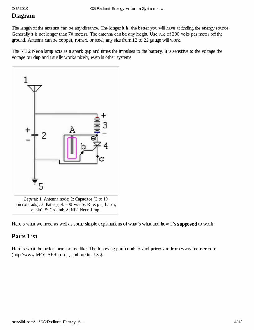
Diagram
The length of the antenna can be any distance. The longer it is, the better you will have at finding the energy source.Generally it is not longer than 70 meters. The antenna can be any hieght. Use rule of 200 volts per meter off theground. Antenna can be copper, romex, or steel; any size from 12 to 22 gauge will work.
The NE 2 Neon lamp acts as a spark gap and times the impulses to the battery. It is sensitive to the voltage thevoltage buildup and usually works nicely, even in other systems.
Legend: 1: Antenna node; 2: Capacitor (3 to 10microfarads); 3: Battery; 4: 800 Volt SCR (e: pin; b: pin;
c: pin); 5: Ground; A: NE2 Neon lamp.
Here’s what we need as well as some simple explanations of what’s what and how it’s supposed to work.
Parts List
Here’s what the order form looked like. The following part numbers and prices are from www.mouser.com(http://www.MOUSER.com) , and are in U.S.$
2/8/2010 OS:Radiant Energy Antenna System - …
peswiki.com/…/OS:Radiant_Energy_A… 4/13
The Capacitor:75-TVA1963Vishay-Sprague 600V 10uF
$15.37
The SCR:511-BTW69-800STMicroelectronics TO-3P 50 Amp 800 Volt
$4.70
The NE-2:606-A2BChicago Miniature T-2 65VAC .7mA NE-2V
$0.50
Sub Total: $20.57 Shipping: To Be Determined TOTAL: $20.57
Setup
Let’s Go Outside and Set It Up
We’ll find a place for the antenna, and then bring the wire down to the place where you’re going to actually chargethe battery. If you’re trying this with a lead-acid battery make sure it is up to level with water or electrolyte. In thissetup I’m going to use enameled copper wire for the antenna. I used #22 wire which is thin, but should handle whatI’m trying to show here.
I’m going to attach the wire to a 10 foot tall (3 meter) board using staples and then nail the board upright against afence, then string the wire along an existing fence or some other means of support. I will make this antenna 110 feetlong, (33 meters) including the part nailed to the board that will stand up for the antenna height.
Then we hook up our parts as shown on the next page. Capacitor positive lead and the antenna lead directly to ourbattery junction (at the battery post) and the negative lead from our capacitor to the negative point at the rod wewill hammer into the ground. I had the copper ground rod in my shop already but they are available at any goodhardware store as well as any wire you may need.
2/8/2010 OS:Radiant Energy Antenna System - …
peswiki.com/…/OS:Radiant_Energy_A… 5/13
Then the Negative battery post to our S.C.R with our NE-2 across the leads as shown in the photo. (Middle leadto battery neg.) The left lead from the S.C.R. joins our other lead from the capacitor at our ground, via the rod Ihammered into the ground.
2/8/2010 OS:Radiant Energy Antenna System - …
peswiki.com/…/OS:Radiant_Energy_A… 6/13
NOTEIf you can actually see the NE-2 lighting up or flashing consider yourself lucky because you’ve founda great source of energy. Most of us probably won’t see it light up, and a few will occasionally see aflicker like a dying candle. THAT’S IT!!!!! Just measure the voltage of your charging battery beforeyou hook it up to the setup. Also write down the time of day you started and track the recharging.
Variation on the setup
I want to also show a variation to this style setup. The reason I show this here is to give you an idea how you cansetup an overshoot mechanism to dump excess energy should a thunderstorm or heavy rain come to your area whiletrying to use this setup to recharge a battery. I will say here and now that I have never tried this overshoot circuit,and as such can not offer any first hand experience regarding the effectiveness of the overshoot section.
The spark gaps on the left hand side of the drawing are further apart than the gap in the middle, and as such areactually used as a sort of resistor setup to act as an overshoot mechanism in case the larger spark gap receives toomuch energy from the antenna, like during a thunderstorm.
This drawing was taken from U.S. Patent 1540998 (http://patft.uspto.gov/netacgi/nph-Parser?patentnumber=1540998) (G.patent (http://www.google.com/patents?q=1540998) ; PDF (http://www.pat2pdf.org/pat2pdf/foo.pl?
2/8/2010 OS:Radiant Energy Antenna System - …
peswiki.com/…/OS:Radiant_Energy_A… 7/13
number=1540998) ), assigned to Hermann Plauson. If anyone tries this particular setup please inform the group of results
1: Antenna node; 2: Capacitor (3 to 10 microfarads); 3: Capacitor and spark gap; 4:Capacitor and spark gap; 5: Capacitor and spark gap; 6: Large spark gap; 7: Capacitor;
8: Isolation transformer; 9: Electrostatic motor; 0: Ground.
This is how the overshoot would be incorporated into the original S.C.R. style setup.
2/8/2010 OS:Radiant Energy Antenna System - …
peswiki.com/…/OS:Radiant_Energy_A… 8/13
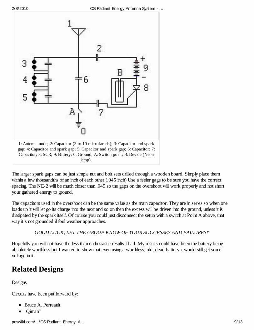
1: Antenna node; 2: Capacitor (3 to 10 microfarads); 3: Capacitor and sparkgap; 4: Capacitor and spark gap; 5: Capacitor and spark gap; 6: Capacitor; 7:Capacitor; 8: SCR; 9: Battery; 0: Ground; A: Switch point; B: Device (Neon
lamp).
The larger spark gaps can be just simple nut and bolt sets drilled through a wooden board. Simply place themwithin a few thousandths of an inch of each other (.045 inch) Use a feeler gage to be sure you have the correctspacing. The NE-2 will be much closer than .045 so the gaps on the overshoot will work properly and not shortyour gathered energy to ground.
The capacitors used in the overshoot can be the same value as the main capacitor. They are in series so when oneloads up it will let go its charge into the next and so on then the excess will be driven into the ground, unless it isdissipated by the spark itself. Of course you could just disconnect the setup with a switch at Point A above, thatway it’s not grounded if foul weather approaches.
GOOD LUCK, LET THE GROUP KNOW OF YOUR SUCCESSES AND FAILURES!'
Hopefully you will not have the less than enthusiastic results I had. My results could have been the battery beingabsolutely worthless but I wanted to show that even using a worthless, old, dead battery it would still get somevoltage in it.
Related DesignsDesigns
Circuits have been put forward by:
Bruce A. Perreault"Qiman"
2/8/2010 OS:Radiant Energy Antenna System - …
peswiki.com/…/OS:Radiant_Energy_A… 9/13
Paul ClintLawrence Rayburn
References and evidence
Radiant Energy Diatribe (http://www.nuenergy.org/alt/radiant_energy_diatribe.htm) between Paul Clint andBruce PerreaultModern Perreault Conversion Circuit(http://www.nuenergy.org/experiments/modern_radiant_energy_circuit.htm) - Posted October 22, 2004 -updated October 14, 2005
CommentsDocument
To Bruce A. Perreault:I had a 200' antenna hanging over my house going to a cap almost 5 years before this website:http://www.nuenergy.org/alt/radiant_energy_diatribe.htmYou NEVER invented this concept and nobody copied you, if anything seeing I was doing this before theabove posted website, it is more than obvious that you probably copied me!My experiment predates your letters from 2001+ as well. Soon you'll be claiming you invented electricity.(from User_talk:Qiman)
This document "Radiant Energy Antenna System" was given to me, a few days ago by Mark. Uponchecking it out, and sending it to a friend, i got asked if "Lawrence Rayburn" had given it to me. Iwatched the document that the friend sent, claiming I got the document from Lawrence Rayburn, andforwarded it to Mark. I don't think anyone came first with this one anymore, and no-one should claim"first". It's all Nikola Tesla anyway. (from User_talk:esaruoho)
Response from Bruce A. Perreault
If you read the article that I posted on the above referenced webpage...http://www.nuenergy.org/alt/radiant_energy_diatribe.htm I never claimed that I invented the circuit. Clearly, NikolaTesla was the first which is seen through his U.S. patent numbers [685,957(http://www.freepatentsonline.com/685957.pdf) ] and [685,958 (http://www.freepatentsonline.com/685958.pdf) .However, I did provide the circuit in the article that utilizes modern parts. I have since designed improved circuitsthat are used to convert a narrow band of radiant energy into useful electrical current. The 'radiant energy antenna'is a passive static electric converter that demonstrates how static electricity can be transformed into electricalcurrent.
In Tesla's patents he uses a polished plate that was the first crude solar cell. Electrons are ejected from the platewhen it is exposed to sunlight. In patent number [685,957 (http://www.freepatentsonline.com/685957.pdf) ] heuses ultraviolet light and cathode rays to ionize the air to charge his system. In patent number [685,958(http://www.freepatentsonline.com/685958.pdf) ] only a cathode ray tube is used to demonstrate his system.
What is truly unique on the webpage is Paul Clint's coax cable generator. I have not heard of anyone doing thisbefore February 3, 2003.
-Bruce A. PerreaultJanuary 15, 2007
2/8/2010 OS:Radiant Energy Antenna System - …
peswiki.com/…/OS:Radiant_Energy_A… 10/13
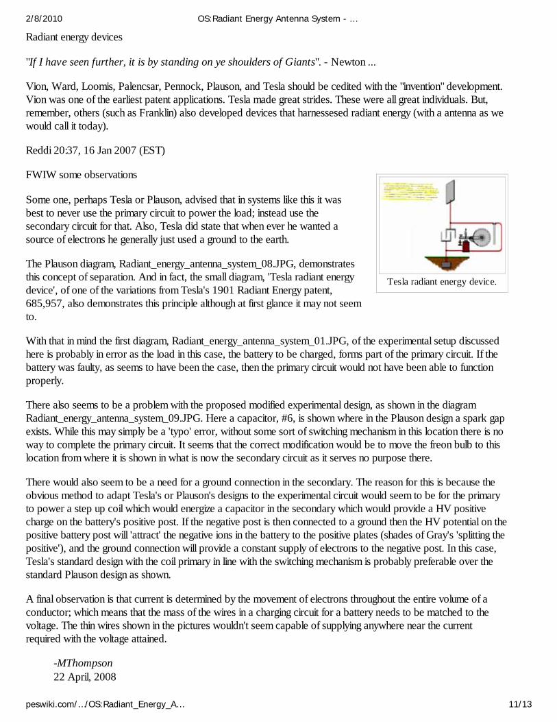
Tesla radiant energy device.
Radiant energy devices
"If I have seen further, it is by standing on ye shoulders of Giants". - Newton ...
Vion, Ward, Loomis, Palencsar, Pennock, Plauson, and Tesla should be cedited with the "invention" development.Vion was one of the earliest patent applications. Tesla made great strides. These were all great individuals. But,remember, others (such as Franklin) also developed devices that harnessesed radiant energy (with a antenna as wewould call it today).
Reddi 20:37, 16 Jan 2007 (EST)
FWIW some observations
Some one, perhaps Tesla or Plauson, advised that in systems like this it wasbest to never use the primary circuit to power the load; instead use thesecondary circuit for that. Also, Tesla did state that when ever he wanted asource of electrons he generally just used a ground to the earth.
The Plauson diagram, Radiant_energy_antenna_system_08.JPG, demonstratesthis concept of separation. And in fact, the small diagram, 'Tesla radiant energydevice', of one of the variations from Tesla's 1901 Radiant Energy patent,685,957, also demonstrates this principle although at first glance it may not seemto.
With that in mind the first diagram, Radiant_energy_antenna_system_01.JPG, of the experimental setup discussedhere is probably in error as the load in this case, the battery to be charged, forms part of the primary circuit. If thebattery was faulty, as seems to have been the case, then the primary circuit would not have been able to functionproperly.
There also seems to be a problem with the proposed modified experimental design, as shown in the diagramRadiant_energy_antenna_system_09.JPG. Here a capacitor, #6, is shown where in the Plauson design a spark gapexists. While this may simply be a 'typo' error, without some sort of switching mechanism in this location there is noway to complete the primary circuit. It seems that the correct modification would be to move the freon bulb to thislocation from where it is shown in what is now the secondary circuit as it serves no purpose there.
There would also seem to be a need for a ground connection in the secondary. The reason for this is because theobvious method to adapt Tesla's or Plauson's designs to the experimental circuit would seem to be for the primaryto power a step up coil which would energize a capacitor in the secondary which would provide a HV positivecharge on the battery's positive post. If the negative post is then connected to a ground then the HV potential on thepositive battery post will 'attract' the negative ions in the battery to the positive plates (shades of Gray's 'splitting thepositive'), and the ground connection will provide a constant supply of electrons to the negative post. In this case,Tesla's standard design with the coil primary in line with the switching mechanism is probably preferable over thestandard Plauson design as shown.
A final observation is that current is determined by the movement of electrons throughout the entire volume of aconductor; which means that the mass of the wires in a charging circuit for a battery needs to be matched to thevoltage. The thin wires shown in the pictures wouldn't seem capable of supplying anywhere near the currentrequired with the voltage attained.
-MThompson22 April, 2008
2/8/2010 OS:Radiant Energy Antenna System - …
peswiki.com/…/OS:Radiant_Energy_A… 11/13
Patents and external articlesU.S. Patent 685957 (http://patft.uspto.gov/netacgi/nph-Parser?patentnumber=685957) (G.patent
(http://www.google.com/patents?q=685957) ; PDF (http://www.pat2pdf.org/pat2pdf/foo.pl?number=685957) ) Nikola Tesla PatentU.S. Patent 685958 (http://patft.uspto.gov/netacgi/nph-Parser?patentnumber=685958) (G.patent
(http://www.google.com/patents?q=685958) ; PDF (http://www.pat2pdf.org/pat2pdf/foo.pl?number=685958) ) Nikola Tesla PatentU.S. Patent 1540998 (http://patft.uspto.gov/netacgi/nph-Parser?patentnumber=1540998) (G.patent
(http://www.google.com/patents?q=1540998) ; PDF (http://www.pat2pdf.org/pat2pdf/foo.pl?number=1540998) ) Hermann PlausonPatent
Harnessing Nature's Electricity (http://www.nuenergy.org/alt/harnessing_nature's_electricity.htm)Hermann Plauson's Book on Converting Atmospheric Electricity (http://www.nuenergy.org/zip/plauson.zip)
Bruce A. Perreault, "Nikola Tesla's Radiant Energy System(http://www.nuenergy.org/alt/tesla_energy.htm) "Bruce Perreault, "New Generation of Radiant Energy Devices(http://www.nuenergy.org/alt/Exotic%20Research%20New%20Generation.htm) "
See AlsoOS:Ambient_Energy_Collection_DeviceOS:RED ELF
- Other Open Source Projects- PESWiki main index- PES Network Inc. (http://pureenergysystems.com)
Retrieved from "http://peswiki.com/index.php/OS:Radiant_Energy_Antenna_System"
See also:
"When you're one step ahead of the crowd you're a genius.
Ads by Google DIY Antenna Booster Free Energy Posters Electric Car Battery Charger Battery Recondition Battery Resurrection Guide
2/8/2010 OS:Radiant Energy Antenna System - …
peswiki.com/…/OS:Radiant_Energy_A… 12/13

When you're two steps ahead, you're a crackpot." -- Rabbi Shlomo Riskin (Feb. 1998)
This page was last modified 08:18, 22 April 2008.This page has been accessed 24,183 times.Content is available under GNU Free Documentation License 1.2.About PESWikiDisclaimers
2/8/2010 OS:Radiant Energy Antenna System - …
peswiki.com/…/OS:Radiant_Energy_A… 13/13