Embed Size (px)
Citation preview
Dolby SurroundMixing Manual
Issue 01
®
Dolb y Surround Mi xing M anual
ii
Dolb y Labo ratories Lice nsing Corporation
USA 100 Potrero AvenueSan Francisco, CA 94103-4813415-558-0200Facsimile 415-863-1373
UK Wootton BassettWiltshire SN4 8QJ EnglandPhone (44) 1793-842100Facsimile (44) 1793-842101
The Dolby Surround Mixing Manual is available in two formats: Vertical pages andhorizontal pages. The vertical format, publication S98/11932, is designed for printing toUS letter or A4 size paper. The horizontal format, publication S98/11931, has beencreated to facilitate on-screen viewing. Both versions are available on the DolbyLaboratories web site at www.dolby.com/tech/.
Issue 1
S98/11932
Dolby, Pro Logic, AC-3 and the double-D symbol are trademarks of Dolby Laboratories
1998 Dolby Laboratories
Dolby Surround Mixing Manual
iii
Table of Contents
List of Figures ..............................................................................................................vi
List of Tables .............................................................................................................. viii
Chapter 1 Introduction .............................................................................................. 1-1
Chapter 2 Technical Guidelines ............................................................................... 2-12.1 Equipment from Dolby Laboratories ........................................................... 2-1
2.1.1 Dolby Model SEU4 Surround Encoding Unit .................................. 2-12.1.2 Dolby Model SDU4 Surround Decoding Unit.................................. 2-1
2.2 System Information ..................................................................................... 2-22.2.1 Room Layouts................................................................................. 2-22.2.2 Control Rooms................................................................................ 2-22.2.3 Remote Trucks ............................................................................... 2-32.2.4 Critical Listening Rooms................................................................. 2-32.2.5 Consumer Decoders....................................................................... 2-4
2.3 Additional Equipment Required .................................................................. 2-52.3.1 Speakers and Amplifiers................................................................. 2-52.3.2 Center Channel Speaker ................................................................ 2-72.3.3 Smaller Center Channel Speakers ................................................. 2-92.3.4 Surround Channel Speakers ........................................................ 2-102.3.5 Surround Speaker Location.......................................................... 2-102.3.6 Audio Consoles ............................................................................ 2-112.3.7 Monitor Path ................................................................................. 2-112.3.8 Speaker Sound Pressure Level.................................................... 2-132.3.9 SPL Meters................................................................................... 2-142.3.10 Phase Scope ................................................................................ 2-14
Chapter 3 System Installation .................................................................................. 3-13.1 Signal Routing Audio Connections ............................................................. 3-13.2 Signal Flow Options - Encoder ................................................................... 3-1
3.2.1 Basic Recording Setup with Auxiliary Buss Surround Feed ........... 3-13.2.2 Basic Recording Setup with Film Panning Console ....................... 3-23.2.3 Basic Recording Setup with 2 Stereo Buss Output ........................ 3-2
3.3 Signal Flow Options - Decoder................................................................... 3-33.3.1 Recording Setup with Monitor Section of Console ......................... 3-33.3.2 Recording Setup with Surround-Ready Monitor Section of Console .. 3-33.3.3 Live Broadcast Setup ..................................................................... 3-43.3.4 Live Broadcast Setup with Fail-Safe............................................... 3-43.3.5 Monitoring Music Premixes for Film................................................ 3-5
Dolby Surround Mixing Manual
iv
3.4 Dolby Model SEU4 Setup ........................................................................... 3-63.4.1 Surround Active LED...................................................................... 3-63.4.2 EPL Loop Switch ............................................................................ 3-6
3.5 Dolby Model SDU4 setup ........................................................................... 3-73.5.1 Internal Switches - CAT 344 information ........................................ 3-73.5.2 Center Speaker Switch................................................................... 3-83.5.3 Wake-up State................................................................................ 3-93.5.4 Local/Remote Fader ....................................................................... 3-93.5.5 EPL Switch ................................................................................... 3-10
3.6 Cat 150E Card Settings ............................................................................ 3-113.6.1 Bass Splitting Modification ........................................................... 3-113.6.2 Time Delay Calculations............................................................... 3-12
Chapter 4 System Set-Up .......................................................................................... 4-14.1 Encoder Alignment ..................................................................................... 4-14.2 Decoder Alignment ..................................................................................... 4-2
4.2.1 Input Levels .................................................................................... 4-24.2.2 Output Levels ................................................................................. 4-3
4.3 Room EQ .................................................................................................... 4-34.3.1 ANSI/SMPTE 202M X-Curve .......................................................... 4-44.3.2 ANSI/SMPTE 222M Modified X-Curve ........................................... 4-44.3.3 Recording Studios - Music Mixing .................................................. 4-54.3.4 Near-Field Monitors........................................................................ 4-5
Chapter 5 Mixing Techniques ................................................................................... 5-15.1 Announcers and Dialog .............................................................................. 5-15.2 Interior Effects ............................................................................................ 5-15.3 Positioning of the Stereo Image.................................................................. 5-15.4 Panning Sounds ......................................................................................... 5-25.5 Stacking Encoded Tracks ........................................................................... 5-35.6 Magic Surround .......................................................................................... 5-35.7 Decoder Mistracking and Steering Artifacts ............................................... 5-35.8 Surround Pumping...................................................................................... 5-45.9 Proper Surround Level and Content........................................................... 5-45.10 Limiters, Delays, Reverb Units, Other Effects Processors ......................... 5-45.11 Mono to Stereo Synthesizers...................................................................... 5-55.12 Dolby Surround Compatible Processors..................................................... 5-55.13 Mono, Stereo and Dolby Surround Compatibility........................................ 5-55.14 Monitoring................................................................................................... 5-65.15 Common Pitfalls.......................................................................................... 5-6
Chapter 6 Live Broadcast Applications ................................................................... 6-16.1 Transmission Path Considerations............................................................. 6-16.2 Phase Chasers ........................................................................................... 6-16.3 Station Limiters........................................................................................... 6-16.4 Station Processing...................................................................................... 6-2
Dolby Surround Mixing Manual
v
6.5 Headroom................................................................................................... 6-26.6 Stereo Synthesizers In Transmission Paths ............................................... 6-2
Chapter 7 Video Games and Multimedia ................................................................. 7-17.1 Introduction................................................................................................. 7-17.2 Normal Dolby Surround Encoding .............................................................. 7-17.3 Polarity Inversion ........................................................................................ 7-17.4 Phase Encoding.......................................................................................... 7-27.5 Dolby Surround Game Mode Encoding ...................................................... 7-37.6 Modification Principle ................................................................................. 7-37.7 Application Information ............................................................................... 7-47.8 SEU4 Game Mode Alignment..................................................................... 7-57.9 Testing Game Mode Encoding with an Audio Console .............................. 7-67.10 Game Playback .......................................................................................... 7-7
Chapter 8 Theory of Operation ................................................................................ 8-18.1 Encoder ...................................................................................................... 8-18.2 Decoder ...................................................................................................... 8-1
Chapter 9 Miscellaneous Information ...................................................................... 9-19.1 Contacting Dolby Laboratories ................................................................... 9-19.2 Software Identification and Trademark Usage............................................ 9-29.3 Dolby Surround Consultants....................................................................... 9-39.4 Dolby Surround Software Lists ................................................................... 9-3
Dolby Surround Mixing Manual
vi
List of Figures
Figure Description Page2-1 Dolby Model SEU4 and SDU4.................................................................... 2-12-2 Typical Room Layout .................................................................................. 2-22-3 Sound Field Pattern with Two Surround Speakers..................................... 2-22-4 Sound Field Pattern with Four Surround Speakers .................................... 2-32-5 Large Listening Room with Surround Speaker Array ................................. 2-42-6 Front Speakers Equidistant from Engineer................................................. 2-52-7 Wrong Soffit and Center Speaker Placement............................................. 2-62-8 Listener in Sweet Spot................................................................................ 2-72-9 Listener Shifted to Side .............................................................................. 2-72-10 Defined Image ............................................................................................ 2-82-11 Front Speakers in the Same Horizontal Plane............................................ 2-82-12 Ideal Setup - All Speakers Above Screen................................................... 2-92-13 Ideal Setup - All Speakers Below Screen................................................... 2-92-14 Compromised Setup - High-Frequency Drivers In Line .............................. 2-92-15 5.1-Channel System Room Layout ........................................................... 2-102-16 Vertical Location of Surround Speakers in Control Room........................ 2-112-17 Typical Signal Flow................................................................................... 2-122-18 Signal Flow through Console Monitor....................................................... 2-122-19 Modified Monitor Section of 2-Track Console........................................... 2-132-20 Radio Shack Analog and Digital SPL Meters ........................................... 2-142-21 Tektronix 760 Phase Scope Display of Center Channel Information........ 2-152-22 Tektronix 760 Phase Scope - Typical Multichannel Information............... 2-153-1 XLR Connector Pins ................................................................................... 3-13-2 Signal Routing - Stereo Buss and Auxiliary Sends..................................... 3-13-3 Signal Routing - Film-Style Panning........................................................... 3-23-4 Signal Routing - Dual Stereo Buss ............................................................. 3-23-5 Signal Routing - Console with Monitor Section .......................................... 3-33-6 Signal Routing - Monitor Section with 4 Channel Insert Points .................. 3-43-7 Signal Routing - Live Broadcast ................................................................. 3-43-8 Signal Routing - Live Broadcast with Fail Safe........................................... 3-53-9 Signal Routing - 4-2-4 Monitoring............................................................... 3-53-10 SEU4 Front Panel with Surround Active LED On ....................................... 3-63-11 SEU4 with EPL Highlighted ........................................................................ 3-73-12 CAT 344 Card Switches and Jumpers........................................................ 3-83-13 Center Speaker Switch Detail..................................................................... 3-83-14 Wake-Up State Jumper Detail .................................................................... 3-93-15 Remote Fader and Connector .................................................................... 3-93-16 Remote Fader Switch Detail ..................................................................... 3-103-17 EPL Switch Detail ..................................................................................... 3-10
Dolby Surround Mixing Manual
vii
Figure Description Page3-18 Detail of Jumper Modification for Bass Splitting ....................................... 3-123-19 Delay Switch Detail................................................................................... 3-124-1 Adjusting the Center Input Trim Control ..................................................... 4-24-2 Adjusting the Right Input Trim Control........................................................ 4-34-3 Adjusting the Center Output Trim Control................................................... 4-34-4 Standard X-Curve ....................................................................................... 4-44-5 Modified X-Curves ...................................................................................... 4-57-1 Phase Shifter and Positioner ...................................................................... 7-27-2 Signal Flow for Game Encoding ................................................................. 7-37-3 Dolby Surround Game Encoding ................................................................ 7-47-4 Game Mixer ................................................................................................ 7-47-5 Waveform of Game Encoded Signal .......................................................... 7-57-6 Positioner Function Via Audio Console ...................................................... 7-67-7 Game Audio Creation and Reproduction.................................................... 7-78-1 Dolby Surround Encoder ............................................................................ 8-18-2 Dolby Surround Pro Logic Decoder............................................................ 8-2

Dolby Surround Mixing Manual
viii
List of Tables
Table Description Page3-1 EPL Connections ...................................................................................... 3-113-2 Delay Switch Settings ............................................................................... 3-137-1 Dolby Surround Game Encoding Options................................................... 7-7
Dolby Surround Mixing Manual
1-1
Chapter 1Introduction
Dolby Surround is a format that enables the production and delivery of multi-dimensional soundtracks for television, cable, consumer video, compact disc, videogame and other stereo media. Once created, Dolby Surround soundtracks can berecorded, broadcast and reproduced in the same manner as any conventional stereoprograms, including compatible monophonic playback. Consumers equipped with DolbySurround systems will experience the full measure of spatial dimensionality built intothese programs, just as they do from thousands of Dolby Stereo movies currentlyavailable on home video media.
Many aspects of producing soundtracks in Dolby Surround are the same as producingsoundtracks in stereo. The main difference is that the mixing console must have at leastthree and preferably four outputs to feed the Dolby Surround encoder. To complete thesurround system, additional speakers and amplifiers are needed to monitor the Centerand Surround channels via a Dolby Surround decoder.
In most cases the finished two-channel encoded soundtrack is all that will be recordedor broadcast. However, in some cases it may be desirable to record the four-channelstems (Left, Center, Right and Surround encoder input signals) onto separate trackswhen further elements are to be added later, such as with music pre-mixes for moviesoundtracks.
This manual covers the information needed by production personnel to properlyproduce soundtracks in Dolby Surround.
Dolby Surround Mixing Manual
2-1
Chapter 2Technical Guidelines
2.1 Equipment from Dolby Laboratories
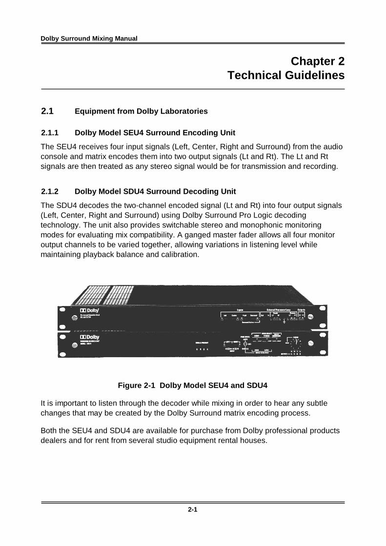
2.1.1 Dolby Model SEU4 Surround Encoding Unit
The SEU4 receives four input signals (Left, Center, Right and Surround) from the audioconsole and matrix encodes them into two output signals (Lt and Rt). The Lt and Rtsignals are then treated as any stereo signal would be for transmission and recording.
2.1.2 Dolby Model SDU4 Surround Decoding Unit
The SDU4 decodes the two-channel encoded signal (Lt and Rt) into four output signals(Left, Center, Right and Surround) using Dolby Surround Pro Logic decodingtechnology. The unit also provides switchable stereo and monophonic monitoringmodes for evaluating mix compatibility. A ganged master fader allows all four monitoroutput channels to be varied together, allowing variations in listening level whilemaintaining playback balance and calibration.
Figure 2-1 Dolby Model SEU4 and SDU4
It is important to listen through the decoder while mixing in order to hear any subtlechanges that may be created by the Dolby Surround matrix encoding process.
Both the SEU4 and SDU4 are available for purchase from Dolby professional productsdealers and for rent from several studio equipment rental houses.
Dolby Surround Mixing Manual Chapter 2 - Technical Guidelines
2-2
2.2 System Information
2.2.1 Room Layouts
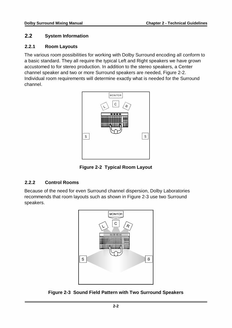
The various room possibilities for working with Dolby Surround encoding all conform toa basic standard. They all require the typical Left and Right speakers we have grownaccustomed to for stereo production. In addition to the stereo speakers, a Centerchannel speaker and two or more Surround speakers are needed, Figure 2-2.Individual room requirements will determine exactly what is needed for the Surroundchannel.
M O N ITO R
RL
SS
C
Figure 2-2 Typical Room Layout
2.2.2 Control Rooms
Because of the need for even Surround channel dispersion, Dolby Laboratoriesrecommends that room layouts such as shown in Figure 2-3 use two Surroundspeakers.
Figure 2-3 Sound Field Pattern with Two Surround Speakers
Dolby Surround Mixing Manual Chapter 2 - Technical Guidelines
2-3
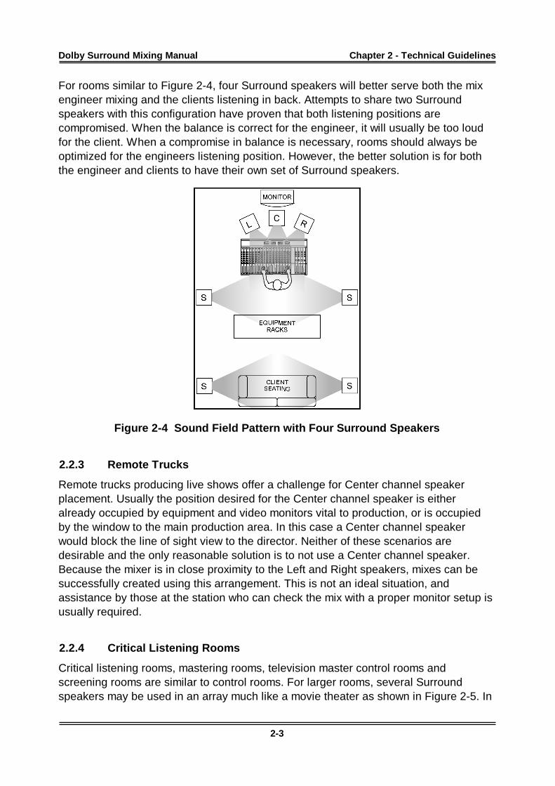
For rooms similar to Figure 2-4, four Surround speakers will better serve both the mixengineer mixing and the clients listening in back. Attempts to share two Surroundspeakers with this configuration have proven that both listening positions arecompromised. When the balance is correct for the engineer, it will usually be too loudfor the client. When a compromise in balance is necessary, rooms should always beoptimized for the engineers listening position. However, the better solution is for boththe engineer and clients to have their own set of Surround speakers.
Figure 2-4 Sound Field Pattern with Four Surround Speakers
2.2.3 Remote Trucks
Remote trucks producing live shows offer a challenge for Center channel speakerplacement. Usually the position desired for the Center channel speaker is eitheralready occupied by equipment and video monitors vital to production, or is occupiedby the window to the main production area. In this case a Center channel speakerwould block the line of sight view to the director. Neither of these scenarios aredesirable and the only reasonable solution is to not use a Center channel speaker.Because the mixer is in close proximity to the Left and Right speakers, mixes can besuccessfully created using this arrangement. This is not an ideal situation, andassistance by those at the station who can check the mix with a proper monitor setup isusually required.
2.2.4 Critical Listening Rooms
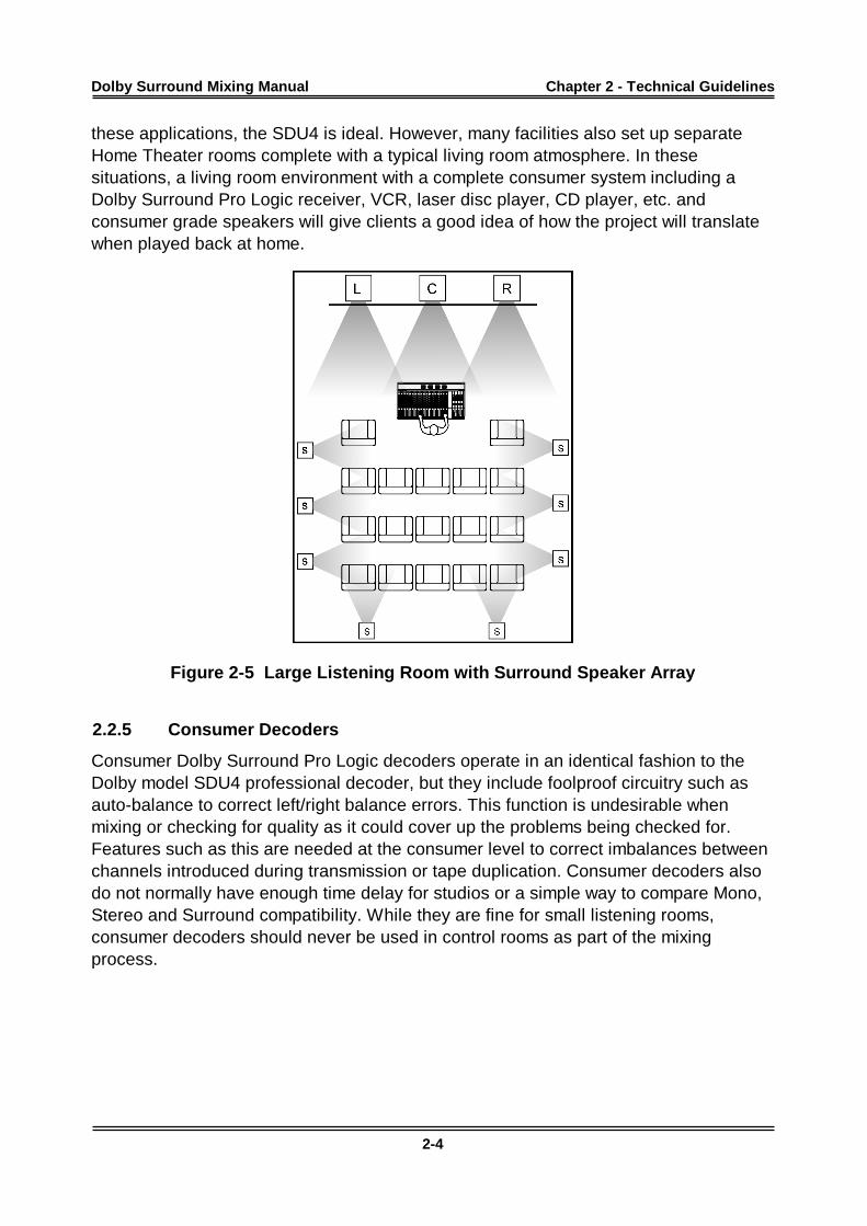
Critical listening rooms, mastering rooms, television master control rooms andscreening rooms are similar to control rooms. For larger rooms, several Surroundspeakers may be used in an array much like a movie theater as shown in Figure 2-5. In
Dolby Surround Mixing Manual Chapter 2 - Technical Guidelines
2-4
these applications, the SDU4 is ideal. However, many facilities also set up separateHome Theater rooms complete with a typical living room atmosphere. In thesesituations, a living room environment with a complete consumer system including aDolby Surround Pro Logic receiver, VCR, laser disc player, CD player, etc. andconsumer grade speakers will give clients a good idea of how the project will translatewhen played back at home.
Figure 2-5 Large Listening Room with Surround Speaker Array
2.2.5 Consumer Decoders
Consumer Dolby Surround Pro Logic decoders operate in an identical fashion to theDolby model SDU4 professional decoder, but they include foolproof circuitry such asauto-balance to correct left/right balance errors. This function is undesirable whenmixing or checking for quality as it could cover up the problems being checked for.Features such as this are needed at the consumer level to correct imbalances betweenchannels introduced during transmission or tape duplication. Consumer decoders alsodo not normally have enough time delay for studios or a simple way to compare Mono,Stereo and Surround compatibility. While they are fine for small listening rooms,consumer decoders should never be used in control rooms as part of the mixingprocess.
Dolby Surround Mixing Manual Chapter 2 - Technical Guidelines
2-5
2.3 Additional Equipment Required
2.3.1 Speakers and Amplifiers
The speaker setup for front speakers may be accomplished two ways. Either add aCenter speaker that matches the acoustic characteristics of the existing Left and Rightsoffit speakers or install three identical near-field monitors. In either case, it is importantthat the design of all three front speakers be identical or panning from one type ofspeaker to the other will cause great differences in the sound. This does not mean thatthey all have to be the same size. It is quite acceptable to use large Left and Rightspeakers and a smaller Center speaker from the same product line. If possible, theCenter speaker should have the same high- and mid-frequency drivers as the Left andRight speakers.
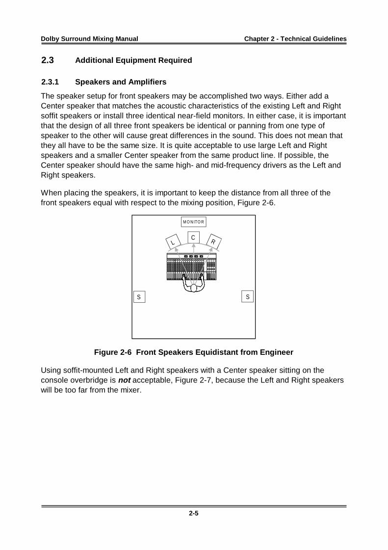
When placing the speakers, it is important to keep the distance from all three of thefront speakers equal with respect to the mixing position, Figure 2-6.
M O N ITO R
RL
SS
C
Figure 2-6 Front Speakers Equidistant from Engineer
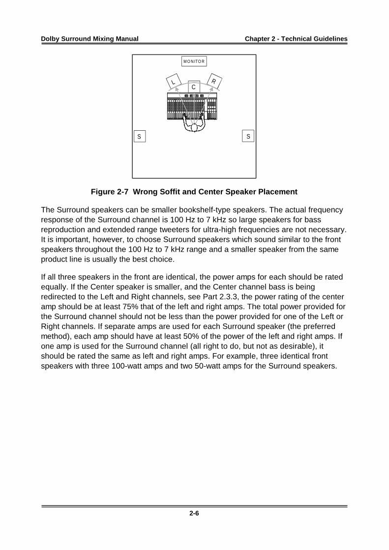
Using soffit-mounted Left and Right speakers with a Center speaker sitting on theconsole overbridge is not acceptable, Figure 2-7, because the Left and Right speakerswill be too far from the mixer.
Dolby Surround Mixing Manual Chapter 2 - Technical Guidelines
2-6
M O N ITO R
RL
SS
C
Figure 2-7 Wrong Soffit and Center Speaker Placement
The Surround speakers can be smaller bookshelf-type speakers. The actual frequencyresponse of the Surround channel is 100 Hz to 7 kHz so large speakers for bassreproduction and extended range tweeters for ultra-high frequencies are not necessary.It is important, however, to choose Surround speakers which sound similar to the frontspeakers throughout the 100 Hz to 7 kHz range and a smaller speaker from the sameproduct line is usually the best choice.
If all three speakers in the front are identical, the power amps for each should be ratedequally. If the Center speaker is smaller, and the Center channel bass is beingredirected to the Left and Right channels, see Part 2.3.3, the power rating of the centeramp should be at least 75% that of the left and right amps. The total power provided forthe Surround channel should not be less than the power provided for one of the Left orRight channels. If separate amps are used for each Surround speaker (the preferredmethod), each amp should have at least 50% of the power of the left and right amps. Ifone amp is used for the Surround channel (all right to do, but not as desirable), itshould be rated the same as left and right amps. For example, three identical frontspeakers with three 100-watt amps and two 50-watt amps for the Surround speakers.
Dolby Surround Mixing Manual Chapter 2 - Technical Guidelines
2-7
2.3.2 Center Channel Speaker
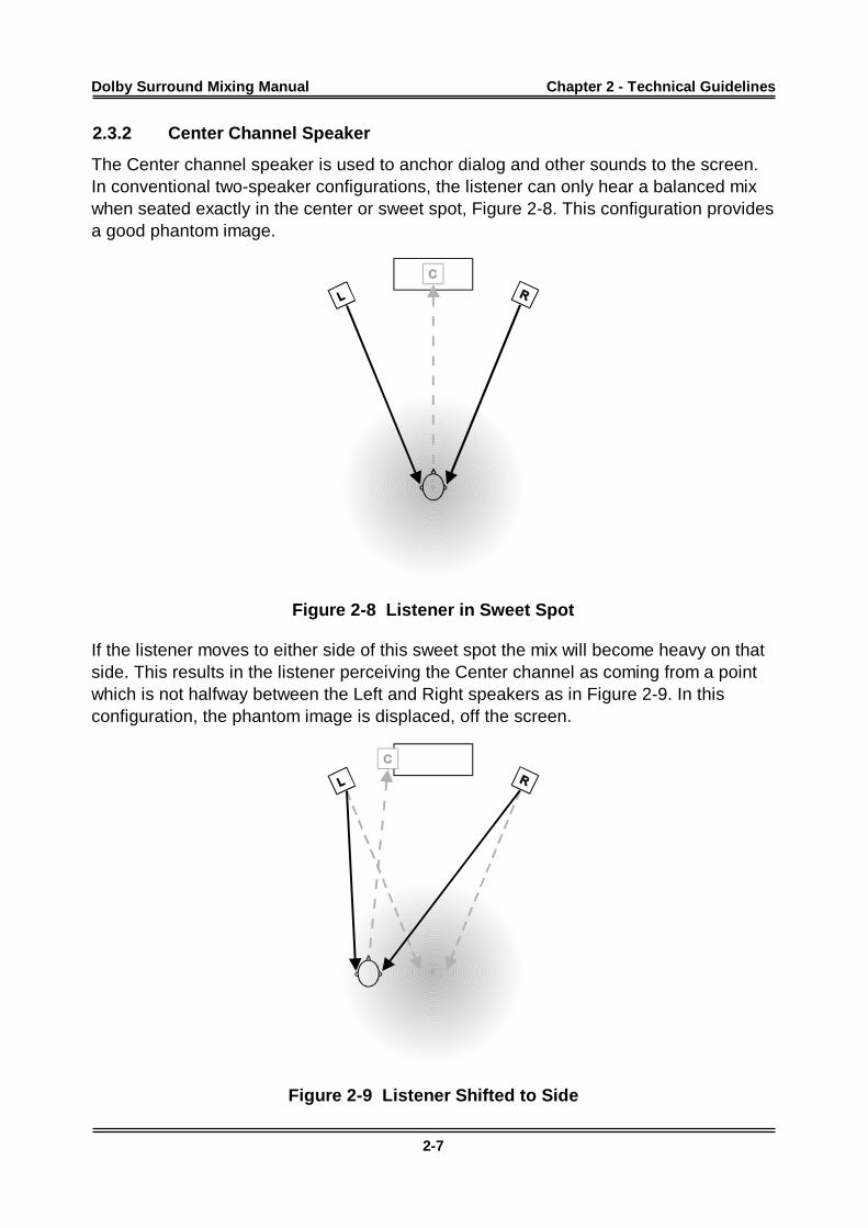
The Center channel speaker is used to anchor dialog and other sounds to the screen.In conventional two-speaker configurations, the listener can only hear a balanced mixwhen seated exactly in the center or sweet spot, Figure 2-8. This configuration providesa good phantom image.
Figure 2-8 Listener in Sweet Spot
If the listener moves to either side of this sweet spot the mix will become heavy on thatside. This results in the listener perceiving the Center channel as coming from a pointwhich is not halfway between the Left and Right speakers as in Figure 2-9. In thisconfiguration, the phantom image is displaced, off the screen.
Figure 2-9 Listener Shifted to Side
Dolby Surround Mixing Manual Chapter 2 - Technical Guidelines
2-8
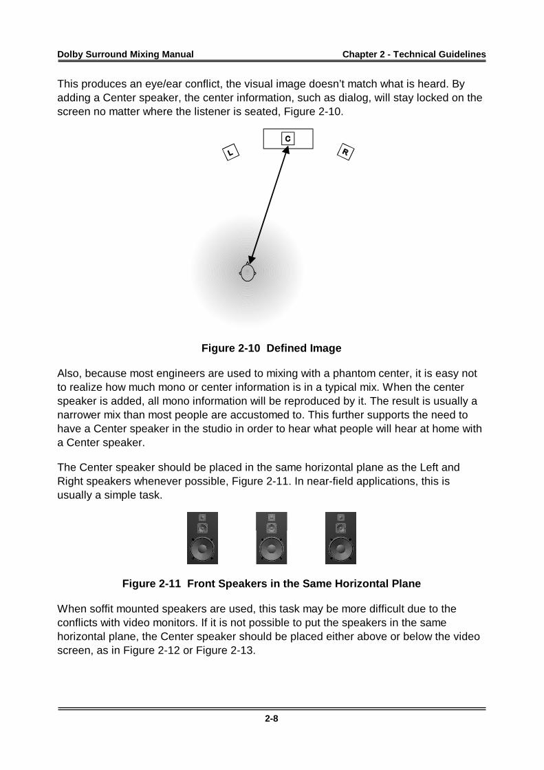
This produces an eye/ear conflict, the visual image doesn’t match what is heard. Byadding a Center speaker, the center information, such as dialog, will stay locked on thescreen no matter where the listener is seated, Figure 2-10.
Figure 2-10 Defined Image
Also, because most engineers are used to mixing with a phantom center, it is easy notto realize how much mono or center information is in a typical mix. When the centerspeaker is added, all mono information will be reproduced by it. The result is usually anarrower mix than most people are accustomed to. This further supports the need tohave a Center speaker in the studio in order to hear what people will hear at home witha Center speaker.
The Center speaker should be placed in the same horizontal plane as the Left andRight speakers whenever possible, Figure 2-11. In near-field applications, this isusually a simple task.
Figure 2-11 Front Speakers in the Same Horizontal Plane
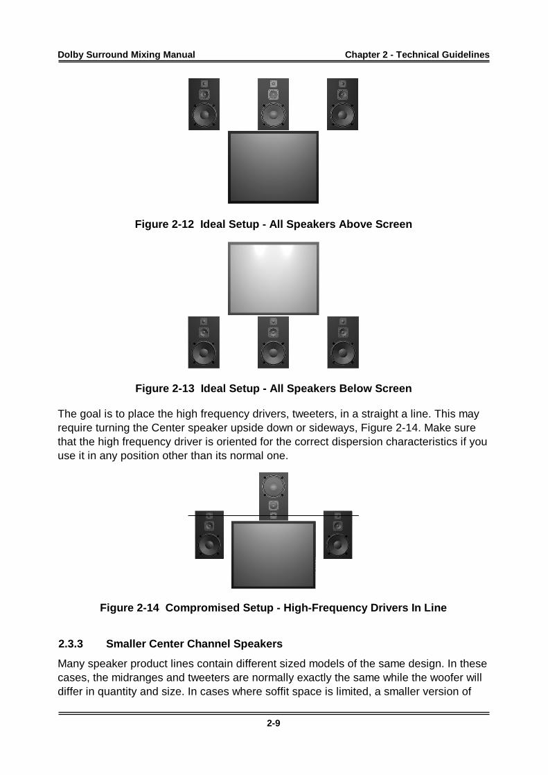
When soffit mounted speakers are used, this task may be more difficult due to theconflicts with video monitors. If it is not possible to put the speakers in the samehorizontal plane, the Center speaker should be placed either above or below the videoscreen, as in Figure 2-12 or Figure 2-13.
Dolby Surround Mixing Manual Chapter 2 - Technical Guidelines
2-9
Figure 2-12 Ideal Setup - All Speakers Above Screen
Figure 2-13 Ideal Setup - All Speakers Below Screen
The goal is to place the high frequency drivers, tweeters, in a straight a line. This mayrequire turning the Center speaker upside down or sideways, Figure 2-14. Make surethat the high frequency driver is oriented for the correct dispersion characteristics if youuse it in any position other than its normal one.
Figure 2-14 Compromised Setup - High-Frequency Drivers In Line
2.3.3 Smaller Center Channel Speakers
Many speaker product lines contain different sized models of the same design. In thesecases, the midranges and tweeters are normally exactly the same while the woofer willdiffer in quantity and size. In cases where soffit space is limited, a smaller version of
Dolby Surround Mixing Manual Chapter 2 - Technical Guidelines
2-10
the main Left and Right speakers may be the only option for the Center channel. TheDolby SDU4 will allow for the smaller Center speaker, with its reduced low frequencycapabilities, by redirecting the Center channel low frequency information below 100 Hzto the Left and Right speakers. For further information on implementing this function,please see Part 3.6.1 Bass Splitting Modification.
2.3.4 Surround Channel Speakers
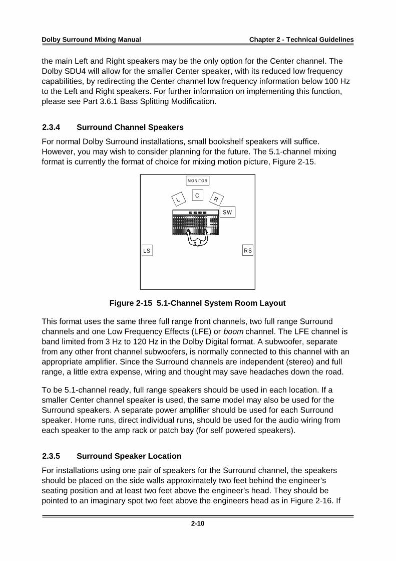
For normal Dolby Surround installations, small bookshelf speakers will suffice.However, you may wish to consider planning for the future. The 5.1-channel mixingformat is currently the format of choice for mixing motion picture, Figure 2-15.
M O N ITO R
RL
RSLS
C
SW
Figure 2-15 5.1-Channel System Room Layout
This format uses the same three full range front channels, two full range Surroundchannels and one Low Frequency Effects (LFE) or boom channel. The LFE channel isband limited from 3 Hz to 120 Hz in the Dolby Digital format. A subwoofer, separatefrom any other front channel subwoofers, is normally connected to this channel with anappropriate amplifier. Since the Surround channels are independent (stereo) and fullrange, a little extra expense, wiring and thought may save headaches down the road.
To be 5.1-channel ready, full range speakers should be used in each location. If asmaller Center channel speaker is used, the same model may also be used for theSurround speakers. A separate power amplifier should be used for each Surroundspeaker. Home runs, direct individual runs, should be used for the audio wiring fromeach speaker to the amp rack or patch bay (for self powered speakers).
2.3.5 Surround Speaker Location
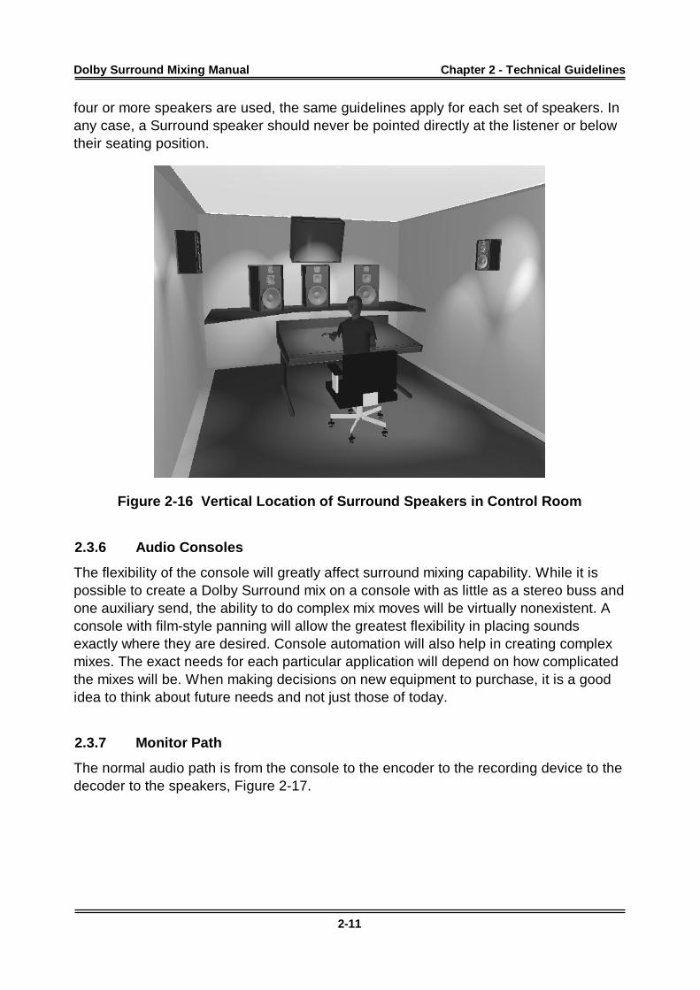
For installations using one pair of speakers for the Surround channel, the speakersshould be placed on the side walls approximately two feet behind the engineer’sseating position and at least two feet above the engineer’s head. They should bepointed to an imaginary spot two feet above the engineers head as in Figure 2-16. If
Dolby Surround Mixing Manual Chapter 2 - Technical Guidelines
2-11
four or more speakers are used, the same guidelines apply for each set of speakers. Inany case, a Surround speaker should never be pointed directly at the listener or belowtheir seating position.
Figure 2-16 Vertical Location of Surround Speakers in Control Room
2.3.6 Audio Consoles
The flexibility of the console will greatly affect surround mixing capability. While it ispossible to create a Dolby Surround mix on a console with as little as a stereo buss andone auxiliary send, the ability to do complex mix moves will be virtually nonexistent. Aconsole with film-style panning will allow the greatest flexibility in placing soundsexactly where they are desired. Console automation will also help in creating complexmixes. The exact needs for each particular application will depend on how complicatedthe mixes will be. When making decisions on new equipment to purchase, it is a goodidea to think about future needs and not just those of today.
2.3.7 Monitor Path
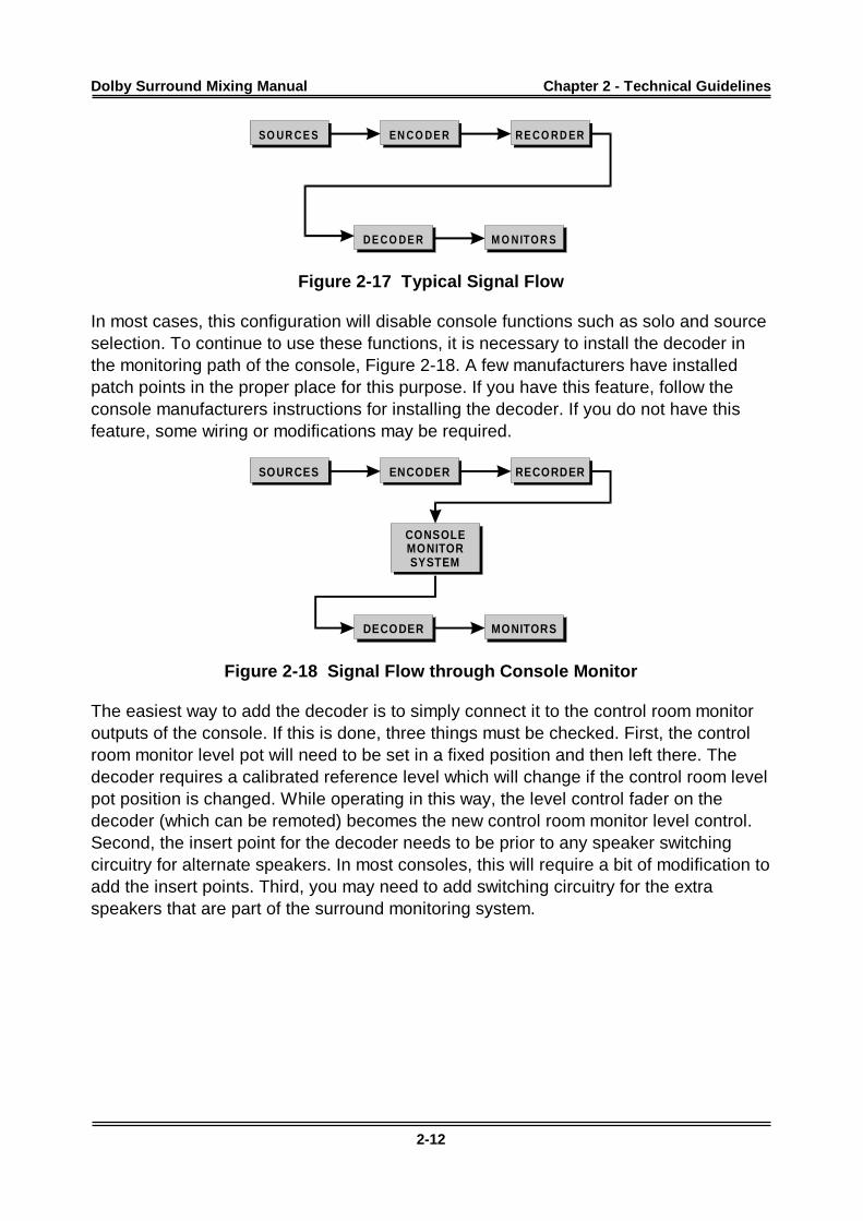
The normal audio path is from the console to the encoder to the recording device to thedecoder to the speakers, Figure 2-17.
Dolby Surround Mixing Manual Chapter 2 - Technical Guidelines
2-12
D E C O D E R M O N ITO R S
SO U R C E S EN C O D E R R E C O R D ER
Figure 2-17 Typical Signal Flow
In most cases, this configuration will disable console functions such as solo and sourceselection. To continue to use these functions, it is necessary to install the decoder inthe monitoring path of the console, Figure 2-18. A few manufacturers have installedpatch points in the proper place for this purpose. If you have this feature, follow theconsole manufacturers instructions for installing the decoder. If you do not have thisfeature, some wiring or modifications may be required.
DECODER
CONSOLEMONITORSYSTEM
MONITORS
SOURCES ENCODER RECORDER
Figure 2-18 Signal Flow through Console Monitor
The easiest way to add the decoder is to simply connect it to the control room monitoroutputs of the console. If this is done, three things must be checked. First, the controlroom monitor level pot will need to be set in a fixed position and then left there. Thedecoder requires a calibrated reference level which will change if the control room levelpot position is changed. While operating in this way, the level control fader on thedecoder (which can be remoted) becomes the new control room monitor level control.Second, the insert point for the decoder needs to be prior to any speaker switchingcircuitry for alternate speakers. In most consoles, this will require a bit of modification toadd the insert points. Third, you may need to add switching circuitry for the extraspeakers that are part of the surround monitoring system.
Dolby Surround Mixing Manual Chapter 2 - Technical Guidelines
2-13
FROMBUSS
OUTP UT
FROMBUSS
OUTP UT
FROMBUSS
OUTP UT
FROMBUSS
OUTP UT
TO MAINM ONITORAMPS
TO MAINM ONITORAMPS
TO MAINM ONITORAMPS
TO MAINM ONITORAMPS
FROMM ACHIN E
OUTP UT
FROMM ACHIN E
OUTP UT
FROMM ACHIN E
OUTP UT
FROMM ACHIN E
OUTP UT
FROMSDU4
OUTP UT
FROMSDU4
OUTP UT
FROMSDU4
OUTP UT
FROMSDU4
OUTP UT
C
R
S
L
2
3
4
1
C
R
S
L
C
R
S
L
TO “B”M ONITORAMPS
TO “B”M ONITORAMPS
TO “B”M ONITORAMPS
TO “B”M ONITORAMPS
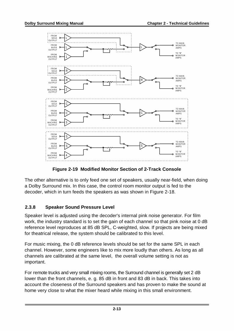
Figure 2-19 Modified Monitor Section of 2-Track Console
The other alternative is to only feed one set of speakers, usually near-field, when doinga Dolby Surround mix. In this case, the control room monitor output is fed to thedecoder, which in turn feeds the speakers as was shown in Figure 2-18.
2.3.8 Speaker Sound Pressure Level
Speaker level is adjusted using the decoder's internal pink noise generator. For filmwork, the industry standard is to set the gain of each channel so that pink noise at 0 dBreference level reproduces at 85 dB SPL, C-weighted, slow. If projects are being mixedfor theatrical release, the system should be calibrated to this level.
For music mixing, the 0 dB reference levels should be set for the same SPL in eachchannel. However, some engineers like to mix more loudly than others. As long as allchannels are calibrated at the same level, the overall volume setting is not asimportant.
For remote trucks and very small mixing rooms, the Surround channel is generally set 2 dBlower than the front channels, e. g. 85 dB in front and 83 dB in back. This takes intoaccount the closeness of the Surround speakers and has proven to make the sound athome very close to what the mixer heard while mixing in this small environment.
Dolby Surround Mixing Manual Chapter 2 - Technical Guidelines
2-14
For home video releases the 0 dB reference level is usually set to 79 dB. This lowerlevel is used to ensure that dialog will not be lost in a typical, somewhat noisy, homeenvironment.
2.3.9 SPL Meters
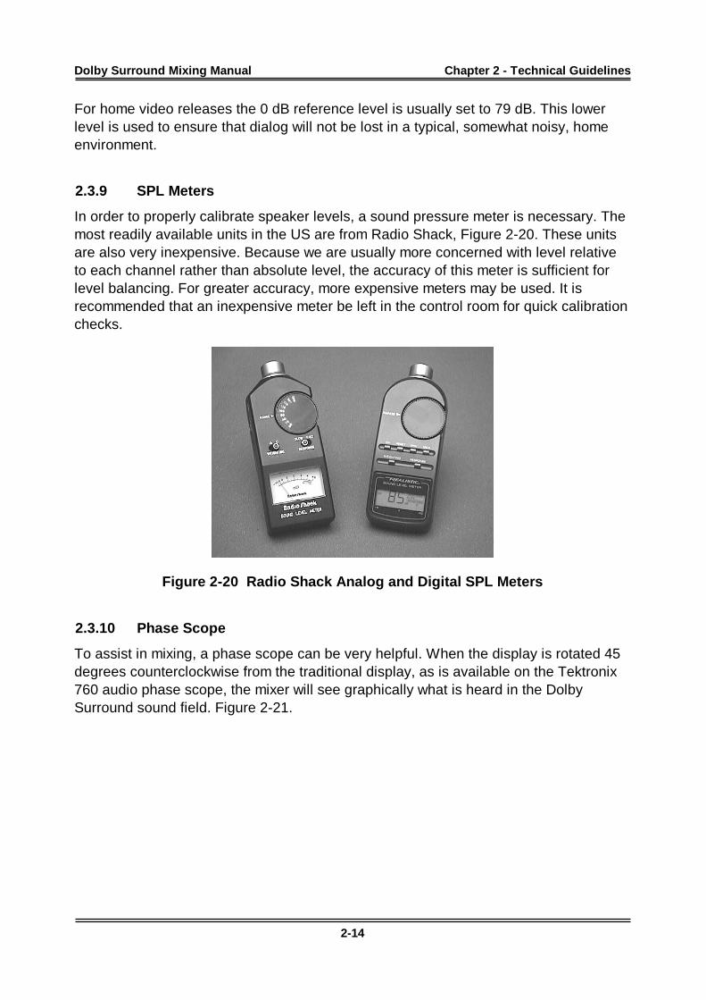
In order to properly calibrate speaker levels, a sound pressure meter is necessary. Themost readily available units in the US are from Radio Shack, Figure 2-20. These unitsare also very inexpensive. Because we are usually more concerned with level relativeto each channel rather than absolute level, the accuracy of this meter is sufficient forlevel balancing. For greater accuracy, more expensive meters may be used. It isrecommended that an inexpensive meter be left in the control room for quick calibrationchecks.
Figure 2-20 Radio Shack Analog and Digital SPL Meters
2.3.10 Phase Scope
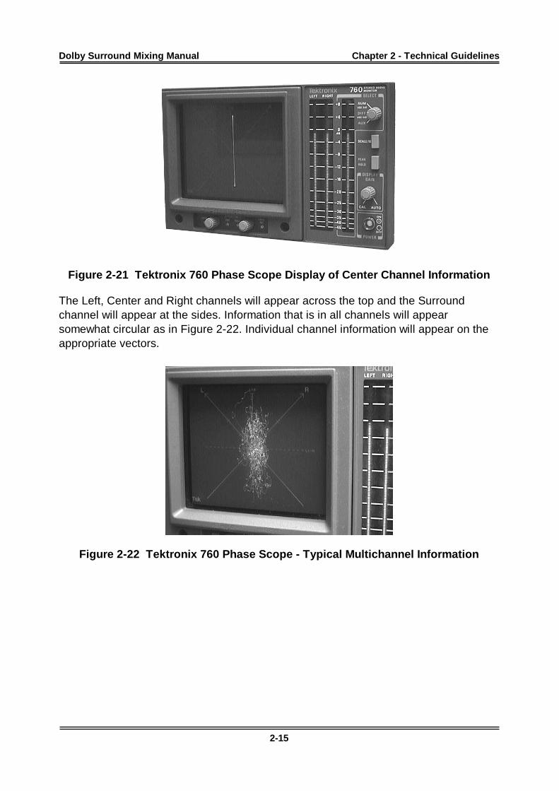
To assist in mixing, a phase scope can be very helpful. When the display is rotated 45degrees counterclockwise from the traditional display, as is available on the Tektronix760 audio phase scope, the mixer will see graphically what is heard in the DolbySurround sound field. Figure 2-21.
Dolby Surround Mixing Manual Chapter 2 - Technical Guidelines
2-15
Figure 2-21 Tektronix 760 Phase Scope Display of Center Channel Information
The Left, Center and Right channels will appear across the top and the Surroundchannel will appear at the sides. Information that is in all channels will appearsomewhat circular as in Figure 2-22. Individual channel information will appear on theappropriate vectors.
Figure 2-22 Tektronix 760 Phase Scope - Typical Multichannel Information
Dolby Surround Mixing Manual
3-1
Chapter 3System Installation
3.1 Signal Routing Audio Connections
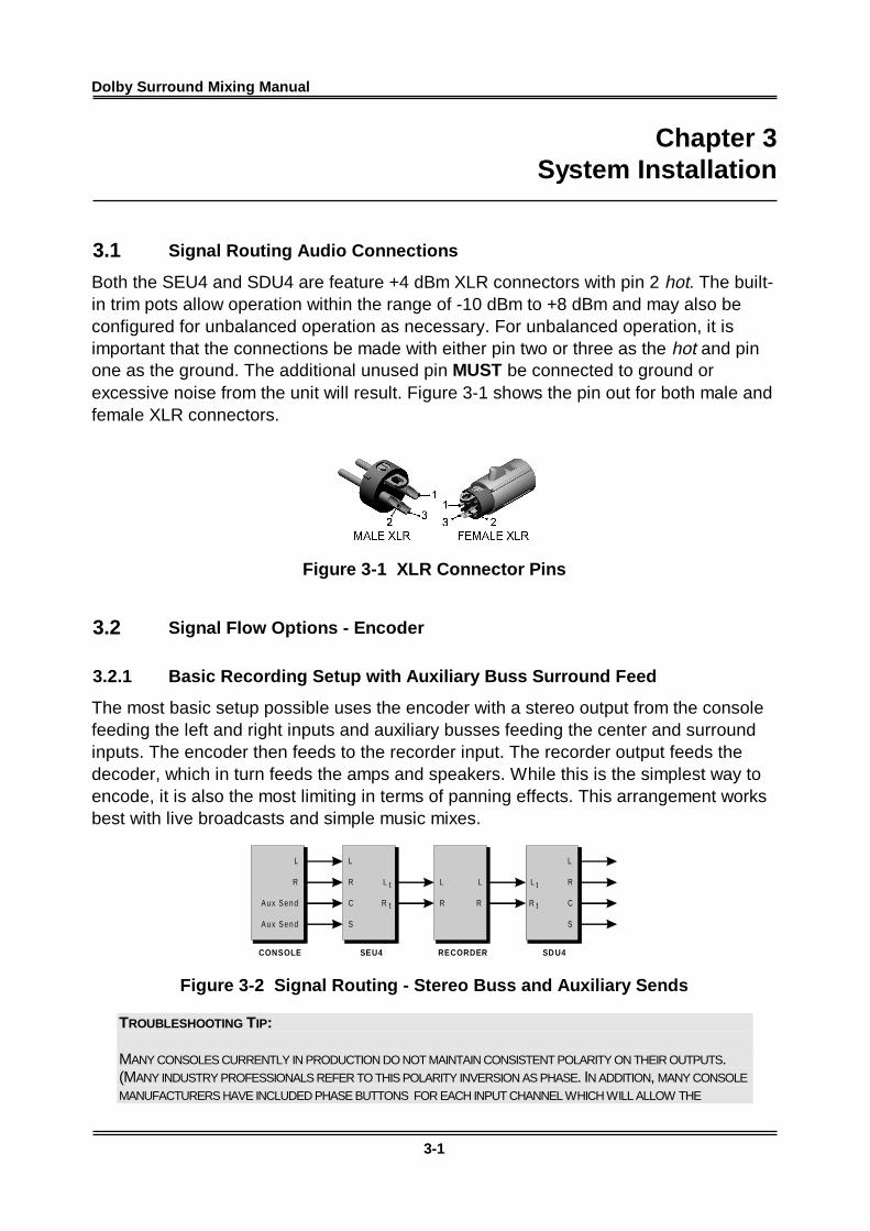
Both the SEU4 and SDU4 are feature +4 dBm XLR connectors with pin 2 hot. The built-in trim pots allow operation within the range of -10 dBm to +8 dBm and may also beconfigured for unbalanced operation as necessary. For unbalanced operation, it isimportant that the connections be made with either pin two or three as the hot and pinone as the ground. The additional unused pin MUST be connected to ground orexcessive noise from the unit will result. Figure 3-1 shows the pin out for both male andfemale XLR connectors.
Figure 3-1 XLR Connector Pins
3.2 Signal Flow Options - Encoder
3.2.1 Basic Recording Setup with Auxiliary Buss Surround Feed
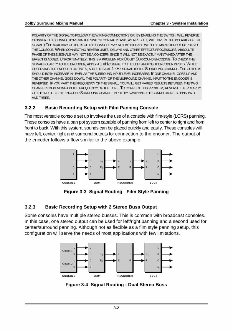
The most basic setup possible uses the encoder with a stereo output from the consolefeeding the left and right inputs and auxiliary busses feeding the center and surroundinputs. The encoder then feeds to the recorder input. The recorder output feeds thedecoder, which in turn feeds the amps and speakers. While this is the simplest way toencode, it is also the most limiting in terms of panning effects. This arrangement worksbest with live broadcasts and simple music mixes.
CONSOLE SEU4 RECORDER SD U4
L
LR
RAu x Se n d
Au x Se n d
L L
LR R
RC C
S S
L L
R R
t t
t t
Figure 3-2 Signal Routing - Stereo Buss and Auxiliary Sends
TROUBLESHOOTING TIP:
MANY CONSOLES CURRENTLY IN PRODUCTION DO NOT MAINTAIN CONSISTENT POLARITY ON THEIR OUTPUTS.(MANY INDUSTRY PROFESSIONALS REFER TO THIS POLARITY INVERSION AS PHASE. IN ADDITION, MANY CONSOLE
MANUFACTURERS HAVE INCLUDED PHASE BUTTONS FOR EACH INPUT CHANNEL WHICH WILL ALLOW THE
Dolby Surround Mixing Manual Chapter 3 - System Installation
3-2
POLARITY OF THE SIGNAL TO FOLLOW THE WIRING CONNECTIONS OR, BY ENABLING THE SWITCH, WILL REVERSE
OR INVERT THE CONNECTIONS VIA THE SWITCH CONTACTS AND, AS A RESULT, WILL INVERT THE POLARITY OF THE
SIGNAL.) THE AUXILIARY OUTPUTS OF THE CONSOLE MAY NOT BE IN PHASE WITH THE MAIN STEREO OUTPUTS OF
THE CONSOLE. WHEN CONNECTING REVERB UNITS, DELAYS AND OTHER EFFECTS PROCESSORS, ABSOLUTE
PHASE OF THESE SIGNALS MAY NOT BE A CONCERN SINCE IT WILL NOT BE EXACTLY MAINTAINED AFTER THE
EFFECT IS ADDED. UNFORTUNATELY, THIS IS A PROBLEM FOR DOLBY SURROUND ENCODING. TO CHECK THE
SIGNAL POLARITY TO THE ENCODER, APPLY A 1 KHZ SIGNAL TO THE LEFT AND RIGHT ENCODER INPUTS. WHILE
OBSERVING THE ENCODER OUTPUTS, ADD THE SAME 1 KHZ SIGNAL TO THE SURROUND CHANNEL. THE OUTPUTS
SHOULD BOTH INCREASE IN LEVEL AS THE SURROUND INPUT LEVEL INCREASES. IF ONE CHANNEL GOES UP AND
THE OTHER CHANNEL GOES DOWN, THE POLARITY OF THE SURROUND CHANNEL INPUT TO THE ENCODER IS
REVERSED. IF YOU VARY THE FREQUENCY OF THE SIGNAL, YOU WILL GET VARIED RESULTS BETWEEN THE TWO
CHANNELS DEPENDING ON THE FREQUENCY OF THE TONE. TO CORRECT THIS PROBLEM, REVERSE THE POLARITY
OF THE INPUT TO THE ENCODER SURROUND CHANNEL INPUT BY SWAPPING THE CONNECTIONS TO PINS TWO
AND THREE.
3.2.2 Basic Recording Setup with Film Panning Console
The most versatile console set up involves the use of a console with film-style (LCRS) panning.These consoles have a pan pot system capable of panning from left to center to right and fromfront to back. With this system, sounds can be placed quickly and easily. These consoles willhave left, center, right and surround outputs for connection to the encoder. The output ofthe encoder follows a flow similar to the above example.
CONSOLE SEU4 RECO RDER SDU4
L
LR
RC
S
L L
LR R
RC C
S S
L L
R R
t t
t t
Figure 3-3 Signal Routing - Film-Style Panning
3.2.3 Basic Recording Setup with 2 Stereo Buss Output
Some consoles have multiple stereo busses. This is common with broadcast consoles.In this case, one stereo output can be used for left/right panning and a second used forcenter/surround panning. Although not as flexible as a film style panning setup, thisconfiguration will serve the needs of most applications with few limitations.
CONSOLE SEU4 RECO RDER SDU4
L
L
LR
R
R
L L
LR R
RC C
S S
O utput 1
O utput 2
L L
R R
t t
t t
Figure 3-4 Signal Routing - Dual Stereo Buss
Dolby Surround Mixing Manual Chapter 3 - System Installation
3-3
3.3 Signal Flow Options - Decoder
3.3.1 Recording Setup with Monitor Section of Console
All of the above connections involve feeds to the encoder. They assume a signal pathfrom the encoder output to the recording device. The recording device then feeds thedecoder that in turn feeds the amps and speakers.
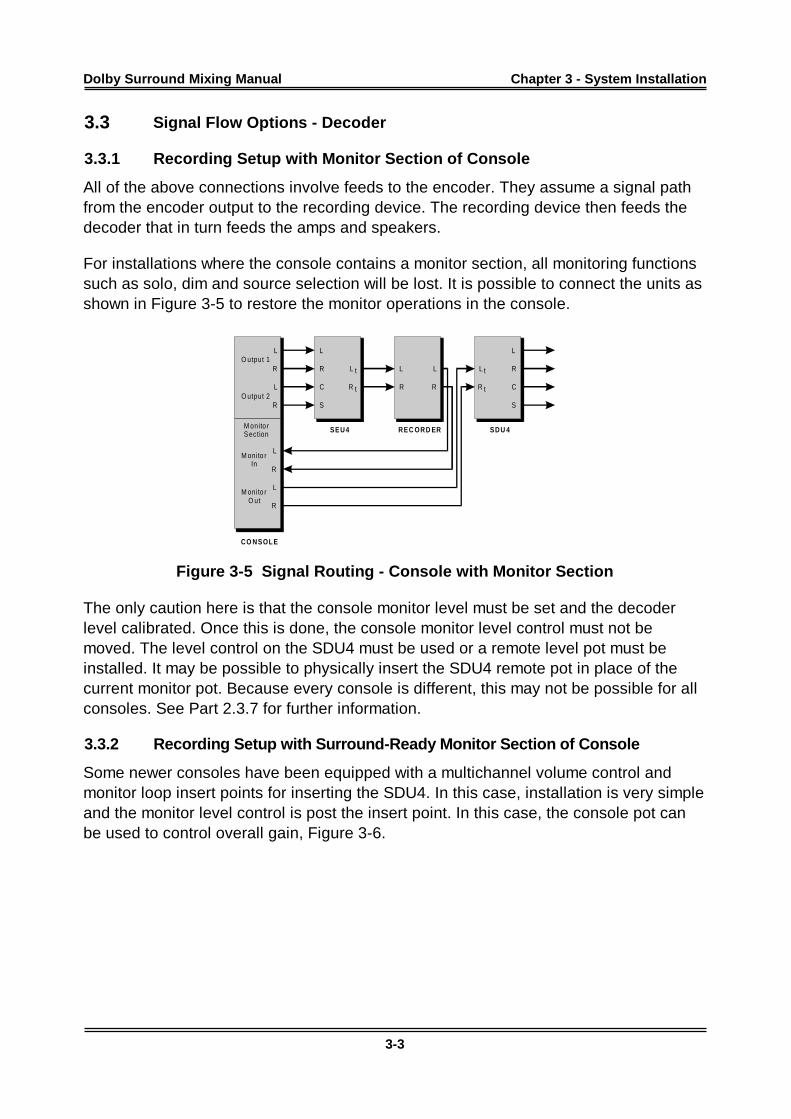
For installations where the console contains a monitor section, all monitoring functionssuch as solo, dim and source selection will be lost. It is possible to connect the units asshown in Figure 3-5 to restore the monitor operations in the console.
CO NSOL E
SEU4 REC ORD ER SDU 4
L
L
L
L
LR
R
R
R
R
L L
R R
L L
LR R
RC C
S S
O utput 1
M onito rO ut
M onito rIn
O utput 2
M onito rSection
t t
t t
Figure 3-5 Signal Routing - Console with Monitor Section
The only caution here is that the console monitor level must be set and the decoderlevel calibrated. Once this is done, the console monitor level control must not bemoved. The level control on the SDU4 must be used or a remote level pot must beinstalled. It may be possible to physically insert the SDU4 remote pot in place of thecurrent monitor pot. Because every console is different, this may not be possible for allconsoles. See Part 2.3.7 for further information.
3.3.2 Recording Setup with Surround-Ready Monitor Section of Console
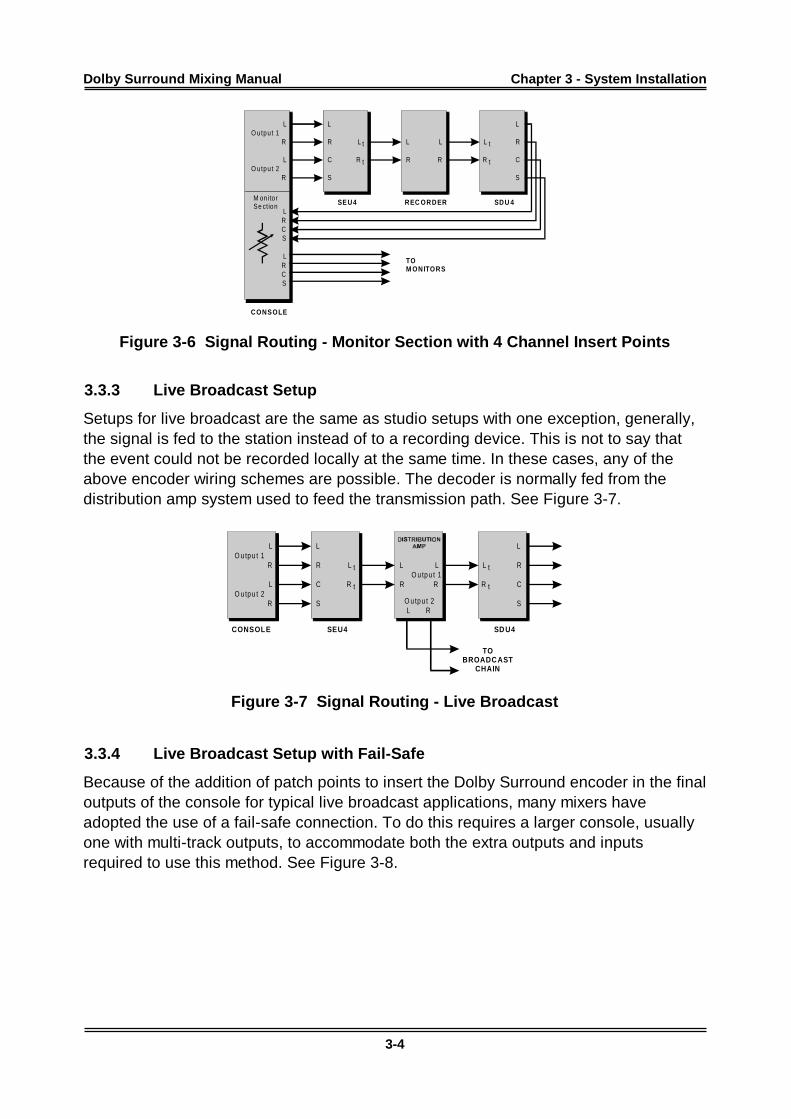
Some newer consoles have been equipped with a multichannel volume control andmonitor loop insert points for inserting the SDU4. In this case, installation is very simpleand the monitor level control is post the insert point. In this case, the console pot canbe used to control overall gain, Figure 3-6.
Dolby Surround Mixing Manual Chapter 3 - System Installation
3-4
CONSOLE
SEU4 REC ORDER SDU 4
L
L
C
C
LR
R
R
L
L
R
S
S
R
L L
R R
L L
LR R
RC C
S S
O utpu t 1
O utpu t 2
M on ito rSe ction
t t
t t
TOM ONITORS
Figure 3-6 Signal Routing - Monitor Section with 4 Channel Insert Points
3.3.3 Live Broadcast Setup
Setups for live broadcast are the same as studio setups with one exception, generally,the signal is fed to the station instead of to a recording device. This is not to say thatthe event could not be recorded locally at the same time. In these cases, any of theabove encoder wiring schemes are possible. The decoder is normally fed from thedistribution amp system used to feed the transmission path. See Figure 3-7.
CONSOLE SEU4 SD U4
L
L
LR
R
R
L L
R R
L L
LR R
RC C
S S
O u tp u t 1
O u tp u t 1
O u tp u t 2O u tp u t 2
t t
t t
L R
TOBROADC AST
CHAIN
Figure 3-7 Signal Routing - Live Broadcast
3.3.4 Live Broadcast Setup with Fail-Safe
Because of the addition of patch points to insert the Dolby Surround encoder in the finaloutputs of the console for typical live broadcast applications, many mixers haveadopted the use of a fail-safe connection. To do this requires a larger console, usuallyone with multi-track outputs, to accommodate both the extra outputs and inputsrequired to use this method. See Figure 3-8.
Dolby Surround Mixing Manual Chapter 3 - System Installation
3-5
CONSOLE
SEU4
SDU4
1
L
3
L
2
R
4
R
L
L
R
RL
L
R
R
C
C
S
S
BUSS
ASSI
GNS
INPUT
MODULES
M a inO u tpu t
t
t
t
t
L
R
L
RO u tpu t 1
O u tpu t 2L R
TOBROADC AST
CHAIN
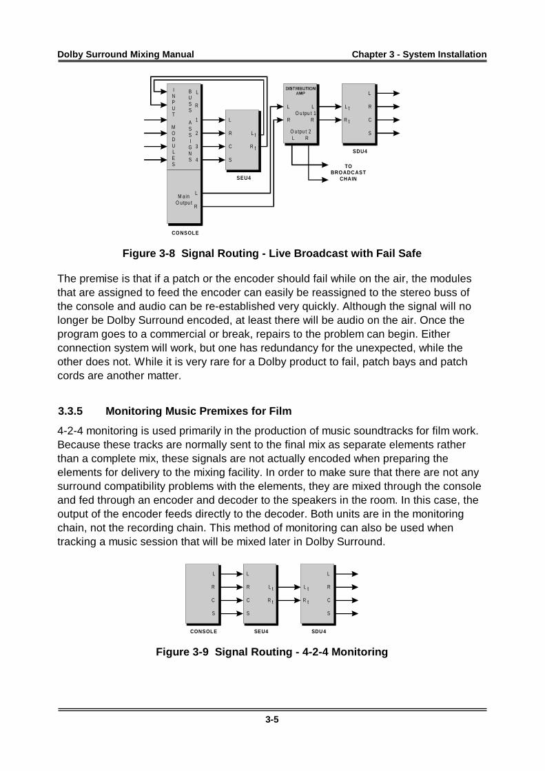
Figure 3-8 Signal Routing - Live Broadcast with Fail Safe
The premise is that if a patch or the encoder should fail while on the air, the modulesthat are assigned to feed the encoder can easily be reassigned to the stereo buss ofthe console and audio can be re-established very quickly. Although the signal will nolonger be Dolby Surround encoded, at least there will be audio on the air. Once theprogram goes to a commercial or break, repairs to the problem can begin. Eitherconnection system will work, but one has redundancy for the unexpected, while theother does not. While it is very rare for a Dolby product to fail, patch bays and patchcords are another matter.
3.3.5 Monitoring Music Premixes for Film
4-2-4 monitoring is used primarily in the production of music soundtracks for film work.Because these tracks are normally sent to the final mix as separate elements ratherthan a complete mix, these signals are not actually encoded when preparing theelements for delivery to the mixing facility. In order to make sure that there are not anysurround compatibility problems with the elements, they are mixed through the consoleand fed through an encoder and decoder to the speakers in the room. In this case, theoutput of the encoder feeds directly to the decoder. Both units are in the monitoringchain, not the recording chain. This method of monitoring can also be used whentracking a music session that will be mixed later in Dolby Surround.
CONSOLE SEU4 SDU 4
L
R
C
S
L L
R R
C C
S S
L L
R R
t t
t t
Figure 3-9 Signal Routing - 4-2-4 Monitoring
Dolby Surround Mixing Manual Chapter 3 - System Installation
3-6
3.4 Dolby Model SEU4 Setup
Normal operation of the SEU4 requires no modifications to the unit as it comes from thefactory. There are two modes which should be checked if problems are encountered.
3.4.1 Surround Active LED
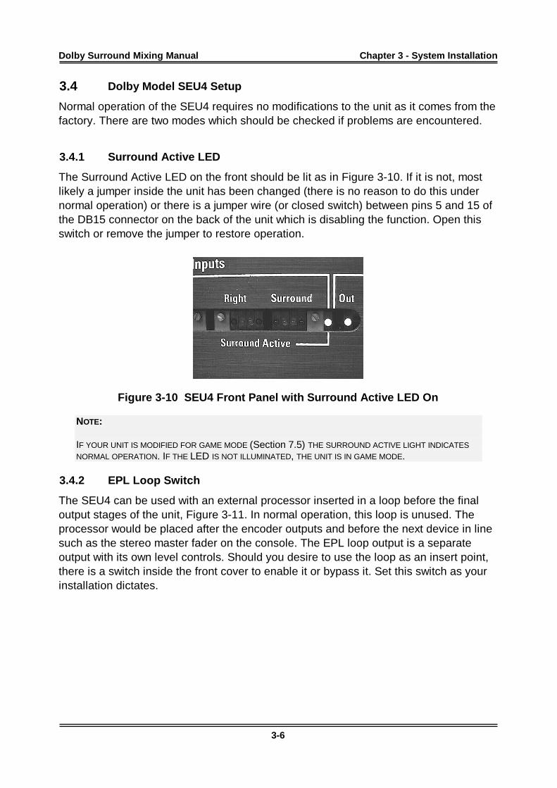
The Surround Active LED on the front should be lit as in Figure 3-10. If it is not, mostlikely a jumper inside the unit has been changed (there is no reason to do this undernormal operation) or there is a jumper wire (or closed switch) between pins 5 and 15 ofthe DB15 connector on the back of the unit which is disabling the function. Open thisswitch or remove the jumper to restore operation.
Figure 3-10 SEU4 Front Panel with Surround Active LED On
NOTE:
IF YOUR UNIT IS MODIFIED FOR GAME MODE (Section 7.5) THE SURROUND ACTIVE LIGHT INDICATES
NORMAL OPERATION. IF THE LED IS NOT ILLUMINATED, THE UNIT IS IN GAME MODE.
3.4.2 EPL Loop Switch
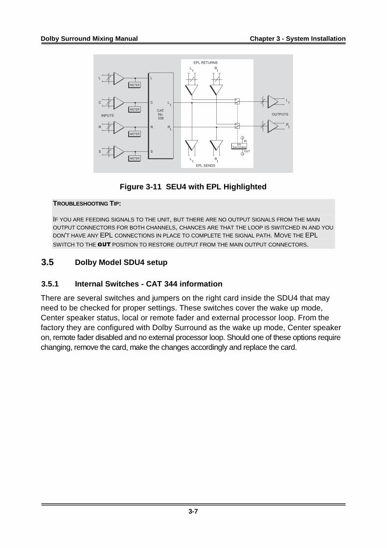
The SEU4 can be used with an external processor inserted in a loop before the finaloutput stages of the unit, Figure 3-11. In normal operation, this loop is unused. Theprocessor would be placed after the encoder outputs and before the next device in linesuch as the stereo master fader on the console. The EPL loop output is a separateoutput with its own level controls. Should you desire to use the loop as an insert point,there is a switch inside the front cover to enable it or bypass it. Set this switch as yourinstallation dictates.
Dolby Surround Mixing Manual Chapter 3 - System Installation
3-7
METER
EPL
SWITCHING
METER
METER
METER
L L
C C Lt
Lt
Lt
Lt
R R Rt
Rt
Rt
Rt
S S
R
G
IN
OUT
EPL RETURNS
EPL SENDS
OUTPUTSINPUTS
CAT.
No.
338
METER
EPL
SWITCHING
METER
METER
METER
L L
C C Lt
Lt
Lt
Lt
R R Rt
Rt
Rt
Rt
S S
R
G
IN
OUT
EPL RETURNS
EPL SENDS
OUTPUTSINPUTS
CAT.
No.
338
Figure 3-11 SEU4 with EPL Highlighted
TROUBLESHOOTING TIP:
IF YOU ARE FEEDING SIGNALS TO THE UNIT, BUT THERE ARE NO OUTPUT SIGNALS FROM THE MAIN
OUTPUT CONNECTORS FOR BOTH CHANNELS, CHANCES ARE THAT THE LOOP IS SWITCHED IN AND YOU
DON'T HAVE ANY EPL CONNECTIONS IN PLACE TO COMPLETE THE SIGNAL PATH. MOVE THE EPLSWITCH TO THE 287 POSITION TO RESTORE OUTPUT FROM THE MAIN OUTPUT CONNECTORS.
3.5 Dolby Model SDU4 setup
3.5.1 Internal Switches - CAT 344 information
There are several switches and jumpers on the right card inside the SDU4 that mayneed to be checked for proper settings. These switches cover the wake up mode,Center speaker status, local or remote fader and external processor loop. From thefactory they are configured with Dolby Surround as the wake up mode, Center speakeron, remote fader disabled and no external processor loop. Should one of these options requirechanging, remove the card, make the changes accordingly and replace the card.
Dolby Surround Mixing Manual Chapter 3 - System Installation
3-8
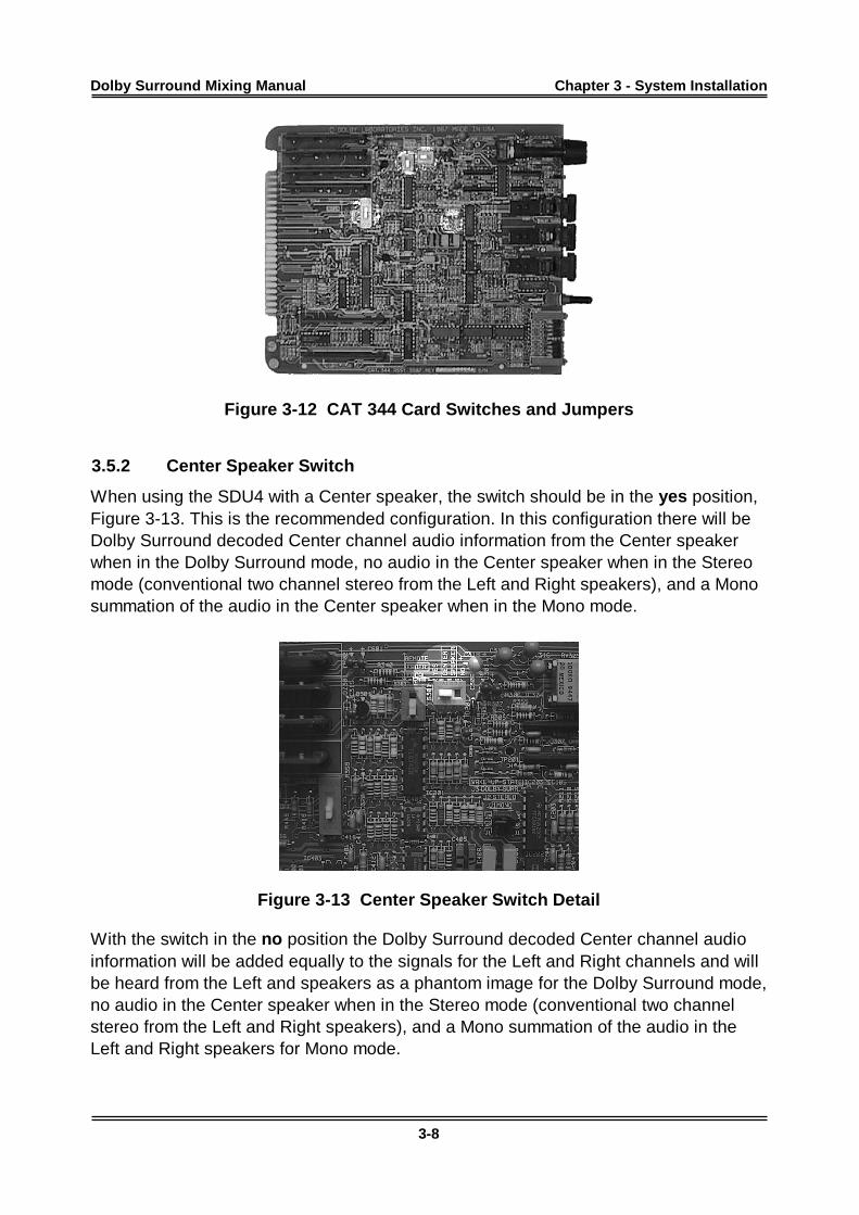
Figure 3-12 CAT 344 Card Switches and Jumpers
3.5.2 Center Speaker Switch
When using the SDU4 with a Center speaker, the switch should be in the yes position,Figure 3-13. This is the recommended configuration. In this configuration there will beDolby Surround decoded Center channel audio information from the Center speakerwhen in the Dolby Surround mode, no audio in the Center speaker when in the Stereomode (conventional two channel stereo from the Left and Right speakers), and a Monosummation of the audio in the Center speaker when in the Mono mode.
Figure 3-13 Center Speaker Switch Detail
With the switch in the no position the Dolby Surround decoded Center channel audioinformation will be added equally to the signals for the Left and Right channels and willbe heard from the Left and speakers as a phantom image for the Dolby Surround mode,no audio in the Center speaker when in the Stereo mode (conventional two channelstereo from the Left and Right speakers), and a Mono summation of the audio in theLeft and Right speakers for Mono mode.
Dolby Surround Mixing Manual Chapter 3 - System Installation
3-9
TROUBLESHOOTING TIP:
IF A CENTER SPEAKER IS NOT BEING USED AND LEFT AND RIGHT INFORMATION CAN BE HEARD, BUT NO
CENTER INFORMATION WHEN IN EITHER THE DOLBY SURROUND MODE OR MONO MODE, THE CENTER
SPEAKER SWITCH IS PROBABLY SET TO THE YES POSITION. THIS RESULTS IN ALL OF THE CENTER
INFORMATION BEING FED TO THE CENTER OUTPUT OF THE DECODER (WHICH, IN THIS CASE, IS AN
OPEN UNCONNECTED OUTPUT). TO CORRECT THIS, REMOVE THE CARD AND MOVE THE CENTER
SPEAKER SWITCH TO THE NO POSITION OR ADD A CENTER SPEAKER AND AMPLIFIER.
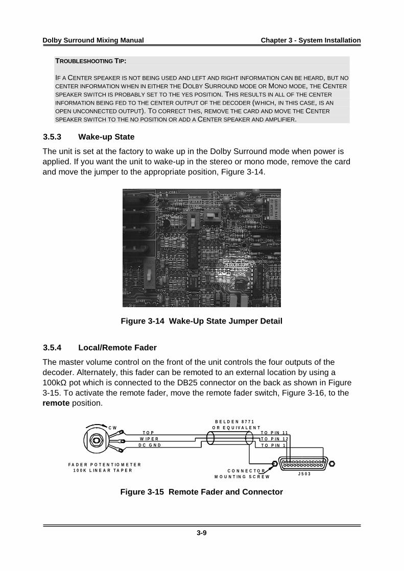
3.5.3 Wake-up State
The unit is set at the factory to wake up in the Dolby Surround mode when power isapplied. If you want the unit to wake-up in the stereo or mono mode, remove the cardand move the jumper to the appropriate position, Figure 3-14.
Figure 3-14 Wake-Up State Jumper Detail
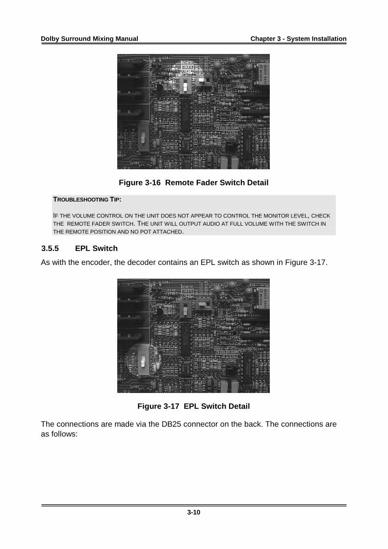
3.5.4 Local/Remote Fader
The master volume control on the front of the unit controls the four outputs of thedecoder. Alternately, this fader can be remoted to an external location by using a100kΩ pot which is connected to the DB25 connector on the back as shown in Figure3-15. To activate the remote fader, move the remote fader switch, Figure 3-16, to theremote position.
1 3 1
J 5 0 3
T O P I N 1T O P I N 1 2T O P I N 1 1
D C G N DW I P E R
T O P
M O U N T I N G S C R E WC O N N E C T O R
O R E Q U I V A L E N TB E L D E N 8 7 7 1
1 0 0 K L I N E A R T A P E R
C W
F A D E R P O T E N T I O M E T E R
Figure 3-15 Remote Fader and Connector
Dolby Surround Mixing Manual Chapter 3 - System Installation
3-10
Figure 3-16 Remote Fader Switch Detail
TROUBLESHOOTING TIP:
IF THE VOLUME CONTROL ON THE UNIT DOES NOT APPEAR TO CONTROL THE MONITOR LEVEL, CHECK
THE REMOTE FADER SWITCH. THE UNIT WILL OUTPUT AUDIO AT FULL VOLUME WITH THE SWITCH IN
THE REMOTE POSITION AND NO POT ATTACHED.
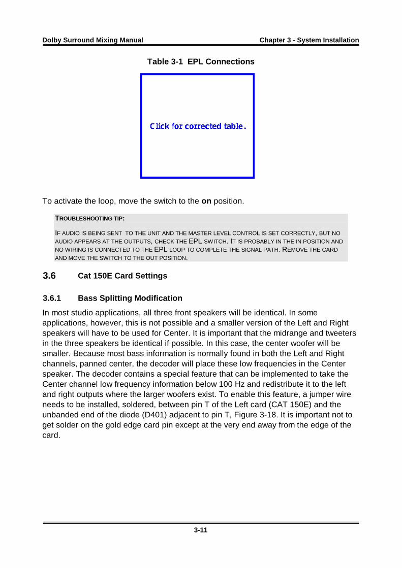
3.5.5 EPL Switch
As with the encoder, the decoder contains an EPL switch as shown in Figure 3-17.
Figure 3-17 EPL Switch Detail
The connections are made via the DB25 connector on the back. The connections areas follows:
Dolby Surround Mixing Manual Chapter 3 - System Installation
3-11
Table 3-1 EPL Connections
Pin Signal17 Loop Send Left16 Loop Send Center15 Loop Send Right14 Loop Send Surround5 Loop Return Left4 Loop Return Center3 Loop Return Right2 Loop Return Surround1 Ground
To activate the loop, move the switch to the on position.
TROUBLESHOOTING TIP:
IF AUDIO IS BEING SENT TO THE UNIT AND THE MASTER LEVEL CONTROL IS SET CORRECTLY, BUT NO
AUDIO APPEARS AT THE OUTPUTS, CHECK THE EPL SWITCH. IT IS PROBABLY IN THE IN POSITION AND
NO WIRING IS CONNECTED TO THE EPL LOOP TO COMPLETE THE SIGNAL PATH. REMOVE THE CARD
AND MOVE THE SWITCH TO THE OUT POSITION.
3.6 Cat 150E Card Settings
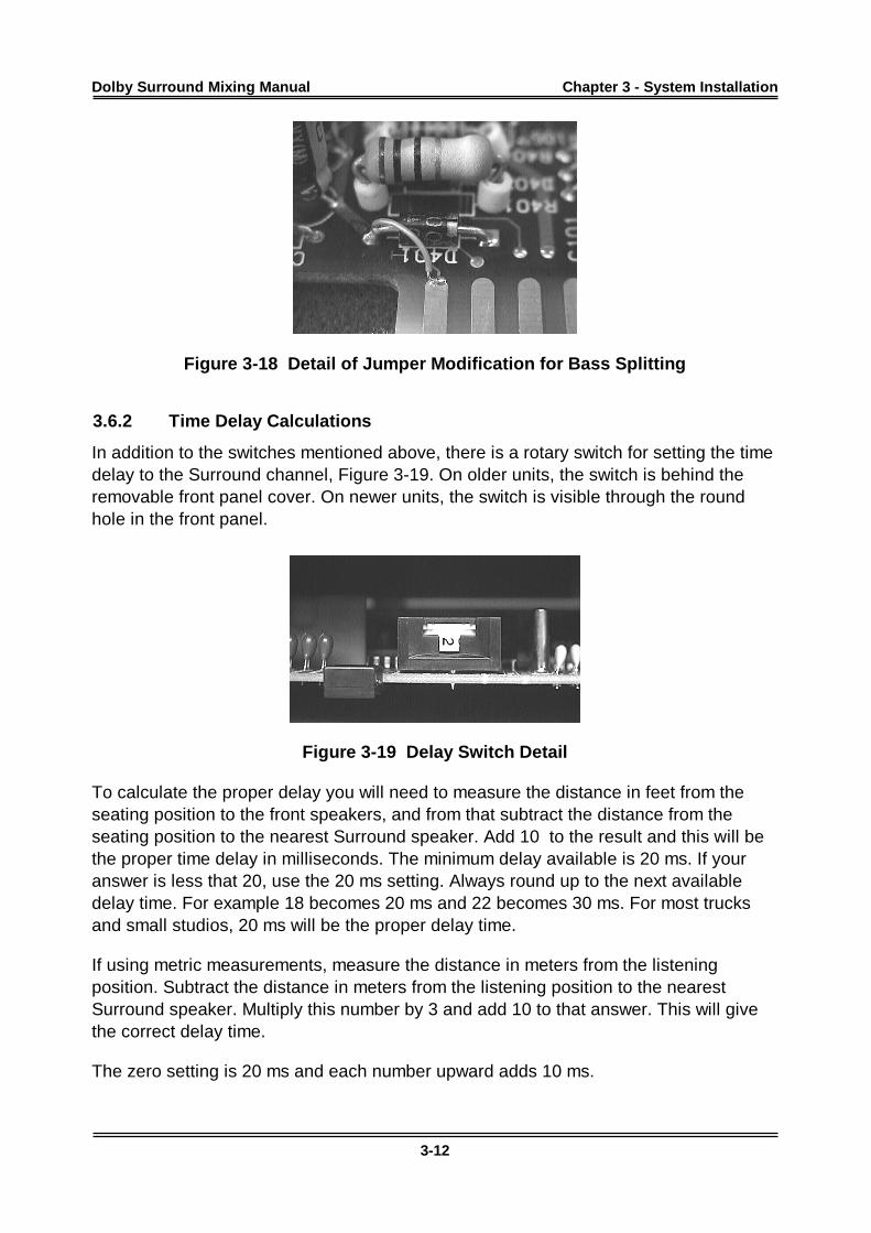
3.6.1 Bass Splitting Modification
In most studio applications, all three front speakers will be identical. In someapplications, however, this is not possible and a smaller version of the Left and Rightspeakers will have to be used for Center. It is important that the midrange and tweetersin the three speakers be identical if possible. In this case, the center woofer will besmaller. Because most bass information is normally found in both the Left and Rightchannels, panned center, the decoder will place these low frequencies in the Centerspeaker. The decoder contains a special feature that can be implemented to take theCenter channel low frequency information below 100 Hz and redistribute it to the leftand right outputs where the larger woofers exist. To enable this feature, a jumper wireneeds to be installed, soldered, between pin T of the Left card (CAT 150E) and theunbanded end of the diode (D401) adjacent to pin T, Figure 3-18. It is important not toget solder on the gold edge card pin except at the very end away from the edge of thecard.
Dolby Surround Mixing Manual Chapter 3 - System Installation
3-12
Figure 3-18 Detail of Jumper Modification for Bass Splitting
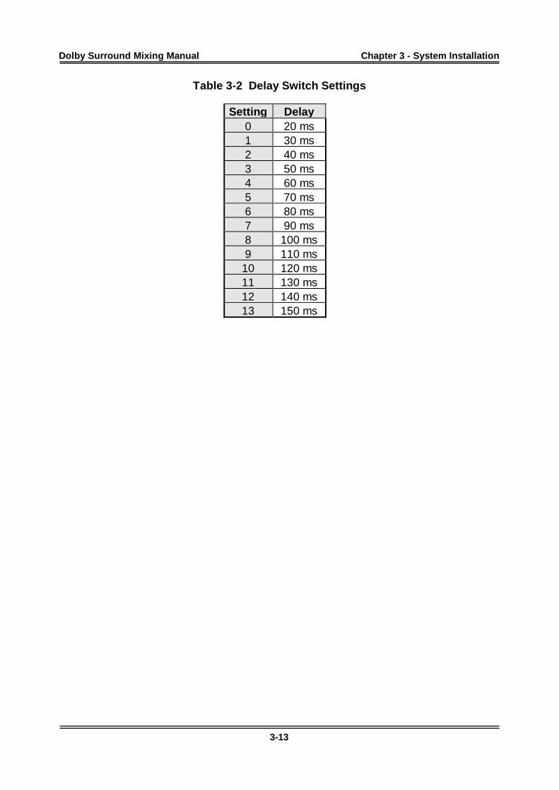
3.6.2 Time Delay Calculations
In addition to the switches mentioned above, there is a rotary switch for setting the timedelay to the Surround channel, Figure 3-19. On older units, the switch is behind theremovable front panel cover. On newer units, the switch is visible through the roundhole in the front panel.
Figure 3-19 Delay Switch Detail
To calculate the proper delay you will need to measure the distance in feet from theseating position to the front speakers, and from that subtract the distance from theseating position to the nearest Surround speaker. Add 10 to the result and this will bethe proper time delay in milliseconds. The minimum delay available is 20 ms. If youranswer is less that 20, use the 20 ms setting. Always round up to the next availabledelay time. For example 18 becomes 20 ms and 22 becomes 30 ms. For most trucksand small studios, 20 ms will be the proper delay time.
If using metric measurements, measure the distance in meters from the listeningposition. Subtract the distance in meters from the listening position to the nearestSurround speaker. Multiply this number by 3 and add 10 to that answer. This will givethe correct delay time.
The zero setting is 20 ms and each number upward adds 10 ms.
Dolby Surround Mixing Manual Chapter 3 - System Installation
3-13
Table 3-2 Delay Switch Settings
Settin g Delay0 20 ms1 30 ms2 40 ms3 50 ms4 60 ms5 70 ms6 80 ms7 90 ms8 100 ms9 110 ms
10 120 ms11 130 ms12 140 ms13 150 ms
Dolby Surround Mixing Manual
4-1
Chapter 4System Set-Up
4.1 Encoder Alignment
In order for proper surround mixing to take place, correct electronic alignment is a must.The following steps should be performed on initial installation of the equipment andshould be checked on a time-to-time basis to verify system integrity.
1. If not already done, connect unit to audio path. See Section 3.2 for furtherinformation. If the effects processor loop is to be used, switch it out for the followingalignments. You will be instructed when to switch it back in. (To disable the EPL,you need to move the slide switch located front center of the right-hand board asshown in Figure 3-17. Access to this switch requires removal of the front cover).
2. Apply a 1 kHz tone at console reference level (+4 dBr, 0 VU, etc.) to the Leftchannel input.
3. Adjust the Left channel trim control until both green LED's on the SEU4 areilluminated. The resolution from left green LED to right green LED is approximately1/4 dB. In some cases it may be difficult to get both green LED's to remain lit.Should you find this to be the case, adjusting so that you are at the crossover pointfrom one green LED to the other will be acceptable.
4. Adjust the Lt output trim pot to reflect console reference on the metering employed,console or recorder. If you are returning the signal through the console masterfader, be sure the fader is set for unity gain. Once the master fader is set, it shouldnot be changed for the remainder of the setup procedure.
5. Apply the 1 kHz reference tone to the Right channel input.
6. Adjust the Right channel input trim and Rt output trim as in steps 3 and 4 above.
7. Apply the 1 kHz reference tone to the Center channel input.
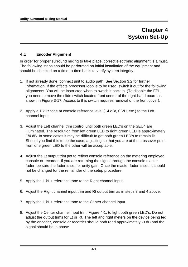
8. Adjust the Center channel input trim, Figure 4-1, to light both green LED's. Do notadjust the output trims for Lt or Rt. The left and right meters on the device being fedby the encoder, console or recorder should both read approximately -3 dB and thesignal should be in phase.
Dolby Surround Mixing Manual Chapter 4 - System Set-Up
4-2
Figure 4-1 Adjusting the Center Input Trim Control
9. Apply the 1 kHz reference tone to the Surround channel input.
10. Adjust the Surround channel input trim to light both green LED's. Again, do notadjust the Lt or Rt output trims. The left and right meters on the device being fed bythe encoder, console or recorder, should both read -3 dB and the signal should be180° out of phase.
11. If the Effects Processor Loop (EPL) is not used, encoder alignment is complete,proceed to decoder alignment.
12. Switch the EPL in.
The EPL contains send and return levels and is used to interface a piece of signalprocessing gear after the encoding to Lt/Rt, but before the final output of the SEU4encoder. These trims are usually set for unity gain at the factory. Should you desire tochange them, you should apply the 1 kHz reference signal to the left and right inputsand adjust left and right EPL sends for the proper level at the signal processing deviceinput. Then adjust the left and right returns to produce for proper level at the SEU4output. To enable the EPL, you need to move the slide switch located front center of theright-hand board (CAT 385). Access to this switch requires removal of the front cover.
4.2 Decoder Alignment
The decoder has two parts to align, the input levels and the output levels.
4.2.1 Input Levels
1. Feed a 1 kHz tone to the left and right inputs of the decoder. (This should be fed tothe encoder, which in turn should be feeding the decoder as well as the rest of thesignal chain.)
Dolby Surround Mixing Manual Chapter 4 - System Set-Up
4-3
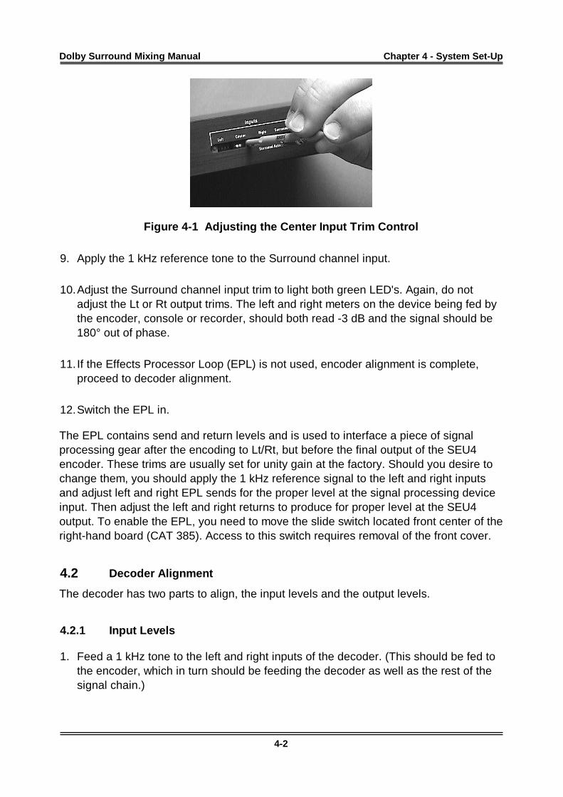
2. Adjust the left and right inputs, Figure 4-2, to light both green LED’s. The inputs arenow aligned.
Figure 4-2 Adjusting the Right Input Trim Control
4.2.2 Output Levels
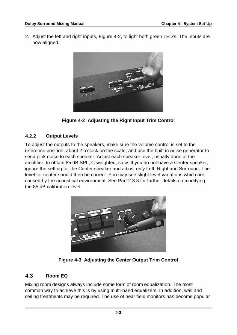
To adjust the outputs to the speakers, make sure the volume control is set to thereference position, about 2 o’clock on the scale, and use the built in noise generator tosend pink noise to each speaker. Adjust each speaker level, usually done at theamplifier, to obtain 85 dB SPL, C-weighted, slow. If you do not have a Center speaker,ignore the setting for the Center speaker and adjust only Left, Right and Surround. Thelevel for center should then be correct. You may see slight level variations which arecaused by the acoustical environment. See Part 2.3.8 for further details on modifyingthe 85 dB calibration level.
Figure 4-3 Adjusting the Center Output Trim Control
4.3 Room EQ
Mixing room designs always include some form of room equalization. The mostcommon way to achieve this is by using multi-band equalizers. In addition, wall andceiling treatments may be required. The use of near field monitors has become popular
Dolby Surround Mixing Manual Chapter 4 - System Set-Up
4-4
recently because the near field monitors are not adversely affected by the roomenvironment.
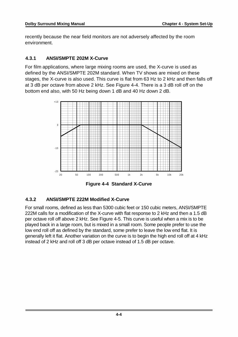
4.3.1 ANSI/SMPTE 202M X-Curve
For film applications, where large mixing rooms are used, the X-curve is used asdefined by the ANSI/SMPTE 202M standard. When TV shows are mixed on thesestages, the X-curve is also used. This curve is flat from 63 Hz to 2 kHz and then falls offat 3 dB per octave from above 2 kHz. See Figure 4-4. There is a 3 dB roll off on thebottom end also, with 50 Hz being down 1 dB and 40 Hz down 2 dB.
20 50 100 200 500 1k 2k 5k 10k 20k
-10
-20
0
+1 0
Figure 4-4 Standard X-Curve
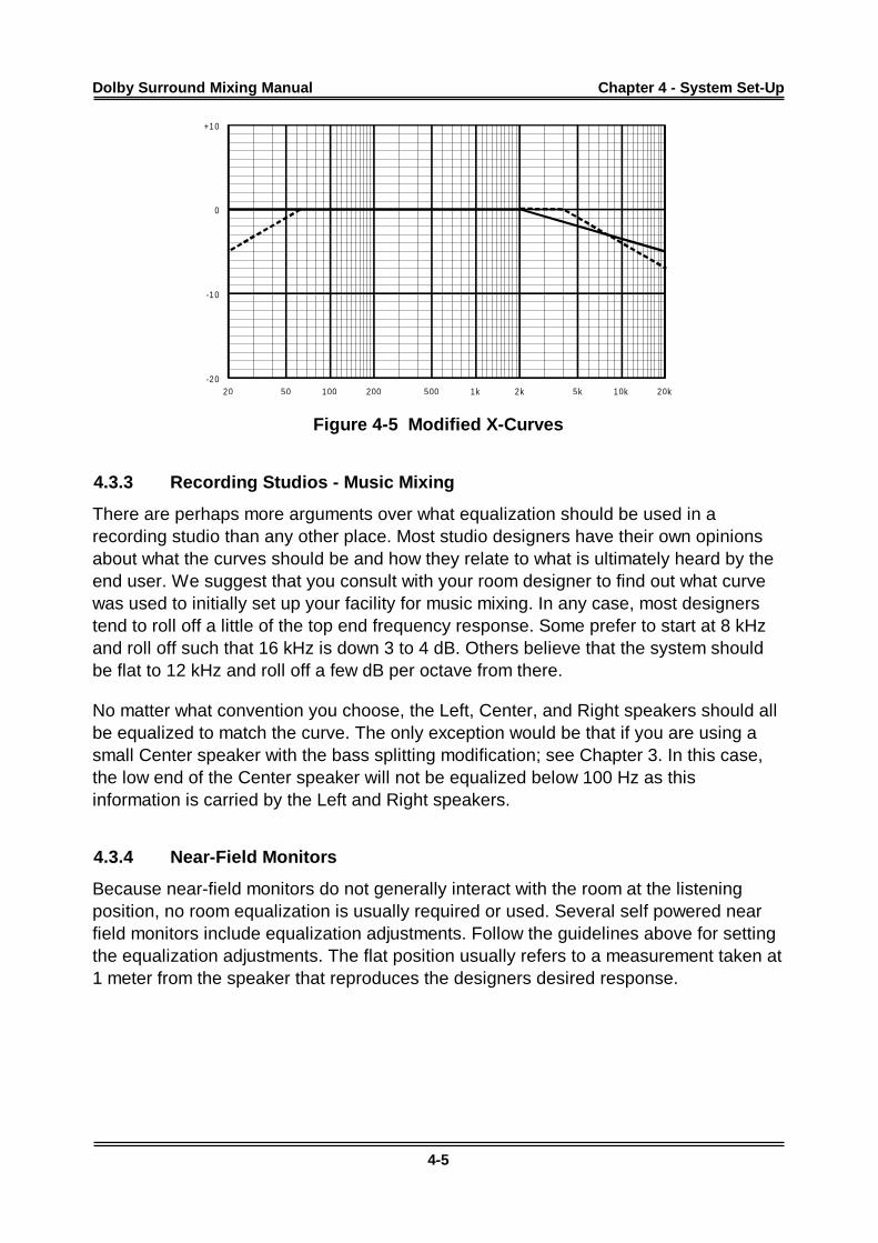
4.3.2 ANSI/SMPTE 222M Modified X-Curve
For small rooms, defined as less than 5300 cubic feet or 150 cubic meters, ANSI/SMPTE222M calls for a modification of the X-curve with flat response to 2 kHz and then a 1.5 dBper octave roll off above 2 kHz. See Figure 4-5. This curve is useful when a mix is to beplayed back in a large room, but is mixed in a small room. Some people prefer to use thelow end roll off as defined by the standard, some prefer to leave the low end flat. It isgenerally left it flat. Another variation on the curve is to begin the high end roll off at 4 kHzinstead of 2 kHz and roll off 3 dB per octave instead of 1.5 dB per octave.
Dolby Surround Mixing Manual Chapter 4 - System Set-Up
4-5
20 50 100 200 500 1k 2k 5k 10k 20k
-10
-20
0
+10
Figure 4-5 Modified X-Curves
4.3.3 Recording Studios - Music Mixing
There are perhaps more arguments over what equalization should be used in arecording studio than any other place. Most studio designers have their own opinionsabout what the curves should be and how they relate to what is ultimately heard by theend user. We suggest that you consult with your room designer to find out what curvewas used to initially set up your facility for music mixing. In any case, most designerstend to roll off a little of the top end frequency response. Some prefer to start at 8 kHzand roll off such that 16 kHz is down 3 to 4 dB. Others believe that the system shouldbe flat to 12 kHz and roll off a few dB per octave from there.
No matter what convention you choose, the Left, Center, and Right speakers should allbe equalized to match the curve. The only exception would be that if you are using asmall Center speaker with the bass splitting modification; see Chapter 3. In this case,the low end of the Center speaker will not be equalized below 100 Hz as thisinformation is carried by the Left and Right speakers.
4.3.4 Near-Field Monitors
Because near-field monitors do not generally interact with the room at the listeningposition, no room equalization is usually required or used. Several self powered nearfield monitors include equalization adjustments. Follow the guidelines above for settingthe equalization adjustments. The flat position usually refers to a measurement taken at1 meter from the speaker that reproduces the designers desired response.
Dolby Surround Mixing Manual
5-1
Chapter 5Mixing Techniques
5.1 Announcers and Dialog
Traditionally, dialog has been placed only in the Center speaker to keep the on-screensounds tied to the picture. When a Center speaker is used, all center panned dialoguewill appear to come from the screen regardless of where the listener is seated. If thedialogue were to come from the Left or Right speakers, the stereo image would differdepending on the listener’s choice of seat. This is highly undesirable. This does notmean that voices cannot appear in the other channels, but generally only effects orincidental voices should be in any channel other than center.
5.2 Interior Effects
Interior effects are sounds that come from all four channels and appear to surround thelistener. Examples of interior effects are wind noise, crowds, and other general ambientsounds that are included within the mix to give a sense of realism. Effects andambiance sounds will normally appear in the Left, Right, and Surround channels.Common practice is to use Stereo ambiance that is panned left and Surround for theLeft channel of the source and Right and Surround for the Right channel of the source.The result is a sound that surrounds the listener, yet still has a front stereo image. Theamount of Surround channel signal added will determine how far back the listener is inrelation to the front sounds. More surround level produces an image that sounds furtherback in the room.
Sometimes a mono element is all that is available, yet a surround effect is desired. Inthis case, the signal can be put in both the Center and Surround channels. This iscommonly known as a 2-4 punch. By applying it equally to both Center and Surround,the sound will appear to come from all four channels. Stereo reverb can also be usedwith a mono sound element to give a slightly wider image. Simply apply the reverbeffect to the Left and Right channels while applying the original dry signal to the Centerand Surround channels.
Another technique that frequently works is to take the signal and assign it to the Leftchannel and add an 8 millisecond or so delay of the same signal to the Right channel.This may or may not produce acceptable results depending on the program material.
5.3 Positioning of the Stereo Image
Because of the Center speaker, the stereo imaging in a Dolby Surround system isslightly different than in a two speaker stereo system. Most music engineers find thisdistracting at first, but adjust quickly. Those used to mixing motion picture sound feel
Dolby Surround Mixing Manual Chapter 5 - Mixing Techniques
5-2
right at home as do those music engineers who have their own home theater systems.The most noticeable difference in the stereo image is that the perceived image will tendto be narrower when a Center speaker is used. This is because most music mixescontain significant amounts of Center channel information that we are used to hearingas a phantom image produced by the Left and Right speakers. Since all of thisinformation is now being directed to a single point source, the Center speaker, weperceive it as all center. To correct for this in the mix, simply make the image slightlywider than is normally done for a two channel stereo mix.
A mistake that should be avoided is to eliminate the Center speaker in the control roomand use the phantom monitoring mode. While this may produce a more familiar soundin the control room, it does not address the listeners at home who have a completehome theater system. The mix produced with a Center speaker will be somewhatdifferent and this the correct listening method.
5.4 Panning Sounds
There are several different ways to pan sounds in a mix. The best way is to have film-style multichannel panners that pan from left to center to right and from front to back.This type of panning system will allow you to position a sound anywhere in the soundfield with little effort.
If film style panners are not available, panning from left to right on one stereo buss andcenter to surround on a second stereo buss can also be an effective way to placesounds, although this technique is not as easy to use, especially for moving effects.
On small, function limited consoles, the front channel panning can be accomplishedusing the stereo buss and the Surround channel can be fed by an auxiliary buss. Thisis extremely limiting in use, but will work if necessary. For complicated panning moves,bringing up the signal on more than one fader, with each fader feeding a differentoutput, will allow you to use the faders as panners.
For example, assigning one fader to the left/right pan, with the pan pot set halfwaybetween left and center, and another fader assigned to the surround buss will allow youto pan from left center to surround by bringing up the fader feeding the Surroundchannel as the fader feeding the left/right busses is brought down. If the console isautomated, these moves can be perfected one at a time and then repeated by theautomation system. This method will also work on larger consoles where automatedpans are required.
By taking the signal and assigning it to four faders, with each fader assigned to adifferent input of the encoder, a circle pan can also be created.
Dolby Surround Mixing Manual Chapter 5 - Mixing Techniques
5-3
5.5 Stacking Encoded Tracks
A common practice in the film industry is to premix elements for the final mix. This couldbe done for the opening sequence for a series of shows or a sound effect panningthrough the room.
The individual elements may be mixed as Dolby Surround encoded 2-channel elements(Lt/Rt) and all of those elements may be mixed together in the final mix. When doingthis, each element should be assigned to the left and right inputs of the encoder.
5.6 Magic Surround
In certain cases, stereo microphone placement techniques and stereo electronicinstruments will cause a phenomenon known as magic surround. In these cases, someof the signal will be decoded by the decoder and placed in the Surround channel. Thecause of this is out of phase or inverted information in the stereo pair. XY stereomicrophone techniques will almost always produce this effect. While this may soundpleasing by itself and you may feel that no encoding is necessary, this process isunpredictable and should not be relied on. A simple addition of another element in themix such as a voiceover could easily change the phase characteristics of the mix andthe decoder would no longer decode the same way. The best thing to do is put at leasta little information from this signal source through the surround input of the encoder.This will ensure that the decoder will decode the real surround signals and not somerandom out of phase information.
In some cases. too much surround information may be present. This is especially truewith electronic keyboards which use electronic processing to achieve a stereo signalfrom a mono source. If you have too much information in the Surround channel withyour favorite sound, simply pan the left a little towards center and the right an equalamount towards center. This will cancel out some of the out of phase information andmake the decoder work normally again. The amount of panning required will vary withthe sound, but it usually does not take much to produce a good result.
5.7 Decoder Mistracking and Steering Artifacts
When mixing, you will quickly realize that the decoder can only steer in one direction ata time. This requires careful planning of the sound field. Before you begin to think thatthis sounds impossible, movie mixers have been successfully doing just that for morethan 20 years. It can be done quite easily.
Troubles usually occur when two very different and unrelated sounds are sent to twodifferent channels at once. For example, crickets in the Surround channel and chickensin the front. The result is that the sounds bleed into the other channels and produce adynamic image shift as they do. This effect is very distracting and undesirable.
Dolby Surround Mixing Manual Chapter 5 - Mixing Techniques
5-4
Another common occurrence is when a music track contains a lead instrument that isprominent in the mix in the Left or Right channel while an announcer comes and goesfrom the Center channel. In this case, the instrument will appear to move from itsintended speaker towards the center when the announcer speaks and then return to thecorrect speaker when the announcer stops talking. The solution here is to either panthe music element towards center or reduce its level until the problem goes away.
Often, when producing sound effects for motion pictures, the sound effects designer willremove all ambient sounds briefly to allow for another sound to be more prominentlyheard. For example, there may be night time sounds and a little traffic in thebackground. The next big sound might be a door slam. While the door is slamming, thetraffic and night sounds will either be very low in level or will disappear entirely. Whenthe door slam sound is gone, the other sounds are already back in the mix. They willnever be missed by the audience as the door slam would have covered over themanyway.
5.8 Surround Pumping
Pumping of the Surround channel is frequently caused by bad transmission paths andis rarely heard in the mixing environment. A common problem is that a limiter is activein one channel of the transmission path but not the other, or a stereo limiter is not setup the same for both channels. The solution is to either remove the limiters or set themup identically and verify that they are linked together. This problem can be heard duringthe mix if a stereo limiter is being used excessively or if part of the element is limited,but not all of it. It is impossible to cover every possibility here, but look for inconsistencybetween the two stereo channels as the likely cause of the problem. The problem isusually noticed by the viewer as Surround channel ambience pumping in response tothe dialog. This can be particularly noticeable during live sporting broadcasts whenthere is crowd noise in the Surround channel.
5.9 Proper Surround Level and Content
When is there enough surround content? This question is usually left up to the taste ofthe producer and engineer mixing the project. As a guideline, the image should directyour attention to the front of the sound field and the listener should notice somethingmissing when the Surround channel is removed from the mix, but should not have theirattention drawn directly to the Surround channel when it is returned to the mix.Surround channel effects should complement on-screen action and should not bedistracting. There is no right or wrong mix within reason.
5.10 Limiters, Delays, Reverb Units, Other Effects Processors
As with any mixing situation, signal processing devices are common in Dolby Surroundmixes. Limiters and compressors are easily used with little side effects as long as they
Dolby Surround Mixing Manual Chapter 5 - Mixing Techniques
5-5
are used before the encoder. Digital delays and sound field generators, reverbs, etc.,may also be used. However, the tricks used to generate the sound fields from theseeffects may not work as expected when Dolby Surround decoding is used. Since youare monitoring through a decoder, you can instantly hear what the sound field willactually sound like. If you find that your favorite reverb program has excessive surroundcontent without sending anything to the Surround channel, try taking the stereo outputof the device and panning it a little towards the center instead of hard left and right.Experimentation will be required to get the exact sound you desire. This effect iscaused by the phase shifting of the effects unit competing with the phase encodingfound in Dolby Surround; stereo keyboards also have this problem.
5.11 Mono to Stereo Synthesizers
Mono to stereo synthesizers can create all sorts of havoc in a Dolby Surround mix.First, the Dolby Surround program is a stereo signal so there is no need for asynthesizer in the transmission path. Second, if you have ever listened to a mono showrun through an aggressively adjusted stereo synthesizer, and then through a surrounddecoder, you have experienced the dialog coming from all the speakers all the time. Alllocalization of the voices to the screen is lost. For this reason, with complete mixes, thisis not a desired tool in the transmission path. This is not to say that a stereosynthesizer can't be used to an advantage for individual mono sources within a DolbySurround mix during production and before encoding. When used properly, they can beeffective on certain elements. They should not, however, be used excessively whendialog or vocals are part of the mono element.
5.12 Dolby Surround Compatible Processors
There are several Dolby Surround compatible processors available now. As is the casewith reverb processors, these units can offer mixed results. If the unit is supposed tosubstitute for a real Dolby Surround encoder, ask yourself “why not use the real thing?”Units that are designed for use with two speakers, 3D audio processors, can be usedwith pleasing results. The secret is to listen to the mix through a Dolby Surrounddecoder so you know what it will actually sound like to the end user. Encoders that aredesigned to be used with their own decoders are another issue. The real issue is howmany consumers are going to be able to hear the mix with the proper decoder. DolbySurround is the de facto standard matrix surround system worldwide. If a listener has asurround decoder, it most likely is a Dolby Surround decoder.
5.13 Mono, Stereo and Dolby Surround Compatibility
Mixing techniques used in Dolby Surround productions are similar to those used innormal stereo productions. Just as you should check mono compatibility of a stereomix, you should also check mono and stereo compatibility of a Dolby Surround mix.
Dolby Surround Mixing Manual Chapter 5 - Mixing Techniques
5-6
In most cases, stereo compatibility is not an issue. The surround element of the mix willappear to be outside of the speakers as an out of phase signal would. Notice that theentire mix should not sound out of phase, and there should still be a hard center image.
Mono compatibility is a little trickier. Anything that is in the Surround channel willdisappear in mono. This can be considered an asset in some cases and a detriment inothers.
In situations like live sporting events, the lack of some crowd information in the monomix will help those at home listening in mono on a 3-inch television speaker to hear theannouncers a little easier. In other applications, the mix may have a critical element in itthat is predominately in the Surround channel. For this reason, surround elementsshould also be present in a front channel, interior panned, so they will be heard inmono, as is commonly practiced in the film industry.
5.14 Monitoring
For applications where tracks are being generated for use with other elements like amusic mix for film or video, it is often desirable to monitor through a Dolby Surrounddecoder. These tracks are seldom mixed and encoded before delivery, but arecommonly sent as elements on separate tracks (L, C, R, and S). It is important that youknow that the elements are acceptable when run through the Dolby Surround encodingsystem during the final mix or undesirable results could be present. The two mostcommon problems are soundtracks that are very mono in nature or that contain phaseinformation that make them sound surround heavy. The measures required to correctthese problems at the final mix session will compromise the mix of the elements, and sothese problems should be corrected before the four channel elements are recorded.
5.15 Common Pitfalls
Although you may like a surround effect that spins your head around, and it may be justwhat your production needs, repeating that move dozens of times will usually be tiringto the listener. The key to good surround mixes is being subtle with the effect. Don’tdraw attention to the techniques you are using. The listener should never stop payingattention to what is happening up front while they try to figure out what they just heardcoming from the back. Loud, obnoxious or out of place effects are distractions, notadditions. Keep it fun, but keep it tasteful too.
Another pitfall is too much information in the Surround channel. It is better to be a littleshy on surround information. Mixes that are surround heavy will distract the viewer fromthe on screen action. If you find yourself thinking about what you just heard in theSurround channel instead of paying attention to the action on the screen, you have toomuch surround information. Too much surround information may also make dialogintelligibility suffer to the point where it can be difficult to understand the actors lines.
Dolby Surround Mixing Manual
6-1
Chapter 6Live Broadcast Applications
6.1 Transmission Path Considerations
With fiber optic and satellite transmission lines being standard fare at sports arenasand stadiums, this part of the signal chain is usually repeatable and predictable.Frequency response and headroom often remain very consistent from event to event.Most of the early problems encountered in Dolby Surround broadcasts were related toadditional signal processing introduced by the station. The two most common offenderswere phase chasers and stereo synthesizers.
6.2 Phase Chasers
Because Dolby Surround uses phase encoding of the Surround channel, it is entirelypossible to have situations where significant out of phase information in the programcannot and should not be corrected, even by well-meaning devices. There are twobasic functions performed by phase chasing devices. One is to correct the small phaseerrors between two audio channels, such as from azimuth misalignment or drift inanalog video tape recorders and cart machines; the other is to correct polarityinversions in one channel relative to the other. When either function occurs in responseto Dolby Surround signals, the results can be both unnecessary and unfortunate.
With live feeds or audio sourced from a digital recorder becoming the norm, phasecorrection is essentially unnecessary, as there is no azimuth error introduced. Relativepolarity can be easily checked before air time, and this is especially easy whenmonitoring at the station through an SDU4. If the announcer or dialog comes out theSurround channel, or becomes virtually inaudible in mono, the polarity is inverted! Asmany people still listen in mono, loss of the announcer either during the game or duringa commercial is bound to raise complaints from one party or another.
6.3 Station Limiters
No matter how good your mix, stations will always try to extract that last quarter dB fromthe transmitter. The usual way of doing this is with a program limiter. In general, use ofthese should be avoided. Since we live in a real world, stations need to set these up forminimal effect. Mixers need to mix such that these devices are not required to limit theprogram material in order to keep the mix in the useful range of the transmitter.
Dolby Surround Mixing Manual Chapter 6 - Live Broad cast A pplications
6-2
6.4 Station Processing
Along with station program limiters, other signal processors may be used, including theDolby Model 740 Spectral Processor. While there is little that a mixer can do while onlocation to defeat the use of these units, if they have been properly set up, without toomuch radical signal processing, they should not pose a problem.
6.5 Headroom
The amount of available headroom will depend on what the final distribution medium is.In broadcast transmission applications 6 dB of headroom above reference level is theusual limit. For transmission paths between venues and satellite uplinks, 10 dB may beavailable. VHS tape hi-fi tracks have about 12 dB of headroom. CDs, laser discs anddigital video recorders have 20 dB of headroom. It is important that you know whatheadroom is available and stay within the boundaries. Failure to do so will createunwanted side effects. The headroom of the encoder and decoder are sufficient for anyof the requirements above.
6.6 Stereo Synthesizers In Transmission Paths
Although stereo synthesizers, used to make mono programs stereo, are less commonnow than they were when stereo TV first became a reality, they are st ill in use. Theymust not be used in the transmission path of a Dolby Surround encoded soundtrackafter the encoding process. Use of these devices will destroy all surround encoding.Also, although the effect may sound all right to some people in stereo for a monoprogram, the result of any stereo synthesized program when decoded through a DolbySurround decoder is nothing short of obnoxious.
Dolby Surround Mixing Manual
7-1
Chapter 7Video Games and Multimedia
7.1 Introduction
Dolby Surround has become a popular tool for video game and multimedia developers.There are several ways to include Dolby Surround within a video game, and each isdependent on the platform used by the game.
It is often desired to be able to control the spatial position of a sound in response to thegame player’s input. There are several techniques that can be used to achieve this inthe game itself. The degree of complexity and resulting quality varies, and so thetechnique should be chosen based on what is appropriate for the intended effect.
7.2 Normal Dolby Surround Encoding
The easiest way is to simply encode all of the audio files for the game in DolbySurround. This will give you a pleasing, but non-interactive soundtrack. To accomplishthis, mix the project as you would any other type of project and save the sounds asstereo files with the game.
7.3 Polarity Inversion
The second method is to emulate Dolby Surround. This is common in cartridge games.This method allows you to place sounds at each of the four cardinal points, Left,Center, Right and Surround. This is an approximation of Dolby Surround and is limitedin its capability. For simple cartridge games where sound file space is at a premium,this technique will produce an adequate Dolby Surround effect.
Effects such as door creaks or gun shots need to follow the action on the screen. Thesesounds occur less frequently, and are usually mono elements that are cached andlooped. Sound placement can be handled within the game itself, using only basiccontrols. The front cardinal points, Left, Center, and Right, can be encoded by panninglike any conventional stereo signal. Simple channel switching during game play allowsthe sound to be output from the Left, Right or Center (both channels). If the gameprovides a variable balance control function, the sound may be smoothly pannedacross the front or positioned between channels.
The simple frontal positioning may be adequate for many sounds that need run-timecontrol. For more realism, placing sounds in the Surround channel may be desired aswell.
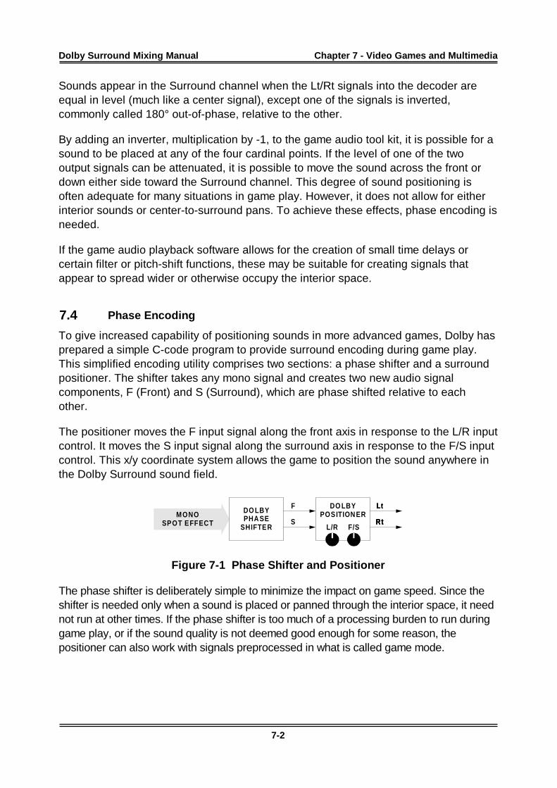
Dolby Surround Mixing Manual Chapter 7 - Video G ames and Multimedia
7-2
Sounds appear in the Surround channel when the Lt/Rt signals into the decoder areequal in level (much like a center signal), except one of the signals is inverted,commonly called 180° out-of-phase, relative to the other.
By adding an inverter, multiplication by -1, to the game audio tool kit, it is possible for asound to be placed at any of the four cardinal points. If the level of one of the twooutput signals can be attenuated, it is possible to move the sound across the front ordown either side toward the Surround channel. This degree of sound positioning isoften adequate for many situations in game play. However, it does not allow for eitherinterior sounds or center-to-surround pans. To achieve these effects, phase encoding isneeded.
If the game audio playback software allows for the creation of small time delays orcertain filter or pitch-shift functions, these may be suitable for creating signals thatappear to spread wider or otherwise occupy the interior space.
7.4 Phase Encoding
To give increased capability of positioning sounds in more advanced games, Dolby hasprepared a simple C-code program to provide surround encoding during game play.This simplified encoding utility comprises two sections: a phase shifter and a surroundpositioner. The shifter takes any mono signal and creates two new audio signalcomponents, F (Front) and S (Surround), which are phase shifted relative to eachother.
The positioner moves the F input signal along the front axis in response to the L/R inputcontrol. It moves the S input signal along the surround axis in response to the F/S inputcontrol. This x/y coordinate system allows the game to position the sound anywhere inthe Dolby Surround sound field.
MONOSPOT EFFECT
Lt
Rt
Lt
Rt
Lt
Rt
DO LBYPHA SE
SHIFTER
F
S
DO LBYPOSITION ER
L/R F/S
Figure 7-1 Phase Shifter and Positioner
The phase shifter is deliberately simple to minimize the impact on game speed. Since theshifter is needed only when a sound is placed or panned through the interior space, it neednot run at other times. If the phase shifter is too much of a processing burden to run duringgame play, or if the sound quality is not deemed good enough for some reason, thepositioner can also work with signals preprocessed in what is called game mode.
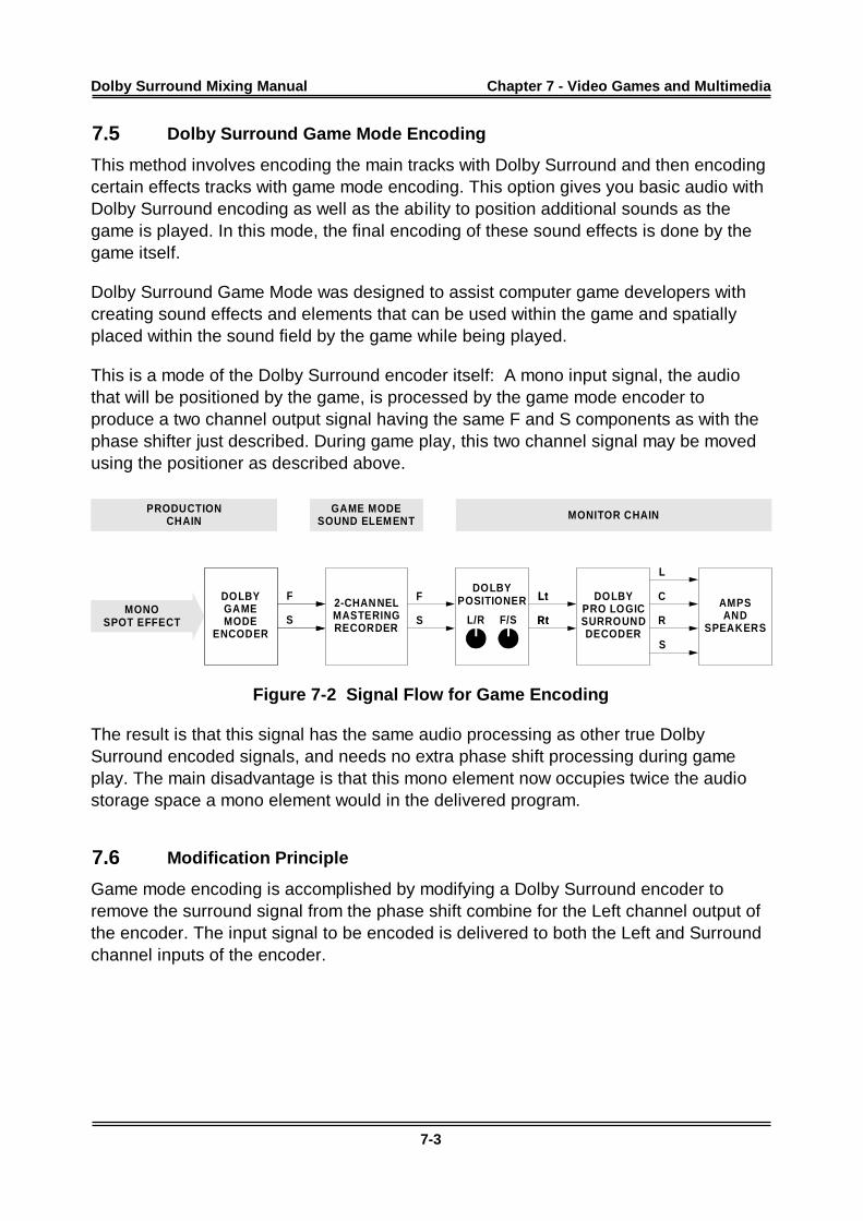
Dolby Surround Mixing Manual Chapter 7 - Video G ames and Multimedia
7-3
7.5 Dolby Surround Game Mode Encoding
This method involves encoding the main tracks with Dolby Surround and then encodingcertain effects tracks with game mode encoding. This option gives you basic audio withDolby Surround encoding as well as the ability to position additional sounds as thegame is played. In this mode, the final encoding of these sound effects is done by thegame itself.
Dolby Surround Game Mode was designed to assist computer game developers withcreating sound effects and elements that can be used within the game and spatiallyplaced within the sound field by the game while being played.
This is a mode of the Dolby Surround encoder itself: A mono input signal, the audiothat will be positioned by the game, is processed by the game mode encoder toproduce a two channel output signal having the same F and S components as with thephase shifter just described. During game play, this two channel signal may be movedusing the positioner as described above.
DOLBYGAMEMODE
ENCODER
2-CHAN NELMASTERINGRECORDER
F
S
F
S
GAME MODESOUND ELEMENT
DOLBYPRO LOGICSURROUNDDECODER
L
C
R
S
MONITOR CHAIN
Lt
Rt
Lt
Rt
AMPSAND
SPEAKERS
PRODUCTIONCHAIN
MONOSPOT EFFECT
DOLBYPOSITIONER
L/R F/S
Figure 7-2 Signal Flow for Game Encoding
The result is that this signal has the same audio processing as other true DolbySurround encoded signals, and needs no extra phase shift processing during gameplay. The main disadvantage is that this mono element now occupies twice the audiostorage space a mono element would in the delivered program.
7.6 Modification Principle
Game mode encoding is accomplished by modifying a Dolby Surround encoder toremove the surround signal from the phase shift combine for the Left channel output ofthe encoder. The input signal to be encoded is delivered to both the Left and Surroundchannel inputs of the encoder.
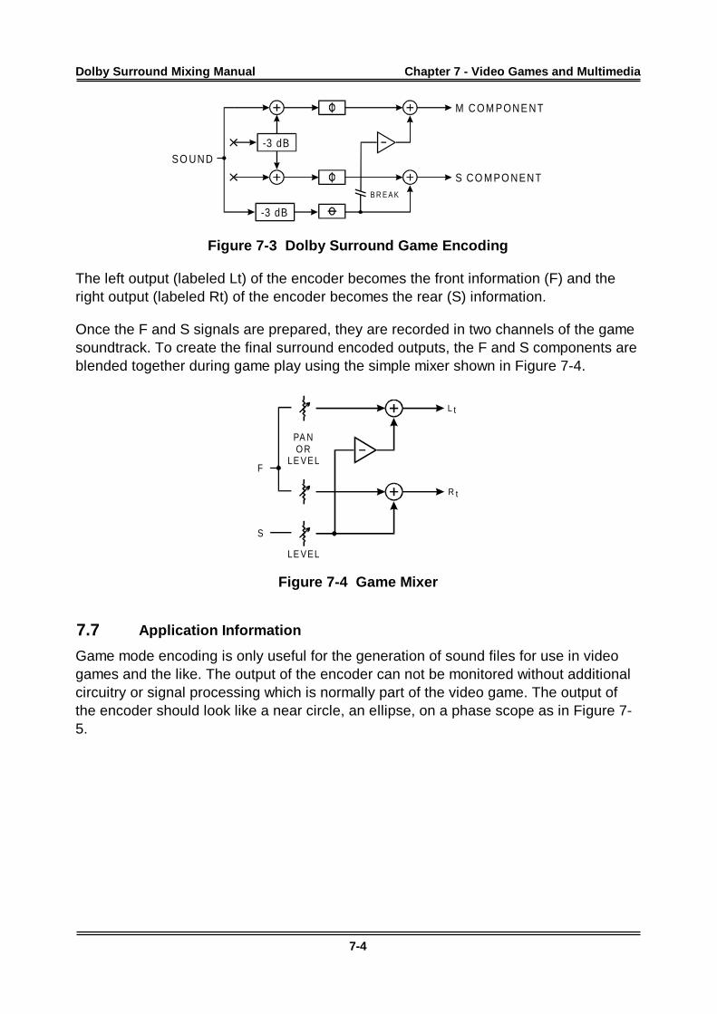
Dolby Surround Mixing Manual Chapter 7 - Video G ames and Multimedia
7-4
-3 dB
-3 dB
B R E A K
M COM PONE NT
S CO MPO NENT
SO UND
Figure 7-3 Dolby Surround Game Encoding
The left output (labeled Lt) of the encoder becomes the front information (F) and theright output (labeled Rt) of the encoder becomes the rear (S) information.
Once the F and S signals are prepared, they are recorded in two channels of the gamesoundtrack. To create the final surround encoded outputs, the F and S components areblended together during game play using the simple mixer shown in Figure 7-4.
L
R
t
t
PA NO R
LE VEL
LE VEL
F
S
Figure 7-4 Game Mixer
7.7 Application Information
Game mode encoding is only useful for the generation of sound files for use in videogames and the like. The output of the encoder can not be monitored without additionalcircuitry or signal processing which is normally part of the video game. The output ofthe encoder should look like a near circle, an ellipse, on a phase scope as in Figure 7-5.
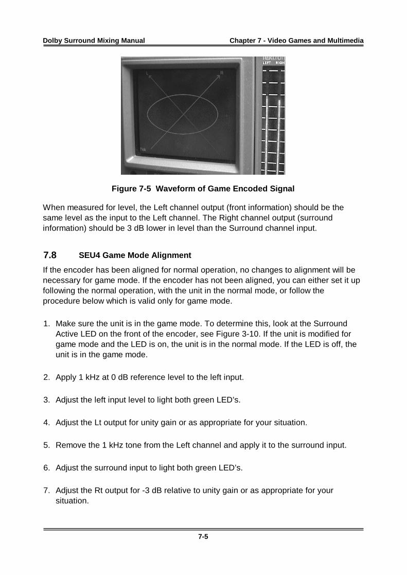
Dolby Surround Mixing Manual Chapter 7 - Video G ames and Multimedia
7-5
Figure 7-5 Waveform of Game Encoded Signal
When measured for level, the Left channel output (front information) should be thesame level as the input to the Left channel. The Right channel output (surroundinformation) should be 3 dB lower in level than the Surround channel input.
7.8 SEU4 Game Mode Alignment
If the encoder has been aligned for normal operation, no changes to alignment will benecessary for game mode. If the encoder has not been aligned, you can either set it upfollowing the normal operation, with the unit in the normal mode, or follow theprocedure below which is valid only for game mode.
1. Make sure the unit is in the game mode. To determine this, look at the SurroundActive LED on the front of the encoder, see Figure 3-10. If the unit is modified forgame mode and the LED is on, the unit is in the normal mode. If the LED is off, theunit is in the game mode.
2. Apply 1 kHz at 0 dB reference level to the left input.
3. Adjust the left input level to light both green LED’s.
4. Adjust the Lt output for unity gain or as appropriate for your situation.
5. Remove the 1 kHz tone from the Left channel and apply it to the surround input.
6. Adjust the surround input to light both green LED’s.
7. Adjust the Rt output for -3 dB relative to unity gain or as appropriate for yoursituation.
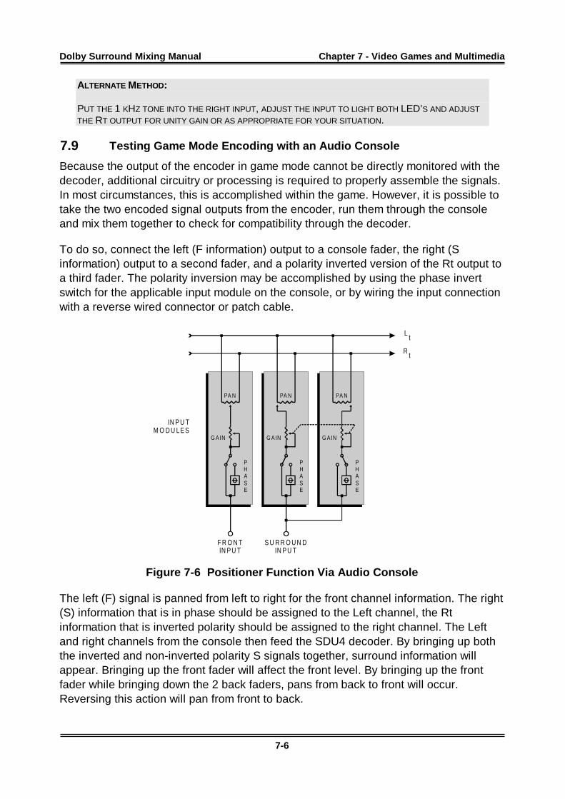
Dolby Surround Mixing Manual Chapter 7 - Video G ames and Multimedia
7-6
ALTERNATE METHOD:
PUT THE 1 KHZ TONE INTO THE RIGHT INPUT, ADJUST THE INPUT TO LIGHT BOTH LED’S AND ADJUST
THE RT OUTPUT FOR UNITY GAIN OR AS APPROPRIATE FOR YOUR SITUATION.
7.9 Testing Game Mode Encoding with an Audio Console
Because the output of the encoder in game mode cannot be directly monitored with thedecoder, additional circuitry or processing is required to properly assemble the signals.In most circumstances, this is accomplished within the game. However, it is possible totake the two encoded signal outputs from the encoder, run them through the consoleand mix them together to check for compatibility through the decoder.
To do so, connect the left (F information) output to a console fader, the right (Sinformation) output to a second fader, and a polarity inverted version of the Rt output toa third fader. The polarity inversion may be accomplished by using the phase invertswitch for the applicable input module on the console, or by wiring the input connectionwith a reverse wired connector or patch cable.
Lt
R t
PA N PA N PA N
G A IN G A IN G A IN
PHASE
PHASE
PHASE
IN P U TM O D U LE S
F R O N TIN P U T
S U R R O U N DIN P U T
Figure 7-6 Positioner Function Via Audio Console
The left (F) signal is panned from left to right for the front channel information. The right(S) information that is in phase should be assigned to the Left channel, the Rtinformation that is inverted polarity should be assigned to the right channel. The Leftand right channels from the console then feed the SDU4 decoder. By bringing up boththe inverted and non-inverted polarity S signals together, surround information willappear. Bringing up the front fader will affect the front level. By bringing up the frontfader while bringing down the 2 back faders, pans from back to front will occur.Reversing this action will pan from front to back.
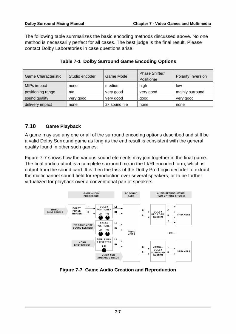
Dolby Surround Mixing Manual Chapter 7 - Video G ames and Multimedia
7-7
The following table summarizes the basic encoding methods discussed above. No onemethod is necessarily perfect for all cases. The best judge is the final result. Pleasecontact Dolby Laboratories in case questions arise.
Table 7-1 Dolby Surround Game Encoding Options
Game Characteristic Studio encoder Game ModePhase Shifter/
PositionerPolarity Inversion
MIPs impact none medium high low
positioning range n/a very good very good mainly surround
sound quality very good very good good very good
delivery impact none 2x sound file none none
7.10 Game Playback
A game may use any one or all of the surround encoding options described and still bea valid Dolby Surround game as long as the end result is consistent with the generalquality found in other such games.
Figure 7-7 shows how the various sound elements may join together in the final game.The final audio output is a complete surround mix in the Lt/Rt encoded form, which isoutput from the sound card. It is then the task of the Dolby Pro Logic decoder to extractthe multichannel sound field for reproduction over several speakers, or to be furthervirtualized for playback over a conventional pair of speakers.
AUDIOMIXER
F/S GAME MODESOUND ELEMENT
MUSIC AN DAMBIANCE TRACK
MONOSPOT EFFECT
GA ME AUDIOPROCESSOR
PC SOUNDCARD
Lt
Rt
Lt
Rt
SIMPLE PAN& INVERTOR
Lt
Rt
Lt
Rt
DOLBYPRO LOGIC
SYSTEM
L
C
R
S
Lt
Rt
Lt
Rt SPEAKERS
AUDIO REPRODUC TION(TW O OPTION S SHOW N)
VIR TUALDOLBY
SURROUNDSYSTEM
L
R
Lt
Rt
Lt
Rt SPEAKERS
-- OR --
DOLBYPOSITIONER
Lt
Rt
Lt
Rt
DOLBYPHASE
SHIFTER
F
S
MONOSPOT EFFECT
L/R F/S
DOLBYPOSITIONER
L/R F/S
L/R
Figure 7-7 Game Audio Creation and Reproduction
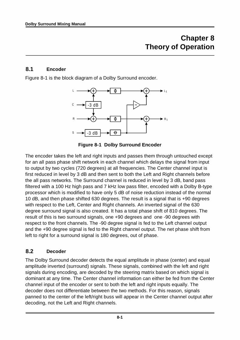
Dolby Surround Mixing Manual
8-1
Chapter 8Theory of Operation
8.1 Encoder
Figure 8-1 is the block diagram of a Dolby Surround encoder.
-3 dB
-3 dB
LL
C
S
RR
t
t
Figure 8-1 Dolby Surround Encoder
The encoder takes the left and right inputs and passes them through untouched exceptfor an all pass phase shift network in each channel which delays the signal from inputto output by two cycles (720 degrees) at all frequencies. The Center channel input isfirst reduced in level by 3 dB and then sent to both the Left and Right channels beforethe all pass networks. The Surround channel is reduced in level by 3 dB, band passfiltered with a 100 Hz high pass and 7 kHz low pass filter, encoded with a Dolby B-typeprocessor which is modified to have only 5 dB of noise reduction instead of the normal10 dB, and then phase shifted 630 degrees. The result is a signal that is +90 degreeswith respect to the Left, Center and Right channels. An inverted signal of the 630degree surround signal is also created. It has a total phase shift of 810 degrees. Theresult of this is two surround signals, one +90 degrees and one -90 degrees withrespect to the front channels. The -90 degree signal is fed to the Left channel outputand the +90 degree signal is fed to the Right channel output. The net phase shift fromleft to right for a surround signal is 180 degrees, out of phase.
8.2 Decoder
The Dolby Surround decoder detects the equal amplitude in phase (center) and equalamplitude inverted (surround) signals. These signals, combined with the left and rightsignals during encoding, are decoded by the steering matrix based on which signal isdominant at any time. The Center channel information can either be fed from the Centerchannel input of the encoder or sent to both the left and right inputs equally. Thedecoder does not differentiate between the two methods. For this reason, signalspanned to the center of the left/right buss will appear in the Center channel output afterdecoding, not the Left and Right channels.
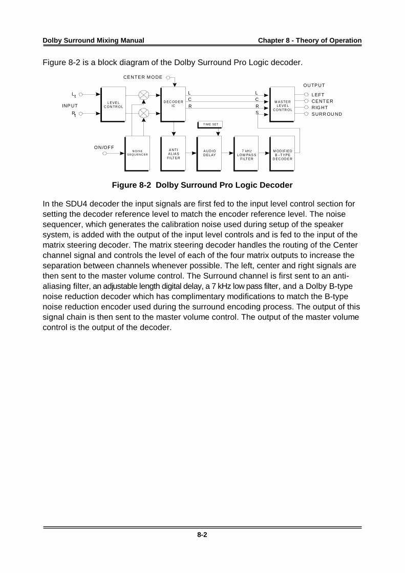
Dolby Surround Mixing Manual Chapter 8 - Theory of Op eration
8-2
Figure 8-2 is a block diagram of the Dolby Surround Pro Logic decoder.
Lt
Rt
LEFTCENT ERRIG HTSURR OU ND
L LC C
R RS
L EVE LC O N TR O L
D EC OD E RIC
N OIS ES EQ U EN C ER
A NT IA LIAS
F ILT ER
A UD IOD EL AY
M AST ERL EVE L
C O N TR O L
7 kH zL OW PAS S
F ILT ER
M OD IF IEDB --T YPE
D EC OD E R
T IME SET
INP UT
CENT ER MO DE
ON/OF F
OUTP UT
Figure 8-2 Dolby Surround Pro Logic Decoder
In the SDU4 decoder the input signals are first fed to the input level control section forsetting the decoder reference level to match the encoder reference level. The noisesequencer, which generates the calibration noise used during setup of the speakersystem, is added with the output of the input level controls and is fed to the input of thematrix steering decoder. The matrix steering decoder handles the routing of the Centerchannel signal and controls the level of each of the four matrix outputs to increase theseparation between channels whenever possible. The left, center and right signals arethen sent to the master volume control. The Surround channel is first sent to an anti-aliasing filter, an adjustable length digital delay, a 7 kHz low pass filter, and a Dolby B-typenoise reduction decoder which has complimentary modifications to match the B-typenoise reduction encoder used during the surround encoding process. The output of thissignal chain is then sent to the master volume control. The output of the master volumecontrol is the output of the decoder.
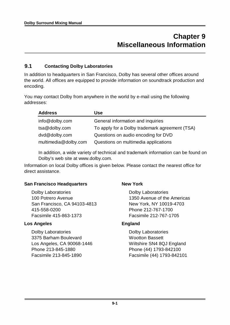
Dolby Surround Mixing Manual
9-1
Chapter 9Miscellaneous Information
9.1 Contacting Dolby Laboratories
In addition to headquarters in San Francisco, Dolby has several other offices aroundthe world. All offices are equipped to provide information on soundtrack production andencoding.
You may contact Dolby from anywhere in the world by e-mail using the followingaddresses:
Address Use
[email protected] General information and inquiries
[email protected] To apply for a Dolby trademark agreement (TSA)
[email protected] Questions on audio encoding for DVD
[email protected] Questions on multimedia applications
In addition, a wide variety of technical and trademark information can be found onDolby’s web site at www.dolby.com.
Information on local Dolby offices is given below. Please contact the nearest office fordirect assistance.
San Francisco Headquarters
Dolby Laboratories100 Potrero AvenueSan Francisco, CA 94103-4813415-558-0200Facsimile 415-863-1373
Los Angeles
Dolby Laboratories3375 Barham BoulevardLos Angeles, CA 90068-1446Phone 213-845-1880Facsimile 213-845-1890
New York
Dolby Laboratories1350 Avenue of the AmericasNew York, NY 10019-4703Phone 212-767-1700Facsimile 212-767-1705
England
Dolby LaboratoriesWootton BassettWiltshire SN4 8QJ EnglandPhone (44) 1793-842100Facsimile (44) 1793-842101
Dolby Surround Mixing Manual Chapter 9 - Mi scellaneous Information
9-2
Shanghai Liaison Office
Dolby Laboratories Representative Office5/Fl. Hai Xing Plaza, Unit GRui Jin Road (S)Shanghai 2000023 ChinaPhone (86) 21-6418-1015Facsimile (86) 21-6418-1013
Japanese Liaison Office
Dolby Laboratories InternationalServices, Inc.Japan BranchFuji Chuo Building 6F2-1-7, Shintomi, Chuo-kuTokyo 104-0041 JapanPhone (81) 3-5542-6160Facsimile (81) 3-5542-6158
CFE PRO
Roppongi OfficeSaski Building 18-9Roppongi 3 ChomeMinato-ku, Tokyo 106-0032 JapanPhone (81) 3-583-84515Facsimile (81) 3-589-0272
9.2 Software Identification and Trademark Usage
Dolby Laboratories encourages use of the Dolby Surround trademark to identifysoundtracks that are encoded in Dolby Surround. This is an effective way to informlisteners of the soundtrack format, and the use of a standard logo promotes easyrecognition in the marketplace. However, like any trademark, the Dolby Surround logomay not be used without permission. Dolby Laboratories therefore provides a royalty-free Trademark and Standardization Agreement (TSA) for companies who wish to useDolby trademarks. This agreement must be signed by the company that owns theprogram material being produced. Recording studios or production facilities thatprovide audio production, encoding, or manufacturing services for outside clientsgenerally do not require a trademark license. However, we do ask that these facilitiesrefer their clients to us for trademark licensing information.
If you would like to use the Dolby Surround logo you can apply for a Dolby Trademarkand Standardization Agreement (TSA) by sending e-mail to [email protected] or bycontacting Dolby Laboratories at any of the locations given in Section 9.1 ContactingDolby Laboratories. When sending written requests please indicate that you would likea Dolby Surround trademark license and include your name, your company name,mailing address, and the type of media on which your soundtracks will be distributed,such as CD, laser disc or VHS.
For detailed information on Dolby trademark licensing, please refer to the documentUse of Dolby Trademarks on Audio and Video Media, available on the Dolby web siteat www.dolby.com. We are also planning to make our license application form availableon-line, so check the Dolby web site in the coming months for the on-line version of theMedia Licensing Questionnaire.
Dolby Surround Mixing Manual Chapter 9 - Mi scellaneous Information
9-3
If you are already a Dolby licensee and would like more information on trademark use,please contact Dolby Laboratories. We are always happy to review artwork and assistwith the proper use of our trademarks. Information on trademark licensing plusinstructions for using the Dolby Surround trademark and marking audio features onDVD can also be found on the Dolby web site.
9.3 Dolby Surround Consultants
Dolby Laboratories has consultants available to assist with setting up rooms, checkingcalibrations, and mixing. Consultants are available for a fee for either half or full days.Charges for engineering services do not include travel to and from the studio. If thefacility is outside of the local area for one of our offices, travel, hotel and meals will beadded at actual cost.
9.4 Dolby Surround Software Lists
To let consumers know what programs, CDs, games and videos are available withDolby Surround encoding, Dolby Laboratories maintains listings on the Dolby WebPage (www.dolby.com) and in print. In order to keep these lists current, studios andengineers producing Dolby Surround encoded programs are encouraged to give usinformation on their titles for inclusion on these lists. Program information can be sentto [email protected].