Embed Size (px)
Citation preview
Dolby Atmos Production SuiteGuide
Software version 2.5.121 April 2017Confidential information
Copyright© 2017 Dolby Laboratories. All rights reserved.
Dolby Laboratories, Inc.1275 Market StreetSan Francisco, CA 94103-1410 USATelephone 415-558-0200Fax 415-863-1373http://www.dolby.com
TrademarksDolby and the double-D symbol are registered trademarks of Dolby Laboratories.
The following are trademarks of Dolby Laboratories:
Dialogue Intelligence™
Dolby®
Dolby Advanced Audio™
Dolby Atmos®
Dolby Audio™
Dolby Cinema™
Dolby Digital Plus™
Dolby Digital Plus Advanced Audio™
Dolby Digital Plus Home Theater™
Dolby Home Theater®
Dolby Theatre®
Dolby Vision™
Dolby Voice®
Feel Every Dimension™
Feel Every Dimension in Dolby™
Feel Every Dimension in Dolby Atmos™
MLP Lossless™
Pro Logic®
Surround EX™
All other trademarks remain the property of their respective owners.
PatentsThis product is protected by one or more patents in the United States and elsewhere. Formore information, including a specific list of patents protecting this product, please visit http://www.dolby.com/patents.
Contents
1 Introduction to the Dolby Atmos Production Suite guide 91.1 About this documentation 91.2 Channel abbreviations 91.3 Contacting Dolby 9
2 Introduction to the Dolby Atmos Production Suite 112.1 Dolby Atmos Production Suite installer components 112.2 How the Dolby Atmos Production Suite components work together 12
2.2.1 Object tracks with Dolby Atmos Production Suitepanner plug-ins 12
2.2.2 Bed tracks 132.2.3 Bed and object audio sent to the Renderer inputs (via Dolby
Renderer Send plug-ins) 132.2.4 Renderer output signal returned to Pro Tools (via Dolby
Renderer Return plug-ins), and then routed to ProTools outputs 13
3 Installing the Dolby Atmos Production Suite main components 143.1 System requirements 143.2 Activating your Dolby Atmos Rendering and Mastering license 143.3 Installing the Dolby Atmos Production Suite required components 153.4 Establishing communication between the Dolby Atmos Renderer
and Pro Tools 163.5 Launching the Dolby Atmos Renderer and supporting software 183.6 Selecting an operation mode 193.7 Considerations when opening Pro Tools sessions authored with
older panner plug-ins 203.8 Workflows for converting home theater and VR mixes 21
3.8.1 Converting a home theater session to a VR session that usesthe Dolby Atmos VR XYZ Panner 21
3.8.2 Converting a VR session that uses the Dolby Atmos VR XYZPanner to a home theater session 22
4 Dolby Atmos workflow overview 234.1 Dolby Atmos mix overview 234.2 Authoring in Dolby Atmos 234.3 Working with beds 244.4 Working with objects 254.5 Considerations for hearing Dolby Atmos audio 254.6 Playing back audio with a Dolby Atmos session template 26
5 Setting up a Pro Tools session for Dolby Atmos 275.1 Pro Tools session configured for Dolby Atmos rendering
and mastering 275.1.1 Session requirements 275.1.2 Track, plug-in, and routing configuration requirements 27
5.2 Session templates supplied by Dolby and configuredfor Dolby Atmos 285.2.1 Session template locations and names 285.2.2 Session template specifications 29
Confidential information Contents
Dolby Atmos Production Suite software version 2.5.1 guide
21 April 2017 3
5.3 Creating a Pro Tools session from the template supplied by Dolby 295.4 Creating your own Pro Tools session for Dolby Atmos 30
5.4.1 Considerations when inserting panner plug-ins in Pro Tools 345.5 Channel assignments for Dolby Atmos plug-ins 355.6 Manually assigning an input channel number 365.7 Inserting multiple panner plug-ins and automatically
assigning channels 365.7.1 Autoassign options 37
6 Positioning objects in a Dolby Atmos mix 386.1 Automating panner controls 386.2 Panner automatable controls 39
6.2.1 Dolby Atmos Panner automatable controls 396.2.2 Dolby Atmos VR Spherical Panner automatize controls 396.2.3 Dolby Atmos VR XYZ Panner automatable controls 40
6.3 Changing object location 406.4 Positioning tasks specific to Home Theater workflows 41
6.4.1 Using Elevation mode 416.4.2 Elevation snap modes 426.4.3 Using ceiling elevation 426.4.4 Using sphere elevation 426.4.5 Using wedge elevation 436.4.6 Using Speaker Snap mode 436.4.7 Managing speaker zones 446.4.8 Changing object size 456.4.9 Z coordinate and Dolby Atmos Panner controls 45
6.5 Positioning tasks specific to VR workflows 466.5.1 Setting how panning volume models the placement
of objects 466.5.2 Setting how sound tracks to head movements 46
7 Managing Production Suite panner plug-ins 487.1 Bypassing panner plug-in metadata 487.2 Accessing panner configuration options 487.3 Changing the view of a Dolby Atmos VR panner 497.4 Resizing a panner plug-in window 507.5 Linking stereo panner plug-in controls 50
8 Controlling Production Suite panner plug-ins with different hardware52
8.1 Using a mouse to position an object 528.2 Using a keyboard to position an object 528.3 Panning with a supported JLCooper controller 52
8.3.1 Dolby Atmos Panner and JLCooper joystick switch andknob reference 53
8.3.2 Dolby Atmos VR Spherical Panner and JLCooper joystickswitch and knob reference 54
8.3.3 Dolby Atmos VR XYZ Panner and JLCooper joystick switchand knob reference 54
8.3.4 Installing and configuring a JLCooper MCS-Panner joystick 548.3.5 Preparing to use the JLCooper Axos 558.3.6 Installing the JLCooper Eclipse PX joystick 568.3.7 Configuring a JLCooper Eclipse PX joystick in a panner plug-in
57
Confidential information Contents
Dolby Atmos Production Suite software version 2.5.1 guide
21 April 2017 4
8.4 Control surface and mixing console support 578.5 Generic MIDI support 58
9 Rendering to the Dolby Atmos format 609.1 Overview of rendering 609.2 Live monitoring a Dolby Atmos mix 609.3 Playing back a master or other Dolby Atmos media file 61
10 Recording Dolby Atmos content 6310.1 Recording a bounded master 6310.2 Recording an unbounded master 6510.3 Punching in and out of a master recording at set points 6710.4 Punching in and out of a master recording manually 6810.5 Paths and file names for a master file set 6910.6 Deleting master media 70
11 Re-rendering to channel-based formats 7111.1 Re-render output matrix 7111.2 Configuring the re-render output matrix 73
11.2.1 Edit mode 7611.2.2 Clearing a re-render strip 76
11.3 Recording re-renders in real time 7611.4 Creating re-renders offline 77
12 Customizing the Renderer 8012.1 Overview for customizing your Renderer 80
12.1.1 Selecting an operation mode 8012.1.2 Setting up the physical layout for your room 8012.1.3 Creating or changing a custom monitoring layout 8112.1.4 Room equalization for monitoring 8312.1.5 Creating or changing an equalization preset 83
12.2 Editing a custom equalization preset 8612.2.1 Opening a custom EQ preset for editing 8712.2.2 Selecting a speaker feed to equalize 8812.2.3 Generating a signal to a specific speaker 8912.2.4 Panning pink noise through each channel sequentially 9012.2.5 Generating signal to a single speaker 9112.2.6 Managing all output levels 9212.2.7 Copying speaker equalization settings 9312.2.8 Adjusting the level of bass and treble frequencies 9512.2.9 Adjusting the level of individual frequencies 9612.2.10 Editing the overall output level of a speaker 97
12.3 Editing expert settings in the settings screen 9712.3.1 Adjusting the speakers pre-EQ gain (dB) for
headroom optimization 9812.3.2 Setting the global audio delay (ms) 98
13 Configuring your inputs 9913.1 Editing and saving input routing and group assignments 9913.2 Multiple beds 103
14 Managing custom groups 10514.1 Group management overview 10514.2 Creating groups for re-rendering 105
Confidential information Contents
Dolby Atmos Production Suite software version 2.5.1 guide
21 April 2017 5
14.3 Editing a group name 10614.4 Deleting a group 10714.5 Viewing groups in Read Only mode 108
15 Managing I/O configurations 11015.1 I/O configuration file 11015.2 Loading an I/O configuration 110
15.2.1 Loading both the input and output configurations 11015.2.2 Loading the input configuration only 11115.2.3 Loading the output configuration only 112
15.3 Saving an I/O configuration as a file 11315.4 Clearing an input or output configuration 11415.5 Resetting an input or output table to the system default I/O 11415.6 Expanding or collapsing I/O screen elements 115
16 Managing Renderer input and output levels from the Monitor application116
16.1 Muting Renderer input beds and objects 11616.2 Dimming Renderer audio output 11616.3 Changing the gain of Renderer audio output 11716.4 Muting Renderer audio output 11716.5 Generating pink noise to a speaker 117
17 Managing system settings and maintenance 11917.1 Selecting an operation mode 11917.2 Rendering and mastering software system settings 11917.3 Backing up system settings 12117.4 Restoring (loading) system settings 12117.5 Resetting system settings 12117.6 Troubleshooting 122
17.6.1 Accessing Renderer processing information 12217.6.2 Log menu and screen 12217.6.3 Log screen displays and options 123
18 Working with Dolby Atmos monitor meters and displays 12418.1 Selecting a Monitor application view 12418.2 Bed and object monitoring 125
18.2.1 Input status indicators 12618.2.2 Viewing the input status indicators 12718.2.3 Objects view 12718.2.4 Displaying objects view 12918.2.5 Modifying objects view 129
18.3 Considerations when monitoring Renderer outputs 13118.4 Room configuration display 131
18.4.1 Viewing the room configuration and speakers 13218.5 Clearing clips in the Renderer output meters 132
19 Dolby Atmos Renderer UI 13319.1 Dolby Atmos Renderer screen organization 133
19.1.1 Status and control section 13319.1.2 Navigation bar 135
19.2 Menu screens 13519.2.1 Monitoring screen 13519.2.2 Mastering screen 139
Confidential information Contents
Dolby Atmos Production Suite software version 2.5.1 guide
21 April 2017 6
19.2.3 Input and output screens 14119.2.4 Common I/O screen controls and buttons 14119.2.5 Controls and buttons specific to the input screen 14319.2.6 Controls and buttons specific to the output screen 14619.2.7 Settings screen 14919.2.8 Equalization screen 15019.2.9 Room screen 15219.2.10 Maintenance screen 15419.2.11 Log screen 155
20 Dolby Atmos Panner plug-in UI 15720.1 Dolby Atmos Panner virtual room 15720.2 Operation mode buttons and zones selector 15820.3 X/Y/Z sliders and position displays 159
20.3.1 Elevation and Z coordinate user-interface elements 15920.4 Object size slider and value display 15920.5 UI elements common to Production Suite panner plug-ins 162
20.5.1 Object drop-down menu 16320.5.2 Configuration options button 16320.5.3 Configuration options area 16320.5.4 Stereo panner Linking selector 16620.5.5 Resize window control 166
21 Dolby Atmos VR Spherical Panner plug-in UI 16721.1 Dolby Atmos VR Spherical Panner views 16721.2 Binaural and head-tracking controls 16821.3 θ/φ/ρ spherical sliders and position displays 16921.4 UI elements common to Production Suite panner plug-ins 170
21.4.1 Object drop-down menu 17021.4.2 Configuration options button 17021.4.3 Configuration options area 17121.4.4 Stereo panner Linking selector 17321.4.5 Resize window control 173
22 Dolby Atmos VR XYZ Panner plug-in UI 17422.1 Dolby Atmos VR XYZ Panner views 17422.2 Binaural and head-tracking controls 17522.3 X/Y/Z sliders and position displays 17622.4 UI elements common to Production Suite panner plug-ins 176
22.4.1 Object drop-down menu 17622.4.2 Configuration options button 17722.4.3 Configuration options area 17722.4.4 Stereo panner Linking selector 17922.4.5 Resize window control 180
23 Dolby Renderer Send and Return plug-ins UI 18123.1 Dolby Renderer Send and Return plug-in user interface 18123.2 General use of the Dolby Atmos Renderer plug-ins in Pro Tools 182
24 Dolby Atmos Monitor application UI 18324.1 Dolby Atmos Monitor overview 18324.2 Monitor application window header 184
24.2.1 Renderer section 18424.2.2 Monitor Mode section 185
Confidential information Contents
Dolby Atmos Production Suite software version 2.5.1 guide
21 April 2017 7
24.2.3 Time section 18624.2.4 Transport section 18624.2.5 Dim section 18624.2.6 Mute section 18624.2.7 Attenuation section 18624.2.8 View section 187
24.3 Audio CPU usage indication 18724.4 Signal Generator section 18724.5 Monitor application keyboard shortcuts reference 188
25 Technology overviews 18925.1 Dolby Atmos master file set 18925.2 Dolby Atmos media files 18925.3 Spatial coding 189
25.3.1 Introduction 19025.3.2 What is spatial coding 19025.3.3 Spatial coding in the authoring chain 19125.3.4 Spatial coding configuration 19225.3.5 Spatial coding limitations and fine tuning 192
Glossary 194
Confidential information Contents
Dolby Atmos Production Suite software version 2.5.1 guide
21 April 2017 8
1 Introduction to the Dolby AtmosProduction Suite guideThis documentation describes how to set up and use the Dolby Atmos Production Suite tocreate and work with Dolby Atmos content in Avid Pro Tools.
• About this documentation• Channel abbreviations• Contacting Dolby
1.1 About this documentationThis documentation provides information for using the Dolby Atmos Renderer and otherDolby Atmos software to create or play back a Dolby Atmos master, listen to a Dolby Atmosmix, and pan audio objects in a Dolby Atmos mix.
This documentation is for engineers and sound designers who author Dolby Atmos soundand create Dolby Atmos masters.
1.2 Channel abbreviationsThis documentation uses several channel abbreviations.
Abbreviation Channel
L Left
R Right
C Center
LFE Low-Frequency Effects
S Mono Surround
Ls Left Surround
Rs Right Surround
Lss Left side surround
Rss Right side surround
Lrs * Left Rear Surround
Rrs * Right Rear Surround
Lts Left Top Surround
Rts Right Top Surround
* Lrs and Rrs correspond to Pro Tools Lsr and Rsr abbreviations.
1.3 Contacting DolbyYou can contact Dolby regarding documentation.
Confidential information Introduction to the Dolby Atmos Production Suite guide
Dolby Atmos Production Suite software version 2.5.1 guide
21 April 2017 9
If you have questions or comments about this document, please send an email to [email protected].
Confidential information Introduction to the Dolby Atmos Production Suite guide
Dolby Atmos Production Suite software version 2.5.1 guide
21 April 2017 10
2 Introduction to the Dolby AtmosProduction SuiteThe Dolby Atmos Production Suite package includes the Dolby Atmos Production Suiteinstaller, which provides the software applications and plug-ins required to mix and recordDolby Atmos content.
• Dolby Atmos Production Suite installer components• How the Dolby Atmos Production Suite components work together
2.1 Dolby Atmos Production Suite installercomponentsThe Dolby Atmos Production Suite installer provides the software applications and plug-insrequired to mix and record Dolby Atmos content. These software components work with ProTools in a Dolby Atmos authoring environment.
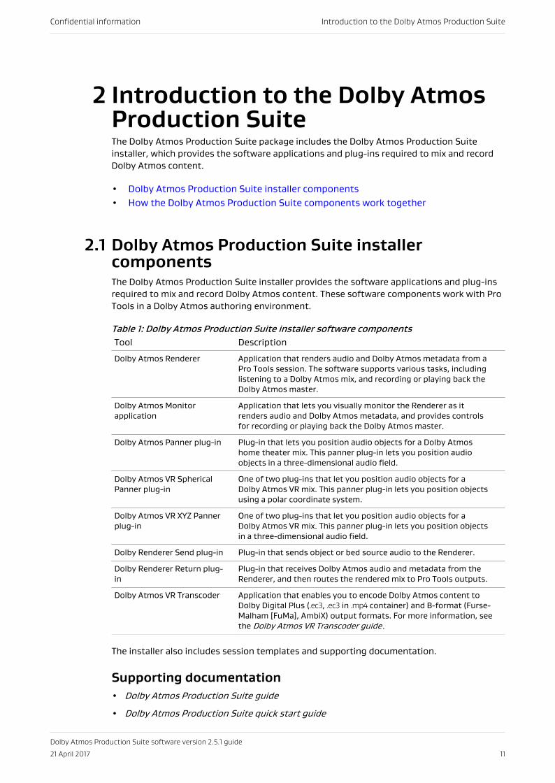
Table 1: Dolby Atmos Production Suite installer software componentsTool Description
Dolby Atmos Renderer Application that renders audio and Dolby Atmos metadata from aPro Tools session. The software supports various tasks, includinglistening to a Dolby Atmos mix, and recording or playing back theDolby Atmos master.
Dolby Atmos Monitorapplication
Application that lets you visually monitor the Renderer as itrenders audio and Dolby Atmos metadata, and provides controlsfor recording or playing back the Dolby Atmos master.
Dolby Atmos Panner plug-in Plug-in that lets you position audio objects for a Dolby Atmoshome theater mix. This panner plug-in lets you position audioobjects in a three-dimensional audio field.
Dolby Atmos VR SphericalPanner plug-in
One of two plug-ins that let you position audio objects for aDolby Atmos VR mix. This panner plug-in lets you position objectsusing a polar coordinate system.
Dolby Atmos VR XYZ Pannerplug-in
One of two plug-ins that let you position audio objects for aDolby Atmos VR mix. This panner plug-in lets you position objectsin a three-dimensional audio field.
Dolby Renderer Send plug-in Plug-in that sends object or bed source audio to the Renderer.
Dolby Renderer Return plug-in
Plug-in that receives Dolby Atmos audio and metadata from theRenderer, and then routes the rendered mix to Pro Tools outputs.
Dolby Atmos VR Transcoder Application that enables you to encode Dolby Atmos content toDolby Digital Plus (.ec3, .ec3 in .mp4 container) and B-format (Furse-Malham [FuMa], AmbiX) output formats. For more information, seethe Dolby Atmos VR Transcoder guide.
The installer also includes session templates and supporting documentation.
Supporting documentation• Dolby Atmos Production Suite guide
• Dolby Atmos Production Suite quick start guide
Confidential information Introduction to the Dolby Atmos Production Suite
Dolby Atmos Production Suite software version 2.5.1 guide
21 April 2017 11
• Dolby Atmos Production Suite release notes
• Dolby Atmos VR Transcoder guide
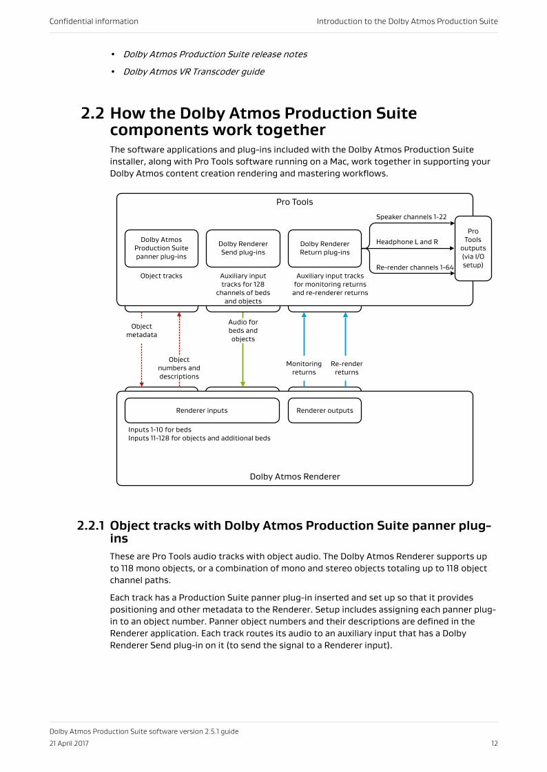
2.2 How the Dolby Atmos Production Suitecomponents work togetherThe software applications and plug-ins included with the Dolby Atmos Production Suiteinstaller, along with Pro Tools software running on a Mac, work together in supporting yourDolby Atmos content creation rendering and mastering workflows.
Dolby Atmos Renderer
Pro Tools
Dolby Atmos Production Suite panner plug-ins
Dolby Renderer Send plug-ins
Speaker channels 1-22
Headphone L and R
Re-render channels 1-64
Pro Tools
outputs (via I/O setup)
Renderer inputs
Object numbers and descriptions
Object metadata
Audio for beds and objects
Monitoring returns
Renderer outputs
Dolby Renderer Return plug-ins
Inputs 1-10 for bedsInputs 11-128 for objects and additional beds
Object tracks Auxiliary input tracks for 128
channels of beds and objects
Re-render returns
Auxiliary input tracks for monitoring returns
and re-renderer returns
2.2.1 Object tracks with Dolby Atmos Production Suite panner plug-insThese are Pro Tools audio tracks with object audio. The Dolby Atmos Renderer supports upto 118 mono objects, or a combination of mono and stereo objects totaling up to 118 objectchannel paths.
Each track has a Production Suite panner plug-in inserted and set up so that it providespositioning and other metadata to the Renderer. Setup includes assigning each panner plug-in to an object number. Panner object numbers and their descriptions are defined in theRenderer application. Each track routes its audio to an auxiliary input that has a DolbyRenderer Send plug-in on it (to send the signal to a Renderer input).
Confidential information Introduction to the Dolby Atmos Production Suite
Dolby Atmos Production Suite software version 2.5.1 guide
21 April 2017 12
2.2.2 Bed tracksThese are Pro Tools audio tracks with bed material. In a basic Dolby Atmos setup, this is a 7.1multichannel track and stereo overhead track.
Each track routes its audio to an auxiliary input that has a Dolby Renderer Send plug-in on it(to send the signal to a Renderer input).
2.2.3 Bed and object audio sent to the Renderer inputs (via DolbyRenderer Send plug-ins)For Dolby Atmos rendering, each bed and object track requires an auxiliary input track withone Dolby Renderer Send plug-in inserted on it and configured for a Renderer input channel.
Each track receives audio from a Dolby Atmos object or bed track output bus, and then sendsthe material to the Renderer (via a Dolby Renderer Send plug-in on the track).
2.2.4 Renderer output signal returned to Pro Tools (via DolbyRenderer Return plug-ins), and then routed to Pro ToolsoutputsFor monitoring Dolby Atmos rendered outputs (or playing back a master), each Rendereroutput requires an auxiliary input track with a Dolby Renderer Return plug-in inserted on itand configured for a Renderer output channel.
Each track receives audio from a Renderer output (via a Dolby Renderer Return plug-in on thetrack), and then uses an output bus to send the material to an auxiliary input track thatroutes the audio to a Pro Tools output:
• A stereo auxiliary input track returns the rendered binaural Dolby Atmos audio from theDolby Atmos Renderer, and sends it to an auxiliary input track for headphone Left andRight output in Pro Tools.
• Up to 22 mono auxiliary input tracks return rendered speaker audio from the Renderer,and send it to auxiliary input tracks for speaker outputs in Pro Tools.
• Up to 64 mono auxiliary input tracks return re-rendered audio from the Renderer, andsend it to auxiliary tracks for re-renderer outputs in Pro Tools.
Confidential information Introduction to the Dolby Atmos Production Suite
Dolby Atmos Production Suite software version 2.5.1 guide
21 April 2017 13
3 Installing the Dolby AtmosProduction Suite maincomponentsInstall the Dolby Atmos Production Suite main components on your Pro Tools workstation.The installer includes the Dolby Atmos Renderer, Dolby Atmos plug-ins, and the Dolby AtmosMonitor application.
• System requirements• Activating your Dolby Atmos Rendering and Mastering license• Installing the Dolby Atmos Production Suite required components• Establishing communication between the Dolby Atmos Renderer and Pro Tools• Launching the Dolby Atmos Renderer and supporting software• Selecting an operation mode• Considerations when opening Pro Tools sessions authored with older panner plug-
ins• Workflows for converting home theater and VR mixes
3.1 System requirementsBefore installing Dolby Atmos Production Suite, ensure that your system configurationmeets the requirements.
Dolby Atmos Production Suite has been tested in these configurations:
Pro Tools version Mac OS X system
12.7 10.12
12.5.2 10.11.6
3.2 Activating your Dolby Atmos Rendering andMastering licenseActivate your Dolby Rendering and Mastering license to use the Dolby Atmos ProductionSuite. We recommend that you activate your license before you install the Production Suite.
Prerequisites
• Download the iLok License Manager from www.ilok.com.
• Ensure that you have iLok authorization for Dolby Rendering and Mastering.
About this task
This task is performed in the iLok License Manager.
The Dolby Rendering and Mastering license includes an authorization for the Dolby AtmosRenderer software, and the Dolby Renderer Send and Return plug-ins.
Confidential information Installing the Dolby Atmos Production Suite main components
Dolby Atmos Production Suite software version 2.5.1 guide
21 April 2017 14
Procedure
1. Launch the iLok License Manager.
2. In the iLok License Manager window, sign in to your account, and then click (highlight)your account name in the navigation bar.
Your account name is shown in the upper-left panel. Your host machine and iLokUniversal Serial Bus (USB) devices are shown as icons in the panel below your accountinformation.
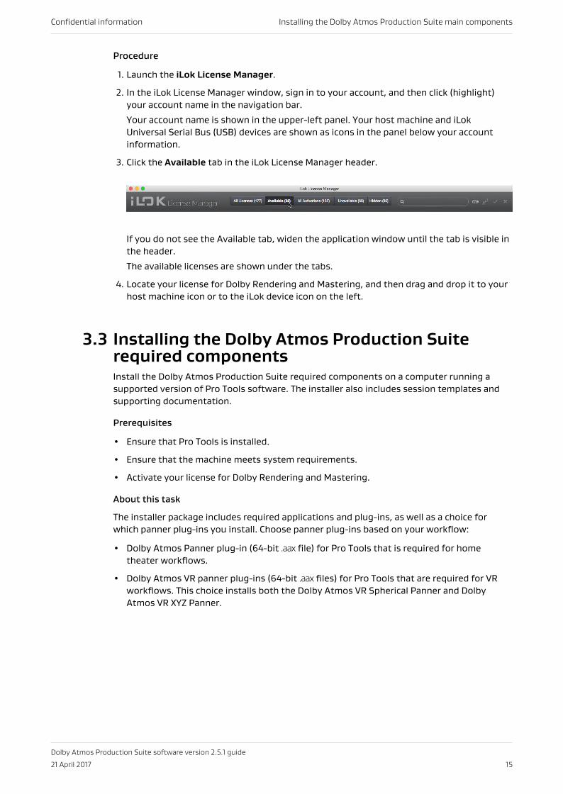
3. Click the Available tab in the iLok License Manager header.
If you do not see the Available tab, widen the application window until the tab is visible inthe header.
The available licenses are shown under the tabs.
4. Locate your license for Dolby Rendering and Mastering, and then drag and drop it to yourhost machine icon or to the iLok device icon on the left.
3.3 Installing the Dolby Atmos Production Suiterequired componentsInstall the Dolby Atmos Production Suite required components on a computer running asupported version of Pro Tools software. The installer also includes session templates andsupporting documentation.
Prerequisites
• Ensure that Pro Tools is installed.
• Ensure that the machine meets system requirements.
• Activate your license for Dolby Rendering and Mastering.
About this task
The installer package includes required applications and plug-ins, as well as a choice forwhich panner plug-ins you install. Choose panner plug-ins based on your workflow:
• Dolby Atmos Panner plug-in (64-bit .aax file) for Pro Tools that is required for hometheater workflows.
• Dolby Atmos VR panner plug-ins (64-bit .aax files) for Pro Tools that are required for VRworkflows. This choice installs both the Dolby Atmos VR Spherical Panner and DolbyAtmos VR XYZ Panner.
Confidential information Installing the Dolby Atmos Production Suite main components
Dolby Atmos Production Suite software version 2.5.1 guide
21 April 2017 15
Procedure
1. Quit Pro Tools if it is running.
2. If updating Dolby Atmos Renderer and supporting software, ensure the Dolby AtmosMonitor application and the Dolby Atmos Renderer are not running.
3. Double-click the Dolby Atmos Production Suite installer package (Dolby Atmos ProductionSuite-2.5.1.pkg).
4. Follow the onscreen instructions.
5. Complete installation.
Results
• All items selected for installation are installed.
• When you install the Dolby Atmos Renderer, templates automatically install in the ProTools session templates folder:
• Home theater templates: ~/Documents/Pro Tools/Session Templates/Dolby Atmos ProductionSuite
• VR templates: ~/Documents/Pro Tools/Session Templates/Dolby Atmos VR Production Suite
• When you install documentation, the documentation set is installed on your local drive at~/Documents/Dolby/Dolby Atmos Renderer Production Suite.
What to do next
• Establish communication between the Dolby Atmos Renderer and Pro Tools.
• If you are planning to work with VR content, install the Dolby Atmos VR Player on aqualified device. Refer to documentation included with the player. You can download theDolby Atmos VR Player installer along with the Dolby Atmos VR Player guide from www.dolby.com/vrtools.
3.4 Establishing communication between the DolbyAtmos Renderer and Pro ToolsStart and configure the Dolby Atmos Monitor application to enable communication betweenthe Dolby Atmos Renderer and Pro Tools.
About this taskYou only need to perform this task the first time you use the Dolby Atmos Renderer andMonitor application (or if you subsequently change the Internet Protocol (IP) address or hostname in the Dolby Atmos Monitor).
The Dolby Atmos Renderer and the Dolby Atmos Monitor application are located in theApplications/Dolby folder.
Procedure
1. Click the Dolby Atmos Renderer icon to launch the renderer.
Confidential information Installing the Dolby Atmos Production Suite main components
Dolby Atmos Production Suite software version 2.5.1 guide
21 April 2017 16
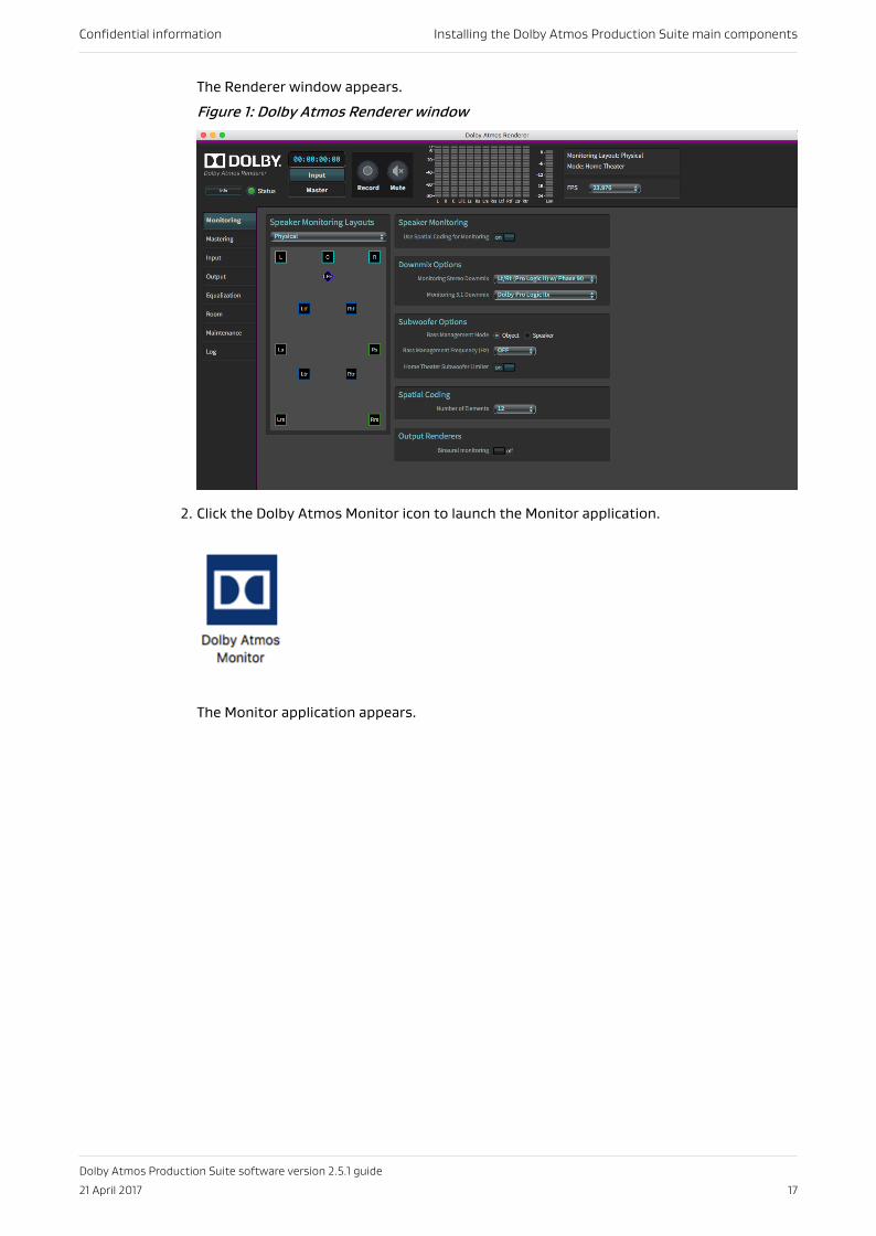
The Renderer window appears.
Figure 1: Dolby Atmos Renderer window
2. Click the Dolby Atmos Monitor icon to launch the Monitor application.
The Monitor application appears.
Confidential information Installing the Dolby Atmos Production Suite main components
Dolby Atmos Production Suite software version 2.5.1 guide
21 April 2017 17
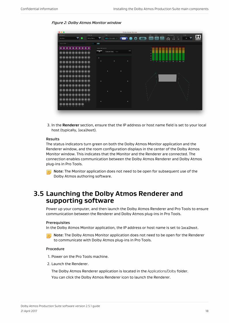
Figure 2: Dolby Atmos Monitor window
3. In the Renderer section, ensure that the IP address or host name field is set to your localhost (typically, localhost).
ResultsThe status indicators turn green on both the Dolby Atmos Monitor application and theRenderer window, and the room configuration displays in the center of the Dolby AtmosMonitor window. This indicates that the Monitor and the Renderer are connected. Theconnection enables communication between the Dolby Atmos Renderer and Dolby Atmosplug-ins in Pro Tools.
Note: The Monitor application does not need to be open for subsequent use of theDolby Atmos authoring software.
3.5 Launching the Dolby Atmos Renderer andsupporting softwarePower up your computer, and then launch the Dolby Atmos Renderer and Pro Tools to ensurecommunication between the Renderer and Dolby Atmos plug-ins in Pro Tools.
PrerequisitesIn the Dolby Atmos Monitor application, the IP address or host name is set to localhost.
Note: The Dolby Atmos Monitor application does not need to be open for the Rendererto communicate with Dolby Atmos plug-ins in Pro Tools.
Procedure
1. Power on the Pro Tools machine.
2. Launch the Renderer.
The Dolby Atmos Renderer application is located in the Applications/Dolby folder.
You can click the Dolby Atmos Renderer icon to launch the Renderer.
Confidential information Installing the Dolby Atmos Production Suite main components
Dolby Atmos Production Suite software version 2.5.1 guide
21 April 2017 18
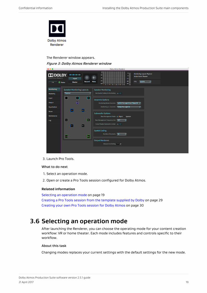
The Renderer window appears.
Figure 3: Dolby Atmos Renderer window
3. Launch Pro Tools.
What to do next
1. Select an operation mode.
2. Open or create a Pro Tools session configured for Dolby Atmos.
Related information
Selecting an operation mode on page 19Creating a Pro Tools session from the template supplied by Dolby on page 29Creating your own Pro Tools session for Dolby Atmos on page 30
3.6 Selecting an operation modeAfter launching the Renderer, you can choose the operating mode for your content creationworkflow: VR or home theater. Each mode includes features and controls specific to theirworkflow.
About this task
Changing modes replaces your current settings with the default settings for the new mode.
Confidential information Installing the Dolby Atmos Production Suite main components
Dolby Atmos Production Suite software version 2.5.1 guide
21 April 2017 19
Procedure
1. Choose Maintenance in the navigation bar to open the maintenance screen.
2. In the Mode section, perform one of these steps:
• For VR content creation, click (check) VR.
• For home theater content creation, click (check) Home Theater.
3. For access to the Settings menu and additional Monitoring controls, click Expert.
3.7 Considerations when opening Pro Tools sessionsauthored with older panner plug-insWhen you open a Pro Tools session that was authored with versions of panner plug-ins priorto Dolby Atmos Production Suite panner plug-ins, how the session opens is dependent onthe version of the older plug-in, as well as which Dolby Atmos Production Suite panner plug-ins are installed on your system.
Table 2: Session behavior and panner usage when opening sessions authored with olderpanner plug-insPanner used in originalauthoring session
Panners installed with DolbyAtmos Production Suite
Session behavior and pannerusage when session isopened with Dolby AtmosProduction Suite
Dolby Atmos Panner v1.6.3 orearlier (that is, for a non-VRsession)
Dolby Atmos Panner or allthree Production Suite pannerplug-ins
Opens using a newer versionof the Dolby Atmos Panner.
Dolby Atmos Panner v1.6.3 orearlier (that is, for a non-VRsession)
Dolby Atmos VR panners Opens using the Dolby AtmosVR XYZ Panner in top-downcube view, and maps the X, Y,and Z parameters to the X, Y,and Z parameters in the DolbyAtmos VR XYZ Panner. DolbyAtmos VR XYZPannerautomation data thatcannot be mapped is removed.Additionally, an error dialogappears in the Renderer,alerting you that somemetadata is being ignored dueto the change in plug-ins.
Confidential information Installing the Dolby Atmos Production Suite main components
Dolby Atmos Production Suite software version 2.5.1 guide
21 April 2017 20
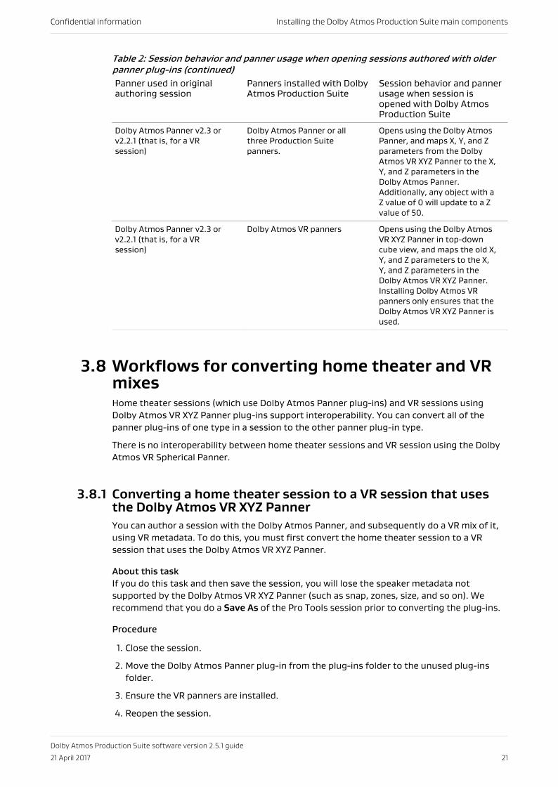
Table 2: Session behavior and panner usage when opening sessions authored with olderpanner plug-ins (continued)Panner used in originalauthoring session
Panners installed with DolbyAtmos Production Suite
Session behavior and pannerusage when session isopened with Dolby AtmosProduction Suite
Dolby Atmos Panner v2.3 orv2.2.1 (that is, for a VRsession)
Dolby Atmos Panner or allthree Production Suitepanners.
Opens using the Dolby AtmosPanner, and maps X, Y, and Zparameters from the DolbyAtmos VR XYZ Panner to the X,Y, and Z parameters in theDolby Atmos Panner.Additionally, any object with aZ value of 0 will update to a Zvalue of 50.
Dolby Atmos Panner v2.3 orv2.2.1 (that is, for a VRsession)
Dolby Atmos VR panners Opens using the Dolby AtmosVR XYZ Panner in top-downcube view, and maps the old X,Y, and Z parameters to the X,Y, and Z parameters in theDolby Atmos VR XYZ Panner.Installing Dolby Atmos VRpanners only ensures that theDolby Atmos VR XYZ Panner isused.
3.8 Workflows for converting home theater and VRmixesHome theater sessions (which use Dolby Atmos Panner plug-ins) and VR sessions usingDolby Atmos VR XYZ Panner plug-ins support interoperability. You can convert all of thepanner plug-ins of one type in a session to the other panner plug-in type.
There is no interoperability between home theater sessions and VR session using the DolbyAtmos VR Spherical Panner.
3.8.1 Converting a home theater session to a VR session that usesthe Dolby Atmos VR XYZ PannerYou can author a session with the Dolby Atmos Panner, and subsequently do a VR mix of it,using VR metadata. To do this, you must first convert the home theater session to a VRsession that uses the Dolby Atmos VR XYZ Panner.
About this taskIf you do this task and then save the session, you will lose the speaker metadata notsupported by the Dolby Atmos VR XYZ Panner (such as snap, zones, size, and so on). Werecommend that you do a Save As of the Pro Tools session prior to converting the plug-ins.
Procedure
1. Close the session.
2. Move the Dolby Atmos Panner plug-in from the plug-ins folder to the unused plug-insfolder.
3. Ensure the VR panners are installed.
4. Reopen the session.
Confidential information Installing the Dolby Atmos Production Suite main components
Dolby Atmos Production Suite software version 2.5.1 guide
21 April 2017 21
The session opens with the X, Y, and Z parameters of Dolby Atmos Panner plug-insmapped to the X, Y, and Z parameters in Dolby Atmos VR XYZ Panner plug-ins. The pannerdisplays in top-down cube view.
5. Review each plug-in and add VR specific metadata, as desired.
6. Change the operation mode in the Renderer from Home Theater to VR.
3.8.2 Converting a VR session that uses the Dolby Atmos VR XYZPanner to a home theater sessionYou can author a session with the Dolby Atmos VR XYZ Panner, and subsequently do a hometheater (speaker) mix of it, using speaker metadata. To do this, you must first convert the VRsession to a home theater session that uses the Dolby Atmos Panner plug-in.
About this taskIf you do this task and then save the session, you will lose the speaker metadata notsupported by the Dolby Atmos Panner plug-in (such as binaural and head-tracking settings).We recommend that you do a Save As of the Pro Tools session prior to converting the plug-ins.
Procedure
1. Close the session.
2. Move the Dolby Atmos VR XYZ Panner plug-in from the plug-ins folder to the unusedplug-ins folder.
3. Ensure the Dolby Atmos Panner is installed.
4. Reopen the session.The session opens with the X, Y, and Z parameters of Dolby Atmos VR XYZ Panner plug-insmapped to the X, Y, and Z parameters in Dolby Atmos Panner plug-ins.
5. Review each plug-in and add home theater specific metadata, as desired.
6. Change the operation mode in the Renderer from VR to Home Theater.
Confidential information Installing the Dolby Atmos Production Suite main components
Dolby Atmos Production Suite software version 2.5.1 guide
21 April 2017 22
4 Dolby Atmos workflow overviewYou can author Dolby Atmos content in Pro Tools using a session that has been configuredfor Dolby Atmos.
• Dolby Atmos mix overview• Authoring in Dolby Atmos• Working with beds• Working with objects• Considerations for hearing Dolby Atmos audio• Playing back audio with a Dolby Atmos session template
4.1 Dolby Atmos mix overviewA Dolby Atmos mix consists of three primary elements: bed audio, object audio, andDolby Atmos metadata.
Bed audio (or bed material)Channel-based premixes or stems (including their multichannel panning)
Object audio (or objects)Mono or stereo soundtrack content that have dedicated panning (via Dolby Atmosmetadata)
Dolby Atmos metadataPanner automation for objects, plus additional metadata
4.2 Authoring in Dolby AtmosThe basic Dolby Atmos authoring workflow takes you from launching a Pro Tools sessionconfigured for Dolby Atmos to recording a master.
Prerequisites
1. The Dolby Atmos Production Suite installer components have been installed andconfigured on a machine running a qualified version of Pro Tools.
2. The Dolby Atmos Monitor application is set to localhost. It does not need to be open.
3. Make sure you have a Pro Tools session configured for Dolby Atmos.
• For home theater workflows, insert Dolby Atmos Panner plug-ins.
• For VR workflows, insert Dolby Atmos VR Spherical Panner and Dolby Atmos VR XYZPanner plug-ins, as needed.
Procedure
1. Launch the Dolby Atmos Renderer.
2. Ensure that the operation mode is set correctly in the maintenance menu by performingone of these steps:
• For home theater workflows, select Home Theater.
Confidential information Dolby Atmos workflow overview
Dolby Atmos Production Suite software version 2.5.1 guide
21 April 2017 23
• For VR workflows, select VR.
3. Launch a Pro Tools session configured for Dolby Atmos.
For example, his can be a session created from the template supplied by Dolby, or adifferent session that you created.
4. Add audio to the Dolby Atmos mix by adding audio to the Pro Tools bed and object tracks.
5. Listen to the Dolby Atmos mix by starting playback in Pro Tools, and then stop whendone.
This is considered live monitoring mode, which you can do before, during, and afterrecording automation. Audio routes from the Pro Tools audio tracks to the Renderer (viaDolby Renderer Send plug-ins) and then back to Pro Tools (via Dolby Renderer Returnplug-ins). From the Dolby Renderer Send plug-ins, audio goes to channel outputs.
6. Record panner automation for an object by using panner plug-ins controls and Pro Toolsautomation controls.
a) Make sure the session, panner plug-ins, and object tracks are configured forautomation.
When experimenting with a panner, set the object track to read only, and then changeit back to an automation record mode when ready to record.
b) Start playback of the audio.
c) Change panner parameters using any of the available methods to position an object ina Dolby Atmos mix.
d) Stop playback when done.
7. Record Panner information for other objects.
8. When the Dolby Atmos mix is completed, record a Dolby Atmos master by using themastering controls in the Dolby Atmos Renderer and Pro Tools transport playbackcontrol.
What to do nextWhen done recording a master, you can use the session to play back the master, or performpunch in and out recording. You can also use the session to create channel-based re-renders.
Related information
Working with beds on page 24Working with objects on page 25Playing back a master or other Dolby Atmos media file on page 61Recording Dolby Atmos content on page 63Re-rendering to channel-based formats on page 71
4.3 Working with bedsIn Pro Tools, working with the default 7.1.2 bed for a Dolby Atmos mix (or additional beds, asassigned in the Renderer input screen) is generally the same as traditional methods forworking with multichannel stems for a surround or stereo format.
One or more tracks for a given stem (such as the music stem) are still output (or sent) to amultichannel format. For a 7.1.2 bed, this is the 7.1 portion of the bed. For a 7.1.2 or 7.0.2 bed,material for overhead speakers is output to stereo. For all bed channels, surround and stereopanning are still performed using the Pro Tools Panner Grid, pan automation editing, or a ProTools hardware control surface.
Confidential information Dolby Atmos workflow overview
Dolby Atmos Production Suite software version 2.5.1 guide
21 April 2017 24
The primary difference when working with bed material in the Dolby Atmos format isconfiguring the session I/O setup and signal routing so that the session meets theDolby Atmos specification and provides the necessary channels of audio to the Dolby AtmosRenderer (for example, ten channels for a 7.1.2 bed).
In addition, it is important to decide which material is suited for beds, as opposed to materialthat would benefit from precision positioning that can be applied to objects.
4.4 Working with objectsPro Tools tracks for objects in a Dolby Atmos mix use mono and stereo signal paths, which,like the bed, are also configured in the session I/O setup.
However, instead of using Pro Tools built-in mono and stereo panning controls on eachobject track, you insert a Production Suite panner plug-in and use its controls. The pannerplug-in provides controls to write automation for Dolby Atmos metadata (pan position andother object metadata) to the track automation playlist. For example, the metadata placesthe object at a single point in a zone (speaker zone), or moves it across one or more zones.
Typically, Dolby Atmos metadata is applied to audio at the Renderer. Metadata in theautomation playlist does not affect the sound within the Pro Tools session. Use the Rendererapplication while authoring in Pro Tools to listen to the rendered output of the bed and audioobjects, as well as the effect of metadata, in real time.
Note: To hear audio from an object track at the Renderer, the object must exist in ProTools (that is, the track Panner plug-in must have an input channel number assigned toit), and I/O setup must be configured for Dolby Atmos.
When the object exists, auxiliary input tracks and other tracks that route to the sameobject output path will also output at the Renderer.
The combination of objects supported by paths in the I/O setup and primed for use withProduction Suite panner plug-ins ensures that the session meets the Dolby Atmosspecification and provides audio and metadata for up to 118 objects to the Renderer forrendering. As noted previously, it is important to designate as an object any material thatbenefits from precision panning.
4.5 Considerations for hearing Dolby Atmos audioYour system settings, as well as settings in the Dolby Atmos Renderer and Dolby AtmosMonitor, can affect your audio levels.
To hear bed and object audio, keep in mind these considerations:
• The Dolby Atmos Renderer must be open, and its connection status must be green. Thestatus is green after the Dolby Atmos Monitor application IP address is set to localhost.
• The Pro Tools session must be configured for Dolby Atmos. The session templateprovided by Dolby is configured with the headphone Left and Right output routed to yourPro Tools stereo output path.
• In the Dolby Atmos Renderer, these controls affect audio presence or level:
• The mute button: This button must be disabled for audio to be present at theRenderer.
• In the Monitor application, these controls affect audio presence or level:
Confidential information Dolby Atmos workflow overview
Dolby Atmos Production Suite software version 2.5.1 guide
21 April 2017 25
• The mute button in the transport: This button must be disabled for audio to bepresent at the Renderer. Muting is applied before the Monitor application meters.
• Muted speakers in the room configuration: Any speaker that is muted results in noaudio from that speaker. If all active speakers are muted, no sound will be heard fromthe Dolby Atmos Renderer.
• The dim button in the transport: When enabled, this button lowers the volume ofsignal at the Dolby Atmos Renderer output by –20 dB. Low-level content may beinaudible. Dimming is applied before the Monitor application meters.
• The output attenuation control in the transport: When this control is set to –Inf(negative infinity), audio is effectively muted.
4.6 Playing back audio with a Dolby Atmos sessiontemplateYou can use one of the pre-installed templates provided by Dolby to confirm playback ofaudio, as well as review how Production Suite panner plug-in parameters are automated.
Procedure
1. Launch the Dolby Atmos Renderer.
2. Launch Pro Tools.
3. In Pro Tools, choose File > Create New.
4. In the Dashboard dialog, choose one of the templates from a Dolby template group.
a) Click Create.
b) Check Create From Template.
c) Click the Template Group drop-down menu, and choose one of the pre-installed Dolbytemplates.
• For home theater content creation workflows, templates are located in thetemplate group named Dolby Atmos Production Suite.
• For VR content creation workflows, templates are located in the template groupnamed Dolby Atmos VR Production Suite.
5. After the session opens, perform one of these steps to add audio to the session:
• Open a Finder window and drag and drop a mono audio file from your computer ontothe Object 11 audio track.
• Import audio into the Pro Tools session using the File > Import > Audio command.
6. Start playback.
7. Listen to the headphone Left and Right channels, which are routed to your Pro Toolsstereo output path.
Note: If you do not hear audio from your Pro Tools output, stop playback and verifythat your headphone mapping is correct in I/O setup.
8. Stop playback.
Confidential information Dolby Atmos workflow overview
Dolby Atmos Production Suite software version 2.5.1 guide
21 April 2017 26
5 Setting up a Pro Tools session forDolby AtmosAuthor Dolby Atmos material in a Pro Tools session configured for Dolby Atmos. You cancreate a session from the template supplied by Dolby, or you can create your own.
• Pro Tools session configured for Dolby Atmos rendering and mastering• Session templates supplied by Dolby and configured for Dolby Atmos• Creating a Pro Tools session from the template supplied by Dolby• Creating your own Pro Tools session for Dolby Atmos• Channel assignments for Dolby Atmos plug-ins• Manually assigning an input channel number• Inserting multiple panner plug-ins and automatically assigning channels
5.1 Pro Tools session configured for Dolby Atmosrendering and masteringTo render Dolby Atmos content with the Renderer software, your Pro Tools session must beconfigured for Dolby Atmos.
5.1.1 Session requirementsA Pro Tools session configured for Dolby Atmos has specific session requirements.
• 48 kHz session sample rate
The Renderer supports 48 kHz sessions only. If working with different sample ratesduring sound creation or premixing, you need to change the session sample rate prior toworking with the Renderer.
• Supported session timecode rate
The Renderer supports creating masters from sessions with these timecode rates: 23.976,24, 25, 29.97, 29.97 drop frame, and 30 frames per second (fps).
• Hardware buffer size of 1,024 samples (recommended)
5.1.2 Track, plug-in, and routing configuration requirementsA Pro Tools session configured for Dolby Atmos has specific track, plug-in, and routingrequirements.
• I/O setup (output and bus mapping) in Pro Tools configured for the Dolby Atmos bed andobjects.
• Audio tracks with Production Suite panner plug-ins inserted and set up so that theyprovide positioning and other metadata. For home theater workflows, insert Dolby AtmosPanner plug-ins. For VR workflows, insert Dolby Atmos VR Spherical Panner and DolbyAtmos VR XYZ Panner plug-ins, as needed.
• Auxiliary input tracks with Dolby Renderer Send and Return plug-ins inserted and set upso that they provide routing to and from the Dolby Atmos Renderer.
Confidential information Setting up a Pro Tools session for Dolby Atmos
Dolby Atmos Production Suite software version 2.5.1 guide
21 April 2017 27
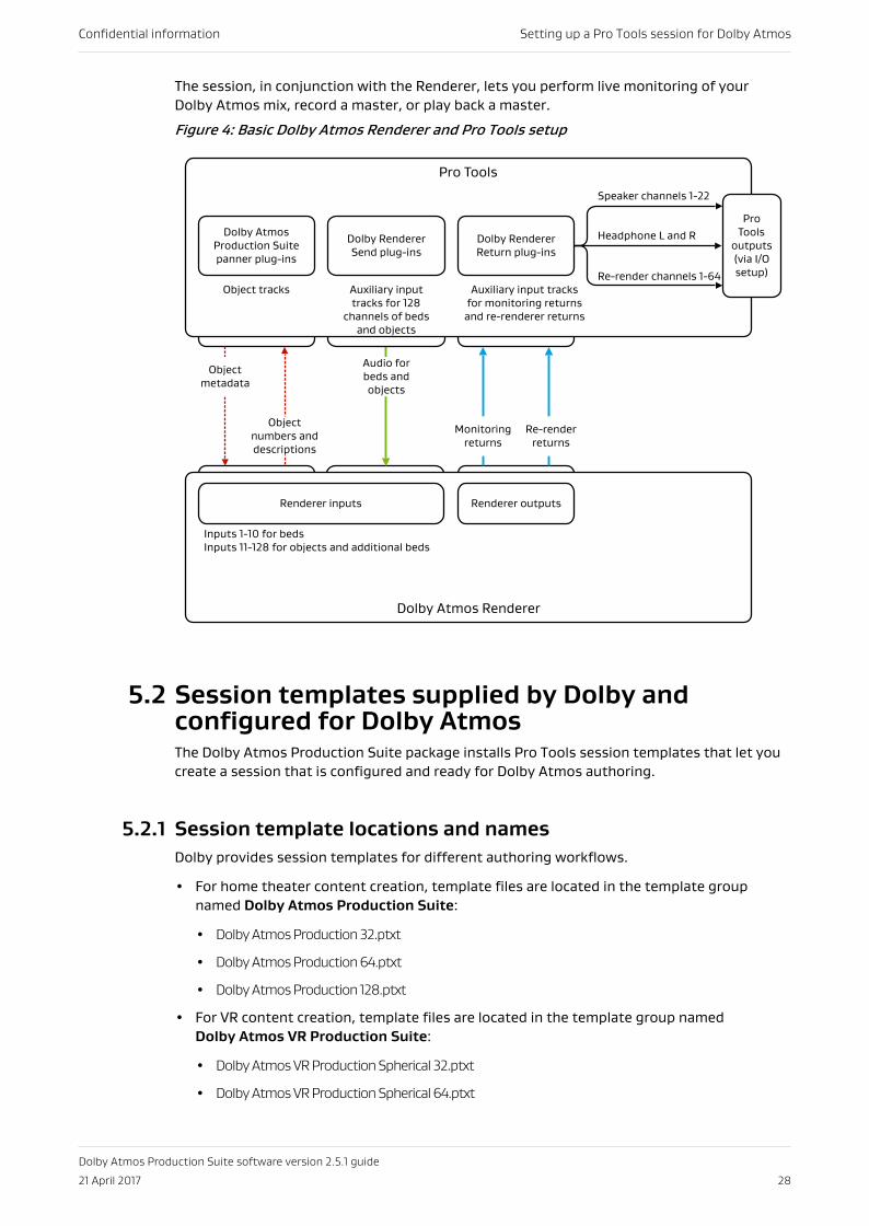
The session, in conjunction with the Renderer, lets you perform live monitoring of yourDolby Atmos mix, record a master, or play back a master.
Figure 4: Basic Dolby Atmos Renderer and Pro Tools setup
Dolby Atmos Renderer
Pro Tools
Dolby Atmos Production Suite panner plug-ins
Dolby Renderer Send plug-ins
Speaker channels 1-22
Headphone L and R
Re-render channels 1-64
Pro Tools
outputs (via I/O setup)
Renderer inputs
Object numbers and descriptions
Object metadata
Audio for beds and objects
Monitoring returns
Renderer outputs
Dolby Renderer Return plug-ins
Inputs 1-10 for bedsInputs 11-128 for objects and additional beds
Object tracks Auxiliary input tracks for 128
channels of beds and objects
Re-render returns
Auxiliary input tracks for monitoring returns
and re-renderer returns
5.2 Session templates supplied by Dolby andconfigured for Dolby AtmosThe Dolby Atmos Production Suite package installs Pro Tools session templates that let youcreate a session that is configured and ready for Dolby Atmos authoring.
5.2.1 Session template locations and namesDolby provides session templates for different authoring workflows.
• For home theater content creation, template files are located in the template groupnamed Dolby Atmos Production Suite:
• Dolby Atmos Production 32.ptxt
• Dolby Atmos Production 64.ptxt
• Dolby Atmos Production 128.ptxt
• For VR content creation, template files are located in the template group namedDolby Atmos VR Production Suite:
• Dolby Atmos VR Production Spherical 32.ptxt
• Dolby Atmos VR Production Spherical 64.ptxt
Confidential information Setting up a Pro Tools session for Dolby Atmos
Dolby Atmos Production Suite software version 2.5.1 guide
21 April 2017 28
• Dolby Atmos VR Production Spherical 128.ptxt
• Dolby Atmos VR Production XYZ 32.ptxt
• Dolby Atmos VR Production XYZ 64.ptxt
• Dolby Atmos VR Production XYZ 128.ptxt
5.2.2 Session template specificationsEach template includes tracks and plug-ins to support using the Dolby Atmos Renderer forlive monitoring of a Dolby Atmos mix, recording a master, and playing back a master.
Templates include:
• Two audio tracks for 9.1 bed material: A 7.1 multichannel track and a stereo overhead track
• Up to 118 mono audio tracks for objects, depending on the template:
• Templates with 32 in their name support 22 objects.
• Templates with 64 in their name support 54 objects.
• Templates with 128 in their name support 118 objects.
• One type of Production Suite panner plug-in inserted on each object track, depending onthe template:
• Dolby Atmos Production Suite templates use Dolby Atmos Panner plug-ins.
• Dolby Atmos VR Production templates with Spherical in their name use Dolby Atmos VRSpherical Panner plug-ins.
• Dolby Atmos VR Production templates with XYZ in their name use Dolby Atmos VR XYZPanner plug-ins.
• Dolby Renderer Send plug-ins inserted on auxiliary input tracks, configured for aDolby Atmos mix using one 9.1 bed and up to 118 mono objects (depending on thetemplate)
• Dolby Renderer Return plug-ins inserted on auxiliary input tracks, configured forreturning a stereo mix of rendered audio and 22 channels of rendered speaker audio
Note: Pro Tools session templates supplied by Dolby and configured for Dolby Atmos donot include return tracks that route re-render outputs from the Dolby Atmos Renderer.If needed, these tracks must be created and configured with Dolby Renderer Returnplug-ins.
5.3 Creating a Pro Tools session from the templatesupplied by DolbyUse a Pro Tools template supplied by Dolby to quickly create a session configured forDolby Atmos.
Procedure
1. Launch Pro Tools.
2. Locate a session template supplied by Dolby, and create a new session from the template.
You can use the Pro Tools dashboard to locate and create a session from the template:
Confidential information Setting up a Pro Tools session for Dolby Atmos
Dolby Atmos Production Suite software version 2.5.1 guide
21 April 2017 29
a) If the Pro Tools dashboard does not display on launch, choose File > Create New.
b) In the dashboard, select the Create tab.
c) Set the Type to Session.
d) Click (check) the Create From Template option.
e) Click the Template Group drop-down menu, and select one of the pre-installed Dolbytemplates.
• For home theater content creation workflows, templates are located in thetemplate group named Dolby Atmos Production Suite.
• For VR content creation workflows, templates are located in the template groupnamed Dolby Atmos VR Production Suite.
f) If the template is not selected, click on it.
g) Name the session to be created from the template.
h) Make sure the Sample Rate is set to 48 kHz.
i) Make sure the H/W Buffer Size is set to 1024 Samples.
j) Change other options if needed.
k) Click the Create button.
3. Update the session configuration as needed.
For example, you can replace some mono object tracks and Production Suite panner plug-ins with stereo tracks and stereo panner plug-ins.
4. Save the session.
5.4 Creating your own Pro Tools session forDolby AtmosYou can create your own Dolby Atmos session, instead of using a Pro Tools session templatesupplied by Dolby. To create a Pro Tools session for Dolby Atmos, create paths and tracks,add the Dolby Atmos plug-ins, configure the beds and objects, set up the send and returntracks, and set up the outputs.
Prerequisites
• Dolby Atmos Renderer and Pro Tools are open.
• Dolby Atmos Renderer is configured with input and output settings.
• Dolby Atmos operation mode in the Renderer is set correctly. For home theaterworkflows, select Home Theater. For VR workflows, select VR.
• New or existing Pro Tools session with a 48 kHz sample rate; hardware buffer size of 1,024samples (recommended).
About this taskThis task creates a Pro Tools session for recording and monitoring a master.
Some rendering tasks do not require Dolby Renderer Send or Return plug-ins and thechannels they would be inserted on:
• Playing back a master: Does not use Dolby Renderer Send plug-ins
• Recording re-renders: Does not use Dolby Renderer Send plug-ins
Confidential information Setting up a Pro Tools session for Dolby Atmos
Dolby Atmos Production Suite software version 2.5.1 guide
21 April 2017 30
• Creating re-renders offline: Does not use Dolby Renderer Return plug-ins
Procedure
1. In the Pro Tools I/O setup, update the bus page with new paths to support a Dolby Atmosmix:
a) Add a 7.1 bus path with automatically created subpaths.
b) Add an overhead stereo path with automatically created subpaths.
c) Add paths for each object (up to 118 mono objects, or a combination of mono andstereo objects totaling up to 118 object channel paths).
d) Verify that your left and right outputs are mapped to your system stereo outputs.
2. Create audio tracks for beds and objects:
a) Create one new 7.1 audio track, and name it 7.1 Bed.
b) Create one new stereo audio track, and name it OH Bed (for overheads).
c) Create up to 118 mono audio tracks, and name each track in sequential order (such asObject 1, Object 2, and so on).
You can also create a combination of mono and stereo audio tracks totaling up to 118channels, and name each track in sequential order (such as Object 1, Object 2, and so onfor mono tracks; Object 1-2 for stereo tracks).
3. Create auxiliary input tracks for sending audio and metadata to the Dolby AtmosRenderer:
a) Create one new 7.1 auxiliary input track, and name it 7.1 Bed Send.
b) Create one new stereo auxiliary input track, and name it OH Bed Send.
c) Create up to 118 mono auxiliary input tracks for the Dolby Atmos objects, and namethem accordingly, starting with the first object (for example, SND_OBJ_IN_1,SND_OBJ_IN_2, and so on).
Note: For stereo objects, create two auxiliary input tracks.
4. Configure the bed audio tracks, which provide the bed audio for your Dolby Atmos mix:
a) Set the output for the 7.1 bed track to its respective bus.
b) Set the output for the overhead bed track to its respective bus.
5. Configure the object audio tracks, which provide the object audio and metadata for yourDolby Atmos mix:
Confidential information Setting up a Pro Tools session for Dolby Atmos
Dolby Atmos Production Suite software version 2.5.1 guide
21 April 2017 31
a) Open the Mixing page of the Pro Tools Preferences window, and click (enable) thePlug-in Controls Default to Auto-Enabled option.
This eliminates the need to individually enable the plug-in parameters in each pannerplug-in after you insert them.
b) Set the output for each track to its respective bus. For example, for the track namedObject 1, set the output to bus 1.
c) Insert a Production Suite panner plug-in on each object track.
For home theater workflows, insert Dolby Atmos Panner plug-ins. For VR workflows,insert Dolby Atmos VR Spherical Panner and Dolby Atmos VR XYZ Panner plug-ins, asneeded. The plug-in supports inserting panner plug-ins across multiple tracks at once.
d) In each panner plug-in, assign the plug-in to its respective input channel number anddescription (as defined in the Renderer input screen). The plug-in supports assigningmultiple panner plug-ins across multiple tracks at once.
6. Configure the send (SND) tracks, which route audio to the Dolby Atmos Renderer:
Note: For Pro Tools HDX systems, use the DSP version of the Dolby Renderer Sendplug-in. For Pro Tools native systems, use the native version of the plug-in.
a) Set the input for each track to its respective bus path. For example, for the tracknamed 7.1 Bed Send, set the input to Path 1, and for the track named Object 1, set theinput to Bus 1.
b) For the greater-than-stereo return track, insert a Dolby Renderer Send multimonoplug-in.
c) For the stereo send track, insert a Dolby Renderer Send multimono plug-in.
d) For each mono send track, insert a Dolby Renderer Send mono plug-in.
e) In each Dolby Renderer Send plug-in, route the plug-in to its respective Renderer sendchannel.
For example, for the plug-in on the track named 7.1 Bed Send, set the plug-in to Send 1(which automatically sets the routing to Send 1 to Send 8, to cover bed channels for L, R, C,Low-Frequency Effects (LFE), Lss, Rss, Lrs, and Rrs), for the stereo plug-in on track namedOH Bed Send, set the plug-in to Send 9, and for the plug-in on the first object track, set theplug-in to Send 11.
Note: When you are finished configuring the send tracks, you can hide them in ProTools, as you will not need to see or change these tracks and their plug-ins duringDolby Atmos mixing.
7. Create and configure the return tracks that route rendered audio from the Dolby AtmosRenderer, and then out of Pro Tools outputs for monitoring:
Note: For Pro Tools HDX systems, use the DSP version of the Dolby Renderer Returnplug-in. For Pro Tools native systems, use the native version of the plug-in.
Confidential information Setting up a Pro Tools session for Dolby Atmos
Dolby Atmos Production Suite software version 2.5.1 guide
21 April 2017 32
a) Create two mono auxiliary tracks for returning a binaural mix of rendered audio fromthe Dolby Atmos Renderer, and name the tracks Headphone L and Headphone R.
b) Set the output of the headphone return tracks to route to your system stereo left andright outputs, respectively.
c) Create up to 22 mono auxiliary input tracks for returning rendered speaker audio fromthe Dolby Atmos Renderer, and name them accordingly (such as RTN_SPK_1).
d) Set the output of each speaker return track to an available Pro Tools output. Thisprovides speaker monitoring.
Note: For VR mode, or either Home Theater or VR mode with expert mode enabled,monitoring is available only when the Speaker monitoring option is set to on.
e) For each mono return track, insert a Dolby Renderer Return mono plug-in.
f) For stereo return tracks, insert a Dolby Renderer Return multimono plug-in on the firststereo return track, unlink the L and R channel in the plug-in (using the Master Linkbutton), and then copy (Option-drag) the plug-in to any other stereo return tracks.
g) For greater-than-stereo return tracks, insert Dolby Renderer Return multimono plug-ins in each greater-than-stereo multichannel track, and then unlink the channels ineach plug-in (using the Master Link button in the plug-in).
h) In each Dolby Renderer Return plug-in, route the plug-in to its respective Rendereroutput channel.
For example, for the plug-in on the track named Headphone Left, route to Headphone L,and for the plug-in on the track named RTN_SPK_1, route to Speaker Channel 1.
Note: Ensure that Dolby Renderer Return plug-ins on multichannel tracks havetheir channels unlinked in the plug-in prior to routing them. When channels arelinked, routing selections are ignored.
8. Create and configure the return tracks that route re-render outputs from the DolbyAtmos Renderer, and then out of Pro Tools outputs (for monitoring) or bussed to audiotracks (for recording):
Note: Pro Tools session templates supplied by Dolby and configured for Dolby Atmosdo not include return tracks that route re-render outputs from the Dolby AtmosRenderer. If needed, these tracks must be created and configured with DolbyRenderer Return plug-ins.
Confidential information Setting up a Pro Tools session for Dolby Atmos
Dolby Atmos Production Suite software version 2.5.1 guide
21 April 2017 33
a) Create up to 64 mono auxiliary input tracks for returning and recording re-renderaudio from the Dolby Atmos Renderer, and name them accordingly (such as RTN_RR_1).
b) Set the output of each re-render return track to an available Pro Tools output (formonitoring) or bus the audio to an available audio track (for recording).
c) For each mono return track, insert a Dolby Renderer Return mono plug-in.
d) For stereo return tracks, insert a Dolby Renderer Return multimono plug-in on the firststereo return track, unlink the L and R channel in the plug-in (using the Master Linkbutton), and then copy (Option-drag) the plug-in to any other stereo return tracks.
e) For greater-than-stereo return tracks, insert Dolby Renderer Return multimono plug-ins in each greater-than-stereo multichannel track, and then unlink the channels ineach plug-in (using the Master Link button in the plug-in).
f) In each Dolby Renderer Return plug-in, route the plug-in to its respective Rendereroutput channel. For example, for the plug-in on the track named RTN_RR_1, route to Re-render Channel 1.
Note: Ensure that Dolby Renderer Return plug-ins on multichannel tracks havetheir channels unlinked in the plug-in prior to routing them. When channels arelinked, routing selections are ignored. If you subsequently relink the channels, therouting is reset to None.
9. Save the session.
Related information
Inserting multiple panner plug-ins and automatically assigning channels on page 36
5.4.1 Considerations when inserting panner plug-ins in Pro ToolsIn Pro Tools, you can insert Production Suite panner plug-ins on mono or stereo tracks thatare identified as Dolby Atmos objects.
Note: When Pro Tools plug-ins are organized by category, the panner plug-in is locatedin the Sound Field submenu. When organized by company, it is in the DolbyLaboratories submenu.
You can insert panner plug-ins individually, or on multiple tracks simultaneously (using thePro Tools all-selected shortcut):
• When you insert panner plug-ins individually on tracks, Renderer input channel numbersare not assigned. This means that the plug-in is disabled until an input channel number isassigned to it.
• When you insert panner plug-ins using the Pro Tools all-selected shortcut, you canchoose how to autoassign input channel numbers. For example, you can choose to notautoassign input channel numbers in the new plug-ins, or to autoassign new numbersacross new and old plug-ins, or new plug-ins only.
You must assign a Renderer input channel number to a plug-in to enable it. This number isused by the Dolby Atmos Renderer to identify the object and render its metadata. Stereoplug-ins have two input channel number assignments, one for each mono subpath.
You can manually assign Renderer input channel numbers in the plug-in window, orautoassign input channel numbers when inserting plug-ins with the Pro Tools all-selectedshortcut. Inserting plug-ins across multiple tracks and autoassigning input channel numberswill save you time and simplify the process of adding panner plug-ins to your Dolby Atmossessions.
Confidential information Setting up a Pro Tools session for Dolby Atmos
Dolby Atmos Production Suite software version 2.5.1 guide
21 April 2017 34
For consistency and ease of use, you should insert all panner plug-ins in the same insertposition (for example, at the beginning or end of the inserts chain). This also makes it easierto display the knobs on a control surface.
Note: Typically, you should align the input channel number assignment with your trackname and the number used to name the channel path or subpath. This will help create alogical and consistent numbering and naming scheme.
For example, insert the first plug-in on a track named Object 1 (for a mono track) or on atrack named Object 1–2 (for a stereo track).
For home theater workflows, insert Dolby Atmos Panner plug-ins. For VR workflows, insertDolby Atmos VR Spherical Panner and Dolby Atmos VR XYZ Panner plug-ins, as needed.
5.5 Channel assignments for Dolby Atmos plug-insChannel assignments for Dolby Atmos plug-ins are based on the plug-in type and routingpath.
Dolby Atmos Production Suite panner plug-insThese plug-ins route metadata to the Renderer input (via the Render Send plug-in). Theavailable object numbers and the descriptions for objects are based on the objects anddescriptions configured in the Renderer input screen. None disables the plug-in. When aplug-in is inserted on a single track, or inserted with multiple plug-ins and no automaticassignments, the channel assignment defaults to None.
Dolby Renderer Send plug-inThis plug-in routes audio to the Renderer input. The available input channels, input type(beds or objects), and descriptions for each bed and object are based on the input typesand labeling configured in the Renderer input screen. The list of available channelsincludes inputs 1 - 118. In the user interface (UI), each available bed and object channel ispreceded by Bed Channel and Object Channel, respectively.
Dolby Renderer Return plug-inThis plug-in routes rendered audio from the Renderer output back to Pro Tools. The listof available channels includes speaker channel 1 - 22, headphone L and headphone R, andre-render channel 1 - 64.
Table 3: Channel order for input channelsPro Tools track output paths (I/O setup buschannels)
Renderer Send channel inputs
L L
C R
R C
Lss LFE
Rss Lss
Lsr Rss
Rsr Lrs
LFE Rrs
L (left overhead) Lts (left overhead)
R (right overhead) Rts (right overhead)
C, or L, R (objects 1 to 118) C, or L, R (objects 1 to 118)
Confidential information Setting up a Pro Tools session for Dolby Atmos
Dolby Atmos Production Suite software version 2.5.1 guide
21 April 2017 35
5.6 Manually assigning an input channel numberManually assign a channel to enable a single plug-in that does not have an assignment, or tochange an existing channel assignment to another assignment.
Procedure
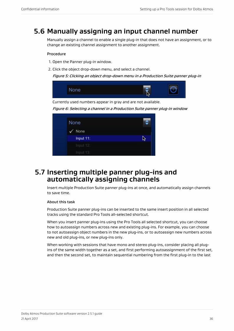
1. Open the Panner plug-in window.
2. Click the object drop-down menu, and select a channel.
Figure 5: Clicking an object drop-down menu in a Production Suite panner plug-in
Currently used numbers appear in gray and are not available.
Figure 6: Selecting a channel in a Production Suite panner plug-in window
5.7 Inserting multiple panner plug-ins andautomatically assigning channelsInsert multiple Production Suite panner plug-ins at once, and automatically assign channelsto save time.
About this task
Production Suite panner plug-ins can be inserted to the same insert position in all selectedtracks using the standard Pro Tools all-selected shortcut.
When you insert panner plug-ins using the Pro Tools all selected shortcut, you can choosehow to autoassign numbers across new and existing plug-ins. For example, you can chooseto not autoassign object numbers in the new plug-ins, or to autoassign new numbers acrossnew and old plug-ins, or new plug-ins only.
When working with sessions that have mono and stereo plug-ins, consider placing all plug-ins of the same width together as a set, and first performing autoassignment of the first set,and then the second set, to maintain sequential numbering from the first plug-in to the last
Confidential information Setting up a Pro Tools session for Dolby Atmos
Dolby Atmos Production Suite software version 2.5.1 guide
21 April 2017 36
Procedure
1. Choose (highlight) one or more track names.
2. Option+Shift-click a plug-in selector, and while still holding down the keys, select theplug-in.
3. In the dialog, choose an autoassign option.
5.7.1 Autoassign optionsWhen inserting Dolby Atmos plug-ins with the Pro Tools all-selected shortcut,autoassignment options are provided based on the type of plug-in.
The autoassignment options include:
None (All Dolby Atmos plug-ins)
Choose this option to autoassign no channels to plug-ins. New plug-ins are not assignedchannels. Existing plug-ins are unaffected and retain their channel assignments.
Overwrite existing (Production Suite panner plug-in only)Choose this option to autoassign channels to all plug-ins. All panner plug-ins areassigned (or reassigned) the next available input channel number for a mono object (orthe next two available numbers for a stereo object). Assignments are made in tracksequential order (left to right, or top to bottom). Existing plug-ins are affected,depending on where they are located in the session.
Preserve (Production Suite panner plug-in only)Choose this option to autoassign channels to new plug-ins only. Each new panner plug-inis autoassigned the next available input channel number for a mono object (or the nexttwo available numbers for a stereo object). Assignments are made in track sequentialorder (left to right, or top to bottom). Existing plug-ins are unaffected and retain theirobject numbers.
Next Available (Dolby Renderer Send and Return plug-ins)
Choose this option to skip the first sequence of available channels and start theautoassign with the next available channel. Assignments are made in track sequentialorder (left to right, or top to bottom). Existing plug-ins are unaffected and retain theirchannel assignments.
First Available (Dolby Renderer Send and Return plug-ins)Choose this option to autoassign channels starting with the first available channel.Assignments are made in track sequential order (left to right, or top to bottom). Existingplug-ins are unaffected and retain their channel assignments.
Confidential information Setting up a Pro Tools session for Dolby Atmos
Dolby Atmos Production Suite software version 2.5.1 guide
21 April 2017 37
6 Positioning objects in aDolby Atmos mixPosition objects in a Dolby Atmos mix by writing panner automation parameters to objecttracks in Pro Tools.
• Automating panner controls• Panner automatable controls• Changing object location• Positioning tasks specific to Home Theater workflows• Positioning tasks specific to VR workflows
6.1 Automating panner controlsYou can automate many of the Production Suite panner plug-in controls in Pro Tools. Therecorded (written) automation for these controls defines the metadata that is sent to theRenderer for rendering a Dolby Atmos mix (or for re-rendering to a surround format).
Procedure
1. Enable plug-in automation for the session by performing these steps in Pro Tools:
a) Choose Window > Automation.
b) Click (enable) the Enable Plug-in Automation option in the Write Enable section ofthe Automation window.
2. Enable plug-in automation parameters in each panner plug-in by performing these steps:
Note: Skip this step if you enabled Plug-in Controls Default to Auto-Enabled priorto adding Production Suite panner plug-ins to the session.
a) Open a panner plug-in.
b) In the panner plug-in window, Command+Option+Control the automation button atthe top of the plug-in window to enable all automatable plug-in parameters.
Alternatively, you can click on the automation plug-in window, and then addparameters individually.
3. Prepare each object track for recording panner automation by performing these steps:
a) In each object track, set the automation mode to Write (or one of the otherautomation record modes).
To set all object tracks at once, select each object track, and then use Shift+Optionwhen setting the automation mode.
b) Optional: In the edit window, display automation lanes for each panner parameter inan object track by clicking show/hide lane, and then adding each parameter lane.
To display lanes for all object tracks at once, select each object track, and then useShift+Option when clicking show/hide lane and adding lanes.
4. Start playback, and automate panner controls as desired.
Confidential information Positioning objects in a Dolby Atmos mix
Dolby Atmos Production Suite software version 2.5.1 guide
21 April 2017 38
You can change panner parameters using any of the available methods to control thepanner (such as using a joystick).
5. When done recording automation, stop playback.
6.2 Panner automatable controlsEach Production Suite panner supports automation of its primary controls, including thosefor positioning an object. Configuration settings are not automatable.
Most standard Pro Tools plug-in and automation controls are available for the plug-in.
Refer to Pro Tools documentation for additional information on working with plug-ins,including:
• Inserting plug-ins on tracks
• Plug-in window controls
• Automating plug-ins
6.2.1 Dolby Atmos Panner automatable controlsThe Dolby Atmos Panner plug-in supports automation of its primary controls, includingthose for positioning an object.
Bypass (master bypass)Bypass status for plug-in metadata (on or off). When set to on, audio from the objecttrack continues to output from the Dolby Atmos Renderer.
Pan XPan location in the x (left/right) dimension (-100 to 100).
Pan YPan location in the y (front/back) dimension (-100 to 100).
Pan ZPan location in the z (top/bottom) dimension (0 to 100).
Size0 to 100.
ElevationElevation status (on or off).
Elevation snapElevation Snap mode states (ceiling elevation, wedge elevation, sphere elevation, or off).
SnapSpeaker Snap mode status (on or off).
ZonesActive speaker zones (back only, front only, three, five back, five, and seven).
6.2.2 Dolby Atmos VR Spherical Panner automatize controlsThe Dolby Atmos VR Spherical Panner supports automation of its primary controls, includingthose for positioning an object.
Confidential information Positioning objects in a Dolby Atmos mix
Dolby Atmos Production Suite software version 2.5.1 guide
21 April 2017 39
Bypass (master bypass)Bypass status for plug-in metadata (on or off). When set to on, audio from the objecttrack continues to output from the Dolby Atmos Renderer.
Pan azimuthPosition of the object around around a horizontal plane in the soundfield (–180 to 180).
Pan inclinationAngle between the object and horizontal plan (-90 to 90).
Pan distancePosition of the object in respect to the listener (0 to 100).
Head trackingObject head tracking status (on or off). On is scene relative. Off is head relative.
Binaural distance modelDistance models (binaural far, binaural near, or flat stereo).
6.2.3 Dolby Atmos VR XYZ Panner automatable controlsThe Dolby Atmos VR XYZ Panner supports automation of its primary controls, includingthose for positioning an object.
Bypass (master bypass)Bypass status for plug-in metadata (on or off). When set to on, audio from the objecttrack continues to output from the Dolby Atmos Renderer.
Pan XPan location in the x (left/right) dimension (‑100 to 100).
Pan YPan location in the y (front/back) dimension (‑100 to 100).
Pan ZPan location in the z (top/bottom) dimension (‑100 to 100).
Head tracking (binaural controls enabled)Object head tracking status (on or off). On is scene relative. Off is head relative.
Binaural distance model (binaural controls enabled)Distance models (binaural far, binaural near, or flat stereo).
6.3 Changing object locationSliders in the panner plug-in let you adjust the location of the object.
About this task
The available slider controls are dependent on the plug-ins used for your workflow:
• For home theater workflows (which use the Dolby Atmos Panner) or VR workflows usingthe Dolby Atmos VR XYZ Panner, the plug-ins include X, Y, and Z sliders. These sliders letyou adjust the location of the object in the virtual room, through all three dimensions: x(left/right), y (front/back), and z (top/bottom).
Dolby Atmos Panner additional information: When Elevation mode is off (elevation buttonnot highlighted), you can adjust x and y coordinates, but you cannot adjust the zcoordinate. When Elevation mode is on, you can also adjust the z dimension. In Ceilingand Wedge Elevation Snap modes, the z coordinate is generated from the y coordinate
Confidential information Positioning objects in a Dolby Atmos mix
Dolby Atmos Production Suite software version 2.5.1 guide
21 April 2017 40
only, and changes as the y coordinate is changed. In Sphere Elevation Snap mode, the zcoordinate is generated from x and y coordinates, and changes as they are changed.
• For VR workflows using the Dolby Atmos VR Spherical Panner, the plug-in includesazimuth (θ), inclination (φ), and distance (ρ) spherical sliders. These sliders let you adjustthe location of the object in a simulated video projection, through space.
You can use a mouse, joystick, control surface, enabled automation, or keyboard entry toadjust the location. As sliders or position display values are adjusted, the pan location cursorin the plug-in window moves accordingly. Inversely, the sliders and position display valuesupdate when the cursor is adjusted.
You can place or pan an object from any location in the panner window to any other location.
Respective position displays provide the value (or coordinates) of the current objectposition, whether moving the pan location with a mouse, joystick, control surface, enabledautomation, or keyboard entry.
Note: If the sliders and their position displays are not visible at the bottom of the plug-in window, click the Done button in the Configuration Options section to close theoptions and reveal the sliders and their values.
Procedure
Perform one of these steps:
• Click the slider button, and drag to the desired coordinate.
• Click in the slider range to jump to a new coordinate.
• Type a valid value in a slider position display, and press Enter.
6.4 Positioning tasks specific to Home TheaterworkflowsWhen using the Dolby Atmos Panner for home theater authoring, you can set Elevationmodes and change object size in the panner plug-in window.
6.4.1 Using Elevation modeElevation mode lets you manually adjust the z (top/bottom) dimension in the Dolby AtmosPanner virtual room.
About this task
When on (elevation button highlighted), two overhead zones are made active in the room(and are displayed as two blue squares left and right of the center of the room). Elevationmode is on by default.
Elevation mode forms a flat ceiling across the virtual room. The elevation z coordinate is notlinked to x and y coordinates, and is adjusted independently. You can adjust the elevationacross the room with a joystick, control surface, mouse, or enabled automation.
Procedure
1. Turn on Elevation mode by performing one of these steps:
• Click (highlight) the elevation button.
• Use a control surface.
Confidential information Positioning objects in a Dolby Atmos mix
Dolby Atmos Production Suite software version 2.5.1 guide
21 April 2017 41
• Use a joystick.
2. Adjust elevation (the Z setting) using any of these:
• Control surface
• Joystick
• Mouse (with the Z slider)
You can automate Elevation mode on and off in Pro Tools by using the Elevation modeautomation playlist.
6.4.2 Elevation snap modesElevation Snap mode refers to the automation playlist that supports modes that change theshape of the ceiling in the room, and in turn, how z values for elevation drop as they moveaway from the middle of the room.
• Ceiling elevation gives the room a flat ceiling in the back 80% of the room and a curvingceiling from the front 20% of the room to the screen.
• Sphere elevation gives the room a domed ceiling.
• Wedge elevation gives the room a peaked ceiling.
You can automate Elevation Snap modes in Pro Tools by using the Elevation Snap modeautomation playlist. Elevation Snap mode has four states: ceiling elevation, wedge elevation,sphere elevation, and off.
6.4.3 Using ceiling elevationCeiling elevation links the z elevation to the y coordinate to form a flat ceiling inside thePanner virtual room that curves from the front 20% of the room to the screen.
About this task
The elevation is constant in the back 80% of the room. Elevation drops uniformly as objectsare moved away from the front 20% of the room to the screen. Left or right movements onthe x-axis do not change the object elevation.
Procedure
1. Turn on ceiling elevation by performing one of these steps:
• Click the elevation snap selector, and select (highlight) the ceiling elevation icon.
• Use a control surface.
2. Adjust elevation by moving the y coordinates with any of these:
• Joystick
• Control surface
• Mouse (on the pan location cursor or Y slider)
You can automate ceiling elevation on and off in Pro Tools by using the Elevation Snapmode automation playlist.
6.4.4 Using sphere elevationSphere elevation links the z elevation to the x and y coordinates to form a hemispheric domeinside the Panner virtual room.
Confidential information Positioning objects in a Dolby Atmos mix
Dolby Atmos Production Suite software version 2.5.1 guide
21 April 2017 42
About this task
The highest point of the dome is the exact center of the room. Elevation decreases uniformlyas you move away from the center in any direction. Elevation drops to the bottom at the fourpoints where the hemisphere meets the virtual walls.
Procedure
1. Turn on sphere elevation by performing one of these steps:
• Click the elevation snap selector, and select (highlight) the sphere elevation icon.
• Use a control surface.
• Use a joystick.
2. Adjust elevation by moving the x and y coordinates with any of these:
• Mouse (on the pan location cursor or X and Y sliders)
• Control surface
• Joystick
You can automate sphere elevation on and off in Pro Tools by using the Elevation Snapmode automation playlist.
6.4.5 Using wedge elevationWedge elevation links the z elevation to the y coordinate to form a peaked ceiling inside theDolby Atmos Panner virtual room.
About this task
The highest elevation is a line running left and right at the center of the room. Elevationdrops uniformly as objects are moved away from that center line on the y-axis toward eitherthe front or back of the room. Left or right movements on the x-axis do not change theobject elevation.
Procedure
1. Turn on wedge elevation by performing one of these steps:
• Click the elevation snap selector, and select (highlight) the wedge elevation icon.
• Use a control surface.
• Use a joystick.
2. Adjust elevation by moving the y coordinates with any of these:
• Mouse (on the pan location cursor or Y slider)
• Control surface
• Joystick
You can automate wedge elevation on and off in Pro Tools by using the Elevation Snapmode automation playlist.
6.4.6 Using Speaker Snap modeSpeaker Snap mode moves object audio to the active speaker nearest its establishedlocation during playback.
Confidential information Positioning objects in a Dolby Atmos mix
Dolby Atmos Production Suite software version 2.5.1 guide
21 April 2017 43
About this task
At the Renderer, this ensures that 100% of the audio signal is routed to the single speakerthat is nearest to the current spatial placement. The location of the speaker that the objectsnaps to is based on the current room configuration (defined by the .dac file, located on theRenderer), and can vary from one room to another. Speakers in inactive zones are ignored inSpeaker Snap mode.
Speaker Snap mode does not move the pan location cursor in the virtual room.
Speaker Snap mode is useful for eliminating phantom panning. For example, in the DolbyAtmos Panner default mode (Speaker Snap mode off), the algorithm might spread the audioof one object across two or more speakers. Speaker Snap mode prevents this by snapping allof the audio to the single speaker nearest the indicated position of the object in the Pannervirtual room.
Note: For a visual representation of which speaker the audio snaps to, look at the roomconfiguration in the Dolby Atmos Monitor application.
When Speaker Snap mode is on, object size is disabled.
• Click (highlight) the speaker snap button.
• Use a control surface.
• Use a joystick.
You can automate Speaker Snap mode on and off in Pro Tools by using the snapautomation playlist.
6.4.7 Managing speaker zonesZones in the Dolby Atmos Panner plug-in define which speaker or speaker zones (excludingoverheads) are active for the object, as the Renderer interprets the object metadata.
About this task
Zones are also used when the Renderer re-renders the Dolby Atmos mix to a surroundformat (such as 7.1 or 5.1 channels). Zones can be useful to isolate (or dedicate) an object to aspecific speaker or group of speakers.
Inactive zones are effectively muted for live monitoring or master recording. Additionally,speakers in inactive zones are ignored in Speaker Snap mode.
Zones are displayed in the virtual room as blue squares in their relative position. Zones onthe room outline represent the L, C, R, Lss, Rss, Lsr, and Rsr speakers or speaker zones.Zones are active (teal) or inactive (gray), based on the setting of the zones button.
Zones work in conjunction with Elevation mode and Elevation Snap mode, which activate theoverheads for use while panning.
Provided zones include:
Back onlyEnables Lss, Rss, Lsr, and Rsr zones
Front onlyEnables L, C, and R zones
ThreeEnables C, Lsr, and Rsr zones
Five B (back)Enables L, C, R, Lsr, and Rsr zones
Confidential information Positioning objects in a Dolby Atmos mix
Dolby Atmos Production Suite software version 2.5.1 guide
21 April 2017 44
FiveEnables L, C, R, Lss, and Rss zones
SevenEnables L, C, R, Lss, Rss, Lsr, and Rsr zones
Procedure
Change the current zone in the panner by performing one of these steps:
• Click the zones button in the panner, and select a zone.
• Use a control surface.
You can automate zones in Pro Tools by using the zones automation playlist.
6.4.8 Changing object sizeThe object Size slider lets you spread audio for an object across the room, based on thecurrent object position and active speakers in the room.
About this task
You can use a joystick, control surface, mouse, enabled automation, or keyboard to adjustthe size (or spread). The object size outline, which surrounds the object cursor in the virtualroom, shows the current spread for an object. The object size has a range of 0 to 100.
Note: If the Size slider and value display are not visible at the bottom of the plug-inwindow, click the Done button in the Configuration Options section to close theoptions and reveal the slider and its value.
• Click the slider button, and drag to the desired coordinate.
• Click in the slider range to jump to a new coordinate.
• Type a valid value in the slider value display, and press Enter.
6.4.9 Z coordinate and Dolby Atmos Panner controlsWhen using the Dolby Atmos Panner, the Z coordinate and how it renders can be affected byother controls.
• When changing object size, the Z slider position, its display value, and the z automationplaylist always match.
• Z items always represent the overhead level that is displayed in both the plug-in UI andthe Monitor application. However, there are situations where the rendered audio outputmay not match the z position being displayed. For example, if you disable Elevation modeafter writing z automation, audio will play back rendered without overheads, but the plug-in UI will continue to display the z automation.
• There are also situations where the z automation UI and rendered audio output do notupdate during a write automation pass as expected. If you enable an Elevation Snap modeduring a write automation pass, the z automation and elevation amount will not updateuntil new automation data for the corresponding slider is written. For example, when youenable Sphere Elevation Snap mode, updates occur after new x or y automation data iswritten.
Confidential information Positioning objects in a Dolby Atmos mix
Dolby Atmos Production Suite software version 2.5.1 guide
21 April 2017 45
Note: After authoring a Panner plug-in with Elevation mode or an Elevation Snap modeon, you can edit the z automation data that was recorded by using a pencil tool in the zautomation playlist. The elevation defined by the new automation will be applied to therendered object audio in the subsequent playback as long as Elevation mode is enabled.
6.5 Positioning tasks specific to VR workflowsWhen binaural controls are enabled, you can set the binaural distance model and head-tracking behavior in a Dolby Atmos VR panner plug-in window.
6.5.1 Setting how panning volume models the placement of objectsIn the panner plug-in window, you can set how the panning volume models the placement ofobjects.
About this taskThe panner provides two Binaural Distance Model buttons to set the modeling.
You can automate binaural distance modeling in Pro Tools by using the binaural distancemodel automation playlist.
• Change the current binaural distance model setting in a Dolby Atmos VR panner byperforming one of these steps:
• Click (enable) the Near Binaural Distance Model button to make the panning volumemodel the placement of objects in the vicinity of the listener’s head.
• Click (enable) the Far Binaural Distance Model button to make the panning volumemodel the placement of objects in a larger space.
• Click (disable) both the Near Binaural Distance Model button and the Far BinauralDistance Model button to disable binaural rendering for the object and enable a flatstereo mode. In this mode, the object can be positioned in stereo only (via the Xslider).
6.5.2 Setting how sound tracks to head movementsIn the panner plug-in window, you can set whether sound follows the user when they turntheir head.
About this task
The panner provides a single Head Tracking button, which is available when one of theBinaural Distance Model buttons is enabled.
You can automate head tracking in Pro Tools by using the head-tracking automation playlist.
Procedure
1. Ensure that one of the Binaural Distance Mode buttons is enabled.
2. Perform one of these steps:
• For scene-relative rendering, enable the Head Tracking button. In this mode, theobject position is independent of the user and head orientation affects the sound. Thismeans that when the user turns his or her head, the sound source arrives from adifferent direction relative to the user's head orientation.
Confidential information Positioning objects in a Dolby Atmos mix
Dolby Atmos Production Suite software version 2.5.1 guide
21 April 2017 46
• For head-relative rendering, disable the Head Tracking button. In this mode, theobject follows the user and head orientation does not affect the sound. This meansthat when the user turns his or her head, the sound source arrives from the samedirection relative to the user's head orientation.
Confidential information Positioning objects in a Dolby Atmos mix
Dolby Atmos Production Suite software version 2.5.1 guide
21 April 2017 47
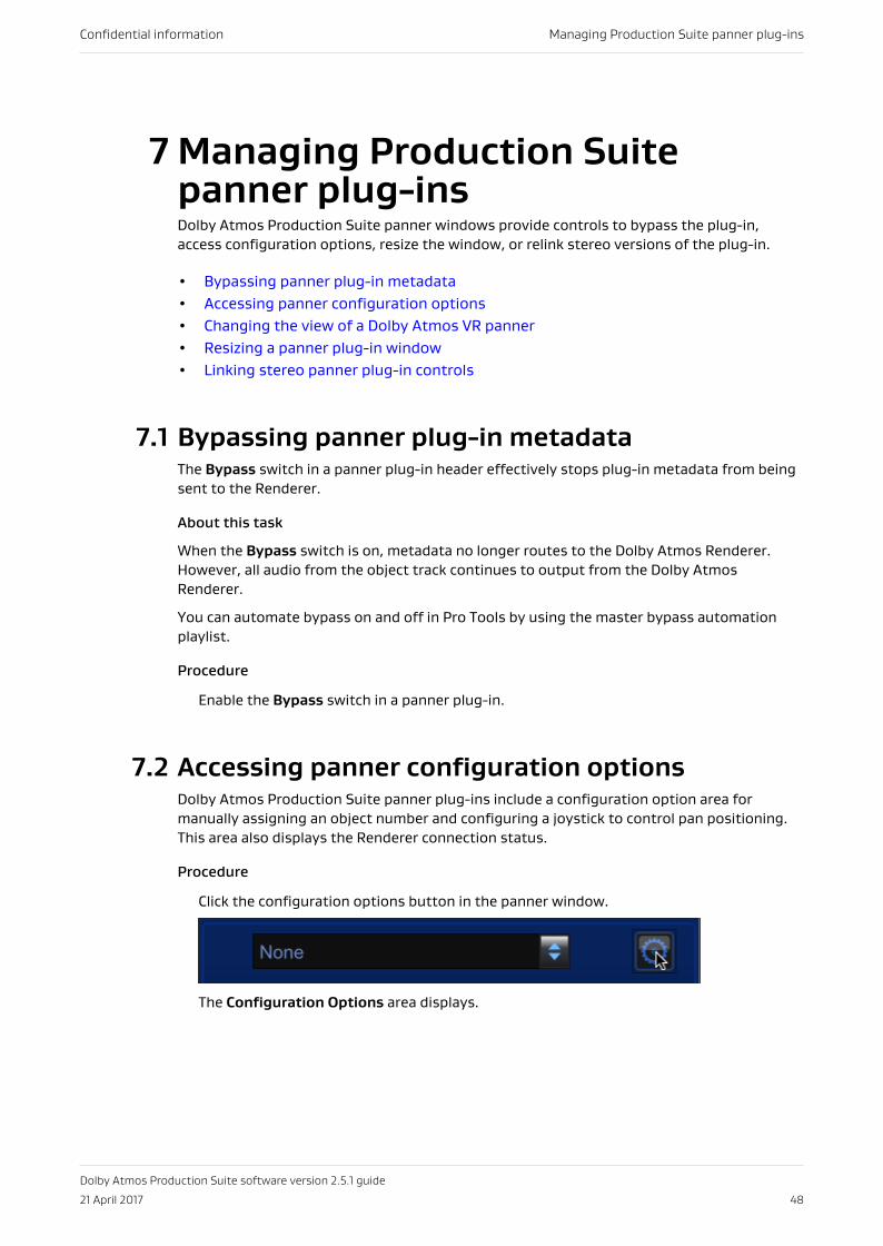
7 Managing Production Suitepanner plug-insDolby Atmos Production Suite panner windows provide controls to bypass the plug-in,access configuration options, resize the window, or relink stereo versions of the plug-in.
• Bypassing panner plug-in metadata• Accessing panner configuration options• Changing the view of a Dolby Atmos VR panner• Resizing a panner plug-in window• Linking stereo panner plug-in controls
7.1 Bypassing panner plug-in metadataThe Bypass switch in a panner plug-in header effectively stops plug-in metadata from beingsent to the Renderer.
About this task
When the Bypass switch is on, metadata no longer routes to the Dolby Atmos Renderer.However, all audio from the object track continues to output from the Dolby AtmosRenderer.
You can automate bypass on and off in Pro Tools by using the master bypass automationplaylist.
Procedure
Enable the Bypass switch in a panner plug-in.
7.2 Accessing panner configuration optionsDolby Atmos Production Suite panner plug-ins include a configuration option area formanually assigning an object number and configuring a joystick to control pan positioning.This area also displays the Renderer connection status.
Procedure
Click the configuration options button in the panner window.
The Configuration Options area displays.
Confidential information Managing Production Suite panner plug-ins
Dolby Atmos Production Suite software version 2.5.1 guide
21 April 2017 48
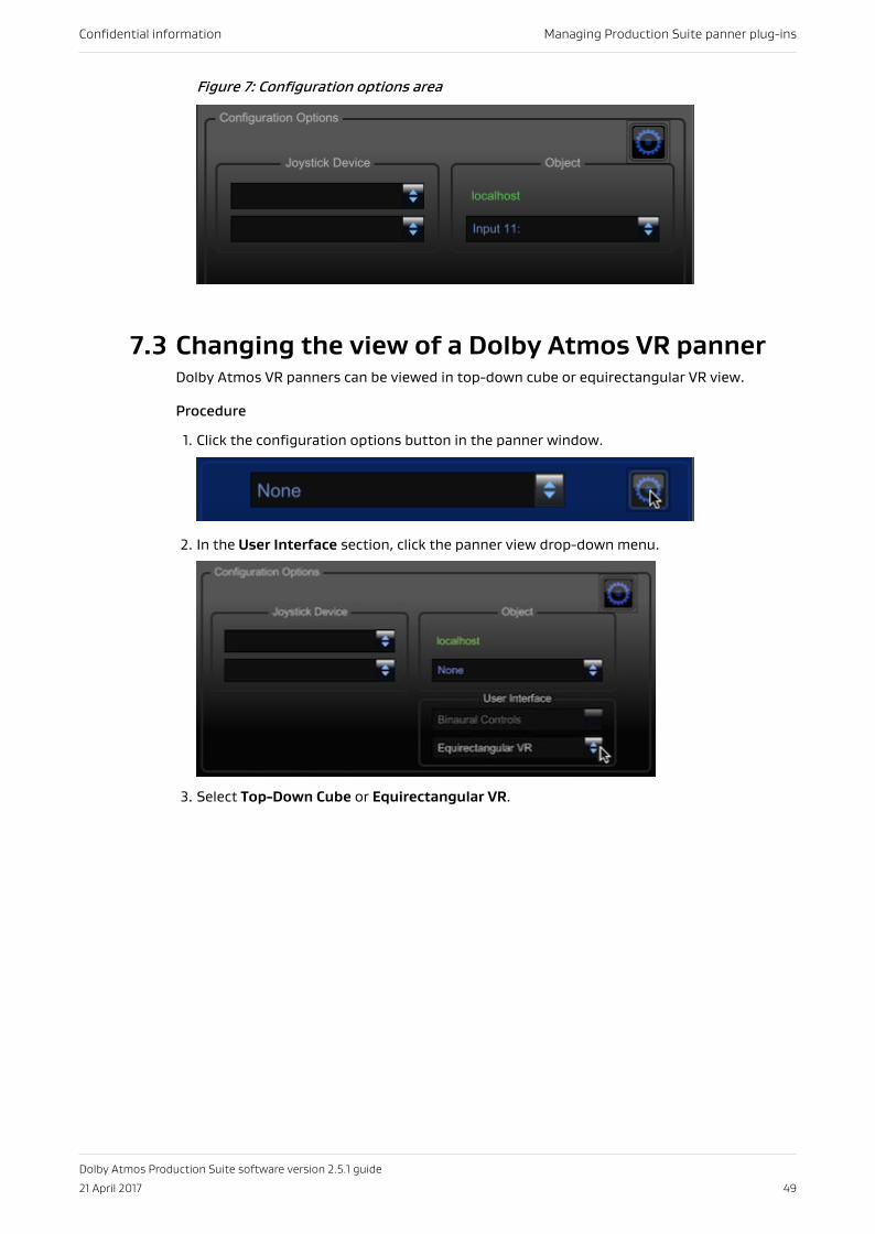
Figure 7: Configuration options area
7.3 Changing the view of a Dolby Atmos VR pannerDolby Atmos VR panners can be viewed in top-down cube or equirectangular VR view.
Procedure
1. Click the configuration options button in the panner window.
2. In the User Interface section, click the panner view drop-down menu.
3. Select Top-Down Cube or Equirectangular VR.
Confidential information Managing Production Suite panner plug-ins
Dolby Atmos Production Suite software version 2.5.1 guide
21 April 2017 49
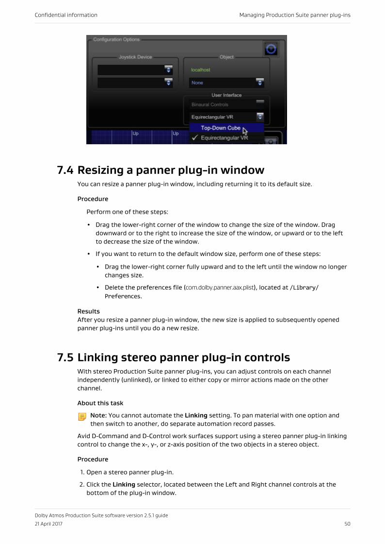
7.4 Resizing a panner plug-in windowYou can resize a panner plug-in window, including returning it to its default size.
Procedure
Perform one of these steps:
• Drag the lower-right corner of the window to change the size of the window. Dragdownward or to the right to increase the size of the window, or upward or to the leftto decrease the size of the window.
• If you want to return to the default window size, perform one of these steps:
• Drag the lower-right corner fully upward and to the left until the window no longerchanges size.
• Delete the preferences file (com.dolby.panner.aax.plist), located at /Library/Preferences.
ResultsAfter you resize a panner plug-in window, the new size is applied to subsequently openedpanner plug-ins until you do a new resize.
7.5 Linking stereo panner plug-in controlsWith stereo Production Suite panner plug-ins, you can adjust controls on each channelindependently (unlinked), or linked to either copy or mirror actions made on the otherchannel.
About this task
Note: You cannot automate the Linking setting. To pan material with one option andthen switch to another, do separate automation record passes.
Avid D-Command and D-Control work surfaces support using a stereo panner plug-in linkingcontrol to change the x-, y-, or z-axis position of the two objects in a stereo object.
Procedure
1. Open a stereo panner plug-in.
2. Click the Linking selector, located between the Left and Right channel controls at thebottom of the plug-in window.
Confidential information Managing Production Suite panner plug-ins
Dolby Atmos Production Suite software version 2.5.1 guide
21 April 2017 50
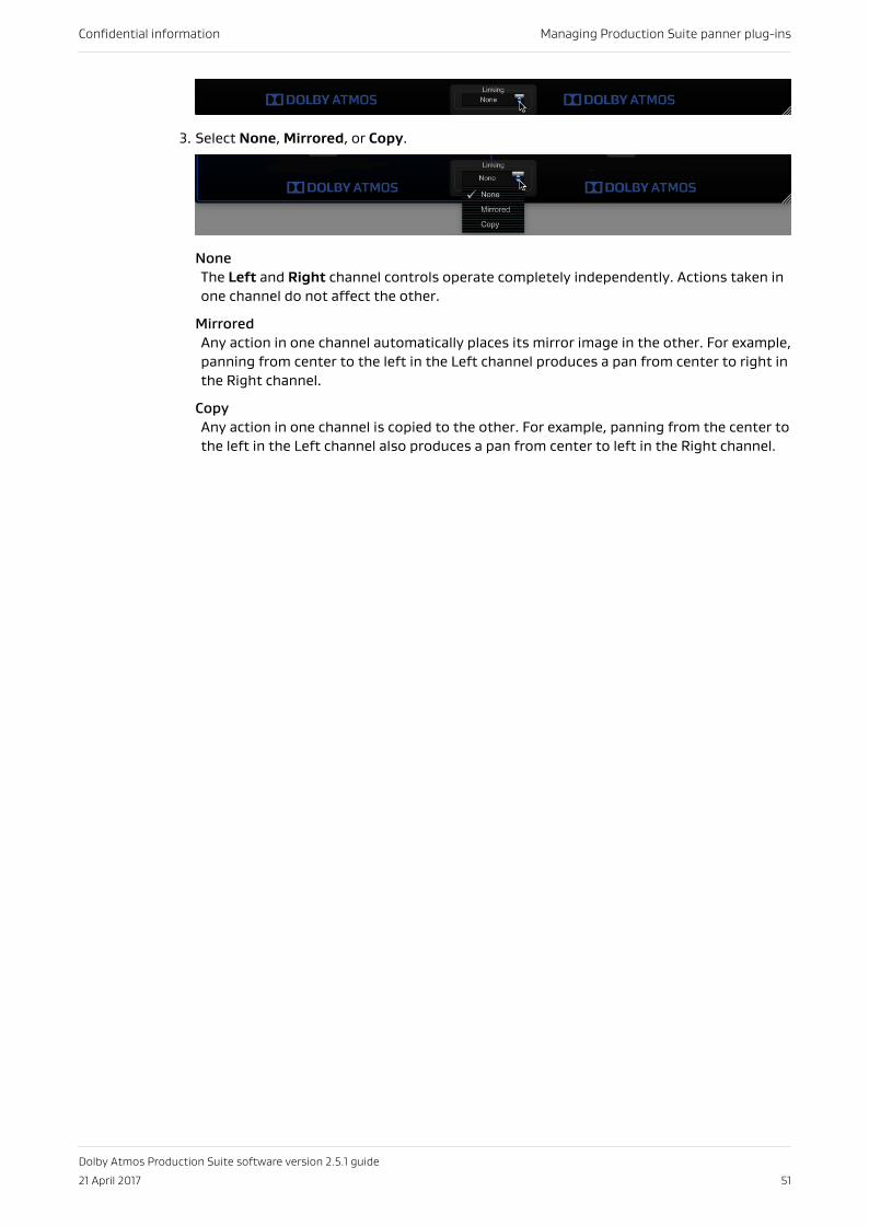
3. Select None, Mirrored, or Copy.
NoneThe Left and Right channel controls operate completely independently. Actions taken inone channel do not affect the other.
MirroredAny action in one channel automatically places its mirror image in the other. For example,panning from center to the left in the Left channel produces a pan from center to right inthe Right channel.
CopyAny action in one channel is copied to the other. For example, panning from the center tothe left in the Left channel also produces a pan from center to left in the Right channel.
Confidential information Managing Production Suite panner plug-ins
Dolby Atmos Production Suite software version 2.5.1 guide
21 April 2017 51
8 Controlling Production Suitepanner plug-ins with differenthardwareYou can control a Production Suite panner using different hardware.
• Using a mouse to position an object• Using a keyboard to position an object• Panning with a supported JLCooper controller• Control surface and mixing console support• Generic MIDI support
8.1 Using a mouse to position an objectYou can use a mouse to position the object (pan location cursor) precisely.
• Click and drag the pan location cursor, which represents the object.
• Click and hold on another location in the room to move the object to that location.
• In a slider, click the slider button and drag to the desired coordinate.
• In a slider, click in the slider range to jump to a new coordinate.
8.2 Using a keyboard to position an objectYou can use a keyboard to position an object (pan location cursor) precisely.
• Type a valid value in a slider position display, and press Enter.
8.3 Panning with a supported JLCooper controllerYou can control a Dolby Atmos Production Suite panner plug-in with any supported JLCoopercontroller. These include the JLCooper Axos surround panner, the JLCooper Eclipse PXsurround panning joystick controller, and the JLCooper MCS-Panner.
About this task
When the joystick has been prepared, you can use it to grab the object (pan location cursor)and position it anywhere in the panner virtual room.
Procedure
1. Open the plug-in window so that it is in focus.
2. Perform one of these steps:
• For a controller with a button on the top of the joystick, press and hold the button,and then move the joystick.
• For the JLCooper Axos panner, move the joystick. You can also use the joystickswitches and knobs to determine other panner behaviors.
Confidential information Controlling Production Suite panner plug-ins with different hardware
Dolby Atmos Production Suite software version 2.5.1 guide
21 April 2017 52
The switch and knob behavior for each Production Suite panner plug-in and supportedJLCooper panner is different.
8.3.1 Dolby Atmos Panner and JLCooper joystick switch and knobreferenceYou can use JLCooper joystick switches and knobs to determine different Dolby AtmosPanner behaviors. The switch and knob behavior for each supported JLCooper panner isdifferent.
JLCooper Axos switch and knob reference for the Dolby Atmos Panner
• Prev Track: Toggle Elevation and Elevation Snap modes on and off.
• Target Up: Set Wedge Elevation mode so that the mode enables when S1 is on.
• Target Down: Set Sphere Elevation mode so that the mode enables when S1 is on.
• Next Track: Set Ceiling Elevation mode so that the mode enables when S1 is on.
• Right Pan: Toggle Speaker Snap mode.
• Front Pos and LFE: Modify elevation in Elevation mode. Turning to the right elevates theobject in the audio field; turning to the left lowers the object in the audio field.
• F/R Pos: Modify size. Turning to the right decreases the size; turning to the left increasesthe size.
JLCooper Eclipse PX switch and knob reference for the Dolby Atmos Panner
• S1: Toggle Elevation and Elevation Snap modes on and off.
• S2: Set Elevation mode so that the mode enables when S1 is on.
• S3: Set Wedge Elevation mode so that the mode enables when S1 is on.
• S4: Set Sphere Elevation mode so that the mode enables when S1 is on.
• S5: Set Ceiling Elevation mode so that the mode enables when S1 is on.
• S6: Toggle Speaker Snap mode.
• E1 and E3: Modify elevation in Elevation mode. Turning to the right elevates the object inthe audio field; turning to the left lowers the object in the audio field.
• E2: Modify size. Turning to the right decreases the size; turning to the left increases thesize.
JLCooper MCS-Panner joystick switch and knob reference for the Dolby Atmos Panner
• S1: Toggle Elevation and Elevation Snap modes on and off.
• S2: Set Elevation mode so that the mode enables when S1 is on.
• S3: Set Wedge Elevation mode so that the mode enables when S1 is on.
• S4: Set Sphere Elevation mode so that the mode enables when S1 is on.
• S5: Set Ceiling Elevation mode so that the mode enables when S1 is on.
• S6: Toggle Speaker Snap mode.
• E1 and E2: Modify elevation. Turning to the right elevates the object in the audio field;turning to the left lowers the object in the audio field.
• E3: Modify size. Turning to the right decreases the size; turning to the left increases thesize.
Confidential information Controlling Production Suite panner plug-ins with different hardware
Dolby Atmos Production Suite software version 2.5.1 guide
21 April 2017 53
8.3.2 Dolby Atmos VR Spherical Panner and JLCooper joystick switchand knob referenceYou can use JLCooper joystick switches and knobs to determine different Dolby Atmos VRSpherical Panner behaviors. The switch and knob behavior for each supported JLCooperpanner is different.
JLCooper Axos switch and knob reference for the Dolby Atmos Panner
• Front Pos and LFE: Modifies distance (ρ). Turning to the right moves an object fartherfrom the listener; turning to the left moves the object closer.
JLCooper Eclipse PX switch and knob reference for the Dolby Atmos Panner
• E1 and E3: Modifies distance (ρ). Turning to the right moves an object farther from thelistener; turning to the left moves the object closer.
JLCooper MCS-Panner joystick switch and knob reference for the Dolby Atmos Panner
• E1 and E2: Modifies distance (ρ). Turning to the right moves an object farther from thelistener; turning to the left moves the object closer.
8.3.3 Dolby Atmos VR XYZ Panner and JLCooper joystick switch andknob referenceYou can use JLCooper joystick switches and knobs to determine different Dolby Atmos VRXYZ Panner behaviors. The switch and knob behavior for each supported JLCooper panner isdifferent.
JLCooper Axos switch and knob reference for the Dolby Atmos Panner
• Front Pos and LFE: Modifies the Z (height). Turning to the right increase the height value;turning to the left decreases the value.
JLCooper Eclipse PX switch and knob reference for the Dolby Atmos Panner
• E1 and E3: Modifies the Z (height). Turning to the right increase the height value; turningto the left decreases the value.
JLCooper MCS-Panner joystick switch and knob reference for the Dolby Atmos Panner
• E1 and E2: Modifies the Z (height). Turning to the right increase the height value; turningto the left decreases the value.
8.3.4 Installing and configuring a JLCooper MCS-Panner joystickBefore you can use an MCS-Panner joystick to control a panner, you must install the joystickto a MIDI interface on the computer running Pro Tools for Dolby Atmos.
Procedure
1. Obtain a suitable USB MIDI interface. It must have at least one set of female MIDI in andout connectors.
2. Install the USB MIDI interface on the Pro Tools computer. Refer to the interfacedocumentation for installation and configuration requirements.
3. Configure the joystick in Audio MIDI Setup:
Confidential information Controlling Production Suite panner plug-ins with different hardware
Dolby Atmos Production Suite software version 2.5.1 guide
21 April 2017 54
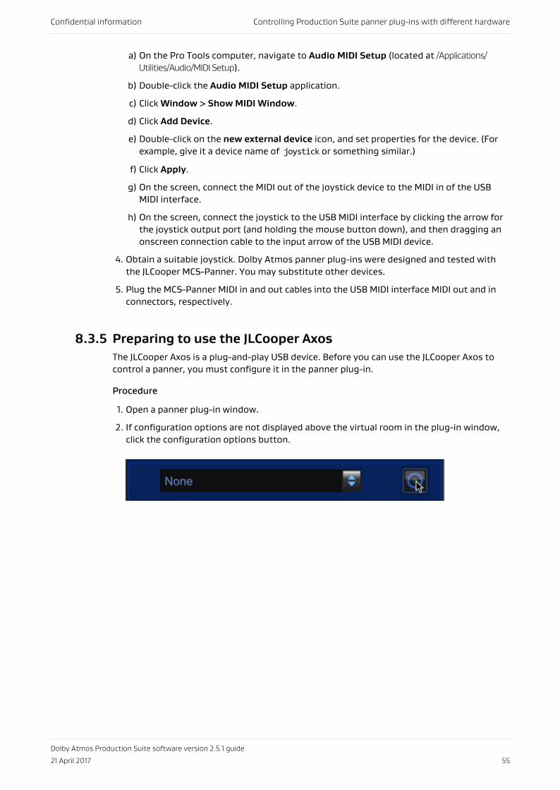
a) On the Pro Tools computer, navigate to Audio MIDI Setup (located at /Applications/Utilities/Audio/MIDI Setup).
b) Double-click the Audio MIDI Setup application.
c) Click Window > Show MIDI Window.
d) Click Add Device.
e) Double-click on the new external device icon, and set properties for the device. (Forexample, give it a device name of joystick or something similar.)
f) Click Apply.
g) On the screen, connect the MIDI out of the joystick device to the MIDI in of the USBMIDI interface.
h) On the screen, connect the joystick to the USB MIDI interface by clicking the arrow forthe joystick output port (and holding the mouse button down), and then dragging anonscreen connection cable to the input arrow of the USB MIDI device.
4. Obtain a suitable joystick. Dolby Atmos panner plug-ins were designed and tested withthe JLCooper MCS-Panner. You may substitute other devices.
5. Plug the MCS-Panner MIDI in and out cables into the USB MIDI interface MIDI out and inconnectors, respectively.
8.3.5 Preparing to use the JLCooper AxosThe JLCooper Axos is a plug-and-play USB device. Before you can use the JLCooper Axos tocontrol a panner, you must configure it in the panner plug-in.
Procedure
1. Open a panner plug-in window.
2. If configuration options are not displayed above the virtual room in the plug-in window,click the configuration options button.
Confidential information Controlling Production Suite panner plug-ins with different hardware
Dolby Atmos Production Suite software version 2.5.1 guide
21 April 2017 55
3. In the Object section, verify that there is an object number. If a new object number isneeded, assign one.
4. In the Joystick Device section, use the joystick device input and output selectors to selectJLCooper Axos Panner as the input and output device.
5. Test the connection by moving the Axos (or using the Axos switches and knobs todetermine other panner behaviors). The yellow dot in the plug-in should move as the Axosis moved.
6. To close the configuration options section, click the configuration options button.
7. Repeat the preceding steps, and configure the JLCooper Axos in each of the remainingpanner plug-ins in the session.
8.3.6 Installing the JLCooper Eclipse PX joystickBefore you can configure the JLCooper Eclipse PX to control the panner, you must first installit on the computer running Pro Tools.
Procedure
1. Download the latest JLCooper Nuage Panner/Eclipse PX software for Mac OS X from the www.jlcooper.com.
The Eclipse PX is the same hardware as the Nuage panner for Yamaha/Steinberg mixingconsoles. The name of the installer package is Nuage Panner/Eclipse PX software for OS Xversion 1.0.3.
2. Launch the installer file, and follow the onscreen instructions to drag the panner icon intothe applications icon.
3. To connect the controller to your Mac through a router, perform these steps:
a) Connect the controller to your network router, and then turn on the controller.
b) In the Applications folder, locate the JLCooper Nuage Panner-Eclipse PX folder andopen it.
c) Launch the JLCooper Nuage Panner-Eclipse PX setup application. If prompted with anerror message about installing required software components, ignore the messageand press Go Back to resume installation.
d) In the Nuage Panner/Eclipse PX Setup dialog, click (highlight) the network interfacefor your panner and click Locate Panners to find your panner address, or, if you knowyour panner address, click Manual IP Address and enter your address.
e) Follow the onscreen instructions to finish connecting the software to your controller.When done, click Finish. If you want to connect the controller directly to yourcomputer through a dedicated Ethernet port, refer to documentation included withthe JLCooper Nuage Panner-Eclipse PX software package.
4. Verify that the controller is an active MIDI device in the Apple Audio MIDI Setup utility:
Confidential information Controlling Production Suite panner plug-ins with different hardware
Dolby Atmos Production Suite software version 2.5.1 guide
21 April 2017 56
a) On the Pro Tools computer, navigate to Audio MIDI Setup (located at /Applications/Utilities/Audio/MIDI Setup).
b) Double-click the Audio MIDI Setup application.
c) Click Window > Show MIDI Studio.
d) If the controller is not present, close active windows and dialogs, and then reboot theMac.
e) If the controller is present, but not active, press the Rescan MIDI button. When youlaunch Pro Tools, the Eclipse PX shows Pro in its Pro display. The controller will beavailable in the Joystick Device menu in the Dolby Atmos Panner plug-in after youinsert the plug-in on a track.
What to do nextConfigure the JLCooper Eclipse PX joystick.
8.3.7 Configuring a JLCooper Eclipse PX joystick in a panner plug-inBefore you can use a JLCooper Eclipse PX joystick to control a panner, you must configure thejoystick in the panner plug-in.
PrerequisitesEnsure that the JLCooper Eclipse PX joystick is installed on the computer running Pro Tools.
Procedure
1. Open a panner plug-in window.
2. If configuration options are not displayed above the virtual room in the plug-in window,click the configuration options button.
3. In the Object section, verify that there is an object number. If a new input channelnumber is needed, assign one.
4. In the Joystick Device section, use the joystick device input and output selectors to selectNuage Panner/Eclipse PX as the input and output device.
5. Test the connection by clicking the button on top of the joystick, and then move thejoystick. The yellow dot in the plug-in should move as the joystick is moved.
6. Repeat the preceding steps, and configure the joystick in each of the remaining pannerplug-ins in the session.
7. To close the configuration options section, click the configuration options button.
8.4 Control surface and mixing console supportFrom a control surface or mixing console qualified by Dolby, you can map panner plug-incontrols to physical controls.
About this task
After mapping controls, you can then edit and automate parameters from the controlsurface or console.
Refer to your control-surface or console documentation for detailed information on how touse it to control standard plug-in features.
You can use the panner with most control surfaces and mixing consoles that support pagetables (such as an Avid control surface).
Confidential information Controlling Production Suite panner plug-ins with different hardware
Dolby Atmos Production Suite software version 2.5.1 guide
21 April 2017 57
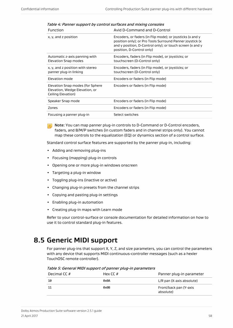
Table 4: Panner support by control surfaces and mixing consolesFunction Avid D-Command and D-Control
x, y, and z position Encoders, or faders (in Flip mode); or joysticks (x and yposition only); or Pro Tools Surround Panner joystick (xand y position, D-Control only); or touch screen (x and yposition, D-Control only)
Automatic z-axis panning withElevation Snap modes
Encoders, faders (in Flip mode), or joysticks; ortouchscreen (D-Control only)
x, y, and z position with stereopanner plug-in linking
Encoders, faders (in Flip mode), or joysticks; ortouchscreen (D-Control only)
Elevation mode Encoders or faders (in Flip mode)
Elevation Snap modes (for SphereElevation, Wedge Elevation, orCeiling Elevation)
Encoders or faders (in Flip mode)
Speaker Snap mode Encoders or faders (in Flip mode)
Zones Encoders or faders (in Flip mode)
Focusing a panner plug-in Select switches
Note: You can map panner plug-in controls to D-Command or D-Control encoders,faders, and B/M/P switches (in custom faders and in channel strips only). You cannotmap these controls to the equalization (EQ) or dynamics section of a control surface.
Standard control surface features are supported by the panner plug-in, including:
• Adding and removing plug-ins
• Focusing (mapping) plug-in controls
• Opening one or more plug-in windows onscreen
• Targeting a plug-in window
• Toggling plug-ins (inactive or active)
• Changing plug-in presets from the channel strips
• Copying and pasting plug-in settings
• Enabling plug-in automation
• Creating plug-in maps with Learn mode
Refer to your control-surface or console documentation for detailed information on how touse it to control standard plug-in features.
8.5 Generic MIDI supportFor panner plug-ins that support X, Y, Z, and size parameters, you can control the parameterswith any device that supports MIDI continuous-controller messages (such as a hexlerTouchOSC remote controller).
Table 5: General MIDI support of panner plug-in parametersDecimal CC # Hex CC # Panner plug-in parameter
10 0x0A L/R pan (X-axis absolute)
11 0x0B Front/back pan (Y-axisabsolute)
Confidential information Controlling Production Suite panner plug-ins with different hardware
Dolby Atmos Production Suite software version 2.5.1 guide
21 April 2017 58
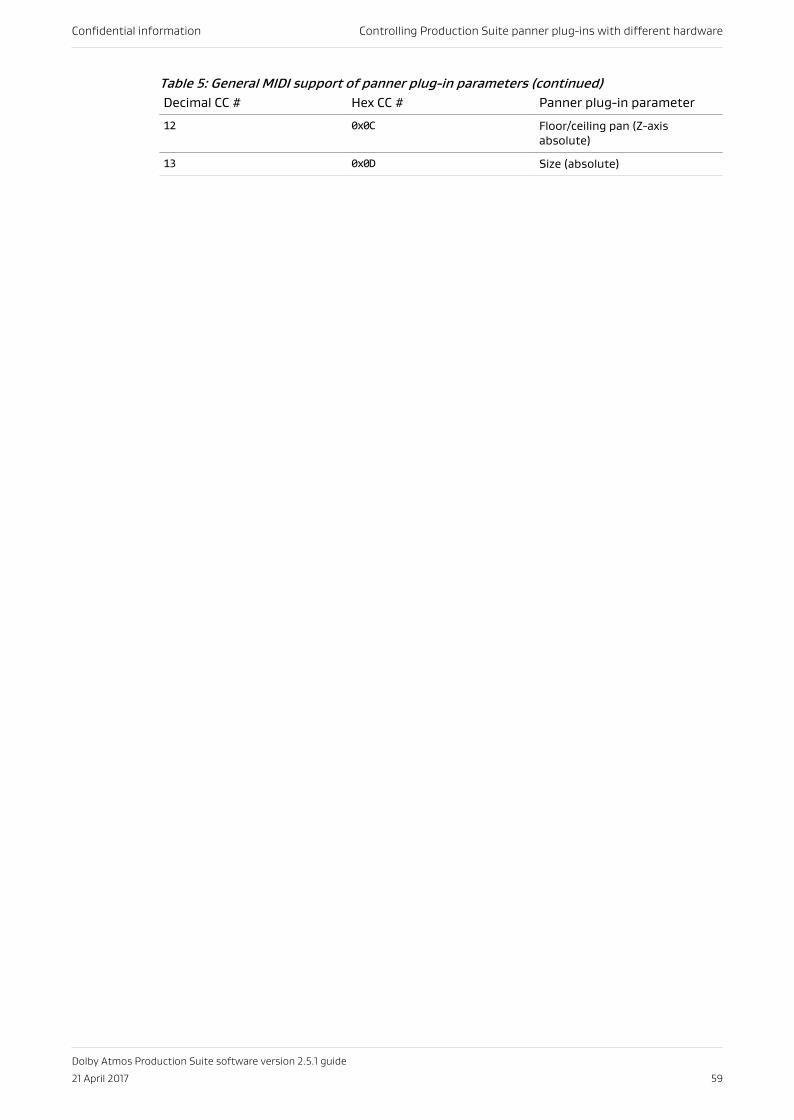
Table 5: General MIDI support of panner plug-in parameters (continued)Decimal CC # Hex CC # Panner plug-in parameter
12 0x0C Floor/ceiling pan (Z-axisabsolute)
13 0x0D Size (absolute)
Confidential information Controlling Production Suite panner plug-ins with different hardware
Dolby Atmos Production Suite software version 2.5.1 guide
21 April 2017 59
9 Rendering to the Dolby AtmosformatUse the Dolby Atmos Production Suite to render Dolby Atmos content.
• Overview of rendering• Live monitoring a Dolby Atmos mix• Playing back a master or other Dolby Atmos media file
9.1 Overview of renderingRendering refers to the process and algorithms that the Dolby Atmos Renderer uses torender (or play) audio beds and objects while positioning them to, or across, up to 34speakers. Positioning for beds is based on multichannel mixes in Pro Tools. Positioning forobjects is based on Dolby Atmos metadata, as defined by Production Suite panner plug-ins inPro Tools.
The Renderer supports rendering to the Dolby Atmos format when listening to a mix (livemonitoring), recording a master, punching in and out of a master, or playing back a master.
• During monitoring (live monitoring): Renders audio and metadata from Pro Tools and anyclient applications
• During mastering: Renders audio and metadata from Pro Tools and any clientapplications, and captures the full set of audio and metadata signals to hard disk drive tocreate the master
• During playback: Renders material from the master
Note: Pro Tools Aggregate and Built-In output audio devices can intermittently, andwithout warning, change the sampling rate to 44.1 kHz (typically, after a CPU overload).This sample rate change causes rendered audio to be jittery. As a workaround, open theMac OS X Audio MIDI Setup application and select the 48 kHz sample rate. If 48 kHz isalready selected, unselect it, and then reselect it.
9.2 Live monitoring a Dolby Atmos mixYou can monitor a rendered Dolby Atmos mix from your system outputs.
Prerequisites
Your Pro Tools session is configured for Dolby Atmos rendering.
About this task
You can monitor the rendered Dolby Atmos audio when mixing and listening live to Pro Toolsmaterial in the Dolby Atmos format, or in a channel-based surround format (such as 7.1 or 5.1channels).
Additionally, you can monitor the mix during setup, for example, when adjusting monitoringsettings, or applying equalization to the default (flat) equalization setting.
Confidential information Rendering to the Dolby Atmos format
Dolby Atmos Production Suite software version 2.5.1 guide
21 April 2017 60
Procedure
1. When you are ready to monitor the system output, start playback in the Pro Toolssession.
2. When done, stop playback in Pro Tools.
9.3 Playing back a master or other Dolby Atmosmedia fileYou can play back (or monitor playback of) a supported Dolby Atmos media file. This includesan .atmos (or .damf) master file set, as well as an ADM BWF file, cinema print master (.rpl) file,encoded .mxf file, or pmstitch .xml file.
Prerequisites
A Pro Tools session is open so that the transport play and stop controls and the timelinelocation controls are available.
About this task
The master that plays back is specified in the mastering screen.
The Pro Tools transport triggers playback. Typically, you will use the Pro Tools session thatwas used to create the master to locate and trigger where on the timeline to begin playback.If you use a different session, you may need to adjust the start time in Pro Tools to align withthe start time in the master.
When playing back an .mxf file, the Renderer always starts playback at frame 1 (timecode00:00).
This task does not use Dolby Renderer Send plug-ins.
Procedure
1. In the Renderer window, choose Mastering in the navigation bar to open the masteringscreen.
2. Select or type in the path and file name of the master file set in the Master File field.
3. Click Set to load the master.
• By default, the master loads in Read Only mode to prevent accidentally overwritingmaterial with a punch recording.
• The timecode rate shown in the FPS field automatically updates to the mastertimecode rate.
• The Master button automatically enables (if it was previously disabled).
4. Ensure that the Master button in the status and control section is enabled.
With a master loaded and the Renderer in master mode, you can play back the master.
5. In Pro Tools, start playback at or before the master start time (which is shown in the Startdisplay in the Master Playback and Recording Operations section of the masteringscreen).
The master plays back when the Pro Tools timeline location is at or between the start andend times of the master, as displayed in the Master Playback and Recording Operationssection.
Confidential information Rendering to the Dolby Atmos format
Dolby Atmos Production Suite software version 2.5.1 guide
21 April 2017 61
Note: If you use a session other than the one that was used to create the master, youmay need to adjust the start time in Pro Tools Session Setup to align with the starttime in the master.
6. When done, stop playback in Pro Tools.
Confidential information Rendering to the Dolby Atmos format
Dolby Atmos Production Suite software version 2.5.1 guide
21 April 2017 62
10 Recording Dolby Atmos contentUse the Dolby Atmos Production Suite to record Dolby Atmos content.
• Recording a bounded master• Recording an unbounded master• Punching in and out of a master recording at set points• Punching in and out of a master recording manually• Paths and file names for a master file set• Deleting master media
10.1 Recording a bounded masterYou can record a bounded master (a section of your Dolby Atmos mix) as it plays back in ProTools. Prior to recording, you set the in and out points of the master to create a boundedmaster.
Prerequisites
• Your Pro Tools session is configured for Dolby Atmos rendering.
• You have a Dolby Atmos mix ready to record as a master.
• When recording a master, or doing a punch in and out, we recommend disabling re-renders. Re-renders with groups consume CPU usage and can potentially affect a liverecording.
About this taskThe Renderer records a master, which is a set of files (a master file set), to a folder specifiedin the mastering screen.
The recorded master:
• Contains bed audio, object audio, and Dolby Atmos metadata.
• Does not include spatial encoding information. Spatial coding is added back to thematerial during encoding. For home theater masters, you can encode with the DolbyMedia Encoder. For VR masters, you can encode with the Dolby Atmos VR Transcoder. Formore information, see the documentation included with your encoder software.
Alternatively, you can record an unbounded master (without set in and out points).
Procedure
1. If the Renderer is not open, launch it.
2. In the top section of the Renderer, select a timecode rate in the FPS drop-down menu.
The rate must match the rate of the Pro Tools session.
3. Choose Mastering in the navigation bar to open the mastering screen.
4. In the Master File field, select or type in the path for the master file set.
The default name of the output.atmos file will be added automatically when you set the filepath in the next step.
5. Click Set to set the location and file name, and place the Renderer in Read/Write mode.
Confidential information Recording Dolby Atmos content
Dolby Atmos Production Suite software version 2.5.1 guide
21 April 2017 63
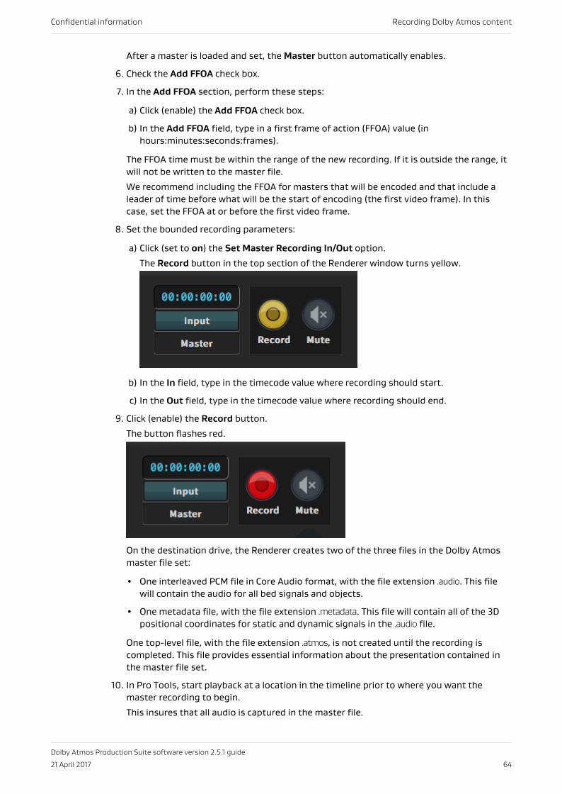
After a master is loaded and set, the Master button automatically enables.
6. Check the Add FFOA check box.
7. In the Add FFOA section, perform these steps:
a) Click (enable) the Add FFOA check box.
b) In the Add FFOA field, type in a first frame of action (FFOA) value (inhours:minutes:seconds:frames).
The FFOA time must be within the range of the new recording. If it is outside the range, itwill not be written to the master file.
We recommend including the FFOA for masters that will be encoded and that include aleader of time before what will be the start of encoding (the first video frame). In thiscase, set the FFOA at or before the first video frame.
8. Set the bounded recording parameters:
a) Click (set to on) the Set Master Recording In/Out option.
The Record button in the top section of the Renderer window turns yellow.
b) In the In field, type in the timecode value where recording should start.
c) In the Out field, type in the timecode value where recording should end.
9. Click (enable) the Record button.
The button flashes red.
On the destination drive, the Renderer creates two of the three files in the Dolby Atmosmaster file set:
• One interleaved PCM file in Core Audio format, with the file extension .audio. This filewill contain the audio for all bed signals and objects.
• One metadata file, with the file extension .metadata. This file will contain all of the 3Dpositional coordinates for static and dynamic signals in the .audio file.
One top-level file, with the file extension .atmos, is not created until the recording iscompleted. This file provides essential information about the presentation contained inthe master file set.
10. In Pro Tools, start playback at a location in the timeline prior to where you want themaster recording to begin.
This insures that all audio is captured in the master file.
Confidential information Recording Dolby Atmos content
Dolby Atmos Production Suite software version 2.5.1 guide
21 April 2017 64
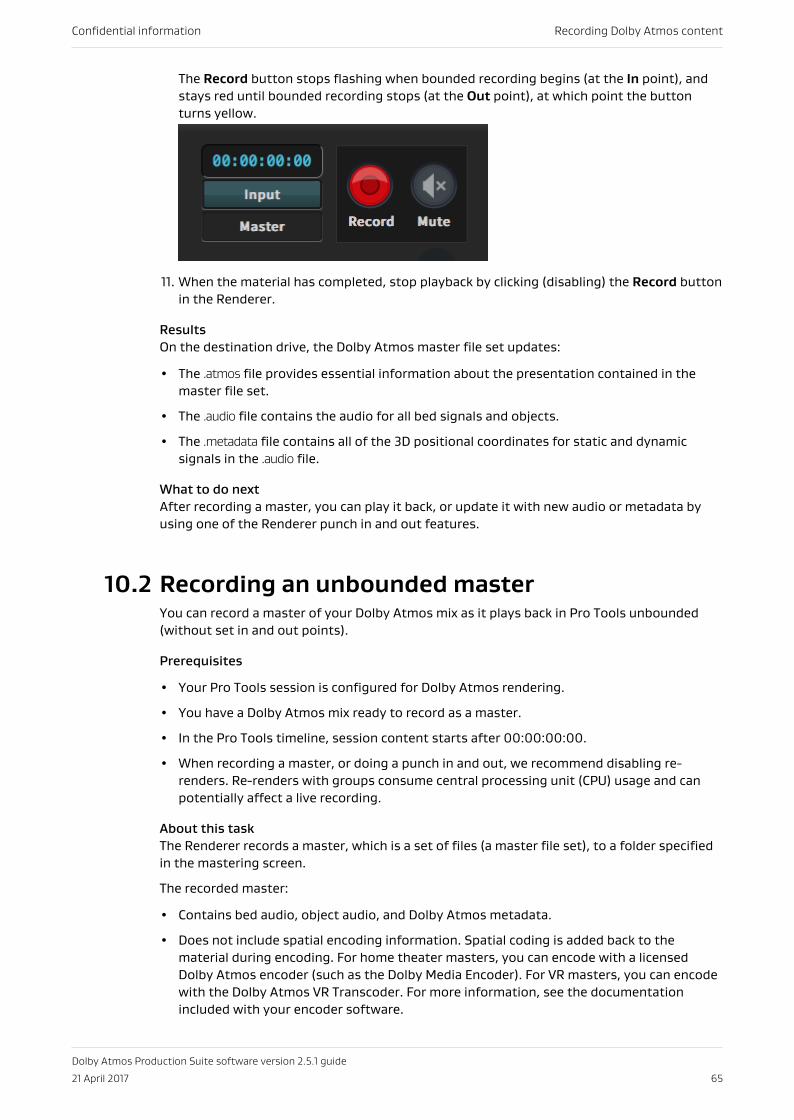
The Record button stops flashing when bounded recording begins (at the In point), andstays red until bounded recording stops (at the Out point), at which point the buttonturns yellow.
11. When the material has completed, stop playback by clicking (disabling) the Record buttonin the Renderer.
ResultsOn the destination drive, the Dolby Atmos master file set updates:
• The .atmos file provides essential information about the presentation contained in themaster file set.
• The .audio file contains the audio for all bed signals and objects.
• The .metadata file contains all of the 3D positional coordinates for static and dynamicsignals in the .audio file.
What to do nextAfter recording a master, you can play it back, or update it with new audio or metadata byusing one of the Renderer punch in and out features.
10.2 Recording an unbounded masterYou can record a master of your Dolby Atmos mix as it plays back in Pro Tools unbounded(without set in and out points).
Prerequisites
• Your Pro Tools session is configured for Dolby Atmos rendering.
• You have a Dolby Atmos mix ready to record as a master.
• In the Pro Tools timeline, session content starts after 00:00:00:00.
• When recording a master, or doing a punch in and out, we recommend disabling re-renders. Re-renders with groups consume central processing unit (CPU) usage and canpotentially affect a live recording.
About this taskThe Renderer records a master, which is a set of files (a master file set), to a folder specifiedin the mastering screen.
The recorded master:
• Contains bed audio, object audio, and Dolby Atmos metadata.
• Does not include spatial encoding information. Spatial coding is added back to thematerial during encoding. For home theater masters, you can encode with a licensedDolby Atmos encoder (such as the Dolby Media Encoder). For VR masters, you can encodewith the Dolby Atmos VR Transcoder. For more information, see the documentationincluded with your encoder software.
Confidential information Recording Dolby Atmos content
Dolby Atmos Production Suite software version 2.5.1 guide
21 April 2017 65
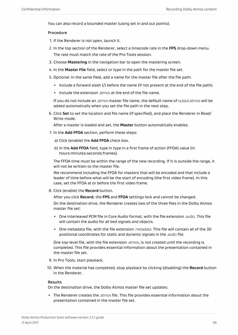
You can also record a bounded master (using set in and out points).
Procedure
1. If the Renderer is not open, launch it.
2. In the top section of the Renderer, select a timecode rate in the FPS drop-down menu.
The rate must match the rate of the Pro Tools session.
3. Choose Mastering in the navigation bar to open the mastering screen.
4. In the Master File field, select or type in the path for the master file set.
5. Optional: In the same field, add a name for the master file after the file path:
• Include a forward slash (/) before the name (if not present at the end of the file path).
• Include the extension .atmos at the end of the file name.
If you do not include an .atmos master file name, the default name of output.atmos will beadded automatically when you set the file path in the next step.
6. Click Set to set the location and file name (if specified), and place the Renderer in Read/Write mode.
After a master is loaded and set, the Master button automatically enables.
7. In the Add FFOA section, perform these steps:
a) Click (enable) the Add FFOA check box.
b) In the Add FFOA field, type in type in a first frame of action (FFOA) value (inhours:minutes:seconds:frames).
The FFOA time must be within the range of the new recording. If it is outside the range, itwill not be written to the master file.
We recommend including the FFOA for masters that will be encoded and that include aleader of time before what will be the start of encoding (the first video frame). In thiscase, set the FFOA at or before the first video frame.
8. Click (enable) the Record button.
After you click Record, the FPS and FFOA settings lock and cannot be changed.
On the destination drive, the Renderer creates two of the three files in the Dolby Atmosmaster file set:
• One interleaved PCM file in Core Audio format, with the file extension .audio. This filewill contain the audio for all bed signals and objects.
• One metadata file, with the file extension .metadata. This file will contain all of the 3Dpositional coordinates for static and dynamic signals in the .audio file.
One top-level file, with the file extension .atmos, is not created until the recording iscompleted. This file provides essential information about the presentation contained inthe master file set.
9. In Pro Tools, start playback.
10. When the material has completed, stop playback by clicking (disabling) the Record buttonin the Renderer.
ResultsOn the destination drive, the Dolby Atmos master file set updates:
• The Renderer creates the .atmos file. This file provides essential information about thepresentation contained in the master file set.
Confidential information Recording Dolby Atmos content
Dolby Atmos Production Suite software version 2.5.1 guide
21 April 2017 66
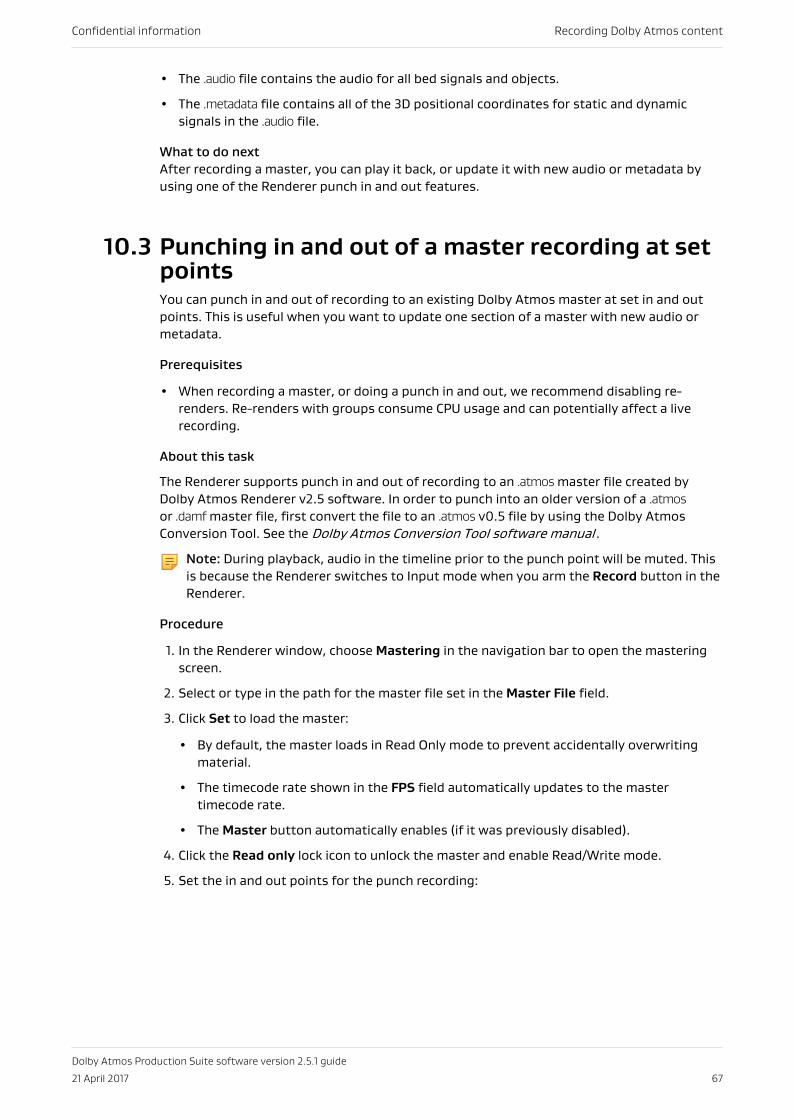
• The .audio file contains the audio for all bed signals and objects.
• The .metadata file contains all of the 3D positional coordinates for static and dynamicsignals in the .audio file.
What to do nextAfter recording a master, you can play it back, or update it with new audio or metadata byusing one of the Renderer punch in and out features.
10.3 Punching in and out of a master recording at setpointsYou can punch in and out of recording to an existing Dolby Atmos master at set in and outpoints. This is useful when you want to update one section of a master with new audio ormetadata.
Prerequisites
• When recording a master, or doing a punch in and out, we recommend disabling re-renders. Re-renders with groups consume CPU usage and can potentially affect a liverecording.
About this task
The Renderer supports punch in and out of recording to an .atmos master file created byDolby Atmos Renderer v2.5 software. In order to punch into an older version of a .atmosor .damf master file, first convert the file to an .atmos v0.5 file by using the Dolby AtmosConversion Tool. See the Dolby Atmos Conversion Tool software manual .
Note: During playback, audio in the timeline prior to the punch point will be muted. Thisis because the Renderer switches to Input mode when you arm the Record button in theRenderer.
Procedure
1. In the Renderer window, choose Mastering in the navigation bar to open the masteringscreen.
2. Select or type in the path for the master file set in the Master File field.
3. Click Set to load the master:
• By default, the master loads in Read Only mode to prevent accidentally overwritingmaterial.
• The timecode rate shown in the FPS field automatically updates to the mastertimecode rate.
• The Master button automatically enables (if it was previously disabled).
4. Click the Read only lock icon to unlock the master and enable Read/Write mode.
5. Set the in and out points for the punch recording:
Confidential information Recording Dolby Atmos content
Dolby Atmos Production Suite software version 2.5.1 guide
21 April 2017 67
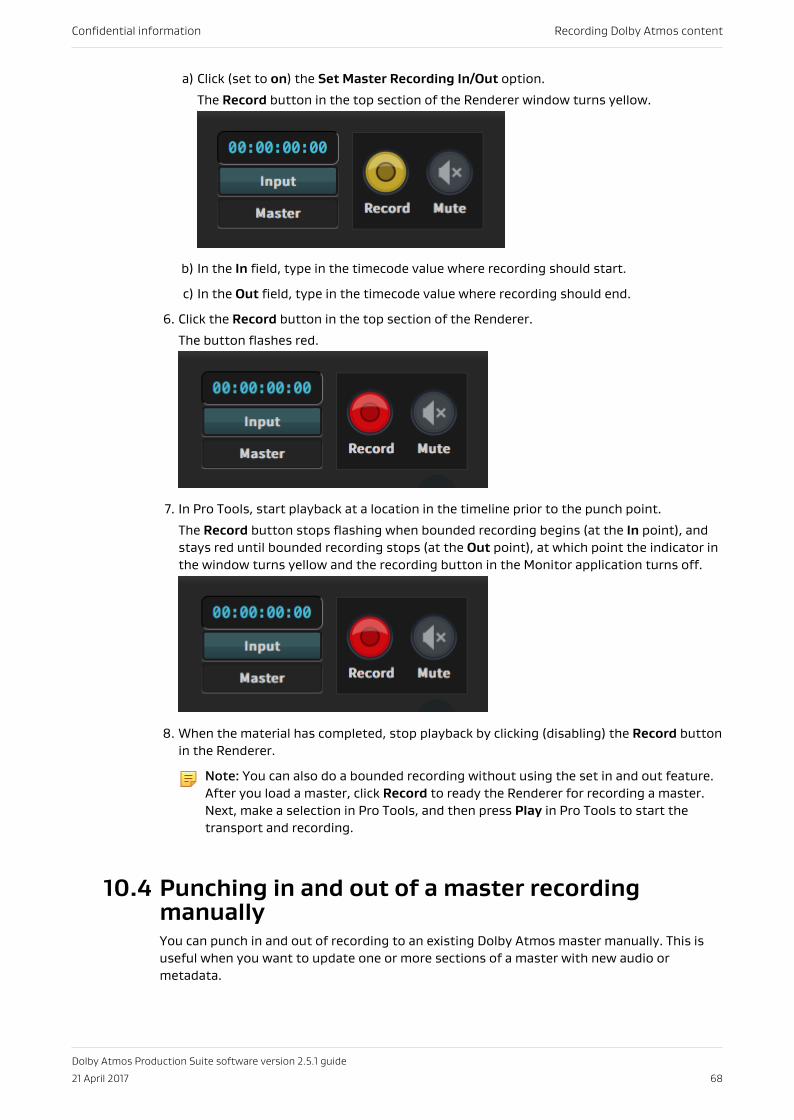
a) Click (set to on) the Set Master Recording In/Out option.
The Record button in the top section of the Renderer window turns yellow.
b) In the In field, type in the timecode value where recording should start.
c) In the Out field, type in the timecode value where recording should end.
6. Click the Record button in the top section of the Renderer.
The button flashes red.
7. In Pro Tools, start playback at a location in the timeline prior to the punch point.
The Record button stops flashing when bounded recording begins (at the In point), andstays red until bounded recording stops (at the Out point), at which point the indicator inthe window turns yellow and the recording button in the Monitor application turns off.
8. When the material has completed, stop playback by clicking (disabling) the Record buttonin the Renderer.
Note: You can also do a bounded recording without using the set in and out feature.After you load a master, click Record to ready the Renderer for recording a master.Next, make a selection in Pro Tools, and then press Play in Pro Tools to start thetransport and recording.
10.4 Punching in and out of a master recordingmanuallyYou can punch in and out of recording to an existing Dolby Atmos master manually. This isuseful when you want to update one or more sections of a master with new audio ormetadata.
Confidential information Recording Dolby Atmos content
Dolby Atmos Production Suite software version 2.5.1 guide
21 April 2017 68
Prerequisites
• Before performing a punch in and out recording pass, do not add new objects to the ProTools session. If you need to add new objects to the session, record a new master withthe new objects before performing the punch in and out.
• When recording a master, or doing a punch in and out, we recommend disabling re-renders. Re-renders with groups consume CPU usage and can potentially affect a liverecording.
About this task
The Renderer supports punch in and out of recording to an .atmos master file created byDolby Atmos Renderer v2.5 software. In order to punch into an older version of a .atmosor .damf master file, first convert the file to an .atmos v0.5 file by using the Dolby AtmosConversion Tool. See the Dolby Atmos Conversion Tool software manual .
When punching in and out of recording a master:
• The first punch-in creates the new master and determines the beginning of the recording.You cannot subsequently punch in before the time of the first punch.
• If you are recording to an existing master, you can start from anywhere in the timeline aslong you do not punch in before or after the master start and end times.
• It is not possible to have gaps in the file. Punch-ins must be performed in a linear fashion.You cannot jump to a later point in the timeline and punch in or out.
Procedure
1. In the Renderer window, choose Mastering in the navigation bar to open the masteringscreen.
2. Select or type in the path for the master file set in the Master File field.
3. Click Set to load the master.
• By default, the master loads in Read Only mode to prevent accidentally overwritingmaterial.
• The timecode rate shown in the FPS field automatically updates to the mastertimecode rate
• The Master button automatically enables, if it was previously disabled.
4. Click the Read only lock icon to unlock the master and enable Read/Write mode.
5. In Pro Tools, start playback at a location in the timeline prior to the punch point.
For example, in Pro Tools, place the cursor in the timeline prior to where you intend topunch in, and then start playback.
6. In the Renderer, punch in and out of recording:
a) Click (highlight) the Record button to begin recording.
b) When done recording, click (disable) Record to punch out of recording.
c) Continue to click (highlight) Record to punch in, and then again to punch out, asneeded.
10.5 Paths and file names for a master file setIn the mastering screen, the Master File field defines the path and names used whenrecording a master file.
Confidential information Recording Dolby Atmos content
Dolby Atmos Production Suite software version 2.5.1 guide
21 April 2017 69
The presence of the final forward slash (/) defines whether the last entry in a path is adirectory or file name. If the last entry does not have a final forward slash, it is treated as auser-defined file name.
For example, specifying a <path>/<name>/ with an ending forward slash (/) records to the<name> subdirectory with the default file name (output) before the extensions for eachmaster file. The <path>/<name>/ is created if it does not exist. In this example, the three filesin the master file set are recorded:
The .audio file records to <path>/<name>/output.atmos.audio.The .metadata file records to <path>/<name>/output.atmos.metadata.The .atmos file records to <path>/<name>/output.atmos.
Specifying the last entry with no ending forward slash (/) records to the path and the customfile name before the extensions for each master file. These examples show the path and filename for the top-level file in the master file set (.atmos):
<path>/<name> records to <path>/<name>.atmos.<path>/<name.xxx> records to <path>/<name.xxx>.atmos.<path>/<name>.atmos records to <path>/<name>.atmos>.
10.6 Deleting master mediaRecorded masters cannot be deleted from the Renderer application. They can be deleteddirectly from their media drive only.
Procedure
1. Locate the master folder on the media drive.
2. Manually delete the folders and its files.
Confidential information Recording Dolby Atmos content
Dolby Atmos Production Suite software version 2.5.1 guide
21 April 2017 70
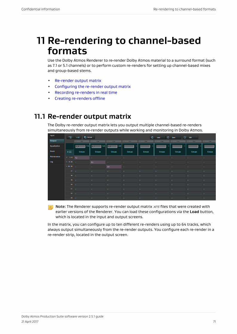
11 Re-rendering to channel-basedformatsUse the Dolby Atmos Renderer to re‐render Dolby Atmos material to a surround format (suchas 7.1 or 5.1 channels) or to perform custom re-renders for setting up channel-based mixesand group-based stems.
• Re-render output matrix• Configuring the re-render output matrix• Recording re-renders in real time• Creating re-renders offline
11.1 Re-render output matrixThe Dolby re-render output matrix lets you output multiple channel-based re-renderssimultaneously from re-render outputs while working and monitoring in Dolby Atmos.
Note: The Renderer supports re-render output matrix .xml files that were created withearlier versions of the Renderer. You can load these configurations via the Load button,which is located in the input and output screens.
In the matrix, you can configure up to ten different re-renders using up to 64 tracks, whichalways output simultaneously from the re-render outputs. You configure each re-render in are-render strip, located in the output screen.
Confidential information Re-rendering to channel-based formats
Dolby Atmos Production Suite software version 2.5.1 guide
21 April 2017 71
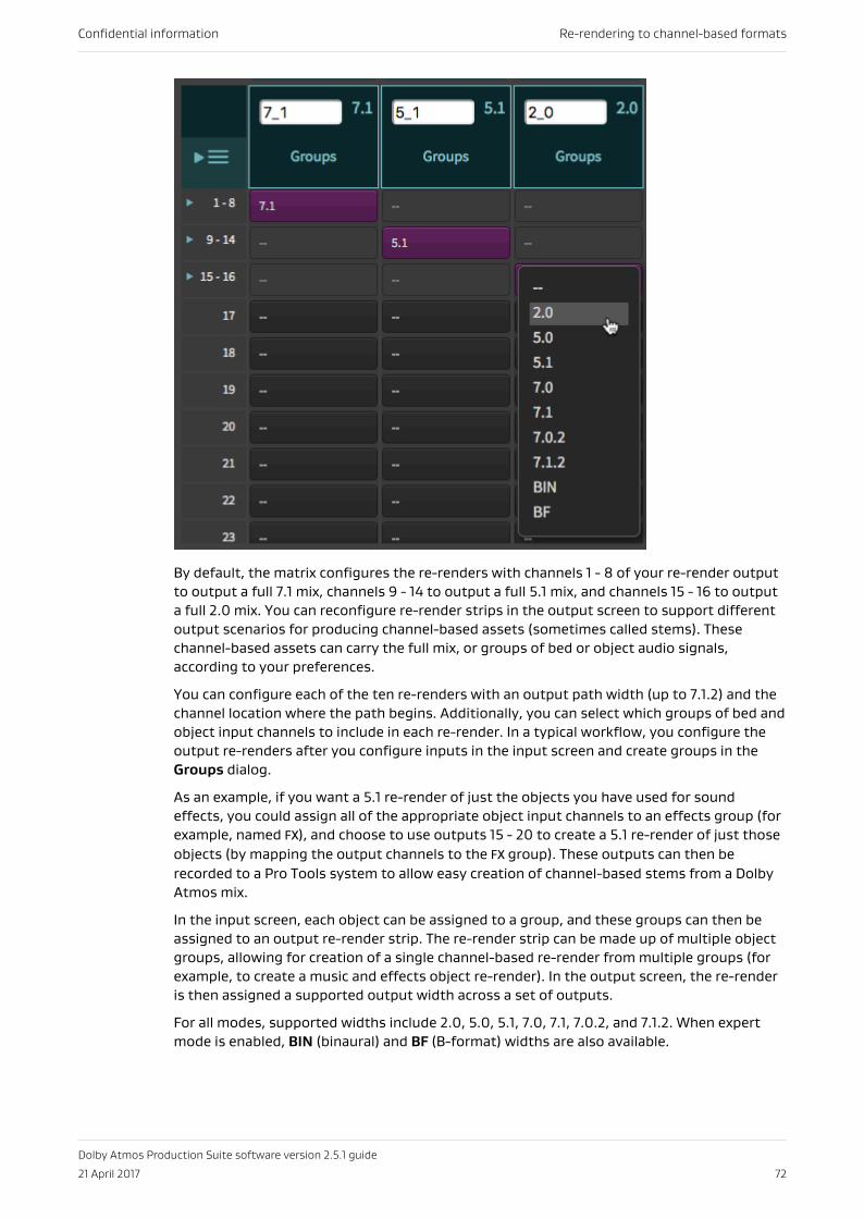
By default, the matrix configures the re-renders with channels 1 - 8 of your re-render outputto output a full 7.1 mix, channels 9 - 14 to output a full 5.1 mix, and channels 15 - 16 to outputa full 2.0 mix. You can reconfigure re-render strips in the output screen to support differentoutput scenarios for producing channel-based assets (sometimes called stems). Thesechannel-based assets can carry the full mix, or groups of bed or object audio signals,according to your preferences.
You can configure each of the ten re-renders with an output path width (up to 7.1.2) and thechannel location where the path begins. Additionally, you can select which groups of bed andobject input channels to include in each re-render. In a typical workflow, you configure theoutput re-renders after you configure inputs in the input screen and create groups in theGroups dialog.
As an example, if you want a 5.1 re-render of just the objects you have used for soundeffects, you could assign all of the appropriate object input channels to an effects group (forexample, named FX), and choose to use outputs 15 - 20 to create a 5.1 re-render of just thoseobjects (by mapping the output channels to the FX group). These outputs can then berecorded to a Pro Tools system to allow easy creation of channel-based stems from a DolbyAtmos mix.
In the input screen, each object can be assigned to a group, and these groups can then beassigned to an output re-render strip. The re-render strip can be made up of multiple objectgroups, allowing for creation of a single channel-based re-render from multiple groups (forexample, to create a music and effects object re-render). In the output screen, the re-renderis then assigned a supported output width across a set of outputs.
For all modes, supported widths include 2.0, 5.0, 5.1, 7.0, 7.1, 7.0.2, and 7.1.2. When expertmode is enabled, BIN (binaural) and BF (B-format) widths are also available.
Confidential information Re-rendering to channel-based formats
Dolby Atmos Production Suite software version 2.5.1 guide
21 April 2017 72
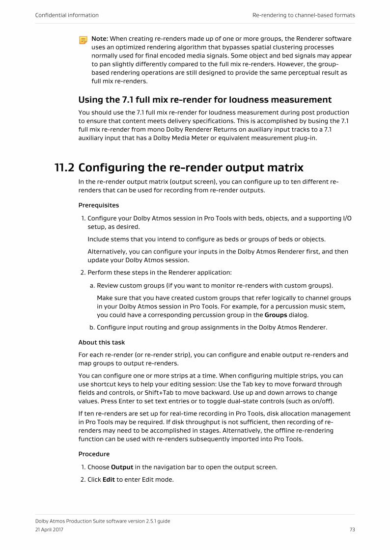
Note: When creating re-renders made up of one or more groups, the Renderer softwareuses an optimized rendering algorithm that bypasses spatial clustering processesnormally used for final encoded media signals. Some object and bed signals may appearto pan slightly differently compared to the full mix re-renders. However, the group-based rendering operations are still designed to provide the same perceptual result asfull mix re-renders.
Using the 7.1 full mix re-render for loudness measurementYou should use the 7.1 full mix re-render for loudness measurement during post productionto ensure that content meets delivery specifications. This is accomplished by busing the 7.1full mix re-render from mono Dolby Renderer Returns on auxiliary input tracks to a 7.1auxiliary input that has a Dolby Media Meter or equivalent measurement plug-in.
11.2 Configuring the re-render output matrixIn the re-render output matrix (output screen), you can configure up to ten different re-renders that can be used for recording from re-render outputs.
Prerequisites
1. Configure your Dolby Atmos session in Pro Tools with beds, objects, and a supporting I/Osetup, as desired.
Include stems that you intend to configure as beds or groups of beds or objects.
Alternatively, you can configure your inputs in the Dolby Atmos Renderer first, and thenupdate your Dolby Atmos session.
2. Perform these steps in the Renderer application:
a. Review custom groups (if you want to monitor re-renders with custom groups).
Make sure that you have created custom groups that refer logically to channel groupsin your Dolby Atmos session in Pro Tools. For example, for a percussion music stem,you could have a corresponding percussion group in the Groups dialog.
b. Configure input routing and group assignments in the Dolby Atmos Renderer.
About this task
For each re-render (or re-render strip), you can configure and enable output re-renders andmap groups to output re-renders.
You can configure one or more strips at a time. When configuring multiple strips, you canuse shortcut keys to help your editing session: Use the Tab key to move forward throughfields and controls, or Shift+Tab to move backward. Use up and down arrows to changevalues. Press Enter to set text entries or to toggle dual-state controls (such as on/off).
If ten re-renders are set up for real-time recording in Pro Tools, disk allocation managementin Pro Tools may be required. If disk throughput is not sufficient, then recording of re-renders may need to be accomplished in stages. Alternatively, the offline re-renderingfunction can be used with re-renders subsequently imported into Pro Tools.
Procedure
1. Choose Output in the navigation bar to open the output screen.
2. Click Edit to enter Edit mode.
Confidential information Re-rendering to channel-based formats
Dolby Atmos Production Suite software version 2.5.1 guide
21 April 2017 73
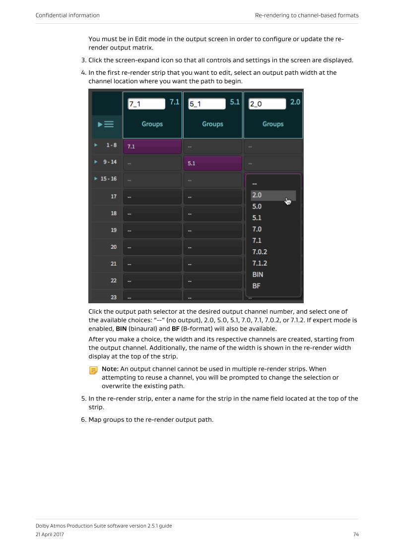
You must be in Edit mode in the output screen in order to configure or update the re-render output matrix.
3. Click the screen-expand icon so that all controls and settings in the screen are displayed.
4. In the first re-render strip that you want to edit, select an output path width at thechannel location where you want the path to begin.
Click the output path selector at the desired output channel number, and select one ofthe available choices: “--” (no output), 2.0, 5.0, 5.1, 7.0, 7.1, 7.0.2, or 7.1.2. If expert mode isenabled, BIN (binaural) and BF (B-format) will also be available.
After you make a choice, the width and its respective channels are created, starting fromthe output channel. Additionally, the name of the width is shown in the re-render widthdisplay at the top of the strip.
Note: An output channel cannot be used in multiple re-render strips. Whenattempting to reuse a channel, you will be prompted to change the selection oroverwrite the existing path.
5. In the re-render strip, enter a name for the strip in the name field located at the top of thestrip.
6. Map groups to the re-render output path.
Confidential information Re-rendering to channel-based formats
Dolby Atmos Production Suite software version 2.5.1 guide
21 April 2017 74
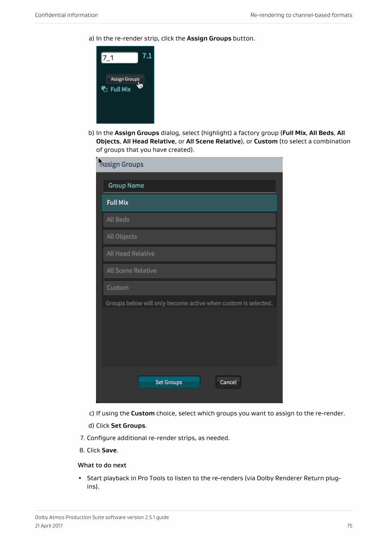
a) In the re-render strip, click the Assign Groups button.
b) In the Assign Groups dialog, select (highlight) a factory group (Full Mix, All Beds, AllObjects, All Head Relative, or All Scene Relative), or Custom (to select a combinationof groups that you have created).
c) If using the Custom choice, select which groups you want to assign to the re-render.
d) Click Set Groups.
7. Configure additional re-render strips, as needed.
8. Click Save.
What to do next
• Start playback in Pro Tools to listen to the re-renders (via Dolby Renderer Return plug-ins).
Confidential information Re-rendering to channel-based formats
Dolby Atmos Production Suite software version 2.5.1 guide
21 April 2017 75
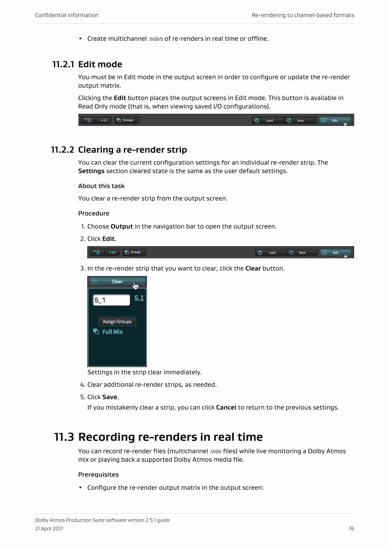
• Create multichannel .wavs of re-renders in real time or offline.
11.2.1 Edit modeYou must be in Edit mode in the output screen in order to configure or update the re-renderoutput matrix.
Clicking the Edit button places the output screens in Edit mode. This button is available inRead Only mode (that is, when viewing saved I/O configurations).
11.2.2 Clearing a re-render stripYou can clear the current configuration settings for an individual re-render strip. TheSettings section cleared state is the same as the user default settings.
About this task
You clear a re-render strip from the output screen.
Procedure
1. Choose Output in the navigation bar to open the output screen.
2. Click Edit.
3. In the re-render strip that you want to clear, click the Clear button.
Settings in the strip clear immediately.
4. Clear additional re-render strips, as needed.
5. Click Save.
If you mistakenly clear a strip, you can click Cancel to return to the previous settings.
11.3 Recording re-renders in real timeYou can record re-render files (multichannel .wav files) while live monitoring a Dolby Atmosmix or playing back a supported Dolby Atmos media file.
Prerequisites
• Configure the re-render output matrix in the output screen:
Confidential information Re-rendering to channel-based formats
Dolby Atmos Production Suite software version 2.5.1 guide
21 April 2017 76
• The width of a strip defines the type of multichannel .wav file that is output.
• The Renderer supports creating up to ten re-renders, because there are ten re-renderstrips.
• Configure Pro Tools for recording re-render outputs: Create and configure the returntracks that route re-render outputs from the Dolby Atmos Renderer, and then bus the re-rendered audio to audio tracks.
About this task
You can create re-renders from an .atmos (or .damf) master file set, as well as a DolbyAtmos .wav ADM BWF file, cinema print master (.rpl) file, encoded .mxf file, or pmstitch .xml file.
Although you can monitor and record re-renders during master recording or master punch inand out recording, we recommend that you disable re-renders during recording to avoid highprocessing loads.
This task does not use Dolby Renderer Send plug-ins. The Pro Tools session for this task doesnot require Dolby Renderer Send plug-ins.
Procedure
1. In the Renderer window, choose Mastering in the navigation bar to open the masteringscreen.
2. Select or type in the path and file name of the Dolby Atmos media file in the Master Filefield.
3. Click Set to load the master:
• By default, the master loads in Read Only mode to prevent accidentally overwritingmaterial.
• The timecode rate shown in the FPS field automatically updates to the mastertimecode rate
• The Master button automatically enables (if it was previously disabled).
4. Ensure that the Master button in the status and control section is enabled.
5. Record ready re-render audio tracks in Pro Tools.
6. In Pro Tools, start playback at or before the master start time (which is shown in the Startdisplay in the Master Playback and Recording Operations section of the masteringscreen).
7. When done, stop playback in Pro Tools.
11.4 Creating re-renders offlineYou can create re-render files (multichannel .wav files) from a supported Dolby Atmos mediafile without having to play back the file. This process is called offline re-rendering.
Prerequisites
• Configure the re-render output matrix in the output screen:
• When doing offline re-rendering, the width of a strip defines the type ofmultichannel .wav that will be created. Additionally, the re-render strip name will beincluded in the name of the .wav file.
• The Renderer supports creating up to ten re-renders since there are ten re-renderstrips.
Confidential information Re-rendering to channel-based formats
Dolby Atmos Production Suite software version 2.5.1 guide
21 April 2017 77
• If doing an offline re-render immediately after recording or punching in and out of amaster recording, and then playing back the master, you must unset and reset the masterprior to doing the offline recording. This restores the offline re-render feature.
About this task
You can create re-renders from an .atmos (or .damf) master file set, as well as aDolby Atmos .wav ADM BWF file, cinema print master (.rpl) file, encoded .mxf file, orpmstitch .xml file.
The Renderer offline re-rendering option creates stereo and B-format re-renders that areinterleaved .wav files. 5.0 and larger re-renders are exported as multiple-mono .wav files. Forthese re-renders, the multiple-mono exports are saved to a folder with the same name asthe file export, and follow standard track numbering and naming conventions.
If doing an offline re-render immediately after recording or punching in and out of a masterrecording, and then playing back the master, you must unset and reset the master prior todoing the offline recording (in order to restore the offline re-render feature.
This task does not use Dolby Renderer Return plug-ins. The Pro Tools session for this taskdoes not require Dolby Renderer Return plug-ins.
Procedure
1. In the Renderer window, choose Mastering in the navigation bar to open the masteringscreen.
2. Select or type in the path and file name of the Dolby Atmos media file in the Master Filefield.
3. Click Set to load the master:
• By default, the master loads in Read Only mode to prevent accidentally overwritingmaterial.
• The timecode rate shown in the FPS field automatically updates to the mastertimecode rate.
• The Master button automatically enables (if it was previously disabled).
4. Ensure that the Master button in the status and control section is enabled.
With a master loaded and the Renderer in master mode, you can perform an offline re-render.
5. In the Offline Re-rendering section, set the time range for the re-renders:
a) Click (set to on) the Set time range option.
b) In the In field, type in the timecode value where the re-renders should start.
c) In the Out field, type in the timecode value where the re-renders should end.
6. In the Re-render file output location field, select or type in the path of the re-renderfiles.
7. Optional: In the Output file basename (optional) field, type in a different default basename for new re-render .wav files.
Confidential information Re-rendering to channel-based formats
Dolby Atmos Production Suite software version 2.5.1 guide
21 April 2017 78
When you create a re-render file, this name is added to the file name, prior to the re-render strip name. For example, if the re-render strip name is 7.1, and you provide a basename of trailer, the re-rendered file will be named trailer_7.1.wav.
8. Click the Start re-rendering button.
ResultsAt the specified re-rendered output location, the Renderer creates .wav files for each re-render strip that has a width.
Confidential information Re-rendering to channel-based formats
Dolby Atmos Production Suite software version 2.5.1 guide
21 April 2017 79
12 Customizing the RendererCustomize your Renderer application to change the room layout and monitoring options, orto apply equalization or level setting for speakers.
• Overview for customizing your Renderer• Editing a custom equalization preset• Editing expert settings in the settings screen
12.1 Overview for customizing your RendererThe Dolby Atmos Renderer application provides controls to customize monitoring andplayback features in your Renderer software.
12.1.1 Selecting an operation modeAfter launching the Renderer, you can choose the operating mode for your content creationworkflow: VR or home theater. Each mode includes features and controls specific to theirworkflow.
About this task
Changing modes replaces your current settings with the default settings for the new mode.
Procedure
1. Choose Maintenance in the navigation bar to open the maintenance screen.
2. In the Mode section, perform one of these steps:
• For VR content creation, click (check) VR.
• For home theater content creation, click (check) Home Theater.
3. For access to the Settings menu and additional Monitoring controls, click Expert.
12.1.2 Setting up the physical layout for your roomThe Dolby Atmos Renderer provides a default physical layout of a typical reference DolbyAtmos home theater listening room and its 7.1 ear-level speakers and four overheadspeakers.
About this task
Before you begin working on production of Dolby Atmos material, ensure that the renderingand mastering software is properly set up to match the physical layout of your room and itsspeakers. Typically, you will need to do this only once for a given room.
Procedure
1. Choose Room in the navigation bar to display the room screen.
Confidential information Customizing the Renderer
Dolby Atmos Production Suite software version 2.5.1 guide
21 April 2017 80
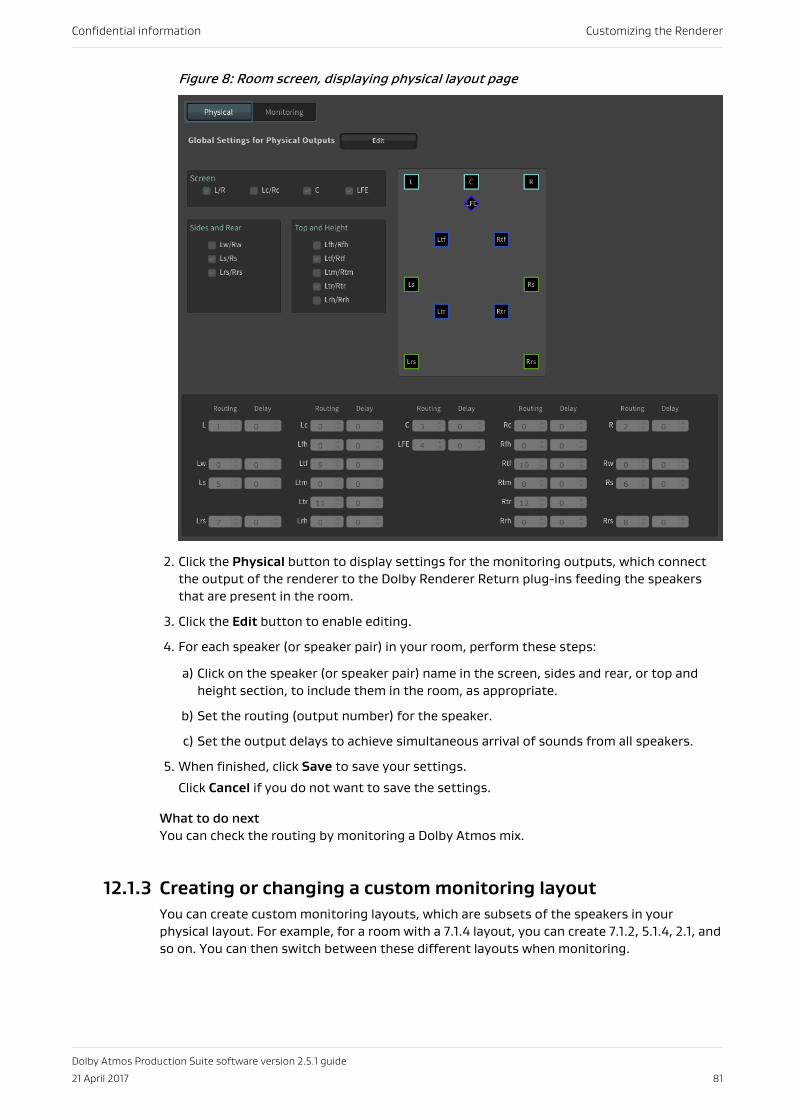
Figure 8: Room screen, displaying physical layout page
2. Click the Physical button to display settings for the monitoring outputs, which connectthe output of the renderer to the Dolby Renderer Return plug-ins feeding the speakersthat are present in the room.
3. Click the Edit button to enable editing.
4. For each speaker (or speaker pair) in your room, perform these steps:
a) Click on the speaker (or speaker pair) name in the screen, sides and rear, or top andheight section, to include them in the room, as appropriate.
b) Set the routing (output number) for the speaker.
c) Set the output delays to achieve simultaneous arrival of sounds from all speakers.
5. When finished, click Save to save your settings.
Click Cancel if you do not want to save the settings.
What to do nextYou can check the routing by monitoring a Dolby Atmos mix.
12.1.3 Creating or changing a custom monitoring layoutYou can create custom monitoring layouts, which are subsets of the speakers in yourphysical layout. For example, for a room with a 7.1.4 layout, you can create 7.1.2, 5.1.4, 2.1, andso on. You can then switch between these different layouts when monitoring.
Confidential information Customizing the Renderer
Dolby Atmos Production Suite software version 2.5.1 guide
21 April 2017 81
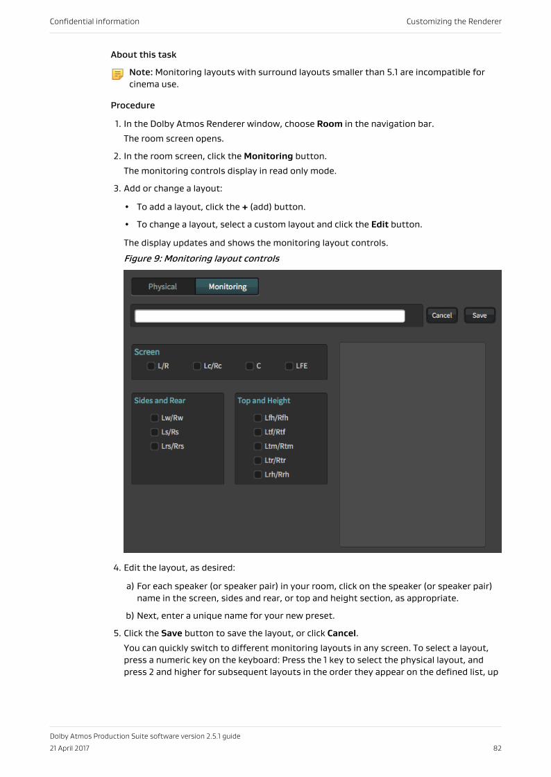
About this task
Note: Monitoring layouts with surround layouts smaller than 5.1 are incompatible forcinema use.
Procedure
1. In the Dolby Atmos Renderer window, choose Room in the navigation bar.
The room screen opens.
2. In the room screen, click the Monitoring button.
The monitoring controls display in read only mode.
3. Add or change a layout:
• To add a layout, click the + (add) button.
• To change a layout, select a custom layout and click the Edit button.
The display updates and shows the monitoring layout controls.
Figure 9: Monitoring layout controls
4. Edit the layout, as desired:
a) For each speaker (or speaker pair) in your room, click on the speaker (or speaker pair)name in the screen, sides and rear, or top and height section, as appropriate.
b) Next, enter a unique name for your new preset.
5. Click the Save button to save the layout, or click Cancel.
You can quickly switch to different monitoring layouts in any screen. To select a layout,press a numeric key on the keyboard: Press the 1 key to select the physical layout, andpress 2 and higher for subsequent layouts in the order they appear on the defined list, up
Confidential information Customizing the Renderer
Dolby Atmos Production Suite software version 2.5.1 guide
21 April 2017 82
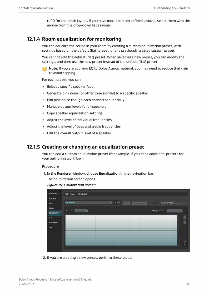
to 10 for the tenth layout. If you have more than ten defined layouts, select them with themouse from the drop-down list as usual.
12.1.4 Room equalization for monitoringYou can equalize the sound in your room by creating a custom equalization preset, withsettings based on the default (flat) preset, or any previously created custom preset.
You cannot edit the default (flat) preset. When saved as a new preset, you can modify thesettings, and then use the new preset instead of the default (flat) preset.
Note: If you are applying EQ to Dolby Atmos material, you may need to reduce that gainto avoid cilpping.
For each preset, you can:
• Select a specific speaker feed
• Generate pink noise (or other tone signals) to a specific speaker
• Pan pink noise though each channel sequentially
• Manage output levels for all speakers
• Copy speaker equalization settings
• Adjust the level of individual frequencies
• Adjust the level of bass and treble frequencies
• Edit the overall output level of a speaker
12.1.5 Creating or changing an equalization presetYou can add a custom equalization preset (for example, if you need additional presets foryour authoring workflow).
Procedure
1. In the Renderer window, choose Equalization in the navigation bar.
The equalization screen opens.
Figure 10: Equalization screen
2. If you are creating a new preset, perform these steps:
Confidential information Customizing the Renderer
Dolby Atmos Production Suite software version 2.5.1 guide
21 April 2017 83
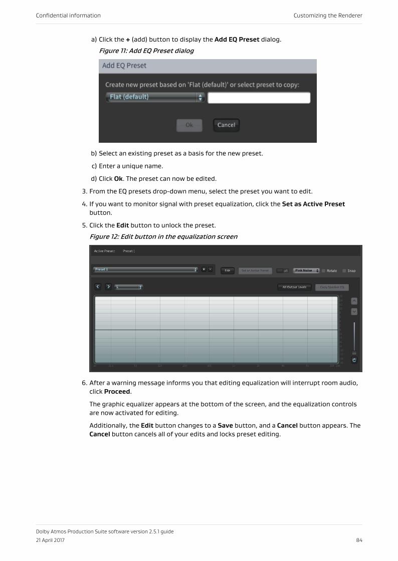
a) Click the + (add) button to display the Add EQ Preset dialog.
Figure 11: Add EQ Preset dialog
b) Select an existing preset as a basis for the new preset.
c) Enter a unique name.
d) Click Ok. The preset can now be edited.
3. From the EQ presets drop-down menu, select the preset you want to edit.
4. If you want to monitor signal with preset equalization, click the Set as Active Presetbutton.
5. Click the Edit button to unlock the preset.
Figure 12: Edit button in the equalization screen
6. After a warning message informs you that editing equalization will interrupt room audio,click Proceed.
The graphic equalizer appears at the bottom of the screen, and the equalization controlsare now activated for editing.
Additionally, the Edit button changes to a Save button, and a Cancel button appears. TheCancel button cancels all of your edits and locks preset editing.
Confidential information Customizing the Renderer
Dolby Atmos Production Suite software version 2.5.1 guide
21 April 2017 84
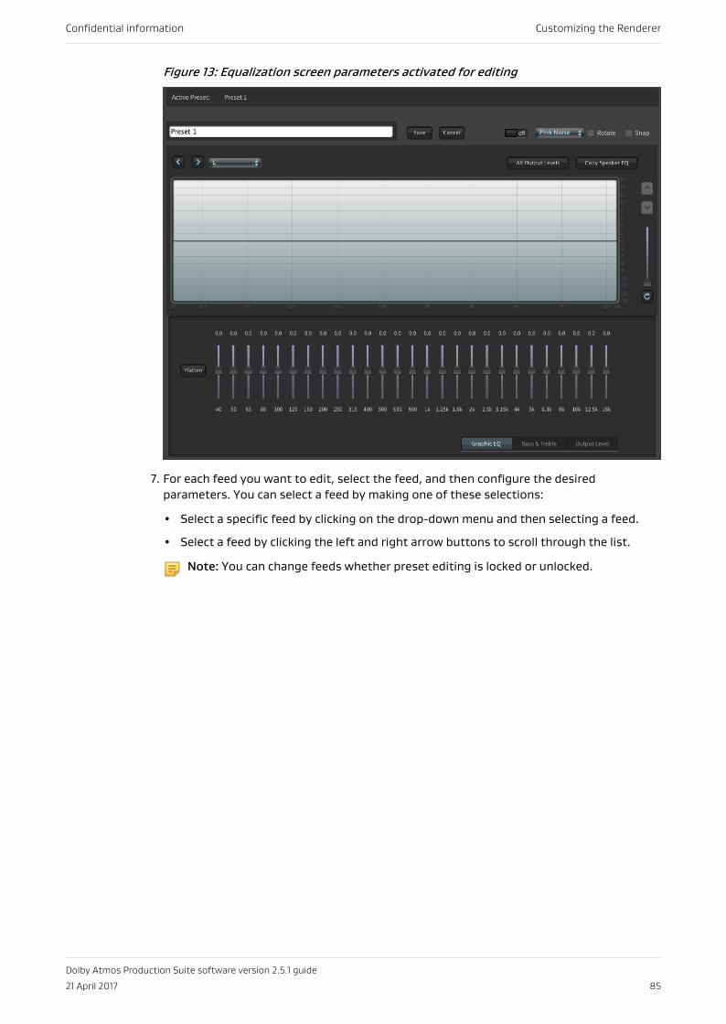
Figure 13: Equalization screen parameters activated for editing
7. For each feed you want to edit, select the feed, and then configure the desiredparameters. You can select a feed by making one of these selections:
• Select a specific feed by clicking on the drop-down menu and then selecting a feed.
• Select a feed by clicking the left and right arrow buttons to scroll through the list.
Note: You can change feeds whether preset editing is locked or unlocked.
Confidential information Customizing the Renderer
Dolby Atmos Production Suite software version 2.5.1 guide
21 April 2017 85

Figure 14: Speaker feeds in the equalization screen
8. Click the Save button to save the preset, or click Cancel.
9. When prompted by the Confirm dialog, click the Ok button.
12.2 Editing a custom equalization presetYou can use the options in the equalization screen to edit custom equalization presets.
Confidential information Customizing the Renderer
Dolby Atmos Production Suite software version 2.5.1 guide
21 April 2017 86
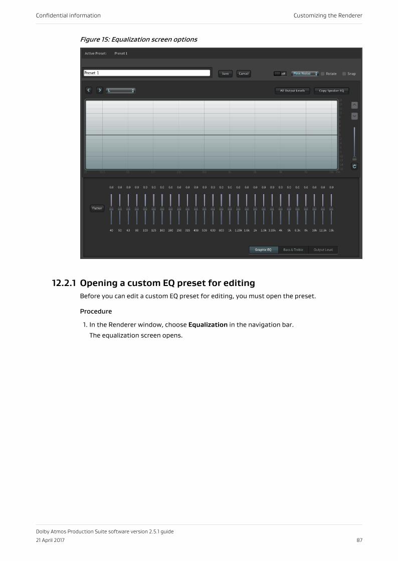
Figure 15: Equalization screen options
12.2.1 Opening a custom EQ preset for editingBefore you can edit a custom EQ preset for editing, you must open the preset.
Procedure
1. In the Renderer window, choose Equalization in the navigation bar.
The equalization screen opens.
Confidential information Customizing the Renderer
Dolby Atmos Production Suite software version 2.5.1 guide
21 April 2017 87
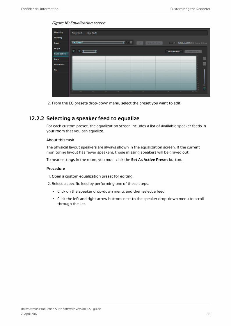
Figure 16: Equalization screen
2. From the EQ presets drop-down menu, select the preset you want to edit.
12.2.2 Selecting a speaker feed to equalizeFor each custom preset, the equalization screen includes a list of available speaker feeds inyour room that you can equalize.
About this task
The physical layout speakers are always shown in the equalization screen. If the currentmonitoring layout has fewer speakers, those missing speakers will be grayed out.
To hear settings in the room, you must click the Set As Active Preset button.
Procedure
1. Open a custom equalization preset for editing.
2. Select a specific feed by performing one of these steps:
• Click on the speaker drop-down menu, and then select a feed.
• Click the left and right arrow buttons next to the speaker drop-down menu to scrollthrough the list.
Confidential information Customizing the Renderer
Dolby Atmos Production Suite software version 2.5.1 guide
21 April 2017 88
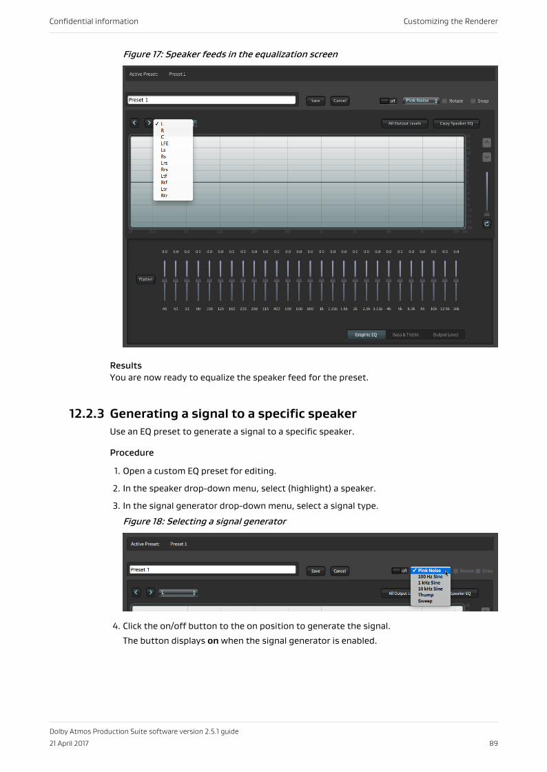
Figure 17: Speaker feeds in the equalization screen
ResultsYou are now ready to equalize the speaker feed for the preset.
12.2.3 Generating a signal to a specific speakerUse an EQ preset to generate a signal to a specific speaker.
Procedure
1. Open a custom EQ preset for editing.
2. In the speaker drop-down menu, select (highlight) a speaker.
3. In the signal generator drop-down menu, select a signal type.
Figure 18: Selecting a signal generator
4. Click the on/off button to the on position to generate the signal.
The button displays on when the signal generator is enabled.
Confidential information Customizing the Renderer
Dolby Atmos Production Suite software version 2.5.1 guide
21 April 2017 89
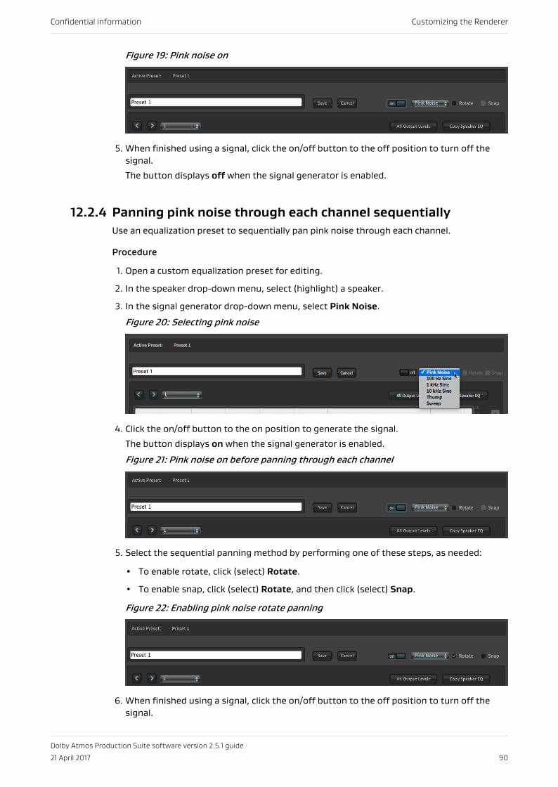
Figure 19: Pink noise on
5. When finished using a signal, click the on/off button to the off position to turn off thesignal.
The button displays off when the signal generator is enabled.
12.2.4 Panning pink noise through each channel sequentiallyUse an equalization preset to sequentially pan pink noise through each channel.
Procedure
1. Open a custom equalization preset for editing.
2. In the speaker drop-down menu, select (highlight) a speaker.
3. In the signal generator drop-down menu, select Pink Noise.
Figure 20: Selecting pink noise
4. Click the on/off button to the on position to generate the signal.
The button displays on when the signal generator is enabled.
Figure 21: Pink noise on before panning through each channel
5. Select the sequential panning method by performing one of these steps, as needed:
• To enable rotate, click (select) Rotate.
• To enable snap, click (select) Rotate, and then click (select) Snap.
Figure 22: Enabling pink noise rotate panning
6. When finished using a signal, click the on/off button to the off position to turn off thesignal.
Confidential information Customizing the Renderer
Dolby Atmos Production Suite software version 2.5.1 guide
21 April 2017 90
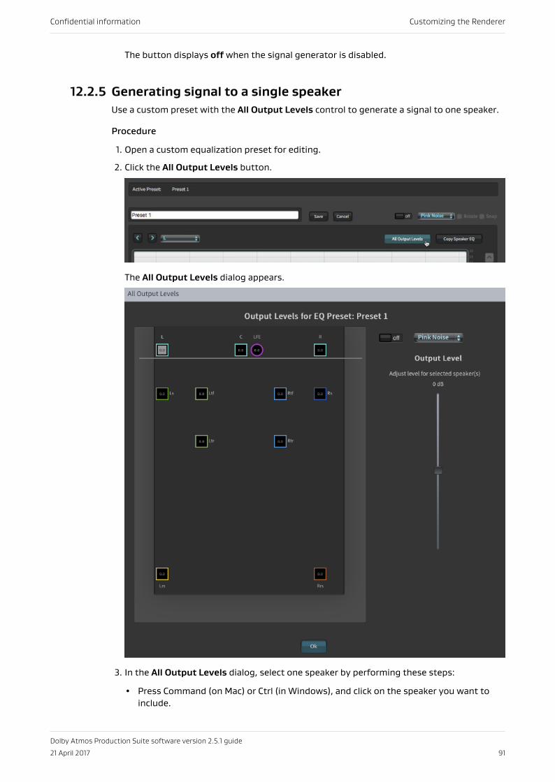
The button displays off when the signal generator is disabled.
12.2.5 Generating signal to a single speakerUse a custom preset with the All Output Levels control to generate a signal to one speaker.
Procedure
1. Open a custom equalization preset for editing.
2. Click the All Output Levels button.
The All Output Levels dialog appears.
3. In the All Output Levels dialog, select one speaker by performing these steps:
• Press Command (on Mac) or Ctrl (in Windows), and click on the speaker you want toinclude.
Confidential information Customizing the Renderer
Dolby Atmos Production Suite software version 2.5.1 guide
21 April 2017 91
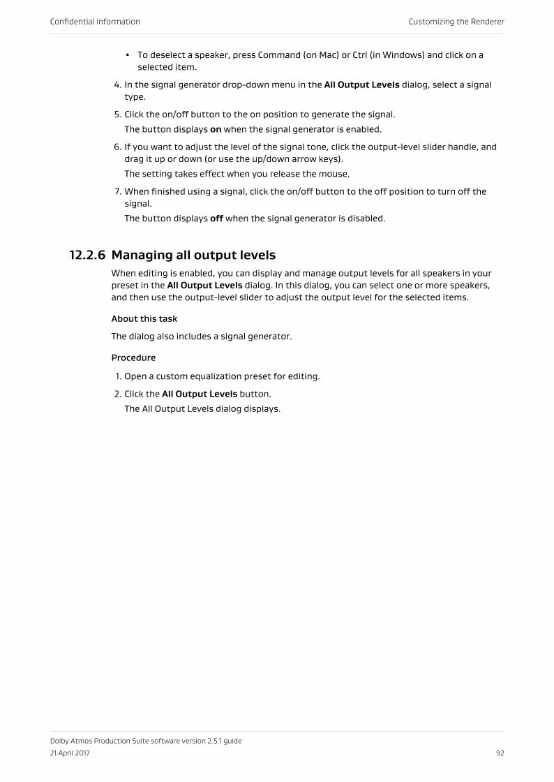
• To deselect a speaker, press Command (on Mac) or Ctrl (in Windows) and click on aselected item.
4. In the signal generator drop-down menu in the All Output Levels dialog, select a signaltype.
5. Click the on/off button to the on position to generate the signal.
The button displays on when the signal generator is enabled.
6. If you want to adjust the level of the signal tone, click the output-level slider handle, anddrag it up or down (or use the up/down arrow keys).
The setting takes effect when you release the mouse.
7. When finished using a signal, click the on/off button to the off position to turn off thesignal.
The button displays off when the signal generator is disabled.
12.2.6 Managing all output levelsWhen editing is enabled, you can display and manage output levels for all speakers in yourpreset in the All Output Levels dialog. In this dialog, you can select one or more speakers,and then use the output-level slider to adjust the output level for the selected items.
About this task
The dialog also includes a signal generator.
Procedure
1. Open a custom equalization preset for editing.
2. Click the All Output Levels button.
The All Output Levels dialog displays.
Confidential information Customizing the Renderer
Dolby Atmos Production Suite software version 2.5.1 guide
21 April 2017 92
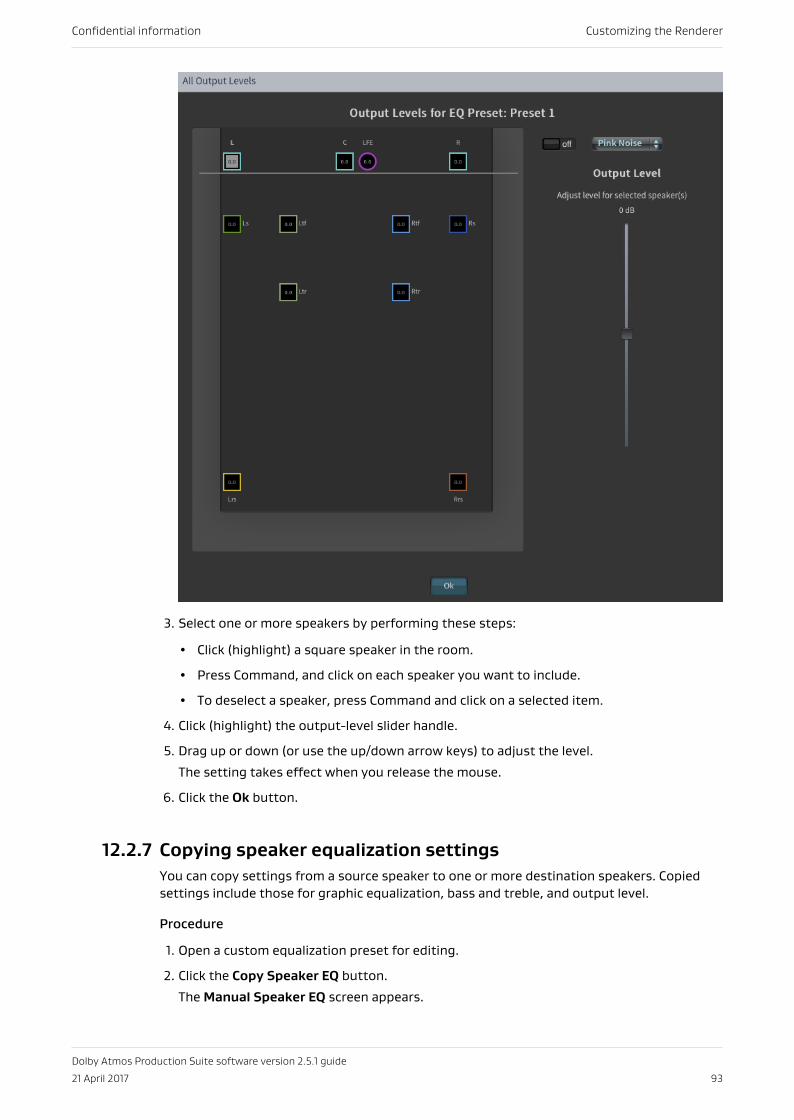
3. Select one or more speakers by performing these steps:
• Click (highlight) a square speaker in the room.
• Press Command, and click on each speaker you want to include.
• To deselect a speaker, press Command and click on a selected item.
4. Click (highlight) the output-level slider handle.
5. Drag up or down (or use the up/down arrow keys) to adjust the level.
The setting takes effect when you release the mouse.
6. Click the Ok button.
12.2.7 Copying speaker equalization settingsYou can copy settings from a source speaker to one or more destination speakers. Copiedsettings include those for graphic equalization, bass and treble, and output level.
Procedure
1. Open a custom equalization preset for editing.
2. Click the Copy Speaker EQ button.
The Manual Speaker EQ screen appears.
Confidential information Customizing the Renderer
Dolby Atmos Production Suite software version 2.5.1 guide
21 April 2017 93
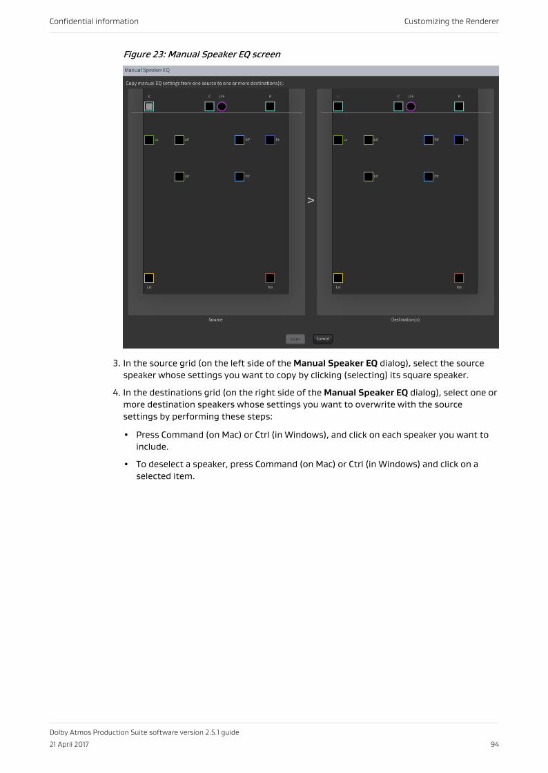
Figure 23: Manual Speaker EQ screen
3. In the source grid (on the left side of the Manual Speaker EQ dialog), select the sourcespeaker whose settings you want to copy by clicking (selecting) its square speaker.
4. In the destinations grid (on the right side of the Manual Speaker EQ dialog), select one ormore destination speakers whose settings you want to overwrite with the sourcesettings by performing these steps:
• Press Command (on Mac) or Ctrl (in Windows), and click on each speaker you want toinclude.
• To deselect a speaker, press Command (on Mac) or Ctrl (in Windows) and click on aselected item.
Confidential information Customizing the Renderer
Dolby Atmos Production Suite software version 2.5.1 guide
21 April 2017 94
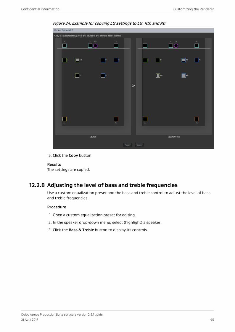
Figure 24: Example for copying Ltf settings to Ltr, Rtf, and Rtr
5. Click the Copy button.
ResultsThe settings are copied.
12.2.8 Adjusting the level of bass and treble frequenciesUse a custom equalization preset and the bass and treble control to adjust the level of bassand treble frequencies.
Procedure
1. Open a custom equalization preset for editing.
2. In the speaker drop-down menu, select (highlight) a speaker.
3. Click the Bass & Treble button to display its controls.
Confidential information Customizing the Renderer
Dolby Atmos Production Suite software version 2.5.1 guide
21 April 2017 95
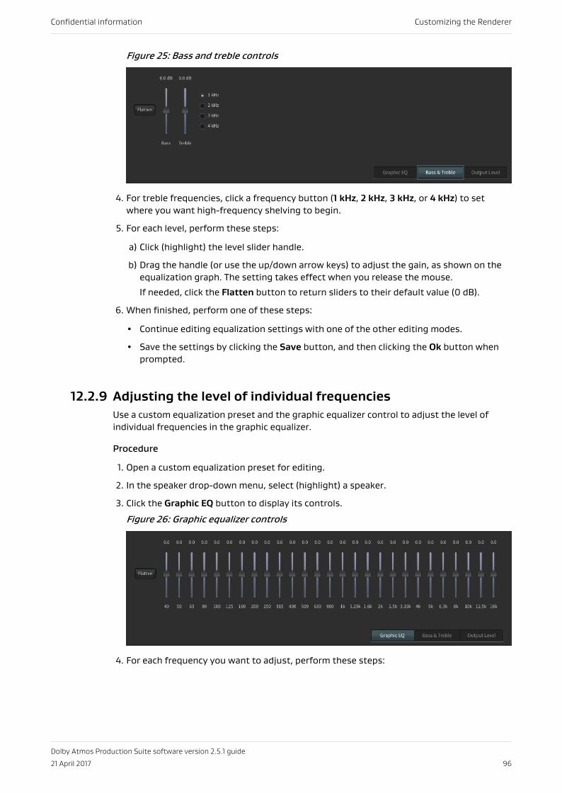
Figure 25: Bass and treble controls
4. For treble frequencies, click a frequency button (1 kHz, 2 kHz, 3 kHz, or 4 kHz) to setwhere you want high-frequency shelving to begin.
5. For each level, perform these steps:
a) Click (highlight) the level slider handle.
b) Drag the handle (or use the up/down arrow keys) to adjust the gain, as shown on theequalization graph. The setting takes effect when you release the mouse.
If needed, click the Flatten button to return sliders to their default value (0 dB).
6. When finished, perform one of these steps:
• Continue editing equalization settings with one of the other editing modes.
• Save the settings by clicking the Save button, and then clicking the Ok button whenprompted.
12.2.9 Adjusting the level of individual frequenciesUse a custom equalization preset and the graphic equalizer control to adjust the level ofindividual frequencies in the graphic equalizer.
Procedure
1. Open a custom equalization preset for editing.
2. In the speaker drop-down menu, select (highlight) a speaker.
3. Click the Graphic EQ button to display its controls.
Figure 26: Graphic equalizer controls
4. For each frequency you want to adjust, perform these steps:
Confidential information Customizing the Renderer
Dolby Atmos Production Suite software version 2.5.1 guide
21 April 2017 96
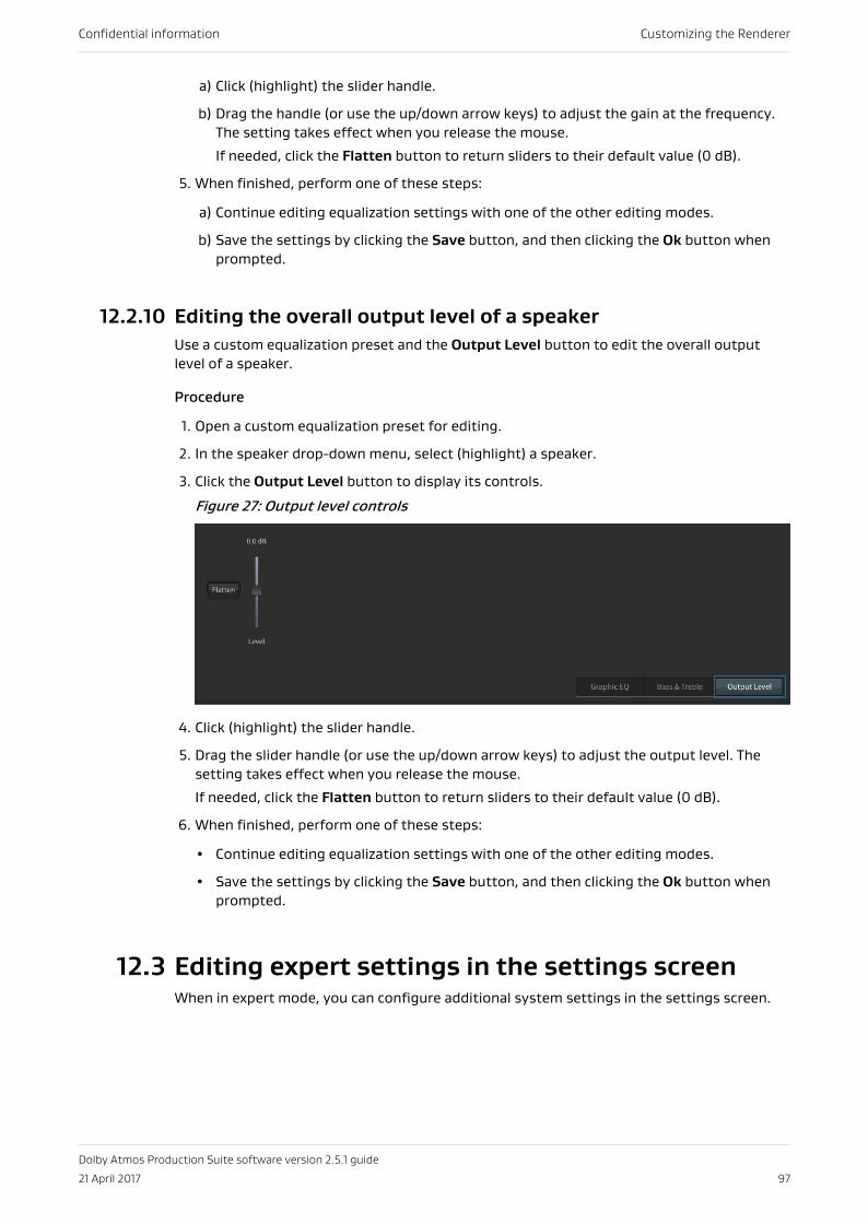
a) Click (highlight) the slider handle.
b) Drag the handle (or use the up/down arrow keys) to adjust the gain at the frequency.The setting takes effect when you release the mouse.
If needed, click the Flatten button to return sliders to their default value (0 dB).
5. When finished, perform one of these steps:
a) Continue editing equalization settings with one of the other editing modes.
b) Save the settings by clicking the Save button, and then clicking the Ok button whenprompted.
12.2.10 Editing the overall output level of a speakerUse a custom equalization preset and the Output Level button to edit the overall outputlevel of a speaker.
Procedure
1. Open a custom equalization preset for editing.
2. In the speaker drop-down menu, select (highlight) a speaker.
3. Click the Output Level button to display its controls.
Figure 27: Output level controls
4. Click (highlight) the slider handle.
5. Drag the slider handle (or use the up/down arrow keys) to adjust the output level. Thesetting takes effect when you release the mouse.
If needed, click the Flatten button to return sliders to their default value (0 dB).
6. When finished, perform one of these steps:
• Continue editing equalization settings with one of the other editing modes.
• Save the settings by clicking the Save button, and then clicking the Ok button whenprompted.
12.3 Editing expert settings in the settings screenWhen in expert mode, you can configure additional system settings in the settings screen.
Confidential information Customizing the Renderer
Dolby Atmos Production Suite software version 2.5.1 guide
21 April 2017 97
12.3.1 Adjusting the speakers pre-EQ gain (dB) for headroomoptimizationYou can globally adjust the gain of the Renderer (before the Renderer applicationequalization settings and the Monitor application attenuation control). The default gain is 10dB. The range is -60 to 10 dB.
PrerequisitesEnsure that expert mode is enabled in the maintenance screen. This gain control is availablein expert mode only.
Note: If you are applying EQ to Dolby Atmos material, you may need to reduce that gainto avoid clipping.
Procedure
1. Choose Settings in the navigation bar to open the settings screen.
2. In the settings screen, adjust the setting for Speakers Pre-EQ Gain (dB) for HeadroomOptimization.
Make changes immediately with the up/down arrow keys, or type in a value, and thenpress the Enter key.
12.3.2 Setting the global audio delay (ms)The Dolby Atmos Renderer includes a control for globally setting audio delay.
About this task
Typically, no additional global audio delay is needed. However, if there is significant videosignal path delay, use this setting to align audio and video. The default is 0 ms. The range is0–200 ms.
Procedure
1. Choose Settings in the navigation bar to open the settings screen.
2. In the settings screen, adjust the setting for Global Audio Delay (ms).
Make changes immediately with the up/down arrow keys, or type in a value, and thenpress the Enter key.
Confidential information Customizing the Renderer
Dolby Atmos Production Suite software version 2.5.1 guide
21 April 2017 98
13 Configuring your inputsConfigure your inputs to specify the type of input, label the inputs, and assign inputs togroups for monitoring and recording (for example, to configure the Renderer for multiplebeds).
• Editing and saving input routing and group assignments• Multiple beds
13.1 Editing and saving input routing and groupassignmentsYou can edit and save an input configuration. This lets you configure input channels as bedsor objects, name the beds and objects, and then assign inputs to groups for live monitoringor channel-based recording of your Dolby Atmos mix. The input configuration is also saved inthe .atmos master file during recording.
Prerequisites
1. Configure your Dolby Atmos session in Pro Tools with beds, objects, and a supporting I/Osetup, as desired. Include stems that you intend to configure as beds or groups of beds orobjects.
Alternatively, you can configure your inputs first, and then update your Dolby Atmossession.
2. Make sure that no master is set (loaded and initialized).
3. Review custom groups if you want to monitor re-renders with custom groups.
4. Make sure that you have created custom groups that refer logically to channel groups inyour Dolby Atmos session in Pro Tools. For example, for a percussion music stem, youcould have a group labeled percussion in the Groups dialog.
Note: You can edit multiple items in a column by performing one of these steps:
• To select multiple contiguous items, Shift-click on the first and last item in a range tohighlight the entire range of items, and then make a selection.
• To select multiple noncontiguous items, Command-click on each item, and then makea selection.
Procedure
1. Choose Input in the navigation bar to open the input screen.
2. Click Edit.
3. In the Assignment column, configure input channels as beds, objects, or unassigned(based on their use in the Dolby Atmos session in Pro Tools):
Confidential information Configuring your inputs
Dolby Atmos Production Suite software version 2.5.1 guide
21 April 2017 99
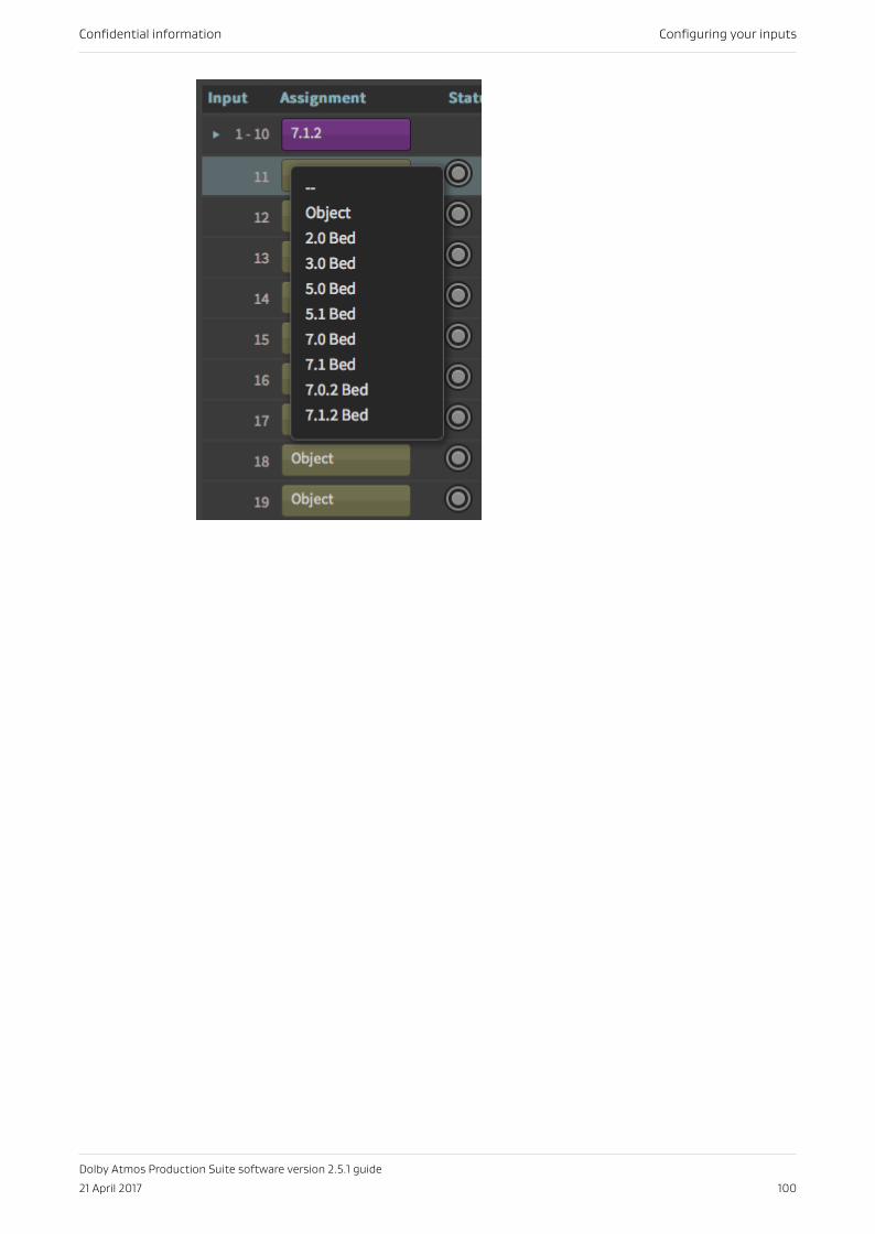
Confidential information Configuring your inputs
Dolby Atmos Production Suite software version 2.5.1 guide
21 April 2017 100
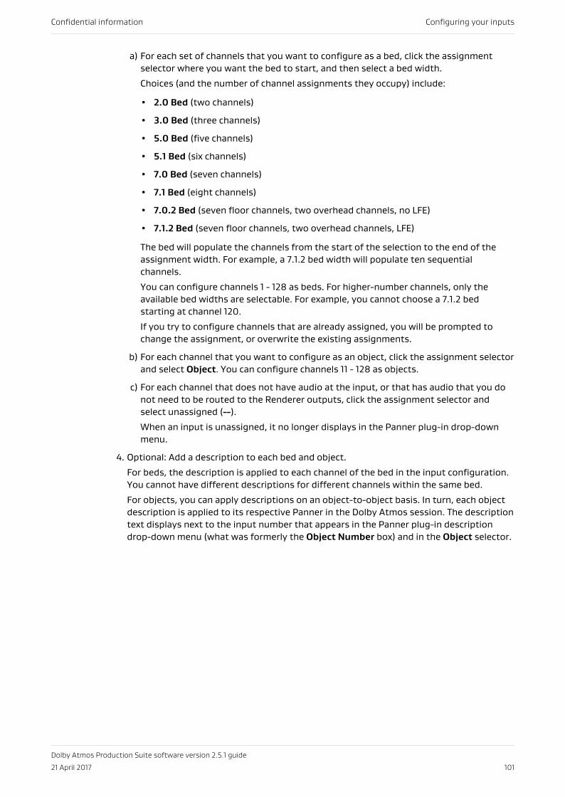
a) For each set of channels that you want to configure as a bed, click the assignmentselector where you want the bed to start, and then select a bed width.
Choices (and the number of channel assignments they occupy) include:
• 2.0 Bed (two channels)
• 3.0 Bed (three channels)
• 5.0 Bed (five channels)
• 5.1 Bed (six channels)
• 7.0 Bed (seven channels)
• 7.1 Bed (eight channels)
• 7.0.2 Bed (seven floor channels, two overhead channels, no LFE)
• 7.1.2 Bed (seven floor channels, two overhead channels, LFE)
The bed will populate the channels from the start of the selection to the end of theassignment width. For example, a 7.1.2 bed width will populate ten sequentialchannels.
You can configure channels 1 - 128 as beds. For higher-number channels, only theavailable bed widths are selectable. For example, you cannot choose a 7.1.2 bedstarting at channel 120.
If you try to configure channels that are already assigned, you will be prompted tochange the assignment, or overwrite the existing assignments.
b) For each channel that you want to configure as an object, click the assignment selectorand select Object. You can configure channels 11 - 128 as objects.
c) For each channel that does not have audio at the input, or that has audio that you donot need to be routed to the Renderer outputs, click the assignment selector andselect unassigned (--).
When an input is unassigned, it no longer displays in the Panner plug-in drop-downmenu.
4. Optional: Add a description to each bed and object.
For beds, the description is applied to each channel of the bed in the input configuration.You cannot have different descriptions for different channels within the same bed.
For objects, you can apply descriptions on an object-to-object basis. In turn, each objectdescription is applied to its respective Panner in the Dolby Atmos session. The descriptiontext displays next to the input number that appears in the Panner plug-in descriptiondrop-down menu (what was formerly the Object Number box) and in the Object selector.
Confidential information Configuring your inputs
Dolby Atmos Production Suite software version 2.5.1 guide
21 April 2017 101
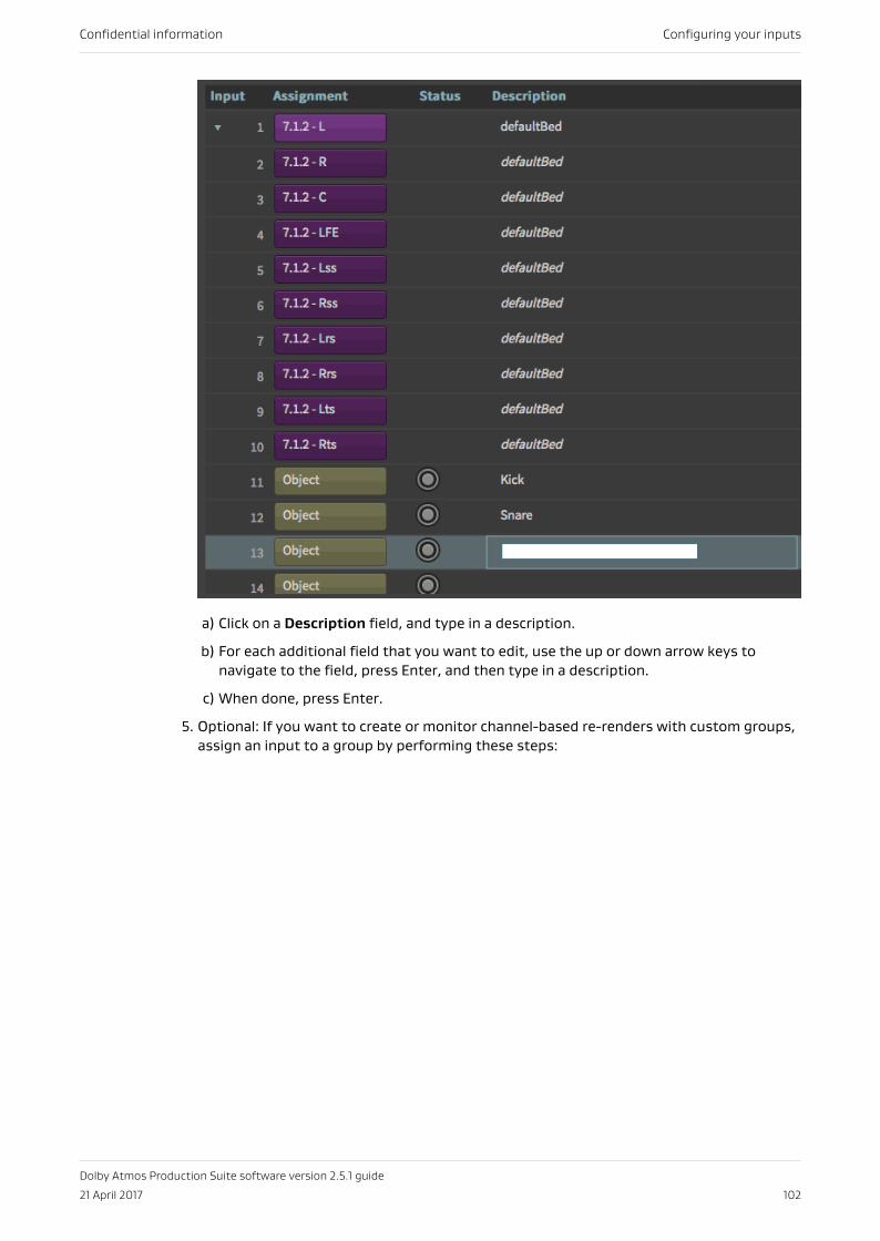
a) Click on a Description field, and type in a description.
b) For each additional field that you want to edit, use the up or down arrow keys tonavigate to the field, press Enter, and then type in a description.
c) When done, press Enter.
5. Optional: If you want to create or monitor channel-based re-renders with custom groups,assign an input to a group by performing these steps:
Confidential information Configuring your inputs
Dolby Atmos Production Suite software version 2.5.1 guide
21 April 2017 102
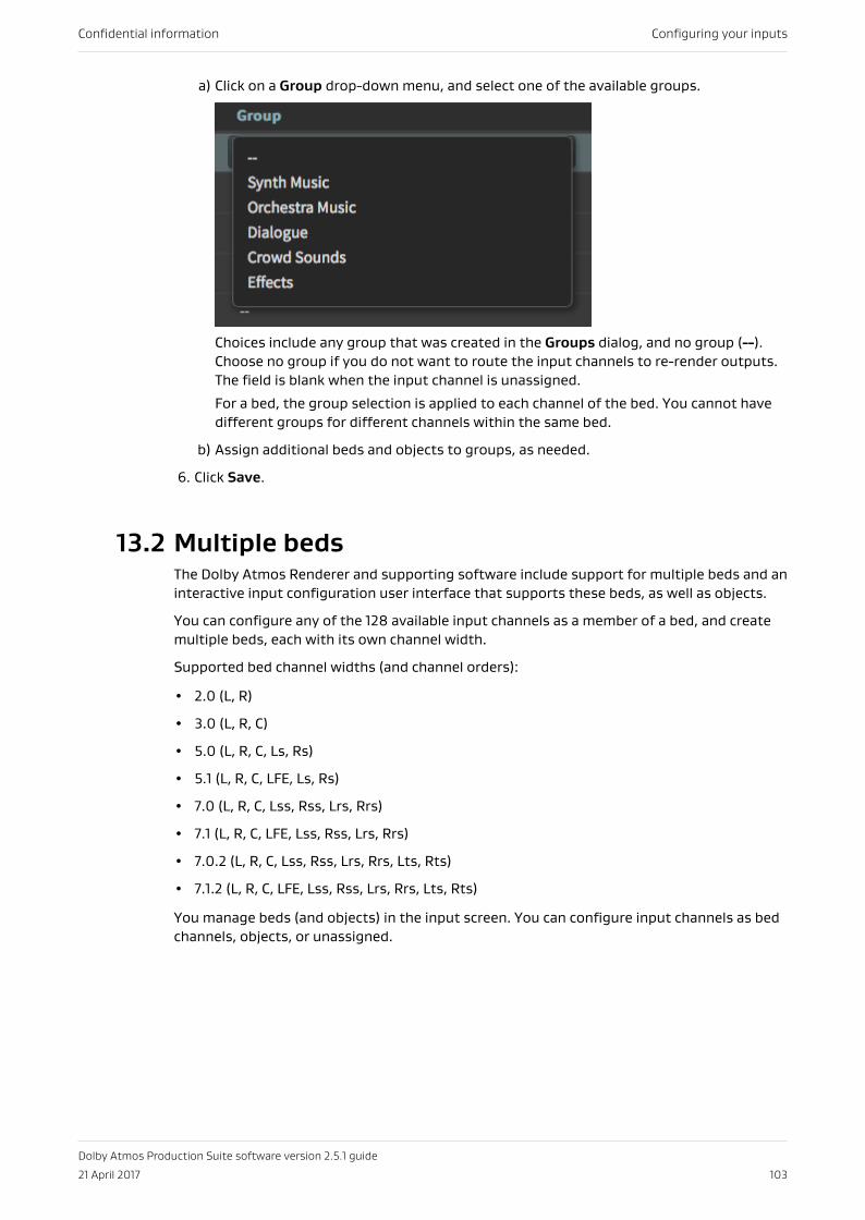
a) Click on a Group drop-down menu, and select one of the available groups.
Choices include any group that was created in the Groups dialog, and no group (--).Choose no group if you do not want to route the input channels to re-render outputs.The field is blank when the input channel is unassigned.
For a bed, the group selection is applied to each channel of the bed. You cannot havedifferent groups for different channels within the same bed.
b) Assign additional beds and objects to groups, as needed.
6. Click Save.
13.2 Multiple bedsThe Dolby Atmos Renderer and supporting software include support for multiple beds and aninteractive input configuration user interface that supports these beds, as well as objects.
You can configure any of the 128 available input channels as a member of a bed, and createmultiple beds, each with its own channel width.
Supported bed channel widths (and channel orders):
• 2.0 (L, R)
• 3.0 (L, R, C)
• 5.0 (L, R, C, Ls, Rs)
• 5.1 (L, R, C, LFE, Ls, Rs)
• 7.0 (L, R, C, Lss, Rss, Lrs, Rrs)
• 7.1 (L, R, C, LFE, Lss, Rss, Lrs, Rrs)
• 7.0.2 (L, R, C, Lss, Rss, Lrs, Rrs, Lts, Rts)
• 7.1.2 (L, R, C, LFE, Lss, Rss, Lrs, Rrs, Lts, Rts)
You manage beds (and objects) in the input screen. You can configure input channels as bedchannels, objects, or unassigned.
Confidential information Configuring your inputs
Dolby Atmos Production Suite software version 2.5.1 guide
21 April 2017 103
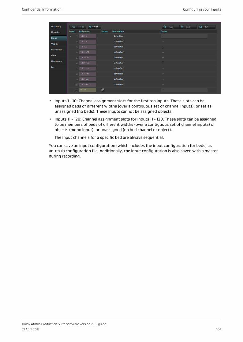
• Inputs 1 - 10: Channel assignment slots for the first ten inputs. These slots can beassigned beds of different widths (over a contiguous set of channel inputs), or set asunassigned (no beds). These inputs cannot be assigned objects.
• Inputs 11 - 128: Channel assignment slots for inputs 11 - 128. These slots can be assignedto be members of beds of different widths (over a contiguous set of channel inputs) orobjects (mono input), or unassigned (no bed channel or object).
The input channels for a specific bed are always sequential.
You can save an input configuration (which includes the input configuration for beds) asan .rmuio configuration file. Additionally, the input configuration is also saved with a masterduring recording.
Confidential information Configuring your inputs
Dolby Atmos Production Suite software version 2.5.1 guide
21 April 2017 104
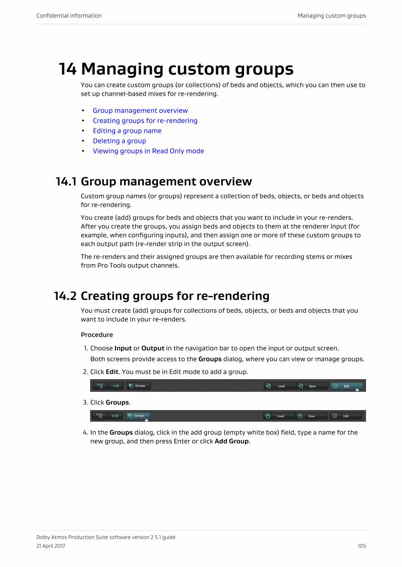
14 Managing custom groupsYou can create custom groups (or collections) of beds and objects, which you can then use toset up channel-based mixes for re-rendering.
• Group management overview• Creating groups for re-rendering• Editing a group name• Deleting a group• Viewing groups in Read Only mode
14.1 Group management overviewCustom group names (or groups) represent a collection of beds, objects, or beds and objectsfor re-rendering.
You create (add) groups for beds and objects that you want to include in your re-renders.After you create the groups, you assign beds and objects to them at the renderer input (forexample, when configuring inputs), and then assign one or more of these custom groups toeach output path (re-render strip in the output screen).
The re-renders and their assigned groups are then available for recording stems or mixesfrom Pro Tools output channels.
14.2 Creating groups for re-renderingYou must create (add) groups for collections of beds, objects, or beds and objects that youwant to include in your re-renders.
Procedure
1. Choose Input or Output in the navigation bar to open the input or output screen.
Both screens provide access to the Groups dialog, where you can view or manage groups.
2. Click Edit. You must be in Edit mode to add a group.
3. Click Groups.
4. In the Groups dialog, click in the add group (empty white box) field, type a name for thenew group, and then press Enter or click Add Group.
Confidential information Managing custom groups
Dolby Atmos Production Suite software version 2.5.1 guide
21 April 2017 105
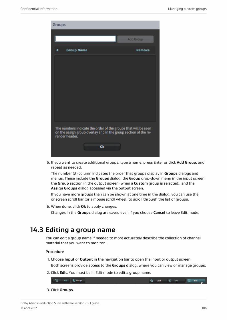
5. If you want to create additional groups, type a name, press Enter or click Add Group, andrepeat as needed.
The number (#) column indicates the order that groups display in Groups dialogs andmenus. These include the Groups dialog, the Group drop-down menu in the input screen,the Group section in the output screen (when a Custom group is selected), and theAssign Groups dialog accessed via the output screen.
If you have more groups than can be shown at one time in the dialog, you can use theonscreen scroll bar (or a mouse scroll wheel) to scroll through the list of groups.
6. When done, click Ok to apply changes.
Changes in the Groups dialog are saved even if you choose Cancel to leave Edit mode.
14.3 Editing a group nameYou can edit a group name if needed to more accurately describe the collection of channelmaterial that you want to monitor.
Procedure
1. Choose Input or Output in the navigation bar to open the input or output screen.
Both screens provide access to the Groups dialog, where you can view or manage groups.
2. Click Edit. You must be in Edit mode to edit a group name.
3. Click Groups.
Confidential information Managing custom groups
Dolby Atmos Production Suite software version 2.5.1 guide
21 April 2017 106
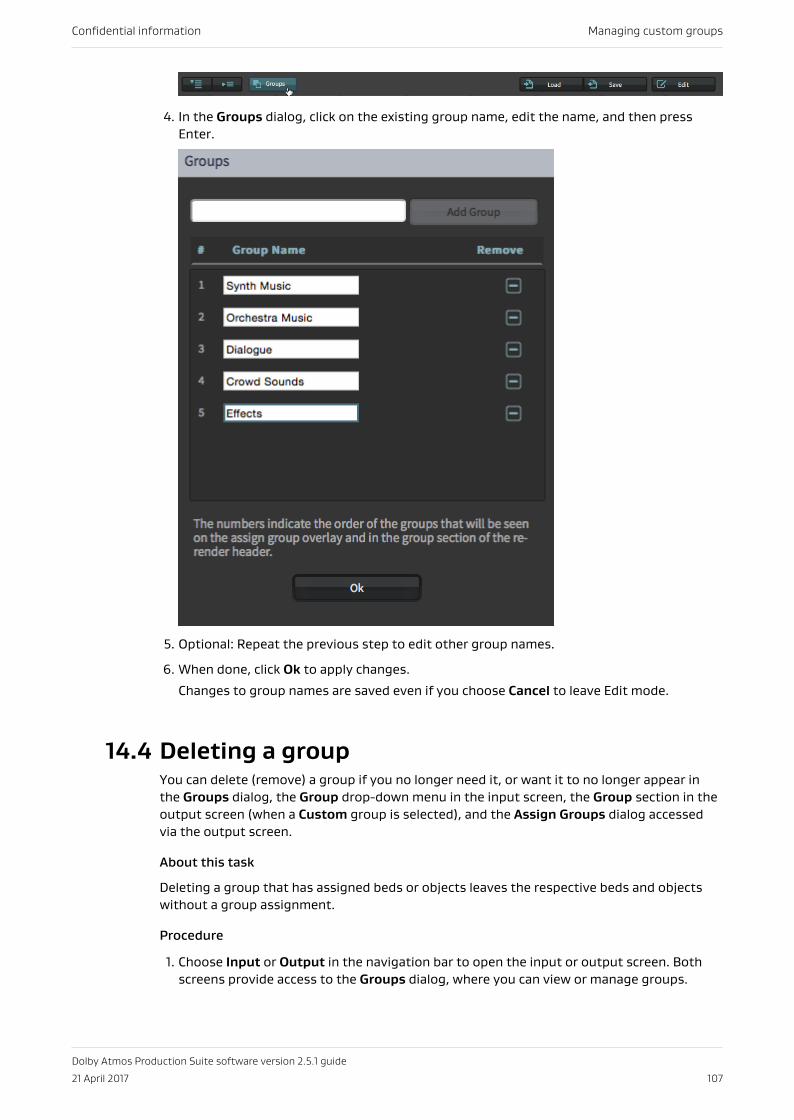
4. In the Groups dialog, click on the existing group name, edit the name, and then pressEnter.
5. Optional: Repeat the previous step to edit other group names.
6. When done, click Ok to apply changes.
Changes to group names are saved even if you choose Cancel to leave Edit mode.
14.4 Deleting a groupYou can delete (remove) a group if you no longer need it, or want it to no longer appear inthe Groups dialog, the Group drop-down menu in the input screen, the Group section in theoutput screen (when a Custom group is selected), and the Assign Groups dialog accessedvia the output screen.
About this task
Deleting a group that has assigned beds or objects leaves the respective beds and objectswithout a group assignment.
Procedure
1. Choose Input or Output in the navigation bar to open the input or output screen. Bothscreens provide access to the Groups dialog, where you can view or manage groups.
Confidential information Managing custom groups
Dolby Atmos Production Suite software version 2.5.1 guide
21 April 2017 107
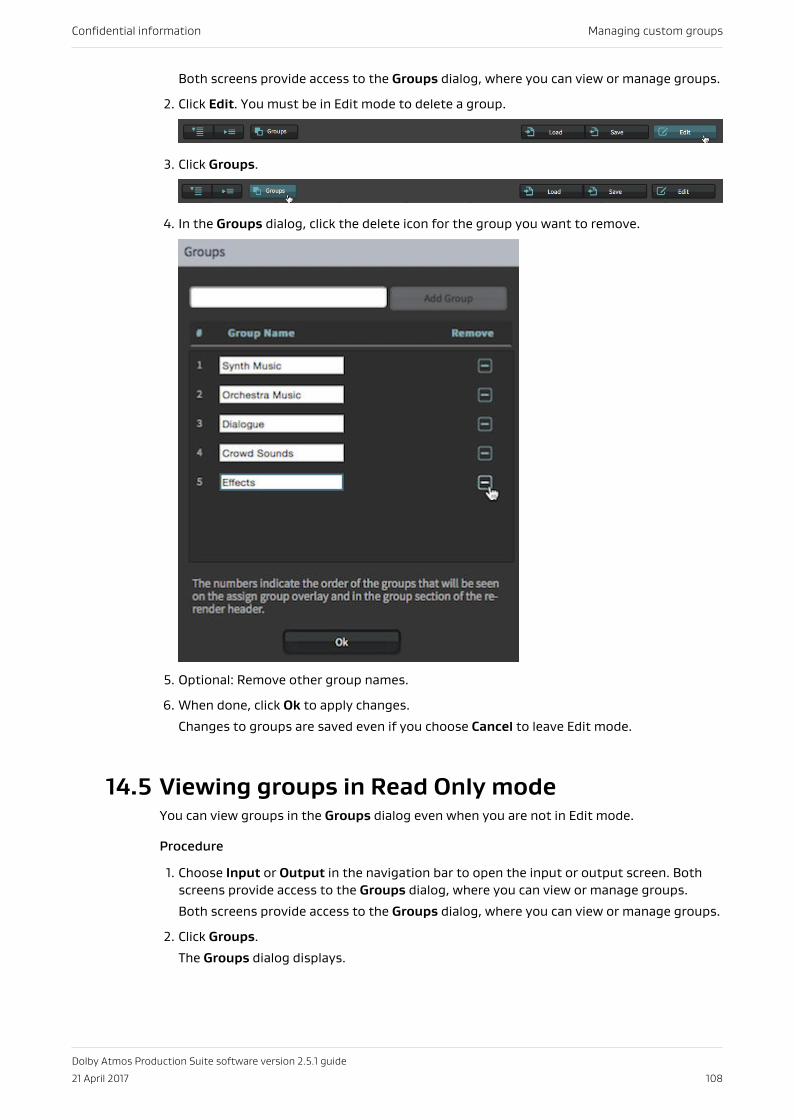
Both screens provide access to the Groups dialog, where you can view or manage groups.
2. Click Edit. You must be in Edit mode to delete a group.
3. Click Groups.
4. In the Groups dialog, click the delete icon for the group you want to remove.
5. Optional: Remove other group names.
6. When done, click Ok to apply changes.
Changes to groups are saved even if you choose Cancel to leave Edit mode.
14.5 Viewing groups in Read Only modeYou can view groups in the Groups dialog even when you are not in Edit mode.
Procedure
1. Choose Input or Output in the navigation bar to open the input or output screen. Bothscreens provide access to the Groups dialog, where you can view or manage groups.
Both screens provide access to the Groups dialog, where you can view or manage groups.
2. Click Groups.
The Groups dialog displays.
Confidential information Managing custom groups
Dolby Atmos Production Suite software version 2.5.1 guide
21 April 2017 108
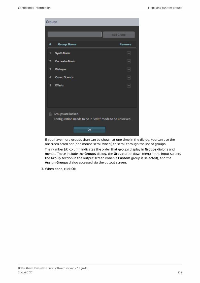
If you have more groups than can be shown at one time in the dialog, you can use theonscreen scroll bar (or a mouse scroll wheel) to scroll through the list of groups.
The number (#) column indicates the order that groups display in Groups dialogs andmenus. These include the Groups dialog, the Group drop-down menu in the input screen,the Group section in the output screen (when a Custom group is selected), and theAssign Groups dialog accessed via the output screen.
3. When done, click Ok.
Confidential information Managing custom groups
Dolby Atmos Production Suite software version 2.5.1 guide
21 April 2017 109
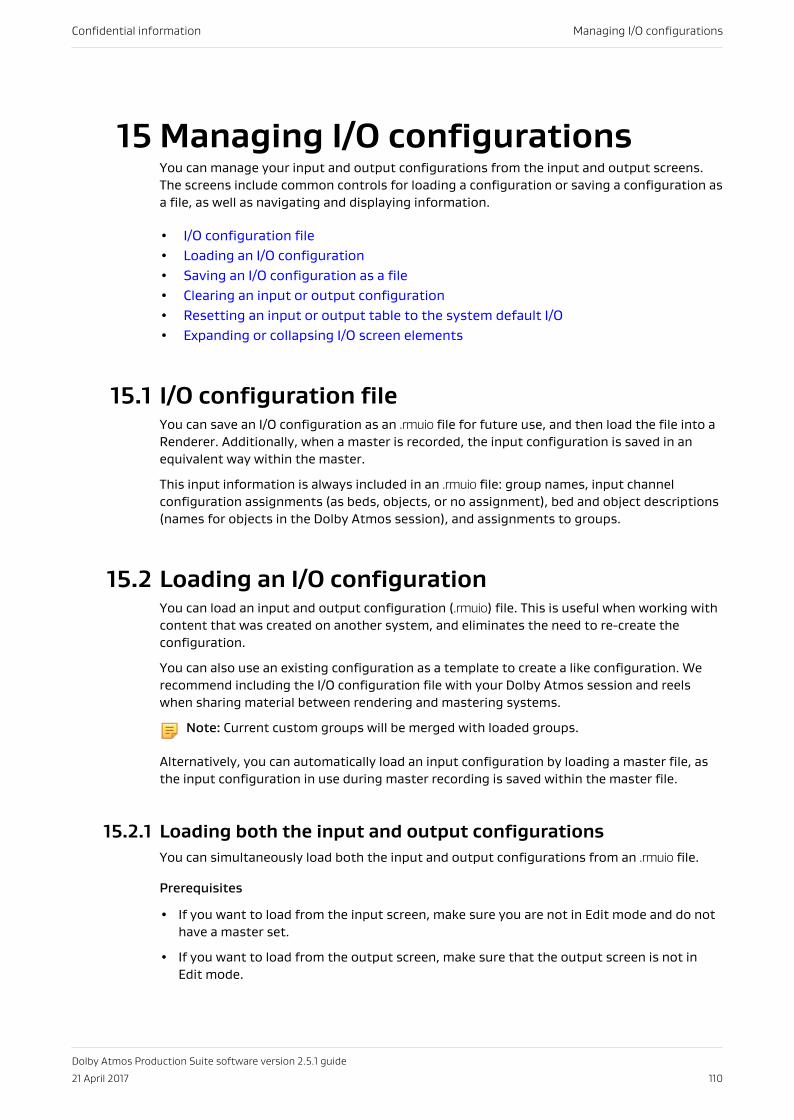
15 Managing I/O configurationsYou can manage your input and output configurations from the input and output screens.The screens include common controls for loading a configuration or saving a configuration asa file, as well as navigating and displaying information.
• I/O configuration file• Loading an I/O configuration• Saving an I/O configuration as a file• Clearing an input or output configuration• Resetting an input or output table to the system default I/O• Expanding or collapsing I/O screen elements
15.1 I/O configuration fileYou can save an I/O configuration as an .rmuio file for future use, and then load the file into aRenderer. Additionally, when a master is recorded, the input configuration is saved in anequivalent way within the master.
This input information is always included in an .rmuio file: group names, input channelconfiguration assignments (as beds, objects, or no assignment), bed and object descriptions(names for objects in the Dolby Atmos session), and assignments to groups.
15.2 Loading an I/O configurationYou can load an input and output configuration (.rmuio) file. This is useful when working withcontent that was created on another system, and eliminates the need to re-create theconfiguration.
You can also use an existing configuration as a template to create a like configuration. Werecommend including the I/O configuration file with your Dolby Atmos session and reelswhen sharing material between rendering and mastering systems.
Note: Current custom groups will be merged with loaded groups.
Alternatively, you can automatically load an input configuration by loading a master file, asthe input configuration in use during master recording is saved within the master file.
15.2.1 Loading both the input and output configurationsYou can simultaneously load both the input and output configurations from an .rmuio file.
Prerequisites
• If you want to load from the input screen, make sure you are not in Edit mode and do nothave a master set.
• If you want to load from the output screen, make sure that the output screen is not inEdit mode.
Confidential information Managing I/O configurations
Dolby Atmos Production Suite software version 2.5.1 guide
21 April 2017 110
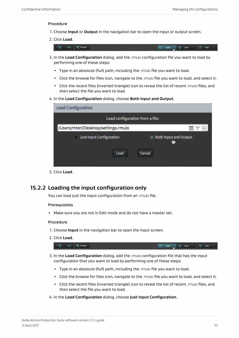
Procedure
1. Choose Input or Output in the navigation bar to open the input or output screen.
2. Click Load.
3. In the Load Configuration dialog, add the .rmuio configuration file you want to load byperforming one of these steps:
• Type in an absolute (full) path, including the .rmuio file you want to load.
• Click the browse for files icon, navigate to the .rmuio file you want to load, and select it.
• Click the recent files (inverted triangle) icon to reveal the list of recent .rmuio files, andthen select the file you want to load.
4. In the Load Configuration dialog, choose Both Input and Output.
5. Click Load.
15.2.2 Loading the input configuration onlyYou can load just the input configuration from an .rmuio file.
Prerequisites
• Make sure you are not in Edit mode and do not have a master set.
Procedure
1. Choose Input in the navigation bar to open the input screen.
2. Click Load.
3. In the Load Configuration dialog, add the .rmuio configuration file that has the inputconfiguration that you want to load by performing one of these steps:
• Type in an absolute (full) path, including the .rmuio file you want to load.
• Click the browse for files icon, navigate to the .rmuio file you want to load, and select it.
• Click the recent files (inverted triangle) icon to reveal the list of recent .rmuio files, andthen select the file you want to load.
4. In the Load Configuration dialog, choose Just Input Configuration.
Confidential information Managing I/O configurations
Dolby Atmos Production Suite software version 2.5.1 guide
21 April 2017 111
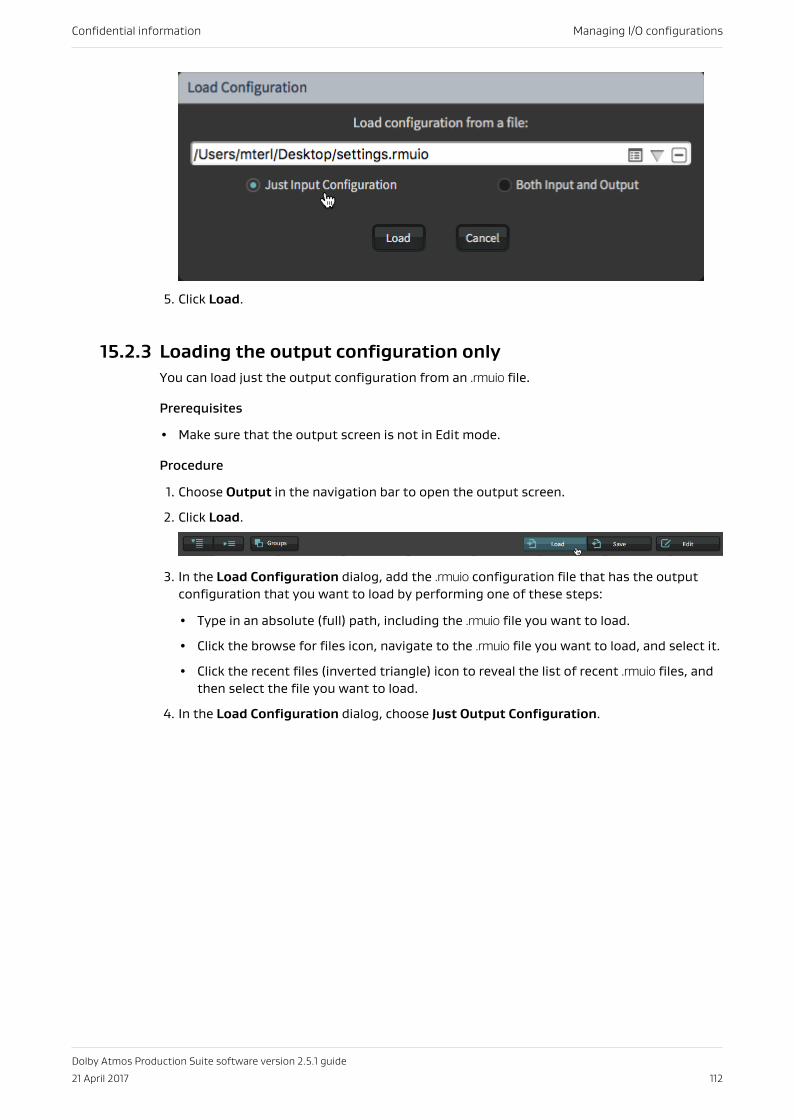
5. Click Load.
15.2.3 Loading the output configuration onlyYou can load just the output configuration from an .rmuio file.
Prerequisites
• Make sure that the output screen is not in Edit mode.
Procedure
1. Choose Output in the navigation bar to open the output screen.
2. Click Load.
3. In the Load Configuration dialog, add the .rmuio configuration file that has the outputconfiguration that you want to load by performing one of these steps:
• Type in an absolute (full) path, including the .rmuio file you want to load.
• Click the browse for files icon, navigate to the .rmuio file you want to load, and select it.
• Click the recent files (inverted triangle) icon to reveal the list of recent .rmuio files, andthen select the file you want to load.
4. In the Load Configuration dialog, choose Just Output Configuration.
Confidential information Managing I/O configurations
Dolby Atmos Production Suite software version 2.5.1 guide
21 April 2017 112
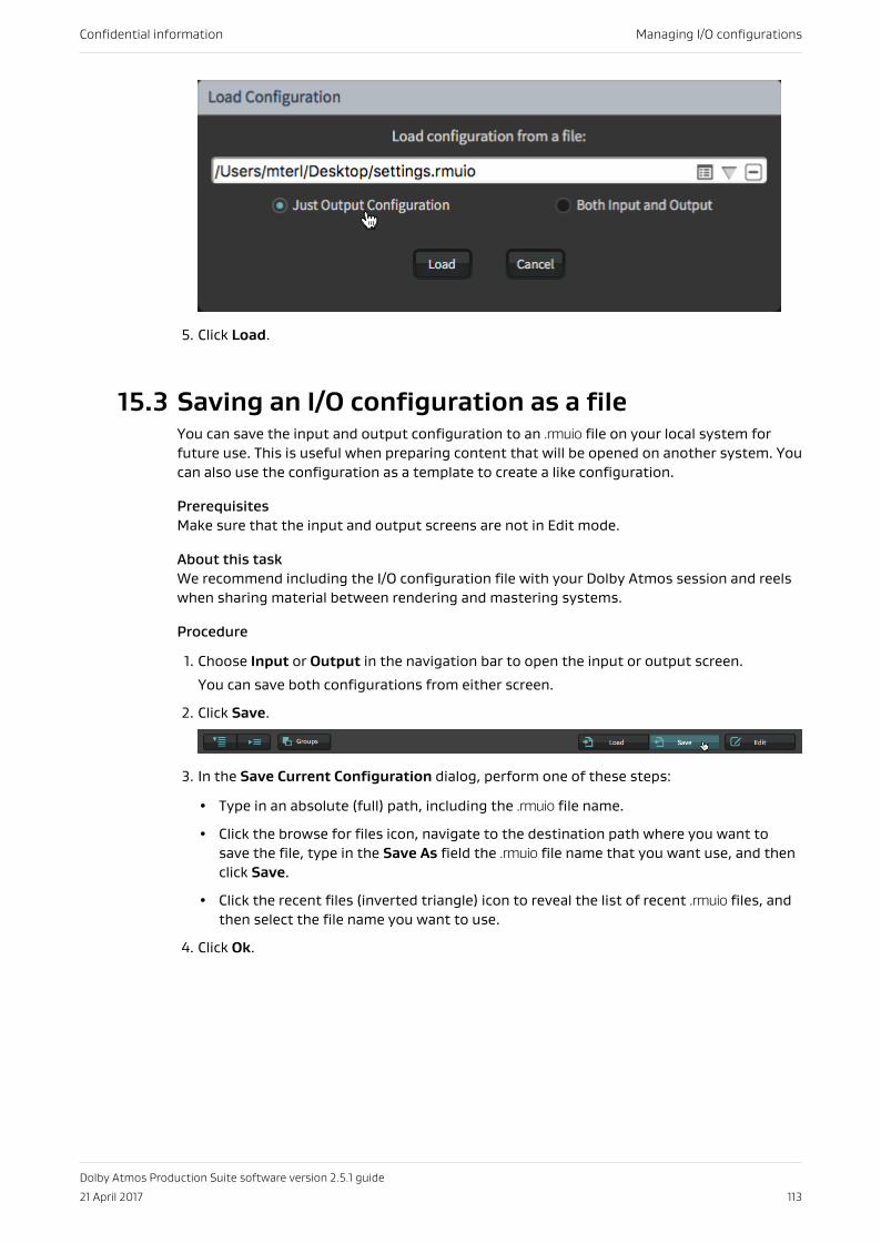
5. Click Load.
15.3 Saving an I/O configuration as a fileYou can save the input and output configuration to an .rmuio file on your local system forfuture use. This is useful when preparing content that will be opened on another system. Youcan also use the configuration as a template to create a like configuration.
PrerequisitesMake sure that the input and output screens are not in Edit mode.
About this taskWe recommend including the I/O configuration file with your Dolby Atmos session and reelswhen sharing material between rendering and mastering systems.
Procedure
1. Choose Input or Output in the navigation bar to open the input or output screen.
You can save both configurations from either screen.
2. Click Save.
3. In the Save Current Configuration dialog, perform one of these steps:
• Type in an absolute (full) path, including the .rmuio file name.
• Click the browse for files icon, navigate to the destination path where you want tosave the file, type in the Save As field the .rmuio file name that you want use, and thenclick Save.
• Click the recent files (inverted triangle) icon to reveal the list of recent .rmuio files, andthen select the file name you want to use.
4. Click Ok.
Confidential information Managing I/O configurations
Dolby Atmos Production Suite software version 2.5.1 guide
21 April 2017 113
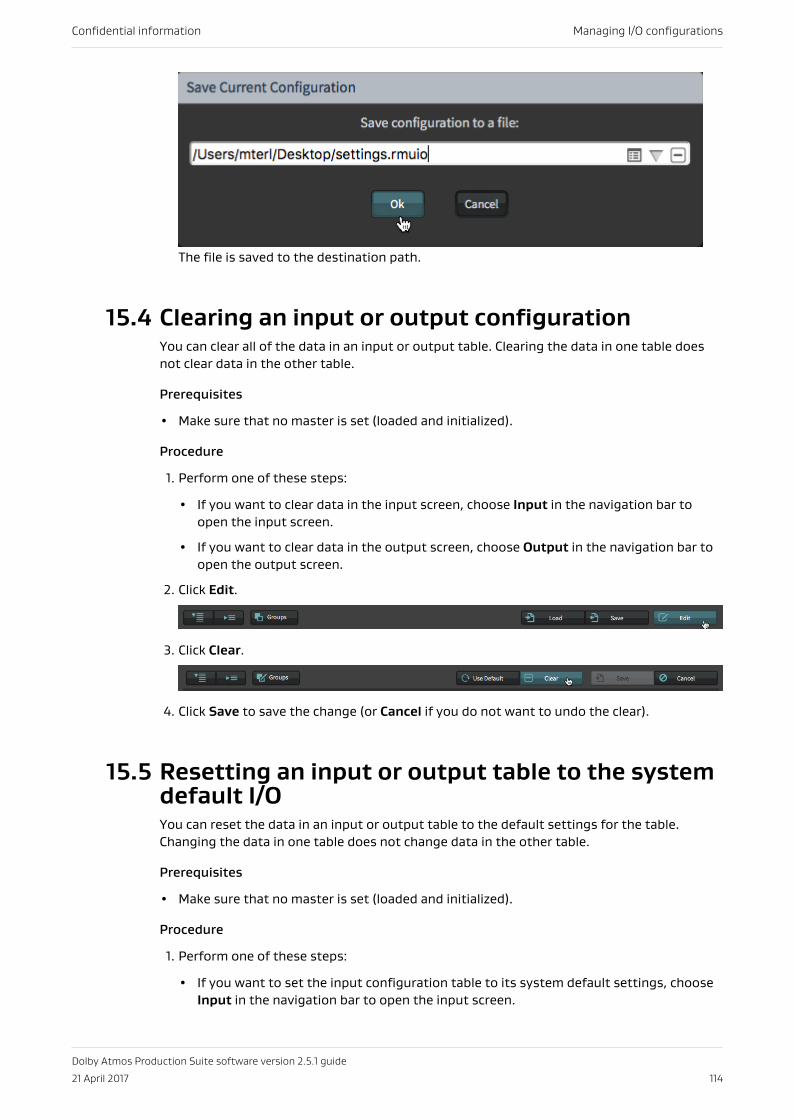
The file is saved to the destination path.
15.4 Clearing an input or output configurationYou can clear all of the data in an input or output table. Clearing the data in one table doesnot clear data in the other table.
Prerequisites
• Make sure that no master is set (loaded and initialized).
Procedure
1. Perform one of these steps:
• If you want to clear data in the input screen, choose Input in the navigation bar toopen the input screen.
• If you want to clear data in the output screen, choose Output in the navigation bar toopen the output screen.
2. Click Edit.
3. Click Clear.
4. Click Save to save the change (or Cancel if you do not want to undo the clear).
15.5 Resetting an input or output table to the systemdefault I/OYou can reset the data in an input or output table to the default settings for the table.Changing the data in one table does not change data in the other table.
Prerequisites
• Make sure that no master is set (loaded and initialized).
Procedure
1. Perform one of these steps:
• If you want to set the input configuration table to its system default settings, chooseInput in the navigation bar to open the input screen.
Confidential information Managing I/O configurations
Dolby Atmos Production Suite software version 2.5.1 guide
21 April 2017 114
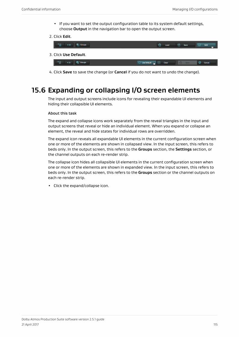
• If you want to set the output configuration table to its system default settings,choose Output in the navigation bar to open the output screen.
2. Click Edit.
3. Click Use Default.
4. Click Save to save the change (or Cancel if you do not want to undo the change).
15.6 Expanding or collapsing I/O screen elementsThe input and output screens include icons for revealing their expandable UI elements andhiding their collapsible UI elements.
About this task
The expand and collapse icons work separately from the reveal triangles in the input andoutput screens that reveal or hide an individual element. When you expand or collapse anelement, the reveal and hide states for individual rows are overridden.
The expand icon reveals all expandable UI elements in the current configuration screen whenone or more of the elements are shown in collapsed view. In the input screen, this refers tobeds only. In the output screen, this refers to the Groups section, the Settings section, orthe channel outputs on each re-render strip.
The collapse icon hides all collapsible UI elements in the current configuration screen whenone or more of the elements are shown in expanded view. In the input screen, this refers tobeds only. In the output screen, this refers to the Groups section or the channel outputs oneach re-render strip.
• Click the expand/collapse icon.
Confidential information Managing I/O configurations
Dolby Atmos Production Suite software version 2.5.1 guide
21 April 2017 115
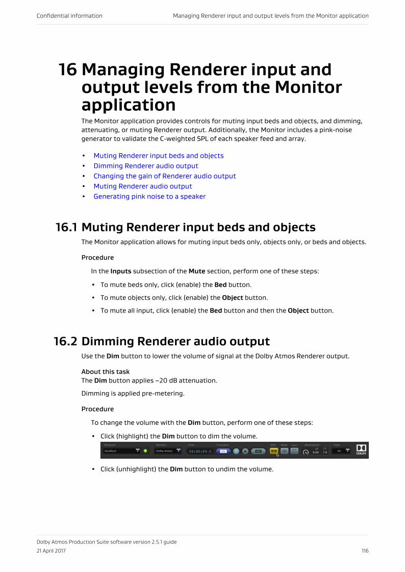
16 Managing Renderer input andoutput levels from the MonitorapplicationThe Monitor application provides controls for muting input beds and objects, and dimming,attenuating, or muting Renderer output. Additionally, the Monitor includes a pink-noisegenerator to validate the C-weighted SPL of each speaker feed and array.
• Muting Renderer input beds and objects• Dimming Renderer audio output• Changing the gain of Renderer audio output• Muting Renderer audio output• Generating pink noise to a speaker
16.1 Muting Renderer input beds and objectsThe Monitor application allows for muting input beds only, objects only, or beds and objects.
Procedure
In the Inputs subsection of the Mute section, perform one of these steps:
• To mute beds only, click (enable) the Bed button.
• To mute objects only, click (enable) the Object button.
• To mute all input, click (enable) the Bed button and then the Object button.
16.2 Dimming Renderer audio outputUse the Dim button to lower the volume of signal at the Dolby Atmos Renderer output.
About this taskThe Dim button applies –20 dB attenuation.
Dimming is applied pre-metering.
Procedure
To change the volume with the Dim button, perform one of these steps:
• Click (highlight) the Dim button to dim the volume.
• Click (unhighlight) the Dim button to undim the volume.
Confidential information Managing Renderer input and output levels from the Monitor application
Dolby Atmos Production Suite software version 2.5.1 guide
21 April 2017 116
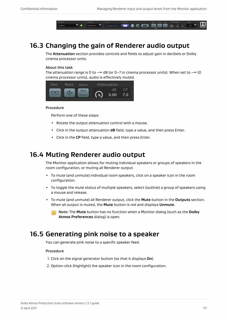
16.3 Changing the gain of Renderer audio outputThe Attenuation section provides controls and fields to adjust gain in decibels or Dolbycinema processor units.
About this taskThe attenuation range is 0 to –∞ dB (or 0–7 in cinema processor units). When set to –∞ (0cinema processor units), audio is effectively muted.
Procedure
Perform one of these steps:
• Rotate the output attenuation control with a mouse.
• Click in the output attenuation dB field, type a value, and then press Enter.
• Click in the CP field, type a value, and then press Enter.
16.4 Muting Renderer audio outputThe Monitor application allows for muting individual speakers or groups of speakers in theroom configuration, or muting all Renderer output.
• To mute (and unmute) individual room speakers, click on a speaker icon in the roomconfiguration.
• To toggle the mute status of multiple speakers, select (outline) a group of speakers usinga mouse and release.
• To mute (and unmute) all Renderer output, click the Mute button in the Outputs section.When all output is muted, the Mute button is red and displays Unmute.
Note: The Mute button has no function when a Monitor dialog (such as the DolbyAtmos Preferences dialog) is open.
16.5 Generating pink noise to a speakerYou can generate pink noise to a specific speaker feed.
Procedure
1. Click on the signal generator button (so that it displays On).
2. Option-click (highlight) the speaker icon in the room configuration.
Confidential information Managing Renderer input and output levels from the Monitor application
Dolby Atmos Production Suite software version 2.5.1 guide
21 April 2017 117
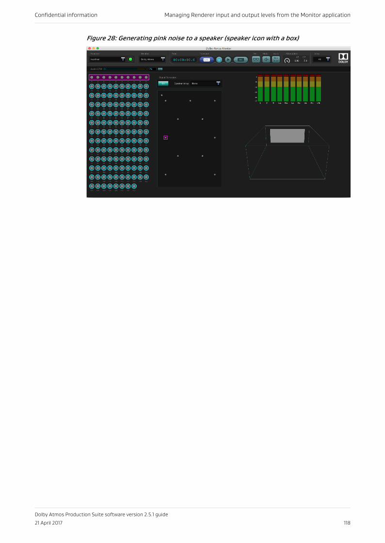
Figure 28: Generating pink noise to a speaker (speaker icon with a box)
Confidential information Managing Renderer input and output levels from the Monitor application
Dolby Atmos Production Suite software version 2.5.1 guide
21 April 2017 118
17 Managing system settings andmaintenanceYou can save (back up), restore, or reset your system settings from the maintenance screen.
• Selecting an operation mode• Rendering and mastering software system settings• Backing up system settings• Restoring (loading) system settings• Resetting system settings• Troubleshooting
17.1 Selecting an operation modeAfter launching the Renderer, you can choose the operating mode for your content creationworkflow: VR or home theater. Each mode includes features and controls specific to theirworkflow.
About this task
Changing modes replaces your current settings with the default settings for the new mode.
Procedure
1. Choose Maintenance in the navigation bar to open the maintenance screen.
2. In the Mode section, perform one of these steps:
• For VR content creation, click (check) VR.
• For home theater content creation, click (check) Home Theater.
3. For access to the Settings menu and additional Monitoring controls, click Expert.
17.2 Rendering and mastering software systemsettingsRenderer settings are saved as a .dac file. You can use the .dac file to restore your settings,and when doing so, you can choose to restore all system settings or to restore from a list ofspecific settings.
Note: The .dac files saved from the Renderer are formatted differently from .dac filescreated with other Dolby rendering software or the Dolby Atmos calibration tool.The .dac files from these separate products are not compatible with the Renderer.
Note: Input and Output screen settings are not considered system settings and havetheir own dedicated Default button to return to their default values.
Confidential information Managing system settings and maintenance
Dolby Atmos Production Suite software version 2.5.1 guide
21 April 2017 119
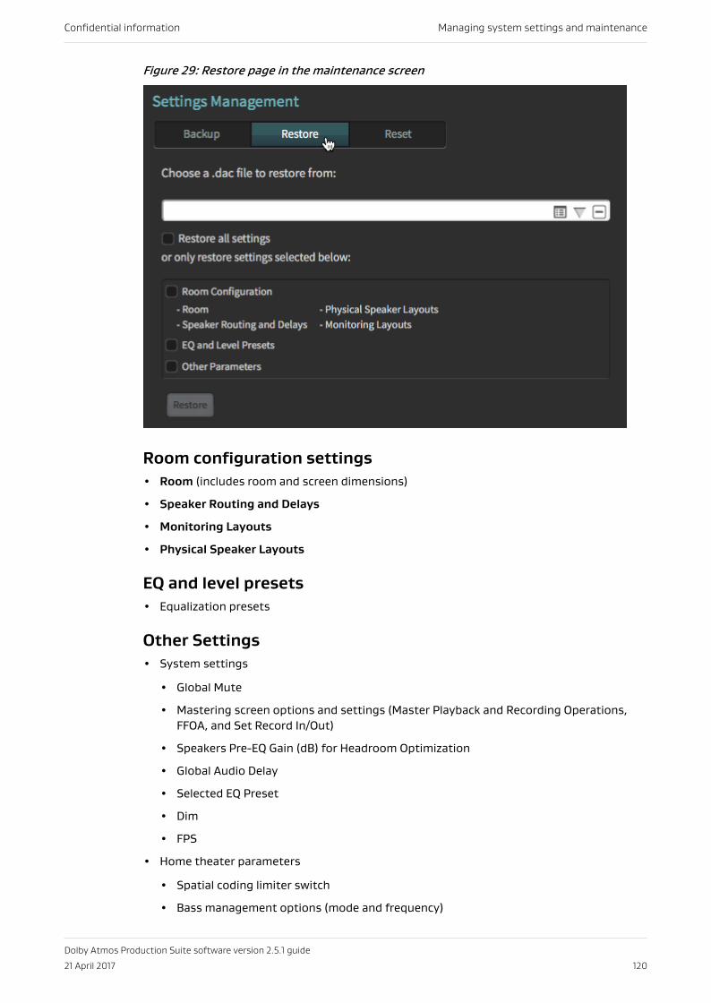
Figure 29: Restore page in the maintenance screen
Room configuration settings• Room (includes room and screen dimensions)
• Speaker Routing and Delays
• Monitoring Layouts
• Physical Speaker Layouts
EQ and level presets• Equalization presets
Other Settings• System settings
• Global Mute
• Mastering screen options and settings (Master Playback and Recording Operations,FFOA, and Set Record In/Out)
• Speakers Pre-EQ Gain (dB) for Headroom Optimization
• Global Audio Delay
• Selected EQ Preset
• Dim
• FPS
• Home theater parameters
• Spatial coding limiter switch
• Bass management options (mode and frequency)
Confidential information Managing system settings and maintenance
Dolby Atmos Production Suite software version 2.5.1 guide
21 April 2017 120
• Spatial coding configuration (number of elements, output beds, buffer size)
17.3 Backing up system settingsYou can back up system settings for future retrieval, or to share with another facility. Systemsettings are saved as a .dac file.
Procedure
1. Choose Maintenance in the navigation bar to open the maintenance screen.
2. In the Settings management section, click the Backup button.
3. Enter the name of the file in the Back up all system settings to a file on a local drivefield.
4. Click the Create Backup button.
17.4 Restoring (loading) system settingsYou can restore (load) system settings by loading a preexisting .dac file.
About this task
When restoring settings, the current Renderer mode (VR or Home Theater) and the Expertoption setting is maintained.
Procedure
1. Choose Maintenance in the navigation bar to open the maintenance screen.
2. At the top of the Settings management section, click the Restore button.
3. Click the Browse button.
4. Navigate to the location of the .dac file that you want to load, select it, and click Open.
5. Click the Restore all system settings option box to restore room configuration, EQ andlevel presets, and other parameters, or click individual option boxes to select individualsettings.
6. Click the Restore button at the bottom of the Settings Management section to load thesettings.
17.5 Resetting system settingsYou can reset system settings to their default values. Performing a reset removes anypreviously loaded Dolby Atmos configuration file. A system setting reset cannot be undone.Consider running a backup first, and then performing a reset.
About this task
After the Renderer resets system settings, the Renderer mode is set to Home Theater, withthe Expert option disabled.
Confidential information Managing system settings and maintenance
Dolby Atmos Production Suite software version 2.5.1 guide
21 April 2017 121
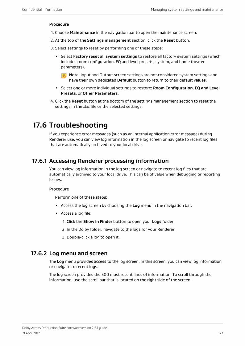
Procedure
1. Choose Maintenance in the navigation bar to open the maintenance screen.
2. At the top of the Settings management section, click the Reset button.
3. Select settings to reset by performing one of these steps:
• Select Factory reset all system settings to restore all factory system settings (whichincludes room configuration, EQ and level presets, system, and home theaterparameters).
Note: Input and Output screen settings are not considered system settings andhave their own dedicated Default button to return to their default values.
• Select one or more individual settings to restore: Room Configuration, EQ and LevelPresets, or Other Parameters.
4. Click the Reset button at the bottom of the settings management section to reset thesettings in the .dac file or the selected settings.
17.6 TroubleshootingIf you experience error messages (such as an internal application error message) duringRenderer use, you can view log information in the log screen or navigate to recent log filesthat are automatically archived to your local drive.
17.6.1 Accessing Renderer processing informationYou can view log information in the log screen or navigate to recent log files that areautomatically archived to your local drive. This can be of value when debugging or reportingissues.
Procedure
Perform one of these steps:
• Access the log screen by choosing the Log menu in the navigation bar.
• Access a log file:
1. Click the Show in Finder button to open your Logs folder.
2. In the Dolby folder, navigate to the logs for your Renderer.
3. Double-click a log to open it.
17.6.2 Log menu and screenThe Log menu provides access to the log screen. In this screen, you can view log informationor navigate to recent logs.
The log screen provides the 500 most recent lines of information. To scroll through theinformation, use the scroll bar that is located on the right side of the screen.
Confidential information Managing system settings and maintenance
Dolby Atmos Production Suite software version 2.5.1 guide
21 April 2017 122
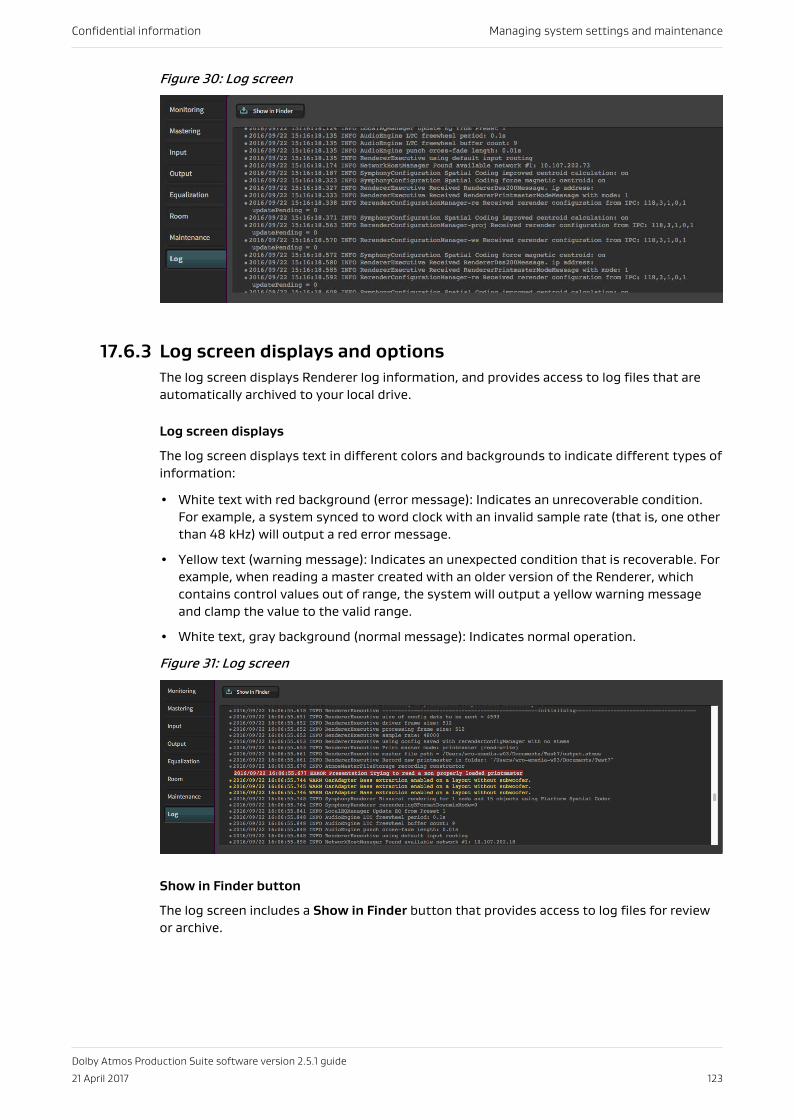
Figure 30: Log screen
17.6.3 Log screen displays and optionsThe log screen displays Renderer log information, and provides access to log files that areautomatically archived to your local drive.
Log screen displays
The log screen displays text in different colors and backgrounds to indicate different types ofinformation:
• White text with red background (error message): Indicates an unrecoverable condition.For example, a system synced to word clock with an invalid sample rate (that is, one otherthan 48 kHz) will output a red error message.
• Yellow text (warning message): Indicates an unexpected condition that is recoverable. Forexample, when reading a master created with an older version of the Renderer, whichcontains control values out of range, the system will output a yellow warning messageand clamp the value to the valid range.
• White text, gray background (normal message): Indicates normal operation.
Figure 31: Log screen
Show in Finder button
The log screen includes a Show in Finder button that provides access to log files for reviewor archive.
Confidential information Managing system settings and maintenance
Dolby Atmos Production Suite software version 2.5.1 guide
21 April 2017 123
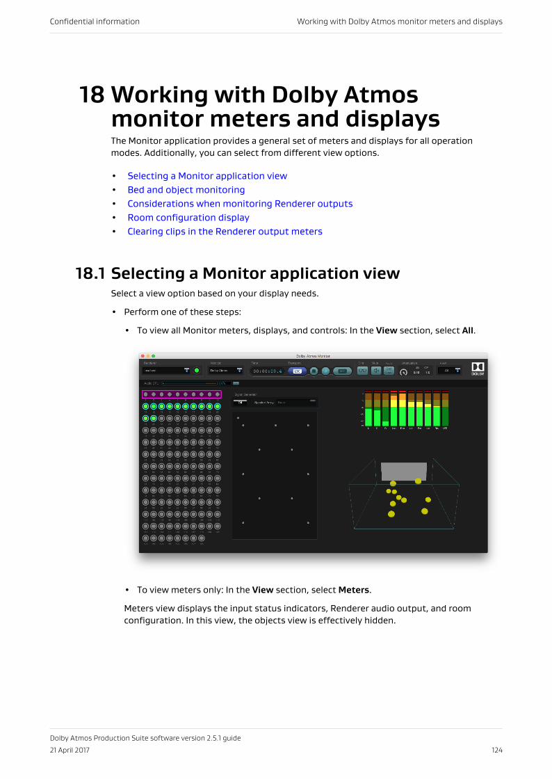
18 Working with Dolby Atmosmonitor meters and displaysThe Monitor application provides a general set of meters and displays for all operationmodes. Additionally, you can select from different view options.
• Selecting a Monitor application view• Bed and object monitoring• Considerations when monitoring Renderer outputs• Room configuration display• Clearing clips in the Renderer output meters
18.1 Selecting a Monitor application viewSelect a view option based on your display needs.
• Perform one of these steps:
• To view all Monitor meters, displays, and controls: In the View section, select All.
• To view meters only: In the View section, select Meters.
Meters view displays the input status indicators, Renderer audio output, and roomconfiguration. In this view, the objects view is effectively hidden.
Confidential information Working with Dolby Atmos monitor meters and displays
Dolby Atmos Production Suite software version 2.5.1 guide
21 April 2017 124
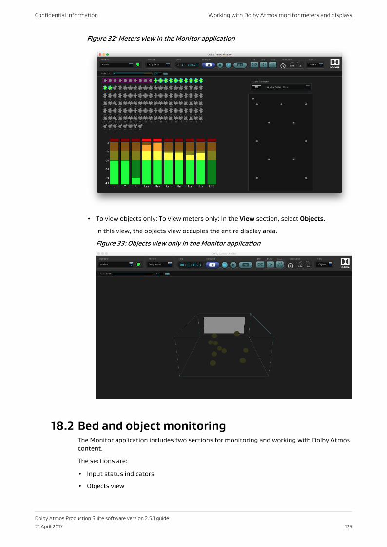
Figure 32: Meters view in the Monitor application
• To view objects only: To view meters only: In the View section, select Objects.
In this view, the objects view occupies the entire display area.
Figure 33: Objects view only in the Monitor application
18.2 Bed and object monitoringThe Monitor application includes two sections for monitoring and working with Dolby Atmoscontent.
The sections are:
• Input status indicators
• Objects view
Confidential information Working with Dolby Atmos monitor meters and displays
Dolby Atmos Production Suite software version 2.5.1 guide
21 April 2017 125
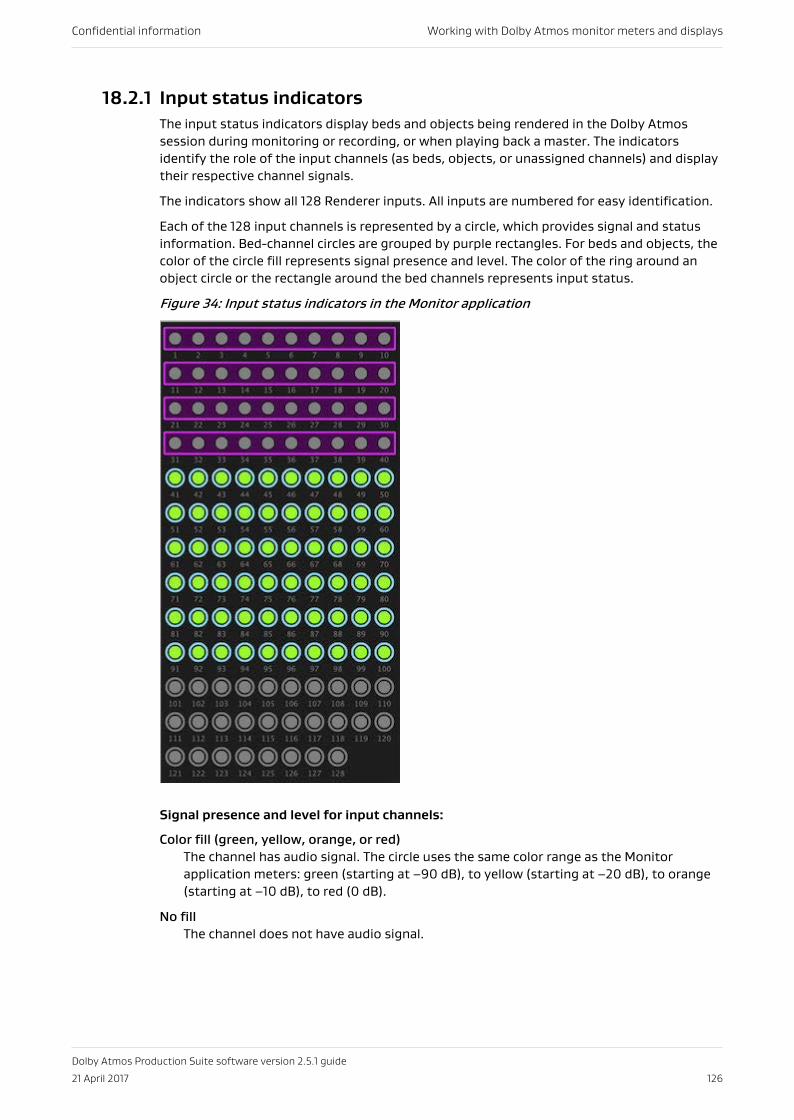
18.2.1 Input status indicatorsThe input status indicators display beds and objects being rendered in the Dolby Atmossession during monitoring or recording, or when playing back a master. The indicatorsidentify the role of the input channels (as beds, objects, or unassigned channels) and displaytheir respective channel signals.
The indicators show all 128 Renderer inputs. All inputs are numbered for easy identification.
Each of the 128 input channels is represented by a circle, which provides signal and statusinformation. Bed-channel circles are grouped by purple rectangles. For beds and objects, thecolor of the circle fill represents signal presence and level. The color of the ring around anobject circle or the rectangle around the bed channels represents input status.
Figure 34: Input status indicators in the Monitor application
Signal presence and level for input channels:
Color fill (green, yellow, orange, or red)The channel has audio signal. The circle uses the same color range as the Monitorapplication meters: green (starting at –90 dB), to yellow (starting at –20 dB), to orange(starting at –10 dB), to red (0 dB).
No fillThe channel does not have audio signal.
Confidential information Working with Dolby Atmos monitor meters and displays
Dolby Atmos Production Suite software version 2.5.1 guide
21 April 2017 126
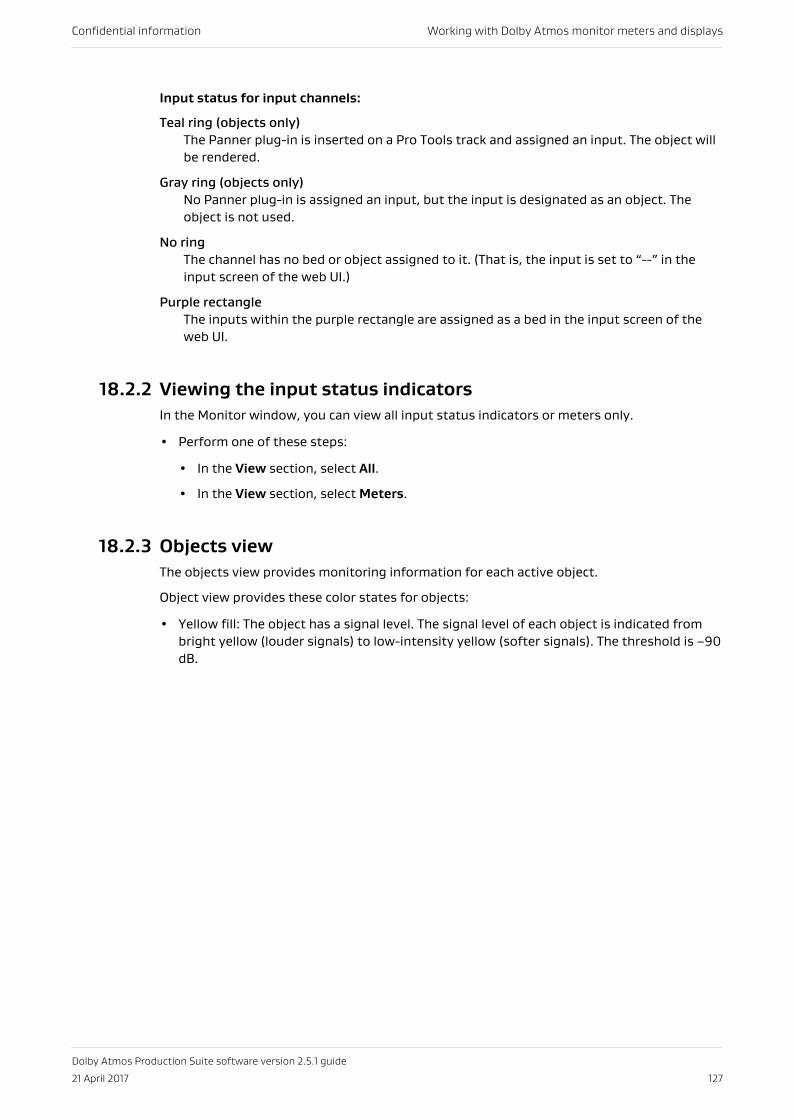
Input status for input channels:
Teal ring (objects only)The Panner plug-in is inserted on a Pro Tools track and assigned an input. The object willbe rendered.
Gray ring (objects only)No Panner plug-in is assigned an input, but the input is designated as an object. Theobject is not used.
No ringThe channel has no bed or object assigned to it. (That is, the input is set to “--” in theinput screen of the web UI.)
Purple rectangleThe inputs within the purple rectangle are assigned as a bed in the input screen of theweb UI.
18.2.2 Viewing the input status indicatorsIn the Monitor window, you can view all input status indicators or meters only.
• Perform one of these steps:
• In the View section, select All.
• In the View section, select Meters.
18.2.3 Objects viewThe objects view provides monitoring information for each active object.
Object view provides these color states for objects:
• Yellow fill: The object has a signal level. The signal level of each object is indicated frombright yellow (louder signals) to low-intensity yellow (softer signals). The threshold is −90dB.
Confidential information Working with Dolby Atmos monitor meters and displays
Dolby Atmos Production Suite software version 2.5.1 guide
21 April 2017 127
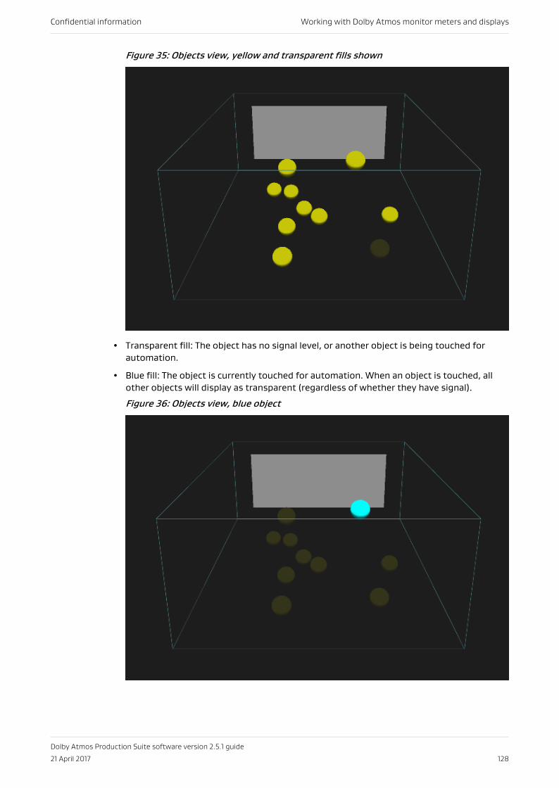
Figure 35: Objects view, yellow and transparent fills shown
• Transparent fill: The object has no signal level, or another object is being touched forautomation.
• Blue fill: The object is currently touched for automation. When an object is touched, allother objects will display as transparent (regardless of whether they have signal).
Figure 36: Objects view, blue object
Confidential information Working with Dolby Atmos monitor meters and displays
Dolby Atmos Production Suite software version 2.5.1 guide
21 April 2017 128
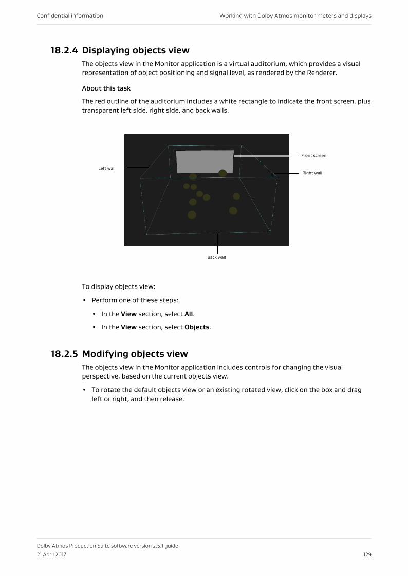
18.2.4 Displaying objects viewThe objects view in the Monitor application is a virtual auditorium, which provides a visualrepresentation of object positioning and signal level, as rendered by the Renderer.
About this task
The red outline of the auditorium includes a white rectangle to indicate the front screen, plustransparent left side, right side, and back walls.
Left wallRight wall
Back wall
Front screen
To display objects view:
• Perform one of these steps:
• In the View section, select All.
• In the View section, select Objects.
18.2.5 Modifying objects viewThe objects view in the Monitor application includes controls for changing the visualperspective, based on the current objects view.
• To rotate the default objects view or an existing rotated view, click on the box and dragleft or right, and then release.
Confidential information Working with Dolby Atmos monitor meters and displays
Dolby Atmos Production Suite software version 2.5.1 guide
21 April 2017 129
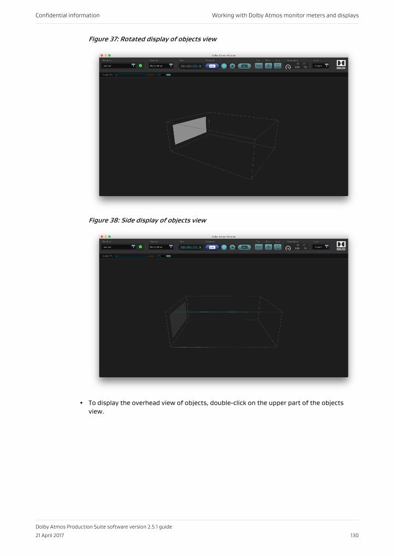
Figure 37: Rotated display of objects view
Figure 38: Side display of objects view
• To display the overhead view of objects, double-click on the upper part of the objectsview.
Confidential information Working with Dolby Atmos monitor meters and displays
Dolby Atmos Production Suite software version 2.5.1 guide
21 April 2017 130
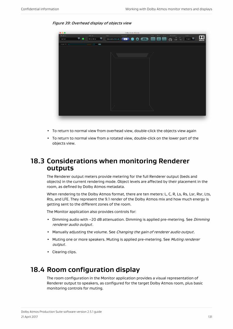
Figure 39: Overhead display of objects view
• To return to normal view from overhead view, double-click the objects view again
• To return to normal view from a rotated view, double-click on the lower part of theobjects view.
18.3 Considerations when monitoring RendereroutputsThe Renderer output meters provide metering for the full Renderer output (beds andobjects) in the current rendering mode. Object levels are affected by their placement in theroom, as defined by Dolby Atmos metadata.
When rendering to the Dolby Atmos format, there are ten meters: L, C, R, Ls, Rs, Lsr, Rsr, Lts,Rts, and LFE. They represent the 9.1 render of the Dolby Atmos mix and how much energy isgetting sent to the different zones of the room.
The Monitor application also provides controls for:
• Dimming audio with –20 dB attenuation. Dimming is applied pre-metering. See Dimmingrenderer audio output .
• Manually adjusting the volume. See Changing the gain of renderer audio output .
• Muting one or more speakers. Muting is applied pre-metering. See Muting rendereroutput .
• Clearing clips.
18.4 Room configuration displayThe room configuration in the Monitor application provides a visual representation ofRenderer output to speakers, as configured for the target Dolby Atmos room, plus basicmonitoring controls for muting.
Confidential information Working with Dolby Atmos monitor meters and displays
Dolby Atmos Production Suite software version 2.5.1 guide
21 April 2017 131
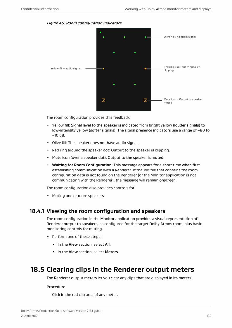
Figure 40: Room configuration indicators
Yellow fill = audio signal
Olive fill = no audio signal
Mute icon = Output to speaker muted
Red ring = output to speaker clipping
The room configuration provides this feedback:
• Yellow fill: Signal level to the speaker is indicated from bright yellow (louder signals) tolow-intensity yellow (softer signals). The signal presence indicators use a range of –80 to–10 dB.
• Olive fill: The speaker does not have audio signal.
• Red ring around the speaker dot: Output to the speaker is clipping.
• Mute icon (over a speaker dot): Output to the speaker is muted.
• Waiting for Room Configuration: This message appears for a short time when firstestablishing communication with a Renderer. If the .dac file that contains the roomconfiguration data is not found on the Renderer (or the Monitor application is notcommunicating with the Renderer), the message will remain onscreen.
The room configuration also provides controls for:
• Muting one or more speakers
18.4.1 Viewing the room configuration and speakersThe room configuration in the Monitor application provides a visual representation ofRenderer output to speakers, as configured for the target Dolby Atmos room, plus basicmonitoring controls for muting.
• Perform one of these steps:
• In the View section, select All.
• In the View section, select Meters.
18.5 Clearing clips in the Renderer output metersThe Renderer output meters let you clear any clips that are displayed in its meters.
Procedure
Click in the red clip area of any meter.
Confidential information Working with Dolby Atmos monitor meters and displays
Dolby Atmos Production Suite software version 2.5.1 guide
21 April 2017 132
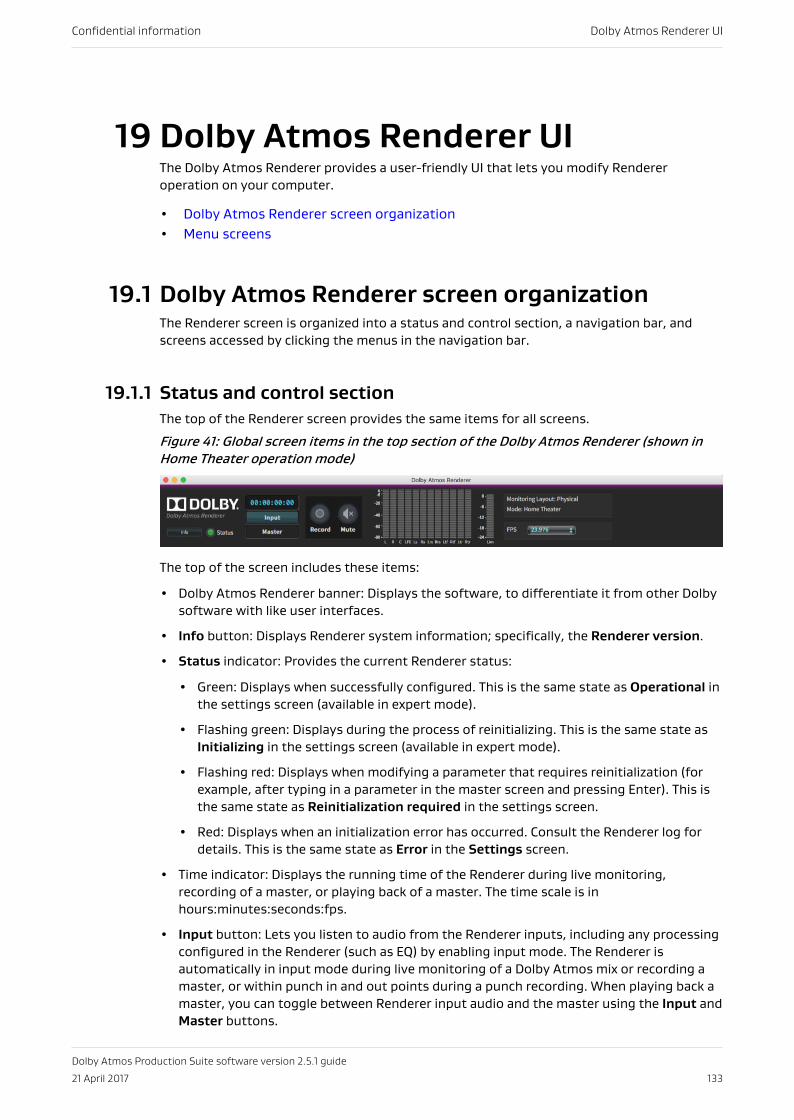
19 Dolby Atmos Renderer UIThe Dolby Atmos Renderer provides a user-friendly UI that lets you modify Rendereroperation on your computer.
• Dolby Atmos Renderer screen organization• Menu screens
19.1 Dolby Atmos Renderer screen organizationThe Renderer screen is organized into a status and control section, a navigation bar, andscreens accessed by clicking the menus in the navigation bar.
19.1.1 Status and control sectionThe top of the Renderer screen provides the same items for all screens.
Figure 41: Global screen items in the top section of the Dolby Atmos Renderer (shown inHome Theater operation mode)
The top of the screen includes these items:
• Dolby Atmos Renderer banner: Displays the software, to differentiate it from other Dolbysoftware with like user interfaces.
• Info button: Displays Renderer system information; specifically, the Renderer version.
• Status indicator: Provides the current Renderer status:
• Green: Displays when successfully configured. This is the same state as Operational inthe settings screen (available in expert mode).
• Flashing green: Displays during the process of reinitializing. This is the same state asInitializing in the settings screen (available in expert mode).
• Flashing red: Displays when modifying a parameter that requires reinitialization (forexample, after typing in a parameter in the master screen and pressing Enter). This isthe same state as Reinitialization required in the settings screen.
• Red: Displays when an initialization error has occurred. Consult the Renderer log fordetails. This is the same state as Error in the Settings screen.
• Time indicator: Displays the running time of the Renderer during live monitoring,recording of a master, or playing back of a master. The time scale is inhours:minutes:seconds:fps.
• Input button: Lets you listen to audio from the Renderer inputs, including any processingconfigured in the Renderer (such as EQ) by enabling input mode. The Renderer isautomatically in input mode during live monitoring of a Dolby Atmos mix or recording amaster, or within punch in and out points during a punch recording. When playing back amaster, you can toggle between Renderer input audio and the master using the Input andMaster buttons.
Confidential information Dolby Atmos Renderer UI
Dolby Atmos Production Suite software version 2.5.1 guide
21 April 2017 133
• Master button: Lets you listen to audio from the loaded master file by enabling Mastermode. Use Master mode when playing back a master. The Renderer is automatically inMaster mode after a master is loaded and set, as well as outside punch in and out pointsduring a punch recording. When playing back a master, you can toggle between Rendererinput audio and the master using the Input and Master buttons.
• Record indicator: Displays the recording status of the Renderer for all recordingoperations. The indicator provides these states:
• Gray: This occurs when the Monitor record arm is off and the Enable Record In/Outoption in the mastering screen is off.
• Yellow: This occurs when the Enable Record In/Out option in the mastering screen ison, and the Monitor record arm is off.
• Flashing red: This occurs when the recording is armed in the Monitor and Dolby Atmosaudio and data are not being written to a master. For example, for a boundedrecording, the indicator flashes before the transport reaches the In point defined inthe mastering screen.
• Solid red: This occurs during recording when Dolby Atmos audio and data are beingwritten to a master. For a bounded recording, the indicator stays solid red from the Inpoint to the Out point (both defined in the mastering screen).
• Mute/Unmute button: Mutes or unmutes the signals passing through the Renderer. Thisbutton mirrors the behavior of the mute button in the Monitor application.
• Metering: Provides signal levels for speaker feeds, the built-in limiter, and binaural levels(in dBFS) of 0, ‑6, ‑20, ‑40, ‑60, ‑80:
• Speaker feed meters: Provide metering of the speaker feeds for the active monitorlayout (room configuration). The display shows the meters for the current monitorlayout only. These meters display when the Speaker monitoring option is set to on inthe Monitor screen.
• Limiter meter: Displays the amount of limiting provided when the global home theaterlimiter control is on.
Limiting affects monitoring at the outputs only. It does not affect what is recorded tothe master during master recording. Limiting is performed here to provide an accuraterepresentation of the limiting applied during encoding by the Dolby Media Encoder (fora home theater master) or Dolby Atmos VR Transcoder (for a VR master). The controlto switch off limiting is provided mainly as a diagnostic tool.
• Binaural meters: These meters display when the Binaural monitoring option is set toon in the Monitor screen.
• Monitoring Layout display: Provides visual reference of the current monitoring layout, asset in monitoring screen. Layouts include: Physical, 7.1.4, 7.1, 5.1, and 2.0.
• Mode display: Provides visual reference of the current Renderer operation mode, as set inmaintenance screen. Modes display as VR, Home Theater, VR-expert, and HomeTheater-expert.
• FPS drop-down menu: Displays the master timecode rate (in fps) for an existing master,or lets you set the timecode rate for a new master recording (to match the timecode rateof the Pro Tools session and RME DSP settings). Available rates include: 23.976, 24, 25,29.97, 29.97 DF, and 30.
When loading an existing master, the menu automatically updates to the mastertimecode, turns gray, and cannot be changed. The menu also turns gray and cannot bechanged for playback operations (such as playback and audition).
Confidential information Dolby Atmos Renderer UI
Dolby Atmos Production Suite software version 2.5.1 guide
21 April 2017 134
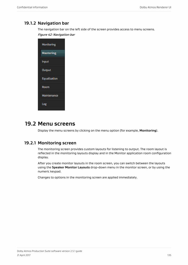
19.1.2 Navigation barThe navigation bar on the left side of the screen provides access to menu screens.
Figure 42: Navigation bar
19.2 Menu screensDisplay the menu screens by clicking on the menu option (for example, Monitoring).
19.2.1 Monitoring screenThe monitoring screen provides custom layouts for listening to output. The room layout isreflected in the monitoring layouts display and in the Monitor application room configurationdisplay.
After you create monitor layouts in the room screen, you can switch between the layoutsusing the Speaker Monitor Layouts drop-down menu in the monitor screen, or by using thenumeric keypad.
Changes to options in the monitoring screen are applied immediately.
Confidential information Dolby Atmos Renderer UI
Dolby Atmos Production Suite software version 2.5.1 guide
21 April 2017 135
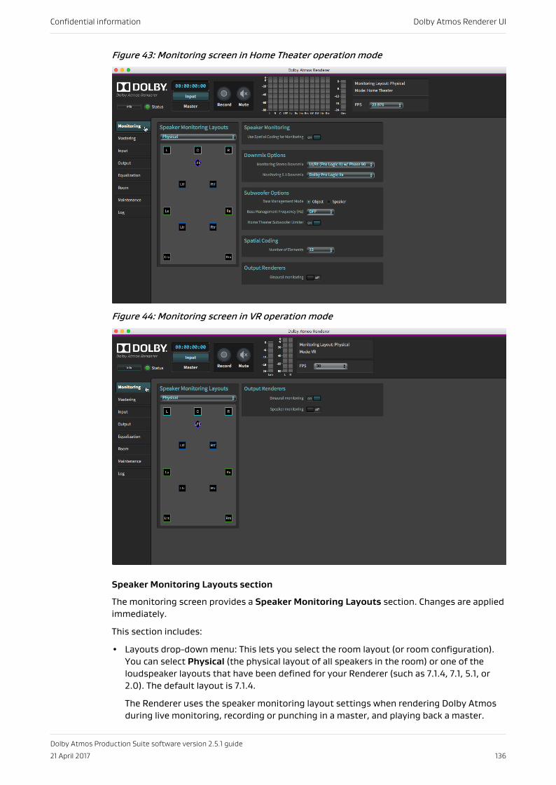
Figure 43: Monitoring screen in Home Theater operation mode
Figure 44: Monitoring screen in VR operation mode
Speaker Monitoring Layouts section
The monitoring screen provides a Speaker Monitoring Layouts section. Changes are appliedimmediately.
This section includes:
• Layouts drop-down menu: This lets you select the room layout (or room configuration).You can select Physical (the physical layout of all speakers in the room) or one of theloudspeaker layouts that have been defined for your Renderer (such as 7.1.4, 7.1, 5.1, or2.0). The default layout is 7.1.4.
The Renderer uses the speaker monitoring layout settings when rendering Dolby Atmosduring live monitoring, recording or punching in a master, and playing back a master.
Confidential information Dolby Atmos Renderer UI
Dolby Atmos Production Suite software version 2.5.1 guide
21 April 2017 136
The selected room layout is reflected in the Speaker Monitoring Layouts section and inthe Dolby Atmos Monitor application room configuration display. The selected layoutdoes not affect the recorded data when recording a new master.
• Room configuration display: This provides display of the selected monitoring layout.
Speakers Monitoring section
The Speakers Monitoring section provides different options depending on the operationmode.
• Use Spatial Coding for Monitoring (home theater mode, or VR mode with expert modeenabled): Applies spatial coding to signal routed to monitors.
Note: When preparing content that will be part of a mix (for example, material by adialogue editor), we recommend turning off spatial coding for monitoring, becausespatial coding is designed to be applied to a full mix.
Downmix Options section
All downmix options are available in home theater mode, or VR mode with expert modeenabled.
Monitoring Stereo Downmix: When a 2.0 monitor layout is selected (in the output screen),this control selects the stereo downmix, which will be folded down or rendered to stereofrom the .atmos content.
These downmix options are supported:
• Lt/Rt (Legacy) w/ Phase 90
• Lt/Rt (Pro Logic II) w/ Phase 90 (default, preferred)
• Lo/Ro w/ Phase 90
• Lt/Rt (Legacy)
• Lt/Rt (Pro Logic II)
• Lo/Ro
• Stereo Direct Render
Note: The downmix type for re-renders must be set on the output screen.
Note: The phase 90 filters used provide the all-pass 90-degree phase shift filtering forthe Ls/Rs feeds into the downmix, which reduces undesirable signal cancellation,improves imaging, and enables proper matrix decoding. It is strongly recommended touse the 90-degree phase shift for any Lt/Rt downmixes.
All the stereo downmix options except Stereo Direct Render are created by first creating a5.1 downmix from the 7.1 re-render of.atmos content, and then downmixing the 5.1 to 2.0 inthe same manner as 2.0 consumer products
The coefficients for the two-channel downmixes from 5.1 are:
Lt/Rt (Legacy):
Lt = L + (–3 dB x C) – (–3 dB x Ls) – (–3 dB x Rs)Rt = R + (–3 dB x C) + (–3 dB x Ls) + (–3 dB x Rs)
Lt/Rt (Pro Logic II):
Lt = L + (–3 dB x C) – (–1.2 dB x Ls) – (–6.2 dB x Rs)Rt = R + (–3 dB x C) + (–6.2 dB x Ls) + (–1.2 dB x Rs)
LoRo:
Confidential information Dolby Atmos Renderer UI
Dolby Atmos Production Suite software version 2.5.1 guide
21 April 2017 137
Lo = L + (–3 dB x C) + (–3 dB x Ls)Ro = R + (–3 dB x C) + (–3 dB x Rs)
Monitoring 5.1 Downmix: When 5.1 monitor layout is selected (in the output screen), thiscontrol selects the 5.1 downmix, which will be folded down or rendered to 5.1 fromthe .atmos content.
These downmix options are supported:
• Dolby Pro Logic IIx
• Standard
• 5.1 Direct Render
The coefficients for a Dolby Pro Logic PLIIx downmix from 7.1 to 5.1 are:
Ls = Lss + (–1.2dB x Lrs) + (–6.2dB x Rrs)Rs = Rss + (–6.2dB x Lrs) + (–1.2dB x Rrs)
The coefficients for a Standard downmix from 7.1 to 5.1 are:
Ls = 0 dB x Lss + 0 dB x LrsRs = 0 dB x Rss + 0 dB x Rrs
Subwoofer Options section
All subwoofer are available in home theater mode, or VR mode with expert mode enabled.
Bass Management Mode: This control lets you reduce bass buildup when objects are sent tomultiple speaker feeds in the bass management system.
• Select Object to handle bass extraction from object signals before they are rendered tospeaker feeds, reducing object-bass buildup.
• Select Speaker to emulate traditional bass management systems, which process speakerfeeds instead.
Bass Management Frequency (Hz): This setting defines the frequency at which bass isremoved from full-range outputs and routed to LFE. Settings include OFF and commonfrequencies between 45 and 200 Hz. By default, the setting is off.
Home Theater Subwoofer Limiter button: This on/off control sets whether subwooferlimiting is applied to the subwoofer signal during monitoring. Such limiting is a commonfeature of consumer subwoofer systems and home-theater-in-a-box products. Low-frequency limiting is not reflected in the limiting meter, and is not applied during recordingor bitstream encoding.
Spatial Coding section
All spatial coding options are available in home theater mode, or VR mode with expert modeenabled.
Number of Elements: This drop-down menu sets the number of clustered object signals plusbed signals of Dolby Atmos material for spatial coding. With home theater rendering, bedinput signals that are not specifically reserved in an output bed configuration are treated asobjects, with a fixed position in space. These static objects are combined with dynamicmoving objects, and all of these are processed by spatial coding, to produce the final outputsignal. Valid values are from 12, 14, and 16.
Output Renderers section
The Output Renderers section provides different options depending on the operation mode.
Confidential information Dolby Atmos Renderer UI
Dolby Atmos Production Suite software version 2.5.1 guide
21 April 2017 138
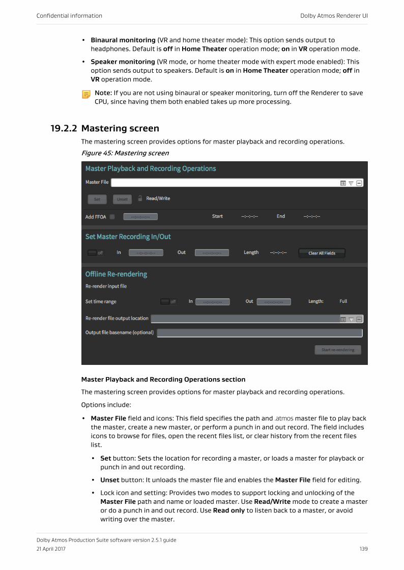
• Binaural monitoring (VR and home theater mode): This option sends output toheadphones. Default is off in Home Theater operation mode; on in VR operation mode.
• Speaker monitoring (VR mode, or home theater mode with expert mode enabled): Thisoption sends output to speakers. Default is on in Home Theater operation mode; off inVR operation mode.
Note: If you are not using binaural or speaker monitoring, turn off the Renderer to saveCPU, since having them both enabled takes up more processing.
19.2.2 Mastering screenThe mastering screen provides options for master playback and recording operations.
Figure 45: Mastering screen
Master Playback and Recording Operations section
The mastering screen provides options for master playback and recording operations.
Options include:
• Master File field and icons: This field specifies the path and .atmos master file to play backthe master, create a new master, or perform a punch in and out record. The field includesicons to browse for files, open the recent files list, or clear history from the recent fileslist.
• Set button: Sets the location for recording a master, or loads a master for playback orpunch in and out recording.
• Unset button: It unloads the master file and enables the Master File field for editing.
• Lock icon and setting: Provides two modes to support locking and unlocking of theMaster File path and name or loaded master. Use Read/Write mode to create a masteror do a punch in and out record. Use Read only to listen back to a master, or avoidwriting over the master.
Confidential information Dolby Atmos Renderer UI
Dolby Atmos Production Suite software version 2.5.1 guide
21 April 2017 139
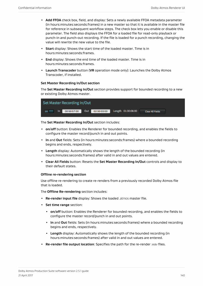
• Add FFOA check box, field, and display: Sets a newly available FFOA metadata parameter(in hours:minutes:seconds:frames) in a new master so that it is available in the master filefor reference in subsequent workflow steps. The check box lets you enable or disable thisparameter. The field also displays the FFOA for a loaded file for read-only playback orpunch-in and punch-out recording. If the file is loaded for a punch recording, changing thevalue will rewrite the new value to the file.
• Start display: Shows the start time of the loaded master. Time is inhours:minutes:seconds:frames.
• End display: Shows the end time of the loaded master. Time is inhours:minutes:seconds:frames.
• Launch Transcoder button (VR operation mode only): Launches the Dolby AtmosTranscoder, if installed.
Set Master Recording In/Out section
The Set Master Recording In/Out section provides support for bounded recording to a newor existing Dolby Atmos master.
The Set Master Recording In/Out section includes:
• on/off button: Enables the Renderer for bounded recording, and enables the fields toconfigure the master record/punch in and out points.
• In and Out fields: Sets (in hours:minutes:seconds:frames) where a bounded recordingbegins and ends, respectively.
• Length display: Automatically shows the length of the bounded recording (inhours:minutes:seconds:frames) after valid in and out values are entered.
• Clear All Fields button: Resets the Set Master Recording In/Out controls and display totheir default states.
Offline re-rendering section
Use offline re-rendering to create re-renders from a previously recorded Dolby Atmos filethat is loaded.
The Offline Re-rendering section includes:
• Re-render input file display: Shows the loaded .atmos master file.
• Set time range section:
• on/off button: Enables the Renderer for bounded recording, and enables the fields toconfigure the master record/punch in and out points.
• In and Out fields: Sets (in hours:minutes:seconds:frames) where a bounded recordingbegins and ends, respectively.
• Length display: Automatically shows the length of the bounded recording (inhours:minutes:seconds:frames) after valid in and out values are entered.
• Re-render file output location: Specifies the path for the re-render .wav files.
Confidential information Dolby Atmos Renderer UI
Dolby Atmos Production Suite software version 2.5.1 guide
21 April 2017 140
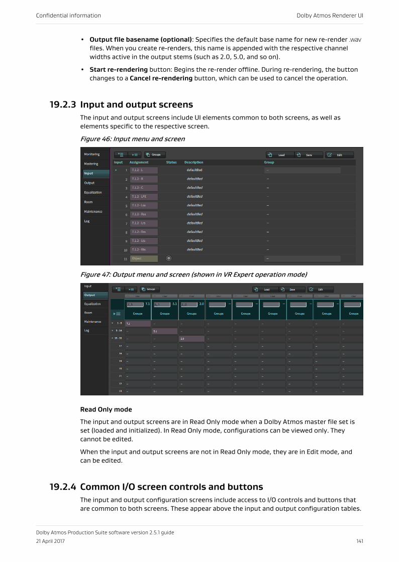
• Output file basename (optional): Specifies the default base name for new re-render .wavfiles. When you create re-renders, this name is appended with the respective channelwidths active in the output stems (such as 2.0, 5.0, and so on).
• Start re-rendering button: Begins the re-render offline. During re-rendering, the buttonchanges to a Cancel re-rendering button, which can be used to cancel the operation.
19.2.3 Input and output screensThe input and output screens include UI elements common to both screens, as well aselements specific to the respective screen.
Figure 46: Input menu and screen
Figure 47: Output menu and screen (shown in VR Expert operation mode)
Read Only mode
The input and output screens are in Read Only mode when a Dolby Atmos master file set isset (loaded and initialized). In Read Only mode, configurations can be viewed only. Theycannot be edited.
When the input and output screens are not in Read Only mode, they are in Edit mode, andcan be edited.
19.2.4 Common I/O screen controls and buttonsThe input and output configuration screens include access to I/O controls and buttons thatare common to both screens. These appear above the input and output configuration tables.
Confidential information Dolby Atmos Renderer UI
Dolby Atmos Production Suite software version 2.5.1 guide
21 April 2017 141
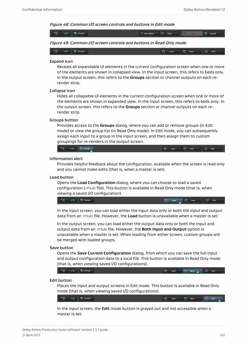
Figure 48: Common I/O screen controls and buttons in Edit mode
Figure 49: Common I/O screen controls and buttons in Read Only mode
Expand iconReveals all expandable UI elements in the current configuration screen when one or moreof the elements are shown in collapsed view. In the input screen, this refers to beds only.In the output screen, this refers to the Groups section or channel outputs on each re-render strip.
Collapse iconHides all collapsible UI elements in the current configuration screen when one or more ofthe elements are shown in expanded view. In the input screen, this refers to beds only. Inthe output screen, this refers to the Groups section or channel outputs on each re-render strip.
Groups buttonProvides access to the Groups dialog, where you can add or remove groups (in Editmode) or view the group list (in Read Only mode). In Edit mode, you can subsequentlyassign each input to a group in the input screen, and then assign them to customgroupings for re-renders in the output screen.
Information alertProvides helpful feedback about the configuration, available when the screen is read onlyand you cannot make edits (that is, when a master is set).
Load buttonOpens the Load Configuration dialog, where you can choose to load a savedconfiguration (.rmuio file). This button is available in Read Only mode (that is, whenviewing a saved I/O configuration).
In the input screen, you can load either the input data only or both the input and outputdata from an .rmuio file. However, the Load button is unavailable when a master is set.
In the output screen, you can load either the output data only or both the input andoutput data from an .rmuio file. However, the Both Input and Output option isunavailable when a master is set. When loading from either screen, custom groups willbe merged with loaded groups.
Save buttonOpens the Save Current Configuration dialog, from which you can save the full inputand output configuration data to a local file. This button is available in Read Only mode(that is, when viewing saved I/O configurations).
Edit buttonPlaces the input and output screens in Edit mode. This button is available in Read Onlymode (that is, when viewing saved I/O configurations).
In the input screen, the Edit mode button is grayed out and not accessible when amaster is set.
Confidential information Dolby Atmos Renderer UI
Dolby Atmos Production Suite software version 2.5.1 guide
21 April 2017 142
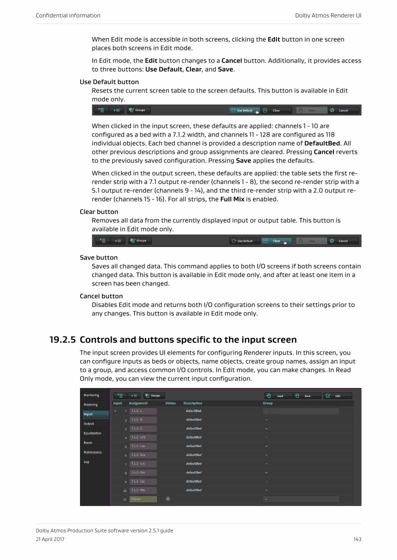
When Edit mode is accessible in both screens, clicking the Edit button in one screenplaces both screens in Edit mode.
In Edit mode, the Edit button changes to a Cancel button. Additionally, it provides accessto three buttons: Use Default, Clear, and Save.
Use Default buttonResets the current screen table to the screen defaults. This button is available in Editmode only.
When clicked in the input screen, these defaults are applied: channels 1 - 10 areconfigured as a bed with a 7.1.2 width, and channels 11 - 128 are configured as 118individual objects. Each bed channel is provided a description name of DefaultBed. Allother previous descriptions and group assignments are cleared. Pressing Cancel revertsto the previously saved configuration. Pressing Save applies the defaults.
When clicked in the output screen, these defaults are applied: the table sets the first re-render strip with a 7.1 output re-render (channels 1 - 8), the second re-render strip with a5.1 output re-render (channels 9 - 14), and the third re-render strip with a 2.0 output re-render (channels 15 - 16). For all strips, the Full Mix is enabled.
Clear buttonRemoves all data from the currently displayed input or output table. This button isavailable in Edit mode only.
Save buttonSaves all changed data. This command applies to both I/O screens if both screens containchanged data. This button is available in Edit mode only, and after at least one item in ascreen has been changed.
Cancel buttonDisables Edit mode and returns both I/O configuration screens to their settings prior toany changes. This button is available in Edit mode only.
19.2.5 Controls and buttons specific to the input screenThe input screen provides UI elements for configuring Renderer inputs. In this screen, youcan configure inputs as beds or objects, name objects, create group names, assign an inputto a group, and access common I/O controls. In Edit mode, you can make changes. In ReadOnly mode, you can view the current input configuration.
Confidential information Dolby Atmos Renderer UI
Dolby Atmos Production Suite software version 2.5.1 guide
21 April 2017 143
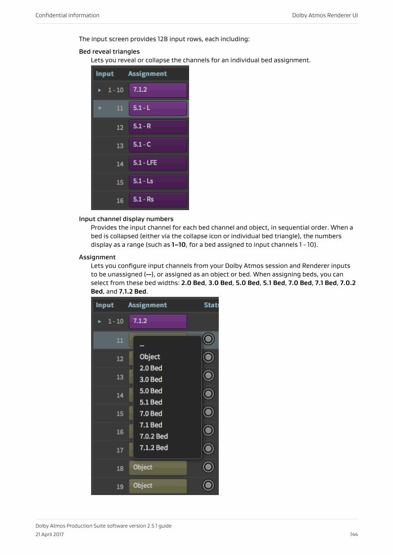
The input screen provides 128 input rows, each including:
Bed reveal trianglesLets you reveal or collapse the channels for an individual bed assignment.
Input channel display numbersProvides the input channel for each bed channel and object, in sequential order. When abed is collapsed (either via the collapse icon or individual bed triangle), the numbersdisplay as a range (such as 1–10, for a bed assigned to input channels 1 - 10).
AssignmentLets you configure input channels from your Dolby Atmos session and Renderer inputsto be unassigned (--), or assigned as an object or bed. When assigning beds, you canselect from these bed widths: 2.0 Bed, 3.0 Bed, 5.0 Bed, 5.1 Bed, 7.0 Bed, 7.1 Bed, 7.0.2Bed, and 7.1.2 Bed.
Confidential information Dolby Atmos Renderer UI
Dolby Atmos Production Suite software version 2.5.1 guide
21 April 2017 144
When input channels are unassigned or assigned as a bed, the respective object numberwill not be available in the Panner plug-in Object selector in the Dolby Atmos Pro Toolssession.
When assigned to an object, the object description is applied to its respective Panner inthe Dolby Atmos Pro Tools session.
Status displaysProvides status and signal presence for objects, and signal presence only for beds. Thedisplay states in the input screen are the same as those for beds in the Monitorapplication input status indicators:
• Green fill: The bed or object has audio signal (starting at –93 dBFS). Bed channelsdisplay a circle only when audio is present.
• No fill: The object does not have audio signal. Bed channels display a circle only whenaudio is present.
• Green ring: The input is designated as an object, and the Panner plug-in is inserted onthe associated Pro Tools track, and assigned an input. The object will be rendered.
• Gray ring: No Panner plug-in is assigned an input, but the input is designated as anobject. The object is not used.
DescriptionLets you provide your own description for configured beds and objects, including theability to update object names in Panner plug-ins in the Dolby Atmos session (remotely,from the Renderer application). For a bed, the description is applied to each channel ofthe bed in the input configuration. You cannot have different descriptions for differentchannels within the same bed. For objects, you can apply descriptions on a per-objectbasis. In turn, each object description is applied to its respective Panner in the DolbyAtmos session. The description appears in the Panner plug-in description drop-downmenu (formerly the Object Number box) and in the Object selector (formerly the ObjectID selector).
Confidential information Dolby Atmos Renderer UI
Dolby Atmos Production Suite software version 2.5.1 guide
21 April 2017 145
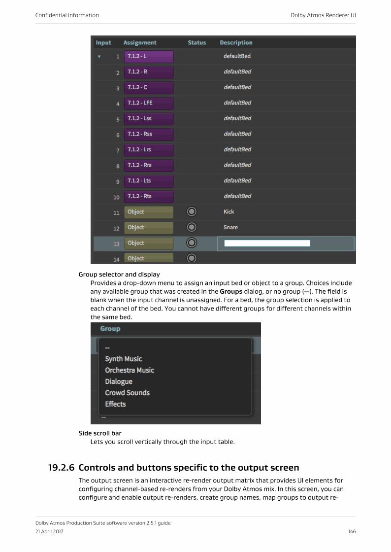
Group selector and displayProvides a drop-down menu to assign an input bed or object to a group. Choices includeany available group that was created in the Groups dialog, or no group (--). The field isblank when the input channel is unassigned. For a bed, the group selection is applied toeach channel of the bed. You cannot have different groups for different channels withinthe same bed.
Side scroll barLets you scroll vertically through the input table.
19.2.6 Controls and buttons specific to the output screenThe output screen is an interactive re-render output matrix that provides UI elements forconfiguring channel-based re-renders from your Dolby Atmos mix. In this screen, you canconfigure and enable output re-renders, create group names, map groups to output re-
Confidential information Dolby Atmos Renderer UI
Dolby Atmos Production Suite software version 2.5.1 guide
21 April 2017 146
renders, and access common I/O commands. In Edit mode, you can make changes. In ReadOnly mode, you can view the current output configuration.
Re-render Options
The output screen includes a Re-renderer Options section with three drop-down menus forcreating stereo and 5.1 downmixes, as well as B-format versions of Dolby Atmos material (inVR mode, or home theater mode with expert mode enabled).
2.0: When a 2.0 monitor layout is selected (in an output strip), this control selects the stereodownmix, which will be folded down or rendered to stereo from the .atmos content.
These downmix options are supported:
• Lt/Rt (legacy) with phase 90
• Lt/Rt (Dolby Pro Logic II) with phase 90 (default, preferred)
• Lo/Ro with phase 90
• Lt/Rt (legacy)
• Lt/Rt (Dolby Pro Logic II)
• Lo/Ro
• Stereo direct render
• Use monitoring selection
Note: The downmix type for mastering must be set on the output configuration page.
Note: The phase 90 filters used provide the allpass 90-degree phase-shift filtering forthe Ls/Rs feeds into the downmix, which reduces undesirable signal cancellation,improves imaging, and enables proper matrix decoding. We strongly recommend usingthe 90-degree phase shift for any Lt/Rt downmixes.
All of the stereo downmix options except Stereo Direct Render are created by first creatinga 5.1 downmix from the 7.1 re-render of .atmos content, and then downmixing the 5.1 to 2.0 inthe same manner as 2.0 consumer products.
The coefficients for the two-channel downmixes from 5.1 are:
Lt/Rt (legacy):
Lt = L + (–3 dB × C) – (–3 dB × Ls) – (–3 dB × Rs)Rt = R + (–3 dB × C) + (–3 dB × Ls) + (–3 dB × Rs)
Lt/Rt (Dolby Pro Logic II):
Lt = L + (–3 dB × C) – (–1.2 dB × Ls) – (–6.2 dB × Rs)Rt = R + (–3 dB × C) + (–6.2 dB × Ls) + (–1.2 dB × Rs)
Lo/Ro:
Lo = L + (–3 dB × C) + (–3 dB × Ls)Ro = R + (–3 dB × C) + (–3 dB × Rs)
5.1: When 5.1 monitor layout is selected (in an output strip), this control selects the 5.1downmix, which will be folded down or rendered to 5.1 from the .atmos content.
These downmix options are supported:
• Dolby Pro Logic IIx
• Standard
Confidential information Dolby Atmos Renderer UI
Dolby Atmos Production Suite software version 2.5.1 guide
21 April 2017 147
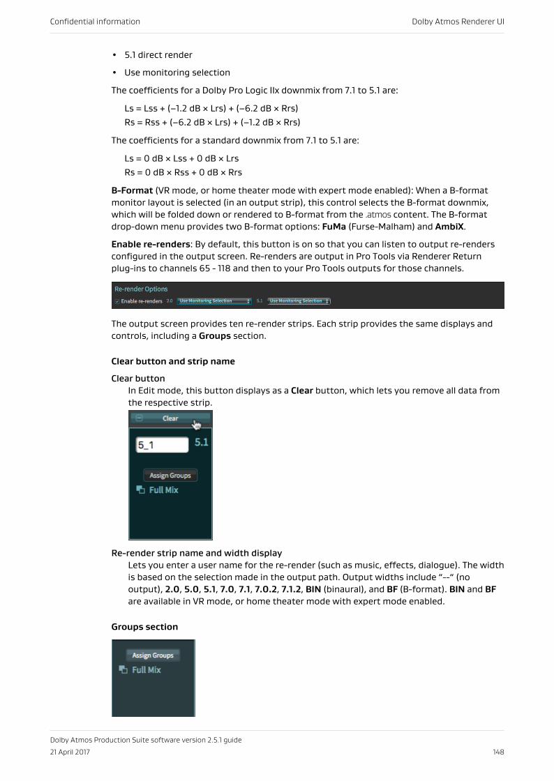
• 5.1 direct render
• Use monitoring selection
The coefficients for a Dolby Pro Logic IIx downmix from 7.1 to 5.1 are:
Ls = Lss + (–1.2 dB × Lrs) + (–6.2 dB × Rrs)Rs = Rss + (–6.2 dB × Lrs) + (–1.2 dB × Rrs)
The coefficients for a standard downmix from 7.1 to 5.1 are:
Ls = 0 dB × Lss + 0 dB × LrsRs = 0 dB × Rss + 0 dB × Rrs
B-Format (VR mode, or home theater mode with expert mode enabled): When a B-formatmonitor layout is selected (in an output strip), this control selects the B-format downmix,which will be folded down or rendered to B-format from the .atmos content. The B-formatdrop-down menu provides two B-format options: FuMa (Furse-Malham) and AmbiX.
Enable re-renders: By default, this button is on so that you can listen to output re-rendersconfigured in the output screen. Re-renders are output in Pro Tools via Renderer Returnplug-ins to channels 65 - 118 and then to your Pro Tools outputs for those channels.
The output screen provides ten re-render strips. Each strip provides the same displays andcontrols, including a Groups section.
Clear button and strip name
Clear buttonIn Edit mode, this button displays as a Clear button, which lets you remove all data fromthe respective strip.
Re-render strip name and width displayLets you enter a user name for the re-render (such as music, effects, dialogue). The widthis based on the selection made in the output path. Output widths include “--“ (nooutput), 2.0, 5.0, 5.1, 7.0, 7.1, 7.0.2, 7.1.2, BIN (binaural), and BF (B-format). BIN and BFare available in VR mode, or home theater mode with expert mode enabled.
Groups section
Confidential information Dolby Atmos Renderer UI
Dolby Atmos Production Suite software version 2.5.1 guide
21 April 2017 148
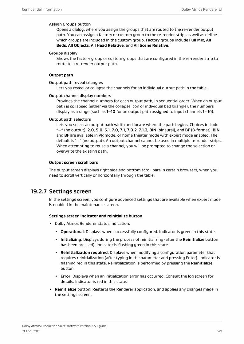
Assign Groups buttonOpens a dialog, where you assign the groups that are routed to the re-render outputpath. You can assign a factory or custom group to the re-render strip, as well as definewhich groups are included in the custom group. Factory groups include Full Mix, AllBeds, All Objects, All Head Relative, and All Scene Relative.
Groups displayShows the factory group or custom groups that are configured in the re-render strip toroute to a re-render output path.
Output path
Output path reveal trianglesLets you reveal or collapse the channels for an individual output path in the table.
Output channel display numbersProvides the channel numbers for each output path, in sequential order. When an outputpath is collapsed (either via the collapse icon or individual bed triangle), the numbersdisplay as a range (such as 1–10 for an output path assigned to input channels 1 - 10).
Output path selectorsLets you select an output path width and locate where the path begins. Choices include“--“ (no output), 2.0, 5.0, 5.1, 7.0, 7.1, 7.0.2, 7.1.2, BIN (binaural), and BF (B-format). BINand BF are available in VR mode, or home theater mode with expert mode enabled. Thedefault is “--“ (no output). An output channel cannot be used in multiple re-render strips.When attempting to reuse a channel, you will be prompted to change the selection oroverwrite the existing path.
Output screen scroll bars
The output screen displays right side and bottom scroll bars in certain browsers, when youneed to scroll vertically or horizontally through the table.
19.2.7 Settings screenIn the settings screen, you configure advanced settings that are available when expert modeis enabled in the maintenance screen.
Settings screen indicator and reinitialize button
• Dolby Atmos Renderer status indication:
• Operational: Displays when successfully configured. Indicator is green in this state.
• Initializing: Displays during the process of reinitializing (after the Reinitialize buttonhas been pressed). Indicator is flashing green in this state.
• Reinitialization required: Displays when modifying a configuration parameter thatrequires reinitialization (after typing in the parameter and pressing Enter). Indicator isflashing red in this state. Reinitialization is performed by pressing the Reinitializebutton.
• Error: Displays when an initialization error has occurred. Consult the log screen fordetails. Indicator is red in this state.
• Reinitialize button: Restarts the Renderer application, and applies any changes made inthe settings screen.
Confidential information Dolby Atmos Renderer UI
Dolby Atmos Production Suite software version 2.5.1 guide
21 April 2017 149
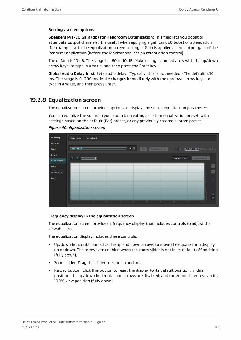
Settings screen options
Speakers Pre-EQ Gain (db) for Headroom Optimization: This field lets you boost orattenuate output channels. It is useful when applying significant EQ boost or attenuation(for example, with the equalization screen settings). Gain is applied at the output gain of theRenderer application (before the Monitor application attenuation control).
The default is 10 dB. The range is –60 to 10 dB. Make changes immediately with the up/downarrow keys, or type in a value, and then press the Enter key.
Global Audio Delay (ms): Sets audio delay. (Typically, this is not needed.) The default is 10ms. The range is 0–200 ms. Make changes immediately with the up/down arrow keys, ortype in a value, and then press Enter.
19.2.8 Equalization screenThe equalization screen provides options to display and set up equalization parameters.
You can equalize the sound in your room by creating a custom equalization preset, withsettings based on the default (flat) preset, or any previously created custom preset.
Figure 50: Equalization screen
Frequency display in the equalization screen
The equalization screen provides a frequency display that includes controls to adjust theviewable area.
The equalization display includes these controls:
• Up/down horizontal pan: Click the up and down arrows to move the equalization displayup or down. The arrows are enabled when the zoom slider is not in its default off position(fully down).
• Zoom slider: Drag this slider to zoom in and out.
• Reload button: Click this button to reset the display to its default position. In thisposition, the up/down horizontal pan arrows are disabled, and the zoom slider rests in its100% view position (fully down).
Confidential information Dolby Atmos Renderer UI
Dolby Atmos Production Suite software version 2.5.1 guide
21 April 2017 150
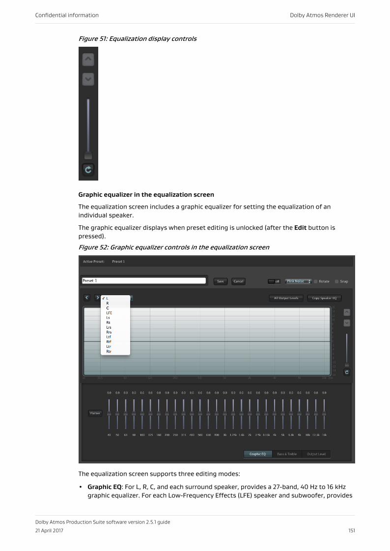
Figure 51: Equalization display controls
Graphic equalizer in the equalization screen
The equalization screen includes a graphic equalizer for setting the equalization of anindividual speaker.
The graphic equalizer displays when preset editing is unlocked (after the Edit button ispressed).
Figure 52: Graphic equalizer controls in the equalization screen
The equalization screen supports three editing modes:
• Graphic EQ: For L, R, C, and each surround speaker, provides a 27-band, 40 Hz to 16 kHzgraphic equalizer. For each Low-Frequency Effects (LFE) speaker and subwoofer, provides
Confidential information Dolby Atmos Renderer UI
Dolby Atmos Production Suite software version 2.5.1 guide
21 April 2017 151
three filters, each with adjustable frequency (Hz), gain (dB), and bandwidth (Q). Gain foreach speaker is –6 to +6 dB.
• Bass & Treble: For L, R, C, and each surround speaker, provides separate bass and treblegain sliders (–6 to +6 dB). For treble only, there are four frequency buttons (1, 2, 3, and 4kHz) to set the frequency where high-frequency shelving begins. The bass and treblecontrols are not available for the subwoofer (LFE) output.
• Output Level: For each speaker, provides a single output-level control. Gain for eachspeaker is –16 to +16 dB.
Each editing mode provides sliders for adjusting level and a Flatten button (to return thesliders to their default value [0 dB]).
Signal generator in the equalization screen
The Renderer includes a signal generator that can generate pink noise and other test tonesignals. Signal can be generated to a specific speaker or to groups of speakers.
The test signals can be very loud and cause damage to hearing or equipment. As an addedsafety measure, signal generator controls are available only when editing is enabled.
The Renderer can generate these signal types:
• Pink Noise
• 100 Hz Sine
• 1 kHz Sine
• 10 kHz Sine
• Thump
• Sweep
The default output level for the pink noise, thump, and sine signal tones is –30 dBFS (whichis the sum of the –20 dB reference level and the pre-EQ –10 dB attenuation). The defaultoutput level for the sweep signal tone is –40 dBFS.
In addition, pink noise can be automatically panned through each channel sequentially, usingtwo operation modes:
• Rotate: Pans signal through each channel sequentially, maintaining a continuous panningvolume. As signal in one channel starts to end, the signal in the next channel begins, suchthat the signals overlap in a smooth fashion.
• Snap: Pans signal through each channel sequentially, one channel at a time, with only onesignal present at any time. After one signal ends, the next signal begins.
The equalization screen provides all signal generator controls, and can be used to generatesignal to a specific speaker, or to pan pink noise through each channel sequentially.
The All Output Levels dialog lets you generate signal to individual speakers.
19.2.9 Room screenIn the room screen, you configure the physical and monitoring layouts for your room.
Confidential information Dolby Atmos Renderer UI
Dolby Atmos Production Suite software version 2.5.1 guide
21 April 2017 152
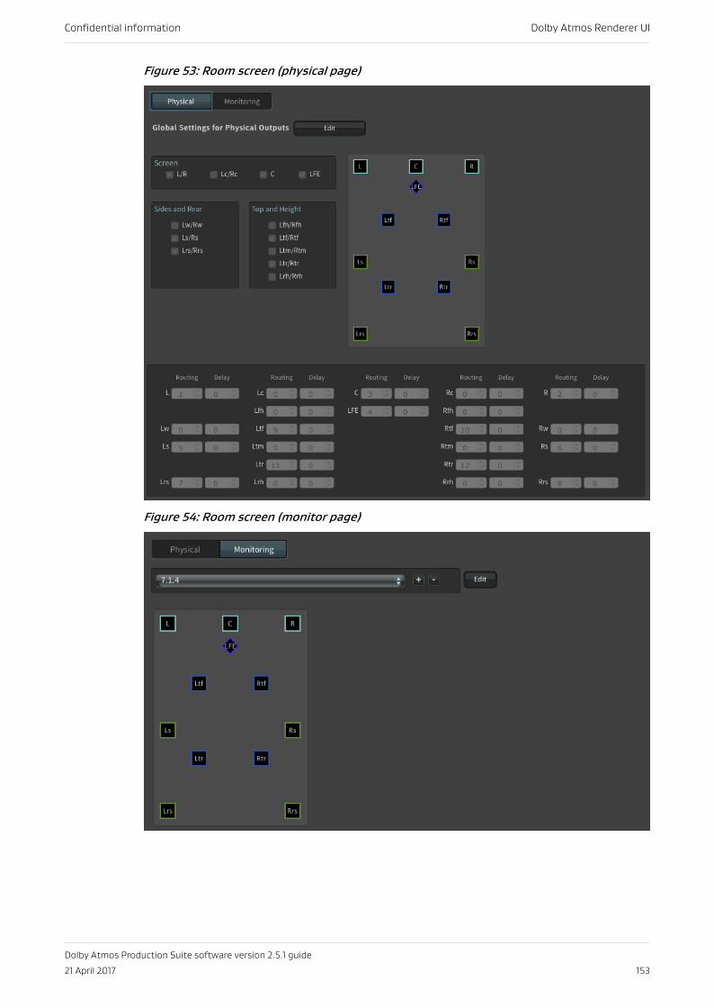
Figure 53: Room screen (physical page)
Figure 54: Room screen (monitor page)
Confidential information Dolby Atmos Renderer UI
Dolby Atmos Production Suite software version 2.5.1 guide
21 April 2017 153
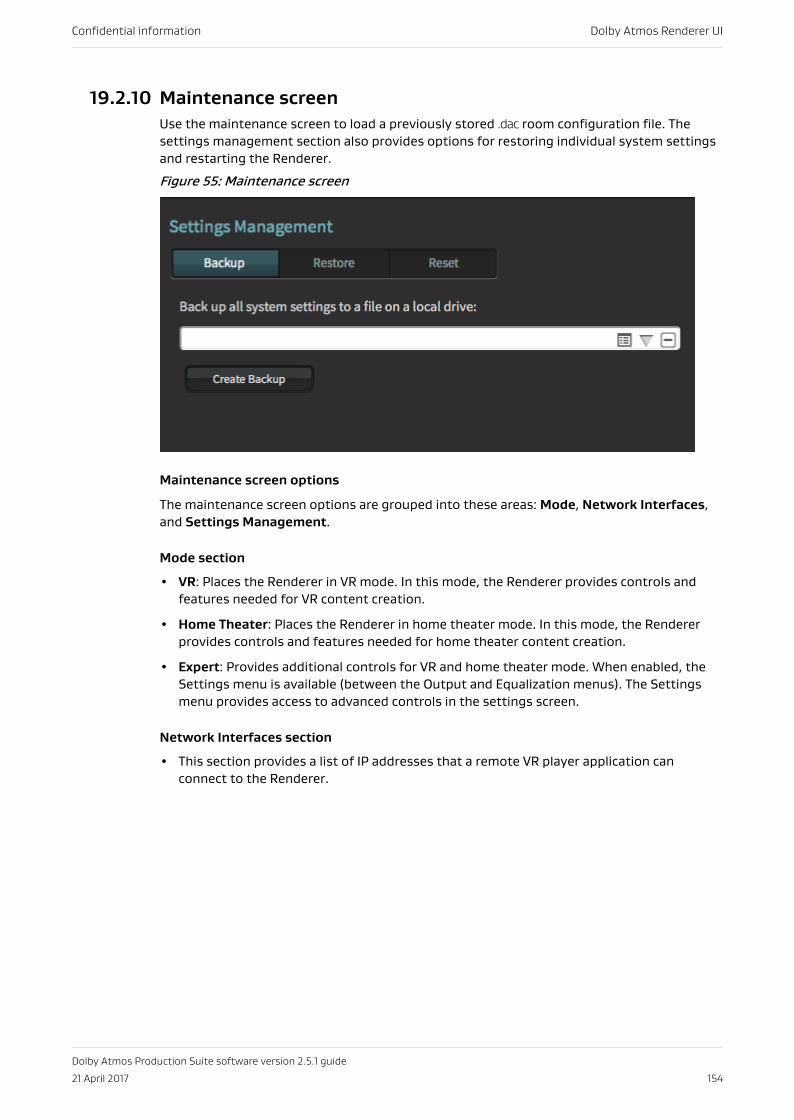
19.2.10 Maintenance screenUse the maintenance screen to load a previously stored .dac room configuration file. Thesettings management section also provides options for restoring individual system settingsand restarting the Renderer.
Figure 55: Maintenance screen
Maintenance screen options
The maintenance screen options are grouped into these areas: Mode, Network Interfaces,and Settings Management.
Mode section
• VR: Places the Renderer in VR mode. In this mode, the Renderer provides controls andfeatures needed for VR content creation.
• Home Theater: Places the Renderer in home theater mode. In this mode, the Rendererprovides controls and features needed for home theater content creation.
• Expert: Provides additional controls for VR and home theater mode. When enabled, theSettings menu is available (between the Output and Equalization menus). The Settingsmenu provides access to advanced controls in the settings screen.
Network Interfaces section
• This section provides a list of IP addresses that a remote VR player application canconnect to the Renderer.
Confidential information Dolby Atmos Renderer UI
Dolby Atmos Production Suite software version 2.5.1 guide
21 April 2017 154
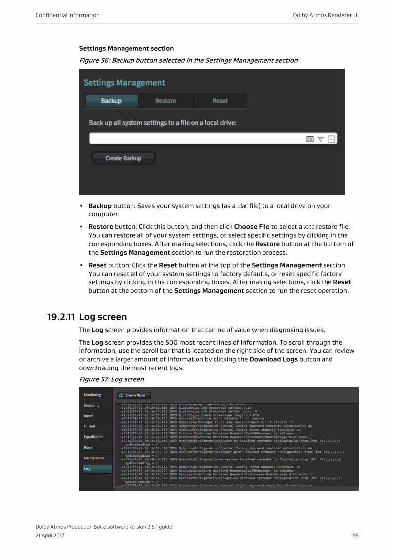
Settings Management section
Figure 56: Backup button selected in the Settings Management section
• Backup button: Saves your system settings (as a .dac file) to a local drive on yourcomputer.
• Restore button: Click this button, and then click Choose File to select a .dac restore file.You can restore all of your system settings, or select specific settings by clicking in thecorresponding boxes. After making selections, click the Restore button at the bottom ofthe Settings Management section to run the restoration process.
• Reset button: Click the Reset button at the top of the Settings Management section.You can reset all of your system settings to factory defaults, or reset specific factorysettings by clicking in the corresponding boxes. After making selections, click the Resetbutton at the bottom of the Settings Management section to run the reset operation.
19.2.11 Log screenThe Log screen provides information that can be of value when diagnosing issues.
The Log screen provides the 500 most recent lines of information. To scroll through theinformation, use the scroll bar that is located on the right side of the screen. You can reviewor archive a larger amount of information by clicking the Download Logs button anddownloading the most recent logs.
Figure 57: Log screen
Confidential information Dolby Atmos Renderer UI
Dolby Atmos Production Suite software version 2.5.1 guide
21 April 2017 155
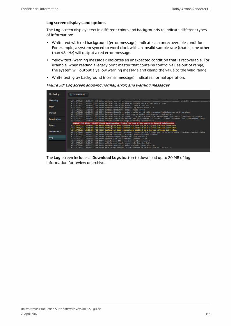
Log screen displays and options
The Log screen displays text in different colors and backgrounds to indicate different typesof information:
• White text with red background (error message): Indicates an unrecoverable condition.For example, a system synced to word clock with an invalid sample rate (that is, one otherthan 48 kHz) will output a red error message.
• Yellow text (warning message): Indicates an unexpected condition that is recoverable. Forexample, when reading a legacy print master that contains control values out of range,the system will output a yellow warning message and clamp the value to the valid range.
• White text, gray background (normal message): Indicates normal operation.
Figure 58: Log screen showing normal, error, and warning messages
The Log screen includes a Download Logs button to download up to 20 MB of loginformation for review or archive.
Confidential information Dolby Atmos Renderer UI
Dolby Atmos Production Suite software version 2.5.1 guide
21 April 2017 156
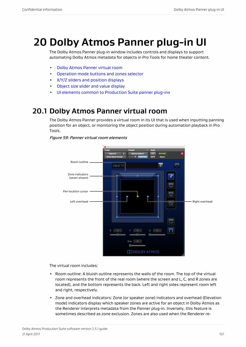
20 Dolby Atmos Panner plug-in UIThe Dolby Atmos Panner plug-in window includes controls and displays to supportautomating Dolby Atmos metadata for objects in Pro Tools for home theater content.
• Dolby Atmos Panner virtual room• Operation mode buttons and zones selector• X/Y/Z sliders and position displays• Object size slider and value display• UI elements common to Production Suite panner plug-ins
20.1 Dolby Atmos Panner virtual roomThe Dolby Atmos Panner provides a virtual room in its UI that is used when inputting panningposition for an object, or monitoring the object position during automation playback in ProTools.
Figure 59: Panner virtual room elements
Right overhead
Zone indicators(seven shown)
Room outline
Pan location cursor
Left overhead
The virtual room includes:
• Room outline: A bluish outline represents the walls of the room. The top of the virtualroom represents the front of the real room (where the screen and L, C, and R zones arelocated), and the bottom represents the back. Left and right sides represent room leftand right, respectively.
• Zone and overhead indicators: Zone (or speaker zone) indicators and overhead (Elevationmode) indicators display which speaker zones are active for an object in Dolby Atmos asthe Renderer interprets metadata from the Panner plug-in. Inversely, this feature issometimes described as zone exclusion. Zones are also used when the Renderer re-
Confidential information Dolby Atmos Panner plug-in UI
Dolby Atmos Production Suite software version 2.5.1 guide
21 April 2017 157
renders the Dolby Atmos mix to a surround format (such as 7.1 or 5.1 channels). You canuse zones to isolate (or dedicate) an object to a specific speaker or group of speakers.Zones are displayed as small blue squares in their relative position. Zones on the roomoutline represent the L, R, C, sides, and rear speaker zones. Six zone configurations areavailable. Zones are active (teal) or inactive (gray), based on the zones button setting.Additionally, two inner blue squares, located on the x-axis, represent the overheads. Theyare active (teal) when Elevation mode or an Elevation Snap mode is on; and inactive (gray)when Elevation mode or an Elevation Snap mode is off.
• Pan location cursor: The pan location cursor provides the current position of the object inthe room. You can move the cursor with a joystick, control surface, mouse, or enabledautomation. The pan location cursor is represented by a yellow dot (located by default atthe center of the virtual room). Depending on the Elevation mode and positioning in theroom, the cursor changes size: the cursor is larger when the object is more elevated, andsmaller when the object is less elevated. As the cursor is moved, the X, Y, and Z slidersand position display values update accordingly. Inversely, the cursor moves when the X,Y, and Z sliders or position display values are adjusted. In Recorder Mode, the cursor isred.
• Object size outline: The outline around the object displays the current spread of its audioin the room. You can set the object size (level of spread) with the Dolby Atmos Pannerplug-in UI, or a control surface, mouse, or enabled automation. The outline changes sizeand direction based on the object size setting and the object position and active speakersin the room.
The color of the area outside of the virtual room indicates the plug-in focus state. Blueindicates the plug-in window (or channel in a stereo plug-in) is focused; gray indicates it isnot. The focused plug-in channel is the one controlled by the joystick.
Panner plug-ins automatically focus when you:
• Open a plug-in window and touch a control (below the plug-in header).
• Open a plug-in window, and click in the plug-in window (below the plug-in header).
Note: Panner plug-ins lose focus when you touch another window or dialog, including aPro Tools control outside of the plug-in (such as setting an Automation mode). Toresume use of Panner plug-in controls, refocus the plug-in.
20.2 Operation mode buttons and zones selectorThe Panner plug-in window includes buttons and selectors for enabling or selecting commonoperation modes and displaying their status.
Elevation mode button:This button toggles Elevation mode on and off. Elevation mode allows for manualadjustment of the z (top/bottom) dimension in the virtual room. When Elevation mode isoff, you cannot adjust the z coordinate, but previously written manual adjustments canbe read.
Elevation Snap mode buttons:These buttons let you toggle an Elevation Snap mode on or off, in order to change theshape of the ceiling in the room, and in turn, how elevation drops as objects are pannedaway from the ceiling.
Speaker Snap mode button:This button toggles Speaker Snap mode on and off. Speaker Snap mode moves objectaudio to the active speaker nearest its established location during playback (for example,to eliminate phantom panning). At the Renderer, this ensures that 100% of the audio
Confidential information Dolby Atmos Panner plug-in UI
Dolby Atmos Production Suite software version 2.5.1 guide
21 April 2017 158
signal is routed to the single speaker that is nearest to the current spatial placement.Speaker Snap mode does not move the pan location cursor in the virtual room.
Zones selector:This selector lets you select one of six common speaker zone layouts, in order to activateor deactivate specific speaker zones (for example, to isolate or dedicate an object to aspecific group of speakers).
20.3 X/Y/Z sliders and position displaysThe X/Y/Z sliders and displays let you adjust the location of an object in the virtual room,through all three dimensions: x (left/right), y (front/back), and z (top/bottom).
• X: Lets you control the left and right position of an object. The X range is –100 to 100. Thedefault is 0.
• Y: Lets you control the front and back position of an object. The Y: range is –100 to 100.The default is 0.
• Z: Lets you control the height (top and bottom) position of an object. The Z range is 0 to100. The default is 0.
Note: The Dolby Atmos VR XYZ Panner plug-in does not include Elevation mode,Elevation Snap mode, and Speaker Snap mode buttons, a Zones selector, or a Size sliderand display. These features are not supported with VR.
20.3.1 Elevation and Z coordinate user-interface elementsIn all Elevation modes or an Elevation Snap mode, the Z slider position, its display value, andthe z automation playlist match as expected.
These elements always represent the overhead level that is displayed in both the plug-in UI,and the Monitor application. However, there are situations where the rendered audio outputmay not match the z position being displayed. For example, if you disable Elevation modeafter writing z automation, audio will play back rendered without overheads, but the plug-inUI will continue to display the z automation.
There are also situations where the z automation UI and rendered audio output do notupdate during a write automation pass as expected. If you enable an Elevation Snap modeduring a write automation pass, the z automation and elevation amount will not update untilnew automation data for the corresponding slider is written. For example, when you enableSphere Elevation Snap mode, updates occur after new x or y automation data is written.
Note: After authoring Panner plug-in automation with Elevation mode or an ElevationSnap mode on, you can edit the z automation data that was recorded by using a penciltool in the z automation playlist. The elevation defined by the new automation will beapplied to the rendered object audio in the subsequent playback as long as Elevationmode is enabled.
20.4 Object size slider and value displayThe Object Size slider lets you spread audio for an object across the room, based on thecurrent object position and active speakers in the room.
You can use a joystick, control surface, mouse, enabled automation, or keyboard to adjustthe size (or spread). The object size outline, which surrounds the object cursor in the virtualroom, shows the current spread for an object. The object size has a range of 0 to 100.
Confidential information Dolby Atmos Panner plug-in UI
Dolby Atmos Production Suite software version 2.5.1 guide
21 April 2017 159
Use object size to increase or decrease the number of loudspeakers used to render aparticular object.
Object size spreads the audio for an object, as follows:
• At 0, object size is effectively off, and audio routes to speakers based on the x/y/zposition or Speaker Snap mode.
• At 100, audio spreads to all active speakers, regardless of the location of the cursor.
• For values between 0 and 100, spreading is based on the object size, the object location,and the number of active speakers.
Note: Object size is disabled when Speaker Snap mode is on.
Note: When using values between 50 and 100, audio may spread to all active speakers,regardless of the location of the cursor. For example, if you have an object in the centerof the room, with size = 51, it is effectively the same as an object in the corner of theroom with size = 100. Play with the object size control starting from different roomlocations to see how object size spreads audio.
Confidential information Dolby Atmos Panner plug-in UI
Dolby Atmos Production Suite software version 2.5.1 guide
21 April 2017 160
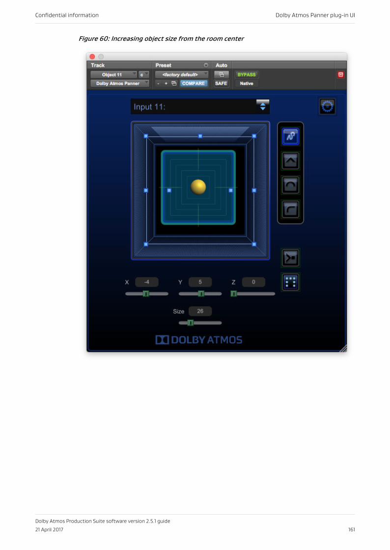
Figure 60: Increasing object size from the room center
Confidential information Dolby Atmos Panner plug-in UI
Dolby Atmos Production Suite software version 2.5.1 guide
21 April 2017 161
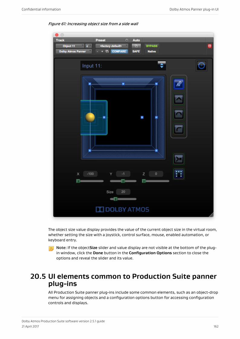
Figure 61: Increasing object size from a side wall
The object size value display provides the value of the current object size in the virtual room,whether setting the size with a joystick, control surface, mouse, enabled automation, orkeyboard entry.
Note: If the objectSize slider and value display are not visible at the bottom of the plug-in window, click the Done button in the Configuration Options section to close theoptions and reveal the slider and its value.
20.5 UI elements common to Production Suite pannerplug-insAll Production Suite panner plug-ins include some common elements, such as an object-dropmenu for assigning objects and a configuration options button for accessing configurationcontrols and displays.
Confidential information Dolby Atmos Panner plug-in UI
Dolby Atmos Production Suite software version 2.5.1 guide
21 April 2017 162
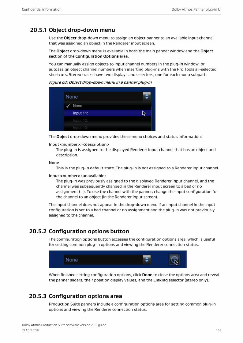
20.5.1 Object drop-down menuUse the Object drop-down menu to assign an object panner to an available input channelthat was assigned an object in the Renderer input screen.
The Object drop-down menu is available in both the main panner window and the Objectsection of the Configuration Options area.
You can manually assign objects to input channel numbers in the plug-in window, orautoassign object channel numbers when inserting plug-ins with the Pro Tools all-selectedshortcuts. Stereo tracks have two displays and selectors, one for each mono subpath.
Figure 62: Object drop-down menu in a panner plug-in
The Object drop-down menu provides these menu choices and status information:
Input <number>: <description>The plug-in is assigned to the displayed Renderer input channel that has an object anddescription.
NoneThis is the plug-in default state. The plug-in is not assigned to a Renderer input channel.
Input <number> (unavailable)The plug-in was previously assigned to the displayed Renderer input channel, and thechannel was subsequently changed in the Renderer input screen to a bed or noassignment (--). To use the channel with the panner, change the input configuration forthe channel to an object (in the Renderer input screen).
The input channel does not appear in the drop-down menu if an input channel in the inputconfiguration is set to a bed channel or no assignment and the plug-in was not previouslyassigned to the channel.
20.5.2 Configuration options buttonThe configuration options button accesses the configuration options area, which is usefulfor setting common plug-in options and viewing the Renderer connection status.
When finished setting configuration options, click Done to close the options area and revealthe panner sliders, their position display values, and the Linking selector (stereo only).
20.5.3 Configuration options areaProduction Suite panners include a configuration options area for setting common plug-inoptions and viewing the Renderer connection status.
Confidential information Dolby Atmos Panner plug-in UI
Dolby Atmos Production Suite software version 2.5.1 guide
21 April 2017 163
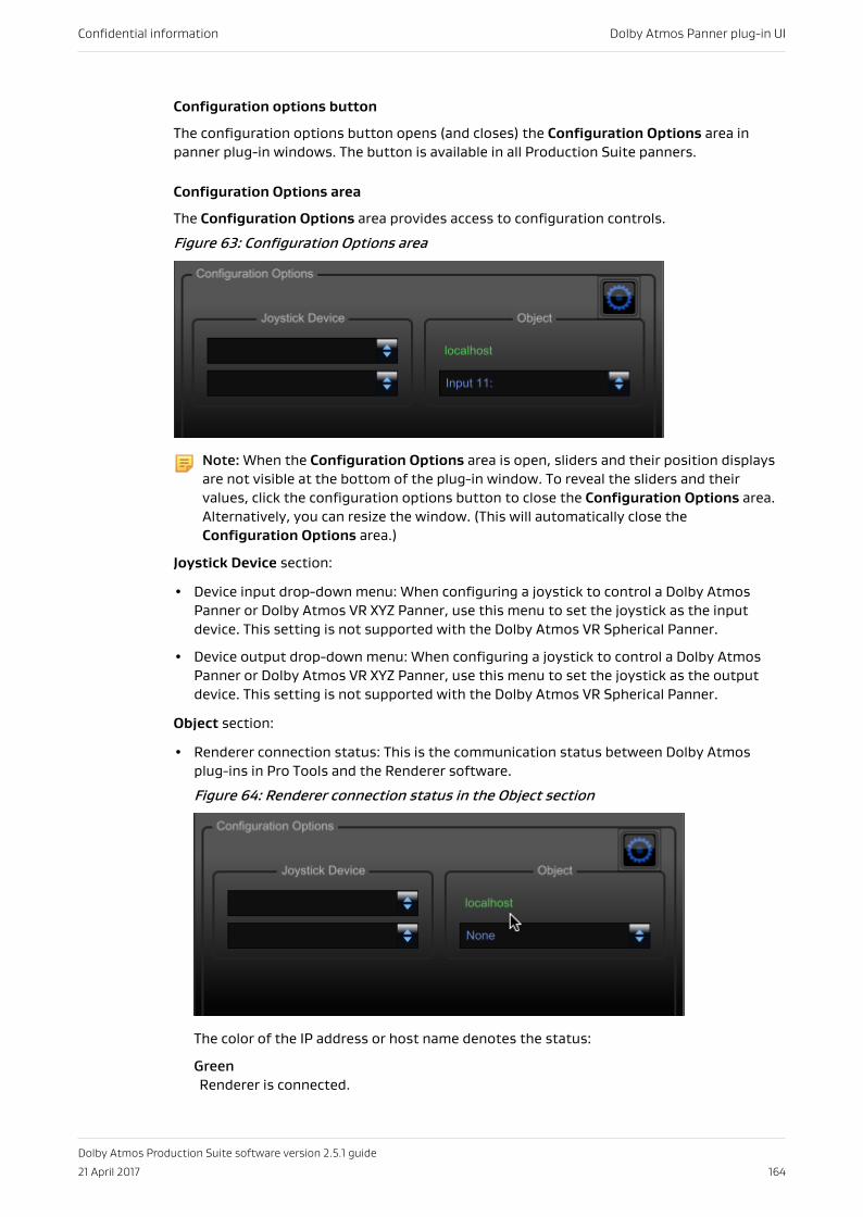
Configuration options button
The configuration options button opens (and closes) the Configuration Options area inpanner plug-in windows. The button is available in all Production Suite panners.
Configuration Options area
The Configuration Options area provides access to configuration controls.
Figure 63: Configuration Options area
Note: When the Configuration Options area is open, sliders and their position displaysare not visible at the bottom of the plug-in window. To reveal the sliders and theirvalues, click the configuration options button to close the Configuration Options area.Alternatively, you can resize the window. (This will automatically close theConfiguration Options area.)
Joystick Device section:
• Device input drop-down menu: When configuring a joystick to control a Dolby AtmosPanner or Dolby Atmos VR XYZ Panner, use this menu to set the joystick as the inputdevice. This setting is not supported with the Dolby Atmos VR Spherical Panner.
• Device output drop-down menu: When configuring a joystick to control a Dolby AtmosPanner or Dolby Atmos VR XYZ Panner, use this menu to set the joystick as the outputdevice. This setting is not supported with the Dolby Atmos VR Spherical Panner.
Object section:
• Renderer connection status: This is the communication status between Dolby Atmosplug-ins in Pro Tools and the Renderer software.
Figure 64: Renderer connection status in the Object section
The color of the IP address or host name denotes the status:
GreenRenderer is connected.
Confidential information Dolby Atmos Panner plug-in UI
Dolby Atmos Production Suite software version 2.5.1 guide
21 April 2017 164
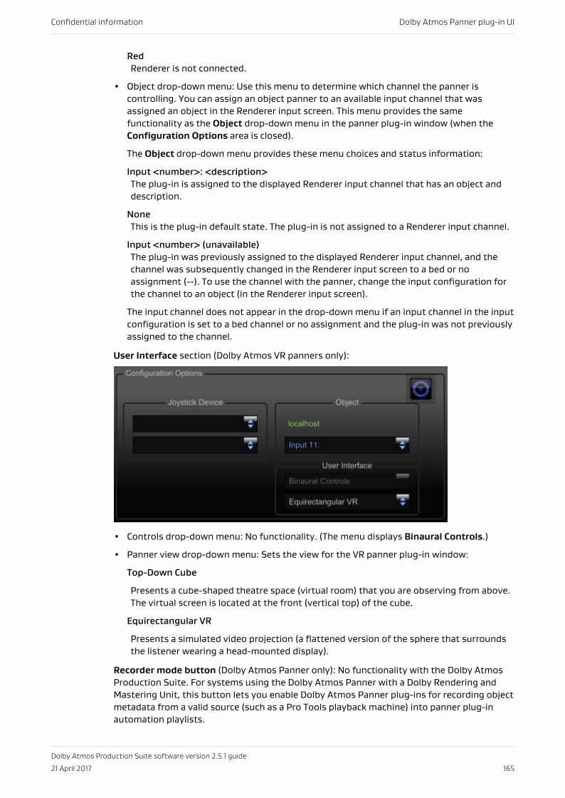
RedRenderer is not connected.
• Object drop-down menu: Use this menu to determine which channel the panner iscontrolling. You can assign an object panner to an available input channel that wasassigned an object in the Renderer input screen. This menu provides the samefunctionality as the Object drop-down menu in the panner plug-in window (when theConfiguration Options area is closed).
The Object drop-down menu provides these menu choices and status information:
Input <number>: <description>The plug-in is assigned to the displayed Renderer input channel that has an object anddescription.
NoneThis is the plug-in default state. The plug-in is not assigned to a Renderer input channel.
Input <number> (unavailable)The plug-in was previously assigned to the displayed Renderer input channel, and thechannel was subsequently changed in the Renderer input screen to a bed or noassignment (--). To use the channel with the panner, change the input configuration forthe channel to an object (in the Renderer input screen).
The input channel does not appear in the drop-down menu if an input channel in the inputconfiguration is set to a bed channel or no assignment and the plug-in was not previouslyassigned to the channel.
User Interface section (Dolby Atmos VR panners only):
• Controls drop-down menu: No functionality. (The menu displays Binaural Controls.)
• Panner view drop-down menu: Sets the view for the VR panner plug-in window:
Top-Down Cube
Presents a cube-shaped theatre space (virtual room) that you are observing from above.The virtual screen is located at the front (vertical top) of the cube.
Equirectangular VR
Presents a simulated video projection (a flattened version of the sphere that surroundsthe listener wearing a head-mounted display).
Recorder mode button (Dolby Atmos Panner only): No functionality with the Dolby AtmosProduction Suite. For systems using the Dolby Atmos Panner with a Dolby Rendering andMastering Unit, this button lets you enable Dolby Atmos Panner plug-ins for recording objectmetadata from a valid source (such as a Pro Tools playback machine) into panner plug-inautomation playlists.
Confidential information Dolby Atmos Panner plug-in UI
Dolby Atmos Production Suite software version 2.5.1 guide
21 April 2017 165
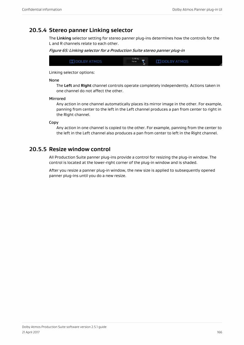
20.5.4 Stereo panner Linking selectorThe Linking selector setting for stereo panner plug-ins determines how the controls for theL and R channels relate to each other.
Figure 65: Linking selector for a Production Suite stereo panner plug-in
Linking selector options:
NoneThe Left and Right channel controls operate completely independently. Actions taken inone channel do not affect the other.
MirroredAny action in one channel automatically places its mirror image in the other. For example,panning from center to the left in the Left channel produces a pan from center to right inthe Right channel.
CopyAny action in one channel is copied to the other. For example, panning from the center tothe left in the Left channel also produces a pan from center to left in the Right channel.
20.5.5 Resize window controlAll Production Suite panner plug-ins provide a control for resizing the plug-in window. Thecontrol is located at the lower-right corner of the plug-in window and is shaded.
After you resize a panner plug-in window, the new size is applied to subsequently openedpanner plug-ins until you do a new resize.
Confidential information Dolby Atmos Panner plug-in UI
Dolby Atmos Production Suite software version 2.5.1 guide
21 April 2017 166
21 Dolby Atmos VR Spherical Pannerplug-in UIThe Dolby Atmos VR Spherical Panner plug-in window includes controls and displays tosupport automating Dolby Atmos metadata for objects using a polar coordinate system.
• Dolby Atmos VR Spherical Panner views• Binaural and head-tracking controls• θ/φ/ρ spherical sliders and position displays• UI elements common to Production Suite panner plug-ins
21.1 Dolby Atmos VR Spherical Panner viewsThe Dolby Atmos VR Spherical Panner plug-in window provides controls and displays in twodifferent views: equirectangular VR view and top-down cube view.
You set the panner view in the User Interface section of the Configuration Options.
Equirectangular VR viewThis view presents a simulated video projection (a flattened version of the sphere thatsurrounds the listener wearing a head-mounted display). This is the default view for theDolby Atmos VR Spherical Panner.
Confidential information Dolby Atmos VR Spherical Panner plug-in UI
Dolby Atmos Production Suite software version 2.5.1 guide
21 April 2017 167
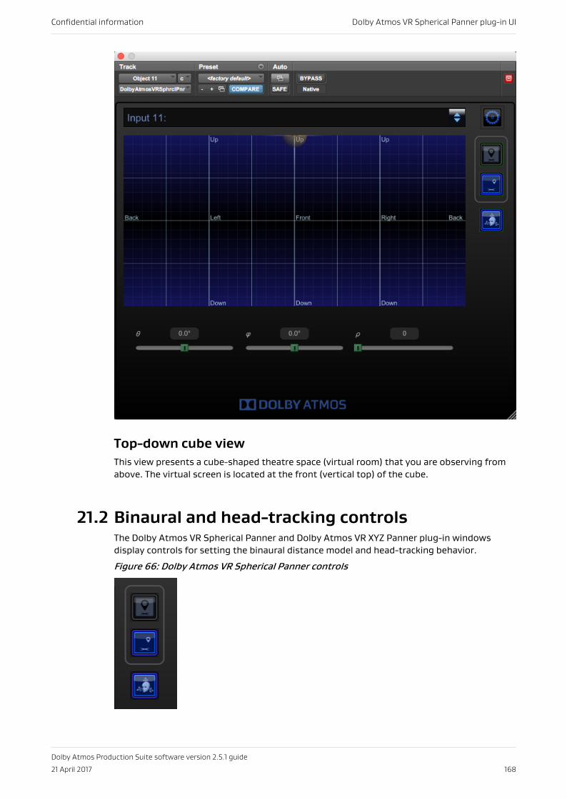
Top-down cube viewThis view presents a cube-shaped theatre space (virtual room) that you are observing fromabove. The virtual screen is located at the front (vertical top) of the cube.
21.2 Binaural and head-tracking controlsThe Dolby Atmos VR Spherical Panner and Dolby Atmos VR XYZ Panner plug-in windowsdisplay controls for setting the binaural distance model and head-tracking behavior.
Figure 66: Dolby Atmos VR Spherical Panner controls
Confidential information Dolby Atmos VR Spherical Panner plug-in UI
Dolby Atmos Production Suite software version 2.5.1 guide
21 April 2017 168
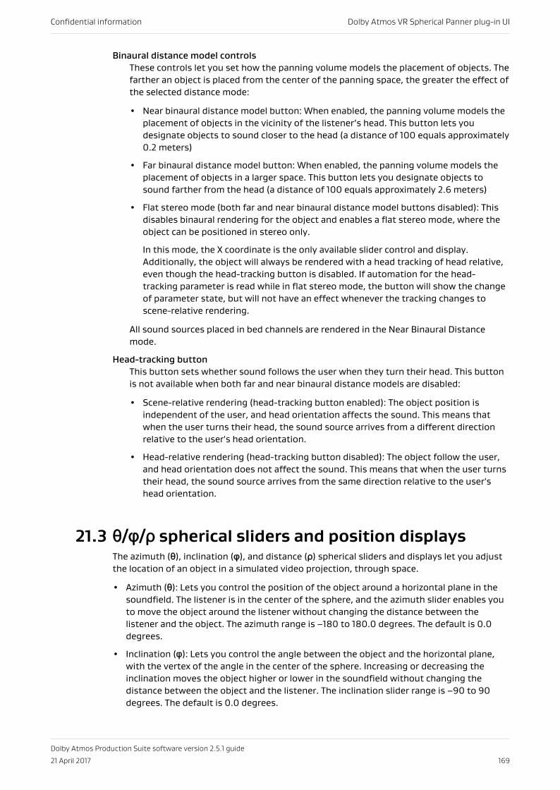
Binaural distance model controlsThese controls let you set how the panning volume models the placement of objects. Thefarther an object is placed from the center of the panning space, the greater the effect ofthe selected distance mode:
• Near binaural distance model button: When enabled, the panning volume models theplacement of objects in the vicinity of the listener’s head. This button lets youdesignate objects to sound closer to the head (a distance of 100 equals approximately0.2 meters)
• Far binaural distance model button: When enabled, the panning volume models theplacement of objects in a larger space. This button lets you designate objects tosound farther from the head (a distance of 100 equals approximately 2.6 meters)
• Flat stereo mode (both far and near binaural distance model buttons disabled): Thisdisables binaural rendering for the object and enables a flat stereo mode, where theobject can be positioned in stereo only.
In this mode, the X coordinate is the only available slider control and display.Additionally, the object will always be rendered with a head tracking of head relative,even though the head-tracking button is disabled. If automation for the head-tracking parameter is read while in flat stereo mode, the button will show the changeof parameter state, but will not have an effect whenever the tracking changes toscene-relative rendering.
All sound sources placed in bed channels are rendered in the Near Binaural Distancemode.
Head-tracking buttonThis button sets whether sound follows the user when they turn their head. This buttonis not available when both far and near binaural distance models are disabled:
• Scene-relative rendering (head-tracking button enabled): The object position isindependent of the user, and head orientation affects the sound. This means thatwhen the user turns their head, the sound source arrives from a different directionrelative to the user's head orientation.
• Head-relative rendering (head-tracking button disabled): The object follow the user,and head orientation does not affect the sound. This means that when the user turnstheir head, the sound source arrives from the same direction relative to the user'shead orientation.
21.3 θ/φ/ρ spherical sliders and position displaysThe azimuth (θ), inclination (φ), and distance (ρ) spherical sliders and displays let you adjustthe location of an object in a simulated video projection, through space.
• Azimuth (θ): Lets you control the position of the object around a horizontal plane in thesoundfield. The listener is in the center of the sphere, and the azimuth slider enables youto move the object around the listener without changing the distance between thelistener and the object. The azimuth range is –180 to 180.0 degrees. The default is 0.0degrees.
• Inclination (φ): Lets you control the angle between the object and the horizontal plane,with the vertex of the angle in the center of the sphere. Increasing or decreasing theinclination moves the object higher or lower in the soundfield without changing thedistance between the object and the listener. The inclination slider range is –90 to 90degrees. The default is 0.0 degrees.
Confidential information Dolby Atmos VR Spherical Panner plug-in UI
Dolby Atmos Production Suite software version 2.5.1 guide
21 April 2017 169
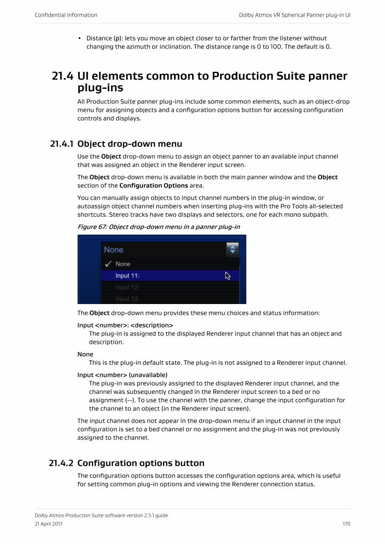
• Distance (ρ): lets you move an object closer to or farther from the listener withoutchanging the azimuth or inclination. The distance range is 0 to 100. The default is 0.
21.4 UI elements common to Production Suite pannerplug-insAll Production Suite panner plug-ins include some common elements, such as an object-dropmenu for assigning objects and a configuration options button for accessing configurationcontrols and displays.
21.4.1 Object drop-down menuUse the Object drop-down menu to assign an object panner to an available input channelthat was assigned an object in the Renderer input screen.
The Object drop-down menu is available in both the main panner window and the Objectsection of the Configuration Options area.
You can manually assign objects to input channel numbers in the plug-in window, orautoassign object channel numbers when inserting plug-ins with the Pro Tools all-selectedshortcuts. Stereo tracks have two displays and selectors, one for each mono subpath.
Figure 67: Object drop-down menu in a panner plug-in
The Object drop-down menu provides these menu choices and status information:
Input <number>: <description>The plug-in is assigned to the displayed Renderer input channel that has an object anddescription.
NoneThis is the plug-in default state. The plug-in is not assigned to a Renderer input channel.
Input <number> (unavailable)The plug-in was previously assigned to the displayed Renderer input channel, and thechannel was subsequently changed in the Renderer input screen to a bed or noassignment (--). To use the channel with the panner, change the input configuration forthe channel to an object (in the Renderer input screen).
The input channel does not appear in the drop-down menu if an input channel in the inputconfiguration is set to a bed channel or no assignment and the plug-in was not previouslyassigned to the channel.
21.4.2 Configuration options buttonThe configuration options button accesses the configuration options area, which is usefulfor setting common plug-in options and viewing the Renderer connection status.
Confidential information Dolby Atmos VR Spherical Panner plug-in UI
Dolby Atmos Production Suite software version 2.5.1 guide
21 April 2017 170
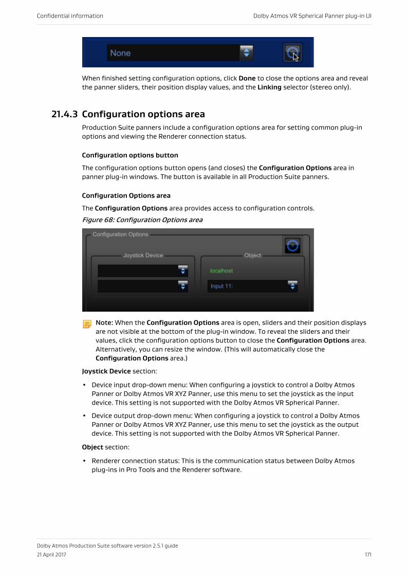
When finished setting configuration options, click Done to close the options area and revealthe panner sliders, their position display values, and the Linking selector (stereo only).
21.4.3 Configuration options areaProduction Suite panners include a configuration options area for setting common plug-inoptions and viewing the Renderer connection status.
Configuration options button
The configuration options button opens (and closes) the Configuration Options area inpanner plug-in windows. The button is available in all Production Suite panners.
Configuration Options area
The Configuration Options area provides access to configuration controls.
Figure 68: Configuration Options area
Note: When the Configuration Options area is open, sliders and their position displaysare not visible at the bottom of the plug-in window. To reveal the sliders and theirvalues, click the configuration options button to close the Configuration Options area.Alternatively, you can resize the window. (This will automatically close theConfiguration Options area.)
Joystick Device section:
• Device input drop-down menu: When configuring a joystick to control a Dolby AtmosPanner or Dolby Atmos VR XYZ Panner, use this menu to set the joystick as the inputdevice. This setting is not supported with the Dolby Atmos VR Spherical Panner.
• Device output drop-down menu: When configuring a joystick to control a Dolby AtmosPanner or Dolby Atmos VR XYZ Panner, use this menu to set the joystick as the outputdevice. This setting is not supported with the Dolby Atmos VR Spherical Panner.
Object section:
• Renderer connection status: This is the communication status between Dolby Atmosplug-ins in Pro Tools and the Renderer software.
Confidential information Dolby Atmos VR Spherical Panner plug-in UI
Dolby Atmos Production Suite software version 2.5.1 guide
21 April 2017 171
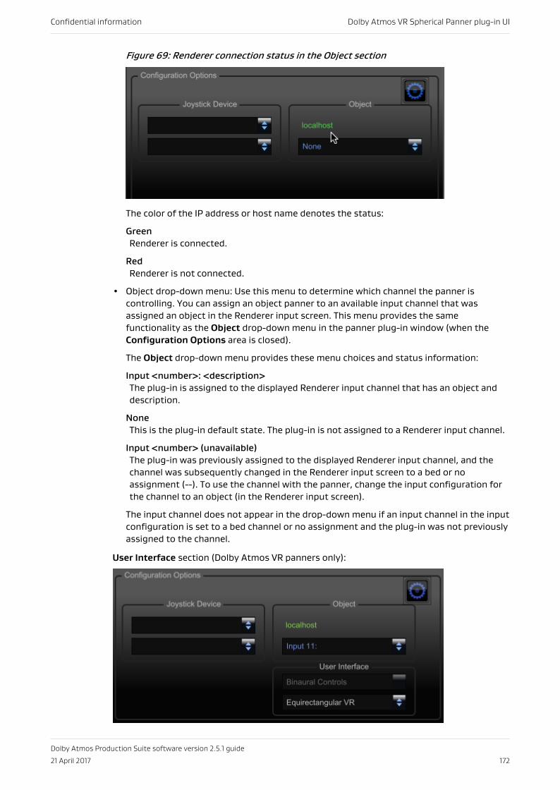
Figure 69: Renderer connection status in the Object section
The color of the IP address or host name denotes the status:
GreenRenderer is connected.
RedRenderer is not connected.
• Object drop-down menu: Use this menu to determine which channel the panner iscontrolling. You can assign an object panner to an available input channel that wasassigned an object in the Renderer input screen. This menu provides the samefunctionality as the Object drop-down menu in the panner plug-in window (when theConfiguration Options area is closed).
The Object drop-down menu provides these menu choices and status information:
Input <number>: <description>The plug-in is assigned to the displayed Renderer input channel that has an object anddescription.
NoneThis is the plug-in default state. The plug-in is not assigned to a Renderer input channel.
Input <number> (unavailable)The plug-in was previously assigned to the displayed Renderer input channel, and thechannel was subsequently changed in the Renderer input screen to a bed or noassignment (--). To use the channel with the panner, change the input configuration forthe channel to an object (in the Renderer input screen).
The input channel does not appear in the drop-down menu if an input channel in the inputconfiguration is set to a bed channel or no assignment and the plug-in was not previouslyassigned to the channel.
User Interface section (Dolby Atmos VR panners only):
Confidential information Dolby Atmos VR Spherical Panner plug-in UI
Dolby Atmos Production Suite software version 2.5.1 guide
21 April 2017 172
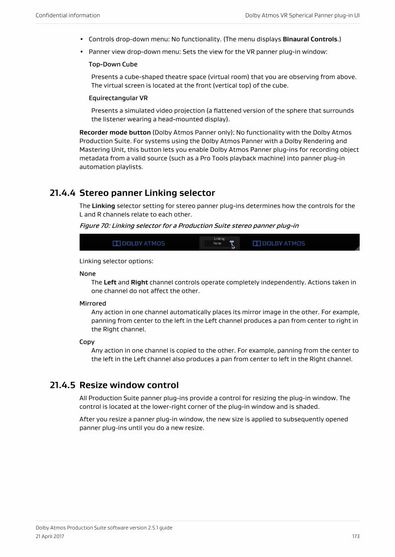
• Controls drop-down menu: No functionality. (The menu displays Binaural Controls.)
• Panner view drop-down menu: Sets the view for the VR panner plug-in window:
Top-Down Cube
Presents a cube-shaped theatre space (virtual room) that you are observing from above.The virtual screen is located at the front (vertical top) of the cube.
Equirectangular VR
Presents a simulated video projection (a flattened version of the sphere that surroundsthe listener wearing a head-mounted display).
Recorder mode button (Dolby Atmos Panner only): No functionality with the Dolby AtmosProduction Suite. For systems using the Dolby Atmos Panner with a Dolby Rendering andMastering Unit, this button lets you enable Dolby Atmos Panner plug-ins for recording objectmetadata from a valid source (such as a Pro Tools playback machine) into panner plug-inautomation playlists.
21.4.4 Stereo panner Linking selectorThe Linking selector setting for stereo panner plug-ins determines how the controls for theL and R channels relate to each other.
Figure 70: Linking selector for a Production Suite stereo panner plug-in
Linking selector options:
NoneThe Left and Right channel controls operate completely independently. Actions taken inone channel do not affect the other.
MirroredAny action in one channel automatically places its mirror image in the other. For example,panning from center to the left in the Left channel produces a pan from center to right inthe Right channel.
CopyAny action in one channel is copied to the other. For example, panning from the center tothe left in the Left channel also produces a pan from center to left in the Right channel.
21.4.5 Resize window controlAll Production Suite panner plug-ins provide a control for resizing the plug-in window. Thecontrol is located at the lower-right corner of the plug-in window and is shaded.
After you resize a panner plug-in window, the new size is applied to subsequently openedpanner plug-ins until you do a new resize.
Confidential information Dolby Atmos VR Spherical Panner plug-in UI
Dolby Atmos Production Suite software version 2.5.1 guide
21 April 2017 173
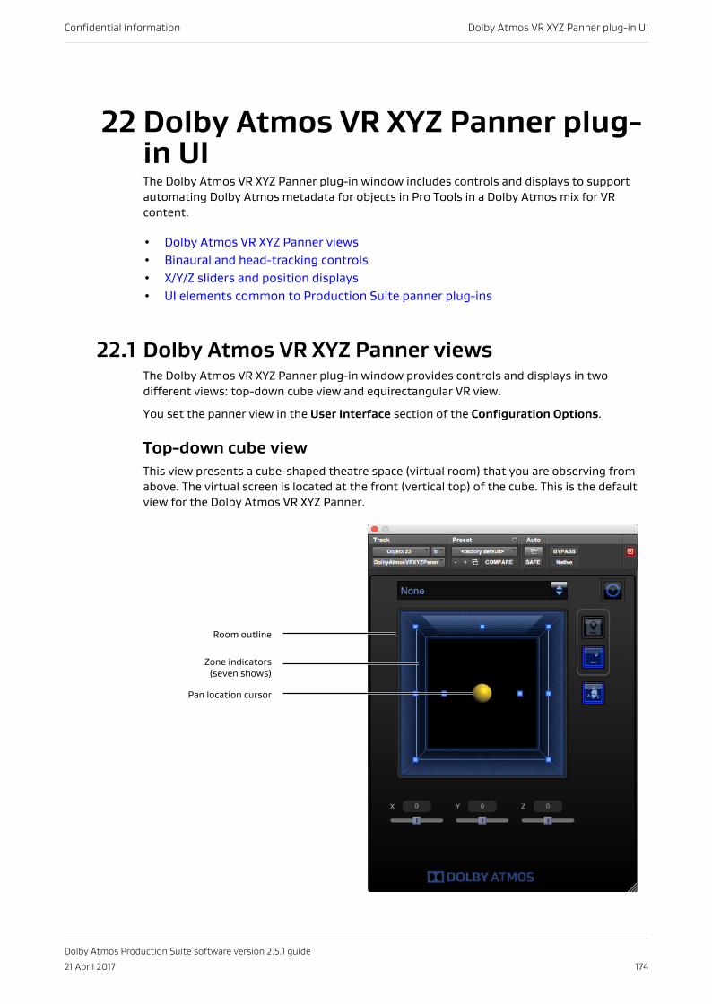
22 Dolby Atmos VR XYZ Panner plug-in UIThe Dolby Atmos VR XYZ Panner plug-in window includes controls and displays to supportautomating Dolby Atmos metadata for objects in Pro Tools in a Dolby Atmos mix for VRcontent.
• Dolby Atmos VR XYZ Panner views• Binaural and head-tracking controls• X/Y/Z sliders and position displays• UI elements common to Production Suite panner plug-ins
22.1 Dolby Atmos VR XYZ Panner viewsThe Dolby Atmos VR XYZ Panner plug-in window provides controls and displays in twodifferent views: top-down cube view and equirectangular VR view.
You set the panner view in the User Interface section of the Configuration Options.
Top-down cube viewThis view presents a cube-shaped theatre space (virtual room) that you are observing fromabove. The virtual screen is located at the front (vertical top) of the cube. This is the defaultview for the Dolby Atmos VR XYZ Panner.
Room outline
Zone indicators(seven shows)
Pan location cursor
Confidential information Dolby Atmos VR XYZ Panner plug-in UI
Dolby Atmos Production Suite software version 2.5.1 guide
21 April 2017 174
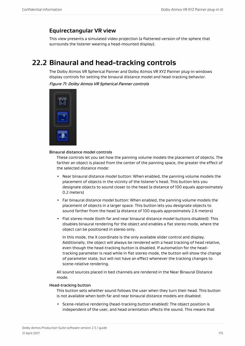
Equirectangular VR viewThis view presents a simulated video projection (a flattened version of the sphere thatsurrounds the listener wearing a head-mounted display).
22.2 Binaural and head-tracking controlsThe Dolby Atmos VR Spherical Panner and Dolby Atmos VR XYZ Panner plug-in windowsdisplay controls for setting the binaural distance model and head-tracking behavior.
Figure 71: Dolby Atmos VR Spherical Panner controls
Binaural distance model controlsThese controls let you set how the panning volume models the placement of objects. Thefarther an object is placed from the center of the panning space, the greater the effect ofthe selected distance mode:
• Near binaural distance model button: When enabled, the panning volume models theplacement of objects in the vicinity of the listener’s head. This button lets youdesignate objects to sound closer to the head (a distance of 100 equals approximately0.2 meters)
• Far binaural distance model button: When enabled, the panning volume models theplacement of objects in a larger space. This button lets you designate objects tosound farther from the head (a distance of 100 equals approximately 2.6 meters)
• Flat stereo mode (both far and near binaural distance model buttons disabled): Thisdisables binaural rendering for the object and enables a flat stereo mode, where theobject can be positioned in stereo only.
In this mode, the X coordinate is the only available slider control and display.Additionally, the object will always be rendered with a head tracking of head relative,even though the head-tracking button is disabled. If automation for the head-tracking parameter is read while in flat stereo mode, the button will show the changeof parameter state, but will not have an effect whenever the tracking changes toscene-relative rendering.
All sound sources placed in bed channels are rendered in the Near Binaural Distancemode.
Head-tracking buttonThis button sets whether sound follows the user when they turn their head. This buttonis not available when both far and near binaural distance models are disabled:
• Scene-relative rendering (head-tracking button enabled): The object position isindependent of the user, and head orientation affects the sound. This means that
Confidential information Dolby Atmos VR XYZ Panner plug-in UI
Dolby Atmos Production Suite software version 2.5.1 guide
21 April 2017 175
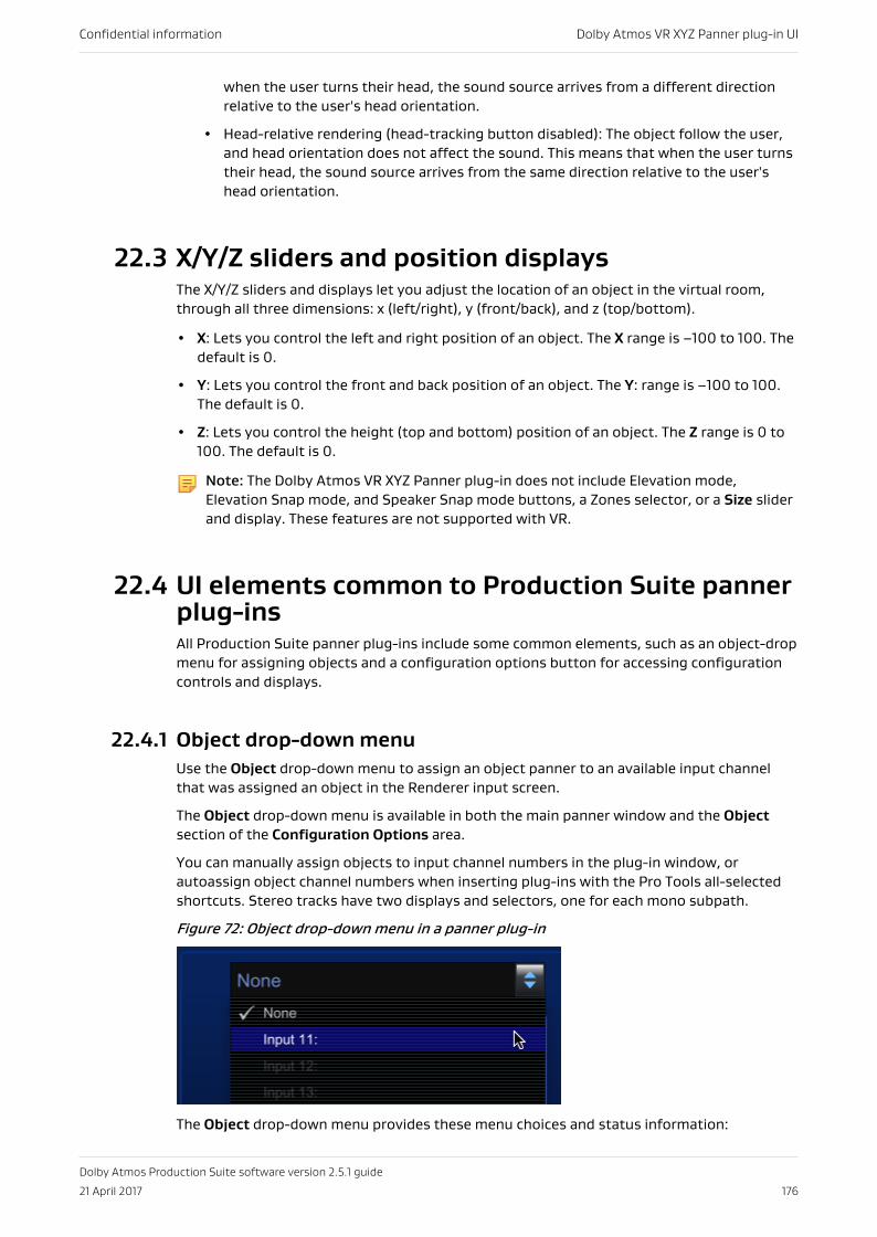
when the user turns their head, the sound source arrives from a different directionrelative to the user's head orientation.
• Head-relative rendering (head-tracking button disabled): The object follow the user,and head orientation does not affect the sound. This means that when the user turnstheir head, the sound source arrives from the same direction relative to the user'shead orientation.
22.3 X/Y/Z sliders and position displaysThe X/Y/Z sliders and displays let you adjust the location of an object in the virtual room,through all three dimensions: x (left/right), y (front/back), and z (top/bottom).
• X: Lets you control the left and right position of an object. The X range is –100 to 100. Thedefault is 0.
• Y: Lets you control the front and back position of an object. The Y: range is –100 to 100.The default is 0.
• Z: Lets you control the height (top and bottom) position of an object. The Z range is 0 to100. The default is 0.
Note: The Dolby Atmos VR XYZ Panner plug-in does not include Elevation mode,Elevation Snap mode, and Speaker Snap mode buttons, a Zones selector, or a Size sliderand display. These features are not supported with VR.
22.4 UI elements common to Production Suite pannerplug-insAll Production Suite panner plug-ins include some common elements, such as an object-dropmenu for assigning objects and a configuration options button for accessing configurationcontrols and displays.
22.4.1 Object drop-down menuUse the Object drop-down menu to assign an object panner to an available input channelthat was assigned an object in the Renderer input screen.
The Object drop-down menu is available in both the main panner window and the Objectsection of the Configuration Options area.
You can manually assign objects to input channel numbers in the plug-in window, orautoassign object channel numbers when inserting plug-ins with the Pro Tools all-selectedshortcuts. Stereo tracks have two displays and selectors, one for each mono subpath.
Figure 72: Object drop-down menu in a panner plug-in
The Object drop-down menu provides these menu choices and status information:
Confidential information Dolby Atmos VR XYZ Panner plug-in UI
Dolby Atmos Production Suite software version 2.5.1 guide
21 April 2017 176
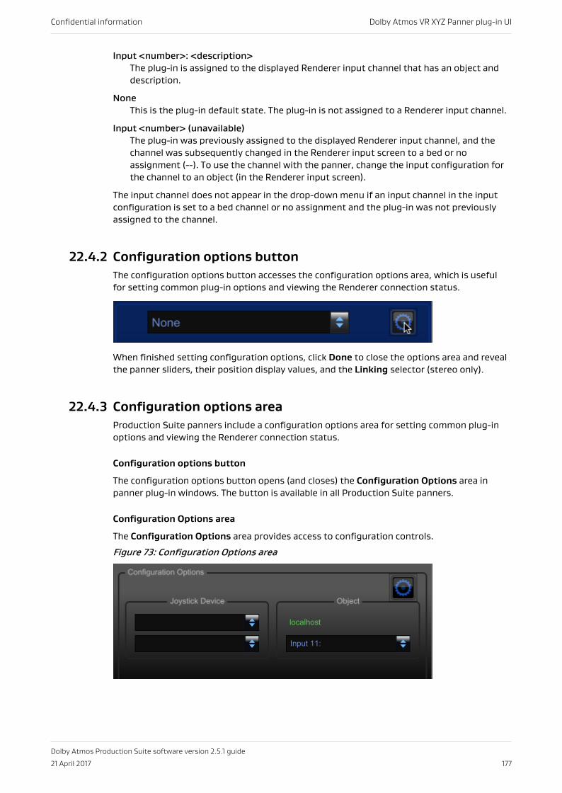
Input <number>: <description>The plug-in is assigned to the displayed Renderer input channel that has an object anddescription.
NoneThis is the plug-in default state. The plug-in is not assigned to a Renderer input channel.
Input <number> (unavailable)The plug-in was previously assigned to the displayed Renderer input channel, and thechannel was subsequently changed in the Renderer input screen to a bed or noassignment (--). To use the channel with the panner, change the input configuration forthe channel to an object (in the Renderer input screen).
The input channel does not appear in the drop-down menu if an input channel in the inputconfiguration is set to a bed channel or no assignment and the plug-in was not previouslyassigned to the channel.
22.4.2 Configuration options buttonThe configuration options button accesses the configuration options area, which is usefulfor setting common plug-in options and viewing the Renderer connection status.
When finished setting configuration options, click Done to close the options area and revealthe panner sliders, their position display values, and the Linking selector (stereo only).
22.4.3 Configuration options areaProduction Suite panners include a configuration options area for setting common plug-inoptions and viewing the Renderer connection status.
Configuration options button
The configuration options button opens (and closes) the Configuration Options area inpanner plug-in windows. The button is available in all Production Suite panners.
Configuration Options area
The Configuration Options area provides access to configuration controls.
Figure 73: Configuration Options area
Confidential information Dolby Atmos VR XYZ Panner plug-in UI
Dolby Atmos Production Suite software version 2.5.1 guide
21 April 2017 177
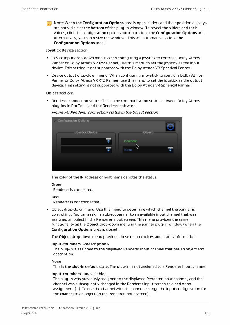
Note: When the Configuration Options area is open, sliders and their position displaysare not visible at the bottom of the plug-in window. To reveal the sliders and theirvalues, click the configuration options button to close the Configuration Options area.Alternatively, you can resize the window. (This will automatically close theConfiguration Options area.)
Joystick Device section:
• Device input drop-down menu: When configuring a joystick to control a Dolby AtmosPanner or Dolby Atmos VR XYZ Panner, use this menu to set the joystick as the inputdevice. This setting is not supported with the Dolby Atmos VR Spherical Panner.
• Device output drop-down menu: When configuring a joystick to control a Dolby AtmosPanner or Dolby Atmos VR XYZ Panner, use this menu to set the joystick as the outputdevice. This setting is not supported with the Dolby Atmos VR Spherical Panner.
Object section:
• Renderer connection status: This is the communication status between Dolby Atmosplug-ins in Pro Tools and the Renderer software.
Figure 74: Renderer connection status in the Object section
The color of the IP address or host name denotes the status:
GreenRenderer is connected.
RedRenderer is not connected.
• Object drop-down menu: Use this menu to determine which channel the panner iscontrolling. You can assign an object panner to an available input channel that wasassigned an object in the Renderer input screen. This menu provides the samefunctionality as the Object drop-down menu in the panner plug-in window (when theConfiguration Options area is closed).
The Object drop-down menu provides these menu choices and status information:
Input <number>: <description>The plug-in is assigned to the displayed Renderer input channel that has an object anddescription.
NoneThis is the plug-in default state. The plug-in is not assigned to a Renderer input channel.
Input <number> (unavailable)The plug-in was previously assigned to the displayed Renderer input channel, and thechannel was subsequently changed in the Renderer input screen to a bed or noassignment (--). To use the channel with the panner, change the input configuration forthe channel to an object (in the Renderer input screen).
Confidential information Dolby Atmos VR XYZ Panner plug-in UI
Dolby Atmos Production Suite software version 2.5.1 guide
21 April 2017 178
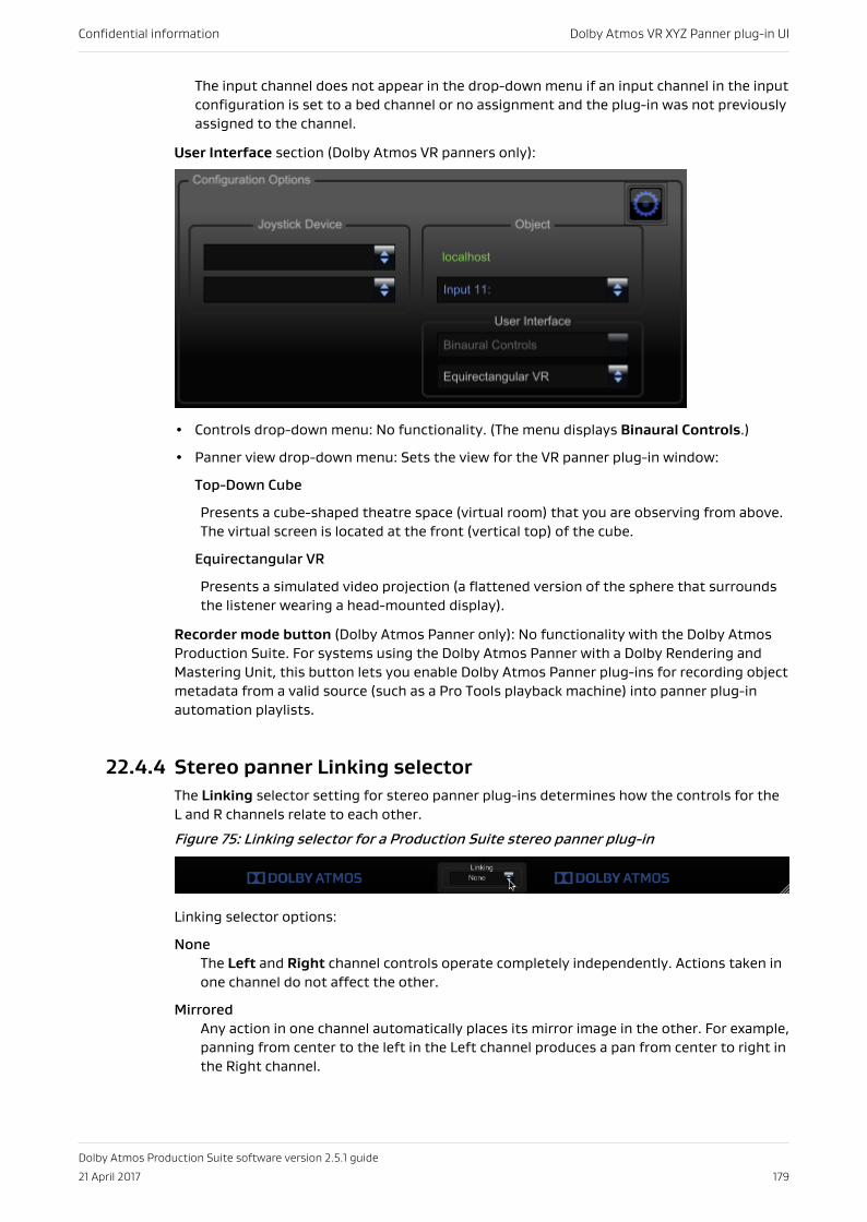
The input channel does not appear in the drop-down menu if an input channel in the inputconfiguration is set to a bed channel or no assignment and the plug-in was not previouslyassigned to the channel.
User Interface section (Dolby Atmos VR panners only):
• Controls drop-down menu: No functionality. (The menu displays Binaural Controls.)
• Panner view drop-down menu: Sets the view for the VR panner plug-in window:
Top-Down Cube
Presents a cube-shaped theatre space (virtual room) that you are observing from above.The virtual screen is located at the front (vertical top) of the cube.
Equirectangular VR
Presents a simulated video projection (a flattened version of the sphere that surroundsthe listener wearing a head-mounted display).
Recorder mode button (Dolby Atmos Panner only): No functionality with the Dolby AtmosProduction Suite. For systems using the Dolby Atmos Panner with a Dolby Rendering andMastering Unit, this button lets you enable Dolby Atmos Panner plug-ins for recording objectmetadata from a valid source (such as a Pro Tools playback machine) into panner plug-inautomation playlists.
22.4.4 Stereo panner Linking selectorThe Linking selector setting for stereo panner plug-ins determines how the controls for theL and R channels relate to each other.
Figure 75: Linking selector for a Production Suite stereo panner plug-in
Linking selector options:
NoneThe Left and Right channel controls operate completely independently. Actions taken inone channel do not affect the other.
MirroredAny action in one channel automatically places its mirror image in the other. For example,panning from center to the left in the Left channel produces a pan from center to right inthe Right channel.
Confidential information Dolby Atmos VR XYZ Panner plug-in UI
Dolby Atmos Production Suite software version 2.5.1 guide
21 April 2017 179
CopyAny action in one channel is copied to the other. For example, panning from the center tothe left in the Left channel also produces a pan from center to left in the Right channel.
22.4.5 Resize window controlAll Production Suite panner plug-ins provide a control for resizing the plug-in window. Thecontrol is located at the lower-right corner of the plug-in window and is shaded.
After you resize a panner plug-in window, the new size is applied to subsequently openedpanner plug-ins until you do a new resize.
Confidential information Dolby Atmos VR XYZ Panner plug-in UI
Dolby Atmos Production Suite software version 2.5.1 guide
21 April 2017 180
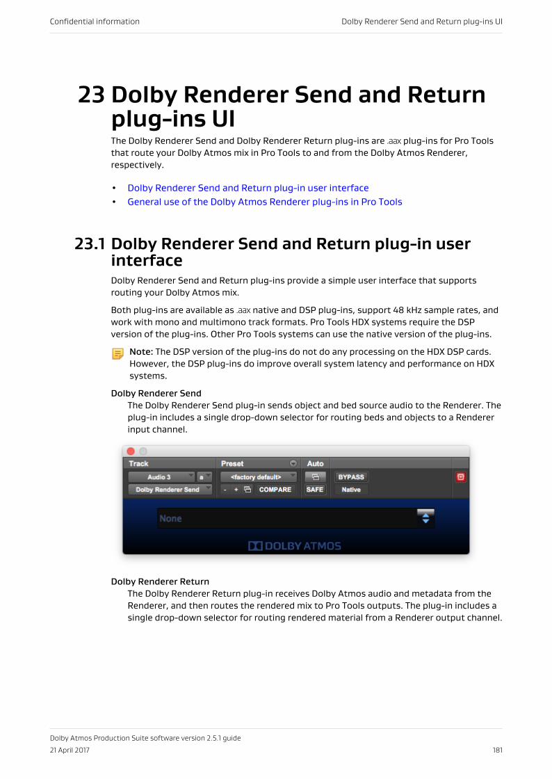
23 Dolby Renderer Send and Returnplug-ins UIThe Dolby Renderer Send and Dolby Renderer Return plug-ins are .aax plug-ins for Pro Toolsthat route your Dolby Atmos mix in Pro Tools to and from the Dolby Atmos Renderer,respectively.
• Dolby Renderer Send and Return plug-in user interface• General use of the Dolby Atmos Renderer plug-ins in Pro Tools
23.1 Dolby Renderer Send and Return plug-in userinterfaceDolby Renderer Send and Return plug-ins provide a simple user interface that supportsrouting your Dolby Atmos mix.
Both plug-ins are available as .aax native and DSP plug-ins, support 48 kHz sample rates, andwork with mono and multimono track formats. Pro Tools HDX systems require the DSPversion of the plug-ins. Other Pro Tools systems can use the native version of the plug-ins.
Note: The DSP version of the plug-ins do not do any processing on the HDX DSP cards.However, the DSP plug-ins do improve overall system latency and performance on HDXsystems.
Dolby Renderer SendThe Dolby Renderer Send plug-in sends object and bed source audio to the Renderer. Theplug-in includes a single drop-down selector for routing beds and objects to a Rendererinput channel.
Dolby Renderer ReturnThe Dolby Renderer Return plug-in receives Dolby Atmos audio and metadata from theRenderer, and then routes the rendered mix to Pro Tools outputs. The plug-in includes asingle drop-down selector for routing rendered material from a Renderer output channel.
Confidential information Dolby Renderer Send and Return plug-ins UI
Dolby Atmos Production Suite software version 2.5.1 guide
21 April 2017 181
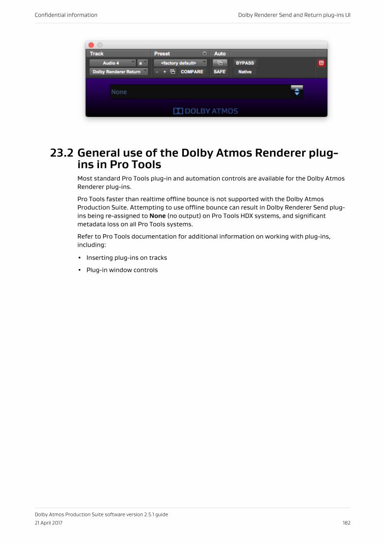
23.2 General use of the Dolby Atmos Renderer plug-ins in Pro ToolsMost standard Pro Tools plug-in and automation controls are available for the Dolby AtmosRenderer plug-ins.
Pro Tools faster than realtime offline bounce is not supported with the Dolby AtmosProduction Suite. Attempting to use offline bounce can result in Dolby Renderer Send plug-ins being re-assigned to None (no output) on Pro Tools HDX systems, and significantmetadata loss on all Pro Tools systems.
Refer to Pro Tools documentation for additional information on working with plug-ins,including:
• Inserting plug-ins on tracks
• Plug-in window controls
Confidential information Dolby Renderer Send and Return plug-ins UI
Dolby Atmos Production Suite software version 2.5.1 guide
21 April 2017 182
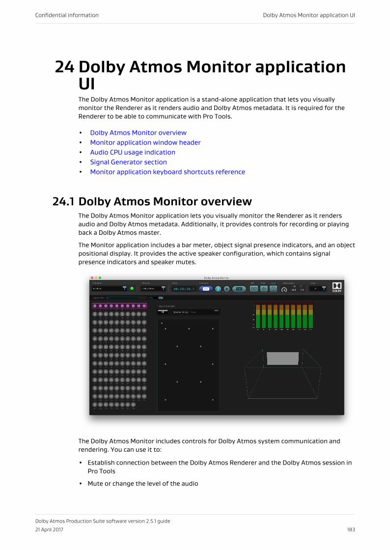
24 Dolby Atmos Monitor applicationUIThe Dolby Atmos Monitor application is a stand-alone application that lets you visuallymonitor the Renderer as it renders audio and Dolby Atmos metadata. It is required for theRenderer to be able to communicate with Pro Tools.
• Dolby Atmos Monitor overview• Monitor application window header• Audio CPU usage indication• Signal Generator section• Monitor application keyboard shortcuts reference
24.1 Dolby Atmos Monitor overviewThe Dolby Atmos Monitor application lets you visually monitor the Renderer as it rendersaudio and Dolby Atmos metadata. Additionally, it provides controls for recording or playingback a Dolby Atmos master.
The Monitor application includes a bar meter, object signal presence indicators, and an objectpositional display. It provides the active speaker configuration, which contains signalpresence indicators and speaker mutes.
The Dolby Atmos Monitor includes controls for Dolby Atmos system communication andrendering. You can use it to:
• Establish connection between the Dolby Atmos Renderer and the Dolby Atmos session inPro Tools
• Mute or change the level of the audio
Confidential information Dolby Atmos Monitor application UI
Dolby Atmos Production Suite software version 2.5.1 guide
21 April 2017 183
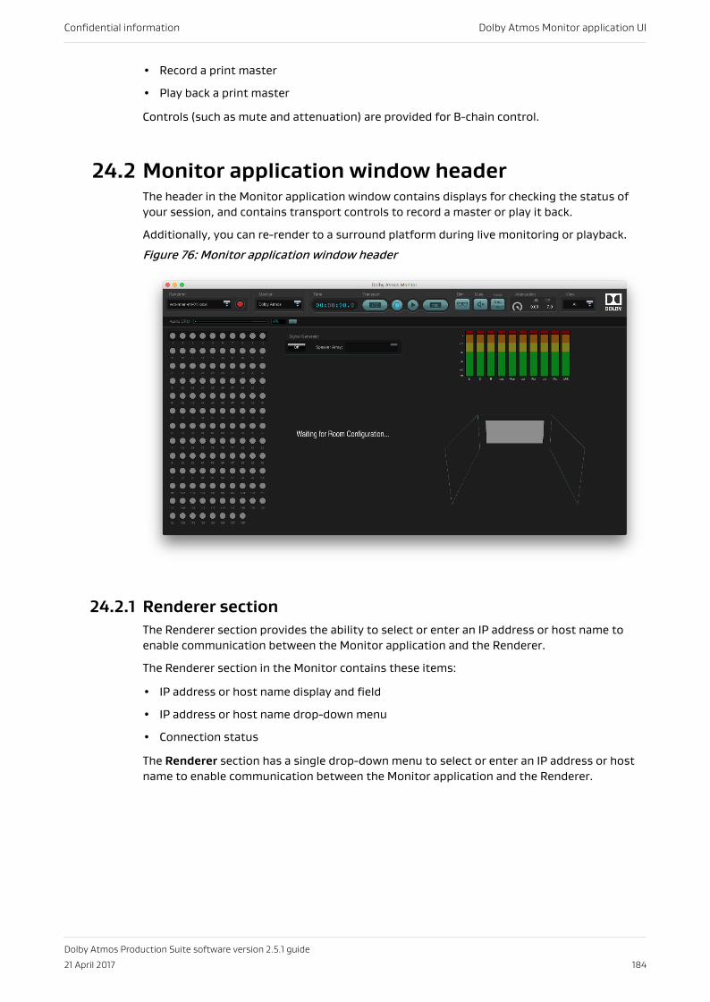
• Record a print master
• Play back a print master
Controls (such as mute and attenuation) are provided for B-chain control.
24.2 Monitor application window headerThe header in the Monitor application window contains displays for checking the status ofyour session, and contains transport controls to record a master or play it back.
Additionally, you can re-render to a surround platform during live monitoring or playback.
Figure 76: Monitor application window header
24.2.1 Renderer sectionThe Renderer section provides the ability to select or enter an IP address or host name toenable communication between the Monitor application and the Renderer.
The Renderer section in the Monitor contains these items:
• IP address or host name display and field
• IP address or host name drop-down menu
• Connection status
The Renderer section has a single drop-down menu to select or enter an IP address or hostname to enable communication between the Monitor application and the Renderer.
Confidential information Dolby Atmos Monitor application UI
Dolby Atmos Production Suite software version 2.5.1 guide
21 April 2017 184
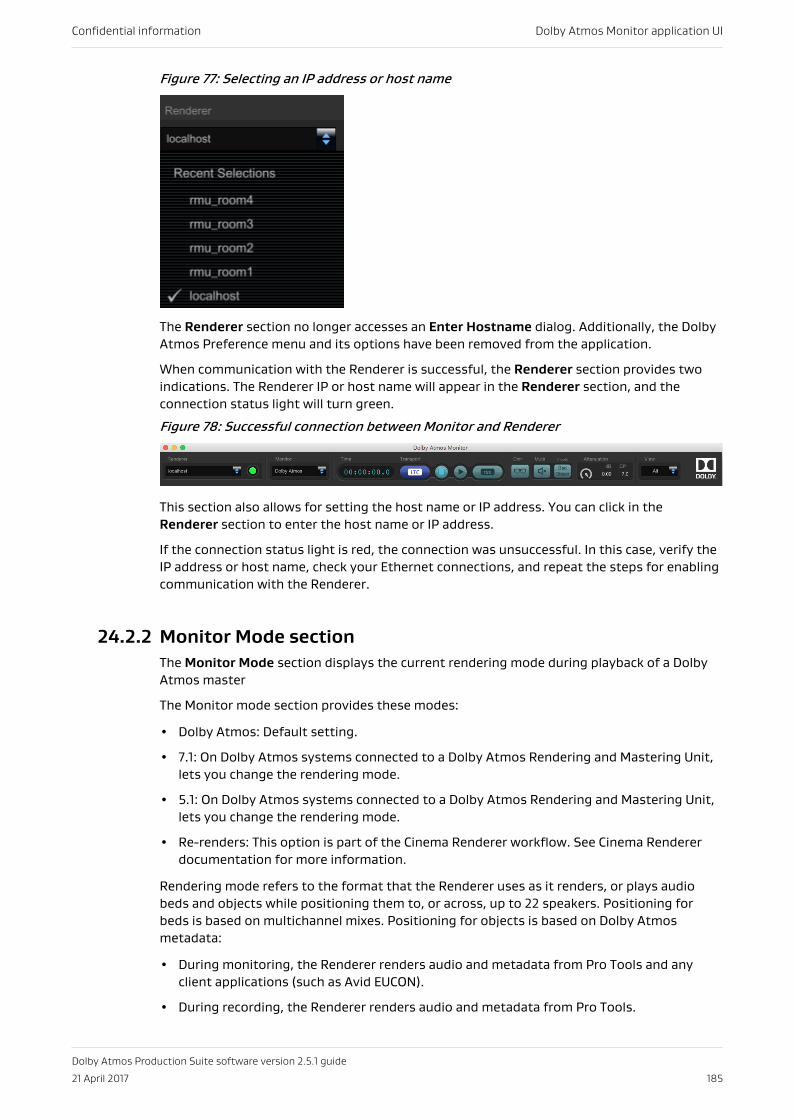
Figure 77: Selecting an IP address or host name
The Renderer section no longer accesses an Enter Hostname dialog. Additionally, the DolbyAtmos Preference menu and its options have been removed from the application.
When communication with the Renderer is successful, the Renderer section provides twoindications. The Renderer IP or host name will appear in the Renderer section, and theconnection status light will turn green.
Figure 78: Successful connection between Monitor and Renderer
This section also allows for setting the host name or IP address. You can click in theRenderer section to enter the host name or IP address.
If the connection status light is red, the connection was unsuccessful. In this case, verify theIP address or host name, check your Ethernet connections, and repeat the steps for enablingcommunication with the Renderer.
24.2.2 Monitor Mode sectionThe Monitor Mode section displays the current rendering mode during playback of a DolbyAtmos master
The Monitor mode section provides these modes:
• Dolby Atmos: Default setting.
• 7.1: On Dolby Atmos systems connected to a Dolby Atmos Rendering and Mastering Unit,lets you change the rendering mode.
• 5.1: On Dolby Atmos systems connected to a Dolby Atmos Rendering and Mastering Unit,lets you change the rendering mode.
• Re-renders: This option is part of the Cinema Renderer workflow. See Cinema Rendererdocumentation for more information.
Rendering mode refers to the format that the Renderer uses as it renders, or plays audiobeds and objects while positioning them to, or across, up to 22 speakers. Positioning forbeds is based on multichannel mixes. Positioning for objects is based on Dolby Atmosmetadata:
• During monitoring, the Renderer renders audio and metadata from Pro Tools and anyclient applications (such as Avid EUCON).
• During recording, the Renderer renders audio and metadata from Pro Tools.
Confidential information Dolby Atmos Monitor application UI
Dolby Atmos Production Suite software version 2.5.1 guide
21 April 2017 185
• During playback, the Renderer renders material from the recorded master (located on themachine running the Renderer).
Note: The setting of the rendering mode in the Monitor does not affect the recording.The rendering mode affects only what is being listened to during recording. A mastercreated with the Monitor is always a Dolby Atmos master.
24.2.3 Time sectionThe Time section displays the running time of the Renderer during live monitoring, recordinga master, or playing back a master. The time scale is in hours:minutes:seconds:frames persecond.
24.2.4 Transport sectionThe Monitor application provides transport buttons in the Transport section. All of thesebuttons, except for the record arm, slave to the Pro Tools transport and cannot be changed.
• Chase linear timecode (LTC): This button is on for all Renderer workflows, and cannot bedisabled.
• Stop.
• Play.
• Record arm.
24.2.5 Dim sectionUse the Dim button to lower the volume of signal at the Dolby Atmos Renderer speakeroutput. The Dim button provides –20 dB of attenuation, pre-metering.
Dim buttonThe Dim button displays as glasses (shades).
24.2.6 Mute sectionThe mute section provides the ability to mute Renderer output for speaker playback, pre-metering.
Mute buttonThe mute button displays as a speaker icon. The icon has the same look and functionalityas the one in the Renderer. The Mute button lets you mute (or unmute) Renderer outputfor speaker playback only.
Bed and Object buttonsYou can use these buttons to mute input from beds only, objects only, or both.
24.2.7 Attenuation sectionThe Attenuation section provides multiple ways for changing the gain of Renderer output.
Output attenuation controlProvides gain control of Renderer output via a mouse. The attenuation range is 0.00 dBto –Inf and is reflected in the dB field (and in the CP field, in cinema processor units).When set to –Inf (–∞), audio is effectively muted.
Confidential information Dolby Atmos Monitor application UI
Dolby Atmos Production Suite software version 2.5.1 guide
21 April 2017 186
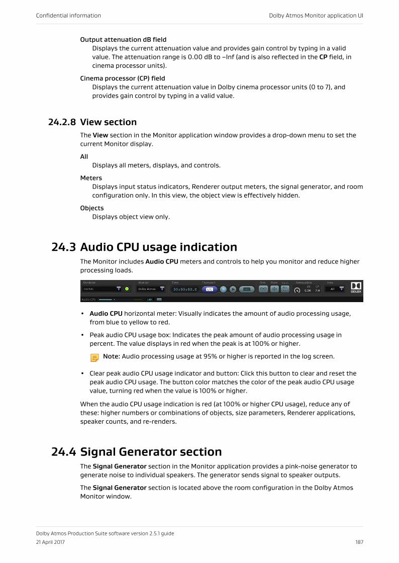
Output attenuation dB fieldDisplays the current attenuation value and provides gain control by typing in a validvalue. The attenuation range is 0.00 dB to –Inf (and is also reflected in the CP field, incinema processor units).
Cinema processor (CP) fieldDisplays the current attenuation value in Dolby cinema processor units (0 to 7), andprovides gain control by typing in a valid value.
24.2.8 View sectionThe View section in the Monitor application window provides a drop-down menu to set thecurrent Monitor display.
AllDisplays all meters, displays, and controls.
MetersDisplays input status indicators, Renderer output meters, the signal generator, and roomconfiguration only. In this view, the object view is effectively hidden.
ObjectsDisplays object view only.
24.3 Audio CPU usage indicationThe Monitor includes Audio CPU meters and controls to help you monitor and reduce higherprocessing loads.
• Audio CPU horizontal meter: Visually indicates the amount of audio processing usage,from blue to yellow to red.
• Peak audio CPU usage box: Indicates the peak amount of audio processing usage inpercent. The value displays in red when the peak is at 100% or higher.
Note: Audio processing usage at 95% or higher is reported in the log screen.
• Clear peak audio CPU usage indicator and button: Click this button to clear and reset thepeak audio CPU usage. The button color matches the color of the peak audio CPU usagevalue, turning red when the value is 100% or higher.
When the audio CPU usage indication is red (at 100% or higher CPU usage), reduce any ofthese: higher numbers or combinations of objects, size parameters, Renderer applications,speaker counts, and re-renders.
24.4 Signal Generator sectionThe Signal Generator section in the Monitor application provides a pink-noise generator togenerate noise to individual speakers. The generator sends signal to speaker outputs.
The Signal Generator section is located above the room configuration in the Dolby AtmosMonitor window.
Confidential information Dolby Atmos Monitor application UI
Dolby Atmos Production Suite software version 2.5.1 guide
21 April 2017 187
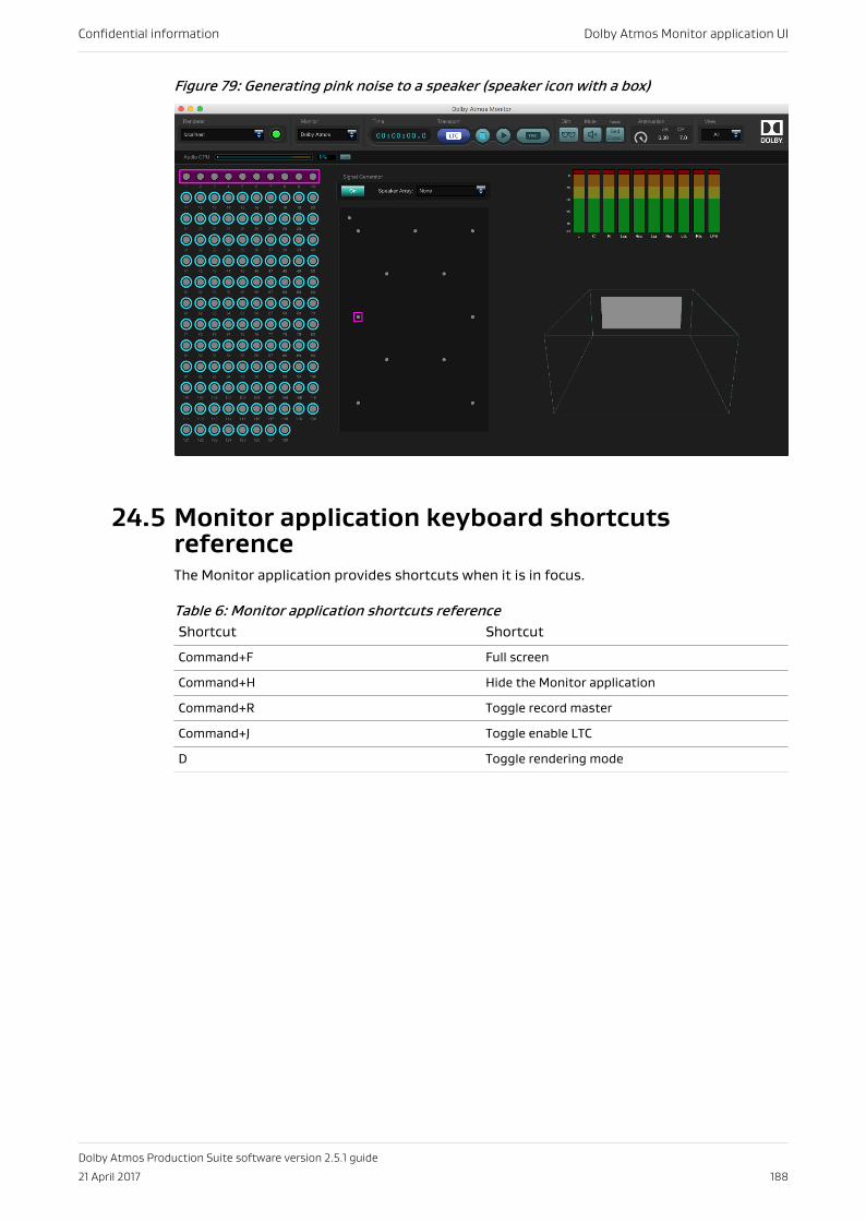
Figure 79: Generating pink noise to a speaker (speaker icon with a box)
24.5 Monitor application keyboard shortcutsreferenceThe Monitor application provides shortcuts when it is in focus.
Table 6: Monitor application shortcuts referenceShortcut Shortcut
Command+F Full screen
Command+H Hide the Monitor application
Command+R Toggle record master
Command+J Toggle enable LTC
D Toggle rendering mode
Confidential information Dolby Atmos Monitor application UI
Dolby Atmos Production Suite software version 2.5.1 guide
21 April 2017 188
25 Technology overviewsVarious Dolby technologies are an integral part of the Dolby Atmos Production Suite:Dolby Atmos master file sets, Dolby Atmos media files, and spatial coding.
• Dolby Atmos master file set• Dolby Atmos media files• Spatial coding
25.1 Dolby Atmos master file setThe Dolby Atmos Renderer stores rendered content as a Dolby Atmos master file set.
The Dolby Atmos master consists of:
• One interleaved PCM file in Core Audio format, with its name structured as<filename>.atmos.audio. This file contains the audio for all bed signals and objects.
• One metadata file, with its name structured as <filename>.atmos.metadata. This filecontains all of the 3D positional coordinates for static and dynamic signals in the .audiofile.
• One top-level file, with its name structured as <filename>.atmos. This file provides essentialinformation about the presentation contained in the master file set.
Caution: Never modify any of the Dolby Atmos content files (including the dub_out.rpl fileor <filename>.atmos).
25.2 Dolby Atmos media filesDolby Atmos media files include rendered master file sets created in a home theater or VRworkflow, cinema print masters, and other related Dolby Atmos files. You can play back (ormonitor playback of) most Dolby Atmos media files.
The Renderer supports playback of these Dolby Atmos media file formats:
• .atmos: Home theater or VR master file set.
• .damf: Older (original) home theater master file set.
• .wav (ADM BWF): This includes support of ADM BWF files converted from another DolbyAtmos media file via the Dolby Atmos Conversion Tool.
• .rpl: Cinema print master and supporting files.
• pmstitch .xml: Multiple Dolby Atmos media files stitched together via the Dolby Atmospmstitch tool. These files can include .atmos, .rpl, .wav (ADM BWF), and .mxf files.
• .mxf: Encoded cinema print master.
25.3 Spatial codingDolby Atmos spatial coding is one of the primary processing components for creating DolbyAtmos audio.
Confidential information Technology overviews
Dolby Atmos Production Suite software version 2.5.1 guide
21 April 2017 189
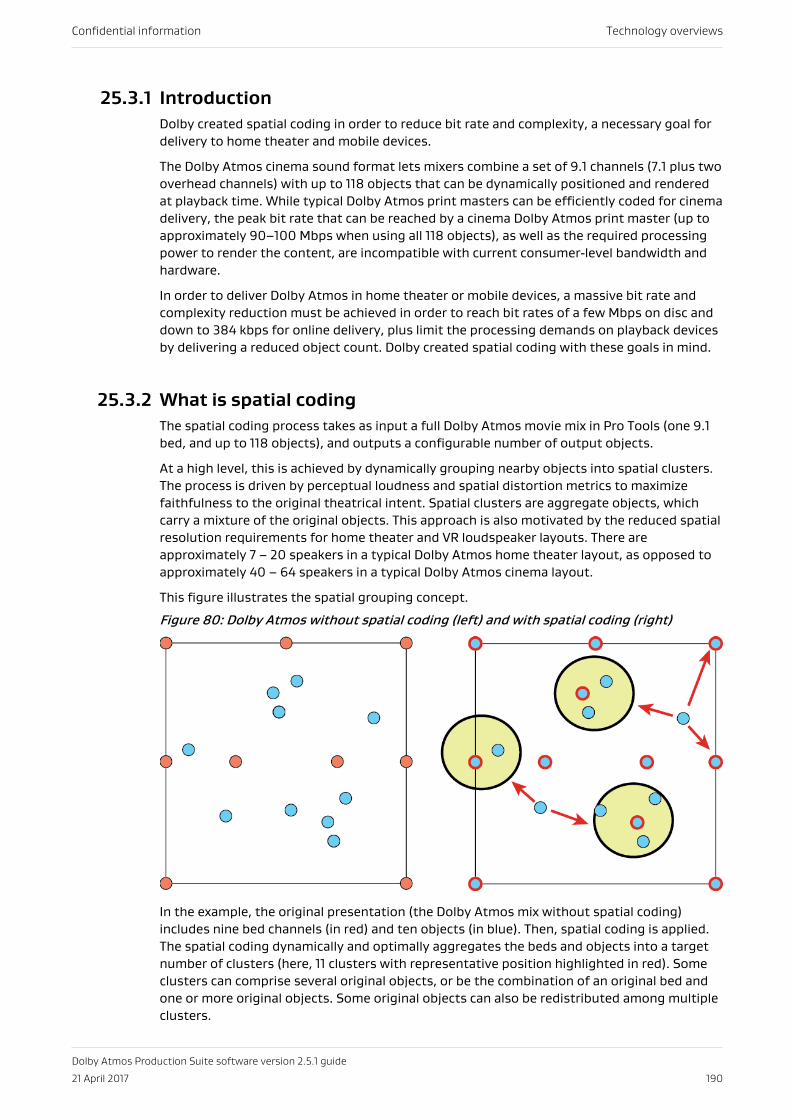
25.3.1 IntroductionDolby created spatial coding in order to reduce bit rate and complexity, a necessary goal fordelivery to home theater and mobile devices.
The Dolby Atmos cinema sound format lets mixers combine a set of 9.1 channels (7.1 plus twooverhead channels) with up to 118 objects that can be dynamically positioned and renderedat playback time. While typical Dolby Atmos print masters can be efficiently coded for cinemadelivery, the peak bit rate that can be reached by a cinema Dolby Atmos print master (up toapproximately 90–100 Mbps when using all 118 objects), as well as the required processingpower to render the content, are incompatible with current consumer‐level bandwidth andhardware.
In order to deliver Dolby Atmos in home theater or mobile devices, a massive bit rate andcomplexity reduction must be achieved in order to reach bit rates of a few Mbps on disc anddown to 384 kbps for online delivery, plus limit the processing demands on playback devicesby delivering a reduced object count. Dolby created spatial coding with these goals in mind.
25.3.2 What is spatial codingThe spatial coding process takes as input a full Dolby Atmos movie mix in Pro Tools (one 9.1bed, and up to 118 objects), and outputs a configurable number of output objects.
At a high level, this is achieved by dynamically grouping nearby objects into spatial clusters.The process is driven by perceptual loudness and spatial distortion metrics to maximizefaithfulness to the original theatrical intent. Spatial clusters are aggregate objects, whichcarry a mixture of the original objects. This approach is also motivated by the reduced spatialresolution requirements for home theater and VR loudspeaker layouts. There areapproximately 7 – 20 speakers in a typical Dolby Atmos home theater layout, as opposed toapproximately 40 – 64 speakers in a typical Dolby Atmos cinema layout.
This figure illustrates the spatial grouping concept.
Figure 80: Dolby Atmos without spatial coding (left) and with spatial coding (right)
In the example, the original presentation (the Dolby Atmos mix without spatial coding)includes nine bed channels (in red) and ten objects (in blue). Then, spatial coding is applied.The spatial coding dynamically and optimally aggregates the beds and objects into a targetnumber of clusters (here, 11 clusters with representative position highlighted in red). Someclusters can comprise several original objects, or be the combination of an original bed andone or more original objects. Some original objects can also be redistributed among multipleclusters.
Confidential information Technology overviews
Dolby Atmos Production Suite software version 2.5.1 guide
21 April 2017 190
As a result of the clustering process, spatial coding never discards any of the original objects.Instead, it compresses the original spatial information of the original Dolby Atmos mix tocreate a set of signals that can be encoded with existing core audio codecs for consumerdelivery. The mixing is a pure linear wide-band combination that preserves the energy of allof the original inputs, without any form of waveform. The end result can therefore bedelivered in a lossless way, similar to a 5.1-channel mix that is generated from an original ProTools mix session.
25.3.3 Spatial coding in the authoring chainSpatial coding is present at two distinct stages in the Dolby Atmos authoring chain: duringmonitoring of the mix, and when encoding the Dolby Atmos master file set.
At the first stage (monitoring and mastering), spatial coding occurs as a real-time emulationprocess running on the Dolby Atmos Renderer during monitoring of the mix. Here, the mixercan listen to the effect of spatial coding while making adjustments to the mix for near-fieldpresentation. The Dolby Atmos Renderer software generates a Dolby Atmos master file set(including the top-level .atmos file), which still carries the full set of up to 128 signals, andtherefore contains the mixing decisions for home theater or VR, but has not yet beenprocessed by spatial coding.
At the second stage (encoding), spatial coding is finally applied to the original beds andobjects as part of the encoding process by a software tool (such as Dolby Media Encoder).This tool reads the .atmos (or .damf) file, applies spatial coding to create the same clusteredobjects heard during the first stage of Dolby Atmos authoring, and then encodes theclustered objects into the delivery codec format (in the Dolby Media Encoder, the deliverycodec format is specified in the job setup). The Encoder generates a coded bitstream thatconsists of objects and one or more bed channels. The encoded bitstream can then bedelivered to consumer playback devices.
Supported delivery codecs include:
• Dolby TrueHD: In this case, the spatially coded objects are losslessly delivered toconsumer playback devices. Typically, the Dolby TrueHD encoder creates a bitstreamcontaining the spatially coded objects, a 7.1-ch render of the objects, and 5.1-ch and 2-chdownmixes. The 7.1, 5.1 and 2-ch presentations are backward-compatible with legacyDolby TrueHD decoders. A Dolby Atmos-capable Dolby TrueHD decoder losslessly reversesthe downmixes and render to recreate the original spatially coded objects. Dolby TrueHDalso supports independent 7.1, 5.1, and 2-channel presentations of 7.1.
• Dolby Digital Plus: In this case, the spatially coded objects are rendered to a backwardscompatible 5.1 or 7.1 core mix and side metadata is generated to extract the individualobjects from the mix. The core mix is encoded with Dolby Digital Plus in a backward-compatible manner and can be played back directly by older Dolby Digital Plus decoders.This is a lossy process due to the downmixing process, as well as the subsequent lossycoding of the base mix.
For both Dolby True HD and Dolby Digital Plus bitstreams with a 7.1-ch core, the legacy 5.1and stereo playback will be derived from the legacy layer of the mix. The 5.1 legacy layer isgenerated during encoding as a downmix from the 7.1 rendering of the spatially codedsignals, using Dolby Pro Logic IIx or Lo/Ro downmix rules. For Dolby Digital Plus bitstreamswith a 5.1-ch core, the 5.1-ch audio is generated during encoding by rendering the spatially-coded signals to 5.1 channels. Stereo downmixing is performed based on downmixing of the5.1 layer, according to standard two-channel downmixing equations.
Confidential information Technology overviews
Dolby Atmos Production Suite software version 2.5.1 guide
21 April 2017 191
25.3.4 Spatial coding configurationA limited number of spatial coding configurations are available based on the desired numberof output clusters..
In order to maximize efficiency, spatial coding converts bed channels to equivalent objects atpredefined canonical locations. Because of this, the best results are generally obtained byconfiguring spatial coding with 11 to 15 output objects and one bed channel for the LFE. (Thisbudget of audio signals is referred to as the number of elements in both the Dolby AtmosRenderer and the Dolby Media Encoder software application. Both Dolby Atmos Renderersoftware and Dolby bitstream codecs support choices of 12, 14, or 16 elements.)
25.3.5 Spatial coding limitations and fine tuningThe spatial coding technology is powerful, but due to constraints of the target media andplayback environment, it has limitations and effects that should be considered duringauthoring.
• Metadata prebaking/override: In order to group more objects in a more efficient way,spatial coding can override or prebake the result of some of the Dolby Atmos zone masksand snap metadata. This can lead to differences in rendering behavior when compared toa Cinema Renderer. We recommend that the mix be monitored in different configurationsto validate the possible effect of these changes. If the resulting effect is not desirable, werecommend manually overriding or modifying the zone masks for these specific objects.One specific example is the no sides zone exclusion, which can result in objects goingdirectly to the sides. This exclusion can typically be switched off in home mixes.
• Size/decorrelation prebaking: The home theater and VR renderer implementation cannotsupport size and decorrelation processing in the same manner as the Cinema Rendererwould on most hardware targets, due to computational power constraints. Instead,spatial coding is also responsible for pre-rendering the effect of the size anddecorrelation filters into the set of spatially coded output signals fed to the encoder. Werecommend evaluating the resulting mix over a variety of speaker configurations (inparticular, legacy configurations).
• Conversion of beds to objects: As previously mentioned, spatial coding is more effectivewhen beds can be converted to objects. However, the bed and object paths are not 100%identical in the renderer. In particular, the Dolby Atmos Renderer software for hometheater and VR implements an automatic level adjustment algorithm on the objects toavoid level buildup and better preserve the screen-to-surround balance of the mix as thenumber of output speakers is reduced. This may introduce a slight change in surroundbed levels (compared to cinema bed downmix equations). For example, surround bedsand objects near the surround or overhead speakers get attenuated up to –1.5 dB in 7.1,up to –3 dB in 5.1, and up to –4.5 dB in stereo. Normally, this is aesthetically desirable, butif it is not desired, the bed configuration can be set to allow side or rear bed signals topass through without trim. However, this choice will reduce the number of availablesignals for clustering, potentially reducing spatial resolution. Consult your Dolby fieldsupport representative when considering any bed configuration option other than LFE.
When beds are converted to objects, they also receive canonical coordinates that maylead to a re-rendering that is different from the cinema bed downmixing rules. Forinstance, the side and overhead beds generally receive a Y=0.5 coordinate whenconverted to objects and would therefore be re-rendered fully to the side speakers in 7.1.If this does not produce a desirable result, it is possible to convert the beds to objectswithin the Pro Tools session and manually adjust their coordinates (for example, slightly
Confidential information Technology overviews
Dolby Atmos Production Suite software version 2.5.1 guide
21 April 2017 192
pushing them back to Y=0.6). This, of course, will affect all presentations, but should helpachieve a better global compromise.
Confidential information Technology overviews
Dolby Atmos Production Suite software version 2.5.1 guide
21 April 2017 193
GlossaryASCII
American Standard Code for Information Interchange.
B-formatA speaker-independent representation of a soundfield.
containerA formatted file (such as an MP4 file) comprising one or more multiplexed elementarystreams and including format-specific metadata. A container demultiplexer usescontainer metadata to extract the constituent elementary streams, but this metadata isgenerally not sufficient to decode these streams. A container format is a specification(such as MPEG-4) describing the architecture of a container.
CPUCentral processing unit.
dBFSDecibels full scale. The amplitude of a signal relative to a digital full-scale signal.
Dolby Digital PlusAn advanced perceptual audio-coding system that expands and improves Dolby Digitalcoding technology, with higher bandwidth efficiencies, support for additional channels,and enhanced metadata capabilities.
Dolby RMUDolby Rendering and Mastering Unit.
DSPDigital signal processor. A specialized microprocessor optimized for digital signalprocessing.
EQEqualization. The adjustment of audio frequency responses for practical or aestheticreasons.
FFOAFirst frame of action. The point on a film reel or corresponding file at which the programcontent begins.
fpsFrames per second. The number of unique consecutive images (frames) an imagingdevice produces in one second.
frameIn audio, a series of PCM samples or encoded audio data representing the same timeinterval for all channels in the configuration. Metadata pertaining to the frame can becarried within the frame or separately, depending on context.
Confidential information Glossary
Dolby Atmos Production Suite software version 2.5.1 guide
21 April 2017 194
HDMIHigh-Definition Multimedia Interface. A high-speed, high-capacity format fortransferring digital information and the specific hardware interface for the format.
HMD
A display device, worn on the head, with display optics in front of the eyes.
I/OInput/output. The communication between a system and an entity outside the system,such as another system or a human being.
IP addressInternet Protocol address. A numerical identifier assigned to a device that is a member ofa network that uses the Internet Protocol for communication.
LFELow-Frequency Effects. A band-limited channel specifically intended for deep, low-pitched sounds.
LTCLinear timecode. A timecode developed by the Society of Motion Picture and TelevisionEngineers (SMPTE) that provides a time reference for editing, synchronization, andidentification.
MADIMultichannel Audio Digital Interface. A communications protocol for an interface thatcarries multiple channels of digital audio, defined by the Audio Engineering Society. Alsoknown as AES10.
objectAn audio signal plus associated object audio metadata.
PCMPulse code modulation. A standard method used to digitally represent sampled analogsignals. PCM is the standard form of digital audio in computers, compact discs, digitaltelephones, and other digital audio applications.
playlistAn extended .m3u8 file that contains one or more uniform resource identifiers (URIs). AURI can point to another playlist or to a media file.
renderingProcessing of audio content to adapt it to specific speaker layouts, such as 5.1- and 7.1-speaker feeds, or headphones and sound bars.
UIUser interface.
USBUniversal Serial Bus. A standard that defines the cables, connectors, andcommunications protocols used in connections between computers and electronicdevices.
Confidential information Glossary
Dolby Atmos Production Suite software version 2.5.1 guide
21 April 2017 195