Embed Size (px)
Citation preview
DOIM Parallel Optical Links: TX/RX
S. Hou, R.S. Lu19-Dec-2003, Lake Geneva
Outline
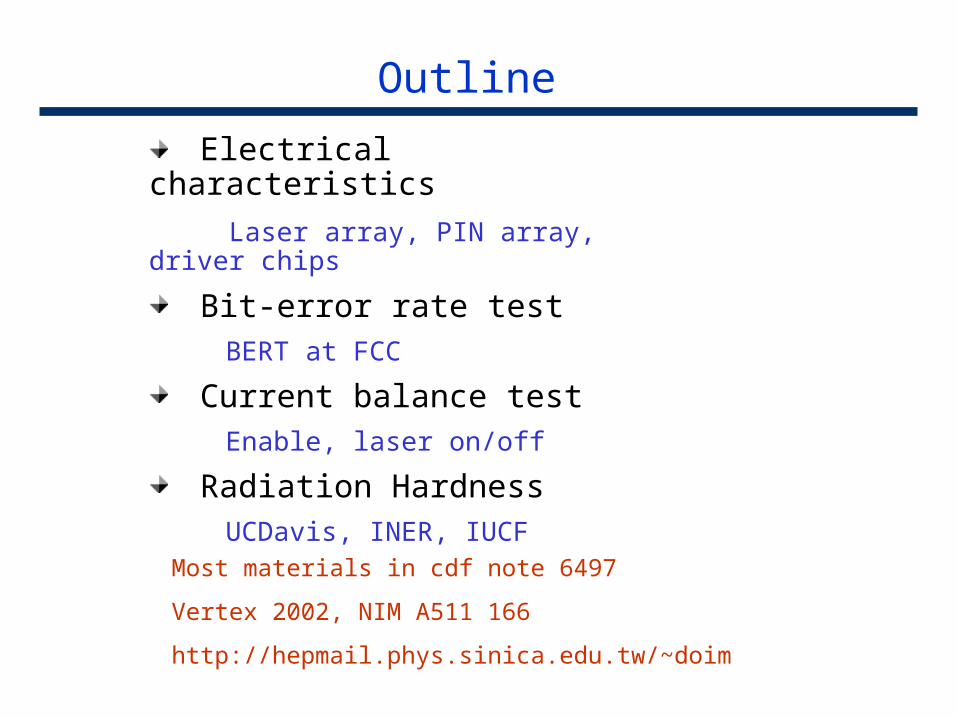
Electrical characteristics
Laser array, PIN array, driver chips
Bit-error rate test BERT at FCC
Current balance test Enable, laser on/off
Radiation Hardness UCDavis, INER, IUCF
Most materials in cdf note 6497
Vertex 2002, NIM A511 166
http://hepmail.phys.sinica.edu.tw/~doim
Introduction
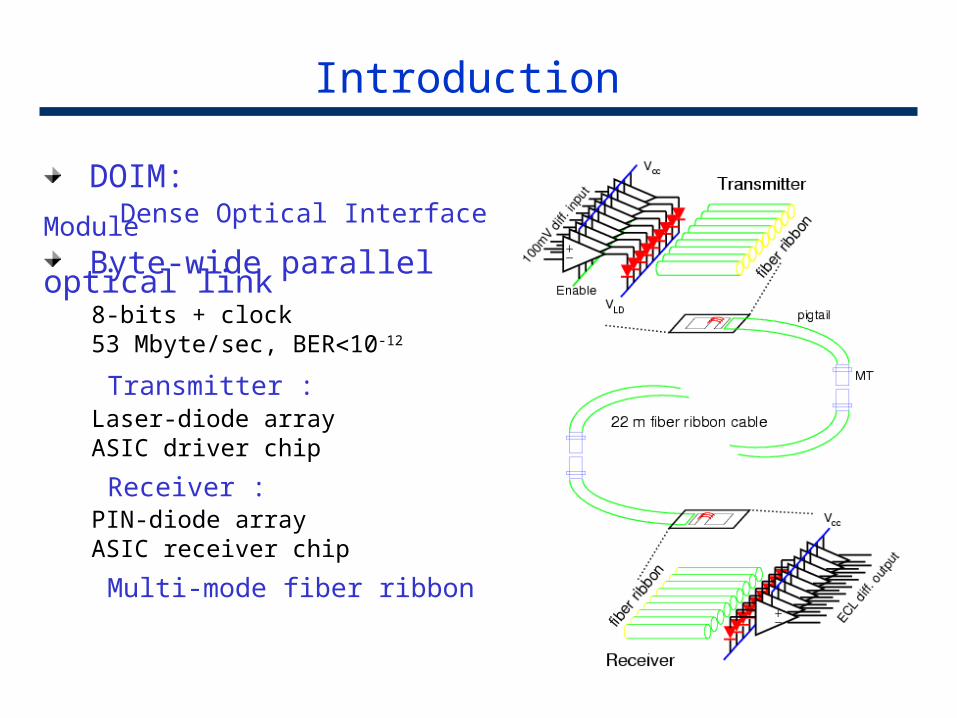
DOIM: Dense Optical Interface Module
Byte-wide parallel optical link8-bits + clock53 Mbyte/sec, BER10-12
Transmitter :Laser-diode arrayASIC driver chip
Receiver :PIN-diode arrayASIC receiver chip
Multi-mode fiber ribbon
DOIM implementation : transmitters
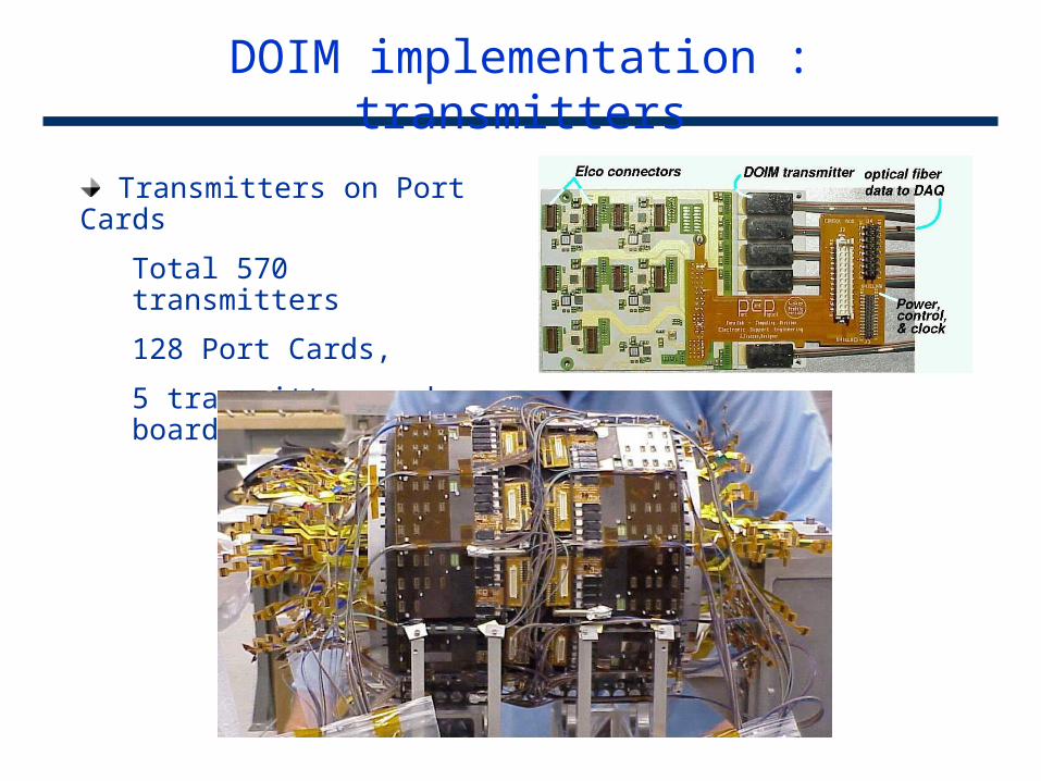
Transmitters on Port Cards
Total 570 transmitters
128 Port Cards,
5 transmitter each board
DOIM implementation : receivers
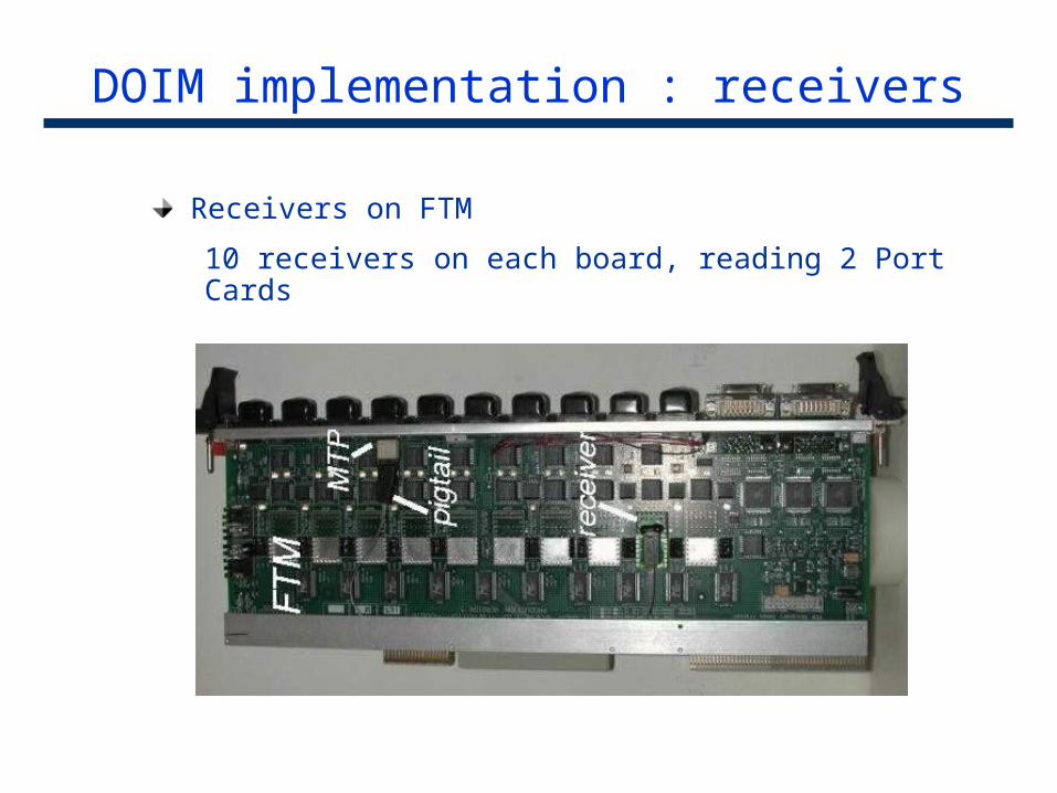
Receivers on FTM
10 receivers on each board, reading 2 Port Cards
Laser diode array
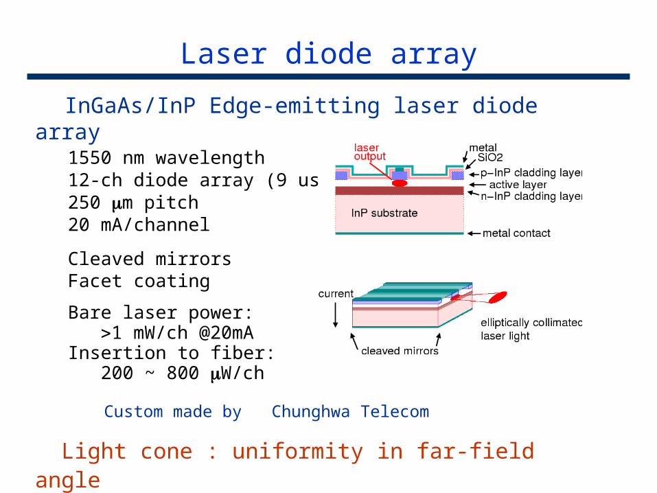
InGaAs/InP Edge-emitting laser diode array1550 nm wavelength12-ch diode array (9 used)250 m pitch20 mA/channel
Cleaved mirrorsFacet coating
Bare laser power: 1 mW/ch @20mAInsertion to fiber: 200 ~ 800 W/ch
Custom made by Chunghwa Telecom
Light cone : uniformity in far-field angle major application problem
Laser transmitter ASIC driver
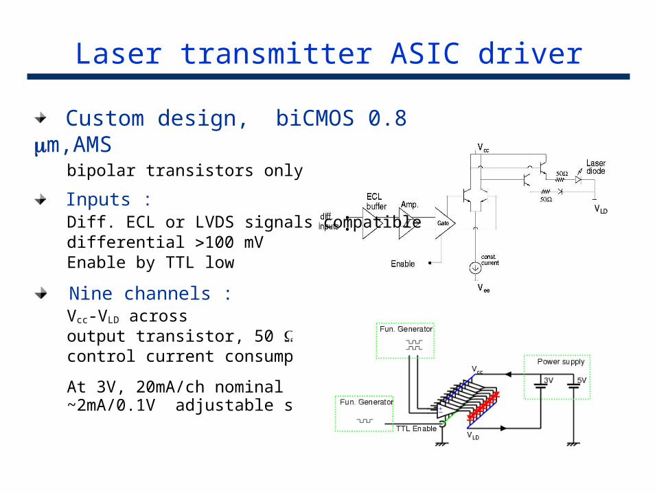
Custom design, biCMOS 0.8 m,AMSbipolar transistors only
Inputs :Diff. ECL or LVDS signals compatibledifferential 100 mVEnable by TTL low
Nine channels :Vcc-VLD across output transistor, 50 , laser control current consumption
At 3V, 20mA/ch nominal ~2mA/0.1V adjustable slope
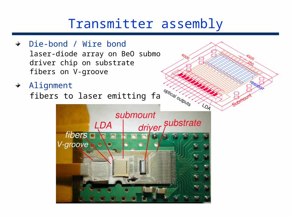
Transmitter assembly
Die-bond / Wire bondlaser-diode array on BeO submountdriver chip on substratefibers on V-groove
Alignmentfibers to laser emitting facets
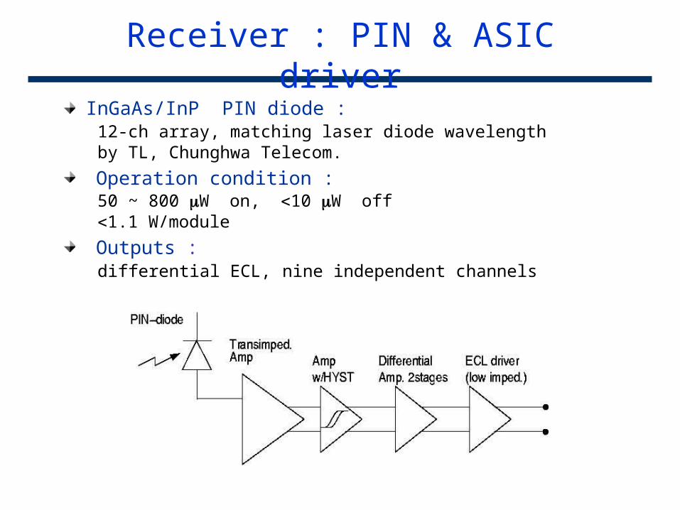
Receiver : PIN & ASIC driver
InGaAs/InP PIN diode :12-ch array, matching laser diode wavelengthby TL, Chunghwa Telecom.
Operation condition :50 ~ 800 W on, 10 W off1.1 W/module
Outputs :differential ECL, nine independent channels
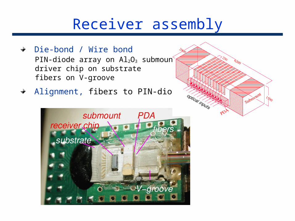
Receiver assembly
Die-bond / Wire bondPIN-diode array on Al2O3 submountdriver chip on substratefibers on V-groove
Alignment, fibers to PIN-diodes
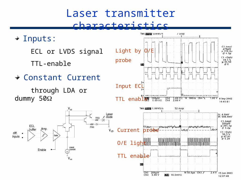
Laser transmitter characteristics
Inputs:
ECL or LVDS signal
TTL-enable
Constant Current
through LDA or dummy 50
Light by O/E probe
Input ECL
TTL enable
Current probe
O/E light
TTL enable
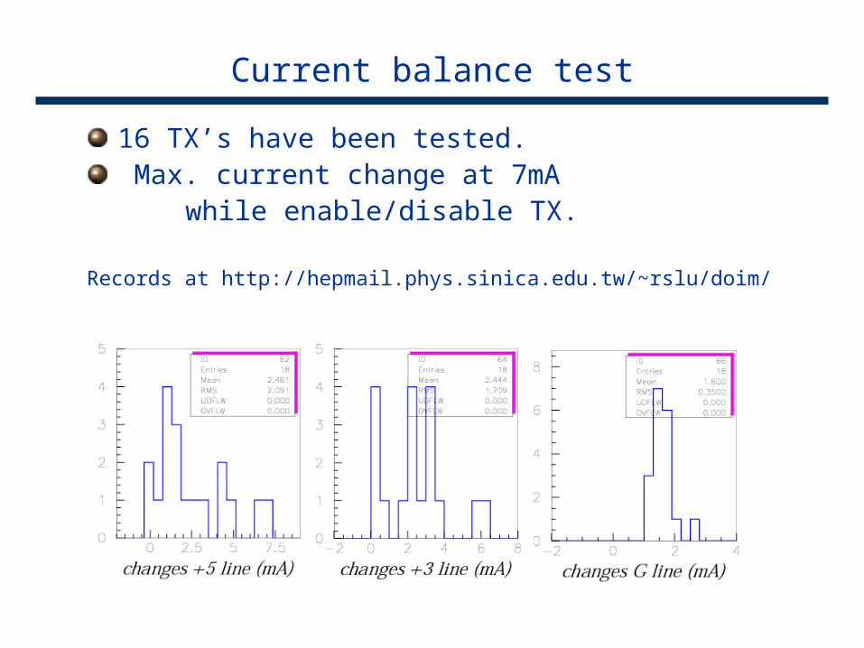
Current balance test
16 TX’s have been tested. Max. current change at 7mA
while enable/disable TX.
Records at http://hepmail.phys.sinica.edu.tw/~rslu/doim/
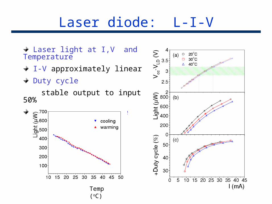
Laser diode: L-I-V
Laser light at I,V and Temperature
I-V approximately linear
Duty cycle
stable output to input 50%
Linear to temperature
Temp (oC)
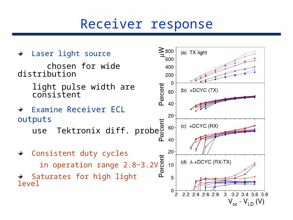
Receiver response
Laser light source
chosen for wide distribution
light pulse width are consistent
Examine Receiver ECL outputs
use Tektronix diff. probe
Consistent duty cycles
in operation range 2.8~3.2V
Saturates for high light level
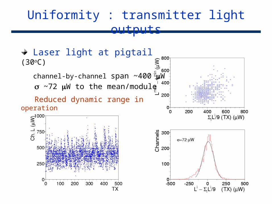
Uniformity : transmitter light outputs
Laser light at pigtail (30oC)
channel-by-channel span ~400 W
~72 W to the mean/module
Reduced dynamic range in operation
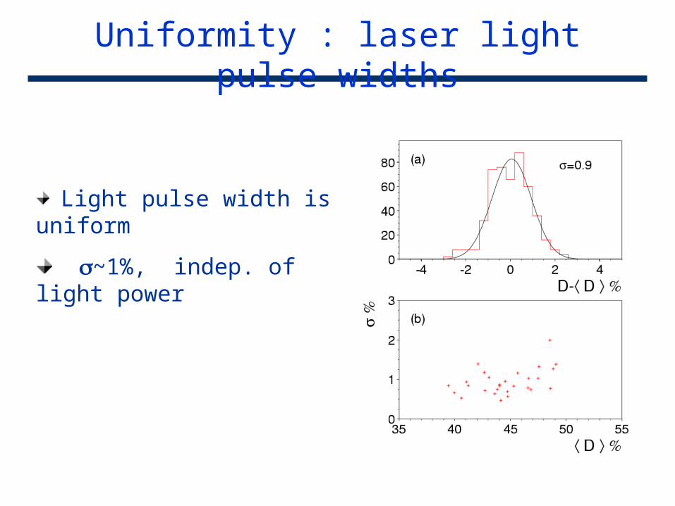
Uniformity : laser light pulse widths
Light pulse width is uniform
~1%, indep. of light power
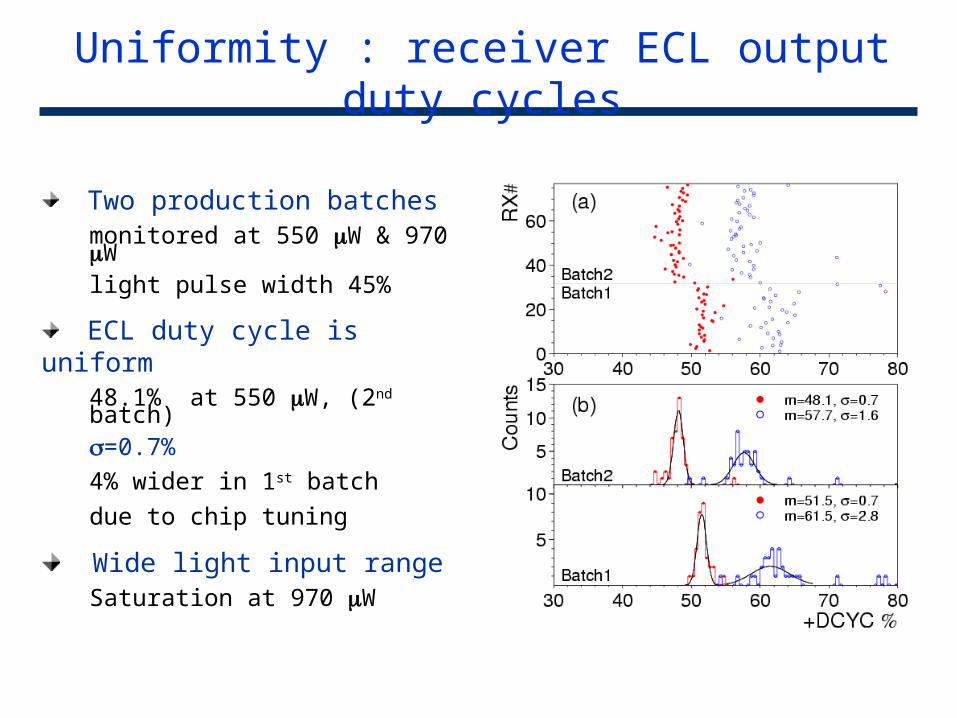
Uniformity : receiver ECL output duty cycles
Two production batchesmonitored at 550 W & 970 Wlight pulse width 45%
ECL duty cycle is uniform48.1% at 550 W, (2nd batch)=0.7%
4% wider in 1st batch
due to chip tuning
Wide light input range Saturation at 970 W
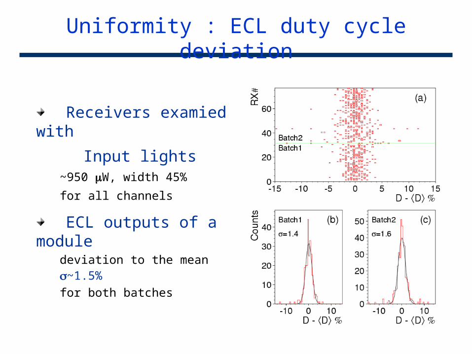
Uniformity : ECL duty cycle deviation
Receivers examied with
Input lights~950 W, width 45%
for all channels
ECL outputs of a module deviation to the mean ~1.5%
for both batches
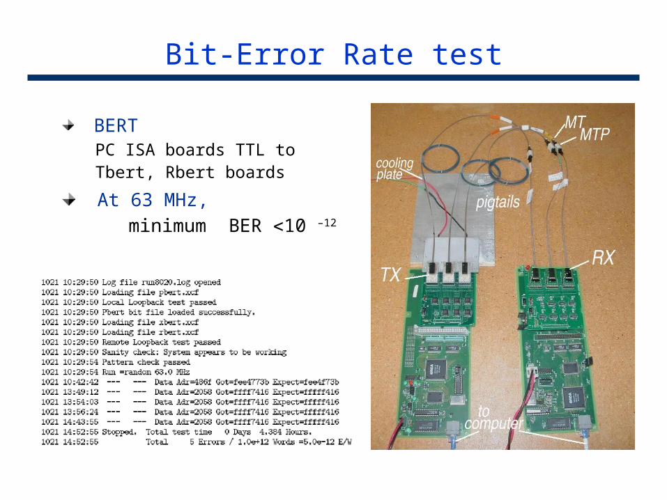
Bit-Error Rate test
BERTPC ISA boards TTL toTbert, Rbert boards
At 63 MHz, minimum BER 10 –12
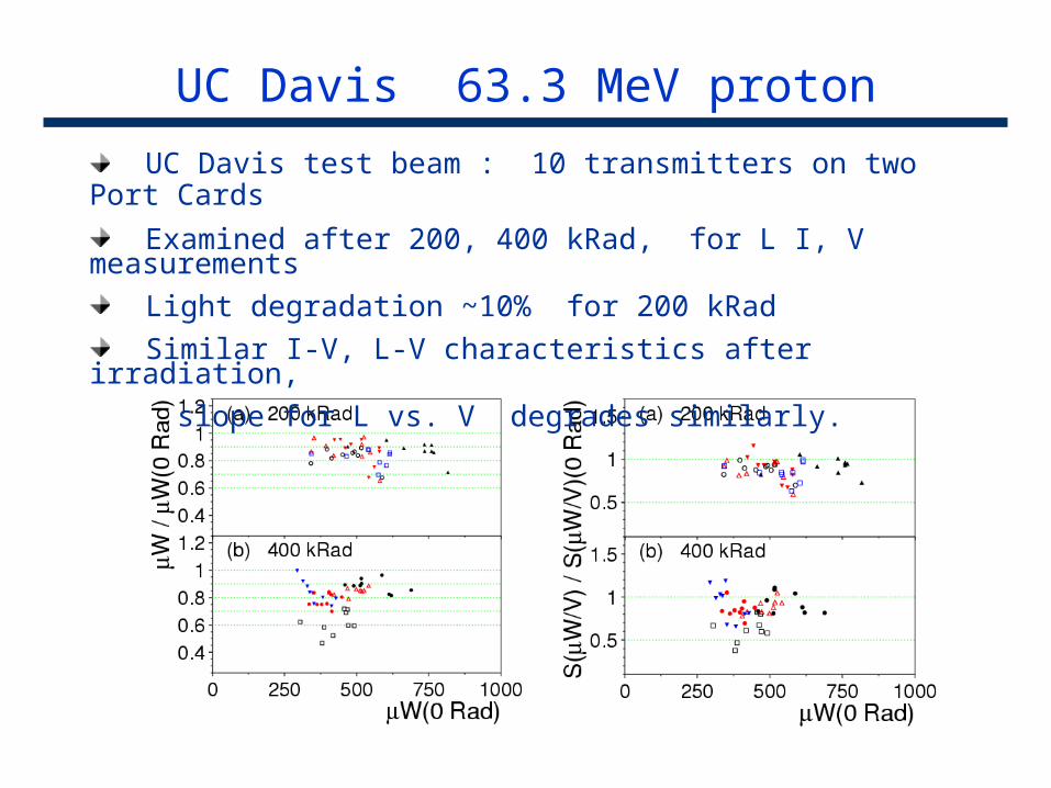
UC Davis 63.3 MeV proton
UC Davis test beam : 10 transmitters on two Port Cards
Examined after 200, 400 kRad, for L I, V measurements
Light degradation ~10% for 200 kRad
Similar I-V, L-V characteristics after irradiation,
slope for L vs. V degrades similarly.
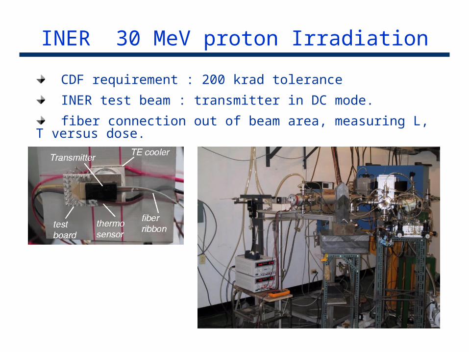
INER 30 MeV proton Irradiation
CDF requirement : 200 krad tolerance
INER test beam : transmitter in DC mode.
fiber connection out of beam area, measuring L, T versus dose.
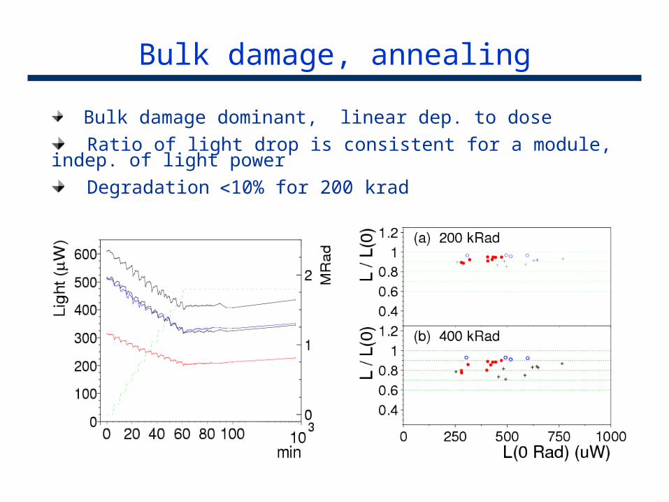
Bulk damage, annealing
Bulk damage dominant, linear dep. to dose
Ratio of light drop is consistent for a module, indep. of light power
Degradation 10% for 200 krad
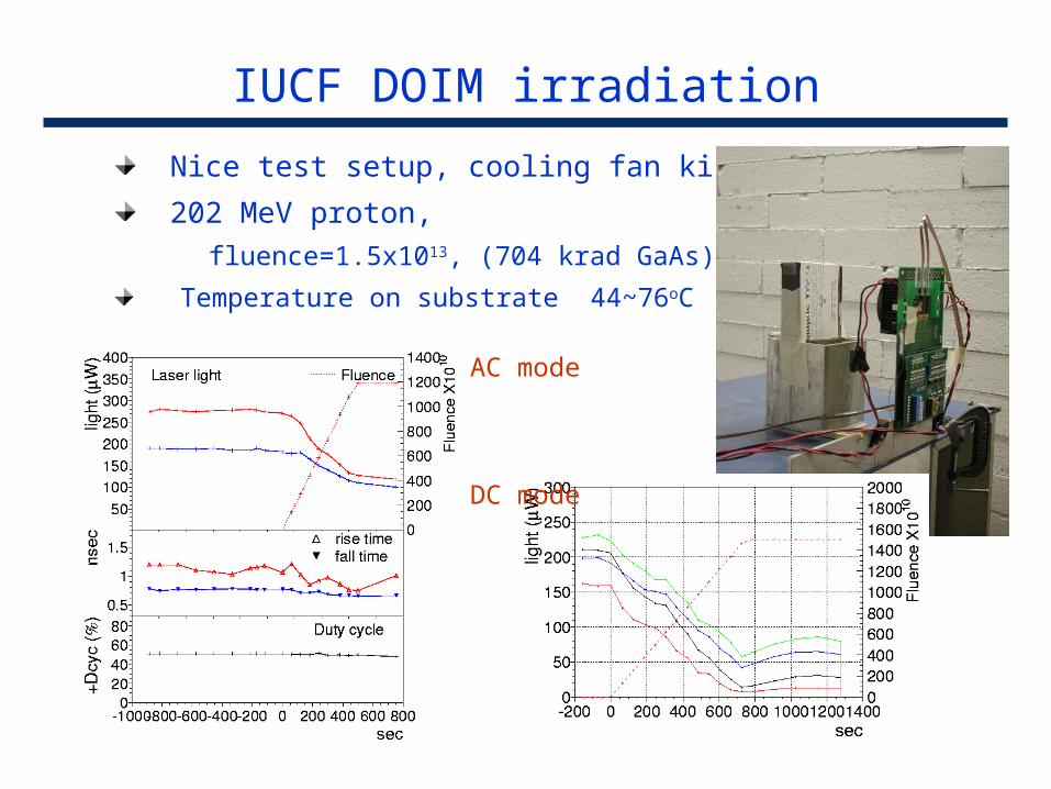
IUCF DOIM irradiation
Nice test setup, cooling fan killed
202 MeV proton,
fluence=1.5x10¹³, (704 krad GaAs)
Temperature on substrate 44~76oC
AC mode
DC mode
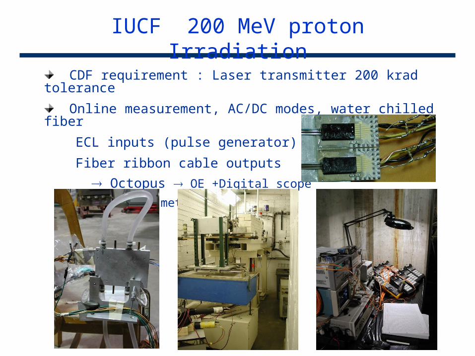
CDF requirement : Laser transmitter 200 krad tolerance
Online measurement, AC/DC modes, water chilled fiber
ECL inputs (pulse generator)
Fiber ribbon cable outputs
Octopus OE +Digital scope
DC PIN meters
IUCF 200 MeV proton Irradiation
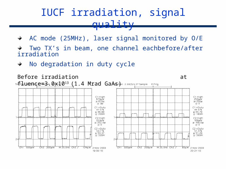
IUCF irradiation, signal quality
AC mode (25MHz), laser signal monitored by O/E
Two TX’s in beam, one channel eachbefore/after irradiation
No degradation in duty cycle
Before irradiation at fluence=3.0x10¹³ (1.4 Mrad GaAs)
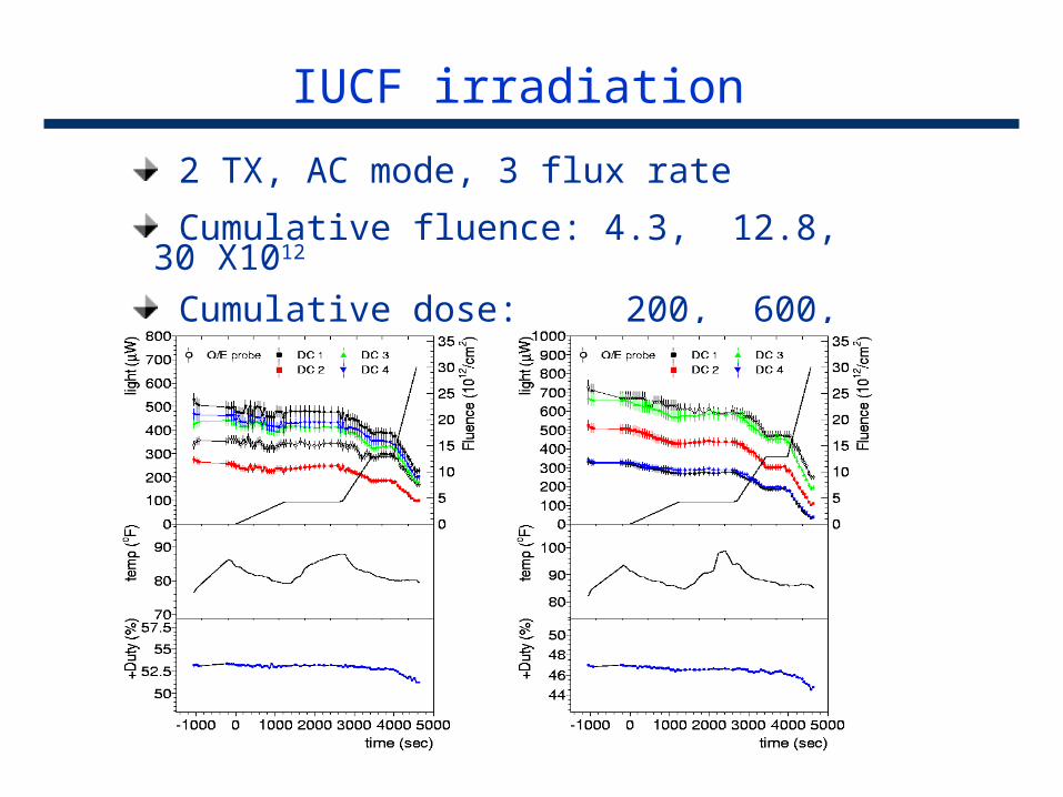
IUCF irradiation
2 TX, AC mode, 3 flux rate
Cumulative fluence: 4.3, 12.8, 30 X1012
Cumulative dose: 200, 600, 1400 krad
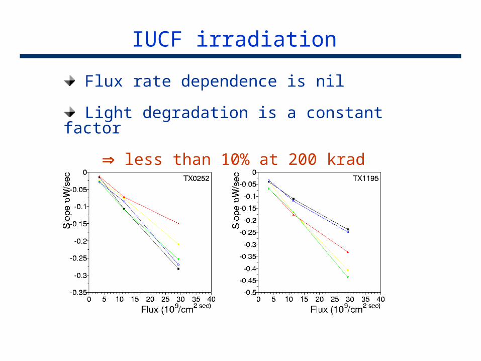
IUCF irradiation
Flux rate dependence is nil
Light degradation is a constant factor
less than 10% at 200 krad
IUCF irradiation
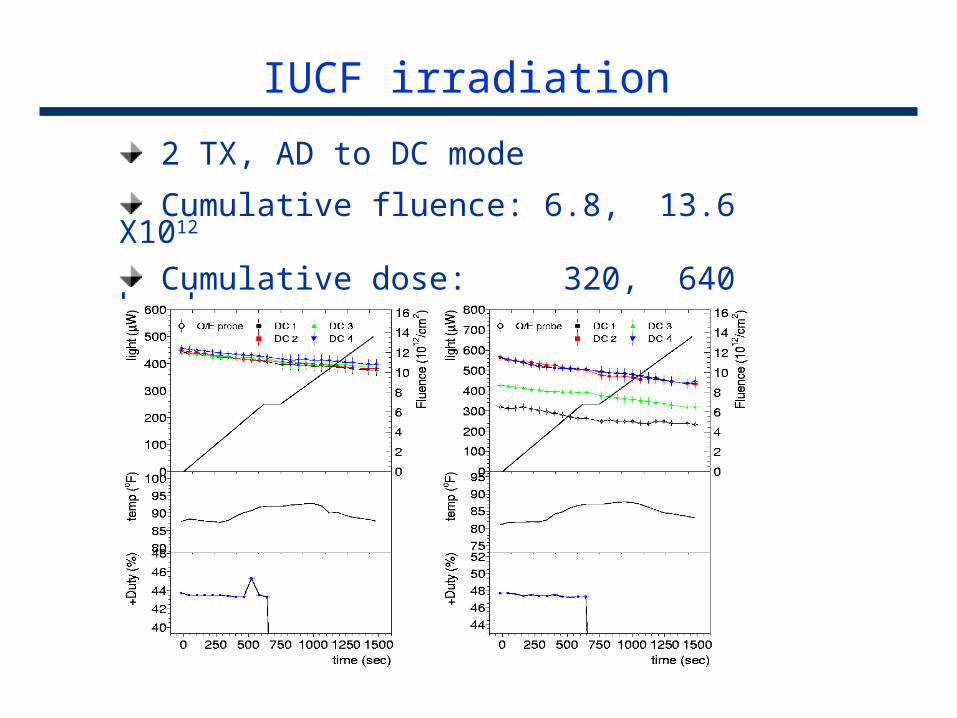
2 TX, AD to DC mode
Cumulative fluence: 6.8, 13.6 X10¹²
Cumulative dose: 320, 640 krad
IUCF irradiation
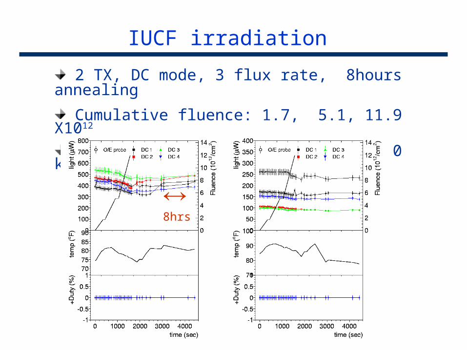
2 TX, DC mode, 3 flux rate, 8hours annealing
Cumulative fluence: 1.7, 5.1, 11.9 X10¹²
Cumulative dose: 80, 240, 560 krad
8hrs
Summary
DOIM : delicate, yet tough p-n junction application Edge-emitting laser sensitive to temperature Receiver delicate on ECL fiber cable is GLASS!!
Radiation tolerance is sufficient for CDF 10% degradation issue, can live on