Embed Size (px)
Citation preview
Article
Journal of Intelligent Material Systemsand Structures22(17) 1959–1973� The Author(s) 2011Reprints and permissions:sagepub.co.uk/journalsPermissions.navDOI: 10.1177/1045389X11420593jim.sagepub.com
Piezoelectric energy harvesting forcivil infrastructure system applications:Moving loads and surface strainfluctuations
Alper Erturk
AbstractThis article formulates the problem of vibration-based energy harvesting using piezoelectric transduction for civil infra-structure system applications with a focus on moving load excitations and surface strain fluctuations. Two approaches ofpiezoelectric power generation from moving loads are formulated. The first one is based on using a bimorph cantileverlocated at an arbitrary position on a simply supported slender bridge. The fundamental moving load problem is reviewedand the input to the cantilevered energy harvester is obtained to couple with the generalized electromechanical equa-tions for transient excitation. The second approach considers using a thin piezoceramic patch covering a region on thebridge. The transient electrical response of the surface patch to moving load excitation is derived in the presence of aresistive electrical load. The local way of formulating piezoelectric energy harvesting from two-dimensional surface strainfluctuations of large structures is also discussed. For a thin piezoceramic patch attached onto the surface of a large struc-ture, analytical expressions of the electrical power output are presented for generalized, harmonic, and white noise–typetwo-dimensional strain fluctuations. Finally, a case study is given to analyze a small piezoceramic patch for energyharvesting from surface strain fluctuations along with measured bridge strain data.
Keywordsenergy harvesting, piezoelectricity, vibration, strain, bridges, civil infrastructure
Introduction
Vibration-based energy harvesting has received growingattention over the last decade (Anton and Sodano,2007; Beeby et al., 2006; Cook-Chennault et al., 2008;Sodano et al., 2004). The basic motivation in thisresearch field is due to the reduced power requirementof small electronic components, such as the wirelesssensor networks used in passive and active monitoringapplications. If such wireless electronic components canbe powered by the vibrational energy available in theirenvironment, the maintenance costs for periodic batteryreplacement as well as the resulting chemical waste ofconventional batteries can be reduced dramatically.
The basic transduction mechanisms used forvibration-to-electric energy conversion are the electro-magnetic (Mann and Sims, 2009), electrostatic (Chiuand Tseng, 2008), and piezoelectric (Erturk and Inman,2009) transduction mechanisms. There have beenrecent articles focusing on the use of magnetostriction(Wang and Yuan, 2008) and electroactive polymers(Aureli et al., 2010) as well. Among these alternative
techniques for converting ambient vibrations into elec-tricity, piezoelectric transduction has been studied mostheavily (Anton and Sodano, 2007; Cook-Chennaultet al., 2008; Sodano et al., 2004) primarily due to theease of application and large power density of piezo-electric materials (Cook-Chennault et al., 2008). In thelast few years, researchers have investigated variousproblems related to modeling (Elvin and Elvin, 2009;Erturk and Inman, 2009; Renno et al., 2009; Shu et al.,2007; Stanton et al., 2010a, b) and applications (Antonand Sodano, 2007; Cook-Chennault et al., 2008;Sodano et al., 2004) of piezoelectric energy harvesters.
Recent research in the field of vibration-basedenergy harvesting has focused on modeling and exploit-ing nonlinear dynamics (Cottone et al., 2009; Erturk
Georgia Institute of Technology, G. W. Woodruff School of Mechanical
Engineering, Atlanta, GA 30332-0405, USA
Corresponding author:
Alper Erturk, Georgia Institute of Technology, 771 Ferst Drive, Love
Building, Room 126, Atlanta, GA 30332-0405, USA
Email: [email protected]
et al., 2009a; Erturk and Inman, 2011a; Mann andSims, 2009; Stanton et al., 2009, 2010a, b) as well asstochastic excitation (Adhikari et al., 2009; Daqaq,2010; Halvorsen, 2008; Litak et al., 2010; Scruggs,2009) of vibration-based energy harvesters. Althoughcivil infrastructure systems constitute a unique applica-tion field for energy harvesting due to the common useof battery-powered wireless sensors (Elvin et al., 2003,2006), such as the acoustic emission sensors (Ozevinet al., 2006; Shigeishi et al., 2001) used for structuralhealth prognosis in bridges, electromechanical model-ing of the fundamental civil engineering problems forvibration-based energy harvesting has not been dis-cussed in the literature. The aim of this article is to pro-vide an introduction to formulating such problems byfocusing on piezoelectric energy harvesting for typicalcivil infrastructure system applications. The problemsconsidered in this article are the moving load excitationof slender bridges and the surface strain fluctuations oflarge structures for piezoelectric power generation.
In the following sections, first a cantilevered piezoelec-tric energy harvester model is summarized for harmonic,arbitrary transient, and white noise excitations. After that,the fundamental moving load problem is visited for piezo-electric energy harvesting by considering two scenarios. Inthe first scenario, a cantilevered energy harvester is locatedat an arbitrary point on the bridge and a systematicapproach is discussed for relating the moving load prob-lem to the distributed parameter electromechanical equa-tions of the energy harvester. In the second scenario, apiezoceramic patch covers a region on the bridge and ana-lytical derivations are given to relate the piezoelectricpower output delivered from the patch to a resistive elec-trical load in terms of the moving load excitation. Afterthe fundamental moving load problem, the focus is placedon formulating the piezoelectric energy-harvesting prob-lem from two-dimensional surface strain fluctuations onlarge structures. Considering the orthogonal strain fluc-tuations as the excitation input to a rectangular piezocera-mic patch, analytical expressions for the electrical poweroutput are obtained for generalized, harmonic, and whitenoise inputs. Finally, a case study is given to analyze asmall piezoceramic patch for power generation from sur-face strain fluctuations. The power generation potential ofa small piezoelectric patch is discussed based on the strainmeasurements for a steel multigirder bridge.
Piezoelectric Energy Harvesting fromBase Excitation of Bimorph Cantilevers
This section summarizes the analytical derivations for abimorph cantilever located on and excited by vibrationsof a host civil engineering structure. The governing elec-tromechanical equations are given for a generalizedbase acceleration input, which are then solved for thesteady-state electromechanical response for harmonic
base acceleration. Following the harmonic excitationcase, the governing equations are expressed in the first-order form for transient base acceleration inputs (whichis the typical case in the moving load problem).Response to broadband random base vibration is alsocovered at the end of this section.
Governing Electromechanical Equations
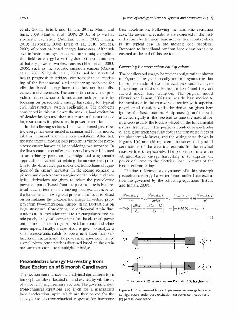
The cantilevered energy harvester configurations shownin Figure 1 are geometrically uniform symmetric thinbimorphs (made of two identical piezoceramic layersbracketing an elastic substructure layer) and they areexcited under base vibration. The original model(Erturk and Inman, 2009) assumes the base motion tobe translation in the transverse direction with superim-posed small rotation while the derivation given hereignores the base rotation. A tip mass (proof mass) isattached rigidly at the free end to tune the natural fre-quencies (usually the focus is placed on the fundamentalnatural frequency). The perfectly conductive electrodesof negligible thickness fully cover the transverse faces ofthe piezoceramic layers, and the wiring cases shown inFigures 1(a) and (b) represent the series and parallelconnections of the electrical outputs (to the externalresistive load), respectively. The problem of interest invibration-based energy harvesting is to express thepower delivered to the electrical load in terms of thebase acceleration input.
The linear electroelastic dynamics of a thin bimorphpiezoelectric energy harvester beam under base excita-tion are governed by the following equations (Erturkand Inman, 2009):
D∂4wrel(x, t)
∂x4+ cs
∂5wrel(x, t)
∂x4∂t+ cm
∂wrel(x, t)
∂t+ m
∂2wrel(x, t)
∂t2
�qv(t)dd(x)
dx� dd(x� L)
dx
� �= � m + Mtd(x� L)½ �a(t)
ð1Þ
Figure 1. Cantilevered bimorph piezoelectric energy harvesterconfigurations under base excitation: (a) series connection and(b) parallel connection.
1960 Journal of Intelligent Material Systems and Structures 22(17)
Ceqp
dv(t)
dt+
v(t)
Rl
+ q
ðL0
∂3wrel(x, t)
∂x2∂tdx = 0 ð2Þ
where a(t) is the translational base acceleration in thetransverse direction, wrel(x, t) is the vibration response(transverse displacement of the neutral axis relative tothe moving base at position x and time t), v(t) is thevoltage response (across the external resistive loadRl), D is the bending stiffness of the beam, m is themass per unit length of the beam, cm is the external(air) damping coefficient (mass proportional damp-ing), cs is the internal (strain rate or Kelvin–Voigt)damping coefficient of the composite structure (stiff-ness proportional damping), Mt is the tip mass, Ceq
p isthe equivalent capacitance of the piezoceramic layers,q is the electromechanical coupling term in the physi-cal coordinates, and d(x) is the Dirac delta function.The electromechanical coupling term is q = �e31bhpc ifthe layers are connected in series, whereas it isq = 2�e31bhpc if the layers are connected in parallel(where �e31 is the plane-stress piezoelectric stress con-stant, b is the width of the layers, and hpc is the dis-tance from the neutral axis to the center of eachpiezoceramic layer: hpc = (hp + hs)=2, where hp is thethickness of each piezoceramic layer and hs is thethickness of the substructure layer).
Based on the standard modal analysis procedure(Meirovitch, 2001), that is, assuming the system to be anormal-mode system,1 the vibration response isexpressed in terms of the modal coordinates hr(t) andthe mode shapes (mass-normalized eigenfunctions)fr(x) as
wrel(x, t) =X‘
r = 1
fr(x)hr(t) ð3Þ
where the eigenfunctions of a cantilevered Euler–Bernoulli beam with a tip mass attachment can beexpressed for the r-th vibration mode (of the undampedproblem) as
fr(x) = Cr coslr
Lx� cosh
lr
Lx + §r sin
lr
Lx� sinh
lr
Lx
� �� �ð4Þ
Here, §r is obtained from
§r =sinlr � sinh lr + lr
Mt
mLcoslr � cosh lrð Þ
coslr + cosh lr � lrMt
mLsin lr � sinhlrð Þ
ð5Þ
and Cr is a modal amplitude constant that is evaluatedby normalizing the eigenfunctions according to eitherone of the following orthogonality conditions:
ðL0
fs(x)mfr(x)dx + fs(L)Mtfr(L) +dfs(x)
dxIt
dfr(x)
dx
� �x = L
= drsðL0
fs(x)Dd4fr(x)
dx4dx� fs(x)D
d3fr(x)
dx3
� �x = L
+dfs(x)
dxDd2fr(x)
dx2
� �x = L
= v2r drs ð6Þ
Here, It is the mass moment of inertia of the tip massMt about the free end of the elastic beam and drs is theKronecker delta.2 Furthermore, vr is the undampednatural frequency of the r-th vibration mode in theshort-circuit conditions (i.e., Rl ! 0) given by
vr = l2r
ffiffiffiffiffiffiffiffiD
mL4
rð7Þ
where the eigenvalues of the system (lr for mode r) areobtained from the following transcendental equation:
1 + cosl cos hl + lMt
mLcosl sin hl� sin l cos hlð Þ
� l3It
mL3cosh l sinl + sinhl coslð Þ
+l4MtIt
m2L41� cosl cosh lð Þ= 0 ð8Þ
The electromechanically coupled ordinary differen-tial equations in the modal coordinates can be given bythe following equations (Erturk and Inman, 2009):
d2hr(t)
dt2+ 2zrvr
dhr(t)
dt+ v2
r hr(t)� ~urv(t) = sra(t) ð9Þ
Ceqp
dv(t)
dt+
v(t)
Rl
+X‘
r = 1
~ur
dhr(t)
dt= 0 ð10Þ
where zr is the modal mechanical damping ratio, ~ur isthe modal electromechanical coupling (~ur and Ceq
p areread from Table 1 depending on the series or parallelconnection of the piezoceramic layers), and sr is themodal forcing term expressed as
Table 1. Modal electromechanical coupling and equivalentcapacitance of a bimorph energy harvester for the series andparallel connections of the piezoceramic layers
Series connection Parallel connection
~ur �e31bhpcdfr(x)
dx
���x = L
2�e31bhpcdfr(x)
dx
���x = L
Ceqp
�eS33
bL
2hp
2�eS33
bL
hp
A. Erturk 1961
sr = � m
ðL0
fr(x)dx�Mtfr(L) ð11Þ
In Table 1, for a beam-like thin cantilever, the plane-stress piezoelectric stress constant �e31 can be given interms of the more commonly used piezoelectric strainconstant d31 as �e31 = d31=sE
11 (where sE11 is the elastic com-
pliance at constant electric field) and the plane-stress per-mittivity constant at constant strain is �es
33 = eT33 � d2
31=sE11
(where eT33 is the permittivity component at constant
stress). Note that, in Figure 1, the directions 1 and 3 arecoincident with the directions x and z, respectively.
Steady-State Response to Harmonic BaseAcceleration
If the base acceleration is harmonic of the forma(t) = A0ejvt (where A0 is the base acceleration ampli-tude, v is the excitation frequency, and j is the unitimaginary number), the steady-state analytical solutionfor the voltage-to-base acceleration frequency responsefunction (FRF) is obtained from Equations (9) and(10) as follows:
a(v) =v(t)
A0ejvt=
X‘
r = 1
�jv~ursr
v2r � v2 + j2zrvrv
1
Rl
+ jvCeqp +
X‘
r = 1
jv~u2r
v2r � v2 + j2zrvrv
ð12Þ
and the steady-state vibration response-to-base accel-eration FRF is
b(v, x) =wrel(x, t)
A0ejvt
=X‘
r = 1
sr � ~ur
P‘r = 1
jv~ursr
v2r�v2 + j2zrvrv
1Rl
+ jvCeqp +
P‘r = 1
jv~u2r
v2r�v2 + j2zrvrv
0BB@
1CCA fr(x)
v2r � v2 + j2zrvrv
2664
3775ð13Þ
For excitations close to a natural frequency, that is,v’vr, the multimode Equations (12) and (13) reduce tothe following single-mode equations:
a(v) =v(t)
A0ejvt
=�jvRl
~ursr
1 + jvRlCeqpð Þ v2
r � v2 + j2zrvrv�
+ jvRl~u2
r
ð14Þ
b(v, x) =wrel(x, t)
A0ejvt
=1 + jvRlC
eqp
�srfr(x)
1 + jvRlCeqpð Þ v2
r � v2 + j2zrvrv�
+ jvRl~u2
r
ð15Þ
where r = 1 for the frequently investigated case of exci-tation around the fundamental vibration mode toobtain the largest power output.
Response to Generalized Base Acceleration
In order to formulate the problem of piezoelectricenergy harvesting for generalized or transient accelera-tion inputs, Equations (9) and (10) can be given in thefirst-order form as
_u(1)r
_u(2)r
_u(3)
8<:
9=; =
u(2)r
�2zrvru(2)r � v2
r u(1)r + ~uru
(3) + sra(t)
�u(3)
RlCeqp�P‘r = 1
~uru(2)r
Ceqp
8>><>>:
9>>=>>;ð16Þ
where the overdot represents differentiation withrespect to time while the state variables are
u(1)r (t) = hr(t), u(2)
r (t) =dhr(t)
dt, u(3)(t) = v(t) ð17Þ
Note that the energy harvester beam has infinitelymany vibration modes (i.e., r = 1, 2, .). Depending onthe frequency content of the base acceleration inputand the modal frequencies of the harvester beam, it issufficient to consider a few vibration modes (say Nmodes), hence the dimension of the first-order repre-sentation reduces to 2N + 1.
If the initial displacement and velocity distributionsof the harvester beam are denoted by k(x) and m(x),respectively, and the initial voltage across the load isv0, the following summarizes the initial conditions inthe physical coordinates:
wrel(x, 0) = k(x),∂wrel(x, t)
∂t
����t = 0
= m(x), v(0) = v0 ð18Þ
The first orthogonality condition given by Equation(6) can be used to obtain the initial conditions for twoof the state variables as
u(1)r (0) = hr(0)
=
ðL0
k(x)mfr(x)dx + k(L)Mtfr(L) +dk(x)
dxIt
dfr(x)
dx
� �x = L
ð19Þ
u(2)r (0) =
dhr(t)
dt
����t = 0
=
ðL0
m(x)mfr(x)dx + m(L)Mtfr(L) +dm(x)
dxIt
dfr(x)
dx
� �x = L
ð20Þ
1962 Journal of Intelligent Material Systems and Structures 22(17)
and the initial condition for the third state variable issimply
u(3)(0) = v(0) = v0 ð21Þ
Having the first-order form of the electromechanicalequations and the initial conditions of the state vari-ables (the initial conditions are often zero), an appro-priate ordinary differential equation solver can beemployed to solve for the response to arbitrary accel-eration inputs.
Response to Broadband Base Acceleration of WhiteNoise Type
For a linear random process (Newland, 1993), if thepower spectral density (PSD) of the base accelerationa(t) is Sa(v), the PSD of the voltage output is obtainedfrom
Sv(v) = a(v)j j2 Sa(v) ð22Þ
where a(v) is given by Equation (12). The inverseFourier transform of the PSD of the voltage output isits autocorrelation function:
Rv(t) =
�
Sv(v)ejvtdv =
�
a(v)j j2 Sa(v)ejvtdv ð23Þ
For the case of ideal white noise excitation(Newland, 1993), the input PSD covers the entire fre-quency band with constant amplitude, yielding
Rv(t) = S0
�
a(v)j j2 ejvtdv ð24Þ
where S0 is the constant PSD of the base accelerationa(t).
The mean square value of the voltage output isrelated to its autocorrelation function based on the fol-lowing expression:
E v2(t)�
= Rv(0) =
�
a(v)j j2 Sa(v)dv = S0
�
a(v)j j2dv
ð25Þ
where the ideal white noise spectral density is substi-tuted. Recalling that the electrical power output is sim-ply v2(t)=Rl, the expected value of the power outputbecomes
E P(t)½ �= S0
Rl
�
a(v)j j2dv ð26Þ
Therefore, the exact analytical solution for theexpected value of the power output is obtained from
E P(t)½ �= S0
Rl
�
P‘r = 1
�jv~ursr
v2r�v2 + j2zrvrv
1Rl
+ jvCeqp +
P‘r = 1
jv~u2r
v2r�v2 + j2zrvrv
��������
��������
2
dv ð27Þ
which can be simplified dramatically by consideringonly the fundamental vibration mode (based on the rea-soning that the highest energy is around the first natu-ral frequency):
E P(t)�
=S0
Rl
�
�jvRl~u1s1
1 + jvRlCeqpð Þ v2
1 � v2 + j2z1v1v�
+ jvRl~u2
1
����������2
dv
ð28Þ
Using the integration relations in Newland’s appen-dix (Newland, 1993) gives
E P(t)�
=pS0Rl
~u21s2
1
Rl~u2
1 + 2z1v1 1 + R2l~u2
1Ceqp
� + 2z1 + RlC
eqp v1ð Þ RlC
eqp v1ð Þ
� ð29Þ
which is analogous to the lumped parameter derivationsgiven by Halvorsen (2008) and Adhikari et al. (2009).
Piezoelectric Energy Harvesting fromMoving Load Excitation
The problem of piezoelectric power generation frommoving load excitation is formulated for two scenariosby focusing on a slender bridge3 configuration (for pos-sible applications to high-span highway bridges). Theproblems considered in the following are (1) energyharvesting from the vibrations of a piezoelectric cantile-ver located at an arbitrary point on the bridge and (2)energy harvesting using a thin piezoceramic patch cov-ering an arbitrary region on the bridge.
Cantilevered Piezoelectric Energy Harvester Locatedon a Slender Bridge
The uniform slender bridge shown in Figure 2 is underthe excitation of a transversely applied constant-amplitude point load P (representing a vehicle) movingat a constant speed �v. The equation of motion govern-ing the vibrations of the bridge is
�D∂4 �w(�x, t)
∂�x4+ �cs
∂5 �w(�x, t)
∂�x4∂t+ �cm
∂�w(�x, t)
∂t+ �m
∂2 �w(�x, t)
∂t2= Pd(�x� �vt)
ð30Þ
where �w(�x, t) is the vibration response of the bridge(transverse displacement of the neutral axis at posi-tion �x and time t), �D is the bending stiffness, �m is the
A. Erturk 1963
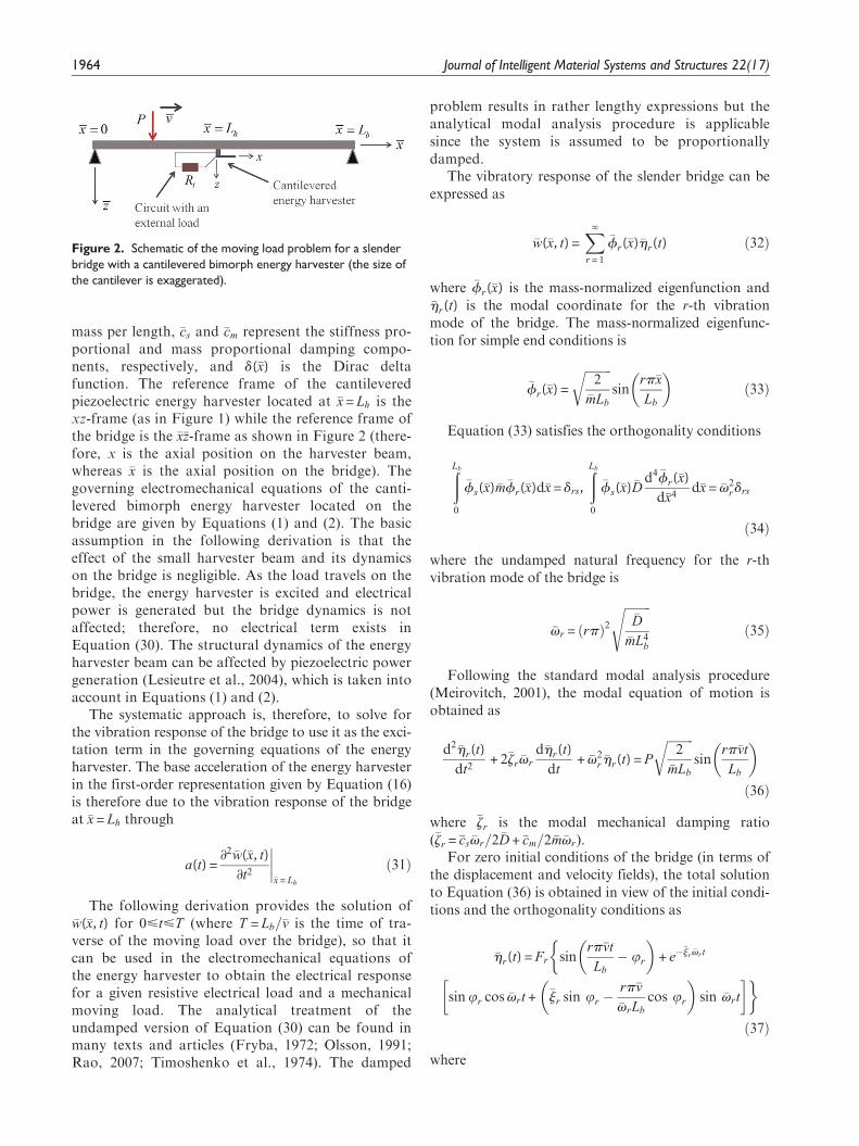
mass per length, �cs and �cm represent the stiffness pro-portional and mass proportional damping compo-nents, respectively, and d(�x) is the Dirac deltafunction. The reference frame of the cantileveredpiezoelectric energy harvester located at �x = Lh is thexz-frame (as in Figure 1) while the reference frame ofthe bridge is the �x�z-frame as shown in Figure 2 (there-fore, x is the axial position on the harvester beam,whereas �x is the axial position on the bridge). Thegoverning electromechanical equations of the canti-levered bimorph energy harvester located on thebridge are given by Equations (1) and (2). The basicassumption in the following derivation is that theeffect of the small harvester beam and its dynamicson the bridge is negligible. As the load travels on thebridge, the energy harvester is excited and electricalpower is generated but the bridge dynamics is notaffected; therefore, no electrical term exists inEquation (30). The structural dynamics of the energyharvester beam can be affected by piezoelectric powergeneration (Lesieutre et al., 2004), which is taken intoaccount in Equations (1) and (2).
The systematic approach is, therefore, to solve forthe vibration response of the bridge to use it as the exci-tation term in the governing equations of the energyharvester. The base acceleration of the energy harvesterin the first-order representation given by Equation (16)is therefore due to the vibration response of the bridgeat �x = Lh through
a(t) =∂2 �w(�x, t)
∂t2
�����x = Lh
ð31Þ
The following derivation provides the solution of�w(�x, t) for 0<t<T (where T = Lb=�v is the time of tra-verse of the moving load over the bridge), so that itcan be used in the electromechanical equations ofthe energy harvester to obtain the electrical responsefor a given resistive electrical load and a mechanicalmoving load. The analytical treatment of theundamped version of Equation (30) can be found inmany texts and articles (Fryba, 1972; Olsson, 1991;Rao, 2007; Timoshenko et al., 1974). The damped
problem results in rather lengthy expressions but theanalytical modal analysis procedure is applicablesince the system is assumed to be proportionallydamped.
The vibratory response of the slender bridge can beexpressed as
�w(�x, t) =X‘
r = 1
�fr(�x)�hr(t) ð32Þ
where �fr(�x) is the mass-normalized eigenfunction and�hr(t) is the modal coordinate for the r-th vibrationmode of the bridge. The mass-normalized eigenfunc-tion for simple end conditions is
�fr(�x) =
ffiffiffiffiffiffiffiffiffi2
�mLb
rsin
rp�x
Lb
� �ð33Þ
Equation (33) satisfies the orthogonality conditions
ðLb
0
�fs(�x)�m�fr(�x)d�x = drs,
ðLb
0
�fs(�x)�Dd4 �fr(�x)
d�x4d�x = �v2
r drs
ð34Þ
where the undamped natural frequency for the r-thvibration mode of the bridge is
�vr = rpð Þ2ffiffiffiffiffiffiffiffiffi
�D
�mL4b
sð35Þ
Following the standard modal analysis procedure(Meirovitch, 2001), the modal equation of motion isobtained as
d2�hr(t)
dt2+ 2�zr �vr
d�hr(t)
dt+ �v2
r �hr(t) = P
ffiffiffiffiffiffiffiffiffi2
�mLb
rsin
rp�vt
Lb
� �ð36Þ
where �zr is the modal mechanical damping ratio(�zr = �cs �vr=2�D + �cm=2�m�vr).
For zero initial conditions of the bridge (in terms ofthe displacement and velocity fields), the total solutionto Equation (36) is obtained in view of the initial condi-tions and the orthogonality conditions as
�hr(t) = Fr sinrp�vt
Lb
� ur
� �+ e�
�jr �vr t
�
sinur cos �vrt + �jr sin ur �rp�v
�vrLb
cos ur
� �sin �vrt
� ��ð37Þ
where
Figure 2. Schematic of the moving load problem for a slenderbridge with a cantilevered bimorph energy harvester (the size ofthe cantilever is exaggerated).
1964 Journal of Intelligent Material Systems and Structures 22(17)
Fr = P
ffiffiffiffiffiffiffiffiffiffiffiffiffiffiffiffiffiffiffiffiffiffiffiffiffiffiffiffiffiffiffiffiffiffiffiffiffiffiffiffiffiffiffiffiffiffiffiffiffiffiffiffiffiffiffiffiffiffiffiffiffiffiffiffiffiffiffiffiffiffiffiffi2
�mLb �v2r � rp�v
Lb
�2� �2
+ 2�zr �vrrp�vLb
�2
( )vuuuut ,
ur = tan�1
2�zr �vrrp�vLb
�v2r � rp�v
Lb
�2
0B@
1CA ð38Þ
The vibration response is then4
�w(�x, t) =X‘
r = 1
�fr(�x)Fr sinrp�vt
Lb
� ur
� �+ e�
�jr �vrt
�
sin ur cos �vrt + �jr sin ur �rp�v
�vrLb
cos ur
� �sin �vrt
� ��ð39Þ
Therefore, the acceleration input to the cantileveredenergy harvester located at �x = Lh is
a(t) =X‘
r = 1
�fr Lhð ÞFr
d2
dt2sin
rp�vt
Lb
� ur
� �+ e�
�jr �vrt
�
sin ur cos �vrt + �jr sin ur �rp�v
�vrLb
cos ur
� �sin �vrt
� ��ð40Þ
which can be further expanded after the application ofthe differentiation. The transverse acceleration given byEquation (40) is the input to the first-order representa-tion of the energy harvester equations given byEquation (16).
The nature of the bridge response strongly dependson the speed of the moving load. Fryba (1972) nor-malizes the p�v=Lb term with respect to the fundamen-tal natural frequency of the bridge and defines thedimensionless parameter a = p�v=�v1Lb. Olsson (1991)reports that a = 1 typically corresponds to a vehiclespeed of 400–1500 km/h depending on the structuralflexibility of the bridge, defining a conservative upperlimit for most practical purposes. For the fast vehiclespeed of a = 1, the midspan (�x = Lb=2) reaches its maxi-mum deflection (implying a quarter cycle of vibra-tion) after the vehicle exits the bridge (Olsson, 1991).Simulations given in Fryba (1972) show that themaximum dynamic deflection is obtained for0:5 < a < 0:7. For large values of a, the deflectionrapidly tends to zero, whereas it converges to the sta-tic deflection for low values of a.
Large-span highway bridges are usually lightlydamped structures (Fryba, 1972). Moreover, if thevehicle speed satisfies a� 1 (i.e., �v� �v1Lb=p), theresponse is dominated by the fundamental vibrationmode of the bridge. Therefore, taking only the firstterm (r = 1) in the summation of Equation (39) due tolow vehicle speed and setting �j1 � 1 due to light damp-ing of the bridge simplifies Equation (39) to
�w(�x, t) ffi �f1(�x)F1 sinp�vt
Lb
=2P
�m�v21Lb
sinpLh
Lb
sinp�vt
Lb
ð41Þ
Thus, the dynamic response of the bridge is reducedto simple harmonic motion as a first approximation.Consequently, the acceleration input to the cantileveredenergy harvester is also harmonic due to
a(t) =∂2 �w(�x, t)
∂t2
�����x = Lh
ffi �f1 Lhð ÞF1
d2
dt2sin
p�vt
Lb
� �
=� 2Pp2�v2
�m�v21L3
b
sinpLh
Lb
sinp�vt
Lb
ð42Þ
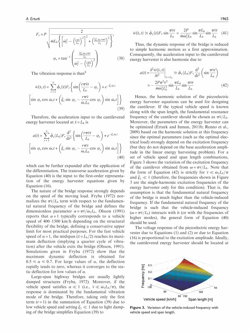
Hence, the harmonic solution of the piezoelectricenergy harvester equations can be used for designingthe cantilever. If the typical vehicle speed is knownalong with the span length, the fundamental resonancefrequency of the cantilever should be chosen as p�v=Lb.Moreover, the parameters of the energy harvester canbe optimized (Erturk and Inman, 2011b; Renno et al.,2009) based on the harmonic solution at this frequencysince the optimal parameters (such as the optimal elec-trical load) strongly depend on the excitation frequency(but they do not depend on the base acceleration ampli-tude in the linear energy harvesting problem). For aset of vehicle speed and span length combinations,Figure 3 shows the variation of the excitation frequencyof the cantilever obtained from v = p�v=Lb. Note thatthe form of Equation (42) is strictly for �v� �v1Lb=p
and �j1 � 1 (therefore, the frequencies shown in Figure3 are the single-harmonic excitation frequencies of theenergy harvester only for this condition). That is, theassumption is that the fundamental natural frequencyof the bridge is much higher than the vehicle-inducedfrequency. If the fundamental natural frequency of thebridge is such that the vehicle-induced frequency(v = p�v=Lb) interacts with it (or with the frequencies ofhigher modes), the general form of Equation (40)should be used.
The voltage response of the piezoelectric energy har-vester due to Equations (1) and (2) or due to Equation(16) is proportional to the excitation amplitude. Ideally,the cantilevered energy harvester should be located at
Figure 3. Variation of the vehicle-induced frequency withvehicle speed and span length.
A. Erturk 1965
the position of the maximum dynamic response on thebridge. The position of the maximum dynamic responseis related to the eigenfunction expression given byEquation (33). Expectedly, if the response of the bridgeis dominated by the fundamental vibration mode (forlow vehicle speeds), the ideal location is obtained fromEquation (33) as the midspan of the bridge (�x = Lb=2). Ifthe bridge response is dominated by higher vibrationmodes, one should avoid locating the energy harvesterat the nodal positions of the respective eigenfunctionsand use the antinodal positions if the typical speeds inthe traffic (therefore, the excitation frequencies and theexpected mode shapes) are known.
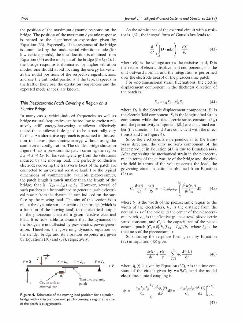
Thin Piezoceramic Patch Covering a Region on aSlender Bridge
In many cases, vehicle-induced frequencies as well asbridge natural frequencies can be too low to excite a rel-atively stiff energy-harvesting cantilever effectivelyunless the cantilever is designed to be structurally veryflexible. An alternative approach is presented in this sec-tion to harvest piezoelectric energy without using thecantilevered configuration. The slender bridge shown inFigure 4 has a piezoceramic patch covering the regionLh1 < �x < Lh2 for harvesting energy from the vibrationsinduced by the moving load. The perfectly conductiveelectrodes covering the transverse faces of the patch areconnected to an external resistive load. For the typicaldimensions of commercially available piezoceramics,the patch length is much smaller than the length of thebridge, that is, Lh2 � Lh1ð Þ � Lb. However, several ofsuch patches can be combined to generate usable electri-cal power from the dynamic strain induced on the sur-face by the moving load. The aim of this section is torelate the dynamic surface strain of the bridge (which isa function of the moving load) to the electrical outputof the piezoceramic across a given resistive electricalload. It is reasonable to assume that the dynamics ofthe bridge are not affected by piezoelectric power gener-ation. Therefore, the governing dynamic equation ofthe slender bridge and its vibration response are givenby Equations (30) and (39), respectively.
As the admittance of the external circuit with a resis-tor is 1=Rl, the integral form of Gauss’s law leads to
d
dt
ðA
D � ndA
0@
1A=
v(t)
Rl
ð43Þ
where v(t) is the voltage across the resistive load, D isthe vector of electric displacement components, n is theunit outward normal, and the integration is performedover the electrode area A of the piezoceramic patch.
For one-dimensional strain fluctuations, the electricdisplacement component in the thickness direction ofthe patch is
D3 = �e31S1 + �eS33E3 ð44Þ
where D3 is the electric displacement component, E3 isthe electric field component, S1 is the longitudinal straincomponent while the piezoelectric stress constant (�e31)and the permittivity component (�eS
33) are as defined ear-lier (the directions 1 and 3 are coincident with the direc-tions �x and �z in Figure 4).
Since the electrodes are perpendicular to the trans-verse direction, the only nonzero component of theinner product in Equation (43) is due to Equation (44).After expressing the mechanical strain in the piezocera-mic in terms of the curvature of the bridge and the elec-tric field in terms of the voltage across the load, thegoverning circuit equation is obtained from Equation(43) as
Cp
dv(t)
dt+
v(t)
Rl
= � �e31hpcbp
ðLh2
Lh1
∂3 �w(�x, t)
∂�x2∂td�x ð45Þ
where bp is the width of the piezoceramic (equal to thewidth of the electrodes), hpc is the distance from theneutral axis of the bridge to the center of the piezocera-mic patch, �e31 is the effective (plane-stress) piezoelectricstress constant, and Cp is the capacitance of the piezo-ceramic patch (Cp = �eS
33bp(Lh2 � Lh1)=hp, where hp is thethickness of the piezoceramic).
Substituting the response form given by Equation(32) in Equation (45) gives
dv(t)
dt+
v(t)
t=X‘
r = 1
cr
d�hr(t)
dtð46Þ
where �hr(t) is given by Equation (37), t is the time con-stant of the circuit given by t = RlCp, and the modalelectromechanical coupling is
cr = � �e31hpcbp
Cp
ðLh2
Lh1
d2 �fr(�x)
d�x2d�x = � �e31hpcbp
Cp
d�fr(�x)
d�x
�����x = Lh2
�x = Lh1
ð47Þ
Figure 4. Schematic of the moving load problem for a slenderbridge with a thin piezoceramic patch covering a region (the sizeof the patch is exaggerated).
1966 Journal of Intelligent Material Systems and Structures 22(17)
Equation (46) can be solved by using the integratingfactor et=t, yielding
v(t) = e�tt
ðe
tt
X‘
r = 1
cr
d�hr(t)
dtdt ð48Þ
where the initial voltage is assumed to be zero.Therefore, for the external resistive load Rl, the electri-cal power output is
P(t) =1
Rl
e�tt
ðe
tt
X‘
r = 1
cr
d�hr(t)
dtdt
" #2
ð49Þ
The excitation of the piezoceramic patch (and hence,its electrical output) is proportional to the dynamicstrain field induced over the region it covers. FromEquation (47), the optimal region to cover is the regionof maximum curvature, so that cr is maximized for agiven vibration mode r. Therefore, for vibrations withthe fundamental mode of the bridge (r = 1), one shouldprefer covering the region (Lb � Lp)=2 < �x <
(Lb + Lp)=2 (where Lp is the length of the patch). Forvibrations with higher modes, covering the inflectionpoints (strain nodes (Erturk et al., 2009b)) of the bridgewith a single patch results in cancellation of the electri-cal output. Nevertheless, in practice, it is necessary touse several patches (due to their size limitations) forcovering a significant region on the bridge and one sim-ply needs to consider the phases of the electrical out-puts before combining them in the circuit to avoidcancellations (Erturk et al., 2009b).
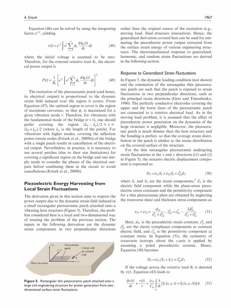
Piezoelectric Energy Harvesting fromLocal Strain Fluctuations
The derivation given in this section aims to express thepower output due to the dynamic strain field induced ina small rectangular piezoceramic patch attached onto avibrating host structure (Figure 5). Therefore, the prob-lem considered here is a local and two-dimensional wayof treating the problem of the previous section. Theinputs in the following derivation are the dynamicstrain components in two perpendicular directions
rather than the original source of the excitation (e.g.,moving load, fluid–structure interaction). Hence, thegeneralized derivation covered here can be used for esti-mating the piezoelectric power output extracted fromthe surface strain energy of various engineering struc-tures. The electromechanical response to generalized,harmonic, and random strain fluctuations are derivedin the following section.
Response to Generalized Strain Fluctuations
In Figure 5, the dynamic loading condition (not shown)and the orientation of the rectangular thin piezocera-mic patch are such that the patch is exposed to strainfluctuations in two perpendicular directions, such asthe principal strain directions (Gere and Timoshenko,1990). The perfectly conductive electrodes covering theupper and the lower faces of the piezoceramic patchare connected to a resistive electrical load. As in themoving load problem, it is assumed that the effect ofpiezoelectric power generation on the dynamics of thelarge structure is negligible. Moreover, the piezocera-mic patch is much thinner than the host structure andthe bonding is perfect, so that the average strain distri-bution in the patch is similar to the strain distributionon the covered surface of the structure.
For the thin rectangular piezoceramic undergoingstrain fluctuations in the x and y directions ((1) and (2)in Figure 5), the nonzero electric displacement compo-nent is expressed as
D3 = �e31S1 + �e32S2 + �eS33E3 ð50Þ
where S1 and S2 are the strain components,5 E3 is theelectric field component while the plane-stress piezo-electric stress constants and the permittivity componentfor a thin piezoceramic plate are obtained by neglectingthe transverse shear and thickness stress components as
�e31 = �e32 =d31
sE11 + sE
12
, �eS33 = eT
33 �2d2
31
sE11 + sE
12
ð51Þ
Here, d31 is the piezoelectric strain constant, sE11 and
sE12 are the elastic compliance components at constantelectric field, and eT
33 is the permittivity component atconstant stress. In Equation (51), the symmetry oftransverse isotropy about the z-axis is applied byassuming a poled piezoelectric ceramic. Hence,Equation (50) becomes
D3 = �e31 S1 + S2ð Þ+ �eS33E3 ð52Þ
If the voltage across the resistive load Rl is denotedby v(t), Equation (43) leads to
dv(t)
dt+
v(t)
t=
�e31
Cp
ðA
∂
∂tS1(x, y, t) + S2(x, y, t)½ �dA ð53ÞFigure 5. Rectangular thin piezoceramic patch attached onto a
large civil engineering structure for power generation from two-dimensional surface strain fluctuations.
A. Erturk 1967
where t = RlCp is the time constant and Cp = �eS33A=hp is
the capacitance of the piezoceramic patch (where hp isits thickness and A is the electrode area).
For the space-dependent strain componentsS1(x, y, t) and S2(x, y, t), the solution of the voltageresponse is
v(t) =�e31
Cp
e�tt
ðe
tt
ðA
∂
∂tS1(x, y, t) + S2(x, y, t)½ �dA
8<:
9=;dt ð54Þ
and the power output is obtained from
P(t) =1
Rl
�e31
Cp
e�tt
ðe
tt
ðA
∂
∂tS1(x, y, t) + S2(x, y, t)½ �dA
8<:
9=;dt
* +2
ð55Þ
In order to maximize the spatial integrand inEquation (55), one should avoid covering the inflectionlines of the host surface (where the strain componentschange sign) with a single patch.
If the strain field in each direction of the piezocera-mic patch is homogenous (so that S1(t) and S2(t) arespace-independent), the right-hand side of Equation(53) is simplified to give
dv(t)
dt+
v(t)
t=
�e31A
Cp
d
dtS1(t) + S2(t)½ � ð56Þ
yielding the power output of
P(t) =1
Rl
�e31A
Cp
e�tt
ðe
ttd
dtS1(t) + S2(t)½ �dt
� �2
ð57Þ
Steady-State Response to Harmonic StrainFluctuations
Consider the case where the dynamic strain componentsare harmonic in time at the same frequency:
S1(t) = ~S1ejvt, S2(t) = ~S2ejvt ð58Þ
where ~S1 and ~S2 are the strain values (which might becomplex valued to account for a phase difference), v isthe excitation frequency, and j is the unit imaginarynumber. In practice, each of the strain componentscould also have a DC (static) component, which has nocontribution to the alternating voltage output of thepiezoceramic patch at steady state.
The steady-state voltage output is obtained fromEquation (56) as
v(t) = jv�e31A ~S1 + ~S2
� jvCp +
1
Rl
� ��1
ejvt ð59Þ
Hence the steady-state power amplitude is
P =v2�e2
31A2 ~S1 + ~S2
� 2Rl
1 + v2R2l C2
p
ð60Þ
which can be used to find the optimal electrical load as
∂P
∂Rl
����Rl = R
opt
l
= 0! Roptl =
1
vCp
ð61Þ
Therefore, the maximum power output is simply
Pmax = PjRl = Ropt
l=
v�e231A2 ~S1 + ~S2
� 2
2Cp
ð62Þ
Response to Broadband Strain Fluctuations of WhiteNoise Type
For harmonic strain fluctuations in two perpendiculardirections, one can define the following electromechani-cal FRF using Equation (59):
x(v) =v(t)
jv ~S1 + ~S2
� ejvt
=�e31ARl
1 + jvRlCp
ð63Þ
which is the frequency-domain transfer function thatrelates the harmonic voltage response to the harmonicstrain-rate resultant at steady state.
If the PSD of the white noise-type strain-rate resul-tant is given by Ss(v) = S0, after following steps similarto those given for the base excitation problem, theexpected value of the power output can be obtained as
E P(t)½ �= 1
Rl
�
x(v)j j2Ss(v)dv
=S0
Rl
�
�e31ARl
1 + jvRlCp
��������2
dv =S0p �e31Að Þ2
Cp
ð64Þ
Remarkably, for an ideal white noise–type strain-rate resultant, the expected value of the electrical poweroutput extracted from the piezoceramic patch does notdepend on the external load resistance. The power out-put in both harmonic and white noise excitations isproportional to �e2
31=Cp due to Equations (62) and (64),respectively (where Cp}�eS
33). Therefore, the piezoelectricmaterial should be chosen to maximize �e2
31=�eS33 for har-
vesting energy from surface strain fluctuations using apatch.
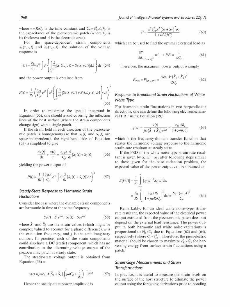
Strain Gage Measurements and StrainTransformations
In practice, it is useful to measure the strain levels onthe surface of the host structure to estimate the poweroutput using the foregoing derivations prior to bonding
1968 Journal of Intelligent Material Systems and Structures 22(17)
a piezoceramic patch onto the host structure. Thedirections of principal strain components and the waythey change in time (if they do) can also be checked.Usually, strain gage rosettes are employed for strainmeasurements and they consist of multiple gagesoriented at a fixed angle with respect to each other.Figure 6 shows the schematic of a rectangular rosetteconfiguration (where the angle between the gages is45�). In general, at least three independent strain read-ings are required to define the two-dimensional stateof strain assuming that no other information is avail-able. The rectangular rosette configuration shown inFigure 6 gives three simultaneous strain measurementsSA, SB, and SC in A, B, and C directions, respectively.The directions of the principal strain components (S1
and S2) are denoted by 1 and 2.Based on Mohr’s circle (Gere and Timoshenko,
1990), the principal strain components are obtainedfrom the following strain transformation:
S1, 2 =SA + SC
26
1ffiffiffi2p
ffiffiffiffiffiffiffiffiffiffiffiffiffiffiffiffiffiffiffiffiffiffiffiffiffiffiffiffiffiffiffiffiffiffiffiffiffiffiffiffiffiffiffiffiffiffiffiSA � SBð Þ2 + SB � SCð Þ2
qð65Þ
and the angle between gage A and the direction of posi-tive S1 is
u =1
2tan�1 SA � 2SB + SC
SA � SC
� �ð66Þ
Equations (65) and (66) give an idea regarding howthe strain levels and the direction of principal strainschange in time if the loading and structural conditionsresult in such variations. It is useful noticing fromEquation (65) that
S1 + S2 =SA + SC
2+
SA + SC
2= SA + SC ð67Þ
which implies that the strain resultant of two arbitrarybut orthogonal directions (SA + SC) is equal to that ofthe principal strain directions (S1 + S2). Although deter-mining the two-dimensional strain state on the surfacerequires three independent strain measurements, two
orthogonal strain measurements are sufficient to esti-mate the resultant of the principal strain componentsand, therefore, the resulting power output for a rectan-gular patch oriented in the principal strain directions.
Case Study for Piezoelectric EnergyHarvesting from Surface StrainFluctuations
Analysis of a Piezoceramic Patch forTwo-Dimensional Strain Fluctuations
This section analyzes a piezoceramic patch for piezo-electric power generation from surface strain fluctua-tions. The thin patch considered here is a 30 330 3
0.2 mm3 lead zirconate titanate PZT-5A square piezo-ceramic plate with d31 = 2171 pm/V, sE
11 =16:4pm2=N,sE
12 =�5:74pm2=N, eT33 = 15:05 nF=m (yielding �e31 =
�16 C=m2 and �eS33 = 9:57 nF=m). If two conductive
electrodes of negligible thickness cover the oppositefaces completely, the capacitance of the patch can becalculated as Cp = 43 nF. In the following simulations,it is assumed that the strain fluctuation is harmonic atthe same frequency in both orthogonal strain direc-tions, and the strain field in the patch is homogeneous.The input parameters required to predict the maximumpower amplitude in Equation (62) are then the strainvalues (~S1 and ~S2) and the frequency of harmonicfluctuation (v).
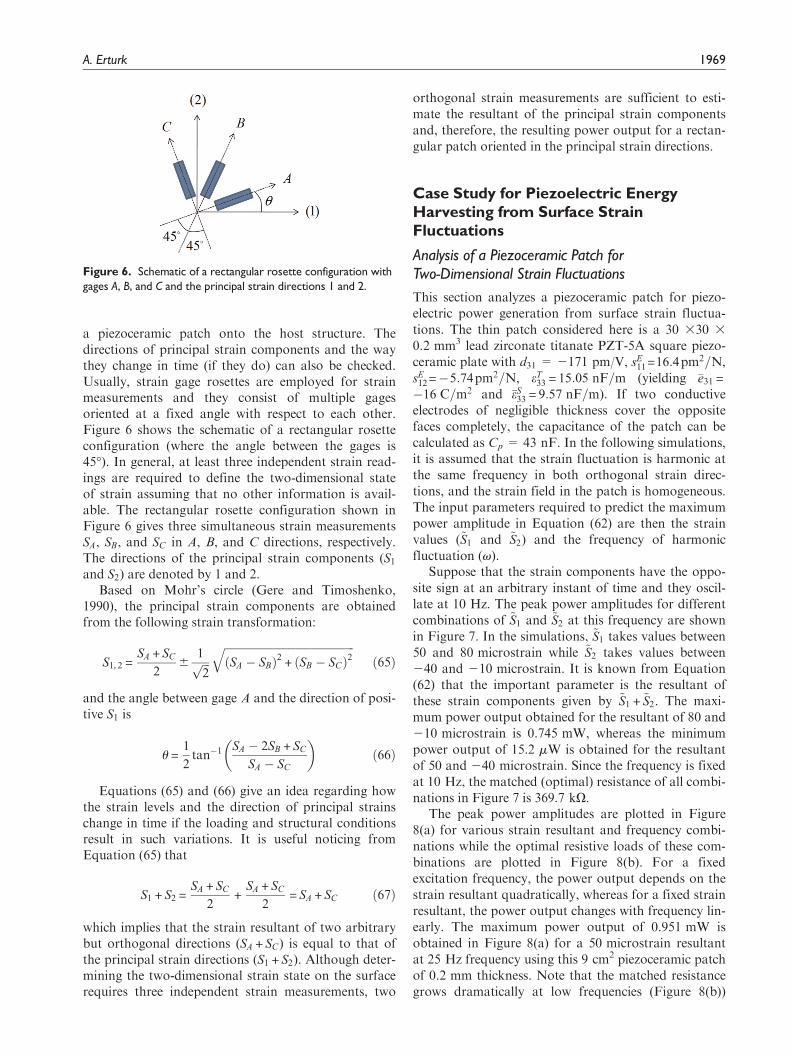
Suppose that the strain components have the oppo-site sign at an arbitrary instant of time and they oscil-late at 10 Hz. The peak power amplitudes for differentcombinations of ~S1 and ~S2 at this frequency are shownin Figure 7. In the simulations, ~S1 takes values between50 and 80 microstrain while ~S2 takes values between240 and 210 microstrain. It is known from Equation(62) that the important parameter is the resultant ofthese strain components given by ~S1 + ~S2. The maxi-mum power output obtained for the resultant of 80 and210 microstrain is 0.745 mW, whereas the minimumpower output of 15.2 mW is obtained for the resultantof 50 and 240 microstrain. Since the frequency is fixedat 10 Hz, the matched (optimal) resistance of all combi-nations in Figure 7 is 369.7 kO.
The peak power amplitudes are plotted in Figure8(a) for various strain resultant and frequency combi-nations while the optimal resistive loads of these com-binations are plotted in Figure 8(b). For a fixedexcitation frequency, the power output depends on thestrain resultant quadratically, whereas for a fixed strainresultant, the power output changes with frequency lin-early. The maximum power output of 0.951 mW isobtained in Figure 8(a) for a 50 microstrain resultantat 25 Hz frequency using this 9 cm2 piezoceramic patchof 0.2 mm thickness. Note that the matched resistancegrows dramatically at low frequencies (Figure 8(b))
Figure 6. Schematic of a rectangular rosette configuration withgages A, B, and C and the principal strain directions 1 and 2.
A. Erturk 1969
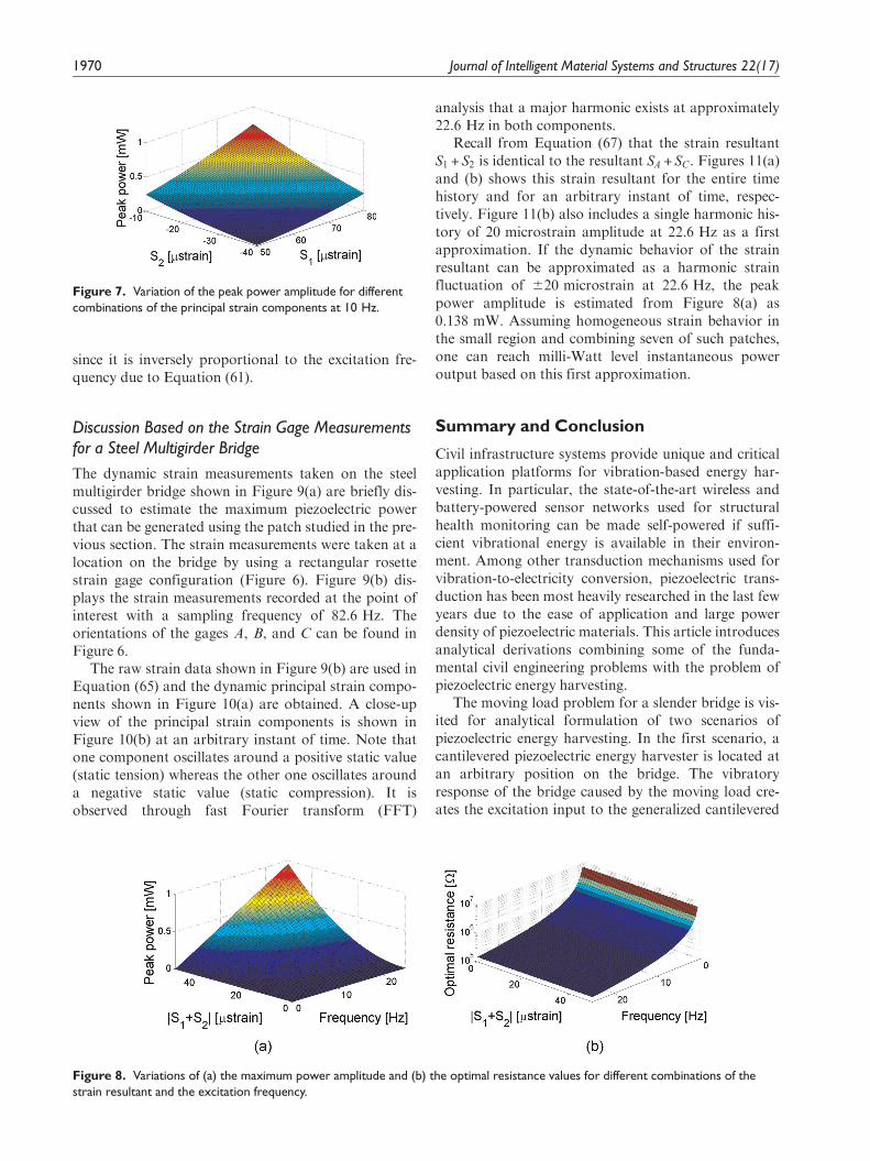
since it is inversely proportional to the excitation fre-quency due to Equation (61).
Discussion Based on the Strain Gage Measurementsfor a Steel Multigirder Bridge
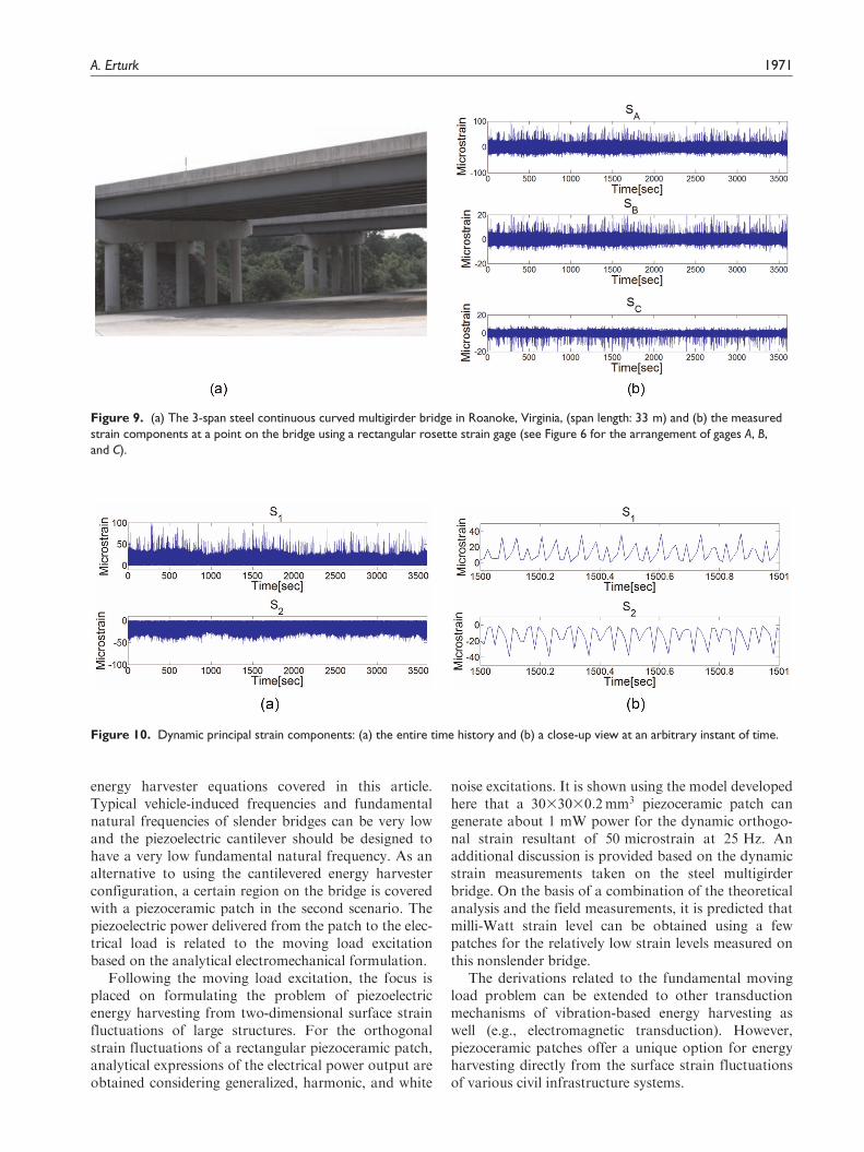
The dynamic strain measurements taken on the steelmultigirder bridge shown in Figure 9(a) are briefly dis-cussed to estimate the maximum piezoelectric powerthat can be generated using the patch studied in the pre-vious section. The strain measurements were taken at alocation on the bridge by using a rectangular rosettestrain gage configuration (Figure 6). Figure 9(b) dis-plays the strain measurements recorded at the point ofinterest with a sampling frequency of 82.6 Hz. Theorientations of the gages A, B, and C can be found inFigure 6.
The raw strain data shown in Figure 9(b) are used inEquation (65) and the dynamic principal strain compo-nents shown in Figure 10(a) are obtained. A close-upview of the principal strain components is shown inFigure 10(b) at an arbitrary instant of time. Note thatone component oscillates around a positive static value(static tension) whereas the other one oscillates arounda negative static value (static compression). It isobserved through fast Fourier transform (FFT)
analysis that a major harmonic exists at approximately22.6 Hz in both components.
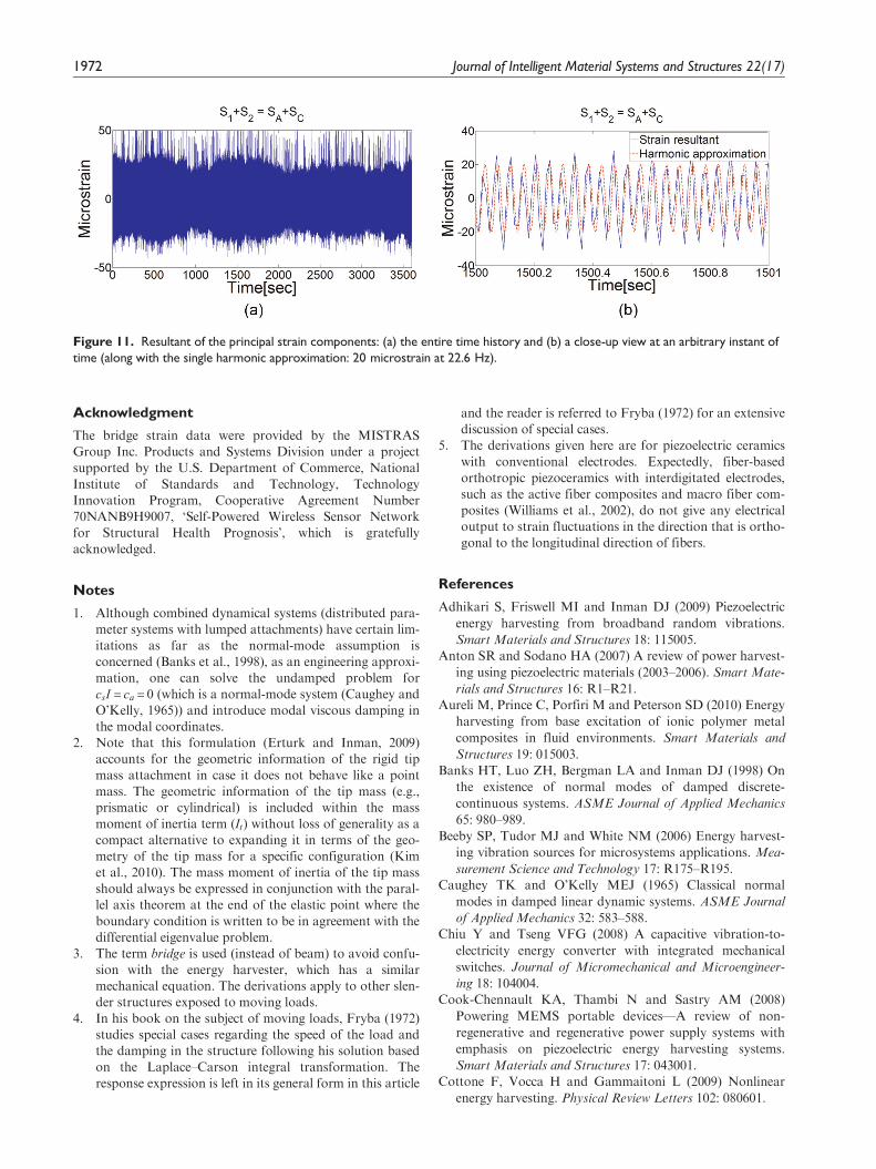
Recall from Equation (67) that the strain resultantS1 + S2 is identical to the resultant SA + SC. Figures 11(a)and (b) shows this strain resultant for the entire timehistory and for an arbitrary instant of time, respec-tively. Figure 11(b) also includes a single harmonic his-tory of 20 microstrain amplitude at 22.6 Hz as a firstapproximation. If the dynamic behavior of the strainresultant can be approximated as a harmonic strainfluctuation of 620 microstrain at 22.6 Hz, the peakpower amplitude is estimated from Figure 8(a) as0.138 mW. Assuming homogeneous strain behavior inthe small region and combining seven of such patches,one can reach milli-Watt level instantaneous poweroutput based on this first approximation.
Summary and Conclusion
Civil infrastructure systems provide unique and criticalapplication platforms for vibration-based energy har-vesting. In particular, the state-of-the-art wireless andbattery-powered sensor networks used for structuralhealth monitoring can be made self-powered if suffi-cient vibrational energy is available in their environ-ment. Among other transduction mechanisms used forvibration-to-electricity conversion, piezoelectric trans-duction has been most heavily researched in the last fewyears due to the ease of application and large powerdensity of piezoelectric materials. This article introducesanalytical derivations combining some of the funda-mental civil engineering problems with the problem ofpiezoelectric energy harvesting.
The moving load problem for a slender bridge is vis-ited for analytical formulation of two scenarios ofpiezoelectric energy harvesting. In the first scenario, acantilevered piezoelectric energy harvester is located atan arbitrary position on the bridge. The vibratoryresponse of the bridge caused by the moving load cre-ates the excitation input to the generalized cantilevered
Figure 7. Variation of the peak power amplitude for differentcombinations of the principal strain components at 10 Hz.
Figure 8. Variations of (a) the maximum power amplitude and (b) the optimal resistance values for different combinations of thestrain resultant and the excitation frequency.
1970 Journal of Intelligent Material Systems and Structures 22(17)
energy harvester equations covered in this article.Typical vehicle-induced frequencies and fundamentalnatural frequencies of slender bridges can be very lowand the piezoelectric cantilever should be designed tohave a very low fundamental natural frequency. As analternative to using the cantilevered energy harvesterconfiguration, a certain region on the bridge is coveredwith a piezoceramic patch in the second scenario. Thepiezoelectric power delivered from the patch to the elec-trical load is related to the moving load excitationbased on the analytical electromechanical formulation.
Following the moving load excitation, the focus isplaced on formulating the problem of piezoelectricenergy harvesting from two-dimensional surface strainfluctuations of large structures. For the orthogonalstrain fluctuations of a rectangular piezoceramic patch,analytical expressions of the electrical power output areobtained considering generalized, harmonic, and white
noise excitations. It is shown using the model developedhere that a 3033030:2mm3 piezoceramic patch cangenerate about 1 mW power for the dynamic orthogo-nal strain resultant of 50 microstrain at 25 Hz. Anadditional discussion is provided based on the dynamicstrain measurements taken on the steel multigirderbridge. On the basis of a combination of the theoreticalanalysis and the field measurements, it is predicted thatmilli-Watt strain level can be obtained using a fewpatches for the relatively low strain levels measured onthis nonslender bridge.
The derivations related to the fundamental movingload problem can be extended to other transductionmechanisms of vibration-based energy harvesting aswell (e.g., electromagnetic transduction). However,piezoceramic patches offer a unique option for energyharvesting directly from the surface strain fluctuationsof various civil infrastructure systems.
Figure 9. (a) The 3-span steel continuous curved multigirder bridge in Roanoke, Virginia, (span length: 33 m) and (b) the measuredstrain components at a point on the bridge using a rectangular rosette strain gage (see Figure 6 for the arrangement of gages A, B,and C).
Figure 10. Dynamic principal strain components: (a) the entire time history and (b) a close-up view at an arbitrary instant of time.
A. Erturk 1971
Acknowledgment
The bridge strain data were provided by the MISTRASGroup Inc. Products and Systems Division under a projectsupported by the U.S. Department of Commerce, National
Institute of Standards and Technology, TechnologyInnovation Program, Cooperative Agreement Number70NANB9H9007, ‘Self-Powered Wireless Sensor Networkfor Structural Health Prognosis’, which is gratefullyacknowledged.
Notes
1. Although combined dynamical systems (distributed para-meter systems with lumped attachments) have certain lim-itations as far as the normal-mode assumption isconcerned (Banks et al., 1998), as an engineering approxi-mation, one can solve the undamped problem forcsI = ca = 0 (which is a normal-mode system (Caughey andO’Kelly, 1965)) and introduce modal viscous damping inthe modal coordinates.
2. Note that this formulation (Erturk and Inman, 2009)accounts for the geometric information of the rigid tipmass attachment in case it does not behave like a pointmass. The geometric information of the tip mass (e.g.,prismatic or cylindrical) is included within the massmoment of inertia term (It) without loss of generality as acompact alternative to expanding it in terms of the geo-metry of the tip mass for a specific configuration (Kimet al., 2010). The mass moment of inertia of the tip massshould always be expressed in conjunction with the paral-lel axis theorem at the end of the elastic point where the
boundary condition is written to be in agreement with thedifferential eigenvalue problem.
3. The term bridge is used (instead of beam) to avoid confu-sion with the energy harvester, which has a similarmechanical equation. The derivations apply to other slen-der structures exposed to moving loads.
4. In his book on the subject of moving loads, Fryba (1972)studies special cases regarding the speed of the load andthe damping in the structure following his solution basedon the Laplace–Carson integral transformation. Theresponse expression is left in its general form in this article
and the reader is referred to Fryba (1972) for an extensivediscussion of special cases.
5. The derivations given here are for piezoelectric ceramics
with conventional electrodes. Expectedly, fiber-basedorthotropic piezoceramics with interdigitated electrodes,such as the active fiber composites and macro fiber com-posites (Williams et al., 2002), do not give any electricaloutput to strain fluctuations in the direction that is ortho-gonal to the longitudinal direction of fibers.
References
Adhikari S, Friswell MI and Inman DJ (2009) Piezoelectric
energy harvesting from broadband random vibrations.
Smart Materials and Structures 18: 115005.Anton SR and Sodano HA (2007) A review of power harvest-
ing using piezoelectric materials (2003–2006). Smart Mate-
rials and Structures 16: R1–R21.Aureli M, Prince C, Porfiri M and Peterson SD (2010) Energy
harvesting from base excitation of ionic polymer metal
composites in fluid environments. Smart Materials and
Structures 19: 015003.Banks HT, Luo ZH, Bergman LA and Inman DJ (1998) On
the existence of normal modes of damped discrete-
continuous systems. ASME Journal of Applied Mechanics
65: 980–989.Beeby SP, Tudor MJ and White NM (2006) Energy harvest-
ing vibration sources for microsystems applications. Mea-
surement Science and Technology 17: R175–R195.Caughey TK and O’Kelly MEJ (1965) Classical normal
modes in damped linear dynamic systems. ASME Journal
of Applied Mechanics 32: 583–588.Chiu Y and Tseng VFG (2008) A capacitive vibration-to-
electricity energy converter with integrated mechanical
switches. Journal of Micromechanical and Microengineer-
ing 18: 104004.Cook-Chennault KA, Thambi N and Sastry AM (2008)
Powering MEMS portable devices—A review of non-
regenerative and regenerative power supply systems with
emphasis on piezoelectric energy harvesting systems.
Smart Materials and Structures 17: 043001.Cottone F, Vocca H and Gammaitoni L (2009) Nonlinear
energy harvesting. Physical Review Letters 102: 080601.
Figure 11. Resultant of the principal strain components: (a) the entire time history and (b) a close-up view at an arbitrary instant oftime (along with the single harmonic approximation: 20 microstrain at 22.6 Hz).
1972 Journal of Intelligent Material Systems and Structures 22(17)

Daqaq MF (2010) Response of uni-modal duffing-type har-vesters to random forced excitations. Journal of Sound and
Vibration 329: 3621–3631.Elvin NG and Elvin AA (2009) A general equivalent circuit
model for piezoelectric generators. Journal of Intelligent
Material Systems and Structures 20: 3–9.Elvin NG, Elvin AA and Choi DH (2003) A self-powered
damage detection sensor. The Journal of Strain Analysis
for Engineering Design 38: 115–124.Elvin NG, Lajnef N and Elvin AA (2006) Feasibility of struc-
tural monitoring with vibration powered sensors. Smart
Materials and Structures 15: 977–986.Erturk A, Hoffmann J and Inman DJ (2009a) A piezomagne-
toelastic structure for broadband vibration energy harvest-ing. Applied Physics Letters 94: 254102.
Erturk A and Inman DJ (2009) An experimentally validatedbimorph cantilever model for piezoelectric energy harvest-
ing from base excitations. Smart Materials and Structures
18: 025009.Erturk A and Inman DJ (2011a) Broadband piezoelectric
power generator on high-energy orbits of the bistable duff-ing oscillator with electromechanical coupling. Journal ofSound and Vibration 330: 2339–2353.
Erturk A and Inman DJ (2011b) Parameter identification andoptimization in piezoelectric energy harvesting: Analyticalrelations, asymptotic analyses, and experimental valida-tions. IMechE Journal of Systems and Control Engineering
225: 485–496.Erturk A, Tarazaga P, Farmer JR and Inman DJ (2009b)
Effect of strain nodes and electrode configuration onpiezoelectric energy harvesting from cantilevered beams.ASME Journal of Vibration and Acoustics 131: 011010.
Fryba L (1972) Vibration of Solids and Structures under Mov-
ing Loads. Groningen, the Netherlands: Noordhoff Inter-national Publishing.
Gere JM and Timoshenko SP (1990) Mechanics of Materials.Boston, MA: PWS-Kent Publishing Co.
Halvorsen E (2008) Energy harvesters driven by broadbandrandom vibrations. Journal of Microelectromechanical Sys-
tems 17: 1061–1071.Kim M, Hoegen M, Dugundji J and Wardle BL (2010) Mod-
eling and experimental verification of proof mass effectson vibration energy harvester performance. Smart Materi-
als and Structures 19: 045023.Lesieutre GA, Ottman GK and Hofmann HF (2004) Damp-
ing as a result of piezoelectric energy harvesting. Journal ofSound and Vibration 269: 991–1001.
Litak G, Friswell MI and Adhikari S (2010) Magnetopiezoe-lastic energy harvesting driven by random excitations.Applied Physics Letters 96: 214103.
Mann BP and Sims ND (2009) Energy harvesting from the
nonlinear oscillations of magnetic levitation. Journal of
Sound and Vibration 319: 515–530.Meirovitch L (2001) Fundamentals of Vibrations. New York:
McGraw-Hill.Newland DE (1993) Random Vibrations, Spectral and Wavelet
Analysis. New York: John Wiley & Sons.Olsson M (1991) On the fundamental moving load problem.
Journal of Sound and Vibration 145: 299–307.Ozevin D, Greve DW, Oppenheim IJ and Pessiki SP (2006)
Resonant capacitive MEMS acoustic emission transducers.
Smart Materials and Structures 15: 1863–1871.Rao SS (2007) Vibration of Continuous Systems. Hoboken,
NJ: John Wiley & Sons.Renno JM, Daqaq MF and Inman DJ (2009) On the optimal
energy harvesting from a vibration source. Journal of
Sound and Vibration 320: 386–405.Scruggs JT (2009) An optimal stochastic control theory for
distributed energy harvesting networks. Journal of Sound
and Vibration 320: 707–725.
Shigeishi M, Colombo S, Broughton KJ, Rutledge H, Batchelor
AJ and Forde MC (2001) Acoustic emission to assess and
monitor the integrity of bridges. Construction and Building
Materials 15: 35–49.Shu YC, Lien IC and Wu WJ (2007) An improved analysis of
the SSHI interface in piezoelectric energy harvesting.
Smart Materials and Structures 16: 2253–2264.Sodano H, Park G and Inman DJ (2004) A review of power
harvesting from vibration using piezoelectric materials.
Shock and Vibration Digest 36: 197–205.Stanton SC, Erturk A, Mann BP and Inman DJ (2010a)
Resonant manifestation of intrinsic nonlinearity within
electroelastic micropower generators. Applied Physics Let-
ters 97: 254101.Stanton SC, McGehee CC and Mann BP (2009) Reversible
hysteresis for broadband magnetopiezoelastic energy har-
vesting. Applied Physics Letters 96: 174103.Stanton SC, McGehee CC and Mann BP (2010b) Nonlinear
dynamics for broadband energy harvesting: Investigation
of a bistable inertial generator. Physica D 239: 640–653.Timoshenko SP, Young DH and Weaver W (1974) Vibration
Problems in Engineering. New York: John Wiley & Sons.Wang L and Yuan FG (2008) Vibration energy harvesting by
magnetostrictive material. Smart Materials and Structures
17: 045009.Williams RB, Park G, Inman DJ and Wilkie WK (2002) An
overview of composite actuators with piezoceramic fibers.
Proceedings of the 20th International Modal Analysis Con-
ference 4753: 421–427.
A. Erturk 1973