Embed Size (px)
Citation preview
DOE/METC/C-96/720 1
Pressure-Gain Combustion for Gas Turbines
Authors: R. Gemmen G. Richards M. Janus
Conference Title: Advanced Coal-Fired Power Systems '95 Review Meeting
Conference Location: Morgantown, West Virginia
Conference Dates: June 27-29, 1995
Conference Sponsor: U.S. Department of Energy, Morgantown Energy Technology Center
DISCLAIMER
This report was prepared as an account of work sponsored by an agency of the United States Government. Neither the United States Government nor any agency thereof, nor any of their employees, makes any warranty, express or implied, or assumes any legal liability or responsibility for the accuracy, completeness, or usefulness of any information, apparatus, product, or process disclosed, or represents that its use would not infringe privately owned rights. Reference herein to any specific commercial product, process, or service by trade name, trademark, manufacturer, or otherwise does not necessarily constitute or imply its endorsement, recommendation, or favoring by the United States Government or any agency thereof. The views and opinions of authors expressed herein do not necessarily state or reflect those of the United States Government or any agency thereof.
This report has been reproduced directly from the best available copy.
Available to DOE mcl DOE contractors from the Office of Scientific and Technical Information, 175 Oak Ridge Turnpike, Oak Ridge, TN 37831; prices available at (615) 576-8401.
Available to the public from the National Technical Information Service, US. Department of Commerce, 5285 Port Royal Road, Springfield, VA 22161; phone orders accepted at (703) 487-4650.
PAS Pressure-Gain Combustion for Gas Turbines
Randall S. Gemmen George A. Richards Michael C . Janus
Morgantown Energy Technology Center
ABSTRACT
As part of the Department of Energy's Advanced Gus Turbine Systems Program, an investigation has been performed to evaluate "pressure-gain" combustion systems for gas turbine applications. Results from the investigation have shown that, due to the oscillatory combustion process, a pressure boost can be achieved for suitable combustor geometries. The pressure gains achieved thus far have been as high as 1 percent. It has also been shown that for some combustor designs operating under typical gas turbine conditions, NO, and CO emissions are about 30 ppmv and 8 ppmv, respectively. It is believed that with optimized designs, further improvements in both pressure gain and emissions may be pos- sible. We have concluded that this technology remains a candidate for improving the effi- ciency of a gas turbine while reducing pollut- ant emissions.
OBJECTIVES
This research supports the Department of Energy's Advanced Gas Turbine Systems Pro- gram. The goal of this program is to increase cycle efficiencies and to reduce pollutant emissions of utility and industrial gas turbine power generating systems. The objectives of the work reported here are to (1) determine how pressure gain can be achieved in combus- tion systems; (2) determine pressure effects for pressure-gain systems; and (3) evaluate their pollutant performance. Since such pressure- gain systems necessarily impose unsteadiness
to the gas flow through a gas turbine, the ability to minimize such unsteadiness outside the combustor is also assessed.
BACKGROUND
Several investigators have studied combus- tion systems capable of producing pressure gain: Thring (1961), Porter (1958), and Kentfield (1988), to name a few. Designs have varied from piston-cylinder arrangements to those supporting a fluid mechanic reso- nance. In all cases, the fundamental feature that enables pressure gain to be achieved is the ability to burn fuel in a constant-volume man- ner. The closer a system imitates a constant- volume combustion process, the greater will be the achieved pressure gain during the combus- tion event. Hence, piston-cylinder combustion geometries can usually be expected to produce a greater pressure gain given their more constant volume combustion process, as com- pared to acoustic devices that experience greater volumetric expansion.
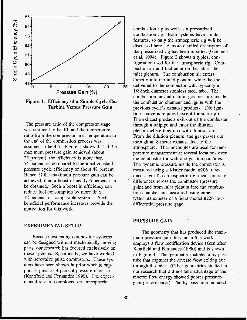
Figure 1 shows how the efficiency of a simple-cycle gas turbine can be increased with pressure gain. For a detailed theoretical analysis, see Gemmen et al. (1992). Here, the pressure gain is shown as percent increase from compressor exit stagnation pressure to turbine inlet stagnation pressure: (P,-P,)/ Pc*lOO, where P, is the compressor exit pres- sure, and P, is the turbine inlet pressure. The figure is based on an analysis assuming thermodynamically ideal conditions for all components and a specific heat ratio of 1.4.
-79-
combustion rig as well as a pressurized 54 - 53 - combustion rig. Both systems have similar
features, so only the atmospheric rig will be 52 - discussed here. A more detailed description of
the pressurized rig has been reported (Gemmen et al. 1994). Figure 2 shows a typical con- figuration used for the atmospheric rig. Com- bustion air and fuel enter on the left at the
51 - 50 - 49 - inlet plenum. The combustion air enters
4 directly into the inlet plenum, while the fuel is
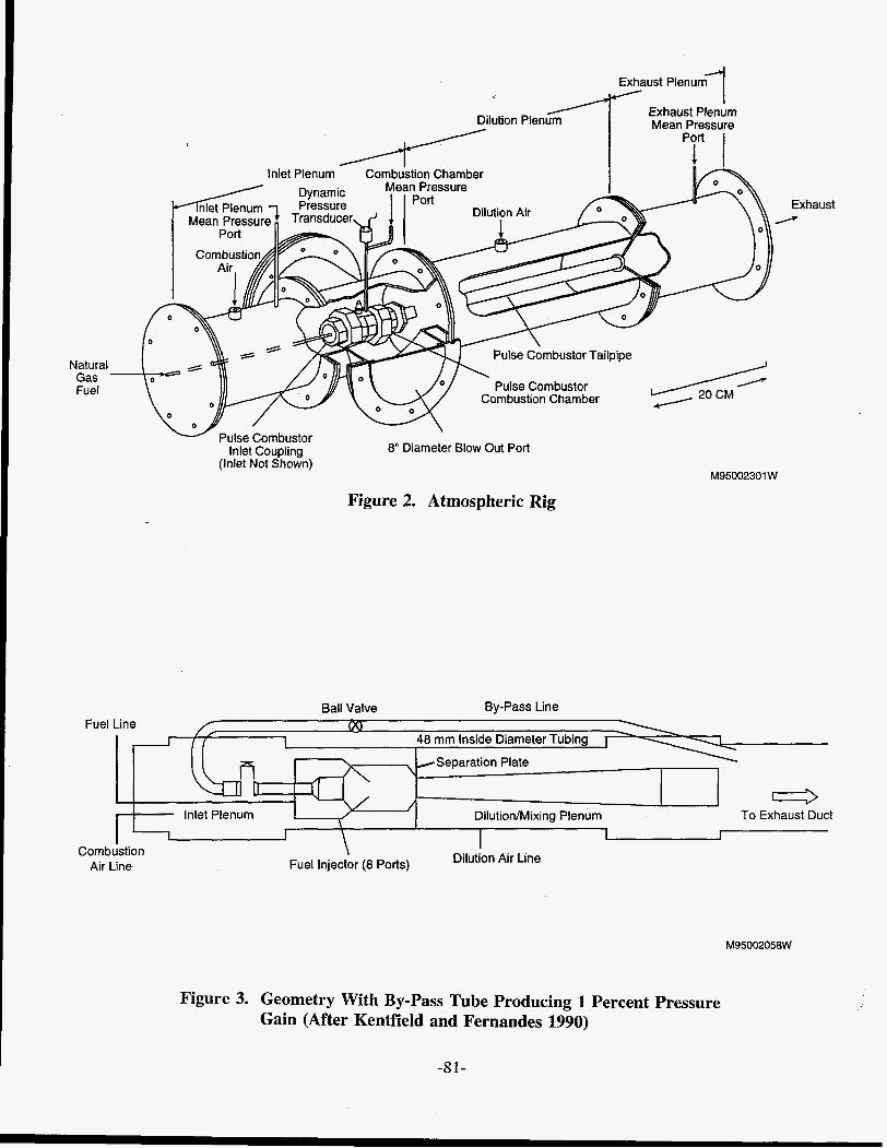
d5 delivered to the combustor with typically a 1/8-inch diameter stainless steel tube. The combustion air and natural gas fuel mix inside the combustion chamber and ignite with the previous cycle’s exhaust products. (No igni- tion source is required except for start-up.) The exhaust products exit out of the combustor through a tailpipe and enter the dilution plenum where they mix with dilution air. From the dilution plenum, the gas passes out through an 8-meter exhaust duct to the atmosphere. Thermocouples are used for tem- perature measurement at several locations over the combustor for wall and gas temperatures. The dynamic pressure inside the combustor is measured using a Kistler model #206 trans- ducer. For the atmospheric rig, mean pressure differences across the combustor (pressure gain) and from inlet plenum into the combus- tion chamber are measured using either a water manometer or a Setra model #226 low- differential pressure gage.
48 0 5 10 15 20
Pressure Gain (%)
Figure 1. Efficiency of a Simple-Cycle Gas Turbine Versus Pressure Gain
The pressure ratio of the compressor stage was assumed to be 10, and the temperature ratio from the compressor inlet temperature to the end of the combustion process was assumed to be 4.5. Figure 1 shows that at the maximum pressure gain achieved (about 25 percent), the efficiency is more than 54 percent as compared to the ideal constant pressure cycle efficiency of about 48 percent. Hence, if the maximum pressure gain can be achieved, then a boost of nearly 6 percent can be obtained.’ Such a boost in efficiency can reduce fuel consumption by more than 12 percent for comparable systems. Such beneficial performance increases provide the motivation for this work.
PRESSURE GAIN EXPERIMENTAL SETUP
Because resonating combustion systems can be designed without mechanically moving parts, our research has focused exclusively on these systems. Specifically, we have worked with aerovalve pulse combustors. These sys- tems have been shown in prior work to sup- port as great as 4 percent pressure increase (Kentfield and Fernandes 1990). The experi- mental research employed an atmospheric
The geometry that has produced the maxi- mum pressure gain thus far in this work employs a flow rectification device taken after Kentfield and Fernandes (1990) and is shown in Figure 3. This geometry includes a by-pass tube that captures the reverse flow exiting out through the inlet. (Other geometries studied in our research that did not take advantage of the reverse flow energy showed poorer pressure- gain performance.) The by-pass tube included
-80-
Inlet Plenum Combustion Chamber
Exhaust /
Natural Gas Fuel Pulse Combustor
Combustion Chamber
Inlet Coupling (Inlet Not Shown)
8" Diameter Blow Out Port
M95002301 W
Figure 2. Atmospheric Rig
Ball Valve By-Pass Line Fuel Line
,Separation Plate
e Dilutionhlixing Plenum To Exhaust Duct
Combustion Air Line
M95002058W
Figure 3. Geometry With By-Pass Tube Producing 1 Percent Pressure Gain (After Kentfield and Fernandes 1990)
-81-
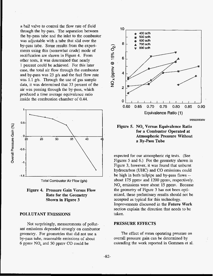
a ball valve to control the flow rate of fluid through the by-pass. The separation between the by-pass tube and the inlet to the combustor was adjustable with a tube that slid over the by-pass tube. Some results from the experi- ments using this (somewhat crude) mode of rectification are shown in Figure 4. From other tests, it was determined that nearly 1 percent could be achieved. For this later case, the total air flow through the combustor and by-pass was 23 g/s and the fuel flow rate was 1.1 g/s . Through the use of gas sample data, it was determined that 33 percent of the air was passing through the by-pass, which produced a time average equivalence ratio inside the combustion chamber of 0.44.
1
. C a 8 . o F io 25 30
3 -0.5-
a Q)
.-
3 v) v)
- - L
6 -1..
Total Combustor Air Flow (g/s)
Figure 4. Pressure Gain Versus Flow Rate for the Geometry Shown in Figure 3
POLLUTANT EMISSIONS
Not surprisingly, measurements of pollut- ant emissions depended strongly on combustor geometry. For geometries that did not use a by-pass tube, reasonable emissions of about 6 ppmv NO, and 50 ppmv CO could be
e 400scfh
600 scfh - A 700scfh
9g 800 scfh
- 500scfh
I I I I I I I I I I I
0.60 0.65 0.70 0.75 0.80 0.85 0.90
Equivalence Ratio (1)
M95000908W
Figure 5. NO, Versus Equivalence Ratio for a Combustor Operated at Atmospheric Pressure Without a By-Pass Tube
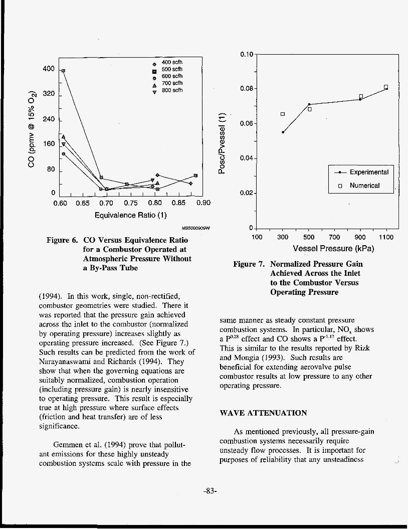
expected for our atmospheric rig tests. (See Figures 5 and 6.) For the geometry shown in Figure 3, however, it was found that unburnt hydrocarbon (UHC) and CO emissions could be high in both tailpipe and by-pass flows -- about 175 ppmv and 1200 ppmv, respectively. NO, emissions were about 15 ppmv. Because the geometry of Figure 3 has not been opti- mized, these preliminary results should not be accepted as typical for this technology. Improvements discussed in the Future Work section explain the direction that needs to be taken.
PRESSURE EFFECTS
The effect of mean operating pressure on overall pressure gain can be determined by extending the work reported in Gemmen et al.
-82-
400
3 320 0
- 240 8
& 160
0
$!
>
Q W
80
0
e 400 scfh 500scfh
A 700 scfh e 600xfh
800 scfh
1 1 1 1 1 1 1 1 1 1 1
0.60 0.65 0.70 0.75 0.80 0.85 0.90
Equivalence Ratio (1)
M95000909W
Figure 6. CO Versus Equivalence Ratio for a Combustor Operated at Atmospheric Pressure Without a By-Pass Tube
(1994). In this work, single, non-rectified, combustor geometries were studied. There it was reported that the pressure gain achieved across the inlet to the combustor (normalized by operating pressure) increases slightly as operating pressure increased. (See Figure 7.) Such results can be predicted from the work of Narayanaswami and Richards (1994). They show that when the governing equations are suitably normalized, combustion operation (including pressure gain) is nearly insensitive to operating pressure. This result is especially true at high pressure where surface effects (friction and heat transfer) are of less significance.
Gemmen et al. (1994) prove that pollut- ant emissions for these highly unsteady combustion systems scale with pressure in the
0*1°*
0.08 -
- n .
- 0.06- a, v) 0 a,
O 0.04- v) 0
7 W
- h \
a - - Experimental
0 Numerical ,
0.02 -
-
0 I I I I I I I I I I
100 300 500 700 900 1100
Vessel Pressure (kPa)
Figure 7. Normalized Pressure Gain Achieved Across the Inlet to the Combustor Versus Operating Pressure
same manner as steady constant pressure combustion systems. In particular, NO, shows a Po2* effect and CO shows a P-l.I7 effect. This is similar to the results reported by Rizk and Mongia (1993). Such results are beneficial for extending aerovalve pulse combustor results at low pressure to any other operating pressure.
WAVE ATTENUATION
As mentioned previously, all pressure-gain combustion systems necessarily require unsteady flow processes. It is important for purposes of reliability that any unsteadiness
-83-
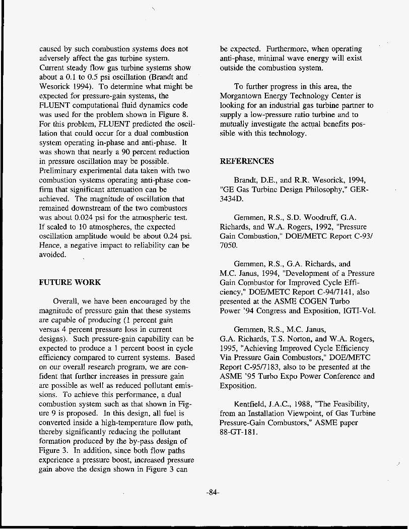
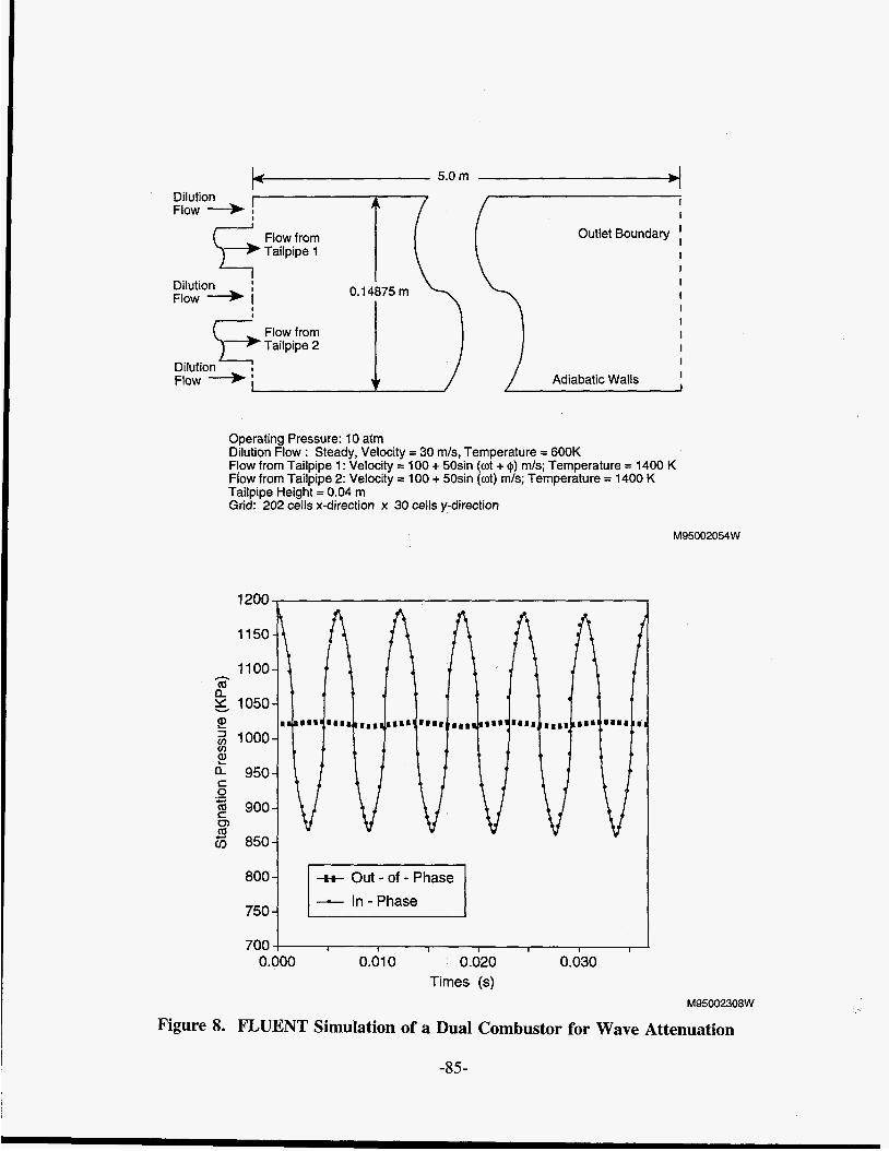
caused by such combustion systems does not adversely affect the gas turbine system. Current steady flow gas turbine systems show about a 0.1 to 0.5 psi oscillation (Brandt and Wesorick 1994). To determine what might be expected for pressure-gain systems, the FLUENT computational fluid dynamics code was used for the problem shown in Figure 8. For this problem, FLUENT predicted the oscil- lation that could occur for a dual combustion system operating in-phase and anti-phase. It was shown that nearly a 90 percent reduction in pressure oscillation may be possible. Preliminary experimental data taken with two combustion systems operating anti-phase con- firm that significant attenuation can be achieved. The magnitude of oscillation that remained downstream of the two combustors was about 0.024 psi for the atmospheric test. If scaled to 10 atmospheres, the expected oscillation amplitude would be about 0.24 psi. Hence, a negative impact to reliability can be avoided.
FUTURE WORK
Overall, we have been encouraged by the magnitude of pressure gain that these systems are capable of producing (1 percent gain versus 4 percent pressure loss in current designs). Such pressure-gain capability can be expected to produce a 1 percent boost in cycle efficiency compared to current systems. Based on our overall research program, we are con- fident that further increases in pressure gain are possible as well as reduced pollutant emis- sions. To achieve this performance, a dual combustion system such as that shown in Fig- ure 9 is proposed. In this design, all fuel is converted inside a high-temperature flow path, thereby significantly reducing the pollutant formation produced by the by-pass design of Figure 3. In addition, since both flow paths experience a pressure boost, increased pressure gain above the design shown in Figure 3 can
be expected. Furthermore, when operating anti-phase, minimal wave energy will exist outside the combustion system.
To further progress in this area, the Morgantown Energy Technology Center is looking for an industrial gas turbine partner to supply a low-pressure ratio turbine and to mutually investigate the actual benefits pos- sible with this technology.
REFERENCES
Brandt, D.E., and R.R. Wesorick, 1994, "GE Gas Turbine Design Philosophy," GER- 3434D.
Gemmen, R.S., S.D. Woodruff, G.A. Richards, and W.A. Rogers, 1992, "Pressure Gain Combustion," DOEMETC Report C-93/ 7050.
Gemmen, R.S., G.A. Richards, and M.C. Janus, 1994, "Development of a Pressure Gain Combustor for Improved Cycle Effi- ciency," DOEMETC Report C-94/7 141, also presented at the ASME COGEN Turbo Power '94 Congress and Exposition, IGTI-Vol.
Gemmen, R.S., M.C. Janus, G.A. Richards, T.S. Norton, and W.A. Rogers, 1995, "Achieving Improved Cycle Efficiency Via Pressure Gain Combustors," DOEMETC Report C-95/7183, also to be presented at the ASME '95 Turbo Expo Power Conference and Exposition.
Kentfield, J.A.C., 1988, "The Feasibility, from an Installation Viewpoint, of Gas Turbine Pressure-Gain Combustors," ASME paper 88-GT- 181.
-84-
Flow from Outlet Boundary Tailpipe 1
I I I I I I
I
I
Dilution FIOW + i
Flow from
Dilution Flow 4 1 1 ,/ Adiabatic Walls j
Operating Pressure: 10 atm Dilution Flow : Steady, Velocity = 30 m/s, Temperature = 600K Flow from Tailpipe 1: Velocity = 100 + 50sin (wt + I$) m/s; Temperature = 1400 K Flow from Tailpipe 2: Velocity = 100 + 50sin (at) m/s; Temperature = 1400 K . . Tailpipe Height = 0.04 m Grid: 202 cells x-direction x 30 cells y-direction
1200 ,
-H- Out - of - Phase - In-Phase 750 8ooj E , , , ,
700 0.000 0.01 0 0.020 0.030
Times (s)
M95002054W
M95002308W
Figure 8. FLUENT Simulation of a Dual Combustor for Wave Attenuation
-85-
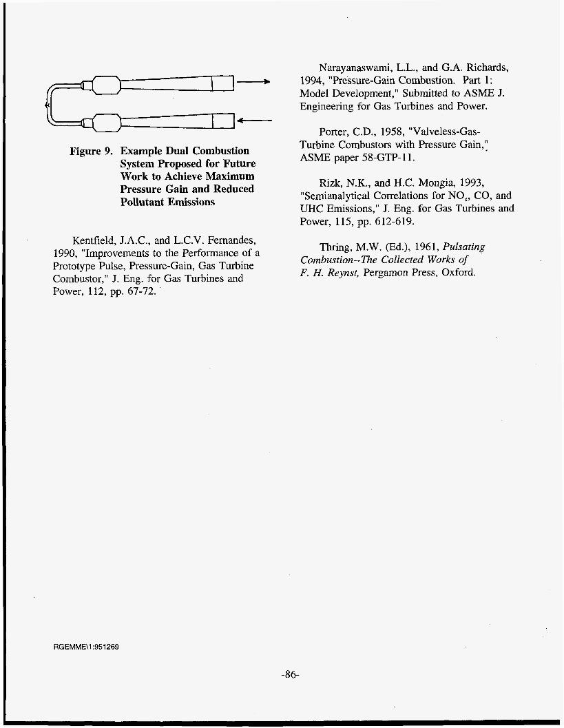
Figure 9. Example Dual Combustion System Proposed for Future Work to Achieve Maximum Pressure Gain and Reduced Pollutant Emissions
Kentfield, J.A.C., and L.C.V. Fernandes, 1990, "Improvements to the Performance of a Prototype Pulse, Pressure-Gain, Gas Turbine Combustor," J. Eng. for Gas Turbines and Power, 112, pp. 67-72.
Narayanaswami, L.L., and G.A. Richards, 1994, "Pressure-Gain Combustion. Part I: Model Development," Submitted to ASME J. Engineering for Gas Turbines and Power.
Porter, C.D., 1958, "Valveless-Gas- Turbine Combustors with Pressure Gain," ASME paper 58-GTP- 1 1.
Rizk, N.K., and H.C. Mongia, 1993, "Semianalytical Correlations for NO,, CO, and UHC Emissions," J. Eng. for Gas Turbines and Power, 115, pp. 612-619.
Thring, M.W. (Ed.), 1961, Pulsating Combustion--The Collected Works of F. H. Reynst, Pergamon Press, Oxford.
RGEMME\1:951269
-86-