Embed Size (px)
Citation preview
DOE Fundamentals
ELECTRICAL SCIENCE
Module 15
Electrical Distribution Systems
Electrical Science Electrical Distribution Systems
i
TABLE OF CONTENTS
Table of Co nte nts TABLE OF CONTENTS ................................................................................................... i
LIST OF FIGURES .......................................................................................................... iii
LIST OF TABLES ............................................................................................................iv
REFERENCES ................................................................................................................ v
OBJECTIVES ..................................................................................................................vi
SYSTEM COMPONENTS AND PROTECTION DEVICES ............................................. 1
Single (One-Line) Diagram .......................................................................................... 1
Commercial or Utility Power ........................................................................................ 1
Diesel Power................................................................................................................ 1
Failure-Free Power ...................................................................................................... 3
Neutral Grounding ....................................................................................................... 3
Voltage Class............................................................................................................... 3
Protective Relays ......................................................................................................... 3
Overlapping Protective Zones...................................................................................... 4
Fuses ........................................................................................................................... 5
Summary ..................................................................................................................... 6
CIRCUIT BREAKERS ..................................................................................................... 7
Introduction .................................................................................................................. 7
Low-Voltage Air Circuit Breakers ................................................................................ 7
High-Voltage Circuit Breakers.................................................................................... 11
Circuit Breaker Control .............................................................................................. 11
Summary ................................................................................................................... 14
MOTOR CONTROLLERS ............................................................................................. 15
Motor Controllers ....................................................................................................... 15
Manual Controllers ..................................................................................................... 15
Magnetic Controller .................................................................................................... 16
Motor Controller Types and Operation ....................................................................... 18
Summary ................................................................................................................... 20
WIRING SCHEMES AND GROUNDING ...................................................................... 21
Electrical Science Electrical Distribution Systems
ii
Introduction ................................................................................................................ 21
Terminology ............................................................................................................... 22
Single-Phase Power .................................................................................................. 22
Three-Phase Wiring Schemes ................................................................................... 24
3-Wire, Three-Phase Delta System ........................................................................... 24
4-Wire, Three-Phase Delta System ........................................................................... 25
4-Wire, Three-Phase Wye System ............................................................................ 26
Summary ................................................................................................................... 27
Electrical Science Electrical Distribution Systems
iii
LIST OF FIGURES
Figure 1 One-Line Distribution Diagram ................................................................. 2
Figure 2 Protective Relaying Zones ....................................................................... 4
Figure 3 Types of Fuses ........................................................................................ 5
Figure 4 Molded Case Circuit Breaker ................................................................... 7
Figure 5 Cutaway View of Molded Case Circuit Breaker ....................................... 8
Figure 6 Large Air Circuit Breaker ........................................................................ 10
Figure 7 Simple Circuit Breaker Control Circuit - Breaker Open .......................... 12
Figure 8 Simple Circuit Breaker Control Circuit - Breaker Closed ........................ 13
Figure 9 Single Phase Manual Controller ............................................................ 16
Figure 10 Magnetic Contactor Assembly ............................................................... 17
Figure 11 Typical Three-Phase Magnetic Controller .............................................. 18
Figure 12 LVP Controller ....................................................................................... 18
Figure 13 LVR Controller ....................................................................................... 19
Figure 14 LURE Controller ..................................................................................... 19
Figure 15 Three-Phase to Single-Phase Connections ........................................... 23
Figure 16 3-Wire Edison Scheme ........................................................................... 24
Figure 17 3-Wire, Three-Phase Delta Scheme ...................................................... 25
Figure 18 4-Wire Delta System .............................................................................. 26
Figure 19 4-Wire, Three Phase Wye System ......................................................... 27

Electrical Science Electrical Distribution Systems
iv
LIST OF TABLES
NONE
Electrical Science Electrical Distribution Systems
v
REFERENCES
Gussow, Milton, Schaum's Outline of Basic Electricity, 2nd Edition, McGraw-Hill.
Academic Program for Nuclear Power Plant Personnel, Volume II, Columbia,
MD: General Physics Corporation, Library of Congress Card #A 326517, 1982.
Nasar and Unnewehr, Electromechanics and Electric Machines, 2nd Edition, John
Wiley and Sons.
Nooger and Neville Inc., Van Valkenburgh, Basic Electricity, Vol. 5, Hayden Book
Company.
Lister, Eugene C., Electric Circuits and Machines, 5th Edition, McGraw-Hill.
Croft, Hartwell, and Summers, American Electricians’ Handbook, 16th Edition,
McGraw-Hill.
Mason, C. Russell, The Art and Science of Protective Relaying, John Wiley and
Sons.
Mileaf, Harry, Electricity One - Seven, Revised 2nd Edition, Prentice Hall.
Kidwell, Walter, Electrical Instruments and Measurements, McGraw-Hill.
NFPA 70, National Electrical Code (2011 Edition), National Fire Protection
Association.
Electrical Science Electrical Distribution Systems
vi
OBJECTIVES
TERMINAL OBJECTIVE
1.0 Given the functional characteristics of an AC power source and the intended
load, DESCRIBE the necessary components and the wiring scheme to provide a
safe Electrical Distribution System.
ENABLING OBJECTIVES
1.1 EXPLAIN the following terms as they apply to Electrical Distribution Systems:
a. Single (one-line) diagram
b. Commercial or utility power
c. Diesel power
d. Failure-free power
e. Neutral grounding
f. Voltage class
g. Protective relays
h. Overlapping protective zones
1.2 DESCRIBE the protection provided by each of the following:
a. Fuses
b. Protective relays
1.3 STATE the purpose of circuit breakers.
1.4 Given a simple schematic of a circuit breaker control circuit, DESCRIBE the
operation of that breaker during remote operation and automatic tripping.
1.5 LIST the three most widely-used protective features that may be incorporated
into a circuit breaker control circuit.
1.6 STATE the function of motor controllers.
1.7 STATE three protective features (overloads) that may be incorporated into a
motor controller.
1.8 Given a simplified drawing of a motor controller, DESCRIBE the operation of that
motor controller.
Electrical Science Electrical Distribution Systems
vii
1.9 DEFINE the following terms as they apply to wiring schemes used in power
distribution systems:
a. Ampacity
b. Bond
c. Conductor
d. Ground
e. Ground voltage
f. Leg
g. Neutral
h. Phase voltage
1.10 DESCRIBE the two methods of connecting single-phase loads to a three-phase
power source.
1.11 DESCRIBE the purpose of the following power distribution schemes.
a. 3-wire, single-phase Edison system
b. 3-wire, three-phase Delta system
c. 4-wire, three-phase Delta system
d. 4-wire, three-phase Wye system
Electrical Science System Components & Electrical Distribution Systems Protection Devices
1
SYSTEM COMPONENTS AND PROTECTION DEVICES
Nuclear facilities rely on dependable electrical distribution systems to
provide power to key vital equipment. Knowledge of the basic electrical
power distribution system and its components will help the operator
understand the importance of electrical power distribution systems.
EO 1.1 EXPLAIN the following terms as they apply to Electrical Distribution
Systems:
a. Single (one-line) diagram
b. Commercial or utility power
c. Diesel power
d. Failure-free power
e. Neutral grounding
f. Voltage class
g. Protective relays
h. Overlapping protective zones
EO 1.2 DESCRIBE the protection provided by each of the following:
a. Fuses
b. Protective relays
Single (One-Line) Diagram
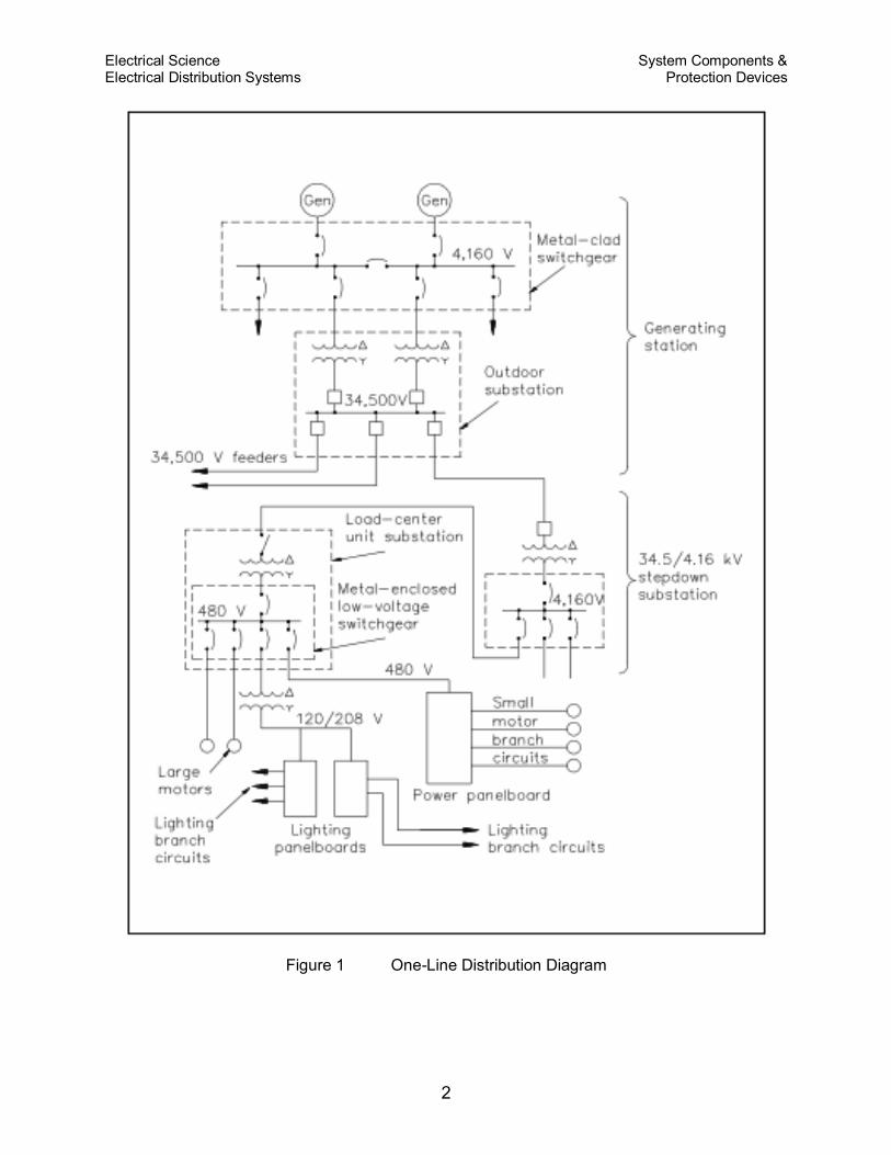
A single or one-line diagram of a distribution system is a simple and easy-to-read
diagram showing power supplies, loads, and major components in the distribution
system (Figure 1).
Commercial or Utility Power
Commercial or utility power is electrical power that is provided by commercial
generating systems to the facility.
Diesel Power
Diesel power is power generated by a diesel-driven generator. Diesel-driven generators
are the most economical and practical source of "standby power."
Electrical Science System Components & Electrical Distribution Systems Protection Devices
2
Figure 1 One-Line Distribution Diagram
Electrical Science System Components & Electrical Distribution Systems Protection Devices
3
Failure-Free Power
Failure-free power is accomplished by providing vital equipment with automatic
switching between two or more power supplies so that interruption of power is
minimized.
Neutral Grounding
Neutral grounding in electrical distribution systems helps prevent accidents to personnel
and damage to property caused by: fire in case of lightning; a breakdown between
primary and secondary windings of transformers; or accidental contact of high-voltage
wires and low- voltage wires. If some point on the circuit is grounded (in this case
neutral ground), lightning striking the wires will be conducted into the ground, and
breakdown between the primary and secondary windings of a transformer will cause the
primary transformer fuses to blow. Another advantage of neutral grounding is that it
reduces the amount of insulation required for high-voltage transmission lines.
Voltage Class
Voltage in distribution systems is classified into three groups: high voltage, intermediate
voltage, and low voltage. High voltage is voltage that is above 15,000 volts,
intermediate voltage is voltage between 15,000 volts and 600 volts, and low voltage is
voltage at 600 volts or less.
Protective Relays
Protective relays are designed to cause the prompt removal of any part of a power
system that might cause damage or interfere with the effective and continuous
operation of the rest of the system. Protective relays are aided in this task by circuit
breakers that are capable of disconnecting faulty components or subsystems.
Protective relays can be used for types of protection other than short circuit or
overcurrent. The relays can be designed to protect generating equipment and electrical
circuits from any undesirable condition, such as undervoltage, underfrequency, or
interlocking system lineups.
There are only two operating principles for protective relays: (1) electromagnetic
attraction and (2) electromagnetic induction. Electromagnetic attraction relays operate
by a plunger being drawn up into a solenoid or an armature that is attracted to the poles
of an electromagnet. This type of relay can be actuated by either DC or AC systems.
Electromagnetic induction relays operate on the induction motor principle whereby
Electrical Science System Components & Electrical Distribution Systems Protection Devices
4
torque is developed by induction in a rotor. This type of relay can be used only in AC
circuits.
Overlapping Protective Zones
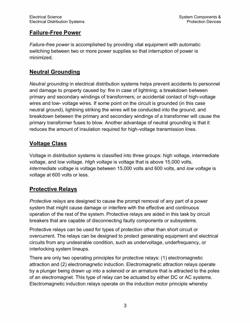
A separate zone of protection is provided around each system element (Figure 2). Any
failure that may occur within a given zone will cause the tripping or opening of all circuit
breakers within that zone. For failures that occur within a region where two protective
zones overlap, more breakers will be tripped than are necessary to disconnect the faulty
component; however, if there were no overlap of protective zones, a fault in a region
between the two zones would result in no protective action at all. Therefore, it is
desirable for protective zone overlap to ensure the maximum system protection.
Figure 2 Protective Relaying Zones
Electrical Science System Components & Electrical Distribution Systems Protection Devices
5
Fuses
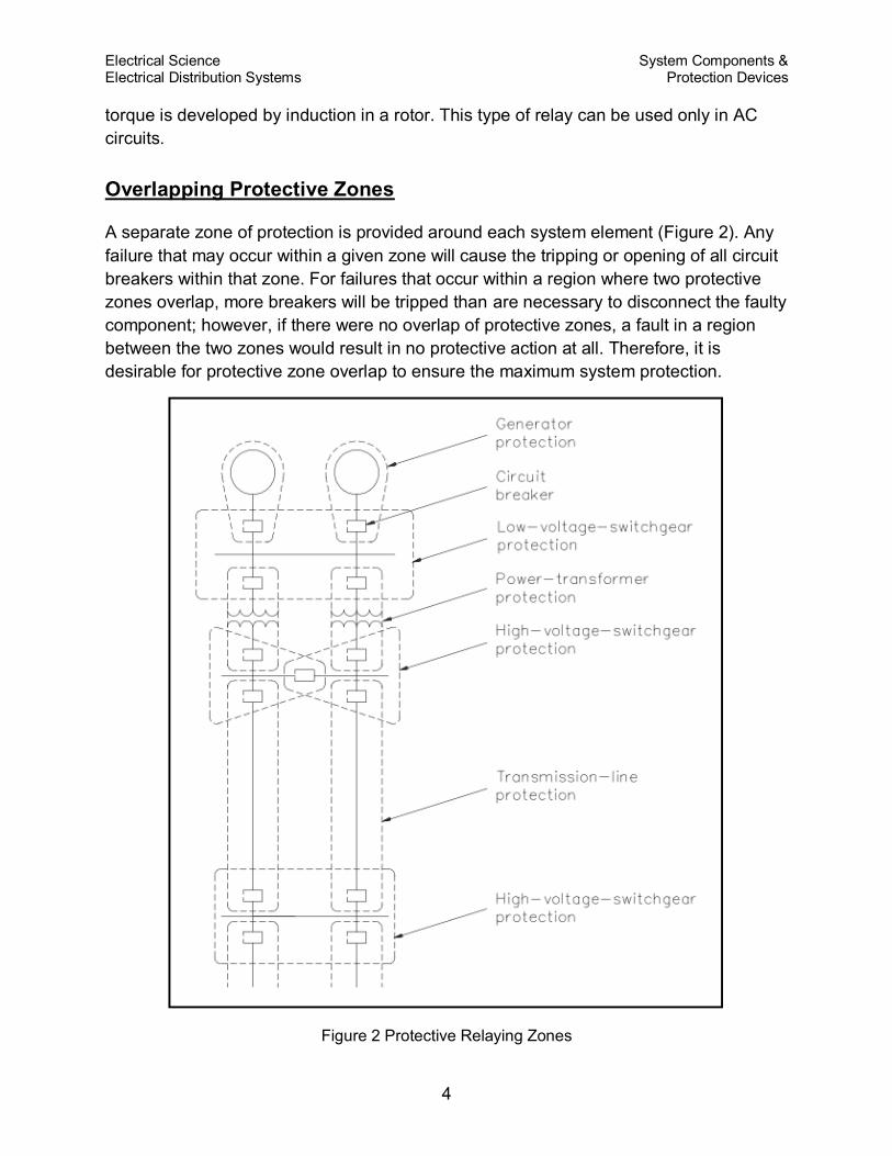
A fuse is a device that protects a circuit from an overcurrent condition only. It has a
fusible link directly heated and destroyed by the current passing through it. A fuse
contains a current-carrying element sized so that the heat generated by the flow of
normal current through it does not cause it to melt the element; however, when an
overcurrent or short-circuit current flows through the fuse, the fusible link will melt and
open the circuit. There are several types of fuses in use (Figure 3).
Figure 3 Types of Fuses
The plug fuse is a fuse that consists of a zinc or alloy strip, a fusible element enclosed
in porcelain or pyrex housing, and a screw base. This type of fuse is normally used on
circuits rated at 125 V or less to ground and has a maximum continuous current-
carrying capacity of 30 amps.
The cartridge fuse is constructed with a zinc or alloy fusible element enclosed in a
cylindrical fiber tube with the element ends attached to a metallic contact piece at the
ends of the tube. This type of fuse is normally used on circuits rated at either 250 volts
or 600 volts and has a maximum continuous current-carrying capacity of 600 amps.
Electrical Science System Components & Electrical Distribution Systems Protection Devices
6
Summary
The important information contained in this chapter is summarized below.
System Components and Protection Devices Summary
Single (one-line) diagram - simple and easy to read diagram showing power
supplies, loads, and major components in the distribution system
Commercial or utility power - electric power supplied to the facility
Diesel power - economical/practical source of standby power
Failure-free power - power supplied to vital equipment with automatic
switching so that interruption of power is minimized
Neutral grounding - helps prevent accidents to personnel and damage to
property by fire
Voltage class - high voltage > 15,000 volts, intermediate voltage is 600-15,000
volts, low voltage 600 volts
Protective relays - cause prompt removal of any part of a power system that
suffers a short circuit
Overlapping protective zones - created around each element of the power
system to prevent element failure from interrupting the whole system operation
Breakers - disconnect component from the power system
Fuse - protects component from overcurrent
Electrical Science Electrical Distribution Systems Circuit Breakers
7
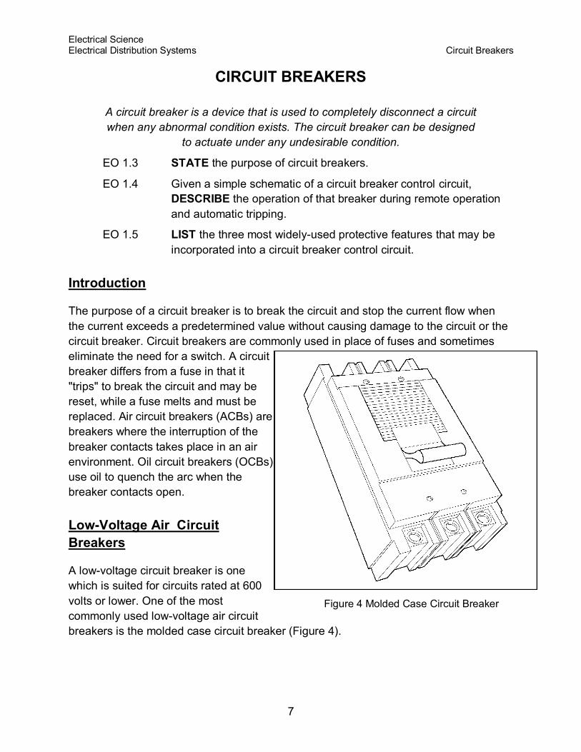
Figure 4 Molded Case Circuit Breaker
CIRCUIT BREAKERS
A circuit breaker is a device that is used to completely disconnect a circuit
when any abnormal condition exists. The circuit breaker can be designed
to actuate under any undesirable condition.
EO 1.3 STATE the purpose of circuit breakers.
EO 1.4 Given a simple schematic of a circuit breaker control circuit,
DESCRIBE the operation of that breaker during remote operation
and automatic tripping.
EO 1.5 LIST the three most widely-used protective features that may be
incorporated into a circuit breaker control circuit.
Introduction
The purpose of a circuit breaker is to break the circuit and stop the current flow when
the current exceeds a predetermined value without causing damage to the circuit or the
circuit breaker. Circuit breakers are commonly used in place of fuses and sometimes
eliminate the need for a switch. A circuit
breaker differs from a fuse in that it
"trips" to break the circuit and may be
reset, while a fuse melts and must be
replaced. Air circuit breakers (ACBs) are
breakers where the interruption of the
breaker contacts takes place in an air
environment. Oil circuit breakers (OCBs)
use oil to quench the arc when the
breaker contacts open.
Low-Voltage Air Circuit
Breakers
A low-voltage circuit breaker is one
which is suited for circuits rated at 600
volts or lower. One of the most
commonly used low-voltage air circuit
breakers is the molded case circuit breaker (Figure 4).
Electrical Science Electrical Distribution Systems Circuit Breakers
8
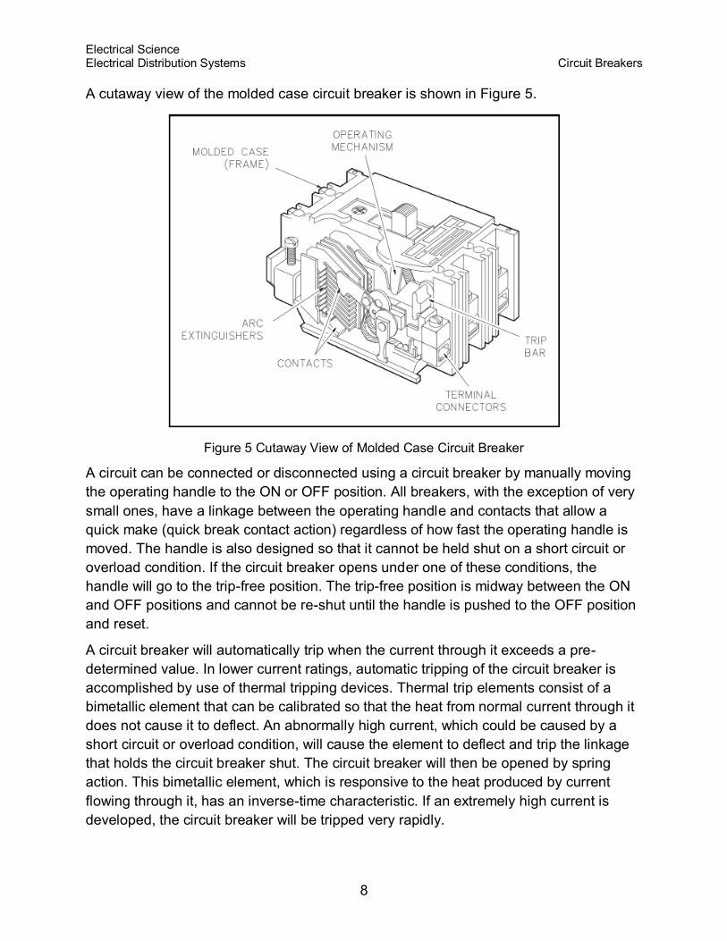
A cutaway view of the molded case circuit breaker is shown in Figure 5.
Figure 5 Cutaway View of Molded Case Circuit Breaker
A circuit can be connected or disconnected using a circuit breaker by manually moving
the operating handle to the ON or OFF position. All breakers, with the exception of very
small ones, have a linkage between the operating handle and contacts that allow a
quick make (quick break contact action) regardless of how fast the operating handle is
moved. The handle is also designed so that it cannot be held shut on a short circuit or
overload condition. If the circuit breaker opens under one of these conditions, the
handle will go to the trip-free position. The trip-free position is midway between the ON
and OFF positions and cannot be re-shut until the handle is pushed to the OFF position
and reset.
A circuit breaker will automatically trip when the current through it exceeds a pre-
determined value. In lower current ratings, automatic tripping of the circuit breaker is
accomplished by use of thermal tripping devices. Thermal trip elements consist of a
bimetallic element that can be calibrated so that the heat from normal current through it
does not cause it to deflect. An abnormally high current, which could be caused by a
short circuit or overload condition, will cause the element to deflect and trip the linkage
that holds the circuit breaker shut. The circuit breaker will then be opened by spring
action. This bimetallic element, which is responsive to the heat produced by current
flowing through it, has an inverse-time characteristic. If an extremely high current is
developed, the circuit breaker will be tripped very rapidly.
Electrical Science Electrical Distribution Systems Circuit Breakers
9
For moderate overload currents, it will operate more slowly. Molded case breakers with
much larger current ratings also have a magnetic trip element to supplement the
thermal trip element. The magnetic unit utilizes the magnetic force that surrounds the
conductor to operate the circuit breaker tripping linkage.
When the separable contacts of an air circuit breaker are opened, an arc develops
between the two contacts. Different manufacturers use many designs and
arrangements of contacts and their surrounding chambers. The most common design
places the moving contacts inside of an arc chute. The construction of this arc chute
allows the arc formed as the contacts open to draw out into the arc chute. When the arc
is drawn into the arc chute, it is divided into small segments and quenched. This action
extinguishes the arc rapidly, which minimizes the chance of a fire and also minimizes
damage to the breaker contacts.
Molded case circuit breakers come in a wide range of sizes and current ratings. There
are six frame sizes available: 100, 225, 400, 600, 800, and 2,000 amps. The size,
contact rating, and current interrupting ratings are the same for all circuit breakers of a
given frame size. The continuous current rating of a breaker is governed by the trip
element rating. The range of voltage available is from 120 to 600 volts, and interrupting
capacity ranges as high as 100,000 amps.
Much larger air circuit breakers are used in large commercial and industrial distribution
systems. These circuit breakers are available in much higher continuous current and
interrupting ratings than the molded case circuit breaker. Breakers of this type have
current ratings as high as 4,000 amps, and interrupting ratings as high as 150,000
amps.
Most large air circuit breakers use a closing device, known as a "stored energy
mechanism," for fast, positive closing action. Energy is stored by compressing large
powerful coil springs that are attached to the contact assembly of a circuit breaker.
Once these springs are compressed, the latch may be operated to release the springs,
and spring pressure will shut the circuit breaker. Circuit breaker closing springs may be
compressed manually or by means of a small electric motor. This type of circuit breaker
can be classified as either a manually- or electrically-operated circuit breaker.
When a large air circuit breaker is closed, the operating mechanism is latched. As the
circuit breaker is closed, a set of tripping springs, or coils are compressed, and the
circuit breaker may then be tripped by means of a trip latch. The trip latch mechanism
may be operated either manually or remotely by means of a solenoid trip coil.
As previously stated, circuit breakers may be operated either manually or electrically.
Electrically-operated circuit breakers are used when circuit breakers are to be operated
at frequent intervals or when remote operation is required.
Electrical Science Electrical Distribution Systems Circuit Breakers
10
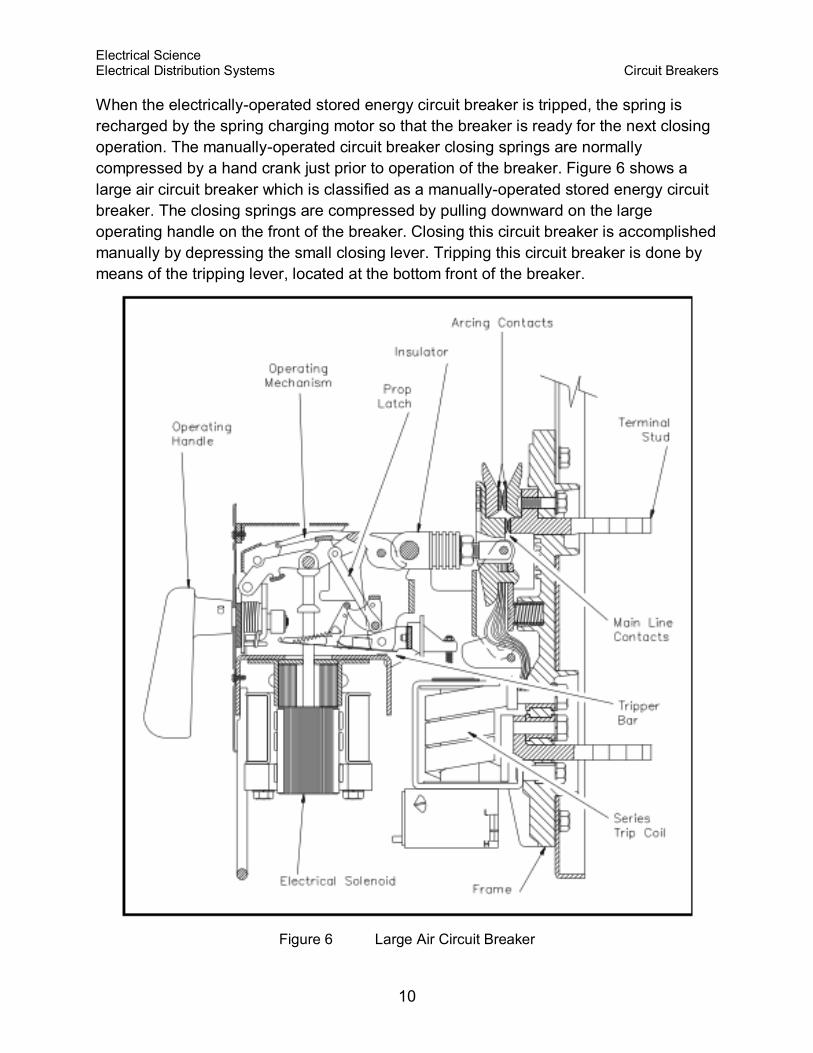
When the electrically-operated stored energy circuit breaker is tripped, the spring is
recharged by the spring charging motor so that the breaker is ready for the next closing
operation. The manually-operated circuit breaker closing springs are normally
compressed by a hand crank just prior to operation of the breaker. Figure 6 shows a
large air circuit breaker which is classified as a manually-operated stored energy circuit
breaker. The closing springs are compressed by pulling downward on the large
operating handle on the front of the breaker. Closing this circuit breaker is accomplished
manually by depressing the small closing lever. Tripping this circuit breaker is done by
means of the tripping lever, located at the bottom front of the breaker.
Figure 6 Large Air Circuit Breaker
Electrical Science Electrical Distribution Systems Circuit Breakers
11
High-Voltage Circuit Breakers
High-voltage circuit breakers (including breakers rated at intermediate voltage) are used
for service on circuits with voltage ratings higher than 600 volts. Standard voltage
ratings for these circuit breakers are from 4,160 to 765,000 volts and three-phase
interrupting ratings of 50,000 to 50,000,000 kVA.
In the early stages of electrical system development, the major portion of high-voltage
circuit breakers were oil circuit breakers. However, magnetic and compressed-air type
air circuit breakers have been developed and are in use today.
The magnetic air circuit breaker is rated up to 750,000 kVA at 13,800 volts. This type of
circuit breaker interrupts in air between two separable contacts with the aid of magnetic
blowout coils. As the current-carrying contacts separate during a fault condition, the arc
is drawn out horizontally and transferred to a set of arcing contacts. Simultaneously, the
blowout coil provides a magnetic field to draw the arc upward into the arc chutes. The
arc, aided by the blowout coil magnetic field and thermal effects, accelerates upward
into the arc chute, where it is elongated and divided into many small segments.
The construction of this type of circuit breaker is similar to that of a large air circuit
breaker used for low-voltage applications, except that they are all electrically operated.
Compressed-air circuit breakers, or air-blast circuit breakers, depend on a stream of
compressed air directed toward the separable contacts of the breaker to interrupt the
arc formed when the breaker is opened. Air-blast circuit breakers have recently been
developed for use in extra high-voltage applications with standard ratings up to 765,000
volts.
Oil circuit breakers (OCBs) are circuit breakers that have their contacts immersed in oil.
Current interruption takes place in oil which cools the arc developed and thereby
quenches the arc. The poles of small oil circuit breakers can be placed in one oil tank;
however, the large high-voltage circuit breakers have each pole in a separate oil tank.
The oil tanks in oil circuit breakers are normally sealed. The electrical connections
between the contacts and external circuits are made through porcelain bushings.
Circuit Breaker Control
As we have discussed, circuit breakers may be remotely operated. In order to operate
the breakers from a remote location, there must be an electrical control circuit
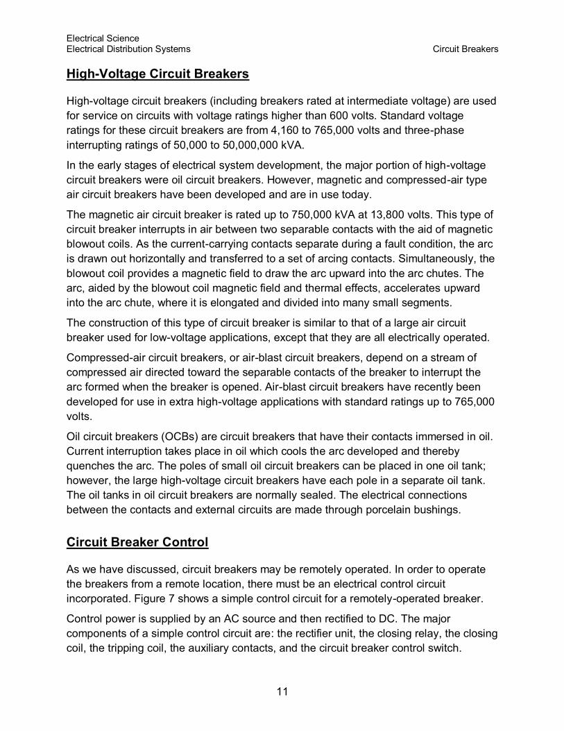
incorporated. Figure 7 shows a simple control circuit for a remotely-operated breaker.
Control power is supplied by an AC source and then rectified to DC. The major
components of a simple control circuit are: the rectifier unit, the closing relay, the closing
coil, the tripping coil, the auxiliary contacts, and the circuit breaker control switch.
Electrical Science Electrical Distribution Systems Circuit Breakers
12
Figure 7 Simple Circuit Breaker Control Circuit Breaker Open
To close the remotely-operated circuit breaker, turn the circuit breaker control switch to
the close position. This provides a complete path through the closing relay (CR) and
energizes the closing relay. The closing relay shuts an auxiliary contact, which
energizes the closing coil (CC), which, in turn, shuts the circuit breaker, as shown in
Figure 8. The breaker latches in the closed position. Once the breaker is shut, the "b"
contact associated with the closing relay opens, de-energizing the closing relay and,
thereby, the closing coil. When the breaker closes, the "a" contact also closes, which
enables the trip circuit for manual or automatic trips of the breaker. The circuit breaker
control switch may now be released and will automatically return to the neutral position.
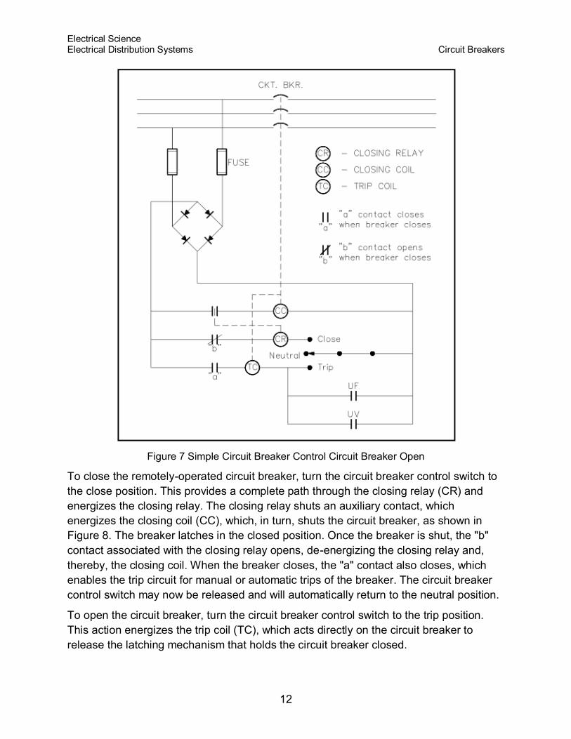
To open the circuit breaker, turn the circuit breaker control switch to the trip position.
This action energizes the trip coil (TC), which acts directly on the circuit breaker to
release the latching mechanism that holds the circuit breaker closed.
Electrical Science Electrical Distribution Systems Circuit Breakers
13
When the latching mechanism is released, the circuit breaker will open, opening the "a"
contact for the tripping coil and de-energizing the tripping coil. Also, when the circuit
breaker opens, the "b" contact will close, thereby setting up the circuit breaker to be
remotely closed using the closing relay, when desired. The circuit breaker control switch
may now be released.
Figure 8 Simple Circuit Breaker Control Circuit - Breaker Closed
As you can see from Figure 7 or 8, the circuit breaker control circuit can be designed so
that any one of a number of protective features may be incorporated. The three most
commonly-used automatic trip features for a circuit breaker are overcurrent (as
discussed previously), underfrequency, and undervoltage. If any one of the conditions
exists while the circuit breaker is closed, it will close its associated contact and energize
the tripping coil, which, in turn, will trip the circuit breaker.
Electrical Science Electrical Distribution Systems Circuit Breakers
14
Summary
The important information covered in this chapter is summarized below.
Circuit Breaker Summary
The purpose of a circuit breaker is to provide a means for connecting and
disconnecting circuits of relatively high capacities without causing damage to
them.
The three most commonly-used automatic trip features for a circuit breaker are
overcurrent, underfrequency, and undervoltage.
Electrical Science Electrical Distribution Systems Motor Controllers
15
MOTOR CONTROLLERS
Motor controllers range from a simple toggle switch to a complex system
using solenoids, relays, and timers. The basic functions of a motor
controller are to control and protect the operation of a motor.
EO 1.6 STATE the function of motor controllers.
EO 1.7 STATE three protective features (overloads) that may be
incorporated into a motor controller.
EO 1.8 Given a simplified drawing of a motor controller, DESCRIBE the
operation of that motor controller.
Motor Controllers
Motor controllers range from a simple toggle switch to a complex system using
solenoids, relays, and timers. The basic functions of a motor controller are to control
and protect the operation of a motor. This includes starting and stopping the motor, and
protecting the motor from overcurrent, undervoltage, and overheating conditions that
would cause damage to the motor. There are two basic categories of motor controllers:
the manual controller and the magnetic controller.
Manual Controllers
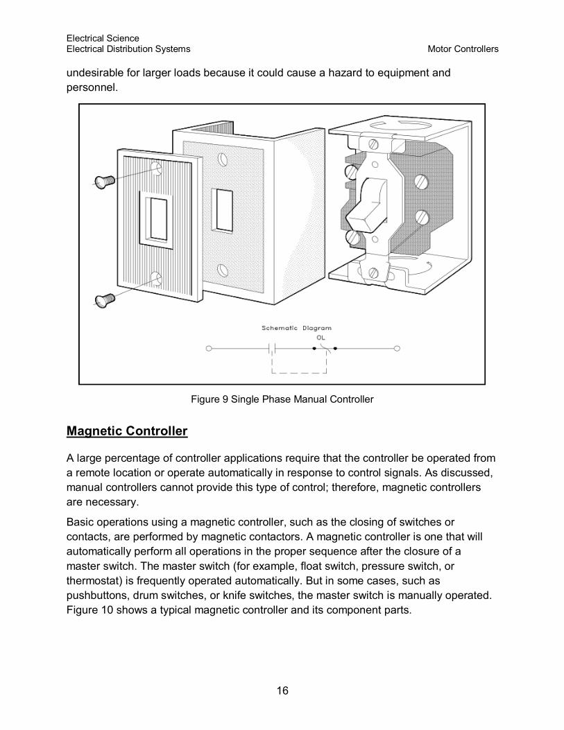
A manual controller, illustrated by Figure 9, is a controller whose contact assembly is
operated by mechanical linkage from a toggle-type handle or a pushbutton
arrangement. The controller is operated by hand.
The manual controller is provided with thermal and direct-acting overload units to
protect the motor from overload conditions. The manual controller is basically an "ON-
OFF" switch with overload protection.
Manual controllers are normally used on small loads such as machine tools, fans,
blowers, pumps, and compressors. These types of controllers are simple, and they
provide quiet operation. The contacts are closed simply by moving the handle to the
"ON" position or pushing the START button. They will remain closed until the handle is
moved to the "OFF" position or the STOP button is pushed. The contacts will also open
if the thermal overload trips.
Manual controllers do NOT provide low voltage protection or low voltage release. When
power fails, the manual controller contacts remain closed, and the motor will restart
when power is restored. This feature is highly desirable for small loads because
operator action is not needed to restart the small loads in a facility; however, it is
Electrical Science Electrical Distribution Systems Motor Controllers
16
undesirable for larger loads because it could cause a hazard to equipment and
personnel.
Figure 9 Single Phase Manual Controller
Magnetic Controller
A large percentage of controller applications require that the controller be operated from
a remote location or operate automatically in response to control signals. As discussed,
manual controllers cannot provide this type of control; therefore, magnetic controllers
are necessary.
Basic operations using a magnetic controller, such as the closing of switches or
contacts, are performed by magnetic contactors. A magnetic controller is one that will
automatically perform all operations in the proper sequence after the closure of a
master switch. The master switch (for example, float switch, pressure switch, or
thermostat) is frequently operated automatically. But in some cases, such as
pushbuttons, drum switches, or knife switches, the master switch is manually operated.
Figure 10 shows a typical magnetic controller and its component parts.
Electrical Science Electrical Distribution Systems Motor Controllers
17
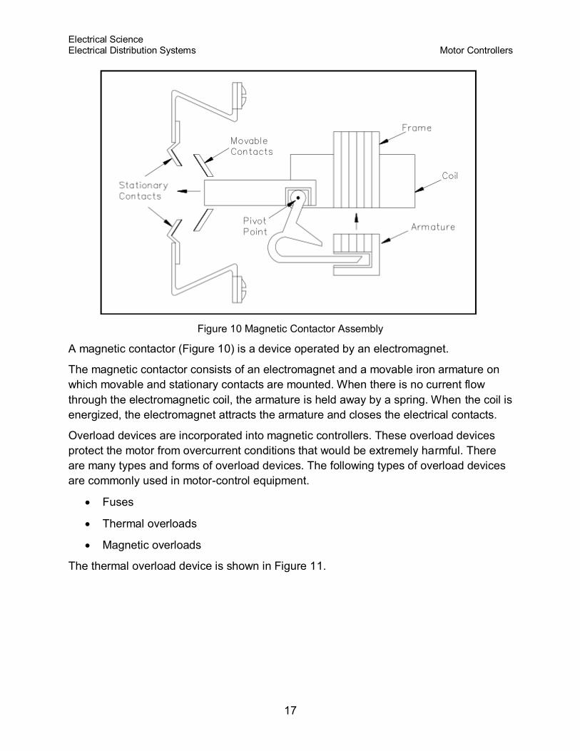
Figure 10 Magnetic Contactor Assembly
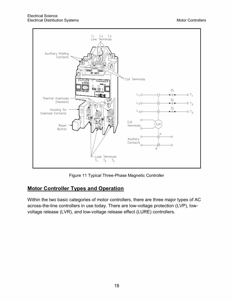
A magnetic contactor (Figure 10) is a device operated by an electromagnet.
The magnetic contactor consists of an electromagnet and a movable iron armature on
which movable and stationary contacts are mounted. When there is no current flow
through the electromagnetic coil, the armature is held away by a spring. When the coil is
energized, the electromagnet attracts the armature and closes the electrical contacts.
Overload devices are incorporated into magnetic controllers. These overload devices
protect the motor from overcurrent conditions that would be extremely harmful. There
are many types and forms of overload devices. The following types of overload devices
are commonly used in motor-control equipment.
Fuses
Thermal overloads
Magnetic overloads
The thermal overload device is shown in Figure 11.
Electrical Science Electrical Distribution Systems Motor Controllers
18
Figure 11 Typical Three-Phase Magnetic Controller
Motor Controller Types and Operation
Within the two basic categories of motor controllers, there are three major types of AC
across-the-line controllers in use today. There are low-voltage protection (LVP), low-
voltage release (LVR), and low-voltage release effect (LURE) controllers.
Electrical Science Electrical Distribution Systems Motor Controllers
19
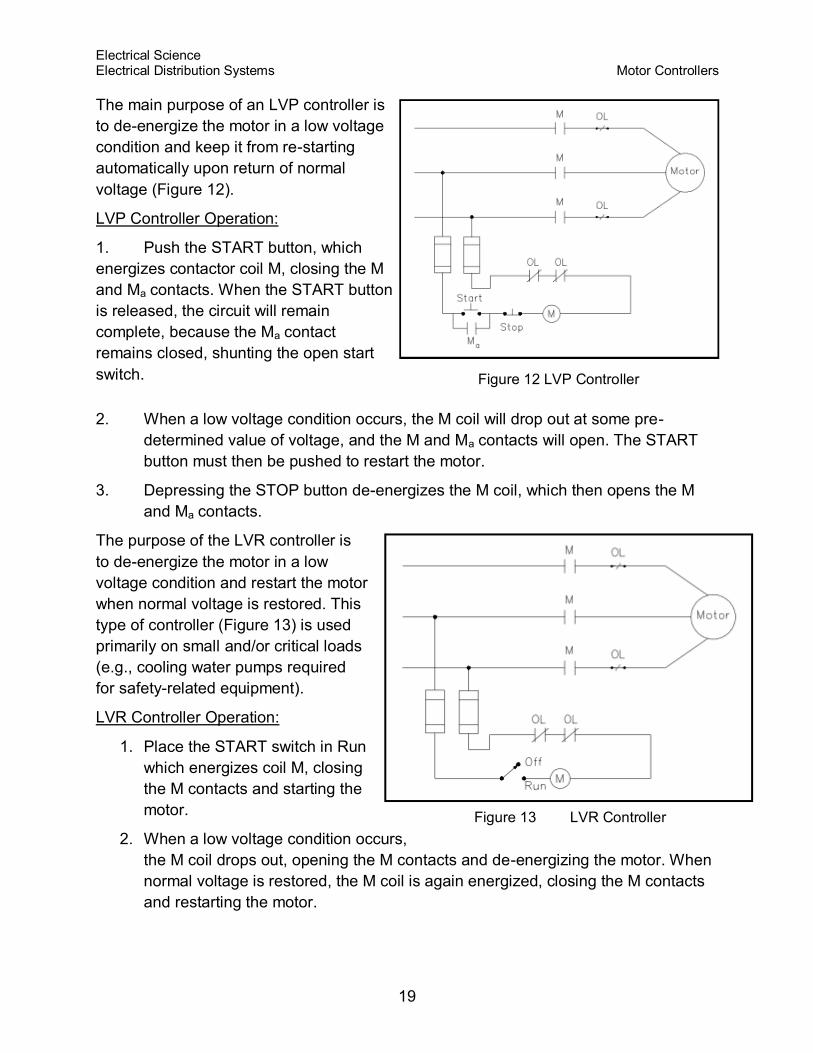
The main purpose of an LVP controller is
to de-energize the motor in a low voltage
condition and keep it from re-starting
automatically upon return of normal
voltage (Figure 12).
LVP Controller Operation:
1. Push the START button, which
energizes contactor coil M, closing the M
and Ma contacts. When the START button
is released, the circuit will remain
complete, because the Ma contact
remains closed, shunting the open start
switch.
Figure 12 LVP Controller
2. When a low voltage condition occurs, the M coil will drop out at some pre-
determined value of voltage, and the M and Ma contacts will open. The START
button must then be pushed to restart the motor.
3. Depressing the STOP button de-energizes the M coil, which then opens the M
and Ma contacts.
The purpose of the LVR controller is
to de-energize the motor in a low
voltage condition and restart the motor
when normal voltage is restored. This
type of controller (Figure 13) is used
primarily on small and/or critical loads
(e.g., cooling water pumps required
for safety-related equipment).
LVR Controller Operation:
1. Place the START switch in Run
which energizes coil M, closing
the M contacts and starting the
motor.
2. When a low voltage condition occurs,
the M coil drops out, opening the M contacts and de-energizing the motor. When
normal voltage is restored, the M coil is again energized, closing the M contacts
and restarting the motor.
Figure 13 LVR Controller
Electrical Science Electrical Distribution Systems Motor Controllers
20
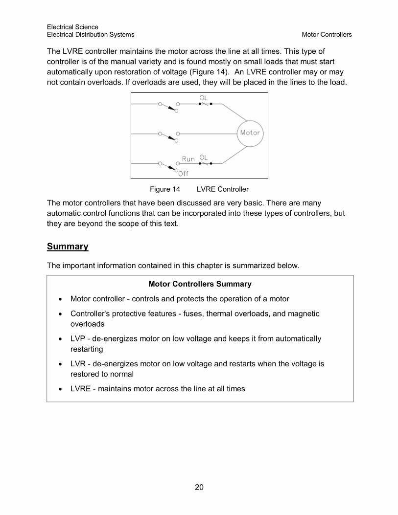
The LVRE controller maintains the motor across the line at all times. This type of
controller is of the manual variety and is found mostly on small loads that must start
automatically upon restoration of voltage (Figure 14). An LVRE controller may or may
not contain overloads. If overloads are used, they will be placed in the lines to the load.
Figure 14 LVRE Controller
The motor controllers that have been discussed are very basic. There are many
automatic control functions that can be incorporated into these types of controllers, but
they are beyond the scope of this text.
Summary
The important information contained in this chapter is summarized below.
Motor Controllers Summary
Motor controller - controls and protects the operation of a motor
Controller's protective features - fuses, thermal overloads, and magnetic
overloads
LVP - de-energizes motor on low voltage and keeps it from automatically
restarting
LVR - de-energizes motor on low voltage and restarts when the voltage is
restored to normal
LVRE - maintains motor across the line at all times
Electrical Science Wiring Schemes Electrical Distribution Systems & Grounding
21
WIRING SCHEMES AND GROUNDING
Nuclear facilities rely on standardized wiring schemes to provide both
single-phase and three-phase power distribution systems and protective
grounds to insure safe operation.
EO 1.9 DEFINE the following terms as they apply to wiring schemes used
in power distribution systems:
a. Ampacity
b. Bond
c. Conductor
d. Ground
e. Ground voltage
f. Leg
g. Neutral
h. Phase voltage
EO 1.10 DESCRIBE the two methods of connecting single-phase loads to a
three-phase power source.
EO 1.11 DESCRIBE the purpose of the following power distribution
schemes.
a. 3-wire, single-phase Edison system
b. 3-wire, three-phase Delta system
c. 4-wire, three-phase Delta system
d. 4-wire, three-phase Wye system
Introduction
Many advisory boards exist to insure the standardization of electrical installations in
accordance with accepted designs and safe practices. The Institute of Electrical and
Electronics Engineers (IEEE) and the American National Standards Institute (ANSI) are
two advisory boards that have published numerous standards. These standards are
utilized by the Department of Energy and the nuclear industry. However, for a day-to-
day practical guide for noncritical installations, the recognized guide is the National
Electrical Code Handbook (NEC), published by the National Fire Protection Association
and endorsed by ANSI. The NEC Handbook is the primary source of much of the
Electrical Science Wiring Schemes Electrical Distribution Systems & Grounding
22
material presented in this chapter and may serve as a ready reference for specific
questions not covered in this fundamental discussion.
Terminology
To understand wiring schemes used in power distribution systems, you must be familiar
with the following terms.
Ampacity - the current in amperes that a conductor can carry continuously under
the conditions of use without exceeding its temperature rating.
Bond - the permanent joining of metallic parts or circuits assuring electrical
continuity and capacity to safely conduct any current likely to be imposed.
Conductor - any wire, cable, or substance capable of carrying an electrical
current.
Ground - a conducting connection, whether intentional or accidental, between a
circuit or piece of equipment and the earth, or some body serving as earth; a
place of zero electrical potential.
Ground voltage - the voltage between any given conductor and any point at
ground potential.
Leg - a current-carrying conductor intended to deliver power to or from a load
normally at an electrical potential other than ground.
Neutral - a current-carrying conductor normally tied to ground so that the
electrical potential is zero.
Phase voltage - the greatest root mean square (effective) difference of potential
between any two legs of the circuit.
Single-Phase Power
The source of single-phase (1Φ) power in all facilities is by generation from a single-
phase generator or by utilization of one phase of a three-phase (3Φ) power source.
Basically, each phase of the 3Φ distribution system is a single-phase generator
electrically spaced 120 degrees from the other two; therefore, a 3Φ power source is
convenient and practical to use as a source of single-phase power.
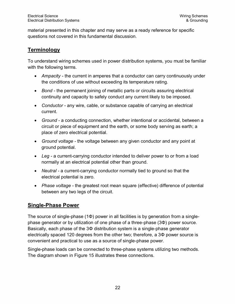
Single-phase loads can be connected to three-phase systems utilizing two methods.
The diagram shown in Figure 15 illustrates these connections.
Electrical Science Wiring Schemes Electrical Distribution Systems & Grounding
23
Figure 15 Three-Phase to Single-Phase Connections
The first scheme (Figure 15A) provides for the connection of the load from a phase leg
to any ground point and is referred to as a phase-to-ground scheme. The remaining
scheme (Figure 15B) connects the single-phase load between any two legs of the three-
phase source and is referred to as a phase-to-phase connection. The choice of
schemes, phase-to phase or phase-to-ground, allows several voltage options
depending on whether the source three-phase system is a delta or wye configuration.
This will be discussed in the three-phase segment of this chapter.
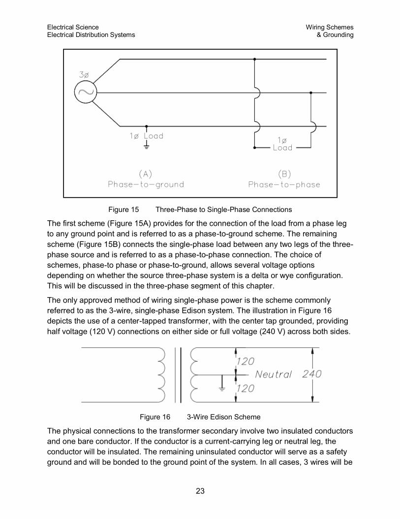
The only approved method of wiring single-phase power is the scheme commonly
referred to as the 3-wire, single-phase Edison system. The illustration in Figure 16
depicts the use of a center-tapped transformer, with the center tap grounded, providing
half voltage (120 V) connections on either side or full voltage (240 V) across both sides.
Figure 16 3-Wire Edison Scheme
The physical connections to the transformer secondary involve two insulated conductors
and one bare conductor. If the conductor is a current-carrying leg or neutral leg, the
conductor will be insulated. The remaining uninsulated conductor will serve as a safety
ground and will be bonded to the ground point of the system. In all cases, 3 wires will be
Electrical Science Wiring Schemes Electrical Distribution Systems & Grounding
24
presented to the load terminals, and the safety ground will be bonded to each junction
box, or device, in the distribution system. In the case of half voltage (120 V) use, the
intended path of the current is from the supply leg through the load and back to the
source on the neutral leg. No current would be carried on the ground unless a fault
occurred in the system, in which case the current would flow safely to ground.
In the full voltage system (240 V), the insulated conductors are connected across the
full winding of the transformer, and the uninsulated conductor is again bonded to the
grounded center tap. In a balanced system, all currents will flow on the insulated
conductors, and the grounded neutral will carry no current, acting only in a ground
capacity. In the case of either an unbalanced load or a fault in the system, the bare
conductor will carry current, but the potential will remain at zero volts because it is tied
to the ground point. As in the case of the half voltage system, the uninsulated conductor
will be bonded to each device in the system for safety.
Three-Phase Wiring Schemes
Unlike the single-phase wiring scheme that must make a provision for a neutral leg and
separate ground, the three-phase system needs neither a separate neutral nor a ground
to operate safely. However, to prevent any unsafe condition, all 3- and 4-wire, three-
phase systems can include an effective ground path. As with the previous single-phase
discussion, only the secondary side of the transformer and its connected load need to
be studied.
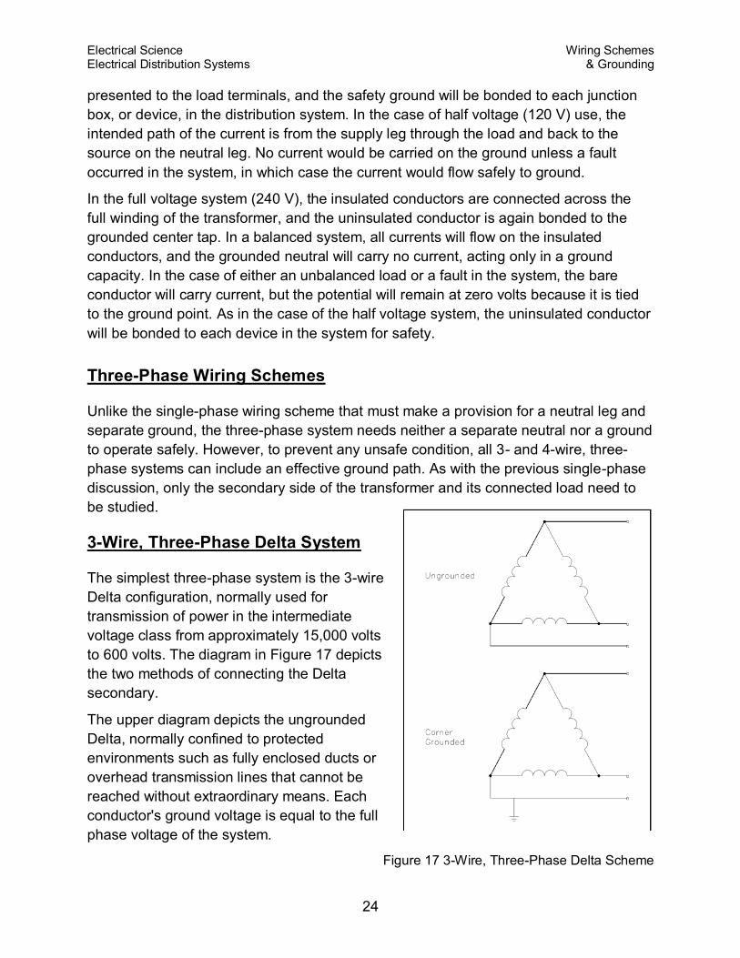
3-Wire, Three-Phase Delta System
The simplest three-phase system is the 3-wire
Delta configuration, normally used for
transmission of power in the intermediate
voltage class from approximately 15,000 volts
to 600 volts. The diagram in Figure 17 depicts
the two methods of connecting the Delta
secondary.
The upper diagram depicts the ungrounded
Delta, normally confined to protected
environments such as fully enclosed ducts or
overhead transmission lines that cannot be
reached without extraordinary means. Each
conductor's ground voltage is equal to the full
phase voltage of the system.
Figure 17 3-Wire, Three-Phase Delta Scheme
Electrical Science Wiring Schemes Electrical Distribution Systems & Grounding
25
The lower diagram shows a ground point affixed to one corner of the Delta, which
effectively lowers one phase's voltage reference to ground to zero, but retains a phase-
to-phase voltage potential. The corner-grounded phase acts in much the same way as
the grounded neutral of the single-phase Edison system, carrying current and
maintaining ground potential.
The corner-grounded Delta system has an obvious economy in wiring costs, and the
grounded phase can be used to physically protect the other two phases from accidental
grounding or lightning strikes in outdoor settings. This system is rarely used for low
voltage (under 600 V), however, because of the absence of a safety ground required by
many facilities for circuits involving potential worker contact.
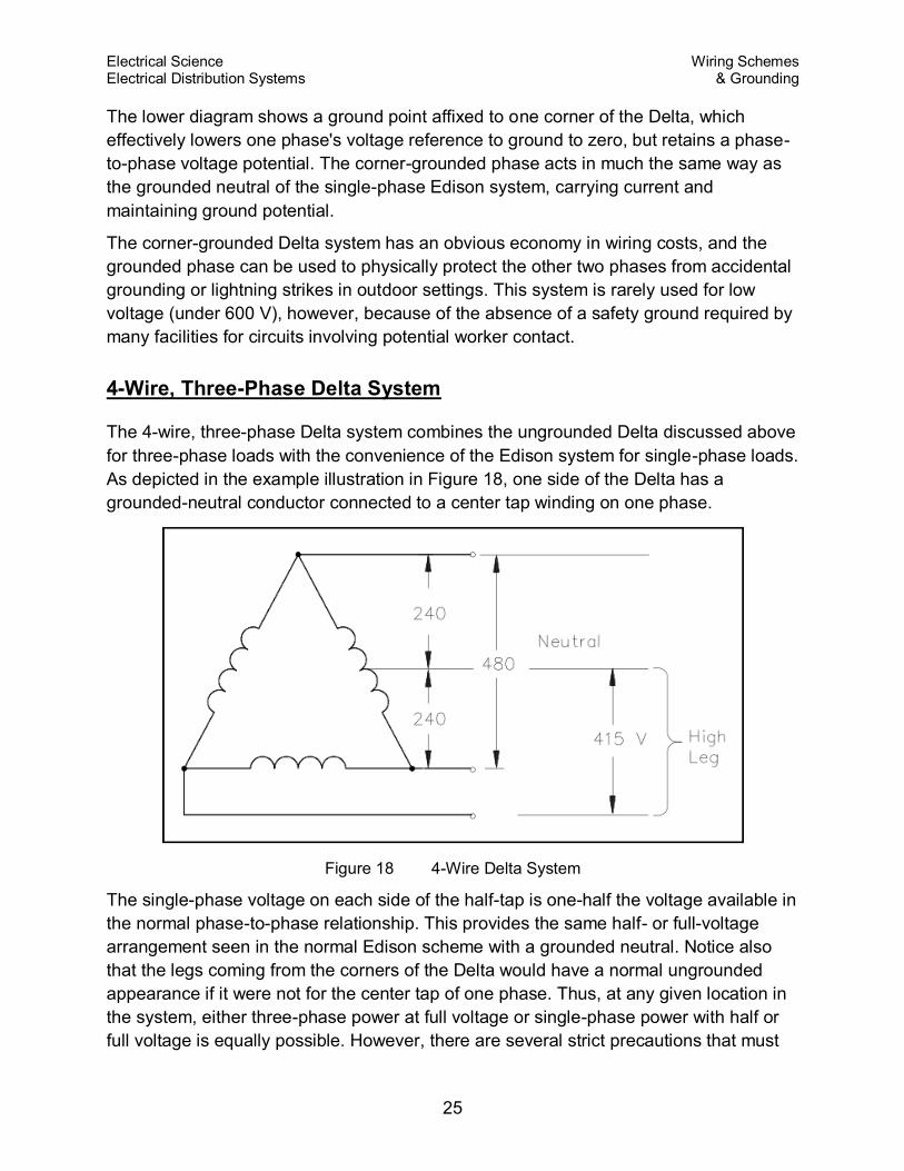
4-Wire, Three-Phase Delta System
The 4-wire, three-phase Delta system combines the ungrounded Delta discussed above
for three-phase loads with the convenience of the Edison system for single-phase loads.
As depicted in the example illustration in Figure 18, one side of the Delta has a
grounded-neutral conductor connected to a center tap winding on one phase.
Figure 18 4-Wire Delta System
The single-phase voltage on each side of the half-tap is one-half the voltage available in
the normal phase-to-phase relationship. This provides the same half- or full-voltage
arrangement seen in the normal Edison scheme with a grounded neutral. Notice also
that the legs coming from the corners of the Delta would have a normal ungrounded
appearance if it were not for the center tap of one phase. Thus, at any given location in
the system, either three-phase power at full voltage or single-phase power with half or
full voltage is equally possible. However, there are several strict precautions that must
Electrical Science Wiring Schemes Electrical Distribution Systems & Grounding
26
be observed in the operation of this system. First, all loads must be carefully balanced
on both the single-phase and three-phase legs. Second, because the voltage between
one leg and the grounded neutral is considerably higher than the rest of the single-
phase system, a measurement between the neutral and the phase must be taken to
identify the "high leg," or "bastard voltage." Last, the "high leg" is never used as a
single-phase source because no ground or grounded neutral exists for this circuit.
4-Wire, Three-Phase Wye System
Until now, the voltage, the phase voltage, and the ground voltage of the three-phase
systems have been equal, with the one exception of one phase of the corner-grounded
Delta. The Wye system has completely different voltage characteristics from the Delta
system. In the Wye system, the ground voltage or voltage available from phase to
ground is the phase voltage divided by 1.73.
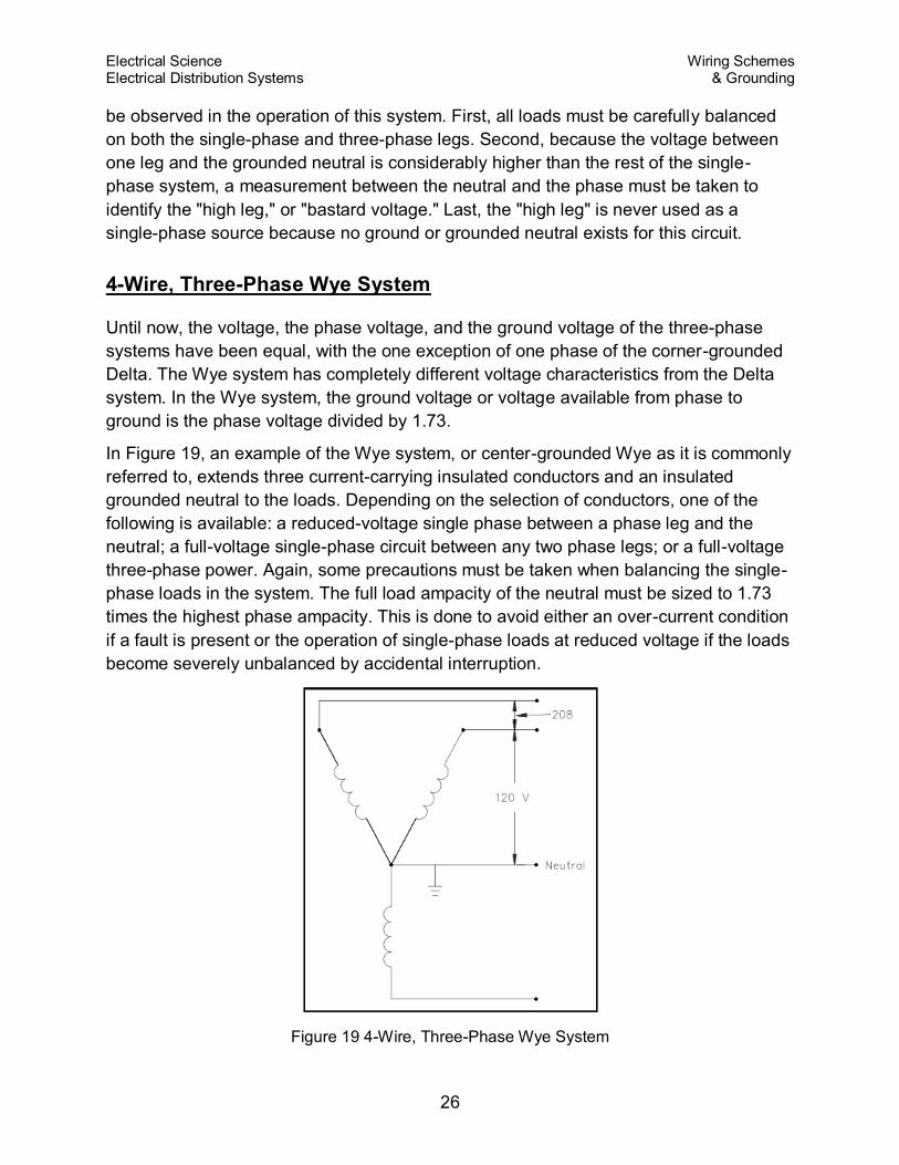
In Figure 19, an example of the Wye system, or center-grounded Wye as it is commonly
referred to, extends three current-carrying insulated conductors and an insulated
grounded neutral to the loads. Depending on the selection of conductors, one of the
following is available: a reduced-voltage single phase between a phase leg and the
neutral; a full-voltage single-phase circuit between any two phase legs; or a full-voltage
three-phase power. Again, some precautions must be taken when balancing the single-
phase loads in the system. The full load ampacity of the neutral must be sized to 1.73
times the highest phase ampacity. This is done to avoid either an over-current condition
if a fault is present or the operation of single-phase loads at reduced voltage if the loads
become severely unbalanced by accidental interruption.
Figure 19 4-Wire, Three-Phase Wye System
Electrical Science Wiring Schemes Electrical Distribution Systems & Grounding
27
As with all other grounded systems, bonds are established between the grounded
neutral and all components of the system. This system is recognized as the safest
possible multi-purpose distribution system for low voltage and is commonly seen in the
208/120-volt range in many facilities.
Summary
The important information in this chapter is summarized on the following page.
Wiring Schemes And Grounding Summary
Terminology
Ampacity - current-carrying capacity of a conductor in amperes
Bond - permanent joining of metallic parts or circuits assuring electrical continuity
Conductor - any wire, cable, or substance capable of carrying an electrical
current
Ground - a conducting connection between a circuit or piece of equipment and
the earth, or somebody serving as earth
Ground voltage - the voltage between any given conductor and any point at
ground potential
Leg - a current-carrying conductor intended to deliver power to or from a load
Neutral - a current-carrying conductor intended to deliver power to or from a load
normally at an electrical potential other than ground
Phase voltage - the greatest root mean square (effective) difference of potential
between any two legs of the circuit
Two methods to connect single-phase loads to a three-phase system are:
Phase-to-phase
Phase-to-ground
The purposes of the following wiring schemes are:
3-wire, single-phase Edison system - the only approved method of wiring single-
phase power
3-wire, three-phase Delta system - normally used for transmission of power in the
intermediate voltage class from approximately 15,000 volts to 600 volts
4-wire, three-phase Delta system - combines the ungrounded Delta for three-
phase loads with the convenience of the Edison system for single-phase loads
4-wire, three-phase Wye system - the safest possible multi-purpose distribution
system for low voltage