Embed Size (px)
Citation preview

,,
CFCC APPLICATIONS FOR DIESEL ENGINE VALVE GUIDES
DOE Continuous Fiber Ceramic Composite Program
Phase IIA/B
Final Report
April 14,1999
Doug Twait and Michael Long*
. sUBMITTED TO
DEPARTMENT OF ENERGYUNDER COOPERA~ AGREEMENT No. DE-FCO2-92CE41OO2
BY
ALLIEDSIGNAL hlC., CERAMIC COMPONENTS
*CA~~~L~ Inc.
— ..——... —. ,...- .--,-... .,.,,. ... ~ ,..,,. .-m-l, - . .. . . . . . . -.-,-2-— , .R?7K-. ‘..- .-’;-.. n-----. ..—

DISCLAIMER
This report was.prepared as an account of work sponsoredby an agency of the United States Government. Neitherthe United States Government nor any agency thereof, norany of their employees, make any warranty, express orimplied, or assumes any legal liability or responsibility forthe accuracy, completeness, or usefulness of anyinformation, apparatus, product, or process disclosed, orrepresents that its use would not infringe privately ownedrights. Reference herein to any specific commercialproduct, process, or service by trade name, trademark,manufacturer, or otherwise does not necessarily constituteor imply its endorsement, recommendation, or favoring bythe United States Government or any agency thereof. Theviews and opinions of authors expressed herein do notnecessarily state or reflect those of the United StatesGovernment or any agency thereof.

DISCLAIMER
Portions of this document may be illegiblein electronic image products. Images areproduced from the best available originaldocument.

(
TABLE OF CONTENTS
List of FiguresList of TablesExecutive Summary
l.O Introduction2.0 Background3.0 Phase II A/B Technical Progress
3.1 Introduction3.2 Process Optimization for Manufacturing (Task 3.2)
3.2.1 Net Shape Fabrication Optimization3.2.1.1 Cold Isostatic Pressing3.2.1.2 Gelcasting
3.2.2 Evaluation3.3 Component Fabrication and Testing (Task 3.3)
3.3.1 Specimen and Prototype Valve Guide Fabrication3.3.2 Wear Coefilcient3.3.3 Mechanical Property3.3.4 Durability Test
3.3.4.1 Baseline Test3.3.4.2 Lubricated Durability Test3.3.4.3 Restricted Lubrication Durability Test3.3.4.4 Durability Test Summary
3.3.5 Selection of CFCC Valve Guides3.4 Component Evaluation (Task 3.4)
3.4.1 Engine Selection3.4.2 Final Design3.4.3 Engine Assembly3.4.4 Engine Test
3.4.4.1 Engine Test 1 – 224 hrs.3.4.4.2 Engine Test 2 – 528 hrs.
3.4.5 Data Analysis /Recommendation3.4.5.1 CTE Mismatch Affecting Guide Stem Clearance3.4.5.2 Geometry and Material Break-in Differences3.4.5.3 Material Variation
3.4.6 Expanded Bench Testing3.4.6.1 ORNL Ball-on-Flat Testing3.4.6.2 Caterpillar Cameron Plint Testing
4.0 Summary of Phase IIA/B Accomplishments
References
Appendix
@edSignal
---.-1-. ,...m-.
Page356
8912121212
181818202226
333333343536
42
54
59
60
61
2
--- ------- —

LIST OF FIGURES
Figure
3.2.1.1-13.2.1.1-2
3.3.1.2-13.3.2-13.3.3-1
3.3.3-2
3.3.4.1-1
3.4.1-13.4.2-13.4.4.1-13.4.4.2-13.4.5-13.4.5-23.4.5.1-13.4.5.1-23.4.5.1-33.4.5.1-43.4.5.2-1
3.4.5.2-2
3.4.5.3-13.4.5.3-2
3.4.6-1
3.4.6.2-13.4.6.2-2
The baseline CFCC valve guide fabrication process flow chartImprovements to the baseline fabrication process results in lessWarpageExamples of the CFCC valve guides fabricated under Task 3.3.1.2Valve Stem and Guide Sections Used in the Cameron-Plint TestSilicon Nitride with 10 volume percent Carbon Fiber–231 MPabreaking stress; SEM MOR bar fracture surfaces at lOOxand 500x.Silicon Nitride with 12.5 volume percent Carbon Fiber –234 Mpa breaking stress; SEM MOR bar fracture stiaces at 10OXand 500x.Battelle Durability Test – Motorized 3500 Series CylinderHead.3508 Series EngineFinal Valve Guide DesignValve Guide Configuration for Engine Test 1 – 224 HoursValve Guide Cor@guration for Engine Test 2 – 528 HoursIntake and Exhaust Guide Wear for Test 1 and 2.Intake and Exhaust Stem Wear for Test 1 and 2.Test 1 – Intake and Exhaust Guide Wear Versus ClearanceTest 1 – Intake and Exhaust Stem Wear Versus ClearanceTest 2 – Intake and Exhaust Guide Wear Versus ClearanceTest 2 – Intake and Exhaust Stem Wear Versus ClearanceInner Diameter (ID) trace of 224 hour CFCC (left) and castiron guide (right).Valve Guide Measurement Locations For DeterminingWear at Guide BottomMicrostructure of CFCC valve guide inner diameter.Microstructure of silicon nitride valve guide inner diameter fromthe 528 hour engine test.Cameron-Plint Test Fixture Schematic for Holding ValveGuide and StemCameron-Plint Bench TestWear Scars on Valve Stem and Guide after Testing - Lubricated
3.4.6.2-3 Wear Scars on Valve Stem and Guide after Testing - Dry
page
14
152021
24
25
2734353739424346464747
49
5052
53
55575858
@liedSignal 3
- - ~.-m. --m .,- . ... .,,-7-7?--- ..7 .-,. :--.,-,------- -.7.7=.- .7... . ,,..,. <‘ic.....7. . ...RkT77s=...., ,:...—--.. TJ+.,. . --—”””—’-- -

LIST OF TABLES
Table page
3.3.2-13.3.2-23.3.3-1
3.3.4.1-1
3.3.4.2-1
3.3.4.2-2
3.3.4.2-3
3.3.4.2-4
3.4.1-13.4.3-13.4.4.1-13.4.4.1-23.4.4.2-13.4.4.2-23.4.5.1-13.4.5.2-13.4.6.2-13.4.6.2-2
Cameron-Plint Test ConditionsCameron-Plint Friction and Wear Test ResultsMechanical Properties of GS-44 Silicon Nitride Densified TubesW/various Amounts of Amoco P-75 Carbon FibersValve Guide and Stem Wear from 100 hour Baseline DurabilityTest.Valve Guide and Stem Wear after 100 and 200 hours ofDurability Test l/Lubricated.Valve Guide and Stem Wear after 100 and 200 hours ofDurability Test 2/Lubricated.Valve Guide and Stem Wear after 100 and 200 hours ofDurability Test 3/Restricted Lubrication.Valve Guide and Stem Wear after 200 hours ofDurability Test 4/Restricted Lubrication.3500 Series Natural Gas Engine SpecificationsSurface Inspection of Machined Valve GuidesEngine Test 1 Results – Guide WearEngine Test 1 Results – Stem WearEngine Test 2 Results – Guide WearEngine Test 2 Results – Stem WearClearance Change versus Temperature and MaterialInner Diameter Measurements of 528 Hour HardwareCameron Plint Test ConditionsFriction Coei%cient Results for Cameron-Plint Bench Test –Lubricated
2222
23
28
29
30
31
32333638384141445056
57
@liedSignal 4
—--- r --: ,G%..ma=!m-. ~~;. .n’’y-—-<.=.,! .. ,, : ,-- -

Executive Summary
The driving forces for diesel and alternative fiel technology are reliability,durability, efficiency, and emission regulations. The self-lubricating exhaust valveguides technology was expected to increase the reliability and durability of advanced,fiel efllcient diesel engines and diesel engines which use low emission fuels. For thisreason, the objective of this program was to develop a self-lubricating carbon fiber/silicon nitride composite exhaust valve guide for diesel engines. The program wasdivided into three phases – Phase I - Exploratory Development, Phase II - ProcessEngineering and Component Development, and Phase III - Pilot Scale ProcessDevelopment. The results of Phase I were presented in a final report (April, 1996). Thisreport summarizes the results of Phase II. Phase II consisted of three major tasks --Process Optimization for Manufacturing, Component Fabrication and Testing, andComponent Evaluation.
The Process Optimization for Manufacturing task focused on developing a cost-effective, production-viable valve guide manufacturing process, using the two mostpromising material formulations from the material screening matrix in Phase I. Theformulations consist of chopped carbon fiber at two volume concentrations (10% and12.5’MoAmoco P-75) in a GS-44 silicon nitride matrix. Two near-net shape formingtechniques were investigated: cold isostatic pressing (CIP) and gelcasting. The CIPprocess is well suited for forming tubular components such as the valve guide, and has ahigh potential for automation. Gelcasting has several potential advantages over slipcasting (used in the Phase I material screening study) including all-metal reusable tooling,shorter casting time, more uniform microstructure, and better dimensional control.
Both the CIP and gelcasting technologies had been developed for monolithicsilicon nitride components; the technical challenge was to incorporate chopped fibers inuniform distribution. After a relatively short period, the CIP process produced acceptableCFCC tubes. In contrast, after the initial gelcasting experiments it became apparent thatextensive development would be required to produce acceptable CFCC tubes. Thereforethe gelcasting effort was eliminated, and the CIP process was refined under the ProcessOptimization for Manufacturing task and used to fabricate valve guides for theComponent Fabrication and Testing task.
Under the Component Fabrication and Testing task, flexure test bars andprototype valve guides were fabricated for mechanical properly measurements, durabilitytesting in a simulated diesel engine test rig, and wear coefilcient measurements.Mechanical property test results indicated that the CFCC material provides adequatestrength for the valve guide application. The simulated diesel engine rig tests and wearcoefficient measurements indicated that the CFCC and the monolithic silicon nitride~ides exhibited significantly less wear than the standard cast iron guides, and the CFCCguide caused significantly less valve stem wear than either the monolithic silicon nitrideguides or the standard cast iron valve guides. Based on this dat% valve guides werefabricated for engine testing, to be conducted under the Component Evaluation task.
@iedSignal 5

The Component Evaluation task included selection of an engine for testing thevalve guide, selecting the final design for the valve guide, and testing CFCC, monolithicsilicon nitride, and standard cast iron valve guides in an engine. The 3500 series enginewas selected for the test, and a bimetal exhaust valve guide design was selected. Afterseveral delays, the engine test was initiated in July 1996 and had run for 224 hours whena facility problem forced a shut-down of the engine. Upon inspection it was determinedthat a number of the valve guides had moved from their original position during the test.Wear measurements of the guide/stem pairs indicated the CFCC pefiormance wassignificantly lower than the standard cast iron valve guide/stem pairs. The engine was re-built, and the test resumed for another 600 hours. Again, measurements showed thepetiormance of CFCC valve guide/stem pairs to be lower than standard cast iron ormonolithic silicon nitride guide/stem pairs, in direct conflict with the simulated dieselengine rig test and the wear coefficient measurement tests.
A work plan to address the conflicting results was prepared by Caterpillar withinput from AlliedSignal Inc., Ceramic Components and Oak Ridge National Laboratory(ORNL). Two bench tests were petiormed - one at Caterpillar and the other at ORNL.Both tests provided friction coefficient data versus load and lubrication conditions, andwere designed to match closely the operating conditions of the 3500 series engine. Afiercompleting the ball-on-flat tests, ORNL performed surface analysis on the tested CFCCmaterial. No protective carbon film was detected on the CFCC and ORNL concludedthat the CFCC provided no performance advantage at room temperature compared toeither cast iron or monolithic silicon nitride. At elevated temperature, the CFCC’Sperformance was nearly equal to monolithic silicon nitride. At the completion of PhaseII, it has been determined that the CFCC valve guide is not effectively self-lubricating.Further, it is concluded that the original goals for the CFCC Valve Guide Program willnot be met. Therefore, the pilot process scale-up planned for Phase III will not beinitiated.
6@iedSignal
-T-x-v.,.,.!,..,,:., ,Z.%’?.A-7-,.~,7,~.~:..!-.. .,,=.—----..,.>+.+>..$.?+,A ,,-,,.”:....,,. ~--?~.~~.. ... -—.——-..‘ !’:.,.’<..+,+,x- .,
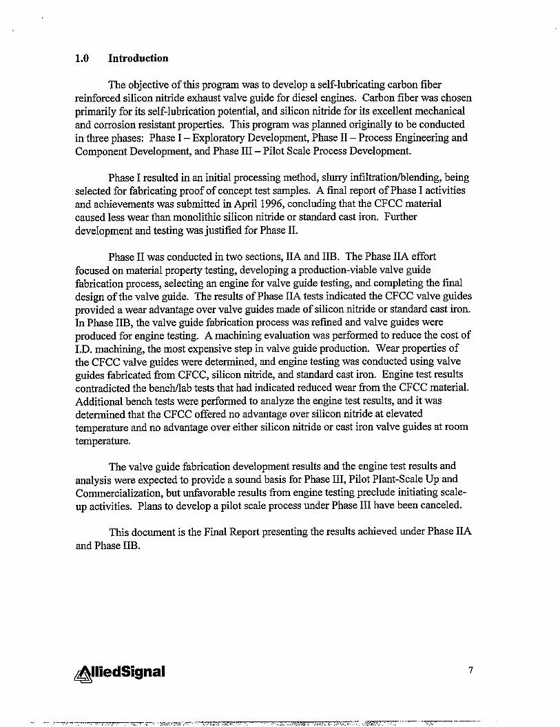
1.0 Introduction
The objective of this program was to develop a self-lubricating carbon fiberreinforced silicon nitride exhaust valve guide for diesel engines. Carbon fiber was chosenprimarily for its self-lubrication potential, and silicon nitride for its excellent mechanicaland corrosion resistant properties. This program was planned originally to be conductedin three phases: Phase I – Exploratory Development, Phase II – Process Engineering andComponent Development, and Phase III – Pilot Scale Process Development.
Phase I resulted in an initial processing method, slurry ifilltratiodblending, beingselected for fabricating proof of concept test samples. A final report of Phase I activitiesand achievements was submitted in April 1996, concluding that the CFCC materialcaused less wear than monolithic silicon nitride or standard cast iron. Furtherdevelopment and testing was justified for Phase II.
Phase II was conducted in two sections, 11Aand IIB. The Phase 11Aeffortfocused on material property testing, developing a production-viable valve guidefabrication process, selecting an engine for valve guide testing, and completing the finaldesign of the valve guide. The results of Phase 11Atests indicated the CFCC valve guidesprovided a wear advantage over valve guides made of silicon nitride or standard cast iron.In Phase IIB, the valve guide fabrication process was refined and valve guides wereproduced for engine testing. A machining evaluation was petiormed to reduce the cost ofI.D. machining, the most expensive step in valve guide production. Wear properties ofthe CFCC valve guides were determined, and engine testing was conducted using valveguides fabricated from CFCC, silicon nitride, and standard cast iron. Engine test resultscontradicted the bencldlab tests that had indicated reduced wear from the CFCC material.Additional bench tests were performed to analyze the engine test results, and it wasdetermined that the CFCC offered no advantage over silicon nitride at elevatedtemperature and no advantage over either silicon nitride or cast iron valve guides at roomtemperature.
The valve guide fabrication development results and the engine test results andanalysis were expected to provide a sound basis for Phase III, Pilot Plant-Scale Up andCommercialization, but unfavorable results from engine testing preclude initiating scale-up activities. Plans to develop a pilot scale process under Phase III have been canceled.
This document is the Final Report presenting the results achieved under Phase 11Aand Phase IIB.
7&iedSignal
.:=?...;,--.,,--—”..<—--——-.

2.0 Background
The driving forces for diesel and natural gas engine technology are reliability,durability, efficiency, and emission regulations [1]. The foundation of reliability anddurability is common to both the social need for reduced emissions and the customerneed for increased efficiency and reduced owning and operating costs. The exhaust valveguide was identified as a component whose reliability and durability are negativelyimpacted with the increased diesel engine efficiency and the use of low-emission fiels.
Engine efficiency is a primary driving force for engine technology [2]. There areexisting programs to incorporate technology into engine design to increase efficiency andincrease the power output. Since 1980, the usable power from an engine has increasedfrom 36 to 43 percent. These efficiency increases translate into decreased otig andoperating costs in every application using an engine as a power source.
The impact of el%ciency can be shown in the power generation market where anincrease of 2 percent in fiel efficiency can translate into $30,000 to $60,000/year savingsper engine in fuel costs. Market growth is expected in power generation due to theener~ needs of developing countries. Increased efficiency will help the end-user loweroperating costs and when combined with low emission technologies will supplydeveloping countries with cleaner power.
Improved fbel economy is achieved, in part, through insulation of combustionchamber components, thereby reducing heat rejection, along with the incorporation ofexhaust heat recovery systems, such as turbocompound units [2]. The insulatedcomponents include piston caps, flame deck inserts and exhaust port liners. Thistechnology also has the potential for cost effective uses in high load-factor industrial andagricultural applications where operating costs are driven by engine fuel costs.
Valve guide temperature in LHR diesel engines can exceed 650”C compared toless than 250”C in conventionally cooled engines. This is due to higher exhaust gastemperatures (>1200°C vs. 550-650”C) and higher cylinder head temperatures that resultfrom the elimination of watercooling. Cast iron valve guides in current engines operatefor 20,000 hours with commercial liquid lubricants fed into the guide-valve steminterface. At temperatures above about300”C, however, the cast iron has insufficientyield strength to support valve stem side loads. The resultant deformation in the guideallows the valve to contact the cylinder liner and/or not seat properly in the valve seat,resulting in a decrease in the operating life and performance of the engine [3]. Anotherchallenge for valve guides operating at temperatures above 500”C is that the availablelubricants, both commercial and experimental, cannot withstand this severe thermo-oxidative environment without deposit formation and loss of friction and wear control.Excess deposits cause valve sticking and/or form into particles that accelerate abrasivewear of the valve stem and guide.
Federal emission standards enacted in 1991 and 1994 for NOXand particulaterequire attainment of 5 gmmslhp-hr of NOXand 0.1 grardhp-hr of particulate for on-
&liedSignal 8
●

highway diesel engines. One source of particulate emissions is lubrication flowing downthe valve guide and entering the combustion chamber. Incorporation of a self-lubricatedvalve guide would reduce the amount of lubricant in the combustion chamber which, inturn, would reduce the amount of particulate emissions.
Stricter Government environmental regulations are also causing an increase in thenumber of alternative fieled diesel engines. Examples of alternative iiels are methanol(M-85), propane, and compressed natural gas. These fuels are significantly cleanerburning and for this reason, will form fewer deposits during combustion. In diesel fueledengines, the combustion deposits coat a number of the critical tribological interfaces suchas the valve stem and valve guide, and serve as a solid lubricant, reducing wear. Innatural gas fieled engines, these deposits are not present and for this reason there is asignificant amount of wear at the valve stem-valve guide interface. The incorporation ofa self-lubricating CFCC guide in this engine application would reduce the amount ofwear between the valve stem and valve guide because the fiction coefficient between aself-lubricating guide and valve stem would be reduced. Reducing the amount of wearwould increase the time between engine overhauls which, in turn, would reduce theowning and operating costs of a natural gas fueled engine.
Finally, natural gas engines are facing strong competition in Europe wherecompetitors are increasing operating pressure and benefiting from increased efficiency[4]. In order for Caterpillar to surpass the competition and increase market share amongEuropean competitors, engine efficiency (and thus operating pressure) must rise. Thehigher pressure will further increase the high wear conditions for the valve stem-valveguide interface.
In view of the above, the need was identified for a self-lubricating, carbon fiberreinforced silicon nitride valve guide, which would provide both the required fiction andwear properties and structural integrity under all these operating conditions.
The wear behavior of ceramic composites containing carbon is a fimction of thethickness and spread of the carbon lubricant film that is present between the matingsurfaces. In the application under this program, the carbon film would be formed by thesliding action between the carbon containing composite surface and the mating metallicsurface. The thickness of the interracial carbon film is dependent on the carbon loadingin the composite. In composites that have less than a critical amount of carbon, thesliding surface is only partially covered with a carbon film and for this reason thecoefficient of friction is dependent on the composite matrix material and the matingmetallic surface. On the other hand, for composites containing carbon above the criticalamount, the sliding surface is completely covered with the carbon and the coefficient offriction is independent of the materials in the sliding pairs [5, 6].
The wear behavior of carbon containing composites shows that the carbonconsiderably reduces both wear and friction. In addition, the transition from light tosevere wear occurs at significantly higher contact pressures [7]. Incorporation of a CFCC
@liedSignal 9
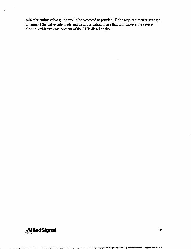
self-lubricating valve guide would be expected to provide: 1) the required matrix strengthto support the valve side loads and 2) a lubricating phase that will survive the severethermal oxidative environment of the LHR diesel engine.
@liedSignal 10

3.0 Phase IIA/B Technical Progress
3.1 Introduction
The objectives of Phase IIA/B were to determine the effect of using self-lubricating exhaust valve guides in a current production natural gas fieled diesel enginewith valve guide problems, and to develop a cost effective near-net-shape formingprocess to fabricate valve guides. The technical efforts reported here from Phase HA/Bencompassed Task 3.2 Process Engineering, Task 3.3 Component Fabrication andTesting, and Task 3.4 Component Evaluation.
3.2 Process Optimization for Manufacturing (Task 3.2)
The objective was to establish a cost effective near net-shape forming process tofabricate CFCC valve guides. Two near-net-shape forming techniques were investigatedin parallel at the start of Phase 11A: Cold isostatic pressing (CIP) and gelcasting. Thetwo techniques were applied under Task 3.2.1 and were to be evaluated under Task 3.2.2.However, prior to the Task 3.2.2 evaluation, CIP was down-selected as the most cost-effective process to produce CFCC valve guides meeting the performance, dimensionaland stiace finish specifications. The CIP process for forming valve guides wasoptimized under Phase IIB Task 3.2.1.
3.2.1 Net Shape Fabrication Optimization
3.2.1.1 Cold Isostatic Pressing
The objective of this effort, to develop a cold isostatic pressing (CIP) techniquefor forming CFCC valve guides, was met under Phase IIA/B. The CIP technique wasselected due to its high potential to be a low cost, high speed process to fabricatecylindrical parts, such as valve guides. Prior to this program, CIP technology had beendeveloped at CC for the purpose of fabricating monolithic GS-44 parts, including varioussized tubular parts.
The key to successful fabrication of a ceramic part by CIP is control of the feedstock powder’s flow characteristics. The feed stock powder is usually prepared by a well-controlled spray drying process, such as that developed at AlliedSignal Inc., CeramicComponents for monolithic GS-44 silicon nitride. The fiber and GS-44 raw materialscould not be spray dried together to prepare CFCC feed stock powder, so a blendingprocess for the fibers and GS-44 spray dried powder was developed. To prepare for theblending operation, the fibers had to be separated into individual fibers (1/8” long) fromthe as-received fiber tows, without damaging the fiber integrity. Several experimentaltechniques were evaluated. Of these, a wet process, which involved mixing/agitation and
@iedSignal 11

screening, was the fmit technique to achieve complete fiber separation and effective fiberlength control. The wet processed fibers were dried and blended at 10 VOIYOloading withstandard spray-dried GS-44 powder.
The effectiveness of the blending operation was evaluated by examining themicrostructure of press powder feedstock. Disks (1.125 “ dia.) were pressed from theCFCC mix using a uniaxial die. A microscopic examination of the as-pressed surfacesshowed that the fibers were separated and uniformly distributed. Using the sameblending parameters to prepare feedstock powder, two tubes (approximately 7“ long x0.75” O.D x 0.22” I.D.) were successfully formed by dry bag CIP. The pressed disks andtubes were successfully densified by hot isostatic pressing (HIP) to fidl density (using thethermal processing procedure established under Phase I).
However, process refinements were needed. The wet agitation process for fiberseparation and sizing, while effective, was time consuming, labor intensive, and produceda low yield (approximately 70Yo)of fiber. A dry agitation process was developed,producing fiber separation and length reduction results better than the wet process, in lesstime and higher yield (approximately 90%). Batches of CFCC feed stock were preparedand CIPed, resulting in tubes with smoother and straighter O.D. surfaces. A microscopicexamination of the fractured surface, which represents the interior structure, showed thatfiber agglomerates were present and the fiber length was still too long.
After five iterations of processing optimization experiments from fiber separationthrough HIP densification, a “baseline” process was defined which produced dense tubeshaving uniform fiber distribution. While yield was lower than desired due to crackingduring pressing and warpage during densification, the baseline process did produce finalmachined specimens within specifications. The process was applicable for tubescontaining both 10°/0and 12.5°/0by volume of chopped carbon fiber. This baselineprocess was used to fabricate the test specimens and prototype valve guides for enginetests under Task 3.3 Component Fabrication and Testing. A flowchart of the valve guidefabrication process is shown in Figure 3.2.1.1-1. Views of the CFCC’S isopressed andsintered microstructure are shown on the flowchart.
12

CFCC Valve Guide FabricationProcess
I
I 104523-2A[
Figure 3.2.1.1-1. The baseline CFCC valve guide fabrication process is shown. Amicrograph of blended material is shown on the upper right, and the microstructure ofHIPed CFCC material is shown on the lower left.
@iedSignal 13

Having established the baseline process, refinement efforts continued under thistask in parallel with preparations for engine testing under Task 3.3. Several experimentswere conducted to reduce the raw material cost by substituting lower cost fiber, but theresults were poor. An alternative method of reducing material cost was to minimize theexcess material needed for grind stock. This was accomplished by improving the fiberseparation, batch mixing, and pressing processes, thereby reducing significantly theamount of warpage in the densified tubes. The reduction in warpage with processimprovements is illustrated in Figure 3.2.1.1-2. The tube at the left shows atypicalsintered tube from the baseline fabrication process. The middle tube illustrates thereduction in warpage after the improvements, and the tube on the right illustrates thereduction in grind stock (the tube was pressed in smaller diameter CIP tooling)accomplished by the improved fabrication processes.
Figure 3.2.1.1-2. Improvements to the baseline fabrication process significantly reducedthe amount of grind stock required on the CFCC valve guide blank.
14#t#iedSignal
... .,>.,.—.,..,—, v-k,7?,.>%7..‘.:<..:.!,.-.s..,, -.,,~%~f~+------- ~ ----

While warpage was significantly improved, yield remained unacceptable due toincidence of warpage and, more significantly, cracking of the tubes. These issues wereaddressed successfully toward the end of this task. In the meantime, the issue of processscale-up was investigated as described in the following paragraphs.
Experiments were pedormed to determine whether the CFCC tubes could beformed using a higher volume, production-ready technique. The wet bag CIP used in thebaseline process involves filling a flexible mold (bag) with the CFCC powder mixture,immersing the bag in a fluid tank, and pressurizing the fluid to compact the powdermixture. The wet bag CIP process is desirable for small quantities of components,because tooling is inexpensive and easy to make. However, wet bag CIPing is not idealfor high volume production, as it is a labor intensive, batch process. The “dry bag” CIPtechnique offers the potential for automated, high volume production. Powdercompaction is accomplished by aidfluid pressure at five times the rate of the wet bagprocess. Dry bag CIP processing requires less hands-on labor. Blanks are formed, oneafter the other, as long as powder is supplied to the press. Another advantage is that tubescompacted with the dry bag are uniformly dense along their entire length, resulting in lesswasted material at the ends of the compacted piece.
The most significant unknown in switching to the dry bag process was its effecton the CFCC’s microstructure. As an initial evaluation, existing wet bag CIP tooling wasmodified to fit the dry bag press and CFCC tubes were CIPed. The tubes were densified,sectioned, polished and examined under an optical microscope. There was no apparentdifference in microstructure compared to wet bag CIPed CFCC tubes; the fibers wererandomly oriented and uniformly dispersed. These results, from experiments usingmodified tooling, indicate that the CFCC tube forming process could be successfullytransitioned to the dry bag process and optimized for high volume production.
Alternative thermal processing techniques also could improve productionreadiness and reduce processing costs. In the baseline process, tubes are densified by hotisostatic pressing (HIP). While the HIP process is highly effective, it is a batch process,relatively expensive and with no potential for automation. Gas pressure sintering wasidentified as a potential lower cost alternative. However, initial experiments producedpoor results. CFCC tubes were gas-pressure sintered in the thermal cycles normally usedto densi@ monolithic GS-44 silicon nitride. None of the CFCC tubes reached fbllsintered density in the gas pressure sintering experiments, and the carbon fibers werebadly deteriorated. Further sintering experiments would be needed to determine whethera gas pressure densification cycle could be developed for the CFCC material.
As mentioned above, cracking and warpage were the chief defects causing lowyields from the baseline process. In order to optimize the baseline process, anexperimental matrix was designed, focusing on the first steps of the process: materialsbatching and blank forming. The experimental matrix, designed to isolate the effects ofcritical variables in those process steps.
@iedSignal 15

The matrix was designed to test the effects of 1) raw material lot-to-lot variations,2) blended material lot-to-lot variations (GS-44 silicon nitride powder blended with 10volOAAmoco P-75 chopped carbon fibers), 3) mold type (size of bag, core rod material,and core rod length), and 4) packing density of the powder before pressing. The resultsof the test matrix suggested that the incidence of cracking and warpage correlated only tofactors 3 and 4 (mold type and packing density), while little or no effect was shown fromfactors 1 and 2 (lot variations from raw materials or blended materials).
The test matrix results indicated a 100% correlation between cracking and a gapbetween the core rod and the bag cap. Also, cracks occur when the core rod material isnot sui%ciently stiff. Both of those factors were eliminated. Consistently good resultswere achieved with hardened steel core rods of sufficient length so that no gap waspossible between the rod and the bag cap. The primary cause of warpage was correlatedto low packing density in the mold. Being controlled by the mold filling procedure, thisfactor was also eliminated. Sufficient packing density of the powder mix can be achievedby tapping the mold as it is filled, as demonstrated in the experimental results. Warpingoccurred in tubes that were not tapped while the mold was being filled, but none of thetubes warped that were tapped during filling.
In summary, a baseline process for fabricating CFCC tubes was established andoptimized during the execution of this task. The primary factors were identified whichcontrol warpage of the CIPed tubes and yields from the process. The process was revisedaccordingly, resulting in significant improvements. The potential for automating theforming process by dry bag CIPing was indicated by preliminary pressing experiments.Further experimentation would be required to develop an effective gas pressuredensification cycle that could replace the baseline glass encapsulation HIP process.
3.2.1.2 Gel Casting
The objective of this effort was to develop a near-net shape forming technique forfabrication of valve guides using gelcasting. The potential advantages of this techniqueover conventional slip casting, which was used in Phase I material development, includethe use of more production-oriented, all-metal reusable tooling, shorter casting time, andmore uniform microstructure and better dimensional control.
A baseline gelcasting technology was developed for monolithic GS-44 (underother development programs at CC) for various near-net shape components, includingtubular parts. The approach for forming CFCC tubes was first to prepare the baselinemonolithic GS-44 slurry with gelling agents and then blend the fibers into it to form ahomogeneous composite slurry before adding the gelling initiators. However, none of thefirst attempts to gelcast CFCC material produced a homogeneous composite casting.
It became apparent that the CFCC slip/slurry preparation procedure for gelcastingprocess would need significant development work to produce a uniform distribution of
&iedSignal 16

the carbon fiber. Meanwhile, very good results from the CIP process effort wereachieved. The work on developing a gelcast CFCC material was therefore discontinued.
3.2.2 Evaluation
This effort was to evaluate CFCC specimens fabricated under Task 3.2.1 Near-Net-Shape Fabrication Optimization using either dry bag cold isostatic pressing (CIP) orgelcasting. Wear coefficients were to be generated using the Cameron-Plint reciprocatingfriction and wear test machine. The operating conditions for this friction and wear testing(temperature, loads, and lubrication) were to be determined by Caterpillar. The wearspecimen geometries were to be an AISI 4140 valve stem running against a quartersection of the silicon nitride – carbon fiber composite exhaust valve guide. Finally, thedata and processing were going to be analyzed and used to select between the twofabrication processes for fiuther optimization under Phase IIB. The CIP process wasselected so no process down-selection based on friction coefficient was needed.
3.3 Component Fabrication and Testing (Task 3.3)
3.3.1 Specimen and Prototype Valve Guide Fabrication
3.3.1.1 Property Specimens
The objective of this effort was to fabricate CFCC plates (at the two selected fiberloadings), using the Phase I process (pressure slip casting), for machining into test barsfor characterization under Task 3.3.3 Mechanical Property. The required number ofplates (2” x 3” size) were fabricated through HIP densification at CC, and shipped toCaterpillar for machining and characterization.
However, due to the very good CIP results discussed in Task 3.2.1, it was decidednot to proceed with machining and characterization of the slip cast specimens. To betterrepresent the properties of the prototype valve guides, the test specimens were machinedfrom CIPed tubes. Two tubes of 10% by volume P-75 fiber in GS-44, two tubes of12.5% by volume P-75 fiber in GS-44, and one tube of monolithic GS-44 were shipped toCaterpillar for machining and testing, which was conducted under Task 3.3.3.
@iedSignal 17
- ,= -77AT7-.. .. .. .. . ,,,,...,. _. ._. _ ..,

3.3.1.2 Prototype Valve Guides
The original work plan for this task was to use the process developed under PhaseI (pressure slip casting) to fabricate prototype valve guides for durability testing underTask 3.3.4 in a simulated diesel engine test rig. For comparison purposes, the test planincluded valve guides of baseline cast iron, monolithic GS-44, and the two CFCCcompositions selected under Phase I. Two large CFCC plates (approximately 5“ x 5“ x1.2”) were slip cast, fi-omwhich tubes would have been machined. However, the workplan was revised following the promising results from Task 3.2.1. With approval fromthe DOE Program Manager, the fabrication method was changed to CIP. The prototypeCFCC valve guides were machined instead from tubes fabricated by the baseline processdescribed in Task 3.2.1.
For bench testing, twelve tubes, four with no carbon fiber, four with 10% byvolume of carbon fiber, and four with 12.5% by volume of carbon fiber, were CIPed,partially densified (presintered), presinter machined, fully densified (sintered in the hotisostatic press), and final machined leaving 0.45mm grind stock on the ID. The tubeswere shipped to Caterpillar for bench tests described in Tasks 3.3.2,3.3.3, and 3.3.4.Caterpillar pefiormed the final grinding operation on the valve guides’ I.D. per thedrawing specifications. Vitreous bonded diamond grinding wheels were used for the I.D.final grinding, according to the procedure developed under Phase I.
For engine testing in the 3500 series natural gas-fueled engine, fifty-six tubes,twenty with no carbon fiber and thirty-six with 10% by volume of carbon fiber, wereprepared as described in the previous paragraph by the baseline process. Examples of theguides, containing 10% carbon fiber, are shown in Figure 3.3.1.2-1. Again, Caterpillarfinal machined the I.D. to the final dimensions and surface finish prior to installing theguides in the test engine under Task 3.4.3. Also fabricated and shipped to Caterpillarwere twelve valve guides with 10°/0carbon fiber for a model 3126 diesel-fieled enginetest. The 3126 engine test was not conducted, as explained in Task 3.4.1 EngineSelection.
&iedSignal 18
-- ,.——...--.,-~,, --- J ? .~ -;~+”: .; ,%,>-:4.,.,-.:---., ...,. ,.,...;.? ..>,”.. -+ + : .,.’,:~\?,+;,:<,,,.- ;. ,::+--- —=-----— -*. .-:..’.h .

Figure 3.3.1.2-1. Examples are shown of the CFCC valve guides fabricated under Task3.3.1.2. The guides were final ground on the I.D. and engine tested under Task 3.4.4.1 atCaterpillar.
3.3.2 Wear Coefficient
Caterpillar was to generate up to six average wear coel%cients for AISI 4140(Rc50) valve stems running against quarter sections cut from two of the prototype carbonfiber reinforced silicon nitride valve guides for Task 3.4.2 Final Design. In addition,Caterpillar was to generate average wear coefficients for the currently used 3516 S.1.engine series valve stem and guide material pairs, using the procedures outlined in Task3.2.2. These average wear coefficients were to be used to benchmark the current exhaustvalve guide operating pefiormance in this application. Upon completion of this testing,this wear data was to be analyzed to determine if the prototype CFCC exhaust valveguides meet all the tribological petiormance criteria.
The original specimens received from AlliedSignal had a bore diameter of 9.Ommas called out on the print. However, the I.D. grinding of the bores of the CFCC valveguide blanks took more time than originally expected because the creep-feed grindingtechniques developed in Phase I could not be used due the large stock removal. The92rnm bore length required special quills to be designed and fabricated. These quillsrequired that the forces during grinding be kept low to prevent the quills from deflectingduring the grinding. Deflection of the quills during grinding would cause excessive taperin the I.D. dimension and very high grinding wheel wear. For this reason, new I.D.grinding techniques had to be developed to reduce the grinding forces. These new
@liedSignal 19

techniques used smaller depth of cuts, which significantly increased the time required tomachine the bores.
Therefore, the amount of stock remaining on the bores was reduced. No morethat 0.05mm of stock should be removed from the I.D. during this operation (Note --some machining of the I.D. is required to obtain the required tribological properties).
The modified valve guide specimens were machined and several changes made tothe Carneron-Plint test fixture. Testing was then completed for valve guide specimensconsisting of monolithic silicon nitride and silicon nitride plus 10 volume percent carbonfiber (no tests were run on cast iron guides). Tests were run against valve stem sections(4140, chrome coated stems). Figure 3.3.2-1 shows the test specimen and fixture with theconditions listed in Table 3.3.2-1.
Figure 3.3.2-1. Valve Stem (left) and Guide Section (in fixture, right) used in theCarneron-Plint Test
20

Table 3.3.2-1. Cameron-Plint Test Conditions
Temperature 120° cLubrication: 1. Dry (with small amount of oil added
prior to the test simulating oil presentduring engine assembly)
2. LubricatedLoad 20N (approx. 20X operating conditionsCycles 1.44E06 (8 hours)@, 50Hz
The wear on each valve stem was determined by measuring the wear scar using3-D surface tracing techniques. Wear on the valve guides was not reported due to thechipping that occurred on the guide edges where the stem impacted during testing. Theresults of this testing are contained in Table 3.3.2-2.
Table 3.3.2-2. Cameron-Plint Friction and Wear Test Results
Valve Guide LubricantCompositionCFCC/10’Xo Lubricatedcarbon fiberCFCC/10% Non-lubricatedcarbon fiberMonolithic Lubricated
Silicon nitrideMonolithic Non-lubricated
Silicon nitride
Average FrictionCoefficient
0.12
0.1
0.12
0.16
None measurable None measurable
4.5E-08 None measurable
7.78E-07 None measurable
I I
The results showed that no measurable valve stem wear occurred irrespective ofthe valve guide composition (monolithic silicon nitride or CFCC) or lubrication condition(lubricated or non-lubricated). However, the average friction coefficient and valve guidewear for the non-lubricated CFCC was slightly lower than that of the non-lubricatedmonolithic silicon nitride. The lower fiction coefficient and valve guide wear factor ofthe CFCC should result in greater durability in non-lubricated conditions.
3.3.3 Mechanical Property
GS-44 silicon nitride as-densified tube specimens containing O, 10, and 12.5volume percent P-75 graphite fiber were supplied by AlliedSignal for mechanical testing.These specimens were machined into Military Std. 1942z “B” sized modulus of rupturespecimens for 4-point flexure testing. The results of this testing are contained in Table3.3.3-1.
#!&iedSignaI 21

Table 3.3.3-1: Mechanical Properties of GS-44 Silicon Nitride Densified Tubescontaining various amounts of Amoco P-75 Carbon Fibers
Fiber Number of Avg. Flexural Flexural Elastic WeibullLoading Specimens Strength Strength Modulus Modulus
(Volume %) (Mpa) Range (Gpa)(Mpa)
o 20 784 708-826 272 3110 34 282 231-312 230 17
12.5 30 253 206-307 206 12
The results listed in Table 3.3.3-1 showed that the addition of the carbon fibers tothe GS-44 silicon nitride reduced the average flexural strength from 784 to 282 or 253MPa for the 10 and 12.5 percent volume loadings, respectively (Approximately a 64 and68 percent decrease in strength). In addition, the Wiebull modulus for these specimensdecreased from 31 to below 20.
Scanning electron microscope analyses of the fracture surfaces of the specimensafter the flexural testing showed several 50-1OOpmcarbon fiber agglomerates. Examplesof the fiber agglomerates are shown in Figures 3.3.3-1 and 3.3.3-2.

Figure 3.3.3-1. Silicon Nitide with 10 volume percent Carbon Fiber–231 MPa breaking stress;SEM MOR bar fracture surfaces at lOOxand 500x.
&iedSignal 23

Figure 3.3.3-2. Silicon Nitride with 12.5 volume percent Carbon Fiber – 234 MPa breaking stress;SEM MOR bar fracture surfaces at lOOxand 500x.
24

3.3.4 Durability Test
3.3.4.1 Baseline Test
The objective of this task was to determine the durability of the CFCC materialsystem developed under Phase I. The durability testing was performed on a diesel enginevalve sternhalve guide test jointly developed by Caterpillar and Battelle. The bench testis illustrated in Figure 3.3.4.1-1. In general, the test consisted of a single 3500 SeriesEngine cylinder head with valve train. The cylinder head was mounted to a machine baseand an electric motor and flywheel used to rotate the camshaft to operate the valves. Inaddition, upper and lower enclosures were used to confine the diesel exhaust environmentand drip-fed lubricant. Caterpillar provided all the standard production parts to build thetest fixture including ahead group assembly, four push rods and lifters, camshaft, valvebridge, inlet and exhaust valve rockers, rocker shaft, valve cover, and spacer between thevalve cover and cylinder head. A heater was installed in place of a fiel injector and thecylinder head filled with a heat conducting fluid. A temperature of 135°C (270”F) wasmaintained during the tests.
The test plan’s first objective was to determine whether measurable wear could bedetected running production hardware (cast iron guides) in the bench test. Once thisbaseline was established, different confQurations of GS-44 silicon nitride and CFCCguides were run in various lubrication conditions.
25

/
To ExhaustHood
.—II.—./ \ K Upper Cover// \
\Camshaft Timing Gear
iI Camshaft
J f 1
1
II ~ Flywheel
y~ ,
I [-, d II\,~ !—z———————
Lower Cover
Timing Chain o
Heated Diesel Exhaust Inlet
Motor
Crank Timing Gear‘i
1 1 )
Figure 3.3.4.1-1. Battelle Durability Test – Motorized 3500 Series Cylinder Head.
To establish the baseline, a 100 hour test was run using cast iron guides withlubrication. The valve guide bores and stem diameters were measured in three locations(relative to the guide) before and afler testing: at the center, and at 7mm from the top andbottom. All inner diameter measurements were the average of two readings made 180degrees apart with a 3-shoe bore micrometer. Stem diameters were made in similarmanner with a micrometer. Measurement accuracy was reported to be Mpm. The resultsof the 100 hour baseline, listed in Table 3.3.4.1-1, show that measurable wear wasdetectable within 100 hours of testing.
Measurable wear was detected in the short hour baseline test. However, thegreatest valve guide wear typically occurs at the bottom of the guide. In this case, the
##iedSignal 26

greatest wear was consistently near the top. It should also be noted in hindsight thatstandard valve guide wear is measured 12.5mm from top and bottom. This will bediscussed later with the engine test results. Lastly, the bench test was run at a uniformtemperature, with no temperature differential between the guide and stem as in the realengine application that would change the clearance between the guide and stem fromdifferential expansion. Again, this is discussed fhrther with the engine test results.
Table 3.3.4.1-1. Valve Guide and Stem Wear from 100 hour Baseline Durability Test.
Valve Number Location Valve Guide ID
Wear (pm)1 7mm from top 21.2
Center 6.97mm from bottom 14.8
2 7mm from top 25.7Center 9.3
7mm from bottom 14.33 7mm from top 32.3
Center 12.87rnm from bottom 3.9
4 7mm from top 19.2Center 9.8
7mm from bottom 9.7
Valve Stem OD
Wear (pm)8018003535888
Averages 7mrn from top 24.6 5.3Center 9.7 2.8
7mm from bottom 10.7 8.5
3.3.4.2 Lubricated Durability Tests
Following the baseline test, guides for Test 1 were selected consisting of theproduction cast iron, monolithic silicon nitride (GS-44), CFCC with 10 volume percentcarbon fibers (CFCC/1 O)and CFCC with 12.5 volume percent carbon fibers(CFCC/12.5). Caterpillar provided a procedure for press fitting the guides into thecylinder head. Wear measurements were taken at 100 and 200 hours of testing. The castiron guide demonstrated similar wear to the prior baseline test and the cast iron wear washigher than that of any other guide. The stem wear for the GS-44 was the highest,however, the CFCC exhibited no stem wear.
No increase in guide or stem wear was seen in the second 100 hours of testing.This indicates that a 100 hour break-on period may exist for all the guide materials. Withthe minimal wear in the GS-44 and CFCC guides, they may not have “broken-in” during
&liedSignal 27

this test. After the initial break-in, no additional wear occurred within the test. The 100and 200 hour measurement results of Test 1 are shown in Table 3.3.4.2-1.
Table 3.3.4.2-1. Valve Guide and Stem Wear after 100 and 200 hoursof Durability Test 1 (Lubricated).
Valve GuideMaterial
Cast Iron
GS-44
GS-44
CFCC/12.5 percentCarbon Fibers
T(pm)
7mm from top 38.0Center 18.5
7mm from bottom 17.57rnm from top 4.5
Center 0.07mm from bottom 7.5
7mm from top 7.0Center 6.5
7mm horn bottom 0.07mm from top 4.0
Center 8.07mm from bottom 0.0
Guide ID:200 hour
Wear
(~m)37.017.017.52.50.02.56.02.02.05.04.01.5
Stem OD:100 hour
Wear
(pm)5.1----
6.47.6----
2.58.9----
1.30.0
0.0
Stem OD:100 hour
Wear
(pm)5.1----
6.46.3----
1.37.6----
1.32.5----
0.0
A second durability test (Test 2) was conducted using a cast iron, two CFCC/10and a CFCC/12.5 guide, under lubricated conditions. The results were similar to Test 1 inthat the cast iron guides wore the most. The CFCC/12.5 and GS-44 guides exhibitedslightly more wear in this second lubricated test. However, there was essentially nodifference in stem wear between all the guide materials, regardless of the carbon fibers.Also, there was no additional wear in the second 100 hours of test. Table 3.3.4.2-2 showsthe 100 and 200 hour wear data for Test 2.
@liedSignal 28
—. —-:>--7,,- ,=.,,,.,.. .,,,... ,. . + .,~<-~.~T?: .+.+..Z :?.{,.... ..Y- F., -- ...-.>~J,w :1;2-..,&,. -:...,: ‘-.; ~.z’.-m ,.. ,’. .+.. --— - -

Table 3.3.4.2-2. Valve Guide and Stem Wear after 100 and 200 hoursof Durability Test 2 (Lubricated).
Valve Guide Location Guide ID: Guide ID: Stem C)D: Stem OD:Material 100 hour 200 hour 100 hour 100 hour
Wear Wear Wear Wear
(pm) (pm) (pm) (~m)Cast Iron 7mm from top 26.0 26.0 3.2 3.8
Center 10.5 10.5 ---- ----7mm from bottom 16.5 17.5 2.5 2.5
GS-44 7mm from top 3.0 3.5 1.9 2.5Center 3.0 5.0 ---- ----
7mm from bottom 12.5 8.0 1.3 1.3GS-44 7mm from top 6.0 5.0 0.0 0.0
Center 6.0 3.0 ---- ----7mm from bottom 5.0 5.0 1.9 1.9
CFCC/12.5 percent 7mm from top 6.3 2.5 1.9 1.9Carbon Fibers Center 3.0 0.0 ---- ----
7mm from bottom 11.5 9.5 1.3 1.3
3.3.4.3 Restricted Lubrication Durability Tests
The Battelle bench test was modified to restrict lubrication of the valve guide andstem to evaluate the fill benefit of the carbon fibers in reducing wear. This wasaccomplished by the use of a rubber “umbrella” valve stem seal placed on the top of thevalve guide. Approximately 3000 ml of oil leaked past the guides during the lubricated200 hour tests without the valve stem seals. Using the rubber “umbrella” stem seals, only400 ml of oil leaked past the valve guide during Test 3 and approximately 1050ml leakedduring Test 4. (Because of the variation in combined leakage between Test 3 and 4, it islikely that there is substantial variation in the leakage between the individual valve stemseals.)
Table 3.3.4.2-3 contains the valve guide and stem wear measurements from thefirst test with restricted lubrication (Test 3). These results show that the cast iron guideexperienced the highest wear. However, after 100 hours, none of the guides showedadditional wear. This is unexpected since the lubrication was restricted and this shouldhave impacted the cast iron wear at the very least. Valve stem wear was not significantlydifferent between any of the guide materials or lubrication conditions.

.
Table 3.3.4.2-3. Valve Guide and Stem Wear after 100 and 200 hours inDurability Test 3 (Restricted Lubrication).
Valve Guide Location Guide ID: Guide ID: Stem OD:Material 100 hour 200 hour 100 hour
Wear (pm) Wear (pm) Wear (pm)Cast Iron 7mm from top 23.0 27.5 5.1
Center 10.0 9.5 ----
7mm from bottomGS-44 7mm from top
Center7mm from bottom
CFCC/10 percent 7mm from topCarbon Fibers Center
7mm from bottomCFCC/12.5 percent 7mm from top
Carbon Fibers Center7mm from bottom
17.5 14.5 1.90.0 0.0 3.8
+-Hi--E6.0 2.0 2.56.0 5.0 5.12.5 3.0 ----
2.5 5.0 3.8
Stem OD:100 hour
Wear (pm)7.0----
3.83.8----
2.57.0----
2.57.0----
5.1
A second test (Test 4) was conducted with restricted lubrication. The valve guideand stem wear measurements from Test 4 are shown in Table 3.3.4.2-4. As mentionedpreviously, 1050ml of oil was collected from this 200 hour test versus the 400rnlcollected from Test 3. The additional oil may have impacted the wear versus Test 3(restricted). However, Test 4 exhibited the lowest cast iron wear of any of the tests –even lower than Tests 1 and 2 where more oil was used.

Table 3.3.4.2-4. Valve Guide and Stem Wear after 20Durability Test 4 (Restricted Lubric
Valve Guide Location Guide ID:Material 200 hour
Wear
(pm)Cast Iron 7mm from top 12.0
Center 6.57mrn from bottom 9.5
GS-44 7mm from top 0.0Center 2.0
7mrn from bottom 0.0CFCC/10 percent 7rnm from top 0.0
Carbon Fibers Center 0.57mm from bottom 3.5
CFCC/12.5 percent 7mm from top 0.0Carbon Fibers Center 2.0
7mm from bottom 0.0
Ihours in!tiC)n).
Stem OD:200 hour
Wear
(pm)1.7----
0.61.1
-----
0.61.1
0.22.8----
0.6
3.3.4.4 Durability Test Summary
The significant points fi-omthe Battelle testing are:
1.
2.
3.
4.
5.
Measurable cast iron valve guide wear occurred within 100 hours. This wear is mostlikely break-in wear.No additional guide wear occurred after 100 hours of testing (with a 200 hour testlength) for any of the guide materials or lubrication conditions. Test durations greaterthan 200 hours would be needed to truly evaluate the guide materials in this benchtest.Stem wear is insignificant regardless of test duration (up to 200 hours), guide materialor lubrication condition.Variability exists in lubrication as evidenced by the different amounts of oil collectedfor each test.Wear measurements were taken 7mm from the valve guide ends (and matchinglocation on the valve stem). Standard guide measurements for engine testing aretaken 12.5mm from each end In later sections, it will be shown that the guide IDbecomes bell shaped near each end during “break-in”. By measuring only 7mm fromthe end, only the break-in may have been measured.

Task 3.3.5 Selection of CFCC Valve Guides
CFCC guides with 10 volume percent carbon fibers were selected for additionaltesting. The volume percent was selected to minimize the amount of carbon fiber andcost without impacting the guides functionality since no difference in wear was observedin the Battelle test between 10 and 12.5 percent carbon fibers.
3.4 Component Evaluation (Task 3.4)
3.4.1 Engine Selection
The engine selected for testing was a 3508 Natural Gas Engine. The enginespecifications are listed in Table 3.4.1-1 and a picture of the engine is shown in Figure3.4.1-1. The original engine targeted in the program was a low-heat-rejection (LHR)engine that would operate with valve guide temperatures above approximately 260°C. Atsuch temperatures, oil “cokes” and causes valve sticking. Therefore, a guide would berequired that could operate without oil lubrication, hence, the rationale for using thecarbon fiber for lubrication. Since the LHR engine was not available, the natural gasengine was selected. The engine has a production configuration and would also benefitfrom self-lubricating valve guides, because it lacks the lubrication produced during dieselfhel combustion. However, since the natural gas engine operates at guide temperaturesmuch lower than the LHR engine, the benefit of high-temperature lubrication was notevaluated in this engine test.
A 3600 series engine was also considered for testing. However, the size of thisguide was beyond current processing capabilities at AlliedSignal. A 3126 Series enginewas selected as the second test bed, following successful completion of the 3500 NaturalGas engine test. Guides were produced and machined for this engine. However, theguide design changed with an engine modification during the time the guides wereproduced and the 3500 engine test was conducted. Therefore, these guides could not beengine tested.
Table 3.4.1-1. 3508 Series Natural Gas Engine Specifications
Sueed I 1500 mm. I
Brake Mean Effective Pressure 1240 l$aTiming 24 degrees
Emissions Level 180ppm NOX(TA LUFT or 1.1 g/bhp-hr.)
Guide Temperatures 100 to 150°cValve Head Temperatures Intake 300°C
(approximate) Exhaust 550°C
&lliedSignal 32

Figure 3.4.1-1. 3508 Natural Gas Engine Installed in Test Cell
3.4.2 Final Design
The final valve guide design used for the 3508 engine testing is shown in Figure3.4.2-1. The design is based on the existing cast iron guide, and is press fitted into thecylinder head. The guide inner diameter and stem outer diameter provide a colddiametrical clearance ilom 0.082 to 0.040mrn. The outer guide diameter was press fitinto the cylinder head bore with a press fit ranging up to 0.037mm. Engine test
@liedSignal 33

experience has shown that cast iron guides “close-in” an average of 0.023mm as a resultof the press fit.
Md
‘v’=i”Eg @ 12.!30’-B
.t
l)E0vRi+3
NOTE A* DATUM “B= IS ESTABLISHED BYI ZERO CLEARANCE FITTING PIN
)1 ‘ FULL LENGTH OF GUIDE
21 N6TE G’~”FOR 1E2500B INSPECTION, WIREzDETAIL A = n
*; BRU&i ID OF GUIDE ANO RXNSEWIT!+ FREON
BOTH ENDS 0-
NO SCALE NOTE C* APPLY 1E0221 MANGANESE PHOSPHATECOAT.ZNG -AFTERFXNISHED HACHININ~
Figure 3.4.2-1. Final valve guide geometry
3.4.3 Engine Assembly
Theinnerdiameter surfacefinishand morphology oftwo CFCCguides and onemonolithic silicon nitride guide, allmachined at Caterpillar,were examined. Theexamination consisted offirstevaluating the surface finish ofthemachined bores using3-D surfaceanalysis techniques, followed by optical andscanning electronmicroscopytechniques to evaluate the stu%acemorphology and the effect of the machining on thecarbon fibers. The purpose of this small study was to quantifi the surface condition ofthe CFCC and monolithic valve bores prior to engine testing
The results of the 3-D surface analysis are listed in Table 3.4.3-1. Also includedin Table 3.4.3-1, for comparison, was a 3-D surface analysis of a CFCC bore prior to
@liedSignal 34

machining at Caterpillar. The bores, prior to machining at Caterpillar, had stiaceroughness @a) ranging between 0.664 to 0.668pm. One reason for the high Ra valueswas that there were machining lines present. An optical examination of the bores showedthat no carbon fibers were present on the machined surface. Machining the bores atCaterpillar reduced the average surface roughness @a) to 0.233 or 0.388 ~m. An opticalexamination of these CFCC bores showed that the carbon fibers were not damaged duringmachining. Further, the surface morphology and amount of carbon fiber damage due tomachining did not vary along the length of the machined CFCC bore. The roughness ofthe monolithic silicon nitride bores, after machining at Caterpillar, ranged between 0.040to 0.489 pm.
Table 3.4.3-1. Surface Inspection of Machined Valve Guides
Specimen Location Ra Value (pm)CFCC Blank --as received Top 0.664
Bottom 0.683CFCC Value Guide 1 Top 0.302
Bottom 0.388CFCC Valve Guide 2 Top 0.233
Bottom 0.302Monolithic Silicon Nitride Top 0.489
Bottom 0.46
3.4.4 Engine Tests
The original test plan was to run the engine for 250 hours and then measure thevalve stem and guide wear. Also, valve seat recession was to be measured (excess valveguide to valve stem clearances could cause valve seat wear). If all these measurementswere within Caterpillar’s engine tolerance specifications, the engine was to be run for anadditional 250 hours.
3.4.4.1 Engine Test 1-224 Hours
The first engine test began on July 21, 1997 with the valve guide configurationshown in Figure 3.4.4.1-1. No problems were encountered during installation of theguides.
35

SN (Y CFCC SN CFCCCFCCC1’CFCCC1CFCCCFCC C1 CFCC SN SN C1
&&~ ##
SN CFCCC1 CFCCCFCC CFCC
52,
4
Inboard II 1—1 I P)12
34
CFCC SNCFCC CFCC Cl CFCC SN CI CFCC SNCylinder1 Cylinder 8
SN = Monolithic Silicon Nitride guides
CFCK = CFCC Guides (10 volume Percent Carbon fibers)
CI = Cast iron guides (Baseline)
1,2,3,4 valve positions in cylinder
Figure 3.4.4.1-1. Valve Guide Configuration for Engine Test 1 – 224 Hours
The test engine had accumulated 224 hours before a facility problem caused theengine to shut down. During the shut down, cylinder head covers were removed and theCFCC valve guides were examined. This examination revealed that 10 of the 16 CFCCand 1 of the 8 monolithic silicon nitride guides moved during the test. Seven of theCFCC guides that moved were pushed out between 10 to 11 mm. The remaining 3CFCC guides were pushed into the cylinder head. The one monolithic silicon nitridevalve guide was pushed out.
Inspection of the guide OD and cylinder bore ID revealed that the ceramic guideswere machined to print and the cast iron guides were typically oversized. The cylinderhead bores IDs were typically oversized up to 0.2mm, resulting in the valve guidemovement. Guides that remained stationary had cold press fits ranging from 0.004 to0.006mm.
The measurement results for guide and stem wear from the 224 hour test are listedin Tables 3.4.4.1-1 and 3.4.4.1-2. Only guides that did not move were included in thecalculations. The results show that the cast iron guides and mating stems did not wearduring the test. Conversely, the CFCC/12.5 guides and mating stems wore the greatest,in particular on the bottom exhaust position. The GS-44 guides and mating stems woremore than the cast iron, but about half that of the CFCC/12.5. The GS-44 wear was alsogreater on the bottom exhaust guides and stems.
36
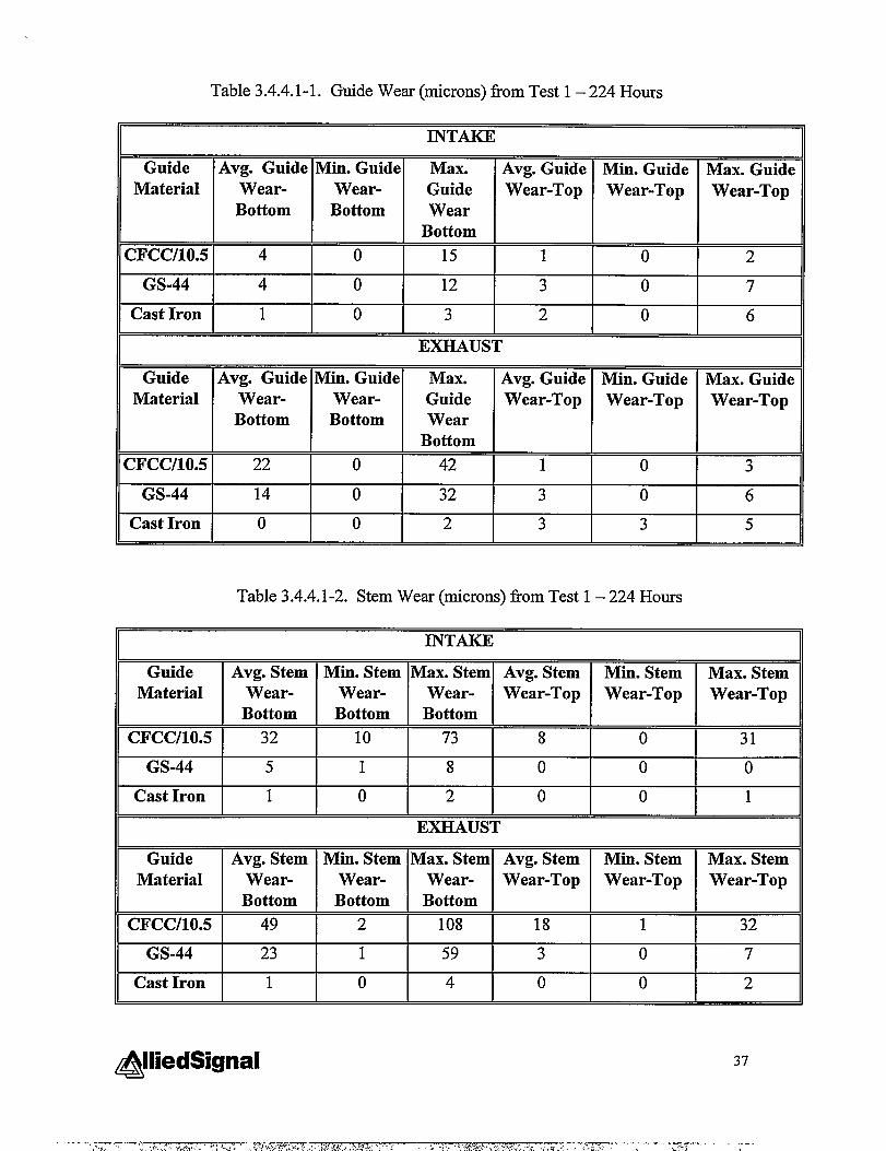
Table 3.4.4.1-1. Guide Wear (microns) horn Test 1 – 224 Hours
INTAKE
Guide Avg. Guide Min. Guide Max. Avg. Guide Min. Guide Max. GuideMaterial Wear- Wear- Guide Wear-Top Wear-Top Wear-Top
Bottom Bottom WearBottom
CFCCI1O.5 4 0 15 1 0 2
GS-44 4 0 12 3 0 7
Cast Iron 1 0 3 2 0 6
EXHAUST
Guide Avg. Guide Min. Guide Max. Avg. Guide Min. Guide Max. GuideMaterial Wear- Wear- Guide Wear-Top Wear-Top Wear-Top
Bottom Bottom WearBottom
CFCCI1O.5 22 0 42 1 0 3
GS-44 14 0 32 3 0 6
Cast Iron o 0 2 3 3 5
Table 3.4.4.1-2. Stem Wear (microns) from Test 1 – 224 Hours
INTAKE
Guide Avg. Stem Min. Stem Max. Stem Avg. Stem Min. Stem Max. StemMaterial Wear- Wear- Wear- Wear-Top Wear-Top Wear-Top
Bottom Bottom Bottom
CFCCI1O.5 32 10 73 8 0 31
GS-44 5 1 8 0 0 0
Cast Iron 1 0 2 0 0 1
EXHAUST
Guide Avg. Stem Min. Stem Max. Stem Avg. Stem Min. Stem Max. StemMaterial Wear- Wear- Wear- Wear-Top Wear-Top Wear-Top
Bottom Bottom Bottom
CFCCI1O.5 49 2 108 18 1 32
GS-44 23 1 59 3 0 7
Cast Iron 1 0 4 0 0 2
@liedSignal 37

Task 3.4.4.2 Engine Test 2-528 Hours
1.2.
3.4.
A second engine test was planned for the following reasons:
Several CFCC guides had moved during the first test.There may not have been enough test time to accumulate significant wear in the castiron.The break-in period could be longer for CFCC guides.The wear results were not as expected.
Fifteen unused CFCC and silicon nitride guides, and eight replacement cylinderheads were inspected for the additional 500 hours of testing. All of the cylinder headshad valve guide bores that were the correct dimension. Nine of the guides were notuseable because of undersized outer diameters andlor oversized inner diameters.Therefore, several conforming guides were selected from the first 224 hour test to be usedfor continued engine testing. Three CFCC guides failed during installation and werereplaced with cast iron guides. The final valve guide test configuration is shown inFigure 3.4.4.2-1.
CFCC C!I CFCC C1 CFCCCFCC CI CFCC SN
&#~##@#s$
Cr CFCCc1 CI SN C1 CFCC SN CFCC SN SIQ CFCC CI CFCC CFCC CFCCCylinder 9 Cylinder 16
SIN= Monolithic silicon Nitride guides
CFCC = CFCC Guides (10 volume Percent Carbon fibers)
CI = Cast iron guides (Baseline)
1,2,3,4 valve positions in cylinder
Figure 3.4.4.2-1. Valve Guide Configuration for Engine Test 2 – 528 Hours.
The 500 hour test started running September 22, 1997 with 13 CFCC, 8 siliconnitride, and 11 cast iron guides. Initially, this test was planned to run without lubricationof the valve guides. However, the stem seals used on all guides metered sufficient oildown the valve stem to consider the test filly lubricated. The engine was inspected afterapproximately 4 hours of operation and no guides had moved.
During a planned inspection at approximately 280 hours, one of the CFCC guideshad moved up in cylinder number 3. The entire cylinder head was removed and replacedwith one containing all cast iron guides. This reduced the total number of guides to 7silicon nitride, 12 CFCC, and 13 cast iron. Note that the valve guide bores and guideouter diameters were inspected prior to the engine test. Guide bores were measured infour locations - two at the bore top and bottom. All bores were within print tolerance.Guides were inspected similarly (4 locations on both the inner diameter and outerdiameter) and those within print tolerance were used for the engine test. Therefore, thethermal expansion mismatch between the cast iron cylinder head and CFCC/12.5 guidemay require a greater press fit.
A second cylinder head (number 1) was replaced near the completion of the 500hours to accommodate other in-house testing. The engine was then run to 528 hours with6 of the 8 original cylinder heads. Cylinder heads that completed at least 500 hours wereinspected for guide and stem wear with the results tabulated in Tables 3.4.4.2-1 and3.4.4.2-2. The results of Test 2 were similar to Test 1 in that the CFCC wore the greatest,followed by the GS-44. The wear was primarily at the bottom exhaust positions. Thecast iron guides and mating stems exhibited no wear regardless of location.
39

Table 3.4.4.2-1. Guide Wear (microns) from Test 2 – 528 Hours
Guide Avg. Guide Min. Guide Max. Guide Avg. Guide Min. Guide Max. GuideMaterial Wear- Wear- Wear Wear-Top Wear-Top Wear-Top
Bottom Bottom Bottom
X’cc/lo.5 5 0 29 0 0 0
GS-44 0 0 0 0 0 1
Cast Iron o 0 0 0 0 1
EXHAUST
Guide Avg. Guide Min. Guide Max. Guide Avg. Guide Min. Guide Max. GuideMaterial Wear- Wear- Wear Wear-Top Wear-Top Wear-Top
Bottom Bottom Bottom
X’CCI1O.5 25 0 71 0 0 0
GS-44 8 0 20 0 0 0
Cast Iron 3 0 17 0 0 1
Table 3.4.4.2-2. Stem Wear (microns) from Test 2-528 hours
INTAKE
Guide Avg. Stem Min. Stem Max.Material Wear- Wear- Stem
Bottom Bottom Wear-Bottom
1 I I
cl?cc/lo.5I 27 7 37
*EXHAUST
-
CFCC/10.5 160
GS-44 37
Cast Iron 1
+--l-+Min. Stem Max.
Wear- StemBottom Wear-
Bottom
+--l--%I
0 3
TI
9 5
I
7
Max. StemWear-Top
18 II, 1
4 1 8 I
39 10
+--H-
Max. StemWear-Top
68
21
3
40@iedSignal
.. ...-.-......~.. ,.=-,,.,,,. ,-r,...r.,,, .... ,...... .,..Y... ....%-J...... ..—,.?..-J.=.,—........__,———.-—

3.4.5 Data Analysis/Recommendation
The results from both the 224 and 528 hour tests were consistent in that the CFCCguide and mating stem wore the most. However, no significant wear occurred with thecast iron guide and mating stem. Figures 3.4.5-1 and 3.4.5-2 graphically compare theaverage wear found in the 224 and 528 hour tests.
Intake and Exhaust Guide Wear❑ Test 1:224 hours
■ Test 2:528 hours
CFCC SN CI
Guide Material
CFCC SN CI
Guide Material
Figure 3.4.5-1. Intake and Exhaust Guide Wear for Test 1 and 2.

❑ Test
■ Test
CFCC SN CI
Guide Material
1:224 hours
2:528 hours
I
*
CFCC SN CI
Guide Material
Figure 3.4.5-2. Intake and Exhaust Stem Wear for Test 1 and 2.
Potential compounding reasons for the high CFCC and silicon nitride wear that wereinvestigated were:
1,
2.
3.
Thermal expansion mismatch and stem to guide clearance: The silicon nitride basedguides have a lower coefficient of thermal expansion (CTE) which may result in asmaller clearance between the valve stem and guide at engine operating temperatures.Incorrect guide geometry and material break-in differences: The cast iron may“break-in” at the end of the guides, relieving contact stress with the valve stem.Conversely, the ceramic guides may not “break-in” at the guide ends and may havecaused line contact between the stem and guide resulting in the adverse wear.Material variations within the silicon nitride guides: Material processing may havecaused variability in the material microstructure or carbon fiber distribution whichresulted in adverse wear.
42&liedSignal
-.——..‘~‘r.;,‘ :.+.:.<’‘Y,1.+’,*<’+:,‘..’,:..-:...,:.‘“.X*’GFd-m;w,,.“-..<>:....>... 7-- ,.:.....4.7,=..-.ZW=----~—-- ..-..~.-,,r:-..,+C%+’,L:.-!..-.,:-,,. . . -3-W.,! ,’‘. .-:.?.... -
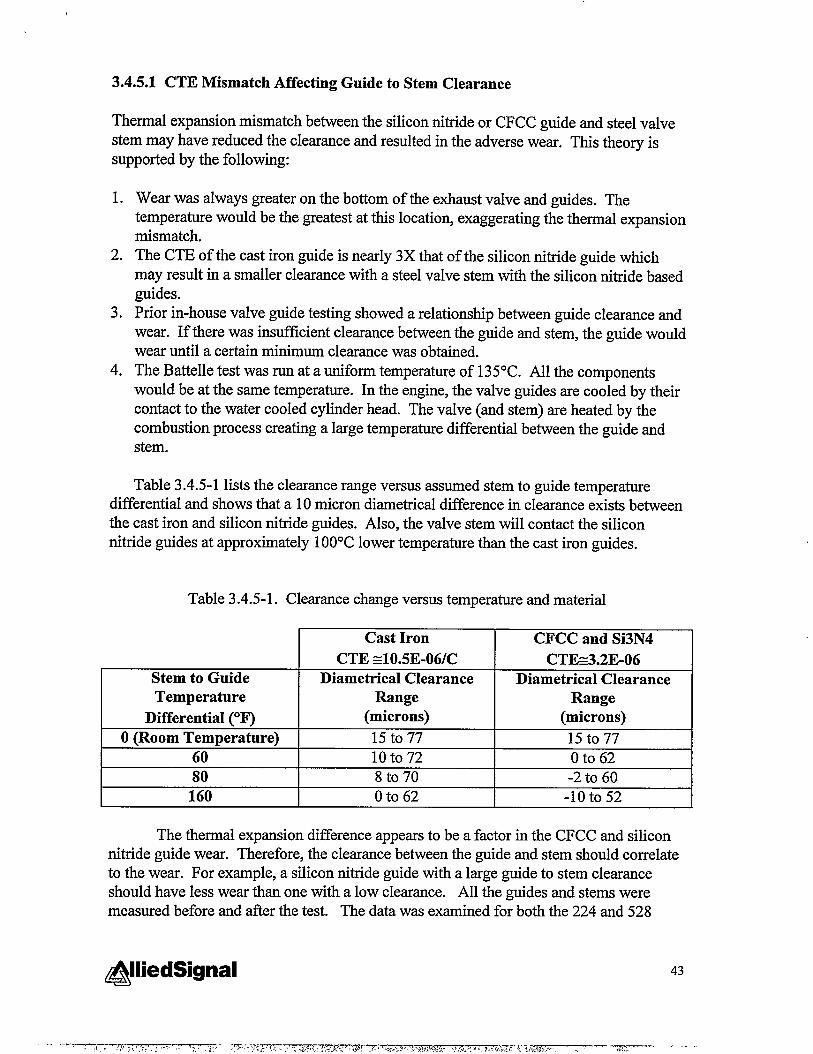
3.4.5.1 CTE Mismatch Affecting Guide to Stem Clearance
Thermal expansion mismatch between the silicon nitride or CFCC guide and steel valvestem may have reduced the clearance and resulted in the adverse wear. This theory issupported by the following:
1.
2.
3.
4.
Wear was always greater on the bottom of the exhaust valve and guides. Thetemperature would be the greatest at this location, exaggerating the thermal expansionmismatch.The CTE of the cast iron guide is nearly 3X that of the silicon nitride guide whichmay result in a smaller clearance with a steel valve stem with the silicon nitride basedguides.Prior in-house valve guide testing showed a relationship between guide clearance andwear. If there was insufilcient clearance between the guide and stem, the guide wouldwear until a certain minimum clearance was obtained.The Battelle test was run at a uniform temperature of 135°C. All the componentswould be at the same temperature. In the engine, the valve guides are cooled by theircontact to the water cooled cylinder head. The valve (and stem) are heated by thecombustion process creating a large temperature differential between the guide andstem.
Table 3.4.5-1 lists the clearance range versus assumed stem to guide temperaturedifferential and shows that a 10 micron diametrical difference in clearance exists betweenthe cast iron and silicon nitride guides. Also, the valve stem will contact the siliconnitride guides at approximately 10O°Clower temperature than the cast iron guides.
Table 3.4.5-1. Clearance change versus temperature and material
Cast Iron CFCC and Si3N4
CTE 40.5E-061C CTE2.2E-06Stem to Guide Diametrical Clearance Diametrical ClearanceTemperature Range Range
Differential (“F) (microns) (microns)
O(Room Temperature) 15t077 15 to 7760- - loto72 Oto 6280 8 to 70 -2 to 60160 0 to 62 -10 to 52
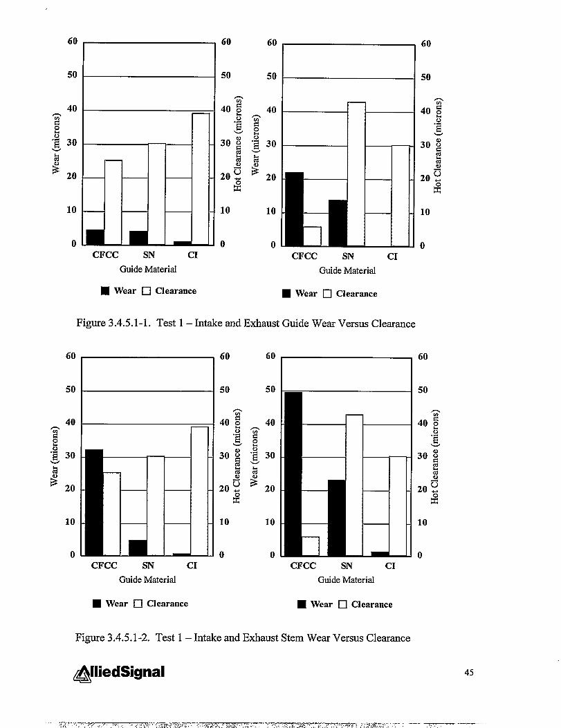
The thermal expansion difference appears to be a factor in the CFCC and siliconnitride guide wear. Therefore, the clearance between the guide and stem should correlateto the wear. For example, a silicon nitride guide with a large guide to stem clearanceshould have less wear than one with a low clearance. All the guides and stems weremeasured before and after the test. The data was examined for both the 224 and 528
&iedSignal 43
.. ...7—.../‘ w :,:.,’’::’:, -. .. ~.. .<., ;.->- ,.,—.7,:.. .. ... . . . .: <.,-JO !-”-, <..-’-. +: .7. J .:,.,-. STWW* .,; . ., Q,:., ., , *.,> ,>,..+ ~ ..--- ~--< ‘y..,< ;,,.. . ,.,...

hour test to see if there was a correlation between operating clearance (calculated fromstarting clearance and assumed temperature differential) and wear. The data from Test 1(the 224 hour test) is compared in Figures 3.4.5.1-1 and 3.4.5.1-2, and the data from Test2 (the 528 hour test) is compared in Figures 3.4.5.1-3 and 3.4.5.1-4.
The 224 hour test seemed to show a correlation between estimated operatingclearance and wear in particular with the CFCC guide which had the smallest clearanceand greatest wear. However, the silicon nitride exhaust guide and mating stem did notfollow the trend. The 528 hour test only showed correlation between clearance and wearat intake locations. Therefore, thermal expansion mismatch may play a role in the CFCCand silicon nitride wear. However, it is only one of the factors and may only play a minorrole.
44
CFCC SN CIGuideMaterial
H Wear ❑ Clearance
CFCC SN CIGuideMaterial
■ Wear ❑ Clearance
Figure 3.4.5.1-1. Test 1 – Intake and Exhaust Guide Wear Versus Clearance
CFCC SN CIGuideMaterial
■ Wear •l Clearauce
—
CFCC SN CIGuideMaterial
■ Wear •l Clearance
Figure 3.4.5.1-2. Test 1 – Intake and Exhaust Stem Wear Versus Clearance

CFCC SN CIGuideMaterial
■ Wear •l Clearance
10
0CFCC SN CI
GuideMaterial
■ Wear ❑ Clearance
Figure 3.4.5.1-3. Test 2 – Intake and Exhaust Guide Wear Versus Clearance
n
CFCC SN CIGuideMaterial
■ Wear ❑ Clearauce
60 200
50160
1040
0 0CFCC SN CI
GuideMaterial
■ Wear ❑ Clearance
Figure 3.4.5.1-4. Test 2 – Intake and Exhaust Stem Wear Versus Clearance
@liedSignal 46

3.4.5.2 Geometry and Material Break-in Differences
The ceramic guides have two to three times the elastic modulus of the cast ironguides. The higher stiffness may prevent or change break-in behavior relative to the castiron. The valve guide inner diameter is machined parallel to the outer dianieter, creatingthe possibility of line contact at the guide top and bottom.
During break-in, the cast iron guides may wear near the bottom, forming a bell-shaped inner diameter so that the line contact or knife edge is blunted. The high stiffnessceramic may maintain the knife edge longer, causing valve stem wear.
The bell-shaped wear that may occur in the cast iron valve guides would not bedetected by the standard guide wear measurements since the measurements are taken12.5m.mfrom either guide end. Therefore, the inner diameter of the valve guides wastraced from end to end using a coordinate measuring machine (CMM). Traces were taken90 degrees apart to give a relative picture of the worn inner diameter profile. The guideswere not in the cylinder head during the inspection.
Initial examination of the 224 hour guides using the CMM method showed adifference in guide geometry between materials as shown in Figure 3.4.5.2-1. Thisillustration of the cast iron guide shows the extent of “banana” shaping of the guide ID.However, there were examples of straighter cast iron IDs. (This shows the variabilitythat exists between guides, even of the same material, that maybe dependent on location,engine assembly, and tolerance stack-up).
47

A
@ ~
---- ---- ---- ____ ___
----- ----- _____ ____
A-A
A
@ ;
----- ----- ----- ----B
----- ----- ----- ----
\
A-A
B-B
Figure 3.4.5.2-1. Inner Diameter (ID) trace of 224 hour CFCC (top) and cast iron guide(bottom).
&lliedSignal 48

Valve guides from the 528 hour test were also inspected using the CMM machineto determine if geometry differences existed between guide materials. The inspectionwas done with the guides installed in the cylinder head to determine if there wereorientation effects on the valve guide wear, i.e. greater wear in the rocker arm axis. Theseinspections showed there were examples of straight IDs as well as curvedhell-shaped IDsfor all guide materials, similar to the 224 hour traces.
The ID traces show geometry but were not used to measure an average innerdiameter. To obtain the actual diameter difference between materials and measurementlocation (bottom versus 12.5mrn from bottom), diameter measurements were taken with adial bore indicator (used for prior wear measurements). An illustration of the twomeasurement locations is shown in Figure 3.4.5.2-2. The results of the measurements arelisted in Table 3.4.5.2-1.
m------------------------------------1A’
IDiameta 2
\
/=
Diameter 1 -
Figure 3.4.5.2-2.
Table 3.4.5.2-1. Inner
Valve Guide Measurement Locations ForDetermining Wear at Guide Bottom
Diameter Measurements of 528 Hour Hardware
Material Location Average Diameter
Difference (pm)
Cast Iron New 10Exhaust 50Intake 16
CFCC New -25I I Exhaust I 2
Intake o
Si3N4 New 5I I Exhaust I 23
I I Intake I o
Number of GuidesMeasured
6
1
22
111
Based on the limited number of guides available for measurement, it appears thatcast iron guides wear more at the bottom than the silicon nitride or CFCC guides (there is
@liedSignal 49

less differential between the measurement locations for both CFCC and silicon nitride).However, from prior tables, the cast iron shows no wear at 12.5mm in from the guideend. Machining procedures were developed that allowed the CFCC and silicon nitridevalve guides to be machined with a tapered inner diameter. Essentially, the deflection ofthe quill provided an acceptable taper, increasing the diameter by approximately 80microns on each end. This procedure could be easily adapted to machining guides and isactually an artifact that has to be carefi,dly removed to make the guide diameter straight.
It should be noted that the CFCC exhaust guides showed an average wear of 25microns at 12.5mm from the bottom. If the CFCC guide IDs became “bell-shaped” earlyin the engine test, they may have worn “straight” during the latter portions of the test. Asimilar possibility exists with the silicon nitride guides which wore an average of 8microns (exhaust location) during the 528 hour test.
3.4.5.3 Material Variation
Material processing may have resulted in variability in the material microstructure orcarbon fiber distributions resulting in adverse wear. To examine this possibility, GS-44and CFCC guides from the 528 hour test were selected. Examples of low and high wearguides were sectioned for qualitative examination in a SEM. Essentially nomicrostructural differences could be seen when examining the center portions of theguide where no wear had occurred. However, there were clear differences between wearlocations within each guide. These differences are illustrated in Figures 3.4.5.3-1 and3.4.5.3-2.
50
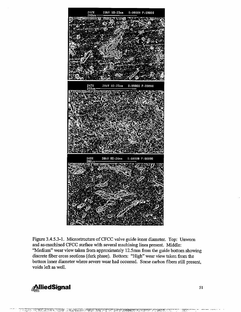
Figure 3.4.5.3-1. Microstructure of CFCC valve guide inner diameter. Top: Unwornand as-machined CFCC surface with several machining lines present. Middle:“Medium” wear view taken from approximately 12.5mm from the guide bottom showingdiscrete fiber cross sections (dark phase). Bottom: “High” wear view taken from thebottom inner diameter where severe wear had occurred. Some carbon fibers still present,voids left as well.
@liedSignaI 51

Figure 3.4.5.3-2. Microstructure of silicon nitride valve guide inner diameter from the528 hour engine test. Top: Unworn and as-machined silicon nitride stiace with severalmachining lines present. Middle: “Medium” wear view taken from approximately12.5mm from the guide bottom showing removal of machining marks. Bottom: “High”wear view taken from the bottom inner diameter where severe wear had occurred. Thehigh wear area appears highly polished.
52

3.4.6 Expanded Bench Testing
The objective of this task was to determine the role and performance of carbonfibers in the CFCC valve guides compared to GS-44 silicon nitride and cast iron incontrolled bench tests. Results of the engine testing were not expected and controlledtests were planned to study the material behavior outside the influence of the engine.Two types of bench tests were conducted under different lubrication, loading, time andgeometry conditions and the resulting friction coefficients and surfaces analyzed. Thesurface examination was conducted to determine if a carbon film forms and if it isconsumed in the duration of test.
The first bench test was conducted at Oak Ridge National Lab (ORNL) using a“ball on flat” conilguration. The second bench test was conducted at Caterpillar usingactual guide and stem sections in a modified Cameron-Plint test.
The ORNL ball on flat bench test was conducted on flat sections of all three valveguide materials. Valve guides (taken from engine tested hardware) were machined intoflat sections with the same stiace finish as the guide inner diameter. A 440C ball wasrun perpendicular to the machining direction at a velocity equivalent to the averageengine valve velocity. Tests were run in both lubricated and unlubricated conditionswith different loads and durations to determine the resulting friction coefficients. Thesurfaces were qualitatively and studied for formation and consumption of the carbon.Wear rates were also determined.
The Caterpillar Cameron-Plint test was modified to accept a valve stem sectionand to slide it back and forth inside a 14mm length of a valve guide (Figure 3.4.5-l).Different loads, lubrication, and temperature conditions were used in the overall testmatrix. Selected surfaces were qualitatively examined.
53

r OIL FLOWLOAD SYSTEM
VALVGUIDE
E
u \\\\\\\\
VALVE5TEM
1--1mm
FIXED
Figure 3.4.6-l. Cweron-Plht Test Fitie Schematic for Holding Valve GtidemdStem
3.4.6.1 ORNL Ball-on-Flat Testing
The following is the executive summary from ORNL’S final report, which is attached inits entirety in Appendix A.
Reciprocating ball-on-flat tests were conducted on prepared sections of cast iron,silicon nitride, and silicon nitride/1 Ovol. 0/0 graphite Chopped Fiber Ceramic Composite(CFCC) valve guides over a range of temperatures, normal loads, speeds, and lubricationconditions. The purpose of this work was to ascertain whether the latter ceramiccomposite would produce a beneficial lubricating film on the valve guide bore surfaceand/or the valve stem. Type 440C stainless steel was used to simulate the valve stemmaterial. Machining practices were selected to provide the surface roughness and lay(direction of grinding marks) similar to that of actual valve guide bores. For comparisonwith the ceramic composite material, both cast iron and silicon nitride matrix materialswere also tested. Tests were also performed using graphite powder on the silicon nitridematrix material to simulate what frictional behavior might be observed in the mostfavorable case.
54

Friction and wear data, combined with stiace chemical analysis confirmed thatthe current composite, while wear resistant, did not provide any lubrication advantagesover silicon nitride itself. No evidence for the sliding-induced formation of a beneficialgraphite film was obtained by optical examination, scanning electron microscopy, orsurface chemical analysis. While the present CFCC did not provide the neededlubricating effect, the results do not preclude the possibility of developing other ceramiccomposites with self-lubricating properties.
3.4.6.2 Caterpillar Cameron-Plint Testing
The objective of this test was to evaluate the valve guide material periiormanceseparately from the design influences discussed in Section 3.4.5 using actual enginecomponents. The two primary design influences discussed were thermal expansionmismatch and break-in differences. These influences were corrected by enlarging theguide inner diameter from 9.502 to 9.602mm and adding a radius at the guide ends. Thelarger diameter should eliminate thermal expansion mismatch to close stem to guideclearance. Adding the radius at the guide ends should prevent severe line contactbetween the stem and guide as the stem slides in and out of the guide.
The test conditions are given in Table 3.4.6.2-1. Pictures of the test fixture andCameron-Plint machine are shown in Figure 3.4.6.2-1.
Table 3.4.6.2-1. Cameron Plint Test Conditions
I Load I 20 N IFrequency 20 HzDuration I 2 hours or 1.5 friction coefficient
Lubrication Dry or LubricatedTemperature 150 C (dry) or 175 C (lubricated)
55

/ Valve(hide
--
~,’ 3“- .~\
‘. > .!k . .;
,. ~ _., , LulnicdngCarri~~e
2. Upper Carriage
3. Lower Carriage 4. Carriage Assembly
Figure 3.4.6.2-1. Carneron-Plint Bench Test
All specimens were inspected for surface finish and dimensional accuracy prior totesting. Lubricated tests were performed f~st and tests were run to completion (2 hours)without difficulty. Friction coefficients for the lubricated test were similar to thosereported by ORNL and are listed in Table 3.4.6.2-2. Figure 3.4.6.2-2 shows the minimalwear scar on the valve stems after the bench tests. No wear scars were evident on theguide IDs, therefore, cross sections were not made.
The tests performed without lubrication resulted in fiction coefficients thatexceeded 1.5 and caused the test to shut down. Examination of the wear scars (shown inFigure 3.4.6.2-3) showed that aligmnent was critical in this test and was not achieved.Several attempts were made to correct the problem since no fiction coefficients had beenreported that went above 1.5. Therefore, the friction coefficients of the dry tests provedinconclusive.
Table 3.4.6.2-2. Friction Coefficient Results for Cameron-Plint Bench Test - Lubricated
~
56@iedSignal
......___-j.,, ,,..:,,.,J.!.A’..:., ..;X->..Irfi.y,z=--‘ —.—-..- .-- ----.-— _....,,>.;,,.,+..,+...,,...-,..,:. .-.73Y>,.-., -,&.,............. ,.?...<,...,, —., .-..

1
A. Cast Iron B. Silicon Nitride
Figure 3.4.6.2-2. Wear Scars on Valve Stem and Guide after Testing - Dry.
p ;;.—- .— ......f.k
A. Cast Iron B. Silicon Nitride1 ‘z
““C. <CFCC ‘ ‘
Figure 3.4.6.2-3. Wear Scars on Valve Stem and Guide after Testing – Lubricated.
@liedSignal 57

4.0 Summary of Phase II Accomplishments
A method to fabricate CFCC valve guides was developed and demonstrated.Initially, two CFCC material formulations (10% and 12.5% by volume carbon fiber) wereevaluated in mechanical property tests. The 10°/0by volume formulation was shown toprovide adequate lubrication. A baseline valve guide fabrication process was developed,using cold isostatic pressing to form the guide blanks and hot isostatic pressing to densi~the guide blanks. Valve guide blanks were fabricated for durability tests in a dieselengine rig. Caterpillar selected a 3500 series engine, using natural gas fhel, for enginetesting. Valve guides (CFCC, silicon nitride, and cast iron) were final machined perCaterpillar specifications and tested in the 3508 engine.
While engine test preparations were made and engine tests were being conducted,refinements were made to the valve guide fabrication process. The refinements increasedthe fabrication process yields and minimized the amount of grind stock to be machinedfrom fully densified valve guide blanks.
The cumulative engine test time exceeded 750 hours. The engine test resultscontradicted the earlier bench and rig test results, in that the wear was higher in CFCCvalve guide/stem pairs from the engine test. The engine test result prompted addhionalbench and rig tests. Caterpillar and Oak Ridge National Laboratory conducted the testsand analyzed the results, concluding that no advantage in wear resistance is provided bythe CFCC valve guide.
Based on the unfavorable results, it is concluded that the work planned for PhaseHI, pilot scale process development, is not warranted.
58

References:
1,
2,
30
4.
5.
6.
7.
Diesel Technology Initiative, 1993.
Heavy Duty Transport Technology Program Plan 1994-1998, Office ofTransportation Technologies, U.S. Department of Energy, Washington D.C.
Kroeger, C. A., Larson, H. J., “Development of Advanced High Temperature In-Cylinder Components and Tribological Systems for Low Heat Rejection Engines -Phase 1 Final Report”, U.S. DOE Contract DEN3-374.
Gas Engines for the 21st Century: A Comprehensive Study of the Outlook For GasEngine Applications Through the Year 2005, Power Systems Research Report.
Biswas, S. K., and Pramila Bai, B. N., Wear, Vol. 68, Page 347 (1981).
Jha A., Prasad, V., and Upadhyaya, G. S. , Wear, Vol. 133, Pages 163 (1989).
Rohatgi, P. K., Ray S., and Liu, Y. Tribology of Composite Materials, Pages 1-6(1990).
@liedSignal 59
—.—-..->.~,-’;+,;, ,-;,7.,+u“%,.T;;,-:.”m ,,,,,,-.*,,.,,, .4.,,!,., , ,, ,.