Embed Size (px)
Citation preview
* #WSRC-TR-98-O0330
DOE Backup Power Working Group Best Practices Handbook forMaintenance and Operation of Engine Generators, Volume II
by
R. E. &oSS
Westinghouse Savannah River Company
Savannah River SiteAiken, South Carolina 29808
K. P. Burrows
A. Padgett
J. Laukea
M. Wong
DOE Contract No. DE-AC09-96SR1 8500
This paper was prepared in connection with work done under the above contract number with the U. S.Department of Energy. By acceptance of this paper, the publisher and/or recipient acknowledges the U. S.Government’s right to retain a nonexclusive, royalty-free license in and to any copyright covering this paper,along with the right to reproduce and to authorize others to reproduce all or part of the copyrighted paper.

-..
DISCLAIMER
TMS report was prepared as an account of work sponsored by an agency of the United StatesGovernment. Neither the United States Government nor any agency thereof, nor any of theirempIoyees, makes any warranty, express or implied, or assumes any legal liability orrespondility for the accuracy, completeness, or usefulness of any information, apparatus,product, or process disclosed, or represents that its use would not infringe privately ownedrights. Reference herein to any specific commercial product, process, or service by trade name,trademark manufacturer, or otherwise does not necessarily constitute or imply its endorsement,recommendation, or favoring by the United States Government or any agency thereof. Theviews and opinions of authors expressed herein do not necessarily state or reflect those of theUnited States Government or any agency thereof.
This report has been reproduced directly from the best available copy.
AvailabIe to DOE and DOE contractors from the Office of Scientific and Technical Information,P. O. Box 62, Oak Ridge, TN 37831; prices available from (423) 576-8401.
Available to the public from the National Technical Information Service, U. S. Department ofCommerce, 5285 Port Royal Road, Springfield, VA 22161.

DISCLAIMER
Portions of this document may be illegiblein electronic image products. Images areproduced from the best available originaldocument.
WSRC-TR-98-O0330Revision O
DOE BACKUP POWER WORKING GROUP
BEST PRACTICES HANDBOOK FOR MAINTENANCEAND OPERATION OF ENGINE GENERATORS,VOLUME II (U)
Westinghouse Savannah River CompanySavannah River SiteAiken, SC 29808
Prepared for the U.S. Department of Energy under Contraqt No. DE-AC09-96SR1 8500
WSRC-TR-98-O0330Revision O
DOE BACKUP POWER WORKING GROUP
BEST PRACTICES HANDBOOK FOR MAINTENANCEAND OPERATION OF ENGINE GENERATORS,VOLUME II (U)
Westinghouse Savannah River CompanySavannah River SiteAiken, SC 29808
Prepared for the U.S. Department of Energy under Contract No. DE-AC09-96SR1 8500
WSRC-TR-98-O0330Revision O
*,.
FORWARD
Chapters in this handbook are intended to supplement original equipment manufacturer(OEM) information and practices primarily for stationary gasoline and diesel engines. Theguidelines presented in the following chapters are based on available literature and theexperience of the Engine Generator Subcommittee members. Hopefully, this andsubsequent volumes will promote consistent best practices throughout the DOE complexin meeting the requirements contained in DOE-STD-3003-94, DOE Standard BackupPower Sources for DOE Facilities.
This document is suitable for voluntary use by engineers and technicians responsible forBackup Power Sources at DOE facilities.
Beneficial comments, including additions, deletions or corrections are encouraged andmay be forwarded to the BPWG through Mr. John Fredlund, DP-45 GTN, U.S.Department of Energy, Germantown, MD 20874-1290; (301) 903-3059, FAX (301) 903-8754.
This document is unclassified.
.*
WSRC-TR-98-O0330Revision O
ACKNOWLEDGMENTS
From 1996 to the present date, the Engine Generator Subcommittee of the Backup PowerWorking Group has drafted, edited and compiled the chapter(s) contained in this volume.Members represent Maintenance, Operation and Engineering disciplines from most U.S.Department of Energy (DOE) sites.
Members who participated in draft, review and edit sessions include:
Gary Borba, DOE-SRJohn Goodrich, LANLAl Martinez, LANLBob Henderson, INELHoward Mason, RFETSJack Goldenberg, SRSAlvin Padgett, SRSKen Burrows, SRSKen Hoopingarner, PNLKarl Frazier, DOE-SRJug Uppal, ANL-EJim Ross, SAICLarry L. Davis, LMITCOJohn Iaukea, SRSKen Freiberg, EASIKeith Martin, RFETSRoger Barklund, LMITCOBill Clapp, INELJorge Alva, WIPPMing Wong, SRSJeff Baver, MoundPhil Hartung, DOE-RFJohn Fredlund, DP-45Robert Gross, SRS / chairman
WSRC-TR-98-O0330Revison O
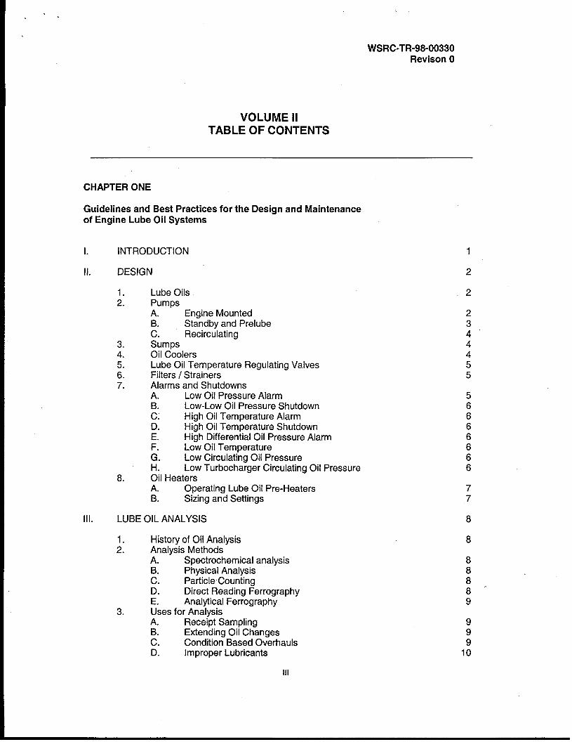
VOLUME IITABLE OF CONTENTS
CHAPTER ONE
Guidelines and Best Practices for the Design and Maintenanceof Engine Lube Oil Systems
1. INTRODUCTION
Il. DESIGN
1
2
1.2.
3.4.!5.6.7.
8.
Lube OilsPumpsA. Engine Mounted
Standby and Prelube:. RecirculatingSumpsOil CoolersLube Oil Temperature Regulating ValvesFilters / StrainersAlarms and ShutdownsA. Low Oil Pressure AlarmB. Low-Low Oil Pressure Shutdownc: High Oil Temperature AlarmD. High Oil Temperature ShutdownE. High Differential Oil Pressure Alarm
Low Oil Temperature& Low Circulating Oil PressureH. Low Turbocharger Circulating Oil PressureOil HeatersA. Operating Lube Oil Pre-HeatersB. Sizing and Settings
2
234“4455
56666666
77
!11. LUBE OIL ANALYSIS
1. History of Oil Analysis2. Analysis Methods
A. Spectrochemical analysisPhysical Analysis
:. Particle CountingD. Direct Reading FerrographyE. Analytical Ferrography
3. Uses for AnalysisA. Receipt Sampling
Extending Oil Changes:. Condition Based OverhaulsD. Improper Lubricants
8
8
8888“9
999
10
Ill

.
WSRC-TR-98-O0330Revison O
Iv.
v.
“ V1.
V1l.
Vlll.
lx.
4. Analysis Criteria5. Sampling Frequency Guidelines6. Sampling – When, Where and How
A. When to SampleSample Points
E Taking a Sample7. The Sample Process8. A Basic Oil Analysis Program9. Estimated Cost of Oil analysis
TYPES OF OILS
1. Petroleum Oil vs. Synthetic Oil2. Multi-viscosity Oil3. Zinc-Free Oil4. Engine Oil Additives
RECOMMENDED OIL GRADES
DISPOSITION OF USED OILS
FLUSHING OIL SYSTEMS
PRESERVATIVE OILS
REFERENCES
101111121212121314
15
15151516
17
18
19
20
21
iv
DOE BACKUP POWER WORKING GROUPBEST PRACTICES HANDBOOK FOR MAINTENANCEAND OPERATION OF ENGINE GENERATORS, VOLUME II
CHAPTER 1
Lubricating Oil Systems
1. INTRODUCTION
The lubricating oil system provides a means to introduce a lubricant in the form of a film to reduce
friction and wear between surfaces that bear against each other as they move.1 The oil filmwhich is established also cools the parts by carrying generated heat away from hot surfaces,cleans and carries dirt or metal wear particles to the filter media, and helps seal the piston to thecylinder during combustion. Most systems are pressure lubricated and distribute oil underpressure to bearings, gears, and power assemblies. Lubricating oil usually reaches main,connecting rod, and camshaft bearings through drilled passages in the cylinder block andcrankshaft or through piping and common manifolds.
Many parts rely on oil for cooling, so if the lube oil system fails to perform its function the enginewill overheat. Metal to metal surfaces not separated by a thin film of oil rapidly build up frictionalheat. As the metals reach their melting point, they tend to weld together in spots or streaks. Lubeoil system failures can cause significant damage to an engine in a short period of time. Propermaintenance and operation of the lubricating oil system is essential if your engine is to accomplishits mission.

.-.
DOE BACKUP POWER WORKING GROUP WSRC-TR-98-00330BEST PRACTICES HANDBOOK FOR REVISION OMAINTENANCE AND OPERATION OF ENGINE GENERATORS, VOLUME 1[
II. DESIGN
The lube oil system of a modern diesel or gas engine includes the lubricating oil itself, oil sump(either on or off engine), oil pumps, internal passages through the block, external piping, valves,filters and filter banks, strainers, coolers, pressure regulators, instruments, alarms and shutdowndevices.
1. Lubricating Oils
Three general types of lube oils are used today. Straight mineral oils which are producedentirely from natural “petroleum” base, synthetic oils which are derived from hydrocarbons,esters, glycols or silicones and finally “additive” oils which are petroleum oils having enhancedproperties. Those properties include slower oxidation, better corrosion inhibition, increased filmstrength, greater solid particle suspension, high viscosity, lower pour point and increased frictionand wear properties.2 Straight mineral oils should not be used as lubricants, with some rareexceptions, due to their poor lubricating properties and very short service life.
Viscosity is probably the most important lube oil property. It is a measure of resistance to flow.A thick oil has high viscosity while a thin oil has low viscosity. Generally, the higher viscosity oilhas better ability to maintain the fluid film between wearing surfaces even when pressedtogether with great force. Viscosity is greatly affected by temperature in that the viscosity dropsdrastically as the temperature increases. Viscosity Index (Vi) is a measure of how viscositychanges with temperature. Viscosity improvers are used to keep the rate of change of viscosityto a minimum from low to high temperature. Synthetic oils and multi-viscosity oils which containVI additives are discussed in more detail later in this chapter.
2. Pumps
A. Engine Mounted
Lubricating oil pumps for engines are positive-displacement type and may be driven by the engineitself or by an electric motor. Changes in engine speed cause corresponding changes in pumpoutput. Pumps usually provide 30-70 psig or even more header pressure, depending on theparticular engine design. Enough flow capacity is provided by lube oil pumps for full load and idleconditions, and sufficient to provide adequate flow and pressure when bearing clearancesincrease. The positive displacement pump will always have a relief valve or relief mechanism toprevent damage from high pressures as when cold oil is pumped during start/warm-up period.
Flow rate through the engine is usually selected so that the rise in oil temperature across theengine, that is between oil entering the engine and that leaving is approximately 25°- 40”F. Manyengines today can operate with an oil outlet temperature as high as 250 “F under rated load but oilusually kept near the same temperature as the iacket water outlet. It is desirable to maintain topoil an-d water temperatures the same to m~nimize thermal distortion.temperature, the greater the oil film thickness will be. 3
B. Standby and Pre-lube
Standby and pre-lube pumps are available for both large and small engines.
The lower the 6il
Standby pumps, alsocalled auxilia~ pumps, may be used as added insura~ce if the engin~ pump capability is” lost forsome reason. A standby pump taking suction on the engine sump will continue to provide oilpressure to the engine. Larger, more costly, or critical applications should consider installing thestandby pump for reliability. Pre-lubricating pumps can be hand operated, or electric motoroperated. They are used to pump sump oil into the main gallery, main bearings, connecting rod
2
c .
DOE BACKUP POWER WORKING GROUP WSRC-TR-98-O0330BEST PRACTICES HANDBOOK FOR REVISION OMAINTENANCE AND OPERATION OF ENGINE GENERATORS, VOLUME Ii
bearings and other critical points to reduce the amount of metal to metal contact and wear duringstartup.
There is controversy over how often and how long to pre-lubricate engines. Interviews withvendors and current vendor literature support from once a week or before each start to once permonth. The amount of time to pre-lubricate depends on how long it takes for oil to reach the valvetrain of the cylinder head. Five minutes on most engines is typical. If the pre-lube period is toolong oil will run down valve guides and accumulate in the combustion chamber. If this occurs, thecylinder may become hydraulically locked as the piston comes to top dead center. Trapped fluidwill prevent the engine from turning and may cause a connecting rod to bend. Pre-lube timeshould be sufficient to only wet the wearing surfaces before the engine is started. The engineshould be primed only until the engine lubricating oil pressure gage registers a slight pressure oruntil oil is seen at each main bearing and the valve train.4 It is best to determine the optimum timefor each engine through actual field experience. Vendors may give rules of thumb, but field dataand direct observation are essential.
With modern high technology oils, the concern for drying of oil films during periods of standby arenot what they once were. Qualitative field testing at one site has indicated that when cylinderliners were maintained in the range 100-150 “F, more than 60 days was required for the oil film to
dissipate.5 Naturally, over that period of time, the film gets thinner but sufficient lubrication isavailable to reduce or eliminate liner scuffing which is a prelude to scoring and permanent cylinderdamage during startup. Consequently, even pre-heated engines maybe started and operated ona 30 day surveillance schedule without damage to cylinders during startup. This assumes theengine is not rapidly loaded. Pre-lubrication is typically used on larger engines whenever they aretest started and on smaller engines that are being started after having been out of service forextended periods.
3
.
DOE BACKUP POWER WORKING GROUP WSRC-TR-98-00330BEST PRACTICES HANDBOOK FOR REVISION OMAINTENANCE AND OPERATION OF ENGINE GENERATORS, VOLUME II
c. Recirculating Pumps
Some recirculating pumps are in continuous operation during shutdown periods. This isespecially true for larger engines and on those engines in a critical start application where therequirement to be started and loaded may be less than 10 seconds. The recirculating oil systemkeeps the main bearing line lubricated with heated oil. This method has been particularly usefulon diesels with aluminum bearings and turbochargers. A more detailed description of the GeneralMotors Electro-Motive Division (EMD) system is explained below.
The EMD system with turbocharger consists of a jacket water immersion heater and two positivedisplacement pumps. One pump is for lubricating the main and connecting rod bearings and theother for lubricating the turbocharger bearing. The immersion heater heats the jacket water andthen circulates it through the oil cooler by thermo-siphon. As the coolant passes through the oilcooler, it heats the lube oil making it easier to pump. The main circulating pump maintains oil inthe external oil system accessories (filter housings, piping, etc.) to prevent oil starvation uponstart-up. The immersion heater is de-energized while the engine is running to prevent damage tothe heater elements.
A dedicated supply of oil to the turbocharger is required due to the vulnerability of theturbocharger bearing to operate with a limited oil supply. Without the turbocharger lubricatingpump, the turbocharger bearing could be damaged due to lack of lube oil upon start-up. Also, thehigh temperature environment in which the turbocharger operates can cause bearing damage ifoil is not supplied to the bearing immediately after shutdown of the engine. The turbochargercontinues to spin for up to a minute after the engine is secured, so a dedicated turbocharger lubeoil pump is provided.
3. Sumps
After oil in an engine has done its lubricating and cooling job, it drops back to an integral orexternal tank commonly known as a wet or dry sump. The wet sump is integral. A dry sumpdesign incorporates a separate oil tank located near to, but not part of, the engine itself. Typicallya pressure pump and scavenger pump are required for dry sumps. Pipe connections to dry sumpsshould enter at or near the top of the tank to minimize spill and fire hazards should a pipe break.Sumps should be large enough to hold the initial charge of oil for theneeded to makeup for that consumed during engine operation. Highalarms, and temperature gages should be installed.
4. Oil Coolers
engine, plus “an amountand low level indicator,
Oil can suffer irreversible damage at extreme temperatures hence the need for heat exchangers.Heat exchangers are used on modern engines to cool below a temperature ‘that wouldpermanently damage the lubricating oil. That temperature is generally recognized as 250°F.Prolonged, sustained oil temperature in this range can break the oil down by oxidation and causecarbon to plate out on sensitive machine surfaces. The lube oil cooler is used to maintain vendorrecommended oil temperatures: Generally, the jacket water is used to cool lube oil, but in somelarger engines, domestic water or salt water maybe used to carry the heat energy away from theengine.
Oil that is too cold can cause problems. The engine works harder to push cold oil through internaloil passages increasing fuel consumption. Just the right temperature and viscosity of oil isneeded to reach into tight bearing clearances and lubricate mating surfaces. Temperatureregulating valves are used on larger engines to maintain proper lube oil temperature. In smallerengines, lube oil temperature is essentially a function of the jacket water temperature regulated bythe water thermostat. Consequently, lubricating oil temperature will follow and be greater than the
4
DOE BACKUP POWER WORKING GROUP WSRC-TR-98-O0330BEST PRACTICES HANDBOOK FOR REVISION OMAINTENANCE AND OPERATION OF ENGINE GENERATORS, VOLUME II
engine jacket water temperature once stabilized at load. The most common lube oil cooler is theshell and tube type. Oil is usually passed through the shell side of the cooler.
5. Lube Oil Temperature Regulating Valves
On some large diesels, regulating valves are used to control the lube oil temperature. Theregulating valve is basically a three way thermostatic valve. It diverts an increasing amount of oilto the lube oil cooler resulting in a decrease in the bulk oil temperature. As the oil temperaturedecreases the amount of oil flowing to the oil cooler diminishes.
6. Filters / Strainers
Paper cartridge type filters or elements are used today in most low and medium speed engines toremove contaminants from the oil. They are usually mounted prior to the cooler so filtering isdone while the oil is hot. Full flow strainers and filters are the general rule, but some olderapplications may be bypass type systems. In the by pass system, a side stream of oil is sent fromthe oil sump through strainer and filter and returned to the sump. Full flow filters ensure that all oilbeing sent to the engine for lubrication and cooling has been filtered. Filtering maybe done using25 micron (0.001 inch) filter media. This filter is capable of removing particles in the oil as smallas 25 microns, but some filters are designed to remove down to 10-15 micron size particles. Filterefficiency is measured by the beta ratio (used to be nominal rating system) and is the ratio of inletparticles versus the number of same size particles in the outlet stream.
Strainers can be single or duplex and are usually mounted on the suction side of pumps to protectpump internals from larger particles. They maybe fitted with magnets to remove metal particles.Duplex filters / strainers are designed to be shifted from one bank or filter to another while theother is being changed or cleaned.
When possible, filter housings should be mounted such that the filters do not drain back to thesump after the engine is shutdown. This can be accomplished by the orientation of the filters andor a check valve. The primary concerns are lack of lubrication to vital engine parts during start-up, and varying sump levels. Shortly after an engine run the sump may be considered too low,and therefore addition of oil at this time may cause an overfull condition when the oil from the filterdrains back to the sump. Filter cartridges with no metal content are recommended because theycan be easier to discard. More information on filter construction, media, centrifuges and purifiersis available.G
7. Alarms and Shutdowns
The application of alarms and shutdowns on diesel lube oil systems varies betweeninstallation and application. The following presents some available options, and is not meant tobe complete list. In some applications the shutdowns are only active when in the manual or testmode. An automatic starl may cause the shutdowns to be bypassed allowing the engine to runeven in the alarm condition.
A. Low Oil Pressure Alarm
This alarm will actuate when oil pressure drops to a level below the normal operating range, butnot low enough to cause engine damage. The purpose of the low oil pressure alarm is to alert theoperator of the condition and to allow time to take action that would prevent further decrease inpressure. This alarm could be an indication of a pump failure either the pressure or scavengingpump, lack of oil supply due to low oil level, or blocked suction strainers.
5
.’.
DOE BACKUP POWER WORKING GROUP WSRC-TR-98-O0330BEST PRACTICES HANDBOOK FOR REVISION OMAINTENANCE AND OPERATION OF ENGINE GENERATORS, VOLUME II
B. Low-Low Oil Pressure Shutdown
This shutdown feature will actuate when oil pressure drops to a level at which engine damage isimminent.
c. High Oil Temperature Alarm
This alarm will actuate when oil temperature is approaching a level above the normal range, butnot high enough to cause engine damage. The purpose is to alert the operator of the condition soaction may be taken to prevent a further increase in oil temperature, or to reduce damage causedby a further increase in oil temperature. This alarm could be an indication of lube oil heatexchanger fouling, low oil level, or oil pump failure.
D. Hi-Hi Oil Temperature Shutdown
This shutdown feature will actuate when oil temperature rises to a level at which engine damageis imminent.
E. High Differential Oil Pressure Alarm
This alarm will actuate when the differential pressure across the lube oil filters approaches a valuewhich could damage the filters, or starve the engine lube oil pump, causing cavitation. The alarmindicates a blockage in the filter. Many filter housings or filters themselves have relief devices thatbypass the filters when the differential pressure becomes too high. This will prevent the damageto the filter and pump, however when bypassing occurs, the oil is no longer being filtered.
F. Low Oil Temperature
This alarm will normally be provided when the diesel generator is equipped with a lube oil heatingsystem for standby operations. The alarm will indicate that the circulation/heating system ismalfunctioning, which could affect the engine start time.
G. Low Circulating Oil Pressure
This alarm will be provided for diesel generator systems equipped with an auxiliary lube oilcirculating pump for pre-lubrication. The alarm indicates a failure of the circulating pump systemor a blockage in the lube oil circulation lines or filters as indicated by low downstream pressure.This alarm may tie into an interlock circuit. The interlock will prevent engine starting if the lube oilpressure is not restored within a certain time period.
H. Low Turbocharger Circulating Oil Pressure
This alarm will be provided for diesel generator systems equipped with an auxiliary lube oilcirculating pump for pre-lubrication of the turbocharger bearing. The alarm could indicate a failureof the circulating pump system or a blockage in the turbocharger lube oil circulation lines or filter.This alarm may tie to an interlock circuit. The interlock will start the auxiliary turbochargerlubricating pump (if provided) and will prevent the engine starting if the lube oil pressure is notrestored within a certain time period.
8. Oil Heaters
Based on the local ambient temperatures, oil heaters are sometimes recommended to eliminatecold and dry starts. Cold oil is very viscous and resists flow. After extended periods betweenengine runs, the oil film between critical engine parts may have dissipated. When the engine is
6
DOE BACKUP POWER WORKING GROUP WSRC-TR-98-O0330BEST PRACTICES HANDBOOK FOR REVISION OMAINTENANCE AND OPERATION OF ENGINE GENERATORS, VOLUME II
started in this condition considerable force is required to fill the critical clearances with oil fastenough to prevent metal to metal contact in the highly loaded areas of the engine. Preheating theoil to the desired temperature reduces its resistance to flow and therefore reduces the timerequired to fill the critical engine clearances. This reduces frictional drag and metal-to-metal wearon start-up.
A. Operating Lube Oil Pre-Heaters
Lube oil preheating systems are similar to engine coolant preheater in that they consist of anelement, thermostat and AC power source. The element is inserted in the oil pan or reservoir anda thermostat is mounted slightly above and to one side of the element to control the temperature.To prevent overheating the oil, the oil heater can be interlocked to de-energize when the dieselstarts. However, this is not necessary as the thermostat has a fairly quick response time and de-energizes the element shortly after start-up of the diesel. The heater element and thermostatshould be located well below the “low” oil level mark on the dipstick. This prevents damaging theelement and properly regulates the bulk temperature of the oil. 7
B. Sizing and Settings
Lube oil heaters are available in numerous voltage settings. For single phase power one mightchoose from 120, 208, 240, 277, 380, 415, 440 and 480, for three phase power there is 208, 240,380, 415, 440, 480, 575 and 600 volts. General purpose, watertight, and explosion resistantenclosures and switches are available. Various temperature settings are available, but typicalranges are from 40 deg. F to 160 deg. F in 20 deg. spans. The lower number specified on thethermostat is the setpoint at which the element is energized, and the higher number is the setpointat which it is de-energized. Sufficient lubrication upon start-up will be provided if the oil’s bulktemperature is about 100 deg. F. Little benefit is gained by heating the oil above this temperature.To minimize operating cost and increase element life a thermostat setting of 80-120 deg, F isrecommended.
Sizing of oil heater elements is based on the sump capacity. A good rule of thumb for mildambient conditions (minimum winter temperatures of approximately O deg. F) is 20-25 watts pergallon. For more severe, arctic conditions, 45 watts per gallon is recommended. To extendelement life and prevent burning the oil, element loading should not exceed 20 watts per squareinch of element surface area. Once this loading is exceeded, more elements or a larger oneshould be used to handle the same capacity. Some sheathed elements are provided to assistwith this problem.
Lube oil heaters improve engine lubrication upon start-up, therefore reducing wear at the mostcritical time in the life of a bearing. Since lube oil heaters do not typically heat the combustionarea of the block, their use alone may not improve cold start reliability. When it is desired to havea quick, reliable, cold start, coolant preheater should be used as they continually warm the blockand combustion area.
DOE BACKUP POWER WORKING GROUP WSRC-TR-98-O0330BEST PRACTICES HANDBOOK FOR REVISION OMAINTENANCE AND OPERATION OF ENGINE GENERATORS, VOLUME II
Ill. LUBE OIL ANALYSIS
There are two purposes for analysis: one, to assess the physical properties of the oil and two, toassess machinery condition. Diesel engine lube oil analysis is the confirmation of engine wear andlubricant breakdown by the detection of increases in the corresponding wear metal content anddecreases in the lubricating properties of the oil. It is a predictive maintenance (PdM) tool to beused in conjunction with other PdM tools such as vibration analysis, inspections, root causeanalysis of failures and a suitable preventive maintenance program. This paper will focus on itsuse in a diesel maintenance program.
1. History
Oil analysis began in the early 1940’s by the railroad industry, as locomotives transitioned fromsteam to diesel power. The Denver, Rio Grande and Western Railway initiated a programwhereby they analyzed the oil of their engines using a spectrograph to detect and measurechemical elements within the oil. The program was successful at identifying the causes of manyof their oil related engine failures, and therefore became widely accepted in the rail industry. By1955 the Navy began experiments with oil analysis on aircraft engines. Their success led theother branches of the military to eventually adopt programs of their own. Since the 1960’s manycommercial industrial operators of equipment have utilized oil analysis as a predictivemaintenance tool.
2. Methods
A. Spectrochemical Analysis
Spectrochemical analysis is the detection and measurement of wear metals (i.e. copper, lead,aluminum, etc.) contaminants (silicon) and additives (calcium, phosphorous, zinc, etc.) in the lubeoil reported and trended in parts per million (ppm) by weight.
B. Physical Analysis
Physical analysis of the oil measures the physical characteristics of the oil such as viscosity, totalacid number (TAN) or total base number (TBN). The analysis can detect contamination of the oilby ethylene glycol, water, fuel, oxidation and combustion products.
c. Particle Counting
Particle counting is the counting of a specific size range of particles in a specific volume of oil.The particle count can then be compared to International Organization for Standardization (ISO)standards for classification of the cleanliness/contamination of the oil. This method isdiscouraged when analyzing diesel engine oils, because the detergent oils used in diesels tendsto turn dark in color fairly quickly in service. The particle counter uses white light to pass throughthe fluid to illuminate and discern the size of the particle. For the counter to “see through” the oil itmust be diluted several times. Dilution increases the margin of error of the test. This method ishowever the preferred method for analyzing hydraulic oils which maintain their clarity in service.
D. Direct Reading Ferrography
Direct Reading (DR) Ferrography is a method of sorting ferrous wear particles magnetically intotwo size ranges (small and large) then measuring the density in each range. This is a fairlyinexpensive test that can be performed each time a spectrochemical and physical test isperformed. A baseline is established and trended. When particle counts increase dramatically,
DOE BACKUP POWER WORKING GROUP WSRC-TR-98-O0330BEST PRACTICES HANDBOOK FOR REVISION OMAINTENANCE AND OPERATION OF ENGINE GENERATORS, VOLUME Ii
Analytical Ferrography should be requested. Direct Reading Ferrography is a screening tool forthe more expensive Analytical Ferrography.
E. Analytical Ferrography
Analytical Ferrography is the visual examination of the wear particles captured on a ferrogram. Aferrogram is nothing more than a highly magnified collage of the wear particles alignedmagnetically. Based on the particle size, shape, color, quantity, and composition it can bedetermined what type of wear metal is being viewed, and the type of wear occurring (abrasive,adhesive, rolling contact, etc.). From this identification, one specific engine component or a list ofcomponents can be identified as providing that wear material, and the engine health can be betterestimated. This tool should only be used after Direct Reading Ferrography has detected apotential problem could exist. The cost of this test is relatively high. Special test equipment isrequired to perform the test. Trained and experienced technicians are required to evaluate theferrogram. It should be noted that analytical ferrography is a another PdM tool that would be usedin conjunction with engine operating history, maintenance history, trending and other preventiveand predictive tools to make maintenance recommendations. Analytical ferrography should not beused as the sole indicator of engine health or justification for engine teardown.
3. Uses for Analysis
A. Receipt Testing
Receipt testing of new oils upon delivery or prior to use is a good practice when the oils are to beused in critical systems. Contamination of new oils with water or dirt is not uncommon due topackaging deficiencies. Containers can breathe due to changes in temperature of the fluid insideif storage drum bunghole plugs are not sealed tight. When the drums breathe, dirt and water canbe ingested into the container. Besides checking for water and contamination, it is important toverify the oil grade and additive package is compatible with the service environment. Physicaltests such as ASTM D1 744 for water, ASTM D445, D4624 or D4683 for viscosity, and visual(clear and bright / no visible particulate) as a minimum should be used to accept new enginelubricating fluids. Viscosity index is another property that can help identify delivery of the wronglubricant.
B. Extending Oil Changes
Oil analysis can be used to extend oil change intervals when the properties of the oil permit it.Many times lubricating oils are changed in equipment based on time-in-use only. This isexpensive and does not provide any useful information as to the health of the equipment or thelubricating oil itself. Lube oil analysis can be used to accurately determine oil condition and toextend replacement until the oil begins to degrade. Extending oil changes provides meaningfulwear particle analysis and lessons the amount of waste generated. Repeatedly changing the oilpotentially masks an engine wear problem because the accumulation of wear metal build-up islost each time the oil is changed.
c. Condition Based Overhauls
Review of wear particle analysis results can be used to help determine if preventive maintenanceand overhaul schedules are too rigid or frequent. Replacing components that are still functioningas designed and show no signs of abnormal or excessive wear is not cost effective. Replacementof components based on time rather than condition also increases the risk of failure due toimproper installation or installation of marginal components. One company estimates that about1/3 of maintenance is performed to correct maintenance-induced problems.
9
.’.
DOE BACKUP POWER WORKING GROUP WSRC-TR-98-O0330BEST PRACTICES HANDBOOK FOR REVISION OMAINTENANCE AND OPERATION OF ENGINE GENERATORS, VOLUME II
D. Improper Lubricants
Qualification of a lubricant can only be measured by actual performance. Mixing different oils isnot recommended because the combination of base stocks and additive packages may not havebeen field tested. The reaction may be unpredictable. Improper lubricant additions and mixingcan be detected through the use of analysis. Changes in the additive concentration levels,viscosity, viscosity index, and other physical criteria will quickly indicate if/when a change in thelubricant make-up has occurred.
4. Analysis Criteria
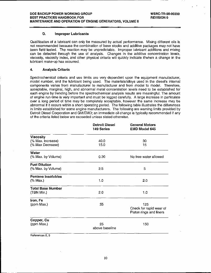
Spectrochemical criteria and use limits are very dependent upon the equipment manufacturer,model number, and the lubricant being used. The materials/alloys used in the diesel’s internalcomponents varies from manufacturer to manufacturer and from model to model. Therefore,acceptable, marginal, high, and abnormal metal concentration levels need to be established foreach engine by trending before the spectrochemical analysis results are meaningful. The amountof engine run-time is very important and must be logged carefully. A large increase in particulateover a long period of time may be completely acceptable, however the same increase may beabnormal if it occurs within a short operating period. The following table illustrates the differencesin limits established for some engine manufacturers. The following are warning limits provided byDetroit Diesel Corporation and GM/EMD; an immediate oil change is typically recommended if anyof the criteria listed below are exceeded unless stated otherwise.
Detroit Diesel General Motors149 Series EMD Model 645
Viscosity(% Max. Increase) 40.0 30(% Max Decrease) 15.0 15
Water(% Max. by Volume) 0.30 No free water allowed
Fuel Dilution(% Max. by Volume) 2.5 5
Pentane Insoluble(’% Max.) 1.0 2.0
Total Base Number(TBN Min.) 2.0 1.0
Iron, Fe(ppm Max.) 35 125
Check for rapid wear ofPiston rings and liners
Copper, Cu(ppm Max.) 25 150
above baseline
References8,9
10
DOE BACKUP POWER WORKING GROUP WSRC-TR-98-O0330BEST PRACTICES HANDBOOK FOR REVISION OMAINTENANCE AND OPERATION OF ENGINE GENERATORS, VOLUME II
Additional resources are available to provide criteria for oil analysis including the equipment
manufacturer, the analysis lab, and the Joint Oil Analysis Program (JOAP).1 O The equipmentmanufacturer typically provides recommendations for oil changes based on time, on the amountof fuel consumed, or on oil analysis results. Minimum values for physical properties, such as TBN,viscosity, contaminant content (EG, fuel, water) fuel soot and total solids build-up are trended. .See the vendor literature listed below for more specific criteria. To the equipment manufacturer,once these levels are reached, the oil no longer provides adequate lubricating properties, andengine wear potentially increases to unacceptable levels. Several engine manufacturers providetheir own lube oil analysis service. Wear particle, spectrochemical and physical test results aretypically compared with the established OEM norms and maximum limits beforerecommendations are provided.
Many oil analysis labs have developed machinery databases involving thousands of pieces ofequipment. Their wear criteria is continually being revised as more data and feedback on aparticular models of engines is gathered. Besides physical test criteria, wear particle analysiscriteria is available. Although criteria is available, it is stressed that the owner review eachanalysis report as a whole before any lab recommendations are accepted. It is very important toevaluate the results of all the tests performed. How they compare to each other and the previousresults is the most significant information. Trends provide meaningful information than a singledata point. Once a reputable, reliable analysis lab has been chosen, it is not recommended tochange labs. Results are generally not comparable from lab to lab so valuable trends maybecome obscured or lost.
The Joint Oil Analysis Program (JOAP) Manual is a comprehensive listing of oil analysistechniques, wear particle analysis limits, severity levels, and recommendations for much of theequipment used in the United States Armed Forces. The criteria is expected to be used in thefield as a consistent, systematic approach to oil analysis. This manual is a Department ofDefense (DOD) document and authorized to be distributed to U.S. Government agencies andtheir subcontractors. More information on oil analysis maybe obtained from References 8 – 12.
5. Sampling Frequency Guidelines
Sampling frequency will depend on oil analysis program objectives and might include extension ofthe oil change interval and evaluation ,of component wear. A typical sampling guideline for anintermittent use diesel is quarterly to semi-annually. For those diesels that run more frequentlyand for longer periods, every 250-500 hours or at the oil change interval whichever occurs first. Ifan oil change i~~being based on oil analysis then more frequent sampling, every 125-250 hours, is
recommended. The most effective program is one that is carefully followed. It is best to confirmthat the samples are being obtained properly and to adjust the sampling frequency as neededbased on recommendations by the analyst.
6. Sampling - When, Where and How
One of the most important parts of an oil analysis program is sampling. Obtaining arepresentative sample of the oil is of utmost importance, as unnecessary maintenance may berecommended based on a “bad sample, and degradation of the equipment and oil may bemissed if the sample is not representative.
11
DOE BACKUP POWER WORKING GROUP WSRC-TR-98-O0330BEST PRACTICES HANDBOOK FOR REVISION OMAINTENANCE AND OPERATION OF ENGINE GENERATORS, VOLUME II
A. When to Sample
Sampling can be performed during the monthly or quarterly diesel surveillance tests as this is themost convenient time. It is best to take a lube oil sample when the equipment is running at itsnormal operating temperature. When that is not possible, drawing the sample within 30 minutesafter the equipment is shutdown may be acceptable. Wear particles tend to settle after only ashort period of time, therefore the longer the wait the more unrepresentative the sample tends tobe.
B. Sample Points
For diesel engines the best location to sample is a sampling valve or petcock installed prior to theoil filter.14 Often times this is not feasible, so the oil dipstick tube or other oil filler tube may beused. Avoid areas where wear particles and contaminants settle out such as oil pan drains, heatexchanger drains and filter bypass lines. The oil pan drain connection would not be desirable forthat reason.
c. Taking the Sample
There are two ways to sample: obtain a pressurized sample from a sampling valve or siphon theoil from the sump. When siphoning, a vacuum pump is used to draw fluid into the samplecontainer or a bellows container draws fluid into the container when compressed and released.Siphoning may also be accomplished using a diptube. Draining is not recommended for reasonsalready stated, however if no other method is possible, then drain enough fluid from the drainvalve to ensure that any contaminants are flushed away before inserting the sample container inthe stream of oil. The above mentioned vacuum pump and associated sample bottle are Navystock items and can be found under the following numbers:
Pump, Oil Sampling NSN 4930-01-119-4030 (Quantity 1)
Bottle, Spectrometric & Physical Test NSN 8125-01-082-9697 (Quantity 120)
7. The Sample Process
A. Draw the sample (approximately 100 cc) from the engine lube oil system asdescribed above, preferably during or just after an engine run.
B. Provide information to the analysis lab: engine manufacturer and model, lube ailsystem capacity, hours on the engine since last overhaul, hours on the oil, APIgrade and manufacturer of the oil, amount of oil added as makeup, and anyadditional comments such as recent problems or maintenance. All of thisinformation is vital to the evaluator of the lube oil analysis results.Recommendations are made based on the results of the test in conjunction withthe information provided. It is difficult to make accurate recommendationswithout all of this pertinent information.
c. Package and ship the sample to the laboratory that provide the analysis.
D. Receive the report from the lab. This may occur in one of several ways: a hardcopy through the mail or facsimile, download of data to an onsite computer viamodem, or updates may be provided on a disk for computer storage andretrieval.
12
. .
. DOE BACKUP POWER WORKING GROUP WSRC-TR-98-O0330BEST PRACTICES HANDBOOK FOR REVISION OMAINTENANCE AND OPERATION OF ENGINE GENERATORS, VOLUME II
E. Notify the lab of any inconsistency in what they recommended versus what wasfound during the corrective maintenance. Also alert them of the actions takenbased on the recommendations. Abnormal results should trigger a re-sample toverify engine and lubricant condition. The responsibility to interpret the report andmake recommendations rests upon the system engineer, maintenance engineeror technkian having custody of the engine. The laboratory can only providerecommendations based on the laboratory results and typically will not be familiarwith the engine’s maintenance or operating history.
8. A Basic Oil Analysis Program
A combination of in-house and outside lab analysis can be cost effective for sites thathave or intend to have a relatively large number of oil samples processed. All samplescan be screened by the in-house analysis and out-of-limit or marginal results can be sentout for a full analysis by the qualified lab. The in-house program should look at basicproperties such as viscosity, viscosity index, water contamination, and ferrous particulate.Some vendors have equipment that will do these tests quickly and at relatively low cost.
A.
B.
c.
D.
E.
F.
G.
H.
1.
J.
K.
Identify and use a reputable and established lab that performs analyses based onASTM standards.
Determine the method of analysis to be performed based on the equipment andits importance: spectrochemical, physical, Direct Reading and/or AnalyticalFerrography.
Develop a sampling procedure based on industry accepted practices. SuggestJOAP or the laboratory analysis vendor literature for guidelines.
Train employees on proper sampling techniques, and the consequences of notsampling properly.
Start small. Focus the analysis on the most important pieces of equipment.
Establish sampling points. Identify either through procedure or on the equipmentby tagging whereto take the sample so consistent results maybe obtained.
Ensure that sample forms are filled out correctly with the pertinent data requiredfor proper identification of the oil and equipment.
Establish mechanism for samples to be analyzed quickly. The sooner thecondition of the oil and equipment is known the better.
Provide a central point of contact for the lab to provide recommendations andcorrect deficiencies (on both sides).
Establish a mechanism to quickly review, confirm and publish recommendationsto the maintenance organization. No one knows the condition of the equipmentbetter than the personnel operating and maintaining it, therefore anyrecommendations from the analysis lab to perform corrective/intrusivemaintenance on the equipment should be reviewed and confirmed by on-sitepersonnel before action is taken.
Confirm that corrective actions have been performed, follow-up samples aretaken, and findings are provided to the lab as feedback.
13
.<.
DOE BACKUP POWER WORKING GROUP WSRC-TR-98-0033(1BEST PRACTICES HANDBOOK FOR REVISION OMAINTENANCE AND OPERATION OF ENGINE GENERATORS, VOLUME II
L. Utilize oil analysis within the existing PM program, along with receipt testing,coolant and fuel analysis, vibration and thermography scanning.
9. Estimated Cost of Oil Analysis
It is not prudent to decrease the amount of sampling based on the cost of the individual samples.Extension of the interval between samples makes it difficult to identify potential problems becauseof the way wear occurs in the engine and how it is detected in the different oil analysis techniques.Small particles (<5 micron) are continually being generated at a steady rate due to normal wear.As abnormal wear occurs the number of large particles (>5 micron) increases in quantity andthere is a subsequent increase in small particles. After a period of time the number of smallparticles decreases back to a normal rate while the large particles continue to be generated.Since the spectrochemical analysis is limited to small particles, an abnormal wear trend maybemissed if used infrequently. Direct Reading Ferrography helps catch the increase in largeparticles generated prior to failure. Analytical Ferrography can be used to confirm an abnormalwear rate and to help determine whether normal or abnormal wear is occurring.
Spectrochemical and Physical $15-$20 per sampleDirect Reading Ferrography $10-$15 per sampleAnalytical Ferrography $50-$75 per sample
Large variance depends upon whetherPhoto-micrographs are provided for each sample
14
.’.
DOE BACKUP POWER WORKING GROUP WSRC-TR-98-O0330BEST PRACTICES HANDBOOK FOR REVISION OMAINTENANCE AND OPERATION OF ENGINE GENERATORS, VOLUME II
Iv. TYPES OF OILS
1. Petroleum Oil vs. Synthetic Oil
Petroleum oil is a lubricant derived from naturally occurring mineral based stock.application of uses and is accepted as the lubricant of choice in diesel engines.
Synthetic oils are man-made lubricants derived from one of the following classessynthesiz~=d hydrocarbons, organic esters, phosphate esters, poly-alkylene
It has a wide
of chemicals:glycols, and
silicones.’= They are typically used when performance demands are beyond petroleum basedlubricant capabilities, such as high and low temperature applications. In recent years their use hasbecome more accepted in typical petroleum product applications due to their ability to reducewear, sludge, corrosion and deposit formations. Synthetic oil apparently does not break down asfast in some applications and therefore lasts longer than petroleum oil. This is extremelybeneficial in systems that are less likely to become contaminated with water or dirt, such ashydraulics, gearboxes, and diaphragm pumps. At this time, the typical cost of synthetic oil isabout 3 times that of the petroleum oil.
Use of synthetic oils in diesels is primarily recommended when operation in extremely coldambient temperatures (approximately <-10 deg. F) will regularly occur. Their use is acceptable tosome engine manufacturers in normal conditions as long as the synthetic oil meets theappropriate API Service categories and grades recommended for the engine. Manufacturers dorecommend that the same oil change interval used for petroleum based lubricants be used forsynthetic oils, therefore it is usually not cost effective to use synthetic oils unless the servicedemands it. This is an ever changing area of lubricant technology. Studies indicate that syntheticoils do not allow proper wear-in or break-in to occur, therefore their use is not recommendedduring the first several hundred hours of engine operation. Before using a synthetic based oil,contact the original equipment manufacturer for recommendations.
2. Multi-Viscosity Oils
Multi-viscosity oils are produced by special refining with the addition of viscosity improvers. They(V1 improvers) provide for easier starting in cold weather yet allow the oil maintain desirableviscosity at elevated temperatures. Some engine manufacturers do not recommend multi-viscosity oils for their diesel engines because the viscosity will vary slightly in engines subjected towide variations in power output and speed. Also, there has been some abnormal engine partwear and high oil consumption attributed to the use of multi-viscosity oils. Shearing of the longchain polymers that exist in multi-viscosity oils can cause unexpected changes in viscosity andlead to engine failure. Typically, an engine vendor or original equipment manufacturer (OEM) willtest a particular engine model with various commercially available lubricating oils. If engine wearand oil consumption data are acceptable to the vendor, the oil will be endorsed. Vendors testwith multi-viscosity and synthetic oils and either publish an endorsement of the oil or make clearstatements not to use those oils. The OEM should be contacted to evaluate the proper oil foreach engine.
3. Zinc-Free Oils
Zinc additive compounds such as zinc dithiophosphate are blended into many lubricating oils, butcan cause severe damage in engines with silver-coated bearings in highly loaded applications.The highly loaded bearings in question tend to wipe during operation once the silver coating isgone. Galvanic corrosion occurs between the zinc compound and silver material. Degradationwill occur when the engine is not running if the circulating lube oil system provides warm oil to the
15
DOE BACKUP POWER WORKING GROUP WSRC-TR-98-O0330BEST PRACTICES HANDBOOK FOR REVISION OMAINTENANCE AND OPERATION OF ENGINE GENERATORS, VOLUME II
bearings in standby. As little as 10 ppm of zinc can be considered excessive and thereforeunacceptable for use with silver bearings. Engine manufacturer’s whose equipment is susceptibleto this degradation suggest using a zinc-free oil. The OEM should be contacted to choose theproper oil for your engine.
4. Engine Oil Additives
Today’s engine oils are made up of a refined base stock and a specific balance of additives tomeet the API Service Classification desired performance characteristics. Use of supplemental,secondary market additives such as friction reducers, teflon derivatives, etc. can upset thebalance of additives formulated into the oil. Additive drop-out can occur, causing sludge build-upand oil filter blockage. Supplemental additives are discouraged by the DOE-BPWG, enginemanufacturer’s, and lubricant producers. Engine damage may result from using these additives.
16
DOE BACKUP POWER WORKING GROUP WSRC-TR-98-O0330BEST PRACTICES HANDBOOK FOR REVISION OMAINTENANCE AND OPERATION OF ENGINE GENERATORS, VOLUME II
v. RECOMMENDED OIL GRADES
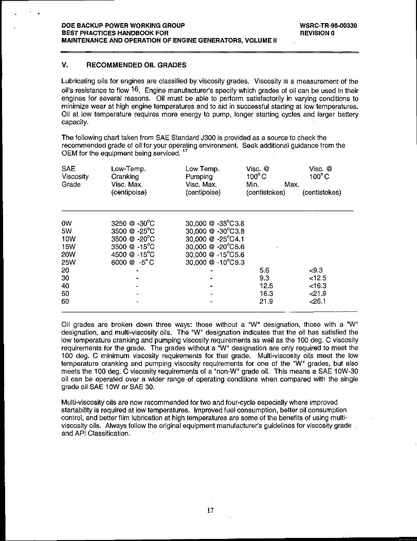
Lubricating oils for engines are classified by viscosity grades. Viscosity is a measurement of the
oil’s resistance to flow 16. Engine manufacturer’s specify which grades of oil can be used in theirengines for several reasons. Oil must be able to perform satisfactorily in varying conditions tominimize wear at high engine temperatures and to aid in successful starting at low temperatures.Oil at low temperature requires more energy to pump, longer starting cycles and larger batterycapacity.
The following chart taken from SAE Standard J300 is provided as a source to check therecommended grade of oil for your operating environment. Seek additional guidance from theOEM for the equipment being serviced. 17
SAE Low-Temp. Low Temp. Vise. @ Vise. @Viscosity Cranking Pumping 100° c 100° cGrade Vise. Max. Vise. Max. Min. Max.
(centipoise) (centipoise) (centistokes) (centistokes)
Ow5W1Ow15W20W25W2030405060
3250 @ -30°C3500 @ -25°C3500 @ -20°c3500 @ -15°C4500 @ -15°c6000 @ -5° C
30,000 @ -35°C3.830,000 @ -30°C3.830,000 @ -25°C4.130,000 @ -20°C5.630,000 @ -15°C5.630,000 @ -lo0c9.3
5.6 <9.39.3 <12.512.5 <16.316.3 <21.921.9 <26.1
Oil grades are broken down three ways: those without a “W” designation, those with a “W”designation, and multi-viscosity oils. The “W” designation indicates that the oil has satisfied thelow temperature cranking and pumping viscosity requirements as well as the 100 deg. C viscosityrequirements for the grade. The grades without a “W” designation are only required to meet the100 deg. C minimum viscosity requirements for that grade. Multi-viscosity oils meet the lowtemperature cranking and pumping viscosity requirements for one of the “W” grades, but alsomeets the 100 deg. C viscosity requirements of a “non-W” grade oil. This means a SAE 10W-30oil can be operated over a wider range of operating conditions when compared with the singlegrade oil SAE 10W or SAE 30.
Multi-viscosity oils are now recommended for two and four-cycle especially where improvedstartability is required at low temperatures. Improved fuel consumption, better oil consumptioncontrol, and better film lubrication at high temperatures are some of the benefits of using multi-viscosity oils. Always follow the original equipment manufacturer’s guidelines for viscosity grade .and API Classification.
17
.’.
DOE BACKUP POWER WORKING GROUP WSRC-TR-98-00330BEST PRACTICES HANDBOOK FOR REVISION OMAINTENANCE AND OPERATION OF ENGINE GENERATORS, VOLUME 1[
w DISPOSITION OF USED OILS
Used oil may be handled by Recycling, Re-refining, and disposal. The first of these are the mostenvironmentally attractive choices.
Recycling is an application where the used oil is filtered to remove contaminants and then usedagain as a lubricant usually in less severe operating conditions, such as a chain lubricant. Onlyone process is generally recognized as being acceptable for diesel engine oil re-refining. Thisprocess is one in which the oil is treated as a crude oil, subjecting it to the same refining processused for geolo ical crude.
12The process involves dehydration, vacuum distillation, and
hydrogenation.
Used lubricating oil may be provided as a fuel source for a co-generation or an incinerator facility.
18
. .
DOE BACKUP POWER WORKING GROUP WSRC-TR-98-O0330BEST PRACTICES HANDBOOK FOR REVISION OMAINTENANCE AND OPERATION OF ENGINE GENERATORS, VOLUME II
VII. FLUSHING OIL SYSTEMS
Flushing is often recommended for larger engines when a major parts failure has occurred, the oilcontains an excessive amount of water or antifreeze deposits, or whenever the engine is beingremoved from storage. Ancillary equipment such as filter housings, heat exchangers, andexternal piping should be cleaned separately to prevent particulate from dropping into low velocityareas.
Most engines can be flushed with the oil grade that would normally be used in the engine.Heating the oil helps break sludge deposits carrying particulate with it through filter bags. Waterin the oil system can be flushed with oil, however kerosene sprays maybe needed to break-up theoil/water emulsion. If ethylene glycol has been introduced into the oil system, sludge and tar-likebuild-up can be found. Therefore, a material other than oil is necessary to adequately flush thesystem. Butyl cellosolve or ethylene glycol monobutyl ether mixed with lubricating oil isrecommended to remove the deposits. The OEM should be consulted when performing a flushusing these materials since the ratio of butyl cellosolve and oil varies from manufacturer tomanufacturer. Contact the DOE BPWG for assistance in obtaining more detailed information onflushing engine lube oil systems.
19
DOE BACKUP POWER WORKING GROUPBEST PRACTICES HANDBOOK FORMAINTENANCE AND OPERATION OF ENGINE GENERATORS, VOLUME II
WSRC-TR-98-O0330REVISION O
VIII. PRESERVATIVE OILS
Preservative oils would be used to replace normal engine fluids if the engine were going to beinactivated for 6 months or more. These preservative oils prevent corrosion better than thenormal service fluids by leaving a thin, non-drying, protective film on the engine internals.Several grades exist within Military Standards MlL-C-l6173 and MIL-L-21 260 to accommodatethe length of time the engine will be inactivated. Generally speaking, the longer the intendedinactive period, the more tenacious the grade of preservative oil required for proper protection. Athorough overview of preservative oil selection, application and removal can be found in NAVSEAHandbook S9086-HB-STM-OOO/CH-233. 19 If sufficient care is taken to secure all openings to theatmosphere when preserving eng,ines, the entrance of dirt, foreign material, and moisture can beprevented. Blank flanges, dark thick plastic bags and specialty tapes that can withstand repeatedtemperature fluctuations and weather conditions should be used. A corrosion resistant metal tagshould be applied to the equipment stating that the engine has been preserved and listing, date,point of contact, the procedure/method/preservatives used and those steps needed for safe returnto service.
20
.*
DOE BACKUP POWER WORKING GROUP WSRC-TR-98-O0330BEST PRACTICES HANDBOOK FOR REVISION OMAINTENANCE AND OPERATION OF ENGINE GENERATORS, VOLUME II
lx.
1.
2.
3.
4.
5.
6.
7.
8.
9.
10.
11.
12.
13.
14.
15.
16.
17.
18.
19.
REFERENCES
U.S. Navy Diesel Engine Inspector Handbook, Part 11,Technical Information,S9233-CJ-HBK-020, Chapter 16, p. 16-1, published by direction of Commander, NavalSea Systems Command
Standard Practices for Low and Medium Speed Stationary Diesel and GasEngines, 6thEdition, p. 94, Diesel Engine Manufacturers Association (DEMA), 1972
P.J. Louzecky, Private Correspondence to DOE BPWG Diesel SubcommitteeChairman, dated June 22, 1993. Not a public document (npd)
NAVEDTRA 10541 -C2, Engineman 3&2
Qualitative Study of General Motors 278A vertical mounted porous chrome platedcylinder liners coated with SAE 30 Wt, REG/RHM - SRS, April 1994 (npd)
Karl W. Stinson ME, Diesel Engineering Handbook, 12th edition,
Bulletin IMC-200, Section 11,p. 19, Kim-Hotstarl Mfg.
Technician’s Guide, Lube Oil Analysis Primer for Diesel Engines,Characteristics/Analysis, Detroit Diesel Allison, 1984
Lubricating Oil for EMD Engines - Marine, Power, and Drilling Rig, MaintenanceInstruction 1760, Rev. G, Electro-Motive Division, General Motors Corporation
Joint Oil Analysis Program (JOAP) Manual, Navair 17-15-50, published by direction ofCommander, Naval Air Systems Command under the authority of the JOAP Regulation,September 1, 1990
Maintenance and Construction Procedure, Testing Used Lubricating Oils, PL24,El. duPont de Nemours & Co., May 1987 (npd)
Oil and Your Engine, Caterpillar Inc., 1990
Instruction Manual, Maintenance Through Analysis, Form AIIM, p. 7, Analysts Inc., 1988
Basics of Oil Analysis, Form 4015, p. 4, Analysts Inc., 1992
Ron Holzhauer, “Guide to Synthetic Lubricants”, Plant Engineering, Volume 48, No. 16,p. 67, Cahners Publishing Co., December 1994
Cummins Engine Oil Recommendations, Cummins Operation and Maintenance -Construction and Industrial Bulletin 3810340, p. 3-2, Cummins Engine Company, Inc.
SAE J300 FEB91, Engine Oil Viscosity Classification, Society of AutomotiveEngineers
Detroit Diesel Engine Requirements - Lubricating Oil, Fuel and Filters, 7SE270 9505, p. 7,Detroit Diesel Corporation
Naval Ships’ Technical Manual, Diesel Engines, S9086-HB-STM-OOO/Chapter 233,published by direction of Commander, Naval Sea Systems Command,
21