Embed Size (px)
Citation preview
DOCUMENTS APPROVED DATE ACTION REV
MN MS -001
BAK ER
BUSHNELL 10/06/07 L AA AA
BAK ER
BUSHNELL 10/06/07 D24165 AB AB AB -001
PRODUCT LINE TOTALFLOW®
LEVEL 3 TOTALFLOW Products
DESIGN DATE REVISION STATUS FOR THIS IS CONFIDENTIAL AND PROPRIETARY SIEVERS 10/06/07
INFORMATION BELONGING TO ABB INC. DRAWN MANUAL, G3 LIQUID ORIFICE APPLICATION GUIDE BAKER 10/06/07 MANUAL CHECKED CAMP 10/06/07 APPROVED SCALE SIZE TYPE DRAWING NO. REV SHEET BUSHNELL 10/06/07 NONE A RS 2012981 AB 1 OF 1
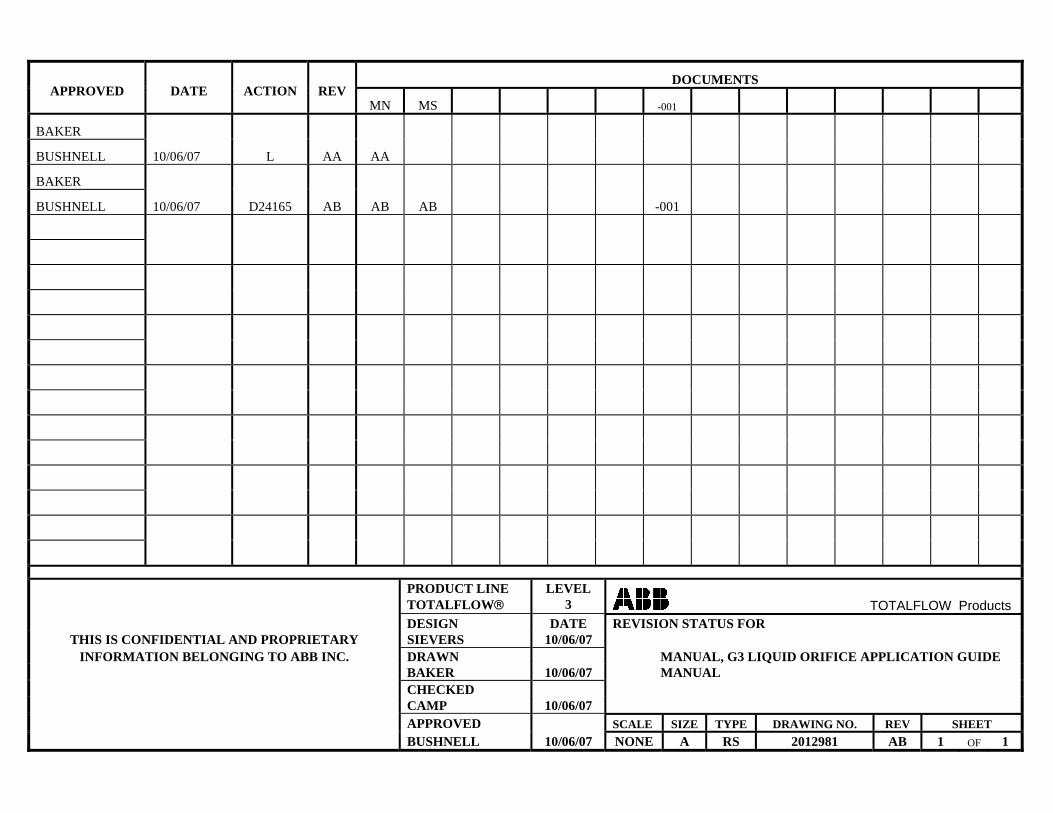
REV ACTION DRAWN CHECKED APPROVED DATE AA L ROBERTS CAMP BUSHNELL 10/06/15 AB D24165 BAKER CAMP BUSHNELL 10/06/21
MANUAL SPECIFICATION
Specification for “MANUAL, G3 LIQUID ORIFICE MEASUREMENT” (2012981-001) Binders:
• Document to be “Twin Loop Wire Spiral Bound (Black) Printing the Front Cover & Back:
• A full color artwork for the front cover (DOUBLE SIDED) and back will be furnished for reproduction. • Reproduce the front and back from the copies provided on a similar weight paper (100# gloss) (double sided) Reproduction can be photographic or any manner to produce a high quality likeness maintaining the same color and screen tints. Printing the Main Body of the Manual
• 20 pages of masters to be become 10 double-sided pages. • Literature to be a high quality black and white reproduction on 28# premium paper. Document Assembly: Document to be assembled in this order: • Clear Overlay • Front Cover (Full color double sided) • Main body of the manual • Back Cover (Full color) • Clear Overlay • All to be bound using black Twin Loop Wire PRODUCT LINE TOTALFLOW®
LEVEL 3 TOTALFLOW Products
DESIGN DATE MANUAL SPECIFICATION FOR B.SIEVERS 10/06/15 DRAWN MANUAL, G3 LIQUID ORIFICE MEASUREMENT BAKER 10/06/15 APPLICATION GUIDE CHECKED MANUAL CAMP 10/06/15 APPROVED SCALE SIZE TYPE DRAWING NO. REV SHEET BUSHNELL 10/06/15 NONE A MS 2012981 AB 1 OF 1

2012981-001– rev. AB
Totalflow® G3 Liquid Orifice Measurement Application Guide
µFLO 6213

Intellectual Property & Copyright Notice
©2010 by ABB Inc., Totalflow (“Owner”), Bartlesville, Oklahoma 74006, U.S.A. All rights reserved.
Any and all derivatives of, including translations thereof, shall remain the sole property of the Owner, regardless of any circumstances.
The original US English version of this manual shall be deemed the only valid version. Translated versions, in any other language, shall be maintained as accurately as possible. Should any discrepancies exist, the US English version will be considered final.
Notice: This publication is for information only. The contents are subject to change without notice and should not be construed as a commitment, representation, warranty, or guarantee of any method, product, or device by Owner.
Inquiries regarding this manual should be addressed to ABB Inc., Totalflow Products, Technical Communications, 7051 Industrial Blvd., Bartlesville, Oklahoma 74006, U.S.A.
i
TABLE OF CONTENTS INTRODUCTION........................................................................................................... III
Organization & Style ....................................................................................................... iii Getting Help .................................................................................................................... iii
Before Calling.................................................................................................................... iii Key Symbols ................................................................................................................... iii
1.0 LIQUID ORIFICE OVERVIEW.............................................................................1 2.0 ENABLING THE APPLICATION ........................................................................1 3.0 APPLICATION DEFAULTS ................................................................................2
3.1 General Tab .........................................................................................................2 3.1.1 Device Application ID............................................................................................3 3.1.2 Contract Hour........................................................................................................3 3.1.3 Vol Calc Period .....................................................................................................3 3.1.4 Log Period.............................................................................................................3 3.1.5 Sp/Dp Averaging...................................................................................................3 3.1.6 Vol. Units – Flow Rate ..........................................................................................4
3.2 Constants Tab ......................................................................................................4 3.2.1 Barometric Pressure .............................................................................................5 3.2.2 Dp Zero Cutoff.......................................................................................................5 3.2.3 Orifice Material ......................................................................................................5 3.2.4 Orifice/Pipe Diameter (inches) ..............................................................................6 3.2.5 Auxiliary Factor (Faux)..........................................................................................6 3.2.6 Viscosity ................................................................................................................6 3.2.7 Liquid Type............................................................................................................6 3.2.8 Heating Value (BTU/scf) .......................................................................................7
3.3 Limits Tab.............................................................................................................7 3.4 Commands Tab....................................................................................................8
3.4.1 Reset Volume........................................................................................................8 3.4.2 Reset Log Period ..................................................................................................8 3.4.3 Site Code ..............................................................................................................9
3.5 Log Capacity Tab .................................................................................................9 3.6 Current Values Tab ..............................................................................................9
4.0 CALIBRATION....................................................................................................9 4.1 Calibration Checks Tab ......................................................................................10 4.2 Calibration Tab ...................................................................................................11
5.0 VERIFICATION .................................................................................................11 5.1 Verification Tools................................................................................................11 5.2 Verifying Configuration .......................................................................................12
ii
TABLE OF FIGURES Figure 1 Application Tab .............................................................................................................................2 Figure 2 General Tab ..................................................................................................................................2 Figure 3 Constants Tab...............................................................................................................................5 Figure 4 Limits Tab .....................................................................................................................................8 Figure 5 Commands Tab ............................................................................................................................8 Figure 6 Log Capacity Tab..........................................................................................................................9 Figure 7 Current Values Tab.......................................................................................................................9 Figure 8 Calibration Setup Screen............................................................................................................10 Figure 9 Calibration Checks Tab ..............................................................................................................10 Figure 10 Calibration Screen ....................................................................................................................11 Figure 11 Float Tab...................................................................................................................................12 Figure 12 Setup Tab .................................................................................................................................13
LIST OF TABLES Table 1 Recommended Liquid Type ...........................................................................................................7
iii
Introduction The following manual describes the Liquid Orifice measurement application for Totalflow XSeries and microFLO devices. The manual will cover the initial setup and testing of the application as it applies to certain Totalflow devices.
Organization & Style Each of the chapters in this manual presents information in an organized and concise manner. Readers are able to look at the headings and get a broad picture of the content without reading every word.
Getting Help Totalflow takes pride in the on going support provided to customers. When purchasing a product, the user will receive documentation which should answer their questions; however, Totalflow Technical Support provides an 800 number as an added source of information.
If requiring assistance, call:
USA: (800) 442-3097 International: 001-918-338-4888
Before Calling • Know the Totalflow’s model and serial number. Serial numbers can be
found on a plate located on each unit. • Be prepared to give the customer service representative a detailed
description of the problem. • Note any alarms or messages as they appear. • Prepare a written description of problem. • Know your software version, board and optional part numbers.
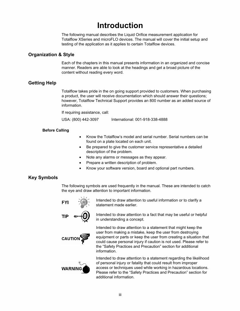
Key Symbols The following symbols are used frequently in the manual. These are intended to catch the eye and draw attention to important information.
Intended to draw attention to useful information or to clarify a statement made earlier.
Intended to draw attention to a fact that may be useful or helpful in understanding a concept.
Intended to draw attention to a statement that might keep the user from making a mistake, keep the user from destroying equipment or parts or keep the user from creating a situation that could cause personal injury if caution is not used. Please refer to the “Safety Practices and Precaution” section for additional information.
Intended to draw attention to a statement regarding the likelihood of personal injury or fatality that could result from improper access or techniques used while working in hazardous locations. Please refer to the “Safety Practices and Precaution” section for additional information.

iv
2012981-001 rev. AB 1
1.0 LIQUID ORIFICE OVERVIEW
The Liquid Orifice measurement application is designed to operate in conjunction with a flow computer and measure liquid volumes for a given material. This application is available for both Totalflow XSeries and microFLO devices.
This application is designed to perform calculations based on the standards determined in the API Manual of Petroleum Measurement Standards, Liquefied Petroleum Gas Measurement.
A liquid orifice measurement application is not available for XSeries G4 devices at this time.
2.0 ENABLING THE APPLICATION
It should be noted that the application might already be enabled, based on the device’s setup. If this is the case, skip the following procedure and move to Application Defaults.
The following steps will instruct the user on how to enable the Liquid Orifice application within PCCU.
1) Start PCCU. Once connected, move into Entry mode.
2) Move to the top of the tree-view, and click on the Station ID caption. This will bring up the main station setup tabs.
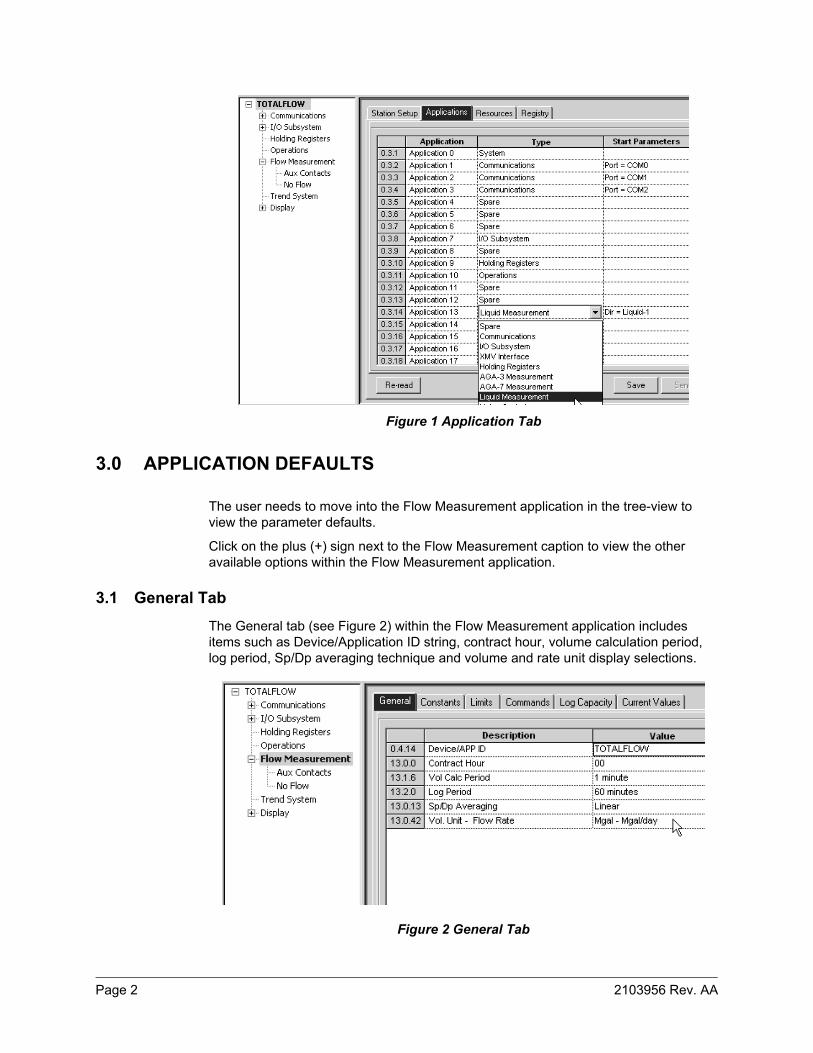
3) Click on the Applications tab (see Figure 1).
4) Within the Application tab, the user will instantiate the Liquid Measurement application. Locate an available slot (measurement applications need to be turned on within slots 11-18).
5) Upon location, click in the Type field. From the drop-down list, select Liquid Measurement. Once selected, click the Send button.
6) The user can then look at the tree-view. They will notice a Flow Measurement application has been added.
Page 2 2103956 Rev. AA
Figure 1 Application Tab
3.0 APPLICATION DEFAULTS
The user needs to move into the Flow Measurement application in the tree-view to view the parameter defaults.
Click on the plus (+) sign next to the Flow Measurement caption to view the other available options within the Flow Measurement application.
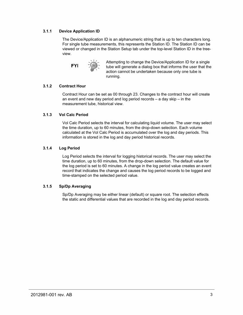
3.1 General Tab The General tab (see Figure 2) within the Flow Measurement application includes items such as Device/Application ID string, contract hour, volume calculation period, log period, Sp/Dp averaging technique and volume and rate unit display selections.
Figure 2 General Tab
2012981-001 rev. AB 3
3.1.1 Device Application ID
The Device/Application ID is an alphanumeric string that is up to ten characters long. For single tube measurements, this represents the Station ID. The Station ID can be viewed or changed in the Station Setup tab under the top-level Station ID in the tree-view.
Attempting to change the Device/Application ID for a single tube will generate a dialog box that informs the user that the action cannot be undertaken because only one tube is running.
3.1.2 Contract Hour
Contract Hour can be set as 00 through 23. Changes to the contract hour will create an event and new day period and log period records – a day skip – in the measurement tube, historical view.
3.1.3 Vol Calc Period
Vol Calc Period selects the interval for calculating liquid volume. The user may select the time duration, up to 60 minutes, from the drop-down selection. Each volume calculated at the Vol Calc Period is accumulated over the log and day periods. This information is stored in the log and day period historical records.
3.1.4 Log Period
Log Period selects the interval for logging historical records. The user may select the time duration, up to 60 minutes, from the drop-down selection. The default value for the log period is set to 60 minutes. A change in the log period value creates an event record that indicates the change and causes the log period records to be logged and time-stamped on the selected period value.
3.1.5 Sp/Dp Averaging
Sp/Dp Averaging may be either linear (default) or square root. The selection effects the static and differential values that are recorded in the log and day period records.
Page 4 2103956 Rev. AA
Linear average is calculated as the mathmatical mean of one-second samples over the log and day periods. Square root average is the sum of square root of one-second samples, squared, it is then divided by the number of samples.
• Linear Average Sp = ( Sp1 + Sp2 + Sp3 + … + Spn ) / n; where each Spn is a sample or reading of static pressure, and n is the number of samples or readings over the period.
• Linear Average Dp = ( Dp1 + Dp2 + Dp3 + … + Dpn ) / n; where each Dpn is a sample or reading of differential pressure, and n is the number of samples or readings over the period.
• Square root Average Sp = ((SqrSp1 + SqrSp2 + SqrSp3 + … + SqrSpn )/n) **2; where SqrSpn is the square root of a sample or one reading of static pressure, n is the number of samples or readings and **2 indicates raised to the 2nd power or squared.
• Square root Average Dp = (( SqrDp1 + SqrDp2 + SqrDp3 + … + SqrDpn)/n) **2; where SqrDpn is the square root of a sample or one reading of differential pressure, n is the number of samples or readings and **2 indicates raised to the 2nd power or squared.
3.1.6 Vol. Units – Flow Rate
Vol. Units – Flow Rate unit selections effect values that are displayed under the Current Values tab within the Flow Measurement application and on the FCU display. The available units are selectable from the field’s drop-down menu.
As displayed in the Current Values tab, today’s volume, yesterday’s volume and last calculated volume is scaled to units selected in the Vol. Unit half of the selection. Flow rate is scaled to the units shown on the Flow Rate side of the selection. For example, Mgal – gal/hr scales today’s volume, yesterday’s volume and last calculated volume to Mgal or thousands of US gallons, the flow rate to gal/hr or US gallons per hour. Unit string shown beside each value matches the selection string.
Display selections are described under the heading, Display.
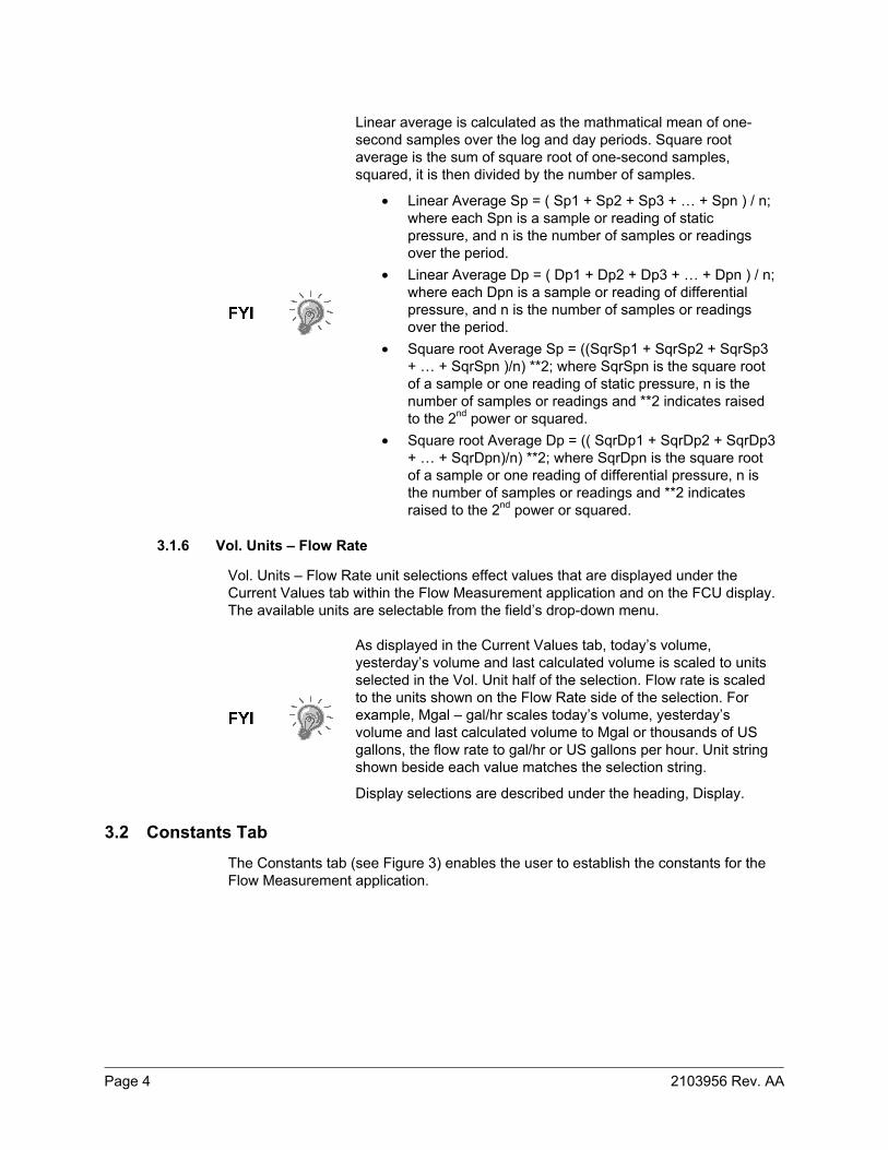
3.2 Constants Tab The Constants tab (see Figure 3) enables the user to establish the constants for the Flow Measurement application.
2012981-001 rev. AB 5
Figure 3 Constants Tab
3.2.1 Barometric Pressure
Barometric Pressure (PSIA) is a floating point number that represents the barometric pressure. Enter the current barometric pressure within the corresponding field.
3.2.2 Dp Zero Cutoff
Dp Zero Cutoff (In H20) is a floating point value that represents the lowest expected non-zero differential pressure reading. A reading less than this value will cause the value, 0.0, to be used for the differential pressure for flow rate and volume calculation. The value, shown under the Current Values tab within the Flow Measurement application, is filtered. To test this, use the following steps.
1) Set the Dp Zero Cutoff value to the Dp reading value. A holding register used for the Dp ensures that this is easy to test. A Dp transducer or Totalflow test box can be used.
2) Select the Current Values tab.
3) Click the Re-read button. Verify the Diff. Pressure Value is equal to or greater than the Dp Zero Cutoff.
To view information on how to test this feature, please refer to the Test section later in this manual.
3.2.3 Orifice Material
The Orifice Material field enables the user to make selections based on the type of material used for the orifice plate. The current selections are Stainless or Monel. The selection effects the orifice expansion factor (Fa). Changing this selection will effect flow rate by a relatively small amount. These rate changes can be viewed within the Current Values tab.
Page 6 2103956 Rev. AA
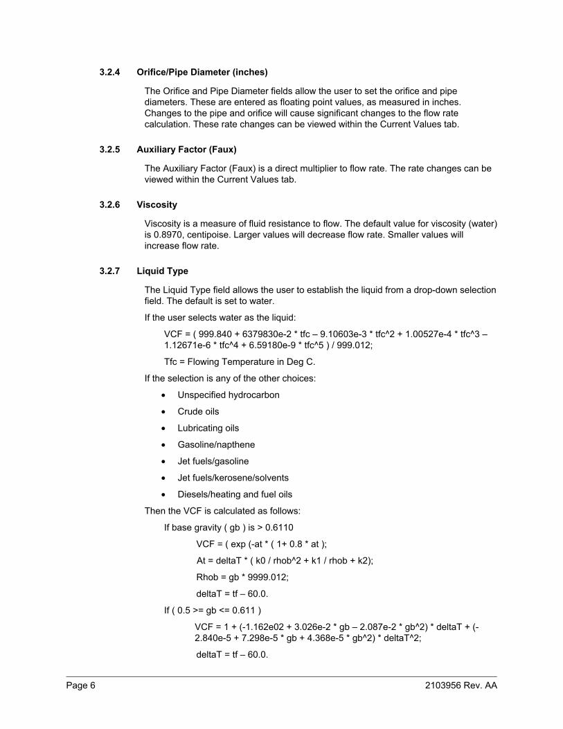
3.2.4 Orifice/Pipe Diameter (inches)
The Orifice and Pipe Diameter fields allow the user to set the orifice and pipe diameters. These are entered as floating point values, as measured in inches. Changes to the pipe and orifice will cause significant changes to the flow rate calculation. These rate changes can be viewed within the Current Values tab.
3.2.5 Auxiliary Factor (Faux)
The Auxiliary Factor (Faux) is a direct multiplier to flow rate. The rate changes can be viewed within the Current Values tab.
3.2.6 Viscosity
Viscosity is a measure of fluid resistance to flow. The default value for viscosity (water) is 0.8970, centipoise. Larger values will decrease flow rate. Smaller values will increase flow rate.
3.2.7 Liquid Type
The Liquid Type field allows the user to establish the liquid from a drop-down selection field. The default is set to water.
If the user selects water as the liquid:
VCF = ( 999.840 + 6379830e-2 * tfc – 9.10603e-3 * tfc^2 + 1.00527e-4 * tfc^3 – 1.12671e-6 * tfc^4 + 6.59180e-9 * tfc^5 ) / 999.012;
Tfc = Flowing Temperature in Deg C.
If the selection is any of the other choices:
• Unspecified hydrocarbon
• Crude oils
• Lubricating oils
• Gasoline/napthene
• Jet fuels/gasoline
• Jet fuels/kerosene/solvents
• Diesels/heating and fuel oils
Then the VCF is calculated as follows:
If base gravity ( gb ) is > 0.6110
VCF = ( exp (-at * ( 1+ 0.8 * at );
At = deltaT * ( k0 / rhob^2 + k1 / rhob + k2);
Rhob = gb * 9999.012;
deltaT = tf – 60.0.
If ( 0.5 >= gb <= 0.611 )
VCF = 1 + (-1.162e02 + 3.026e-2 * gb – 2.087e-2 * gb^2) * deltaT + (-2.840e-5 + 7.298e-5 * gb + 4.368e-5 * gb^2) * deltaT^2;
deltaT = tf – 60.0.
2012981-001 rev. AB 7
If ( gb < 0.5 )
VCF = 1.0.
If K0, K1 and K2 factors are all 0.0, VCF = 1.0.
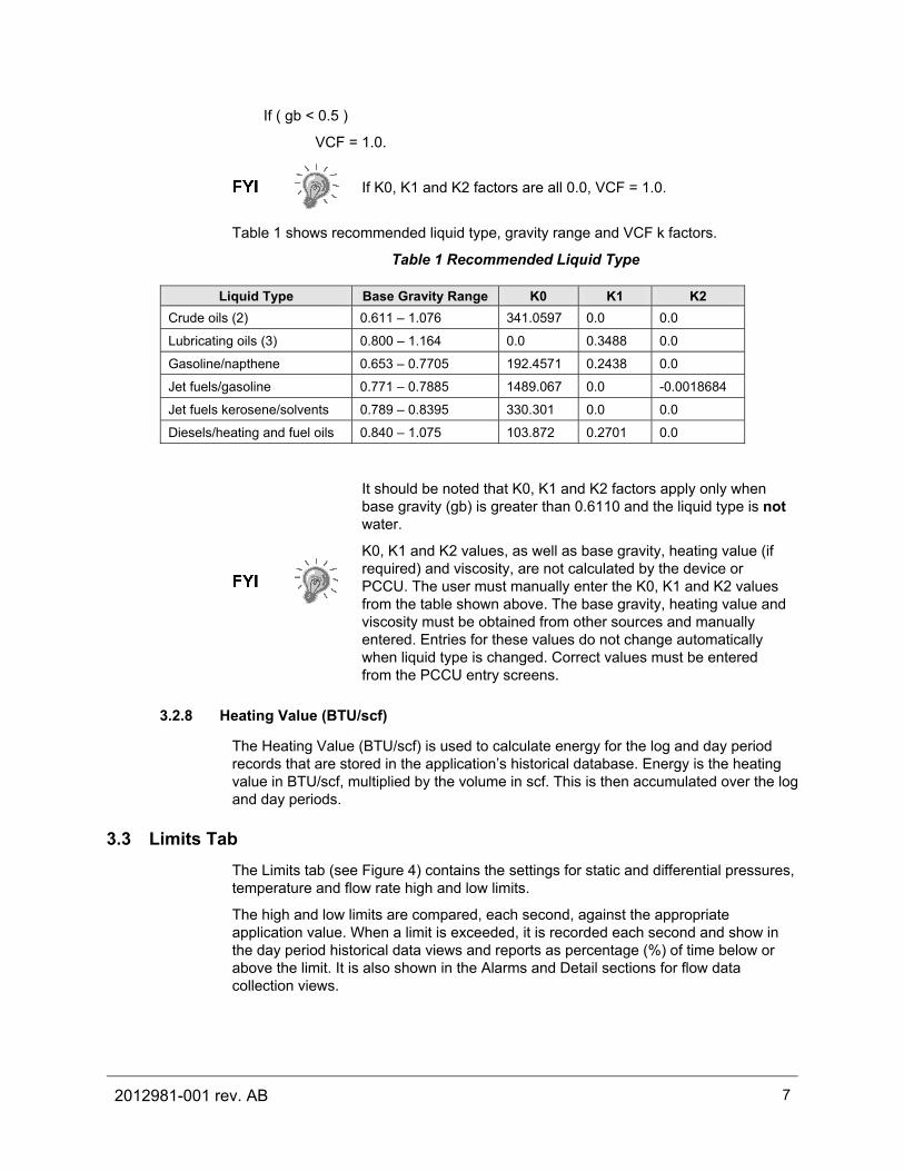
Table 1 shows recommended liquid type, gravity range and VCF k factors.
Table 1 Recommended Liquid Type
Liquid Type Base Gravity Range K0 K1 K2 Crude oils (2) 0.611 – 1.076 341.0597 0.0 0.0
Lubricating oils (3) 0.800 – 1.164 0.0 0.3488 0.0
Gasoline/napthene 0.653 – 0.7705 192.4571 0.2438 0.0
Jet fuels/gasoline 0.771 – 0.7885 1489.067 0.0 -0.0018684
Jet fuels kerosene/solvents 0.789 – 0.8395 330.301 0.0 0.0
Diesels/heating and fuel oils 0.840 – 1.075 103.872 0.2701 0.0
It should be noted that K0, K1 and K2 factors apply only when base gravity (gb) is greater than 0.6110 and the liquid type is not water.
K0, K1 and K2 values, as well as base gravity, heating value (if required) and viscosity, are not calculated by the device or PCCU. The user must manually enter the K0, K1 and K2 values from the table shown above. The base gravity, heating value and viscosity must be obtained from other sources and manually entered. Entries for these values do not change automatically when liquid type is changed. Correct values must be entered from the PCCU entry screens.
3.2.8 Heating Value (BTU/scf)
The Heating Value (BTU/scf) is used to calculate energy for the log and day period records that are stored in the application’s historical database. Energy is the heating value in BTU/scf, multiplied by the volume in scf. This is then accumulated over the log and day periods.
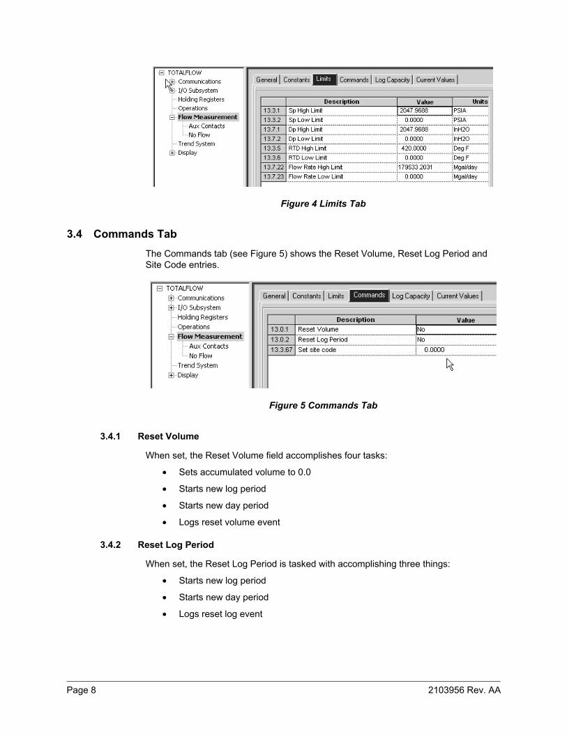
3.3 Limits Tab The Limits tab (see Figure 4) contains the settings for static and differential pressures, temperature and flow rate high and low limits.
The high and low limits are compared, each second, against the appropriate application value. When a limit is exceeded, it is recorded each second and show in the day period historical data views and reports as percentage (%) of time below or above the limit. It is also shown in the Alarms and Detail sections for flow data collection views.
Page 8 2103956 Rev. AA
Figure 4 Limits Tab
3.4 Commands Tab The Commands tab (see Figure 5) shows the Reset Volume, Reset Log Period and Site Code entries.
Figure 5 Commands Tab
3.4.1 Reset Volume
When set, the Reset Volume field accomplishes four tasks:
• Sets accumulated volume to 0.0
• Starts new log period
• Starts new day period
• Logs reset volume event
3.4.2 Reset Log Period
When set, the Reset Log Period is tasked with accomplishing three things:
• Starts new log period
• Starts new day period
• Logs reset log event
2012981-001 rev. AB 9
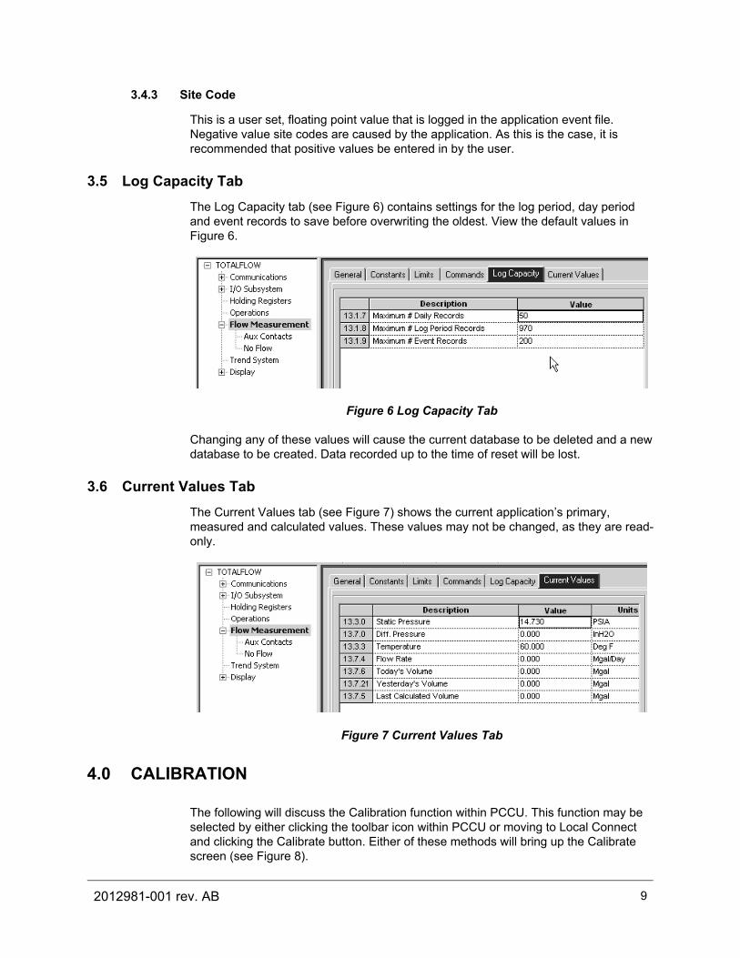
3.4.3 Site Code
This is a user set, floating point value that is logged in the application event file. Negative value site codes are caused by the application. As this is the case, it is recommended that positive values be entered in by the user.
3.5 Log Capacity Tab The Log Capacity tab (see Figure 6) contains settings for the log period, day period and event records to save before overwriting the oldest. View the default values in Figure 6.
Figure 6 Log Capacity Tab
Changing any of these values will cause the current database to be deleted and a new database to be created. Data recorded up to the time of reset will be lost.
3.6 Current Values Tab The Current Values tab (see Figure 7) shows the current application’s primary, measured and calculated values. These values may not be changed, as they are read-only.
Figure 7 Current Values Tab
4.0 CALIBRATION
The following will discuss the Calibration function within PCCU. This function may be selected by either clicking the toolbar icon within PCCU or moving to Local Connect and clicking the Calibrate button. Either of these methods will bring up the Calibrate screen (see Figure 8).

Page 10 2103956 Rev. AA
Figure 8 Calibration Setup Screen
The static pressure, differential pressure and temperature registers must be set to I/O or XMV registers to allow for calibration.
4.1 Calibration Checks Tab The Calibration Checks tab (see Figure 9) allows the current measured values to be tested and logged as events when they are compared to a known benchmark test.
Figure 9 Calibration Checks Tab
Clicking the Enter Pressure Check Value button will display the Enter Pressure dialog box. Within the box, the user can enter a corresponding value. When the measured value stabilizes, clicking the OK button will log the device’s measured value, and the customer entered value. This value is then displayed in the Checks grid.
2012981-001 rev. AB 11
If the user chooses to move to the Events Collection view, they will be able to see the Dp calibration check event, as entered.
Additionally, the user can use the drop-down menu to select Dp, Sp, Tf or DP & Sp.
By entering these values, the user will log the values into Events the event log.
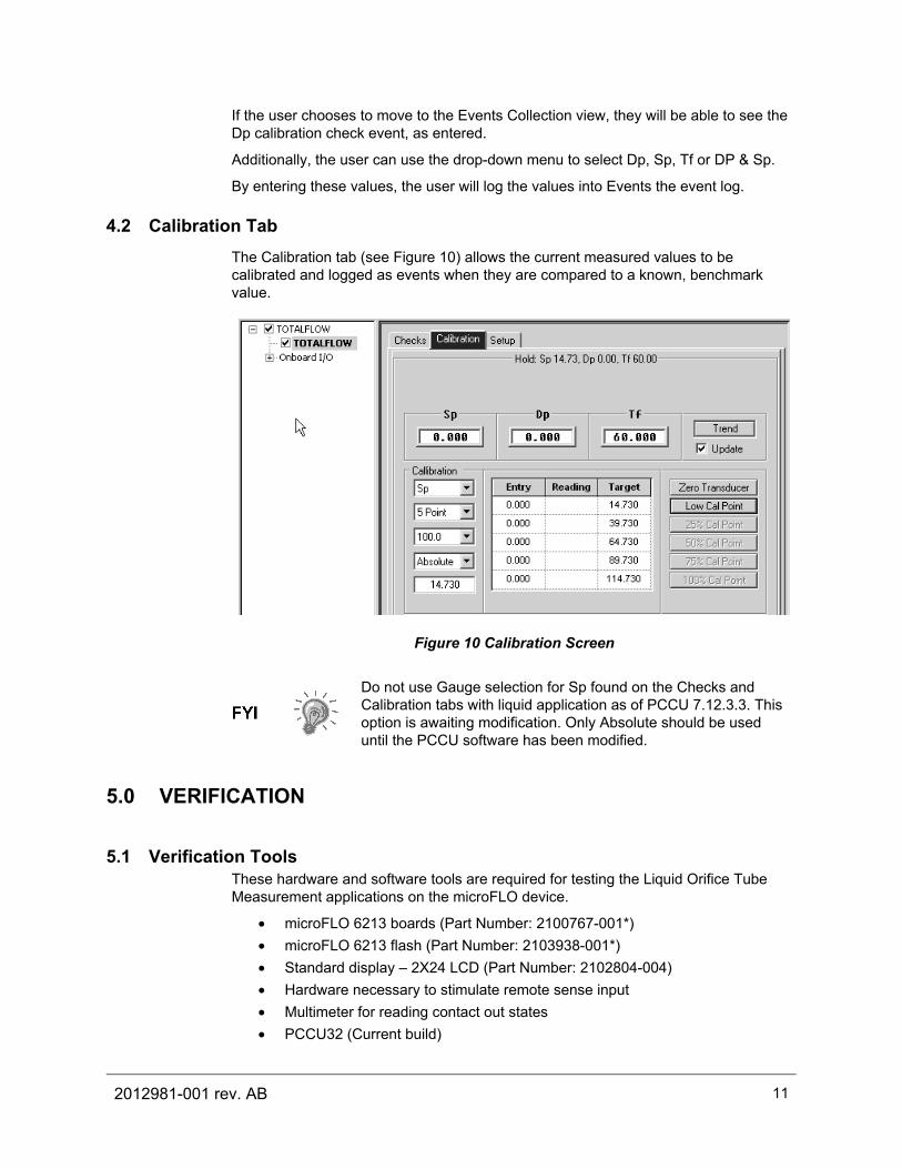
4.2 Calibration Tab The Calibration tab (see Figure 10) allows the current measured values to be calibrated and logged as events when they are compared to a known, benchmark value.
Figure 10 Calibration Screen
Do not use Gauge selection for Sp found on the Checks and Calibration tabs with liquid application as of PCCU 7.12.3.3. This option is awaiting modification. Only Absolute should be used until the PCCU software has been modified.
5.0 VERIFICATION
5.1 Verification Tools These hardware and software tools are required for testing the Liquid Orifice Tube Measurement applications on the microFLO device.
• microFLO 6213 boards (Part Number: 2100767-001*) • microFLO 6213 flash (Part Number: 2103938-001*) • Standard display – 2X24 LCD (Part Number: 2102804-004) • Hardware necessary to stimulate remote sense input • Multimeter for reading contact out states • PCCU32 (Current build)
Page 12 2103956 Rev. AA
* These screens and tests apply to the Liquid Orifice Tube Measurement application that is running on G3, XFC and XRC.
5.2 Verifying Configuration The following test requires that a liquid measurement tube be enabled and configured correctly. Holding registers also need to be enabled within PCCU.
1) Within PCCU, click on Holding Registers. Upon opening the feature, click the Capacity tab. Verify that Descriptors are enabled for ‘floats’.
2) Next, within the Holding Registers feature, click on the Float tab.
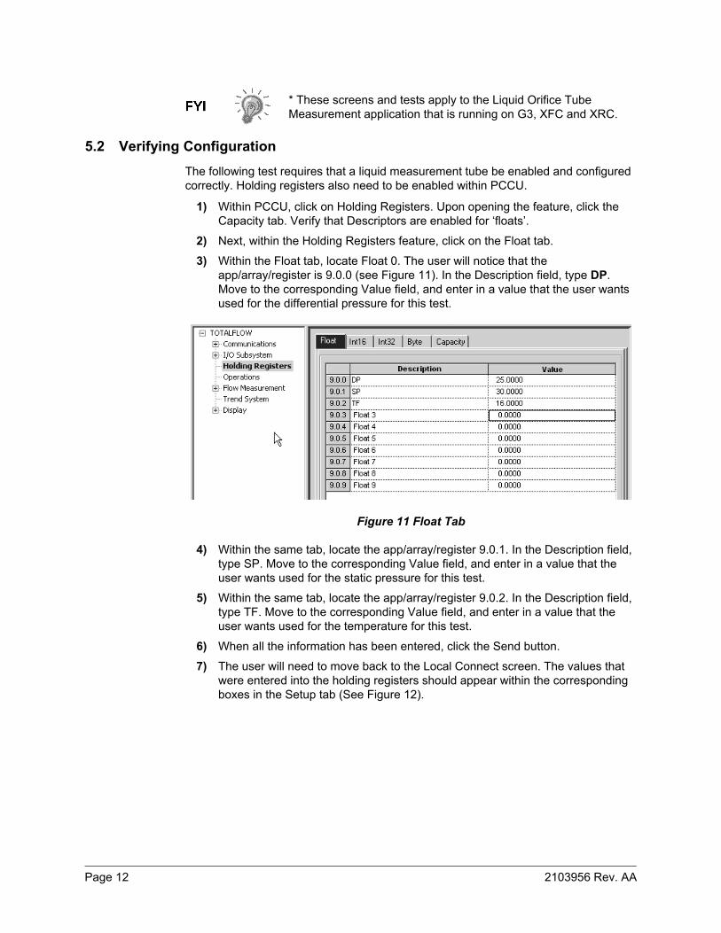
3) Within the Float tab, locate Float 0. The user will notice that the app/array/register is 9.0.0 (see Figure 11). In the Description field, type DP. Move to the corresponding Value field, and enter in a value that the user wants used for the differential pressure for this test.
Figure 11 Float Tab
4) Within the same tab, locate the app/array/register 9.0.1. In the Description field, type SP. Move to the corresponding Value field, and enter in a value that the user wants used for the static pressure for this test.
5) Within the same tab, locate the app/array/register 9.0.2. In the Description field, type TF. Move to the corresponding Value field, and enter in a value that the user wants used for the temperature for this test.
6) When all the information has been entered, click the Send button.
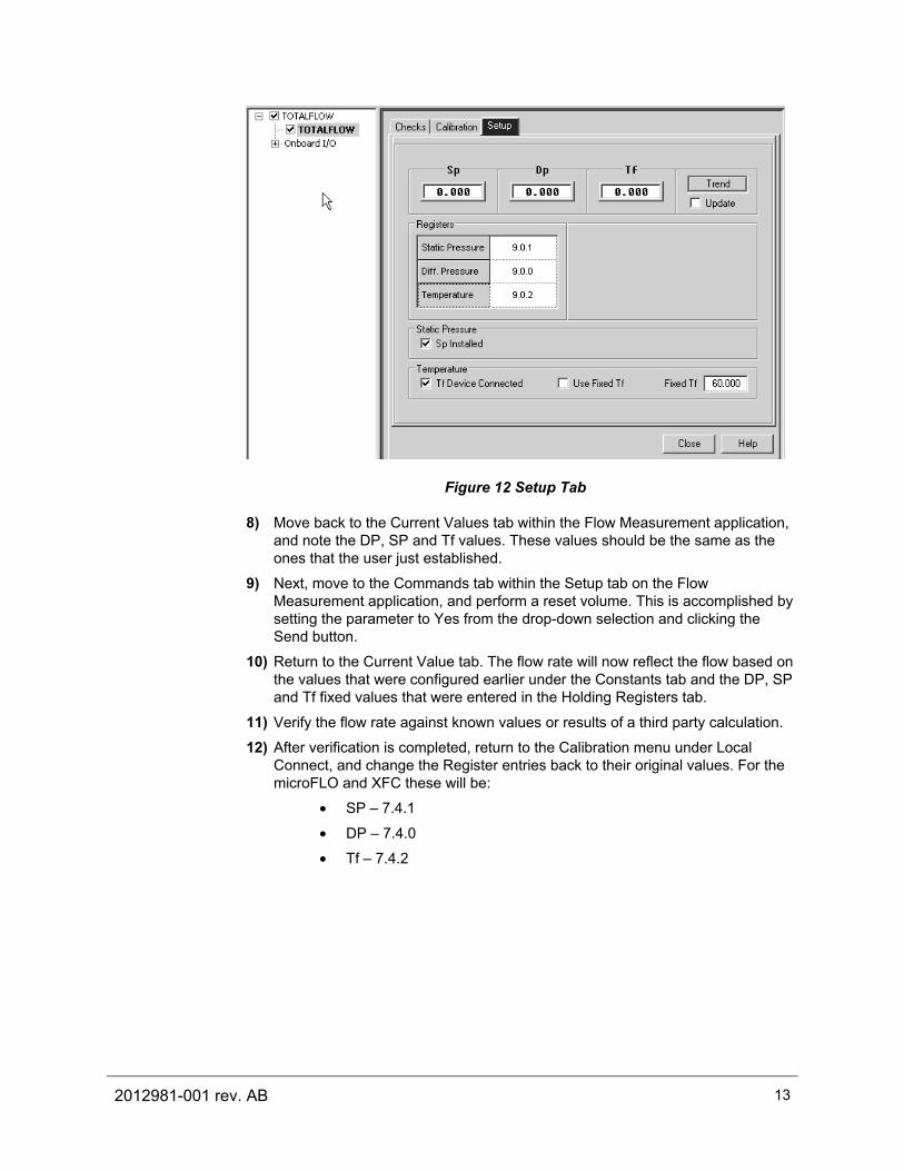
7) The user will need to move back to the Local Connect screen. The values that were entered into the holding registers should appear within the corresponding boxes in the Setup tab (See Figure 12).
2012981-001 rev. AB 13
Figure 12 Setup Tab
8) Move back to the Current Values tab within the Flow Measurement application, and note the DP, SP and Tf values. These values should be the same as the ones that the user just established.
9) Next, move to the Commands tab within the Setup tab on the Flow Measurement application, and perform a reset volume. This is accomplished by setting the parameter to Yes from the drop-down selection and clicking the Send button.
10) Return to the Current Value tab. The flow rate will now reflect the flow based on the values that were configured earlier under the Constants tab and the DP, SP and Tf fixed values that were entered in the Holding Registers tab.
11) Verify the flow rate against known values or results of a third party calculation.
12) After verification is completed, return to the Calibration menu under Local Connect, and change the Register entries back to their original values. For the microFLO and XFC these will be:
• SP – 7.4.1
• DP – 7.4.0
• Tf – 7.4.2

©Copyright 2010 ABB, All rights reserved
Document Title
Totalflow G3 Liquid Orifice Measurement Application Guide Document No. Date & Rev. Ind. No. of Pages
2012981-001 AB 20