Embed Size (px)
Citation preview
March 2014 www.cae-sim-sol.com
Fatigue Assessment with LIMIT According to Eurocode 3 Version LIMIT2014
Documentation
page 2 LIMIT, Fatigue Strength Assessments According to Eurocode 3 www.cae-sim-sol.com
Fatigue Assessment with LIMIT According to Eurocode 3
Motivation
Stresses and section forces
Stress spectra
Stress-relieved welded details in compression
FAT classes
S-N curves
Fatigue analysis
Results
Overview
page 3 LIMIT, Fatigue Strength Assessments According to Eurocode 3 www.cae-sim-sol.com
Motivation
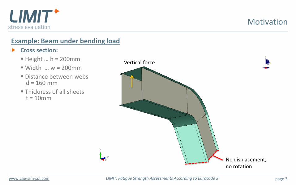
Example: Beam under bending load Cross section:
Height … h = 200mm
Width … w = 200mm
Distance between webs d = 160 mm
Thickness of all sheets t = 10mm
No displacement, no rotation
Vertical force
page 4 LIMIT, Fatigue Strength Assessments According to Eurocode 3 www.cae-sim-sol.com
Motivation
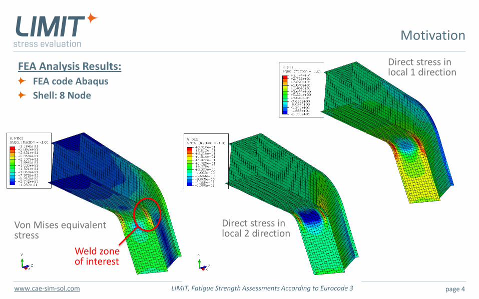
FEA Analysis Results: FEA code Abaqus
Shell: 8 Node
Von Mises equivalent stress
Direct stress in local 2 direction
Direct stress in local 1 direction
Weld zone of interest
page 5 LIMIT, Fatigue Strength Assessments According to Eurocode 3 www.cae-sim-sol.com
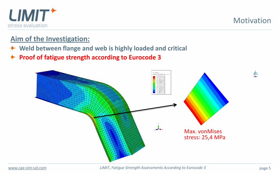
Aim of the Investigation: Weld between flange and web is highly loaded and critical
Proof of fatigue strength according to Eurocode 3
Motivation
Max. vonMises stress: 25,4 MPa
page 6 LIMIT, Fatigue Strength Assessments According to Eurocode 3 www.cae-sim-sol.com
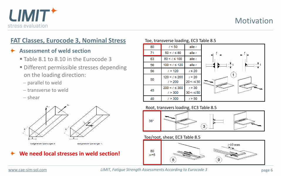
FAT Classes, Eurocode 3, Nominal Stress
Assessment of weld section
Table 8.1 to 8.10 in the Eurocode 3
Different permissible stresses depending on the loading direction:
parallel to weld
transverse to weld
shear
We need local stresses in weld section!
Motivation
Toe, transverse loading, EC3 Table 8.5
Root, transvers loading, EC3 Table 8.5
Toe/root, shear, EC3 Table 8.5
page 7 LIMIT, Fatigue Strength Assessments According to Eurocode 3 www.cae-sim-sol.com
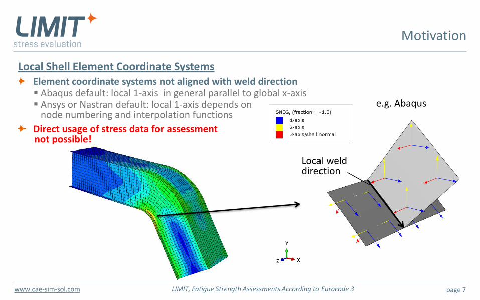
Local Shell Element Coordinate Systems Element coordinate systems not aligned with weld direction Abaqus default: local 1-axis in general parallel to global x-axis Ansys or Nastran default: local 1-axis depends on node numbering and interpolation functions
Direct usage of stress data for assessment not possible!
Motivation
Local weld direction
e.g. Abaqus
page 8 LIMIT, Fatigue Strength Assessments According to Eurocode 3 www.cae-sim-sol.com
Motivation
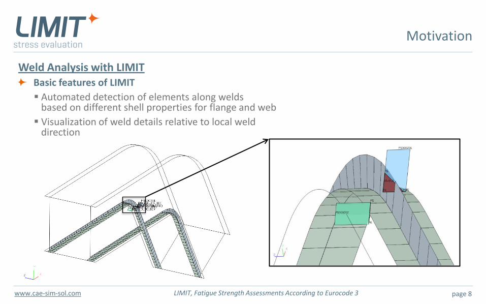
Weld Analysis with LIMIT Basic features of LIMIT
Automated detection of elements along welds based on different shell properties for flange and web
Visualization of weld details relative to local weld direction
page 9 LIMIT, Fatigue Strength Assessments According to Eurocode 3 www.cae-sim-sol.com
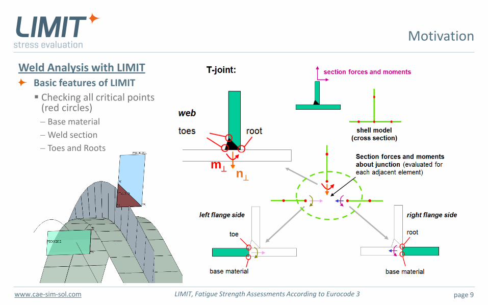
Motivation
n m
Weld Analysis with LIMIT Basic features of LIMIT
Checking all critical points (red circles)
Base material
Weld section
Toes and Roots
page 10 LIMIT, Fatigue Strength Assessments According to Eurocode 3 www.cae-sim-sol.com
Overview
Fatigue Assessment with LIMIT According to Eurocode 3
Motivation
Stresses and section forces
Stress spectra
Stress-relieved welded details in compression
FAT classes
S-N curves
Fatigue analysis
Results
page 11 LIMIT, Fatigue Strength Assessments According to Eurocode 3 www.cae-sim-sol.com
Stresses and Section Forces
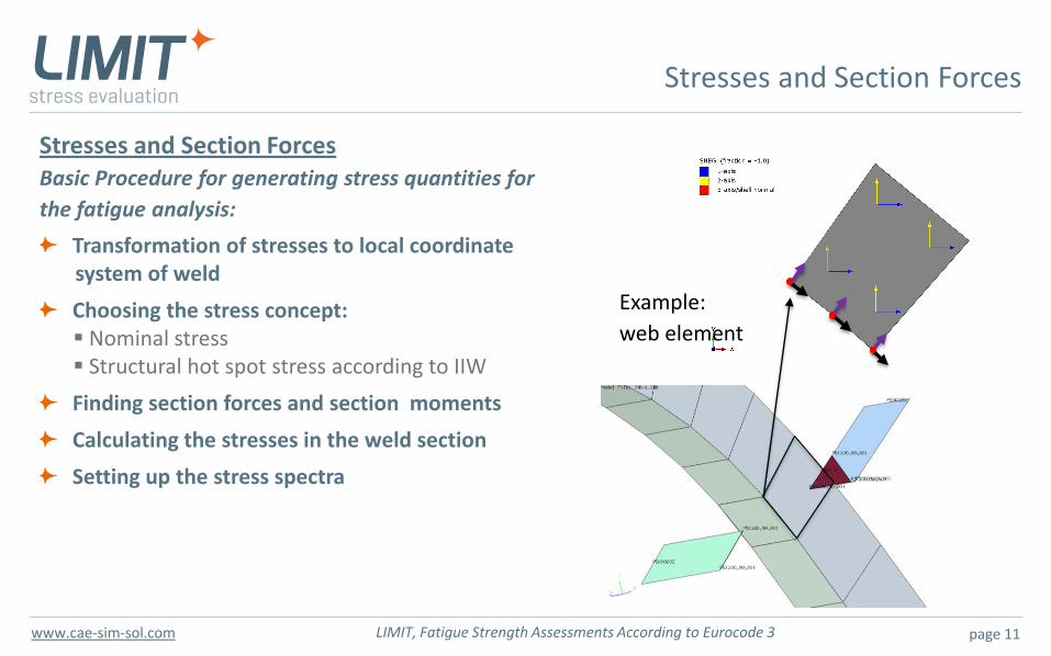
Stresses and Section Forces Basic Procedure for generating stress quantities for
the fatigue analysis:
Transformation of stresses to local coordinate system of weld
Choosing the stress concept: Nominal stress Structural hot spot stress according to IIW
Finding section forces and section moments
Calculating the stresses in the weld section
Setting up the stress spectra
Example:
web element
page 12 LIMIT, Fatigue Strength Assessments According to Eurocode 3 www.cae-sim-sol.com
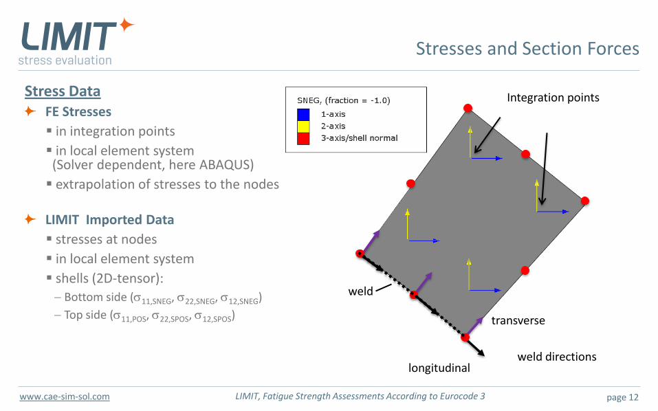
transverse
longitudinal weld directions
Integration points Stress Data FE Stresses
in integration points
in local element system (Solver dependent, here ABAQUS)
extrapolation of stresses to the nodes
LIMIT Imported Data
stresses at nodes
in local element system
shells (2D-tensor): Bottom side (s11,SNEG, s22,SNEG, s12,SNEG)
Top side (s11,POS, s22,SPOS, s12,SPOS)
weld
Stresses and Section Forces
page 13 LIMIT, Fatigue Strength Assessments According to Eurocode 3 www.cae-sim-sol.com
transverse
longitudinal weld directions
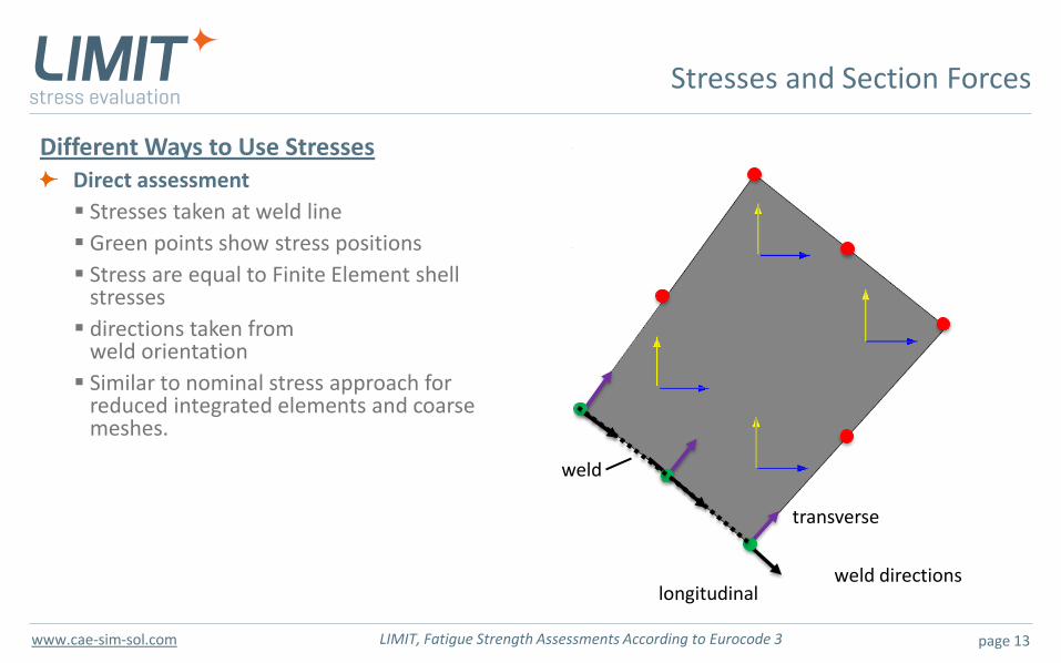
Different Ways to Use Stresses Direct assessment
Stresses taken at weld line
Green points show stress positions
Stress are equal to Finite Element shell stresses
directions taken from weld orientation
Similar to nominal stress approach for reduced integrated elements and coarse meshes.
weld
Stresses and Section Forces
page 14 LIMIT, Fatigue Strength Assessments According to Eurocode 3 www.cae-sim-sol.com
transverse
longitudinal weld orientation
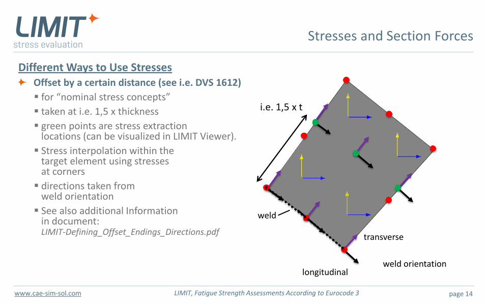
Different Ways to Use Stresses Offset by a certain distance (see i.e. DVS 1612)
for “nominal stress concepts”
taken at i.e. 1,5 x thickness
green points are stress extraction locations (can be visualized in LIMIT Viewer).
Stress interpolation within the target element using stresses at corners
directions taken from weld orientation
See also additional Information in document: LIMIT-Defining_Offset_Endings_Directions.pdf
i.e. 1,5 x t
weld
Stresses and Section Forces
page 15 LIMIT, Fatigue Strength Assessments According to Eurocode 3 www.cae-sim-sol.com
transverse
longitudinal weld directions
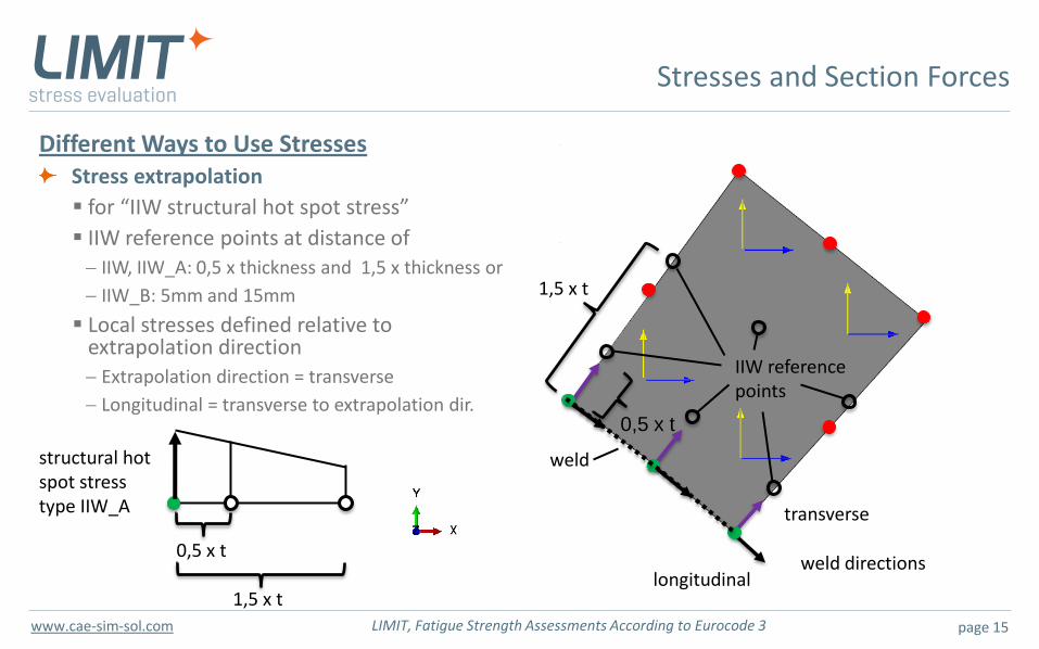
Different Ways to Use Stresses Stress extrapolation
for “IIW structural hot spot stress”
IIW reference points at distance of IIW, IIW_A: 0,5 x thickness and 1,5 x thickness or
IIW_B: 5mm and 15mm
Local stresses defined relative to extrapolation direction
Extrapolation direction = transverse
Longitudinal = transverse to extrapolation dir.
1,5 x t
0,5 x t
0,5 x t
1,5 x t
structural hot spot stress type IIW_A
IIW reference points
weld
Stresses and Section Forces
page 16 LIMIT, Fatigue Strength Assessments According to Eurocode 3 www.cae-sim-sol.com
… transverse
lI…parallel
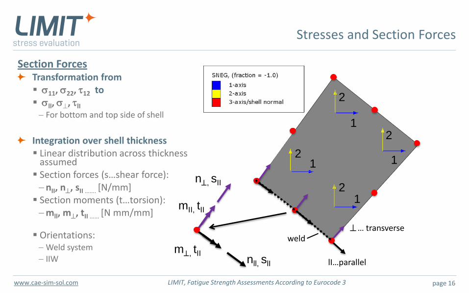
Section Forces Transformation from s11, s22, t12 to sll, s, tlI
For bottom and top side of shell
Integration over shell thickness Linear distribution across thickness assumed Section forces (s…shear force):
nII, n, sII ……. [N/mm] Section moments (t…torsion):
mll, m, tII …… [N mm/mm]
Orientations: Weld system
IIW
1
1
1 1 2
2
2
2
m, tII
nll, slI
mII, tII
n, sII
weld
Stresses and Section Forces
page 17 LIMIT, Fatigue Strength Assessments According to Eurocode 3 www.cae-sim-sol.com
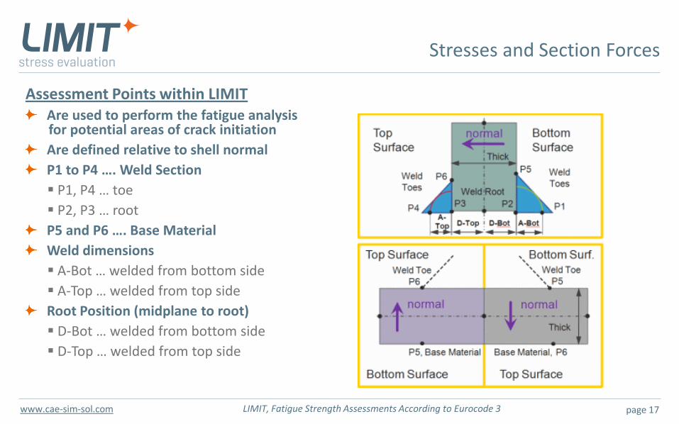
Assessment Points within LIMIT Are used to perform the fatigue analysis
for potential areas of crack initiation
Are defined relative to shell normal
P1 to P4 …. Weld Section
P1, P4 … toe
P2, P3 … root
P5 and P6 …. Base Material
Weld dimensions
A-Bot … welded from bottom side
A-Top … welded from top side
Root Position (midplane to root)
D-Bot … welded from bottom side
D-Top … welded from top side
Stresses and Section Forces
page 18 LIMIT, Fatigue Strength Assessments According to Eurocode 3 www.cae-sim-sol.com
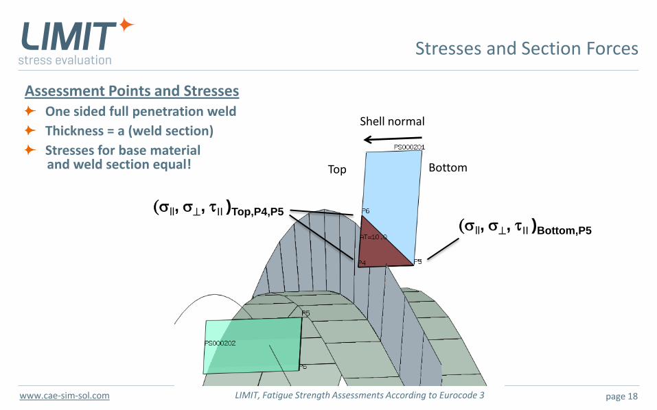
Assessment Points and Stresses One sided full penetration weld
Thickness = a (weld section)
Stresses for base material and weld section equal!
Stresses and Section Forces
(sll, s, tII )Bottom,P5
Bottom Top
Shell normal
(sll, s, tII )Top,P4,P5
page 19 LIMIT, Fatigue Strength Assessments According to Eurocode 3 www.cae-sim-sol.com
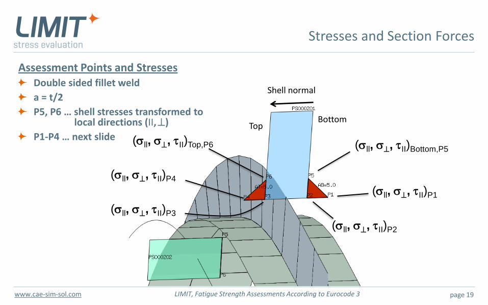
Assessment Points and Stresses Double sided fillet weld
a = t/2
P5, P6 … shell stresses transformed to local directions (II, )
P1-P4 … next slide
Stresses and Section Forces
(sll, s, tII)Bottom,P5
Bottom Top
Shell normal
(sll, s, tII)Top,P6
(sll, s, tII)P1
(sll, s, tII)P2
(sll, s, tII)P4
(sll, s, tII)P3
page 20 LIMIT, Fatigue Strength Assessments According to Eurocode 3 www.cae-sim-sol.com
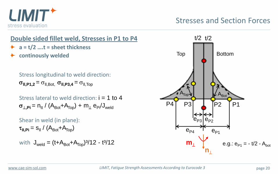
Double sided fillet weld, Stresses in P1 to P4 a = t/2 ….t = sheet thickness
continously welded
Stresses and Section Forces
Stress longitudinal to weld direction: sll,P1,2 = sll,Bot, sll,P3,4 = sll,Top
Stress lateral to weld direction: i = 1 to 4
s,Pi = ntt / (ABot+ATop) + m ePi/Jweld
Shear in weld (in plane): tII,Pi = sIl / (ABot+ATop)
with Jweld = (t+ABot+ATop)³/12 - t³/12
Bottom Top
ABot ATop
eP4 eP1
eP2 eP3
P4 P3 P1 P2
e.g.: eP1 = - t/2 - Abot
t/2 t/2
n m
page 21 LIMIT, Fatigue Strength Assessments According to Eurocode 3 www.cae-sim-sol.com
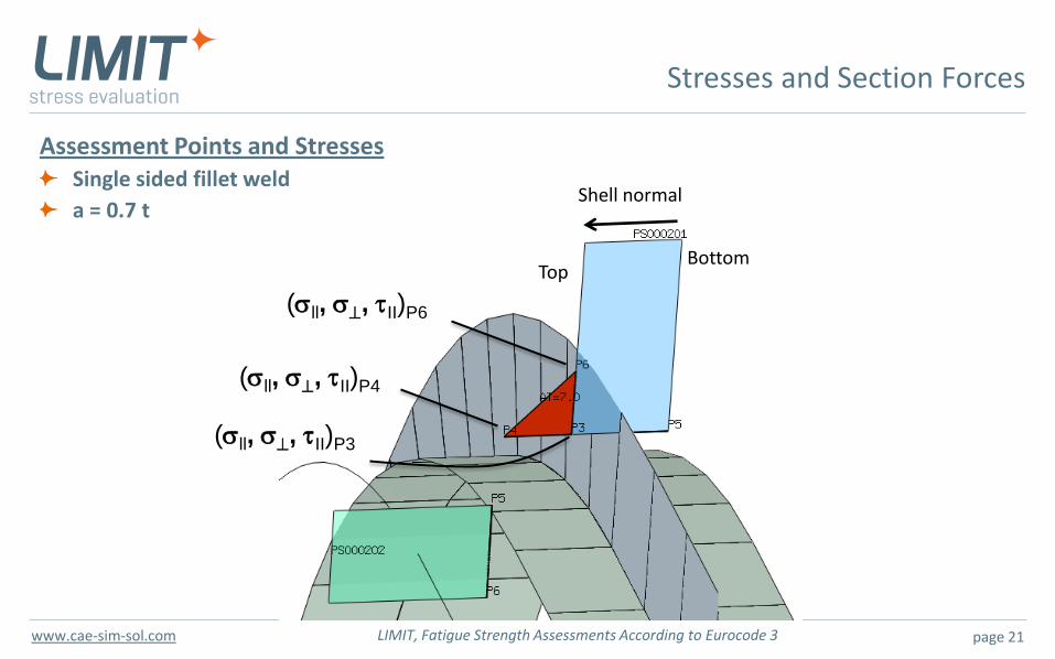
Assessment Points and Stresses Single sided fillet weld
a = 0.7 t
Stresses and Section Forces
Bottom Top
Shell normal
(sll, s, tII)P6
(sll, s, tII)P4
(sll, s, tII)P3
page 22 LIMIT, Fatigue Strength Assessments According to Eurocode 3 www.cae-sim-sol.com
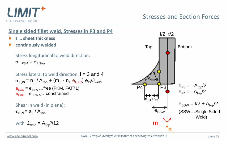
Single sided fillet weld, Stresses in P3 and P4 t … sheet thickness
continously welded
Stresses and Section Forces
Stress longitudinal to weld direction: sll,P3,4 = sll,Top
Stress lateral to weld direction: i = 3 and 4
s,Pi = n / ATop + (m - n eEXC) ePi/Jweld
eEXC = eSSW …free (FKM, FAT71)
eEXC = eSSW /2…constrained
Shear in weld (in plane): tIl,Pi = sIl / ATop
with Jweld = ATop³/12
Bottom Top
ATop
P4 P3 eP3 = -Atop/2
eP4 = Atop/2
eSSW = t/2 + Atop/2
(SSW…Single Sided
Weld)
t/2 t/2
n m
eP4 eP3
eSSW
page 23 LIMIT, Fatigue Strength Assessments According to Eurocode 3 www.cae-sim-sol.com
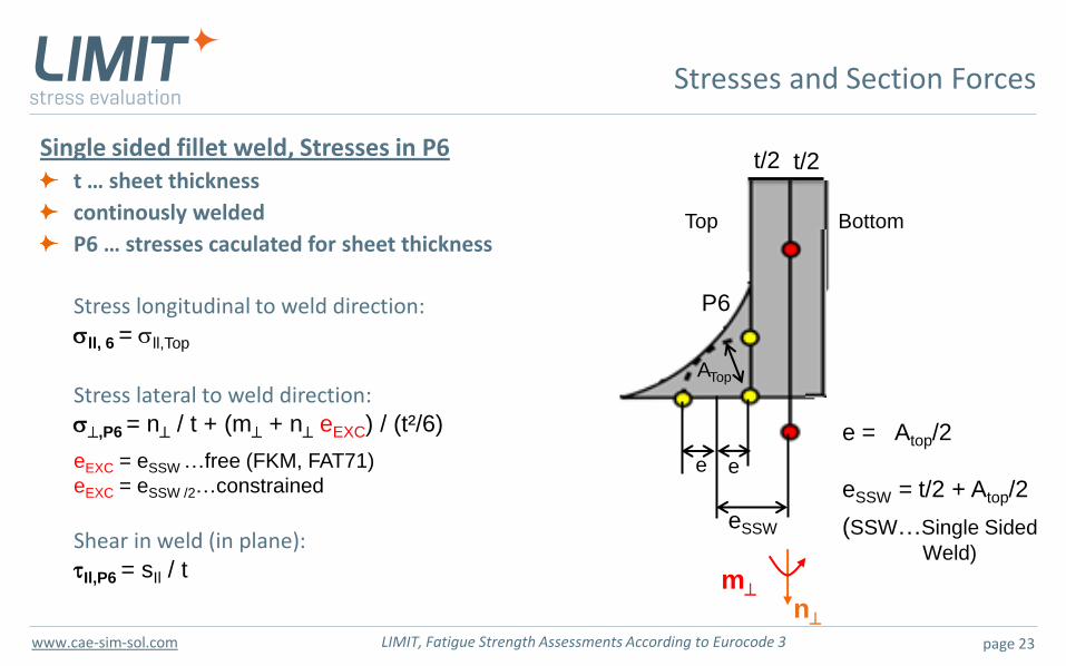
Single sided fillet weld, Stresses in P6 t … sheet thickness
continously welded
P6 … stresses caculated for sheet thickness
Stresses and Section Forces
Stress longitudinal to weld direction: sll, 6 = sll,Top
Stress lateral to weld direction: s,P6 = n / t + (m + n eEXC) / (t²/6)
eEXC = eSSW …free (FKM, FAT71)
eEXC = eSSW /2…constrained
Shear in weld (in plane): tIl,P6 = sIl / t
Bottom Top
ATop
e = Atop/2
eSSW = t/2 + Atop/2
(SSW…Single Sided
Weld)
t/2 t/2
n m
e e
eSSW
P6
page 24 LIMIT, Fatigue Strength Assessments According to Eurocode 3 www.cae-sim-sol.com
Overview
Fatigue Assessment with LIMIT According to Eurocode 3
Motivation
Stresses and section forces
Stress spectra
Stress-relieved welded details in compression
FAT classes
S-N curves
Fatigue analysis
Results
page 25 LIMIT, Fatigue Strength Assessments According to Eurocode 3 www.cae-sim-sol.com
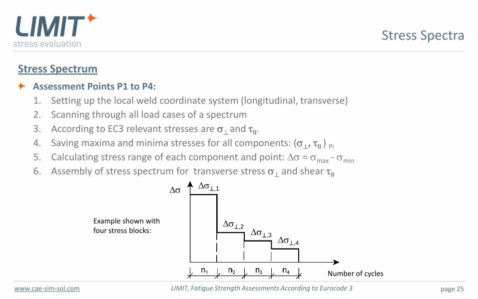
Stress Spectrum
Assessment Points P1 to P4:
1. Setting up the local weld coordinate system (longitudinal, transverse)
2. Scanning through all load cases of a spectrum
3. According to EC3 relevant stresses are s and tlI.
4. Saving maxima and minima stresses for all components: (s, tlI ) Pi
5. Calculating stress range of each component and point: Ds = smax - smin
6. Assembly of stress spectrum for transverse stress s and shear tlI
Stress Spectra
Ds,1
Ds,2 Ds,3
Number of cycles
Ds,4
Ds
Example shown with four stress blocks:
page 26 LIMIT, Fatigue Strength Assessments According to Eurocode 3 www.cae-sim-sol.com
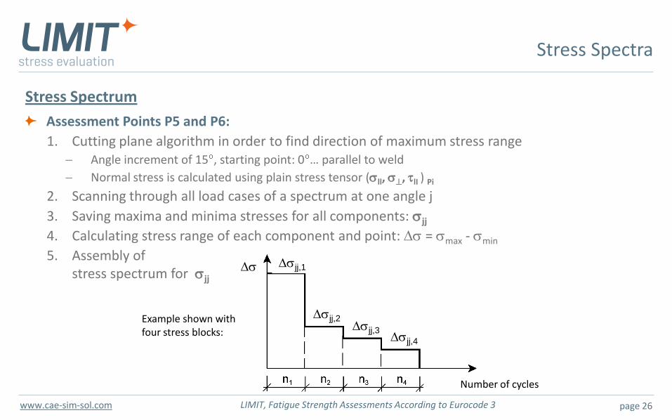
Stress Spectrum
Assessment Points P5 and P6:
1. Cutting plane algorithm in order to find direction of maximum stress range Angle increment of 15 , starting point: 0 … parallel to weld
Normal stress is calculated using plain stress tensor (sll, s, tlI ) Pi
2. Scanning through all load cases of a spectrum at one angle j
3. Saving maxima and minima stresses for all components: sjj
4. Calculating stress range of each component and point: Ds = smax - smin
5. Assembly of stress spectrum for sjj
Stress Spectra
Dsjj,1
Dsjj,2 Dsjj,3
Number of cycles
Dsjj,4
Ds
Example shown with four stress blocks:
page 27 LIMIT, Fatigue Strength Assessments According to Eurocode 3 www.cae-sim-sol.com
Overview
Fatigue Assessment with LIMIT According to Eurocode 3
Motivation
Stresses and section forces
Stress spectra
Stress-relieved welded details in compression
FAT classes
S-N curves
Fatigue analysis
Results
page 28 LIMIT, Fatigue Strength Assessments According to Eurocode 3 www.cae-sim-sol.com
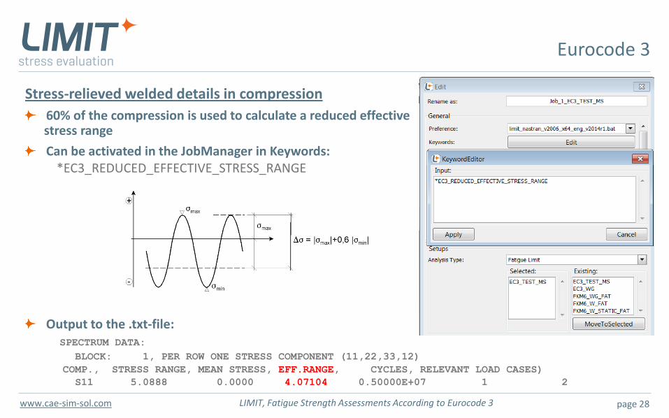
Stress-relieved welded details in compression
60% of the compression is used to calculate a reduced effective stress range
Can be activated in the JobManager in Keywords: *EC3_REDUCED_EFFECTIVE_STRESS_RANGE
Output to the .txt-file: SPECTRUM DATA: BLOCK: 1, PER ROW ONE STRESS COMPONENT (11,22,33,12)
COMP., STRESS RANGE, MEAN STRESS, EFF.RANGE, CYCLES, RELEVANT LOAD CASES)
S11 5.0888 0.0000 4.07104 0.50000E+07 1 2
Eurocode 3
page 29 LIMIT, Fatigue Strength Assessments According to Eurocode 3 www.cae-sim-sol.com
Overview
Fatigue Assessment with LIMIT According to Eurocode 3
Motivation
Stresses and section forces
Stress spectra
Stress-relieved welded details in compression
FAT classes
S-N curves
Fatigue analysis
Results
page 30 LIMIT, Fatigue Strength Assessments According to Eurocode 3 www.cae-sim-sol.com
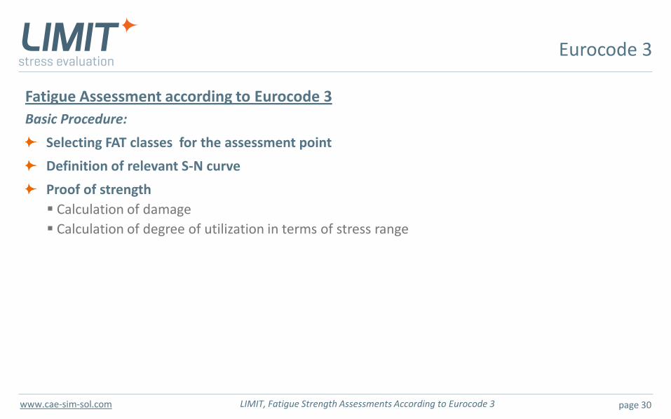
Fatigue Assessment according to Eurocode 3
Basic Procedure:
Selecting FAT classes for the assessment point
Definition of relevant S-N curve
Proof of strength
Calculation of damage
Calculation of degree of utilization in terms of stress range
Eurocode 3
page 31 LIMIT, Fatigue Strength Assessments According to Eurocode 3 www.cae-sim-sol.com
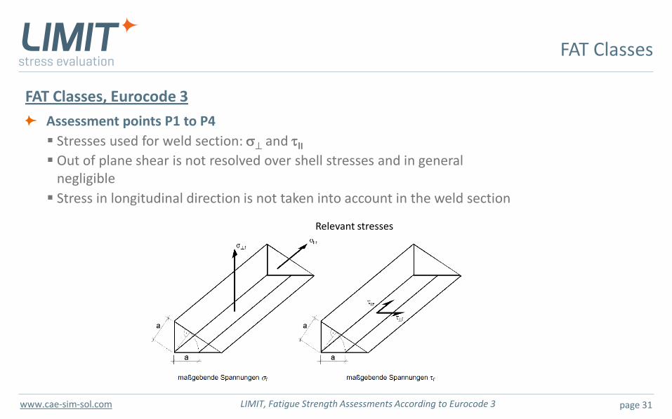
FAT Classes, Eurocode 3
Assessment points P1 to P4
Stresses used for weld section: s and tlI
Out of plane shear is not resolved over shell stresses and in general negligible
Stress in longitudinal direction is not taken into account in the weld section
FAT Classes
Relevant stresses
page 32 LIMIT, Fatigue Strength Assessments According to Eurocode 3 www.cae-sim-sol.com
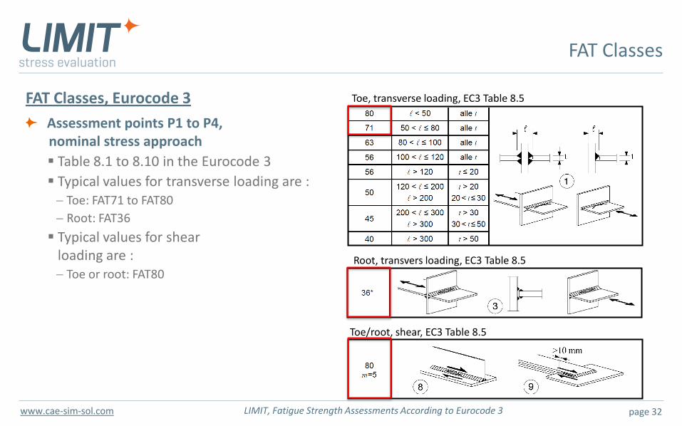
FAT Classes, Eurocode 3
Assessment points P1 to P4, nominal stress approach
Table 8.1 to 8.10 in the Eurocode 3
Typical values for transverse loading are : Toe: FAT71 to FAT80
Root: FAT36
Typical values for shear loading are :
Toe or root: FAT80
FAT Classes
Toe, transverse loading, EC3 Table 8.5
Root, transvers loading, EC3 Table 8.5
Toe/root, shear, EC3 Table 8.5
page 33 LIMIT, Fatigue Strength Assessments According to Eurocode 3 www.cae-sim-sol.com
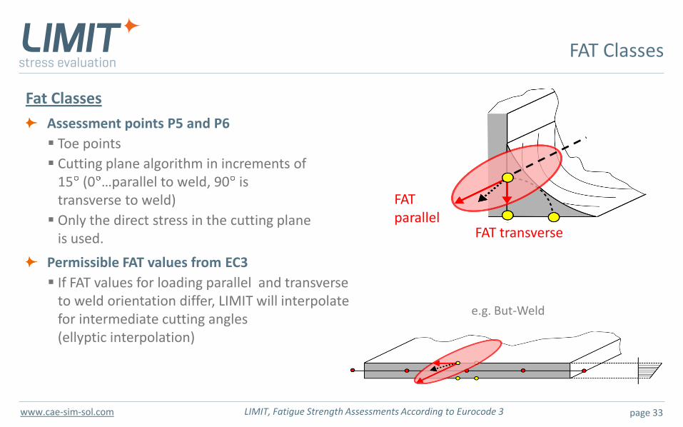
Fat Classes
Assessment points P5 and P6
Toe points
Cutting plane algorithm in increments of 15 (0 …parallel to weld, 90 is transverse to weld)
Only the direct stress in the cutting plane is used.
Permissible FAT values from EC3
If FAT values for loading parallel and transverse to weld orientation differ, LIMIT will interpolate for intermediate cutting angles (ellyptic interpolation)
FAT Classes
e.g. But-Weld
FAT parallel
FAT transverse
page 34 LIMIT, Fatigue Strength Assessments According to Eurocode 3 www.cae-sim-sol.com
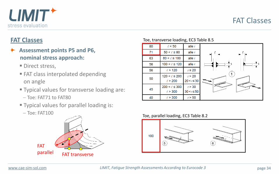
FAT Classes
Assessment points P5 and P6, nominal stress approach:
Direct stress,
FAT class interpolated depending on angle
Typical values for transverse loading are: Toe: FAT71 to FAT80
Typical values for parallel loading is: Toe: FAT100
FAT Classes
Toe, transverse loading, EC3 Table 8.5
Toe, parallel loading, EC3 Table 8.2
FAT parallel FAT transverse
page 35 LIMIT, Fatigue Strength Assessments According to Eurocode 3 www.cae-sim-sol.com
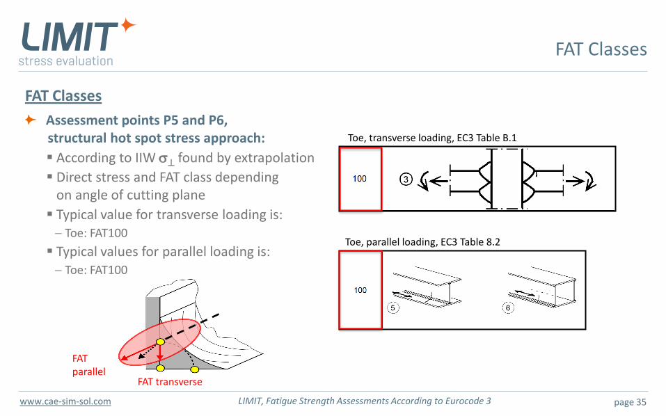
FAT Classes
Assessment points P5 and P6, structural hot spot stress approach:
According to IIW s found by extrapolation
Direct stress and FAT class depending on angle of cutting plane
Typical value for transverse loading is: Toe: FAT100
Typical values for parallel loading is: Toe: FAT100
FAT Classes
Toe, transverse loading, EC3 Table B.1
Toe, parallel loading, EC3 Table 8.2
FAT parallel
FAT transverse
page 36 LIMIT, Fatigue Strength Assessments According to Eurocode 3 www.cae-sim-sol.com
Overview
Fatigue Assessment with LIMIT According to Eurocode 3
Motivation
Stresses and section forces
Stress Spectra
Stress-relieved welded details in compression
FAT classes
S-N curves
Fatigue analysis
Results
page 37 LIMIT, Fatigue Strength Assessments According to Eurocode 3 www.cae-sim-sol.com
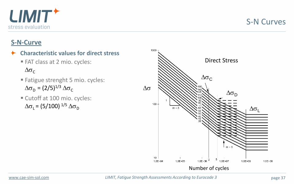
S-N-Curve
Characteristic values for direct stress
FAT class at 2 mio. cycles: DsC
Fatigue strenght 5 mio. cycles: DsD = (2/5)1/3 DsC
Cutoff at 100 mio. cycles: DsL = (5/100) 1/5 DsD
S-N Curves
Ds
DsC
DsD
DsL
Number of cycles
Direct Stress
page 38 LIMIT, Fatigue Strength Assessments According to Eurocode 3 www.cae-sim-sol.com
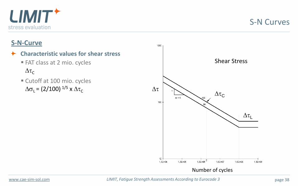
S-N-Curve
Characteristic values for shear stress
FAT class at 2 mio. cycles DtC
Cutoff at 100 mio. cycles DsL = (2/100) 1/5 x DtC
S-N Curves
Dt DtC
DtL
Number of cycles
Shear Stress
page 39 LIMIT, Fatigue Strength Assessments According to Eurocode 3 www.cae-sim-sol.com
Overview
Fatigue Assessment with LIMIT According to Eurocode 3
Motivation
Stresses and section forces
Stress Spectra
Stress-relieved welded details in compression
FAT classes
S-N curves
Fatigue analysis
Results
page 40 LIMIT, Fatigue Strength Assessments According to Eurocode 3 www.cae-sim-sol.com
Proof of Fatigue Strength According to Eurocode 3
Two possibilities for proof
1. Damage criteria
2. Calculation of the equivalent constant amplitude stress range for 2 million cycles
In case of no damage, the actual margin of safety in terms of stress is not clear!
Implementation of the Eurocode 3 in LIMIT
Two modes available
1. Direct damage calculation with damage as the result quantity The stress spectra are taken directly for damage calculation
2. Degree of utilization in terms of stress range A load multiplier LF is calculated
Stress spectra are multiplied by LF
Since the SN-curve may change its shape depending on LF, an iterative procedure is used
Iteration ends when damage is equal or changes from lower 1.0 to values higher than 1.0
Fatigue Analysis
page 41 LIMIT, Fatigue Strength Assessments According to Eurocode 3 www.cae-sim-sol.com
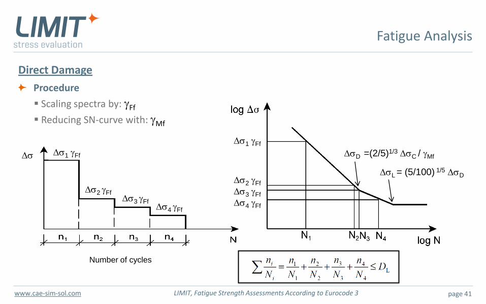
Direct Damage
Procedure
Scaling spectra by: gFf
Reducing SN-curve with: gMf
Fatigue Analysis
Ds1 gFf
Ds2 gFf Ds3 gFf
Number of cycles
Ds4 gFf
Ds
Ds1 gFf
Ds2 gFf
Ds3 gFf
Ds4 gFf
DsD =(2/5)1/3 DsC / gMf
DsL = (5/100) 1/5 DsD
page 42 LIMIT, Fatigue Strength Assessments According to Eurocode 3 www.cae-sim-sol.com
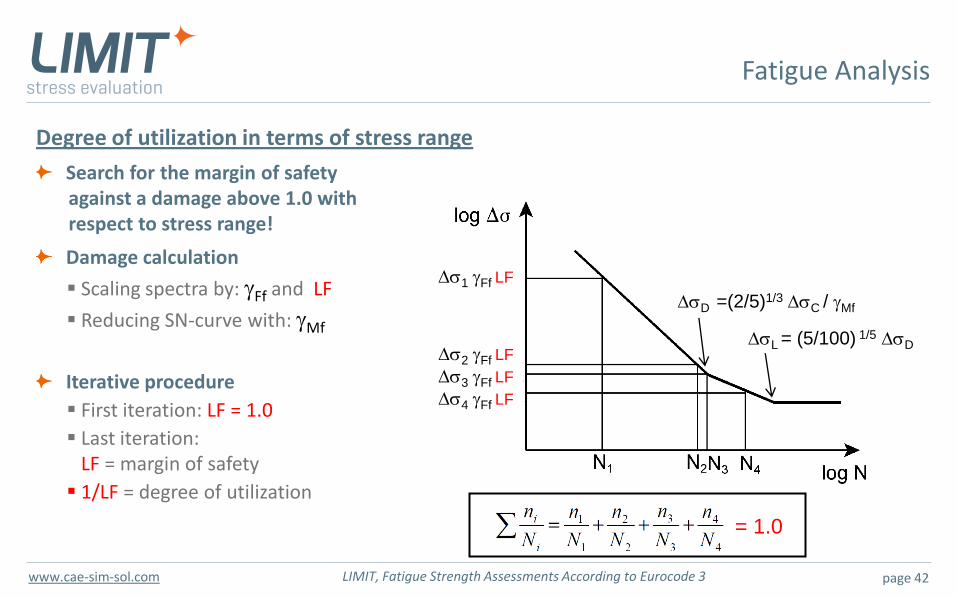
Degree of utilization in terms of stress range
Search for the margin of safety against a damage above 1.0 with respect to stress range!
Damage calculation
Scaling spectra by: gFf and LF
Reducing SN-curve with: gMf
Iterative procedure
First iteration: LF = 1.0
Last iteration: LF = margin of safety
1/LF = degree of utilization
Fatigue Analysis
Ds1 gFf LF
Ds2 gFf LF
Ds3 gFf LF
Ds4 gFf LF
DsD =(2/5)1/3 DsC / gMf
DsL = (5/100) 1/5 DsD
= 1.0
page 43 LIMIT, Fatigue Strength Assessments According to Eurocode 3 www.cae-sim-sol.com
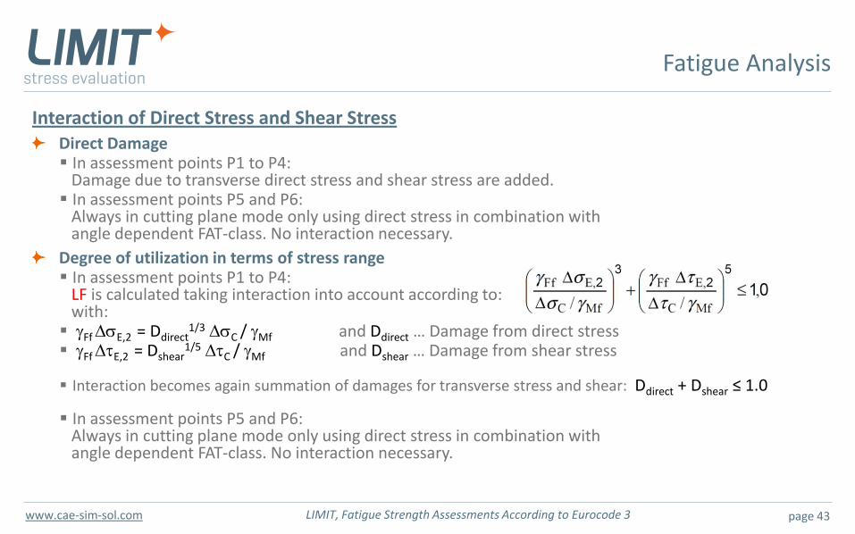
Interaction of Direct Stress and Shear Stress Direct Damage In assessment points P1 to P4: Damage due to transverse direct stress and shear stress are added. In assessment points P5 and P6: Always in cutting plane mode only using direct stress in combination with angle dependent FAT-class. No interaction necessary.
Degree of utilization in terms of stress range In assessment points P1 to P4: LF is calculated taking interaction into account according to: with: gFf DsE,2 = Ddirect
1/3 DsC / gMf and Ddirect … Damage from direct stress
gFf DtE,2 = Dshear1/5 DtC / gMf and Dshear … Damage from shear stress
Interaction becomes again summation of damages for transverse stress and shear: Ddirect + Dshear ≤ 1.0
In assessment points P5 and P6: Always in cutting plane mode only using direct stress in combination with angle dependent FAT-class. No interaction necessary.
Fatigue Analysis
page 44 LIMIT, Fatigue Strength Assessments According to Eurocode 3 www.cae-sim-sol.com
Overview
Fatigue Assessment with LIMIT According to Eurocode 3
Motivation
Stresses and section forces
Stress spectra
Stress-relieved welded details in compression
FAT classes
S-N curves
Fatigue analysis
Results
page 45 LIMIT, Fatigue Strength Assessments According to Eurocode 3 www.cae-sim-sol.com
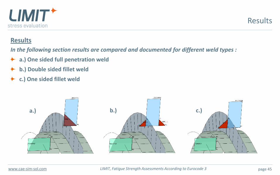
Results
In the following section results are compared and documented for different weld types :
a.) One sided full penetration weld
b.) Double sided fillet weld
c.) One sided fillet weld
Results
a.) b.) c.)
page 46 LIMIT, Fatigue Strength Assessments According to Eurocode 3 www.cae-sim-sol.com
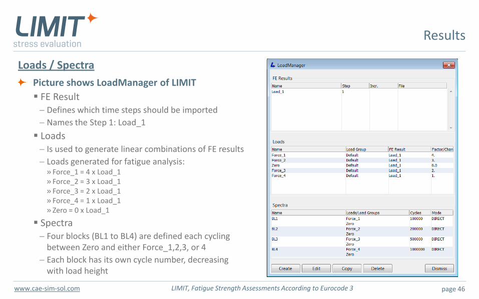
Loads / Spectra
Picture shows LoadManager of LIMIT
FE Result Defines which time steps should be imported
Names the Step 1: Load_1
Loads Is used to generate linear combinations of FE results
Loads generated for fatigue analysis: » Force_1 = 4 x Load_1 » Force_2 = 3 x Load_1 » Force_3 = 2 x Load_1 » Force_4 = 1 x Load_1 » Zero = 0 x Load_1
Spectra Four blocks (BL1 to BL4) are defined each cycling
between Zero and either Force_1,2,3, or 4
Each block has its own cycle number, decreasing with load height
Results
page 47 LIMIT, Fatigue Strength Assessments According to Eurocode 3 www.cae-sim-sol.com
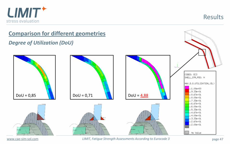
Comparison for different geometries
Degree of Utilization (DoU)
Results
DoU = 4,88 DoU = 0,71 DoU = 0,85
page 48 LIMIT, Fatigue Strength Assessments According to Eurocode 3 www.cae-sim-sol.com
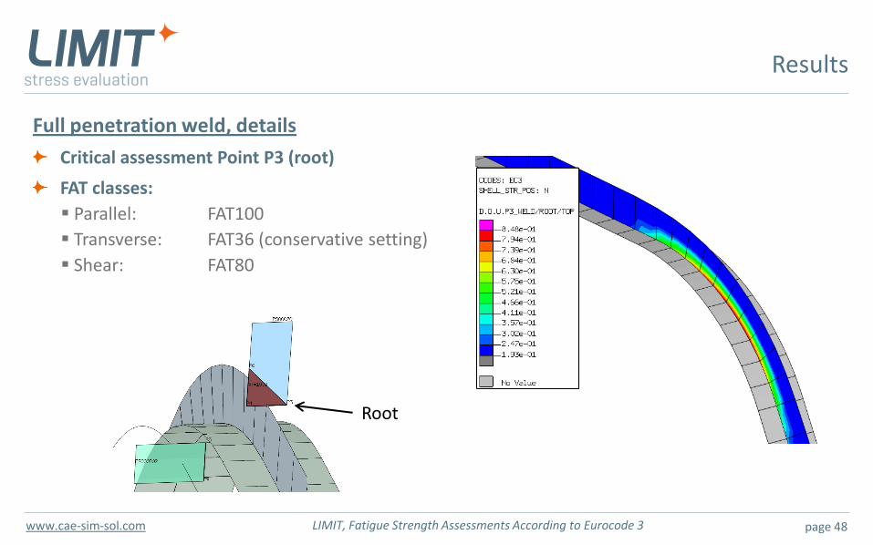
Full penetration weld, details
Critical assessment Point P3 (root)
FAT classes:
Parallel: FAT100
Transverse: FAT36 (conservative setting)
Shear: FAT80
Results
Root

page 49 LIMIT, Fatigue Strength Assessments According to Eurocode 3 www.cae-sim-sol.com
Results: Full penetration weld: LIMIT Text output
no damage for shear at LF = 1
damage for direct stress at LF = 1
no damage for shear at LF = 1.17
damage = 1 for direct stress at LF = 1.17
DoU = 0.85
EC3-VALUES:
Rp02 = 235.000 , Yield stress
gff = 1.00000 , Partial safety factor fatigue load
gfm = 1.00000 , Partial safety factor fatigue strength
FAT-VALUES (2 Mio Cycles):
DSCL = 100.000 , 1. direction resp. parallel to weld
DSCQ = 36.0000 , 2. direction resp. lateral to weld
DSCS = 80.0000 , Shear in weld section
FAT-VALUES (2 Mio Cycles) / gfm :
DSCL = 100.000 , 1. direction resp. parallel to weld
DSCQ = 36.0000 , 2. direction resp. lateral to weld
DSCS = 80.0000 , Shear in weld section
DIMENSIONS:
t = 10.0000 , Sheet thickness
au = 0.00000 , A-dimension, shell bottom side
ao = 10.0000 , A-dimension, shell top side
dau = 0.00000 , Root position, shell bottom side
dao = -5.00000 , Root position, shell top side
IEX = 2, Exzentricity: constrained (50%)
ALFA = 0.00000 , Angle between cutting plane and weld
(only valid for weld toes: Positions 5 and 6)
SPECTRUM DATA:
BLOCK: 1, PER ROW ONE STRESS COMPONENT (11,22,33,12)
COMP., STRESS RANGE, MEAN STRESS, CYCLES, RELEVANT LOAD CASES)
S11 76.284 38.142 0.10000E+06 1 2
S22 60.824 30.412 0.10000E+06 1 2
S33 0.0000 0.0000 0.0000 0 0
S12 13.200 6.6000 0.10000E+06 1 2
BLOCK: 2, PER ROW ONE STRESS COMPONENT (11,22,33,12)
COMP., STRESS RANGE, MEAN STRESS, CYCLES, RELEVANT LOAD CASES)
S11 57.213 28.607 0.20000E+06 3 2
S22 45.618 22.809 0.20000E+06 3 2
S33 0.0000 0.0000 0.0000 0 0
S12 9.9000 4.9500 0.20000E+06 3 2
BLOCK: 3, PER ROW ONE STRESS COMPONENT (11,22,33,12)
COMP., STRESS RANGE, MEAN STRESS, CYCLES, RELEVANT LOAD CASES)
S11 38.142 19.071 0.50000E+06 4 2
S22 30.412 15.206 0.50000E+06 4 2
S33 0.0000 0.0000 0.0000 0 0
S12 6.6000 3.3000 0.50000E+06 4 2
BLOCK: 4, PER ROW ONE STRESS COMPONENT (11,22,33,12)
COMP., STRESS RANGE, MEAN STRESS, CYCLES, RELEVANT LOAD CASES)
S11 19.071 9.5355 0.10000E+07 5 2
S22 15.206 7.6029 0.10000E+07 5 2
S33 0.0000 0.0000 0.0000 0 0
S12 3.3000 1.6500 0.10000E+07 5 2
FATIGUE STRENGTH and CUTOFF:
DSDQ = 26.5320 , Fatigue strength, lateral to weld direction
DSLQ = 14.5735 , Cutoff lateral to weld direction
DSLT = 36.5600 , Cutoff shear
------------------------------------------------
RESULT OF FIRST ITERATION: LF=1
DST ... SHEAR STRESS WELD SECTION
STEP DST*gff DST*gff*LF N_D=1 N_given DAM
1 13.200 13.200 0.10000E+06
2 9.9000 9.9000 0.20000E+06
3 6.6000 6.6000 0.50000E+06
4 3.3000 3.3000 0.10000E+07
DSQ ... STRESS IN WELD SECTION (LATERAL)
DAMAGE AT DSQ*gff*LF:
STEP DSQ*gff DSQ*gff*LF N_D=1 N_given DAM
1 60.824 60.824 0.41469E+06 0.10000E+06 0.24114
2 45.618 45.618 0.98297E+06 0.20000E+06 0.20347
3 30.412 30.412 0.33175E+07 0.50000E+06 0.15072
4 15.206 15.206 0.80865E+08 0.10000E+07 0.12366E-01
------------------------------------------------
RESULT OF LAST ITERATION: LF= 1.17859
(STRESS RANGES ARE MULTIPLIED WITH MARGIN OF SAFETY)
DAMAGE AT DST*gff*LF:
STEP DST*gff DST*gff*LF N_D=1 N_given DAM
1 13.200 15.557 0.10000E+06
2 9.9000 11.668 0.20000E+06
3 6.6000 7.7787 0.50000E+06
4 3.3000 3.8893 0.10000E+07
DAMAGE EQUIVALENT STRESS RANGE:
DSTEQ2 = 0.00000 , Damage equivalent range DS, 2 mio cycles
DAMAGE AT DSQ*gff*LF:
1 60.824 71.686 0.25330E+06 0.10000E+06 0.39479
2 45.618 53.764 0.60041E+06 0.20000E+06 0.33310
3 30.412 35.843 0.20264E+07 0.50000E+06 0.24674
4 15.206 17.921 0.35559E+08 0.10000E+07 0.28122E-01
DAMAGE EQUIVALENT STRESS RANGE:
DSQEQ2 = 36.0331 , Damage equivalent range DS, 2 mio cycles
------------------------------------------------
DEGREE OF UTILIZATION (INVERSE MARGIN OF SAFETY)
ALGQ = 0.848472 , Degree of utilization lateral to weld
ALGQPL = 0.172549 , Degree of utilization lateral to weld, yielding
ALGT = 0.848472E-06, Degree of utilization shear
ALGTPL = 0.648595E-01, Degree of utilization shear, yielding
ALGKMB = 0.848472 , Combined degree of utilization
page 50 LIMIT, Fatigue Strength Assessments According to Eurocode 3 www.cae-sim-sol.com
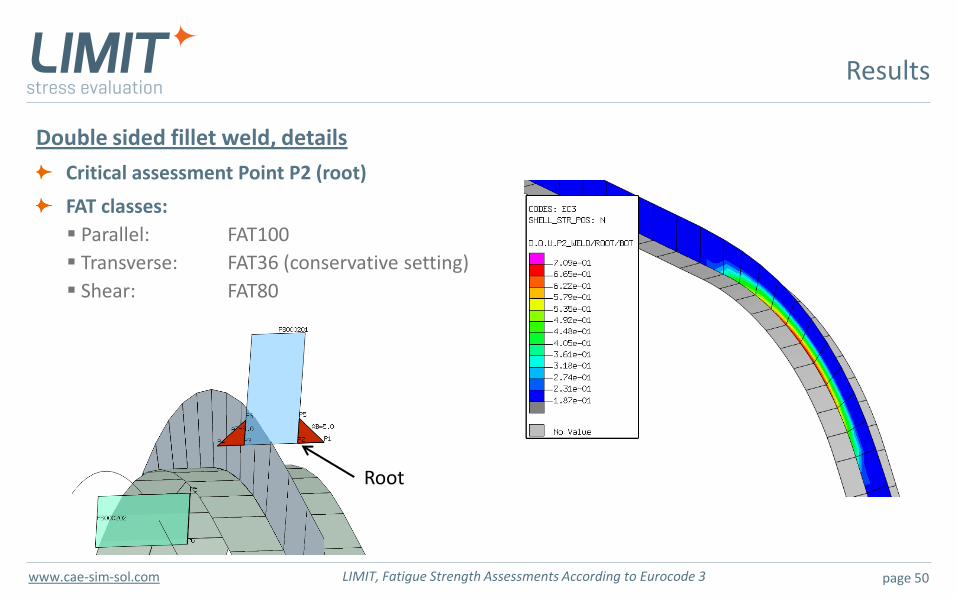
Double sided fillet weld, details
Critical assessment Point P2 (root)
FAT classes:
Parallel: FAT100
Transverse: FAT36 (conservative setting)
Shear: FAT80
Results
Root
page 51 LIMIT, Fatigue Strength Assessments According to Eurocode 3 www.cae-sim-sol.com
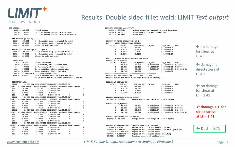
Results: Double sided fillet weld: LIMIT Text output
no damage for shear at LF = 1
damage for direct stress at LF = 1
no damage for shear at LF = 1.41
damage = 1 for direct stress at LF = 1.41
DoU = 0.71
EC3-VALUES:
Rp02 = 235.000 , Yield stress
gff = 1.00000 , Partial safety factor fatigue load
gfm = 1.00000 , Partial safety factor fatigue strength
FAT-VALUES (2 Mio Cycles):
DSCL = 100.000 , 1. direction resp. parallel to weld
DSCQ = 36.0000 , 2. direction resp. lateral to weld
DSCS = 80.0000 , Shear in weld section
FAT-VALUES (2 Mio Cycles) / gfm :
DSCL = 100.000 , 1. direction resp. parallel to weld
DSCQ = 36.0000 , 2. direction resp. lateral to weld
DSCS = 80.0000 , Shear in weld section
DIMENSIONS:
t = 10.0000 , Sheet thickness
au = 5.00000 , A-dimension, shell bottom side
ao = 5.00000 , A-dimension, shell top side
dau = 5.00000 , Root position, shell bottom side
dao = 5.00000 , Root position, shell top side
IEX = 2, Exzentricity: constrained (50%)
ALFA = 0.00000 , Angle between cutting plane and weld
(only valid for weld toes: Positions 5 and 6)
SPECTRUM DATA:
BLOCK: 1, PER ROW ONE STRESS COMPONENT (11,22,33,12)
COMP., STRESS RANGE, MEAN STRESS, CYCLES, RELEVANT LOAD CASES)
S11 76.284 38.142 0.10000E+06 1 2
S22 50.830 25.415 0.10000E+06 1 2
S33 0.0000 0.0000 0.0000 1 2
S12 13.243 6.6217 0.10000E+06 1 2
BLOCK: 2, PER ROW ONE STRESS COMPONENT (11,22,33,12)
COMP., STRESS RANGE, MEAN STRESS, CYCLES, RELEVANT LOAD CASES)
S11 57.213 28.607 0.20000E+06 3 2
S22 38.123 19.061 0.20000E+06 3 2
S33 0.0000 0.0000 0.0000 0 0
S12 9.9326 4.9663 0.20000E+06 3 2
BLOCK: 3, PER ROW ONE STRESS COMPONENT (11,22,33,12)
COMP., STRESS RANGE, MEAN STRESS, CYCLES, RELEVANT LOAD CASES)
S11 38.142 19.071 0.50000E+06 4 2
S22 25.415 12.708 0.50000E+06 4 2
S33 0.0000 0.0000 0.0000 0 0
S12 6.6217 3.3109 0.50000E+06 4 2
BLOCK: 4, PER ROW ONE STRESS COMPONENT (11,22,33,12)
COMP., STRESS RANGE, MEAN STRESS, CYCLES, RELEVANT LOAD CASES)
S11 19.071 9.5355 0.10000E+07 5 2
S22 12.708 6.3538 0.10000E+07 5 2
S33 0.0000 0.0000 0.0000 0 0
S12 3.3109 1.6554 0.10000E+07 5 2
FATIGUE STRENGTH and CUTOFF:
DSDQ = 26.5320 , Fatigue strength, lateral to weld direction
DSLQ = 14.5735 , Cutoff lateral to weld direction
DSLT = 36.5600 , Cutoff shear
------------------------------------------------
RESULT OF FIRST ITERATION: LF=1
DST ... SHEAR STRESS WELD SECTION
STEP DST*gff DST*gff*LF N_D=1 N_given DAM
1 13.243 13.243 0.10000E+06
2 9.9326 9.9326 0.20000E+06
3 6.6217 6.6217 0.50000E+06
4 3.3109 3.3109 0.10000E+07
DSQ ... STRESS IN WELD SECTION (LATERAL)
DAMAGE AT DSQ*gff*LF:
STEP DSQ*gff DSQ*gff*LF N_D=1 N_given DAM
1 50.830 50.830 0.71051E+06 0.10000E+06 0.14074
2 38.123 38.123 0.16842E+07 0.20000E+06 0.11875
3 25.415 25.415 0.61994E+07 0.50000E+06 0.80652E-01
4 12.708 12.708 0.10000E+07
------------------------------------------------
RESULT OF LAST ITERATION: LF= 1.41052
(STRESS RANGES ARE MULTIPLIED WITH MARGIN OF SAFETY)
DAMAGE AT DST*gff*LF:
STEP DST*gff DST*gff*LF N_D=1 N_given DAM
1 13.243 18.680 0.10000E+06
2 9.9326 14.010 0.20000E+06
3 6.6217 9.3401 0.50000E+06
4 3.3109 4.6700 0.10000E+07
DAMAGE EQUIVALENT STRESS RANGE:
DSTEQ2 = 0.00000 , Damage equivalent range DS, 2 mio cycles
DAMAGE AT DSQ*gff*LF:
1 50.830 71.697 0.25318E+06 0.10000E+06 0.39498
2 38.123 53.773 0.60013E+06 0.20000E+06 0.33326
3 25.415 35.849 0.20254E+07 0.50000E+06 0.24686
4 12.708 17.924 0.35531E+08 0.10000E+07 0.28145E-01
DAMAGE EQUIVALENT STRESS RANGE:
DSQEQ2 = 36.0389 , Damage equivalent range DS, 2 mio cycles
------------------------------------------------
DEGREE OF UTILIZATION (INVERSE MARGIN OF SAFETY)
ALGQ = 0.708957 , Degree of utilization lateral to weld
ALGQPL = 0.144200 , Degree of utilization lateral to weld, yielding
ALGT = 0.708957E-06, Degree of utilization shear
ALGTPL = 0.650730E-01, Degree of utilization shear, yielding
ALGKMB = 0.708957 , Combined degree of utilization
page 52 LIMIT, Fatigue Strength Assessments According to Eurocode 3 www.cae-sim-sol.com
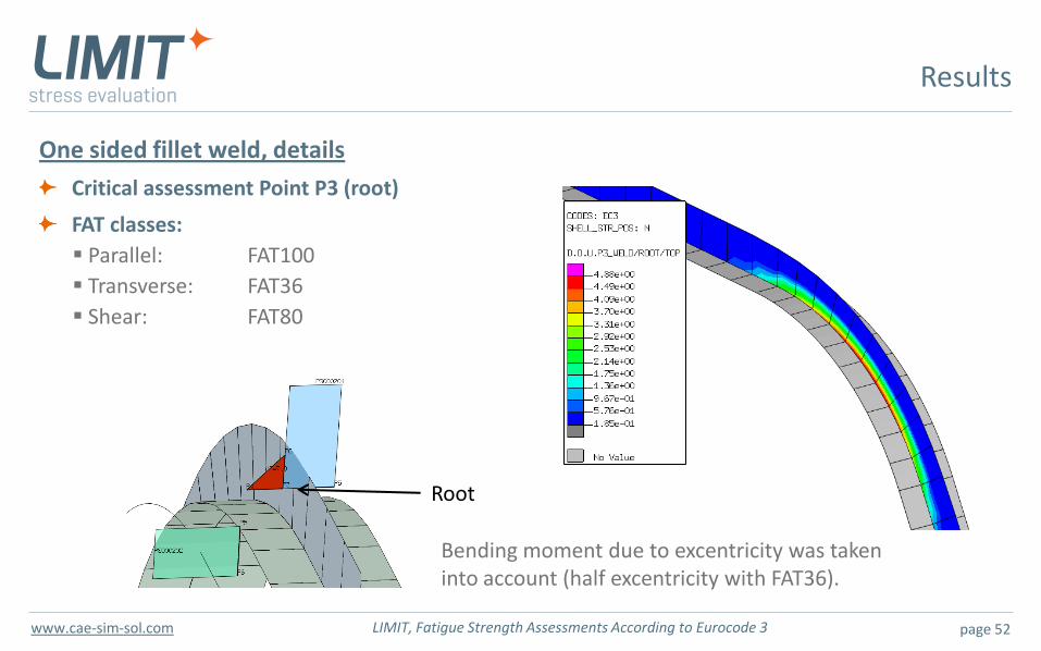
One sided fillet weld, details
Critical assessment Point P3 (root)
FAT classes:
Parallel: FAT100
Transverse: FAT36
Shear: FAT80
Results
Root
Bending moment due to excentricity was taken into account (half excentricity with FAT36).
page 53 LIMIT, Fatigue Strength Assessments According to Eurocode 3 www.cae-sim-sol.com
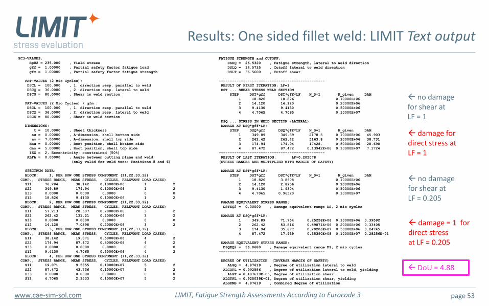
Results: One sided fillet weld: LIMIT Text output
no damage for shear at LF = 1
damage for direct stress at LF = 1
no damage for shear at LF = 0.205
damage = 1 for direct stress at LF = 0.205
DoU = 4.88
EC3-VALUES:
Rp02 = 235.000 , Yield stress
gff = 1.00000 , Partial safety factor fatigue load
gfm = 1.00000 , Partial safety factor fatigue strength
FAT-VALUES (2 Mio Cycles):
DSCL = 100.000 , 1. direction resp. parallel to weld
DSCQ = 36.0000 , 2. direction resp. lateral to weld
DSCS = 80.0000 , Shear in weld section
FAT-VALUES (2 Mio Cycles) / gfm :
DSCL = 100.000 , 1. direction resp. parallel to weld
DSCQ = 36.0000 , 2. direction resp. lateral to weld
DSCS = 80.0000 , Shear in weld section
DIMENSIONS:
t = 10.0000 , Sheet thickness
au = 0.00000 , A-dimension, shell bottom side
ao = 7.00000 , A-dimension, shell top side
dau = 0.00000 , Root position, shell bottom side
dao = 5.00000 , Root position, shell top side
IEX = 2, Exzentricity: constrained (50%)
ALFA = 0.00000 , Angle between cutting plane and weld
(only valid for weld toes: Positions 5 and 6)
SPECTRUM DATA:
BLOCK: 1, PER ROW ONE STRESS COMPONENT (11,22,33,12)
COMP., STRESS RANGE, MEAN STRESS, CYCLES, RELEVANT LOAD CASES)
S11 76.284 38.142 0.10000E+06 1 2
S22 349.89 174.94 0.10000E+06 1 2
S33 0.0000 0.0000 0.0000 0 0
S12 18.826 9.4130 0.10000E+06 1 2
BLOCK: 2, PER ROW ONE STRESS COMPONENT (11,22,33,12)
COMP., STRESS RANGE, MEAN STRESS, CYCLES, RELEVANT LOAD CASES)
S11 57.213 28.607 0.20000E+06 3 2
S22 262.42 131.21 0.20000E+06 3 2
S33 0.0000 0.0000 0.0000 0 0
S12 14.120 7.0598 0.20000E+06 3 2
BLOCK: 3, PER ROW ONE STRESS COMPONENT (11,22,33,12)
COMP., STRESS RANGE, MEAN STRESS, CYCLES, RELEVANT LOAD CASES)
S11 38.142 19.071 0.50000E+06 4 2
S22 174.94 87.472 0.50000E+06 4 2
S33 0.0000 0.0000 0.0000 0 0
S12 9.4130 4.7065 0.50000E+06 4 2
BLOCK: 4, PER ROW ONE STRESS COMPONENT (11,22,33,12)
COMP., STRESS RANGE, MEAN STRESS, CYCLES, RELEVANT LOAD CASES)
S11 19.071 9.5355 0.10000E+07 5 2
S22 87.472 43.736 0.10000E+07 5 2
S33 0.0000 0.0000 0.0000 0 0
S12 4.7065 2.3533 0.10000E+07 5 2
FATIGUE STRENGTH and CUTOFF:
DSDQ = 26.5320 , Fatigue strength, lateral to weld direction
DSLQ = 14.5735 , Cutoff lateral to weld direction
DSLT = 36.5600 , Cutoff shear
------------------------------------------------
RESULT OF FIRST ITERATION: LF=1
DST ... SHEAR STRESS WELD SECTION
STEP DST*gff DST*gff*LF N_D=1 N_given DAM
1 18.826 18.826 0.10000E+06
2 14.120 14.120 0.20000E+06
3 9.4130 9.4130 0.50000E+06
4 4.7065 4.7065 0.10000E+07
DSQ ... STRESS IN WELD SECTION (LATERAL)
DAMAGE AT DSQ*gff*LF:
STEP DSQ*gff DSQ*gff*LF N_D=1 N_given DAM
1 349.89 349.89 2178.5 0.10000E+06 45.903
2 262.42 262.42 5163.8 0.20000E+06 38.731
3 174.94 174.94 17428. 0.50000E+06 28.690
4 87.472 87.472 0.13942E+06 0.10000E+07 7.1724
------------------------------------------------
RESULT OF LAST ITERATION: LF=0.205078
(STRESS RANGES ARE MULTIPLIED WITH MARGIN OF SAFETY)
DAMAGE AT DST*gff*LF:
STEP DST*gff DST*gff*LF N_D=1 N_given DAM
1 18.826 3.8608 0.10000E+06
2 14.120 2.8956 0.20000E+06
3 9.4130 1.9304 0.50000E+06
4 4.7065 0.96520 0.10000E+07
DAMAGE EQUIVALENT STRESS RANGE:
DSTEQ2 = 0.00000 , Damage equivalent range DS, 2 mio cycles
DAMAGE AT DSQ*gff*LF:
1 349.89 71.754 0.25258E+06 0.10000E+06 0.39592
2 262.42 53.816 0.59871E+06 0.20000E+06 0.33405
3 174.94 35.877 0.20206E+07 0.50000E+06 0.24745
4 87.472 17.939 0.35390E+08 0.10000E+07 0.28256E-01
DAMAGE EQUIVALENT STRESS RANGE:
DSQEQ2 = 36.0680 , Damage equivalent range DS, 2 mio cycles
------------------------------------------------
DEGREE OF UTILIZATION (INVERSE MARGIN OF SAFETY)
ALGQ = 4.87619 , Degree of utilization lateral to weld
ALGQPL = 0.992586 , Degree of utilization lateral to weld, yielding
ALGT = 0.487619E-05, Degree of utilization shear
ALGTPL = 0.925039E-01, Degree of utilization shear, yielding
ALGKMB = 4.87619 , Combined degree of utilization
page 54 LIMIT, Fatigue Strength Assessments According to Eurocode 3 www.cae-sim-sol.com
Last slide!
End


![Forces and Stresses on Ships [Compatibility Mode]](https://img.pdfslide.us/doc/110x75/547f0aff5806b5bd5e8b476c/forces-and-stresses-on-ships-compatibility-mode.jpg)