Embed Size (px)
Citation preview
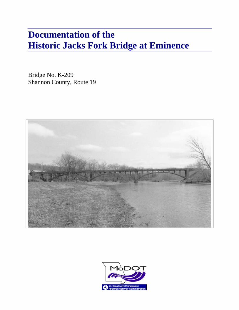
Documentation of the Historic Jacks Fork Bridge at Eminence Bridge No. K-209 Shannon County, Route 19

This page intentionally left blank for printing purposes
Eminence Bridge (Jacks Fork Bridge) Bridge No. K-209
Shannon County, Route 19
David C. Austin, Historian August 2002
Historical Narrative The Eminence Bridge spans the Jacks Fork River at Missouri Route 19 at Eminence, Shannon County. The bridge is a three-span, reinforced concrete, two-rib open spandrel arch structure with reinforced concrete deck girder approach spans and reinforced concrete abutments and piers. The bridge is a well-preserved example of open spandrel arch construction employed by the Missouri State Highway Department during the 1920s and early 1930s.1
Route 19 had been mandated by the 1921 Centennial Road Law to link Eminence, the county seat of Shannon County, with the adjacent county seats of Salem, Dent County, and Alton, Oregon County.2 Within Shannon County, work on the highway proceeded in stages beginning in the early 1920s. Crossing Jacks Fork at Eminence, Route 19 initially utilized a single-span Parker through truss bridge built in 1918-1919 by the Shannon County Court for $14,775. The state highway department had provided $1,000 toward a wood approach at the north end of the bridge. The county spent another $12,000 to cut through a rock bluff at the south end of the bridge. Having incorporated the steel bridge into the state highway system, the highway department refloored the structure in 1926.3 One of the first state highway projects in Shannon County, completed in 1923, involved 4.26 miles of a 24-foot wide graded earth road leading south from the Eminence courthouse. In 1928, another Route 19 project provided 2.4 miles of a 30-foot wide graded earth road north of Jacks Fork. The highway department meanwhile constructed a reinforced concrete filled spandrel arch bridge over the upper Current River and a reinforced concrete open spandrel arch bridge over Sinking Creek, both in northern Shannon County. Nearby, the department erected a skewed open spandrel arch bridge over Spring Valley Creek near Round Spring in 1930. The highway department had realized that the area’s natural supplies of sand and gravel provided an economical source of concrete aggregate. “It is generally recognized that southern Missouri has an abundant supply of good road materials. All through the Ozark territory, the streams are filled with a good grade of road gravel and in
1 Clayton B. Fraser, “HAER Inventory Data Sheet, Eminence Bridge (Jacks Fork Bridge), SHAN04,” Missouri Historic Bridge Inventory, (Draft), 5 Vols., Missouri Department of Transportation, Project No. NBIH (6) (Loveland Colorado: Fraserdesign, Inc., 1996). 2 Missouri State Highway Commission, Third Biennial Report of the State Highway Commission of Missouri for the Period Ending December 1, 1922 (Jefferson City: Hugh Stephens Company, Printers), 41-55. 3 Louis V. Stigall, Chief Counsel, to L. B. Shuck, Shannon County Prosecuting Attorney, January 18, 1938, in Bridge K-209 Project File, Bridge Division, Missouri Department of Transportation, Jefferson City.
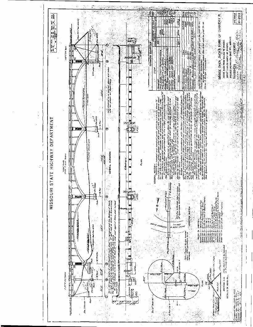
many cases a quality of gravel suitable for concrete work.”4 By 1930, most of Route 19 in Shannon County consisted of either a newly-graded earth road awaiting a gravel surface, or a state-maintained, all-weather road still needing modern improvements.5 The state highway department began planning for a new bridge over Jacks Fork in late 1932. Although the existing bridge built by Shannon County was only a dozen years old, it apparently was inadequate by modern standards and had received load-limit restrictions. A new bridge would link into the adjacent sections of Route 19 already completed, and cross the river on a relatively straight alignment compared to the existing location one-quarter mile upstream from Eminence. In December 1932 and April 1933, the department made extensive soundings of the Jacks Fork river bed, boring through layers of sand, gravel, clay and rock to determine the depths to solid limestone bedrock. The department’s bridge engineers drew, traced and checked construction plans for the new crossing from March through July 1933. The Bridge Engineer N. R. Sack and Chief Engineer Thomas H. Cutler signed off on the bridge design on August 8. The bridge project, designated NRH-379A, received federal funding under the National Industrial Recovery Act (NIRA) enacted in June 1933. The project included roadway approaches at each end of the bridge to total just over three-quarters of a mile in length. Letting of the construction contract on October 28, 1933, drew bids from twelve firms. The List and Clark Construction Company of Kansas City submitted the low bid of $69,137.6
Soon after receiving the contract, the List and Clark Construction Company began shipping their machinery and equipment by railroad to Winona, then hauled it the remaining ten miles north to Eminence. W. F. Mason arrived as the project superintendent for List and Clark, while W. R. Wallace would oversee the work for the highway department. Federal provisions under NIRA required the use of local labor as far as possible, with minimum wages of 35 cents an hour for unskilled labor and 50 cents an hour for skilled labor. Work on the Eminence Bridge began around November 13. Mason first began the excavations for Pier 6 and Bent 7 on the south bank, pouring the concrete footings on December 3. That evening, water erupted through bedrock fissures into the left footing of Pier 6 and completely flooded its cofferdam, ruining the
4 Route 19, Shannon County, Construction History [map], Plans and Records Office, Design Division, Missouri Department of Transportation, Jefferson City; Fraser, “HAER Inventory Data Sheet, Current River Bridge, SHAN01,” “HAER Inventory Data Sheet, Sinking Creek Bridge, SHAN02,” and HAER Inventory Data Sheet, Round Spring Bridge, SHAN03,” in Missouri Historic Bridge Inventory; Missouri State Highway Commission, Fourth Biennial Report of the State Highway Commission of Missouri for the Period Ending December 1, 1924 (Jefferson City: Hugh Stephens Press, 1924), 64. 5 Missouri State Highway Commission, “Map of Missouri Showing State Road System, Route Numbers, Road Conditions, and Points of Interest," (Jefferson City: Botz-Hugh Stephens Press, 1930). 6 Current Wave (Eminence), November 16, 1933; “Log of Soundings,” December 3, 1932 and April 10, 14 and 19, 1933, in Bridge K-209 Project File; Missouri State Highway Department, “Bridge Over Jack’s Fork of Current River,” Bridge No. K-209 design plans [eleven sheets], August 18, 1933, Bridge Division, Missouri Department of Transportation, Jefferson City; Missouri State Highway Commission, “Plan and Profile of Proposed State Road,” Route 19, Shannon County, Project 19-NRH-379A, Plans and Records Office, Design Division, Missouri Department of Transportation, Jefferson City; “Tabulation of Bids Received,” Shannon County, Route 19, Project NRH-379A, October 28, 1933, Plans and Records Office, Design Division, Missouri Department of Transportation, Jefferson City.
freshly-poured concrete and suspending the work there for several days. Worse misfortune followed on December 8, when one of the workers, Frank Dixon, suffered fatal injuries at the project’s gravel plant. A cable on a hoisting gin snapped, and a heavy gin pole fell on Dixon. He sustained a skull fracture, internal injuries, and back injuries. Dixon was taken to a hospital in West Plains where he died on December 12. Dixon was a lifelong resident of Shannon County and left a wife and several children.7
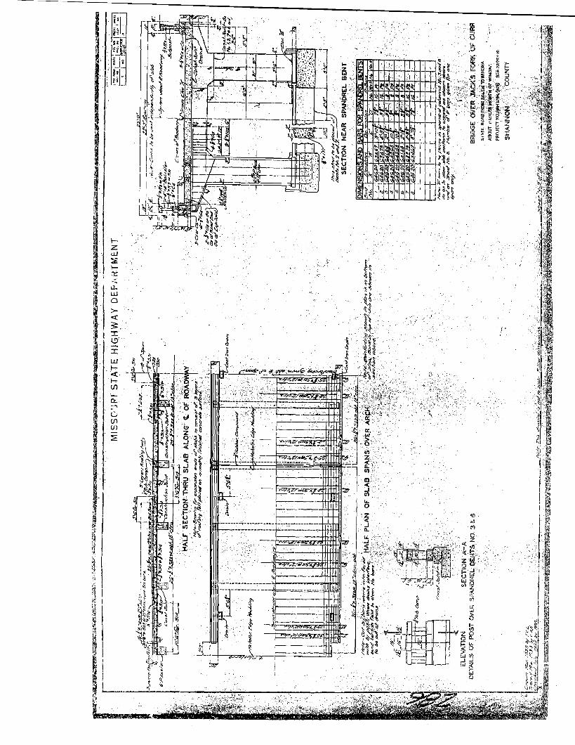
After this inauspicious beginning, the bridge construction proceeded relatively smoothly. Construction of Pier 6 resumed on December 14, while pouring of Pier 3 on the opposite bank began by December 18. On February 1, 1934, the Current Wave newspaper of Eminence reported that two piers (presumably Pier 6 and Bent 7) were “practically complete” and two others on the north bank (including Pier 3) were partially built. Pouring of the footings for Pier 5 began in mid-February. All of the fine aggregate and course aggregate used in the concrete came from the Jacks Fork River. Steam heat was used to maintain the temperature of the concrete during the curing process. Pouring of the arch ribs for the three arch spans occurred during March 1934, beginning with Span 3 (the northern span) on March 1. This was followed by the ribs for Span 4 on March 8, and the final key sections of Span 5 (the southern arch span) on March 27. Specifications called for a richer mix of a quick-hardening cement to be used in the arch ribs. The two ribs on a given span were poured simultaneously in four segments to equalize the stresses on the falsework centering that temporarily supported the structure. The first blocks poured were from the construction joints at the spring line outward approximately 15’; next, block two was a 21’ section of the arch crown; then block three, two 20’ sections left and right of the arch crown; finally, two 4’-0” key sections at the ends of the latter blocks to close the arch. Pouring the final key sections occurred at least twenty-four hours after the adjacent blocks had been poured. Pouring of the pilasters, the spandrel bents, the bridge deck and the balustrades completed the structure. While the bridge itself was finished before the end of May, more work remained in the construction of the roadway approaches.8 Constructing the adjoining sections of Route 19 involved the grading of about 2,500’ of roadbed north of the bridge, with about 1,100’ on a new alignment. On the south side of the bridge, the end abutment, Bent 7, was enclosed by approximately 3,100 cubic yards of rock fill built up 21’ high to the bent’s bridge seat. Running south into Eminence, the new highway required a 700’-long earth fill approach about 20’ high, and the grading down of a small hill in north Eminence for a distance of about 500’. List and Clark used a steam shovel in the excavation of the road cut in north Eminence, and hauled the fill in dump trucks to build up the south approach. More roadway fill material came from leveling the floodplain beneath the arch
7 Shannon County Democrat (Winona), November 16, 1933; Current Wave, October 19, November 16, December 7, 14, 1933; “Report of Tests on Concrete Cylinders,” January 3, 1934; Chief Engineer to S. W. O’Brien, Senior Highway Engineer, Bureau of Public Roads, July 17, 1934, in Bridge K-209 Project File. 8 Current Wave, February 1, May 24, 1934; “Report of Tests on Concrete Cylinders,” passim; W. F. Mason, List and Clark Construction Company, to N. R. Sack, Bridge Engineer, January 3, 1934; N. R. Sack, Bridge Engineer, to List and Clark Construction Company, January 10, 1934, in Bridge K-209 Project File.
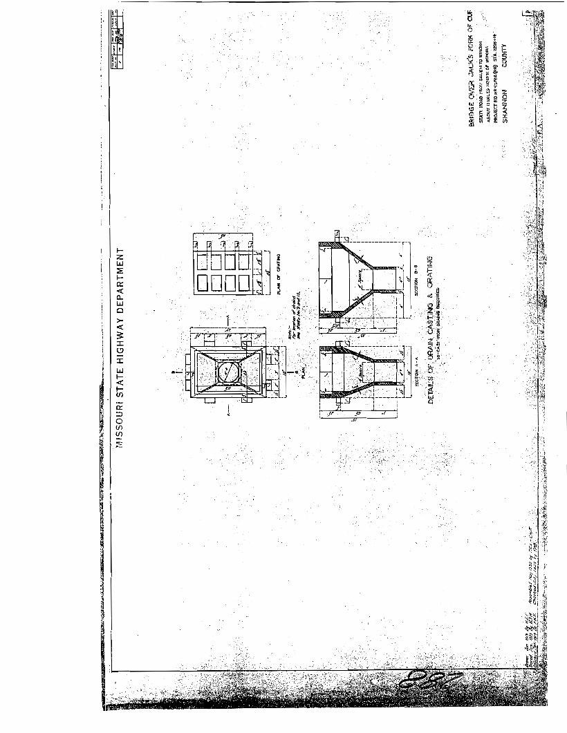
spans for over 200’ both up and downstream. This left the surface of the floodplain just below the spring line of the arches and improved the channel overflow.9 While this work on the approaches continued through June, the citizens of Eminence made plans to dedicate the new bridge in conjunction with their Fourth of July celebration. The two-day festivities on July 3 and 4 included a picnic, a carnival, a “colored minstrel show,” baseball games and an “old fiddlers” contest, but apparently the community leaders dropped the idea of the bridge dedication at the last minute. At least the Current Wave made no mention of it. Work on the approaches continued into late July. With the south approach finally complete, List and Clark had about one day’s work to finish the north approach when their steam shovel broke down. Travelers meanwhile began using the new bridge, but had to take a detour along the north river bank and tie into the old section of highway. State and federal highway officials were able to conduct an inspection of the completed bridge project on July 25, 1934.10 In a subsequent inspection report, Mr. S. E. Sime of the Bureau of Public Roads detailed a number of deficiencies he saw with the structure, and recommended on those grounds that federal funding be withdrawn from the project. Protesting Sime’s recommendation, Chief Engineer Cutler conceded that some “minor details” did not meet construction standards but insisted that the bridge was “structurally sound” and that the deficiencies could be corrected.11 On August 21, representatives of the Missouri State Highway Department (including the project engineer W. R. Wallace; D. C. Wolfe of the Bridge Department; General Inspector O. D. Chrisman; Division Engineer of Division No. 9 Harry D. Griffith; and Division Construction Engineer J. E. Carlson) met at the bridge site with Sime of the Bureau of Public Roads and W. F. Mason of List and Clark. After another inspection, the men determined what work would be required to put the bridge in an acceptable condition. Mason’s crew would have to remove and rebuild the balustrades along the entire structure; fill holes in the concrete caps and girders caused by the bolts from the falsework; rub down all of the concrete to a uniform finish, including the tops and sides of the arch ribs; and address “any other problems that need correction in order to comply with the specifications and plans.” In addition, while Mason had already removed the old steel truss bridge, he had neglected to remove its north pier as required. Mason indicated he would resume the work immediately, but the project remained at a standstill for several more weeks. On September 15, Division Engineer Harry Griffith reminded the List and Clark Construction Company that they would be assessed liquidated damages if they went beyond the contracted completion date. Griffith also warned that if the company did not recommence the work within ten days, the highway department would consider them in default on the construction contract, and would call on their surety company to finish the job.12
9 Missouri State Highway Department, “Bridge Over Jack’s Fork,” Bridge K-209 Design Plans; Missouri State Highway Commission, Route 19, Shannon County, Project 19-NRH-379A, Design Plans. 10 Current Wave, June 7, 14, 28, July 5, 19, 1934. 11 Sime’s inspection report was not found in the Bridge K-209 project files. Chief Engineer [T. H. Cutler] to S. W. O’Brien, Senior Highway Engineer, Bureau of Public Roads, August 7, 1934, in Bridge K-209 Project File. 12 Harry D. Griffith, Division Engineer, to List and Clark Construction Company, September 14, 1934, in Bridge K-209 Project File.
There are no additional records in the Bridge K-209 project files concerning this corrective work required of List and Clark. The Current Wave of Eminence made no mention of any continuing construction on the bridge. Presumably, however, List and Clark did complete the necessary corrections instead of defaulting on their contract. Ultimately, engineers from the Division No. 9 office at Willow Springs made a final inspection and accepted the project on February 13, 1935. The Current Wave, in briefly noting the completion of the Eminence Bridge, stated, “This is one of the finest bridges in this part of the state and the people of Eminence, as well as of Shannon County, are proud of it.”13
Construction Contractor The List and Clark Construction Company of Kansas City, Missouri, first incorporated in March 1917 under owners William M. List and Charles E. Clark. Now based in Lenexa, Kansas, the company remains in operation in 2002 as a major general contractor for grading and excavation work, heavy construction, railroad construction, drainage and river dredging, and levee construction.14 In 1933, when List and Clark constructed the Eminence Bridge, the company had its headquarters office in Room 415 of the Railway Exchange Building on Walnut Street in Kansas City. Their contemporary stationary letterhead identified the company as “railroad contractors.”15 A 1933 Kansas City directory listed the List and Clark Construction Company under the heading of “Road Contractors.” Sharing the same office in Room 415 were the W.M. List General Contractors, Inc., and the W.M. List Construction Company. Adjacent offices in Rooms 413 and 416 held the List and Weatherly Construction Company, under William List and Everett P. Weatherly, and the C.J. List Construction Company under Clarence J. List. The various companies, clearly related, performed general construction, building construction, road construction, and railroad construction.16
During the 1920s and 1930s, the List and Clark Construction Company, the List and Weatherly Construction Company, and the List Construction Company constructed a number of bridges on Missouri’s state highway system. The companies presumably did other related highway construction work as well. The first known bridge attributed to the List and Weatherly Construction Company was the Grant Avenue Viaduct in Green County, a thirty-span concrete deck girder structure erected in 1927. Others included two open spandrel arch bridges erected by List and Weatherly in 1928 in Jasper County: the Kendricktown Bridge, with one 80’ arch span,
13 Current Wave, February 14, 1935; D. B. Levi, Engineer of Construction, to Harry D. Griffith, Division Engineer, “Final Inspection and Final Acceptance,” February 26, 1935, in Bridge K-209 Project File. 14 “List and Clark Company,” Charter Number 00033572, Business Entity Database, Office of the Secretary of State, Missouri, <http://www.sos.state.mo.us/BusinessEntity>, August 2002; “AGC Contractor Membership,” Associated General Contractors of Missouri, Inc., <http://www.agcmo.org/>, August 2002. 15 List and Clark Construction Company, stationary letterhead found in Bridge K-205 project file, e.g., W. F. Mason to N. R. Sack, January 3, 1934. 16 Polk’s Kansas City Directory (Kansas City: Gate City Directory Company, 1933).
and the Spring River Bridge, with three 122’ arch spans. Another 1928 project by List and Weatherly involved the Highway 71 Viaduct in Jasper County, a thirteen-span concrete deck girder bridge. In 1929, the List Construction Company constructed the Sni-A-Bar Road Overpass in Jackson County, another open spandrel arch with one 128’ span. The List and Clark Construction Company also constructed several Parker through truss bridges during the 1930s, including the Leeper Bridge in Wayne County, the Gasconade River Bridge in Pulaski County, and a railroad overpass in Buchanan County. In 1936, the List Construction Company built the Blue Parkway Viaduct in Jackson County, a steel plate deck girder structure with fourteen 105’ spans. A later project constructed during World War II involved the Troost Avenue Viaduct in Jackson County, with ten 56’ steel stringer spans.17
Description of the Eminence Bridge The Eminence Bridge (Jacks Fork Bridge) crosses the Jacks Fork River at Route 19 in Shannon County. It consists of three 115’ reinforced concrete, two rib open spandrel arches with reinforced concrete deck girder approach spans on reinforced concrete abutments and piers. The overall bridge length is 429’-10”, with a roadway width of 22’-0” on a 0 percent grade. The bridge was designed by the Missouri State Highway Department in 1933, based on standard drawing S918R, and was constructed by the List and Clark Construction Company of Kansas City in 1933-1935.18
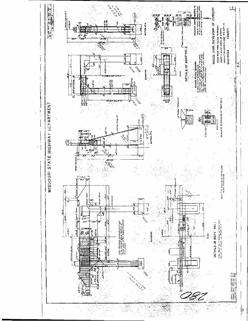
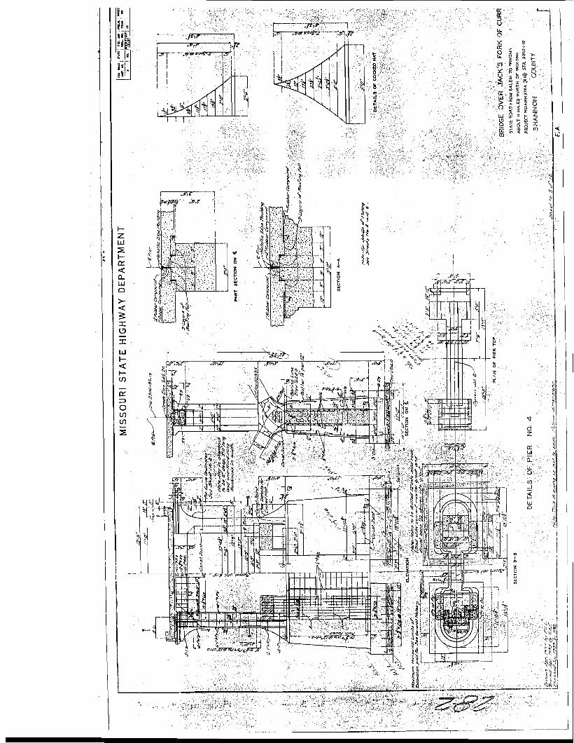
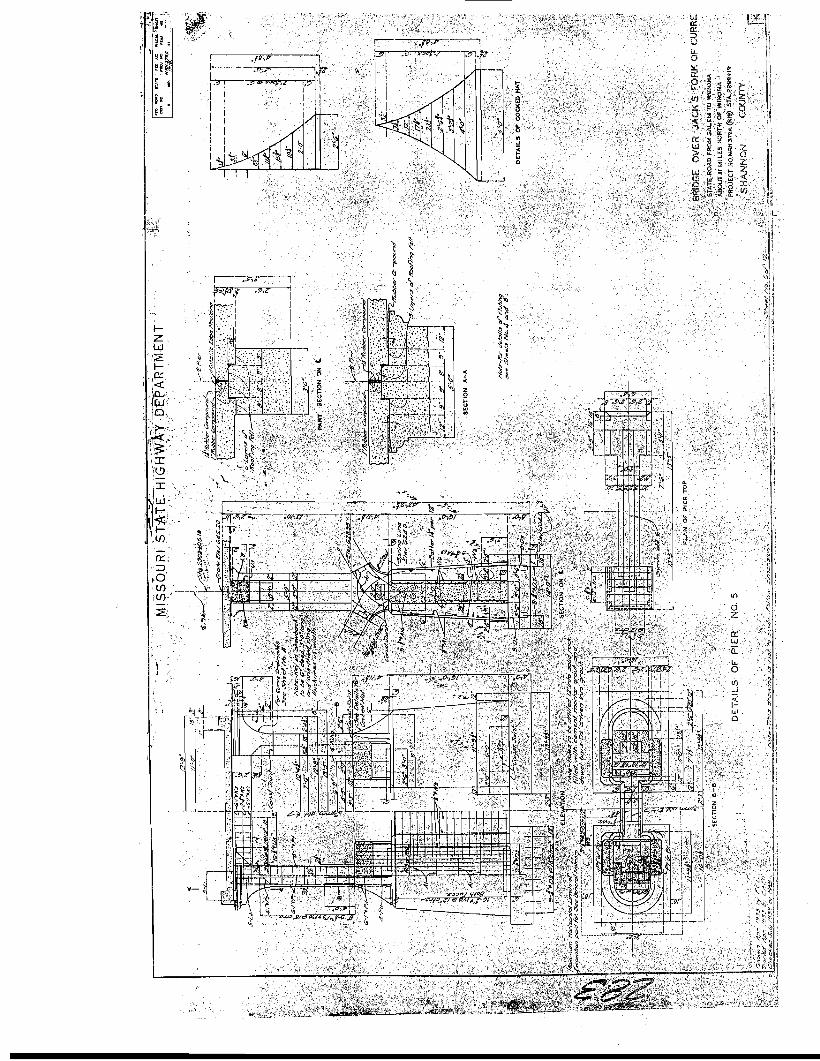
The substructure consists of two open abutments, one intermediate bent on the north side, and four piers. The substructure components are founded on solid bedrock. The footings of the four main piers are tied into the bedrock with ¾”-diameter steel dowels spaced at 1’-6” intervals, driven a foot into the rock and secured with cement mortar grout. Notations on the construction drawings indicate the planned dimensions of the piers and bents were slightly altered during construction when the excavations for the footings sometimes had to go slightly deeper than expected.
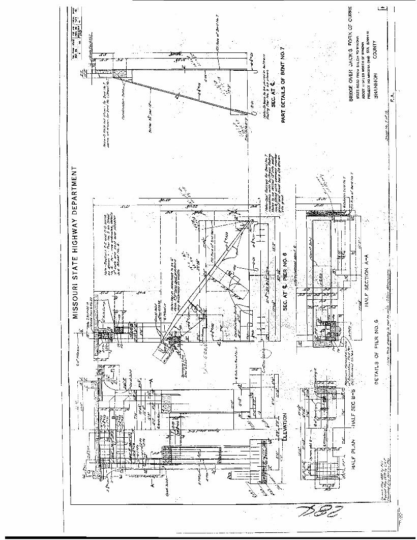
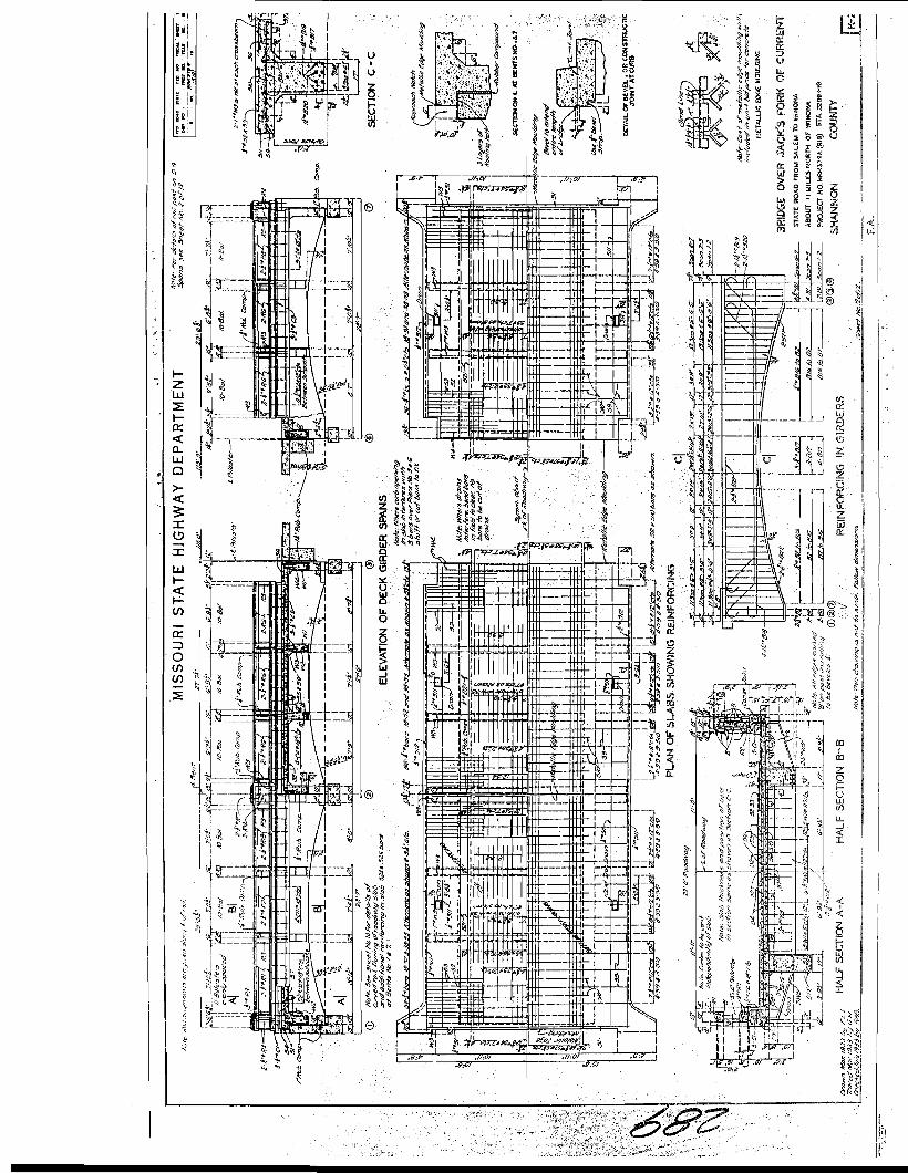
Bent 1 on the north bank has rectangular footings supporting two front-battered columns 2’-6” wide and approximately 29’ high. The columns are connected by a cap beam, with a backwall and wings 44’-4” long. Intermediate Bent 2 supporting two deck girder spans at the north end of the bridge rests on 4’-6”-square footings that support 2’-6”-square columns approximately 24’ high, with a connecting cap beam. Bent 7 on the south bank is larger than but similar to Bent 1. Bent 7 has two rectangular footings and two front-battered columns approximately 31’ high. The footings for Bent 7 were poured monolithic with the buttress footings of adjacent Pier 6. The arch buttresses extend from Pier 6 into the Bent 7 columns. Other dimensions of Bent 7 are the same as Bent 1.
17 Fraser, Missouri Historic Bridge Inventory, Vol. 1, pp. 83-143, passim. 18 Missouri State Highway Department, “Bridge Over Jack’s Fork of Current River,” Bridge No. K-209 design plans [eleven sheets].
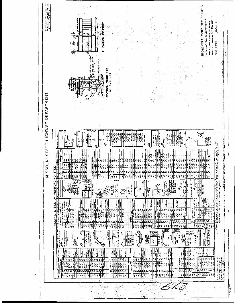
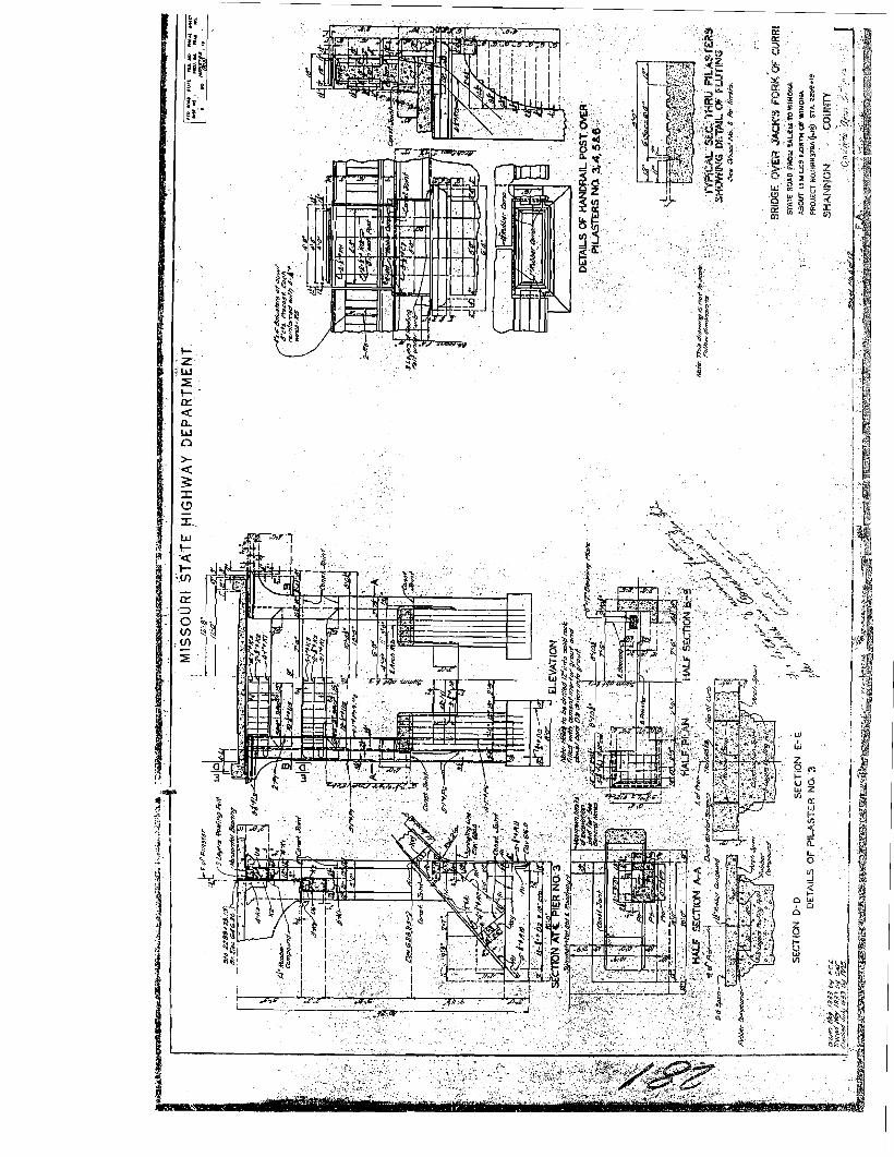
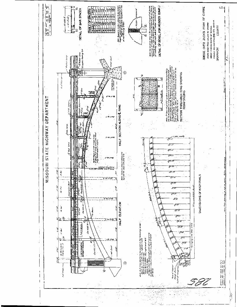
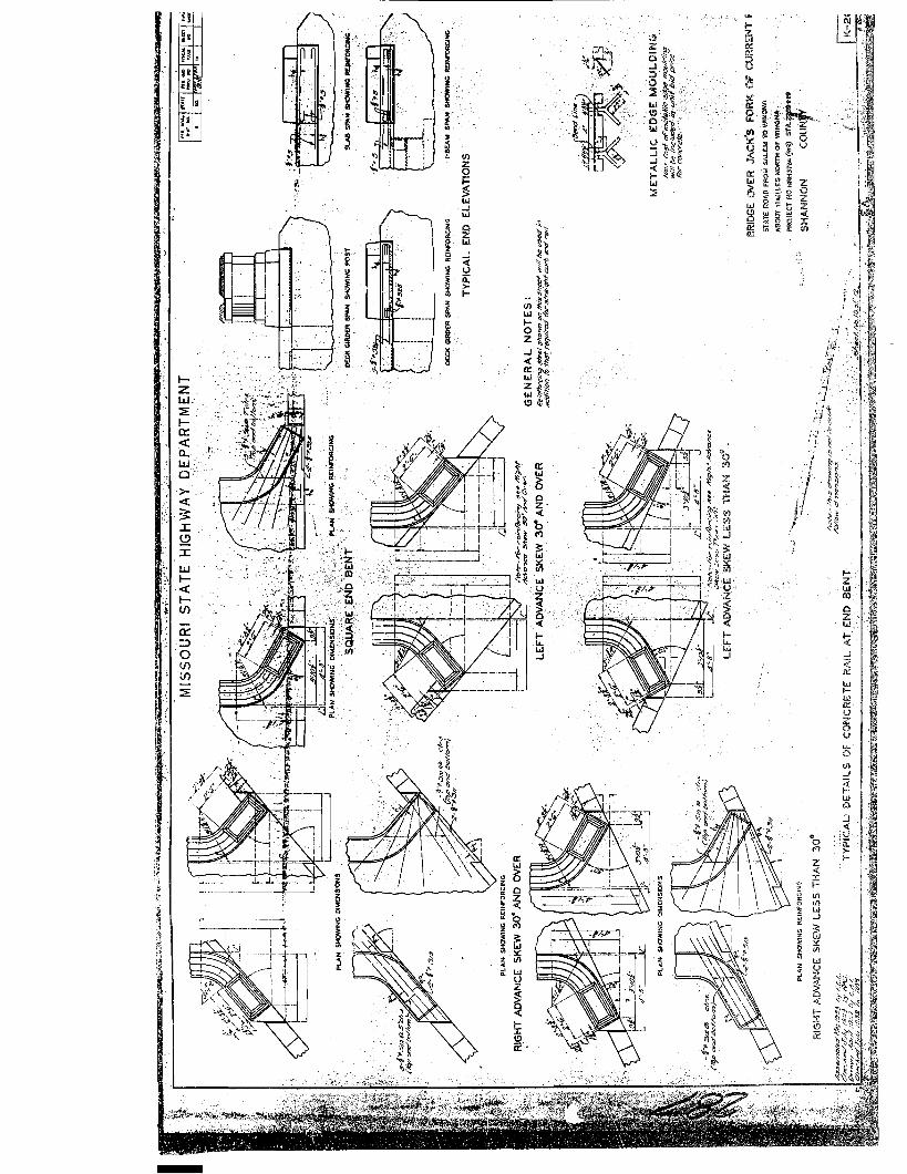
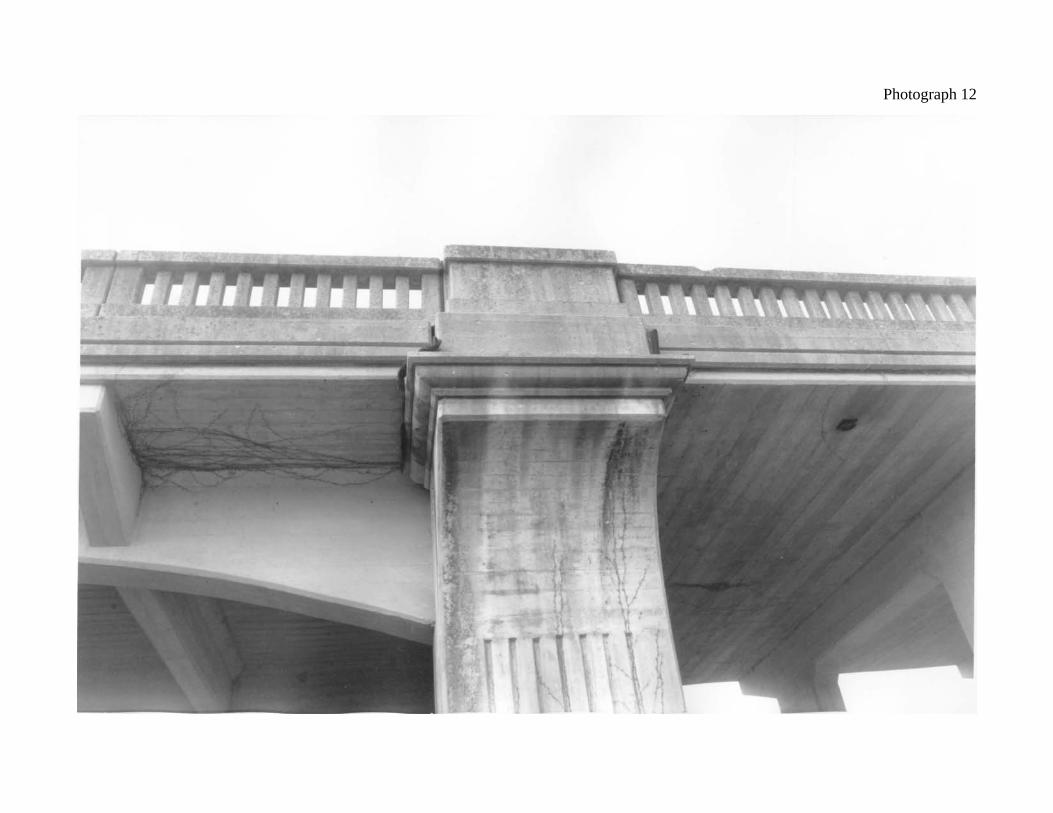
Piers 3 and 6 anchor the ends of the arch spans with large buttresses extending into the adjoining arch ribs. Pier 3 is an open pier founded on rectangular footings 20’-0” x 8’-0” x 3’-0”. Arch buttresses 5’-0” wide extend from the rear of the footings, where they are anchored with ½”-diameter reinforcing rods, to the front of the pier columns where there is a construction joint with the arch ribs. The pier columns are 5’-0” x 5’-0” square and 10’ high from the footings up to the juncture of the arch buttresses where there is a construction joint with the pilasters. The pier columns are connected with a 3’-0” x 1’-6” tie beam. Above the construction joint, the fluted pilasters are offset from the centers of the arch ribs. The pilasters become narrower at 5’-0” x 3’-0”, and are over 16’ high. Flared, beveled crowns extend out another 3’-0” to support the bridge deck balustrades. The pilasters are connected by a 2’-3” x 1’-9” tie beam, and a 1’-6” x 2’-9” cap beam. Pier 6 features a large footing poured monolithic with the footing for Bent 7. Combined, the footing measures 32’-2” x 11’-6” x 3’-0”. As the anchor for the arch ribs, the buttresses at Pier 6 extend the length of the footings through the Bent 7 columns to its rear face. The buttresses are strengthened and secured with 7/8” diameter reinforcing rods. The two pier columns are approximately 21’ high from the tops of the footings to the base of the tie beam, which corresponds to the arch spring line. Piers 4 and 5, the main channel piers, are nearly identical in dimensions. They consist of battered cylindrical columns approximately 12’ in diameter and 17’ high, connected by a 3’-0”-thick webwall. At the arch spring line, cone-shaped cutwaters labeled “cocked hats” deflect the current and reduce cross-currents on the downstream side. The fluted pilasters, offset from the arch ribs, are 5’-0” x 3’-0”, and are 21’-4” high from the spring line to the top of the cap beam. The spring line of the arch ribs is at an elevation of 624.0’. The arch ribs are 5’-0” wide with beveled edges, and are reinforced every 2’-6” with ½”-diameter steel reinforcement rods and angle bar spacers. They have a vertical thickness at the spring line of 2’-11”and narrow gradually to a thickness of 1’-6” at the crown. The rise of the arch measures 17’-3” from the spring line to the crown extrados. The arches are 115’-0” long as measured between the pier centerlines, or 110’-0” from the outside of the piers. The arches support spandrel bents which act as floor beams to support the bridge deck. The spandrel bents are placed symmetrically 11’-0-1/4” apart, giving eight bents per span. Cross struts between the arch ribs occur at Spandrel Bents 2 and 7. The spandrel bent columns are 1’-4” thick and 3’-6” wide, with cap beams 24’-0” long. Two reinforced concrete deck girder spans at the north end are 28’-7” long at Span 1 and 27’-6” long at Span 2. The south end deck girder span, Span 6, is also 28’-7” long. The arched girders are 1’-5” thick, with two floor beams at each span. The girder spans rest on alternating fixed and expansion phosphor bronze bearing plates. The bridge deck is 10-1/2” thick at the crown of the roadway. The guardrails on top of 10” curbs consist of 4” x 4” balustrades with beveled coping, subposts at the spandrel bents, and 2’-6”-wide beveled concrete posts at each pilaster, with curved entrance posts displaying the bridge plates. Expansion joints at the posts and subposts above the spandrel bents are filled with a rubber compound.

The Eminence Bridge remains largely unaltered from its original construction. It is a representative example of multiple-span open spandrel arch construction employed by the Missouri State Highway Department during the 1920s and 1930s. Generally, multiple-span bridges of this type have span lengths of around 100’. The general structural design and subdued decorative details of the Eminence Bridge also appear typical, in the symmetry of its arch spans, the fluted pilasters, the concrete balustrades and the curved entrances. Construction of a new bridge adjacent to the Eminence Bridge is scheduled to begin in January 2003. The Eminence Bridge will be preserved in place and used as a pedestrian crossing.
Eminence Bridge (Jacks Fork Bridge) Bridge No. K-209
Route 19, Shannon County
Randall Dawdy, Photographer
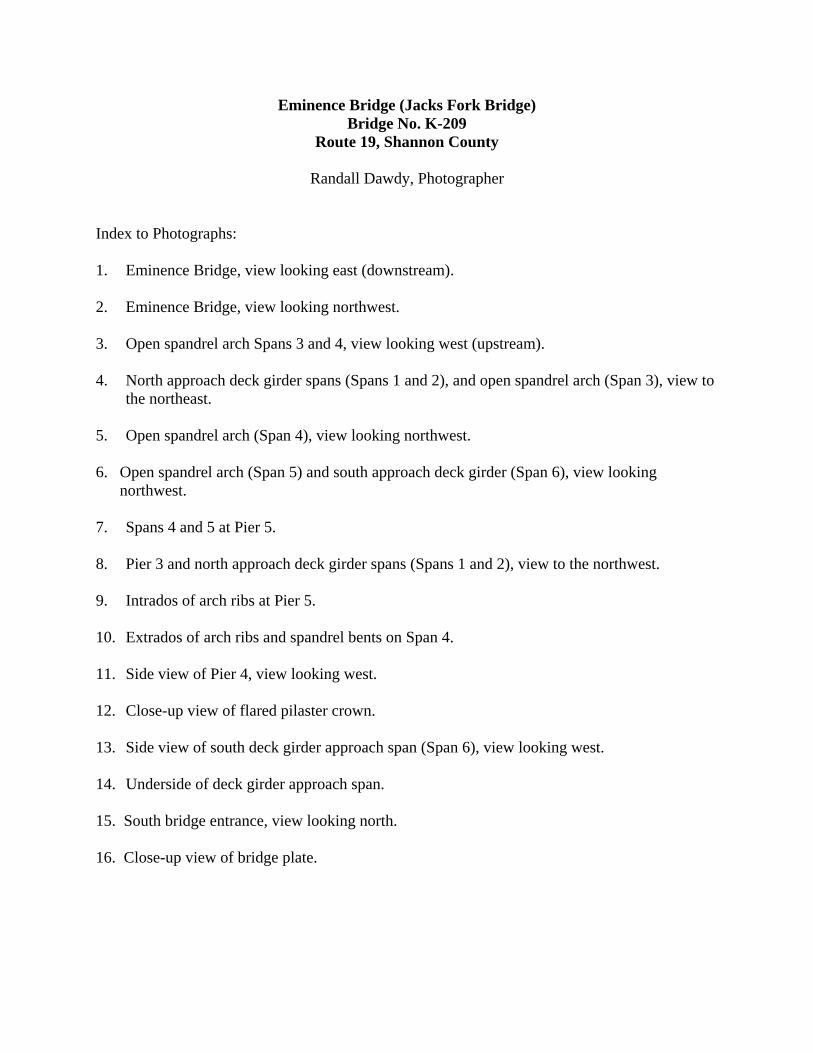
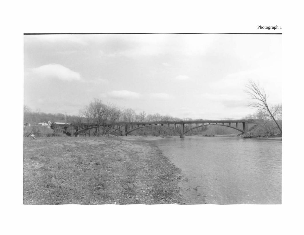
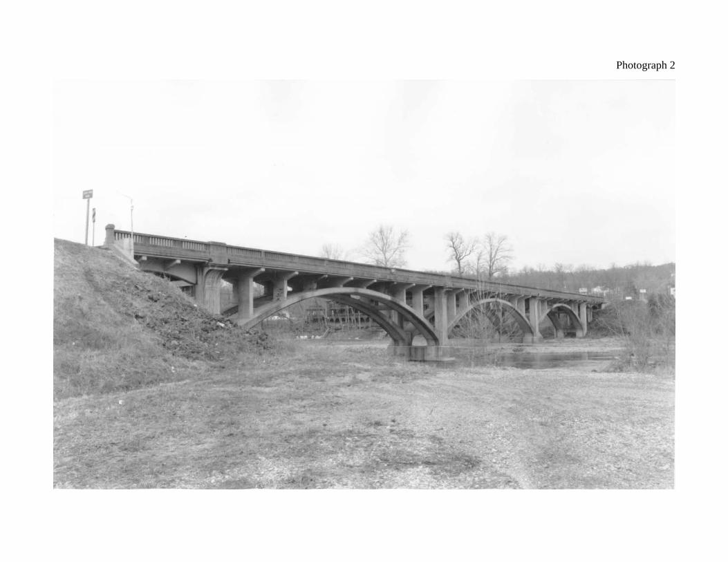
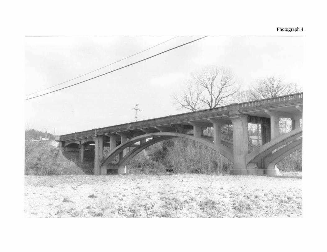
Index to Photographs: 1. Eminence Bridge, view looking east (downstream). 2. Eminence Bridge, view looking northwest. 3. Open spandrel arch Spans 3 and 4, view looking west (upstream). 4. North approach deck girder spans (Spans 1 and 2), and open spandrel arch (Span 3), view to
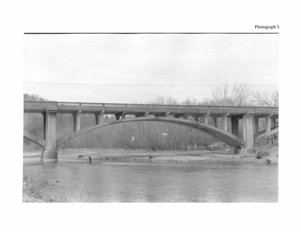
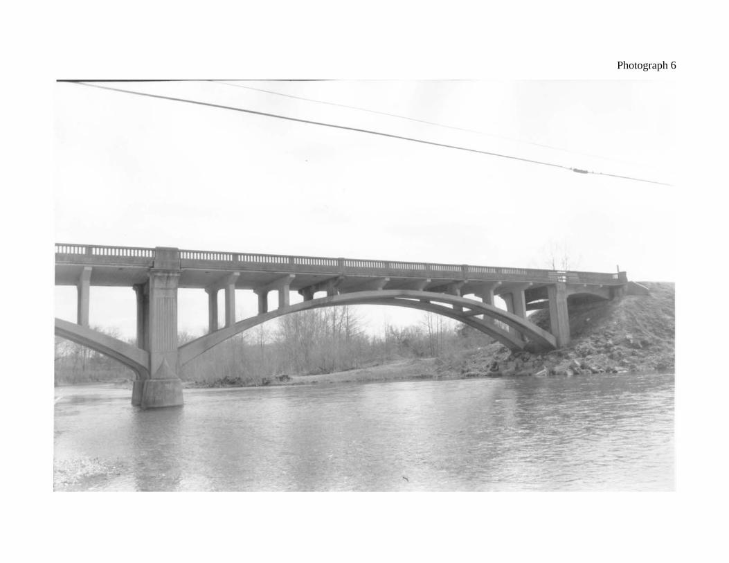
the northeast. 5. Open spandrel arch (Span 4), view looking northwest. 6. Open spandrel arch (Span 5) and south approach deck girder (Span 6), view looking
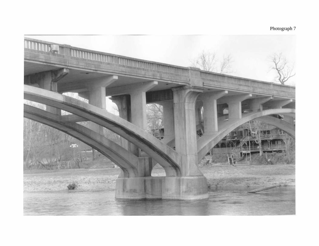
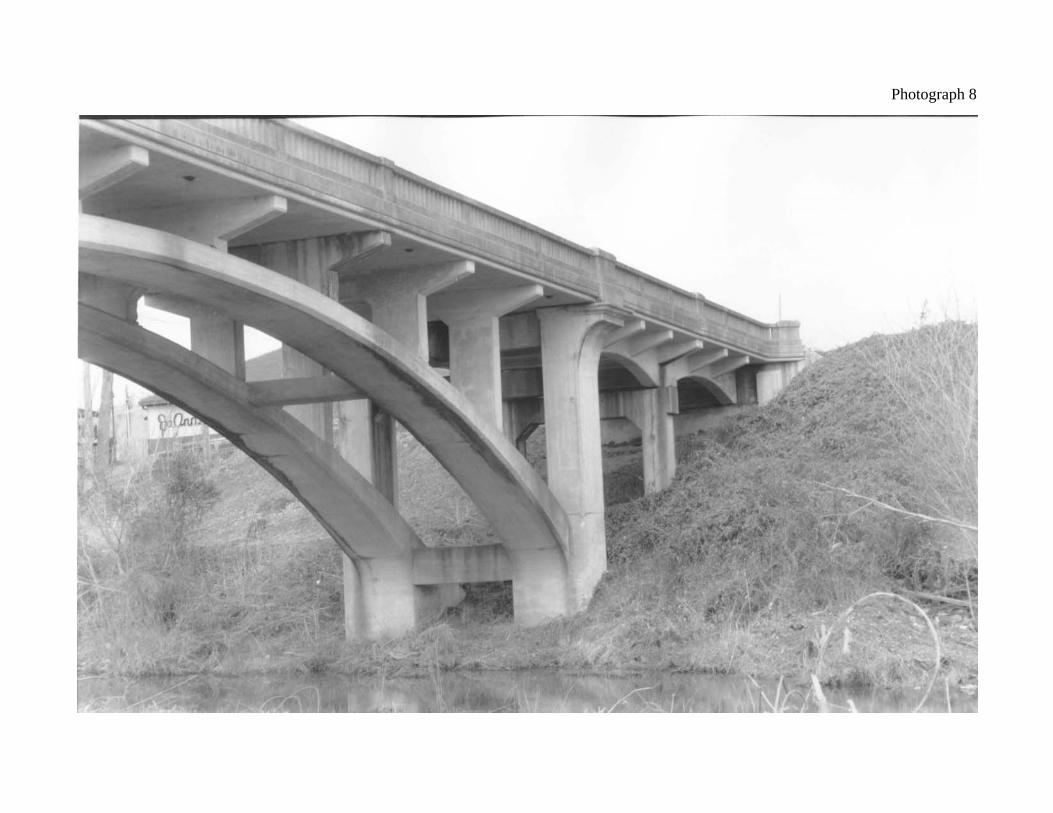
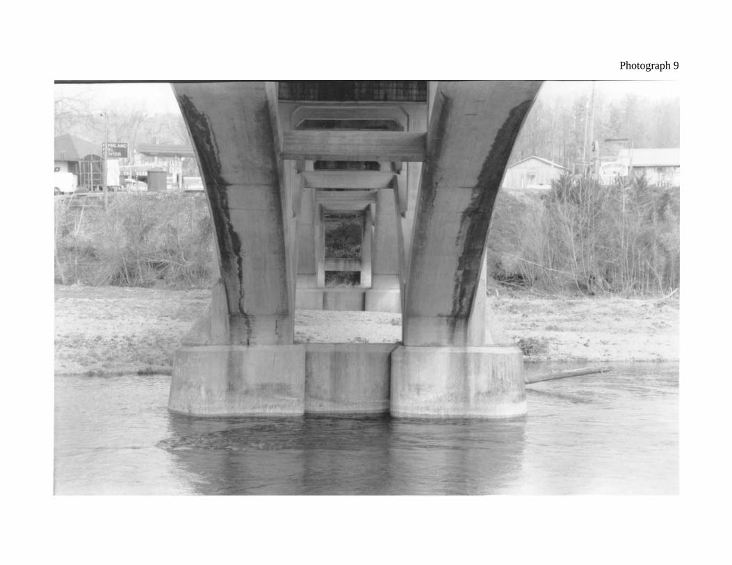
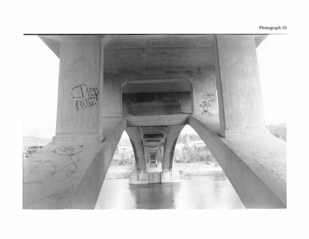
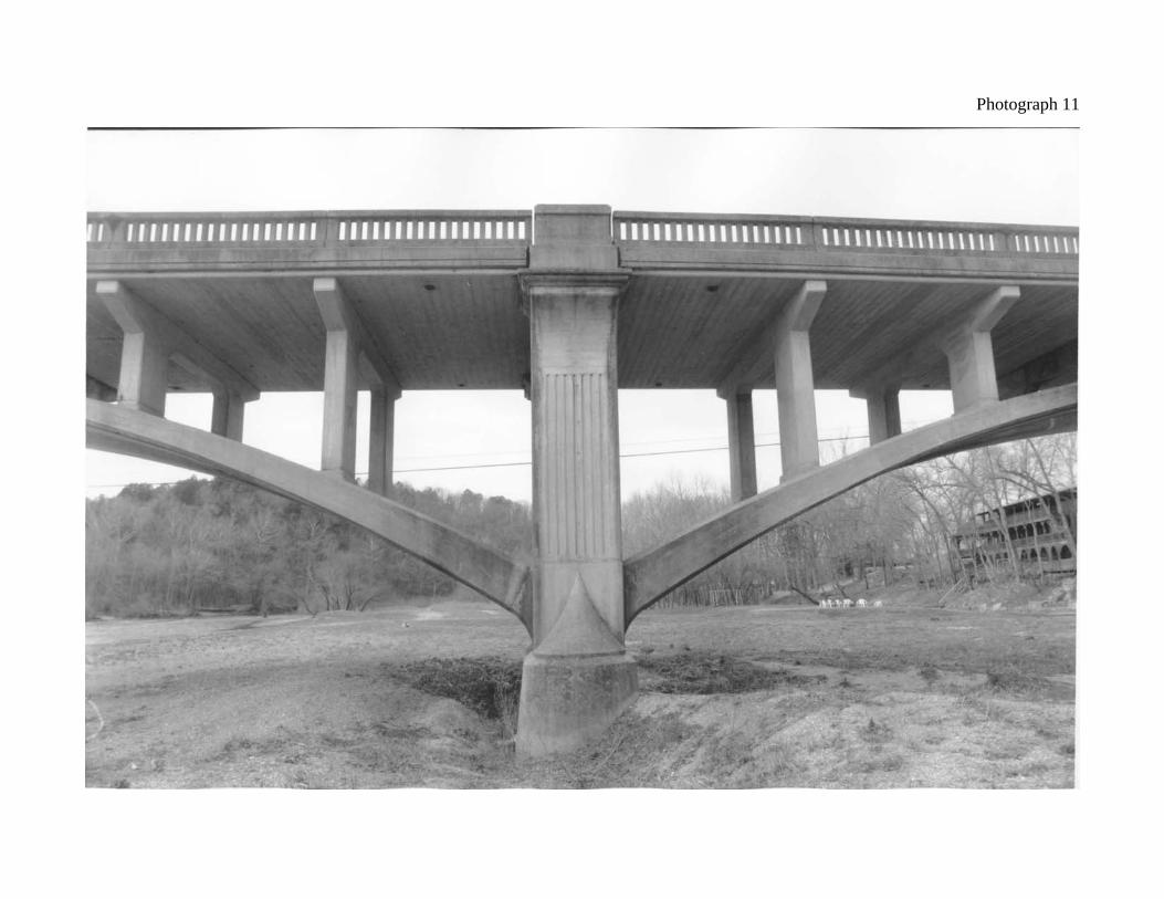
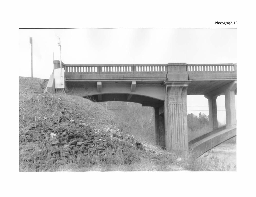
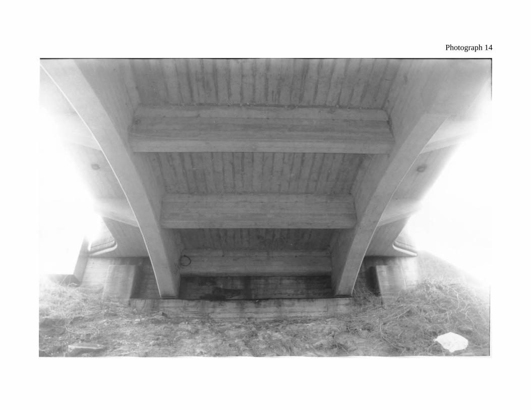
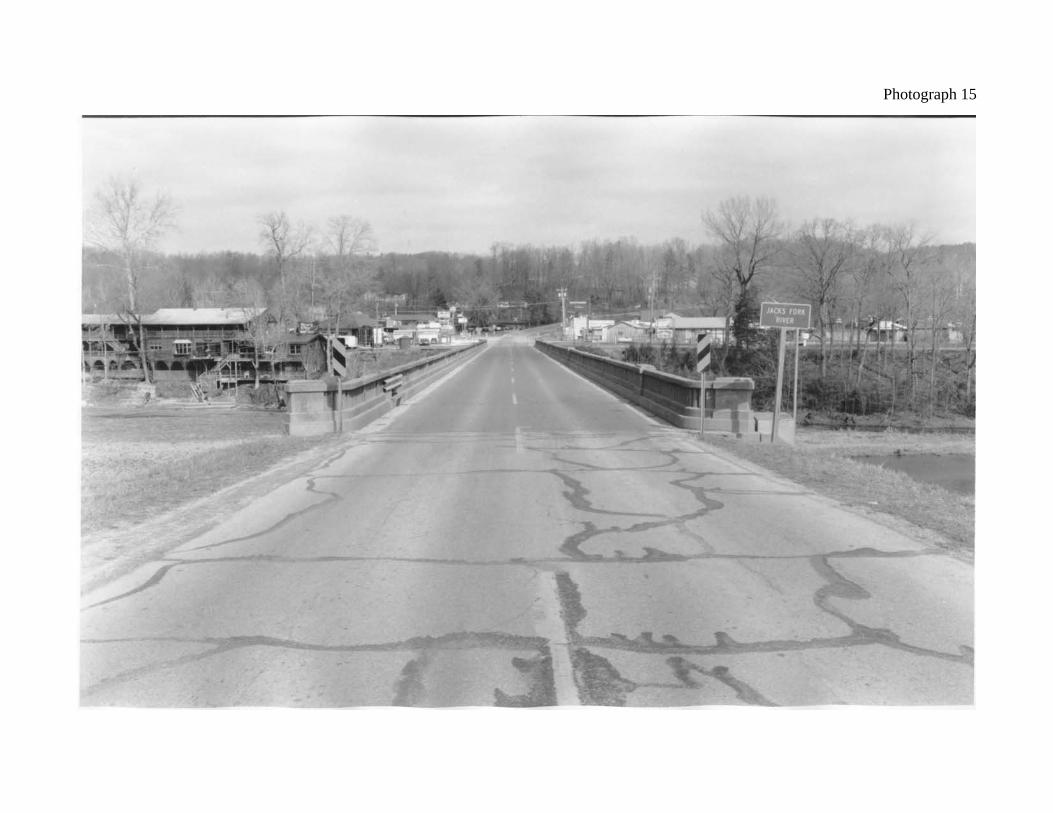
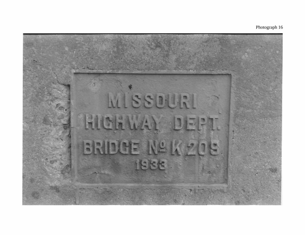
northwest. 7. Spans 4 and 5 at Pier 5. 8. Pier 3 and north approach deck girder spans (Spans 1 and 2), view to the northwest. 9. Intrados of arch ribs at Pier 5. 10. Extrados of arch ribs and spandrel bents on Span 4. 11. Side view of Pier 4, view looking west. 12. Close-up view of flared pilaster crown. 13. Side view of south deck girder approach span (Span 6), view looking west. 14. Underside of deck girder approach span. 15. South bridge entrance, view looking north. 16. Close-up view of bridge plate.
Photograph 1
Photograph 2
Photograph 3
Photograph 4
Photograph 5
Photograph 6
Photograph 7
Photograph 8
Photograph 9
Photograph 10
Photograph 11
Photograph 12
Photograph 13
Photograph 14
Photograph 15
Photograph 16