Embed Size (px)
Citation preview
Documentation DDC4000
Documentation DDC4000Documentation to set up and maintain the DDC4000.
Version releasedfor DDC4000
Released by Comment
0.10 v. 14.10.2004 ß test - To use as part of the ß test.
0.11 v. 21.10.2004 - - Updating
0.12 v. 13.12.2004 ß - Manual influence in DDC, network settings for PPP,
0.13 v. 05.01.2005 ß - Directory structure reworked, expression corrections -initiated by Wlk/FE
0.14 v. 10.03.2006 Version 1.0.xx PAW System objects reworked (FAX, EMAIL, Config)
0.15 v. 21.3.2006 Version 1.0.xx PAW Software objects reworked (additions on the basis of thespecifications)
0.16 v. 04.04.2006 Version 1.1.xx PAW general revision, system objects added
1.0 v. 23.05.2006 Version 1.1.xx PAW first variant for export
1. Introduction
2. Operation
3. Plant components and bus systems
4. Software structure
Version 05/06

Introduction 1. - 2
1. Introduction
1. Introduction .................................................................................................................................... 2
1.1. The idea behind the DDC 4000 ................................................................................................... 3
1.2. Structure of the DDC 4000 system ............................................................................................. 5
Version 05/06
Introduction The idea behind the DDC 4000 1.1. - 3
1.1. The idea behind the DDC 4000
The DDC4000 Central Units and bus modules are extensions to the Kieback&Peter product rangeproviding a plant with new options. The following objectives were aimed at and achieved with the development of the DDC4000 system:
Ethernet communication between the DDC4000 Central Units and BMSThe central station communication of the DDC4000 system is implemented over the Ethernet.Through the use of current network technology it is possible to connect to the service laptop, BMSor customer networks as well as to network various DDC4000 Central Units cost-effective.If an existing JY(St)Y cabling is to be used there is still the option of communicating via thistraditional "telephone cable". But for this it is not possible to use the Ethernet's data rate.
Flexible, user-friendly user interfaceThe use of a touch screen TFT color display provides a flexible, future-oriented interface that iseasy and intuitive to operate and does not have restrictions for future extensions.
BACnet nativeThe DDC4000 communicates via the standardized protocol BACnet. BACnet operates in the DDCCentral Unit down up to the database structure. This is called a native BACnet implementation.Each parameter is administrated as a BACnet object and for example transported to the BMS. Thismeans unproblematic connection to BACnet clients and therefore minimal projecting effort.
Structured parameterizingBy illustrating individual plants and their classification in groups, a clearly structured, re-usableprojecting is possible. On that ground existing plant elements can be combined with new ones withthe lowest effort.
Remote control via any Windows PC without additional softwareTo operate and project a DDC4000 central unit you only need a network connection and Internetexplorer. No plug-in or additional programs are required. The usual port 80 is used forcommunication.As a result of the Internet integration, access is possible from almost anywhere in the world.
checked controls for plant elementsThe hardware objects, commented later, provide all the usual functions to control the commonplant parts, such as pumps, valves, burners etc. The processing of many functions such asoperating hour counting and command execution check has already been integrated and is readyfor use.
2 CAN buses for each DDC4000 central station (each can be switched as a control cabinetor field bus)Both CAN buses can be used as either a field bus or control cabinet bus. This permits higherflexibility for utilizing resources. Many of the known bus devices from the DDC3000 system can stillbe used; new modules will receive additional functions.
Switch modules on the touch screenWith the depiction of switches, lamps and values you can easily and effectively implement theindividually produced manual operating level.
separate customer and service interfaceThe service interface is separate from the intuitive operating interface. It provides a structured andfast access to all functions. The complete plant functionality can be produced or changed from thisinterface.
Integration in the planning toolFor fast and effective DDC4000 projecting the planning system PS4000 provides all kinds ofsupport. A flexible database structure ensures that the new DDC4000 functions can be usedimmediately in the planning system.
Version 05/06

Introduction The idea behind the DDC 4000 1.1. - 4
high computing powerThrough the use of modern processors, new memory components and the use of the future-oriented and apparently virus-free Linux operating system very powerful DDC Central Units arecreated.
Version 05/06
Introduction Structure of the DDC 4000 system 1.2. - 5
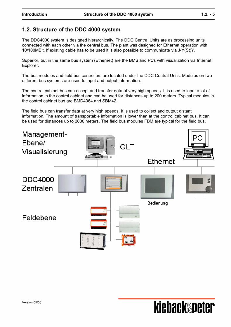
1.2. Structure of the DDC 4000 system
The DDC4000 system is designed hierarchically. The DDC Central Units are as processing unitsconnected with each other via the central bus. The plant was designed for Ethernet operation with10/100MBit. If existing cable has to be used it is also possible to communicate via J-Y(St)Y. Superior, but in the same bus system (Ethernet) are the BMS and PCs with visualization via InternetExplorer. The bus modules and field bus controllers are located under the DDC Central Units. Modules on twodifferent bus systems are used to input and output information. The control cabinet bus can accept and transfer data at very high speeds. It is used to input a lot ofinformation in the control cabinet and can be used for distances up to 200 meters. Typical modules inthe control cabinet bus are BMD4064 and SBM42. The field bus can transfer data at very high speeds. It is used to collect and output distantinformation. The amount of transportable information is lower than at the control cabinet bus. It canbe used for distances up to 2000 meters. The field bus modules FBM are typical for the field bus.
Version 05/06
Introduction Structure of the DDC 4000 system 1.2. - 6
DDC400 central units model variants
DDC4200: Color 5.7" TFT touch screen DDC4100: Black and white screen with single button operation DDC4400: Black box: DDC4000 Central Unit without operating elements
Displaced displays
DDC4001: touch screen to operate the complete DDC network
Structure of planning and user guidance
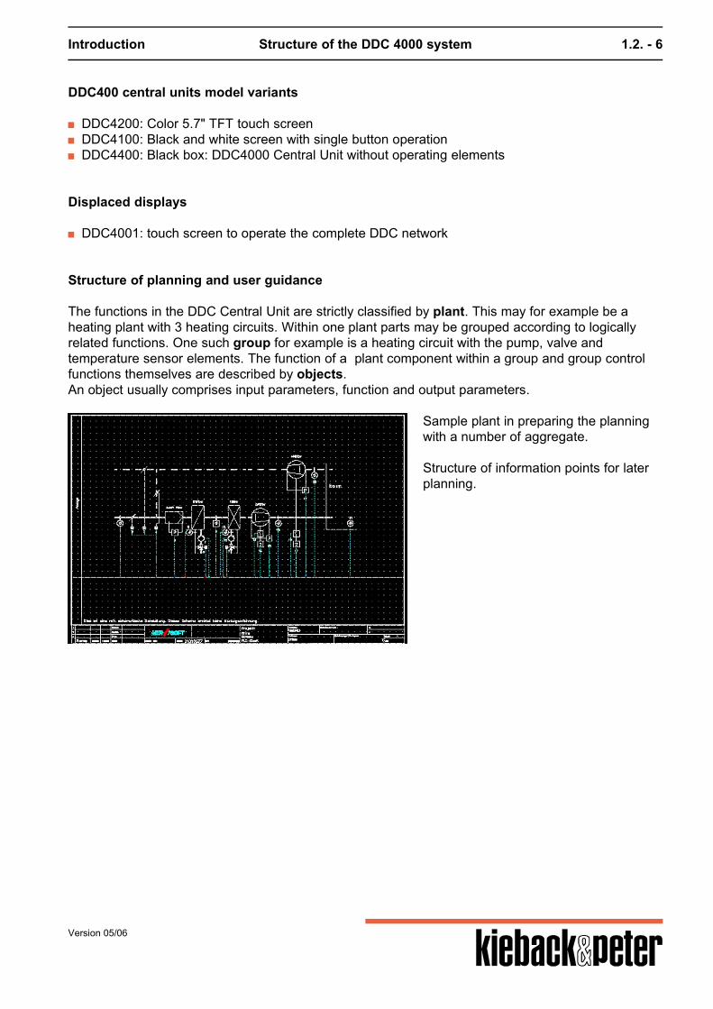
The functions in the DDC Central Unit are strictly classified by plant. This may for example be aheating plant with 3 heating circuits. Within one plant parts may be grouped according to logicallyrelated functions. One such group for example is a heating circuit with the pump, valve andtemperature sensor elements. The function of a plant component within a group and group controlfunctions themselves are described by objects.An object usually comprises input parameters, function and output parameters.
Sample plant in preparing the planningwith a number of aggregate. Structure of information points for laterplanning.
Version 05/06
Introduction Structure of the DDC 4000 system 1.2. - 7
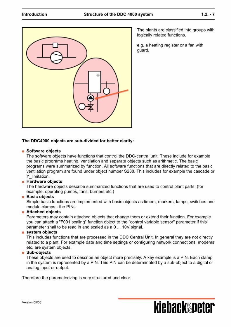
The plants are classified into groups withlogically related functions. e.g. a heating register or a fan withguard.
The DDC4000 objects are sub-divided for better clarity:
Software objectsThe software objects have functions that control the DDC-central unit. These include for examplethe basic programs heating, ventilation and separate objects such as arithmetic. The basicprograms were summarized by function. All software functions that are directly related to the basicventilation program are found under object number S238. This includes for example the cascade orY_limitation.
Hardware objectsThe hardware objects describe summarized functions that are used to control plant parts. (forexample: operating pumps, fans, burners etc.)
Basic objectsSimple basic functions are implemented with basic objects as timers, markers, lamps, switches andmodule clamps - the PINs.
Attached objectsParameters may contain attached objects that change them or extend their function. For exampleyou can attach a "F001 scaling" function object to the "control variable sensor" parameter if thisparameter shall to be read in and scaled as a 0 ... 10V signal.
system objectsThis includes functions that are processed in the DDC Central Unit. In general they are not directlyrelated to a plant. For example date and time settings or configuring network connections, modemsetc. are system objects.
Sub-objectsThese objects are used to describe an object more precisely. A key example is a PIN. Each clampin the system is represented by a PIN. This PIN can be determinated by a sub-object to a digital oranalog input or output.
Therefore the parameterizing is very structured and clear.
Version 05/06

Operation 2. - 8
2. Operation
2. Operation ........................................................................................................................................ 8
2.1. Introduction to operation ............................................................................................................ 9
Version 05/06
Operation Introduction to operation 2.1. - 9
2.1. Introduction to operation
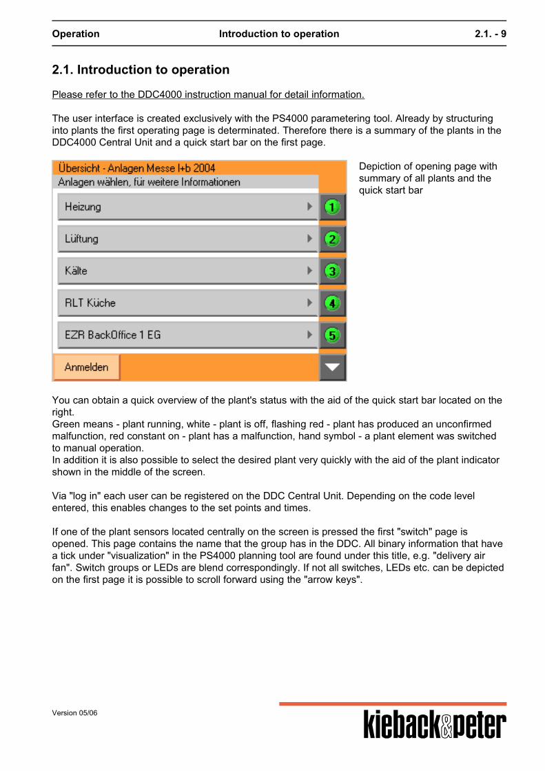
Please refer to the DDC4000 instruction manual for detail information. The user interface is created exclusively with the PS4000 parametering tool. Already by structuringinto plants the first operating page is determinated. Therefore there is a summary of the plants in theDDC4000 Central Unit and a quick start bar on the first page.
Depiction of opening page withsummary of all plants and thequick start bar
You can obtain a quick overview of the plant's status with the aid of the quick start bar located on theright.Green means - plant running, white - plant is off, flashing red - plant has produced an unconfirmedmalfunction, red constant on - plant has a malfunction, hand symbol - a plant element was switchedto manual operation.In addition it is also possible to select the desired plant very quickly with the aid of the plant indicatorshown in the middle of the screen. Via "log in" each user can be registered on the DDC Central Unit. Depending on the code levelentered, this enables changes to the set points and times. If one of the plant sensors located centrally on the screen is pressed the first "switch" page isopened. This page contains the name that the group has in the DDC. All binary information that havea tick under "visualization" in the PS4000 planning tool are found under this title, e.g. "delivery airfan". Switch groups or LEDs are blend correspondingly. If not all switches, LEDs etc. can be depictedon the first page it is possible to scroll forward using the "arrow keys".
Version 05/06
Operation Introduction to operation 2.1. - 10
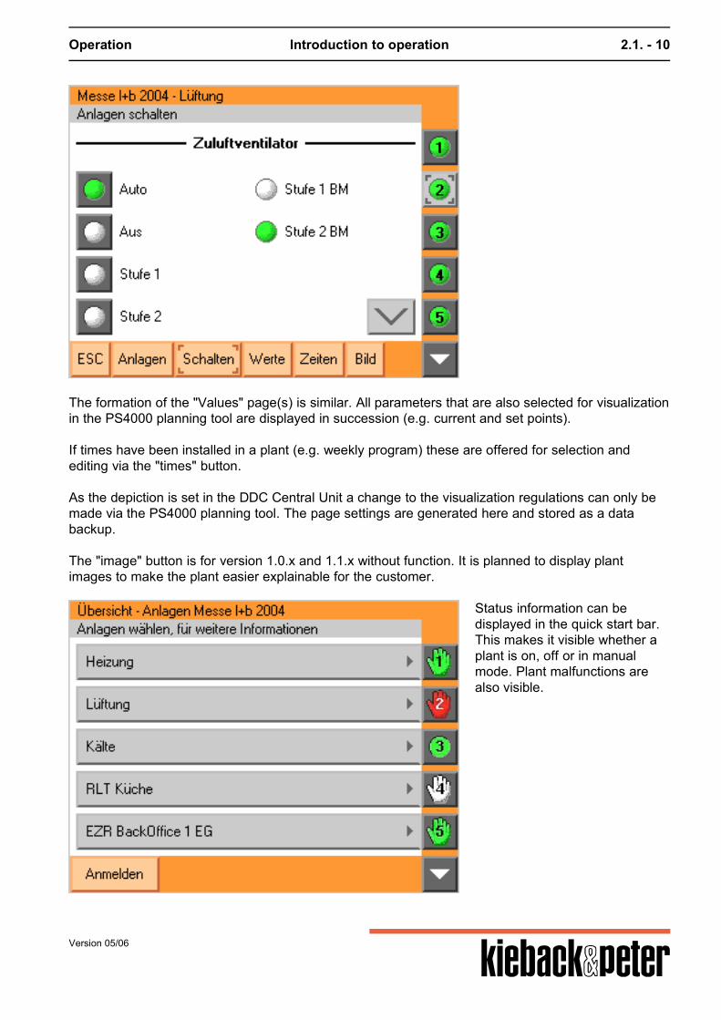
The formation of the "Values" page(s) is similar. All parameters that are also selected for visualizationin the PS4000 planning tool are displayed in succession (e.g. current and set points). If times have been installed in a plant (e.g. weekly program) these are offered for selection andediting via the "times" button. As the depiction is set in the DDC Central Unit a change to the visualization regulations can only bemade via the PS4000 planning tool. The page settings are generated here and stored as a databackup.
The "image" button is for version 1.0.x and 1.1.x without function. It is planned to display plantimages to make the plant easier explainable for the customer.
Status information can bedisplayed in the quick start bar.This makes it visible whether aplant is on, off or in manualmode. Plant malfunctions arealso visible.
Version 05/06
Plant components and bus systems 3. - 11
3. Plant components and bus systems
3. Plant components and bus systems ......................................................................................... 11
3.2. central unit bus (Ethernet) ........................................................................................................ 123.2.1. DDC Central Units .................................................................................................................... 123.2.1.1. DDC4200 ............................................................................................................................... 123.2.1.1.1. Connection occupancy ....................................................................................................... 123.2.1.1.2. Technical data .................................................................................................................... 123.2.1.1.3. LV help (bids) ...................................................................................................................... 143.2.2. Touch panel .............................................................................................................................. 163.2.2.1. DDC4001 ............................................................................................................................... 163.2.2.1.1. Connection occupancy ....................................................................................................... 163.2.2.1.2. Technical data .................................................................................................................... 163.2.3. Central communication Ethernet .............................................................................................. 163.2.3.1. General .................................................................................................................................. 163.2.3.2. Ethernet ................................................................................................................................. 173.2.3.2.1. Network settings Sy_Network ............................................................................................. 173.2.3.2.2. Other DDC Central Units in the network ............................................................................. 193.2.3.2.3. Ethernet tests ...................................................................................................................... 193.2.3.3. PC operation with a browser .................................................................................................. 203.2.3.5. BMS connection ..................................................................................................................... 253.2.3.6. BACnet ................................................................................................................................... 25
3.4. control cabinet bus .................................................................................................................... 293.4.1. General ..................................................................................................................................... 293.4.1.1. Installation .............................................................................................................................. 293.4.1.3. Power supply ......................................................................................................................... 293.4.2. BMA4024 .................................................................................................................................. 293.4.3. BMD4032 .................................................................................................................................. 323.4.4. BMD4064 .................................................................................................................................. 333.4.5. SBM51_04 ................................................................................................................................ 35
3.5. Field bus ..................................................................................................................................... 413.5.1. General ..................................................................................................................................... 413.5.2. Modules .................................................................................................................................... 41
Version 05/06
Plant components and bus systems central unit bus (Ethernet) 3.2. - 12
3.2. central unit bus (Ethernet)
3.2.1. DDC Central Units
3.2.1.1. DDC4200
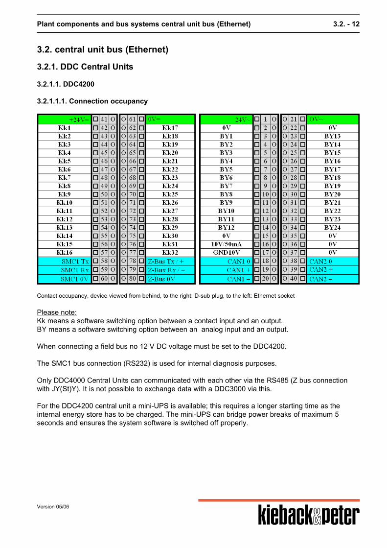
3.2.1.1.1. Connection occupancy
Please note:Kk means a software switching option between a contact input and an output.BY means a software switching option between an analog input and an output. When connecting a field bus no 12 V DC voltage must be set to the DDC4200. The SMC1 bus connection (RS232) is used for internal diagnosis purposes. Only DDC4000 Central Units can communicated with each other via the RS485 (Z bus connectionwith JY(St)Y). It is not possible to exchange data with a DDC3000 via this. For the DDC4200 central unit a mini-UPS is available; this requires a longer starting time as theinternal energy store has to be charged. The mini-UPS can bridge power breaks of maximum 5seconds and ensures the system software is switched off properly.
Version 05/06
Contact occupancy, device viewed from behind, to the right: D-sub plug, to the left: Ethernet socket
Plant components and bus systems central unit bus (Ethernet) 3.2. - 13
3.2.1.1.2. Technical data
DDC control circuits
Within the DDC4200 are 12 control circuits available. This matches the range of functions in theDDC3200.
Bus connection
Ethernet99 DDC4000 Central Units can be administrated,networked globally via active network components,10/100 Mbits/s
2 CAN busses, can be switched individually as a field or control cabinet bus– Field Bus; F Bus:
63 FieldBusModule FBM (in future there are plans for 99 FBMs);2000m; 20kBaud, CAN, J-Y(St) Y 2x2x0,8mm²At the point furthest from the central unit a termination resistance of 180 Ohm must be attachedbetween "BUS+" and "BUS-".
– Control Cabinet Bus; SBM Bus:16 ControlCabinetBusModules SBM;200m; 40kBaud, CAN
Interfaces
serial RS232Modem, printer
CompactFlashfor CompactFlash card; update, data backup / file recovery (behind the front panel)
Inputs and outputs
32 binary inputs (BE), can be switched individually as binary outputs (BA) by the softwareTransistor output: Contact load 24V DC; max. 50mAInput: to be attached through potential-free contact, of which 8 BE for counting pulses to 80Hz
24 analog inputs (AE), can be switched individually as analog outputs (AA) by the software
Sensor type Value range and unit
0..10V 0 to 100%
KP10 -50 to +150°C
Pt100 -50 to +150°C
Pt1000 -50 to +150°C
Ni100 -50 to +150°C
Version 05/06
Plant components and bus systems central unit bus (Ethernet) 3.2. - 14
Sensor type Value range and unit
Ni1000 (DIN) -50 to +150°C
Ni1000 (L&G) -50 to +150°C
KP250 -50 to +150°C
ML2 -50 to +150°C
Operating voltage
for DDC Central Unit24V AC +/-10%; 50..60Hz; 33 VA; 1,4A or24V DC +/-10%; 14,4 VA; 0,6A or12V DC +/-10%; 12 VA; 1,0A
For inputs and outputs24V DC +/-10%
More data:
Fuses Mains fuse, T 3.15A
Displays Back-lit color TFT LCD display
Switches/ buttons 1 button to reset the device
Processor MPC855T; 32 Bit; 80 MHz
Memory 128 MByte Flash Disc, 48MByteSDRAM;1 MByte Flash-PROM (boot)
Operating plant Embedded Linux
Power outage data backup 10 years, clock component battery-buffered
enclosure type IP30
Ambient temperature 0..45°C
Environmental humidity In service: 20..80%rF, non-condensing; inoperative: 5..90%rF, non-condensing
Housing 19" short plastic cassette, 4-way cassette with a base and special connections forEthernet and RS232 W x H x D; 202mm x 132mm x 137mm
Front panel cutout 200.4mm x 112.0mm
Weight 2,200kg
Designation CE
3.2.1.1.3. LV help (bids)
To complete service directories (SD)
Version 05/06
Plant components and bus systems central unit bus (Ethernet) 3.2. - 15
Automation stationProcessor type: MPC 855TWord length (bit): 32Max. cycle time (ms): 100AD/DA converter (bit): 16Max buffer time, real time clock: At least 5 yearsMax buffer time, data: Compact Flash unlimited Size and type(MB)read-only memory: 128 MB Compact Flashmain memory: 48 MB RAMMax. number of control circuits that can be processed: 21 Max. number of information points that can be processedPhysical: 2 x 16 x 24 binary inputscommunicative: approx. 5000 Max. number of connectablephysical input/output components: 2 x 63 Basic software functions can be extendedType of expansion: Software objects Local operating and display unitVariation 1:Does the Modular AS havean integrated operating and display unit as standard? YesVariation 2:Can the Modular AS be extended with an integratableoperating and display unit? YesType: DDC4001Variation 3:Can an external operating and display unitbe connected? YesType: PC with browser Which services can be carried out with the operating and display unit in the variants promted above?Variants 1, 2 and 3 can be operated, observed and parameterized. Is bus-wide access to other Modularautomation stations possible? yes Can an I/O component be deleted from the component bracketwithout affecting other AS components? yes (even under voltage) Is the deletion of an I/O component fromthe AS detected and is this information availablefor further processing? yes
Version 05/06
Plant components and bus systems central unit bus (Ethernet) 3.2. - 16
3.2.2. Touch panel
3.2.2.1. DDC4001
3.2.2.1.1. Connection occupancy
3.2.2.1.2. Technical data
The DDC4001 includes a PC with touch screen functions. All depictions are made in full-screen modewith Internet Explorer. External size of DDC4001Total dimensions W x H: (300 x 217.5) mmSection in control cabinet W x H: (280 x 197.5) mmDisplay cut-out (171 x 128) mmDisplay diagonals: 213.6 mm (8.4")
3.2.3. Central communication Ethernet
3.2.3.1. General
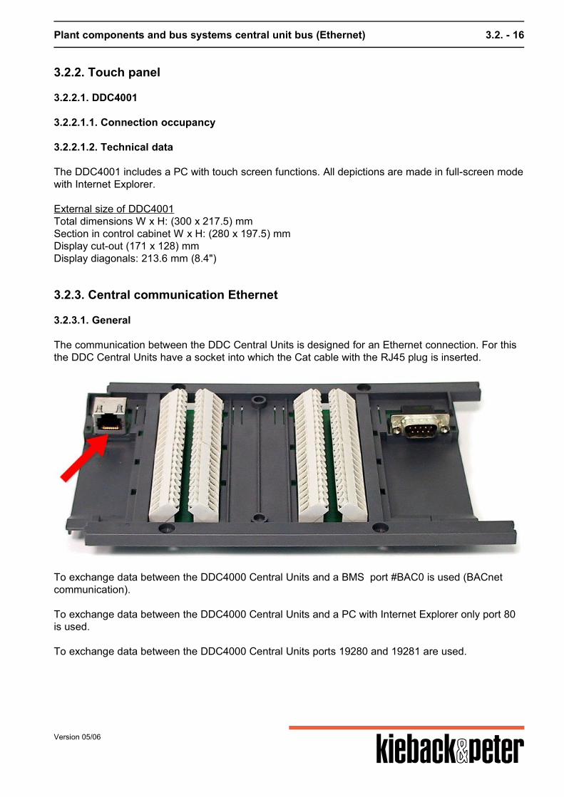
The communication between the DDC Central Units is designed for an Ethernet connection. For thisthe DDC Central Units have a socket into which the Cat cable with the RJ45 plug is inserted.
To exchange data between the DDC4000 Central Units and a BMS port #BAC0 is used (BACnetcommunication). To exchange data between the DDC4000 Central Units and a PC with Internet Explorer only port 80 is used. To exchange data between the DDC4000 Central Units ports 19280 and 19281 are used.
Version 05/06
Plant components and bus systems central unit bus (Ethernet) 3.2. - 17
3.2.3.2. Ethernet
To use the Ethernet interface the socket on the back of the device is connected with a network cabletype Cat.5 (or Cat.6, Cat.7). A difference is made between 1:1 connection (so-called patch cables)and cross-over cables. Cross-over cables are for directly connecting two devices, e.g. a DDC4000and a service PC. In all other cases a patch cable should be used for example in combination with aswitch. For communication each DDC4000 can use up to 3 IP addresses: 1. for all services when using Ethernet cabling2. if J-Y(St)Y cabling is used and3. for connecting via the modem (PPP) The IP addresses and sub-network mask and any essential gateway address are provided by yoursystem administrator. If a closed network is to be set up, that has no connection to the outside world,the IP addresses can be assigned freely. The recommendation in this case is to use the addresses 192.168.1.nnn for the Ethernet connection.This address is set by default.
3.2.3.2.1. Network settings Sy_Network
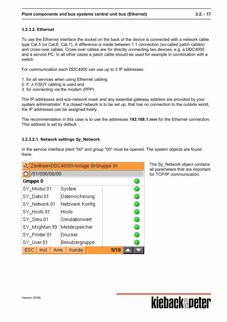
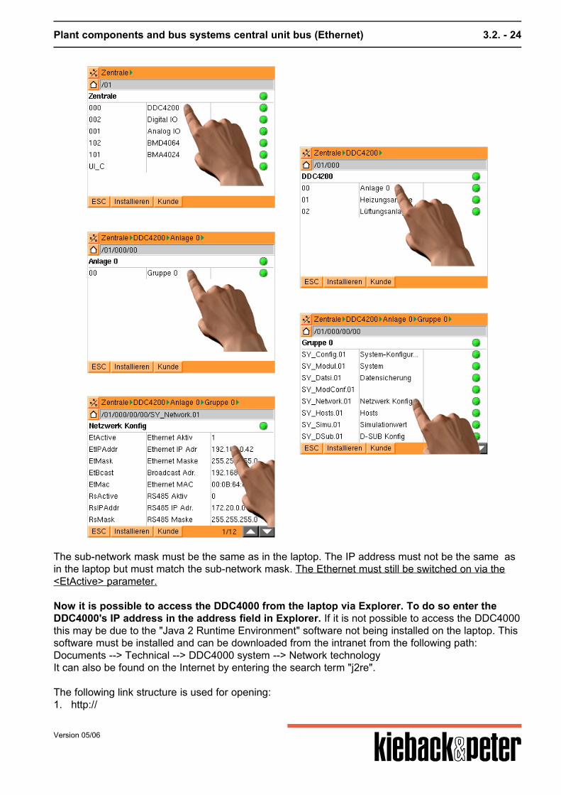
In the service interface plant "00" and group "00" must be opened. The system objects are foundthere.
The Sy_Network object containsall parameters that are importantfor TCP/IP communication.
Version 05/06
Plant components and bus systems central unit bus (Ethernet) 3.2. - 18
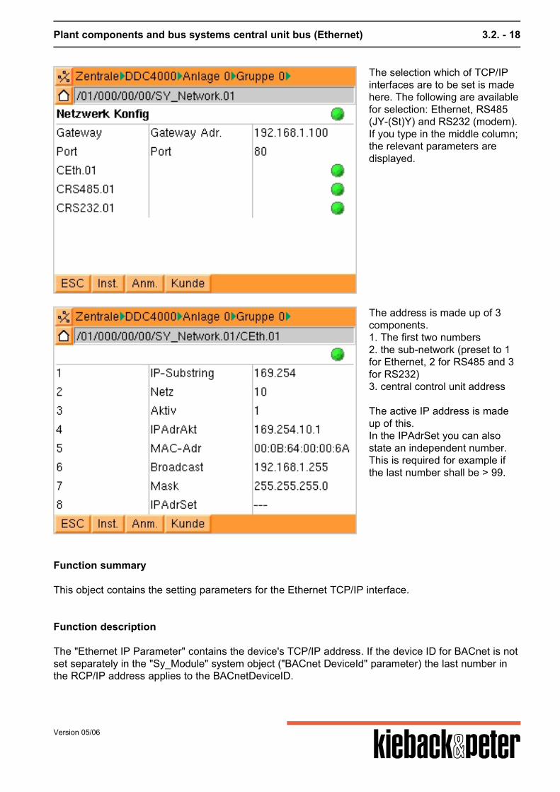
The selection which of TCP/IPinterfaces are to be set is madehere. The following are availablefor selection: Ethernet, RS485(JY-(St)Y) and RS232 (modem).If you type in the middle column;the relevant parameters aredisplayed.
The address is made up of 3components.1. The first two numbers2. the sub-network (preset to 1for Ethernet, 2 for RS485 and 3for RS232)3. central control unit address The active IP address is madeup of this.In the IPAdrSet you can alsostate an independent number.This is required for example ifthe last number shall be > 99.
Function summary
This object contains the setting parameters for the Ethernet TCP/IP interface.
Function description
The "Ethernet IP Parameter" contains the device's TCP/IP address. If the device ID for BACnet is notset separately in the "Sy_Module" system object ("BACnet DeviceId" parameter) the last number inthe RCP/IP address applies to the BACnetDeviceID.
Version 05/06
Plant components and bus systems central unit bus (Ethernet) 3.2. - 19
Example: 192.168.0.42 as an IP address, no separately assigned BACnetDeviceID, then "42" isthe BACnetDeviceID.
The network is switched on with the aid of the "Ethernet active" parameter. This starts the TCP/IPand BACnet drivers.
Parameters
No. name of parameter parameter typ min max init unit
Gateway GatewayGateway Addr.
set pointtext
-- -- 192.168.1.100 --
MACAdr MACAdr actual valuetext
-- -- 00:0B:64:00:00:00 --
Port UI-Server set pointinteger
0 65535 80 --
projNo PNProject Number
set pointtext
-- -- 000-00-00000 --
projSub PSProject SubNetwork
set pointtext
-- -- 1 --
3.2.3.2.2. Other DDC Central Units in the network
TCP/IP addresses of the DDC central control units
System object Sy_Host is used to set up the network.The TCP/IP addresses of the other DDC Central Units found in the central bus are entered in theparameters.The PS4000 makes the entry. Refer to objects -> system objects -> Sy_Host
3.2.3.2.3. Ethernet tests
Communication test
In order to for example check the connection between a laptop and a DDC4000 Central Unit youenter the following at the MS DOS entry request (Start --> Run... --> cmd.exe):
ping 172.20.11.75
Version 05/06
Plant components and bus systems central unit bus (Ethernet) 3.2. - 20
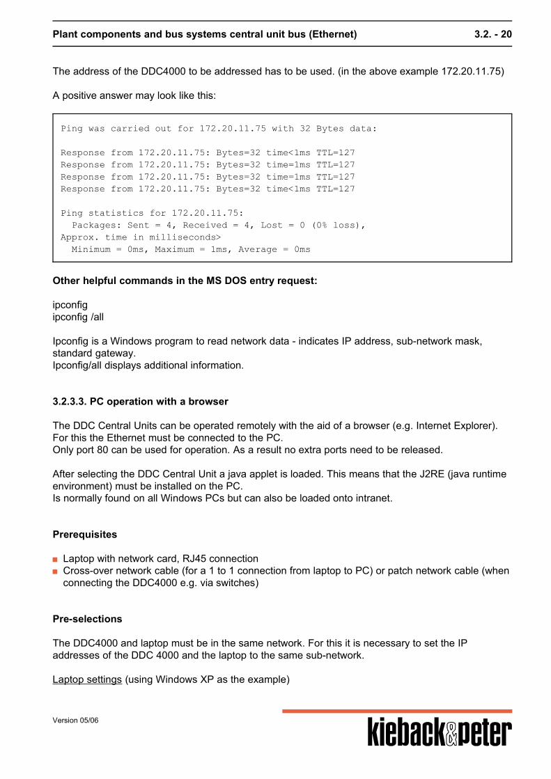
The address of the DDC4000 to be addressed has to be used. (in the above example 172.20.11.75) A positive answer may look like this:
Ping was carried out for 172.20.11.75 with 32 Bytes data:
Response from 172.20.11.75: Bytes=32 time<1ms TTL=127Response from 172.20.11.75: Bytes=32 time=1ms TTL=127Response from 172.20.11.75: Bytes=32 time=1ms TTL=127Response from 172.20.11.75: Bytes=32 time<1ms TTL=127
Ping statistics for 172.20.11.75: Packages: Sent = 4, Received = 4, Lost = 0 (0% loss),Approx. time in milliseconds> Minimum = 0ms, Maximum = 1ms, Average = 0ms
Other helpful commands in the MS DOS entry request: ipconfigipconfig /all Ipconfig is a Windows program to read network data - indicates IP address, sub-network mask,standard gateway.Ipconfig/all displays additional information.
3.2.3.3. PC operation with a browser
The DDC Central Units can be operated remotely with the aid of a browser (e.g. Internet Explorer).For this the Ethernet must be connected to the PC.Only port 80 can be used for operation. As a result no extra ports need to be released. After selecting the DDC Central Unit a java applet is loaded. This means that the J2RE (java runtimeenvironment) must be installed on the PC.Is normally found on all Windows PCs but can also be loaded onto intranet.
Prerequisites
Laptop with network card, RJ45 connection Cross-over network cable (for a 1 to 1 connection from laptop to PC) or patch network cable (when
connecting the DDC4000 e.g. via switches)
Pre-selections
The DDC4000 and laptop must be in the same network. For this it is necessary to set the IPaddresses of the DDC 4000 and the laptop to the same sub-network. Laptop settings (using Windows XP as the example)
Version 05/06
Plant components and bus systems central unit bus (Ethernet) 3.2. - 21
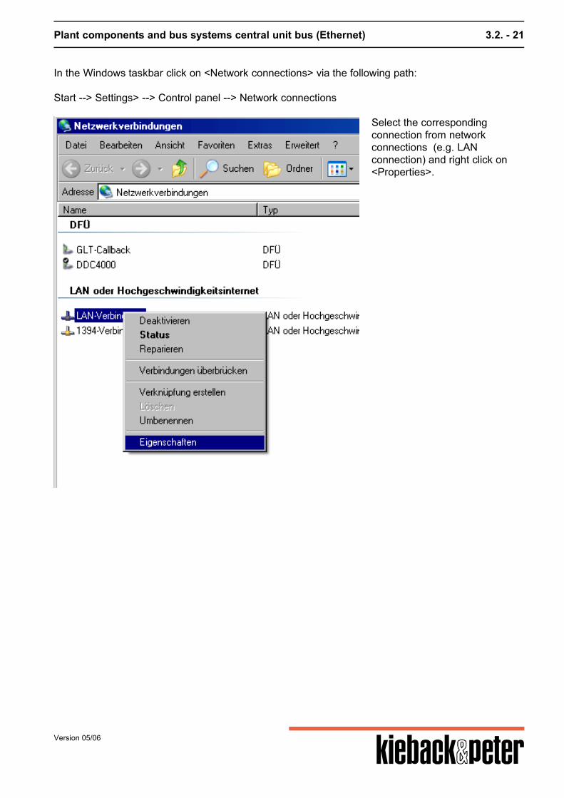
In the Windows taskbar click on <Network connections> via the following path: Start --> Settings> --> Control panel --> Network connections
Select the correspondingconnection from networkconnections (e.g. LANconnection) and right click on<Properties>.
Version 05/06

Plant components and bus systems central unit bus (Ethernet) 3.2. - 22
In the properties windowdisplayed click on the <Internetprotocol (TCP/IP)> elementunder <General> and click onproperties.
Version 05/06

Plant components and bus systems central unit bus (Ethernet) 3.2. - 23
A properties window for theinternet protocol (TCP/IP)opens. Click on the "Usefollowing IP address" option.
Enter the relevant IP address (e.g. 192.168.0.30) and the appropriate sub-network mask (e.g.255.255.255.0).For the example above the DDC4000's IP address may only contain 192.168.0.xxx forcommunication to be established. After changing a firmly assigned IP address the laptop must be restarted.
DDC4000 settings In the DDC4000 the IP address and sub-network mask must be adapted in the following parameters:
xx central unit 000 Module (Module 000) 00 plant (plant 0) 00 group (group 0) SY_Network.01 Object.Index EtIPAddr Parameter (IP address) EtMask Parameter (Sub-network mask) EtActive Parameter (switching the Ethernet to active in the DDC4000)
Version 05/06
Plant components and bus systems central unit bus (Ethernet) 3.2. - 24
The sub-network mask must be the same as in the laptop. The IP address must not be the same asin the laptop but must match the sub-network mask. The Ethernet must still be switched on via the<EtActive> parameter. Now it is possible to access the DDC4000 from the laptop via Explorer. To do so enter theDDC4000's IP address in the address field in Explorer. If it is not possible to access the DDC4000this may be due to the "Java 2 Runtime Environment" software not being installed on the laptop. Thissoftware must be installed and can be downloaded from the intranet from the following path:Documents --> Technical --> DDC4000 system --> Network technologyIt can also be found on the Internet by entering the search term "j2re".
The following link structure is used for opening:1. http://
Version 05/06
Plant components and bus systems central unit bus (Ethernet) 3.2. - 25
2. DDC TCP/IP address Sample central unit address 192.168.0.60: In Internet Explorer windowhttp://192.168.0.60
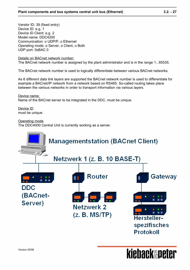
3.2.3.5. BMS connection
A BMS is connected via Ethernet to the DDC4000 system. As the BACnet communication is used forthis ensure that Port #BAC0 is switched freely throughout (router...). Caution! Version 1.0 and 1.1 do not contain BBMD (BACnet broadcast management device). Thismeans that communication via a router is not possible without an external BBMD. As a result of the native abilities of the DDC4000 it is also possible to switch to third party products.BACnet/IP is used. Please refer to the "Ethernet" chapter for the details of the Ethernet cabling and setting up BACnetcommunication. Please refer to the BMS documentation on installing and setting up the BMS. A modem can be connected to the serial interface. A connection to the BMS can be established viathe modem with PPP (point to point protocol).It is not possible to directly connect the BMS via the serial interface.
3.2.3.6. BACnet
A DDC4000 system parameter becomes a transportable parameter through a BACnet attachmentfunction. This occurs for example by selecting the desired parameters in the BMS or the relevantstipulations in the parameterizing tool.
What the DDC4000 can do
Medium: BACnet via EthernetEthernet (ISO8802-3)Ports: For hexadecimal range BAC0-BACF (47808 - 47823 dec.) The DDC4000 is a B-BC. The current PICS are found on the intranet.
Initial start-up
Ensure connection:Ethernet cable (1:1, patch cable) on the DDC to switch or routerEthernet cable (1:1, patch cable) from laptop to switch or router
Version 05/06
Plant components and bus systems central unit bus (Ethernet) 3.2. - 26
or Ethernet cable (cross-over) direct from DDC to laptop. Network settings:The customer must provide the settings even if the DDC network is not initially connected to thecustomer network it is advisable to obtain the setting data from the customer so that no addressconflicts occur when connection is made later.IP address: e.g. 192.168.8.60Network mask: e.g. 255.255.0.0Gateway: e.g. 172.20.11.75 Details on IP address:Certain addresses and address ranges are assigned special functions:127.0.0.1 - always the local computer/DDC 400010.x.x.x; 172.16.x.x - 172.31.x.x; 192.168.0.x - 192.168.255.x - private addresses that cannot makedirect connect with the Internet. In corporate networks addresses are normally selected from thisrange. These addresses require a gateway (networked computer with Internet connection) to be ableto communicate with the Internet. Details on network mask:This depends on the customer's corporate network and must be provided by him. Gateway details:The DDC4000 contacts the Internet or other networks via this computer or if this is not required theentry remains empty.
Use of routers BACnet/IP works with so-called UDP telegrams. These are not fed through by routers and firewalls.Thus no direct connection between BACnet clients in different network sections that are connectedvia routers or firewalls is possible. The use of a BBMD (BACnet Broadcast Management Device) can resolve this problem. A BBMDpackages broadcast messages in IP packages and sends these to a distance BBMD. Then a (local)broadcast is transmitted.The same procedure applies as appropriate for the response telegram - here the remote BBMDsends an IP package to the local BBMD. Only one BBMD may be used for each network section. Caution! No BBMD is contained in version 1.0.x and 1.1.x. Access to an external device is necessaryfor this.
BACnet settings
BACnet network number: e.g. 1Device name: e.g. DDC4000 serverDevice name client: e.g. DDC4000 clientVendor name: Kieback&Peter (fixed entry)
Version 05/06
Plant components and bus systems central unit bus (Ethernet) 3.2. - 27
Vendor ID: 39 (fixed entry)Device ID: e.g. 1Device ID Client: e.g. 2Model name: DDC4200Communication: o UDP/P, o EthernetOperating mode: o Server, o Client, o BothUDP port: 0xBAC 0 Details on BACnet network number:The BACnet network number is assigned by the plant administrator and is in the range 1...65535. The BACnet network number is used to logically differentiate between various BACnet networks. As 6 different data link layers are supported the BACnet network number is used to differentiate forexample a BACnet/IP network from a network based on RS485. So-called routing takes placebetween the various networks in order to transport information via various layers. Device name:Name of the BACnet server to be integrated in the DDC, must be unique. Device IDmust be unique. Operating modeThe DDC4000 Central Unit is currently working as a server.
Version 05/06
Plant components and bus systems central unit bus (Ethernet) 3.2. - 28
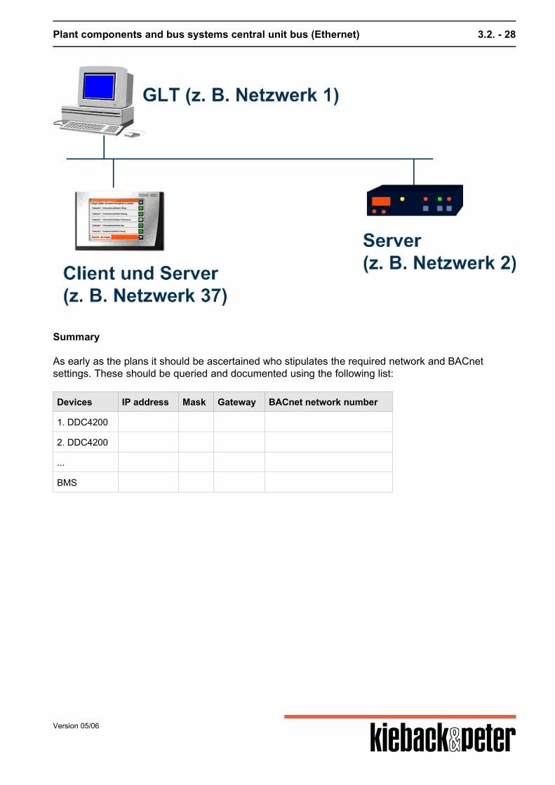
Summary
As early as the plans it should be ascertained who stipulates the required network and BACnetsettings. These should be queried and documented using the following list:
Devices IP address Mask Gateway BACnet network number
1. DDC4200
2. DDC4200
...
BMS
Version 05/06
Plant components and bus systems control cabinet bus 3.4. - 29
3.4. control cabinet bus
3.4.1. General
3.4.1.1. Installation
One peculiarity must be observed during installation: For the BMD and BMA bus modules the electricity supply and the CAN bus can be looped throughthe modules using a cascade plug.
3.4.1.3. Power supply
Performance data DDC4000
Device AC DC
BMD4032 90 mA 100 mA
BMD4064 90 mA 130 mA
BMA4024 280 mA
24 V DC inverse-polarity protection for all existing
3.4.2. BMA4024
Function summary
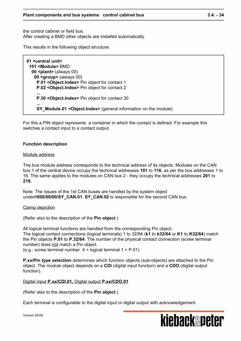
All functions of a bus module are summarized under a module of this type. Below the module several objects and their parameters exist to handle the sub-issues in the busmodule.The module is usually created via planning. This may also take place by logging on such a module tothe control cabinet or field bus.After creating a BMA4024 other objects are installed automatically. This results in the following object structure:
01 <central unit> 101 <Module> BMA4024 00 <plant> (always 00) 00 <group> (always 00) P.01 <Object.Index> Pin object for contact 1 P.02 <Object.Index> Pin object for contact 2 ... P.24 <Object.Index> Pin object for contact 24 SY_Module.01 <Object.Index> (general information on the module)
Version 05/06
Plant components and bus systems control cabinet bus 3.4. - 30
For this a PIN object represents a container in which the contact is defined. For example thisswitches a contact input to a contact output.
Function description
Module address The bus module address corresponds to the technical address of its object. Modules on the CAN bus1 of the central control unit occupy the technical addresses 101 to 116, according to the busaddresses 1 to 99. The same applies to the modules on CAN bus 2 - they occupy the technicaladdresses 201 to 216. Please note: The issues of the 1st CAN bus are handled by the system object under //000/00/00/SY_CAN.01. SY_CAN.02 is responsible for the 2nd CAN bus.
Clamp depiction (Refer also to the description of the Pin object.) All functions of a logical terminal are handled from the corresponding Pin object.The logical contact connections (logical terminals 1 to 24 (b1 to b24 or Y1 to Y24) match the Pinobjects P.01 to P.24. The number of the physical contact connection (screw terminal number) doesnot match a Pin object.(e.g.: screw terminal number 55 = logical terminal 1 = P.01) P.xx/Pin type selection determines which function objects are attached to the Pin object.
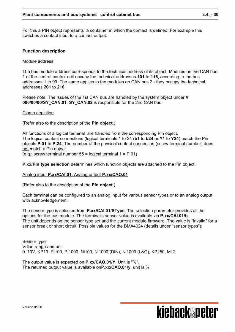
Analog input P.xx/CAI.01, Analog output P.xx/CAO.01 (Refer also to the description of the Pin object.) Each terminal can be configured to an analog input for various sensor types or to an analog outputwith acknowledgement. The sensor type is selected from P.xx/CAI.01/SType. The selection parameter provides all theoptions for the bus module. The terminal's sensor value is available via P.xx/CAI.01/b.The unit depends on the sensor type set and the current module firmware. The value is "invalid" for asensor break or short circuit. Possible values for the BMA4024 (details under "sensor types"): Sensor typeValue range and unit0..10V, KP10, Pt100, Pt1000, Ni100, Ni1000 (DIN), Ni1000 (L&G), KP250, ML2 The output value is expected on P.xx/CAO.01/Y. Unit is "%".The returned output value is available onP.xx/CAO.01/y, unit is %.
Version 05/06
Plant components and bus systems control cabinet bus 3.4. - 31
General parameters SY_Module.01 (Refer also to the description of the system objectSY_Module.) In SY_Module.01 the general parameters that each module offers are stored. Peculiarities:
899 = Version number of the firmware module Active = The module is reachable and has full function. (If the central unit loses contact with the
bus module, SY_Module.01/Active is set to 0.) DubAdr = The module notifies a double address. malfunction = The module notifies a malfunction. (If the module detects a malfunction itself sets
SY_Module.01/malfunction to 1 and provides and malfunction code to SY_Module.01/Err No.) ErrNo = malfunction code. Warnings and malfunction messages are coded here. The importance
can only be queried in the R&S.
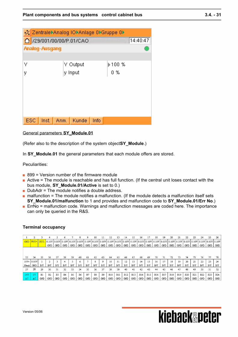
Terminal occupancy
Version 05/06
Plant components and bus systems control cabinet bus 3.4. - 32
3.4.3. BMD4032
Function summary
All functions of a bus module are summarized under a module of this type. Below the module several objects and their parameters exist to handle the sub-issues in the busmodule.The module is usually created via planning. This may also take place by logging on such a module tothe control cabinet or field bus.After creating a BMD other objects are installed automatically. This results in the following object structure:
01 <central unit> 101 <Module> BMD 00 <plant> (always 00) 00 <group> (always 00) P.01 <Object.Index> Pin object for contact 1 P.02 <Object.Index> Pin object for contact 2 ... P.30 <Object.Index> Pin object for contact 30 ... SY_Module.01 <Object.Index> (general information on the module)
For this a PIN object represents a container in which the contact is defined. For example thisswitches a contact input to a contact output.
Function description
Module address The bus module address corresponds to the technical address of its objects. Modules on the CANbus 1 of the central device occupy the technical addresses 101 to 116, as per the bus addresses 1 to16. The same applies to the modules on CAN bus 2 - they occupy the technical addresses 201 to216. Note: The issues of the 1st CAN buses are handled by the system objectunder//000/00/00/SY_CAN.01. SY_CAN.02 is responsible for the second CAN bus.
Clamp depiction (Refer also to the description of the Pin object.) All logical terminal functions are handled from the corresponding Pin object.The logical contact connections (logical terminals) 1 to 32/64 (k1 to k32/64 or K1 to K32/64) matchthe Pin objects P.01 to P.32/64. The number of the physical contact connection (screw terminalnumber) does not match a Pin object.(e.g.: screw terminal number 4 = logical terminal 1 = P.01)
Version 05/06
Plant components and bus systems control cabinet bus 3.4. - 33
P.xx/Pin type selection determines which function objects (sub-objects) are attached to the Pinobject. The module object depends on a CDI (digital input function) and a CDO (digital outputfunction).
Digital input P.xx/CDI.01, Digital output P.xx/CDO.01 (Refer also to the description of the Pin object.) Each terminal is configurable to the digital input or digital output with acknowledgement. The digital input value is available from P.xx/CDI.01/k. The output value is expected onP.xx/CDO.01/K. The returned value from the output is available on P.xx/CDO.01/k.
General parameters SY_Module.01 (Refer also to the description of the system objectSY_Module.) In SY_Module.01 the general parameters that each module offers are stored. Peculiarities:
899 = Version number of the firmware module Active = The module is reachable and has full function. (If the central unit loses contact with the
bus module SY_Module.01/Active is set to 0.) DubAdr = The module notifies a double address. malfunction = The module notifies a malfunction. (If the module detects a malfunction itself it sets
SY_Module.01/malfunction to 1 and provides and malfunction code to SY_Module.01/Err No.) ErrNo = malfunction code. Warnings and malfunction messages are coded here. The importance
can only be queried in the R&S.
Terminal occupancy
3.4.4. BMD4064
Function summary
All functions of a bus module are summarized under a module of this type. Below the module several objects and their parameters exist to handle the sub-issues in the busmodule.The module is usually created via planning. This may also take place by logging on such a module to
Version 05/06
Plant components and bus systems control cabinet bus 3.4. - 34
the control cabinet or field bus.After creating a BMD other objects are installed automatically. This results in the following object structure:
01 <central unit> 101 <Module> BMD 00 <plant> (always 00) 00 <group> (always 00) P.01 <Object.Index> Pin object for contact 1 P.02 <Object.Index> Pin object for contact 2 ... P.30 <Object.Index> Pin object for contact 30 ... SY_Module.01 <Object.Index> (general information on the module)
For this a PIN object represents a container in which the contact is defined. For example thisswitches a contact input to a contact output.
Function description
Module address The bus module address corresponds to the technical address of its objects. Modules on the CANbus 1 of the central device occupy the technical addresses 101 to 116, as per the bus addresses 1 to16. The same applies to the modules on CAN bus 2 - they occupy the technical addresses 201 to216. Note: The issues of the 1st CAN buses are handled by the system objectunder//000/00/00/SY_CAN.01. SY_CAN.02 is responsible for the second CAN bus.
Clamp depiction (Refer also to the description of the Pin object.) All logical terminal functions are handled from the corresponding Pin object.The logical contact connections (logical terminals) 1 to 32/64 (k1 to k32/64 or K1 to K32/64) matchthe Pin objects P.01 to P.32/64. The number of the physical contact connection (screw terminalnumber) does not match a Pin object.(e.g.: screw terminal number 4 = logical terminal 1 = P.01) P.xx/Pin type selection determines which function objects (sub-objects) are attached to the Pinobject. The module object depends on a CDI (digital input function) and a CDO (digital outputfunction).
Digital input P.xx/CDI.01, Digital output P.xx/CDO.01 (Refer also to the description of the Pin object.) Each terminal is configurable to the digital input or digital output with acknowledgement.
Version 05/06
Plant components and bus systems control cabinet bus 3.4. - 35
The digital input value is available from P.xx/CDI.01/k. The output value is expected onP.xx/CDO.01/K. The returned value from the output is available on P.xx/CDO.01/k.
General parameters SY_Module.01 (Refer also to the description of the system objectSY_Module.) In SY_Module.01 the general parameters that each module offers are stored. Peculiarities:
899 = Version number of the firmware module Active = The module is reachable and has full function. (If the central unit loses contact with the
bus module SY_Module.01/Active is set to 0.) DubAdr = The module notifies a double address. malfunction = The module notifies a malfunction. (If the module detects a malfunction itself it sets
SY_Module.01/malfunction to 1 and provides and malfunction code to SY_Module.01/Err No.) ErrNo = malfunction code. Warnings and malfunction messages are coded here. The importance
can only be queried in the R&S.
Terminal occupancy
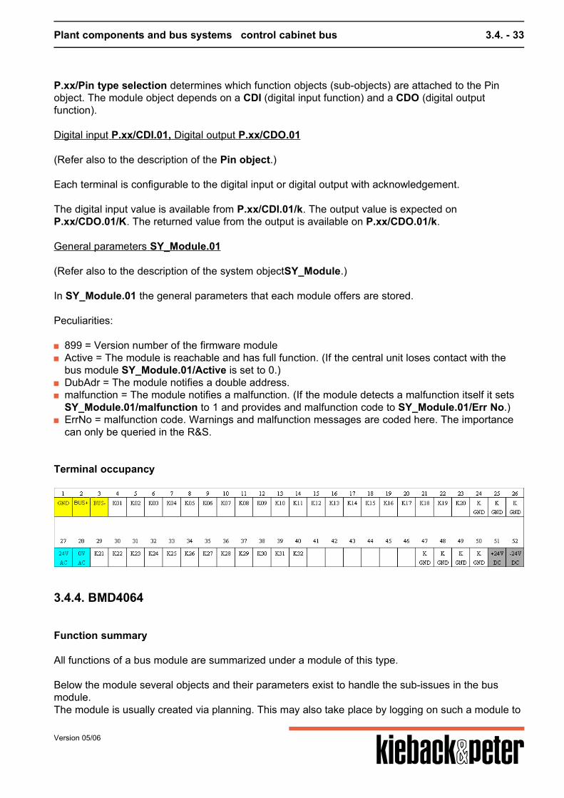
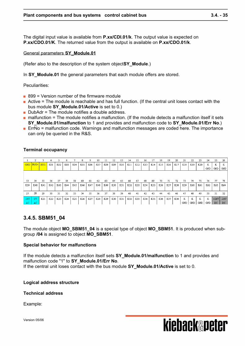
3.4.5. SBM51_04
The module object MO_SBM51_04 is a special type of object MO_SBM51. It is produced when sub-group /04 is assigned to object MO_SBM51. Special behavior for malfunctions If the module detects a malfunction itself sets SY_Module.01/malfunction to 1 and provides andmalfunction code "1" to SY_Module.01/Err No.If the central unit loses contact with the bus module SY_Module.01/Active is set to 0.
Logical address structure
Technical address Example:
Version 05/06
Plant components and bus systems control cabinet bus 3.4. - 36
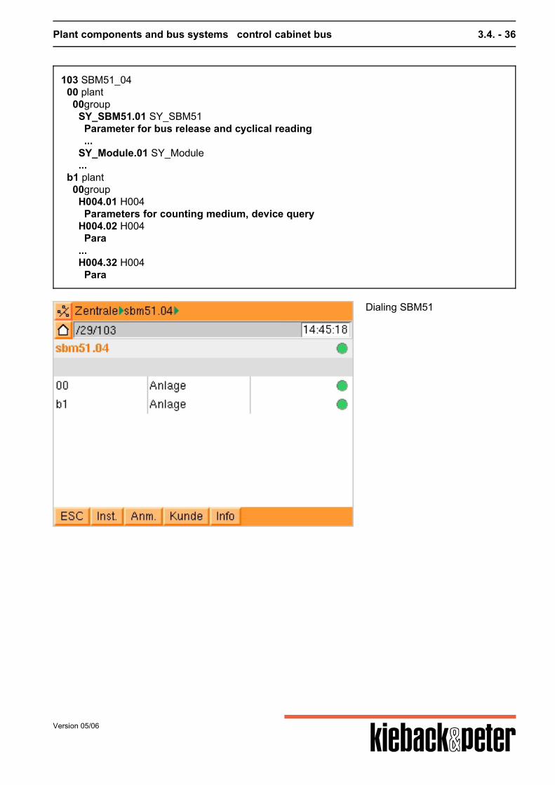
103 SBM51_04 00 plant 00group SY_SBM51.01 SY_SBM51 Parameter for bus release and cyclical reading ... SY_Module.01 SY_Module ... b1 plant 00group H004.01 H004 Parameters for counting medium, device query H004.02 H004 Para ... H004.32 H004 Para
Dialing SBM51
Version 05/06
Plant components and bus systems control cabinet bus 3.4. - 37
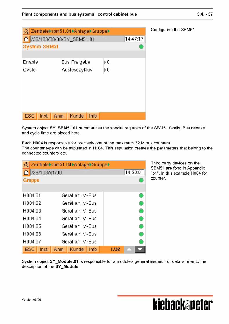
Configuring the SBM51
System object SY_SBM51.01 summarizes the special requests of the SBM51 family. Bus releaseand cycle time are placed here. Each H004 is responsible for precisely one of the maximum 32 M bus counters.The counter type can be stipulated in H004. This stipulation creates the parameters that belong to theconnected counters etc.
Third party devices on theSBM51 are fond in Appendix"b1". In this example H004 forcounter.
System object SY_Module.01 is responsible for a module's general issues. For details refer to thedescription of the SY_Module.
Version 05/06
Plant components and bus systems control cabinet bus 3.4. - 38
technical bus address
Module bus address on the SBM bus //xxx The bus module address corresponds to the technical address of its objects. Modules on the CANbus 1 of the central device occupy the technical addresses 101 to 116, as per the bus addresses 1 to99. The same applies to the modules on CAN bus 2 - they occupy the technical addresses 201 to216. Note: The issues of the 1st CAN buses are handled by the system objectunder//000/00/00/SY_CAN.01. SY_CAN.02 is responsible for the second CAN bus. Selection of specific SBM51 //xxx/00/00/SY_SBM51.01/Config Module SBM51/04 is selected. Another device can be selected. This should be done carefully as it isnot possible to check for an appropriate SBM device! The SBM device itself only supplies theinformation that it is a SBM51 but not whether it is a SBM51/04 or another device. M bus counter bus address //xxx/b1/00/H004.yy 32 gateway objects type H004 are created as a SBM51/04 can process up to 32 M bus counters.Each gateway object is responsible for one M bus counter.The bus address is expressed in the gateway object index. The SBM51/04 only supports the M buscounters with addresses from 1 to 32 although the M bus knows addresses from 1 to 250.
Function description of object //xxx/00/00/SY_SBM51.01
Special SBM51 parameter: SY_SBM51.01 In SY_SBM51.01 all parameters are stored that are important for the SBM51 as a whole but are toospecial for the SY_Module.
Config = Select the specific SBM51 for which the module object is responsible.The selection is now on SMB51/04.
Enable = Bus release Cycle = Bus cycle time. 0 = 24h, 1 = 2min.
(Compare description of the system objectSY_SBM51.)
Version 05/06
Plant components and bus systems control cabinet bus 3.4. - 39
Function description of the device objects //xxx/b1/00/H004.yy
M bus counter with bus address yy: //xxx/b1/00/H004.yy Each object is responsible for exactly one M bus counter.
Config = Selection of consumption medium.After selection a second Config parameter is visible from the following one.
Config EL = Selection of an electricity counter from a list.Parameter becomes visible if the medium "electricity" is selected with Config.
Config WM = Selection of a heat volume counter from a list.Parameter becomes visible if the medium "heat" is selected with Config.
Config WA = Selection of a water counter from a list.Parameter becomes visible if the medium "water" is selected with Config.
(Compare description of gateway object H004.)
Function summary
Jedes installierte Objekt ist für genau ein Gerät am M-Bus zuständig. Der Objekt-Index dertechnischen Adresse ist mit der Busadresse am M-Bus identisch. Über den Parameter Config wirddie Geräte-Klasse des konkreten M-Bus-Zählers ausgewählt, woraufhin ein zweiter Config-Parameter"ConfigYY" installiert wird, über den der Geräte-Typ ausgewählt wird. Aufgrund beider Auswahlenwird ein passendes Subobjekt installiert. ConfigYY steht für ConfigEL, ConfigWA oder ConfigWM.Siehe dort. Die Subobjekte CD_WM und CD_WA stehen für die "Generischen Parameter" derGeräte-Klasse, das sind die Parameter, die wirklich jeder Wäremzähler bzw. jeder Wasserzählerbieten sollte. Alle anderen Subobjekte haben mehr Parameter als nur die generischen.
Parameters
No. name of parameter parameter typ min max init unit
Active aktivDevice active
actual valueboolean
-- -- 0 --
Anfrage Counter inquiry set pointboolean
-- -- 0 --
Config MediumCounting medium
set pointmultistate
-- 5 0 value,text0,none1,Electricity counter2,Heat counter3,Water counter4,DDC3000-Menu
ConfigEL Elt-TypElt-Counter type
set pointmultistate
-- 2 0 value,text0,Standard1,Standard-Maximum
Version 05/06

Plant components and bus systems control cabinet bus 3.4. - 40
No. name of parameter parameter typ min max init unit
ConfigWA H²O-TypWater counter type
set pointmultistate
-- 3 0 value,text0,Standard1,Standard-Maximum2,Allmeas ISWZ
ConfigWM WMZ-TypHeat counter type
set pointmultistate
-- 2 0 value,text0,Standard1,Standard-Maximum
Version 05/06

Plant components and bus systems Field bus 3.5. - 41
3.5. Field bus
3.5.1. General
3.5.2. Modules
The field bus modules of the DDC3000 system are integrated step by step into the DDC4000 system.They are subject to the same connection conditions and wiring guidelines. These modules only"understand" an address assignment up to 63.The circular or intranet state which modules have already been integrated.
Version 05/06
Software structure 4. - 42
4. Software structure
4. Software structure ....................................................................................................................... 42
4.1. General, background ................................................................................................................. 484.1.1. Addressing ................................................................................................................................ 484.1.1.1. Addressing examples ............................................................................................................ 534.1.2. Parameter types ....................................................................................................................... 564.1.3. Object principles ....................................................................................................................... 60
4.2. Basic functions .......................................................................................................................... 624.2.1. central unit address .................................................................................................................. 624.2.2. Time administration .................................................................................................................. 624.2.2.1. S118 Schedule ...................................................................................................................... 624.2.3. Behind the front cover ............................................................................................................... 644.2.4. Units .......................................................................................................................................... 66
4.3. Objects ........................................................................................................................................ 724.3.1. General ..................................................................................................................................... 724.3.2. Software objects ....................................................................................................................... 724.3.2.1. What are software objects? ................................................................................................... 724.3.2.2. All software objects ................................................................................................................ 744.3.2.3. S066 limiting value ................................................................................................................. 774.3.2.4. S083 Arithmetic ..................................................................................................................... 794.3.2.5. S126 MMM storage ................................................................................................................ 824.3.2.9. S238 Basic program PID (ventilation) ................................................................................... 844.3.2.9.1. S301 Y limitation ................................................................................................................. 904.3.2.9.2. S302 Y set .......................................................................................................................... 974.3.2.9.3. S303 Cascade .................................................................................................................. 1004.3.2.9.4. S304 start up switching ..................................................................................................... 1054.3.2.9.5. S305 Optimization ventilation ........................................................................................... 1094.3.2.9.6. S306 Free night cooling .................................................................................................... 1124.3.2.9.7. S307 Constant frost protection ......................................................................................... 1174.3.2.9.8. S308 Minimum room temperature .................................................................................... 1204.3.2.9.9. S309 Standstill .................................................................................................................. 1224.3.2.9.10. S310 Energy selection .................................................................................................... 1254.3.2.9.11. S311 Sequence change ................................................................................................. 1294.3.2.9.12. S312 Limitation ............................................................................................................... 1304.3.2.9.13. S313 SP switching .......................................................................................................... 1364.3.2.9.14. S314 Set point glide ........................................................................................................ 139
Version 05/06
Software structure 4. - 43
4.3.2.9.15. S315 Set point correction ............................................................................................... 1424.3.2.9.16. S316 Set point remote control ........................................................................................ 1454.3.2.9.17. S317 XP switching .......................................................................................................... 1484.3.2.10. S239 Basic program heating ............................................................................................. 1504.3.2.10.1. Graphical summaries ...................................................................................................... 1584.3.2.10.2. S300 Optimization .......................................................................................................... 1614.3.2.10.3. S301 Y limitation ............................................................................................................. 1684.3.2.10.4. S302 Y set ...................................................................................................................... 1754.3.2.10.5. S312 Limitation ............................................................................................................... 1784.3.2.10.6. S313 SP switching .......................................................................................................... 1844.3.2.10.7. S315 Set point correction ............................................................................................... 1874.3.2.10.8. S316 Set point remote control ........................................................................................ 1904.3.2.10.9. S317 XP switching .......................................................................................................... 1934.3.2.10.10. S318 Room correction .................................................................................................. 1954.3.2.10.11. S319 Standby ............................................................................................................... 1984.3.2.10.12. S348 Adaptive heating curve ........................................................................................ 2014.3.2.11. S321 Enthalpy ................................................................................................................... 2044.3.2.12. S322 Sequence ................................................................................................................. 2054.3.2.13. S323 Binary valuation ........................................................................................................ 2084.3.2.14. S324 Scaling ...................................................................................................................... 2104.3.2.15. S325 MinMaxAverage ........................................................................................................ 2134.3.2.16. S326 Time gliding .............................................................................................................. 2154.3.2.17. S327 Pulse counting .......................................................................................................... 2184.3.2.18. S328 Operation hours ........................................................................................................ 2204.3.2.19. S329 Heat volume P .......................................................................................................... 2214.3.2.20. S330 Heat volume DT ....................................................................................................... 2234.3.2.21. S333 Ring counter ............................................................................................................. 2264.3.2.22. S334 Spreadsheet function ............................................................................................... 2294.3.2.23. S335 Sensor switching ...................................................................................................... 2324.3.2.24. S337 Basic program fixed value ........................................................................................ 2334.3.2.25. S338 Gliding ...................................................................................................................... 2374.3.2.26. S342 Pulse output ............................................................................................................. 2384.3.2.27. S343 E-Max ....................................................................................................................... 2404.3.2.28. S344 Degree daily figure ................................................................................................... 2514.3.2.29. S347 E-Max French ........................................................................................................... 2524.3.2.30. S901 Signal generator ....................................................................................................... 2644.3.3. Hardware objects .................................................................................................................... 2664.3.3.1. What are hardware objects? ................................................................................................ 2664.3.3.2. All hardware objects ............................................................................................................ 268
Version 05/06
Software structure 4. - 44
4.3.3.3. Priorities and signals ............................................................................................................ 2704.3.3.4. Command execution check CEC ......................................................................................... 2714.3.3.5. Operating hours ................................................................................................................... 2724.3.3.6. Malfunction catch ................................................................................................................. 2734.3.3.7. Malfunction message output ................................................................................................ 2744.3.3.8. H301 Steam moistening unit constant ................................................................................. 2754.3.3.10. H401 Electrical air heater single stage .............................................................................. 2814.3.3.11. H402 Electrical air heater 2 stage ..................................................................................... 2864.3.3.12. H403 Electrical air heater 3 stage ..................................................................................... 2934.3.3.13. H404 Electrical air heater constant .................................................................................... 3004.3.3.14. H501 Cover open/closed ................................................................................................... 3054.3.3.15. H502 Fire protection cover with drive ................................................................................ 3094.3.3.16. H503 Cover 3-point ............................................................................................................ 3144.3.3.17. H504 Cover constant ......................................................................................................... 3174.3.3.18. H601 Fan single stage ....................................................................................................... 3204.3.3.19. H602 Fan 2 stage .............................................................................................................. 3264.3.3.21. H604 fan constant FC/bypass ........................................................................................... 3344.3.3.22. H611 Valve open/closed .................................................................................................... 3414.3.3.23. H612 Valve bus drive ......................................................................................................... 3464.3.3.24. H613 Valve 3-point ............................................................................................................ 3494.3.3.25. H614 Valve constant .......................................................................................................... 3534.3.3.26. H701 Burner single stage .................................................................................................. 3564.3.3.27. H702 Burner 2 stage .......................................................................................................... 3634.3.3.28. H703 Burner modulating 3 point ........................................................................................ 3714.3.3.29. H704 Burner modulating .................................................................................................... 3794.3.3.30. H801 Volume flow regulator constant ................................................................................ 3874.3.3.31. H802 Volume flow regulator constant ................................................................................ 3914.3.3.32. H901 Pump single stage ................................................................................................... 3944.3.3.33. H903 Pump variable transformer ....................................................................................... 4014.3.3.34. H904 Pump BUS ............................................................................................................... 4094.3.3.35. H905 Double pump ............................................................................................................ 4134.3.4. Basic objects (flags, timers, AE, AA, BE, BA) ........................................................................ 4214.3.4.1. BO L - Lamp ........................................................................................................................ 4214.3.4.2. BO M - Markers ................................................................................................................... 4224.3.4.3. BO P - Pin ............................................................................................................................ 4244.3.4.4. BO S - Switches ................................................................................................................... 4264.3.4.5. BO S_11 - Switch single stage ON/OFF ............................................................................. 4264.3.4.6. BO S_12 - Confirmation switch ........................................................................................... 4274.3.4.7. BO S_21 - 2 push-button MANUAL/AUTO, ON/OFF .......................................................... 427
Version 05/06
Software structure 4. - 45
4.3.4.8. BO S_22 2 push-buttons AUTO, Manual On ....................................................................... 4284.3.4.9. BO S_23 (as 22) .................................................................................................................. 4284.3.4.10. BO S_31 - 3 push-buttons AUTO, Manual off, Manual on ................................................ 4294.3.4.11. BO S_32 - 3 push-buttons AUTO/manual, Level1 ON/OFF, Level 2 ON/OFF ................. 4294.3.4.12. BO S_41 - 4 Push-buttons AUTO, OFF, Manual Level 1, Level 2 .................................... 4304.3.4.13. BO S_42 - 4 Push-buttons AUTO, DAY, NIGHT, OFF ..................................................... 4314.3.4.14. BO S_51 - 5 Push-buttons Auto, off, Manual Level 1, 2, 3 ............................................... 4314.3.4.15. BO T - Timer ...................................................................................................................... 4324.3.5. System objects ....................................................................................................................... 4334.3.5.1. System objects .................................................................................................................... 4334.3.5.2. SY_Module Module settings general ................................................................................... 4354.3.5.3. SY_Config plant configuration ............................................................................................. 4364.3.5.4. SY_CAN CAN bus ............................................................................................................... 4384.3.5.7. SY_Host ............................................................................................................................... 4404.3.5.8. SY_FAX ............................................................................................................................... 4414.3.5.9. SY_MsgMan ........................................................................................................................ 4424.3.5.10. SY_EMAIL ......................................................................................................................... 4424.3.5.11. Sy_Clock ............................................................................................................................ 4434.3.5.12. SY_Serial ........................................................................................................................... 4444.3.5.13. Sy_ModConf ...................................................................................................................... 4454.3.5.14. SY_Network ....................................................................................................................... 4464.3.6. Attachment functions .............................................................................................................. 4484.3.6.1. F001 Scaling ........................................................................................................................ 4494.3.6.3. F003 Limitation .................................................................................................................... 4514.3.6.4. F004 catch ........................................................................................................................... 4514.3.6.5. F005 Command execution check ........................................................................................ 4514.3.6.6. F006 Damping ..................................................................................................................... 4524.3.6.7. F007 Delay ........................................................................................................................... 4534.3.6.9. F017 Object status .............................................................................................................. 4534.3.6.12. FSelMO Selection message set ........................................................................................ 4544.3.6.13. FAIMO Sensor monitoring ................................................................................................. 4564.3.6.14. Set parameters .................................................................................................................. 4574.3.6.14.1. FSource .......................................................................................................................... 4574.3.6.14.3. F013 Simulation value .................................................................................................... 4574.3.6.14.4. F014 Test value .............................................................................................................. 4584.3.6.15. BACnet function objects .................................................................................................... 4584.3.6.15.1. FB_AI analog input ......................................................................................................... 4584.3.6.15.2. FB_AO analog output ..................................................................................................... 4594.3.6.15.3. FB_AV analog parameters ............................................................................................. 459
Version 05/06
Software structure 4. - 46
4.3.6.15.4. FB_BI binary input .......................................................................................................... 4604.3.6.15.5. FB_BO binary output ...................................................................................................... 4604.3.6.15.6. FB_BV binary parameters .............................................................................................. 4604.3.6.15.7. FB_MI multistate input .................................................................................................... 4614.3.6.15.8. FB_MO multistate output ................................................................................................ 4614.3.6.15.9. FB_MV multistate parameters ........................................................................................ 4624.3.7. Sub-objects ............................................................................................................................. 4624.3.7.1. Sub-objects .......................................................................................................................... 4624.3.7.2. CAI analog input .................................................................................................................. 4644.3.7.3. CAO analog output .............................................................................................................. 4644.3.7.4. CDI binary input ................................................................................................................... 4654.3.7.5. CDO binary output ............................................................................................................... 4654.3.7.6. CModMO .............................................................................................................................. 4654.3.8. Device objects ........................................................................................................................ 4664.3.8.1. Gateway Objects ................................................................................................................. 4664.3.8.2. Volume counter .................................................................................................................... 4664.3.8.2.1. CD_WA volume counter ................................................................................................... 4664.3.8.2.2. CD_WA Volume counter 01 ............................................................................................. 4674.3.8.2.3. CD_WA Volume counter 02 ............................................................................................. 4674.3.8.3. Electrical counter ................................................................................................................. 4684.3.8.3.1. CD_WM Electrical counter ............................................................................................... 4684.3.8.3.2. CD_WM Electrical counter 01 .......................................................................................... 4684.3.8.4. SBMs ................................................................................................................................... 4694.3.8.4.1. SBM51 .............................................................................................................................. 469
4.4. parameterizing ......................................................................................................................... 4714.4.1. Plant structuring ...................................................................................................................... 4714.4.1.1. Plants ................................................................................................................................... 4714.4.1.2. Groups ................................................................................................................................. 4714.4.2. Malfunction message management ........................................................................................ 4714.4.2.1. Plant messages ................................................................................................................... 4714.4.2.1.1. Messages ......................................................................................................................... 4714.4.2.1.3. Message memory SY_MsgMan ........................................................................................ 4744.4.2.1.4. Output definition SY_MsgOut ........................................................................................... 4754.4.2.1.5. Selection message set FSelMO ....................................................................................... 4764.4.2.1.6. Sensor failure message FAIMO ....................................................................................... 4784.4.2.1.7. Modem configuration SY_ModConf .................................................................................. 4794.4.2.1.10. Plant status - signalizing ................................................................................................. 4814.4.2.1.11. SMS ................................................................................................................................ 4824.4.2.1.12. Email ............................................................................................................................... 483
Version 05/06
Software structure 4. - 47
4.4.2.1.13. Fax recipient SY_FAX .................................................................................................... 4844.4.2.2. Plant messages ................................................................................................................... 4854.4.3. Creating the customer interface ............................................................................................. 4864.4.4. Integrating touch screen switches .......................................................................................... 4884.4.5. Manual analysis ...................................................................................................................... 4904.4.6. Converting multistate to binary ............................................................................................... 4914.4.7. Network return ........................................................................................................................ 493
4.5. Service level, data (restore) backup, updates ...................................................................... 4954.5.1. Service level ............................................................................................................................ 4954.5.1.1. Service level, access to parameterizing .............................................................................. 4954.5.1.2. User administration .............................................................................................................. 4964.5.2. Import data, backups, software updates ................................................................................ 4974.5.2.1. Cold start, warm start, reset ................................................................................................ 4974.5.2.2. Import data - PS4000 .......................................................................................................... 4984.5.2.3. Data (restore) backup CF card ............................................................................................ 5044.5.2.4. Data format .......................................................................................................................... 5074.5.2.5. Plant software update .......................................................................................................... 5074.5.2.6. Update bootloader ............................................................................................................... 508
Version 05/06
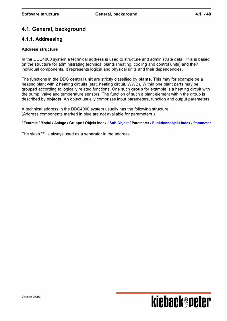
Software structure General, background 4.1. - 48
4.1. General, background
4.1.1. Addressing
Address structure
In the DDC4000 system a technical address is used to structure and administrate data. This is basedon the structure for administrating technical plants (heating, cooling and control units) and theirindividual components. It represents logical and physical units and their dependencies. The functions in the DDC central unit are strictly classified by plants. This may for example be aheating plant with 2 heating circuits (stat. heating circuit, WWB). Within one plant parts may begrouped according to logically related functions. One such group for example is a heating circuit withthe pump, valve and temperature sensors. The function of such a plant element within the group isdescribed by objects. An object usually comprises input parameters, function and output parameters. A technical address in the DDC4000 system usually has the following structure:(Address components marked in blue are not available for parameters.)
The slash "/" is always used as a separator in the address.
Version 05/06
Software structure General, background 4.1. - 49
Version 05/06
Software structure General, background 4.1. - 50
Version 05/06
Software structure General, background 4.1. - 51
More detailed explanation Address element <central unit>The central unit is the first element in the technical address. It can have a value in the range between1 and 99. If this address element is not stated the own central unit is addressed. The "/" separator isretained before the individual central unit and module address elements. This results in the address:"//Module"
Value Notes
01...99 If your own central device is to be address "//" is enough for central addressing
Address element <Module>The second address element in the technical address is the module address. There are various valueranges for this element and their meaning is shown in the following table. Each module has a uniquenumber within its central device.
Value Notes
000 Address the central unit module DDC4000 itself (controls, regulators, plant information)
001...099 internal modules e.g. I/O card 1 = 001
101...199 Module addresses for the 1st CAN bus; 101...116 for S-Bus; 101...163 (future plans 101...199) forF-Bus
201...299 Module addresses for the 2nd CAN bus; 201..0.216 for S-Bus; 201..0.263 (future plans 201..0.299)for F-Bus
Address element <plant>The plant is the third element in the technical address. It can have a value in the range between 0and 99.
Value Notes
00 Used to transfer to the DDC4000's plant information or to achieve lower hierarchy addresses.
01...99 Stating the plants within the module.
Address element <Group>The group address is an organizational criterion within one module. It can be used in any way. Valuesbetween 0 and 99 are permitted here. The number of a group is unique within a module. Eachmodule has as standard the group with number 00.
Values Notes
00...99 Free order unit (containers). It contains one or more objects.
Address element <Object.Index>The unique address of an object is combined out of the address of the object type and the objectindex. The address element "object" describes the object type. The object type can be availablerepeatedly in one group. The uniqueness of the object within the group is guaranteed by the object
Version 05/06
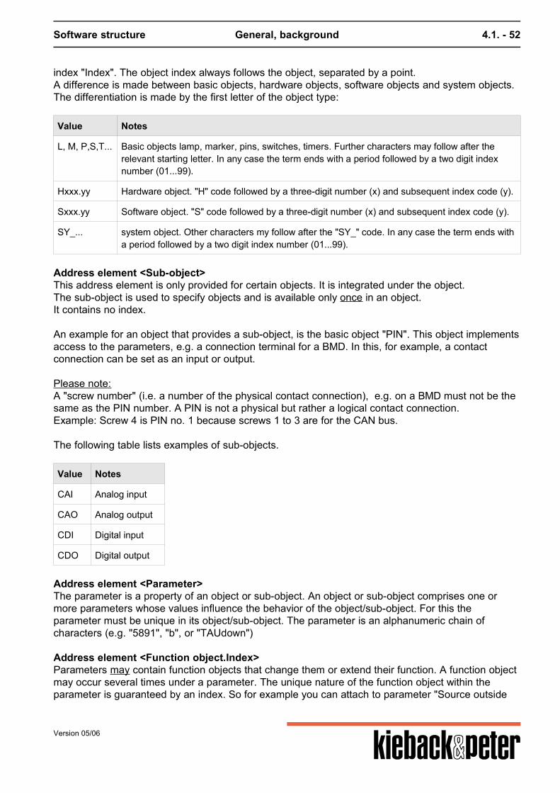
Software structure General, background 4.1. - 52
index "Index". The object index always follows the object, separated by a point.A difference is made between basic objects, hardware objects, software objects and system objects.The differentiation is made by the first letter of the object type:
Value Notes
L, M, P,S,T... Basic objects lamp, marker, pins, switches, timers. Further characters may follow after therelevant starting letter. In any case the term ends with a period followed by a two digit indexnumber (01...99).
Hxxx.yy Hardware object. "H" code followed by a three-digit number (x) and subsequent index code (y).
Sxxx.yy Software object. "S" code followed by a three-digit number (x) and subsequent index code (y).
SY_... system object. Other characters my follow after the "SY_" code. In any case the term ends witha period followed by a two digit index number (01...99).
Address element <Sub-object>This address element is only provided for certain objects. It is integrated under the object.The sub-object is used to specify objects and is available only once in an object.It contains no index. An example for an object that provides a sub-object, is the basic object "PIN". This object implementsaccess to the parameters, e.g. a connection terminal for a BMD. In this, for example, a contactconnection can be set as an input or output. Please note:A "screw number" (i.e. a number of the physical contact connection), e.g. on a BMD must not be thesame as the PIN number. A PIN is not a physical but rather a logical contact connection.Example: Screw 4 is PIN no. 1 because screws 1 to 3 are for the CAN bus. The following table lists examples of sub-objects.
Value Notes
CAI Analog input
CAO Analog output
CDI Digital input
CDO Digital output
Address element <Parameter>The parameter is a property of an object or sub-object. An object or sub-object comprises one ormore parameters whose values influence the behavior of the object/sub-object. For this theparameter must be unique in its object/sub-object. The parameter is an alphanumeric chain ofcharacters (e.g. "5891", "b", or "TAUdown")
Address element <Function object.Index>Parameters may contain function objects that change them or extend their function. A function objectmay occur several times under a parameter. The unique nature of the function object within theparameter is guaranteed by an index. So for example you can attach to parameter "Source outside
Version 05/06
Software structure General, background 4.1. - 53
temperature" (5103) in the basic heating program a "Source" (FSource) function object in order totransfer the source value to parameter 5103.
Address element <parameter> of the function objectThe parameter is a property of the function object. A function object is comprised of one or moreparameters whose value influence the behavior of the function object. For this the parameter must beunique in its function object. The parameter is an alphanumeric chain of characters (e.g. "s")
4.1.1.1. Addressing examples
Example 1:access to parameter "command" e.g. for backing up data Central unitFor central unit 01:/01 ModuleAccess to data backup is provided in the DDC4000 system information:/01/000 PlantAccess to the data backup is through plant 00:/01/000/00 GroupAccess to data backup is through group 00:/01/000/00/00 Object.IndexAccess to data backup is guaranteed by object SY_Datsi:/01/000/00/00/SY_Datsi.01 Sub-objectNo sub-object is required for access to the "command" parameter. Therefore no sub-object is used. ParametersAccess to the "command" parameter:/01/000/00/00/SY_Datsi.01/Command Function object.IndexA function object is not required for access to the "command" parameter Parameter (of the function object)A function object parameter is not required for access to the "command" parameter Example 2:Access to the "s" parameter as the source address for a "Q TO" parameter in basic heating program
Version 05/06
Software structure General, background 4.1. - 54
Central unitFor central unit 02:/02 ModuleAccess to the basic heating program is by regulating/controlling the DDC4000 and thus via Module000:/02/000 PlantAccess to the basic heating program is via the selection of for example a heating plant (01):/02/000/01 GroupAccess to the basic heating program is via the selection of for example a group control (01):/02/000/01/01 Object.IndexAccess to the basic heating program :/02/000/01/01/S239.01 Sub-objectThe source is located in the function object of the "Q TO" parameter in the basic heating programobject. Therefore no sub-object is addressed. ParametersAccess to the "Q TO" parameter of object S239.01 (Basic heating program):/02/000/01/01/S239.01/5103 Function object.IndexA function object that extends or changes the properties or includes additional functions is attachedto this "Q TO" parameter (e.g. stipulating a source for the value in the "Q TO" parameter):/02/000/01/01/S239.01/5103/FSource.01 Parameter (of the function object)You can stipulate the properties of the function object etc. with these parameters. In the exampleparameter "s" is access and this contains the source address of the analog value :/02/000/01/01/S239.01/5103/FSource.01/s Example 3:Access to a "b" parameter in the PIN object as analog input from the DDC4000 analog card Central unitFor central unit 03:/03 ModuleAccess to the analog card of the DDC4000 is via the module address 001:/03/001
Version 05/06

Software structure General, background 4.1. - 55
PlantThe analog card itself has no plants so plant 0 is selected (access to the PINs always via plant 0):/03/001/00 GroupThe analog card itself has no group so group 0 is selected (access to the PINs always via group 0):/03/001/00/00 Object.IndexAccess to the PIN object and therefore to the logical contact connection:/03/001/00/00/P.01 Sub-objectThe PIN object contains a sub-object. This PIN is therefore defines as an analog input (CAI):/03/001/00/00/P.01/CAI ParametersAccess to the "b" parameter where the analog value is located:/03/001/00/00/P.01/CAI/b Function object.IndexA function object is not required for access to the "b" parameter Parameter (of the function object)A function object parameter is not required for access to the "b" parameter Example 4:Access to the "101" parameter (message output) of the function object "message set" of a PIN one.g. a BMD4032 Central unitFor central unit 04:/04 ModuleAccess to the BMD 4032 that is installed on the 1st CAN bus and as the first module:/04/101 PlantA BMD itself has no plant so plant 0 is selected (access to the PINs always via plant 0):/04/101/00 GroupA BMD itself has no group so group 0 is selected (access to the PINs always via group 0):/04/101/00/00 Object.IndexAccess to the PIN object and therefore to the logical contact connection (e.g. pin 1):/04/101/00/00/P.01
Version 05/06
Software structure General, background 4.1. - 56
Sub-objectThe pin object contains a sub-object. This pin is therefore defined as a digital input (CAI):/04/101/00/00/P.01/CDI ParametersAccess to the parameter "k" in which the digital logical contact status is displayed:/04/101/00/00/P.01/CDI/k Function object.IndexA function object is attached to this "k" parameter that extends or changes the properties or containsadditional function (e.g. outputs a message in the DDC4000 if the binary value changes from "0" to"1"):/04/101/00/00/P.01/CDI/k/FSelMO.01 Parameter (of the function object)You can stipulate for example the properties of the function object with these parameters. In theexample parameter "101" is accessed and this contains the source address of the analog value:/04/101/00/00/P.01/CDI/k/FSelMO.01/101
4.1.2. Parameter types
For parameterizing each object has a certain number of parameters. These parameters are shown intabular form. The types used are described in greater detail here. Can the parameters be deleted? In many cases a function is switched to inactive in this way. Source or not? A source can be linked to each parameter in the DDC4000. The value of the source then replaces theparameter value.In line with the importance some typical parameters always require source parameterizing. Thenames of these are marked with the supplement "source" or "Q". This should make locating themeasier. Summary IntegerFloating comma digitBinary value (Boolean)MultistateSelection listStringReference
Version 05/06
Software structure General, background 4.1. - 57
Integer
The integer type has a maximum range of -2,147,483,648 to 2,147,483,647. As this size can not beachieved in practice the value "infinity" is given in the table if this value range is not restricted.A typical example of the integer type is operating hours. These are only recorded in full hours.Example:
Par.No Parameter name Description Parametertype
Min Max Init Unit
9 BhOperating hours
Operating hours counter level 1 and/orlevel 2
Set pointInteger
0 +infinity 0 h
Explanation of statements: Par.No9 Parameter number: This number is used to address the parameter within the object. This number isnot unique in the whole system! Parameter nameBhBh ges. Parameter name: A difference is made between basic text (here "Bh") and default text (here"operating hours"). The basic text can be a maximum of 8 characters and can be used foraddressing. The default text is 15 characters long and provides a longer description. This descriptioncan be adapted to the customer's wishes. Descriptionset point/actual value for counting operating hours level 1 and/or level 2 The description gives information on the importance and use of the parameter as well as anypeculiarities to be observed. Parameter typeSet pointInteger Two pieces of information are included in the "parameter type". In the top line the term " set point" or"actual value" is found. This states whether it is a stipulated (target) value or a calculated (actual)value. As a result actual values can not be changed directly by the user.The second line contains the parameter type, e.g. "integer" or "string". Min0 Min states the minimum value permitted (here 0). Sometimes this states the limitation from the DDC'stechnological perspective and thus not every permitted value is always appropriate. Max
Version 05/06
Software structure General, background 4.1. - 58
+infinity Max state the maximum permitted value (here +infinity = 2,147,483,647 which corresponds to245,000 years) that is permitted for this parameter. Init0 The value stated under "Init" matches the default for the first installation of the relevant object. Herethe "0" means that the operating hours counter starts to count at "0" if it is not overwritten with adifferent value. Unith The unit is only stated when this is appropriate. In this case "h" stands for "hours". This documentalso includes a list of units.
Float
The float (or floating point) type has a maximum range of -3.402823466E38 to 3.402823466E38 (E38stands for 10 to the power of 38 or seen in a different way the comma is shifted 38 positions to theright). As this size can not be achieved in practice the value "infinity" is given in the table if this valuerange is not restricted.A typical example of the float type is outside temperature. This is only recorded in °C with 3characters after the decimal point (as for all floating numbers) and is indicated with one characterafter the point (varies with parameter).Here a fictitious example:
Par.No Parameter name Description Parameter type Min Max Init Unit
5103 TOTO
Outside temperature Actual valueFloating commanumber
-999.000 999.000 0.000 ---
For general information on the states, refer to integer (above).
Binary value / Boolean
A binary value can only have the value 0 "false" or 1 "true". The corresponding meaning can be verydifferent and must be taken from the documentation.
Multistate
A multistate value can depict several statuses in a parameter. So for example a controller can havethe status ON, OFF or AUTO.
Version 05/06
Software structure General, background 4.1. - 59
Par.No Parameter name Description Parameter type Min Max Init Unit
5175 Source remote control -- Actual valueStatus value
-- 4 1 BACnet,DDC_No.,Text4, 0, OFF2, 1, day1, 9, Auto3, 35, night
The information on the status value are more complex and so they are worth handling in greaterdetail: The "unit" column lists a small table that shows the potential statuses. Here the first column("BACnet" title" states the numbering of the statuses as used in BACnet. The BACnet standardprescribes the numbering of the available statuses from 1 consecutively to n (number of statuses).This does not match the approach at Kieback&Peter. The Kieback&Peter numbering is found in the second column (title "DDC no."). For Kieback&Peternumbering the same numbers always have the same meaning, which can mean that the number 0,1and 9 (for OFF, ON, AUTO) are used. The importance is to be read in the third column (status text). The table is sorted by the Kieback&Peter numbering. The "Init" column states the preset status. This is BACnet numbering! The "Max" column indicates the highest BACnet index.
Selection list
A selection list enables you to choose from several statuses for a parameter.Example:
Par.No Parameter name Description Parameter type Min Max Init Unit
5127 Uncontrolled condition -- Set pointpull list
-- -- 0 Selection listBitPos,Text0, YL11, YL22, YL33, YL4
For this the parameter is viewed in its binary depiction form. A bit (bit position) is used for eachstatus. In this example this means when YL2 and YL are to be selected:binary: 0110 = decimal: 6 If YL1, YL2 and YL3 are to be selected this looks as follows:binary: 0111 = decimal: 7
Version 05/06
Software structure General, background 4.1. - 60
If you are unfamiliar with this depiction of numbers the Windows calculator (found under accessories)may help as long as it is switched to "scientific". The default setting (column "Init") "0" means that no status is selected.
String
The "string" parameter type is always used when none of the other types offer adequate options. Sothis is used for telephone numbers (e.g. "+49-30-60095-0") or IP addresses (e.g. 192.168.0.1).
Source/Reference
In a reference parameter type addresses that point to other parameters from where the value is to beobtained are entered.
4.1.3. Object principles
The following image presents the key objects with a potential type of connection and use.
Version 05/06
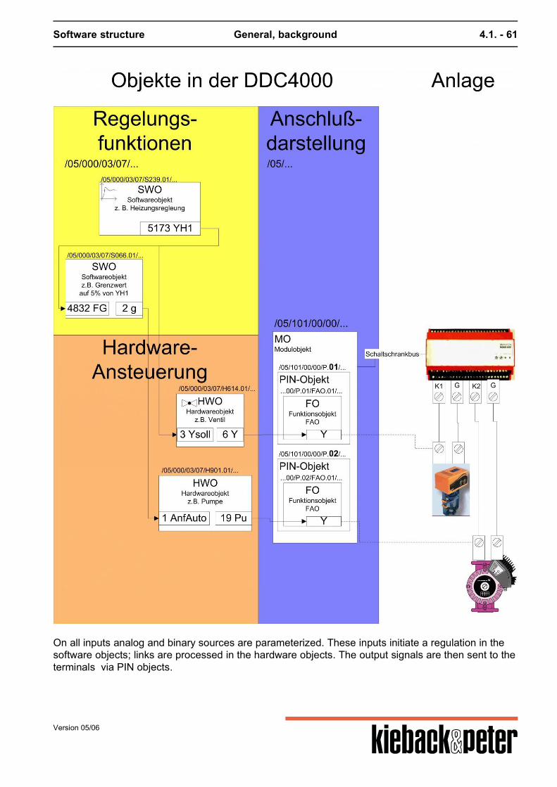
Software structure General, background 4.1. - 61
On all inputs analog and binary sources are parameterized. These inputs initiate a regulation in thesoftware objects; links are processed in the hardware objects. The output signals are then sent to theterminals via PIN objects.
Version 05/06
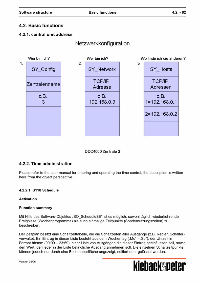
Software structure Basic functions 4.2. - 62
4.2. Basic functions
4.2.1. central unit address
4.2.2. Time administration
Please refer to the user manual for entering and operating the time control, the description is writtenhere from the object perspective.
4.2.2.1. S118 Schedule
Activation
Function summary
Mit Hilfe des Software-Objektes „SO_ScheduleSE“ ist es möglich, sowohl täglich wiederkehrendeEreignisse (Wochenprogramme) als auch einmalige Zeitpunkte (Sondernutzungszeiten) zubeschreiben. Der Zeitplan besitzt eine Schaltzeittabelle, die die Schaltzeiten aller Ausgänge (z.B. Regler, Schalter)verwaltet. Ein Eintrag in dieser Liste besteht aus dem Wochentag („Mo“ - „So“), der Uhrzeit imFormat hh:mm (00:00 – 23:59), einer Liste von Ausgängen die dieser Eintrag beeinflussen soll, sowieden Wert, den jeder in der Liste befindliche Ausgang annehmen soll. Die einzelnen Schaltzeitpunktekönnen jedoch nur durch eine Bedienoberfläche angezeigt, editiert oder gelöscht werden.
Version 05/06

Software structure Basic functions 4.2. - 63
Version 05/06
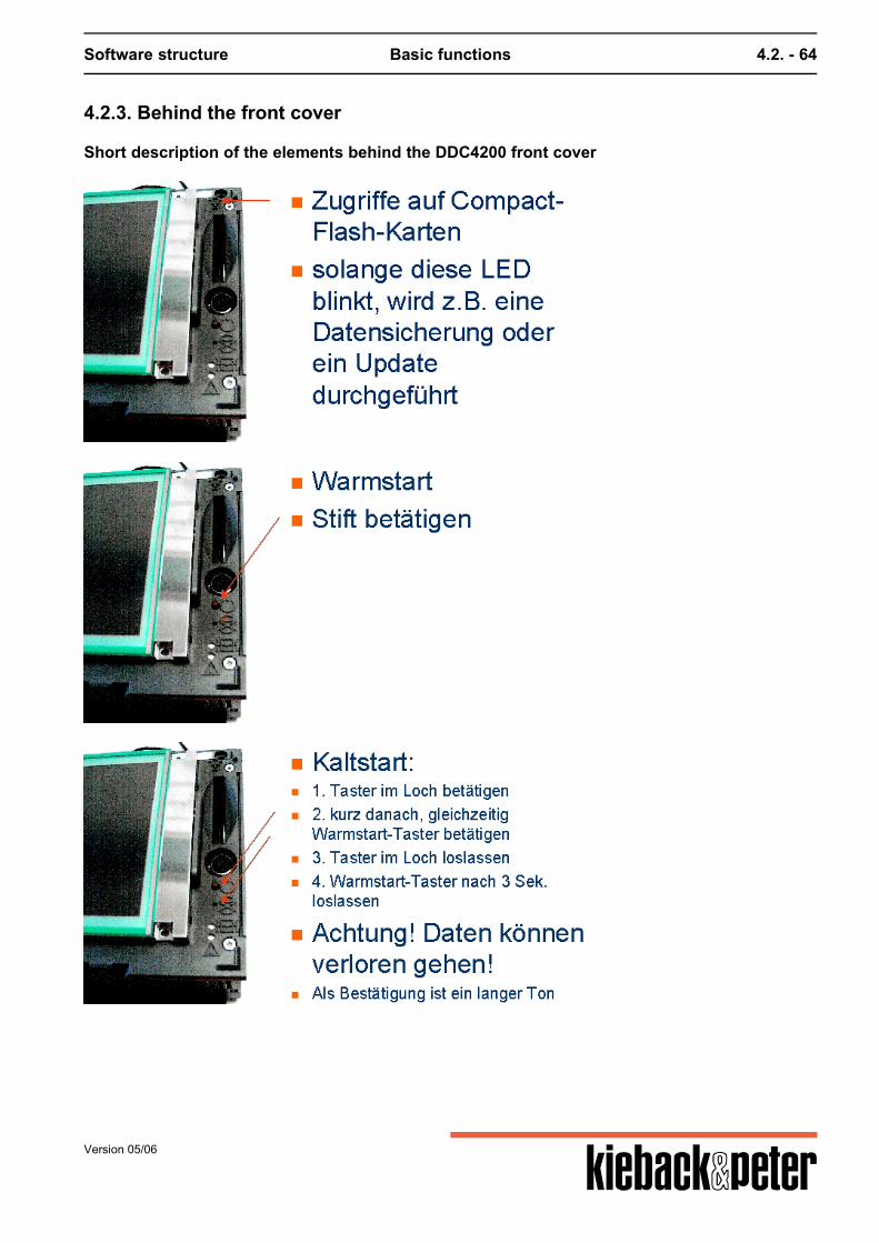
Software structure Basic functions 4.2. - 64
4.2.3. Behind the front cover
Short description of the elements behind the DDC4200 front cover
Version 05/06
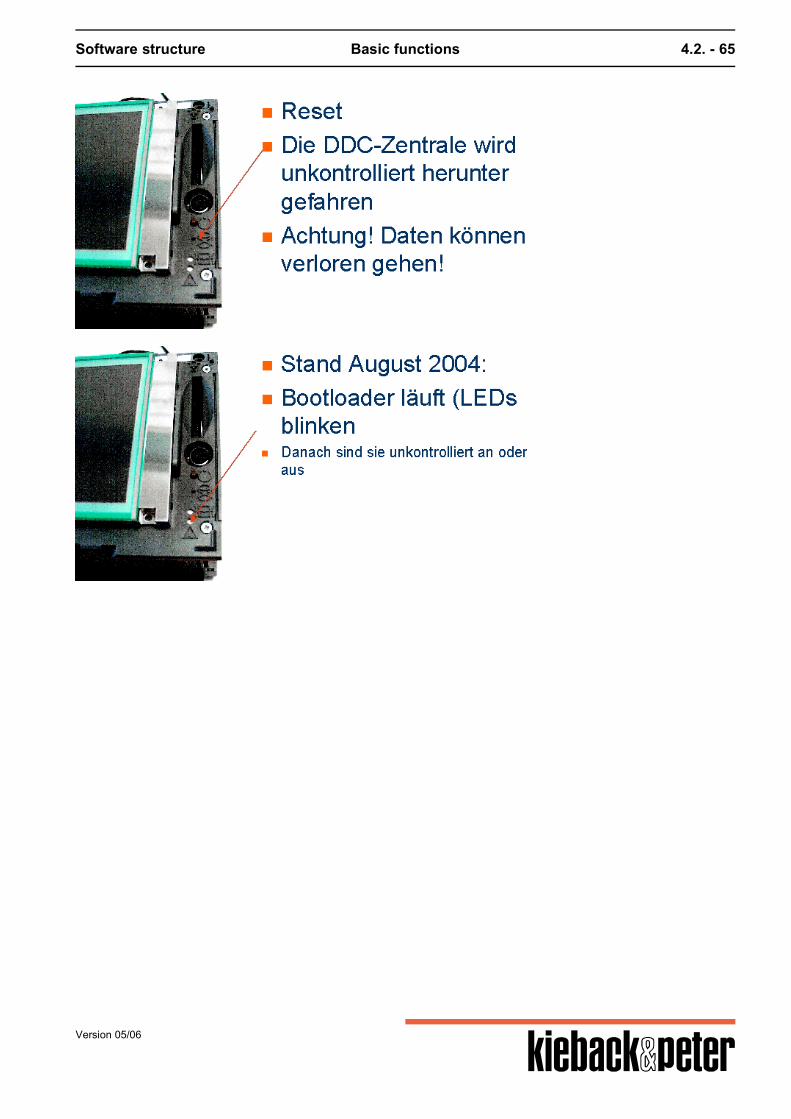
Software structure Basic functions 4.2. - 65
Version 05/06
Software structure Basic functions 4.2. - 66
4.2.4. Units
Summary of usable units in the DDC
No. unit description
0 m² Quadratmeter [m2]
1 ft² square-feet [ft2]
2 mA Milliampere [mA]
3 A Ampere [A]
4 Ω Ohm
5 V Volt (V)
6 kV Kilovolt (kV)
7 MV Megavolt (MV)
8 VA Volt Ampere (VA)
9 kVA Kilovolt Ampere (kVA)
10 MVA Megavolt amperes
11 VA Reac Volt amperes reactive
12 KA Reac Kilovolt amperes reactive
13 MVA Reac Megavolt ampere reactive
14 cos φ Degrees phase (Phasenverschiebung)
16 J Joule (J)
17 kJ Kilojoule (KJ)
18 Wh Watt-Stunden (Wh)
19 kWh Kilowatt-Stunden (KWh)
20 BTU BTUs
22 ton h Tonnen-Stunden
23 J/kg dry air Joule pro Kg tockener Luft
24 BTU/p dry air btu per pound dry air
25 1/h Zyklen pro Stunde
26 1/min Zyklen pro Minute
27 Hz Hertz (Hz)
28 g H²O/kg Gramm Wasser pro Kilogramm trockener Luft
29 % Relative Feuchte (%rF)
Version 05/06
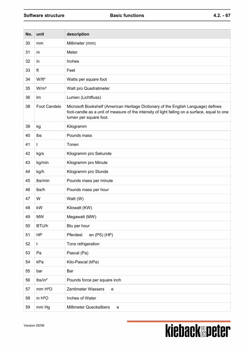
Software structure Basic functions 4.2. - 67
No. unit description
30 mm Millimeter (mm)
31 m Meter
32 in Inches
33 ft Feet
34 W/ft² Watts per square foot
35 W/m² Watt pro Quadratmeter
36 lm Lumen (Lichtfluss)
38 Foot Candels Microsoft Bookshelf (American Heritage Dictionary of the English Language) definesfoot-candle as a unit of measure of the intensity of light falling on a surface, equal to onelumen per square foot.
39 kg Kilogramm
40 lbs Pounds mass
41 t Tonen
42 kg/s Kilogramm pro Sekunde
43 kg/min Kilogramm pro Minute
44 kg/h Kilogramm pro Stunde
45 lbs/min Pounds mass per minute
46 lbs/h Pounds mass per hour
47 W Watt (W)
48 kW Kilowatt (KW)
49 MW Megawatt (MW)
50 BTU/h Btu per hour
51 HP Pferdest en (PS) (HP)
52 t Tons refrigeration
53 Pa Pascal (Pa)
54 kPa Kilo-Pascal (kPa)
55 bar Bar
56 lbs/in² Pounds force per square inch
57 mm H²O Zentimeter Wassers e
58 in H²O Inches of Water
59 mm Hg Millimeter Quecksilbers e
Version 05/06
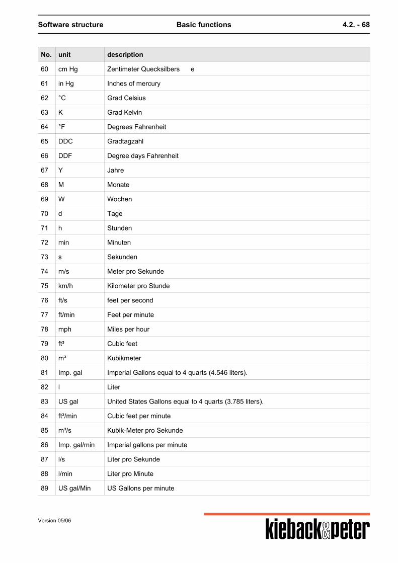
Software structure Basic functions 4.2. - 68
No. unit description
60 cm Hg Zentimeter Quecksilbers e
61 in Hg Inches of mercury
62 °C Grad Celsius
63 K Grad Kelvin
64 °F Degrees Fahrenheit
65 DDC Gradtagzahl
66 DDF Degree days Fahrenheit
67 Y Jahre
68 M Monate
69 W Wochen
70 d Tage
71 h Stunden
72 min Minuten
73 s Sekunden
74 m/s Meter pro Sekunde
75 km/h Kilometer pro Stunde
76 ft/s feet per second
77 ft/min Feet per minute
78 mph Miles per hour
79 ft³ Cubic feet
80 m³ Kubikmeter
81 Imp. gal Imperial Gallons equal to 4 quarts (4.546 liters).
82 l Liter
83 US gal United States Gallons equal to 4 quarts (3.785 liters).
84 ft³/min Cubic feet per minute
85 m³/s Kubik-Meter pro Sekunde
86 Imp. gal/min Imperial gallons per minute
87 l/s Liter pro Sekunde
88 l/min Liter pro Minute
89 US gal/Min US Gallons per minute
Version 05/06
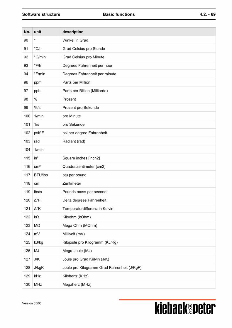
Software structure Basic functions 4.2. - 69
No. unit description
90 ° Winkel in Grad
91 °C/h Grad Celsius pro Stunde
92 °C/min Grad Celsius pro Minute
93 °F/h Degrees Fahrenheit per hour
94 °F/min Degrees Fahrenheit per minute
96 ppm Parts per Million
97 ppb Parts per Billion (Milliarde)
98 % Prozent
99 %/s Prozent pro Sekunde
100 1/min pro Minute
101 1/s pro Sekunde
102 psi/°F psi per degree Fahrenheit
103 rad Radiant (rad)
104 1/min
115 in² Square inches [inch2]
116 cm² Quadratzentimeter [cm2]
117 BTU/lbs btu per pound
118 cm Zentimeter
119 lbs/s Pounds mass per second
120 Δ°F Delta degrees Fahrenheit
121 Δ°K Temperaturdifferenz in Kelvin
122 kΩ Kiloohm (kOhm)
123 MΩ Mega Ohm (MOhm)
124 mV Millivolt (mV)
125 kJ/kg Kilojoule pro Kilogramm (KJ/Kg)
126 MJ Mega-Joule (MJ)
127 J/K Joule pro Grad Kelvin (J/K)
128 J/kgK Joule pro Kilogramm Grad Fahrenheit (J/KgF)
129 kHz Kilohertz (KHz)
130 MHz Megaherz (MHz)
Version 05/06
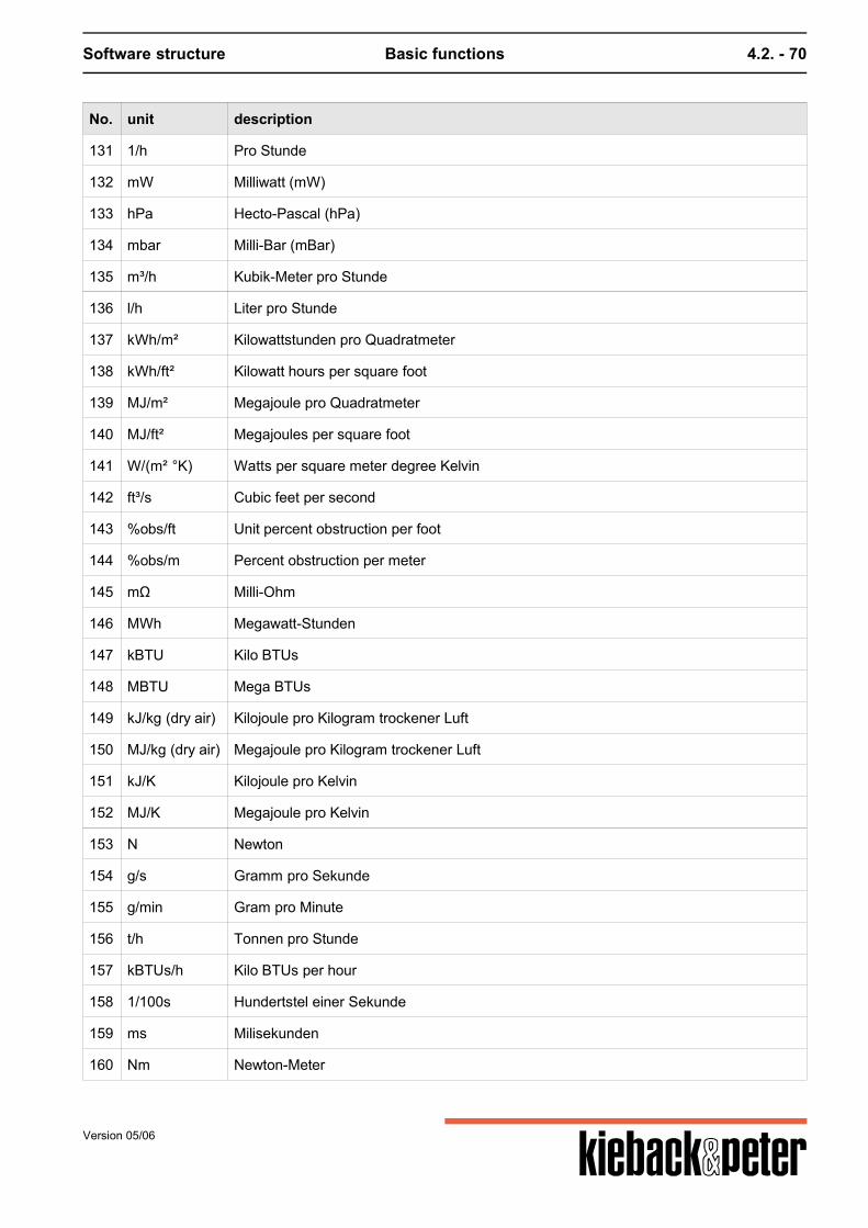
Software structure Basic functions 4.2. - 70
No. unit description
131 1/h Pro Stunde
132 mW Milliwatt (mW)
133 hPa Hecto-Pascal (hPa)
134 mbar Milli-Bar (mBar)
135 m³/h Kubik-Meter pro Stunde
136 l/h Liter pro Stunde
137 kWh/m² Kilowattstunden pro Quadratmeter
138 kWh/ft² Kilowatt hours per square foot
139 MJ/m² Megajoule pro Quadratmeter
140 MJ/ft² Megajoules per square foot
141 W/(m² °K) Watts per square meter degree Kelvin
142 ft³/s Cubic feet per second
143 %obs/ft Unit percent obstruction per foot
144 %obs/m Percent obstruction per meter
145 mΩ Milli-Ohm
146 MWh Megawatt-Stunden
147 kBTU Kilo BTUs
148 MBTU Mega BTUs
149 kJ/kg (dry air) Kilojoule pro Kilogram trockener Luft
150 MJ/kg (dry air) Megajoule pro Kilogram trockener Luft
151 kJ/K Kilojoule pro Kelvin
152 MJ/K Megajoule pro Kelvin
153 N Newton
154 g/s Gramm pro Sekunde
155 g/min Gram pro Minute
156 t/h Tonnen pro Stunde
157 kBTUs/h Kilo BTUs per hour
158 1/100s Hundertstel einer Sekunde
159 ms Milisekunden
160 Nm Newton-Meter
Version 05/06
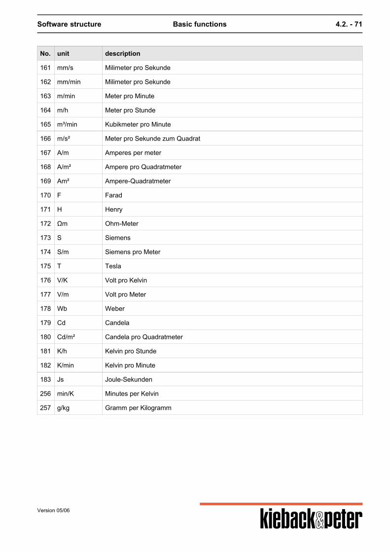
Software structure Basic functions 4.2. - 71
No. unit description
161 mm/s Milimeter pro Sekunde
162 mm/min Milimeter pro Sekunde
163 m/min Meter pro Minute
164 m/h Meter pro Stunde
165 m³/min Kubikmeter pro Minute
166 m/s² Meter pro Sekunde zum Quadrat
167 A/m Amperes per meter
168 A/m² Ampere pro Quadratmeter
169 Am² Ampere-Quadratmeter
170 F Farad
171 H Henry
172 Ωm Ohm-Meter
173 S Siemens
174 S/m Siemens pro Meter
175 T Tesla
176 V/K Volt pro Kelvin
177 V/m Volt pro Meter
178 Wb Weber
179 Cd Candela
180 Cd/m² Candela pro Quadratmeter
181 K/h Kelvin pro Stunde
182 K/min Kelvin pro Minute
183 Js Joule-Sekunden
256 min/K Minutes per Kelvin
257 g/kg Gramm per Kilogramm
Version 05/06
Software structure Objects 4.3. - 72
4.3. Objects
4.3.1. General
Objects are consistently used in the DDC4000. This applies both for producing the firmware and forthe plant structure and projecting. The objects visible in the service interface are classified to aid the technician with a betterclarification.
Software objectsAre functions that regulate the DDC Central Unit. These include for example the basic programsPID and heating and separate objects such as arithmetic.The basic programs were summarized by function. All software functions that are directly related tothe GP PID are found under object number S238. This includes for example the cascade or Y limit.The parameters that are part of such functions are collected in folders and are therefore offered inthe service level.
Hardware objectsare summarized functions that are used to control plant parts.
Basic objectsBasic objects are for example timer, marker, switches and the terminals of modules - the PINs.
system objectsThese are functions that are processed in the central unit. In general they are not directly related tothe plant. The system objects include for example setting the date and time or IP configuration.
Other objects exist within the object structure:
Attachment functions(also called function objects). It is possible to attach functions to each parameter on the plant thatchange these parameters (e.g. scaling) or expand their function (e.g. source, BACnet object).Therefore the attachment functions are found below or on the parameters.
Sub-objectsThese objects are used to more precisely describe an object. A key example a PIN. Each clamp inthe plant is represented by a PIN. This PIN can be stipulated by a sub-object on an input or output,digital or analog.You also find sub-objects within the SBM51.
4.3.2. Software objects
4.3.2.1. What are software objects?
Software objects are summaries of control functions in a block with input and output values. TheDDC4000 Central Units' software objects mainly match the menus of the DDC3000 system. Thefunctions are summarized in unchangeable and tested blocks.
Version 05/06
Software structure Objects 4.3. - 73
The basic programs were summarized by function. All software functions that are directly related tothe GP PID are found under object number S238. This includes for example the cascade or Y limit.The parameters that are part of such functions are collected in folders and are therefore offered inthe service level.
Parameters, names and classification
Parameters can be addressed in two different ways.1. via the parameter number and 2. via the parameter name.The parameter number is unique to only one object. Each object can have for example a parameterwith the number 12 and the text "Rep". For this addressing is possible in sources and links both vialanguage-unattached parameters and via parameter names. The use of texts instead of numbers isadvantageous for planning plant assignments and when reading sources. However for the software objects the numbering of the DDC3000 menu was used. A customer-specific plain text can also be set for the relevant parameter.
Version 05/06
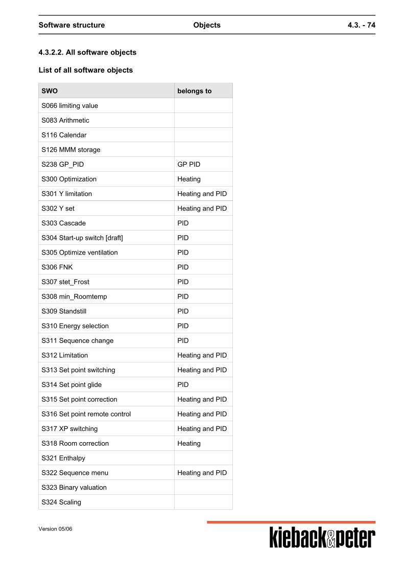
Software structure Objects 4.3. - 74
4.3.2.2. All software objects
List of all software objects
SWO belongs to
S066 limiting value
S083 Arithmetic
S116 Calendar
S126 MMM storage
S238 GP_PID GP PID
S300 Optimization Heating
S301 Y limitation Heating and PID
S302 Y set Heating and PID
S303 Cascade PID
S304 Start-up switch [draft] PID
S305 Optimize ventilation PID
S306 FNK PID
S307 stet_Frost PID
S308 min_Roomtemp PID
S309 Standstill PID
S310 Energy selection PID
S311 Sequence change PID
S312 Limitation Heating and PID
S313 Set point switching Heating and PID
S314 Set point glide PID
S315 Set point correction Heating and PID
S316 Set point remote control Heating and PID
S317 XP switching Heating and PID
S318 Room correction Heating
S321 Enthalpy
S322 Sequence menu Heating and PID
S323 Binary valuation
S324 Scaling
Version 05/06
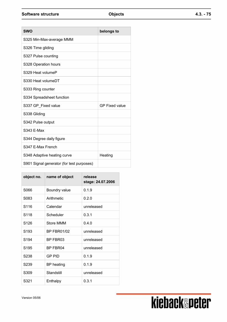
Software structure Objects 4.3. - 75
SWO belongs to
S325 Min-Max-average MMM
S326 Time gliding
S327 Pulse counting
S328 Operation hours
S329 Heat volumeP
S330 Heat volumeDT
S333 Ring counter
S334 Spreadsheet function
S337 GP_Fixed value GP Fixed value
S338 Gliding
S342 Pulse output
S343 E-Max
S344 Degree daily figure
S347 E-Max French
S348 Adaptive heating curve Heating
S901 Signal generator (for test purposes)
object no. name of object releasestage: 24.07.2006
S066 Boundry value 0.1.9
S083 Arithmetic 0.2.0
S116 Calendar unreleased
S118 Scheduler 0.3.1
S126 Store MMM 0.4.0
S193 BP FBR01/02 unreleased
S194 BP FBR03 unreleased
S195 BP FBR04 unreleased
S238 GP PID 0.1.9
S239 BP heating 0.1.9
S309 Standstill unreleased
S321 Enthalpy 0.3.1
Version 05/06
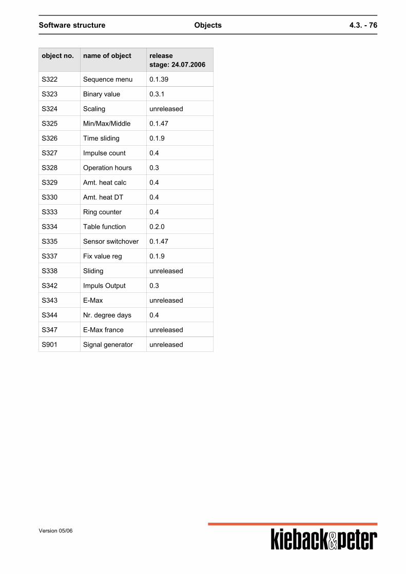
Software structure Objects 4.3. - 76
object no. name of object releasestage: 24.07.2006
S322 Sequence menu 0.1.39
S323 Binary value 0.3.1
S324 Scaling unreleased
S325 Min/Max/Middle 0.1.47
S326 Time sliding 0.1.9
S327 Impulse count 0.4
S328 Operation hours 0.3
S329 Amt. heat calc 0.4
S330 Amt. heat DT 0.4
S333 Ring counter 0.4
S334 Table function 0.2.0
S335 Sensor switchover 0.1.47
S337 Fix value reg 0.1.9
S338 Sliding unreleased
S342 Impuls Output 0.3
S343 E-Max unreleased
S344 Nr. degree days 0.4
S347 E-Max france unreleased
S901 Signal generator unreleased
Version 05/06
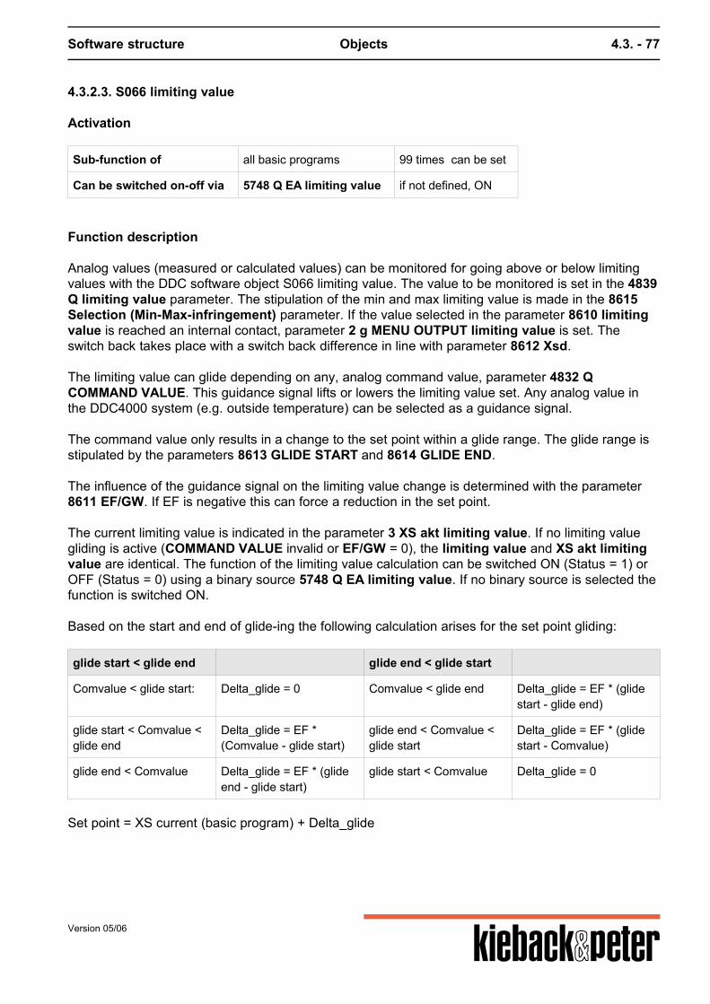
Software structure Objects 4.3. - 77
4.3.2.3. S066 limiting value
Activation
Sub-function of all basic programs 99 times can be set
Can be switched on-off via 5748 Q EA limiting value if not defined, ON
Function description
Analog values (measured or calculated values) can be monitored for going above or below limitingvalues with the DDC software object S066 limiting value. The value to be monitored is set in the 4839Q limiting value parameter. The stipulation of the min and max limiting value is made in the 8615Selection (Min-Max-infringement) parameter. If the value selected in the parameter 8610 limitingvalue is reached an internal contact, parameter 2 g MENU OUTPUT limiting value is set. Theswitch back takes place with a switch back difference in line with parameter 8612 Xsd. The limiting value can glide depending on any, analog command value, parameter 4832 QCOMMAND VALUE. This guidance signal lifts or lowers the limiting value set. Any analog value inthe DDC4000 system (e.g. outside temperature) can be selected as a guidance signal. The command value only results in a change to the set point within a glide range. The glide range isstipulated by the parameters 8613 GLIDE START and 8614 GLIDE END. The influence of the guidance signal on the limiting value change is determined with the parameter8611 EF/GW. If EF is negative this can force a reduction in the set point. The current limiting value is indicated in the parameter 3 XS akt limiting value. If no limiting valuegliding is active (COMMAND VALUE invalid or EF/GW = 0), the limiting value and XS akt limitingvalue are identical. The function of the limiting value calculation can be switched ON (Status = 1) orOFF (Status = 0) using a binary source 5748 Q EA limiting value. If no binary source is selected thefunction is switched ON. Based on the start and end of glide-ing the following calculation arises for the set point gliding:
glide start < glide end glide end < glide start
Comvalue < glide start: Delta_glide = 0 Comvalue < glide end Delta_glide = EF * (glidestart - glide end)
glide start < Comvalue <glide end
Delta_glide = EF *(Comvalue - glide start)
glide end < Comvalue <glide start
Delta_glide = EF * (glidestart - Comvalue)
glide end < Comvalue Delta_glide = EF * (glideend - glide start)
glide start < Comvalue Delta_glide = 0
Set point = XS current (basic program) + Delta_glide
Version 05/06
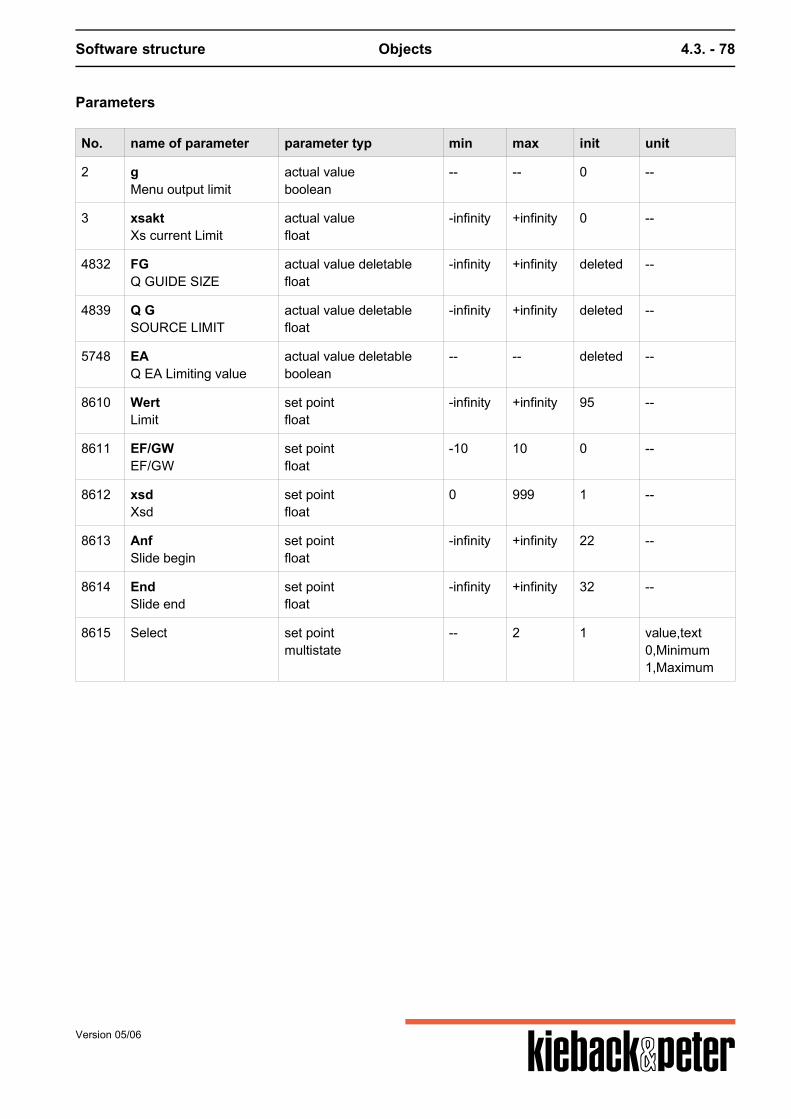
Software structure Objects 4.3. - 78
Parameters
No. name of parameter parameter typ min max init unit
2 gMenu output limit
actual valueboolean
-- -- 0 --
3 xsaktXs current Limit
actual valuefloat
-infinity +infinity 0 --
4832 FGQ GUIDE SIZE
actual value deletablefloat
-infinity +infinity deleted --
4839 Q GSOURCE LIMIT
actual value deletablefloat
-infinity +infinity deleted --
5748 EAQ EA Limiting value
actual value deletableboolean
-- -- deleted --
8610 WertLimit
set pointfloat
-infinity +infinity 95 --
8611 EF/GWEF/GW
set pointfloat
-10 10 0 --
8612 xsdXsd
set pointfloat
0 999 1 --
8613 AnfSlide begin
set pointfloat
-infinity +infinity 22 --
8614 EndSlide end
set pointfloat
-infinity +infinity 32 --
8615 Select set pointmultistate
-- 2 1 value,text0,Minimum1,Maximum
Version 05/06
Software structure Objects 4.3. - 79
4.3.2.4. S083 Arithmetic
Activation
Sub-function of basic heating program and PID 20 times can be set
Can be switched on-off via 2153 Q EA Arithmetic If no binary source is set the calculation isconstant.
Function summary
The DDC software object arithmetic carries out mathematic calculations. Up to 4 analog values or also 4 digital values from the DDC4000 system and any constants can beintegrated into the calculations. The following can be used as mathematic operators:
Basic types of calculation with sample:
+ Addition a+b
- subtraction a-b
* multiplication a*b
/ division a/b
^ Power a^b
mathematical functions:
sqrt square root sqrt(a)
log Logarithm on the basis of e (natural logarithm) ln(a)
log10 Logarithm on the basis of 10 (decimal logarithm) log(a)
exp Exponent on the basis of e exp(c)
sin sine sin(3.141) 1)
asin arc sine asin(1) 2)
sinh Hyberbolic sine sinh(a)
cos Cosine cos(3.141) 1)
acos Arc cosine acos(0) 2)
cosh Hyberbolic cosine cosh(b)
tan tangent tan(3.141/2) 1)
atan Arc tangent atan(1) 2)
Version 05/06
Software structure Objects 4.3. - 80
tanh Hyberbolic tangent tanh(c)
abs absolute number abs(-3)
1) Use with radian2) Result in radian
Logical (Boolean) expressions:
= same
!= not equal
& and
| or
< smaller
<= smaller than or equal
> greater
>= greater than or equal
Exponentials of a figure (based on 10) are implemented with the aid of "e" or "E".e.g.: (1E2) or (1e2) provides the value 100. The expression "exp" is used to calculate the exponents based on e. The calculation of bracketed expressions "(..)" is possible.
The following settings must be included:
- Formula up to 50 characters in length- Operands a, b, c and d (only small letters)- up to 8 different, numerical constants- Constants in decimal depiction (decimal point, leading zero for figures under zero)- up to 7 nested brackets (incl. invisible brackets for organizing the order of calculations)- Spaces are possible (a+b or a + b) Parameter 2152 result depicts the result of the arithmetic calculation. This result can be set as theanalog source for other arithmetic calculations or a true value 0 or 1 (floating value). The result is invalid:- if a source that is not available is set as an operand- for division by zero- if the calculation overruns- if the formula is entered in another wrong way
Version 05/06
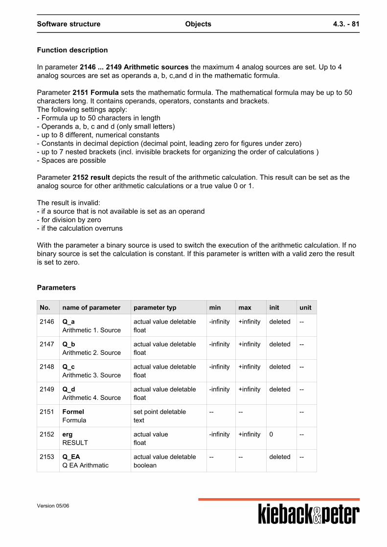
Software structure Objects 4.3. - 81
Function description
In parameter 2146 ... 2149 Arithmetic sources the maximum 4 analog sources are set. Up to 4analog sources are set as operands a, b, c,and d in the mathematic formula. Parameter 2151 Formula sets the mathematic formula. The mathematical formula may be up to 50characters long. It contains operands, operators, constants and brackets.The following settings apply:- Formula up to 50 characters in length- Operands a, b, c and d (only small letters)- up to 8 different, numerical constants- Constants in decimal depiction (decimal point, leading zero for figures under zero)- up to 7 nested brackets (incl. invisible brackets for organizing the order of calculations )- Spaces are possible Parameter 2152 result depicts the result of the arithmetic calculation. This result can be set as theanalog source for other arithmetic calculations or a true value 0 or 1. The result is invalid:- if a source that is not available is set as an operand- for division by zero- if the calculation overruns With the parameter a binary source is used to switch the execution of the arithmetic calculation. If nobinary source is set the calculation is constant. If this parameter is written with a valid zero the resultis set to zero.
Parameters
No. name of parameter parameter typ min max init unit
2146 Q_aArithmetic 1. Source
actual value deletablefloat
-infinity +infinity deleted --
2147 Q_bArithmetic 2. Source
actual value deletablefloat
-infinity +infinity deleted --
2148 Q_cArithmetic 3. Source
actual value deletablefloat
-infinity +infinity deleted --
2149 Q_dArithmetic 4. Source
actual value deletablefloat
-infinity +infinity deleted --
2151 FormelFormula
set point deletabletext
-- -- --
2152 ergRESULT
actual valuefloat
-infinity +infinity 0 --
2153 Q_EAQ EA Arithmatic
actual value deletableboolean
-- -- deleted --
Version 05/06
Software structure Objects 4.3. - 82
4.3.2.5. S126 MMM storage
Activation
Sub-function of - 20 times can be set
Function summary
The DDC software object S126 MMM storage supplies the maximum value, minimum value andaverage of an analogue source. In addition the values determined by the analogue source can besaved for a particular point of time.
2165 source MMMplannable source on any analogue value of the DDC4000 system. If the source is invalid or deleted the current min, max and average values are frozen. When thesource is valid again the current min, max and average values are reset to the current source value.The saved values are not affected by this. 2166 Max act.Maximum value determined since the time of the last reset. 2167 Min act.Minimum value determined since the time of the last reset. 2168 Average act.Average value calculated since the time of the last reset. 2195 Q storageplannable source on any binary value of the DDC4000 system. With the change from "0" to "1" themin, max and average values are reset and saved.For example the values can be saved for a defined period of time through the use of a time programoutput. Through the use of a timer the saving can be released at regular intervals. 2196 Max stor.Maximum value at the reset time. 2197 Min stor.Minimum value at the reset time. 2198 Average stor.Average value at the reset time. 2199 Input stor.Current value of the 2165 source MMM at the reset time.
Version 05/06
Software structure Objects 4.3. - 83
Parameters
No. name of parameter parameter typ min max init unit
2165 Q_InputStore Source MMM
actual value deletablefloat
-infinity +infinity deleted --
2166 MaxMax Value / t
actual valuefloat
-infinity +infinity 0 --
2167 MinMin Value / t
actual valuefloat
-infinity +infinity 0 --
2168 MittelAverage Value / t
actual valuefloat
-infinity +infinity 0 --
2169 DATE actual valueinteger
0 0 0 --
2195 Q_SpStore Q
actual value deletableboolean
-- -- deleted --
2196 Max_sStored Max Value
actual valuefloat
-infinity +infinity 0 --
2197 Min_sStored Min Value
actual valuefloat
-infinity +infinity 0 --
2198 Mittel_sStored Average Value
actual valuefloat
-infinity +infinity 0 --
2199 Input_sStored Input
actual valuefloat
-infinity +infinity 0 --
2200 TIME actual valueinteger
0 24 0 h
Version 05/06
Software structure Objects 4.3. - 84
4.3.2.9. S238 Basic program PID (ventilation)
Activation
Basic program PID (ventilation) can be set 12 x
Function summary
This basic program is a PID control with 4 sequences. Using binary source parameters integrationinto the ventilation controls and regulations is possible without any problems.Function extensions are made via DDC soft- and hardware objects.
Function description
The control variable sensor must be defined in parameter 5102 source control variable. AnyDDC4000 system analog value can be set. As an outside sensor, any analog value in the DDC system can also be set in parameter 5103source TO. This parameter is used in combination with other DDC sub-software objects , e.g.S307constant frost protection. If not required, no setting is required. In parameter 5100 XS the desired set point for the fixed value regulation is set. On the basis of thisset point and the function of other DDC sub-software objects (e.g. S314 set point gliding, S313 setpoint switching) a new set point is calculated that is depicted as the current value on parameter5101 XS current. In the basic PID program up to 4 constant Y outputs are available. The calculation of the Y outputs ismade if the control circuit is in "Control ON" operation mode. Otherwise the Y outputs are in thestatus assigned to them for the uncontrolled status by parameter 5127 uncontrolled condition. (0 =0 %, 1 = 100 %) The values of the Y outputs calculated by the basic program can be overwritten by manualintervention (7801 manual intervention .. 7804 manual intervention Y04), BMS intervention (h01 ..h04) or by DDC sub-software objects (e.g. S302 Y set). The current values of the Y outputs are displayed in the parameters 5110 YL1... 5113 YL4. For each Y output a max and min limit parameter 5141 .. 5148 can be set (e. g. for stipulating aminimum outside air rate MAR). In parameter 5126 Sequence various sequences can be set for the individual Y outputs. The output of the Y output values occurs via source parameterizing in the basic programs of the DDCCentral Units (DDC4000) and the DDC modules (DDC bus module BMA, field bus module FBM,control cabinet bus module SBM). The parameters 5130 .. 5132 Xdz.. can stipulate idle zones between the individual Y outputsequences. The situation of the relevant set point can be seen from the figure.
Version 05/06
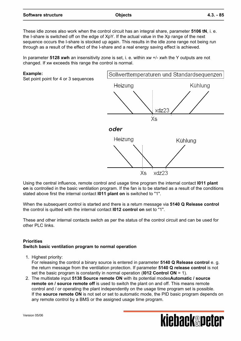
Software structure Objects 4.3. - 85
These idle zones also work when the control circuit has an integral share, parameter 5106 tN, i. e.the I-share is switched off on the edge of XpY. If the actual value in the Xp range of the nextsequence occurs the I-share is stocked up again. This results in the idle zone range not being runthrough as a result of the effect of the I-share and a real energy saving effect is achieved. In parameter 5128 xwh an insensitivity zone is set, i. e. within xw +/- xwh the Y outputs are notchanged. If xw exceeds this range the control is normal.
Example:Set point point for 4 or 3 sequences
Using the central influence, remote control and usage time program the internal contact I011 planton is controlled in the basic ventilation program. If the fan is to be started as a result of the conditionsstated above first the internal contact I011 plant on is switched to "1". When the subsequent control is started and there is a return message via 5140 Q Release controlthe control is quitted with the internal contact I012 control on set to "1". These and other internal contacts switch as per the status of the control circuit and can be used forother PLC links.
PrioritiesSwitch basic ventilation program to normal operation
1. Highest priority:For releasing the control a binary source is entered in parameter 5140 Q Release control e. g.the return message from the ventilation protection. If parameter 5140 Q release control is notset the basic program is constantly in normal operation (I012 Control ON = 1).
2. The multistate input 5138 Source remote ON with its potential modesAutomatic / sourceremote on / source remote off is used to switch the plant on and off. This means remotecontrol and / or operating the plant independently on the usage time program set is possible.If the source remote ON is not set or set to automatic mode, the PID basic program depends onany remote control by a BMS or the assigned usage time program.
Version 05/06
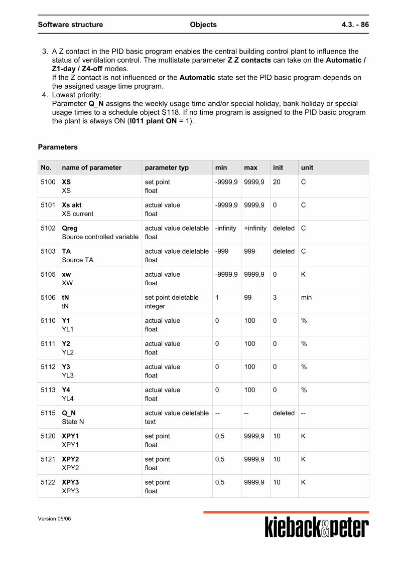
Software structure Objects 4.3. - 86
3. A Z contact in the PID basic program enables the central building control plant to influence thestatus of ventilation control. The multistate parameter Z Z contacts can take on the Automatic /Z1-day / Z4-off modes.If the Z contact is not influenced or the Automatic state set the PID basic program depends onthe assigned usage time program.
4. Lowest priority:Parameter Q_N assigns the weekly usage time and/or special holiday, bank holiday or specialusage times to a schedule object S118. If no time program is assigned to the PID basic programthe plant is always ON (I011 plant ON = 1).
Parameters
No. name of parameter parameter typ min max init unit
5100 XSXS
set pointfloat
-9999,9 9999,9 20 C
5101 Xs aktXS current
actual valuefloat
-9999,9 9999,9 0 C
5102 QregSource controlled variable
actual value deletablefloat
-infinity +infinity deleted C
5103 TASource TA
actual value deletablefloat
-999 999 deleted C
5105 xwXW
actual valuefloat
-9999,9 9999,9 0 K
5106 tNtN
set point deletableinteger
1 99 3 min
5110 Y1YL1
actual valuefloat
0 100 0 %
5111 Y2YL2
actual valuefloat
0 100 0 %
5112 Y3YL3
actual valuefloat
0 100 0 %
5113 Y4YL4
actual valuefloat
0 100 0 %
5115 Q_NState N
actual value deletabletext
-- -- deleted --
5120 XPY1XPY1
set pointfloat
0,5 9999,9 10 K
5121 XPY2XPY2
set pointfloat
0,5 9999,9 10 K
5122 XPY3XPY3
set pointfloat
0,5 9999,9 10 K
Version 05/06
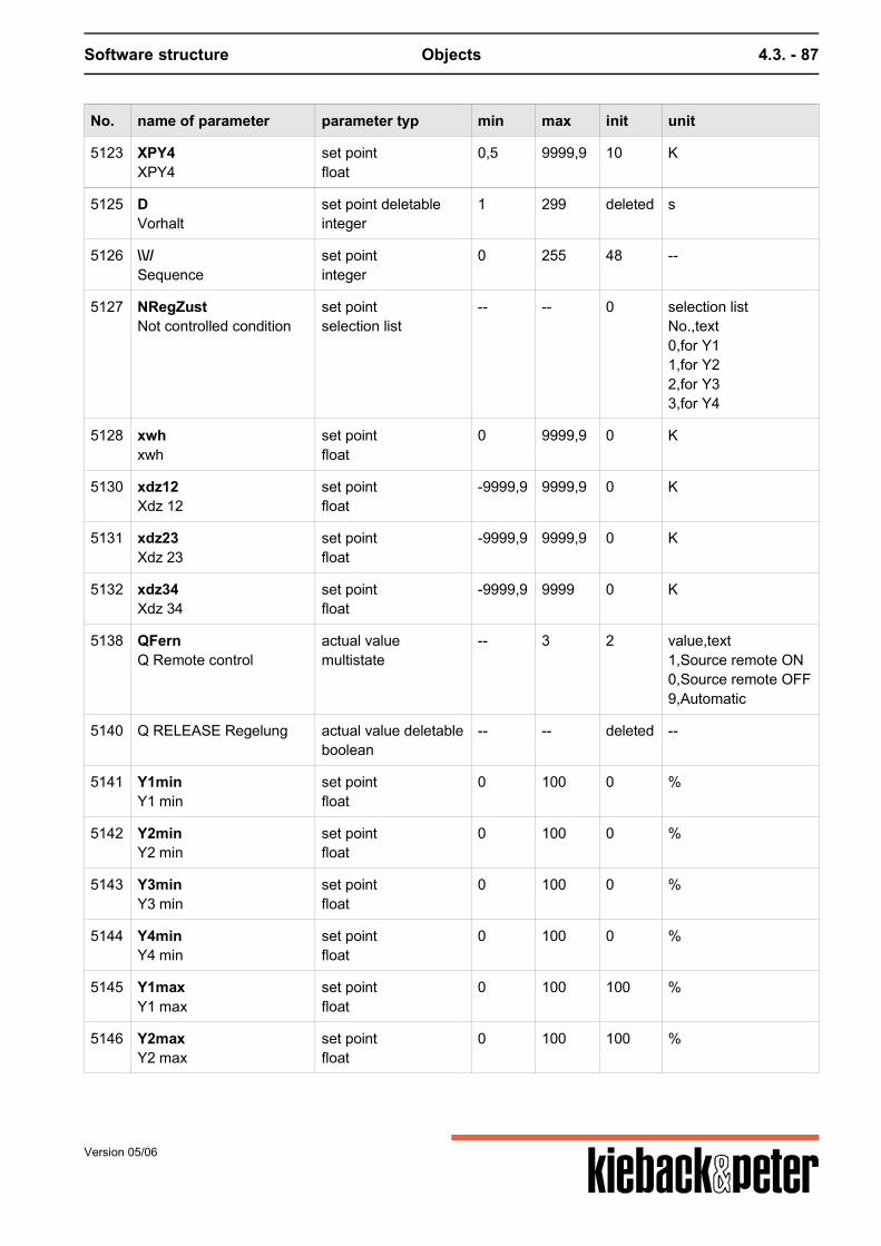
Software structure Objects 4.3. - 87
No. name of parameter parameter typ min max init unit
5123 XPY4XPY4
set pointfloat
0,5 9999,9 10 K
5125 DVorhalt
set point deletableinteger
1 299 deleted s
5126 \\//Sequence
set pointinteger
0 255 48 --
5127 NRegZustNot controlled condition
set pointselection list
-- -- 0 selection listNo.,text0,for Y11,for Y22,for Y33,for Y4
5128 xwhxwh
set pointfloat
0 9999,9 0 K
5130 xdz12Xdz 12
set pointfloat
-9999,9 9999,9 0 K
5131 xdz23Xdz 23
set pointfloat
-9999,9 9999,9 0 K
5132 xdz34Xdz 34
set pointfloat
-9999,9 9999 0 K
5138 QFernQ Remote control
actual valuemultistate
-- 3 2 value,text1,Source remote ON0,Source remote OFF9,Automatic
5140 Q RELEASE Regelung actual value deletableboolean
-- -- deleted --
5141 Y1minY1 min
set pointfloat
0 100 0 %
5142 Y2minY2 min
set pointfloat
0 100 0 %
5143 Y3minY3 min
set pointfloat
0 100 0 %
5144 Y4minY4 min
set pointfloat
0 100 0 %
5145 Y1maxY1 max
set pointfloat
0 100 100 %
5146 Y2maxY2 max
set pointfloat
0 100 100 %
Version 05/06
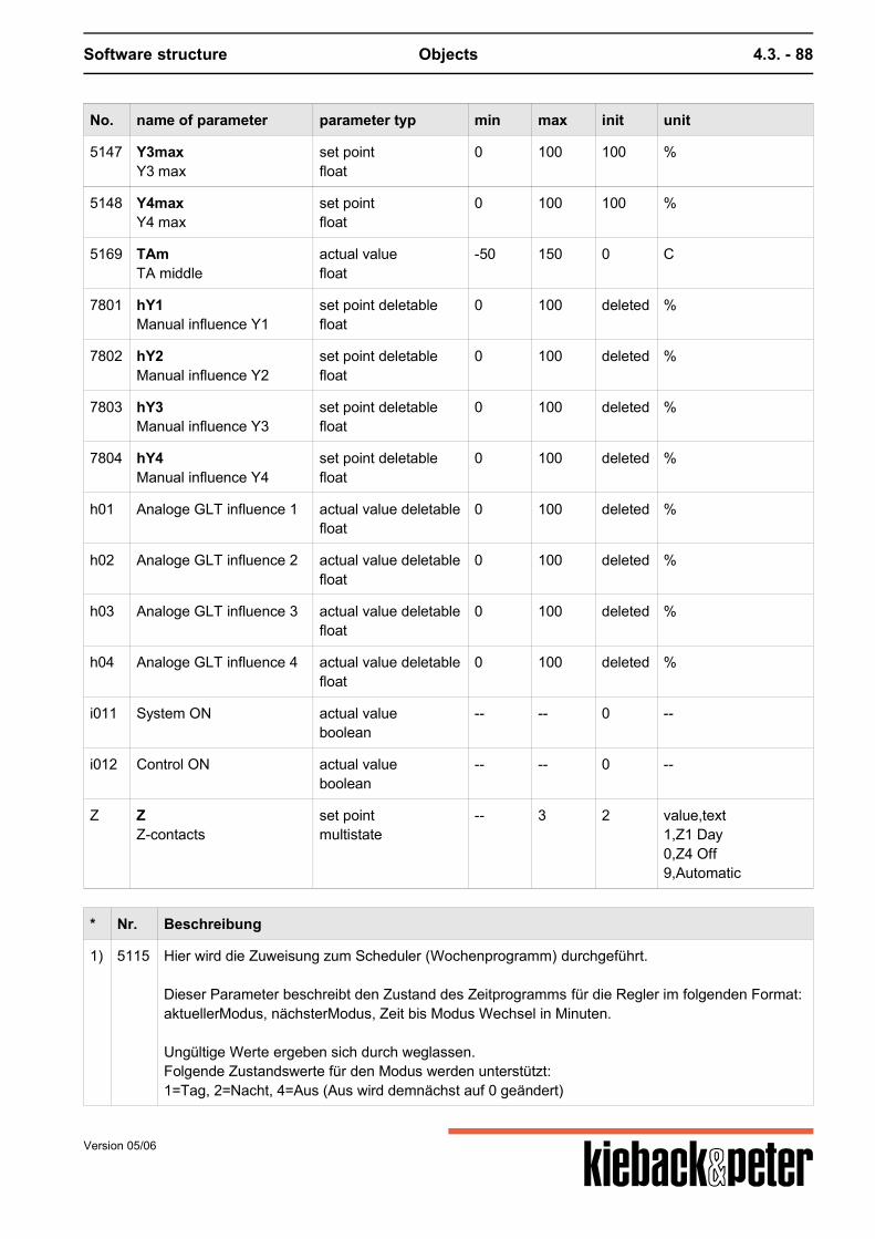
Software structure Objects 4.3. - 88
No. name of parameter parameter typ min max init unit
5147 Y3maxY3 max
set pointfloat
0 100 100 %
5148 Y4maxY4 max
set pointfloat
0 100 100 %
5169 TAmTA middle
actual valuefloat
-50 150 0 C
7801 hY1Manual influence Y1
set point deletablefloat
0 100 deleted %
7802 hY2Manual influence Y2
set point deletablefloat
0 100 deleted %
7803 hY3Manual influence Y3
set point deletablefloat
0 100 deleted %
7804 hY4Manual influence Y4
set point deletablefloat
0 100 deleted %
h01 Analoge GLT influence 1 actual value deletablefloat
0 100 deleted %
h02 Analoge GLT influence 2 actual value deletablefloat
0 100 deleted %
h03 Analoge GLT influence 3 actual value deletablefloat
0 100 deleted %
h04 Analoge GLT influence 4 actual value deletablefloat
0 100 deleted %
i011 System ON actual valueboolean
-- -- 0 --
i012 Control ON actual valueboolean
-- -- 0 --
Z ZZ-contacts
set pointmultistate
-- 3 2 value,text1,Z1 Day0,Z4 Off9,Automatic
* Nr. Beschreibung
1) 5115 Hier wird die Zuweisung zum Scheduler (Wochenprogramm) durchgeführt. Dieser Parameter beschreibt den Zustand des Zeitprogramms für die Regler im folgenden Format:aktuellerModus, nächsterModus, Zeit bis Modus Wechsel in Minuten. Ungültige Werte ergeben sich durch weglassen.Folgende Zustandswerte für den Modus werden unterstützt:1=Tag, 2=Nacht, 4=Aus (Aus wird demnächst auf 0 geändert)
Version 05/06

Software structure Objects 4.3. - 89
DDC sub-software objects
Version 05/06
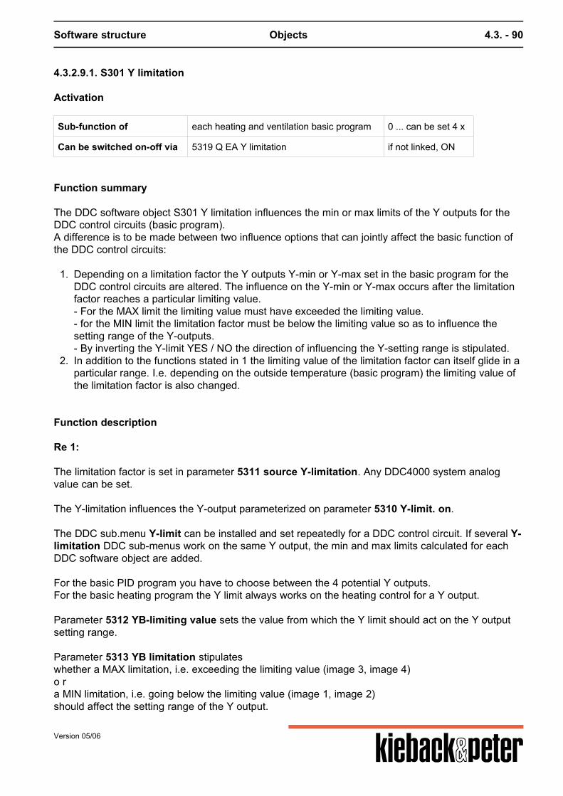
Software structure Objects 4.3. - 90
4.3.2.9.1. S301 Y limitation
Activation
Sub-function of each heating and ventilation basic program 0 ... can be set 4 x
Can be switched on-off via 5319 Q EA Y limitation if not linked, ON
Function summary
The DDC software object S301 Y limitation influences the min or max limits of the Y outputs for theDDC control circuits (basic program).A difference is to be made between two influence options that can jointly affect the basic function ofthe DDC control circuits:
1. Depending on a limitation factor the Y outputs Y-min or Y-max set in the basic program for theDDC control circuits are altered. The influence on the Y-min or Y-max occurs after the limitationfactor reaches a particular limiting value.- For the MAX limit the limiting value must have exceeded the limiting value.- for the MIN limit the limitation factor must be below the limiting value so as to influence thesetting range of the Y-outputs.- By inverting the Y-limit YES / NO the direction of influencing the Y-setting range is stipulated.
2. In addition to the functions stated in 1 the limiting value of the limitation factor can itself glide in aparticular range. I.e. depending on the outside temperature (basic program) the limiting value ofthe limitation factor is also changed.
Function description
Re 1: The limitation factor is set in parameter 5311 source Y-limitation. Any DDC4000 system analogvalue can be set. The Y-limitation influences the Y-output parameterized on parameter 5310 Y-limit. on.
The DDC sub.menu Y-limit can be installed and set repeatedly for a DDC control circuit. If several Y-limitation DDC sub-menus work on the same Y output, the min and max limits calculated for eachDDC software object are added.
For the basic PID program you have to choose between the 4 potential Y outputs.For the basic heating program the Y limit always works on the heating control for a Y output. Parameter 5312 YB-limiting value sets the value from which the Y limit should act on the Y outputsetting range. Parameter 5313 YB limitation stipulateswhether a MAX limitation, i.e. exceeding the limiting value (image 3, image 4)o ra MIN limitation, i.e. going below the limiting value (image 1, image 2)should affect the setting range of the Y output.
Version 05/06
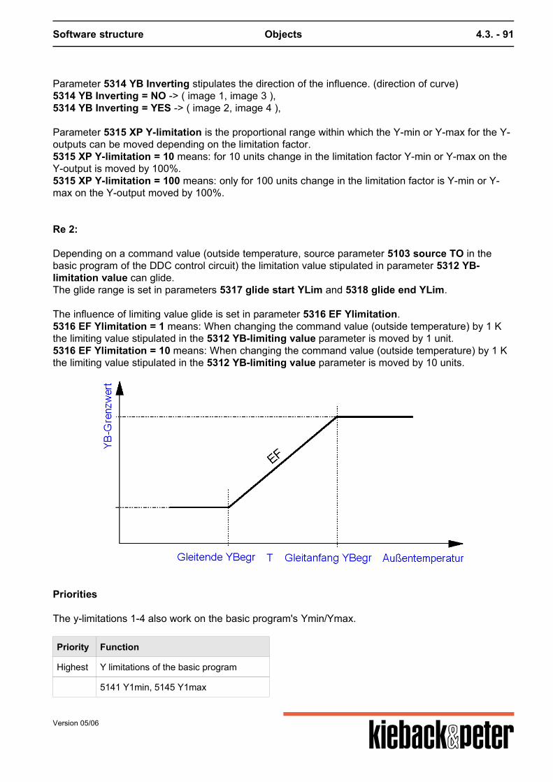
Software structure Objects 4.3. - 91
Parameter 5314 YB Inverting stipulates the direction of the influence. (direction of curve)5314 YB Inverting = NO -> ( image 1, image 3 ),5314 YB Inverting = YES -> ( image 2, image 4 ), Parameter 5315 XP Y-limitation is the proportional range within which the Y-min or Y-max for the Y-outputs can be moved depending on the limitation factor.5315 XP Y-limitation = 10 means: for 10 units change in the limitation factor Y-min or Y-max on theY-output is moved by 100%.5315 XP Y-limitation = 100 means: only for 100 units change in the limitation factor is Y-min or Y-max on the Y-output moved by 100%. Re 2: Depending on a command value (outside temperature, source parameter 5103 source TO in thebasic program of the DDC control circuit) the limitation value stipulated in parameter 5312 YB-limitation value can glide.The glide range is set in parameters 5317 glide start YLim and 5318 glide end YLim. The influence of limiting value glide is set in parameter 5316 EF Ylimitation.5316 EF Ylimitation = 1 means: When changing the command value (outside temperature) by 1 Kthe limiting value stipulated in the 5312 YB-limiting value parameter is moved by 1 unit.5316 EF Ylimitation = 10 means: When changing the command value (outside temperature) by 1 Kthe limiting value stipulated in the 5312 YB-limiting value parameter is moved by 10 units.
Priorities
The y-limitations 1-4 also work on the basic program's Ymin/Ymax.
Priority Function
Highest Y limitations of the basic program
5141 Y1min, 5145 Y1max
Version 05/06
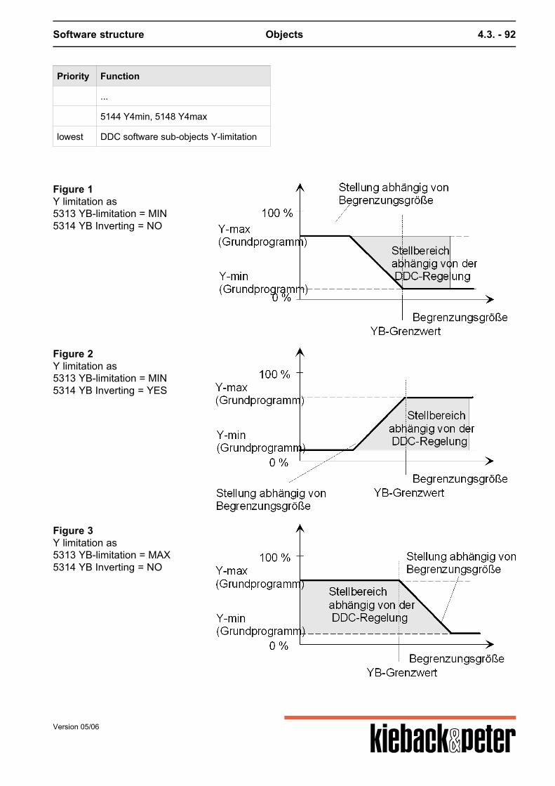
Software structure Objects 4.3. - 92
Priority Function
...
5144 Y4min, 5148 Y4max
lowest DDC software sub-objects Y-limitation
Figure 1Y limitation as5313 YB-limitation = MIN5314 YB Inverting = NO
Figure 2Y limitation as5313 YB-limitation = MIN5314 YB Inverting = YES
Figure 3Y limitation as5313 YB-limitation = MAX5314 YB Inverting = NO
Version 05/06
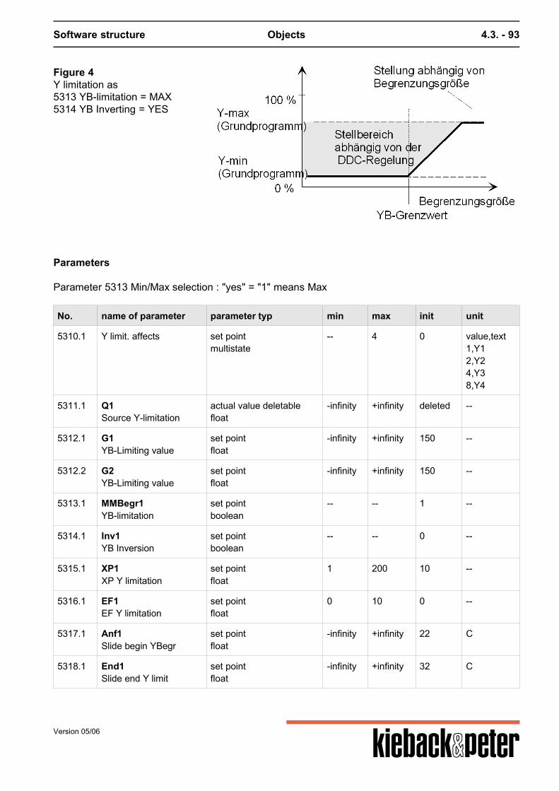
Software structure Objects 4.3. - 93
Figure 4Y limitation as5313 YB-limitation = MAX5314 YB Inverting = YES
Parameters
Parameter 5313 Min/Max selection : "yes" = "1" means Max
No. name of parameter parameter typ min max init unit
5310.1 Y limit. affects set pointmultistate
-- 4 0 value,text1,Y12,Y24,Y38,Y4
5311.1 Q1Source Y-limitation
actual value deletablefloat
-infinity +infinity deleted --
5312.1 G1YB-Limiting value
set pointfloat
-infinity +infinity 150 --
5312.2 G2YB-Limiting value
set pointfloat
-infinity +infinity 150 --
5313.1 MMBegr1YB-limitation
set pointboolean
-- -- 1 --
5314.1 Inv1YB Inversion
set pointboolean
-- -- 0 --
5315.1 XP1XP Y limitation
set pointfloat
1 200 10 --
5316.1 EF1EF Y limitation
set pointfloat
0 10 0 --
5317.1 Anf1Slide begin YBegr
set pointfloat
-infinity +infinity 22 C
5318.1 End1Slide end Y limit
set pointfloat
-infinity +infinity 32 C
Version 05/06

Software structure Objects 4.3. - 94
No. name of parameter parameter typ min max init unit
5319.1 EA1Q EA Y-limitation
actual value deletableboolean
-- -- deleted --
5320.1 YBegrY-Limiting 1 active
actual valueboolean
-- -- 0 --
No. name of parameter parameter typ min max init unit
5310.2 Y limit. affects set pointmultistate
-- 4 0 value,text1,Y12,Y24,Y38,Y4
5311.2 Q2Source Y-limitation
actual value deletablefloat
-infinity +infinity deleted --
5312.2 G2YB-Limiting value
set pointfloat
-infinity +infinity 150 --
5313.2 MMBegr2YB-limitation
set pointboolean
-- -- 1 --
5314.2 Inv2YB Inversion
set pointboolean
-- -- 0 --
5315.2 XP2XP Y limitation
set pointfloat
1 200 10 --
5316.2 EF2EF Y limitation
set pointfloat
0 10 0 --
5317.2 Anf2Slide begin YBegr
set pointfloat
-infinity +infinity 22 C
5318.2 End2Slide end Y limit
set pointfloat
-infinity +infinity 32 C
5319.2 EA2Q EA Y-limitation
actual value deletableboolean
-- -- deleted --
5320.2 YBegrY-Limiting 2 active
actual valueboolean
-- -- 0 --
No. name of parameter parameter typ min max init unit
5310.3 Y limit. affects set pointmultistate
-- 4 0 value,text1,Y12,Y24,Y38,Y4
Version 05/06
Software structure Objects 4.3. - 95
No. name of parameter parameter typ min max init unit
5311.3 Q3Source Y-limitation
actual value deletablefloat
-infinity +infinity deleted --
5312.3 G3YB-Limiting value
set pointfloat
-infinity +infinity 150 --
5313.3 MMBegr3YB-limitation
set pointboolean
-- -- 1 --
5314.3 Inv3YB Inversion
set pointboolean
-- -- 0 --
5315.3 XP3XP Y limitation
set pointfloat
1 200 10 --
5316.3 EF3EF Y limitation
set pointfloat
0 10 0 --
5317.3 Anf3Slide begin YBegr
set pointfloat
-infinity +infinity 22 C
5318.3 End3Slide end Y limit
set pointfloat
-infinity +infinity 32 C
5319.3 EA3Q EA Y-limitation
actual value deletableboolean
-- -- deleted --
5320.3 YBegrY-Limiting 3 active
actual valueboolean
-- -- 0 --
No. name of parameter parameter typ min max init unit
5310.4 Y limit. affects set pointmultistate
-- 4 0 value,text1,Y12,Y24,Y38,Y4
5311.4 Q4Source Y-limitation
actual value deletablefloat
-infinity +infinity deleted --
5312.4 G4YB-Limiting value
set pointfloat
-infinity +infinity 150 --
5313.4 MMBegr4YB-limitation
set pointboolean
-- -- 1 --
5314.4 Inv4YB Inversion
set pointboolean
-- -- 0 --
5315.4 XP4XP Y limitation
set pointfloat
1 200 10 --
5316.4 EF4EF Y limitation
set pointfloat
0 10 0 --
Version 05/06

Software structure Objects 4.3. - 96
No. name of parameter parameter typ min max init unit
5317.4 Anf4Slide begin YBegr
set pointfloat
-infinity +infinity 22 C
5318.4 End4Slide end Y limit
set pointfloat
-infinity +infinity 32 C
5319.4 EA4Q EA Y-limitation
actual value deletableboolean
-- -- deleted --
5320.4 YBegrY-Limiting 4 active
actual valueboolean
-- -- 0 --
Version 05/06
Software structure Objects 4.3. - 97
4.3.2.9.2. S302 Y set
Activation
Sub-function of basic heating and ventilation program 0 ... can be set 4 x
Can be switched on-off via 5327 Q Y-SET if not defined, ON
Function summary
With the Y-set DDC submenu the Y outputs of the DDC control circuits are stipulated by binarysignals on certain (parameterizable) Y-values. If the binary signal = 1 the stipulated Y value works onthe Y output.
Function description
The Y-set DDC software object can be installed and set up to four times for one DDC control circuit.For this Y-set can work repeatedly on the same Y-output. The address of the binary source is entered in parameter 5327 Q Y-SET. If the binary source ="1",the analog value set in parameter 5326 Y-SET value (0 ..100 %) is transferred to the Y-output.Parameter 5325 destination Y-SET sets the Y output that is to be influenced.For the basic PID program you have to choose between the 4 potential Y outputs. For the basicheating program the Y-set always works on the heating control for a Y output. Priorities
Priority Function
Highest Manual intervention
Central influence
Y set (Index 01)
Y set (Index 04)
Limitation functions
lowest Basic program control function
Version 05/06
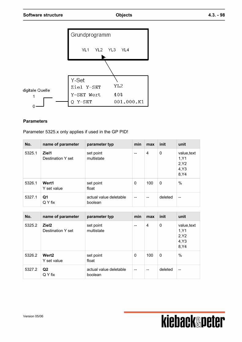
Software structure Objects 4.3. - 98
Parameters
Parameter 5325.x only applies if used in the GP PID!
No. name of parameter parameter typ min max init unit
5325.1 Ziel1Destination Y set
set pointmultistate
-- 4 0 value,text1,Y12,Y24,Y38,Y4
5326.1 Wert1Y set value
set pointfloat
0 100 0 %
5327.1 Q1Q Y fix
actual value deletableboolean
-- -- deleted --
No. name of parameter parameter typ min max init unit
5325.2 Ziel2Destination Y set
set pointmultistate
-- 4 0 value,text1,Y12,Y24,Y38,Y4
5326.2 Wert2Y set value
set pointfloat
0 100 0 %
5327.2 Q2Q Y fix
actual value deletableboolean
-- -- deleted --
Version 05/06

Software structure Objects 4.3. - 99
No. name of parameter parameter typ min max init unit
5325.3 Ziel3Destination Y set
set pointmultistate
-- 4 0 value,text1,Y12,Y24,Y38,Y4
5326.3 Wert3Y set value
set pointfloat
0 100 0 %
5327.3 Q3Q Y fix
actual value deletableboolean
-- -- deleted --
No. name of parameter parameter typ min max init unit
5325.4 Ziel4Destination Y set
set pointmultistate
-- 4 0 value,text1,Y12,Y24,Y38,Y4
5326.4 Wert4Y set value
set pointfloat
0 100 0 %
5327.4 Q4Q Y fix
actual value deletableboolean
-- -- deleted --
Version 05/06
Software structure Objects 4.3. - 100
4.3.2.9.3. S303 Cascade
Activation
Sub-function of Basic PID program can be set 1 x
Can be switched on-off via 5210 Source EA cascade if not defined, ON
When switching between ON/OFF and OFF/ON a gliding transfer takes place in the control unit!
Function description
In the DDC sub-menu S303 Cascade the exhaust air temperature sensor is set in parameter 5200Cascade sensor. The supply air temperature is in parameter 5102 Source control variable fromthe PID basic program. Example:Main control variable: exhaust air in DDC cascade sub-menuAuxiliary control variable: supply air in the basic program If the exhaust air temperature (main control variable) varies from the current set point 5101 XSactualthe supply air temperature (auxiliary control variable) is raised or lowered. The supply air set point5205 XS supply air Casc. counteracts the offset in the room and ensures fast, stable control. The exhaust air control circuit works in the normal setting with a P control behavior. The influence ofthe offset room/exhaust air on the supply air change is set with parameter 5201 ER (Xs supply air =XS current + ER * xw room/exhaust air). If the room or exhaust air temperature works as a PI controlfunction on the supply air control circuit the reset time for the exhaust air control circuit is entered inparameter 5202 tN cascade. Depending on the setting in 5202 tN cascade the following control behaviour can be set:P/P- , PI/PI- , P/PI- , PI/P behavior For the supply air temperature it is possible to set both a minimum and a maximum limit (parameter5203 supply air min limit, 5204 supply air max limit.) If the supply air temperature is lower than 5203 supply air min limit or exceeds 5204 supply airmax limit, the internal output I021 Limit cascade is set to "1". If a valid value is entered in parameter5273 XP limit for all basic program XPYs are switched to XP Limit cascade and the I20 (XPswitching) is also activated. If the max. limiting value is below the min limiting value the max. limiting value is invalid. Parameter 5208 Maxdiff sets a limit for the temperature difference between the supply airtemperature and room temperature. The precondition for limiting the temperature difference isplacing the control variable sensor in the room. This limit function prevents temperature layers inhigh, cold rooms or halls. For an unlimited increase in temperature difference between supply air androom the cooler, heavier air in the lower part of the room would act as an air cushion that is notpenetrated by the warmer, lighter supply air from the ceiling. Parameter 5208 Maxdiff can also be set to negative. In this case the supply air on 5208 Maxdiff is
Version 05/06
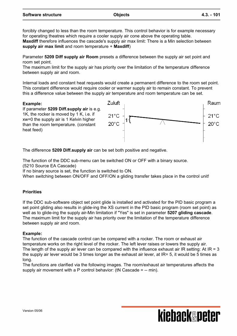
Software structure Objects 4.3. - 101
forcibly changed to less than the room temperature. This control behavior is for example necessaryfor operating theatres which require a cooler supply air cone above the operating table.Maxdiff therefore influences the cascade's supply air max limit: There is a Min selection betweensupply air max limit and room temperature + Maxdiff) Parameter 5209 Diff supply air Room presets a difference between the supply air set point androom set point.The maximum limit for the supply air has priority over the limitation of the temperature differencebetween supply air and room. Internal loads and constant heat requests would create a permanent difference to the room set point.This constant difference would require cooler or warmer supply air to remain constant. To preventthis a difference value between the supply air temperature and room temperature can be set.
Example:If parameter 5209 Diff.supply air is e.g.1K, the rocker is moved by 1 K, i.e. ifxw=0 the supply air is 1 Kelvin higherthan the room temperature. (constantheat feed)
The difference 5209 Diff.supply air can be set both positive and negative. The function of the DDC sub-menu can be switched ON or OFF with a binary source.(5210 Source EA Cascade)If no binary source is set, the function is switched to ON.When switching between ON/OFF and OFF/ON a gliding transfer takes place in the control unit!
Priorities
If the DDC sub-software object set point glide is installed and activated for the PID basic program aset point gliding also results in glide-ing the XS current in the PID basic program (room set point) aswell as to glide-ing the supply air-Min limitation if "Yes" is set in parameter 5207 gliding cascade.The maximum limit for the supply air has priority over the limitation of the temperature differencebetween supply air and room.
Example:The function of the cascade control can be compared with a rocker. The room or exhaust airtemperature works on the right level of the rocker. The left lever raises or lowers the supply air.The length of the supply air lever can be compared with the influence exhaust air IR setting: At IR = 3the supply air lever would be 3 times longer as the exhaust air lever, at IR= 5, it would be 5 times aslong.The functions are clarified via the following images. The room/exhaust air temperatures affects thesupply air movement with a P control behavior: (tN Cascade = -- min).
Version 05/06
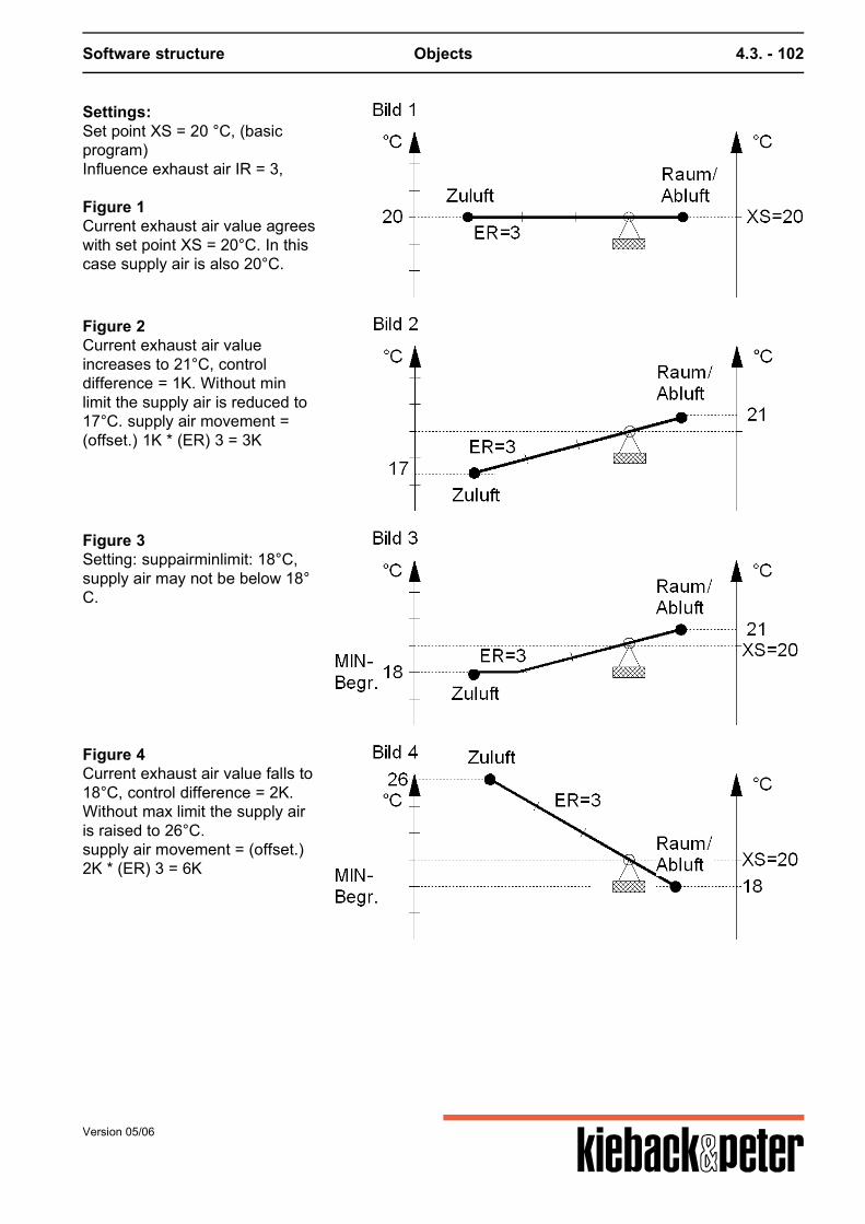
Software structure Objects 4.3. - 102
Settings:Set point XS = 20 °C, (basicprogram)Influence exhaust air IR = 3, Figure 1Current exhaust air value agreeswith set point XS = 20°C. In thiscase supply air is also 20°C.
Figure 2Current exhaust air valueincreases to 21°C, controldifference = 1K. Without minlimit the supply air is reduced to17°C. supply air movement =(offset.) 1K * (ER) 3 = 3K
Figure 3Setting: suppairminlimit: 18°C,supply air may not be below 18°C.
Figure 4Current exhaust air value falls to18°C, control difference = 2K.Without max limit the supply airis raised to 26°C.supply air movement = (offset.)2K * (ER) 3 = 6K
Version 05/06
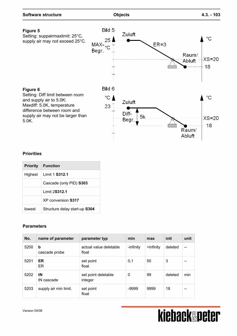
Software structure Objects 4.3. - 103
Figure 5Setting: suppairmaxlimit: 25°C,supply air may not exceed 25°C.
Figure 6Setting: Diff limit between roomand supply air to 5.0K:Maxdiff: 5.0K, temperaturedifference between room andsupply air may not be larger than5.0K.
Priorities
Priority Function
Highest Limit 1 S312.1
Cascade (only PID) S303
Limit 2S312.1
XP conversion S317
lowest Structure delay start-up S304
Parameters
No. name of parameter parameter typ min max init unit
5200 bcascade probe
actual value deletablefloat
-infinity +infinity deleted --
5201 ERER
set pointfloat
0,1 50 3 --
5202 tNtN cascade
set point deletableinteger
0 99 deleted min
5203 supply air min limit. set pointfloat
-9999 9999 18 --
Version 05/06
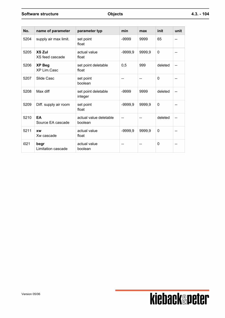
Software structure Objects 4.3. - 104
No. name of parameter parameter typ min max init unit
5204 supply air max limit. set pointfloat
-9999 9999 65 --
5205 XS ZulXS feed cascade
actual valuefloat
-9999,9 9999,9 0 --
5206 XP BegXP Lim.Casc
set point deletablefloat
0,5 999 deleted --
5207 Slide Casc set pointboolean
-- -- 0 --
5208 Max diff set point deletableinteger
-9999 9999 deleted --
5209 Diff. supply air room set pointfloat
-9999,9 9999,9 0 --
5210 EASource EA cascade
actual value deletableboolean
-- -- deleted --
5211 xwXw cascade
actual valuefloat
-9999,9 9999,9 0 --
i021 begrLimitation cascade
actual valueboolean
-- -- 0 --
Version 05/06
Software structure Objects 4.3. - 105
4.3.2.9.4. S304 start up switching
Activation
Sub-function of basic ventilation program 0 ... can be set once
Can be switched on-off via 5438 Q EA start-up if not defined, ON
Function summary
The movement switch only switches the ventilation plant on when the heating register is heated.
Function description
The movement switch is released (I022 Movement = 1) when the external temperature falls belowthe value parameterized in 5332 TOgrenz AF and the control = NIGHT is in automatic operation via atiming program or the control = OFF due to forced control (Remote OFF or Z-contact OFF).(The lower external temperature is just one criterion for movement switching! If the externaltemperature goes up during an active movement phase this does not abort!)If the ventilation plant is operational, e.g. as a result of usage times or remote switching the selectedheating valve opens first 5331 Target movement Y. After the entered opening time 5335 Openingtime has ended the heating valve is 100% open. The length of the total cleaning time depends onwhether a return temperature sensor was connected. a) There is no return temperature sensor available:At the same time as the opening the release delay is also active 5336 Release delay. After it endsthe internal contact I011 Plant ON = 1 is switched on. b) There is a return temperature sensor 5333 Return sensor available:The heating valve is opened until the return temperature sensor the limiting value 5334 LimitT Return AF is exceeded. Then the internal contactI011 Plant ON =1 is switched on.
The heating valve remains in the last position until the internal contact I012 Control ON switches onthe PID control.If the control is not switched on via I012 Control ON the movement process is aborted. The heatingvalve closes again. However the movement switch remains active (I022 Movement = 1). After the internal contact I012 control ON = 1 has been switched on the transfer from advanceopening of the heating valve /reaching the return temperature to regular operation occurs withoutimpacts. The impact-free switching occurs with the aid of a period stated in 5337 Structure delay. Inthis period the PID controller is operated as the P-controller with a normal variance limited tomaximum 1 K and double proportional range.[XWStructure delay = MAX(XWGP, 1 K), XPStructure delay all Y = 2 * XPGP Movement Y] The "movement" status, i.e. the ventilation plant should become operational and the movementswitching works, is indicated throughout the whole time by internal contact I022 Movement = 1.
Version 05/06
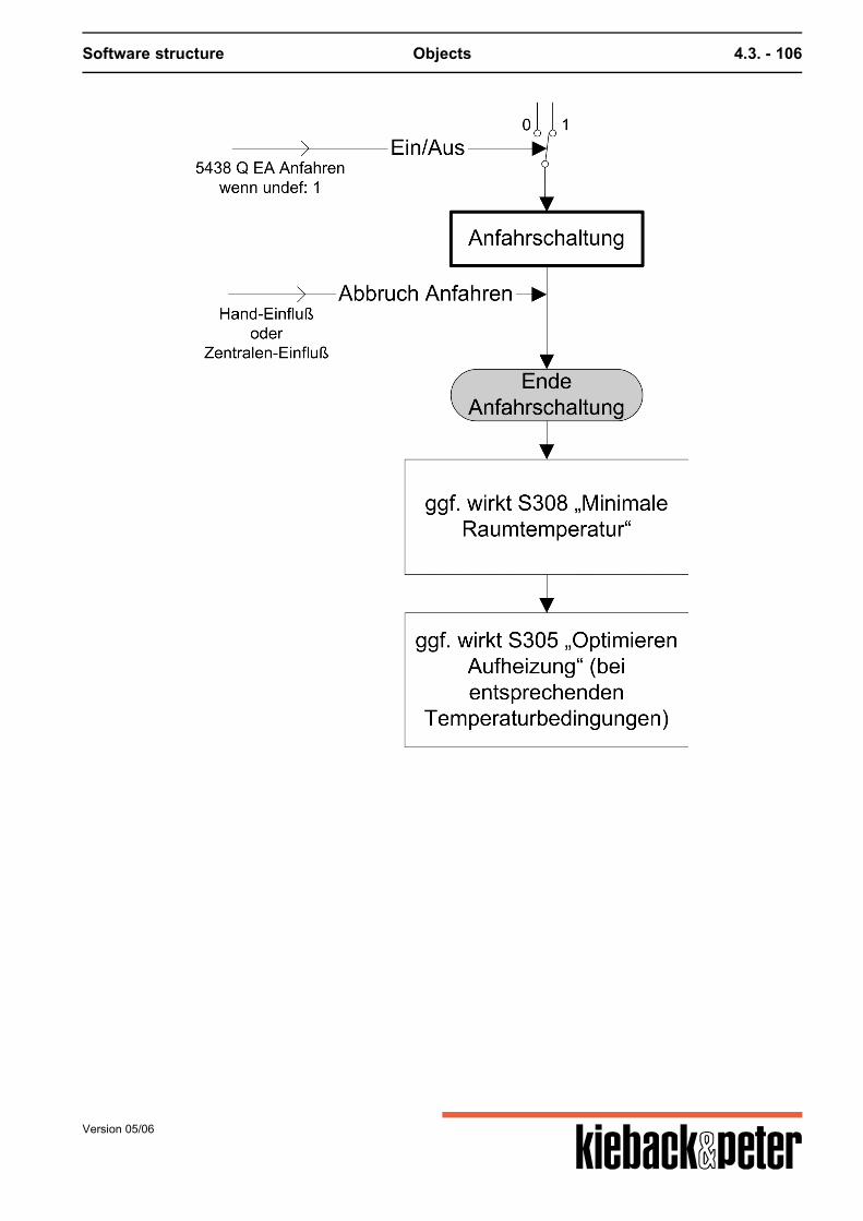
Software structure Objects 4.3. - 106
Version 05/06
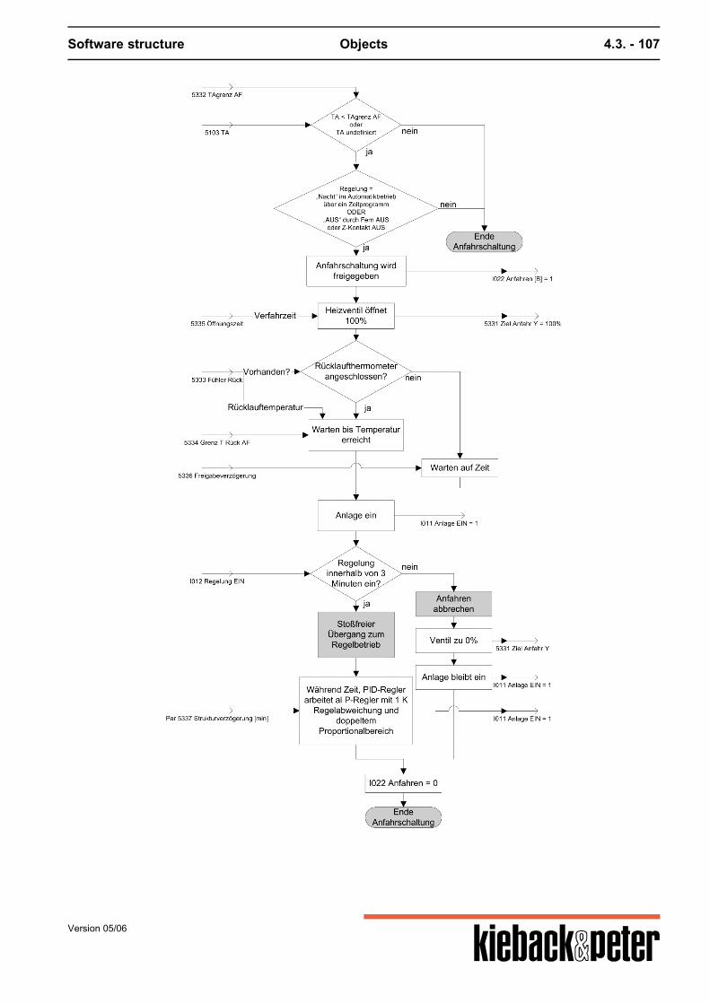
Software structure Objects 4.3. - 107
Version 05/06
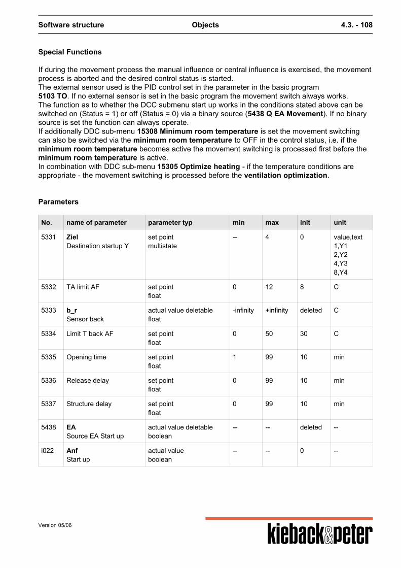
Software structure Objects 4.3. - 108
Special Functions
If during the movement process the manual influence or central influence is exercised, the movementprocess is aborted and the desired control status is started.The external sensor used is the PID control set in the parameter in the basic program5103 TO. If no external sensor is set in the basic program the movement switch always works.The function as to whether the DCC submenu start up works in the conditions stated above can beswitched on (Status = 1) or off (Status = 0) via a binary source (5438 Q EA Movement). If no binarysource is set the function can always operate.If additionally DDC sub-menu 15308 Minimum room temperature is set the movement switchingcan also be switched via the minimum room temperature to OFF in the control status, i.e. if theminimum room temperature becomes active the movement switching is processed first before theminimum room temperature is active.In combination with DDC sub-menu 15305 Optimize heating - if the temperature conditions areappropriate - the movement switching is processed before the ventilation optimization.
Parameters
No. name of parameter parameter typ min max init unit
5331 ZielDestination startup Y
set pointmultistate
-- 4 0 value,text1,Y12,Y24,Y38,Y4
5332 TA limit AF set pointfloat
0 12 8 C
5333 b_rSensor back
actual value deletablefloat
-infinity +infinity deleted C
5334 Limit T back AF set pointfloat
0 50 30 C
5335 Opening time set pointfloat
1 99 10 min
5336 Release delay set pointfloat
0 99 10 min
5337 Structure delay set pointfloat
0 99 10 min
5438 EASource EA Start up
actual value deletableboolean
-- -- deleted --
i022 AnfStart up
actual valueboolean
-- -- 0 --
Version 05/06
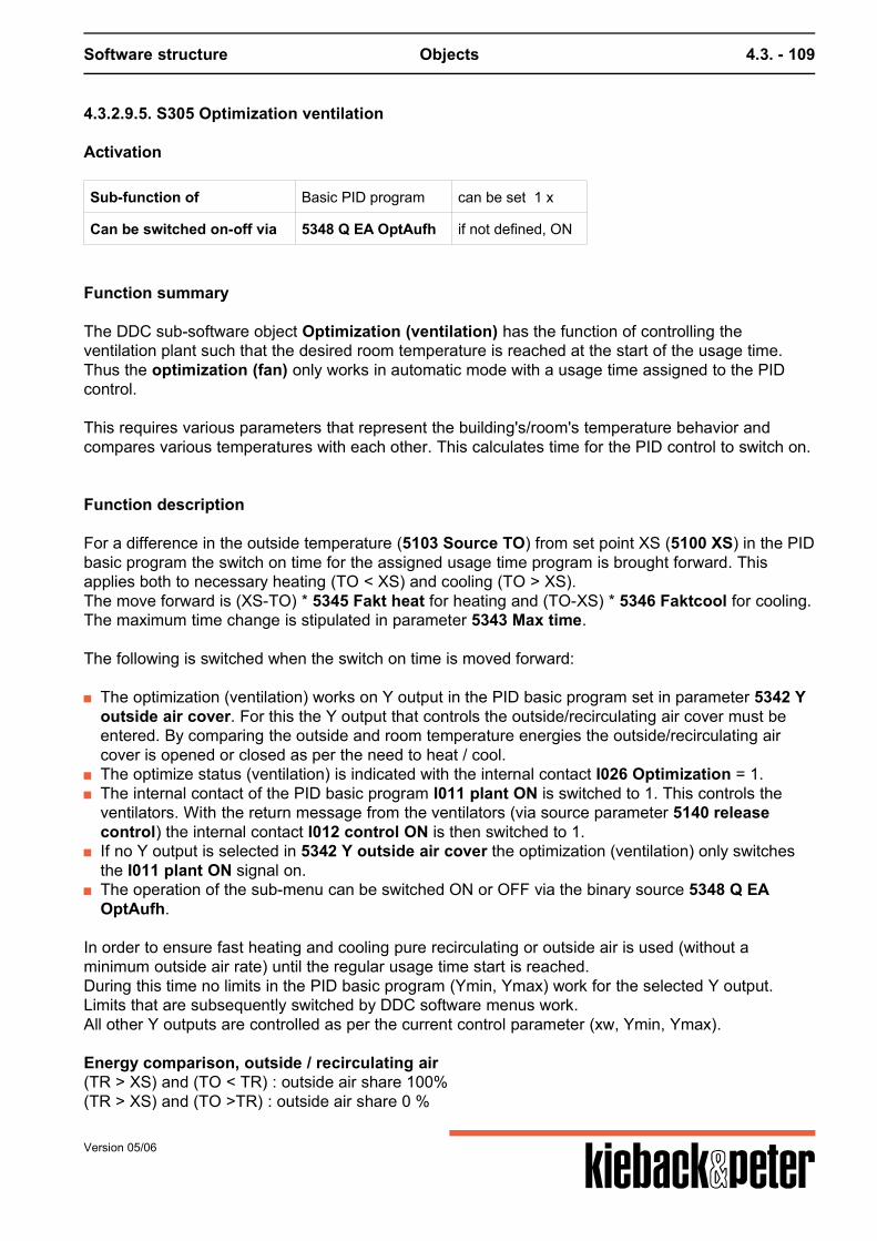
Software structure Objects 4.3. - 109
4.3.2.9.5. S305 Optimization ventilation
Activation
Sub-function of Basic PID program can be set 1 x
Can be switched on-off via 5348 Q EA OptAufh if not defined, ON
Function summary
The DDC sub-software object Optimization (ventilation) has the function of controlling theventilation plant such that the desired room temperature is reached at the start of the usage time.Thus the optimization (fan) only works in automatic mode with a usage time assigned to the PIDcontrol. This requires various parameters that represent the building's/room's temperature behavior andcompares various temperatures with each other. This calculates time for the PID control to switch on.
Function description
For a difference in the outside temperature (5103 Source TO) from set point XS (5100 XS) in the PIDbasic program the switch on time for the assigned usage time program is brought forward. Thisapplies both to necessary heating (TO < XS) and cooling (TO > XS).The move forward is (XS-TO) * 5345 Fakt heat for heating and (TO-XS) * 5346 Faktcool for cooling.The maximum time change is stipulated in parameter 5343 Max time. The following is switched when the switch on time is moved forward:
The optimization (ventilation) works on Y output in the PID basic program set in parameter 5342 Youtside air cover. For this the Y output that controls the outside/recirculating air cover must beentered. By comparing the outside and room temperature energies the outside/recirculating aircover is opened or closed as per the need to heat / cool.
The optimize status (ventilation) is indicated with the internal contact I026 Optimization = 1. The internal contact of the PID basic program I011 plant ON is switched to 1. This controls the
ventilators. With the return message from the ventilators (via source parameter 5140 releasecontrol) the internal contact I012 control ON is then switched to 1.
If no Y output is selected in 5342 Y outside air cover the optimization (ventilation) only switchesthe I011 plant ON signal on.
The operation of the sub-menu can be switched ON or OFF via the binary source 5348 Q EAOptAufh.
In order to ensure fast heating and cooling pure recirculating or outside air is used (without aminimum outside air rate) until the regular usage time start is reached.During this time no limits in the PID basic program (Ymin, Ymax) work for the selected Y output.Limits that are subsequently switched by DDC software menus work.All other Y outputs are controlled as per the current control parameter (xw, Ymin, Ymax). Energy comparison, outside / recirculating air(TR > XS) and (TO < TR) : outside air share 100%(TR > XS) and (TO >TR) : outside air share 0 %
Version 05/06
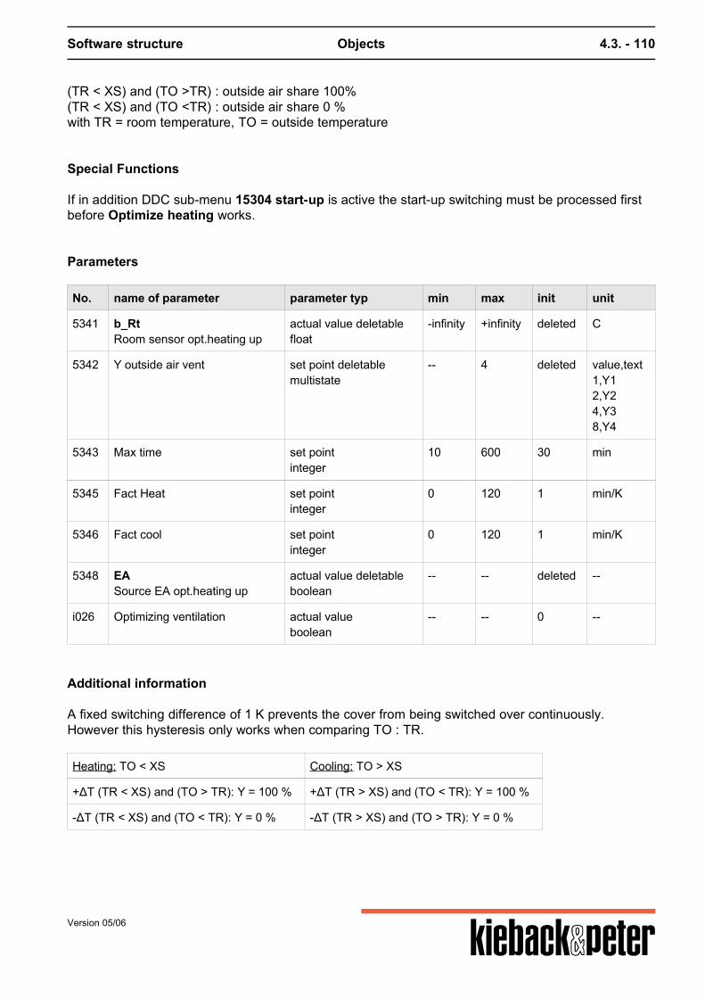
Software structure Objects 4.3. - 110
(TR < XS) and (TO >TR) : outside air share 100%(TR < XS) and (TO <TR) : outside air share 0 %with TR = room temperature, TO = outside temperature
Special Functions
If in addition DDC sub-menu 15304 start-up is active the start-up switching must be processed firstbefore Optimize heating works.
Parameters
No. name of parameter parameter typ min max init unit
5341 b_RtRoom sensor opt.heating up
actual value deletablefloat
-infinity +infinity deleted C
5342 Y outside air vent set point deletablemultistate
-- 4 deleted value,text1,Y12,Y24,Y38,Y4
5343 Max time set pointinteger
10 600 30 min
5345 Fact Heat set pointinteger
0 120 1 min/K
5346 Fact cool set pointinteger
0 120 1 min/K
5348 EASource EA opt.heating up
actual value deletableboolean
-- -- deleted --
i026 Optimizing ventilation actual valueboolean
-- -- 0 --
Additional information
A fixed switching difference of 1 K prevents the cover from being switched over continuously.However this hysteresis only works when comparing TO : TR.
Heating: TO < XS Cooling: TO > XS
+ΔT (TR < XS) and (TO > TR): Y = 100 % +ΔT (TR > XS) and (TO < TR): Y = 100 %
-ΔT (TR < XS) and (TO < TR): Y = 0 % -ΔT (TR > XS) and (TO > TR): Y = 0 %
Version 05/06
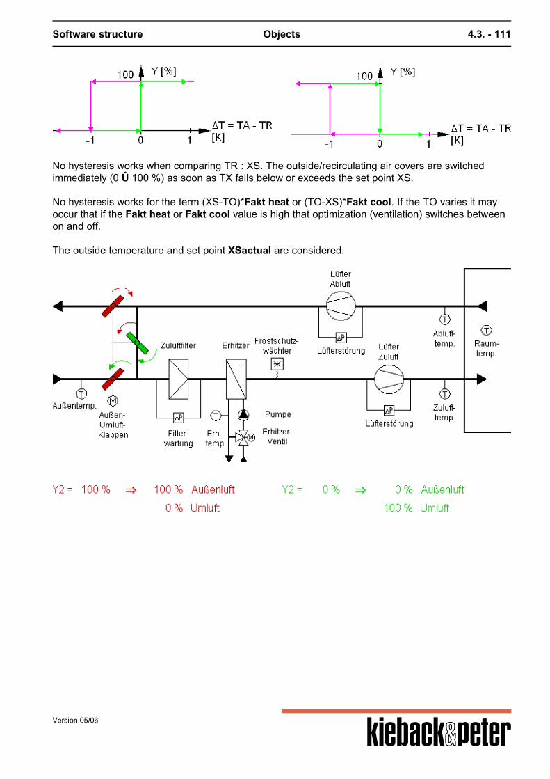
Software structure Objects 4.3. - 111
No hysteresis works when comparing TR : XS. The outside/recirculating air covers are switchedimmediately (0 Û 100 %) as soon as TX falls below or exceeds the set point XS. No hysteresis works for the term (XS-TO)*Fakt heat or (TO-XS)*Fakt cool. If the TO varies it mayoccur that if the Fakt heat or Fakt cool value is high that optimization (ventilation) switches betweenon and off. The outside temperature and set point XSactual are considered.
Version 05/06
Software structure Objects 4.3. - 112
4.3.2.9.6. S306 Free night cooling
Activation
Sub-function of Basic PID program can be set 1 x
Can be switched on-off via 5226 Q EA Free Night if not defined, ON
Function summary
Free night cooling for ventilation plants aims to release the heat in the building by inserting cooloutside air at night. The function can only be used in summer.
The PID basic program moves to " free night cooling" under the following conditions:
The SWO function can be switched ON (Status = 1) orOFF (Status = 0) with a binary source. (5226 Q EA Free Night). Here for example using an annualprogram the menu function can be restricted to certain summer periods. If no binary source is set,the SWO is active.
Summer operation in summer interval.If the average outside temperature 5169 TOaverage exceeds the limiting value 5225 TO limit FN itis assumed to be summer. The internal contact I030 Summer FNK switches to 1. The temperatureof sensor 5103 Source TO is analyzed as the outside temperature.
The outside temperature is at least delta T2 5223 dT2 lower than the room temperature. The room temperature is at least delta T1 5222 dT1 larger than the current room temperature set
point.The current set point 5101 XS current from the PID basic program and the room temperature areanalyzed in line with 5221 Room sensor FN. If no separate room sensor is set the sensor value ofthe basic program 5102 source control variable is analyzed.The room temperature must be above the current set point by 5222 dT1.Parameter I13a becomes logical 1 when the requests stated above are met. Parameter I13acan be be linked further in the DDC system. In contrast to parameter I13 it is not related toSWO PID.
The configuration of the SWO free night cooling depending on the usage time of the SWO PIDoccurs using parameter 5227 observecoolingtime.Observe cooling time = Yes/---:Free night cooling is only active if the remaining outstanding hours to the next plant start as per theset usage times is smaller than the value set in the cooling time parameter.Observe cooling time = No:Stated time conditions are switched off for free night cooling.
The following status condition from the SWO PID must be met:Control mode automatic OFF:Info = 4I11 = plant ON = 0I12 = Control ON = 0Automatic operationRemote On = 0/9/---Remote Off = 0/9/---Z- influenceZ- On = 0/9/---
Version 05/06

Software structure Objects 4.3. - 113
Z-Off = 0/9/---
If all these requests are met the SWO free night cooling works on the relevant SWO PID by switchingon the plant via parameter I11 and the regulator sequences are moved in line with the setting ofparameter YL Wahl FN. The SWO PID does not go to normal operation.
Version 05/06
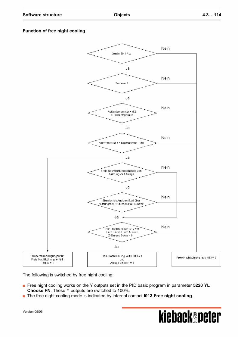
Software structure Objects 4.3. - 114
Function of free night cooling
The following is switched by free night cooling:
Free night cooling works on the Y outputs set in the PID basic program in parameter 5220 YLChoose FN. These Y outputs are switched to 100%.
The free night cooling mode is indicated by internal contact I013 Free night cooling.
Version 05/06
Software structure Objects 4.3. - 115
The internal contact of the PID basic program I011 plant ON is switched to 1. This controls theventilators.
Resetting the free night cooling:
The free night cooling stops if the values in parameters T1 5222 dT1 or 5223 dT2 are lower thanthe fixed switch back difference of 2K or one of the other conditions is no longer met.
Priorities
Free night cooling is prioritized higher in night operation than the control function of the PID basicprogram.In the PID basic program it is not switched to normal operation if the source 5140 Q release controlin the PID basic program is set to 1.
Parameters
No. name of parameter parameter typ min max init unit
5220 YL select FN set pointselection list
-- -- 2 selection listNo.,text0,for Y11,for Y22,for Y33,for Y4
5221 bRoom probe FN
actual value deletablefloat
-infinity +infinity deleted C
5222 dT1dT1
set pointfloat
2 10 2 K
5223 dT2dT2
set pointfloat
2 10 5 K
5224 Cooling time set pointinteger
1 24 3 h
5225 TAgTA limit FN
set pointfloat
0 25 17 C
5226 EAQ EA free Night
actual value deletableboolean
-- -- deleted --
5227 Note cooling times set point deletableboolean
-- -- deleted --
i013 Free night cooling actual valueboolean
-- -- 0 --
i013a Free night cooling possible actual valueboolean
-- -- 0 --
Version 05/06

Software structure Objects 4.3. - 116
No. name of parameter parameter typ min max init unit
i030 SoSummer FNk
actual valueboolean
-- -- 0 --
Version 05/06
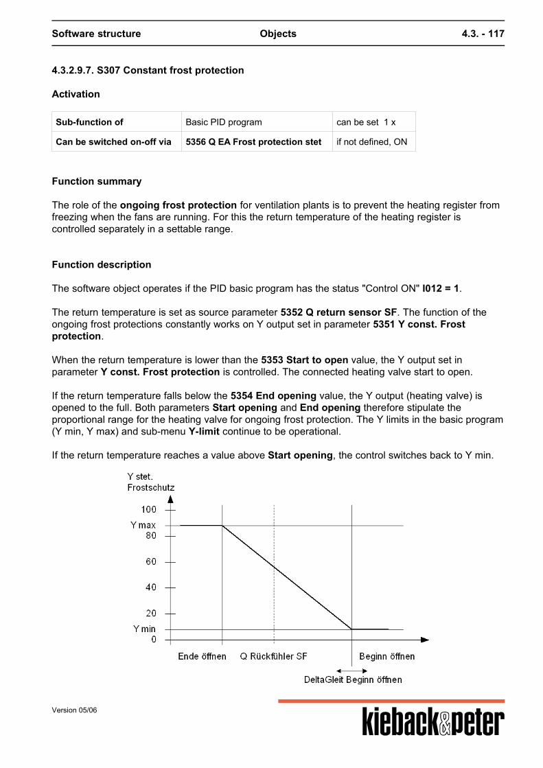
Software structure Objects 4.3. - 117
4.3.2.9.7. S307 Constant frost protection
Activation
Sub-function of Basic PID program can be set 1 x
Can be switched on-off via 5356 Q EA Frost protection stet if not defined, ON
Function summary
The role of the ongoing frost protection for ventilation plants is to prevent the heating register fromfreezing when the fans are running. For this the return temperature of the heating register iscontrolled separately in a settable range.
Function description
The software object operates if the PID basic program has the status "Control ON" I012 = 1.
The return temperature is set as source parameter 5352 Q return sensor SF. The function of theongoing frost protections constantly works on Y output set in parameter 5351 Y const. Frostprotection. When the return temperature is lower than the 5353 Start to open value, the Y output set inparameter Y const. Frost protection is controlled. The connected heating valve start to open. If the return temperature falls below the 5354 End opening value, the Y output (heating valve) isopened to the full. Both parameters Start opening and End opening therefore stipulate theproportional range for the heating valve for ongoing frost protection. The Y limits in the basic program(Y min, Y max) and sub-menu Y-limit continue to be operational. If the return temperature reaches a value above Start opening, the control switches back to Y min.
Version 05/06
Software structure Objects 4.3. - 118
In parameter 5355 deltaglide start opening you can enter a source, e. g. from summer gliding inorder to start the opening earlier depending on the outside temperature. For a lower outsidetemperature the heating register valve is then opened e g. from just 18 °C (for deltaglide startopening = 6 K + Start opening = 12 °C). deltaglide Start opening represent an offset by whichStart opening is moved.This enables you to avoid addressing the frost protection sensor at low temperatures. (Note: In addition the return sensor can be delayed with a attenuation to slow down the menu)
Priorities
If the heating valve's Y output is controlled at the same time by regulating the basic program, thelarger setting signal always takes effect, i. e. a MAX selection operates automatically.
Parameters
No. name of parameter parameter typ min max init unit
5351 YCont. frost protection
set pointmultistate
-- 4 0 value,text1,for Y12,for Y24,for Y38,for Y4
5352 b_rQ back sensor SF
actual value deletablefloat
-infinity +infinity deleted C
5353 Begin open set pointfloat
0 50 12 C
5354 End open set pointfloat
0 50 7 C
5355 deltaSlide begin opening set point deletablefloat
-infinity +infinity deleted K
5356 EAQ EA Frost prot. Cont.
actual value deletableboolean
-- -- deleted --
Calculation
Start opening < Q return sensor CF Y constant Frost protection = Y min End opening < Q return sensor CF < Start opening Y constant Frost protection = (start opening - Q return sensor CF) / (start opening - end opening - (Ymax - Y min) + Y min
Version 05/06

Software structure Objects 4.3. - 119
Q return sensor CF < End opening Y constant Frost protection = Y max Start opening NEW = Start opening + deltaglide start opening
Version 05/06
Software structure Objects 4.3. - 120
4.3.2.9.8. S308 Minimum room temperature
Activation
Sub-function of Basic PID program can be set 1 x
Can be switched on/off via 5364 Q EA minimum room temperature if not defined, ON
Function summary
The purpose of the minimum room temperature DDC software object for ventilation plants is toprevent excessive cooling at night and when the ventilation plant is switched off. I.e. the minimumroom temperature works both in automatic mode out of usage time and when in off mode due toremote OFF or Z contact OFF.
Function description
It can be switched off using the binary source Q_EA Minimum_Room temperature. To monitor the room temperature a sensor must be set in source parameter Q Room sensor MinRT. If the room temperatures fall below the set limiting value TRlimit the following is switched:
The minimum room temperature works on the Y output in the PID basic program set in parameterY room. This output is controlled as per the XS current from the PID basic program.
The minimum room temperature status is displayed with the internal contact Min TR = 1. The internal contact of the PID basic program plant ON is switched to 1.
This controls the ventilators. With the return message from the ventilators (via source parameter Qrelease control) the internal contact Control ON is then switched to 1.The related control however remains OFF, i.e. it only works on the Y output set in parameter Yroom.
If the room temperature rises by 2K above TRlimit, the plant switches off again. Transfer from Min room temp to day regulation:If the circuit is in the Min room temp mode and the usage time assigned to the control circuit and/orthe contact "Remote ON" is activated, the PID control circuit only moves to complete controloperation when the room temperature exceeds TRlimit by 2K.
Special Functions
If in addition the DDC sub.software object S304 start-up is active, the start-up switching must first beworked through before the minimum room temperature is operational.
Version 05/06
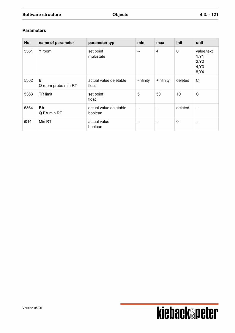
Software structure Objects 4.3. - 121
Parameters
No. name of parameter parameter typ min max init unit
5361 Y room set pointmultistate
-- 4 0 value,text1,Y12,Y24,Y38,Y4
5362 bQ room probe min RT
actual value deletablefloat
-infinity +infinity deleted C
5363 TR limit set pointfloat
5 50 10 C
5364 EAQ EA min RT
actual value deletableboolean
-- -- deleted --
i014 Min RT actual valueboolean
-- -- 0 --
Version 05/06
Software structure Objects 4.3. - 122
4.3.2.9.9. S309 Standstill
Activation
Sub-function of Basic program PID (ventilation) 3 times can be set
Can be switched on/off via 5376 Q EA Standstill control
Function summary
The role of the standstill DDC sub-software object for ventilation plants is to prevent the heatingregister from freezing when the fans stand still. To do so from a particular outside temperature thereturn temperature of the heating register is controlled separately.
Function description
The DDC sub-software object is operational when the PID basic program has the status "Control ON"I12 = 0. The outside temperature recorded in the basic PID program with source parameter source TO iscompared with the limiting value set in TOlimit Frost. As soon as the outside temperature falls belowthis value a separate P control works on the PID control circuit's Y output set in parameter Ystandstill. The connected heating valve start to open.If no outside temperature sensor is installed (set) in the PID basic program the standstill controlfunction is always active when "Control ON" is I12 = 0. The separate P control for the heating valve regulates using a set point XS return and a proportionalrange XP StillstReg. The return temperature with the temperature sensor set in source parameter Qreturn SR is recorded as the current value for the P control.If no return temperature sensor is installed (Set) the Y output is set to 100%. If the outside temperature exceeds the value TOlimit Frost or the PID control is switched on (I12 =1), the control switches back to the original Y signal.The Y limits in the basic program (Ymin, Ymax) and sub-menu Y-limit are not operational. It is alwayscontrolled from 0 .. 100 %.
Version 05/06
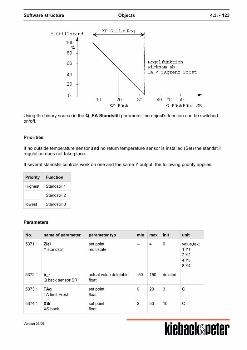
Software structure Objects 4.3. - 123
Using the binary source in the Q_EA Standstill parameter the object's function can be switchedon/off.
Priorities
If no outside temperature sensor and no return temperature sensor is installed (Set) the standstillregulation does not take place. If several standstill controls work on one and the same Y output, the following priority applies:
Priority Function
Highest Standstill 1
Standstill 2
lowest Standstill 3
Parameters
No. name of parameter parameter typ min max init unit
5371.1 ZielY standstill
set pointmultistate
-- 4 0 value,text1,Y12,Y24,Y38,Y4
5372.1 b_rQ back sensor SR
actual value deletablefloat
-50 150 deleted --
5373.1 TAgTA limit Frost
set pointfloat
0 20 3 C
5374.1 XSrXS back
set pointfloat
2 50 10 C
Version 05/06
Software structure Objects 4.3. - 124
No. name of parameter parameter typ min max init unit
5375.1 XPXP standstill reg
set pointfloat
0,5 200 10 C
5376.1 EAQ EA standstill reg
actual value deletableboolean
-- -- deleted --
No. name of parameter parameter typ min max init unit
5371.2 ZielY standstill
set pointmultistate
-- 4 0 value,text1,Y12,Y24,Y38,Y4
5372.2 b_rQ back sensor SR
actual value deletablefloat
-50 150 deleted --
5373.2 TAgTA limit Frost
set pointfloat
0 20 3 C
5374.2 XSrXS back
set pointfloat
2 50 10 C
5375.2 XPXP standstill reg
set pointfloat
0,5 200 10 C
5376.2 EAQ EA standstill reg
actual value deletableboolean
-- -- deleted --
No. name of parameter parameter typ min max init unit
5371.3 ZielY standstill
set pointmultistate
-- 4 0 value,text1,Y12,Y24,Y38,Y4
5372.3 b_rQ back sensor SR
actual value deletablefloat
-50 150 deleted --
5373.3 TAgTA limit Frost
set pointfloat
0 20 3 C
5374.3 XSrXS back
set pointfloat
2 50 10 C
5375.3 XPXP standstill reg
set pointfloat
0,5 200 10 C
5376.3 EAQ EA standstill reg
actual value deletableboolean
-- -- deleted --
Version 05/06
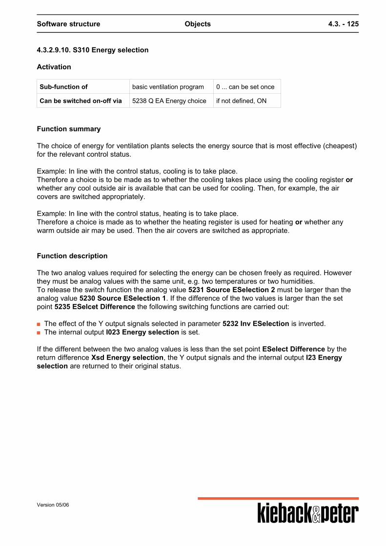
Software structure Objects 4.3. - 125
4.3.2.9.10. S310 Energy selection
Activation
Sub-function of basic ventilation program 0 ... can be set once
Can be switched on-off via 5238 Q EA Energy choice if not defined, ON
Function summary
The choice of energy for ventilation plants selects the energy source that is most effective (cheapest)for the relevant control status. Example: In line with the control status, cooling is to take place.Therefore a choice is to be made as to whether the cooling takes place using the cooling register orwhether any cool outside air is available that can be used for cooling. Then, for example, the aircovers are switched appropriately. Example: In line with the control status, heating is to take place.Therefore a choice is made as to whether the heating register is used for heating or whether anywarm outside air may be used. Then the air covers are switched as appropriate.
Function description
The two analog values required for selecting the energy can be chosen freely as required. Howeverthey must be analog values with the same unit, e.g. two temperatures or two humidities.To release the switch function the analog value 5231 Source ESelection 2 must be larger than theanalog value 5230 Source ESelection 1. If the difference of the two values is larger than the setpoint 5235 ESelcet Difference the following switching functions are carried out:
The effect of the Y output signals selected in parameter 5232 Inv ESelection is inverted. The internal output I023 Energy selection is set.
If the different between the two analog values is less than the set point ESelect Difference by thereturn difference Xsd Energy selection, the Y output signals and the internal output I23 Energyselection are returned to their original status.
Version 05/06
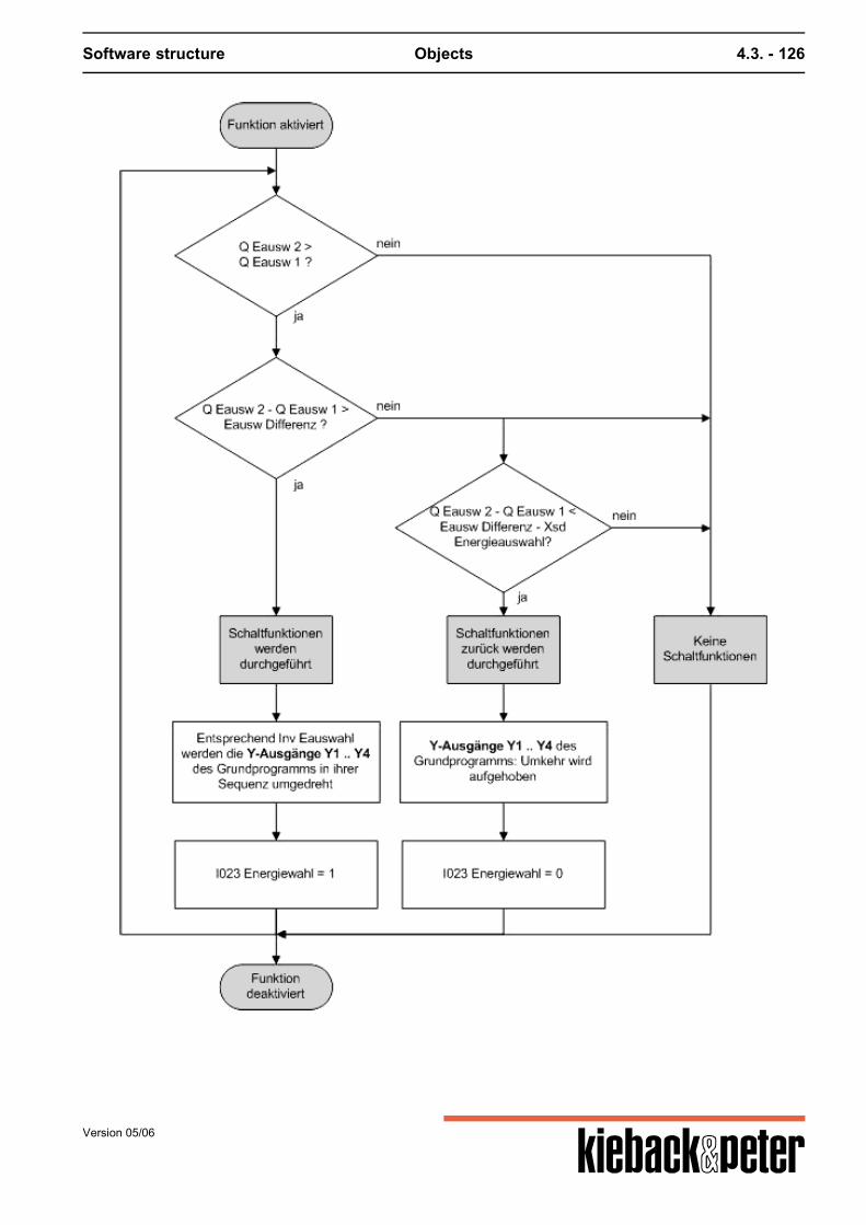
Software structure Objects 4.3. - 126
Version 05/06
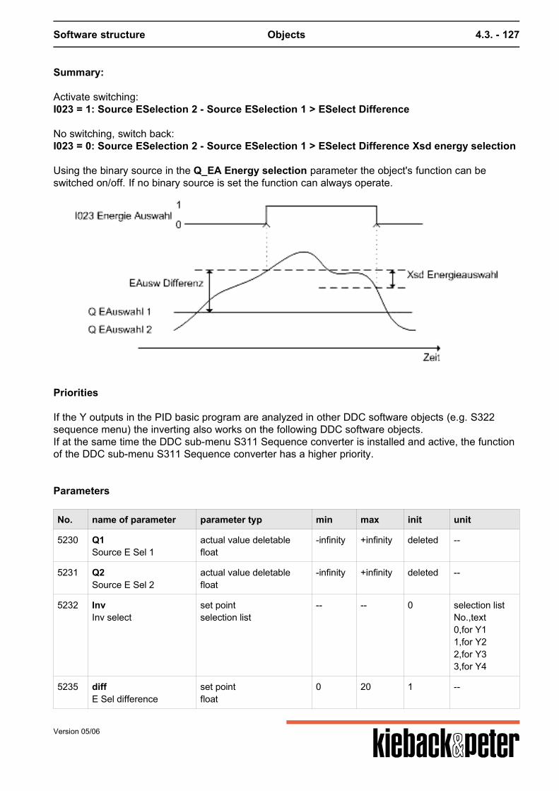
Software structure Objects 4.3. - 127
Summary:
Activate switching:I023 = 1: Source ESelection 2 - Source ESelection 1 > ESelect Difference No switching, switch back:I023 = 0: Source ESelection 2 - Source ESelection 1 > ESelect Difference Xsd energy selection Using the binary source in the Q_EA Energy selection parameter the object's function can beswitched on/off. If no binary source is set the function can always operate.
Priorities
If the Y outputs in the PID basic program are analyzed in other DDC software objects (e.g. S322sequence menu) the inverting also works on the following DDC software objects.If at the same time the DDC sub-menu S311 Sequence converter is installed and active, the functionof the DDC sub-menu S311 Sequence converter has a higher priority.
Parameters
No. name of parameter parameter typ min max init unit
5230 Q1Source E Sel 1
actual value deletablefloat
-infinity +infinity deleted --
5231 Q2Source E Sel 2
actual value deletablefloat
-infinity +infinity deleted --
5232 InvInv select
set pointselection list
-- -- 0 selection listNo.,text0,for Y11,for Y22,for Y33,for Y4
5235 diffE Sel difference
set pointfloat
0 20 1 --
Version 05/06

Software structure Objects 4.3. - 128
No. name of parameter parameter typ min max init unit
5237 xsdXsd Energy select
set pointfloat
0 10 2 --
5238 EAQ EA Energy select
actual value deletableboolean
-- -- deleted --
i023 Energy select actual valueboolean
-- -- 0 --
Version 05/06
Software structure Objects 4.3. - 129
4.3.2.9.11. S311 Sequence change
Activation
Sub-function of Basic program PID (ventilation) can be set 1 x
Function summary
The purpose of the sub-software object S311 sequence converter is to switch the operating directionof the Y outputs in the basic program depending on particular plant statuses.
Function description
In parameters 5240 source SP YL1 to 5243 source SP YL4 a binary source is set. If the binary source signal switches from 0 to 1 or 1 to 0 the corresponding Y outputs YL1 to YL4 onthe PID basic program are switched to inverted or back again. No inverting takes place if the binarysource is invalid. If access is made on the Y output in the PID basic program in other DDC software objects theinverted direction is adopted. The limits of the Y outputs on the PID basic program 5141 Y1 min to 5148 4 max are stilloperational. E.g. if a Y output works with the limits 20 - 100 %, the inverted Y output also works withthese limits.
Priorities
If the DDC sub-menu M310 energy selection is installed and active at the same time the function ofthe DDC sub-menu M311 sequence reversal is prioritized higher.
Parameters
No. name of parameter parameter typ min max init unit
5240 QY1Source SU YL1
actual value deletableboolean
-- -- deleted --
5241 QY2Source SU YL2
actual value deletableboolean
-- -- deleted --
5242 QY3Source SU YL3
actual value deletableboolean
-- -- deleted --
5243 QY4Source SU YL4
actual value deletableboolean
-- -- deleted --
Version 05/06
Software structure Objects 4.3. - 130
4.3.2.9.12. S312 Limitation
Activation
Sub-function of basic heating and ventilation program 0 ... can be set 2 x
Can be switched on-off via 5279 Q EA limitation if not defined, ON
Function summary
The DDC control function of the main control circuit is restricted using DDC software object limitation.The limitation is required for example:
for keeping the supply air temperature in ventilation controls in comfortable limits to curb the supply temperature in heating controls before reaching technological limiting values.
A max or min limit is possible in line with the requests. The max or min limits may glide in line with a command value. E.g. if for ventilation controls, besidelifting the room´s set point depending on the outside temperature, concurrently min limit of the supplyair is lifted.
Function description
In the DDC software object limitation the selected limitation sensor in the source parameter5270 Q limitation sensor is set. The limitation value is set with parameter5271 limitation value. Parameter 5272 limitation sets whether this is a max or a min limiting value. The limitation works in the following 2 phases: a) The value of the limitation sensor nears the max or min limitation value.b) The value of the limitation sensor is higher or lower than the max or min limitation value. Re a) the limitation function is adopted gliding. The variance of the limitation sensor to the limitationvalue is compared with the main control variance of the basic program. Depending on the relevantcontrol variance control is still made with the main control circuit XP. Re b) if the set Max limitation value is exceeded or the number falls below the min limitation value allXPs on the control circuit are replaced by 5273 XPlimitation in order control the limitation valueinfringement as quickly as possible. This control status is indicated by switching the internal contactV10 limitation and I020 XP switching from "0" to "1". Limiting value glide can occur for both the min. and max limiting values using command value sourceparameter 5275 command value limit. The range in which the min and max limits should glide is stipulated by parameters 5277 glide startlimit and 5278 glide end limit. The influence of gliding is set by parameter 5276 EFg. If 5276 EFg =0, glide does not occur. If inverting is set winter compensation takes place, i.e. the limiting value is raised if the commandvalue falls below the value of 5278 glide end limit.
Version 05/06
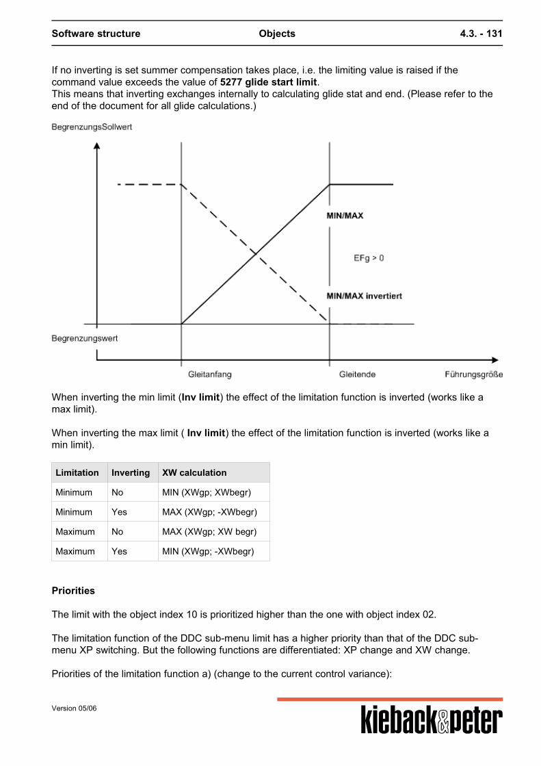
Software structure Objects 4.3. - 131
If no inverting is set summer compensation takes place, i.e. the limiting value is raised if thecommand value exceeds the value of 5277 glide start limit.This means that inverting exchanges internally to calculating glide stat and end. (Please refer to theend of the document for all glide calculations.)
When inverting the min limit (Inv limit) the effect of the limitation function is inverted (works like amax limit). When inverting the max limit ( Inv limit) the effect of the limitation function is inverted (works like amin limit).
Limitation Inverting XW calculation
Minimum No MIN (XWgp; XWbegr)
Minimum Yes MAX (XWgp; -XWbegr)
Maximum No MAX (XWgp; XW begr)
Maximum Yes MIN (XWgp; -XWbegr)
Priorities
The limit with the object index 10 is prioritized higher than the one with object index 02. The limitation function of the DDC sub-menu limit has a higher priority than that of the DDC sub-menu XP switching. But the following functions are differentiated: XP change and XW change. Priorities of the limitation function a) (change to the current control variance):
Version 05/06
Software structure Objects 4.3. - 132
Priority Function
Highest S312.1 Limitation 1
S303 Cascade (only PID)
lowest S312.2 Limitation 2
The current control variance is determined as follows:
1. XWcurrent = Limitation 2 (XWbasic program, XWlimitation2)2. XWcurrent = cascade (XWcurrent, XWcascade) (only PID)3. XWcurrent = Limitation 1 (XWcurrent, XWlimitation1)
Priorities of the limitation function b) (change to the XP range):
Priority Function
Highest S312.1 Limitation 1
S312.2 Limitation 2
lowest S317 XP conversion
Parameters
No. name of parameter parameter typ min max init unit
5270.1 QQ limitation sensor
actual value deletablefloat
-infinity +infinity deleted --
5271.1 Limitation value set pointfloat
-infinity +infinity 150 --
5272.1 Limitation set pointmultistate
-- 2 1 value,text0,Minimum1,Maximum
5273.1 XP1XP limitation
set pointfloat
0,5 200 10 --
5274.1 invInv. limitation
set pointboolean
-- -- 0 --
5275.1 Q_FgLead size limit
actual value deletablefloat
-infinity +infinity deleted --
5276.1 EFgEFg
set pointfloat
-10 10 0 --
5277.1 AnfSlide begin limit
set pointinteger
-50 150 22 --
Version 05/06

Software structure Objects 4.3. - 133
No. name of parameter parameter typ min max init unit
5278.1 EndSlide end limit
set pointinteger
-50 150 32 --
5279.1 EAQ EA limitation
actual value deletableboolean
-- -- deleted --
v10.1 Limitation actual valueboolean
-- -- 0 --
No. name of parameter parameter typ min max init unit
5270.2 QQ limitation sensor
actual value deletablefloat
-infinity +infinity deleted --
5271.2 Limitation value set pointfloat
-infinity +infinity 150 --
5272.2 Limitation set pointmultistate
-- 2 1 value,text0,Minimum1,Maximum
5273.2 XP2XP limitation
set pointfloat
0,5 200 10 --
5274.2 invInv. limitation
set pointboolean
-- -- 0 --
5275.2 Q_FgLead size limit
actual value deletablefloat
-infinity +infinity deleted --
5276.2 EFgEFg
set pointfloat
-10 10 0 --
5277.2 AnfSlide begin limit
set pointinteger
-50 150 22 --
5278.2 EndSlide end limit
set pointinteger
-50 150 32 --
5279.2 EAQ EA limitation
actual value deletableboolean
-- -- deleted --
v10.2 Limitation actual valueboolean
-- -- 0 --
Version 05/06
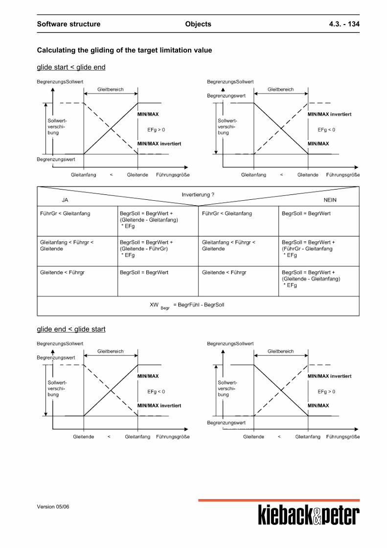
Software structure Objects 4.3. - 134
Calculating the gliding of the target limitation value
glide start < glide end
glide end < glide start
Version 05/06

Software structure Objects 4.3. - 135
Version 05/06
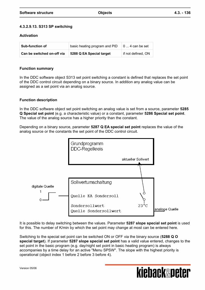
Software structure Objects 4.3. - 136
4.3.2.9.13. S313 SP switching
Activation
Sub-function of basic heating program and PID 0 ... 4 can be set
Can be switched on-off via 5288 Q EA Special target if not defined, ON
Function summary
In the DDC software object S313 set point switching a constant is defined that replaces the set pointof the DDC control circuit depending on a binary source. In addition any analog value can beassigned as a set point via an analog source.
Function description
In the DDC software object set point switching an analog value is set from a source, parameter 5285Q Special set point (e.g. a characteristic value) or a constant, parameter 5286 Special set point.The value of the analog source has a higher priority than the constant. Depending on a binary source, parameter 5287 Q EA special set point replaces the value of theanalog source or the constants the set point of the DDC control circuit.
It is possible to delay switching between the values. Parameter 5287 slope special set point is usedfor this. The number of K/min by which the set point may change at most can be entered here. Switching to the special set point can be switched ON or OFF via the binary source (5288 Q Ospecial target). If parameter 5287 slope special set point has a valid value entered, changes to theset point in the basic program (e.g. day/night set point in basic heating program) is alwaysaccompanies by a time delay for an active "Menu SPSW". The slope with the highest priority isoperational (object index 1 before 2 before 3 before 4).
Version 05/06
Software structure Objects 4.3. - 137
Priorities
Object index 1 has the highest priority, menu index 4 has the lowest priority.
1. Set point switching 1 15313.12. Set point switching 2 15313.23. Set point switching 3 15313.34. Set point switching 4 15313.45. Set point remote control 153166. Set point correction 15315
Note
Basic heating program:In the basic heating program the set point switching replaces the calculate TStarget current from thebasic program or the target room value TR target for the set DDC sub-menu 15318 room correctionand/or 15300 optimize. Switching to a firm TS target/TR target excludes night falls. If the optimizesub-menu is active the new TR target influences intermediate heating, pre-lowering, preset, theheating up time and the adaptions. Basic PID program:In the PID basic program for active set point switching the current set point XS current is overwritten.If in addition to the basic program the DDC software object S314 set point glide also works thiscalculated XS current is overwritten.
Parameters
No. name of parameter parameter typ min max init unit
5285.1 Q-XSQ Sondersollwert
actual value deletablefloat
-50 150 deleted C
5286.1 XScustom setpoint
set pointfloat
-50 150 0 C
5287.1 K/minQ EA custom setpoint
set point deletablefloat
0,1 60 deleted K/min
5288.1 EAQ EA custom setpoint
actual value deletableboolean
-- -- deleted --
No. name of parameter parameter typ min max init unit
5285.2 Q-XSQ Sondersollwert
actual value deletablefloat
-50 150 deleted C
5286.2 XScustom setpoint
set pointfloat
-50 150 0 C
5287.2 K/minQ EA custom setpoint
set point deletablefloat
0,1 60 deleted K/min
Version 05/06
Software structure Objects 4.3. - 138
No. name of parameter parameter typ min max init unit
5288.2 EAQ EA custom setpoint
actual value deletableboolean
-- -- deleted --
No. name of parameter parameter typ min max init unit
5285.3 Q-XSQ Sondersollwert
actual value deletablefloat
-50 150 deleted C
5286.3 XScustom setpoint
set pointfloat
-50 150 0 C
5287.3 K/minQ EA custom setpoint
set point deletablefloat
0,1 60 deleted K/min
5288.3 EAQ EA custom setpoint
actual value deletableboolean
-- -- deleted --
No. name of parameter parameter typ min max init unit
5285.4 Q-XSQ Sondersollwert
actual value deletablefloat
-50 150 deleted C
5286.4 XScustom setpoint
set pointfloat
-50 150 0 C
5287.4 K/minQ EA custom setpoint
set point deletablefloat
0,1 60 deleted K/min
5288.4 EAQ EA custom setpoint
actual value deletableboolean
-- -- deleted --
Version 05/06
Software structure Objects 4.3. - 139
4.3.2.9.14. S314 Set point glide
Activation
Sub-function of Basic PID program can be set 1 x
Can be switched on-off via 5254 Q EA Gliding if not defined, ON
Function summary
The function of the DDC sub-software function set point glide is to allow the set point to glide with acommand value. At the same time a range in which the glide is permitted can be set.
Function description
A guidance signal parameter 5250 command value SG the current set point5101 XS current in the PID basic program is raised or lowered. Any analog value in the DDC4000system (e.g. outside temperature) can be selected as a guidance signal. The command value only results in a change to the set point within a glide range. The glide range isstipulated by the parameters 5251 glide start SG and 5252 glide end SG. The influence of the guidance signal on the limiting value change is determined with the parameter5253 INF. If Inf is negative this can force a reduction in the set point. Parameter 5255 Delta SP gliding is an actual value and shows the difference of the current set pointthat results from the DDC sub-menu set point gliding. The function of the DDC software object can be switched ON (Status = 1) or OFF (Status = 0) with abinary source (Status = 0). (5254 Q EA Gliding)If no binary source is set the function is switched to ON.
Based on the start and end of glide-ing the following calculation arises for the set point gliding: glide start < glide end comvalue < glide start: Delta_glide = 0 glide start< comvalue < glide end: Delta_glide = EF * (comvalue - glide start) glide end < comvalue: Delta_glide = EF * (glide end - glide start) glide end < glide start comvalue < glide end: Delta_glide = EF * (glide start - glide end) glide end < comvalue < glide start: Delta_glide = EF * (glide start - comvalue) glide start < comvalue: Delta_glide = 0 Set point = XS current (basic program) + Delta_glide command value < glide start : Set point = XS (basic program) glide start < command value < glide end : Set point = XS (basic program) + Delta_glide Delta_glide = EF * (comvalue - glide start)
Version 05/06
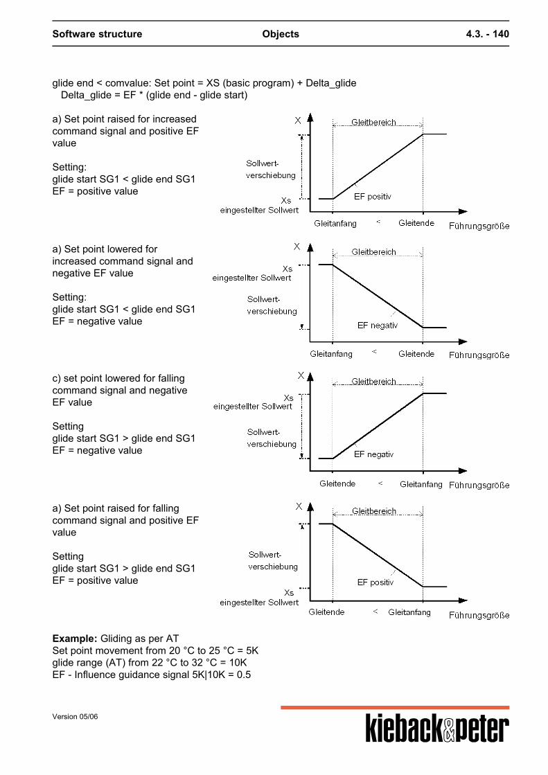
Software structure Objects 4.3. - 140
glide end < comvalue: Set point = XS (basic program) + Delta_glide Delta_glide = EF * (glide end - glide start)
a) Set point raised for increasedcommand signal and positive EFvalue Setting:glide start SG1 < glide end SG1EF = positive value
a) Set point lowered forincreased command signal andnegative EF value Setting:glide start SG1 < glide end SG1EF = negative value
c) set point lowered for fallingcommand signal and negativeEF value Settingglide start SG1 > glide end SG1EF = negative value
a) Set point raised for fallingcommand signal and positive EFvalue Settingglide start SG1 > glide end SG1EF = positive value
Example: Gliding as per ATSet point movement from 20 °C to 25 °C = 5Kglide range (AT) from 22 °C to 32 °C = 10KEF - Influence guidance signal 5K|10K = 0.5
Version 05/06

Software structure Objects 4.3. - 141
The DDC sub-software object set point glide not only works on the XSactual, but also moves thesupply air min. limitation of the cascade if parameter 5207 gliding cascade is set to "YES".
Note
On the PID basic program for active set point glide the current set point XS current is overwritten.
Priorities
If in addition to the basic program the DDC sub-menu cascade is also working the supply air min limitis moved by the same amount at the same time if parameter 5207 gliding cascade is set to "yes". If in addition to the basic program the DDC sub-menu set point switching is also operational than onlythe set point switching is operational.
Parameters
No. name of parameter parameter typ min max init unit
5250 Lead size SG actual value deletablefloat
-infinity +infinity deleted --
5251 AnfSlide start SG
set pointfloat
-infinity +infinity 22 --
5252 EndSlide end SG
set pointfloat
-infinity +infinity 32 --
5253 EFEF SG
set pointfloat
-10 10 0,5 --
5254 EAQ EA sliding
actual value deletableboolean
-- -- deleted --
5255 DeltaDelta SW sliding
actual valuefloat
-infinity +infinity 0 --
Version 05/06

Software structure Objects 4.3. - 142
4.3.2.9.15. S315 Set point correction
Activation
Sub-function of basic heating program and PID 0 ... can be set once
Can be switched on-off via 5292 Q EA Target correction if not defined, ON
Function summary
DDC software object S315 address an analog source to which the set point correction control isconnected or from which any analog value can be read. This analog value works as a correction onthe DDC control circuit set point.
Function description
Parameter source target correction 0..100 % sets the analog value of a set point correction controlor any analog value of the DDC4000 system. The value range produced by this analog source isinterpreted as 0 ... 100%. (Effect like source target correction in the DDC3000) The value range for the set point correction is set with parameters upper limit release SPC andlower limit release SPC. The measuring unit of this range is matched automatically to themeasuring unit of the set point being corrected. SPC = (release SPC UL - release SPC LL) / 100 * Q SPC (in 0..100 %) + release SPC LL Parameter source target correction absolute value sets the analog value of a set point correctioncontrol or any analog value of the DDC4000 system. The value range produced from this analogsource is processed as a real value, e.g. -5..5 K. The imported value is kept in the upper limit release SPC and lower limit release SPC limits.Higher/lower values are cut off. The source target correction absolute value has a higher prioritythan source target correction 0..100 %. The function of the DDC sub-menu can be switched ON (Status = 1) or OFF (Status = 0) with abinary source. ( Q EA Target correction)If no binary source is set the function is switched to ON.
Priorities
If in addition to the DDC software object set point correction a DDC software object set pointswitching and/or set point remote control is active, the following priorities apply:
Priority Function
Highest Set point switch 1 S313.1
Set point switch 2 S313.2
Version 05/06

Software structure Objects 4.3. - 143
Priority Function
Set point switch 3 S313.3
Set point switch 4 S313.4
Set point remote control S316
lowest Set point correction S315
Example
DDC control circuit setpoint to be corrected
Lower limit SPC release Upper limit SPC release valid range for a setpoint correction
20°C -4 6 16 °C to 26 °C
5mBar 0 2 5 mBar to 7 mBar
Note
Basic heating program:The DDC submenu set point correction only works for "day regulation".The set point correction influences KH (parallel movement of heating curve) if the DDC sub-menu15318 room correction or 15300 optimization is not active. TStarget new = TStarget + target correction If DDC room correction or optimize sub-menus are active the room set point TRtarget is changed bythe set point correction. This, for example, influences the economy function and the start set point foractive room correction. TRtarget new = TRtarget + target correction Room correction: TStarget new = TStarget -(Roomtemp – TRtarget new) * ER correction Optimization: NO TStarget correction Basic PID program:In this basic program the set point correction works on the current set point XS current.XS current new = XS current + target correction
Parameters
No. name of parameter parameter typ min max init unit
5290 Q100Q EA Setpoint Correction
actual value deletablefloat
0 100 deleted %
Version 05/06

Software structure Objects 4.3. - 144
No. name of parameter parameter typ min max init unit
5291 QSource Setpoint Correction
actual value deletablefloat
-infinity +infinity deleted --
5292 EAQ EA Setpoint Correction
actual value deletableboolean
-- -- deleted --
5293 release SWK set pointfloat
-infinity +infinity -5 K
5294 Release SWK above set pointfloat
-infinity +infinity 5 --
Version 05/06
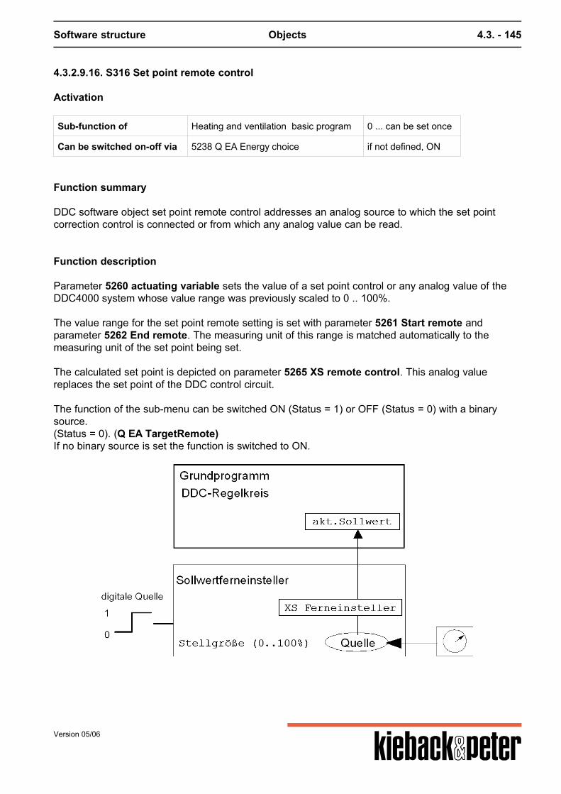
Software structure Objects 4.3. - 145
4.3.2.9.16. S316 Set point remote control
Activation
Sub-function of Heating and ventilation basic program 0 ... can be set once
Can be switched on-off via 5238 Q EA Energy choice if not defined, ON
Function summary
DDC software object set point remote control addresses an analog source to which the set pointcorrection control is connected or from which any analog value can be read.
Function description
Parameter 5260 actuating variable sets the value of a set point control or any analog value of theDDC4000 system whose value range was previously scaled to 0 .. 100%. The value range for the set point remote setting is set with parameter 5261 Start remote andparameter 5262 End remote. The measuring unit of this range is matched automatically to themeasuring unit of the set point being set. The calculated set point is depicted on parameter 5265 XS remote control. This analog valuereplaces the set point of the DDC control circuit. The function of the sub-menu can be switched ON (Status = 1) or OFF (Status = 0) with a binarysource.(Status = 0). (Q EA TargetRemote)If no binary source is set the function is switched to ON.
Version 05/06

Software structure Objects 4.3. - 146
Priorities
If in addition to the DDC software object set point remote control a DDC software object set pointswitching and/or set point correction is active, the following priorities apply:
Priority Function
Highest S313.1 Set point switch 1
S313.2 Set point switch 2
S313.3 Set point switch 3
S313.4 Set point switch 4
S316 Set point remote control
lowest S315 Set point correction
Example:
5261 Start remote 5262 End remote 5265 XS remote control at 0 ..100% value change
10 °C 25 °C 10 °C .. 25 °C
20 %rF 80 %rF 20 %rF .. 80 %rF
0 mBar 5 mBar 0 mBar .. 5 mBar
Note
Basic heating program:The DDC submenu set point correction only works for "day regulation". The set point correction influences KH (parallel movement of heating curve) if the DDC softwareobject S318 room correction or S300 optimization is not active. TStarget correction = XS remote control = (End remote - start remote) * actuating variable / 100 % +start remote TStargetnew = TStarget + TStarget correction If the DDC software object room correction or optimize are active the room set point TRtarget ischanged by the XS remote control. This, for example, influences the economy function and the startset point for active room correction. Room correction: TStargetcorrection = (Room temp - XS remote control) * ER Optimization: NO TStarget correction Basic PID program:In this basic program the set point remote control works on the current set point XS current.
Version 05/06
Software structure Objects 4.3. - 147
XS current = XS remote control = (End remote - start remote) * actuating variable / 100 % + startremote
Parameters
No. name of parameter parameter typ min max init unit
5260 Set size actual value deletablefloat
0 100 deleted --
5261 AnfBegin remote
set pointinteger
-2147483648 2147483647 0 --
5262 EndEnd remote
set pointinteger
-2147483648 2147483647 50 --
5263 EAQ EA setpoint remote
actual value deletableboolean
-- -- deleted --
5265 XS Remote setting actual valuefloat
-infinity +infinity 0 --
Version 05/06
Software structure Objects 4.3. - 148
4.3.2.9.17. S317 XP switching
Activation
Sub-function of basic heating program and PID 0 ... can be set once
Can be switched on-off via 5306 Q XP switching if not defined, ON
Function summary
DDC control circuit control setting parameters are switched with the DDC sub-menu XP switching.Depending on a binary source the proportional ranges of the Y outputs, the rate and regulatingperiods can be switched.
Function description
The binary source is set in parameter source XP switching.If the digital source Q XP switching is "1" or "---" the controller setting parameters are replaced bythe set setting values.The working XP switching is displayed via internal contact I20 XP switching in the basic heatingprogram or PID. Note:In the basic heating program I20 XP switching only becomes "1" if XPY1 changes. Only changes TNNew and/or rate New; I20 XP switch remains "0". I20 XP switch can also be "1" as a result of alimit.
Priorities
The DDC sub-menus limitation menus 1 and 2 work before the XP switch.
Priority Function
Highest Limitation 1 S312.1
Cascade (only PID) S303
Limitation 2 S312.2
XP switching S317
lowest Structure delay start-up S304
Special Functions
Depending on the reset time tN set in the basic program theXPY (basic program) is switched to the XPY (XP switching) gliding and vice versa.
Version 05/06
Software structure Objects 4.3. - 149
Parameters
No. name of parameter parameter typ min max init unit
5300 XPY1XPY1 New
set pointfloat
0,5 999,9 50 K
5301 XPY2XPY2 New
set pointfloat
0,5 999,9 50 K
5302 XPY3XPY3 New
set pointfloat
0,5 999,9 50 K
5303 XPY4XPY4 New
set pointfloat
0,5 999,9 50 K
5304 tNTn New
set point deletablefloat
0,5 99 3 min
5305 dVorhalt
set point deletableinteger
1 99 deleted s
5306 QQ XP change overR
actual value deletableboolean
-- -- deleted --
i020 XP Changeover actual valueboolean
-- -- 0 --
Version 05/06
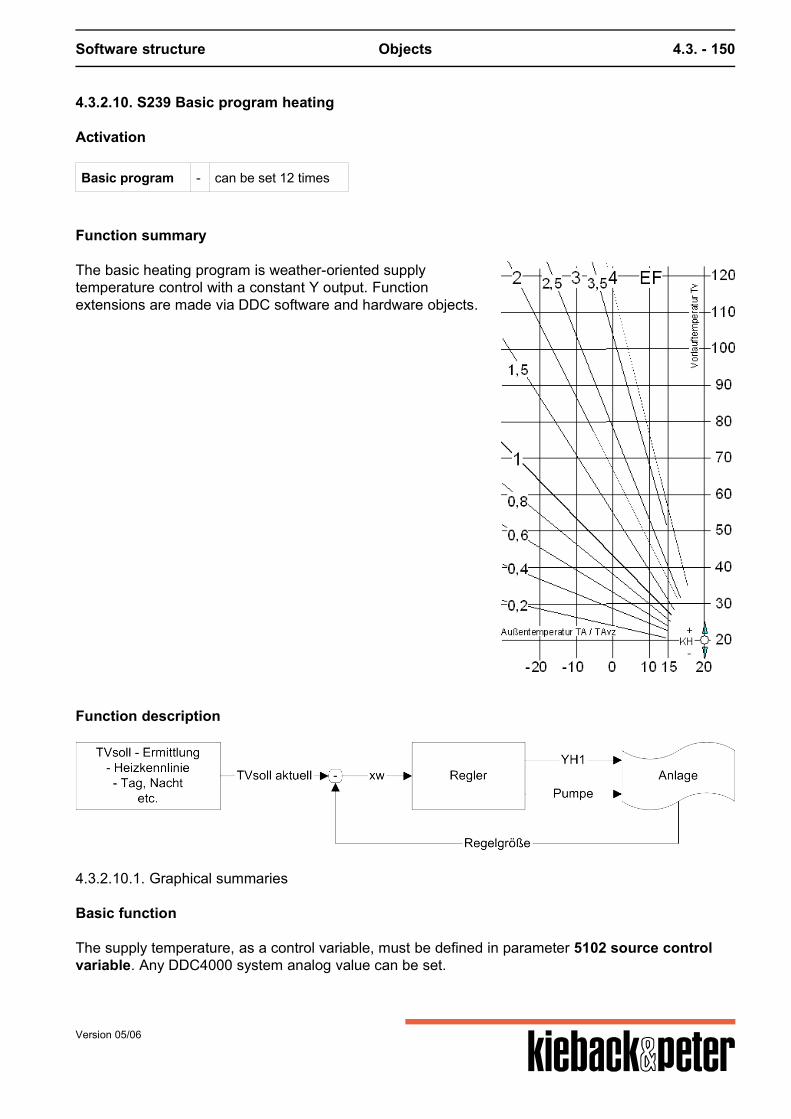
Software structure Objects 4.3. - 150
4.3.2.10. S239 Basic program heating
Activation
Basic program - can be set 12 times
Function summary
The basic heating program is weather-oriented supplytemperature control with a constant Y output. Functionextensions are made via DDC software and hardware objects.
Function description
4.3.2.10.1. Graphical summaries
Basic function The supply temperature, as a control variable, must be defined in parameter 5102 source controlvariable. Any DDC4000 system analog value can be set.
Version 05/06
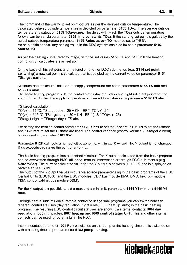
Software structure Objects 4.3. - 151
The command of the warm-up set point occurs as per the delayed outside temperature. Thecalculated delayed outside temperature is depicted on parameter 5153 TOvz. The average outsidetemperature is output on 5169 TOaverage. The delay with which the TOvz outside temperaturefollows can be set via parameter 5168 time constants TOvz. If the starting set point is guided by theactual outside temperature parameter 5152 Rules as per TO must be set to "YES".As an outside sensor, any analog value in the DDC system can also be set in parameter 5103source TO. As per the heating curve (refer to image) with the set values 5155 EF and 5156 KH the heatingcontrol circuit calculates a start set point.
On the basis of this set point and the function of other DDC sub-menus (e.g. S314 set pointswitching) a new set point is calculated that is depicted as the current value on parameter 5151TStarget current. Minimum and maximum limits for the supply temperature are set in parameters 5165 TS min and5166 TS max.The basic heating program sets the control states day regulation and night rules set points for thestart. For night rules the supply temperature is lowered to a value set in parameter5167 TS abs.
TS target calculationTO(vz) < 15 °C: TStarget day = 20 + KH - EF * (TO(vz) -24)TO(vz) m³ 15 °C: TStarget day = 20 + KH - EF * (1.8 * TO(vz) - 36)TStarget night = TStarget day + TS abs
For setting the heating control parameter 5120 XPY1 to set the P-share, 5106 TN to set the I-shareand 5125 rate to set the D share are used. The control variance (control variable - TStarget current)is displayed in parameter 5105 XW. Parameter 5128 xwh sets a non-sensitive zone, i.e. within xw=0 +/- xwh the Y output is not changed.If xw exceeds this range the control is normal. The basic heating program has a constant Y output. The Y output calculated from the basic programcan be overwritten through BMS influence, manual intervention or through DDC sub-menus (e.g.S302 Y-Set). The current calculated value for the Y output is between 0...100 % and is displayed onparameter 5173 YH1.The output of the Y output values occurs via source parameterizing in the basic programs of the DDCCentral Units (DDC4000) and the DDC modules (DDC bus module BMA, BMD, field bus moduleFBM, control cabinet bus module SBM). For the Y output it is possible to set a max and a min limit, parameters 5141 Y1 min and 5145 Y1max. Through central unit influence, remote control or usage time programs you can switch betweendifferent control statuses (day regulation, night rules, OFF, heat up, auto) in the basic heatingprogram. The resulting DDC control circuit statuses are shown via internal contacts: I004 dayregulation, I005 night rules, I007 heat up and I009 control status OFF. This and other internalcontacts can be used for other links in the PLC. Internal contact parameter I001 Pump switches on the pump of the heating circuit. It is switched offwith a hunting time as per parameter 5182 pump hunting.
Version 05/06
Software structure Objects 4.3. - 152
Internal contact parameter I003 boiler request displays the boiler request. In control operation and incombination with the DDC software object S300 Optimize heating it is set when heating andintermediate heating.
Priorities
Basic heating program, switch control statuses
Priority Function Comment
Highest 5175Source remote control If the source remote control is not set or set to auto, the basicheating program depends on any remote control by a BMS or theassigned usage time program.
Z Z contacts If the Z contacts are not influenced or the Auto state set the basicheating program depends on the assigned usage time program.
lowest Q_N Schedule object S118 If no time program is assigned to the basic heating program dayregulation are used.
Function description extended functions
Reducing the start -up lowering For particularly low outside temperatures the value for night falling can be reduced automatically inorder to avoid excessive room/building cooling. This ensures that the rooms can be heated up to thetarget temperature.The range for automatically reducing the lower start set point for night rules is stipulated by:
the outside temperature from which the fall in supply temperature is no longer completely effective,parameter 5160 TO reduction
the design temperature for the heating plant, parameter 5172 T design
If parameter 5160 TO Reduction is deleted no automatic reduction occurs, i. e. the TS reduction TSabs remains fully operational. There is no TS reduction if the outside temperature is close to the design temperature of the heatingplant 5172 T design. In this case the heating continues to to be controlled via the "day regulation". If "TO <= T design + TR target - 18" then night rules -> day regulation Example:
Version 05/06
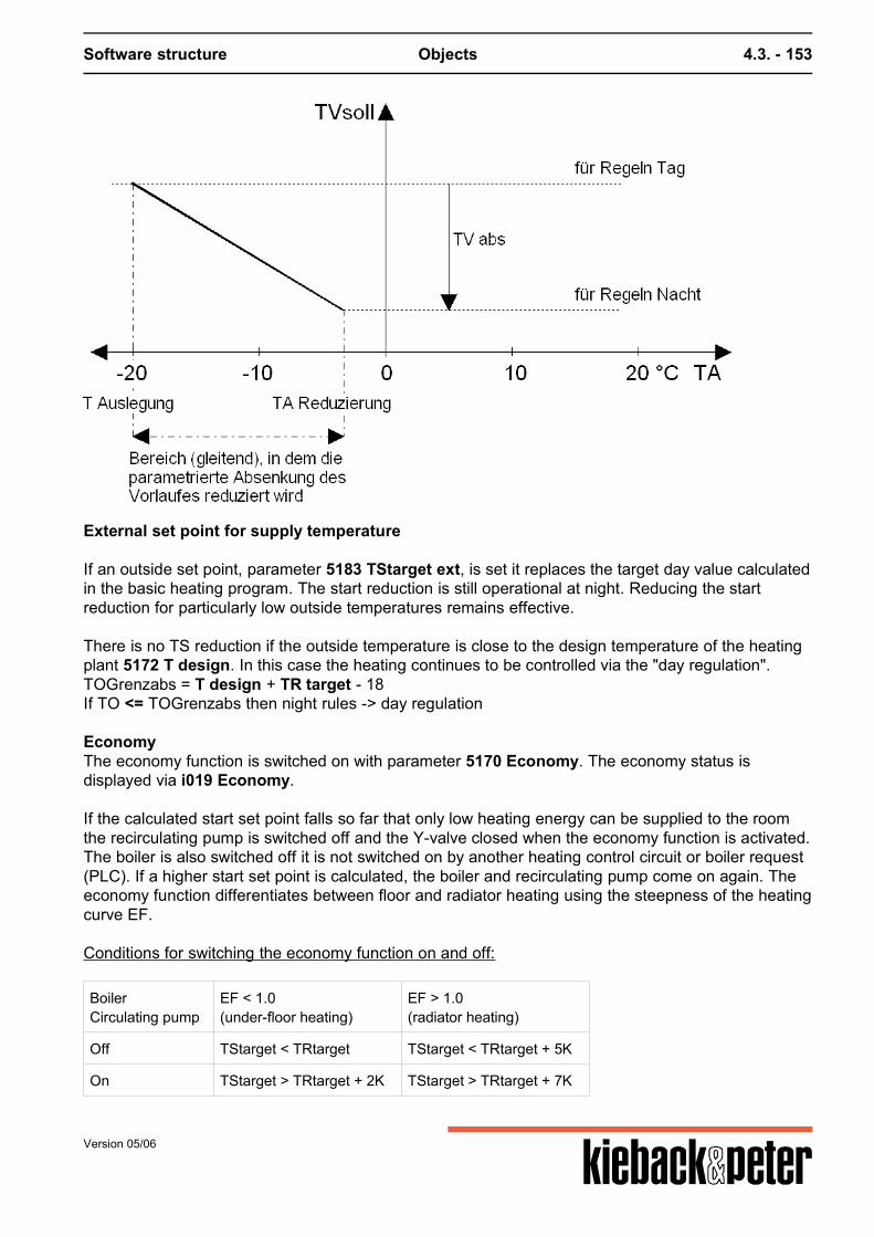
Software structure Objects 4.3. - 153
External set point for supply temperature If an outside set point, parameter 5183 TStarget ext, is set it replaces the target day value calculatedin the basic heating program. The start reduction is still operational at night. Reducing the startreduction for particularly low outside temperatures remains effective.
There is no TS reduction if the outside temperature is close to the design temperature of the heatingplant 5172 T design. In this case the heating continues to be controlled via the "day regulation".TOGrenzabs = T design + TR target - 18If TO <= TOGrenzabs then night rules -> day regulation
EconomyThe economy function is switched on with parameter 5170 Economy. The economy status isdisplayed via i019 Economy.
If the calculated start set point falls so far that only low heating energy can be supplied to the roomthe recirculating pump is switched off and the Y-valve closed when the economy function is activated.The boiler is also switched off it is not switched on by another heating control circuit or boiler request(PLC). If a higher start set point is calculated, the boiler and recirculating pump come on again. Theeconomy function differentiates between floor and radiator heating using the steepness of the heatingcurve EF. Conditions for switching the economy function on and off:
BoilerCirculating pump
EF < 1.0(under-floor heating)
EF > 1.0(radiator heating)
Off TStarget < TRtarget TStarget < TRtarget + 5K
On TStarget > TRtarget + 2K TStarget > TRtarget + 7K
Version 05/06
Software structure Objects 4.3. - 154
If the DDC software object S318 room correction or S300 optimize heating is installed and active thetarget room value TRtarget is set in this DDC sub-menu (TRtarget = MIN(TR target; source roomtemperature). Otherwise the economy function works with a fixed TRtarget = 20°C.
Frost protection
The frost protection function is switched on with parameter 5171 frost protection.It ensures that the recirculating pump does not switch off outside regular operation at an outsidetemperature < 3°C. This prevents the heating plant from freezing.The recirculating pump is only switched off when the outside temperature exceeds 6°C.
Pump blocking protection
The "pump blocking protection" is now implemented by hardware objects.
Set point remote control, correction, switching For active set point switching by software object S313 set point switching the set points are notswitched for day regulation and night rules. Only the set point stipulated by the set point switching isoperational. The current set point is calculated with the following priority:
Priority Function
Highest S313 Set point switch 1-4
S316 Set point remote control
S315 Set point correction
lowest S239 Basic program heating
Parameters
No. name of parameter parameter typ min max init unit
5000 ZustandState
actual valuemultistate
-- 10 0 value,text0,Off1,Pre-lowering2,Lowering3,Interim heating4,Heating-up5,Previous6,Regulations day7,Regulations night8,Economy9,Standby
Version 05/06
Software structure Objects 4.3. - 155
No. name of parameter parameter typ min max init unit
5102 Q RegSource controlled variable
actual valuedeletablefloat
-infinity +infinity deleted C
5103 Q TASource TA
actual valuedeletablefloat
-infinity +infinity deleted C
5105 xwXW
actual valuefloat
-infinity +infinity 0 K
5106 tNtN
set point deletableinteger
1 99 3 min
5115 Q_NState N
actual valuedeletabletext
-- -- deleted --
5120 XPY1XPY1
set pointfloat
0,5 999,9 50 K
5125 DVorhalt
set point deletableinteger
1 299 deleted s
5128 xwhxwh
set pointfloat
0 50 0 K
5141 Y1minY1 min
set pointfloat
0 100 0 %
5145 Y1maxY1 max
set pointfloat
0 100 100 %
5151 TVSaktTVSoll current
actual valuefloat
-infinity +infinity 0 C
5152 RegNachRegulate with TA
set pointboolean
-- -- 0 --
5153 TAvzTAvz
set pointfloat
-infinity +infinity 0 C
5155 EFEF
set pointfloat
0 10 1,5 --
5156 KHKH
set pointinteger
-100 100 0 K
5160 TARedTA Reduction
set point deletableinteger
-50 30 deleted C
5165 TVminTV min
set pointinteger
0 999 20 C
5166 TVmaxTV max
set pointinteger
0 999 95 C
Version 05/06
Software structure Objects 4.3. - 156
No. name of parameter parameter typ min max init unit
5167 TVabsTV abs
set pointinteger
-999 0 -12 K
5168 TAvzTime constant TAvz
set pointinteger
1 99 24 h
5169 TAmTA middle
actual valuefloat
-infinity +infinity 0 C
5170 EcoEconomy
set pointboolean
-- -- 0 --
5172 AuslegT Configuration
set pointinteger
-50 0 -12 C
5173 YYH1
actual valuefloat
0 100 0 %
5175 QFernSource remote control
actual valuemultistate
-- 4 0 value,text9,Auto1,Source remote day35,Source remote night0,Source remote OFF
5182 Pu tPumps return flow
set pointinteger
0 30 20 min
5183 TVSoll eTV Set ext
actual valuedeletablefloat
-infinity +infinity deleted C
7801 h Y1Manual influence Y1
set point deletablefloat
0 100 deleted %
i004 TagRegulate day
actual valueboolean
-- -- 0 --
i005 NachtRegulate night
actual valueboolean
-- -- 0 --
i006 OptOptimize
actual valueboolean
-- -- 0 --
i007 AufhHeating
actual valueboolean
-- -- 0 --
i009 AusControl condition AUS
actual valueboolean
-- -- 0 --
i010 ZHeizIntermediate heating
actual valueboolean
-- -- 0 --
i019 EcoEconomy
actual valueboolean
-- -- 0 --
Version 05/06
Software structure Objects 4.3. - 157
No. name of parameter parameter typ min max init unit
i020 XP UXP Changeover
actual valueboolean
-- -- 0 --
Z ZZ-contacts
actual valuemultistate
-- 5 4 value,text1,Z1 Day35,Z2 Night36,Z3 Heating up0,Z4 Off9,Automatic
* Nr. Beschreibung
1) H01 Bem: RPG-Index und "instanziiert-Bit" Red. 25.7.03 nach Fehlermeldung Sti.
2) State Gibt den Zustand des Heizautomaten wieder. 0 - Aus1 - Vorabsenken2 - Absenken3 - Zwischenheizen4 - Aufheizen5 - Vorein6 - Regeln Tag7 - Regeln Nacht8 - Economy9 - Stand By
What is missing:- better image file for heating curve, original is a Word graphic- TO reduction, T design - image file, original is a Word graphic
Version 05/06
Software structure Objects 4.3. - 158
4.3.2.10.1. Graphical summaries
TStarget calculation
Version 05/06
Software structure Objects 4.3. - 159
The controller
Version 05/06
Software structure Objects 4.3. - 160
The statuses
Version 05/06
Software structure Objects 4.3. - 161
4.3.2.10.2. S300 Optimization
Activation
Sub-function of basic heating program can be set once
Can be switched on-off via 5380 Q EA Optimization if not defined, ON
Condition A usage time program (schedule object S117) must beassigned to the basic program.
Function summary
The DDC software object S300 Optimization (heating) has the function of controlling a heating plantsuch that at the start of the usage time the desired room temperature is reached and can fall directlyat the end of the usage time. For this the parameters that represent the temperature behavior of the building are set, temperaturesmeasured and calculations undertaken. These calculations include the responses of the previouscontrol and management processes, i. e. it is adapted. Times are calculated for switching the heating on in order to achieve the desired room temperature atthe start of the usage time, or to lower the heating.
Function description
With the DDC software object the minimum heating time to achieve the target room value at the startof use is calculated. In the heating-up operation the building is heated with the maximum supplytemperature. If the room temperature reaches the target room value of 5180 TRtarget operation isswitched from "warm up" to "day regulation". Using 5560 TAUup the correct heating start time iscalculated. The 5560 TAUup and 5561 TAUdown parameters are adapted as per the localenvironment. The operation of the sub-menu can be switched ON or OFF via the binary source 5380 Q EAOptimization.
Version 05/06
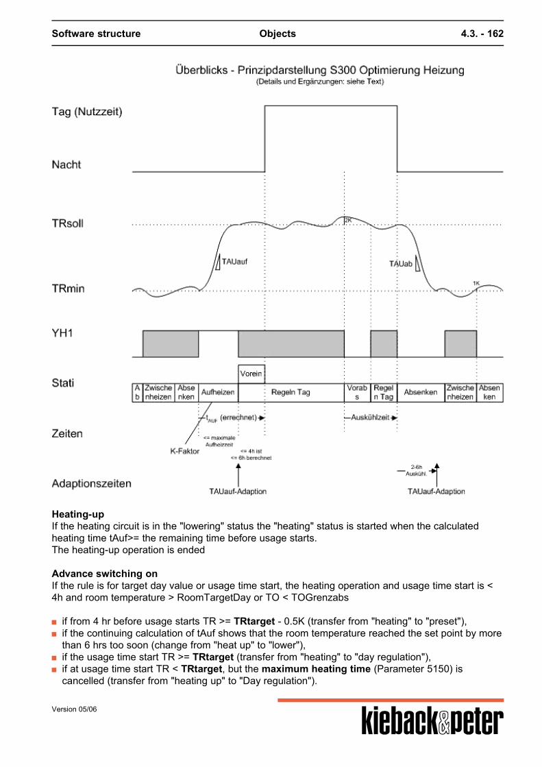
Software structure Objects 4.3. - 162
Heating-upIf the heating circuit is in the "lowering" status the "heating" status is started when the calculatedheating time tAuf>= the remaining time before usage starts.The heating-up operation is ended
Advance switching onIf the rule is for target day value or usage time start, the heating operation and usage time start is <4h and room temperature > RoomTargetDay or TO < TOGrenzabs
if from 4 hr before usage starts TR >= TRtarget - 0.5K (transfer from "heating" to "preset"), if the continuing calculation of tAuf shows that the room temperature reached the set point by more
than 6 hrs too soon (change from "heat up" to "lower"), if the usage time start TR >= TRtarget (transfer from "heating" to "day regulation"), if at usage time start TR < TRtarget, but the maximum heating time (Parameter 5150) is
cancelled (transfer from "heating up" to "Day regulation").
Version 05/06
Software structure Objects 4.3. - 163
Reduction operationThe relevant heating circuit moves to the "lower" status if
end of usage is reached (Schedule output = night) or advance lowering is calculated (presets).
Advance loweringIn order to save energy the heating circuit can be changed to lowering operation if there is over-heating as a result of third-party heating or the room's storage behavior even before the end of theusage time.The calculation as to whether early switching off is possible is activated when: TR > TRtarget +2K.Advance switching off takes place if the "Cooling time >= the remaining usage time". The coolingtime is the period in which the room cools to the TRtargettemperature.The heating switches on again (Day regulation) if TR < TRtarget. The advance lowering can be permitted or prohibited using the 5565 Advlow parameter. Interim heatingInterim heating is used in lowering operation if the temperature falls below the lowering temperature5181 TRmin.The intermediate heating status is quitted again,
if TR >= TRmin + 1 K (transfer from "intermediate heating" after "falling"), if TR >= TRmin + 3 K, if the time to the next usage time is still more than 12 hours AND the difference TRtarget -
TRminis >= 6 K (transfer from "intermediate heating" and "lowering"), if TO <= T design + TRtarget - 18 K (transfer from "intermediate heating" to "Heating"), if the time span to the next usage time is lower than the calculated heating time (transfer from
"intermediate heating" to "heating").
TAUup-AdaptionThe parameter 5560 TAUup describes the temperature increase (in K per hour) when heating thebuilding. TAUup is a relatively long-term average value for the building physics facts (buildingconstants) and is stated in the basic setting at 0.420 K/h. The TAUup-Adaption occurs at the end of the heating period. (time of transfer from "heating" to "dayregulation", "preset" or a return to "lowering" as a result of exceeding the TRtarget).Recalculating the TAUup only occurs if the actual heating time is larger than 40 and the temperatureincrease in the room is at least 0.5 K. 40 % of the newly calculated TAUup value flows into thecalculation: TAUup = 0.6 * TAUupOLD + 0.4 * TAUupNEW Heating time = (TRtarget – Room temperature) / TAUup + idle time TAUupNEW = (Room temperature heating - Room temperature heating start) / (heating end - heatingstart) When starting up a different basic time setting can be set.The TAUup-Adaption can be permitted or prohibited with the 5564 TAUup-Adapt parameter
TAUdown-AdaptionThe parameter 5561 TAUdown describes the temperature decrease (in K per hour) when cooling the
Version 05/06
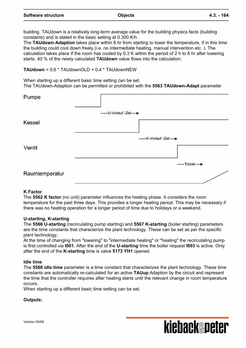
Software structure Objects 4.3. - 164
building. TAUdown is a relatively long-term average value for the building physics facts (buildingconstants) and is stated in the basic setting at 0.300 K/h.The TAUdown-Adaption takes place within 6 hr from starting to lower the temperature, if in this timethe building could cool down freely (i.e. no intermediate heating, manual intervention etc. ). Thecalculation takes place if the room has cooled by 0.3 K within the period of 2 h to 6 hr after loweringstarts. 40 % of the newly calculated TAUdown value flows into the calculation: TAUdown = 0,6 * TAUdownOLD + 0,4 * TAUdownNEW When starting up a different basic time setting can be set.The TAUdown-Adaption can be permitted or prohibited with the 5563 TAUdown-Adapt parameter
K FactorThe 5562 K factor (no unit) parameter influences the heating phase. It considers the roomtemperature for the past three days. This provides a longer heating period. This may be necessary ifthere was no heating operation for a longer period of time due to holidays or a weekend. U-starting, K-startingThe 5566 U-starting (recirculating pump starting) and 5567 K-starting (boiler starting) parametersare the time constants that characterize the plant technology. These can be set as per the specificplant technology.At the time of changing from "lowering" to "intermediate heating" or "heating" the recirculating pumpis first controlled via I001. After the end of the U-starting time the boiler request I003 is active. Onlyafter the end of the K-starting time is valve 5173 YH1 opened. Idle timeThe 5568 idle time parameter is a time constant that characterizes the plant technology. These timeconstants are automatically re-calculated for an active TAUup Adaption by the circuit and representthe time that the controller requires after heating starts until the relevant change in room temperatureoccurs.When starting up a different basic time setting can be set. Outputs:
Version 05/06
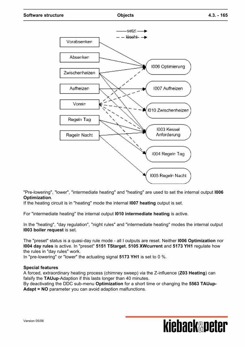
Software structure Objects 4.3. - 165
"Pre-lowering", "lower", "intermediate heating" and "heating" are used to set the internal output I006Optimization.If the heating circuit is in "heating" mode the internal I007 heating output is set.
For "intermediate heating" the internal output I010 intermediate heating is active.
In the "heating", "day regulation", "night rules" and "intermediate heating" modes the internal outputI003 boiler request is set. The "preset" status is a quasi-day rule mode - all I outputs are reset. Neither I006 Optimization norI004 day rules is active. In "preset" 5151 TStarget, 5105 XWcurrent and 5173 YH1 regulate howthe rules in "day rules" work.In "pre-lowering" or "lower" the actuating signal 5173 YH1 is set to 0 %. Special featuresA forced, extraordinary heating process (chimney sweep) via the Z-influence (Z03 Heating) canfalsify the TAUup-Adaption if this lasts longer than 40 minutes.By deactivating the DDC sub-menu Optimization for a short time or changing the 5563 TAUup-Adapt = NO parameter you can avoid adaption malfunctions.
Version 05/06
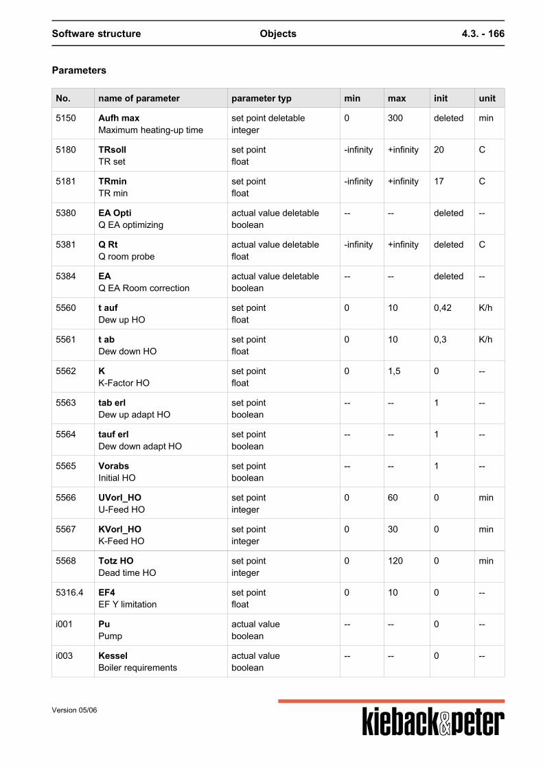
Software structure Objects 4.3. - 166
Parameters
No. name of parameter parameter typ min max init unit
5150 Aufh maxMaximum heating-up time
set point deletableinteger
0 300 deleted min
5180 TRsollTR set
set pointfloat
-infinity +infinity 20 C
5181 TRminTR min
set pointfloat
-infinity +infinity 17 C
5380 EA OptiQ EA optimizing
actual value deletableboolean
-- -- deleted --
5381 Q RtQ room probe
actual value deletablefloat
-infinity +infinity deleted C
5384 EAQ EA Room correction
actual value deletableboolean
-- -- deleted --
5560 t aufDew up HO
set pointfloat
0 10 0,42 K/h
5561 t abDew down HO
set pointfloat
0 10 0,3 K/h
5562 KK-Factor HO
set pointfloat
0 1,5 0 --
5563 tab erlDew up adapt HO
set pointboolean
-- -- 1 --
5564 tauf erlDew down adapt HO
set pointboolean
-- -- 1 --
5565 VorabsInitial HO
set pointboolean
-- -- 1 --
5566 UVorl_HOU-Feed HO
set pointinteger
0 60 0 min
5567 KVorl_HOK-Feed HO
set pointinteger
0 30 0 min
5568 Totz HODead time HO
set pointinteger
0 120 0 min
5316.4 EF4EF Y limitation
set pointfloat
0 10 0 --
i001 PuPump
actual valueboolean
-- -- 0 --
i003 KesselBoiler requirements
actual valueboolean
-- -- 0 --
Version 05/06

Software structure Objects 4.3. - 167
what is missing: good process diagrams, times
Version 05/06
Software structure Objects 4.3. - 168
4.3.2.10.3. S301 Y limitation
Activation
Sub-function of each heating and ventilation basic program 0 ... can be set 4 x
Can be switched on-off via 5319 Q EA Y limitation if not linked, ON
Function summary
The DDC software object S301 Y limitation influences the min or max limits of the Y outputs for theDDC control circuits (basic program).A difference is to be made between two influence options that can jointly affect the basic function ofthe DDC control circuits:
1. Depending on a limitation factor the Y outputs Y-min or Y-max set in the basic program for theDDC control circuits are altered. The influence on the Y-min or Y-max occurs after the limitationfactor reaches a particular limiting value.- For the MAX limit the limiting value must have exceeded the limiting value.- for the MIN limit the limitation factor must be below the limiting value so as to influence thesetting range of the Y-outputs.- By inverting the Y-limit YES / NO the direction of influencing the Y-setting range is stipulated.
2. In addition to the functions stated in 1 the limiting value of the limitation factor can itself glide in aparticular range. I.e. depending on the outside temperature (basic program) the limiting value ofthe limitation factor is also changed.
Function description
Re 1: The limitation factor is set in parameter 5311 source Y-limitation. Any DDC4000 system analogvalue can be set. The Y-limitation influences the Y-output parameterized on parameter 5310 Y-limit. on.
The DDC sub.menu Y-limit can be installed and set repeatedly for a DDC control circuit. If several Y-limitation DDC sub-menus work on the same Y output, the min and max limits calculated for eachDDC software object are added.
For the basic PID program you have to choose between the 4 potential Y outputs.For the basic heating program the Y limit always works on the heating control for a Y output. Parameter 5312 YB-limiting value sets the value from which the Y limit should act on the Y outputsetting range. Parameter 5313 YB limitation stipulateswhether a MAX limitation, i.e. exceeding the limiting value (image 3, image 4)o ra MIN limitation, i.e. going below the limiting value (image 1, image 2)
Version 05/06
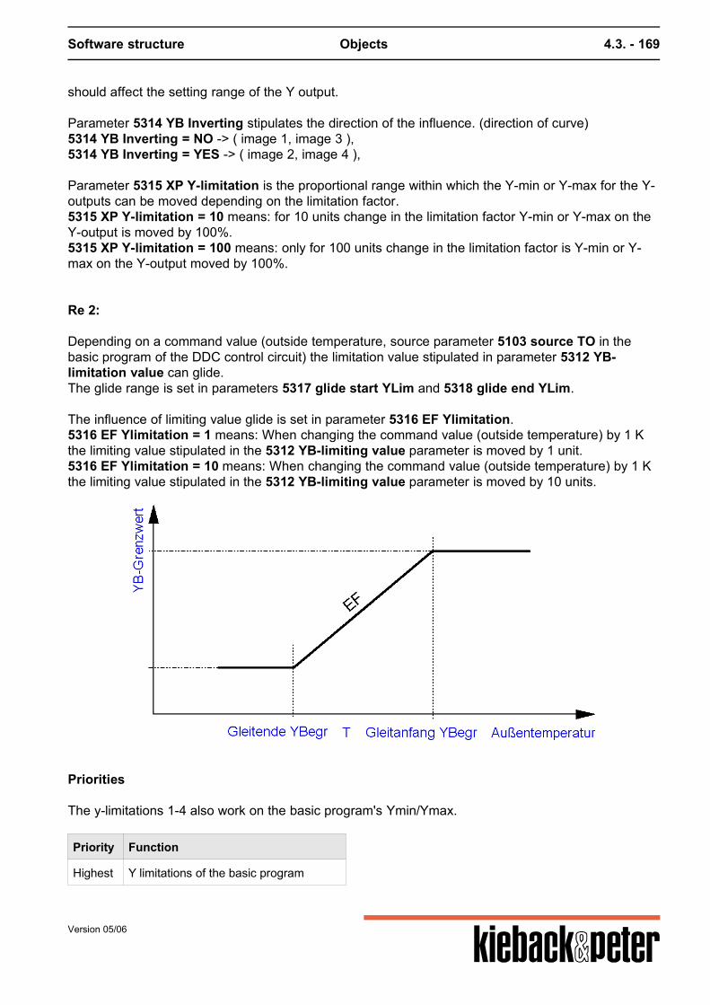
Software structure Objects 4.3. - 169
should affect the setting range of the Y output. Parameter 5314 YB Inverting stipulates the direction of the influence. (direction of curve)5314 YB Inverting = NO -> ( image 1, image 3 ),5314 YB Inverting = YES -> ( image 2, image 4 ), Parameter 5315 XP Y-limitation is the proportional range within which the Y-min or Y-max for the Y-outputs can be moved depending on the limitation factor.5315 XP Y-limitation = 10 means: for 10 units change in the limitation factor Y-min or Y-max on theY-output is moved by 100%.5315 XP Y-limitation = 100 means: only for 100 units change in the limitation factor is Y-min or Y-max on the Y-output moved by 100%. Re 2: Depending on a command value (outside temperature, source parameter 5103 source TO in thebasic program of the DDC control circuit) the limitation value stipulated in parameter 5312 YB-limitation value can glide.The glide range is set in parameters 5317 glide start YLim and 5318 glide end YLim. The influence of limiting value glide is set in parameter 5316 EF Ylimitation.5316 EF Ylimitation = 1 means: When changing the command value (outside temperature) by 1 Kthe limiting value stipulated in the 5312 YB-limiting value parameter is moved by 1 unit.5316 EF Ylimitation = 10 means: When changing the command value (outside temperature) by 1 Kthe limiting value stipulated in the 5312 YB-limiting value parameter is moved by 10 units.
Priorities
The y-limitations 1-4 also work on the basic program's Ymin/Ymax.
Priority Function
Highest Y limitations of the basic program
Version 05/06
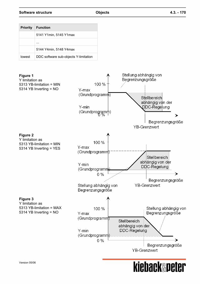
Software structure Objects 4.3. - 170
Priority Function
5141 Y1min, 5145 Y1max
...
5144 Y4min, 5148 Y4max
lowest DDC software sub-objects Y-limitation
Figure 1Y limitation as5313 YB-limitation = MIN5314 YB Inverting = NO
Figure 2Y limitation as5313 YB-limitation = MIN5314 YB Inverting = YES
Figure 3Y limitation as5313 YB-limitation = MAX5314 YB Inverting = NO
Version 05/06
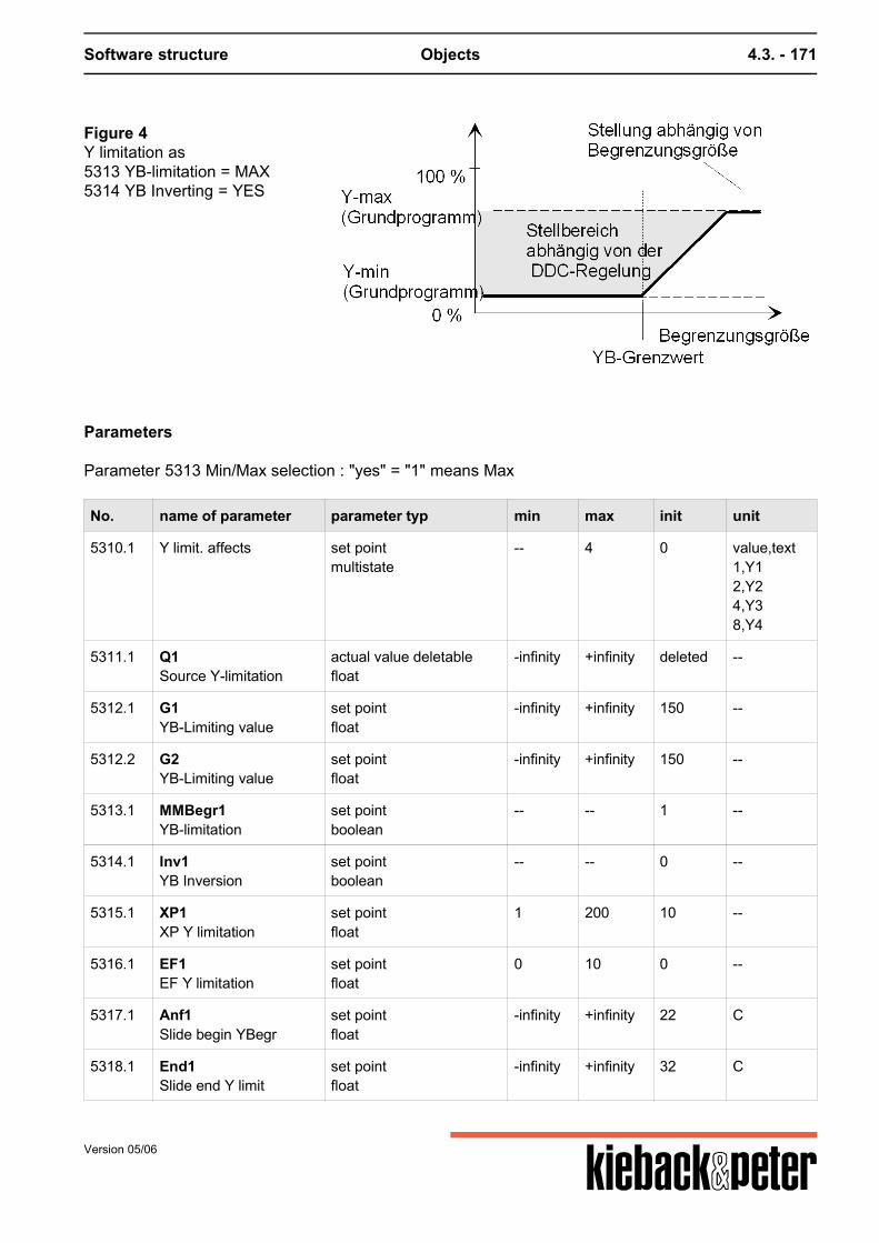
Software structure Objects 4.3. - 171
Figure 4Y limitation as5313 YB-limitation = MAX5314 YB Inverting = YES
Parameters
Parameter 5313 Min/Max selection : "yes" = "1" means Max
No. name of parameter parameter typ min max init unit
5310.1 Y limit. affects set pointmultistate
-- 4 0 value,text1,Y12,Y24,Y38,Y4
5311.1 Q1Source Y-limitation
actual value deletablefloat
-infinity +infinity deleted --
5312.1 G1YB-Limiting value
set pointfloat
-infinity +infinity 150 --
5312.2 G2YB-Limiting value
set pointfloat
-infinity +infinity 150 --
5313.1 MMBegr1YB-limitation
set pointboolean
-- -- 1 --
5314.1 Inv1YB Inversion
set pointboolean
-- -- 0 --
5315.1 XP1XP Y limitation
set pointfloat
1 200 10 --
5316.1 EF1EF Y limitation
set pointfloat
0 10 0 --
5317.1 Anf1Slide begin YBegr
set pointfloat
-infinity +infinity 22 C
5318.1 End1Slide end Y limit
set pointfloat
-infinity +infinity 32 C
Version 05/06
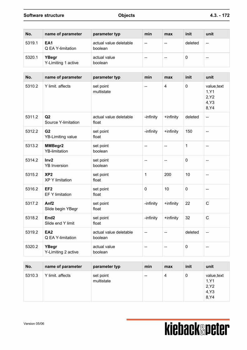
Software structure Objects 4.3. - 172
No. name of parameter parameter typ min max init unit
5319.1 EA1Q EA Y-limitation
actual value deletableboolean
-- -- deleted --
5320.1 YBegrY-Limiting 1 active
actual valueboolean
-- -- 0 --
No. name of parameter parameter typ min max init unit
5310.2 Y limit. affects set pointmultistate
-- 4 0 value,text1,Y12,Y24,Y38,Y4
5311.2 Q2Source Y-limitation
actual value deletablefloat
-infinity +infinity deleted --
5312.2 G2YB-Limiting value
set pointfloat
-infinity +infinity 150 --
5313.2 MMBegr2YB-limitation
set pointboolean
-- -- 1 --
5314.2 Inv2YB Inversion
set pointboolean
-- -- 0 --
5315.2 XP2XP Y limitation
set pointfloat
1 200 10 --
5316.2 EF2EF Y limitation
set pointfloat
0 10 0 --
5317.2 Anf2Slide begin YBegr
set pointfloat
-infinity +infinity 22 C
5318.2 End2Slide end Y limit
set pointfloat
-infinity +infinity 32 C
5319.2 EA2Q EA Y-limitation
actual value deletableboolean
-- -- deleted --
5320.2 YBegrY-Limiting 2 active
actual valueboolean
-- -- 0 --
No. name of parameter parameter typ min max init unit
5310.3 Y limit. affects set pointmultistate
-- 4 0 value,text1,Y12,Y24,Y38,Y4
Version 05/06

Software structure Objects 4.3. - 173
No. name of parameter parameter typ min max init unit
5311.3 Q3Source Y-limitation
actual value deletablefloat
-infinity +infinity deleted --
5312.3 G3YB-Limiting value
set pointfloat
-infinity +infinity 150 --
5313.3 MMBegr3YB-limitation
set pointboolean
-- -- 1 --
5314.3 Inv3YB Inversion
set pointboolean
-- -- 0 --
5315.3 XP3XP Y limitation
set pointfloat
1 200 10 --
5316.3 EF3EF Y limitation
set pointfloat
0 10 0 --
5317.3 Anf3Slide begin YBegr
set pointfloat
-infinity +infinity 22 C
5318.3 End3Slide end Y limit
set pointfloat
-infinity +infinity 32 C
5319.3 EA3Q EA Y-limitation
actual value deletableboolean
-- -- deleted --
5320.3 YBegrY-Limiting 3 active
actual valueboolean
-- -- 0 --
No. name of parameter parameter typ min max init unit
5310.4 Y limit. affects set pointmultistate
-- 4 0 value,text1,Y12,Y24,Y38,Y4
5311.4 Q4Source Y-limitation
actual value deletablefloat
-infinity +infinity deleted --
5312.4 G4YB-Limiting value
set pointfloat
-infinity +infinity 150 --
5313.4 MMBegr4YB-limitation
set pointboolean
-- -- 1 --
5314.4 Inv4YB Inversion
set pointboolean
-- -- 0 --
5315.4 XP4XP Y limitation
set pointfloat
1 200 10 --
5316.4 EF4EF Y limitation
set pointfloat
0 10 0 --
Version 05/06

Software structure Objects 4.3. - 174
No. name of parameter parameter typ min max init unit
5317.4 Anf4Slide begin YBegr
set pointfloat
-infinity +infinity 22 C
5318.4 End4Slide end Y limit
set pointfloat
-infinity +infinity 32 C
5319.4 EA4Q EA Y-limitation
actual value deletableboolean
-- -- deleted --
5320.4 YBegrY-Limiting 4 active
actual valueboolean
-- -- 0 --
Version 05/06
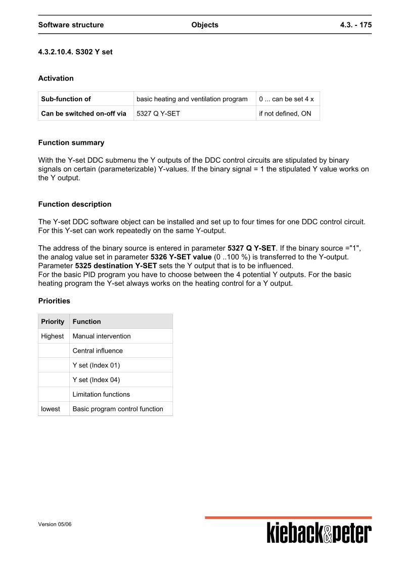
Software structure Objects 4.3. - 175
4.3.2.10.4. S302 Y set
Activation
Sub-function of basic heating and ventilation program 0 ... can be set 4 x
Can be switched on-off via 5327 Q Y-SET if not defined, ON
Function summary
With the Y-set DDC submenu the Y outputs of the DDC control circuits are stipulated by binarysignals on certain (parameterizable) Y-values. If the binary signal = 1 the stipulated Y value works onthe Y output.
Function description
The Y-set DDC software object can be installed and set up to four times for one DDC control circuit.For this Y-set can work repeatedly on the same Y-output. The address of the binary source is entered in parameter 5327 Q Y-SET. If the binary source ="1",the analog value set in parameter 5326 Y-SET value (0 ..100 %) is transferred to the Y-output.Parameter 5325 destination Y-SET sets the Y output that is to be influenced.For the basic PID program you have to choose between the 4 potential Y outputs. For the basicheating program the Y-set always works on the heating control for a Y output. Priorities
Priority Function
Highest Manual intervention
Central influence
Y set (Index 01)
Y set (Index 04)
Limitation functions
lowest Basic program control function
Version 05/06

Software structure Objects 4.3. - 176
Parameters
Parameter 5325.x only applies if used in the GP PID!
No. name of parameter parameter typ min max init unit
5325.1 Ziel1Destination Y set
set pointmultistate
-- 4 0 value,text1,Y12,Y24,Y38,Y4
5326.1 Wert1Y set value
set pointfloat
0 100 0 %
5327.1 Q1Q Y fix
actual value deletableboolean
-- -- deleted --
No. name of parameter parameter typ min max init unit
5325.2 Ziel2Destination Y set
set pointmultistate
-- 4 0 value,text1,Y12,Y24,Y38,Y4
5326.2 Wert2Y set value
set pointfloat
0 100 0 %
5327.2 Q2Q Y fix
actual value deletableboolean
-- -- deleted --
Version 05/06
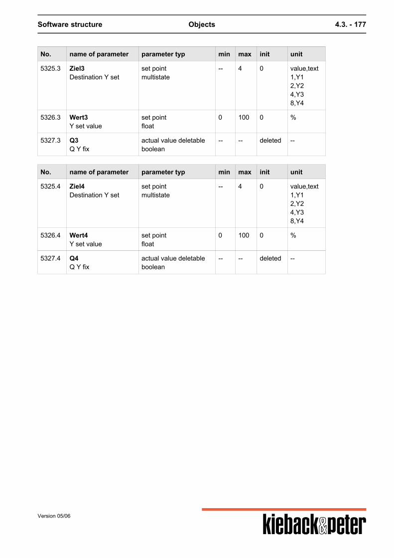
Software structure Objects 4.3. - 177
No. name of parameter parameter typ min max init unit
5325.3 Ziel3Destination Y set
set pointmultistate
-- 4 0 value,text1,Y12,Y24,Y38,Y4
5326.3 Wert3Y set value
set pointfloat
0 100 0 %
5327.3 Q3Q Y fix
actual value deletableboolean
-- -- deleted --
No. name of parameter parameter typ min max init unit
5325.4 Ziel4Destination Y set
set pointmultistate
-- 4 0 value,text1,Y12,Y24,Y38,Y4
5326.4 Wert4Y set value
set pointfloat
0 100 0 %
5327.4 Q4Q Y fix
actual value deletableboolean
-- -- deleted --
Version 05/06
Software structure Objects 4.3. - 178
4.3.2.10.5. S312 Limitation
Activation
Sub-function of basic heating and ventilation program 0 ... can be set 2 x
Can be switched on-off via 5279 Q EA limitation if not defined, ON
Function summary
The DDC control function of the main control circuit is restricted using DDC software object limitation.The limitation is required for example:
for keeping the supply air temperature in ventilation controls in comfortable limits to curb the supply temperature in heating controls before reaching technological limiting values.
A max or min limit is possible in line with the requests. The max or min limits may glide in line with a command value. E.g. if for ventilation controls, besidelifting the room´s set point depending on the outside temperature, concurrently min limit of the supplyair is lifted.
Function description
In the DDC software object limitation the selected limitation sensor in the source parameter5270 Q limitation sensor is set. The limitation value is set with parameter5271 limitation value. Parameter 5272 limitation sets whether this is a max or a min limiting value. The limitation works in the following 2 phases: a) The value of the limitation sensor nears the max or min limitation value.b) The value of the limitation sensor is higher or lower than the max or min limitation value. Re a) the limitation function is adopted gliding. The variance of the limitation sensor to the limitationvalue is compared with the main control variance of the basic program. Depending on the relevantcontrol variance control is still made with the main control circuit XP. Re b) if the set Max limitation value is exceeded or the number falls below the min limitation value allXPs on the control circuit are replaced by 5273 XPlimitation in order control the limitation valueinfringement as quickly as possible. This control status is indicated by switching the internal contactV10 limitation and I020 XP switching from "0" to "1". Limiting value glide can occur for both the min. and max limiting values using command value sourceparameter 5275 command value limit. The range in which the min and max limits should glide is stipulated by parameters 5277 glide startlimit and 5278 glide end limit. The influence of gliding is set by parameter 5276 EFg. If 5276 EFg =0, glide does not occur. If inverting is set winter compensation takes place, i.e. the limiting value is raised if the command
Version 05/06
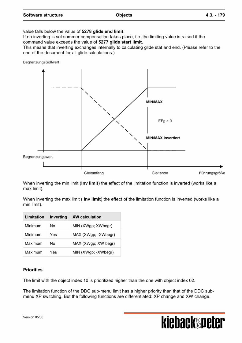
Software structure Objects 4.3. - 179
value falls below the value of 5278 glide end limit.If no inverting is set summer compensation takes place, i.e. the limiting value is raised if thecommand value exceeds the value of 5277 glide start limit.This means that inverting exchanges internally to calculating glide stat and end. (Please refer to theend of the document for all glide calculations.)
When inverting the min limit (Inv limit) the effect of the limitation function is inverted (works like amax limit). When inverting the max limit ( Inv limit) the effect of the limitation function is inverted (works like amin limit).
Limitation Inverting XW calculation
Minimum No MIN (XWgp; XWbegr)
Minimum Yes MAX (XWgp; -XWbegr)
Maximum No MAX (XWgp; XW begr)
Maximum Yes MIN (XWgp; -XWbegr)
Priorities
The limit with the object index 10 is prioritized higher than the one with object index 02. The limitation function of the DDC sub-menu limit has a higher priority than that of the DDC sub-menu XP switching. But the following functions are differentiated: XP change and XW change.
Version 05/06
Software structure Objects 4.3. - 180
Priorities of the limitation function a) (change to the current control variance):
Priority Function
Highest S312.1 Limitation 1
S303 Cascade (only PID)
lowest S312.2 Limitation 2
The current control variance is determined as follows:
1. XWcurrent = Limitation 2 (XWbasic program, XWlimitation2)2. XWcurrent = cascade (XWcurrent, XWcascade) (only PID)3. XWcurrent = Limitation 1 (XWcurrent, XWlimitation1)
Priorities of the limitation function b) (change to the XP range):
Priority Function
Highest S312.1 Limitation 1
S312.2 Limitation 2
lowest S317 XP conversion
Parameters
No. name of parameter parameter typ min max init unit
5270.1 QQ limitation sensor
actual value deletablefloat
-infinity +infinity deleted --
5271.1 Limitation value set pointfloat
-infinity +infinity 150 --
5272.1 Limitation set pointmultistate
-- 2 1 value,text0,Minimum1,Maximum
5273.1 XP1XP limitation
set pointfloat
0,5 200 10 --
5274.1 invInv. limitation
set pointboolean
-- -- 0 --
5275.1 Q_FgLead size limit
actual value deletablefloat
-infinity +infinity deleted --
5276.1 EFgEFg
set pointfloat
-10 10 0 --
Version 05/06
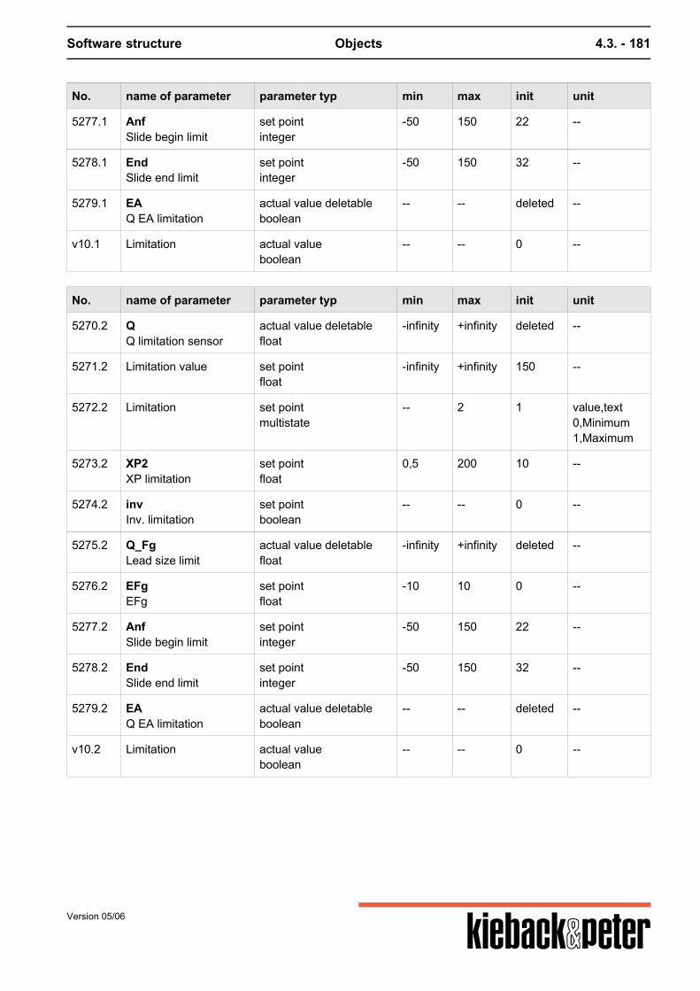
Software structure Objects 4.3. - 181
No. name of parameter parameter typ min max init unit
5277.1 AnfSlide begin limit
set pointinteger
-50 150 22 --
5278.1 EndSlide end limit
set pointinteger
-50 150 32 --
5279.1 EAQ EA limitation
actual value deletableboolean
-- -- deleted --
v10.1 Limitation actual valueboolean
-- -- 0 --
No. name of parameter parameter typ min max init unit
5270.2 QQ limitation sensor
actual value deletablefloat
-infinity +infinity deleted --
5271.2 Limitation value set pointfloat
-infinity +infinity 150 --
5272.2 Limitation set pointmultistate
-- 2 1 value,text0,Minimum1,Maximum
5273.2 XP2XP limitation
set pointfloat
0,5 200 10 --
5274.2 invInv. limitation
set pointboolean
-- -- 0 --
5275.2 Q_FgLead size limit
actual value deletablefloat
-infinity +infinity deleted --
5276.2 EFgEFg
set pointfloat
-10 10 0 --
5277.2 AnfSlide begin limit
set pointinteger
-50 150 22 --
5278.2 EndSlide end limit
set pointinteger
-50 150 32 --
5279.2 EAQ EA limitation
actual value deletableboolean
-- -- deleted --
v10.2 Limitation actual valueboolean
-- -- 0 --
Version 05/06

Software structure Objects 4.3. - 182
Calculating the gliding of the target limitation value
glide start < glide end
glide end < glide start
Version 05/06
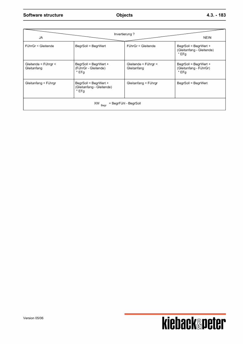
Software structure Objects 4.3. - 183
Version 05/06
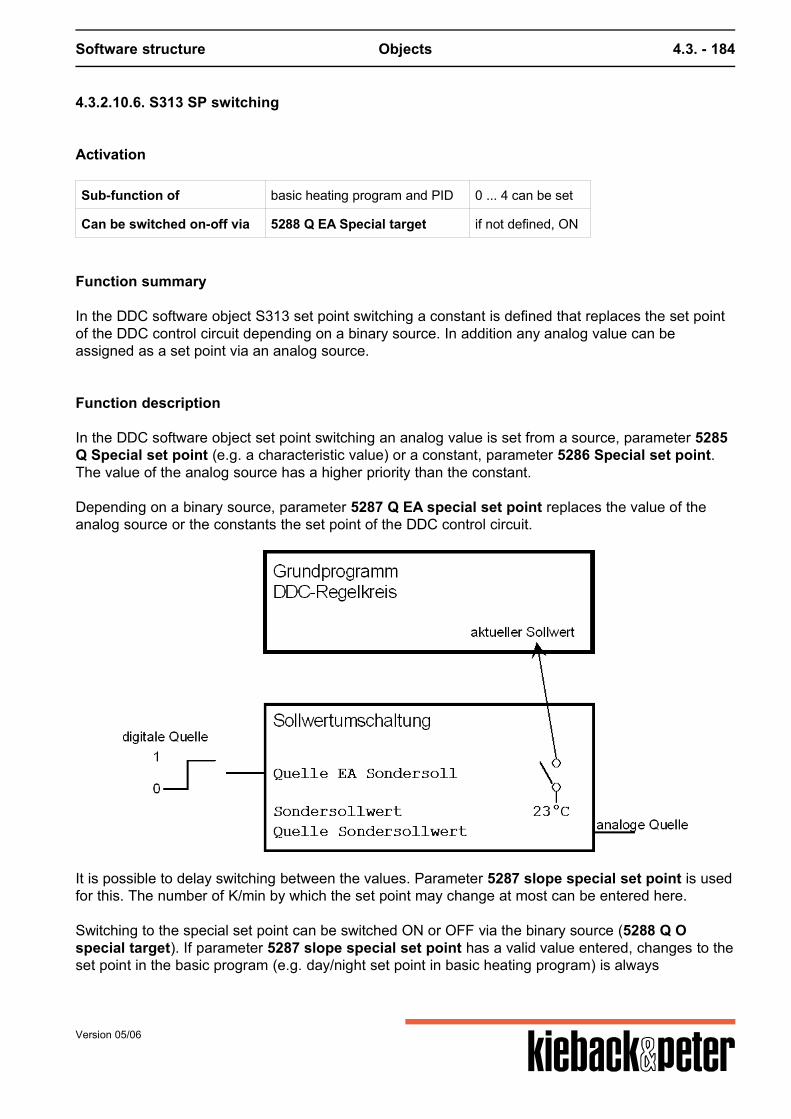
Software structure Objects 4.3. - 184
4.3.2.10.6. S313 SP switching
Activation
Sub-function of basic heating program and PID 0 ... 4 can be set
Can be switched on-off via 5288 Q EA Special target if not defined, ON
Function summary
In the DDC software object S313 set point switching a constant is defined that replaces the set pointof the DDC control circuit depending on a binary source. In addition any analog value can beassigned as a set point via an analog source.
Function description
In the DDC software object set point switching an analog value is set from a source, parameter 5285Q Special set point (e.g. a characteristic value) or a constant, parameter 5286 Special set point.The value of the analog source has a higher priority than the constant. Depending on a binary source, parameter 5287 Q EA special set point replaces the value of theanalog source or the constants the set point of the DDC control circuit.
It is possible to delay switching between the values. Parameter 5287 slope special set point is usedfor this. The number of K/min by which the set point may change at most can be entered here. Switching to the special set point can be switched ON or OFF via the binary source (5288 Q Ospecial target). If parameter 5287 slope special set point has a valid value entered, changes to theset point in the basic program (e.g. day/night set point in basic heating program) is always
Version 05/06
Software structure Objects 4.3. - 185
accompanies by a time delay for an active "Menu SPSW". The slope with the highest priority isoperational (object index 1 before 2 before 3 before 4).
Priorities
Object index 1 has the highest priority, menu index 4 has the lowest priority.
1. Set point switching 1 15313.12. Set point switching 2 15313.23. Set point switching 3 15313.34. Set point switching 4 15313.45. Set point remote control 153166. Set point correction 15315
Note
Basic heating program:In the basic heating program the set point switching replaces the calculate TStarget current from thebasic program or the target room value TR target for the set DDC sub-menu 15318 room correctionand/or 15300 optimize. Switching to a firm TS target/TR target excludes night falls. If the optimizesub-menu is active the new TR target influences intermediate heating, pre-lowering, preset, theheating up time and the adaptions. Basic PID program:In the PID basic program for active set point switching the current set point XS current is overwritten.If in addition to the basic program the DDC software object S314 set point glide also works thiscalculated XS current is overwritten.
Parameters
No. name of parameter parameter typ min max init unit
5285.1 Q-XSQ Sondersollwert
actual value deletablefloat
-50 150 deleted C
5286.1 XScustom setpoint
set pointfloat
-50 150 0 C
5287.1 K/minQ EA custom setpoint
set point deletablefloat
0,1 60 deleted K/min
5288.1 EAQ EA custom setpoint
actual value deletableboolean
-- -- deleted --
No. name of parameter parameter typ min max init unit
5285.2 Q-XSQ Sondersollwert
actual value deletablefloat
-50 150 deleted C
Version 05/06
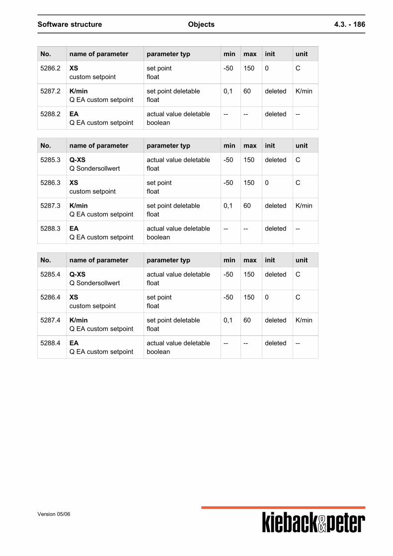
Software structure Objects 4.3. - 186
No. name of parameter parameter typ min max init unit
5286.2 XScustom setpoint
set pointfloat
-50 150 0 C
5287.2 K/minQ EA custom setpoint
set point deletablefloat
0,1 60 deleted K/min
5288.2 EAQ EA custom setpoint
actual value deletableboolean
-- -- deleted --
No. name of parameter parameter typ min max init unit
5285.3 Q-XSQ Sondersollwert
actual value deletablefloat
-50 150 deleted C
5286.3 XScustom setpoint
set pointfloat
-50 150 0 C
5287.3 K/minQ EA custom setpoint
set point deletablefloat
0,1 60 deleted K/min
5288.3 EAQ EA custom setpoint
actual value deletableboolean
-- -- deleted --
No. name of parameter parameter typ min max init unit
5285.4 Q-XSQ Sondersollwert
actual value deletablefloat
-50 150 deleted C
5286.4 XScustom setpoint
set pointfloat
-50 150 0 C
5287.4 K/minQ EA custom setpoint
set point deletablefloat
0,1 60 deleted K/min
5288.4 EAQ EA custom setpoint
actual value deletableboolean
-- -- deleted --
Version 05/06
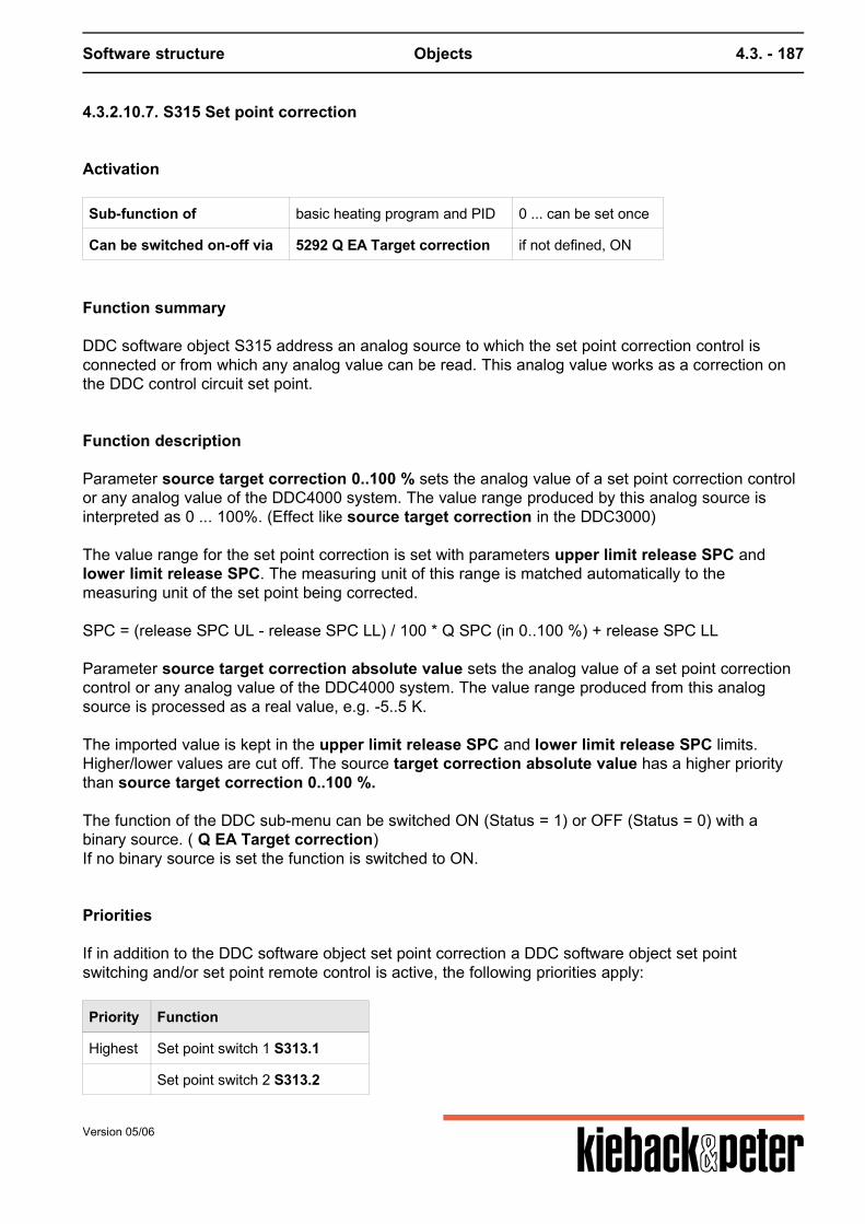
Software structure Objects 4.3. - 187
4.3.2.10.7. S315 Set point correction
Activation
Sub-function of basic heating program and PID 0 ... can be set once
Can be switched on-off via 5292 Q EA Target correction if not defined, ON
Function summary
DDC software object S315 address an analog source to which the set point correction control isconnected or from which any analog value can be read. This analog value works as a correction onthe DDC control circuit set point.
Function description
Parameter source target correction 0..100 % sets the analog value of a set point correction controlor any analog value of the DDC4000 system. The value range produced by this analog source isinterpreted as 0 ... 100%. (Effect like source target correction in the DDC3000) The value range for the set point correction is set with parameters upper limit release SPC andlower limit release SPC. The measuring unit of this range is matched automatically to themeasuring unit of the set point being corrected. SPC = (release SPC UL - release SPC LL) / 100 * Q SPC (in 0..100 %) + release SPC LL Parameter source target correction absolute value sets the analog value of a set point correctioncontrol or any analog value of the DDC4000 system. The value range produced from this analogsource is processed as a real value, e.g. -5..5 K. The imported value is kept in the upper limit release SPC and lower limit release SPC limits.Higher/lower values are cut off. The source target correction absolute value has a higher prioritythan source target correction 0..100 %. The function of the DDC sub-menu can be switched ON (Status = 1) or OFF (Status = 0) with abinary source. ( Q EA Target correction)If no binary source is set the function is switched to ON.
Priorities
If in addition to the DDC software object set point correction a DDC software object set pointswitching and/or set point remote control is active, the following priorities apply:
Priority Function
Highest Set point switch 1 S313.1
Set point switch 2 S313.2
Version 05/06
Software structure Objects 4.3. - 188
Priority Function
Set point switch 3 S313.3
Set point switch 4 S313.4
Set point remote control S316
lowest Set point correction S315
Example
DDC control circuit setpoint to be corrected
Lower limit SPC release Upper limit SPC release valid range for a setpoint correction
20°C -4 6 16 °C to 26 °C
5mBar 0 2 5 mBar to 7 mBar
Note
Basic heating program:The DDC submenu set point correction only works for "day regulation".The set point correction influences KH (parallel movement of heating curve) if the DDC sub-menu15318 room correction or 15300 optimization is not active. TStarget new = TStarget + target correction If DDC room correction or optimize sub-menus are active the room set point TRtarget is changed bythe set point correction. This, for example, influences the economy function and the start set point foractive room correction. TRtarget new = TRtarget + target correction Room correction: TStarget new = TStarget -(Roomtemp – TRtarget new) * ER correction Optimization: NO TStarget correction Basic PID program:In this basic program the set point correction works on the current set point XS current.XS current new = XS current + target correction
Parameters
No. name of parameter parameter typ min max init unit
5290 Q100Q EA Setpoint Correction
actual value deletablefloat
0 100 deleted %
Version 05/06

Software structure Objects 4.3. - 189
No. name of parameter parameter typ min max init unit
5291 QSource Setpoint Correction
actual value deletablefloat
-infinity +infinity deleted --
5292 EAQ EA Setpoint Correction
actual value deletableboolean
-- -- deleted --
5293 release SWK set pointfloat
-infinity +infinity -5 K
5294 Release SWK above set pointfloat
-infinity +infinity 5 --
Version 05/06
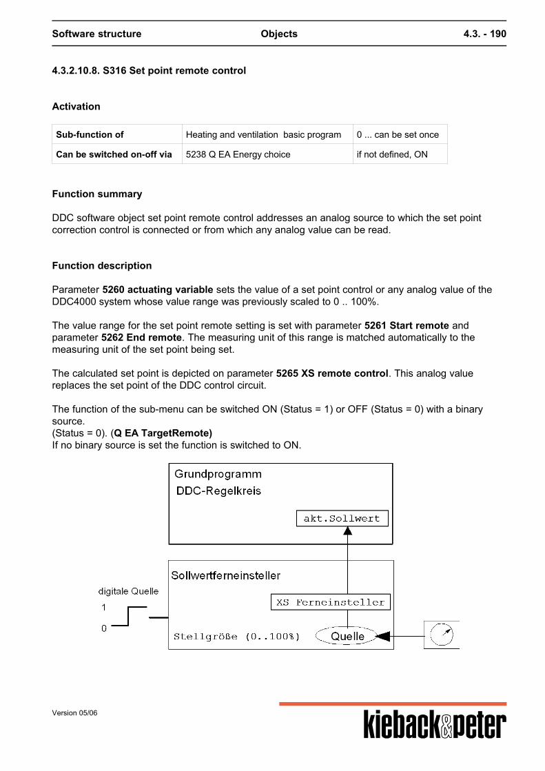
Software structure Objects 4.3. - 190
4.3.2.10.8. S316 Set point remote control
Activation
Sub-function of Heating and ventilation basic program 0 ... can be set once
Can be switched on-off via 5238 Q EA Energy choice if not defined, ON
Function summary
DDC software object set point remote control addresses an analog source to which the set pointcorrection control is connected or from which any analog value can be read.
Function description
Parameter 5260 actuating variable sets the value of a set point control or any analog value of theDDC4000 system whose value range was previously scaled to 0 .. 100%. The value range for the set point remote setting is set with parameter 5261 Start remote andparameter 5262 End remote. The measuring unit of this range is matched automatically to themeasuring unit of the set point being set. The calculated set point is depicted on parameter 5265 XS remote control. This analog valuereplaces the set point of the DDC control circuit. The function of the sub-menu can be switched ON (Status = 1) or OFF (Status = 0) with a binarysource.(Status = 0). (Q EA TargetRemote)If no binary source is set the function is switched to ON.
Version 05/06
Software structure Objects 4.3. - 191
Priorities
If in addition to the DDC software object set point remote control a DDC software object set pointswitching and/or set point correction is active, the following priorities apply:
Priority Function
Highest S313.1 Set point switch 1
S313.2 Set point switch 2
S313.3 Set point switch 3
S313.4 Set point switch 4
S316 Set point remote control
lowest S315 Set point correction
Example:
5261 Start remote 5262 End remote 5265 XS remote control at 0 ..100% value change
10 °C 25 °C 10 °C .. 25 °C
20 %rF 80 %rF 20 %rF .. 80 %rF
0 mBar 5 mBar 0 mBar .. 5 mBar
Note
Basic heating program:The DDC submenu set point correction only works for "day regulation". The set point correction influences KH (parallel movement of heating curve) if the DDC softwareobject S318 room correction or S300 optimization is not active. TStarget correction = XS remote control = (End remote - start remote) * actuating variable / 100 % +start remote TStargetnew = TStarget + TStarget correction If the DDC software object room correction or optimize are active the room set point TRtarget ischanged by the XS remote control. This, for example, influences the economy function and the startset point for active room correction. Room correction: TStargetcorrection = (Room temp - XS remote control) * ER Optimization: NO TStarget correction Basic PID program:In this basic program the set point remote control works on the current set point XS current.
Version 05/06

Software structure Objects 4.3. - 192
XS current = XS remote control = (End remote - start remote) * actuating variable / 100 % + startremote
Parameters
No. name of parameter parameter typ min max init unit
5260 Set size actual value deletablefloat
0 100 deleted --
5261 AnfBegin remote
set pointinteger
-2147483648 2147483647 0 --
5262 EndEnd remote
set pointinteger
-2147483648 2147483647 50 --
5263 EAQ EA setpoint remote
actual value deletableboolean
-- -- deleted --
5265 XS Remote setting actual valuefloat
-infinity +infinity 0 --
Version 05/06
Software structure Objects 4.3. - 193
4.3.2.10.9. S317 XP switching
Activation
Sub-function of basic heating program and PID 0 ... can be set once
Can be switched on-off via 5306 Q XP switching if not defined, ON
Function summary
DDC control circuit control setting parameters are switched with the DDC sub-menu XP switching.Depending on a binary source the proportional ranges of the Y outputs, the rate and regulatingperiods can be switched.
Function description
The binary source is set in parameter source XP switching.If the digital source Q XP switching is "1" or "---" the controller setting parameters are replaced bythe set setting values.The working XP switching is displayed via internal contact I20 XP switching in the basic heatingprogram or PID. Note:In the basic heating program I20 XP switching only becomes "1" if XPY1 changes. Only changes TNNew and/or rate New; I20 XP switch remains "0". I20 XP switch can also be "1" as a result of alimit.
Priorities
The DDC sub-menus limitation menus 1 and 2 work before the XP switch.
Priority Function
Highest Limitation 1 S312.1
Cascade (only PID) S303
Limitation 2 S312.2
XP switching S317
lowest Structure delay start-up S304
Special Functions
Depending on the reset time tN set in the basic program theXPY (basic program) is switched to the XPY (XP switching) gliding and vice versa.
Version 05/06

Software structure Objects 4.3. - 194
Parameters
No. name of parameter parameter typ min max init unit
5300 XPY1XPY1 New
set pointfloat
0,5 999,9 50 K
5301 XPY2XPY2 New
set pointfloat
0,5 999,9 50 K
5302 XPY3XPY3 New
set pointfloat
0,5 999,9 50 K
5303 XPY4XPY4 New
set pointfloat
0,5 999,9 50 K
5304 tNTn New
set point deletablefloat
0,5 99 3 min
5305 dVorhalt
set point deletableinteger
1 99 deleted s
5306 QQ XP change overR
actual value deletableboolean
-- -- deleted --
i020 XP Changeover actual valueboolean
-- -- 0 --
Version 05/06
Software structure Objects 4.3. - 195
4.3.2.10.10. S318 Room correction
Activation
Sub-function of basic heating program can be set once
Can be switched on-off via 5384 Q EA Room correction if not defined, ON
Function summary
The basic heating program controls the supply temperature due to the weather. The set point of thesupply temperature is calculated as per the heating curve, which in turn is stipulated by the KH(parallel movement) and EF (steepness) parameters.The calculated start set point is corrected with the DC software object room correction if thetemperature in the reference room varies from the target room temperature value set.The correction occurs by the parallel movement of the heating curve.
Function description
The determined target supply temperature (5151 TStarget current) is corrected by the roomcorrection DDC software object when the room temperature source parameter 5381 Q room sensorRK varies from the target room temperature value set in the 5180 TRtarget (day operation) or 5181TRmin (night operation) parameters. The 5382 ER correction parameter determines the influence of the normal variance from the targetroom value to the correction of the target starting temperature value. Correction target starting value = XW Room * ER Corr Day: TStarget current = TStarget heating curve - (room temp. - TR target) * ERNight: TStarget current = TStarget heating line + TS abs - (room temp. - TR min) * ER Example:Heating curve with EF = 2.If the room temperature is too low the KH is raised. Therefore the target supply temperature is raised.If the room temperature is too high the KH is lowered. Therefore the target supply temperature islowered. If the room temperature falls faster than 2K/h, after the passing of a delay period 5383 delay RK thetarget supply temperature is corrected. This suppresses short-term set point corrections, e.g. if awindow was opened for a short period of time. If this delay is not wanted the 5383 delay RK entryshould be deleted with [CE] (basic). The function of the DDC software object can be switched ON (Status = 1) or OFF (Status = 0) with abinary source. ( Q EA room correction)If no binary source is set the function is switched to ON.
Version 05/06
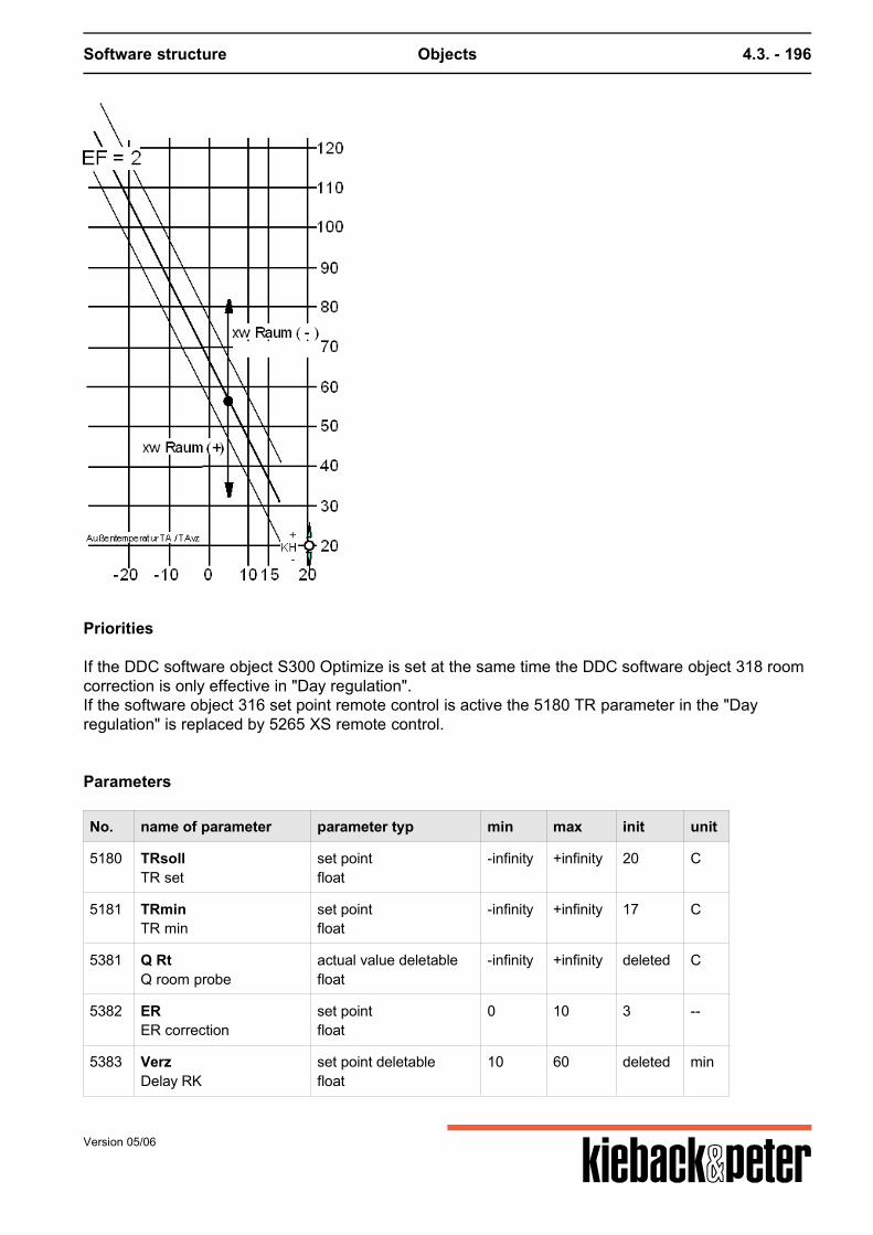
Software structure Objects 4.3. - 196
Priorities
If the DDC software object S300 Optimize is set at the same time the DDC software object 318 roomcorrection is only effective in "Day regulation".If the software object 316 set point remote control is active the 5180 TR parameter in the "Dayregulation" is replaced by 5265 XS remote control.
Parameters
No. name of parameter parameter typ min max init unit
5180 TRsollTR set
set pointfloat
-infinity +infinity 20 C
5181 TRminTR min
set pointfloat
-infinity +infinity 17 C
5381 Q RtQ room probe
actual value deletablefloat
-infinity +infinity deleted C
5382 ERER correction
set pointfloat
0 10 3 --
5383 VerzDelay RK
set point deletablefloat
10 60 deleted min
Version 05/06
Software structure Objects 4.3. - 197
No. name of parameter parameter typ min max init unit
5384 EAQ EA Room correction
actual value deletableboolean
-- -- deleted --
Par.No Parameter name, plaintext
Description
Input Ed. lower limit upper limit specification Unit
Activation parameter
5384 Q EA room correction Activate,deactivatefunction
x 0 1 ---
Parameters
5381 Q room sensor measuredroomtemperature
x -? ? --- °C
5382 ER correction InfluenceonTStarget
x 0.0 10.0 3.0
5383 Delay RK Delaytime forroomcorrection
x 10 60 --- min
5180 TR target Targetroomtemperature dayoperation
x -? ? 20.0 °C
5181 TR min Targetroomtemperature nightoperation
x -? ? 17.0 °C
Parameter from the basicprogram (describedthere)
5151 TStarget current calculatesupplytemperature
x
Version 05/06
Software structure Objects 4.3. - 198
4.3.2.10.11. S319 Standby
Activation
Sub-function of basic heating program 0 ... can be set once
Can be switched on-off via 5397 Q EA Standby if not defined, ON
Function summary
The stand-by DDC software object has the function of switching off the DDC control if a certainoutside temperature is exceeded. The DDC control is only re-started if the outside temperature islower than a stipulated value. It is switched on and off depending on the selected standby type (seebelow).
Function description
For the standby function the outside temperature (Source TO) of the basic heating program applieswhen no source is entered in the 5392 Q StandBy parameter. It is possible to parameterize anothersource, e. g. an average outside temperature. This source is then prioritized higher than the basicprogram (Source TO). If 5391 Standby type "ZQD" is selected, the stand by function depends on the average temperature,which is either formed by the outside temperatureSource TO or from Q StandBy. In Standby type"MRP" the absolute temperatures are used as the criterion. For standby type = MRP the following applies: If the outside temperature exceeds the limiting values stated in the TASBY day or TASBY nightparameters the following switching functions are executed 1 hour after exceeding the limitationvalues:
the internal contact I003 boiler request of the basic heating program switches off, I003 = 0with a hunting time stipulated in the basic heating program pump hunting the internal contact I001Pump ON switches off, I001 = 0the internal contact I008 Stand By switches on, I008 = 1
Version 05/06
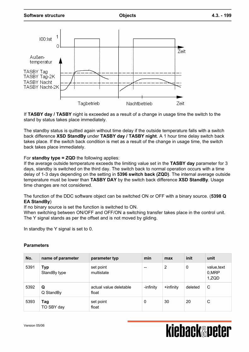
Software structure Objects 4.3. - 199
If TASBY day / TASBY night is exceeded as a result of a change in usage time the switch to thestand by status takes place immediately. The standby status is quitted again without time delay if the outside temperature falls with a switchback difference XSD StandBy under TASBY day / TASBY night. A 1 hour time delay switch backtakes place. If the switch back condition is met as a result of the change in usage time, the switchback takes place immediately. For standby type = ZQD the following applies:If the average outside temperature exceeds the limiting value set in the TASBY day parameter for 3days, standby is switched on the third day. The switch back to normal operation occurs with a timedelay of 1-3 days depending on the setting in 5396 switch back (ZQD). The internal average outsidetemperature must be lower than TASBY DAY by the switch back difference XSD StandBy. Usagetime changes are not considered. The function of the DDC software object can be switched ON or OFF with a binary source. (5398 QEA StandBy)If no binary source is set the function is switched to ON.When switching between ON/OFF and OFF/ON a switching transfer takes place in the control unit.The Y signal stands as per the offset and is not moved by gliding. In standby the Y signal is set to 0.
Parameters
No. name of parameter parameter typ min max init unit
5391 TypStandBy type
set pointmultistate
-- 2 0 value,text0,MRP1,ZQD
5392 QQ StandBy
actual value deletablefloat
-infinity +infinity deleted C
5393 TagTO SBY day
set pointfloat
0 30 20 C
Version 05/06
Software structure Objects 4.3. - 200
No. name of parameter parameter typ min max init unit
5394 NachtTASBY night
set pointfloat
0 30 12 C
5395 xsdXSD StandBy
set pointfloat
1 20 2 K
5396 RuecksBack switch (ZQD)
set pointinteger
1 3 1 d
5397 EAQ EA StandBy
actual value deletableboolean
-- -- deleted --
i008 StByStandBy
actual valueboolean
-- -- 1 --
Version 05/06
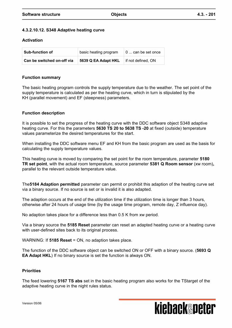
Software structure Objects 4.3. - 201
4.3.2.10.12. S348 Adaptive heating curve
Activation
Sub-function of basic heating program 0 ... can be set once
Can be switched on-off via 5639 Q EA Adapt HKL if not defined, ON
Function summary
The basic heating program controls the supply temperature due to the weather. The set point of thesupply temperature is calculated as per the heating curve, which in turn is stipulated by theKH (parallel movement) and EF (steepness) parameters.
Function description
It is possible to set the progress of the heating curve with the DDC software object S348 adaptiveheating curve. For this the parameters 5630 TS 20 to 5638 TS -20 at fixed (outside) temperaturevalues parameterize the desired temperatures for the start. When installing the DDC software menu EF and KH from the basic program are used as the basis forcalculating the supply temperature values. This heating curve is moved by comparing the set point for the room temperature, parameter 5180TR set point, with the actual room temperature, source parameter 5381 Q Room sensor (xw room),parallel to the relevant outside temperature value. The5184 Adaption permitted parameter can permit or prohibit this adaption of the heating curve setvia a binary source. If no source is set or is invalid it is also adapted. The adaption occurs at the end of the utilization time if the utilization time is longer than 3 hours,otherwise after 24 hours of usage time (by the usage time program, remote day, Z influence day). No adaption takes place for a difference less than 0.5 K from xw period. Via a binary source the 5185 Reset parameter can reset an adapted heating curve or a heating curvewith user-defined sites back to its original process. WARNING: If 5185 Reset = ON, no adaption takes place. The function of the DDC software object can be switched ON or OFF with a binary source. (5693 QEA Adapt HKL) If no binary source is set the function is always ON.
Priorities
The feed lowering 5167 TS abs set in the basic heating program also works for the TStarget of theadaptive heating curve in the night rules status.
Version 05/06
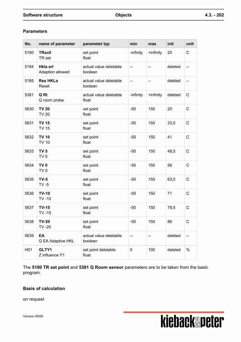
Software structure Objects 4.3. - 202
Parameters
No. name of parameter parameter typ min max init unit
5180 TRsollTR set
set pointfloat
-infinity +infinity 20 C
5184 Hkla erlAdaption allowed
actual value deletableboolean
-- -- deleted --
5185 Res HKLaReset
actual value deletableboolean
-- -- deleted --
5381 Q RtQ room probe
actual value deletablefloat
-infinity +infinity deleted C
5630 TV 20TV 20
set pointfloat
-50 150 20 C
5631 TV 15TV 15
set pointfloat
-50 150 33,5 C
5632 TV 10TV 10
set pointfloat
-50 150 41 C
5633 TV 5TV 5
set pointfloat
-50 150 48,5 C
5634 TV 0TV 0
set pointfloat
-50 150 56 C
5635 TV-5TV -5
set pointfloat
-50 150 63,5 C
5636 TV-10TV -10
set pointfloat
-50 150 71 C
5637 TV-15TV -15
set pointfloat
-50 150 78,5 C
5638 TV-20TV -20
set pointfloat
-50 150 86 C
5639 EAQ EA Adaptive HKL
actual value deletableboolean
-- -- deleted --
H01 GLTY1Z influence Y1
set point deletablefloat
0 100 deleted %
The 5180 TR set point and 5381 Q Room sensor parameters are to be taken from the basicprogram.
Basis of calculation
on request
Version 05/06

Software structure Objects 4.3. - 203
Version 05/06
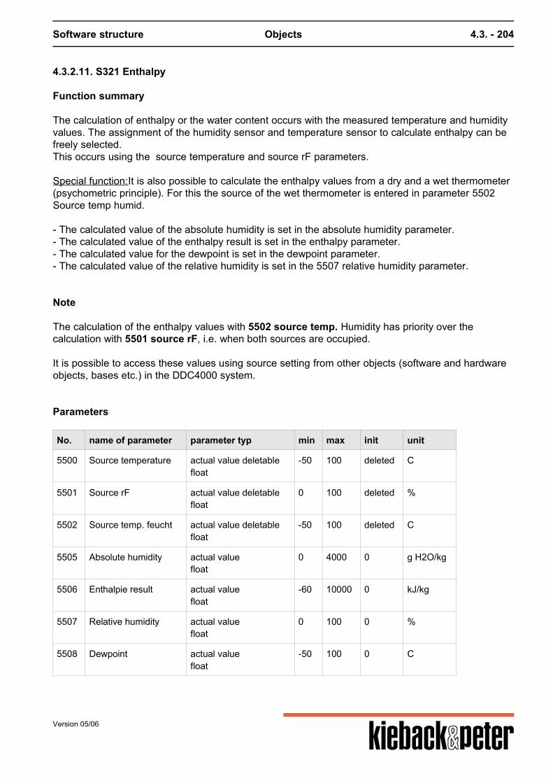
Software structure Objects 4.3. - 204
4.3.2.11. S321 Enthalpy
Function summary
The calculation of enthalpy or the water content occurs with the measured temperature and humidityvalues. The assignment of the humidity sensor and temperature sensor to calculate enthalpy can befreely selected.This occurs using the source temperature and source rF parameters. Special function:It is also possible to calculate the enthalpy values from a dry and a wet thermometer(psychometric principle). For this the source of the wet thermometer is entered in parameter 5502Source temp humid.
- The calculated value of the absolute humidity is set in the absolute humidity parameter.- The calculated value of the enthalpy result is set in the enthalpy parameter.- The calculated value for the dewpoint is set in the dewpoint parameter.- The calculated value of the relative humidity is set in the 5507 relative humidity parameter.
Note
The calculation of the enthalpy values with 5502 source temp. Humidity has priority over thecalculation with 5501 source rF, i.e. when both sources are occupied. It is possible to access these values using source setting from other objects (software and hardwareobjects, bases etc.) in the DDC4000 system.
Parameters
No. name of parameter parameter typ min max init unit
5500 Source temperature actual value deletablefloat
-50 100 deleted C
5501 Source rF actual value deletablefloat
0 100 deleted %
5502 Source temp. feucht actual value deletablefloat
-50 100 deleted C
5505 Absolute humidity actual valuefloat
0 4000 0 g H2O/kg
5506 Enthalpie result actual valuefloat
-60 10000 0 kJ/kg
5507 Relative humidity actual valuefloat
0 100 0 %
5508 Dewpoint actual valuefloat
-50 100 0 C
Version 05/06
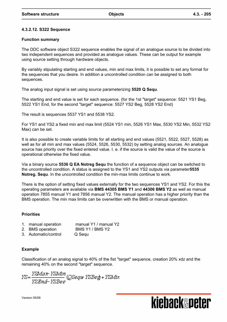
Software structure Objects 4.3. - 205
4.3.2.12. S322 Sequence
Function summary
The DDC software object S322 sequence enables the signal of an analogue source to be divided intotwo independent sequences and provided as analogue values. These can be output for exampleusing source setting through hardware objects. By variably stipulating starting and end values, min and max limits, it is possible to set any format forthe sequences that you desire. In addition a uncontrolled condition can be assigned to bothsequences. The analog input signal is set using source parameterizing 5520 Q Sequ. The starting and end value is set for each sequence. (for the 1st "target" sequence: 5521 YS1 Beg,5522 YS1 End, for the second "target" sequence: 5527 YS2 Beg, 5528 YS2 End) The result is sequences 5537 YS1 and 5538 YS2. For YS1 and YS2 a fixed min and max limit (5524 YS1 min, 5526 YS1 Max, 5530 YS2 Min, 5532 YS2Max) can be set. It is also possible to create variable limits for all starting and end values (5521, 5522, 5527, 5528) aswell as for all min and max values (5524, 5526, 5530, 5532) by setting analog sources. An analoguesource has priority over the fixed entered value. I. e. if the source is valid the value of the source isoperational otherwise the fixed value. Via a binary source 5536 Q EA Notreg Sequ the function of a sequence object can be switched tothe uncontrolled condition. A status is assigned to the YS1 and YS2 outputs via parameter5535Notreg. Sequ. In the uncontrolled condition the min-max limits continue to work. There is the option of setting fixed values externally for the two sequences YS1 and YS2. For this theoperating parameters are available via BMS 44305 BMS Y1 and 44306 BMS Y2 as well as manualoperation 7855 manual Y1 and 7856 manual Y2. The manual operation has a higher priority than theBMS operation. The min max limits can be overwritten with the BMS or manual operation.
Priorities
1. manual operation manual Y1 / manual Y22. BMS operation BMS Y1 / BMS Y23. Automatic/control Q Sequ Example Classification of an analog signal to 40% of the fist "target" sequence, creation 20% xdz and theremaining 40% on the second "target" sequence.
Version 05/06
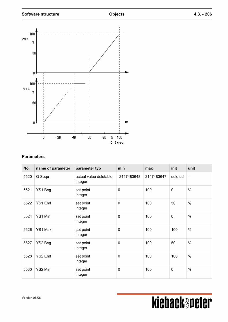
Software structure Objects 4.3. - 206
Parameters
No. name of parameter parameter typ min max init unit
5520 Q Sequ actual value deletableinteger
-2147483648 2147483647 deleted --
5521 YS1 Beg set pointinteger
0 100 0 %
5522 YS1 End set pointinteger
0 100 50 %
5524 YS1 Min set pointinteger
0 100 0 %
5526 YS1 Max set pointinteger
0 100 100 %
5527 YS2 Beg set pointinteger
0 100 50 %
5528 YS2 End set pointinteger
0 100 100 %
5530 YS2 Min set pointinteger
0 100 0 %
Version 05/06
Software structure Objects 4.3. - 207
No. name of parameter parameter typ min max init unit
5532 YS2 Max set pointinteger
0 100 100 %
5535 Not reg sequ set pointselection list
-- -- 0 selection listNo.,text0,Y11,Y2
5536 Q EA Not reg Sequ actual value deletableboolean
-- -- deleted --
5537 YS1 actual valueinteger
0 100 0 %
5538 YS2 set pointinteger
0 100 0 %
7855 Hand Y1 set point deletableinteger
0 100 deleted %
7856 Hand Y2 set point deletableinteger
0 100 deleted %
7857 BMS Y1 set point deletableinteger
0 100 deleted %
7858 BMS Y2 actual value deletableinteger
0 100 deleted %
Version 05/06
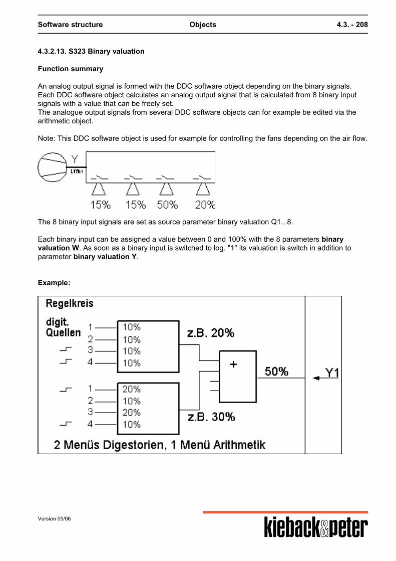
Software structure Objects 4.3. - 208
4.3.2.13. S323 Binary valuation
Function summary
An analog output signal is formed with the DDC software object depending on the binary signals.Each DDC software object calculates an analog output signal that is calculated from 8 binary inputsignals with a value that can be freely set.The analogue output signals from several DDC software objects can for example be edited via thearithmetic object. Note: This DDC software object is used for example for controlling the fans depending on the air flow.
The 8 binary input signals are set as source parameter binary valuation Q1...8. Each binary input can be assigned a value between 0 and 100% with the 8 parameters binaryvaluation W. As soon as a binary input is switched to log. "1" its valuation is switch in addition toparameter binary valuation Y.
Example:
Version 05/06
Software structure Objects 4.3. - 209
Parameters
No. name of parameter parameter typ min max init unit
5540 YBinary values Y
actual valueinteger
0 100 0 %
5541 Binary values Q1 actual value deletableboolean
-- -- deleted --
5542 Binary values Q2 set point deletableboolean
-- -- deleted --
5543 Binary values Q3 actual value deletableboolean
-- -- deleted --
5544 Binary values Q4 actual value deletableboolean
-- -- deleted --
5545 Binary values W1 set pointinteger
0 100 25 %
5546 Binary values W2 set pointinteger
0 100 25 %
5547 Binary values W3 set pointinteger
0 100 25 %
5548 Binary values W4 set pointinteger
0 100 25 %
5549 Binary values W5 set pointinteger
0 100 25 %
5550 Binary values W6 set pointinteger
0 100 25 %
5551 Binary values W7 set pointinteger
0 100 25 %
5552 Binary values W8 set pointinteger
0 100 25 %
5555 Binary values Q5 actual value deletableboolean
-- -- deleted --
5556 Binary values Q6 actual value deletableboolean
-- -- deleted --
5557 Binary values Q7 actual value deletableboolean
-- -- deleted --
5558 Binary values Q8 actual value deletableboolean
-- -- deleted --
Version 05/06
Software structure Objects 4.3. - 210
4.3.2.14. S324 Scaling
Function summary
Mit dem DDC-Softwareobjekt S324 Skalierung kann einem analogen Signal ein neuer Wertebereichzugeordnet werden. Der Wertebereich wird durch einen Anfangs- und einen Endwert definiert.
A new value range can be assigned to an analog signal with the DDC software object S324 scaling.The value range is defined by a start and an end value. In parameter 5550 Q Scal sensor the source of the analog signal to be scaled is set. Each analogsignal in the DDC4000 system can be scaled. The scaling refers to the value range of the inputmagnitude (0..100%). Parameters 5551 start scaling and 5552 End scaling set the value range. The scaled value isprovided in parameter 5554 scaling value. Using parameter 5553 min output delta the analog signal can be calmed, e.g. a sensor value.If e.g. "0.0" is entered all changes are calculated and provided as a scaled value.If e.g. "0.5" is entered all changes greater than 0.5 units are re-calculated and provided as a scaledvalue. Parameter 5555 attentuation works as a PT1-Glide. If the input signal value changes (5550 Q Scalsensor) in jumps a 63% change in value from the original input jump is achieved at the output (5554Value Scaling) after the attentuation time.
Please note:
The analog signal for measuring element KP10 (sensor inputs that are set for KP10) can not bescaled. If the input signal (5550 Q Scal sensor) is deleted or invalid the output (5554 value scaling) = 0,0. If the input signal < 0 %, the output signal takes the value of its lower limit (5551 start scaling) or if >100 % the value of its upper limit (5552 End scaling). Scaling value = (End of scaling – Start of scaling) * Scal sensor / 100 % + start of scaling
Version 05/06
Software structure Objects 4.3. - 211
Example 1:A 0..10 V signal should be converted to0..350 m³/h (depicted as 0.100 %) Start of range 0.0 (0 %)End of range 350.0 (100 %)Unit m³/h
Example 2:An analog signal (0..100 %) should beconverted into Fahrenheit Start of range -58.0 (= 0 %)End of range 302.0 (= 100 %)Unit F
Parameters
No. name of parameter parameter typ min max init unit
5550 Q_BQ scal sensor
actual value deletablefloat
-infinity +infinity deleted --
5551 AnfBegin scaling
set pointfloat
-infinity +infinity 0 --
5552 EndeEnd scaling
set pointfloat
-infinity +infinity 0 --
5553 Deltamin. output delta
set pointfloat
0 10 0 --
5554 WertValue scaling
actual valuefloat
-infinity +infinity 0 --
5555 PT1Dampening
set point deletableinteger
1 3600 deleted s
Version 05/06

Software structure Objects 4.3. - 212
Version 05/06
Software structure Objects 4.3. - 213
4.3.2.15. S325 MinMaxAverage
Function summary
Using the DDC software object S325 min/max/average the smallest, largest and average value canbe calculated from up to 8 analog signals. Each of the 8 analog signals can be occupied with aweighting factor. The 8 analog signals are recorded via source parameterizing 1..8 MMM sensor 1..8. The factors forweighting the individual analog signals are to be set in 11..18 MMM Factor 1..8. In addition via the binary sources 21..28 Q EA sensor 1..8 there is also the opportunity to removeeach individual analog source from the min/max/average calculation. If the binary source is switchedon or not source set the corresponding analog source is included as per its factor in the calculation. The calculated values for the min, max and average calculation are provided on parameters 31 Minselection, 32 Max selection and 33 average. It is possible to access these values using sourcesetting from other software and hardware objects of the DDC4000 system.
Parameters
No. name of parameter parameter typ min max init unit
1 B1MMM Sensor 1
actual value deletablefloat
-infinity +infinity deleted --
2 B2MMM Sensor 2
actual value deletablefloat
-infinity +infinity deleted --
3 B3MMM Sensor 3
actual value deletablefloat
-infinity +infinity deleted --
4 B4MMM Sensor 4
actual value deletablefloat
-infinity +infinity deleted --
5 B5MMM Sensor 5
actual value deletablefloat
-infinity +infinity deleted --
6 B6MMM Sensor 6
actual value deletablefloat
-infinity +infinity deleted --
7 B7MMM Sensor 7
actual value deletablefloat
-infinity +infinity deleted --
8 B8MMM Sensor 8
actual value deletablefloat
-infinity +infinity deleted --
11 F1MMM Factor 1
set pointfloat
0 10 1 --
12 F2MMM Factor 2
set pointfloat
0 10 1 --
Version 05/06
Software structure Objects 4.3. - 214
No. name of parameter parameter typ min max init unit
13 F3MMM Factor 3
set pointfloat
0 10 1 --
14 F4MMM Factor 4
set pointfloat
0 10 1 --
15 F5MMM Factor 5
set pointfloat
0 10 1 --
16 F6MMM Factor 6
set pointfloat
0 10 1 --
17 F7MMM Factor 7
set pointfloat
0 10 1 --
18 F8MMM Factor 8
set pointfloat
0 10 1 --
21 QEA1Q EA Sensor 1
actual value deletableboolean
-- -- deleted --
22 QEA2Q EA Sensor 2
actual value deletableboolean
-- -- deleted --
23 QEA3Q EA Sensor 3
actual value deletableboolean
-- -- deleted --
24 QEA4Q EA Sensor 4
actual value deletableboolean
-- -- deleted --
25 QEA5Q EA Sensor 5
actual value deletableboolean
-- -- deleted --
26 QEA6Q EA Sensor 6
actual value deletableboolean
-- -- deleted --
27 QEA7Q EA Sensor 7
actual value deletableboolean
-- -- deleted --
28 QEA8Q EA Sensor 8
actual value deletableboolean
-- -- deleted --
31 minMin select
actual valuefloat
-infinity +infinity 0 --
32 maxMax select
actual valuefloat
-infinity +infinity 0 --
33 mittelMiddle value
actual valuefloat
-infinity +infinity 0 --
Version 05/06
Software structure Objects 4.3. - 215
4.3.2.16. S326 Time gliding
Activation
Sub-function of - 10 times can be set
Function summary
This DDC software object can be used for example as a command value in DDC software objects,e.g. for "time-dependent" glide of a set point.
Function description
With the DDC software object time glide a value that is larger or smaller depending on the time iscreated. The bigger or smaller is set as a slope in the parameters 5680 slope +/h and 5681 slope -/h. For this the desired slope is defined as a numerical value 0.01...999 per hour. The value produced from the slope (positive or negative) and the time passed is indicated inparameter 5684 time glide. A starting value and an end value must be stipulated. The gliding starts with the starting value andends with the end value. It is possible to access this value with source parameterizing. The time glide is controlled as follows using the two binary source parameters timegl/ and timegl\:
Time gliding
Timegl/ Timegl\ Start value < End value Start value > End value
0 0 The value is reset to the start value The value is reset to the start value
1 0 Value becomes larger as per slope+/hStart value -> End value
Value becomes larger as per slope+/hEnd value -> Start value
0 1 Value becomes smaller as per slope+/hEnd value -> Start value
Value becomes smaller as per slope+/hStart value -> End value
1 1 No changes No changes
Version 05/06

Software structure Objects 4.3. - 216
Parameters
No. name of parameter parameter typ min max init unit
5680 Steig+Slope +/h
set pointfloat
0 999 1 --
5681 Steig-Slope -/h
set pointfloat
0 999 1 --
5682 AufTime gl/
actual value deletableboolean
-- -- deleted --
5683 AbTime gl\
actual value deletableboolean
-- -- deleted --
5684 AusgTime slides
actual valuefloat
-infinity +infinity 0 --
5685 StartTime slides
set pointfloat
-infinity +infinity 0 --
Version 05/06
Example

Software structure Objects 4.3. - 217
No. name of parameter parameter typ min max init unit
5686 EndeEnd value
set pointfloat
-infinity +infinity 0 --
Version 05/06
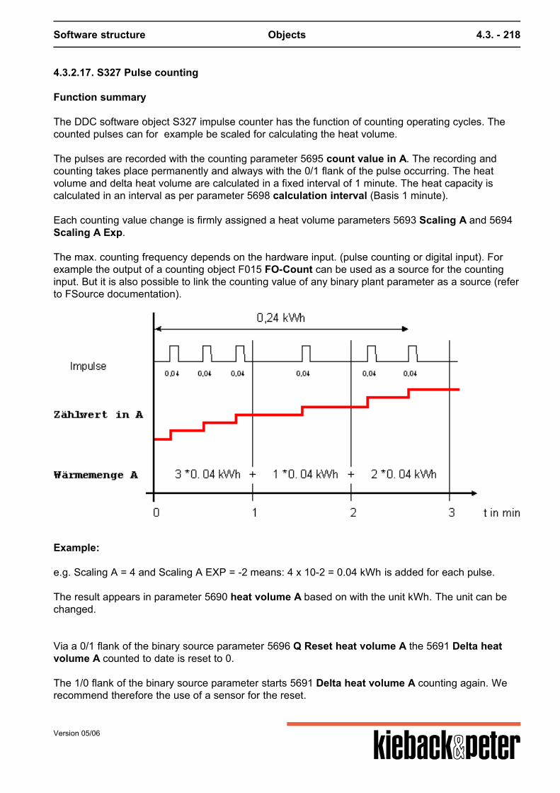
Software structure Objects 4.3. - 218
4.3.2.17. S327 Pulse counting
Function summary
The DDC software object S327 impulse counter has the function of counting operating cycles. Thecounted pulses can for example be scaled for calculating the heat volume. The pulses are recorded with the counting parameter 5695 count value in A. The recording andcounting takes place permanently and always with the 0/1 flank of the pulse occurring. The heatvolume and delta heat volume are calculated in a fixed interval of 1 minute. The heat capacity iscalculated in an interval as per parameter 5698 calculation interval (Basis 1 minute). Each counting value change is firmly assigned a heat volume parameters 5693 Scaling A and 5694Scaling A Exp. The max. counting frequency depends on the hardware input. (pulse counting or digital input). Forexample the output of a counting object F015 FO-Count can be used as a source for the countinginput. But it is also possible to link the counting value of any binary plant parameter as a source (referto FSource documentation).
Example:
e.g. Scaling A = 4 and Scaling A EXP = -2 means: 4 x 10-2 = 0.04 kWh is added for each pulse. The result appears in parameter 5690 heat volume A based on with the unit kWh. The unit can bechanged. Via a 0/1 flank of the binary source parameter 5696 Q Reset heat volume A the 5691 Delta heatvolume A counted to date is reset to 0. The 1/0 flank of the binary source parameter starts 5691 Delta heat volume A counting again. Werecommend therefore the use of a sensor for the reset.
Version 05/06
Software structure Objects 4.3. - 219
The calculated volumes of 5690 heat volume A and 5691 Delta heat volume A can be reset or setby default both by the DDC4000 Central Unit keyboard and the BMS. The function of the DDC software object can be switched ON (Status = 1) or OFF (Status = 0) with abinary source. (5697 Q EA pulse)This makes counting with a certain time range possible. If no binary source is set the function is switched to ON. In parameter 5692 heat capacity A the current calculated heat capacity is entered.
Parameters
No. name of parameter parameter typ min max init unit
5690 Amount of heat A set pointinteger
0 100000000 0 kWh
5691 Delta amount of heat A set pointinteger
0 100000000 0 kWh
5692 Heat power A actual valueinteger
0 100000000 0 kW
5693 Scaling A set pointfloat
0,001 100000 1 --
5694 Scaling A Exp set pointinteger
-9 9 0 --
5695 Impulse in A actual valueinteger
0 2147483647 0 --
5696 Q Reset amount of heat A actual value deletableboolean
-- -- deleted --
5697 Q EA Impulse actual value deletableboolean
-- -- deleted --
5698 Calculation interval set pointinteger
1 60 1 min
Version 05/06
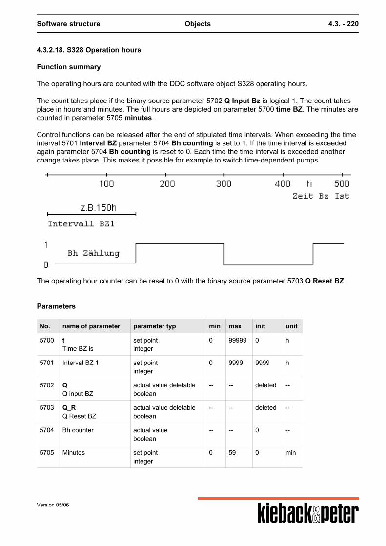
Software structure Objects 4.3. - 220
4.3.2.18. S328 Operation hours
Function summary
The operating hours are counted with the DDC software object S328 operating hours. The count takes place if the binary source parameter 5702 Q Input Bz is logical 1. The count takesplace in hours and minutes. The full hours are depicted on parameter 5700 time BZ. The minutes arecounted in parameter 5705 minutes. Control functions can be released after the end of stipulated time intervals. When exceeding the timeinterval 5701 Interval BZ parameter 5704 Bh counting is set to 1. If the time interval is exceededagain parameter 5704 Bh counting is reset to 0. Each time the time interval is exceeded anotherchange takes place. This makes it possible for example to switch time-dependent pumps.
The operating hour counter can be reset to 0 with the binary source parameter 5703 Q Reset BZ.
Parameters
No. name of parameter parameter typ min max init unit
5700 tTime BZ is
set pointinteger
0 99999 0 h
5701 Interval BZ 1 set pointinteger
0 9999 9999 h
5702 QQ input BZ
actual value deletableboolean
-- -- deleted --
5703 Q_RQ Reset BZ
actual value deletableboolean
-- -- deleted --
5704 Bh counter actual valueboolean
-- -- 0 --
5705 Minutes set pointinteger
0 59 0 min
Version 05/06
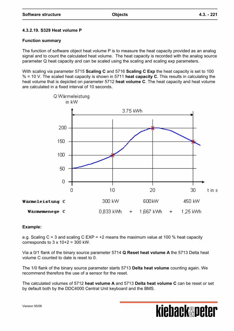
Software structure Objects 4.3. - 221
4.3.2.19. S329 Heat volume P
Function summary
The function of software object heat volume P is to measure the heat capacity provided as an analogsignal and to count the calculated heat volume. The heat capacity is recorded with the analog sourceparameter Q heat capacity and can be scaled using the scaling and scaling exp parameters. With scaling via parameter 5715 Scaling C and 5716 Scaling C Exp the heat capacity is set to 100% = 10 V. The scaled heat capacity is shown in 5711 heat capacity C. This results in calculating theheat volume that is depicted on parameter 5712 heat volume C. The heat capacity and heat volumeare calculated in a fixed interval of 10 seconds.
Example:
e.g. Scaling C = 3 and scaling C EXP = +2 means the maximum value at 100 % heat capacitycorresponds to 3 x 10+2 = 300 kW. Via a 0/1 flank of the binary source parameter 5714 Q Reset heat volume A the 5713 Delta heatvolume C counted to date is reset to 0. The 1/0 flank of the binary source parameter starts 5713 Delta heat volume counting again. Werecommend therefore the use of a sensor for the reset. The calculated volumes of 5712 heat volume A and 5713 Delta heat volume C can be reset or setby default both by the DDC4000 Central Unit keyboard and the BMS.
Version 05/06
Software structure Objects 4.3. - 222
The function of the DDC software object can be switched ON (Status = 1) or OFF (Status = 0) with abinary source (Status = 0). (5717 Q EA Wmber_P)
If no binary source is set the function is switched to ON.
Parameters
No. name of parameter parameter typ min max init unit
5710 Q heat power actual value deletablefloat
0 +infinity deleted kW
5711 Heat power C actual valuefloat
0 100000000 0 kW
5712 Amount of heat C set pointfloat
0 100000000 0 kWh
5713 Delta amount of heat C set pointfloat
0 100000000 0 kWh
5714 Q Reset amount of heat C actual value deletableboolean
-- -- deleted --
5715 Scaling C set pointfloat
0,1 999,9 1 --
5716 Scaling C Exp set pointinteger
-3 3 0 --
5717 Q EA Wmber_P actual value deletableboolean
-- -- deleted --
Version 05/06
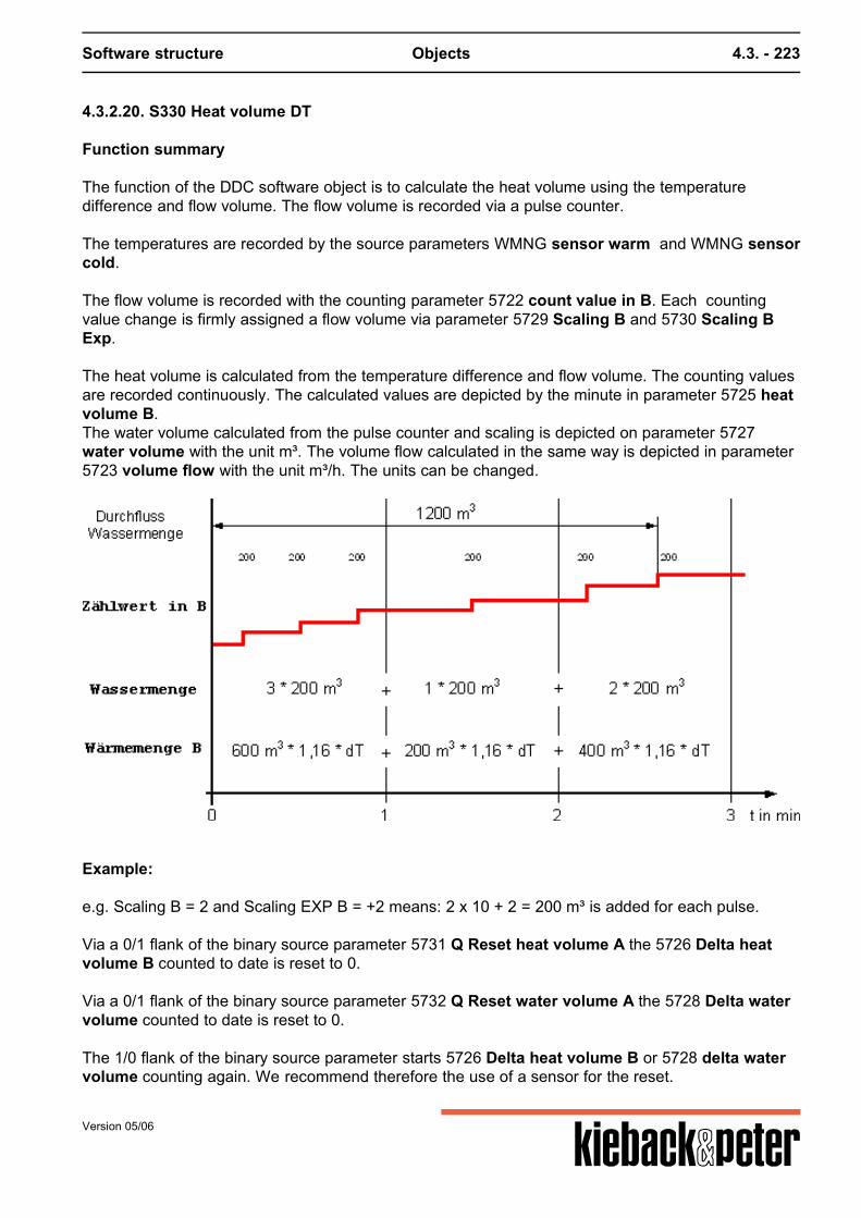
Software structure Objects 4.3. - 223
4.3.2.20. S330 Heat volume DT
Function summary
The function of the DDC software object is to calculate the heat volume using the temperaturedifference and flow volume. The flow volume is recorded via a pulse counter. The temperatures are recorded by the source parameters WMNG sensor warm and WMNG sensorcold. The flow volume is recorded with the counting parameter 5722 count value in B. Each countingvalue change is firmly assigned a flow volume via parameter 5729 Scaling B and 5730 Scaling BExp. The heat volume is calculated from the temperature difference and flow volume. The counting valuesare recorded continuously. The calculated values are depicted by the minute in parameter 5725 heatvolume B.The water volume calculated from the pulse counter and scaling is depicted on parameter 5727water volume with the unit m³. The volume flow calculated in the same way is depicted in parameter5723 volume flow with the unit m³/h. The units can be changed.
Example:
e.g. Scaling B = 2 and Scaling EXP B = +2 means: 2 x 10 + 2 = 200 m³ is added for each pulse. Via a 0/1 flank of the binary source parameter 5731 Q Reset heat volume A the 5726 Delta heatvolume B counted to date is reset to 0. Via a 0/1 flank of the binary source parameter 5732 Q Reset water volume A the 5728 Delta watervolume counted to date is reset to 0. The 1/0 flank of the binary source parameter starts 5726 Delta heat volume B or 5728 delta watervolume counting again. We recommend therefore the use of a sensor for the reset.
Version 05/06
Software structure Objects 4.3. - 224
The calculated volumes of 5725 heat volume B, 5726 Delta heat volume B, 5727 water volumeand 5728 delta water volume can be reset or set by default both by the DDC4000 Central Unitkeyboard and the BMS. The function of the DDC software object can be switched ON (Status = 1) or OFF (Status = 0) with abinary source (Status = 0) (5733 EAWB).If no binary source is set the function is switched to ON.
Note
A counting object F015 FO count can be used for example as a source for the counting input 5722Counting value in B. But it is also possible to link the counting value of any binary plant parameteras a source (refer to FSource documentation).
Parameters
No. name of parameter parameter typ min max init unit
5720 WMNG Sensor warm actual value deletablefloat
-infinity +infinity deleted C
5721 WMNG Sensor kalt actual value deletablefloat
-infinity +infinity deleted C
5722 Impulse in B actual valueinteger
0 2147483647 0 --
5723 Volume current actual valuefloat
0 9999999 0 m/h
5724 Heat power B actual valuefloat
0 100000000 0 kW
5725 Amount of heat B set pointfloat
0 +infinity 0 kWh
5726 Delta WDelta amount of heat B
set pointfloat
0 +infinity 0 kWh
5727 amount of water set pointfloat
0 +infinity 0 m
5728 Delta amount of water set pointfloat
0 +infinity 0 m
5729 Scaling B set pointfloat
0,1 999,9 1 --
5730 Scaling B Exp set pointinteger
-3 3 0 --
5731 Q Reset amount of heat B actual value deletableboolean
-- -- deleted --
Version 05/06
Software structure Objects 4.3. - 225
No. name of parameter parameter typ min max init unit
5732 Q Reset amount of water actual value deletableboolean
-- -- deleted --
5733 EAWBWmCalcEA
actual value deletableboolean
-- -- deleted --
Formulas Q = V * p * cP * DTheat volume = Water volume * 1.16 * DTemperature Q = heat volume (in kWh) V = Volume = water volume (in m³) p = Density of water = 1000 kg/m³ cP = heat capacity = 1.16 Wh/(kg * K) DT = DTemperature = sensor warm – sensor cold (in K)
Version 05/06
Software structure Objects 4.3. - 226
4.3.2.21. S333 Ring counter
Function summary
A maximum of 12 binary outputs are switched onwards cyclically wit the DDC software object S333ring counter. The switching on takes place automatically by stipulating a time span a n d / o r changing the statusof a binary source. After installing the software object the first output 5763 Ring output 1 is switched on. Parameter 5759 starting time provides the opportunity to precisely determine the start of switchingon by including a digital source for example from a time program. The second switching on occursafter the end of the set time span or the first time the binary input Q Ring is switched. The default starting time is deleted, i. e. the calculation of the switching on starts immediately.
The following options are possible for switching the binary outputs:
1. Switching on the binary output to the subsequent output takes place after the end of the timestipulated in parameter 5761 time span. The time is entered in minutes (m³ 1 minute) and/or
2. The switching on of the binary output to the following output is done via a binary source 5762 QRing. This switching on occurs independently of the starting time.
If parameter value 5761 time span is deleted the ring counter stays at the current level. It can onlybe switched on via a binary source. With parameter 5760 Ring number the number of the outputs to be controlled 5763 .. 5774 Ringoutput 1 .. 12 is stipulated. It is possible to control 2 to 12 outputs.
Example
Pump switching
Version 05/06
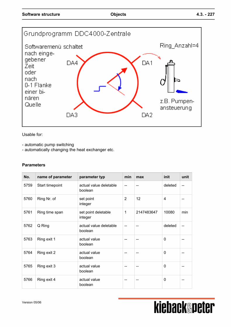
Software structure Objects 4.3. - 227
Usable for: - automatic pump switching- automatically changing the heat exchanger etc.
Parameters
No. name of parameter parameter typ min max init unit
5759 Start timepoint actual value deletableboolean
-- -- deleted --
5760 Ring Nr. of set pointinteger
2 12 4 --
5761 Ring time span set point deletableinteger
1 2147483647 10080 min
5762 Q Ring actual value deletableboolean
-- -- deleted --
5763 Ring exit 1 actual valueboolean
-- -- 0 --
5764 Ring exit 2 actual valueboolean
-- -- 0 --
5765 Ring exit 3 actual valueboolean
-- -- 0 --
5766 Ring exit 4 actual valueboolean
-- -- 0 --
Version 05/06
Software structure Objects 4.3. - 228
No. name of parameter parameter typ min max init unit
5767 Ring exit 5 actual valueboolean
-- -- 0 --
5768 Ring exit 6 actual valueboolean
-- -- 0 --
5769 Ring exit 7 actual valueboolean
-- -- 0 --
5770 Ring exit 8 actual valueboolean
-- -- 0 --
5771 Ring exit 9 actual valueboolean
-- -- 0 --
5772 Ring exit 10 actual valueboolean
-- -- 0 --
5773 Ring exit 11 actual valueboolean
-- -- 0 --
5774 Ring exit 12 actual valueboolean
-- -- 0 --
Version 05/06

Software structure Objects 4.3. - 229
4.3.2.22. S334 Spreadsheet function
Function summary
Using the DDC software object S334 table function a new analog output signal Y is formed from ananalog input signal X. The value assignment occurs via up to 10 value pairs X/Y. The DDC softwareobject is used for example to linearize unlinearities from machine parts in the technical operationplant (e.g. non-linear transfer behavior of heat ransfer units). The analog input signal X is set as source parameter 5791 Tab command value X. The output signal Y calculated in line with up to 10 X/Y value pairs is depicted on parameter 5792Tab output Y. An output signal Y is calculated by interpolation for all input signals that are between the set valuepairs X/Y. This requires complete upward setting for the input signals.
The input signal setting must start with X1/Y1.
No X/Y inputs between the first and last X/Y value pair can be released.
The X values must be set going up: X1 < X2 < X3 ...
The interpolation ends with the last X/Y value pair, e.g. X1/Y1 ... X5/Y5.
Immediately after activating the DDC software object all input parameters (command value, X/Yinputs) are deleted and have to be set first. The Y output signal is set to 0 for this time. If the inputsignal X wanders with an active function beyond the upper/lower value pair X/Y the most recentlycalculated value is retained as output signal Y.
Version 05/06
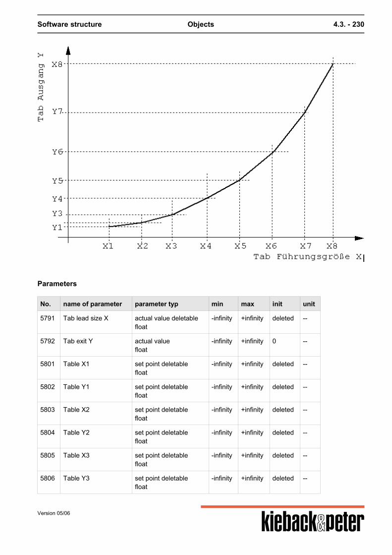
Software structure Objects 4.3. - 230
Parameters
No. name of parameter parameter typ min max init unit
5791 Tab lead size X actual value deletablefloat
-infinity +infinity deleted --
5792 Tab exit Y actual valuefloat
-infinity +infinity 0 --
5801 Table X1 set point deletablefloat
-infinity +infinity deleted --
5802 Table Y1 set point deletablefloat
-infinity +infinity deleted --
5803 Table X2 set point deletablefloat
-infinity +infinity deleted --
5804 Table Y2 set point deletablefloat
-infinity +infinity deleted --
5805 Table X3 set point deletablefloat
-infinity +infinity deleted --
5806 Table Y3 set point deletablefloat
-infinity +infinity deleted --
Version 05/06
Software structure Objects 4.3. - 231
No. name of parameter parameter typ min max init unit
5807 Table X4 set point deletablefloat
-infinity +infinity deleted --
5808 Table Y4 set point deletablefloat
-infinity +infinity deleted --
5809 Table X5 set point deletablefloat
-infinity +infinity deleted --
5810 Table Y5 set point deletablefloat
-infinity +infinity deleted --
5811 Table X6 set point deletablefloat
-infinity +infinity deleted --
5812 Table Y6 set point deletablefloat
-infinity +infinity deleted --
5813 Table X7 set point deletablefloat
-infinity +infinity deleted --
5814 Table Y7 set point deletablefloat
-infinity +infinity deleted --
5815 Table X8 set point deletablefloat
-infinity +infinity deleted --
5816 Table Y8 set point deletablefloat
-infinity +infinity deleted --
5817 Table X9 set point deletablefloat
-infinity +infinity deleted --
5818 Table Y9 set point deletablefloat
-infinity +infinity deleted --
5819 Table X10 set point deletablefloat
-infinity +infinity deleted --
5820 Table Y10 set point deletablefloat
-infinity +infinity deleted --
Version 05/06
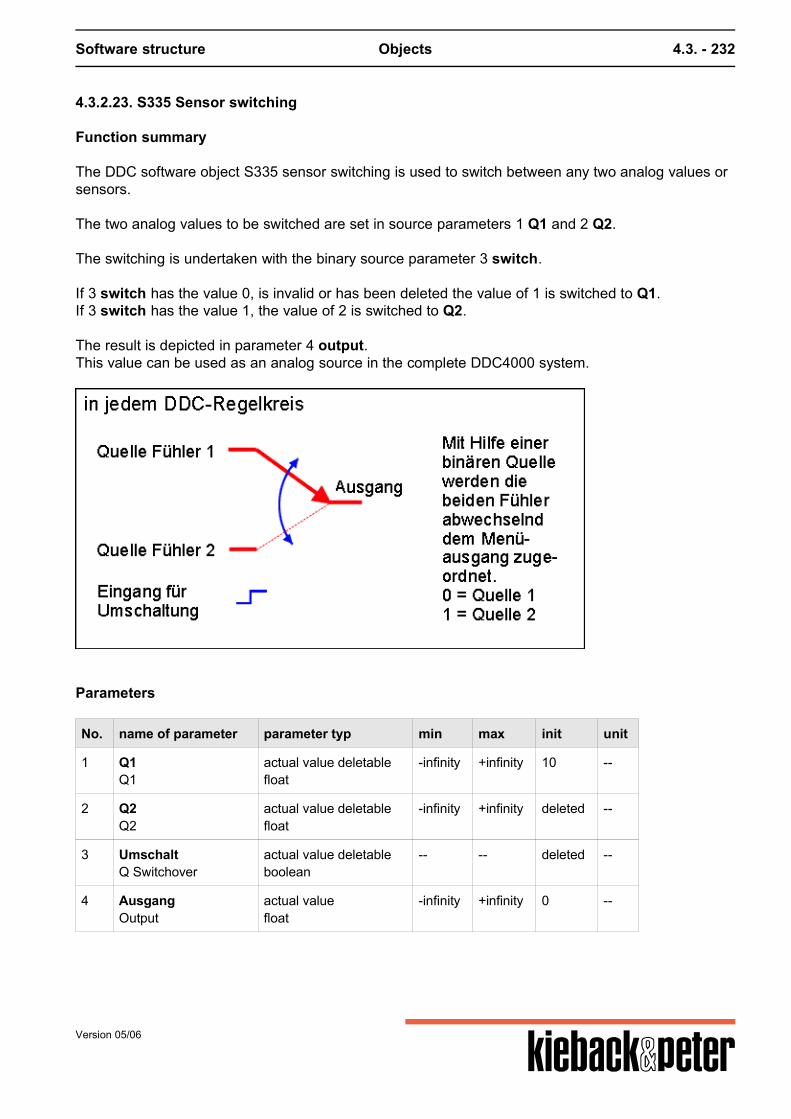
Software structure Objects 4.3. - 232
4.3.2.23. S335 Sensor switching
Function summary
The DDC software object S335 sensor switching is used to switch between any two analog values orsensors. The two analog values to be switched are set in source parameters 1 Q1 and 2 Q2. The switching is undertaken with the binary source parameter 3 switch. If 3 switch has the value 0, is invalid or has been deleted the value of 1 is switched to Q1.If 3 switch has the value 1, the value of 2 is switched to Q2. The result is depicted in parameter 4 output.This value can be used as an analog source in the complete DDC4000 system.
Parameters
No. name of parameter parameter typ min max init unit
1 Q1Q1
actual value deletablefloat
-infinity +infinity 10 --
2 Q2Q2
actual value deletablefloat
-infinity +infinity deleted --
3 UmschaltQ Switchover
actual value deletableboolean
-- -- deleted --
4 AusgangOutput
actual valuefloat
-infinity +infinity 0 --
Version 05/06
Software structure Objects 4.3. - 233
4.3.2.24. S337 Basic program fixed value
Activation
GP Fixed value can be installed up to 12 x
A PID regulator can be replaced by 4 fixed value regulators.
Function summary
The fixed value software object is a PI control with a sequence.
The fixed value regulator program is a PI regulator with a Y output. Other parameters are foradvanced functions, e.g.
- P regulator- Set point conversion- Set point glide- Y limitation- Y set.
Function description
The 5102 source control variable parameter can be assigned any analog value in the DDC4000system. The control can be switched between two set points, 5100 XS and 5107 XS2. The switchoccurs via the 5108 Q XS XS2 parameter that can be assigned any binary value. It also possible to glide the current set point according to any analog command value (e. g. theoutside temperature). The analog value is connected with the 5250 command value SG parameter.The set point gliding is calculated from the values for 5251 glide start SG, 5252 glide end SG and5253 EF SG, as per the set point glide functions described for the PID sub-menu. The effect of the fixed value control can be set to either heating or cooling via the 5124 Sequenceparameter. A binary source in 5129 Q sequence converter can also switch the effect of thesequence. The fixed value control works depending on the set reset time 5106 tN as a P or PI control. Theproportional range is set in the 5120 XPY1 parameter. The current Y value is indicated in the 5110 Y1 parameter. The Y output can be limited via 5141 Y1min and 5145 Y1 max. The Y output value calculated by the control unit can be overwritten by enforced intervention. This ispossible on the one hand via the setting for the value in 5324 Yfix. If the binary source in 5327 Q Y-Fix "1", the Y output is set to the Yfix value. Furthermore enforced setting is also possible via 5328 manual influence Y1 and 5329 analog BMSinfluence Y1.
Version 05/06
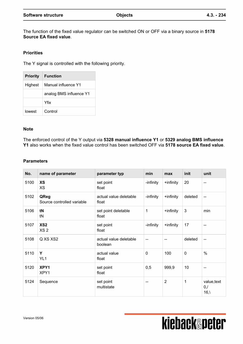
Software structure Objects 4.3. - 234
The function of the fixed value regulator can be switched ON or OFF via a binary source in 5178Source EA fixed value.
Priorities
The Y signal is controlled with the following priority.
Priority Function
Highest Manual influence Y1
analog BMS influence Y1
Yfix
lowest Control
Note
The enforced control of the Y output via 5328 manual influence Y1 or 5329 analog BMS influenceY1 also works when the fixed value control has been switched OFF via 5178 source EA fixed value.
Parameters
No. name of parameter parameter typ min max init unit
5100 XSXS
set pointfloat
-infinity +infinity 20 --
5102 QRegSource controlled variable
actual value deletablefloat
-infinity +infinity deleted --
5106 tNtN
set point deletablefloat
1 +infinity 3 min
5107 XS2XS 2
set pointfloat
-infinity +infinity 17 --
5108 Q XS XS2 actual value deletableboolean
-- -- deleted --
5110 YYL1
actual valuefloat
0 100 0 %
5120 XPY1XPY1
set pointfloat
0,5 999,9 10 --
5124 Sequence set pointmultistate
-- 2 1 value,text0,/16,\
Version 05/06
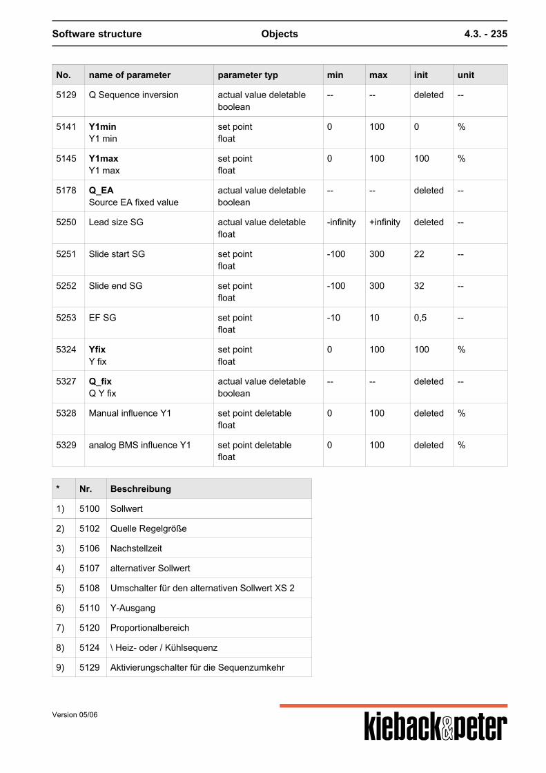
Software structure Objects 4.3. - 235
No. name of parameter parameter typ min max init unit
5129 Q Sequence inversion actual value deletableboolean
-- -- deleted --
5141 Y1minY1 min
set pointfloat
0 100 0 %
5145 Y1maxY1 max
set pointfloat
0 100 100 %
5178 Q_EASource EA fixed value
actual value deletableboolean
-- -- deleted --
5250 Lead size SG actual value deletablefloat
-infinity +infinity deleted --
5251 Slide start SG set pointfloat
-100 300 22 --
5252 Slide end SG set pointfloat
-100 300 32 --
5253 EF SG set pointfloat
-10 10 0,5 --
5324 YfixY fix
set pointfloat
0 100 100 %
5327 Q_fixQ Y fix
actual value deletableboolean
-- -- deleted --
5328 Manual influence Y1 set point deletablefloat
0 100 deleted %
5329 analog BMS influence Y1 set point deletablefloat
0 100 deleted %
* Nr. Beschreibung
1) 5100 Sollwert
2) 5102 Quelle Regelgröße
3) 5106 Nachstellzeit
4) 5107 alternativer Sollwert
5) 5108 Umschalter für den alternativen Sollwert XS 2
6) 5110 Y-Ausgang
7) 5120 Proportionalbereich
8) 5124 \ Heiz- oder / Kühlsequenz
9) 5129 Aktivierungschalter für die Sequenzumkehr
Version 05/06
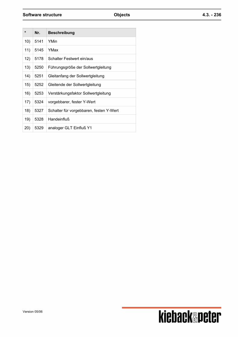
Software structure Objects 4.3. - 236
* Nr. Beschreibung
10) 5141 YMin
11) 5145 YMax
12) 5178 Schalter Festwert ein/aus
13) 5250 Führungsgröße der Sollwertgleitung
14) 5251 Gleitanfang der Sollwertgleitung
15) 5252 Gleitende der Sollwertgleitung
16) 5253 Verstärkungsfaktor Sollwertgleitung
17) 5324 vorgebbarer, fester Y-Wert
18) 5327 Schalter für vorgebbaren, festen Y-Wert
19) 5328 Handeinfluß
20) 5329 analoger GLT Einfluß Y1
Version 05/06
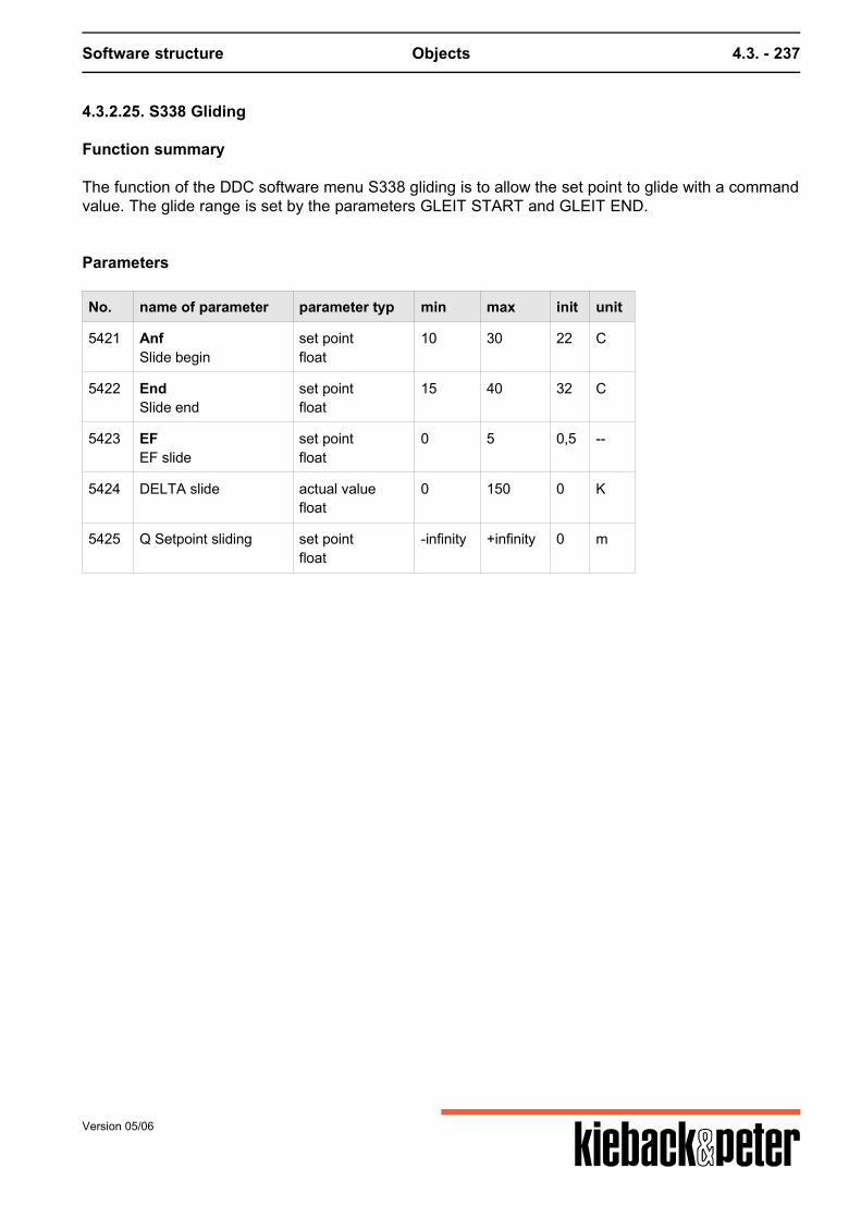
Software structure Objects 4.3. - 237
4.3.2.25. S338 Gliding
Function summary
The function of the DDC software menu S338 gliding is to allow the set point to glide with a commandvalue. The glide range is set by the parameters GLEIT START and GLEIT END.
Parameters
No. name of parameter parameter typ min max init unit
5421 AnfSlide begin
set pointfloat
10 30 22 C
5422 EndSlide end
set pointfloat
15 40 32 C
5423 EFEF slide
set pointfloat
0 5 0,5 --
5424 DELTA slide actual valuefloat
0 150 0 K
5425 Q Setpoint sliding set pointfloat
-infinity +infinity 0 m
Version 05/06
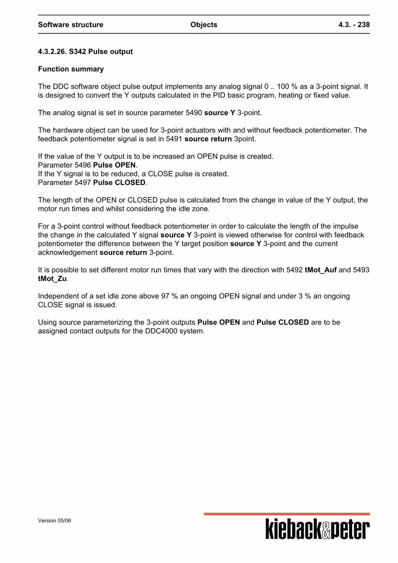
Software structure Objects 4.3. - 238
4.3.2.26. S342 Pulse output
Function summary
The DDC software object pulse output implements any analog signal 0 .. 100 % as a 3-point signal. Itis designed to convert the Y outputs calculated in the PID basic program, heating or fixed value. The analog signal is set in source parameter 5490 source Y 3-point. The hardware object can be used for 3-point actuators with and without feedback potentiometer. Thefeedback potentiometer signal is set in 5491 source return 3point. If the value of the Y output is to be increased an OPEN pulse is created.Parameter 5496 Pulse OPEN.If the Y signal is to be reduced, a CLOSE pulse is created.Parameter 5497 Pulse CLOSED. The length of the OPEN or CLOSED pulse is calculated from the change in value of the Y output, themotor run times and whilst considering the idle zone. For a 3-point control without feedback potentiometer in order to calculate the length of the impulsethe change in the calculated Y signal source Y 3-point is viewed otherwise for control with feedbackpotentiometer the difference between the Y target position source Y 3-point and the currentacknowledgement source return 3-point. It is possible to set different motor run times that vary with the direction with 5492 tMot_Auf and 5493tMot_Zu. Independent of a set idle zone above 97 % an ongoing OPEN signal and under 3 % an ongoingCLOSE signal is issued. Using source parameterizing the 3-point outputs Pulse OPEN and Pulse CLOSED are to beassigned contact outputs for the DDC4000 system.
Version 05/06
Software structure Objects 4.3. - 239
Parameters
No. name of parameter parameter typ min max init unit
5490 QSource Y 3 position
actual valuefloat
0 100 0 %
5491 Q RSource back 3 position
actual value deletablefloat
0 100 deleted %
5492 t AuftMot
set pointinteger
1 2147483647 180 s
5493 t ZutMot_Zu
set pointinteger
1 2147483647 180 s
5494 TotDead zone
set pointinteger
0 50 0 %
5496 AufImpulse OPEN
actual valueboolean
-- -- 0 --
5497 ZuImpulse SHUT
actual valueboolean
-- -- 0 --
Version 05/06
Software structure Objects 4.3. - 240
4.3.2.27. S343 E-Max
Function summary
The DDC software menu is used to switch off electrical consumers in a targeted manner. The aim isto keep the average electrical energy consumption of a building or technical plant under a stipulatedlimiting value. The software menu parameters can be set flexibly and permit the best possible changefor each specific problem and plants.
Parameters
No. name of parameter parameter typ min max init unit
5427 Q alarm reset set point deletableboolean
-- -- deleted --
5430 Limiting value high rate actual valuefloat
0,01 1000000 300 kW
5431 Limiting value low rate actual valuefloat
0,01 1000000 200 kW
5432 Q Limiting value rate actual value deletablereference
-- -- deleted --
5433 Impulse input actual value deletablereference
-- -- deleted --
5435 Scaling actual valuefloat
0 1000 1 --
5436 Scaling exp actual valueinteger
-4 4 1 --
5437 Q reset actual value deletablereference
-- -- deleted --
5440 Measuring cycle actual valueinteger
10 180 60 s
5441 Switch scale factor actual valueinteger
1 4 2 --
5442 Wait time actual valueinteger
0 5 3 --
5443 Measuring interval actual valueinteger
10 60 15 min
5444 Source OFF E max actual value deletablereference
-- -- deleted --
Version 05/06
Software structure Objects 4.3. - 241
No. name of parameter parameter typ min max init unit
5447 E max status set pointmultistate
-- 3 0 value,text0,No GW1,GW 12,GW 2
5448 E max alarm set pointboolean
-- -- 0 --
5450 max. nr. of consumers set pointinteger
0 20 0 --
5451 act. energy amount Z set pointfloat
0 10000000 0 kWh
5452 act. power Z set pointfloat
0 10000000 0 kW
5453 Trend power set pointfloat
0 10000000 0 kW
5455 P total set pointfloat
0 999999,875 0 kW
5456 P current set pointfloat
0 999999,875 0 kW
5457 P from set pointfloat
0 999999,875 0 kW
5487 P last measuring interval set pointfloat
0 10000000 0 kW
6641 Max. switched off time 1 actual valueinteger
5 60 60 min
6642 Max. switched off time 2 actual valueinteger
5 60 60 min
6643 Max. switched off time 3 actual valueinteger
5 60 60 min
6644 Max. switched off time 4 actual valueinteger
5 60 60 min
6645 Max. switched off time 5 actual valueinteger
5 60 60 min
6646 Max. switched off time 6 actual valueinteger
5 60 60 min
6647 Max. switched off time 7 actual valueinteger
5 60 60 min
6648 Max. switched off time 8 actual valueinteger
5 60 60 min
Version 05/06
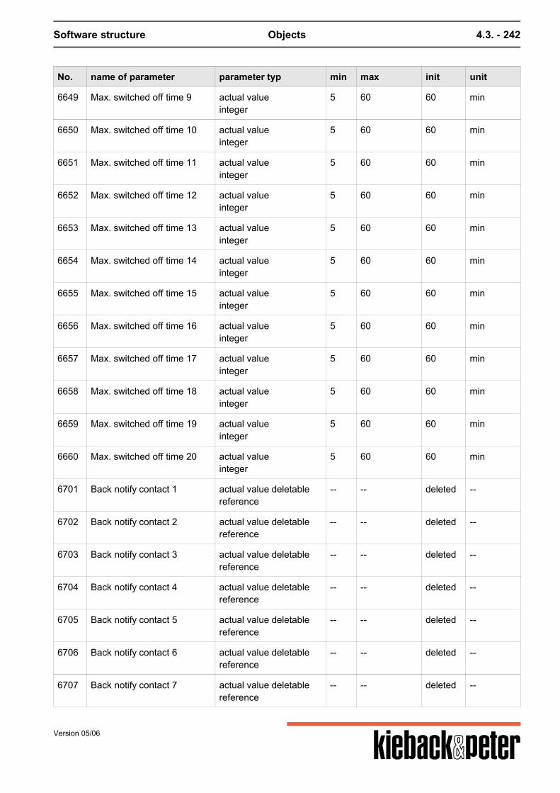
Software structure Objects 4.3. - 242
No. name of parameter parameter typ min max init unit
6649 Max. switched off time 9 actual valueinteger
5 60 60 min
6650 Max. switched off time 10 actual valueinteger
5 60 60 min
6651 Max. switched off time 11 actual valueinteger
5 60 60 min
6652 Max. switched off time 12 actual valueinteger
5 60 60 min
6653 Max. switched off time 13 actual valueinteger
5 60 60 min
6654 Max. switched off time 14 actual valueinteger
5 60 60 min
6655 Max. switched off time 15 actual valueinteger
5 60 60 min
6656 Max. switched off time 16 actual valueinteger
5 60 60 min
6657 Max. switched off time 17 actual valueinteger
5 60 60 min
6658 Max. switched off time 18 actual valueinteger
5 60 60 min
6659 Max. switched off time 19 actual valueinteger
5 60 60 min
6660 Max. switched off time 20 actual valueinteger
5 60 60 min
6701 Back notify contact 1 actual value deletablereference
-- -- deleted --
6702 Back notify contact 2 actual value deletablereference
-- -- deleted --
6703 Back notify contact 3 actual value deletablereference
-- -- deleted --
6704 Back notify contact 4 actual value deletablereference
-- -- deleted --
6705 Back notify contact 5 actual value deletablereference
-- -- deleted --
6706 Back notify contact 6 actual value deletablereference
-- -- deleted --
6707 Back notify contact 7 actual value deletablereference
-- -- deleted --
Version 05/06
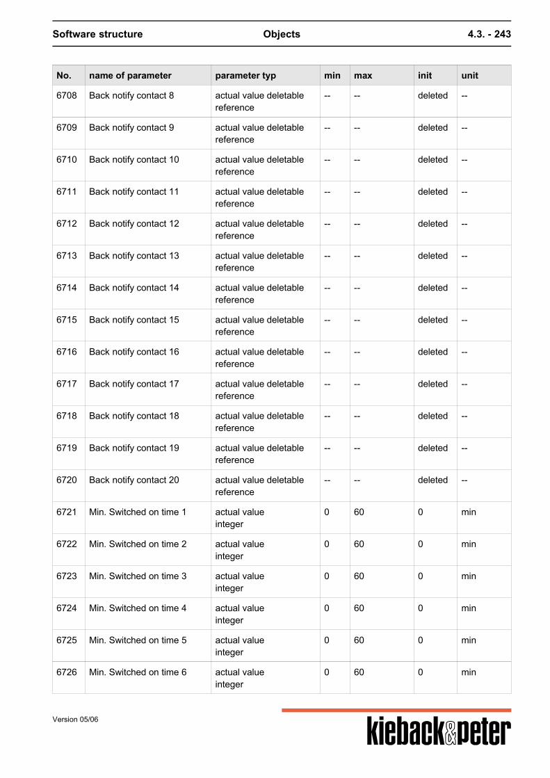
Software structure Objects 4.3. - 243
No. name of parameter parameter typ min max init unit
6708 Back notify contact 8 actual value deletablereference
-- -- deleted --
6709 Back notify contact 9 actual value deletablereference
-- -- deleted --
6710 Back notify contact 10 actual value deletablereference
-- -- deleted --
6711 Back notify contact 11 actual value deletablereference
-- -- deleted --
6712 Back notify contact 12 actual value deletablereference
-- -- deleted --
6713 Back notify contact 13 actual value deletablereference
-- -- deleted --
6714 Back notify contact 14 actual value deletablereference
-- -- deleted --
6715 Back notify contact 15 actual value deletablereference
-- -- deleted --
6716 Back notify contact 16 actual value deletablereference
-- -- deleted --
6717 Back notify contact 17 actual value deletablereference
-- -- deleted --
6718 Back notify contact 18 actual value deletablereference
-- -- deleted --
6719 Back notify contact 19 actual value deletablereference
-- -- deleted --
6720 Back notify contact 20 actual value deletablereference
-- -- deleted --
6721 Min. Switched on time 1 actual valueinteger
0 60 0 min
6722 Min. Switched on time 2 actual valueinteger
0 60 0 min
6723 Min. Switched on time 3 actual valueinteger
0 60 0 min
6724 Min. Switched on time 4 actual valueinteger
0 60 0 min
6725 Min. Switched on time 5 actual valueinteger
0 60 0 min
6726 Min. Switched on time 6 actual valueinteger
0 60 0 min
Version 05/06
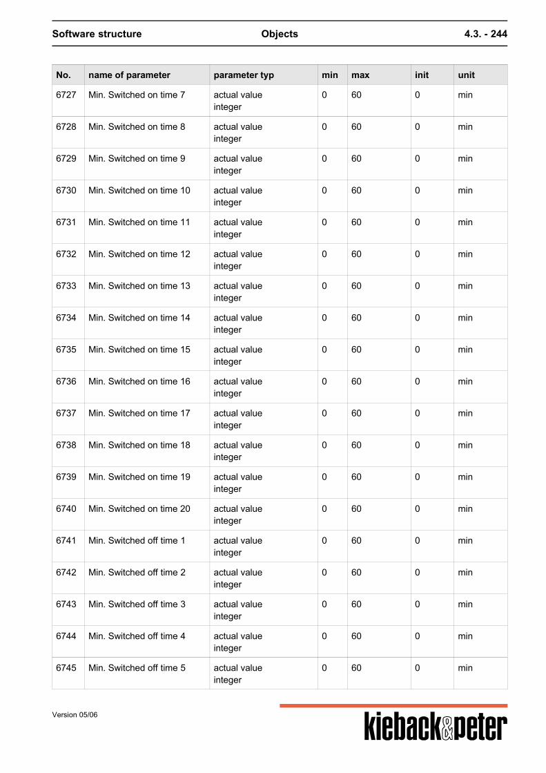
Software structure Objects 4.3. - 244
No. name of parameter parameter typ min max init unit
6727 Min. Switched on time 7 actual valueinteger
0 60 0 min
6728 Min. Switched on time 8 actual valueinteger
0 60 0 min
6729 Min. Switched on time 9 actual valueinteger
0 60 0 min
6730 Min. Switched on time 10 actual valueinteger
0 60 0 min
6731 Min. Switched on time 11 actual valueinteger
0 60 0 min
6732 Min. Switched on time 12 actual valueinteger
0 60 0 min
6733 Min. Switched on time 13 actual valueinteger
0 60 0 min
6734 Min. Switched on time 14 actual valueinteger
0 60 0 min
6735 Min. Switched on time 15 actual valueinteger
0 60 0 min
6736 Min. Switched on time 16 actual valueinteger
0 60 0 min
6737 Min. Switched on time 17 actual valueinteger
0 60 0 min
6738 Min. Switched on time 18 actual valueinteger
0 60 0 min
6739 Min. Switched on time 19 actual valueinteger
0 60 0 min
6740 Min. Switched on time 20 actual valueinteger
0 60 0 min
6741 Min. Switched off time 1 actual valueinteger
0 60 0 min
6742 Min. Switched off time 2 actual valueinteger
0 60 0 min
6743 Min. Switched off time 3 actual valueinteger
0 60 0 min
6744 Min. Switched off time 4 actual valueinteger
0 60 0 min
6745 Min. Switched off time 5 actual valueinteger
0 60 0 min
Version 05/06
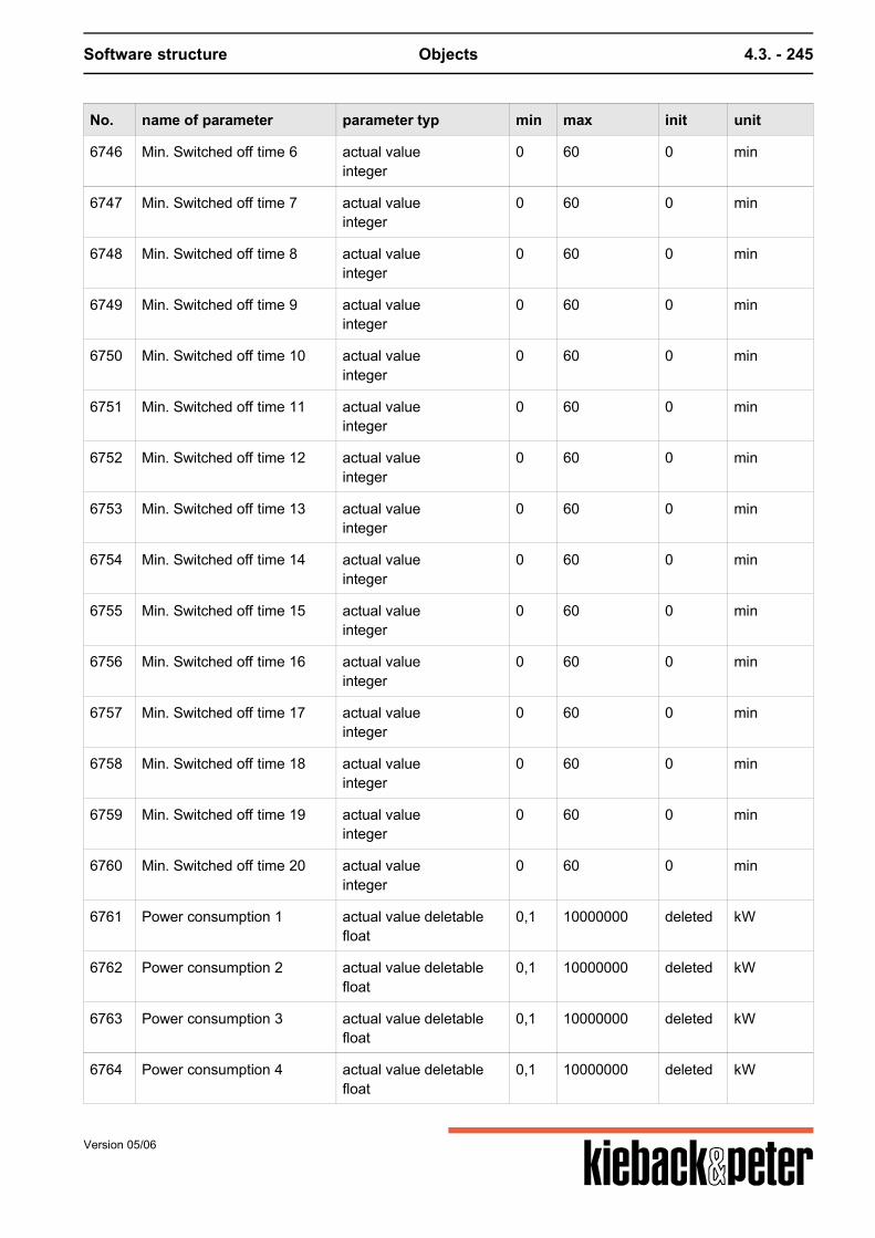
Software structure Objects 4.3. - 245
No. name of parameter parameter typ min max init unit
6746 Min. Switched off time 6 actual valueinteger
0 60 0 min
6747 Min. Switched off time 7 actual valueinteger
0 60 0 min
6748 Min. Switched off time 8 actual valueinteger
0 60 0 min
6749 Min. Switched off time 9 actual valueinteger
0 60 0 min
6750 Min. Switched off time 10 actual valueinteger
0 60 0 min
6751 Min. Switched off time 11 actual valueinteger
0 60 0 min
6752 Min. Switched off time 12 actual valueinteger
0 60 0 min
6753 Min. Switched off time 13 actual valueinteger
0 60 0 min
6754 Min. Switched off time 14 actual valueinteger
0 60 0 min
6755 Min. Switched off time 15 actual valueinteger
0 60 0 min
6756 Min. Switched off time 16 actual valueinteger
0 60 0 min
6757 Min. Switched off time 17 actual valueinteger
0 60 0 min
6758 Min. Switched off time 18 actual valueinteger
0 60 0 min
6759 Min. Switched off time 19 actual valueinteger
0 60 0 min
6760 Min. Switched off time 20 actual valueinteger
0 60 0 min
6761 Power consumption 1 actual value deletablefloat
0,1 10000000 deleted kW
6762 Power consumption 2 actual value deletablefloat
0,1 10000000 deleted kW
6763 Power consumption 3 actual value deletablefloat
0,1 10000000 deleted kW
6764 Power consumption 4 actual value deletablefloat
0,1 10000000 deleted kW
Version 05/06
Software structure Objects 4.3. - 246
No. name of parameter parameter typ min max init unit
6765 Power consumption 5 actual value deletablefloat
0,1 10000000 deleted kW
6766 Power consumption 6 actual value deletablefloat
0,1 10000000 deleted kW
6767 Power consumption 7 actual value deletablefloat
0,1 10000000 deleted kW
6768 Power consumption 8 actual value deletablefloat
0,1 10000000 deleted kW
6769 Power consumption 9 actual value deletablefloat
0,1 10000000 deleted kW
6770 Power consumption 10 actual value deletablefloat
0,1 10000000 deleted kW
6771 Power consumption 11 actual value deletablefloat
0,1 10000000 deleted kW
6772 Power consumption 12 actual value deletablefloat
0,1 10000000 deleted kW
6773 Power consumption 12 actual value deletablefloat
0,1 10000000 deleted kW
6774 Power consumption 14 actual value deletablefloat
0,1 10000000 deleted kW
6775 Power consumption 15 actual value deletablefloat
0,1 10000000 deleted kW
6776 Power consumption 16 actual value deletablefloat
0,1 10000000 deleted kW
6777 Power consumption 17 actual value deletablefloat
0,1 10000000 deleted kW
6778 Power consumption 18 actual value deletablefloat
0,1 10000000 deleted kW
6779 Power consumption 19 actual value deletablefloat
0,1 10000000 deleted kW
6780 Power consumption 20 actual value deletablefloat
0,1 10000000 deleted kW
6781 Priority 1 actual valueinteger
1 3 1 --
6782 Priority 2 actual valueinteger
1 3 1 --
6783 Priority 3 actual valueinteger
1 3 1 --
Version 05/06
Software structure Objects 4.3. - 247
No. name of parameter parameter typ min max init unit
6784 Priority 4 actual valueinteger
1 3 1 --
6785 Priority 5 actual valueinteger
1 3 1 --
6786 Priority 6 actual valueinteger
1 3 1 --
6787 Priority 7 actual valueinteger
1 3 1 --
6788 Priority 8 actual valueinteger
1 3 1 --
6789 Priority 9 actual valueinteger
1 3 1 --
6790 Priority 10 actual valueinteger
1 3 1 --
6791 Priority 11 actual valueinteger
1 3 1 --
6792 Priority 12 actual valueinteger
1 3 1 --
6793 Priority 13 actual valueinteger
1 3 1 --
6794 Priority 14 actual valueinteger
1 3 1 --
6795 Priority 15 actual valueinteger
1 3 1 --
6796 Priority 16 actual valueinteger
1 3 1 --
6797 Priority 17 actual valueinteger
1 3 1 --
6798 Priority 18 actual valueinteger
1 3 1 --
6799 Priority 19 actual valueinteger
1 3 1 --
6800 Priority 20 actual valueinteger
1 3 1 --
6801 Source Manual 1 actual value deletablereference
-- -- deleted --
6802 Source Manual 2 actual value deletablereference
-- -- deleted --
Version 05/06
Software structure Objects 4.3. - 248
No. name of parameter parameter typ min max init unit
6803 Source Manual 3 actual value deletablereference
-- -- deleted --
6804 Source Manual 4 actual value deletablereference
-- -- deleted --
6805 Source Manual 5 actual value deletablereference
-- -- deleted --
6806 Source Manual 6 actual value deletablereference
-- -- deleted --
6807 Source Manual 7 actual value deletablereference
-- -- deleted --
6808 Source Manual 8 actual value deletablereference
-- -- deleted --
6809 Source Manual 9 actual value deletablereference
-- -- deleted --
6810 Source Manual 10 actual value deletablereference
-- -- deleted --
6811 Source Manual 11 actual value deletablereference
-- -- deleted --
6812 Source Manual 12 actual value deletablereference
-- -- deleted --
6813 Source Manual 13 actual value deletablereference
-- -- deleted --
6814 Source Manual 14 actual value deletablereference
-- -- deleted --
6815 Source Manual 15 actual value deletablereference
-- -- deleted --
6816 Source Manual 16 actual value deletablereference
-- -- deleted --
6817 Source Manual 17 actual value deletablereference
-- -- deleted --
6818 Source Manual 18 actual value deletablereference
-- -- deleted --
6819 Source Manual 19 actual value deletablereference
-- -- deleted --
6820 Source Manual 20 actual value deletablereference
-- -- deleted --
6821 Consumers 1 set pointboolean
-- -- 1 --
Version 05/06

Software structure Objects 4.3. - 249
No. name of parameter parameter typ min max init unit
6822 Consumers 2 set pointboolean
-- -- 1 --
6823 Consumers 3 set pointboolean
-- -- 1 --
6824 Consumers 4 set pointboolean
-- -- 1 --
6825 Consumers 5 set pointboolean
-- -- 1 --
6826 Consumers 6 set pointboolean
-- -- 1 --
6827 Consumers 7 set pointboolean
-- -- 1 --
6828 Consumers 8 set pointboolean
-- -- 1 --
6829 Consumers 9 set pointboolean
-- -- 1 --
6830 Consumers 10 set pointboolean
-- -- 1 --
6831 Consumers 11 set pointboolean
-- -- 1 --
6832 Consumers 12 set pointboolean
-- -- 1 --
6833 Consumers 13 set pointboolean
-- -- 1 --
6834 Consumers 14 set pointboolean
-- -- 1 --
6835 Consumers 15 set pointboolean
-- -- 1 --
6836 Consumers 16 set pointboolean
-- -- 1 --
6837 Consumers 17 set pointboolean
-- -- 1 --
6838 Consumers 18 set pointboolean
-- -- 1 --
6839 Consumers 19 set pointboolean
-- -- 1 --
6840 Consumers 20 set pointboolean
-- -- 1 --
Version 05/06

Software structure Objects 4.3. - 250
Version 05/06
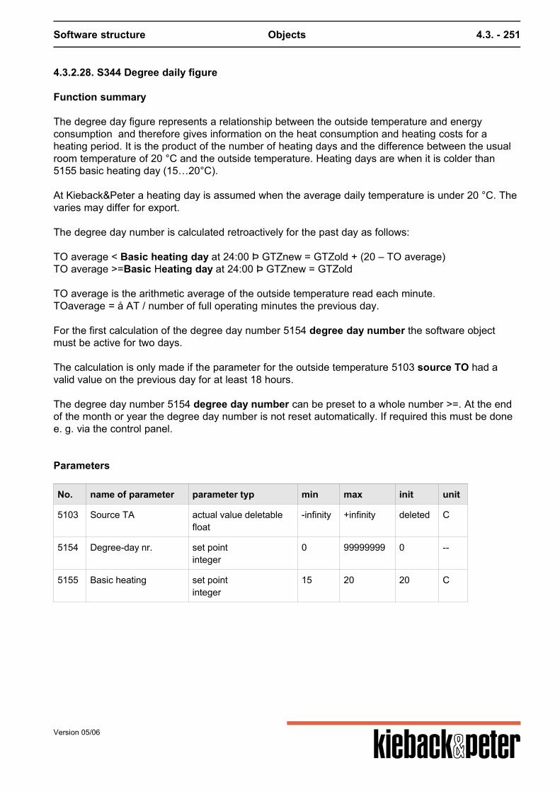
Software structure Objects 4.3. - 251
4.3.2.28. S344 Degree daily figure
Function summary
The degree day figure represents a relationship between the outside temperature and energyconsumption and therefore gives information on the heat consumption and heating costs for aheating period. It is the product of the number of heating days and the difference between the usualroom temperature of 20 °C and the outside temperature. Heating days are when it is colder than5155 basic heating day (15…20°C). At Kieback&Peter a heating day is assumed when the average daily temperature is under 20 °C. Thevaries may differ for export. The degree day number is calculated retroactively for the past day as follows: TO average < Basic heating day at 24:00 Þ GTZnew = GTZold + (20 – TO average)TO average >=Basic Heating day at 24:00 Þ GTZnew = GTZold TO average is the arithmetic average of the outside temperature read each minute.TOaverage = å AT / number of full operating minutes the previous day. For the first calculation of the degree day number 5154 degree day number the software objectmust be active for two days. The calculation is only made if the parameter for the outside temperature 5103 source TO had avalid value on the previous day for at least 18 hours. The degree day number 5154 degree day number can be preset to a whole number >=. At the endof the month or year the degree day number is not reset automatically. If required this must be donee. g. via the control panel.
Parameters
No. name of parameter parameter typ min max init unit
5103 Source TA actual value deletablefloat
-infinity +infinity deleted C
5154 Degree-day nr. set pointinteger
0 99999999 0 --
5155 Basic heating set pointinteger
15 20 20 C
Version 05/06
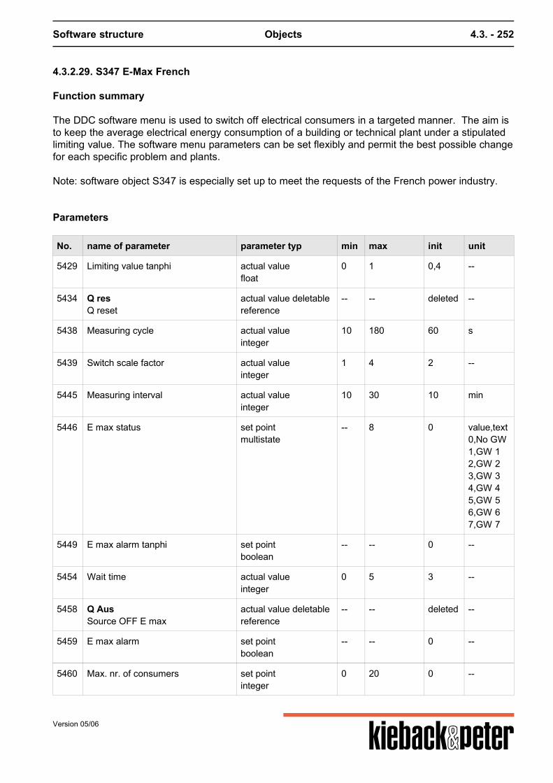
Software structure Objects 4.3. - 252
4.3.2.29. S347 E-Max French
Function summary
The DDC software menu is used to switch off electrical consumers in a targeted manner. The aim isto keep the average electrical energy consumption of a building or technical plant under a stipulatedlimiting value. The software menu parameters can be set flexibly and permit the best possible changefor each specific problem and plants. Note: software object S347 is especially set up to meet the requests of the French power industry.
Parameters
No. name of parameter parameter typ min max init unit
5429 Limiting value tanphi actual valuefloat
0 1 0,4 --
5434 Q resQ reset
actual value deletablereference
-- -- deleted --
5438 Measuring cycle actual valueinteger
10 180 60 s
5439 Switch scale factor actual valueinteger
1 4 2 --
5445 Measuring interval actual valueinteger
10 30 10 min
5446 E max status set pointmultistate
-- 8 0 value,text0,No GW1,GW 12,GW 23,GW 34,GW 45,GW 56,GW 67,GW 7
5449 E max alarm tanphi set pointboolean
-- -- 0 --
5454 Wait time actual valueinteger
0 5 3 --
5458 Q AusSource OFF E max
actual value deletablereference
-- -- deleted --
5459 E max alarm set pointboolean
-- -- 0 --
5460 Max. nr. of consumers set pointinteger
0 20 0 --
Version 05/06
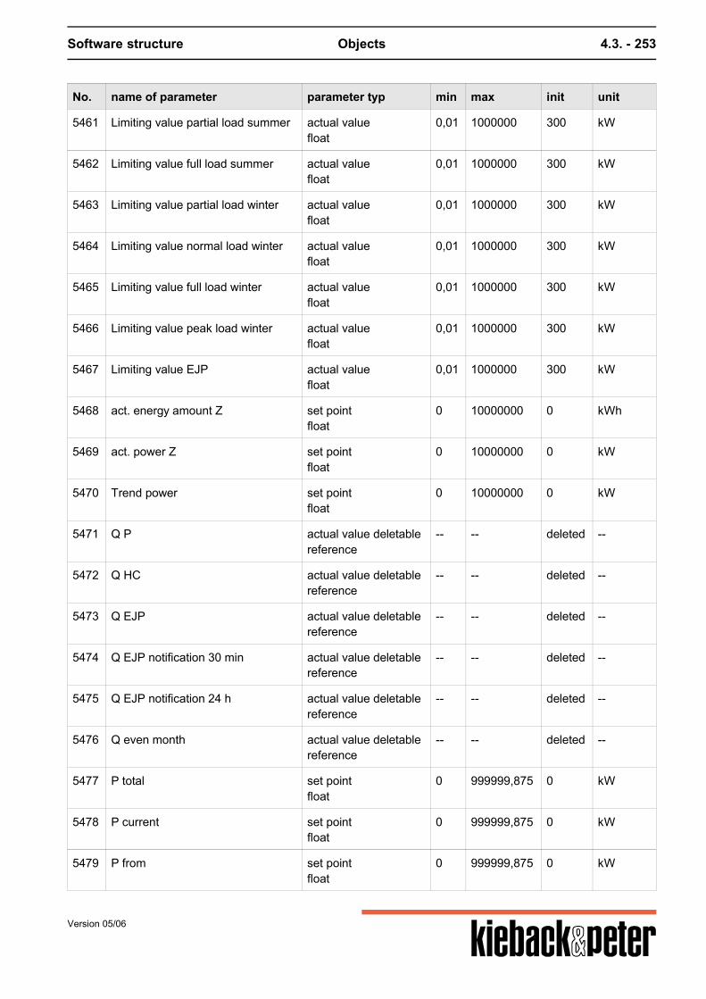
Software structure Objects 4.3. - 253
No. name of parameter parameter typ min max init unit
5461 Limiting value partial load summer actual valuefloat
0,01 1000000 300 kW
5462 Limiting value full load summer actual valuefloat
0,01 1000000 300 kW
5463 Limiting value partial load winter actual valuefloat
0,01 1000000 300 kW
5464 Limiting value normal load winter actual valuefloat
0,01 1000000 300 kW
5465 Limiting value full load winter actual valuefloat
0,01 1000000 300 kW
5466 Limiting value peak load winter actual valuefloat
0,01 1000000 300 kW
5467 Limiting value EJP actual valuefloat
0,01 1000000 300 kW
5468 act. energy amount Z set pointfloat
0 10000000 0 kWh
5469 act. power Z set pointfloat
0 10000000 0 kW
5470 Trend power set pointfloat
0 10000000 0 kW
5471 Q P actual value deletablereference
-- -- deleted --
5472 Q HC actual value deletablereference
-- -- deleted --
5473 Q EJP actual value deletablereference
-- -- deleted --
5474 Q EJP notification 30 min actual value deletablereference
-- -- deleted --
5475 Q EJP notification 24 h actual value deletablereference
-- -- deleted --
5476 Q even month actual value deletablereference
-- -- deleted --
5477 P total set pointfloat
0 999999,875 0 kW
5478 P current set pointfloat
0 999999,875 0 kW
5479 P from set pointfloat
0 999999,875 0 kW
Version 05/06
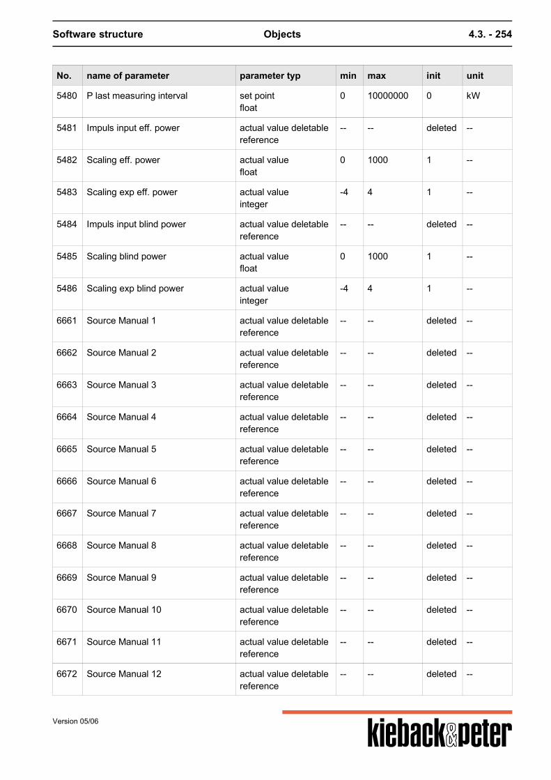
Software structure Objects 4.3. - 254
No. name of parameter parameter typ min max init unit
5480 P last measuring interval set pointfloat
0 10000000 0 kW
5481 Impuls input eff. power actual value deletablereference
-- -- deleted --
5482 Scaling eff. power actual valuefloat
0 1000 1 --
5483 Scaling exp eff. power actual valueinteger
-4 4 1 --
5484 Impuls input blind power actual value deletablereference
-- -- deleted --
5485 Scaling blind power actual valuefloat
0 1000 1 --
5486 Scaling exp blind power actual valueinteger
-4 4 1 --
6661 Source Manual 1 actual value deletablereference
-- -- deleted --
6662 Source Manual 2 actual value deletablereference
-- -- deleted --
6663 Source Manual 3 actual value deletablereference
-- -- deleted --
6664 Source Manual 4 actual value deletablereference
-- -- deleted --
6665 Source Manual 5 actual value deletablereference
-- -- deleted --
6666 Source Manual 6 actual value deletablereference
-- -- deleted --
6667 Source Manual 7 actual value deletablereference
-- -- deleted --
6668 Source Manual 8 actual value deletablereference
-- -- deleted --
6669 Source Manual 9 actual value deletablereference
-- -- deleted --
6670 Source Manual 10 actual value deletablereference
-- -- deleted --
6671 Source Manual 11 actual value deletablereference
-- -- deleted --
6672 Source Manual 12 actual value deletablereference
-- -- deleted --
Version 05/06
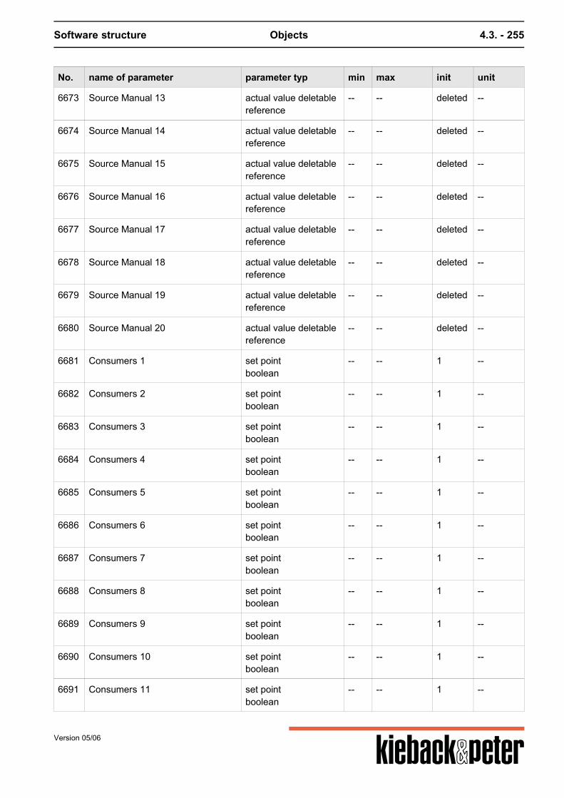
Software structure Objects 4.3. - 255
No. name of parameter parameter typ min max init unit
6673 Source Manual 13 actual value deletablereference
-- -- deleted --
6674 Source Manual 14 actual value deletablereference
-- -- deleted --
6675 Source Manual 15 actual value deletablereference
-- -- deleted --
6676 Source Manual 16 actual value deletablereference
-- -- deleted --
6677 Source Manual 17 actual value deletablereference
-- -- deleted --
6678 Source Manual 18 actual value deletablereference
-- -- deleted --
6679 Source Manual 19 actual value deletablereference
-- -- deleted --
6680 Source Manual 20 actual value deletablereference
-- -- deleted --
6681 Consumers 1 set pointboolean
-- -- 1 --
6682 Consumers 2 set pointboolean
-- -- 1 --
6683 Consumers 3 set pointboolean
-- -- 1 --
6684 Consumers 4 set pointboolean
-- -- 1 --
6685 Consumers 5 set pointboolean
-- -- 1 --
6686 Consumers 6 set pointboolean
-- -- 1 --
6687 Consumers 7 set pointboolean
-- -- 1 --
6688 Consumers 8 set pointboolean
-- -- 1 --
6689 Consumers 9 set pointboolean
-- -- 1 --
6690 Consumers 10 set pointboolean
-- -- 1 --
6691 Consumers 11 set pointboolean
-- -- 1 --
Version 05/06
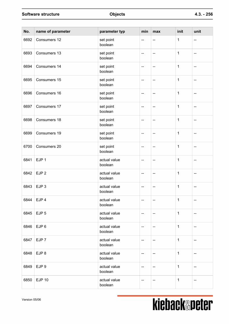
Software structure Objects 4.3. - 256
No. name of parameter parameter typ min max init unit
6692 Consumers 12 set pointboolean
-- -- 1 --
6693 Consumers 13 set pointboolean
-- -- 1 --
6694 Consumers 14 set pointboolean
-- -- 1 --
6695 Consumers 15 set pointboolean
-- -- 1 --
6696 Consumers 16 set pointboolean
-- -- 1 --
6697 Consumers 17 set pointboolean
-- -- 1 --
6698 Consumers 18 set pointboolean
-- -- 1 --
6699 Consumers 19 set pointboolean
-- -- 1 --
6700 Consumers 20 set pointboolean
-- -- 1 --
6841 EJP 1 actual valueboolean
-- -- 1 --
6842 EJP 2 actual valueboolean
-- -- 1 --
6843 EJP 3 actual valueboolean
-- -- 1 --
6844 EJP 4 actual valueboolean
-- -- 1 --
6845 EJP 5 actual valueboolean
-- -- 1 --
6846 EJP 6 actual valueboolean
-- -- 1 --
6847 EJP 7 actual valueboolean
-- -- 1 --
6848 EJP 8 actual valueboolean
-- -- 1 --
6849 EJP 9 actual valueboolean
-- -- 1 --
6850 EJP 10 actual valueboolean
-- -- 1 --
Version 05/06
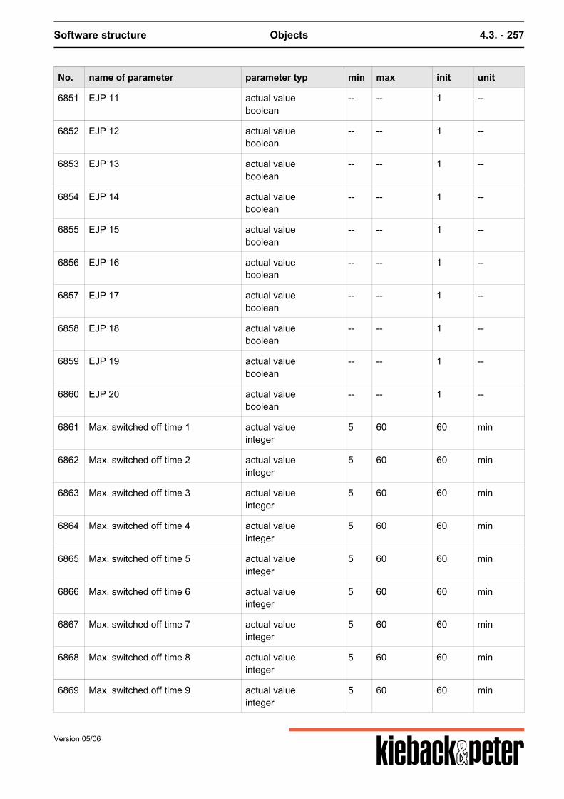
Software structure Objects 4.3. - 257
No. name of parameter parameter typ min max init unit
6851 EJP 11 actual valueboolean
-- -- 1 --
6852 EJP 12 actual valueboolean
-- -- 1 --
6853 EJP 13 actual valueboolean
-- -- 1 --
6854 EJP 14 actual valueboolean
-- -- 1 --
6855 EJP 15 actual valueboolean
-- -- 1 --
6856 EJP 16 actual valueboolean
-- -- 1 --
6857 EJP 17 actual valueboolean
-- -- 1 --
6858 EJP 18 actual valueboolean
-- -- 1 --
6859 EJP 19 actual valueboolean
-- -- 1 --
6860 EJP 20 actual valueboolean
-- -- 1 --
6861 Max. switched off time 1 actual valueinteger
5 60 60 min
6862 Max. switched off time 2 actual valueinteger
5 60 60 min
6863 Max. switched off time 3 actual valueinteger
5 60 60 min
6864 Max. switched off time 4 actual valueinteger
5 60 60 min
6865 Max. switched off time 5 actual valueinteger
5 60 60 min
6866 Max. switched off time 6 actual valueinteger
5 60 60 min
6867 Max. switched off time 7 actual valueinteger
5 60 60 min
6868 Max. switched off time 8 actual valueinteger
5 60 60 min
6869 Max. switched off time 9 actual valueinteger
5 60 60 min
Version 05/06
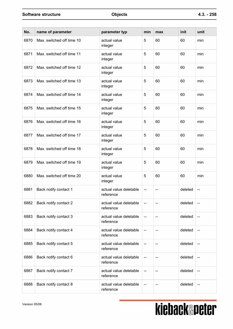
Software structure Objects 4.3. - 258
No. name of parameter parameter typ min max init unit
6870 Max. switched off time 10 actual valueinteger
5 60 60 min
6871 Max. switched off time 11 actual valueinteger
5 60 60 min
6872 Max. switched off time 12 actual valueinteger
5 60 60 min
6873 Max. switched off time 13 actual valueinteger
5 60 60 min
6874 Max. switched off time 14 actual valueinteger
5 60 60 min
6875 Max. switched off time 15 actual valueinteger
5 60 60 min
6876 Max. switched off time 16 actual valueinteger
5 60 60 min
6877 Max. switched off time 17 actual valueinteger
5 60 60 min
6878 Max. switched off time 18 actual valueinteger
5 60 60 min
6879 Max. switched off time 19 actual valueinteger
5 60 60 min
6880 Max. switched off time 20 actual valueinteger
5 60 60 min
6881 Back notify contact 1 actual value deletablereference
-- -- deleted --
6882 Back notify contact 2 actual value deletablereference
-- -- deleted --
6883 Back notify contact 3 actual value deletablereference
-- -- deleted --
6884 Back notify contact 4 actual value deletablereference
-- -- deleted --
6885 Back notify contact 5 actual value deletablereference
-- -- deleted --
6886 Back notify contact 6 actual value deletablereference
-- -- deleted --
6887 Back notify contact 7 actual value deletablereference
-- -- deleted --
6888 Back notify contact 8 actual value deletablereference
-- -- deleted --
Version 05/06
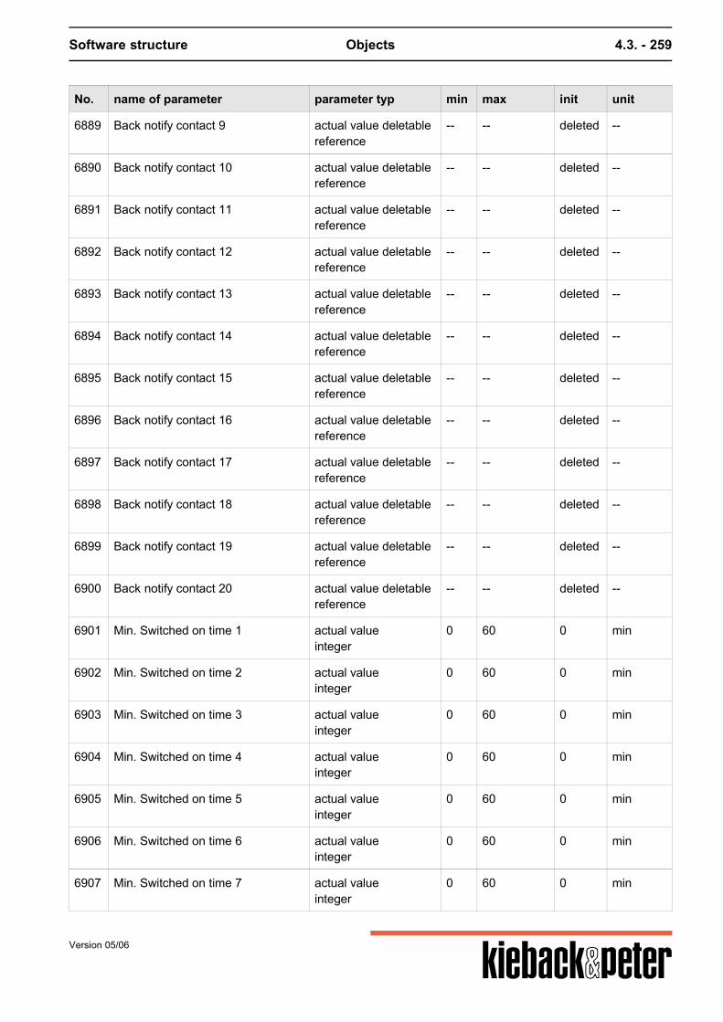
Software structure Objects 4.3. - 259
No. name of parameter parameter typ min max init unit
6889 Back notify contact 9 actual value deletablereference
-- -- deleted --
6890 Back notify contact 10 actual value deletablereference
-- -- deleted --
6891 Back notify contact 11 actual value deletablereference
-- -- deleted --
6892 Back notify contact 12 actual value deletablereference
-- -- deleted --
6893 Back notify contact 13 actual value deletablereference
-- -- deleted --
6894 Back notify contact 14 actual value deletablereference
-- -- deleted --
6895 Back notify contact 15 actual value deletablereference
-- -- deleted --
6896 Back notify contact 16 actual value deletablereference
-- -- deleted --
6897 Back notify contact 17 actual value deletablereference
-- -- deleted --
6898 Back notify contact 18 actual value deletablereference
-- -- deleted --
6899 Back notify contact 19 actual value deletablereference
-- -- deleted --
6900 Back notify contact 20 actual value deletablereference
-- -- deleted --
6901 Min. Switched on time 1 actual valueinteger
0 60 0 min
6902 Min. Switched on time 2 actual valueinteger
0 60 0 min
6903 Min. Switched on time 3 actual valueinteger
0 60 0 min
6904 Min. Switched on time 4 actual valueinteger
0 60 0 min
6905 Min. Switched on time 5 actual valueinteger
0 60 0 min
6906 Min. Switched on time 6 actual valueinteger
0 60 0 min
6907 Min. Switched on time 7 actual valueinteger
0 60 0 min
Version 05/06
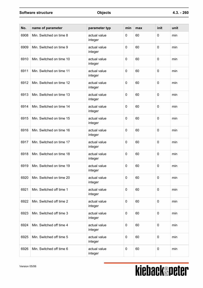
Software structure Objects 4.3. - 260
No. name of parameter parameter typ min max init unit
6908 Min. Switched on time 8 actual valueinteger
0 60 0 min
6909 Min. Switched on time 9 actual valueinteger
0 60 0 min
6910 Min. Switched on time 10 actual valueinteger
0 60 0 min
6911 Min. Switched on time 11 actual valueinteger
0 60 0 min
6912 Min. Switched on time 12 actual valueinteger
0 60 0 min
6913 Min. Switched on time 13 actual valueinteger
0 60 0 min
6914 Min. Switched on time 14 actual valueinteger
0 60 0 min
6915 Min. Switched on time 15 actual valueinteger
0 60 0 min
6916 Min. Switched on time 16 actual valueinteger
0 60 0 min
6917 Min. Switched on time 17 actual valueinteger
0 60 0 min
6918 Min. Switched on time 18 actual valueinteger
0 60 0 min
6919 Min. Switched on time 19 actual valueinteger
0 60 0 min
6920 Min. Switched on time 20 actual valueinteger
0 60 0 min
6921 Min. Switched off time 1 actual valueinteger
0 60 0 min
6922 Min. Switched off time 2 actual valueinteger
0 60 0 min
6923 Min. Switched off time 3 actual valueinteger
0 60 0 min
6924 Min. Switched off time 4 actual valueinteger
0 60 0 min
6925 Min. Switched off time 5 actual valueinteger
0 60 0 min
6926 Min. Switched off time 6 actual valueinteger
0 60 0 min
Version 05/06
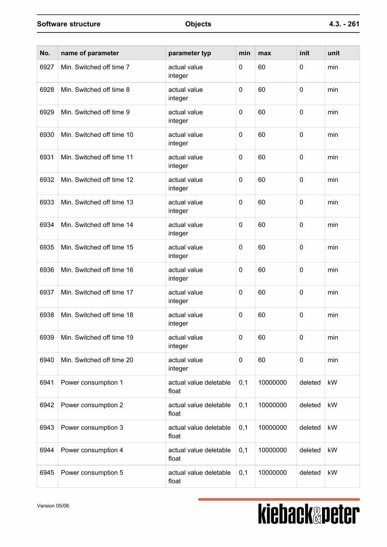
Software structure Objects 4.3. - 261
No. name of parameter parameter typ min max init unit
6927 Min. Switched off time 7 actual valueinteger
0 60 0 min
6928 Min. Switched off time 8 actual valueinteger
0 60 0 min
6929 Min. Switched off time 9 actual valueinteger
0 60 0 min
6930 Min. Switched off time 10 actual valueinteger
0 60 0 min
6931 Min. Switched off time 11 actual valueinteger
0 60 0 min
6932 Min. Switched off time 12 actual valueinteger
0 60 0 min
6933 Min. Switched off time 13 actual valueinteger
0 60 0 min
6934 Min. Switched off time 14 actual valueinteger
0 60 0 min
6935 Min. Switched off time 15 actual valueinteger
0 60 0 min
6936 Min. Switched off time 16 actual valueinteger
0 60 0 min
6937 Min. Switched off time 17 actual valueinteger
0 60 0 min
6938 Min. Switched off time 18 actual valueinteger
0 60 0 min
6939 Min. Switched off time 19 actual valueinteger
0 60 0 min
6940 Min. Switched off time 20 actual valueinteger
0 60 0 min
6941 Power consumption 1 actual value deletablefloat
0,1 10000000 deleted kW
6942 Power consumption 2 actual value deletablefloat
0,1 10000000 deleted kW
6943 Power consumption 3 actual value deletablefloat
0,1 10000000 deleted kW
6944 Power consumption 4 actual value deletablefloat
0,1 10000000 deleted kW
6945 Power consumption 5 actual value deletablefloat
0,1 10000000 deleted kW
Version 05/06
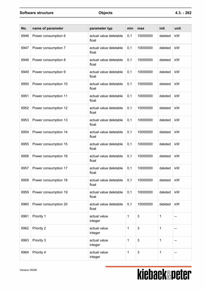
Software structure Objects 4.3. - 262
No. name of parameter parameter typ min max init unit
6946 Power consumption 6 actual value deletablefloat
0,1 10000000 deleted kW
6947 Power consumption 7 actual value deletablefloat
0,1 10000000 deleted kW
6948 Power consumption 8 actual value deletablefloat
0,1 10000000 deleted kW
6949 Power consumption 9 actual value deletablefloat
0,1 10000000 deleted kW
6950 Power consumption 10 actual value deletablefloat
0,1 10000000 deleted kW
6951 Power consumption 11 actual value deletablefloat
0,1 10000000 deleted kW
6952 Power consumption 12 actual value deletablefloat
0,1 10000000 deleted kW
6953 Power consumption 13 actual value deletablefloat
0,1 10000000 deleted kW
6954 Power consumption 14 actual value deletablefloat
0,1 10000000 deleted kW
6955 Power consumption 15 actual value deletablefloat
0,1 10000000 deleted kW
6956 Power consumption 16 actual value deletablefloat
0,1 10000000 deleted kW
6957 Power consumption 17 actual value deletablefloat
0,1 10000000 deleted kW
6958 Power consumption 18 actual value deletablefloat
0,1 10000000 deleted kW
6959 Power consumption 19 actual value deletablefloat
0,1 10000000 deleted kW
6960 Power consumption 20 actual value deletablefloat
0,1 10000000 deleted kW
6961 Priority 1 actual valueinteger
1 3 1 --
6962 Priority 2 actual valueinteger
1 3 1 --
6963 Priority 3 actual valueinteger
1 3 1 --
6964 Priority 4 actual valueinteger
1 3 1 --
Version 05/06
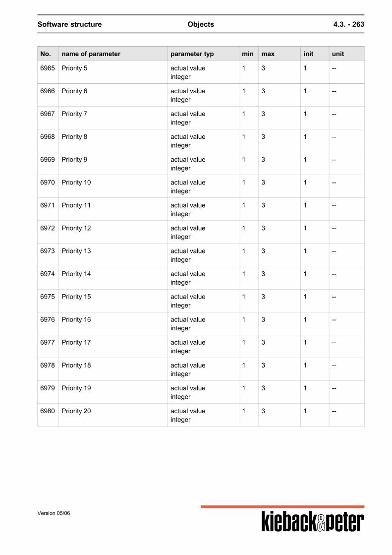
Software structure Objects 4.3. - 263
No. name of parameter parameter typ min max init unit
6965 Priority 5 actual valueinteger
1 3 1 --
6966 Priority 6 actual valueinteger
1 3 1 --
6967 Priority 7 actual valueinteger
1 3 1 --
6968 Priority 8 actual valueinteger
1 3 1 --
6969 Priority 9 actual valueinteger
1 3 1 --
6970 Priority 10 actual valueinteger
1 3 1 --
6971 Priority 11 actual valueinteger
1 3 1 --
6972 Priority 12 actual valueinteger
1 3 1 --
6973 Priority 13 actual valueinteger
1 3 1 --
6974 Priority 14 actual valueinteger
1 3 1 --
6975 Priority 15 actual valueinteger
1 3 1 --
6976 Priority 16 actual valueinteger
1 3 1 --
6977 Priority 17 actual valueinteger
1 3 1 --
6978 Priority 18 actual valueinteger
1 3 1 --
6979 Priority 19 actual valueinteger
1 3 1 --
6980 Priority 20 actual valueinteger
1 3 1 --
Version 05/06
Software structure Objects 4.3. - 264
4.3.2.30. S901 Signal generator
Function summary
Signal generator for test purposes. Produces a- sinus signal- Ramp / sawtooth signal- Rectangular signal
with selectable- period duration- Amplitude- Amplitude offsetThe cycle time of the signal generator is 50ms. All three different signal generators have a reset inputthat restarts the production of the output signal. Functions / restrictions:- Sinus generator: minimum period duration > 10* cycle time- Ramp / sawtooth signal: t1: Time for increasing ramp >= cycle time t2: Time for falling ramp, >= cycle time, connected to t1 t1+t2 must be <= period time if t1+t2 < period time the signal looks like this: /\_/\_- Rectangular generator: tPulse: "On" pulse time must be > cycle time and < period time.
Parameters
No. name of parameter parameter typ min max init unit
1 tPer_sinT_Periode_Sinus
set pointfloat
1 +infinity 10 s
2 Half_Ampl_sin set pointfloat
0 +infinity 1 --
3 Offs_sin set pointfloat
-infinity +infinity 0 --
4 Res SinReset_sin
set pointboolean
-- -- 0 --
5 tPer_ramp set pointfloat
1 +infinity 10 s
6 t1_ramp set pointfloat
0,1 +infinity 9,9 s
7 t2_ramp set pointfloat
0,1 +infinity 0,1 s
Version 05/06
Software structure Objects 4.3. - 265
No. name of parameter parameter typ min max init unit
8 Ampl_ramp set pointfloat
0 +infinity 1 --
9 Offs_ramp set pointfloat
-infinity +infinity 0 --
10 res rampReset_ramp
set pointboolean
-- -- 0 --
11 tPer_pulse set pointfloat
0,1 +infinity 1 s
12 tPulse_pulse set pointfloat
0,05 +infinity 0,5 s
13 Ampl_pulse set pointfloat
0 +infinity 1 --
14 Offs_pulse set pointfloat
-infinity +infinity 0 --
15 Reset_pulse set pointboolean
-- -- 0 --
16 sinsine
actual valuefloat
-infinity +infinity 0 --
17 ramperamp
actual valuefloat
-infinity +infinity 0 --
18 Impulspulse
actual valuefloat
-infinity +infinity 0 --
19 tcycCycle time
actual valuefloat
0,01 3600 1 s
Version 05/06
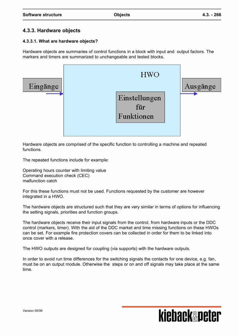
Software structure Objects 4.3. - 266
4.3.3. Hardware objects
4.3.3.1. What are hardware objects?
Hardware objects are summaries of control functions in a block with input and output factors. Themarkers and timers are summarized to unchangeable and tested blocks.
Hardware objects are comprised of the specific function to controlling a machine and repeatedfunctions. The repeated functions include for example: Operating hours counter with limiting valueCommand execution check (CEC)malfunction catch For this these functions must not be used. Functions requested by the customer are howeverintegrated in a HWO. The hardware objects are structured such that they are very similar in terms of options for influencingthe setting signals, priorities and function groups.
The hardware objects receive their input signals from the control, from hardware inputs or the DDCcontrol (markers, timer). With the aid of the DDC market and time missing functions on these HWOscan be set. For example fire protection covers can be collected in order for them to be linked intoonce cover with a release. The HWO outputs are designed for coupling (via supports) with the hardware outputs. In order to avoid run time differences for the switching signals the contacts for one device, e.g. fan,must be on an output module. Otherwise the steps or on and off signals may take place at the sametime.
Version 05/06
Software structure Objects 4.3. - 267
Parameters, names and classification
Parameters can be addressed in two different ways.1. via the parameter number and 2. via the parameter name.The parameter number is unique to only one object. Each object can have for example a parameterwith the number 12 and the text "Rep". For this addressing is possible in sources and links both viavoice-led parameters and via parameter names. The use of texts instead of numbers isadvantageous for planning plant assignments and when reading sources. A customer-specific plain text can still be set for the relevant parameter.
There are different types of parameters:
Binary values (Boolean): Logical value (0 or 1) Integer: Number without places after decimal point (-2,147,483,648 to +2,147,483,647 ) Floating comma: Number with digits after the decimal point (-3.402823466E38 to
3.402823466E38) Multistate: Value has one of several statuses (0-OFF, 1-ON, 9-AUTO). For this "BACnet" in the
parameter table means the BACnet number of the status and "DDC No." means the DDC4000number.
Selection list: Value that can have one of a choice of statuses. Each status is one bit position.
Version 05/06
Software structure Objects 4.3. - 268
4.3.3.2. All hardware objects
object no. name of object releasestage: 24.07.2006
H000S Sim unreleased
H001 Circul. pump 0.3.33
H002 Pump 0.3.33
H004 Device on the M-Bus 0.2.1
H010 Network-Var. unreleased
H045 Control channel unreleased
H101 Sensor general unreleased
H102 Sensor pressure unreleased
H103 Sensor humidity unreleased
H104 Sensor CO2 unreleased
H105 Sensor temperature unreleased
H106 Sensor volume current unreleased
H201 Detector general unreleased
H202 Detector diff pressure ventilator unreleased
H203 Detector frost protection unreleased
H204 Detector STB/TR unreleased
H301 Steam humidifier cont. 0.1.9
H302 Steam humidif. constant unreleased
H401 One-level electro heater 0.1.9
H402 Two-level electro heater 0.1.9
H403 Three-level electro heater 0.1.9
H404 Electroheater contin. 0.1.9
H501 Flap OPEN/SHUT 0.1.9
H502 Fire protection flap 0.1.9
H503 Flap 3-Point 0.1.9
H504 Flap continuous 0.1.9
H601 1-level fan 0.1.9
H602 2-level fan 0.1.9
Version 05/06
Software structure Objects 4.3. - 269
object no. name of object releasestage: 24.07.2006
H603 3-level fan unreleased
H604 Fan FU/Byp 0.1.9
H611 Valve OPEN/SHUT 0.1.9
H612 Valve BUS unreleased
H613 3-point valve 0.1.9
H614 Valve cont. 0.1.9
H701 One-level burner 0.1.9
H702 Two-level burner 0.1.9
H703 Burner modulat. 3-point 0.1.9
H704 Burner cont. modulating 0.1.9
H801 Volume current controller const 0.1.9
H802 Volume current controller cont. 0.1.9
H901 One level pump 0.1.9
H903 Pump FU/Bypass 0.1.9
H904 Pump BUS unreleased
H905 Double pump 0.1.9
Version 05/06
Software structure Objects 4.3. - 270
4.3.3.3. Priorities and signals
Priorities auto, Z, DOL, manual, forced and malfunction
There are various options for influencing the setting signals. Setting signals are changed in the various hardware objects be the following intervention variable:
Priority Parameter / Value Action
Highest SM Described in the relevant "trouble-shooting" section, usually switch offoutputs
Rep, Zw/Off, Manual/Off Switch off outputs
Manual/open, Zw/open Switch on outputs
Z/closed, DOL Switch off outputs
Z/On Switch on outputs
lowest Auto Automatic operation
SM Malfunction message from the field
Rep Repair switch - influences a block released on the device for repair work
Zw Forced influence - intervention through regulating or control events, e.g. to integrate superordinatemalfunction messages such as frost guards (forced on, forced off or forced values)
Manual Manual influence - Intervention through operation on / near the DDC (manual on, manual off, manualautomatic etc) or manual values
Z Z influence - intervention by switching on building technology (Z on, Z off)
Auto Automatic operation, if nec. by influencing time programs
DOL Direct operating level - intervention through direct operation (e.g. front switch modules)
Most of the abbreviations above and following are refering to German expressions therefore they arenot reasonable for English understanding.
Version 05/06
Software structure Objects 4.3. - 271
4.3.3.4. Command execution check CEC
Command execution check
The command execution control is used to monitor binary operating actual statuses.An actual operation status (or operating message) must with a specific period of time tCEC matchthe value of a target operating status, otherwise the binary output stCEC is set to 1. If the actualoperating status is not switched no stCEC is signaled.The stCEC is reset when the ResSM input changes from 0 to 1.If the ResCEC input is not switched stCEC is reset when the actual operating status matches thetarget operating status again.The 0/1 flank from stCEC is out put with a VzCEC delay. The monitored signal is withdrawn for malfunction recognition after the time tCEC + VzCEC.
Par.No Parameter name, plain text Description Input Ed.
Bsz Input target operational status x
CEC Input for the binary actual status x
tCEC Time within which the actual operating status may differfrom the target operating status without releasing stCEC
x
VzCEC stCEC is output with a delay for the stated time. x
ResCEC Resets the stCEC. x
stCEC Signals that the actual operating status was longer thanthe tCEC of the target operating status.
x
Signal interaction depiction
Version 05/06
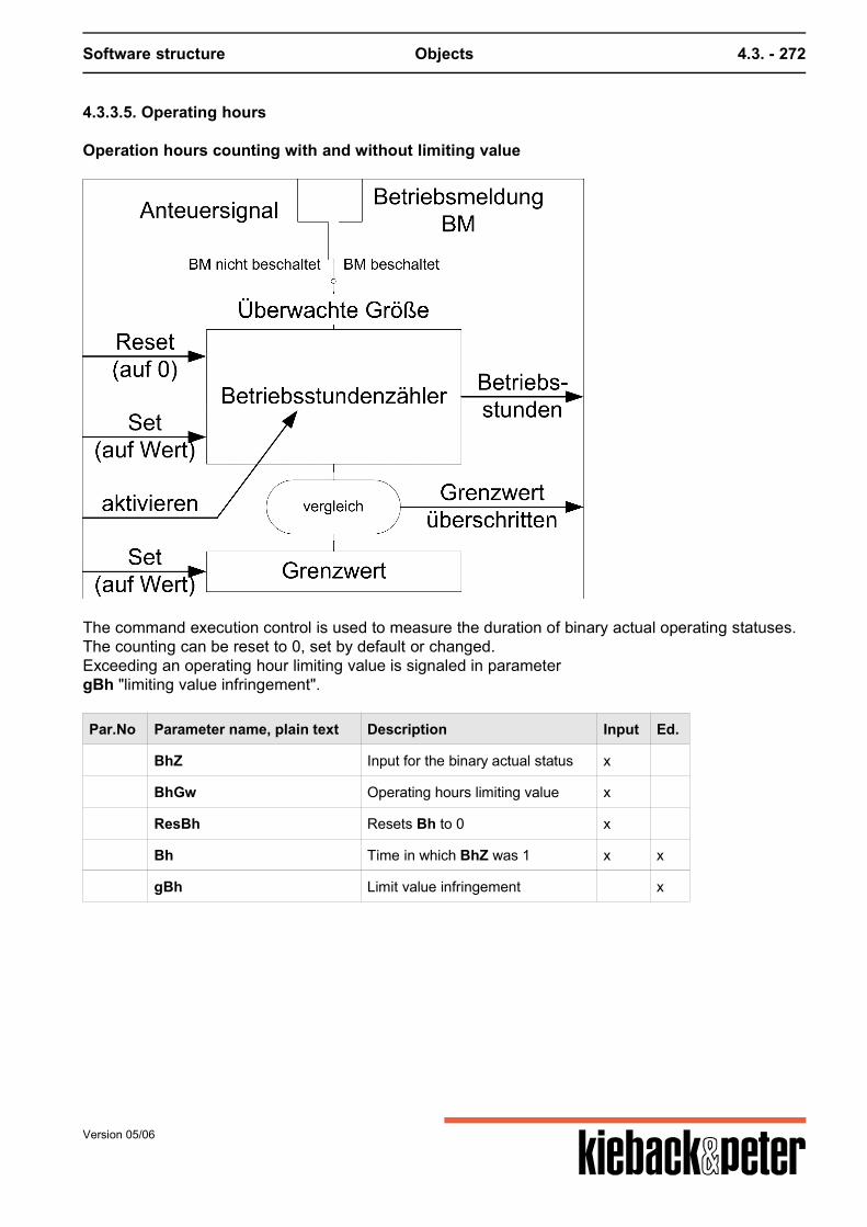
Software structure Objects 4.3. - 272
4.3.3.5. Operating hours
Operation hours counting with and without limiting value
The command execution control is used to measure the duration of binary actual operating statuses.The counting can be reset to 0, set by default or changed.Exceeding an operating hour limiting value is signaled in parametergBh "limiting value infringement".
Par.No Parameter name, plain text Description Input Ed.
BhZ Input for the binary actual status x
BhGw Operating hours limiting value x
ResBh Resets Bh to 0 x
Bh Time in which BhZ was 1 x x
gBh Limit value infringement x
Version 05/06
Software structure Objects 4.3. - 273
4.3.3.6. Malfunction catch
A set malfunction message signal prevents the occurrence of a new malfunction message. A malfunction that occurs SM may influence the control of output Ya) not ("malfunction blocked" = 0)b) sets the Y output to 0% or for binary outputs to 0 and if nec. Anf to 0 ("malfunction blocked" = 1) The malfunction message can be reset with "ResSM". An important note:How does "malfunction blocked" work? The "malfunction blocked" parameter can be set to yes or no. If a malfunction occurs either theoutput is switched off or the malfunction does not affect the outputs. The malfunction catch is activated by linking a source on ResSM (Reset malfunction message).Only in this case is it possible to reset a malfunction message. Here a link creates a function.
Parameters
Parameter name, plain text Description Input Ed.
Reset is controlled by level indicator
Version 05/06
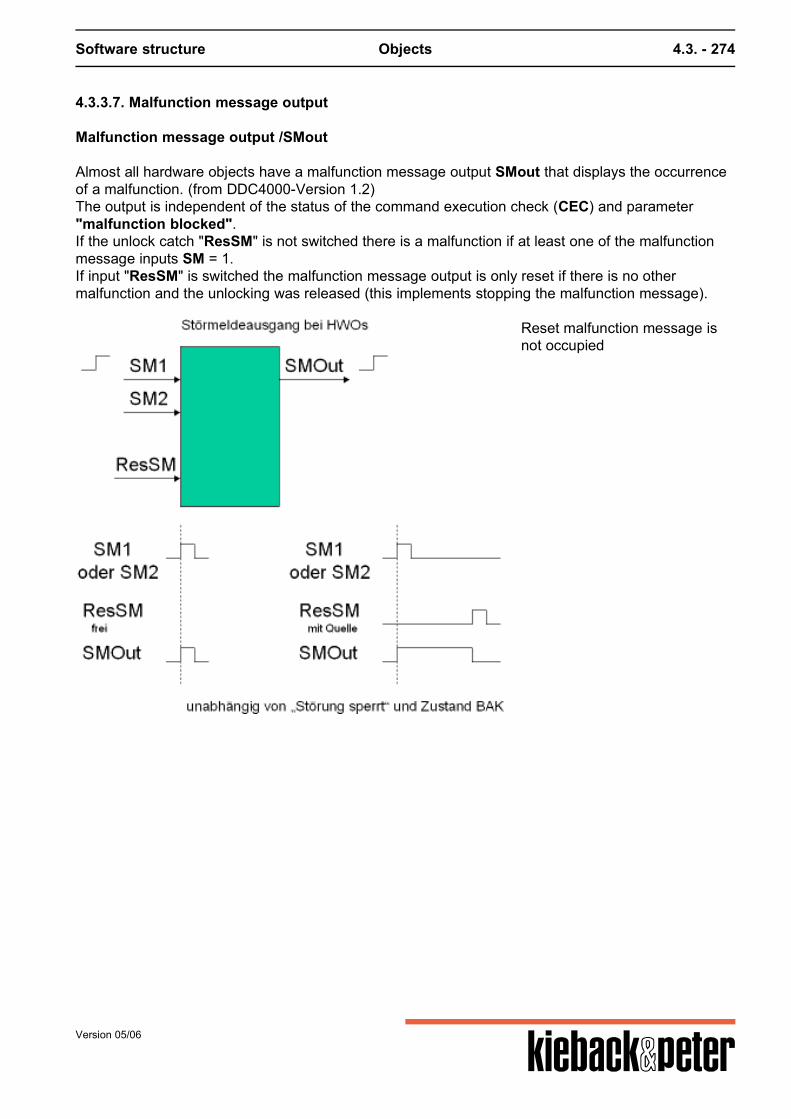
Software structure Objects 4.3. - 274
4.3.3.7. Malfunction message output
Malfunction message output /SMout
Almost all hardware objects have a malfunction message output SMout that displays the occurrenceof a malfunction. (from DDC4000-Version 1.2)The output is independent of the status of the command execution check (CEC) and parameter"malfunction blocked".If the unlock catch "ResSM" is not switched there is a malfunction if at least one of the malfunctionmessage inputs SM = 1.If input "ResSM" is switched the malfunction message output is only reset if there is no othermalfunction and the unlocking was released (this implements stopping the malfunction message).
Reset malfunction message isnot occupied
Version 05/06
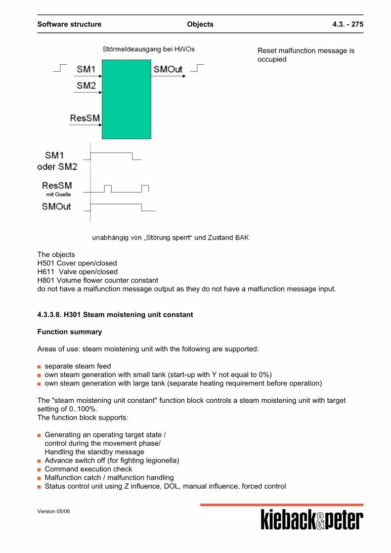
Software structure Objects 4.3. - 275
Reset malfunction message isoccupied
The objectsH501 Cover open/closedH611 Valve open/closedH801 Volume flower counter constantdo not have a malfunction message output as they do not have a malfunction message input.
4.3.3.8. H301 Steam moistening unit constant
Function summary
Areas of use: steam moistening unit with the following are supported:
separate steam feed own steam generation with small tank (start-up with Y not equal to 0%) own steam generation with large tank (separate heating requirement before operation)
The "steam moistening unit constant" function block controls a steam moistening unit with targetsetting of 0..100%.The function block supports:
Generating an operating target state /control during the movement phase/Handling the standby message
Advance switch off (for fighting legionella) Command execution check Malfunction catch / malfunction handling Status control unit using Z influence, DOL, manual influence, forced control
Version 05/06
Software structure Objects 4.3. - 276
Parameters
No. name of parameter parameter typ min max init unit
1 AnfAutoBeg. Automatic
actual value deletableboolean
-- -- deleted --
2 YsollSetpoint.Autom
set pointfloat
0 100 50 %
3 GwYsollLimitval.Yset
set pointfloat
0 100 3 %
4 VorabAdvance switch off
actual value deletableboolean
-- -- deleted --
5 BMOperation
actual value deletableboolean
-- -- deleted --
6 BereitReady
actual value deletableboolean
-- -- deleted --
7 tBAKtBAK
set pointfloat
0 +infinity 30 s
8 VzBAKVzBAK
set pointfloat
0 +infinity 20 s
9 SMSM
actual value deletableboolean
-- -- deleted --
10 ResSMResSM
actual value deletableboolean
-- -- deleted --
11 StSperrSM blocked
set pointboolean
-- -- 0 --
12 ZZ- influence
set point deletablefloat
0 100 deleted %
13 RepRep.switch
actual value deletableboolean
-- -- deleted --
14 HandManual
actual value deletablefloat
0 100 deleted %
15 DBEDBE
actual value deletableboolean
-- -- deleted --
16 ZwForced control
actual value deletableboolean
-- -- deleted --
17 ZwSwSetpt forced control
set pointfloat
0 100 0 %
18 YY
actual valuefloat
0 100 0 %
Version 05/06
Software structure Objects 4.3. - 277
No. name of parameter parameter typ min max init unit
19 AnfBeg
actual valueboolean
-- -- 0 --
20 stBAKStatus BAK
actual valueboolean
-- -- 0 --
21 SMoutSMout
actual valueboolean
-- -- 0 --
Generating the target operating state / control during the movement phase / handling thestandby message
If the AnfAuto input is deleted a request is detected by whether the Ytarget is above alimiting value GwYtarget. The limiting value view of GwYtarget is marked with a fixedhysteresis (Xsd) of 3%.
The monitoring of the flow must be guaranteed by advance regulation or control.
The target operating status "request steam moistening unit" is formed from the view above andfrom advance, Z, DOL, manual, Zw and ZwSw, Rep, SM, see below for priorities. The following different movement methods are used for the steam moistening unit:
1. AnfAuto is deleted and GwYtarget equals 0 :If a Ytarget > 0 % is stipulated "request steam moistening unit" is set to 1 and Y is set toYtarget.
2. AnfAuto is deleted and GwYtarget is greater than 0 :There is a request if Ytarget exceeds the value of GwYtarget. "Request steam moisteningunit" is then set to 1. If the "standby message" is deleted Y is immediately set to Ytargetotherwise the occurrence of the "standby message" is awaited.
3. AnfAuto is not deleted :After the existence of a request (AnfAuto = 1) "request steam moistening unit" is set to 1 andthe "operating message" is awaited. If this does not occur in time the control execution check isreleased. If the "standby message" is deleted Y is immediately set to Ytarget otherwise aftersetting the "request steam moistening unit" the occurrence of the "standby message" isawaited.
Version 05/06
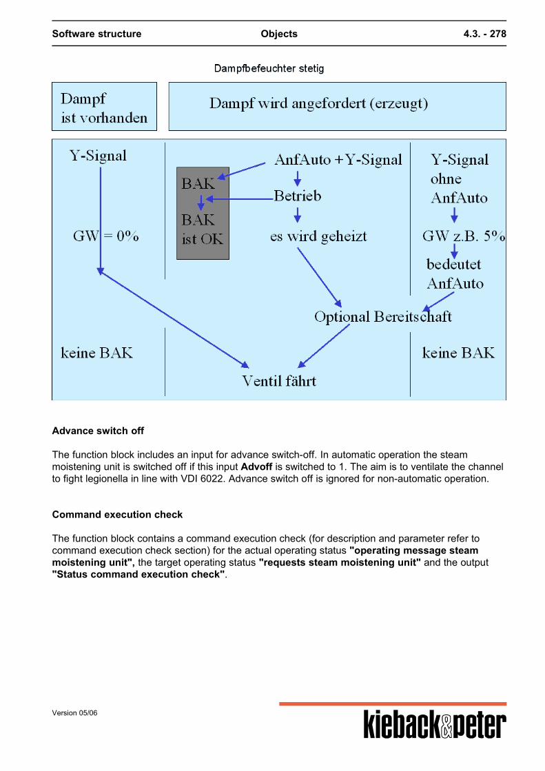
Software structure Objects 4.3. - 278
Advance switch off
The function block includes an input for advance switch-off. In automatic operation the steammoistening unit is switched off if this input Advoff is switched to 1. The aim is to ventilate the channelto fight legionella in line with VDI 6022. Advance switch off is ignored for non-automatic operation.
Command execution check
The function block contains a command execution check (for description and parameter refer tocommand execution check section) for the actual operating status "operating message steammoistening unit", the target operating status "requests steam moistening unit" and the output"Status command execution check".
Version 05/06
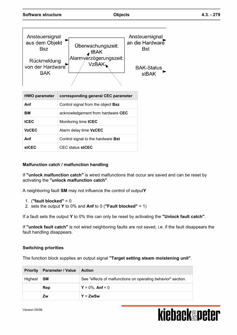
Software structure Objects 4.3. - 279
HWO parameter corresponding general CEC parameter
Anf Control signal from the object Bsz
BM acknowledgement from hardware CEC
tCEC Monitoring time tCEC
VzCEC Alarm delay time VzCEC
Anf Control signal to the hardware Bst
stCEC CEC status stCEC
Malfunction catch / malfunction handling
If "unlock malfunction catch" is wired malfunctions that occur are saved and can be reset byactivating the "unlock malfunction catch". A neighboring fault SM may not influence the control of outputY
1. ("fault blocked" = 02. sets the output Y to 0% and Anf to 0 ("Fault blocked" = 1)
If a fault sets the output Y to 0% this can only be reset by activating the "Unlock fault catch". If "unlock fault catch" is not wired neighboring faults are not saved, i.e. if the fault disappears thefault handling disappears.
Switching priorities
The function block supplies an output signal "Target setting steam moistening unit".
Priority Parameter / Value Action
Highest SM See "effects of malfunctions on operating behavior" section.
Rep Y = 0%, Anf = 0
Zw Y = ZwSw
Version 05/06

Software structure Objects 4.3. - 280
Priority Parameter / Value Action
Manual Y = Manual
DOL Y = 0%, Anf = 0
Z Y = Z
Preset = 1 Y = 0%, Anf = 0
lowest Auto Y = Ytarget
Version 05/06
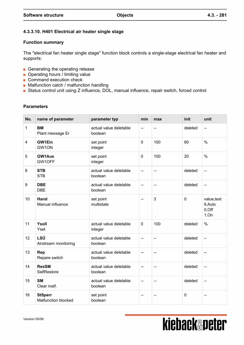
Software structure Objects 4.3. - 281
4.3.3.10. H401 Electrical air heater single stage
Function summary
The "electrical fan heater single stage" function block controls a single-stage electrical fan heater andsupports:
Generating the operating release Operating hours / limiting value Command execution check Malfunction catch / malfunction handling Status control unit using Z influence, DOL, manual influence, repair switch, forced control
Parameters
No. name of parameter parameter typ min max init unit
1 BMPlant message Er
actual value deletableboolean
-- -- deleted --
4 GW1EinGW1ON
set pointinteger
0 100 60 %
5 GW1AusGW1OFF
set pointinteger
0 100 20 %
8 STBSTB
actual value deletableboolean
-- -- deleted --
9 DBEDBE
actual value deletableboolean
-- -- deleted --
10 HandManual influence
set pointmultistate
-- 3 0 value,text9,Auto0,Off1,On
11 YsollYset
actual value deletableinteger
0 100 deleted %
12 LSÜAirstream monitoring
actual value deletableboolean
-- -- deleted --
13 RepRepare switch
actual value deletableboolean
-- -- deleted --
14 ResSMSelfRestore
actual value deletableboolean
-- -- deleted --
15 SMClear malf.
actual value deletableboolean
-- -- deleted --
16 StSperrMalfunction blocked
set pointboolean
-- -- 0 --
Version 05/06
Software structure Objects 4.3. - 282
No. name of parameter parameter typ min max init unit
17 VzBAKstBAK delayed
set pointinteger
0 2147483647 0 s
18 ZZ- influence
set pointmultistate
-- 3 0 value,text9,Auto0,Off1,On
19 ZwForced control
set pointmultistate
-- 3 0 value,text9,Auto0,Off1,On
20 gBhLimit value infringement
actual valueboolean
-- -- 0 --
21 Erh1Anfo heater 1
actual valueboolean
-- -- 0 --
25 stBAKMalf. BAK
actual valueboolean
-- -- 0 --
30 tBAKDelay BAK
set pointinteger
0 2147483647 30 s
31 BhOperating hours
set pointinteger
0 2147483647 0 h
32 BhAktivActive opr. hours
set pointboolean
-- -- 0 --
33 BhGwTotal opr.hours
set pointinteger
0 2147483647 0 h
34 ResBhReset opr. hours
actual value deletableboolean
-- -- deleted --
35 SMoutSMout
actual valueboolean
-- -- 0 --
Function description
Generating the operating release
A request in automatic operation is recognized by the Ytarget as being above a limitingvalue GWOn (Basis: 60%). It is ended when the value is lower than the limiting valueGWOff (Basis: 20 %). In addition for a request the "air flow monitoring" (even in Z-,forced or manual operation) must provide a normal message.
The " safety temperature limiter" also ends the request chain in non-automaticoperation.
Version 05/06
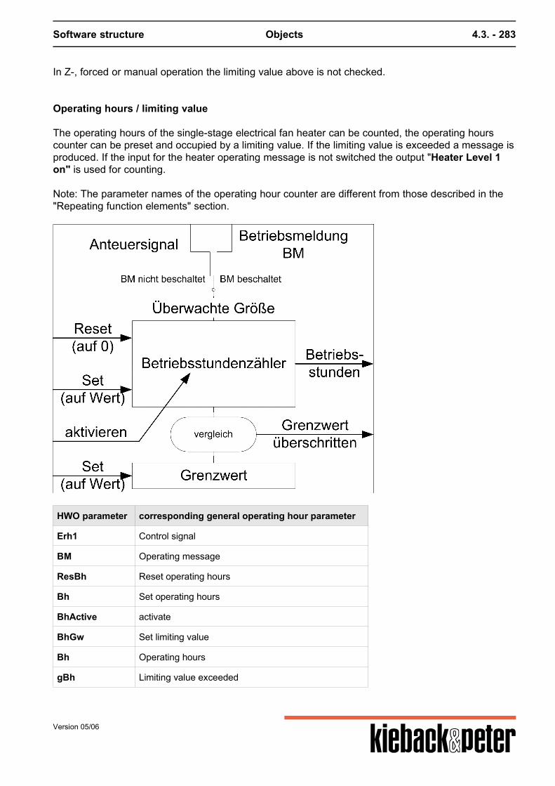
Software structure Objects 4.3. - 283
In Z-, forced or manual operation the limiting value above is not checked.
Operating hours / limiting value
The operating hours of the single-stage electrical fan heater can be counted, the operating hourscounter can be preset and occupied by a limiting value. If the limiting value is exceeded a message isproduced. If the input for the heater operating message is not switched the output "Heater Level 1on" is used for counting. Note: The parameter names of the operating hour counter are different from those described in the"Repeating function elements" section.
HWO parameter corresponding general operating hour parameter
Erh1 Control signal
BM Operating message
ResBh Reset operating hours
Bh Set operating hours
BhActive activate
BhGw Set limiting value
Bh Operating hours
gBh Limiting value exceeded
Version 05/06
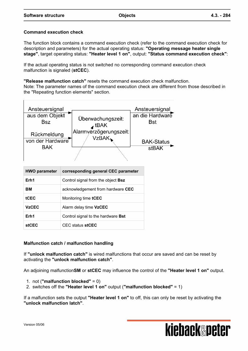
Software structure Objects 4.3. - 284
Command execution check
The function block contains a command execution check (refer to the command execution check fordescription and parameters) for the actual operating status: "Operating message heater singlestage", target operating status: "Heater level 1 on", output: "Status command execution check": If the actual operating status is not switched no corresponding command execution checkmalfunction is signaled (stCEC). "Release malfunction catch" resets the command execution check malfunction.Note: The parameter names of the command execution check are different from those described inthe "Repeating function elements" section.
HWO parameter corresponding general CEC parameter
Erh1 Control signal from the object Bsz
BM acknowledgement from hardware CEC
tCEC Monitoring time tCEC
VzCEC Alarm delay time VzCEC
Erh1 Control signal to the hardware Bst
stCEC CEC status stCEC
Malfunction catch / malfunction handling
If "unlock malfunction catch" is wired malfunctions that occur are saved and can be reset byactivating the "unlock malfunction catch". An adjoining malfunctionSM or stCEC may influence the control of the "Heater level 1 on" output.
1. not ("malfunction blocked" = 0)2. switches off the "Heater level 1 on" output ("malfunction blocked" = 1)
If a malfunction sets the output "Heater level 1 on" to off, this can only be reset by activating the"unlock malfunction latch".
Version 05/06
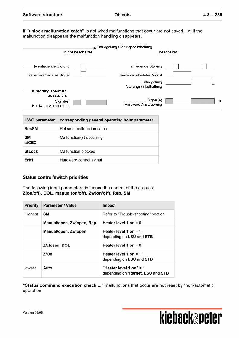
Software structure Objects 4.3. - 285
If "unlock malfunction catch" is not wired malfunctions that occur are not saved, i.e. if themalfunction disappears the malfunction handling disappears.
HWO parameter corresponding general operating hour parameter
ResSM Release malfunction catch
SMstCEC
Malfunction(s) occurring
StLock Malfunction blocked
Erh1 Hardware control signal
Status control/switch priorities
The following input parameters influence the control of the outputs:Z(on/off), DOL, manual(on/off), Zw(on/off), Rep, SM
Priority Parameter / Value Impact
Highest SM Refer to "Trouble-shooting" section
Manual/open, Zw/open, Rep Heater level 1 on = 0
Manual/open, Zw/open Heater level 1 on = 1depending on LSÜ and STB
Z/closed, DOL Heater level 1 on = 0
Z/On Heater level 1 on = 1depending on LSÜ and STB
lowest Auto "Heater level 1 on" = 1depending on Ytarget, LSÜ and STB
"Status command execution check ..." malfunctions that occur are not reset by "non-automatic"operation.
Version 05/06
Software structure Objects 4.3. - 286
4.3.3.11. H402 Electrical air heater 2 stage
Function summary
The "electrical fan heater two stage" function block controls a two-stage electrical fan heater andsupports:
Generating the operating release Operating hours / limiting value Command execution check Malfunction catch / malfunction handling Status control unit using Z influence, DOL, manual influence, repair switch, forced control
Parameters
No. name of parameter parameter typ min max init unit
1 BM1Plant message St1
actual value deletableboolean
-- -- deleted --
2 BM2Plant message St2
actual value deletableboolean
-- -- deleted --
4 GW1EinGW1ON
set pointinteger
0 100 40 %
5 GW1AusGW1OFF
set pointinteger
0 100 20 %
6 GW2EinGW2ON
set pointinteger
0 100 70 %
7 GW2AusGW2OFF
set pointinteger
0 100 55 %
8 STBSTB
actual value deletableboolean
-- -- deleted --
9 DBEDBE
actual value deletableboolean
-- -- deleted --
10 HandManual influence
set pointmultistate
-- 4 0 value,text9,Auto0,Off1,Level 12,Level 2
11 YsollYset
actual value deletableinteger
0 100 deleted %
12 LSÜAir stream monitoring
actual value deletableboolean
-- -- deleted --
13 RepRep.switch
actual value deletableboolean
-- -- deleted --
Version 05/06
Software structure Objects 4.3. - 287
No. name of parameter parameter typ min max init unit
14 ResSMSelfRestore
actual value deletableboolean
-- -- deleted --
15 SMClear malf.
actual value deletableboolean
-- -- deleted --
16 StSperrMalfunction blocked
set pointboolean
-- -- 0 --
17 VzBAKstBAK delayed
set pointinteger
0 2147483647 0 s
18 ZZ- influence
set pointmultistate
-- 4 0 value,text9,Z-Auto0,Z-OFF1,Z-Level 12,Z-Level 2
19 ZwForced control
set pointmultistate
-- 4 0 value,text9,Auto0,Off1,Level 12,Level 2
20 gBhGW-Verl. Bh
actual valueboolean
-- -- 0 --
21 Erh1Anfo heater 1
actual valueboolean
-- -- 0 --
22 Erh2Anfo heater 2
actual valueboolean
-- -- 0 --
25 stBAK1Malf. BAK 1
actual valueboolean
-- -- 0 --
26 stBAK2Malf. BAK2
actual valueboolean
-- -- 0 --
30 tBAKDelay BAK
set pointinteger
0 2147483647 30 s
31 BhOperating hours
set pointinteger
0 2147483647 0 h
32 BhAktivActive opr. hours
set pointboolean
-- -- 0 --
33 BhGwTotal opr.hours
set pointinteger
0 2147483647 0 h
34 ResBhReset opr. hours
actual value deletableboolean
-- -- deleted --
Version 05/06
Software structure Objects 4.3. - 288
No. name of parameter parameter typ min max init unit
35 SMoutSMout
actual valueboolean
-- -- 0 --
Generating the operating release
A Level 1 release is recognized by the Ytarget as being above a limiting value GW1On(Basis: 40 %). It is ended when the value is lower than the limiting value GW1Off (Basis:20 %). For the level 2 requests the GW2On (Basis: 20 %) and GW2Off (Basis: 55 %)limiting values apply. In addition for a request the "air flow monitoring" (even in Z-,
forced or manual operation) must provide a normal message.
The outputs "Heater level 1 on" and "Heater Level 2 on" outputs are not locked against each other.
The " safety temperature limiter" also ends the request chain in non-automaticoperation.
In Z-, forced or manual operation the limiting value above is not checked.
Operating hours / limiting value
The operating hours of the two-stage electrical fan heater can be counted, the operating hourscounter can be preset and occupied by a limiting value. If the limiting value is exceeded a message isproduced. If the corresponding input for the heater operating message is not switched the output"Heater Level 1 on" or "Heater level 2"is used for counting. Note: The parameter names of the operating hour counter are different from those described in the"Repeating function elements" section.
Version 05/06
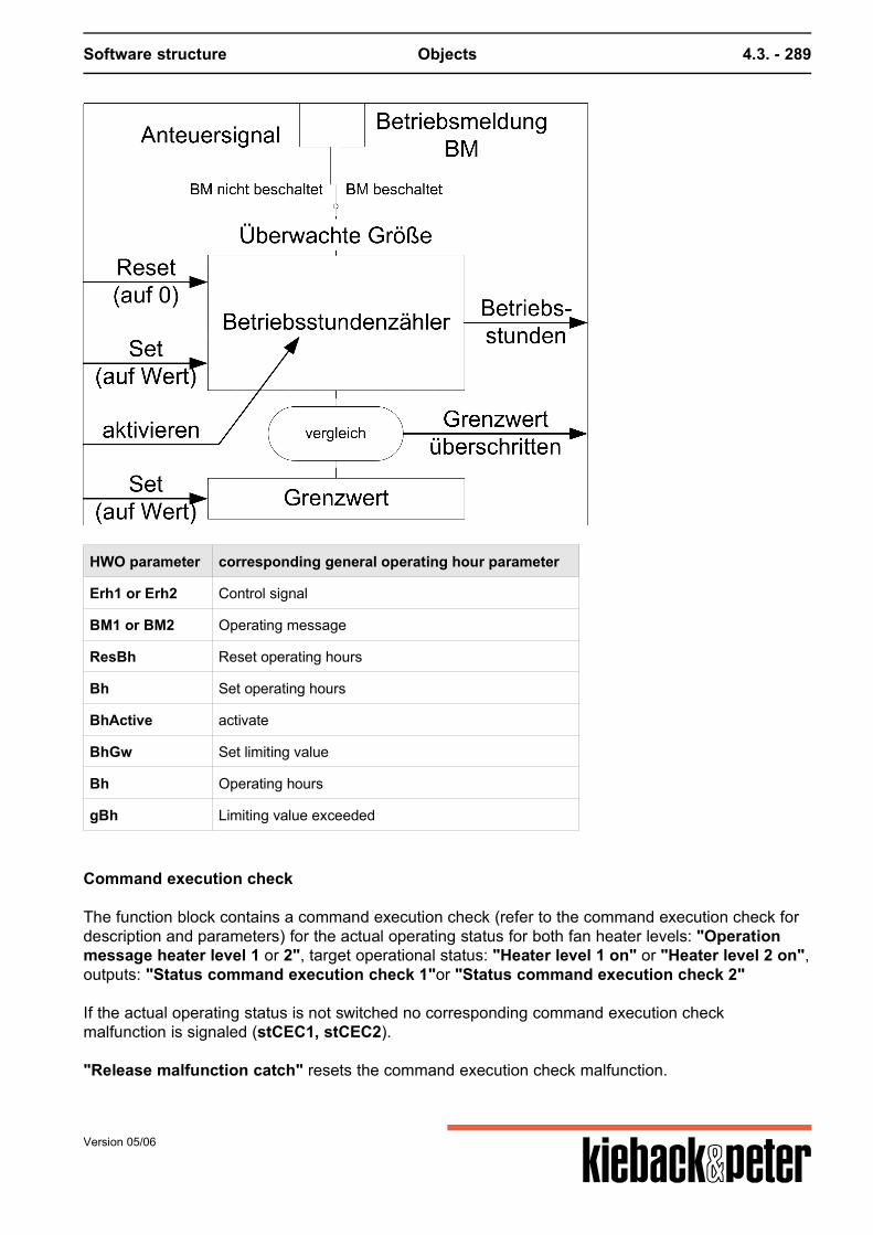
Software structure Objects 4.3. - 289
HWO parameter corresponding general operating hour parameter
Erh1 or Erh2 Control signal
BM1 or BM2 Operating message
ResBh Reset operating hours
Bh Set operating hours
BhActive activate
BhGw Set limiting value
Bh Operating hours
gBh Limiting value exceeded
Command execution check
The function block contains a command execution check (refer to the command execution check fordescription and parameters) for the actual operating status for both fan heater levels: "Operationmessage heater level 1 or 2", target operational status: "Heater level 1 on" or "Heater level 2 on",outputs: "Status command execution check 1"or "Status command execution check 2" If the actual operating status is not switched no corresponding command execution checkmalfunction is signaled (stCEC1, stCEC2). "Release malfunction catch" resets the command execution check malfunction.
Version 05/06
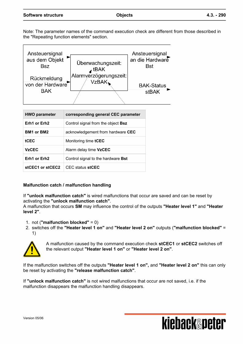
Software structure Objects 4.3. - 290
Note: The parameter names of the command execution check are different from those described inthe "Repeating function elements" section.
HWO parameter corresponding general CEC parameter
Erh1 or Erh2 Control signal from the object Bsz
BM1 or BM2 acknowledgement from hardware CEC
tCEC Monitoring time tCEC
VzCEC Alarm delay time VzCEC
Erh1 or Erh2 Control signal to the hardware Bst
stCEC1 or stCEC2 CEC status stCEC
Malfunction catch / malfunction handling
If "unlock malfunction catch" is wired malfunctions that occur are saved and can be reset byactivating the "unlock malfunction catch".A malfunction that occurs SM may influence the control of the outputs "Heater level 1" and "Heaterlevel 2".
1. not ("malfunction blocked" = 0)2. switches off the "Heater level 1 on" and "Heater level 2 on" outputs ("malfunction blocked" =
1)
A malfunction caused by the command execution check stCEC1 or stCEC2 switches offthe relevant output "Heater level 1 on" or "Heater level 2 on".
If the malfunction switches off the outputs "Heater level 1 on", and "Heater level 2 on" this can onlybe reset by activating the "release malfunction catch". If "unlock malfunction catch" is not wired malfunctions that occur are not saved, i.e. if themalfunction disappears the malfunction handling disappears.
Version 05/06
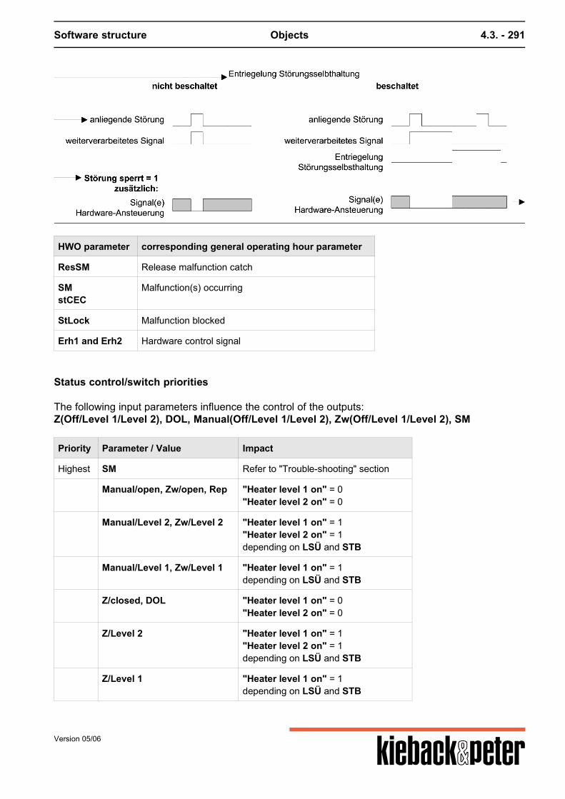
Software structure Objects 4.3. - 291
HWO parameter corresponding general operating hour parameter
ResSM Release malfunction catch
SMstCEC
Malfunction(s) occurring
StLock Malfunction blocked
Erh1 and Erh2 Hardware control signal
Status control/switch priorities
The following input parameters influence the control of the outputs:Z(Off/Level 1/Level 2), DOL, Manual(Off/Level 1/Level 2), Zw(Off/Level 1/Level 2), SM
Priority Parameter / Value Impact
Highest SM Refer to "Trouble-shooting" section
Manual/open, Zw/open, Rep "Heater level 1 on" = 0"Heater level 2 on" = 0
Manual/Level 2, Zw/Level 2 "Heater level 1 on" = 1"Heater level 2 on" = 1depending on LSÜ and STB
Manual/Level 1, Zw/Level 1 "Heater level 1 on" = 1depending on LSÜ and STB
Z/closed, DOL "Heater level 1 on" = 0"Heater level 2 on" = 0
Z/Level 2 "Heater level 1 on" = 1"Heater level 2 on" = 1depending on LSÜ and STB
Z/Level 1 "Heater level 1 on" = 1depending on LSÜ and STB
Version 05/06

Software structure Objects 4.3. - 292
Priority Parameter / Value Impact
lowest Auto "Heater level 1 on" = 1 and/or"Heater level 2 on"depending on Ytarget, LSÜ and STB
"Status command execution check ..." malfunctions that occur are not reset by "non-automatic"operation.
Version 05/06
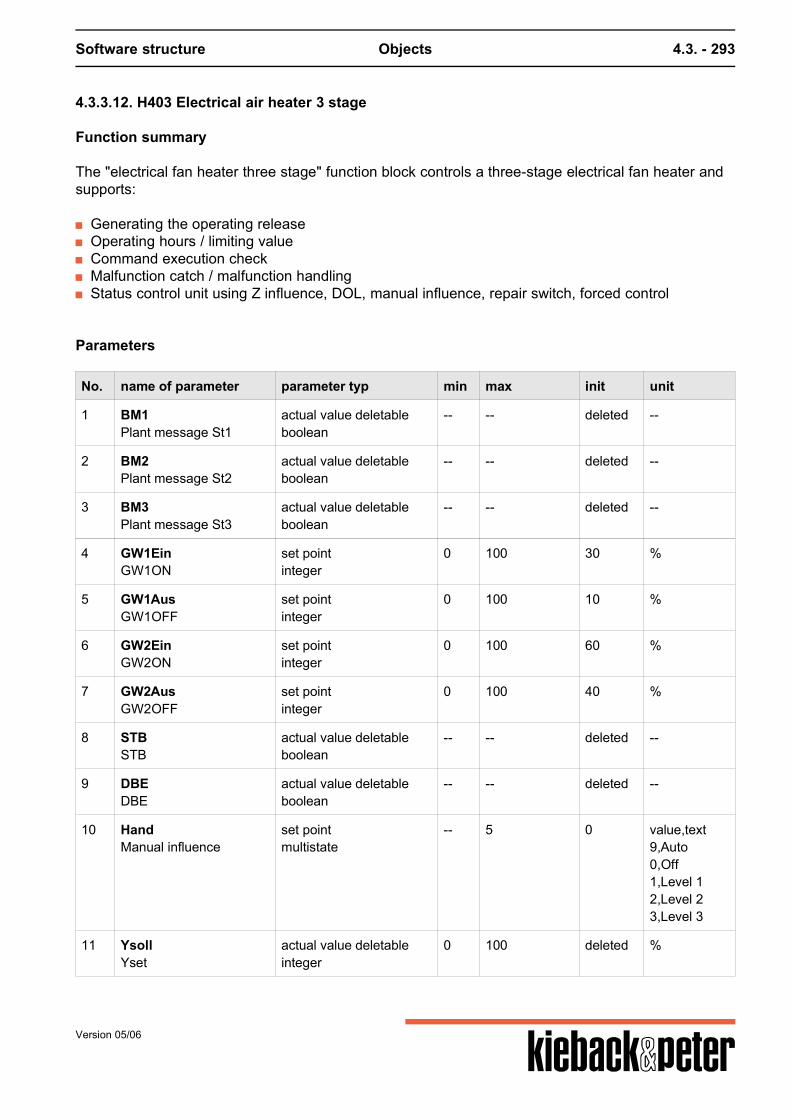
Software structure Objects 4.3. - 293
4.3.3.12. H403 Electrical air heater 3 stage
Function summary
The "electrical fan heater three stage" function block controls a three-stage electrical fan heater andsupports:
Generating the operating release Operating hours / limiting value Command execution check Malfunction catch / malfunction handling Status control unit using Z influence, DOL, manual influence, repair switch, forced control
Parameters
No. name of parameter parameter typ min max init unit
1 BM1Plant message St1
actual value deletableboolean
-- -- deleted --
2 BM2Plant message St2
actual value deletableboolean
-- -- deleted --
3 BM3Plant message St3
actual value deletableboolean
-- -- deleted --
4 GW1EinGW1ON
set pointinteger
0 100 30 %
5 GW1AusGW1OFF
set pointinteger
0 100 10 %
6 GW2EinGW2ON
set pointinteger
0 100 60 %
7 GW2AusGW2OFF
set pointinteger
0 100 40 %
8 STBSTB
actual value deletableboolean
-- -- deleted --
9 DBEDBE
actual value deletableboolean
-- -- deleted --
10 HandManual influence
set pointmultistate
-- 5 0 value,text9,Auto0,Off1,Level 12,Level 23,Level 3
11 YsollYset
actual value deletableinteger
0 100 deleted %
Version 05/06
Software structure Objects 4.3. - 294
No. name of parameter parameter typ min max init unit
12 LSÜAir stream monitoring
actual value deletableboolean
-- -- deleted --
13 RepRep.switch
actual value deletableboolean
-- -- deleted --
14 ResSMSelfRestore
actual value deletableboolean
-- -- deleted --
15 SMClear malf.
actual value deletableboolean
-- -- deleted --
16 StSperrMalfunction blocked
set pointboolean
-- -- 0 --
17 VzBAKstBAK delayed
set pointinteger
0 2147483647 0 s
18 ZZ- influence
set pointmultistate
-- 5 0 value,text9,Z-Auto0,Z-OFF1,Z-Level 12,Z-Level 23,Z-Level 3
19 ZwForced control
set pointmultistate
-- 5 0 value,text9,Auto0,Off1,Level 12,Level 23,Level 3
20 gBhLV-viol. Bh
actual valueboolean
-- -- 0 --
21 Erh1Anfo heater 1
actual valueboolean
-- -- 0 --
22 Erh2Anfo heater 2
actual valueboolean
-- -- 0 --
23 Erh3Anfo heater 3
actual valueboolean
-- -- 0 --
25 stBAK1Malf. BAK 1
actual valueboolean
-- -- 0 --
26 stBAK2Malf. BAK2
actual valueboolean
-- -- 0 --
27 stBAK3Malf. BAK3
actual valueboolean
-- -- 0 --
30 tBAKDelay BAK
set pointinteger
0 2147483647 30 s
Version 05/06
Software structure Objects 4.3. - 295
No. name of parameter parameter typ min max init unit
31 BhOperating hours
set pointinteger
0 2147483647 0 h
32 BhAktivActive opr. hours
set pointboolean
-- -- 0 --
33 BhGwTotal opr.hours
set pointinteger
0 2147483647 0 h
34 ResBhReset opr. hours
actual value deletableboolean
-- -- deleted --
35 GW3EinGW3ON
set pointinteger
0 100 90 %
36 GW3AusGW3OFF
set pointinteger
0 100 70 %
37 SMoutSMout
actual valueboolean
-- -- 0 --
Function description
Generating the operating release
A Level 1 release is recognized by the Ytarget being above a limiting value GW1On(Basis: 30 %). It is ended when the value is lower than the limiting value GW1Off (Basis:10 %). For the release of level 2 the GW2On (Basis: 60 %) and GW2Off (Basis: 40 %)limiting values apply. For the release of level 3 the GW3On (Basis: 90 %) and GW3Off
(Basis: 70 %) limiting values apply. In addition for a request the "air flow monitoring" (even in Z-,forced or manual operation) must provide a normal message.
The outputs "Heater level 1 on" and "Heater Level 2 on" and"Heater level 3 on" are not lockedagainst each other.
The " safety temperature limiter" also ends the request chain in non-automaticoperation.
In Z-, forced or manual operation the limiting value above is not checked.
Operating hours / limiting value
The operating hours of the three-stage electrical fan heater can be counted, the operating hourscounter can be preset and occupied by a limiting value. If the limiting value is exceeded a message isproduced. If the corresponding input for the electrical heater operating message is not switched theoutput "Heater Level 1 on", "Heater level 2" or "Heater level 3"is used for counting.Note: The parameter names of the operating hour counter are different from those described in the"Repeating function elements" section.
Version 05/06
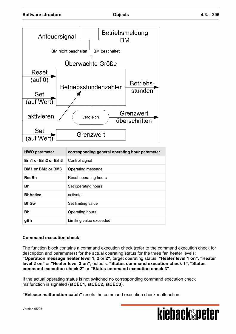
Software structure Objects 4.3. - 296
HWO parameter corresponding general operating hour parameter
Erh1 or Erh2 or Erh3 Control signal
BM1 or BM2 or BM3 Operating message
ResBh Reset operating hours
Bh Set operating hours
BhActive activate
BhGw Set limiting value
Bh Operating hours
gBh Limiting value exceeded
Command execution check
The function block contains a command execution check (refer to the command execution check fordescription and parameters) for the actual operating status for the three fan heater levels:"Operation message heater level 1, 2 or 2", target operating status: "Heater level 1 on", "Heaterlevel 2 on" or "Heater level 3 on", outputs: "Status command execution check 1", "Statuscommand execution check 2" or "Status command execution check 3". If the actual operating status is not switched no corresponding command execution checkmalfunction is signaled (stCEC1, stCEC2, stCEC3). "Release malfunction catch" resets the command execution check malfunction.
Version 05/06
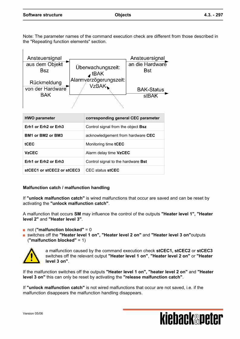
Software structure Objects 4.3. - 297
Note: The parameter names of the command execution check are different from those described inthe "Repeating function elements" section.
HWO parameter corresponding general CEC parameter
Erh1 or Erh2 or Erh3 Control signal from the object Bsz
BM1 or BM2 or BM3 acknowledgement from hardware CEC
tCEC Monitoring time tCEC
VzCEC Alarm delay time VzCEC
Erh1 or Erh2 or Erh3 Control signal to the hardware Bst
stCEC1 or stCEC2 or stCEC3 CEC status stCEC
Malfunction catch / malfunction handling
If "unlock malfunction catch" is wired malfunctions that occur are saved and can be reset byactivating the "unlock malfunction catch". A malfunction that occurs SM may influence the control of the outputs "Heater level 1", "Heaterlevel 2" and "Heater level 3".
not ("malfunction blocked" = 0 switches off the "Heater level 1 on", "Heater level 2 on" and "Heater level 3 on"outputs
("malfunction blocked" = 1)
a malfunction caused by the command execution check stCEC1, stCEC2 or stCEC3switches off the relevant output "Heater level 1 on", "Heater level 2 on" or "Heaterlevel 3 on".
If the malfunction switches off the outputs "Heater level 1 on", "heater level 2 on" and "Heaterlevel 3 on" this can only be reset by activating the "release malfunction catch". If "unlock malfunction catch" is not wired malfunctions that occur are not saved, i.e. if themalfunction disappears the malfunction handling disappears.
Version 05/06
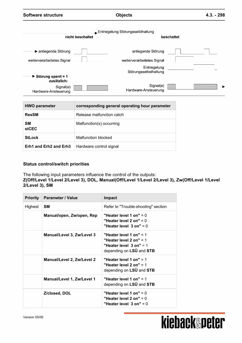
Software structure Objects 4.3. - 298
HWO parameter corresponding general operating hour parameter
ResSM Release malfunction catch
SMstCEC
Malfunction(s) occurring
StLock Malfunction blocked
Erh1 and Erh2 and Erh3 Hardware control signal
Status control/switch priorities
The following input parameters influence the control of the outputs:Z(Off/Level 1/Level 2/Level 3), DOL, Manual(Off/Level 1/Level 2/Level 3), Zw(Off/Level 1/Level2/Level 3), SM
Priority Parameter / Value Impact
Highest SM Refer to "Trouble-shooting" section
Manual/open, Zw/open, Rep "Heater level 1 on" = 0"Heater level 2 on" = 0"Heater level 3 on" = 0
Manual/Level 3, Zw/Level 3 "Heater level 1 on" = 1"Heater level 2 on" = 1"Heater level 3 on" = 1depending on LSÜ and STB
Manual/Level 2, Zw/Level 2 "Heater level 1 on" = 1"Heater level 2 on" = 1depending on LSÜ and STB
Manual/Level 1, Zw/Level 1 "Heater level 1 on" = 1depending on LSÜ and STB
Z/closed, DOL "Heater level 1 on" = 0"Heater level 2 on" = 0"Heater level 3 on" = 0
Version 05/06
Software structure Objects 4.3. - 299
Priority Parameter / Value Impact
Z/Level 3 "Heater level 1 on" = 1"Heater level 2 on" = 1"Heater level 3 on" = 1depending on LSÜ and STB
Z/Level 2 "Heater level 1 on" = 1"Heater level 2 on" = 1depending on LSÜ and STB
Z/Level 1 "Heater level 1 on" = 1depending on LSÜ and STB
lowest Auto "Heater level 1 on" = 1 and/or"Heater level 2 on" = 1 and/or"Heater level 3 on" = 1depending on Ytarget, LSÜ and STB
"Status command execution check ..." malfunctions that occur are not reset by "non-automatic"operation.
Version 05/06
Software structure Objects 4.3. - 300
4.3.3.13. H404 Electrical air heater constant
Function summary
The "electrical fan heater constant" function block controls a constant electrical fan heater andsupports:
Generating the operating release Command execution check Malfunction catch / malfunction handling Status control unit using Z influence, DOL, manual influence, repair switch, forced control
Parameters
No. name of parameter parameter typ min max init unit
1 BMAbout message
actual value deletableboolean
-- -- deleted --
4 GWYsollGWYset
set pointinteger
0 100 5 %
6 YSetp. heater
actual valueinteger
0 100 1 %
8 STBSTB
actual value deletableboolean
-- -- deleted --
9 DBEDBE
actual value deletableboolean
-- -- deleted --
10 HandManual influence
set point deletableinteger
0 100 deleted %
11 YsollYset
actual value deletableinteger
0 100 deleted %
12 LSÜAir stream monitoring
actual value deletableboolean
-- -- deleted --
13 RepRepair switch
actual value deletableboolean
-- -- deleted --
14 ResSMSelfRestore
actual value deletableboolean
-- -- deleted --
15 SMClear malf.
actual value deletableboolean
-- -- deleted --
16 StSperrMalfunction blocks
set pointboolean
-- -- 0 --
17 VzBAKstBAK delayed
set pointinteger
0 2147483647 0 s
Version 05/06
Software structure Objects 4.3. - 301
No. name of parameter parameter typ min max init unit
18 ZZ- influence
set point deletableinteger
0 100 deleted %
19 ZwForced control
set point deletableinteger
0 100 deleted %
21 AnfAnfo recv contin.
actual valueboolean
-- -- 0 --
25 stBAKMalf. BAK
actual valueboolean
-- -- 0 --
30 tBAKDelay BAK
set pointinteger
0 2147483647 30 s
31 SMoutSMout
actual valueboolean
-- -- 0 --
Function description
Generating the operating release
A request in automatic operation is recognized by the Ytarget being above a limiting valueGWYtarget (Basis: 5%). The limiting value view is marked with a fixed hysteresis (Xsd) of3%. In addition for a request the "air flow monitoring" (even in Z-, forced or manualoperation) must provide a normal message.
The " safety temperature limiter" also ends the request chain in non-automaticoperation.
In Z-, forced or manual operation the limiting value above is not checked.The target operating status "request electrical fan heater constant" is formed from the view aboveand from , Z, DOL, manual, Zw and ZwSw, Rep, SM, see below for priorities.
Command execution check
The function block contains a command execution check (refer to the command execution check fordescription and parameters) for the actual operating status: "Operating message electrical fanheater", Target operating status: "request electrical fan heater constant", output: "StatusCommand execution check" If the actual operating status is not switched no corresponding command execution checkmalfunction is signaled (stCEC). "Release malfunction catch" resets the command execution check malfunction. Note: The parameter names of the command execution check are different from those described inthe "Repeating function elements" section.
Version 05/06
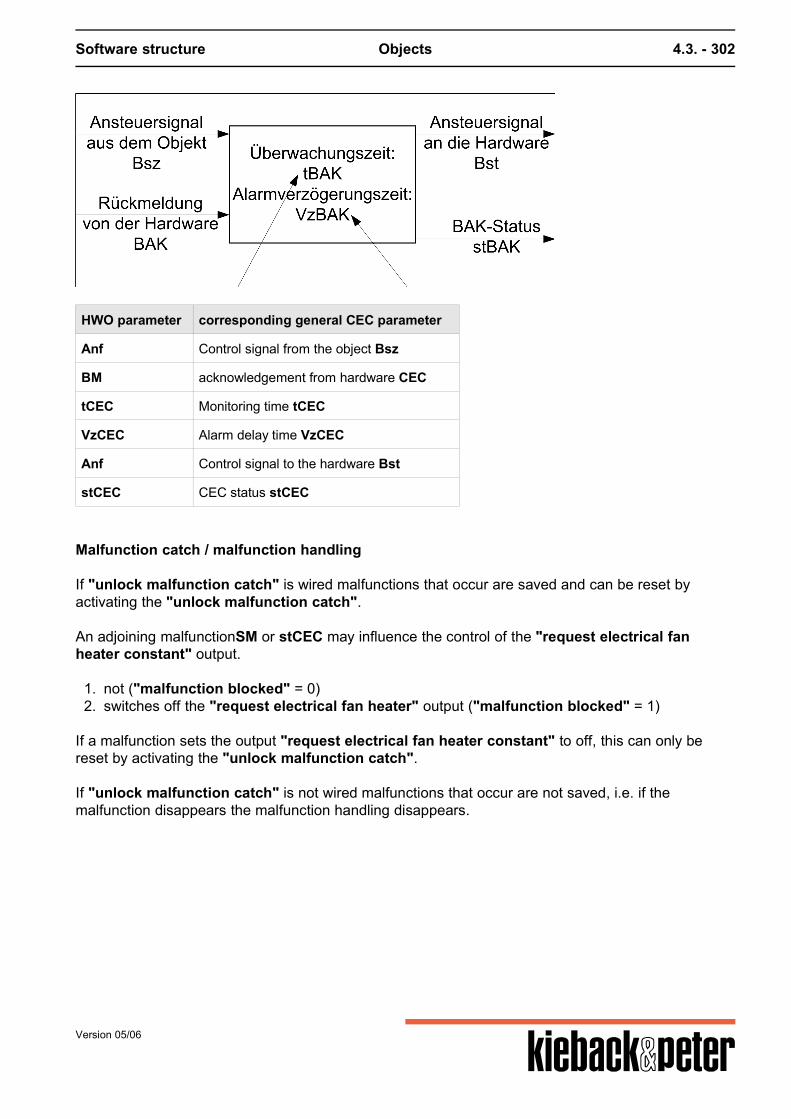
Software structure Objects 4.3. - 302
HWO parameter corresponding general CEC parameter
Anf Control signal from the object Bsz
BM acknowledgement from hardware CEC
tCEC Monitoring time tCEC
VzCEC Alarm delay time VzCEC
Anf Control signal to the hardware Bst
stCEC CEC status stCEC
Malfunction catch / malfunction handling
If "unlock malfunction catch" is wired malfunctions that occur are saved and can be reset byactivating the "unlock malfunction catch". An adjoining malfunctionSM or stCEC may influence the control of the "request electrical fanheater constant" output.
1. not ("malfunction blocked" = 0)2. switches off the "request electrical fan heater" output ("malfunction blocked" = 1)
If a malfunction sets the output "request electrical fan heater constant" to off, this can only bereset by activating the "unlock malfunction catch". If "unlock malfunction catch" is not wired malfunctions that occur are not saved, i.e. if themalfunction disappears the malfunction handling disappears.
Version 05/06
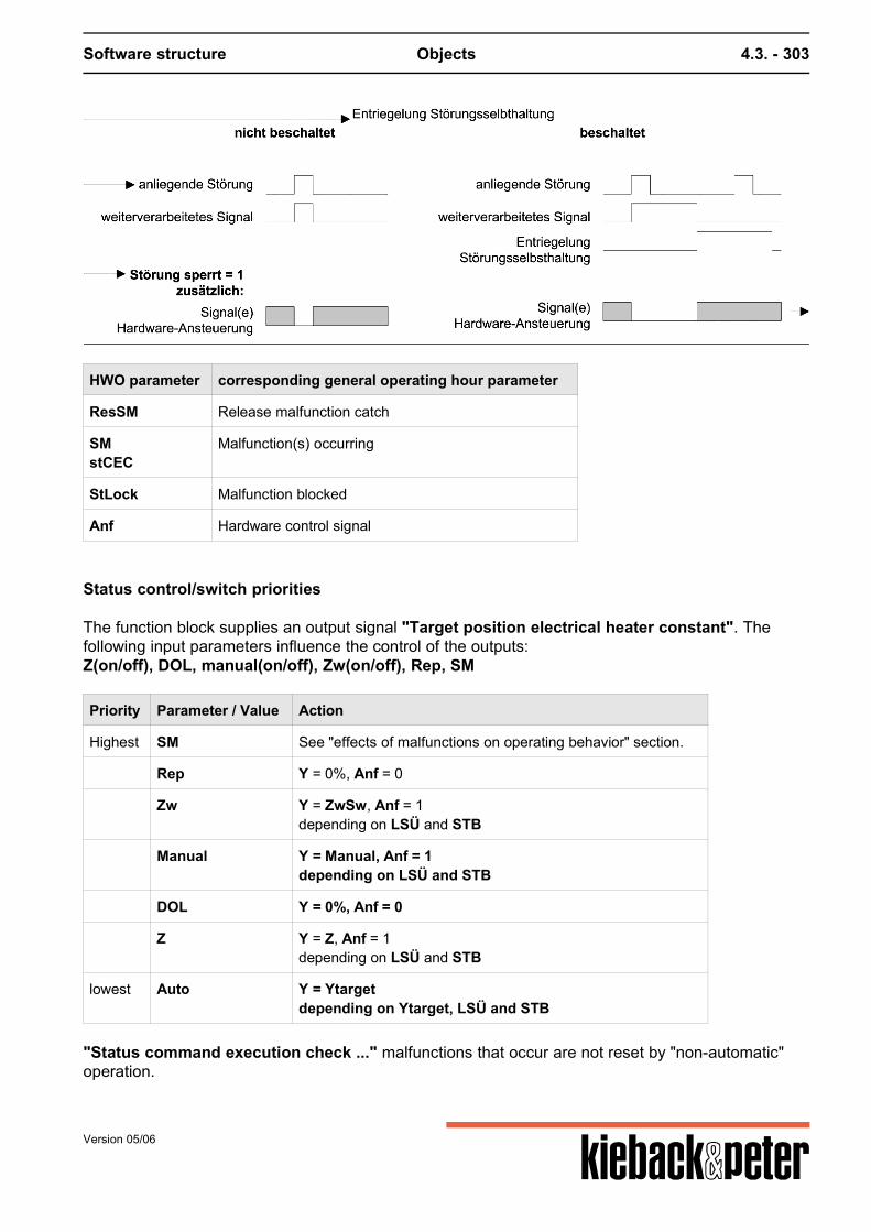
Software structure Objects 4.3. - 303
HWO parameter corresponding general operating hour parameter
ResSM Release malfunction catch
SMstCEC
Malfunction(s) occurring
StLock Malfunction blocked
Anf Hardware control signal
Status control/switch priorities
The function block supplies an output signal "Target position electrical heater constant". Thefollowing input parameters influence the control of the outputs:Z(on/off), DOL, manual(on/off), Zw(on/off), Rep, SM
Priority Parameter / Value Action
Highest SM See "effects of malfunctions on operating behavior" section.
Rep Y = 0%, Anf = 0
Zw Y = ZwSw, Anf = 1depending on LSÜ and STB
Manual Y = Manual, Anf = 1depending on LSÜ and STB
DOL Y = 0%, Anf = 0
Z Y = Z, Anf = 1depending on LSÜ and STB
lowest Auto Y = Ytargetdepending on Ytarget, LSÜ and STB
"Status command execution check ..." malfunctions that occur are not reset by "non-automatic"operation.
Version 05/06

Software structure Objects 4.3. - 304
Version 05/06
Software structure Objects 4.3. - 305
4.3.3.14. H501 Cover open/closed
Function summary
The "cover open/closed" function block controls a cover that can be opened or closed and considersa cover run time.
The function block supports:
Final position replication Command execution check Trouble-shooting Status control unit using Z influence, DOL, manual influence, forced control
The RPG function block is basically identical to "Valve open/closed", the blocking protection is notrequired and some parameter names in the DDC4000 object are different.
Parameters
No. name of parameter parameter typ min max init unit
1 AnfAutoBegin Automatic
actual value deletableboolean
-- -- deleted --
2 AufEnd pos. OPEN
actual value deletableboolean
-- -- deleted --
3 DBEDirect operating level active
actual value deletableboolean
-- -- deleted --
4 HandManual influence
set pointmultistate
-- 3 0 value,text9,Manual Auto1,Manual OPEN0,Manual SHUT
5 ResSMEntr. Malfunction catch
actual value deletableboolean
-- -- deleted --
6 StSperrMalfunction blocked
set pointboolean
-- -- 0 --
7 StellSetting
actual valuemultistate
-- 3 1 value,text1,OPEN0,SHUT24,Running
8 VzBAKStBAK delayed
set pointinteger
0 2147483647 0 s
9 YFlap drive
actual valueboolean
-- -- 0 --
10 YrSet.feedb. flap
actual value deletableinteger
0 100 deleted %
Version 05/06
Software structure Objects 4.3. - 306
No. name of parameter parameter typ min max init unit
11 ZZ- influence
set pointmultistate
-- 3 0 value,text9,Z-Auto1,Z OPEN0,Z SHUT
12 ZuEnd pos. SHUT
actual value deletableboolean
-- -- deleted --
13 ZwForced control
set pointmultistate
-- 3 0 value,text9,Forced Auto1,Forced OPEN0,Forced SHUT
14 stBAKStatus BAK
actual valueboolean
-- -- 0 --
15 tBAKTime BAK
set pointinteger
0 2147483647 30 s
16 tMotMotor runtime
set pointinteger
0 600 120 s
Function description
Final position replication
The "final position open", "final position closed" and "position feedback signal cover" inputscan be wired if required.If the "position feedback signal cover" is wired, but not the"final position open" and "finalposition closed", both final positions are determined via the "position feedback signal cover". If"position feedback signal cover" < 3 % a "closed" final position is assumed, if "position feedbacksignal cover" > 97 % an "open" final position is assumed, otherwise "running".If the plant in addition to "position feedback signal cover"is also wired for "final position open" or"final position open" these inputs have higher priority.If only one of the "final position open" or "final position closed" is switched but not "positionfeedback signal cover", the final position that is not switched is determined via the "motoroperating time".If e.g. only "final position closed" is switched after an "open" control the "Setting" output is first setto "running" and after the end of the "Motor operating time" set to "open".If both "final position open" and "final position closed" are not switched the final positionreplication occurs in the same way for both final positions but a command execution check is nothowever effective.
Command execution check
The function block contains a command execution check (refer to the command execution checksection for description and parameters) for the actual operating status "Setting" that is formed asdescribed above.The target operating status is "control cover"; the output is "Status command execution check".
Version 05/06
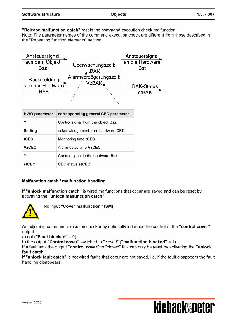
Software structure Objects 4.3. - 307
"Release malfunction catch" resets the command execution check malfunction.Note: The parameter names of the command execution check are different from those described inthe "Repeating function elements" section.
HWO parameter corresponding general CEC parameter
Y Control signal from the object Bsz
Setting acknowledgement from hardware CEC
tCEC Monitoring time tCEC
VzCEC Alarm delay time VzCEC
Y Control signal to the hardware Bst
stCEC CEC status stCEC
Malfunction catch / malfunction handling
If "unlock malfunction catch" is wired malfunctions that occur are saved and can be reset byactivating the "unlock malfunction catch".
No input "Cover malfunction" (SM).
An adjoining command execution check may optionally influence the control of the "control cover"outputa) not ("Fault blocked" = 0)b) the output "Control cover" switched to "closed" ("malfunction blocked" = 1)If a fault sets the output "control cover" to "closed" this can only be reset by activating the "unlockfault catch".If "unlock fault catch" is not wired faults that occur are not saved, i.e. if the fault disappears the faulthandling disappears.
Version 05/06
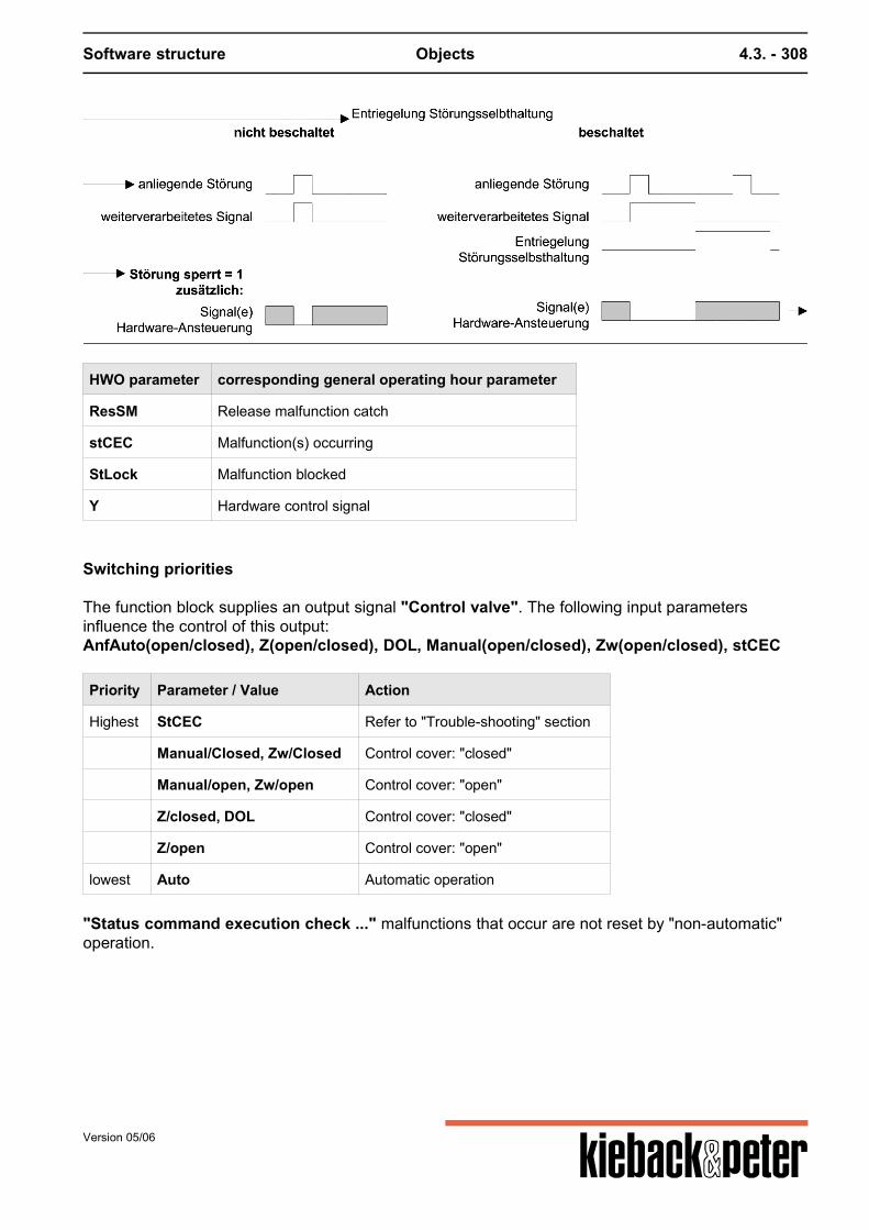
Software structure Objects 4.3. - 308
HWO parameter corresponding general operating hour parameter
ResSM Release malfunction catch
stCEC Malfunction(s) occurring
StLock Malfunction blocked
Y Hardware control signal
Switching priorities
The function block supplies an output signal "Control valve". The following input parametersinfluence the control of this output:AnfAuto(open/closed), Z(open/closed), DOL, Manual(open/closed), Zw(open/closed), stCEC
Priority Parameter / Value Action
Highest StCEC Refer to "Trouble-shooting" section
Manual/Closed, Zw/Closed Control cover: "closed"
Manual/open, Zw/open Control cover: "open"
Z/closed, DOL Control cover: "closed"
Z/open Control cover: "open"
lowest Auto Automatic operation
"Status command execution check ..." malfunctions that occur are not reset by "non-automatic"operation.
Version 05/06
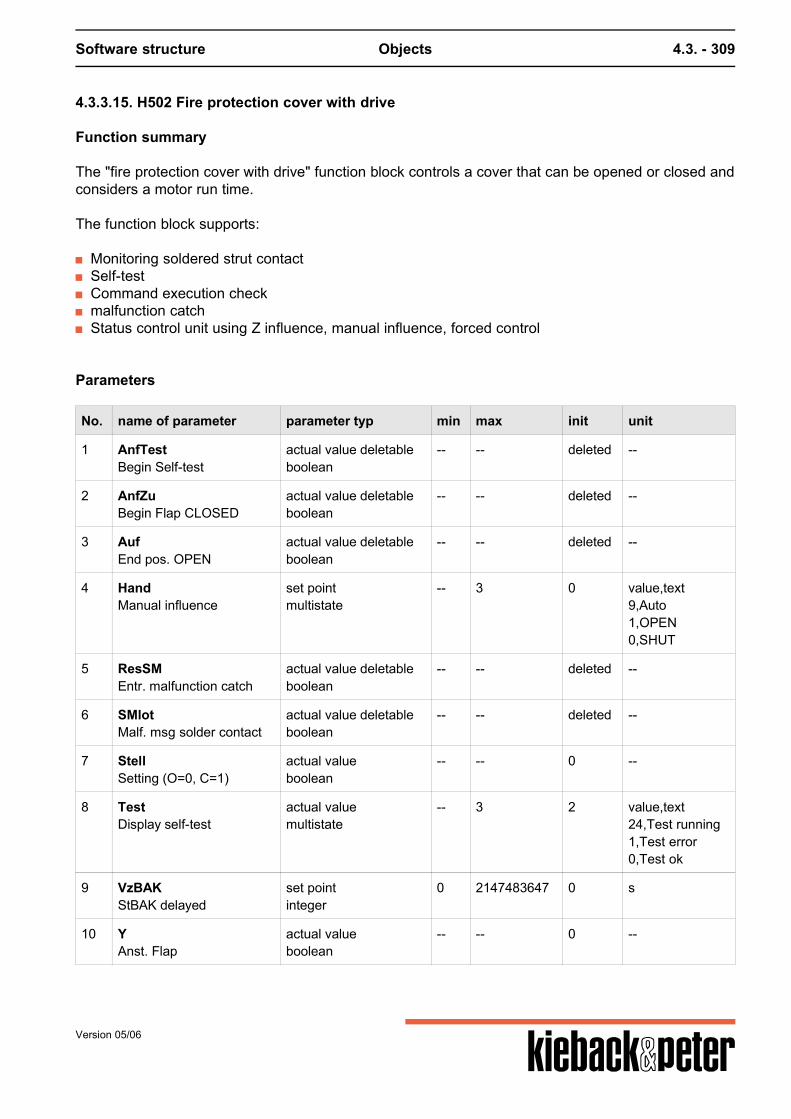
Software structure Objects 4.3. - 309
4.3.3.15. H502 Fire protection cover with drive
Function summary
The "fire protection cover with drive" function block controls a cover that can be opened or closed andconsiders a motor run time.
The function block supports:
Monitoring soldered strut contact Self-test Command execution check malfunction catch Status control unit using Z influence, manual influence, forced control
Parameters
No. name of parameter parameter typ min max init unit
1 AnfTestBegin Self-test
actual value deletableboolean
-- -- deleted --
2 AnfZuBegin Flap CLOSED
actual value deletableboolean
-- -- deleted --
3 AufEnd pos. OPEN
actual value deletableboolean
-- -- deleted --
4 HandManual influence
set pointmultistate
-- 3 0 value,text9,Auto1,OPEN0,SHUT
5 ResSMEntr. malfunction catch
actual value deletableboolean
-- -- deleted --
6 SMlotMalf. msg solder contact
actual value deletableboolean
-- -- deleted --
7 StellSetting (O=0, C=1)
actual valueboolean
-- -- 0 --
8 TestDisplay self-test
actual valuemultistate
-- 3 2 value,text24,Test running1,Test error0,Test ok
9 VzBAKStBAK delayed
set pointinteger
0 2147483647 0 s
10 YAnst. Flap
actual valueboolean
-- -- 0 --
Version 05/06
Software structure Objects 4.3. - 310
No. name of parameter parameter typ min max init unit
11 ZZ- influence
set pointmultistate
-- 3 0 value,text9,Auto1,OPEN0,SHUT
12 Zuto end position
actual value deletableboolean
-- -- deleted --
13 ZwForced control
set pointmultistate
-- 3 0 value,text9,Auto1,OPEN0,SHUT
14 stBAKStatus BAK
actual valueboolean
-- -- 0 --
15 tBAKTime BAK
set pointinteger
0 2147483647 30 s
16 tMotMotor runtime
set pointinteger
0 600 120 s
17 SMoutSMout
actual valueboolean
-- -- 0 --
Function description
In automatic operation the fire protection cover can be controlled using AnfZu.If the final position "closed" is switched and there is no acknowledgement (closed = 1), after thetCEC has ended the command execution check is carried out (stCEC = 1).
This can be used for example to close the fire protection covers at night (e.g. relevant requirementsin Switzerland).If AnfZu is not connected, the position of the fire protection cover can only be changed using Z,manual, Zw and AnfTest.To switch off the fans etc. the SMlot soldered strut contact malfunction message is used.
Monitoring soldered strut contact
If parameter "malfunction message soldered strut contact" goes to 1, the "setting" output is setto "closed".
Self-test
The self-test is started if AnfZu is 0 or is not switched and "request self-test" goes to 1.During the self-test "display self-test" is set to "running".The cover is first moved to ("control cover"=0). The cover is only opened again if there is aacknowledgement (Closed=1) for a switched "closed" parameter or the motor run time (tMot) andthen the "tBaktime" has run out.
Version 05/06
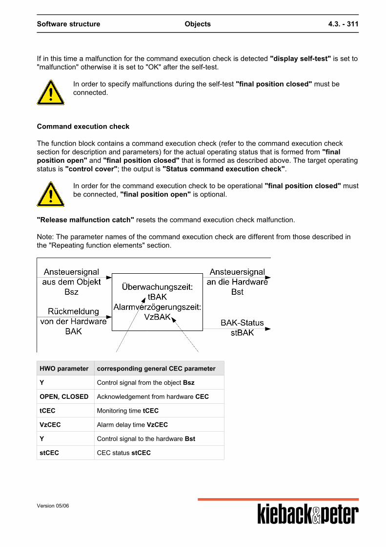
Software structure Objects 4.3. - 311
If in this time a malfunction for the command execution check is detected "display self-test" is set to"malfunction" otherwise it is set to "OK" after the self-test.
In order to specify malfunctions during the self-test "final position closed" must beconnected.
Command execution check
The function block contains a command execution check (refer to the command execution checksection for description and parameters) for the actual operating status that is formed from "finalposition open" and "final position closed" that is formed as described above. The target operatingstatus is "control cover"; the output is "Status command execution check".
In order for the command execution check to be operational "final position closed" mustbe connected, "final position open" is optional.
"Release malfunction catch" resets the command execution check malfunction. Note: The parameter names of the command execution check are different from those described inthe "Repeating function elements" section.
HWO parameter corresponding general CEC parameter
Y Control signal from the object Bsz
OPEN, CLOSED Acknowledgement from hardware CEC
tCEC Monitoring time tCEC
VzCEC Alarm delay time VzCEC
Y Control signal to the hardware Bst
stCEC CEC status stCEC
Version 05/06
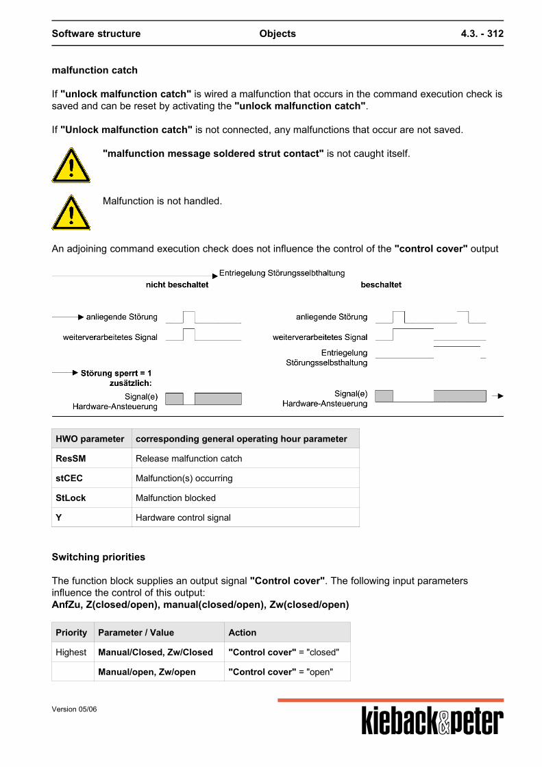
Software structure Objects 4.3. - 312
malfunction catch
If "unlock malfunction catch" is wired a malfunction that occurs in the command execution check issaved and can be reset by activating the "unlock malfunction catch". If "Unlock malfunction catch" is not connected, any malfunctions that occur are not saved.
"malfunction message soldered strut contact" is not caught itself.
Malfunction is not handled.
An adjoining command execution check does not influence the control of the "control cover" output
HWO parameter corresponding general operating hour parameter
ResSM Release malfunction catch
stCEC Malfunction(s) occurring
StLock Malfunction blocked
Y Hardware control signal
Switching priorities
The function block supplies an output signal "Control cover". The following input parametersinfluence the control of this output:AnfZu, Z(closed/open), manual(closed/open), Zw(closed/open)
Priority Parameter / Value Action
Highest Manual/Closed, Zw/Closed "Control cover" = "closed"
Manual/open, Zw/open "Control cover" = "open"
Version 05/06

Software structure Objects 4.3. - 313
Priority Parameter / Value Action
Z/closed "Control cover" = "closed"
Z/open "Control cover" = "open"
AnfTest Self-test
lowest Auto Automatic operation
"Status command execution check ..." malfunctions that occur are not reset by "non-automatic"operation.Forced is prioritized higher than Z. Therefore this cover can be used as a butterfly valve (e.g. with asmoke alarm).
Version 05/06
Software structure Objects 4.3. - 314
4.3.3.16. H503 Cover 3-point
Function summary
The "3-point cover" function block controls a 3-point cover using an analog signal (0..0.100%). The function block supports:
Idle zone Malfunction catch / malfunction handling Status control unit using Z influence, DOL, manual influence, forced control
The "3-point cover" function block controls a 3-point cover using an analog signal (0..00.100 %). Ifthe value of the Y output is to be increased an OPEN pulse is created. If the Y signal is to bereduced, a CLOSE pulse is created. Independent of a set idle zone above 97% an ongoing OPENsignal and under 3% an ongoing CLOSE signal is issued.The length of the OPEN and CLOSE pulses are calculated from the value of the change in the Youtput and the motor operating times tMotAuf or tMotZu. The hardware object can be used for 3-point actuators with and without position feedback signal. If no position feedback signal is availablethe input values "final position open" or "final position CLOSED" are analyzed for thesynchronization.When the final positions are reached (for entered sources for open and close final positions) the drivemoves to "stop" until it receives a command in the opposite direction < 97% or > 3%.
Parameters
No. name of parameter parameter typ min max init unit
1 AufEnd pos. OPEN
actual value deletableboolean
-- -- deleted --
2 DBEDirect operating level active
actual value deletableboolean
-- -- deleted --
3 HandManual influence
set point deletableinteger
0 100 deleted %
4 ResSMEntr. malfunction catch
actual value deletableboolean
-- -- deleted --
5 SMMalf. with flap
actual value deletableboolean
-- -- deleted --
6 StSperrMalfunction blocked
set pointboolean
-- -- 0 --
7 TotSignal change deadzone
set pointinteger
0 50 0 %
8 YSetp. flap
actual valueinteger
0 100 0 %
9 YAufOPEN Impulse
actual valueboolean
-- -- 0 --
Version 05/06
Software structure Objects 4.3. - 315
No. name of parameter parameter typ min max init unit
10 YZuCLOSED Impulse
actual valueboolean
-- -- 0 --
11 YistPosition display
actual valueinteger
0 100 0 %
12 YrServo feedback of flap
actual value deletableinteger
0 100 deleted %
13 YsollSetp. flap
set pointinteger
0 100 0 %
14 ZZ- influence
set point deletableinteger
0 100 deleted %
15 ZuEnd pos. SHUT
actual value deletableboolean
-- -- deleted --
16 ZwForced control
set point deletableboolean
-- -- deleted --
17 ZwSwSetp- flap forced control
set pointinteger
0 100 100 %
18 tMotAufMotor runtime OPEN
set pointinteger
0 2147483647 120 s
19 tMotZuMotor runtime CLOSED
set pointinteger
0 2147483647 120 s
20 SMoutSMout
actual valueboolean
-- -- 0 --
Function description
Position display
There is a "position display" output. This indicates this value if the "position feedback signalcover" input is occupied. If this acknowledgement is not occupied the value of the "target positioncover" is used. This may come from "Target cover position in automatic operation", "Zinfluence", "set point forced control" or "manual influence", i.e. from the input with the highestactive priority.
Idle zone
If the "position feedback signal cover" is not switched on the "idle zone" only works on controlsignal changes if the control signal (Ytarget) changes by a higher amount than the idle zone set. If"position feedback signal cover" is switched the idle zone works on the difference between thecontrol signal and the position feedback signal (Yr). I.e. if the difference reaches a higher amountthan the idle zone set, signal changes are issued.
Version 05/06
Software structure Objects 4.3. - 316
Malfunction catch / malfunction handling
If "unlock malfunction catch" is wired malfunctions that occur are saved and can be reset byactivating the "unlock malfunction catch".A malfunction that occurs SM may not influence the control of outputYa) not ("malfunction blocked" = 0)b) sets the output Y to 0% ("malfunction blocked" = 1)If a malfunction sets the output Y to 0% this can only be reset by activating the "Unlock malfunctioncatch".If "unlock malfunction catch" is not wired malfunctions that occur are not saved, i.e. if themalfunction disappears the malfunction handling disappears.
Switching priorities
The function block supplies an output signal "Target setting valve". The following input parametersinfluence the control of this output:Ytarget, Z, DOL, Manual, Zw and ZwSw, SM
Priority Parameter / Value Action
Highest SM See "effects of malfunctions on operating behavior" section.
Zw Y = ZwSw
Manual Y = Manual
DOL Y = 0%
Z Y = Z
lowest Auto Y = Ytarget
Version 05/06
Software structure Objects 4.3. - 317
4.3.3.17. H504 Cover constant
Function summary
The "cover constant" function block controls a constant cover with target setting of 0..100%.The function block supports:
Trouble-shooting Status control unit using Z influence, DOL, manual influence, forced control
Parameters
No. name of parameter parameter typ min max init unit
1 AufEnd pos. OPEN
actual value deletableboolean
-- -- deleted --
2 ZuEnd pos. SHUT
actual value deletableboolean
-- -- deleted --
3 YsollSetp. flap automatic
actual valuefloat
0 100 0 %
4 YrServo back flap
actual value deletablefloat
0 100 deleted %
5 YistSetting no.
actual valuefloat
0 100 0 %
6 YSetp. flap
actual valuefloat
0 100 0 %
9 DBEDBE Status
actual value deletableboolean
-- -- deleted --
10 HandManual influence
set point deletableinteger
0 100 deleted %
14 ResSMEnter malf. msg
set point deletableboolean
-- -- deleted --
15 SMMalf. with flap
actual value deletableboolean
-- -- deleted --
16 StSperrMalfunction blocked
set pointboolean
-- -- 0 --
18 ZZ- influence
set point deletableinteger
0 100 deleted %
19 ZwForced control
actual value deletableboolean
-- -- deleted --
20 ZwSwSetp. flap forced control
set pointinteger
0 100 100 %
Version 05/06

Software structure Objects 4.3. - 318
No. name of parameter parameter typ min max init unit
21 SMoutSMout
actual valueboolean
-- -- 0 --
Function description
Position display
There is a "position display" output. This indicates this value if the "position feedback signalcover" input is occupied. If this acknowledgement is not occupied the value of the "target positioncover" is used. This may come from "Target cover position inautomatic operation" ,"Z influence", "set point forced control" or "manual influence", i.e. fromthe input with the highest active priority.
Malfunction catch / malfunction handling
If "unlock malfunction catch" is wired malfunctions that occur are saved and can be reset byactivating the "unlock malfunction catch". A malfunction that occurs SM may not influence the control of outputY a) not ("malfunction blocked" = 0)b) sets the output Y to 0% ("malfunction blocked" = 1) If a malfunction sets the output Y to 0% this can only be reset by activating the "Unlock malfunctioncatch". If "Unlock malfunction catch" is not connected, any malfunctions that occur are not savedi.e. if the malfunction disappears the trouble-shooting is stopped.
HWO parameter corresponding general operating hour parameter
ResSM Release malfunction catch
SMstCEC
Malfunction(s) occurring
Version 05/06
Software structure Objects 4.3. - 319
HWO parameter corresponding general operating hour parameter
StLock Malfunction blocked
Y Hardware control signal
Switching priorities
The function block supplies an output signal "Target setting valve". The following input parametersinfluence the control of this output:Ytarget, Z, DOL, Manual, Zw and ZwSw, SM
Priority Parameter / Value Action
Highest SM See "effects of malfunctions on operating behavior" section.
Zw Y = ZwSw
Manual Y = Manual
DOL Y = 0%
Z Y = Z
lowest Auto Y = Ytarget
Version 05/06
Software structure Objects 4.3. - 320
4.3.3.18. H601 Fan single stage
Function summary
The "fan single stage" function block controls a single-stage fan and supports:
cover control during the warm-up phase / request for control Operating hours / limiting value Switching delays Command execution check Malfunction catch / malfunction handling Status control unit using Z influence, DOL, manual influence, repair switch, forced control
Parameters
No. name of parameter parameter typ min max init unit
1 AnfAutoBegin Automatic
actual value deletableboolean
-- -- deleted --
2 AnfKlBegin Flap
actual valueboolean
-- -- 0 --
3 AnlVerzStart delay Automatic
set pointinteger
0 2147483647 0 s
4 BMKlAufPlant msg: Flap OPEN
actual value deletableboolean
-- -- deleted --
5 BMLuPlant msg: Fan
actual value deletableboolean
-- -- deleted --
6 BhOperating hours
set pointinteger
0 2147483647 0 h
7 BhAktivActivate oper.hrs. counting
set pointboolean
-- -- 0 --
8 BhGwOper.hrs. limit value
set pointinteger
0 2147483647 0 h
9 DBEDirect operating level active
actual value deletableboolean
-- -- deleted --
10 HandManual switch
set pointmultistate
-- 3 0 value,text9,Auto0,Off1,On
11 LEinFan ON
actual valueboolean
-- -- 0 --
12 RepRepair switch
actual value deletableboolean
-- -- deleted --
Version 05/06
Software structure Objects 4.3. - 321
No. name of parameter parameter typ min max init unit
13 ResBhReset opr. hours
actual value deletableboolean
-- -- deleted --
14 ResSMEntr. malfunction catch
actual value deletableboolean
-- -- deleted --
15 SMFan malf.
actual value deletableboolean
-- -- deleted --
16 StSperrMalfunction blocked
set pointboolean
-- -- 0 --
17 VzBAKstBAK delayed
set pointinteger
0 2147483647 0 s
18 ZZ- influence
set pointmultistate
-- 3 0 value,text9,Auto0,Off1,On
19 ZwForced control
set pointmultistate
-- 3 0 value,text9,Auto0,Off1,On
20 gBhLimit value error by opr.hrs.
actual valueboolean
-- -- 0 --
21 regBegin Control
actual valueboolean
-- -- 0 --
22 stBAKStatus BAK Fan
actual valueboolean
-- -- 0 --
23 tBAKDelay BAK
set pointinteger
0 2147483647 30 s
24 SMoutSMout
actual valueboolean
-- -- 0 --
Function description
cover control during the warm-up phase / request for control
If the fan is to be switched on the "cover request" is first set to 1.Then there is a pause for the "operational cover open" = 1 if this input is wired. Then "fan on" isset to 1 and - if connected - the plant waits for "fan operating message" = 1. Only then is "requestcontrol" set to 1.
For "operational message cover open" this does not include a command executioncheck as "request pump / cover" should always be linked to a "cover" hardware objectthat contains its own command execution check.
Version 05/06
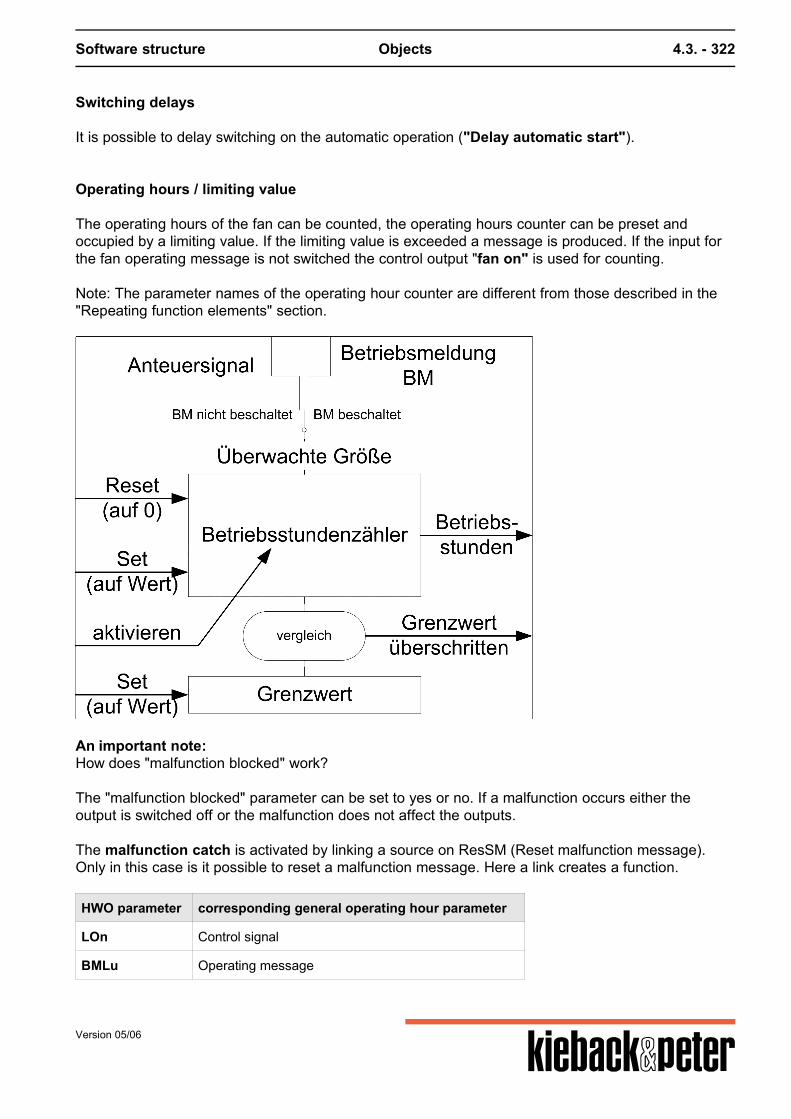
Software structure Objects 4.3. - 322
Switching delays
It is possible to delay switching on the automatic operation ("Delay automatic start").
Operating hours / limiting value
The operating hours of the fan can be counted, the operating hours counter can be preset andoccupied by a limiting value. If the limiting value is exceeded a message is produced. If the input forthe fan operating message is not switched the control output "fan on" is used for counting. Note: The parameter names of the operating hour counter are different from those described in the"Repeating function elements" section.
An important note:How does "malfunction blocked" work? The "malfunction blocked" parameter can be set to yes or no. If a malfunction occurs either theoutput is switched off or the malfunction does not affect the outputs. The malfunction catch is activated by linking a source on ResSM (Reset malfunction message).Only in this case is it possible to reset a malfunction message. Here a link creates a function.
HWO parameter corresponding general operating hour parameter
LOn Control signal
BMLu Operating message
Version 05/06
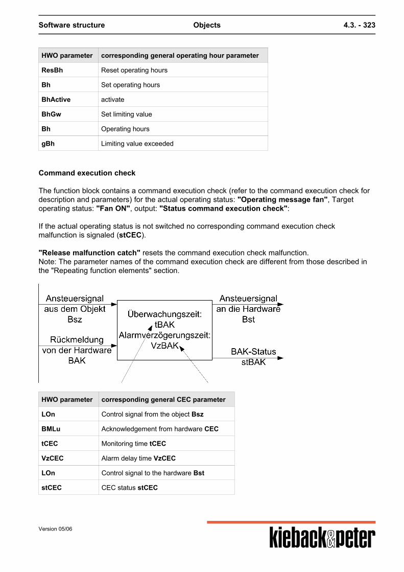
Software structure Objects 4.3. - 323
HWO parameter corresponding general operating hour parameter
ResBh Reset operating hours
Bh Set operating hours
BhActive activate
BhGw Set limiting value
Bh Operating hours
gBh Limiting value exceeded
Command execution check
The function block contains a command execution check (refer to the command execution check fordescription and parameters) for the actual operating status: "Operating message fan", Targetoperating status: "Fan ON", output: "Status command execution check": If the actual operating status is not switched no corresponding command execution checkmalfunction is signaled (stCEC). "Release malfunction catch" resets the command execution check malfunction.Note: The parameter names of the command execution check are different from those described inthe "Repeating function elements" section.
HWO parameter corresponding general CEC parameter
LOn Control signal from the object Bsz
BMLu Acknowledgement from hardware CEC
tCEC Monitoring time tCEC
VzCEC Alarm delay time VzCEC
LOn Control signal to the hardware Bst
stCEC CEC status stCEC
Version 05/06
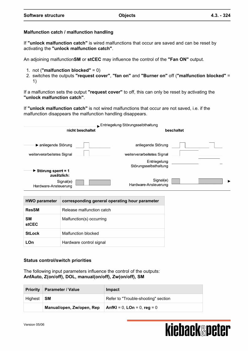
Software structure Objects 4.3. - 324
Malfunction catch / malfunction handling
If "unlock malfunction catch" is wired malfunctions that occur are saved and can be reset byactivating the "unlock malfunction catch". An adjoining malfunctionSM or stCEC may influence the control of the "Fan ON" output.
1. not ("malfunction blocked" = 0)2. switches the outputs "request cover", "fan on" and "Burner on" off ("malfunction blocked" =
1)
If a malfunction sets the output "request cover" to off, this can only be reset by activating the"unlock malfunction catch". If "unlock malfunction catch" is not wired malfunctions that occur are not saved, i.e. if themalfunction disappears the malfunction handling disappears.
HWO parameter corresponding general operating hour parameter
ResSM Release malfunction catch
SMstCEC
Malfunction(s) occurring
StLock Malfunction blocked
LOn Hardware control signal
Status control/switch priorities
The following input parameters influence the control of the outputs:AnfAuto, Z(on/off), DOL, manual(on/off), Zw(on/off), SM
Priority Parameter / Value Impact
Highest SM Refer to "Trouble-shooting" section
Manual/open, Zw/open, Rep AnfKl = 0, LOn = 0, reg = 0
Version 05/06

Software structure Objects 4.3. - 325
Priority Parameter / Value Impact
Manual/open, Zw/open AnfKl = 1
Z/closed, DOL AnfKl = 0, LOn = 0, reg = 0
Z/On AnfKl = 1
lowest Auto Automatic operation, "request valve" = AnfAuto
"Status command execution check ..." malfunctions that occur are not reset by "non-automatic"operation.
Version 05/06
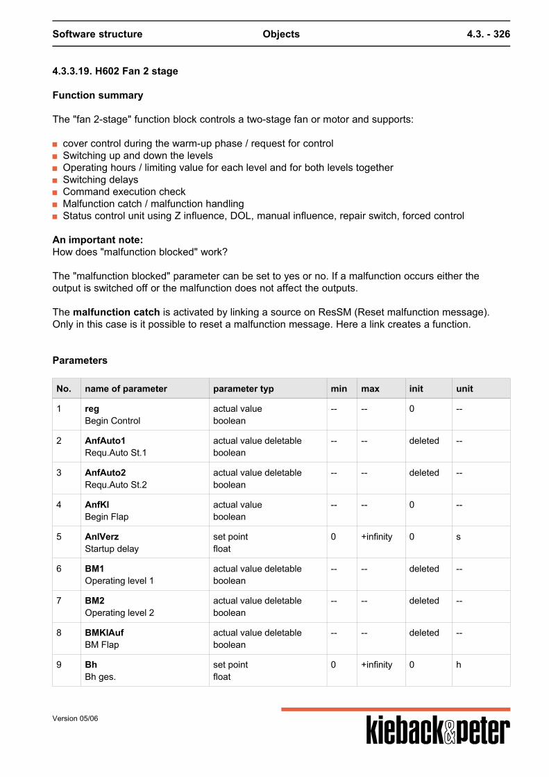
Software structure Objects 4.3. - 326
4.3.3.19. H602 Fan 2 stage
Function summary
The "fan 2-stage" function block controls a two-stage fan or motor and supports:
cover control during the warm-up phase / request for control Switching up and down the levels Operating hours / limiting value for each level and for both levels together Switching delays Command execution check Malfunction catch / malfunction handling Status control unit using Z influence, DOL, manual influence, repair switch, forced control
An important note:How does "malfunction blocked" work? The "malfunction blocked" parameter can be set to yes or no. If a malfunction occurs either theoutput is switched off or the malfunction does not affect the outputs. The malfunction catch is activated by linking a source on ResSM (Reset malfunction message).Only in this case is it possible to reset a malfunction message. Here a link creates a function.
Parameters
No. name of parameter parameter typ min max init unit
1 regBegin Control
actual valueboolean
-- -- 0 --
2 AnfAuto1Requ.Auto St.1
actual value deletableboolean
-- -- deleted --
3 AnfAuto2Requ.Auto St.2
actual value deletableboolean
-- -- deleted --
4 AnfKlBegin Flap
actual valueboolean
-- -- 0 --
5 AnlVerzStartup delay
set pointfloat
0 +infinity 0 s
6 BM1Operating level 1
actual value deletableboolean
-- -- deleted --
7 BM2Operating level 2
actual value deletableboolean
-- -- deleted --
8 BMKlAufBM Flap
actual value deletableboolean
-- -- deleted --
9 BhBh ges.
set pointfloat
0 +infinity 0 h
Version 05/06
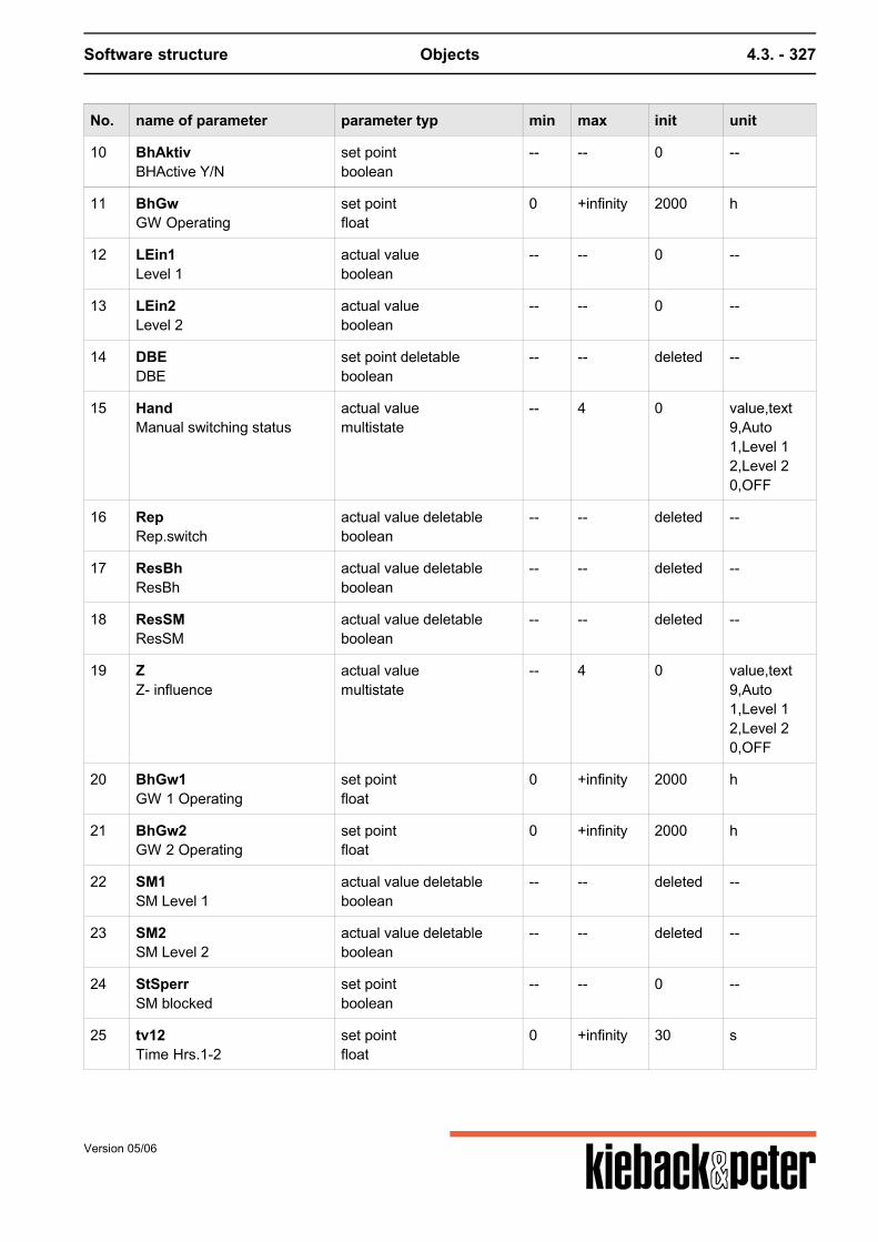
Software structure Objects 4.3. - 327
No. name of parameter parameter typ min max init unit
10 BhAktivBHActive Y/N
set pointboolean
-- -- 0 --
11 BhGwGW Operating
set pointfloat
0 +infinity 2000 h
12 LEin1Level 1
actual valueboolean
-- -- 0 --
13 LEin2Level 2
actual valueboolean
-- -- 0 --
14 DBEDBE
set point deletableboolean
-- -- deleted --
15 HandManual switching status
actual valuemultistate
-- 4 0 value,text9,Auto1,Level 12,Level 20,OFF
16 RepRep.switch
actual value deletableboolean
-- -- deleted --
17 ResBhResBh
actual value deletableboolean
-- -- deleted --
18 ResSMResSM
actual value deletableboolean
-- -- deleted --
19 ZZ- influence
actual valuemultistate
-- 4 0 value,text9,Auto1,Level 12,Level 20,OFF
20 BhGw1GW 1 Operating
set pointfloat
0 +infinity 2000 h
21 BhGw2GW 2 Operating
set pointfloat
0 +infinity 2000 h
22 SM1SM Level 1
actual value deletableboolean
-- -- deleted --
23 SM2SM Level 2
actual value deletableboolean
-- -- deleted --
24 StSperrSM blocked
set pointboolean
-- -- 0 --
25 tv12Time Hrs.1-2
set pointfloat
0 +infinity 30 s
Version 05/06
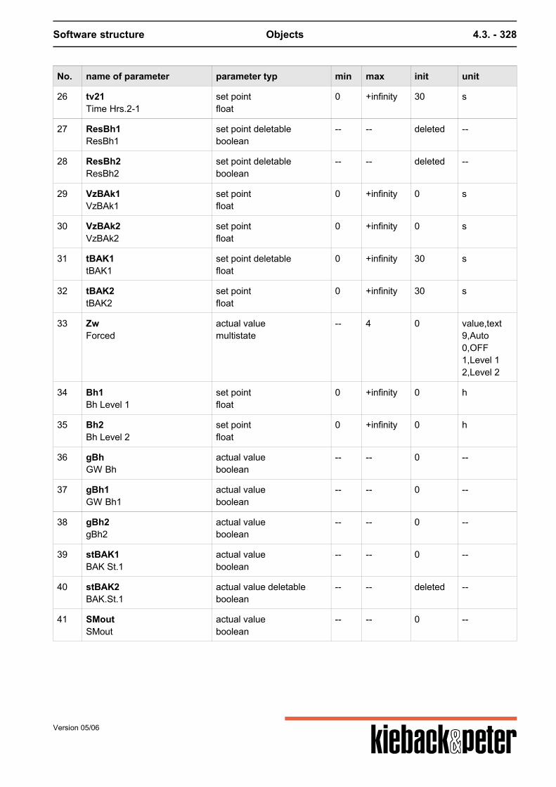
Software structure Objects 4.3. - 328
No. name of parameter parameter typ min max init unit
26 tv21Time Hrs.2-1
set pointfloat
0 +infinity 30 s
27 ResBh1ResBh1
set point deletableboolean
-- -- deleted --
28 ResBh2ResBh2
set point deletableboolean
-- -- deleted --
29 VzBAk1VzBAk1
set pointfloat
0 +infinity 0 s
30 VzBAk2VzBAk2
set pointfloat
0 +infinity 0 s
31 tBAK1tBAK1
set point deletablefloat
0 +infinity 30 s
32 tBAK2tBAK2
set pointfloat
0 +infinity 30 s
33 ZwForced
actual valuemultistate
-- 4 0 value,text9,Auto0,OFF1,Level 12,Level 2
34 Bh1Bh Level 1
set pointfloat
0 +infinity 0 h
35 Bh2Bh Level 2
set pointfloat
0 +infinity 0 h
36 gBhGW Bh
actual valueboolean
-- -- 0 --
37 gBh1GW Bh1
actual valueboolean
-- -- 0 --
38 gBh2gBh2
actual valueboolean
-- -- 0 --
39 stBAK1BAK St.1
actual valueboolean
-- -- 0 --
40 stBAK2BAK.St.1
actual value deletableboolean
-- -- deleted --
41 SMoutSMout
actual valueboolean
-- -- 0 --
Version 05/06
Software structure Objects 4.3. - 329
Function description
cover control during the warm-up phase / request for control
If the fan is to be switched on the "cover request" is first set to 1.Then there is a pause for the "operational cover open" = 1 if this input is wired. Then "fan on level 1" is set to 1 and - if connected - the plant waits for "fan operating message" =1. Only then is "request control" set to 1. If fan level should start the process described takes place for level 2. "Request control" open is set to 1 when "fan on level 1" or "fan on level 2" is switched on and theoperating messages. "Request control" also remains when switching between the levels. If theplant switches from level 1 to level 2 the plant waits for "VzBAk2". If the operating message for level2 is not yet available the "request control" is set to "0" again. If the output "Fan ON level 2" is active the output "Fan ON level 1" is blocked (mutual locking). This HWO does not work with fans that have to be switched to both level 1 and level 2 at the sametime.
For "operational message cover open" this does not include a command executioncheck as "request pump / cover" should always be linked to a "cover" hardware objectthat contains its own command execution check.
Switching up and down the levels
Level 2 is always switched on with a time delay ("switching up delay") via level 1, i.e. level 1 mustrun for a "Switching up delay time" before level 2 is switched on. This is independent of "warm-updelay automatic level 1".
If the request for level 2 is placed when level 1 has already been active longer than "Switching updelay" level 2 is activated immediately ("Switching up delay" is to be viewed as a minimum time forlevel 1). Switching back from level 2 to level 1 occurs via an off phase for the "switching down" period.Switching up and down the levels does not work in non-automatic modes, i.e. for Z, manual andforced.
When switching back from level 2 to level 1 the "request control" stays set to 1 evenwithin the "switching down time".
Version 05/06
Software structure Objects 4.3. - 330
Switching delays
The fan can be switched on in automatic mode with a delay for each level.If AnfAuto1 is activated the plant first waits for "warm-up delay automatic level 1"before the warm-up phase starts. Then comes:"Request cover"
"Operational message cover open""Fan on level 1". If level AnfAuto2 is activated in ongoing operation the plant first waits until the "switching up delay"has ended for level 1 and only then switches on "fan on level 2".If in the off status AnfAuto2 is activated first the plant first waits for "warm-up delay automatic level1" before the warm-up phase starts. Then comes:"Request cover""Operational message cover open""Fan on level 1"."Switching up delay" and"Fan on level 2"."warm-up delay automatic level 1" is only considered in automatic operation.
Operating hours / limiting value
The fan's operating hours can be counted for each level individually and also for both levels together;the operating counters can be preset and given a limiting value. If the limiting value is exceeded amessage is produced. If the inputs of the fan fan operating messages are not connected, thecorresponding control output "fan on level 1" or "fan on level" are used for counting. Note: The parameter names of the operating hour counter are different from those described in the"Repeating function elements" section.
Command execution check
The function block contains command execution checks for both levels (refer to command executioncheck chapter for description and parameters) for theActual operational statuses: "operating message fan level 1 or 2"Target operational statuses: "fan ON level 1 or 2"Outputs: "Status command execution check level 1 or 2" If the actual operating statuses are not switched, no corresponding command execution checkmalfunction is signaled (stCEC level 1 or 2). "Release malfunction catch" resets the command execution check malfunction. Note: The parameter names of the command execution check are different from those described inthe "Repeating function elements" section.
Version 05/06
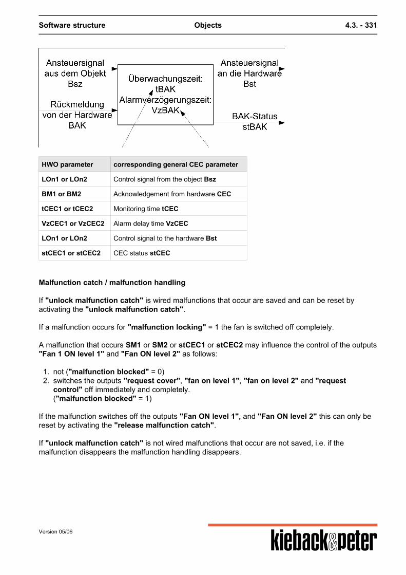
Software structure Objects 4.3. - 331
HWO parameter corresponding general CEC parameter
LOn1 or LOn2 Control signal from the object Bsz
BM1 or BM2 Acknowledgement from hardware CEC
tCEC1 or tCEC2 Monitoring time tCEC
VzCEC1 or VzCEC2 Alarm delay time VzCEC
LOn1 or LOn2 Control signal to the hardware Bst
stCEC1 or stCEC2 CEC status stCEC
Malfunction catch / malfunction handling
If "unlock malfunction catch" is wired malfunctions that occur are saved and can be reset byactivating the "unlock malfunction catch". If a malfunction occurs for "malfunction locking" = 1 the fan is switched off completely. A malfunction that occurs SM1 or SM2 or stCEC1 or stCEC2 may influence the control of the outputs"Fan 1 ON level 1" and "Fan ON level 2" as follows:
1. not ("malfunction blocked" = 0)2. switches the outputs "request cover", "fan on level 1", "fan on level 2" and "request
control" off immediately and completely.("malfunction blocked" = 1)
If the malfunction switches off the outputs "Fan ON level 1", and "Fan ON level 2" this can only bereset by activating the "release malfunction catch". If "unlock malfunction catch" is not wired malfunctions that occur are not saved, i.e. if themalfunction disappears the malfunction handling disappears.
Version 05/06
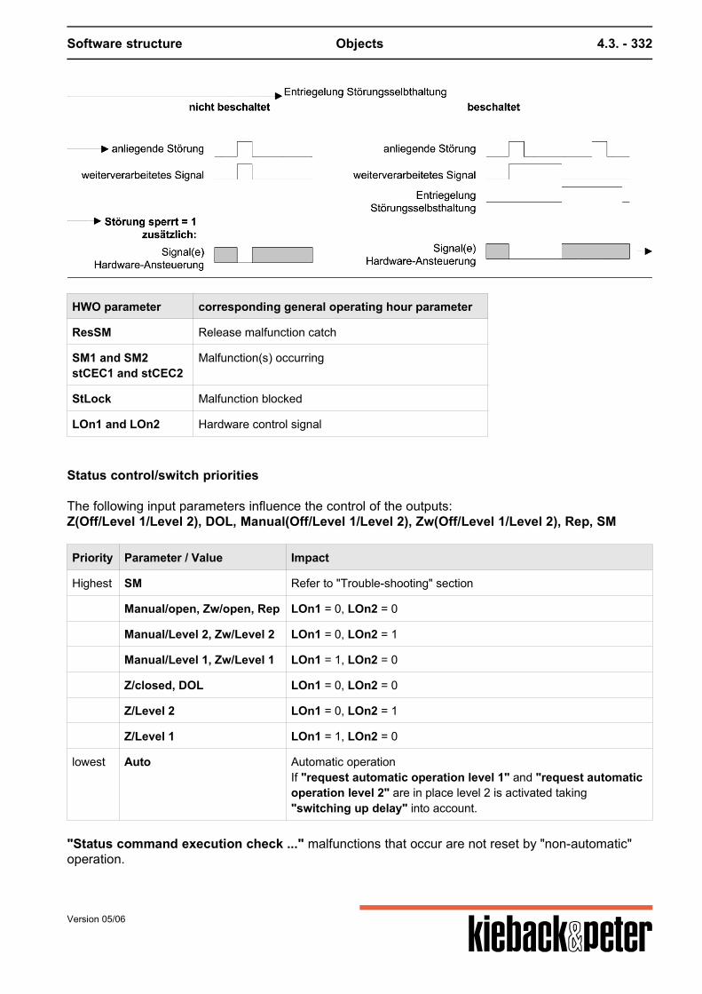
Software structure Objects 4.3. - 332
HWO parameter corresponding general operating hour parameter
ResSM Release malfunction catch
SM1 and SM2stCEC1 and stCEC2
Malfunction(s) occurring
StLock Malfunction blocked
LOn1 and LOn2 Hardware control signal
Status control/switch priorities
The following input parameters influence the control of the outputs:Z(Off/Level 1/Level 2), DOL, Manual(Off/Level 1/Level 2), Zw(Off/Level 1/Level 2), Rep, SM
Priority Parameter / Value Impact
Highest SM Refer to "Trouble-shooting" section
Manual/open, Zw/open, Rep LOn1 = 0, LOn2 = 0
Manual/Level 2, Zw/Level 2 LOn1 = 0, LOn2 = 1
Manual/Level 1, Zw/Level 1 LOn1 = 1, LOn2 = 0
Z/closed, DOL LOn1 = 0, LOn2 = 0
Z/Level 2 LOn1 = 0, LOn2 = 1
Z/Level 1 LOn1 = 1, LOn2 = 0
lowest Auto Automatic operationIf "request automatic operation level 1" and "request automaticoperation level 2" are in place level 2 is activated taking"switching up delay" into account.
"Status command execution check ..." malfunctions that occur are not reset by "non-automatic"operation.
Version 05/06

Software structure Objects 4.3. - 333
Version 05/06

Software structure Objects 4.3. - 334
4.3.3.21. H604 fan constant FC/bypass
Function summary
The "fan constant" function block controls a fan or motor with an optional bypass switch as per a setpoint Ytarget and supports:
cover control during the warm-up phase / request for control Operating hours / limiting value Switching delays Command execution check Malfunction catch / malfunction handling Status control unit using Z influence, DOL, manual influence, repair switch, forced control
Parameters
No. name of parameter parameter typ min max init unit
1 AnfAutoBegin Automatic
actual value deletableboolean
-- -- deleted --
2 AnfKlBegin Flap
actual valueboolean
-- -- 0 --
3 AnlVerzStart delay Automatic
set pointinteger
0 2147483647 0 s
4 BMRe: fan message
actual value deletableboolean
-- -- deleted --
5 BMFuRe: message FU
actual value deletableboolean
-- -- deleted --
6 BMKlAufRe: flap OPEN message
actual value deletableboolean
-- -- deleted --
7 BhOperating hours
set pointinteger
0 2147483647 0 h
8 BhAktivRe: Activate oper.hrs. counting
set pointboolean
-- -- 0 --
9 BhGwOper.hrs. limit value
set pointinteger
0 2147483647 0 h
10 ByAktivBypass activation
set pointboolean
-- -- 0 --
11 DBEDirect operating level active
actual value deletableboolean
-- -- deleted --
Version 05/06
Software structure Objects 4.3. - 335
No. name of parameter parameter typ min max init unit
12 HandManual switch
set pointmultistate
-- 4 0 value,text9,Auto0,OFF21,FU_ON31,BY_ON
13 LuByFan bypass ON
actual valueboolean
-- -- 0 --
14 LuFuFan FU ON
actual valueboolean
-- -- 0 --
15 RMAnaSetting feedback FU
actual value deletableinteger
0 100 deleted %
16 RepRepare switch
actual value deletableboolean
-- -- deleted --
17 ResBhReset opr. hours
actual value deletableboolean
-- -- deleted --
18 ResSMUnlock malfunction catch
actual value deletableboolean
-- -- deleted --
19 RzByFuSwitch-back time bypass FU
set pointinteger
0 120 30 s
20 SMFan malf.
actual value deletableboolean
-- -- deleted --
21 SMFuMalfunction FU
actual value deletableboolean
-- -- deleted --
22 StFuByMalf. FU requires bypass
set pointboolean
-- -- 0 --
23 StFuSperMalf. FU blocked
set pointboolean
-- -- 0 --
24 StSperrMalf. fan blocked
set pointboolean
-- -- 0 --
25 VzBAKstBAK delayed
set pointinteger
0 2147483647 0 s
26 VzBAKFustBAKFu delayed
set pointinteger
0 2147483647 0 s
27 YFU Drive analog
actual valueinteger
0 100 0 %
28 YsollFan setpoint
set pointinteger
0 100 0 %
Version 05/06
Software structure Objects 4.3. - 336
No. name of parameter parameter typ min max init unit
29 ZZ- influence
set pointmultistate
-- 4 0 value,text9,Auto0,OFF21,FU_ON31,BY_ON
30 ZsSetp. fan Z-influence
set pointinteger
0 100 0 %
31 ZwForced control
set pointmultistate
-- 3 0 value,text9,Auto0,OFF1,ON
32 ZwSwSetp. forced control analog
set pointinteger
0 100 0 %
33 gBhLimit value error by opr.hrs.
actual valueboolean
-- -- 0 --
34 regBegin Control
actual valueboolean
-- -- 0 --
35 stBAKStatus BAK Fan
actual valueboolean
-- -- 0 --
36 stBAKFuStatus BAK FU
actual valueboolean
-- -- 0 --
37 tBAKTime stBAK
set pointinteger
0 2147483647 30 s
38 tBAKFuTime stBAKFu
set pointinteger
0 2147483647 30 s
39 SMoutSMout
actual valueboolean
-- -- 0 --
Function description
Bypass
The optional bypass branch secures fan operation; if a frequency converter malfunction occurs thefan runs without control in this case. The outputs "fan FC ON" and "fan bypass ON" are neveractive at the same time. The bypass function is switched on or off with parameter ByAktiv.A source can be linked and used toconsciously switch the bypass on.
Version 05/06
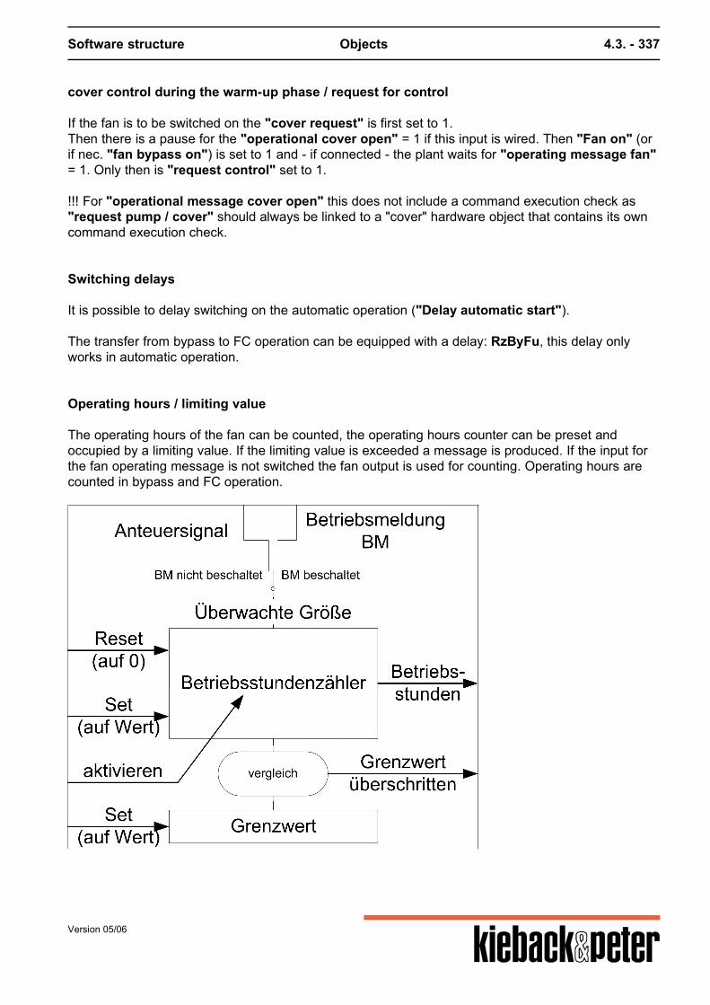
Software structure Objects 4.3. - 337
cover control during the warm-up phase / request for control
If the fan is to be switched on the "cover request" is first set to 1.Then there is a pause for the "operational cover open" = 1 if this input is wired. Then "Fan on" (orif nec. "fan bypass on") is set to 1 and - if connected - the plant waits for "operating message fan"= 1. Only then is "request control" set to 1. !!! For "operational message cover open" this does not include a command execution check as"request pump / cover" should always be linked to a "cover" hardware object that contains its owncommand execution check.
Switching delays
It is possible to delay switching on the automatic operation ("Delay automatic start").
The transfer from bypass to FC operation can be equipped with a delay: RzByFu, this delay onlyworks in automatic operation.
Operating hours / limiting value
The operating hours of the fan can be counted, the operating hours counter can be preset andoccupied by a limiting value. If the limiting value is exceeded a message is produced. If the input forthe fan operating message is not switched the fan output is used for counting. Operating hours arecounted in bypass and FC operation.
Version 05/06
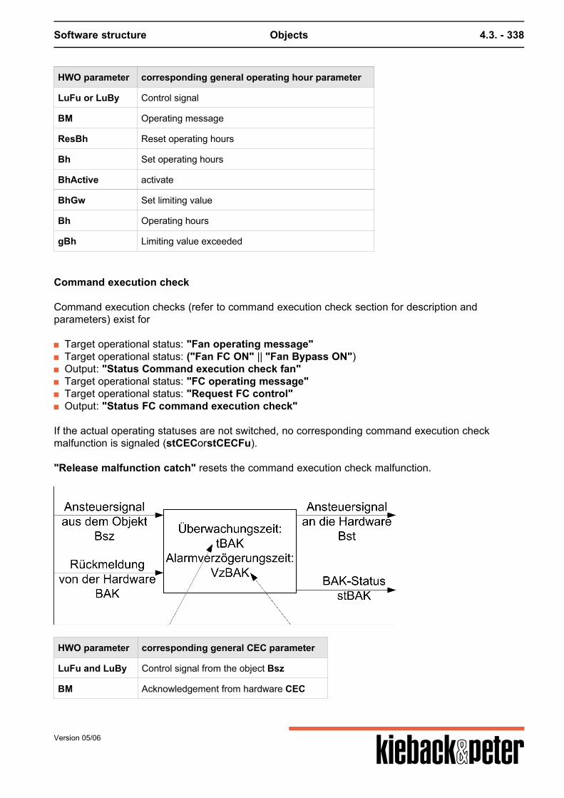
Software structure Objects 4.3. - 338
HWO parameter corresponding general operating hour parameter
LuFu or LuBy Control signal
BM Operating message
ResBh Reset operating hours
Bh Set operating hours
BhActive activate
BhGw Set limiting value
Bh Operating hours
gBh Limiting value exceeded
Command execution check
Command execution checks (refer to command execution check section for description andparameters) exist for
Target operational status: "Fan operating message" Target operational status: ("Fan FC ON" || "Fan Bypass ON") Output: "Status Command execution check fan" Target operational status: "FC operating message" Target operational status: "Request FC control" Output: "Status FC command execution check"
If the actual operating statuses are not switched, no corresponding command execution checkmalfunction is signaled (stCECorstCECFu). "Release malfunction catch" resets the command execution check malfunction.
HWO parameter corresponding general CEC parameter
LuFu and LuBy Control signal from the object Bsz
BM Acknowledgement from hardware CEC
Version 05/06
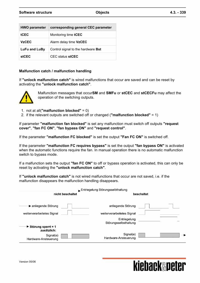
Software structure Objects 4.3. - 339
HWO parameter corresponding general CEC parameter
tCEC Monitoring time tCEC
VzCEC Alarm delay time VzCEC
LuFu and LuBy Control signal to the hardware Bst
stCEC CEC status stCEC
Malfunction catch / malfunction handling
If "unlock malfunction catch" is wired malfunctions that occur are saved and can be reset byactivating the "unlock malfunction catch".
Malfunction messages that occurSM and SMFu or stCEC and stCECFu may affect theoperation of the switching outputs.
1. not at all("malfunction blocked" = 0)2. if the relevant outputs are switched off or changed ("malfunction blocked" = 1)
If parameter "malfunction fan blocked" is set any malfunction must switch off outputs "requestcover", "fan FC ON", "fan bypass ON" and "request control".
If the parameter "malfunction FC blocked" is set the output "Fan FC ON" is switched off.
If the parameter "malfunction FC requires bypass" is set the output "fan bypass ON" is activatedwhen the automatic functions require the fan. In manual operation there is no automatic malfunctionswitch to bypass mode. If a malfunction sets the output "fan FC ON" to off or bypass operation is activated, this can only bereset by activating the "unlock malfunction catch". If "unlock malfunction catch" is not wired malfunctions that occur are not saved, i.e. if themalfunction disappears the malfunction handling disappears.
Version 05/06

Software structure Objects 4.3. - 340
HWO parameter corresponding general operating hour parameter
ResSM Release malfunction catch
SM and SMFustCEC and stCECFu
Malfunction(s) occurring
StLock Malfunction blocked
AnfKl, LuFu, LuBy, reg Hardware control signal
Status control/switch priorities
The following input parameters influence the control of the outputs:AnfAuto, Z(off/Fu on/bypass on) and Zs, DOL, Rep, Manual(off/Fu on/bypass on), Zw(off/on)and ZwSw, Rep, SM and SMFu
Priority Parameter / Value Impact
Highest Manual/open, Zw/open, Rep LuFu = 0, LuBy = 0
SM, SMFu Refer to "Trouble-shooting" section
Manual/Fu On, Z/FC On, Zw/On LuFu = 1, LuBy = 0Zw/On: if no malfunction FC (SMFu): LuFu = 1, LuBy = 0otherwise LuFu = 0, LuBy = 1ZwSw vs. Zs: if Zw/On and Z/FC On are active, ZwSw is usedas Y
Manual/Bypass on LuFu = 0, LuBy = 1
DOL, Z/closed LuFu = 0, LuBy = 0
Z/Bypass on LuFu = 0, LuBy = 1
lowest AnfAuto if AnfAuto = 1, then automatic operation
"Status command execution check ..." malfunctions that occur are not reset by "non-automatic"operation.
Version 05/06
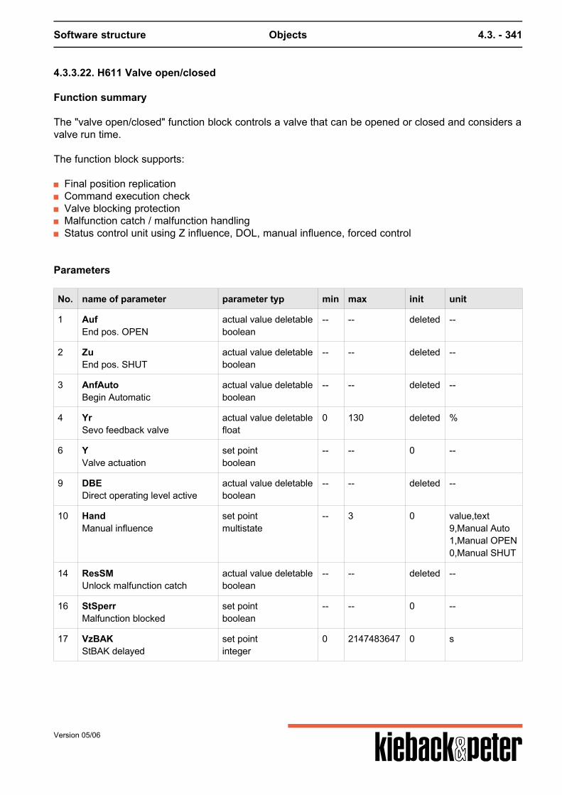
Software structure Objects 4.3. - 341
4.3.3.22. H611 Valve open/closed
Function summary
The "valve open/closed" function block controls a valve that can be opened or closed and considers avalve run time.
The function block supports:
Final position replication Command execution check Valve blocking protection Malfunction catch / malfunction handling Status control unit using Z influence, DOL, manual influence, forced control
Parameters
No. name of parameter parameter typ min max init unit
1 AufEnd pos. OPEN
actual value deletableboolean
-- -- deleted --
2 ZuEnd pos. SHUT
actual value deletableboolean
-- -- deleted --
3 AnfAutoBegin Automatic
actual value deletableboolean
-- -- deleted --
4 YrSevo feedback valve
actual value deletablefloat
0 130 deleted %
6 YValve actuation
set pointboolean
-- -- 0 --
9 DBEDirect operating level active
actual value deletableboolean
-- -- deleted --
10 HandManual influence
set pointmultistate
-- 3 0 value,text9,Manual Auto1,Manual OPEN0,Manual SHUT
14 ResSMUnlock malfunction catch
actual value deletableboolean
-- -- deleted --
16 StSperrMalfunction blocked
set pointboolean
-- -- 0 --
17 VzBAKStBAK delayed
set pointinteger
0 2147483647 0 s
Version 05/06
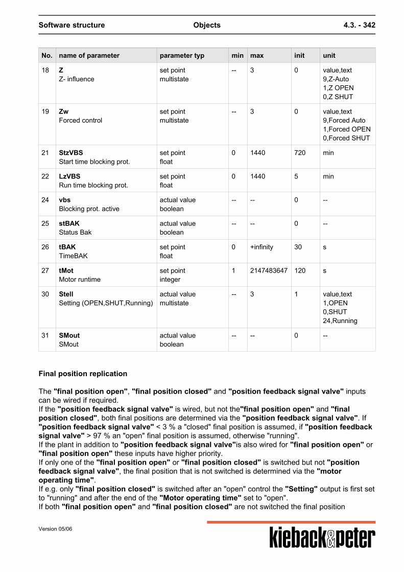
Software structure Objects 4.3. - 342
No. name of parameter parameter typ min max init unit
18 ZZ- influence
set pointmultistate
-- 3 0 value,text9,Z-Auto1,Z OPEN0,Z SHUT
19 ZwForced control
set pointmultistate
-- 3 0 value,text9,Forced Auto1,Forced OPEN0,Forced SHUT
21 StzVBSStart time blocking prot.
set pointfloat
0 1440 720 min
22 LzVBSRun time blocking prot.
set pointfloat
0 1440 5 min
24 vbsBlocking prot. active
actual valueboolean
-- -- 0 --
25 stBAKStatus Bak
actual valueboolean
-- -- 0 --
26 tBAKTimeBAK
set pointfloat
0 +infinity 30 s
27 tMotMotor runtime
set pointinteger
1 2147483647 120 s
30 StellSetting (OPEN,SHUT,Running)
actual valuemultistate
-- 3 1 value,text1,OPEN0,SHUT24,Running
31 SMoutSMout
actual valueboolean
-- -- 0 --
Final position replication
The "final position open", "final position closed" and "position feedback signal valve" inputscan be wired if required.If the "position feedback signal valve" is wired, but not the"final position open" and "finalposition closed", both final positions are determined via the "position feedback signal valve". If"position feedback signal valve" < 3 % a "closed" final position is assumed, if "position feedbacksignal valve" > 97 % an "open" final position is assumed, otherwise "running".If the plant in addition to "position feedback signal valve"is also wired for "final position open" or"final position open" these inputs have higher priority.If only one of the "final position open" or "final position closed" is switched but not "positionfeedback signal valve", the final position that is not switched is determined via the "motoroperating time".If e.g. only "final position closed" is switched after an "open" control the "Setting" output is first setto "running" and after the end of the "Motor operating time" set to "open".If both "final position open" and "final position closed" are not switched the final position
Version 05/06
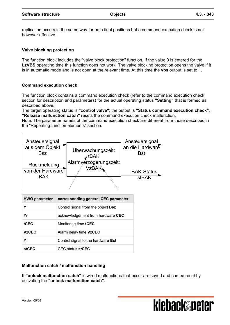
Software structure Objects 4.3. - 343
replication occurs in the same way for both final positions but a command execution check is nothowever effective.
Valve blocking protection
The function block includes the "valve block protection" function. If the value 0 is entered for theLzVBS operating time this function does not work. The valve blocking protection opens the valve if itis in automatic mode and is not open at the relevant time. At this time the vbs output is set to 1.
Command execution check
The function block contains a command execution check (refer to the command execution checksection for description and parameters) for the actual operating status "Setting" that is formed asdescribed above.The target operating status is "control valve"; the output is "Status command execution check"."Release malfunction catch" resets the command execution check malfunction.Note: The parameter names of the command execution check are different from those described inthe "Repeating function elements" section.
HWO parameter corresponding general CEC parameter
Y Control signal from the object Bsz
Yr acknowledgement from hardware CEC
tCEC Monitoring time tCEC
VzCEC Alarm delay time VzCEC
Y Control signal to the hardware Bst
stCEC CEC status stCEC
Malfunction catch / malfunction handling
If "unlock malfunction catch" is wired malfunctions that occur are saved and can be reset byactivating the "unlock malfunction catch".
Version 05/06
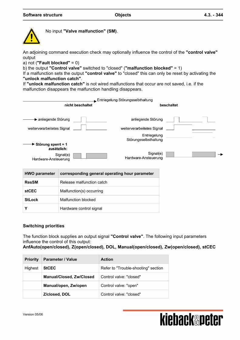
Software structure Objects 4.3. - 344
No input "Valve malfunction" (SM).
An adjoining command execution check may optionally influence the control of the "control valve"outputa) not ("Fault blocked" = 0)b) the output "Control valve" switched to "closed" ("malfunction blocked" = 1)If a malfunction sets the output "control valve" to "closed" this can only be reset by activating the"unlock malfunction catch".If "unlock malfunction catch" is not wired malfunctions that occur are not saved, i.e. if themalfunction disappears the malfunction handling disappears.
HWO parameter corresponding general operating hour parameter
ResSM Release malfunction catch
stCEC Malfunction(s) occurring
StLock Malfunction blocked
Y Hardware control signal
Switching priorities
The function block supplies an output signal "Control valve". The following input parametersinfluence the control of this output:AnfAuto(open/closed), Z(open/closed), DOL, Manual(open/closed), Zw(open/closed), stCEC
Priority Parameter / Value Action
Highest StCEC Refer to "Trouble-shooting" section
Manual/Closed, Zw/Closed Control valve: "closed"
Manual/open, Zw/open Control valve: "open"
Z/closed, DOL Control valve: "closed"
Version 05/06

Software structure Objects 4.3. - 345
Priority Parameter / Value Action
Z/open Control valve: "open"
lowest Auto Automatic operation
"Status command execution check ..." malfunctions that occur are not reset by "non-automatic"operation.
Version 05/06
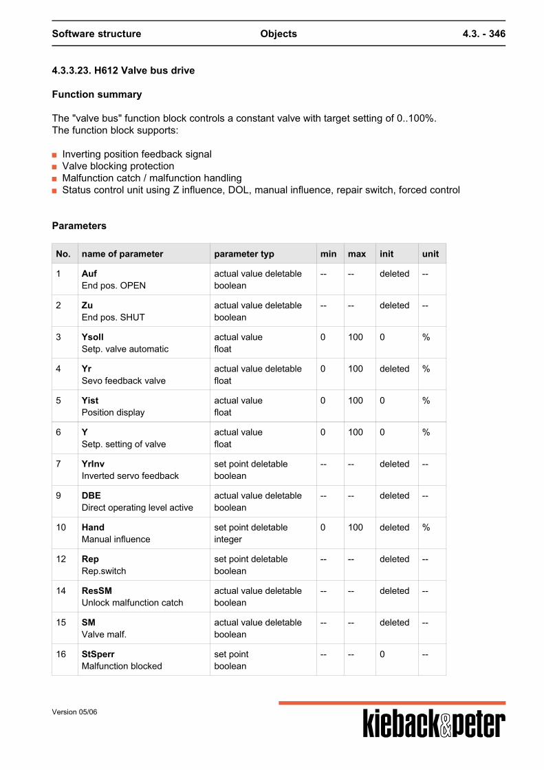
Software structure Objects 4.3. - 346
4.3.3.23. H612 Valve bus drive
Function summary
The "valve bus" function block controls a constant valve with target setting of 0..100%.The function block supports:
Inverting position feedback signal Valve blocking protection Malfunction catch / malfunction handling Status control unit using Z influence, DOL, manual influence, repair switch, forced control
Parameters
No. name of parameter parameter typ min max init unit
1 AufEnd pos. OPEN
actual value deletableboolean
-- -- deleted --
2 ZuEnd pos. SHUT
actual value deletableboolean
-- -- deleted --
3 YsollSetp. valve automatic
actual valuefloat
0 100 0 %
4 YrSevo feedback valve
actual value deletablefloat
0 100 deleted %
5 YistPosition display
actual valuefloat
0 100 0 %
6 YSetp. setting of valve
actual valuefloat
0 100 0 %
7 YrInvInverted servo feedback
set point deletableboolean
-- -- deleted --
9 DBEDirect operating level active
actual value deletableboolean
-- -- deleted --
10 HandManual influence
set point deletableinteger
0 100 deleted %
12 RepRep.switch
set point deletableboolean
-- -- deleted --
14 ResSMUnlock malfunction catch
actual value deletableboolean
-- -- deleted --
15 SMValve malf.
actual value deletableboolean
-- -- deleted --
16 StSperrMalfunction blocked
set pointboolean
-- -- 0 --
Version 05/06
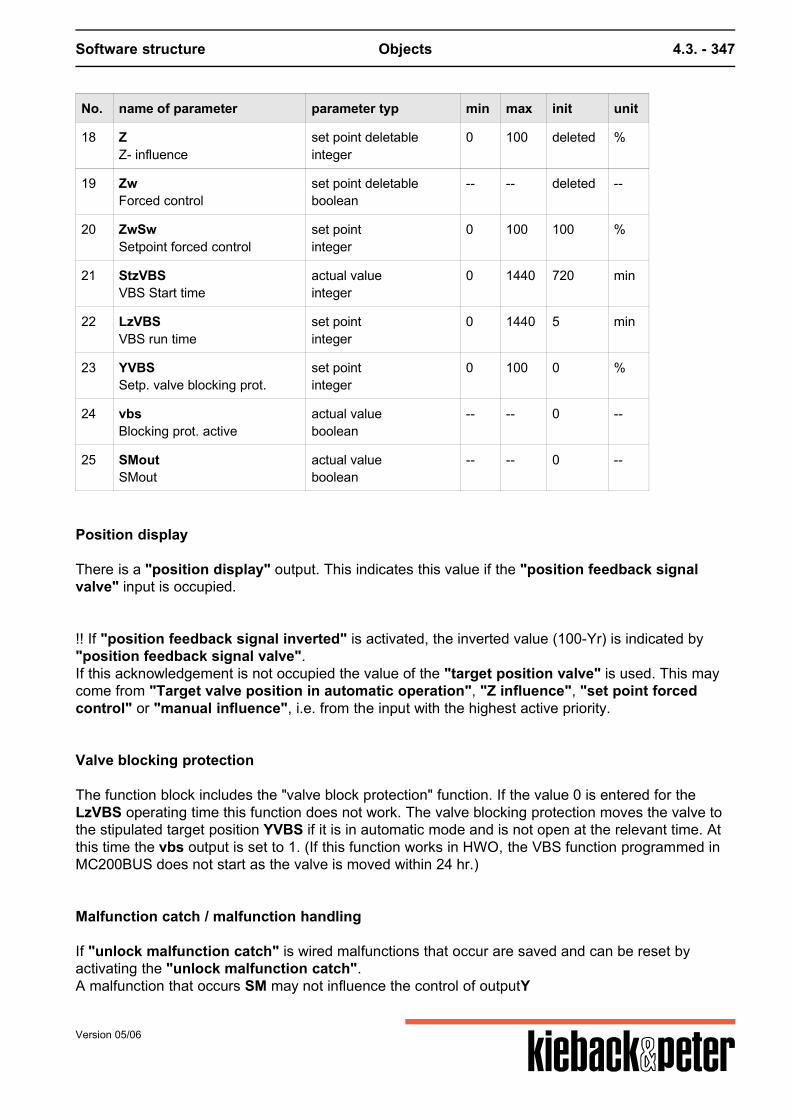
Software structure Objects 4.3. - 347
No. name of parameter parameter typ min max init unit
18 ZZ- influence
set point deletableinteger
0 100 deleted %
19 ZwForced control
set point deletableboolean
-- -- deleted --
20 ZwSwSetpoint forced control
set pointinteger
0 100 100 %
21 StzVBSVBS Start time
actual valueinteger
0 1440 720 min
22 LzVBSVBS run time
set pointinteger
0 1440 5 min
23 YVBSSetp. valve blocking prot.
set pointinteger
0 100 0 %
24 vbsBlocking prot. active
actual valueboolean
-- -- 0 --
25 SMoutSMout
actual valueboolean
-- -- 0 --
Position display
There is a "position display" output. This indicates this value if the "position feedback signalvalve" input is occupied. !! If "position feedback signal inverted" is activated, the inverted value (100-Yr) is indicated by"position feedback signal valve".If this acknowledgement is not occupied the value of the "target position valve" is used. This maycome from "Target valve position in automatic operation", "Z influence", "set point forcedcontrol" or "manual influence", i.e. from the input with the highest active priority.
Valve blocking protection
The function block includes the "valve block protection" function. If the value 0 is entered for theLzVBS operating time this function does not work. The valve blocking protection moves the valve tothe stipulated target position YVBS if it is in automatic mode and is not open at the relevant time. Atthis time the vbs output is set to 1. (If this function works in HWO, the VBS function programmed inMC200BUS does not start as the valve is moved within 24 hr.)
Malfunction catch / malfunction handling
If "unlock malfunction catch" is wired malfunctions that occur are saved and can be reset byactivating the "unlock malfunction catch".A malfunction that occurs SM may not influence the control of outputY
Version 05/06
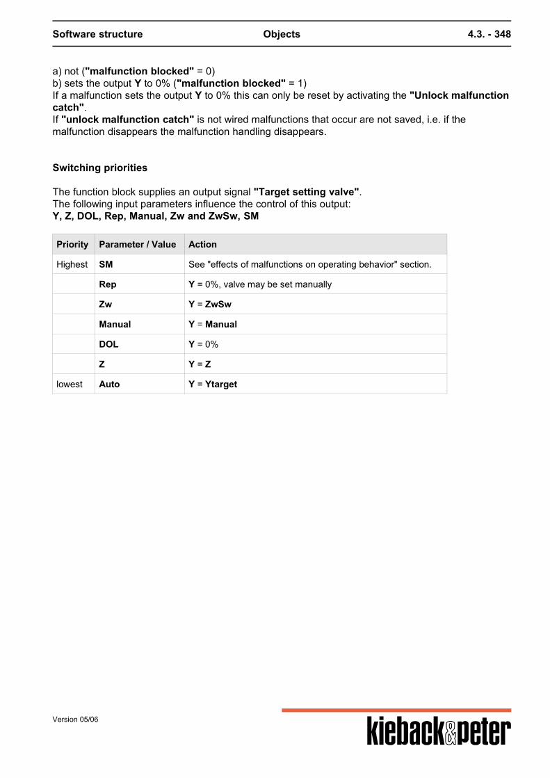
Software structure Objects 4.3. - 348
a) not ("malfunction blocked" = 0)b) sets the output Y to 0% ("malfunction blocked" = 1)If a malfunction sets the output Y to 0% this can only be reset by activating the "Unlock malfunctioncatch".If "unlock malfunction catch" is not wired malfunctions that occur are not saved, i.e. if themalfunction disappears the malfunction handling disappears.
Switching priorities
The function block supplies an output signal "Target setting valve".The following input parameters influence the control of this output:Y, Z, DOL, Rep, Manual, Zw and ZwSw, SM
Priority Parameter / Value Action
Highest SM See "effects of malfunctions on operating behavior" section.
Rep Y = 0%, valve may be set manually
Zw Y = ZwSw
Manual Y = Manual
DOL Y = 0%
Z Y = Z
lowest Auto Y = Ytarget
Version 05/06
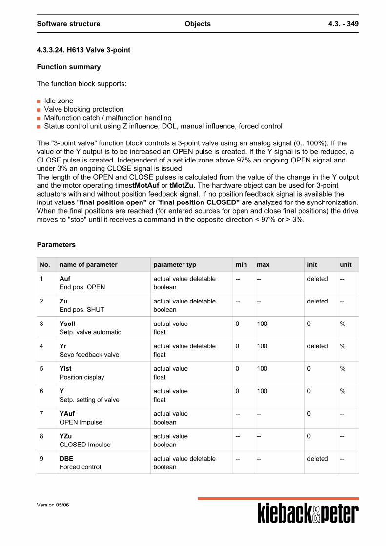
Software structure Objects 4.3. - 349
4.3.3.24. H613 Valve 3-point
Function summary
The function block supports:
Idle zone Valve blocking protection Malfunction catch / malfunction handling Status control unit using Z influence, DOL, manual influence, forced control
The "3-point valve" function block controls a 3-point valve using an analog signal (0...100%). If thevalue of the Y output is to be increased an OPEN pulse is created. If the Y signal is to be reduced, aCLOSE pulse is created. Independent of a set idle zone above 97% an ongoing OPEN signal andunder 3% an ongoing CLOSE signal is issued.The length of the OPEN and CLOSE pulses is calculated from the value of the change in the Y outputand the motor operating timestMotAuf or tMotZu. The hardware object can be used for 3-pointactuators with and without position feedback signal. If no position feedback signal is available theinput values "final position open" or "final position CLOSED" are analyzed for the synchronization.When the final positions are reached (for entered sources for open and close final positions) the drivemoves to "stop" until it receives a command in the opposite direction < 97% or > 3%.
Parameters
No. name of parameter parameter typ min max init unit
1 AufEnd pos. OPEN
actual value deletableboolean
-- -- deleted --
2 ZuEnd pos. SHUT
actual value deletableboolean
-- -- deleted --
3 YsollSetp. valve automatic
actual valuefloat
0 100 0 %
4 YrSevo feedback valve
actual value deletablefloat
0 100 deleted %
5 YistPosition display
actual valuefloat
0 100 0 %
6 YSetp. setting of valve
actual valuefloat
0 100 0 %
7 YAufOPEN Impulse
actual valueboolean
-- -- 0 --
8 YZuCLOSED Impulse
actual valueboolean
-- -- 0 --
9 DBEForced control
actual value deletableboolean
-- -- deleted --
Version 05/06
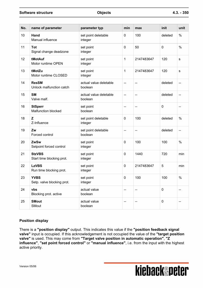
Software structure Objects 4.3. - 350
No. name of parameter parameter typ min max init unit
10 HandManual influence
set point deletableinteger
0 100 deleted %
11 TotSignal change deadzone
set pointinteger
0 50 0 %
12 tMotAufMotor runtime OPEN
set pointinteger
1 2147483647 120 s
13 tMotZuMotor runtime CLOSED
set pointinteger
1 2147483647 120 s
14 ResSMUnlock malfunction catch
actual value deletableboolean
-- -- deleted --
15 SMValve malf.
actual value deletableboolean
-- -- deleted --
16 StSperrMalfunction blocked
set pointboolean
-- -- 0 --
18 ZZ-Influence
set point deletableinteger
0 100 deleted %
19 ZwForced control
set point deletableboolean
-- -- deleted --
20 ZwSwSetpoint forced control
set pointinteger
0 100 100 %
21 StzVBSStart time blocking prot.
set pointinteger
0 1440 720 min
22 LzVBSRun time blocking prot.
set pointinteger
0 2147483647 5 min
23 YVBSSetp. valve blocking prot.
set pointinteger
0 100 100 %
24 vbsBlocking prot. active
actual valueboolean
-- -- 0 --
25 SMoutSMout
actual valueboolean
-- -- 0 --
Position display
There is a "position display" output. This indicates this value if the "position feedback signalvalve" input is occupied. If this acknowledgement is not occupied the value of the "target positionvalve" is used. This may come from "Target valve position in automatic operation", "Zinfluence", "set point forced control" or "manual influence", i.e. from the input with the highestactive priority.
Version 05/06
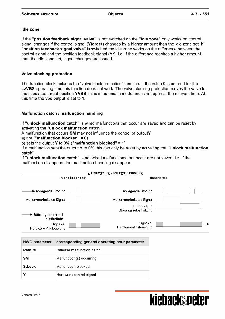
Software structure Objects 4.3. - 351
Idle zone
If the "position feedback signal valve" is not switched on the "idle zone" only works on controlsignal changes if the control signal (Ytarget) changes by a higher amount than the idle zone set. If"position feedback signal valve" is switched the idle zone works on the difference between thecontrol signal and the position feedback signal (Yr). I.e. if the difference reaches a higher amountthan the idle zone set, signal changes are issued.
Valve blocking protection
The function block includes the "valve block protection" function. If the value 0 is entered for theLzVBS operating time this function does not work. The valve blocking protection moves the valve tothe stipulated target position YVBS if it is in automatic mode and is not open at the relevant time. Atthis time the vbs output is set to 1.
Malfunction catch / malfunction handling
If "unlock malfunction catch" is wired malfunctions that occur are saved and can be reset byactivating the "unlock malfunction catch".A malfunction that occurs SM may not influence the control of outputYa) not ("malfunction blocked" = 0)b) sets the output Y to 0% ("malfunction blocked" = 1)If a malfunction sets the output Y to 0% this can only be reset by activating the "Unlock malfunctioncatch".If "unlock malfunction catch" is not wired malfunctions that occur are not saved, i.e. if themalfunction disappears the malfunction handling disappears.
HWO parameter corresponding general operating hour parameter
ResSM Release malfunction catch
SM Malfunction(s) occurring
StLock Malfunction blocked
Y Hardware control signal
Version 05/06
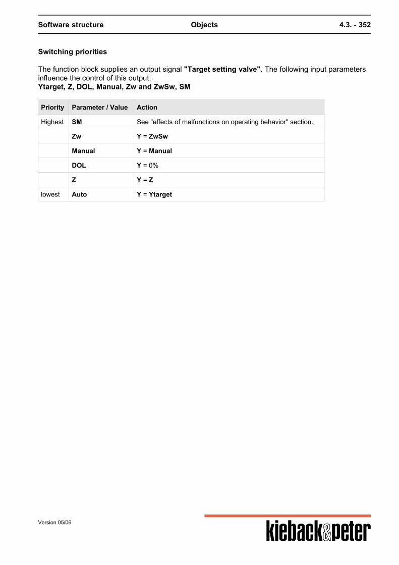
Software structure Objects 4.3. - 352
Switching priorities
The function block supplies an output signal "Target setting valve". The following input parametersinfluence the control of this output:Ytarget, Z, DOL, Manual, Zw and ZwSw, SM
Priority Parameter / Value Action
Highest SM See "effects of malfunctions on operating behavior" section.
Zw Y = ZwSw
Manual Y = Manual
DOL Y = 0%
Z Y = Z
lowest Auto Y = Ytarget
Version 05/06
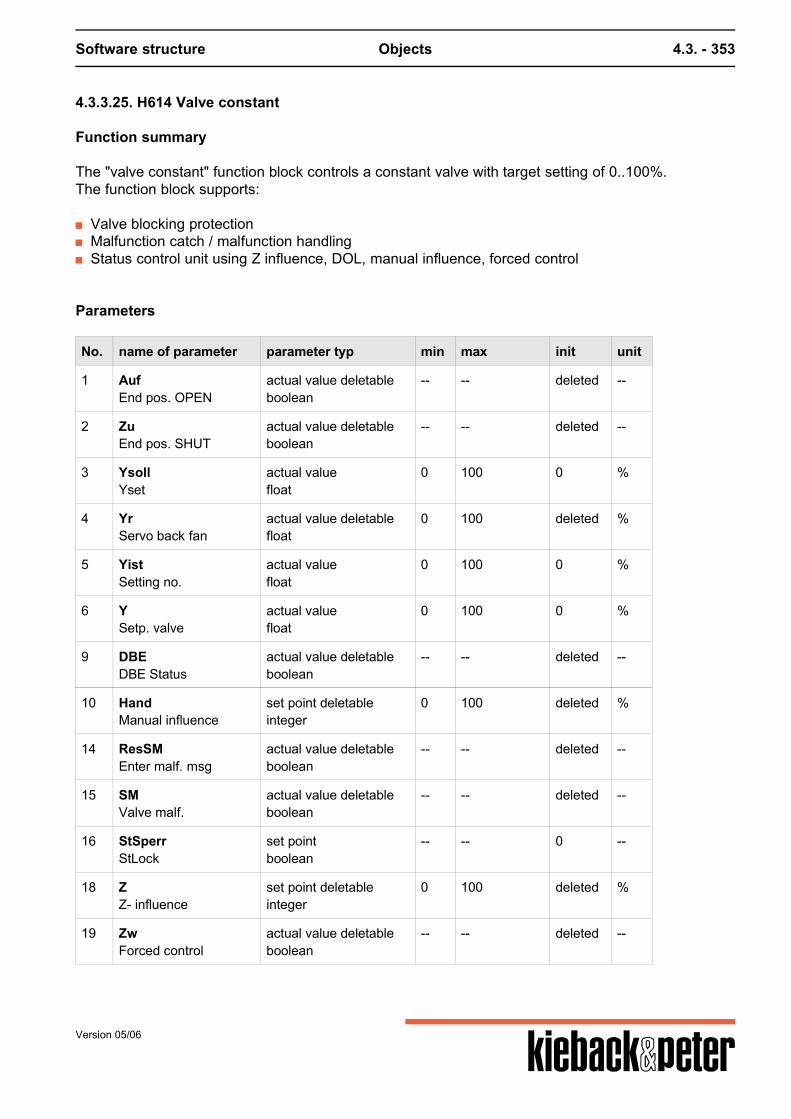
Software structure Objects 4.3. - 353
4.3.3.25. H614 Valve constant
Function summary
The "valve constant" function block controls a constant valve with target setting of 0..100%.The function block supports:
Valve blocking protection Malfunction catch / malfunction handling Status control unit using Z influence, DOL, manual influence, forced control
Parameters
No. name of parameter parameter typ min max init unit
1 AufEnd pos. OPEN
actual value deletableboolean
-- -- deleted --
2 ZuEnd pos. SHUT
actual value deletableboolean
-- -- deleted --
3 YsollYset
actual valuefloat
0 100 0 %
4 YrServo back fan
actual value deletablefloat
0 100 deleted %
5 YistSetting no.
actual valuefloat
0 100 0 %
6 YSetp. valve
actual valuefloat
0 100 0 %
9 DBEDBE Status
actual value deletableboolean
-- -- deleted --
10 HandManual influence
set point deletableinteger
0 100 deleted %
14 ResSMEnter malf. msg
actual value deletableboolean
-- -- deleted --
15 SMValve malf.
actual value deletableboolean
-- -- deleted --
16 StSperrStLock
set pointboolean
-- -- 0 --
18 ZZ- influence
set point deletableinteger
0 100 deleted %
19 ZwForced control
actual value deletableboolean
-- -- deleted --
Version 05/06
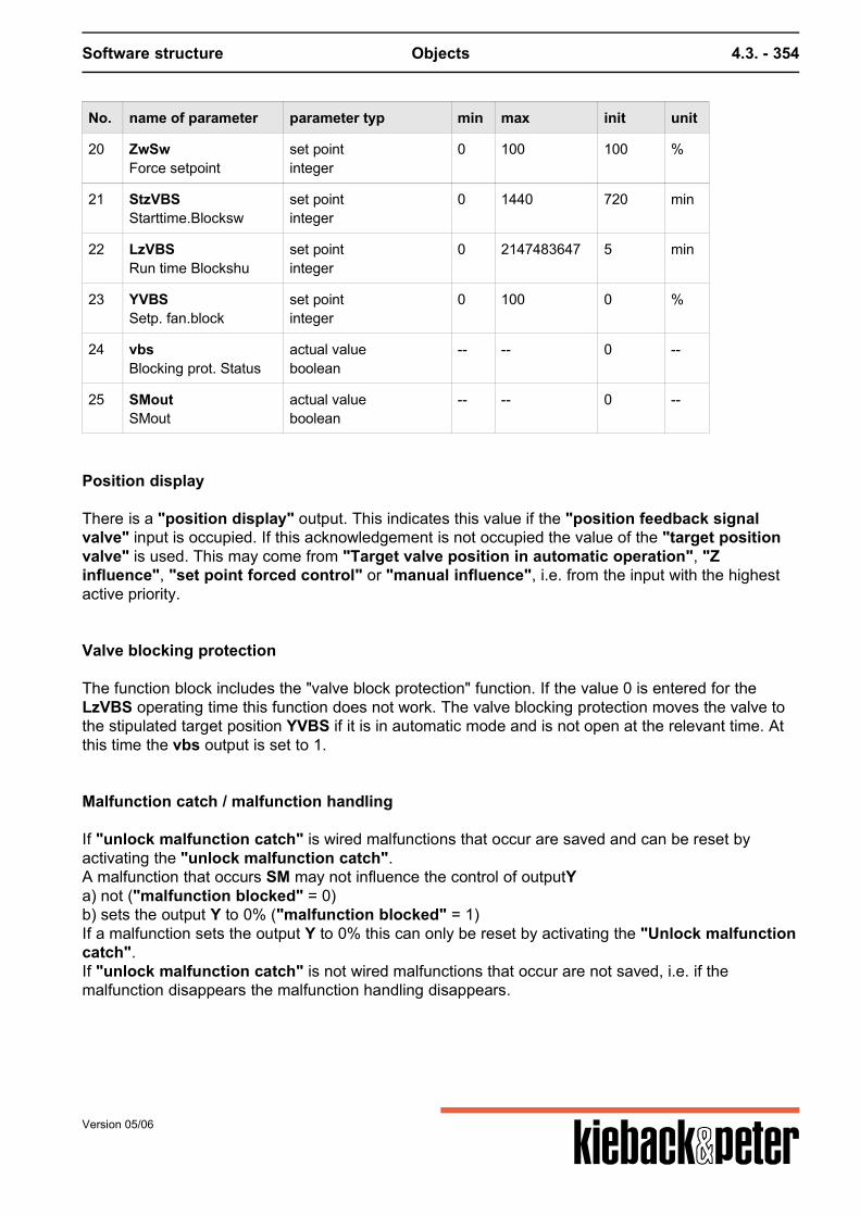
Software structure Objects 4.3. - 354
No. name of parameter parameter typ min max init unit
20 ZwSwForce setpoint
set pointinteger
0 100 100 %
21 StzVBSStarttime.Blocksw
set pointinteger
0 1440 720 min
22 LzVBSRun time Blockshu
set pointinteger
0 2147483647 5 min
23 YVBSSetp. fan.block
set pointinteger
0 100 0 %
24 vbsBlocking prot. Status
actual valueboolean
-- -- 0 --
25 SMoutSMout
actual valueboolean
-- -- 0 --
Position display
There is a "position display" output. This indicates this value if the "position feedback signalvalve" input is occupied. If this acknowledgement is not occupied the value of the "target positionvalve" is used. This may come from "Target valve position in automatic operation", "Zinfluence", "set point forced control" or "manual influence", i.e. from the input with the highestactive priority.
Valve blocking protection
The function block includes the "valve block protection" function. If the value 0 is entered for theLzVBS operating time this function does not work. The valve blocking protection moves the valve tothe stipulated target position YVBS if it is in automatic mode and is not open at the relevant time. Atthis time the vbs output is set to 1.
Malfunction catch / malfunction handling
If "unlock malfunction catch" is wired malfunctions that occur are saved and can be reset byactivating the "unlock malfunction catch".A malfunction that occurs SM may not influence the control of outputYa) not ("malfunction blocked" = 0)b) sets the output Y to 0% ("malfunction blocked" = 1)If a malfunction sets the output Y to 0% this can only be reset by activating the "Unlock malfunctioncatch".If "unlock malfunction catch" is not wired malfunctions that occur are not saved, i.e. if themalfunction disappears the malfunction handling disappears.
Version 05/06
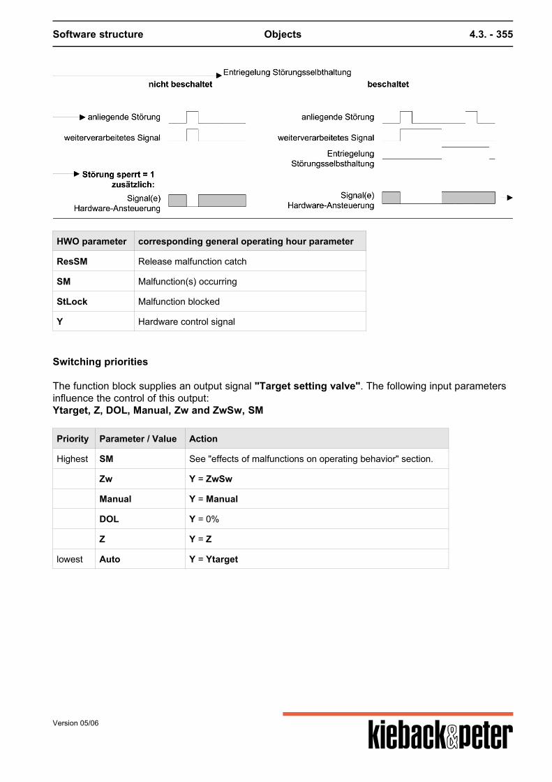
Software structure Objects 4.3. - 355
HWO parameter corresponding general operating hour parameter
ResSM Release malfunction catch
SM Malfunction(s) occurring
StLock Malfunction blocked
Y Hardware control signal
Switching priorities
The function block supplies an output signal "Target setting valve". The following input parametersinfluence the control of this output:Ytarget, Z, DOL, Manual, Zw and ZwSw, SM
Priority Parameter / Value Action
Highest SM See "effects of malfunctions on operating behavior" section.
Zw Y = ZwSw
Manual Y = Manual
DOL Y = 0%
Z Y = Z
lowest Auto Y = Ytarget
Version 05/06

Software structure Objects 4.3. - 356
4.3.3.26. H701 Burner single stage
Function summary
The "burner single stage" function block controls a single-stage burner and supports:pump and cover control during the warm-up phase / request for controlChimney sweep functionOperating hours / limiting valueSwitching delaysCommand execution checkMalfunction catch / malfunction handlingStatus control unit using Z influence, DOL, manual influence, repair switch, forced control
Parameters
No. name of parameter parameter typ min max init unit
1 AnfAutoBegin Automatic
actual value deletableboolean
-- -- deleted --
2 AnfBrEinBegin Burner ON
actual value deletableboolean
-- -- deleted --
3 AnfPKBegin Pump / Flap
actual valueboolean
-- -- 0 --
4 AnlVerzStart delay Automatic
set pointinteger
0 2147483647 0 s
5 BMBron burner message
actual value deletableboolean
-- -- deleted --
6 BMPuKlon pump/flap message
actual value deletableboolean
-- -- deleted --
7 BhOperating hours
set pointinteger
0 2147483647 0 h
8 BhAktivOper.hrs. of activation
set pointboolean
-- -- 0 --
9 BhGwOper.hrs. limit value
set pointinteger
0 2147483647 0 h
10 BrEinBurner ON
actual valueboolean
-- -- 0 --
11 DBEDirect operating level active
actual value deletableboolean
-- -- deleted --
12 HandManual switch
set pointmultistate
-- 3 0 value,text9,Auto0,OFF1,ON
Version 05/06

Software structure Objects 4.3. - 357
No. name of parameter parameter typ min max init unit
13 RepRepare switch
actual value deletableboolean
-- -- deleted --
14 ResBhReset opr. hours
actual value deletableboolean
-- -- deleted --
15 ResSMrelease malf. self-holding
actual value deletableboolean
-- -- deleted --
16 SFChimneysweep function
set point deletableboolean
-- -- deleted --
17 SFZeitContinuous chimneysweep function
set pointinteger
0 300 30 min
18 SFaktivChimneysweep function is active
actual valueboolean
-- -- 0 --
19 SMBurner malfunction
actual value deletableboolean
-- -- deleted --
20 StSperrMalfunction blocked
set pointboolean
-- -- 0 --
21 VzBAKstBAK delayed
actual valueinteger
0 2147483647 0 s
22 ZZ- influence
set pointmultistate
-- 3 0 value,text9,Auto0,OFF1,ON
23 ZwForced control
set pointmultistate
-- 3 0 value,text9,Auto0,OFF1,ON
24 gBhLimit value error by opr.hrs.
actual valueboolean
-- -- 0 --
25 regBegin Control
actual valueboolean
-- -- 0 --
26 stBAKStatus BAK Burner
actual valueboolean
-- -- 0 --
27 tBAKTime BAK
set pointinteger
0 2147483647 30 s
28 SMoutSMout
actual valueboolean
-- -- 0 --
Version 05/06
Software structure Objects 4.3. - 358
pump and cover control during the warm-up phase / request for control
If the burner is to be switched on the "pump/cover request" is first set to 1.Then there is a pause for the "operational message pump/cover" = 1 if this input is wired.At the same time as "request pump/cover" the "request control" is set to 1. This signals thesubsequent control beyond the hardware object that the burner is standing by to produce heat. If thenthe signal "request burner on" is set to 1 by the control and "operational message pump / cover"=1, the burner is switched on ("burner on"=1).For "operational message pump/cover" this does not include a command execution check as"request pump / cover" should always be linked to a "pump" or "cover" hardware object thatcontains its own command execution check.
Chimney sweep function
The chimney sweep function switches the burner on for the"chimney sweep function time span" ifthe burner is in automatic mode and is not already switched on.If the burner is in automatic mode and already switched on the plant ensures that the burner stays onfor the "chimney sweep function time span", even if the "request automatic operation" is set to0 in this time.When the chimney sweep function is activated the "chimney sweep function active" parameter isset to 1.
Operating hours / limiting value
The operating hours of the burner can be counted, the operating hours counter can be preset andoccupied by a limiting value. If the limiting value is exceeded a message is produced. If the input forthe burner operating message is not switched the control output "burner on" is used for counting.Note: The parameter names of the operating hour counter are different from those described in the"Repeating function elements" section.
Version 05/06
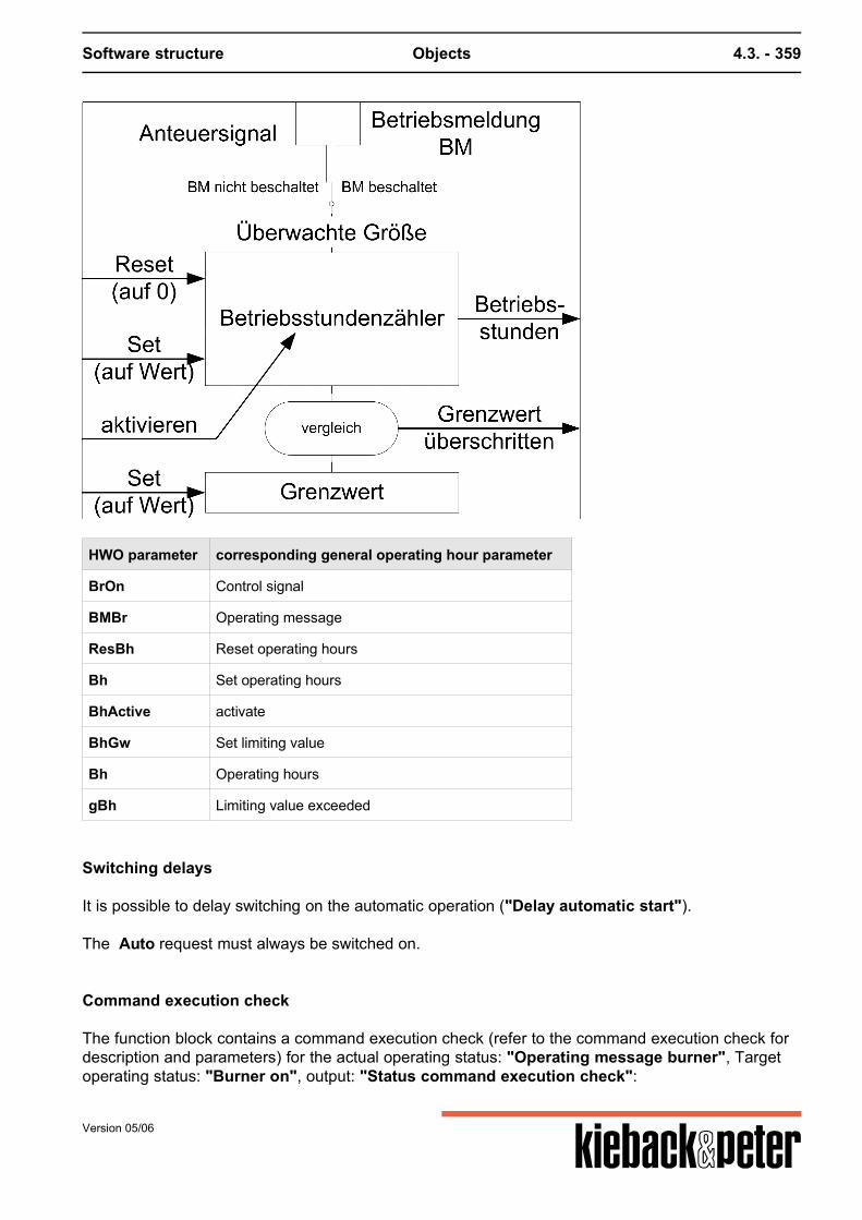
Software structure Objects 4.3. - 359
HWO parameter corresponding general operating hour parameter
BrOn Control signal
BMBr Operating message
ResBh Reset operating hours
Bh Set operating hours
BhActive activate
BhGw Set limiting value
Bh Operating hours
gBh Limiting value exceeded
Switching delays
It is possible to delay switching on the automatic operation ("Delay automatic start"). The Auto request must always be switched on.
Command execution check
The function block contains a command execution check (refer to the command execution check fordescription and parameters) for the actual operating status: "Operating message burner", Targetoperating status: "Burner on", output: "Status command execution check":
Version 05/06
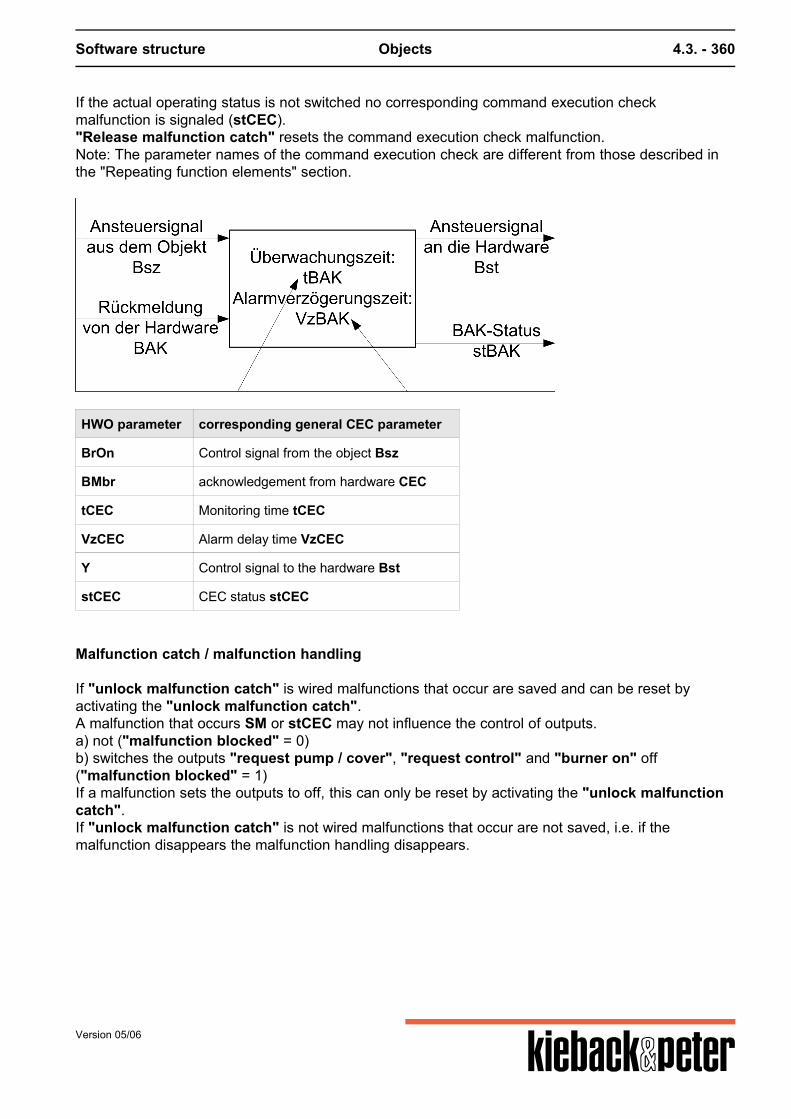
Software structure Objects 4.3. - 360
If the actual operating status is not switched no corresponding command execution checkmalfunction is signaled (stCEC)."Release malfunction catch" resets the command execution check malfunction.Note: The parameter names of the command execution check are different from those described inthe "Repeating function elements" section.
HWO parameter corresponding general CEC parameter
BrOn Control signal from the object Bsz
BMbr acknowledgement from hardware CEC
tCEC Monitoring time tCEC
VzCEC Alarm delay time VzCEC
Y Control signal to the hardware Bst
stCEC CEC status stCEC
Malfunction catch / malfunction handling
If "unlock malfunction catch" is wired malfunctions that occur are saved and can be reset byactivating the "unlock malfunction catch".A malfunction that occurs SM or stCEC may not influence the control of outputs.a) not ("malfunction blocked" = 0)b) switches the outputs "request pump / cover", "request control" and "burner on" off("malfunction blocked" = 1)If a malfunction sets the outputs to off, this can only be reset by activating the "unlock malfunctioncatch".If "unlock malfunction catch" is not wired malfunctions that occur are not saved, i.e. if themalfunction disappears the malfunction handling disappears.
Version 05/06
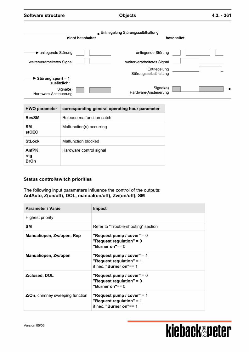
Software structure Objects 4.3. - 361
HWO parameter corresponding general operating hour parameter
ResSM Release malfunction catch
SMstCEC
Malfunction(s) occurring
StLock Malfunction blocked
AnfPKregBrOn
Hardware control signal
Status control/switch priorities
The following input parameters influence the control of the outputs:AnfAuto, Z(on/off), DOL, manual(on/off), Zw(on/off), SM
Parameter / Value Impact
Highest priority
SM Refer to "Trouble-shooting" section
Manual/open, Zw/open, Rep "Request pump / cover" = 0"Request regulation" = 0"Burner on"== 0
Manual/open, Zw/open "Request pump / cover" = 1"Request regulation" = 1if nec. "Burner on"== 1
Z/closed, DOL "Request pump / cover" = 0"Request regulation" = 0"Burner on"== 0
Z/On, chimney sweeping function "Request pump / cover" = 1"Request regulation" = 1if nec. "Burner on"== 1
Version 05/06
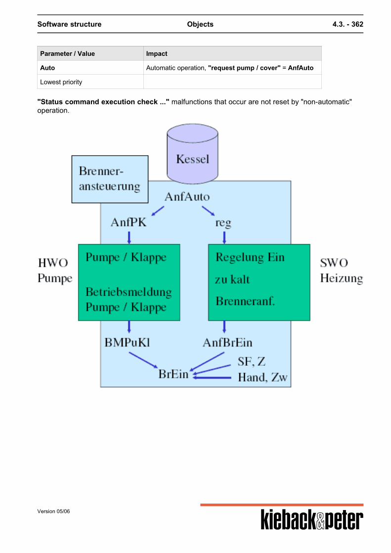
Software structure Objects 4.3. - 362
Parameter / Value Impact
Auto Automatic operation, "request pump / cover" = AnfAuto
Lowest priority
"Status command execution check ..." malfunctions that occur are not reset by "non-automatic"operation.
Version 05/06
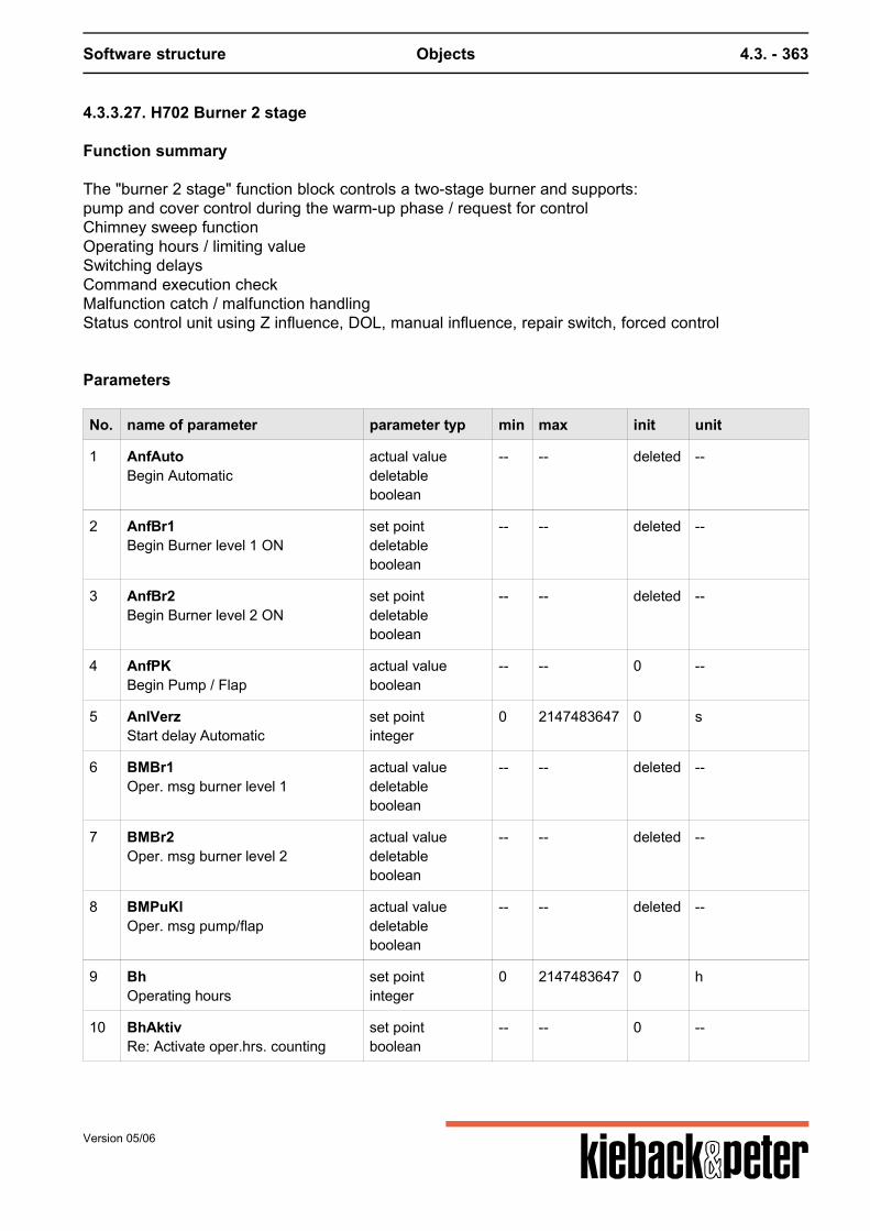
Software structure Objects 4.3. - 363
4.3.3.27. H702 Burner 2 stage
Function summary
The "burner 2 stage" function block controls a two-stage burner and supports:pump and cover control during the warm-up phase / request for controlChimney sweep functionOperating hours / limiting valueSwitching delaysCommand execution checkMalfunction catch / malfunction handlingStatus control unit using Z influence, DOL, manual influence, repair switch, forced control
Parameters
No. name of parameter parameter typ min max init unit
1 AnfAutoBegin Automatic
actual valuedeletableboolean
-- -- deleted --
2 AnfBr1Begin Burner level 1 ON
set pointdeletableboolean
-- -- deleted --
3 AnfBr2Begin Burner level 2 ON
set pointdeletableboolean
-- -- deleted --
4 AnfPKBegin Pump / Flap
actual valueboolean
-- -- 0 --
5 AnlVerzStart delay Automatic
set pointinteger
0 2147483647 0 s
6 BMBr1Oper. msg burner level 1
actual valuedeletableboolean
-- -- deleted --
7 BMBr2Oper. msg burner level 2
actual valuedeletableboolean
-- -- deleted --
8 BMPuKlOper. msg pump/flap
actual valuedeletableboolean
-- -- deleted --
9 BhOperating hours
set pointinteger
0 2147483647 0 h
10 BhAktivRe: Activate oper.hrs. counting
set pointboolean
-- -- 0 --
Version 05/06
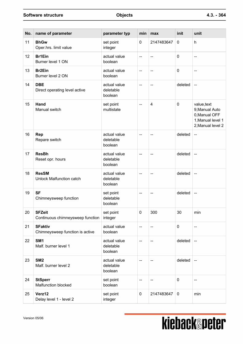
Software structure Objects 4.3. - 364
No. name of parameter parameter typ min max init unit
11 BhGwOper.hrs. limit value
set pointinteger
0 2147483647 0 h
12 Br1EinBurner level 1 ON
actual valueboolean
-- -- 0 --
13 Br2EinBurner level 2 ON
actual valueboolean
-- -- 0 --
14 DBEDirect operating level active
actual valuedeletableboolean
-- -- deleted --
15 HandManual switch
set pointmultistate
-- 4 0 value,text9,Manual Auto0,Manual OFF1,Manual level 12,Manual level 2
16 RepRepare switch
actual valuedeletableboolean
-- -- deleted --
17 ResBhReset opr. hours
actual valuedeletableboolean
-- -- deleted --
18 ResSMUnlock Malfunction catch
actual valuedeletableboolean
-- -- deleted --
19 SFChimneysweep function
set pointdeletableboolean
-- -- deleted --
20 SFZeitContinuous chimneysweep function
set pointinteger
0 300 30 min
21 SFaktivChimneysweep function is active
actual valueboolean
-- -- 0 --
22 SM1Malf. burner level 1
actual valuedeletableboolean
-- -- deleted --
23 SM2Malf. burner level 2
actual valuedeletableboolean
-- -- deleted --
24 StSperrMalfunction blocked
set pointboolean
-- -- 0 --
25 Verz12Delay level 1 - level 2
set pointinteger
0 2147483647 0 min
Version 05/06
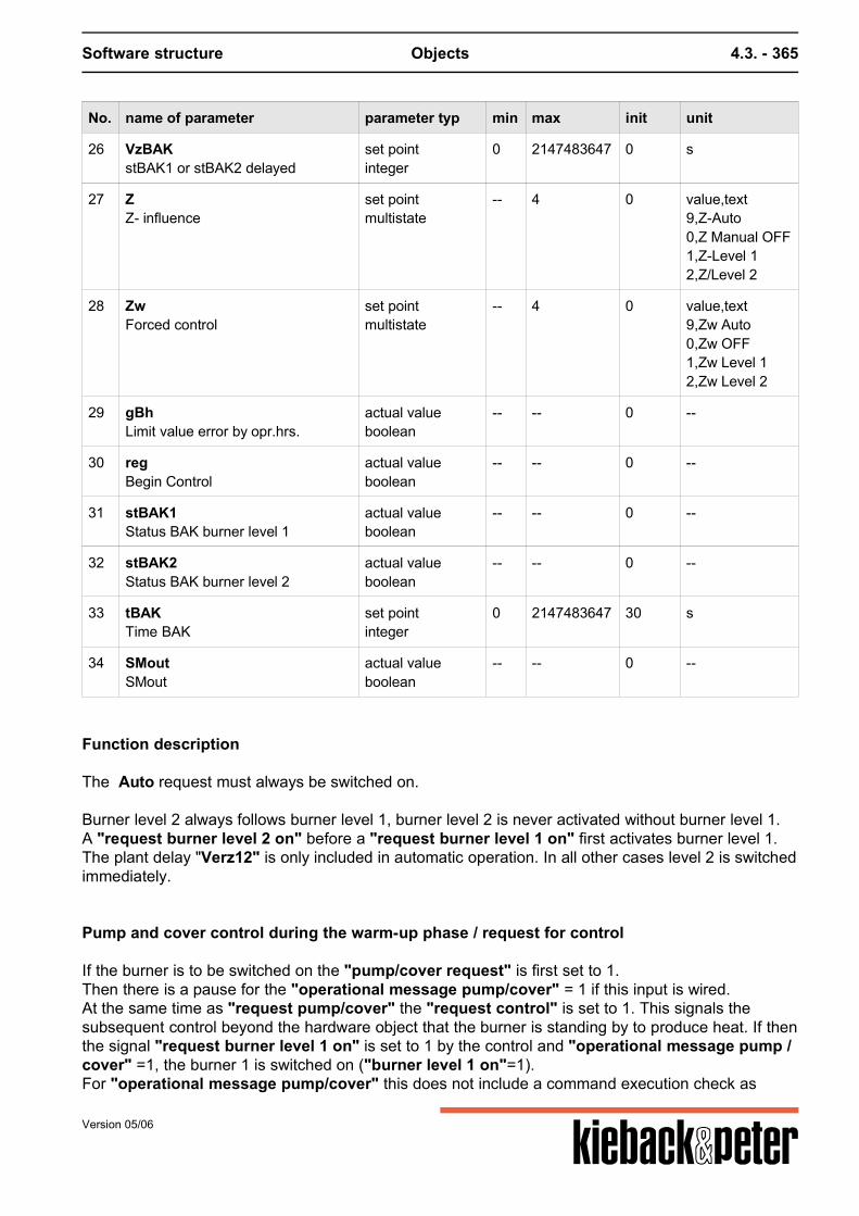
Software structure Objects 4.3. - 365
No. name of parameter parameter typ min max init unit
26 VzBAKstBAK1 or stBAK2 delayed
set pointinteger
0 2147483647 0 s
27 ZZ- influence
set pointmultistate
-- 4 0 value,text9,Z-Auto0,Z Manual OFF1,Z-Level 12,Z/Level 2
28 ZwForced control
set pointmultistate
-- 4 0 value,text9,Zw Auto0,Zw OFF1,Zw Level 12,Zw Level 2
29 gBhLimit value error by opr.hrs.
actual valueboolean
-- -- 0 --
30 regBegin Control
actual valueboolean
-- -- 0 --
31 stBAK1Status BAK burner level 1
actual valueboolean
-- -- 0 --
32 stBAK2Status BAK burner level 2
actual valueboolean
-- -- 0 --
33 tBAKTime BAK
set pointinteger
0 2147483647 30 s
34 SMoutSMout
actual valueboolean
-- -- 0 --
Function description
The Auto request must always be switched on. Burner level 2 always follows burner level 1, burner level 2 is never activated without burner level 1.A "request burner level 2 on" before a "request burner level 1 on" first activates burner level 1.The plant delay "Verz12" is only included in automatic operation. In all other cases level 2 is switchedimmediately.
Pump and cover control during the warm-up phase / request for control
If the burner is to be switched on the "pump/cover request" is first set to 1.Then there is a pause for the "operational message pump/cover" = 1 if this input is wired.At the same time as "request pump/cover" the "request control" is set to 1. This signals thesubsequent control beyond the hardware object that the burner is standing by to produce heat. If thenthe signal "request burner level 1 on" is set to 1 by the control and "operational message pump /cover" =1, the burner 1 is switched on ("burner level 1 on"=1).For "operational message pump/cover" this does not include a command execution check as
Version 05/06
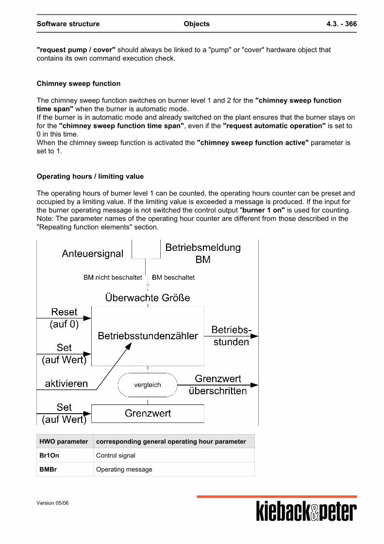
Software structure Objects 4.3. - 366
"request pump / cover" should always be linked to a "pump" or "cover" hardware object thatcontains its own command execution check.
Chimney sweep function
The chimney sweep function switches on burner level 1 and 2 for the "chimney sweep functiontime span" when the burner is automatic mode.If the burner is in automatic mode and already switched on the plant ensures that the burner stays onfor the "chimney sweep function time span", even if the "request automatic operation" is set to0 in this time.When the chimney sweep function is activated the "chimney sweep function active" parameter isset to 1.
Operating hours / limiting value
The operating hours of burner level 1 can be counted, the operating hours counter can be preset andoccupied by a limiting value. If the limiting value is exceeded a message is produced. If the input forthe burner operating message is not switched the control output "burner 1 on" is used for counting.Note: The parameter names of the operating hour counter are different from those described in the"Repeating function elements" section.
HWO parameter corresponding general operating hour parameter
Br1On Control signal
BMBr Operating message
Version 05/06
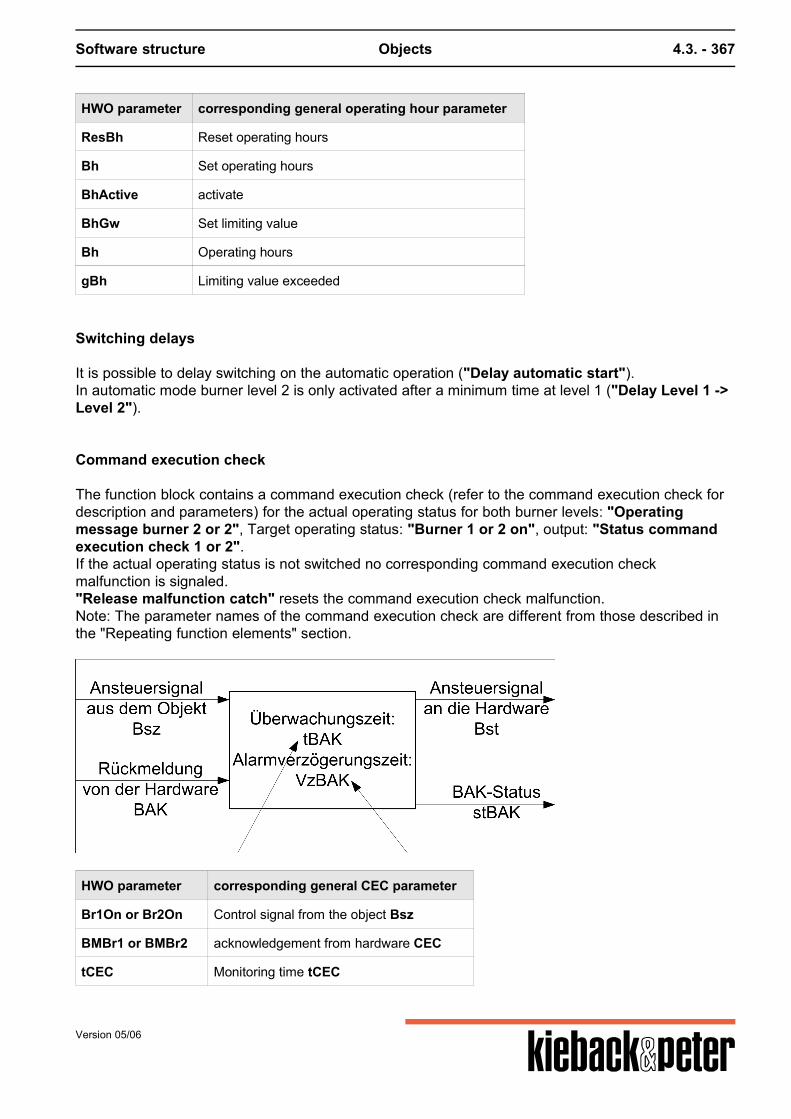
Software structure Objects 4.3. - 367
HWO parameter corresponding general operating hour parameter
ResBh Reset operating hours
Bh Set operating hours
BhActive activate
BhGw Set limiting value
Bh Operating hours
gBh Limiting value exceeded
Switching delays
It is possible to delay switching on the automatic operation ("Delay automatic start").In automatic mode burner level 2 is only activated after a minimum time at level 1 ("Delay Level 1 ->Level 2").
Command execution check
The function block contains a command execution check (refer to the command execution check fordescription and parameters) for the actual operating status for both burner levels: "Operatingmessage burner 2 or 2", Target operating status: "Burner 1 or 2 on", output: "Status commandexecution check 1 or 2".If the actual operating status is not switched no corresponding command execution checkmalfunction is signaled."Release malfunction catch" resets the command execution check malfunction.Note: The parameter names of the command execution check are different from those described inthe "Repeating function elements" section.
HWO parameter corresponding general CEC parameter
Br1On or Br2On Control signal from the object Bsz
BMBr1 or BMBr2 acknowledgement from hardware CEC
tCEC Monitoring time tCEC
Version 05/06
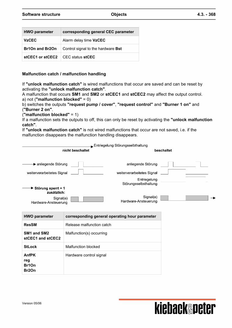
Software structure Objects 4.3. - 368
HWO parameter corresponding general CEC parameter
VzCEC Alarm delay time VzCEC
Br1On and Br2On Control signal to the hardware Bst
stCEC1 or stCEC2 CEC status stCEC
Malfunction catch / malfunction handling
If "unlock malfunction catch" is wired malfunctions that occur are saved and can be reset byactivating the "unlock malfunction catch".A malfunction that occurs SM1 and SM2 or stCEC1 and stCEC2 may affect the output control.a) not ("malfunction blocked" = 0)b) switches the outputs "request pump / cover", "request control" and "Burner 1 on" and("Burner 2 on".("malfunction blocked" = 1)If a malfunction sets the outputs to off, this can only be reset by activating the "unlock malfunctioncatch".If "unlock malfunction catch" is not wired malfunctions that occur are not saved, i.e. if themalfunction disappears the malfunction handling disappears.
HWO parameter corresponding general operating hour parameter
ResSM Release malfunction catch
SM1 and SM2stCEC1 and stCEC2
Malfunction(s) occurring
StLock Malfunction blocked
AnfPKregBr1OnBr2On
Hardware control signal
Version 05/06
Software structure Objects 4.3. - 369
Status control/switch priorities
The following input parameters influence the control of the outputs:AnfAuto, Z(Off/Level 1/Level 2), DOL, Manual(Off/Level 1/Level 2), Zw(Off/Level 1/Level 2), SM1and SM2
Parameter / Value Impact
Highest priority
SM1, SM2 Refer to "Trouble-shooting" section
Manual/open, Zw/open, Rep "Request pump / cover" = 0"Request regulation" = 0"Burner level 1 on"= 0"Burner level 2 on"= 0
Manual/Level 2, Zw/Level 2 "Request pump / cover" = 1"Request regulation" = 1If nec activate burner level 1 and level 2 (without Delay12)
Manual/Level 1, Zw/Level 1 "Request pump / cover" = 1"Request regulation" = 1if nec. activate burner level 1
Z/closed, DOL "Request pump / cover" = 0"Request regulation" = 0"Burner level 1 on"= 0"Burner level 2 on"= 0
Z/Level 2, chimney sweeping function "Request pump / cover" = 1"Request regulation" = 1Activate burner level 1 and level 2 (without Delay12)
Z/Level 1 "Request pump / cover" = 1"Request regulation" = 1if nec. activate burner level 1
Auto Automatic operation, "request pump / cover" = AnfAuto
Lowest priority
"Status command execution check ..." malfunctions that occur are not reset by "non-automatic"operation.
Version 05/06

Software structure Objects 4.3. - 370
Version 05/06
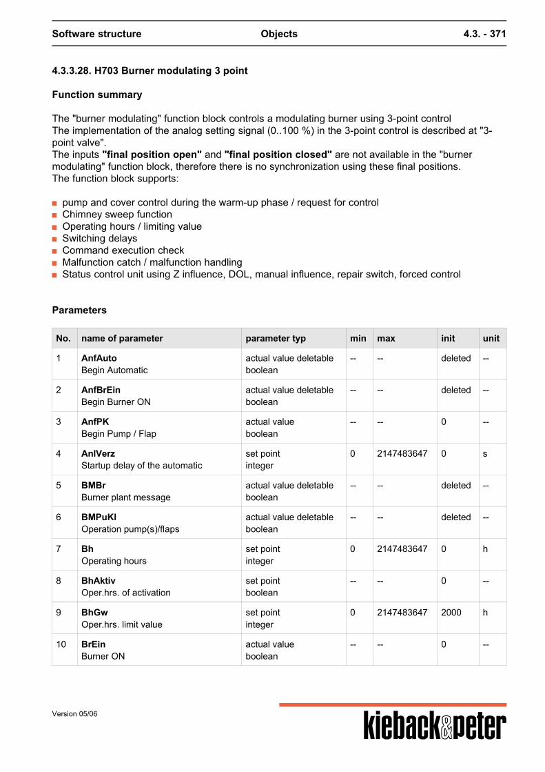
Software structure Objects 4.3. - 371
4.3.3.28. H703 Burner modulating 3 point
Function summary
The "burner modulating" function block controls a modulating burner using 3-point controlThe implementation of the analog setting signal (0..100 %) in the 3-point control is described at "3-point valve".The inputs "final position open" and "final position closed" are not available in the "burnermodulating" function block, therefore there is no synchronization using these final positions.The function block supports:
pump and cover control during the warm-up phase / request for control Chimney sweep function Operating hours / limiting value Switching delays Command execution check Malfunction catch / malfunction handling Status control unit using Z influence, DOL, manual influence, repair switch, forced control
Parameters
No. name of parameter parameter typ min max init unit
1 AnfAutoBegin Automatic
actual value deletableboolean
-- -- deleted --
2 AnfBrEinBegin Burner ON
actual value deletableboolean
-- -- deleted --
3 AnfPKBegin Pump / Flap
actual valueboolean
-- -- 0 --
4 AnlVerzStartup delay of the automatic
set pointinteger
0 2147483647 0 s
5 BMBrBurner plant message
actual value deletableboolean
-- -- deleted --
6 BMPuKlOperation pump(s)/flaps
actual value deletableboolean
-- -- deleted --
7 BhOperating hours
set pointinteger
0 2147483647 0 h
8 BhAktivOper.hrs. of activation
set pointboolean
-- -- 0 --
9 BhGwOper.hrs. limit value
set pointinteger
0 2147483647 2000 h
10 BrEinBurner ON
actual valueboolean
-- -- 0 --
Version 05/06
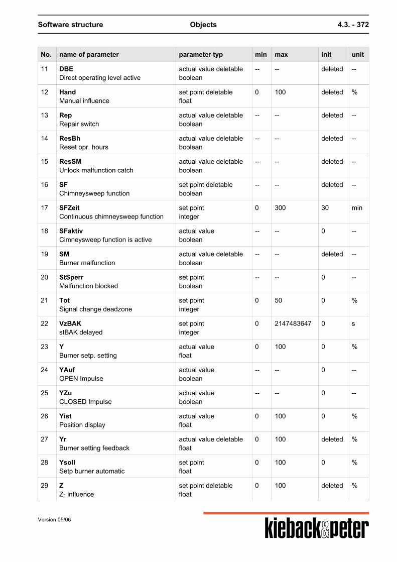
Software structure Objects 4.3. - 372
No. name of parameter parameter typ min max init unit
11 DBEDirect operating level active
actual value deletableboolean
-- -- deleted --
12 HandManual influence
set point deletablefloat
0 100 deleted %
13 RepRepair switch
actual value deletableboolean
-- -- deleted --
14 ResBhReset opr. hours
actual value deletableboolean
-- -- deleted --
15 ResSMUnlock malfunction catch
actual value deletableboolean
-- -- deleted --
16 SFChimneysweep function
set point deletableboolean
-- -- deleted --
17 SFZeitContinuous chimneysweep function
set pointinteger
0 300 30 min
18 SFaktivCimneysweep function is active
actual valueboolean
-- -- 0 --
19 SMBurner malfunction
actual value deletableboolean
-- -- deleted --
20 StSperrMalfunction blocked
set pointboolean
-- -- 0 --
21 TotSignal change deadzone
set pointinteger
0 50 0 %
22 VzBAKstBAK delayed
set pointinteger
0 2147483647 0 s
23 YBurner setp. setting
actual valuefloat
0 100 0 %
24 YAufOPEN Impulse
actual valueboolean
-- -- 0 --
25 YZuCLOSED Impulse
actual valueboolean
-- -- 0 --
26 YistPosition display
actual valuefloat
0 100 0 %
27 YrBurner setting feedback
actual value deletablefloat
0 100 deleted %
28 YsollSetp burner automatic
set pointfloat
0 100 0 %
29 ZZ- influence
set point deletablefloat
0 100 deleted %
Version 05/06
Software structure Objects 4.3. - 373
No. name of parameter parameter typ min max init unit
30 ZwForced control
set point deletableboolean
-- -- deleted --
31 ZwSwSetp. valve forced control
set point deletablefloat
0 100 deleted %
32 gBhLimit value error by opr.hrs.
actual valueboolean
-- -- 0 --
33 regBegin Control
actual valueboolean
-- -- 0 --
34 stBAKStatus BAK Burner
actual valueboolean
-- -- 0 --
35 tBAKTime BAK
set pointinteger
0 2147483647 30 s
36 tMotAufMotor runtime OPEN
set pointinteger
1 2147483647 120 s
37 tMotZuMotor runtime CLOSED
set pointinteger
1 2147483647 120 s
38 SMoutSMout
actual valueboolean
-- -- 0 --
Function description
There is a "position display" output. This indicates this value if the "position feedback signalburner" input is occupied. If this acknowledgement is not occupied the value of the "target positionburner" is used. This may come from "Target burner position in automatic operation", "Zinfluence", "set point forced control" or "manual influence", i.e. from the input with the highestactive priority.
Pump and cover control during the warm-up phase / request for control
If the burner is to be switched on the "pump/cover request" is first set to 1.Then there is a pause for the "operational message pump/cover" = 1 if this input is wired.At the same time as "request pump/cover" the "request control" is set to 1. This signals thesubsequent control beyond the hardware object that the burner is standing by to produce heat. If thenthe signal "request burner on" is set to 1 by the control and "operational message pump / cover"=1, the burner is switched on ("burner on"=1).
For "operational message pump/cover" this does not include a command executioncheck as "request pump / cover" should always be linked to a "pump" or "cover"hardware object that contains its own command execution check.
Version 05/06
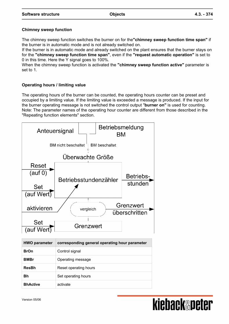
Software structure Objects 4.3. - 374
Chimney sweep function
The chimney sweep function switches the burner on for the"chimney sweep function time span" ifthe burner is in automatic mode and is not already switched on.If the burner is in automatic mode and already switched on the plant ensures that the burner stays onfor the "chimney sweep function time span", even if the "request automatic operation" is set to0 in this time. Here the Y signal goes to 100%.When the chimney sweep function is activated the "chimney sweep function active" parameter isset to 1.
Operating hours / limiting value
The operating hours of the burner can be counted, the operating hours counter can be preset andoccupied by a limiting value. If the limiting value is exceeded a message is produced. If the input forthe burner operating message is not switched the control output "burner on" is used for counting.Note: The parameter names of the operating hour counter are different from those described in the"Repeating function elements" section.
HWO parameter corresponding general operating hour parameter
BrOn Control signal
BMBr Operating message
ResBh Reset operating hours
Bh Set operating hours
BhActive activate
Version 05/06
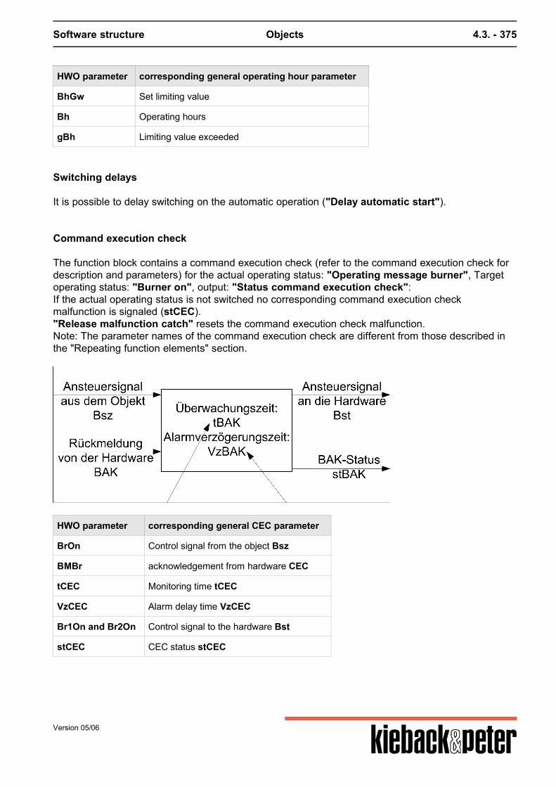
Software structure Objects 4.3. - 375
HWO parameter corresponding general operating hour parameter
BhGw Set limiting value
Bh Operating hours
gBh Limiting value exceeded
Switching delays
It is possible to delay switching on the automatic operation ("Delay automatic start").
Command execution check
The function block contains a command execution check (refer to the command execution check fordescription and parameters) for the actual operating status: "Operating message burner", Targetoperating status: "Burner on", output: "Status command execution check":If the actual operating status is not switched no corresponding command execution checkmalfunction is signaled (stCEC)."Release malfunction catch" resets the command execution check malfunction.Note: The parameter names of the command execution check are different from those described inthe "Repeating function elements" section.
HWO parameter corresponding general CEC parameter
BrOn Control signal from the object Bsz
BMBr acknowledgement from hardware CEC
tCEC Monitoring time tCEC
VzCEC Alarm delay time VzCEC
Br1On and Br2On Control signal to the hardware Bst
stCEC CEC status stCEC
Version 05/06
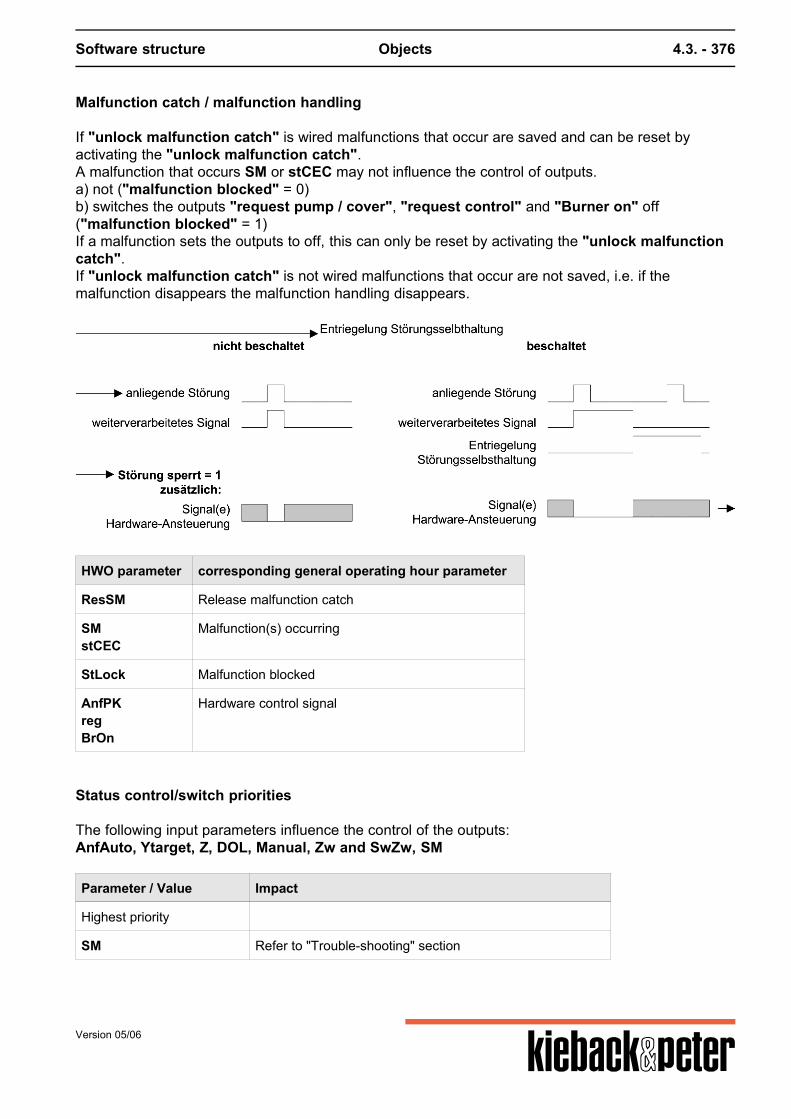
Software structure Objects 4.3. - 376
Malfunction catch / malfunction handling
If "unlock malfunction catch" is wired malfunctions that occur are saved and can be reset byactivating the "unlock malfunction catch".A malfunction that occurs SM or stCEC may not influence the control of outputs.a) not ("malfunction blocked" = 0)b) switches the outputs "request pump / cover", "request control" and "Burner on" off("malfunction blocked" = 1)If a malfunction sets the outputs to off, this can only be reset by activating the "unlock malfunctioncatch".If "unlock malfunction catch" is not wired malfunctions that occur are not saved, i.e. if themalfunction disappears the malfunction handling disappears.
HWO parameter corresponding general operating hour parameter
ResSM Release malfunction catch
SMstCEC
Malfunction(s) occurring
StLock Malfunction blocked
AnfPKregBrOn
Hardware control signal
Status control/switch priorities
The following input parameters influence the control of the outputs:AnfAuto, Ytarget, Z, DOL, Manual, Zw and SwZw, SM
Parameter / Value Impact
Highest priority
SM Refer to "Trouble-shooting" section
Version 05/06
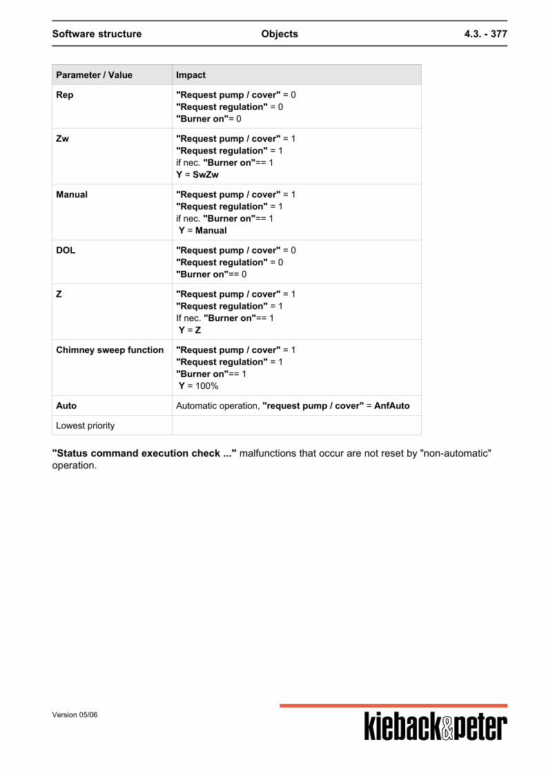
Software structure Objects 4.3. - 377
Parameter / Value Impact
Rep "Request pump / cover" = 0"Request regulation" = 0"Burner on"= 0
Zw "Request pump / cover" = 1"Request regulation" = 1if nec. "Burner on"== 1Y = SwZw
Manual "Request pump / cover" = 1"Request regulation" = 1if nec. "Burner on"== 1 Y = Manual
DOL "Request pump / cover" = 0"Request regulation" = 0"Burner on"== 0
Z "Request pump / cover" = 1"Request regulation" = 1If nec. "Burner on"== 1 Y = Z
Chimney sweep function "Request pump / cover" = 1"Request regulation" = 1"Burner on"== 1 Y = 100%
Auto Automatic operation, "request pump / cover" = AnfAuto
Lowest priority
"Status command execution check ..." malfunctions that occur are not reset by "non-automatic"operation.
Version 05/06
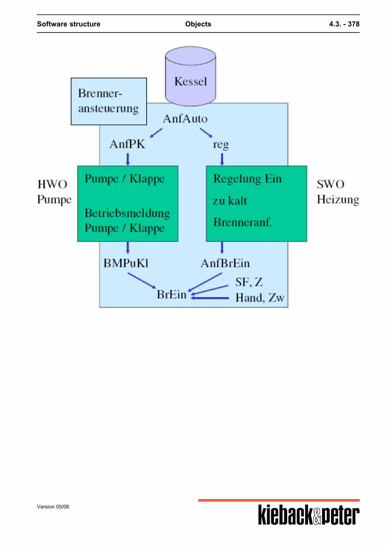
Software structure Objects 4.3. - 378
Version 05/06
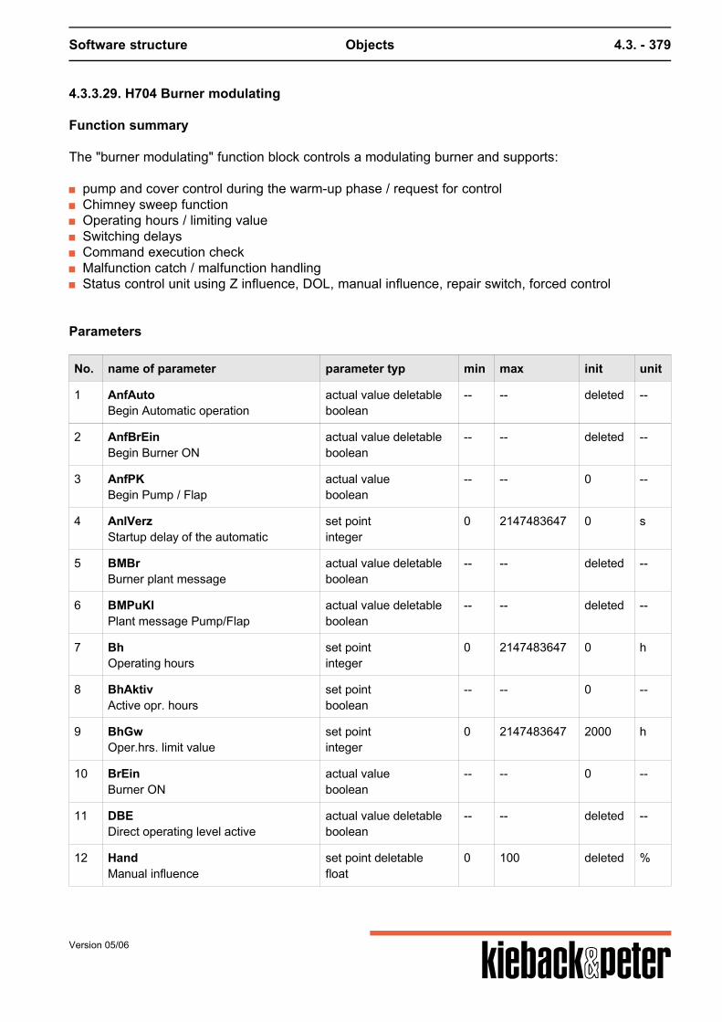
Software structure Objects 4.3. - 379
4.3.3.29. H704 Burner modulating
Function summary
The "burner modulating" function block controls a modulating burner and supports:
pump and cover control during the warm-up phase / request for control Chimney sweep function Operating hours / limiting value Switching delays Command execution check Malfunction catch / malfunction handling Status control unit using Z influence, DOL, manual influence, repair switch, forced control
Parameters
No. name of parameter parameter typ min max init unit
1 AnfAutoBegin Automatic operation
actual value deletableboolean
-- -- deleted --
2 AnfBrEinBegin Burner ON
actual value deletableboolean
-- -- deleted --
3 AnfPKBegin Pump / Flap
actual valueboolean
-- -- 0 --
4 AnlVerzStartup delay of the automatic
set pointinteger
0 2147483647 0 s
5 BMBrBurner plant message
actual value deletableboolean
-- -- deleted --
6 BMPuKlPlant message Pump/Flap
actual value deletableboolean
-- -- deleted --
7 BhOperating hours
set pointinteger
0 2147483647 0 h
8 BhAktivActive opr. hours
set pointboolean
-- -- 0 --
9 BhGwOper.hrs. limit value
set pointinteger
0 2147483647 2000 h
10 BrEinBurner ON
actual valueboolean
-- -- 0 --
11 DBEDirect operating level active
actual value deletableboolean
-- -- deleted --
12 HandManual influence
set point deletablefloat
0 100 deleted %
Version 05/06
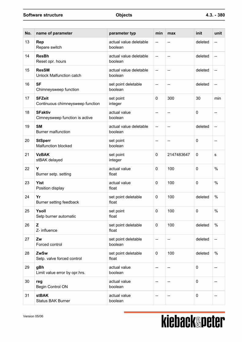
Software structure Objects 4.3. - 380
No. name of parameter parameter typ min max init unit
13 RepRepare switch
actual value deletableboolean
-- -- deleted --
14 ResBhReset opr. hours
actual value deletableboolean
-- -- deleted --
15 ResSMUnlock Malfunction catch
actual value deletableboolean
-- -- deleted --
16 SFChimneysweep function
set point deletableboolean
-- -- deleted --
17 SFZeitContinuous chimneysweep function
set pointinteger
0 300 30 min
18 SFaktivCimneysweep function is active
actual valueboolean
-- -- 0 --
19 SMBurner malfunction
actual value deletableboolean
-- -- deleted --
20 StSperrMalfunction blocked
set pointboolean
-- -- 0 --
21 VzBAKstBAK delayed
set pointinteger
0 2147483647 0 s
22 YBurner setp. setting
actual valuefloat
0 100 0 %
23 YistPosition display
actual valuefloat
0 100 0 %
24 YrBurner setting feedback
set point deletablefloat
0 100 deleted %
25 YsollSetp burner automatic
set pointfloat
0 100 0 %
26 ZZ- influence
set point deletablefloat
0 100 deleted %
27 ZwForced control
set point deletableboolean
-- -- deleted --
28 ZwSwSetp. valve forced control
set point deletablefloat
0 100 deleted %
29 gBhLimit value error by opr.hrs.
actual valueboolean
-- -- 0 --
30 regBegin Control ON
actual valueboolean
-- -- 0 --
31 stBAKStatus BAK Burner
actual valueboolean
-- -- 0 --
Version 05/06
Software structure Objects 4.3. - 381
No. name of parameter parameter typ min max init unit
32 tBAKTime BAK
set pointinteger
0 2147483647 30 s
33 SMoutSMout
actual valueboolean
-- -- 0 --
Function description
There is a "position display" output. This indicates this value if the "position feedback signalburner" input is occupied. If this acknowledgement is not occupied the value of the "target positionburner" is used. This may come from "Target burner position in automatic operation", "Zinfluence", "set point forced control" or "manual influence", i.e. from the input with the highestactive priority.
Pump and cover control during the warm-up phase / request for control
If the burner is to be switched on the "pump/cover request" is first set to 1.Then there is a pause for the "operational message pump/cover" = 1 if this input is wired.At the same time as "request pump/cover" the "request control" is set to 1. This signals thesubsequent control beyond the hardware object that the burner is standing by to produce heat. If thenthe signal "request burner on" is set to 1 by the control and "operational message pump / cover"=1, the burner is switched on ("burner on"=1).
For "operational message pump/cover" this does not include a command executioncheck as "request pump / cover" should always be linked to a "pump" or "cover"hardware object that contains its own command execution check.
Chimney sweep function
The chimney sweep function switches the burner on for the"chimney sweep function time span" ifthe burner is in automatic mode and is not already switched on.If the burner is in automatic mode and already switched on the plant ensures that the burner stays onfor the "chimney sweep function time span", even if the "request automatic operation" is set to0 in this time. Here the Y signal goes to 100%.When the chimney sweep function is activated the "chimney sweep function active" parameter isset to 1.
Operating hours / limiting value
The operating hours of the burner can be counted, the operating hours counter can be preset andoccupied by a limiting value. If the limiting value is exceeded a message is produced. If the input forthe burner operating message is not switched the control output "burner on" is used for counting.
Version 05/06
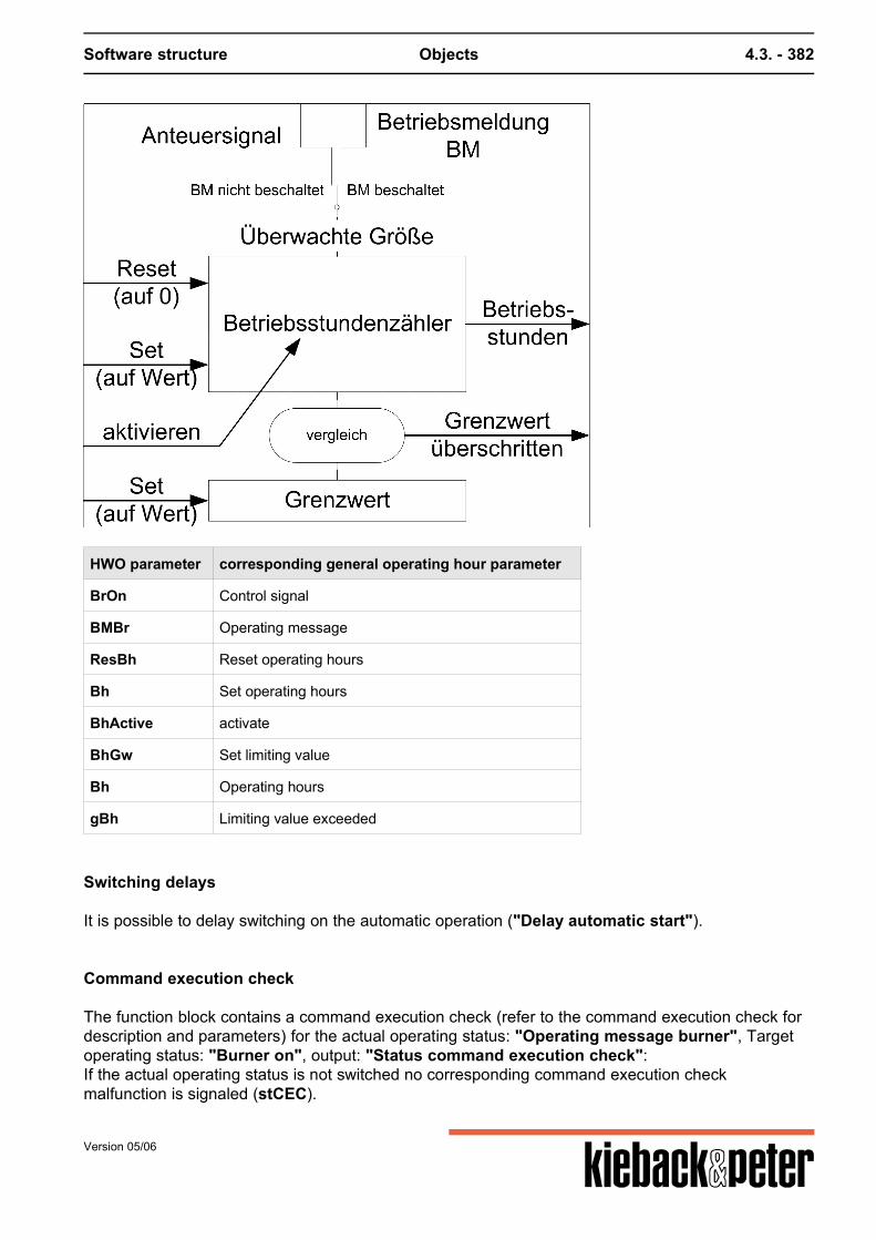
Software structure Objects 4.3. - 382
HWO parameter corresponding general operating hour parameter
BrOn Control signal
BMBr Operating message
ResBh Reset operating hours
Bh Set operating hours
BhActive activate
BhGw Set limiting value
Bh Operating hours
gBh Limiting value exceeded
Switching delays
It is possible to delay switching on the automatic operation ("Delay automatic start").
Command execution check
The function block contains a command execution check (refer to the command execution check fordescription and parameters) for the actual operating status: "Operating message burner", Targetoperating status: "Burner on", output: "Status command execution check":If the actual operating status is not switched no corresponding command execution checkmalfunction is signaled (stCEC).
Version 05/06
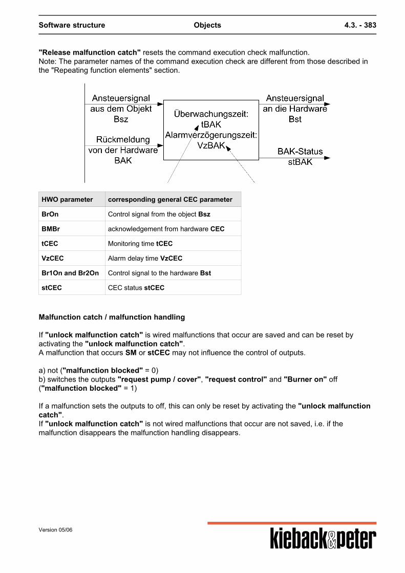
Software structure Objects 4.3. - 383
"Release malfunction catch" resets the command execution check malfunction.Note: The parameter names of the command execution check are different from those described inthe "Repeating function elements" section.
HWO parameter corresponding general CEC parameter
BrOn Control signal from the object Bsz
BMBr acknowledgement from hardware CEC
tCEC Monitoring time tCEC
VzCEC Alarm delay time VzCEC
Br1On and Br2On Control signal to the hardware Bst
stCEC CEC status stCEC
Malfunction catch / malfunction handling
If "unlock malfunction catch" is wired malfunctions that occur are saved and can be reset byactivating the "unlock malfunction catch".A malfunction that occurs SM or stCEC may not influence the control of outputs.
a) not ("malfunction blocked" = 0)b) switches the outputs "request pump / cover", "request control" and "Burner on" off("malfunction blocked" = 1) If a malfunction sets the outputs to off, this can only be reset by activating the "unlock malfunctioncatch".If "unlock malfunction catch" is not wired malfunctions that occur are not saved, i.e. if themalfunction disappears the malfunction handling disappears.
Version 05/06
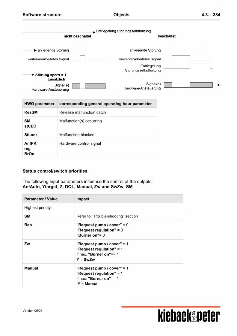
Software structure Objects 4.3. - 384
HWO parameter corresponding general operating hour parameter
ResSM Release malfunction catch
SMstCEC
Malfunction(s) occurring
StLock Malfunction blocked
AnfPKregBrOn
Hardware control signal
Status control/switch priorities
The following input parameters influence the control of the outputs:AnfAuto, Ytarget, Z, DOL, Manual, Zw and SwZw, SM
Parameter / Value Impact
Highest priority
SM Refer to "Trouble-shooting" section
Rep "Request pump / cover" = 0"Request regulation" = 0"Burner on"= 0
Zw "Request pump / cover" = 1"Request regulation" = 1if nec. "Burner on"== 1Y = SwZw
Manual "Request pump / cover" = 1"Request regulation" = 1if nec. "Burner on"== 1 Y = Manual
Version 05/06
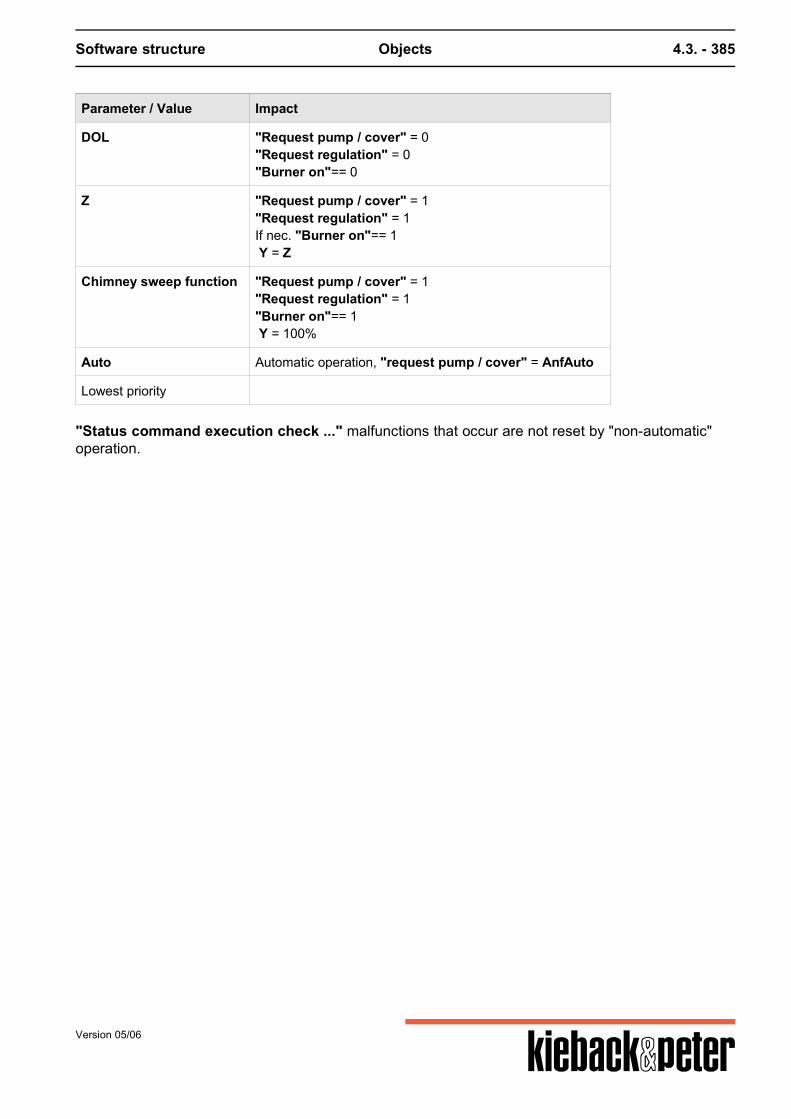
Software structure Objects 4.3. - 385
Parameter / Value Impact
DOL "Request pump / cover" = 0"Request regulation" = 0"Burner on"== 0
Z "Request pump / cover" = 1"Request regulation" = 1If nec. "Burner on"== 1 Y = Z
Chimney sweep function "Request pump / cover" = 1"Request regulation" = 1"Burner on"== 1 Y = 100%
Auto Automatic operation, "request pump / cover" = AnfAuto
Lowest priority
"Status command execution check ..." malfunctions that occur are not reset by "non-automatic"operation.
Version 05/06

Software structure Objects 4.3. - 386
Version 05/06
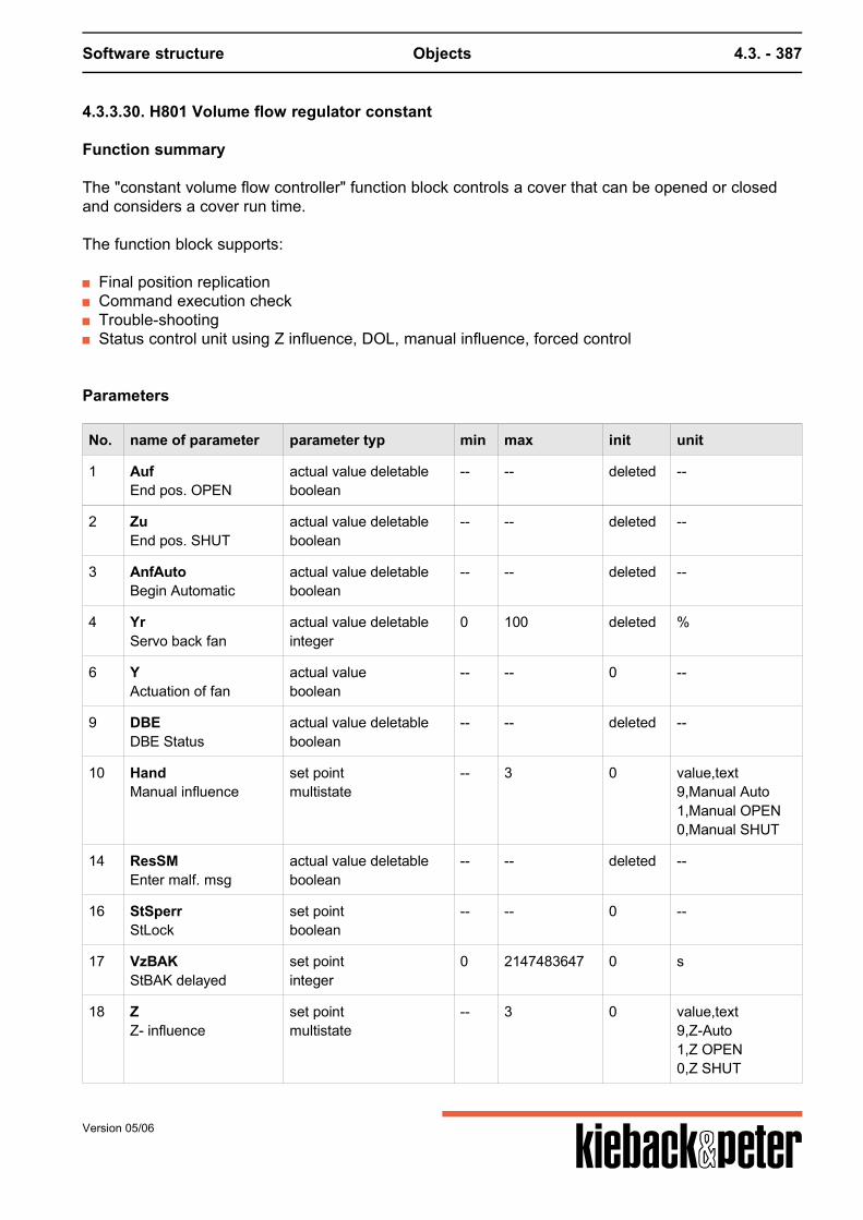
Software structure Objects 4.3. - 387
4.3.3.30. H801 Volume flow regulator constant
Function summary
The "constant volume flow controller" function block controls a cover that can be opened or closedand considers a cover run time.
The function block supports:
Final position replication Command execution check Trouble-shooting Status control unit using Z influence, DOL, manual influence, forced control
Parameters
No. name of parameter parameter typ min max init unit
1 AufEnd pos. OPEN
actual value deletableboolean
-- -- deleted --
2 ZuEnd pos. SHUT
actual value deletableboolean
-- -- deleted --
3 AnfAutoBegin Automatic
actual value deletableboolean
-- -- deleted --
4 YrServo back fan
actual value deletableinteger
0 100 deleted %
6 YActuation of fan
actual valueboolean
-- -- 0 --
9 DBEDBE Status
actual value deletableboolean
-- -- deleted --
10 HandManual influence
set pointmultistate
-- 3 0 value,text9,Manual Auto1,Manual OPEN0,Manual SHUT
14 ResSMEnter malf. msg
actual value deletableboolean
-- -- deleted --
16 StSperrStLock
set pointboolean
-- -- 0 --
17 VzBAKStBAK delayed
set pointinteger
0 2147483647 0 s
18 ZZ- influence
set pointmultistate
-- 3 0 value,text9,Z-Auto1,Z OPEN0,Z SHUT
Version 05/06
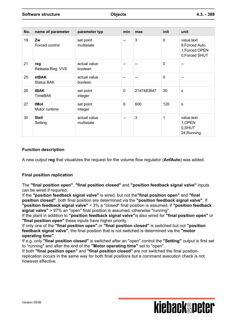
Software structure Objects 4.3. - 388
No. name of parameter parameter typ min max init unit
19 ZwForced control
set pointmultistate
-- 3 0 value,text9,Forced Auto1,Forced OPEN0,Forced SHUT
21 regRelease.Reg. VVS
actual valueboolean
-- -- 0 --
25 stBAKStatus BAK
actual valueboolean
-- -- 0 --
26 tBAKTimeBAK
set pointinteger
0 2147483647 30 s
27 tMotMotor runtime
set pointinteger
0 600 120 s
30 StellSetting
actual valuemultistate
-- 3 1 value,text1,OPEN0,SHUT24,Running
Function description
A new output reg that visualizes the request for the volume flow regulator (AnfAuto) was added.
Final position replication
The "final position open", "final position closed" and "position feedback signal valve" inputscan be wired if required.If the "position feedback signal valve" is wired, but not the"final position open" and "finalposition closed", both final position are determined via the "position feedback signal valve". If"position feedback signal valve" < 3% a "closed" final position is assumed, if "position feedbacksignal valve" > 97% an "open" final position is assumed, otherwise "running".If the plant in addition to "position feedback signal valve"is also wired for "final position open" or"final position open" these inputs have higher priority.If only one of the "final position open" or "final position closed" is switched but not "positionfeedback signal valve", the final position that is not switched is determined via the "motoroperating time".If e.g. only "final position closed" is switched after an "open" control the "Setting" output is first setto "running" and after the end of the "Motor operating time" set to "open".If both "final position open" and "final position closed" are not switched the final position-replication occurs in the same way for both final positions but a command execution check is nothowever effective.
Version 05/06
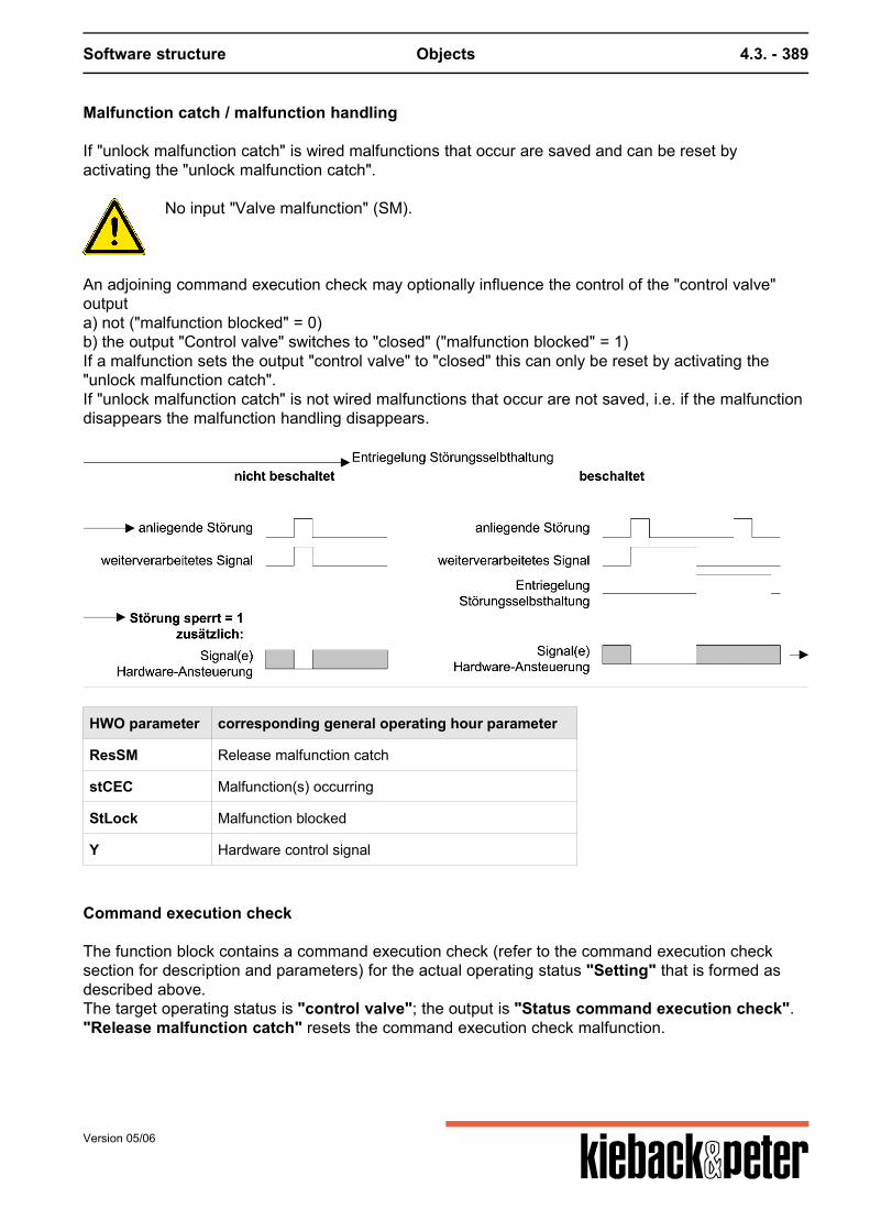
Software structure Objects 4.3. - 389
Malfunction catch / malfunction handling
If "unlock malfunction catch" is wired malfunctions that occur are saved and can be reset byactivating the "unlock malfunction catch".
No input "Valve malfunction" (SM).
An adjoining command execution check may optionally influence the control of the "control valve"outputa) not ("malfunction blocked" = 0)b) the output "Control valve" switches to "closed" ("malfunction blocked" = 1)If a malfunction sets the output "control valve" to "closed" this can only be reset by activating the"unlock malfunction catch".If "unlock malfunction catch" is not wired malfunctions that occur are not saved, i.e. if the malfunctiondisappears the malfunction handling disappears.
HWO parameter corresponding general operating hour parameter
ResSM Release malfunction catch
stCEC Malfunction(s) occurring
StLock Malfunction blocked
Y Hardware control signal
Command execution check
The function block contains a command execution check (refer to the command execution checksection for description and parameters) for the actual operating status "Setting" that is formed asdescribed above.The target operating status is "control valve"; the output is "Status command execution check"."Release malfunction catch" resets the command execution check malfunction.
Version 05/06
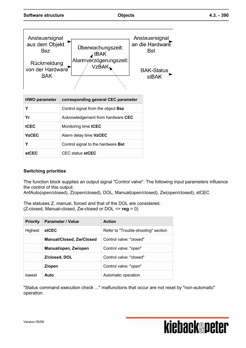
Software structure Objects 4.3. - 390
HWO parameter corresponding general CEC parameter
Y Control signal from the object Bsz
Yr Acknowledgement from hardware CEC
tCEC Monitoring time tCEC
VzCEC Alarm delay time VzCEC
Y Control signal to the hardware Bst
stCEC CEC status stCEC
Switching priorities
The function block supplies an output signal "Control valve". The following input parameters influencethe control of this output:AnfAuto(open/closed), Z(open/closed), DOL, Manual(open/closed), Zw(open/closed), stCEC The statuses Z, manual, forced and that of the DOL are considered.(Z-closed, Manual-closed, Zw-closed or DOL => reg = 0)
Priority Parameter / Value Action
Highest stCEC Refer to "Trouble-shooting" section
Manual/Closed, Zw/Closed Control valve: "closed"
Manual/open, Zw/open Control valve: "open"
Z/closed, DOL Control valve: "closed"
Z/open Control valve: "open"
lowest Auto Automatic operation
"Status command execution check ..." malfunctions that occur are not reset by "non-automatic"operation.
Version 05/06
Software structure Objects 4.3. - 391
4.3.3.31. H802 Volume flow regulator constant
Function summary
The "volume flow regulator constant" function block controls a constant cover with target setting of0...100%. The function block supports:
Trouble-shooting/malfunction catch Status control unit using Z influence, DOL, manual influence, forced control
Parameters
No. name of parameter parameter typ min max init unit
1 AufEnd pos. OPEN
actual value deletableboolean
-- -- deleted --
2 ZuEnd pos. SHUT
actual value deletableboolean
-- -- deleted --
3 YsollYset
set pointfloat
0 100 0 %
4 YrServo back fan
actual value deletablefloat
0 100 deleted %
5 YistSetting no.
actual valuefloat
0 100 0 %
6 YSetp. valve
actual value deletablefloat
0 100 deleted %
7 AnfAutoBegin Automatic
actual value deletableboolean
-- -- deleted --
9 DBEDBE Status
actual value deletableboolean
-- -- deleted --
10 HandManual influence
set point deletablefloat
0 100 deleted %
14 ResSMEnter malf. msg
actual value deletableboolean
-- -- deleted --
15 SMValve malf.
actual value deletableboolean
-- -- deleted --
16 StSperrStLock
set pointboolean
-- -- 0 --
18 ZZ- influence
set point deletableinteger
0 100 deleted %
Version 05/06
Software structure Objects 4.3. - 392
No. name of parameter parameter typ min max init unit
19 ZwForced control
actual value deletableboolean
-- -- deleted --
20 SwZwSetpoint forced control
set pointinteger
0 100 100 %
21 regRelease.Reg. VVS
actual valueboolean
-- -- 0 --
22 SMoutSMout
actual valueboolean
-- -- 0 --
Function description
Parameter "AnfAuto" was added in which for example the "release control" for a PID control can beset. The corresponding output regVVS therefore produces a release for the VVS control. If amalfunction occurs this release is set to zero.
Position display
There is a "position display" output. This indicates this value if the "position feedback signalvalve" input is occupied. If this acknowledgement is not occupied the value of the "target positionvalve" is used. This may come from "Target valve position in automatic operation", "Zinfluence", "set point forced control" or "manual influence", i.e. from the input with the highestactive priority.
Malfunction catch / malfunction handling
If "unlock malfunction catch" is wired malfunctions that occur are saved and can be reset byactivating the "unlock malfunction catch".A malfunction that occurs SM may not influence the control of outputYa) not ("malfunction blocked" = 0)b) sets the output Y to 0% ("malfunction blocked" = 1)If a malfunction sets the output Y to 0% this can only be reset by activating the "Unlock malfunctioncatch".If "unlock malfunction catch" is not wired malfunctions that occur are not saved, i.e. if themalfunction disappears the malfunction handling disappears.
Version 05/06

Software structure Objects 4.3. - 393
HWO parameter corresponding general operating hour parameter
ResSM Release malfunction catch
SM Malfunction(s) occurring
StLock Malfunction blocked
Y Hardware control signal
Switching priorities
The function block supplies an output signal "Target setting valve". The following input parametersinfluence the control of this output:Ytarget, Z, DOL, Manual, Zw and ZwSw, SM
Priority Parameter / Value Action
Highest SM See "effects of malfunctions on operating behavior" section.
Zw Y = ZwSw
Manual Y = Manual
DOL Y = 0%
Z Y = Z
lowest Auto Y = Ytarget
Version 05/06
Software structure Objects 4.3. - 394
4.3.3.32. H901 Pump single stage
Function summary
The "pump single stage" function block controls a single-stage pump and supports:
Switching delays Pump blocking protection Operating hours / limiting value Command execution check Malfunction catch / malfunction handling Status control unit using Z influence, direct operating level(DOL), manual influence, repair switch,
forced control
Attention! "malfunction blocked"
An important note:How does "malfunction blocked" work? The "malfunction blocked" parameter can be set to yes or no. If a malfunction occurs either theoutput is switched off or the malfunction does not affect the outputs. The malfunction catch is activated by linking a source on ResSM (Reset malfunction message).Only in this case is it possible to reset a malfunction message. Here a link creates a function.
Parameters
No. name of parameter parameter typ min max init unit
1 AnfAutoBegin Automatic
actual value deletableboolean
-- -- deleted --
2 BMRe: msg. Pu
actual value deletableboolean
-- -- deleted --
3 pbsStatus blocking prot.
actual valueboolean
-- -- 0 --
5 HandManual
set pointmultistate
-- 3 0 value,text9,Auto0,OFF1,ON
7 StSperrMalfunction blocked
set pointboolean
-- -- 0 --
8 ResSMUnlock Fault
actual value deletableboolean
-- -- deleted --
9 regBegin Control
actual valueboolean
-- -- 0 --
Version 05/06
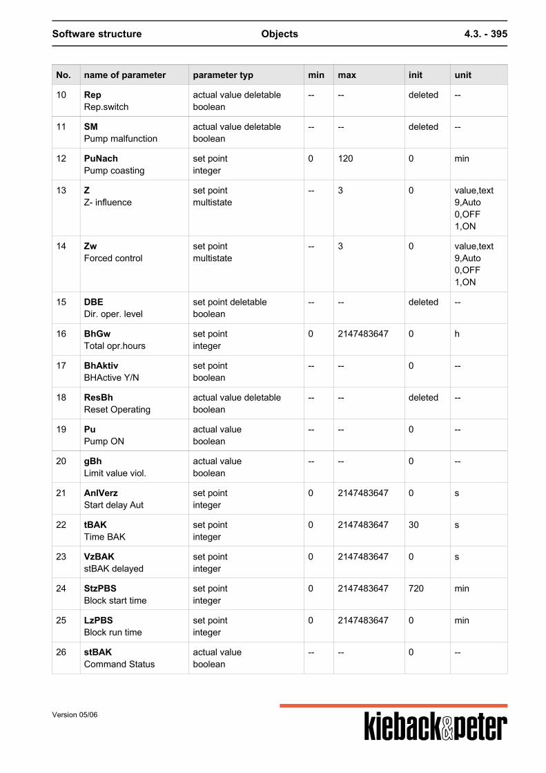
Software structure Objects 4.3. - 395
No. name of parameter parameter typ min max init unit
10 RepRep.switch
actual value deletableboolean
-- -- deleted --
11 SMPump malfunction
actual value deletableboolean
-- -- deleted --
12 PuNachPump coasting
set pointinteger
0 120 0 min
13 ZZ- influence
set pointmultistate
-- 3 0 value,text9,Auto0,OFF1,ON
14 ZwForced control
set pointmultistate
-- 3 0 value,text9,Auto0,OFF1,ON
15 DBEDir. oper. level
set point deletableboolean
-- -- deleted --
16 BhGwTotal opr.hours
set pointinteger
0 2147483647 0 h
17 BhAktivBHActive Y/N
set pointboolean
-- -- 0 --
18 ResBhReset Operating
actual value deletableboolean
-- -- deleted --
19 PuPump ON
actual valueboolean
-- -- 0 --
20 gBhLimit value viol.
actual valueboolean
-- -- 0 --
21 AnlVerzStart delay Aut
set pointinteger
0 2147483647 0 s
22 tBAKTime BAK
set pointinteger
0 2147483647 30 s
23 VzBAKstBAK delayed
set pointinteger
0 2147483647 0 s
24 StzPBSBlock start time
set pointinteger
0 2147483647 720 min
25 LzPBSBlock run time
set pointinteger
0 2147483647 0 min
26 stBAKCommand Status
actual valueboolean
-- -- 0 --
Version 05/06
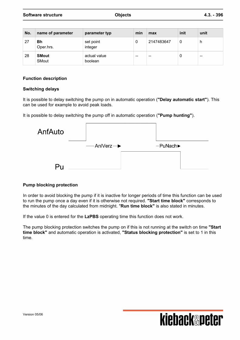
Software structure Objects 4.3. - 396
No. name of parameter parameter typ min max init unit
27 BhOper.hrs.
set pointinteger
0 2147483647 0 h
28 SMoutSMout
actual valueboolean
-- -- 0 --
Function description
Switching delays
It is possible to delay switching the pump on in automatic operation ("Delay automatic start"). Thiscan be used for example to avoid peak loads. It is possible to delay switching the pump off in automatic operation ("Pump hunting").
Pump blocking protection
In order to avoid blocking the pump if it is inactive for longer periods of time this function can be usedto run the pump once a day even if it is otherwise not required. "Start time block" corresponds tothe minutes of the day calculated from midnight. "Run time block" is also stated in minutes. If the value 0 is entered for the LzPBS operating time this function does not work. The pump blocking protection switches the pump on if this is not running at the switch on time "Starttime block" and automatic operation is activated, "Status blocking protection" is set to 1 in thistime.
Version 05/06
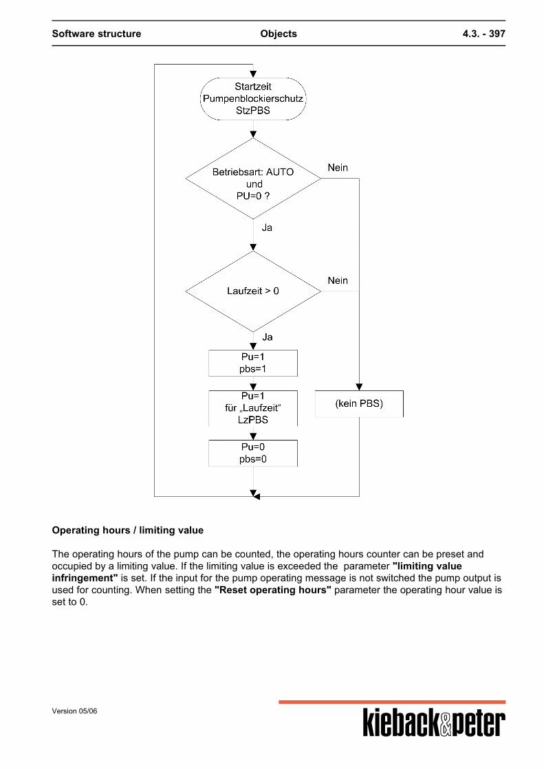
Software structure Objects 4.3. - 397
Operating hours / limiting value
The operating hours of the pump can be counted, the operating hours counter can be preset andoccupied by a limiting value. If the limiting value is exceeded the parameter "limiting valueinfringement" is set. If the input for the pump operating message is not switched the pump output isused for counting. When setting the "Reset operating hours" parameter the operating hour value isset to 0.
Version 05/06
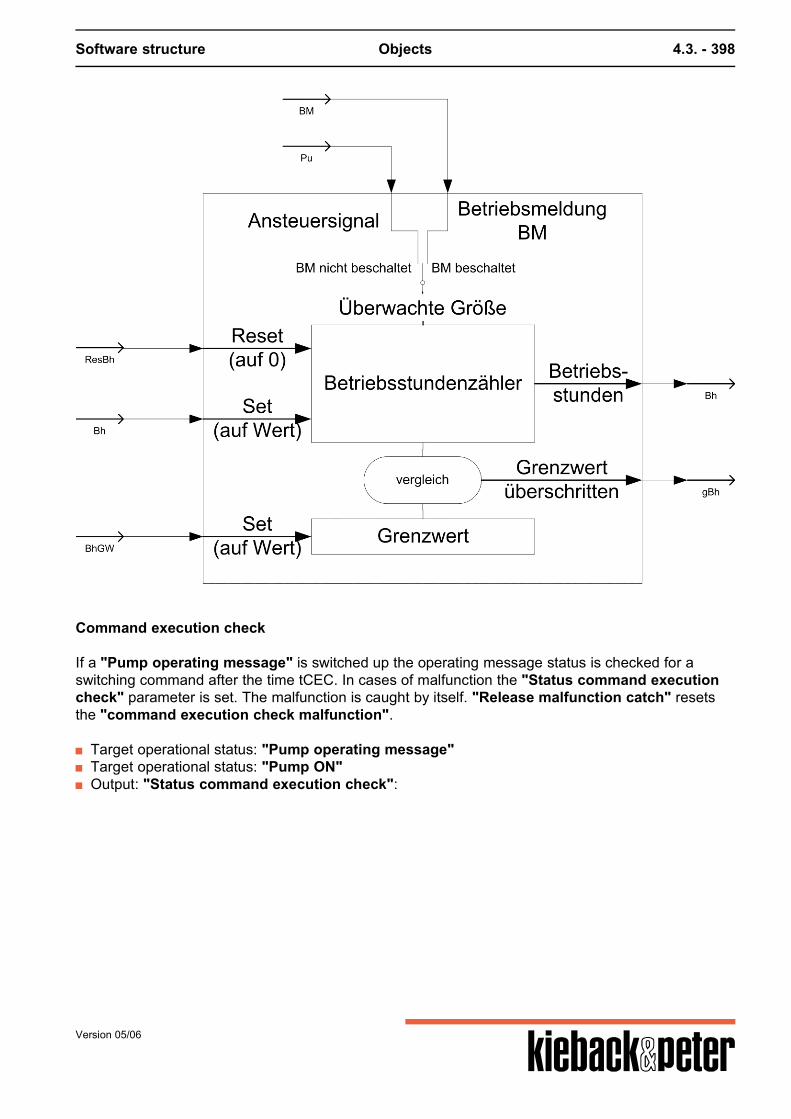
Software structure Objects 4.3. - 398
Command execution check
If a "Pump operating message" is switched up the operating message status is checked for aswitching command after the time tCEC. In cases of malfunction the "Status command executioncheck" parameter is set. The malfunction is caught by itself. "Release malfunction catch" resetsthe "command execution check malfunction".
Target operational status: "Pump operating message" Target operational status: "Pump ON" Output: "Status command execution check":
Version 05/06
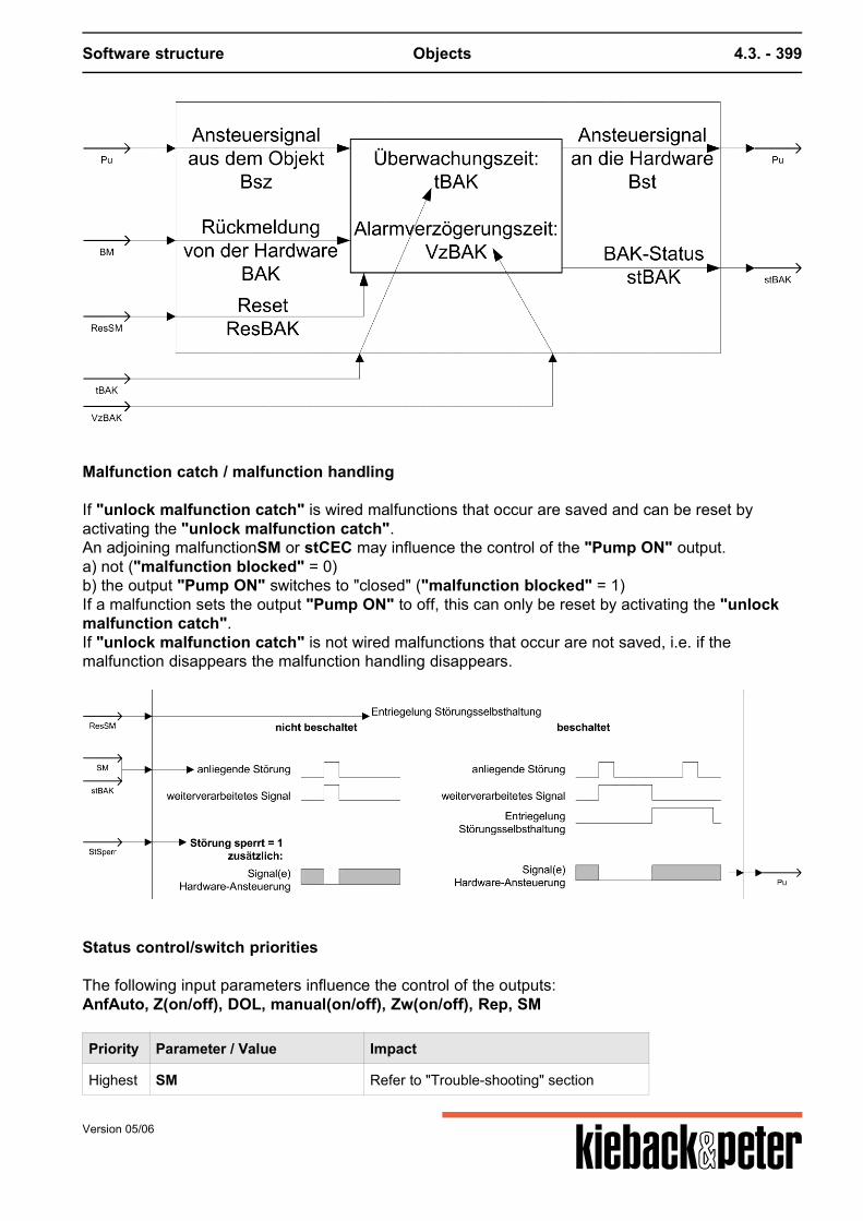
Software structure Objects 4.3. - 399
Malfunction catch / malfunction handling
If "unlock malfunction catch" is wired malfunctions that occur are saved and can be reset byactivating the "unlock malfunction catch".An adjoining malfunctionSM or stCEC may influence the control of the "Pump ON" output.a) not ("malfunction blocked" = 0)b) the output "Pump ON" switches to "closed" ("malfunction blocked" = 1)If a malfunction sets the output "Pump ON" to off, this can only be reset by activating the "unlockmalfunction catch".If "unlock malfunction catch" is not wired malfunctions that occur are not saved, i.e. if themalfunction disappears the malfunction handling disappears.
Status control/switch priorities
The following input parameters influence the control of the outputs:AnfAuto, Z(on/off), DOL, manual(on/off), Zw(on/off), Rep, SM
Priority Parameter / Value Impact
Highest SM Refer to "Trouble-shooting" section
Version 05/06

Software structure Objects 4.3. - 400
Priority Parameter / Value Impact
Manual/open, Zw/open, Rep Pu = 0
Manual/open, Zw/open Pu = 1
Z/closed, DOL Pu = 0
Z/On Pu = 1
lowest AnfAuto if AnfAuto = 1, then automatic operation
"Status command execution check ..." malfunctions that occur are not reset by "non-automatic"operation.
Request regulation
If the pump (not as a result of the pump blocking protection pbs) is switched on (PU=1) and theoperating message whose proper function is shown, the signal reg (request regulation) is set to 1.
Version 05/06
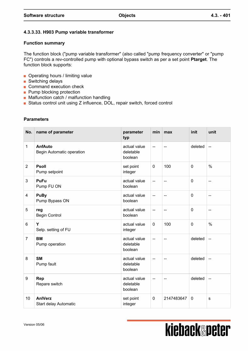
Software structure Objects 4.3. - 401
4.3.3.33. H903 Pump variable transformer
Function summary
The function block ("pump variable transformer" (also called "pump frequency converter" or "pumpFC") controls a rev-controlled pump with optional bypass switch as per a set point Ptarget. Thefunction block supports:
Operating hours / limiting value Switching delays Command execution check Pump blocking protection Malfunction catch / malfunction handling Status control unit using Z influence, DOL, repair switch, forced control
Parameters
No. name of parameter parametertyp
min max init unit
1 AnfAutoBegin Automatic operation
actual valuedeletableboolean
-- -- deleted --
2 PsollPump setpoint
set pointinteger
0 100 0 %
3 PuFuPump FU ON
actual valueboolean
-- -- 0 --
4 PuByPump Bypass ON
actual valueboolean
-- -- 0 --
5 regBegin Control
actual valueboolean
-- -- 0 --
6 YSetp. setting of FU
actual valueinteger
0 100 0 %
7 BMPump operation
actual valuedeletableboolean
-- -- deleted --
8 SMPump fault
actual valuedeletableboolean
-- -- deleted --
9 RepRepare switch
actual valuedeletableboolean
-- -- deleted --
10 AnlVerzStart delay Automatic
set pointinteger
0 2147483647 0 s
Version 05/06
Software structure Objects 4.3. - 402
No. name of parameter parametertyp
min max init unit
11 BMFuFU operation
actual valuedeletableboolean
-- -- deleted --
12 BhOper.hrs. presetting
set pointinteger
0 2147483647 0 h
13 BhAktivOper.hrs.cnt. activation
set pointboolean
-- -- 0 --
14 BhGwOper.hrs. limit value
set pointinteger
0 2147483647 0 h
15 ByAktivBypass activation
actual valueboolean
-- -- 0 --
16 DBEDirect operating level active
actual valuedeletableboolean
-- -- deleted --
17 HandManual switch (Autom./OFF/FU ON/BpassON)
set pointmultistate
-- 4 0 value,text9,Auto0,OFF21,FU_ON31,BY_ON
18 LzPBSRun time blocking prot.
set pointinteger
0 2147483647 0 min
19 PuNachPump coasting
set pointinteger
0 120 0 min
20 RMAnaServo feedback from the FU
actual valuedeletableinteger
0 100 deleted %
21 ResBhReset oper. hours
actual valuedeletableboolean
-- -- deleted --
22 ResSMUnlock malfunction catch
actual valuedeletableboolean
-- -- deleted --
23 RzByFuSwitch-back time bypass FU
actual valueinteger
0 120 30 s
24 SMFuMalfunction FU
actual valuedeletableboolean
-- -- deleted --
25 StFuByMalf. FU requires bypass
set pointboolean
-- -- 0 --
Version 05/06
Software structure Objects 4.3. - 403
No. name of parameter parametertyp
min max init unit
26 StFuSperMalf. FU blocked
set pointboolean
-- -- 0 --
27 StSperrMalfunction blocked
set pointboolean
-- -- 0 --
28 StzPBSStart time blocking prot.
set pointinteger
0 2147483647 720 min
29 VzBAKstBAK delayed
actual valueinteger
0 2147483647 0 s
30 VzBAKFustBAKFu delayed
set pointinteger
0 2147483647 0 s
31 ZZ- influence
set pointmultistate
-- 4 0 value,text9,Auto0,OFF21,FU_ON31,BY_ON
32 ZWForced control
set pointmultistate
-- 3 0 value,text9,Auto0,OFF1,ON
33 ZsPump Z-influence setpoint
set pointinteger
0 100 0 %
34 ZwSwSetpoint forced control
set pointinteger
0 100 0 %
35 gBhLimit value error by opr.hrs.
actual valueboolean
-- -- 0 --
36 pbsBlocking prot. active
actual valueboolean
-- -- 0 --
37 stBAKStatus pump command exe control
actual valueboolean
-- -- 0 --
38 stBAKFuStatus FU command exe control
actual valueboolean
-- -- 0 --
39 tBAKTime BAK
set pointinteger
0 2147483647 30 s
40 tBAKFuTime BAKFu
set pointinteger
0 2147483647 30 s
41 SMoutSMout
actual valueboolean
-- -- 0 --
Version 05/06
Software structure Objects 4.3. - 404
Function description
Bypass
The optional bypass branch secures pump operation; if a frequency converter malfunction occurs thepump runs without control in this case. The outputs "Pump FC ON" and "Pump Bypass ON" arenever active at the same time. The bypass function is switched on or off using the ByAktivparameter.
Switching delays
It is possible to delay switching the pump on in automatic operation ("Delay automatic start").It is possible to delay switching the pump off in automatic operation ("Pump hunting").The transfer from bypass to FC operation can be equipped with a delay: RzByFu, this delay onlyworks in automatic operation.
Pump blocking protection
The function block includes the "pump block protection" function. If the value 0 is entered for theLzPBS operating time this function does not work. The pump blocking protection switches the FCmode Y on with a fixed set point of 10%. The pump blocking protection only switches the pump on ifthis is not running at the switch on time and automatic operation is activated, "Blocking protectionactive" is set to 1 in this time.The function block delivers an output signal "request control" that switches when the pump outputand not the"Blocking protection active" is due.
Operating hours / limiting value
The operating hours of the pump can be counted, the operating hours counter can be preset andoccupied by a limiting value. If the limiting value is exceeded a message is produced. If the input forthe pump operating message is not switched the pump output is used for counting. Operating hoursare counted in bypass and FC operation.
Version 05/06
Software structure Objects 4.3. - 405
HWO parameter corresponding general operating hour parameter
PuFu or PuBy Control signal
BM Operating message
ResBh Reset operating hours
Bh Set operating hours
BhActive activate
BhGw Set limiting value
Bh Operating hours
gBh Limiting value exceeded
Command execution check
Command execution checks (refer to command execution check section for description andparameters) exist for Target operational status: "Operating message pump", Target operating status: ("Pump FC ON" ||"Pump Bypass ON"), output: "Status pump command execution check" Target operational status: "Operating message FC", Target operating status: "Request FCcontrol", output: "Status FC command execution check" If the actual operating statuses are not switched, no corresponding command execution check
Version 05/06
Software structure Objects 4.3. - 406
malfunction is signaled (stCECorstCECFu). "Release malfunction catch" resets the command execution check malfunction. Note: The parameter names of the command execution check are different from those described inthe "Repeating function elements" section.
HWO parameter corresponding general CEC parameter
PuFu or PuBy Control signal from the object Bsz
BM acknowledgement from hardware CEC
tCEC Monitoring time tCEC
VzCEC Alarm delay time VzCEC
Y Control signal to the hardware Bst
stCEC CEC status stCEC
HWO parameter corresponding general CEC parameter
reg Control signal from the object Bsz
BMFu acknowledgement from hardware CEC
tCECFu Monitoring time tCEC
VzCECFu Alarm delay time VzCEC
PuFu Control signal to the hardware Bst
stCECFu CEC status stCEC
Malfunction catch / malfunction handling
If "unlock malfunction catch" is wired malfunctions that occur are saved and can be reset byactivating the "unlock malfunction catch".
Version 05/06
Software structure Objects 4.3. - 407
Malfunction messages that occur SM and SMFu or stCEC and stCECFu may affect theoperation of the switching outputs. a) not at all("malfunction blocked" = 0)
b) if the relevant outputs are switched off or changed ("malfunction blocked" = 1)
If the parameter "malfunction pump blocked" is set, a malfunction that occurs must switch off theoutputs "Pump FC ON" and "Pump Bypass ON".If the parameter "malfunction FC blocked" is set the output "Pump FC ON" is switched off.If the parameter "malfunction FC requires bypass" is set the output "Pump bypass ON" isactivated when the automatic functions require the pump. In manual operation there is no automaticmalfunction switch to bypass mode.If a malfunction sets the output "Pump FC ON" to off or bypass operation is activated, this can onlybe reset by activating the "unlock malfunction catch".If "unlock malfunction catch" is not wired malfunctions that occur are not saved, i.e. if themalfunction disappears the malfunction handling disappears.
HWO parameter corresponding general operating hour parameter
SM, SMFustCEC, stCECFu
Release malfunction catch
SM Malfunction(s) occurring
StLock Malfunction blocked
PuFu, PuBy Hardware control signal
Status control/switch priorities
The following input parameters influence the control of the outputs:AnfAuto, Z(off/Fu on/bypass on) and Zs, DOL, Rep, Manual(off/Fu on/bypass on), Zw(off/on)and ZwSw, Rep, SM and SMFu
Priority Parameter / Value Impact
Highest Manual/open, Zw/open, Rep PuFu = 0, PuBy = 0
Version 05/06
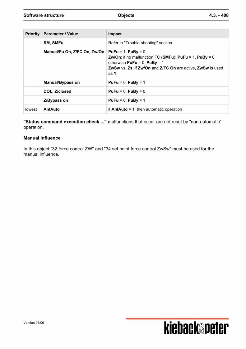
Software structure Objects 4.3. - 408
Priority Parameter / Value Impact
SM, SMFu Refer to "Trouble-shooting" section
Manual/Fu On, Z/FC On, Zw/On PuFu = 1, PuBy = 0Zw/On: if no malfunction FC (SMFu): PuFu = 1, PuBy = 0otherwise PuFu = 0, PuBy = 1ZwSw vs. Zs: if Zw/On and Z/FC On are active, ZwSw is usedas Y
Manual/Bypass on PuFu = 0, PuBy = 1
DOL, Z/closed PuFu = 0, PuBy = 0
Z/Bypass on PuFu = 0, PuBy = 1
lowest AnfAuto if AnfAuto = 1, then automatic operation
"Status command execution check ..." malfunctions that occur are not reset by "non-automatic"operation. Manual influence In this object "32 force control ZW" and "34 set point force control ZwSw" must be used for themanual influence.
Version 05/06
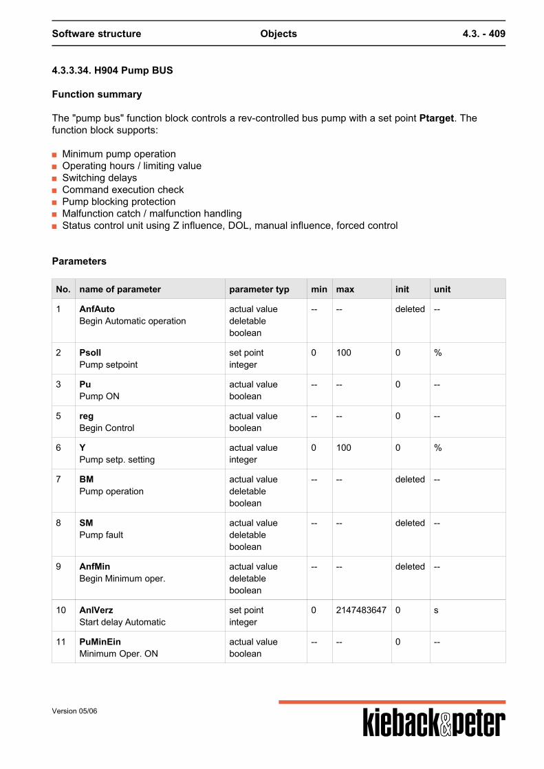
Software structure Objects 4.3. - 409
4.3.3.34. H904 Pump BUS
Function summary
The "pump bus" function block controls a rev-controlled bus pump with a set point Ptarget. Thefunction block supports:
Minimum pump operation Operating hours / limiting value Switching delays Command execution check Pump blocking protection Malfunction catch / malfunction handling Status control unit using Z influence, DOL, manual influence, forced control
Parameters
No. name of parameter parameter typ min max init unit
1 AnfAutoBegin Automatic operation
actual valuedeletableboolean
-- -- deleted --
2 PsollPump setpoint
set pointinteger
0 100 0 %
3 PuPump ON
actual valueboolean
-- -- 0 --
5 regBegin Control
actual valueboolean
-- -- 0 --
6 YPump setp. setting
actual valueinteger
0 100 0 %
7 BMPump operation
actual valuedeletableboolean
-- -- deleted --
8 SMPump fault
actual valuedeletableboolean
-- -- deleted --
9 AnfMinBegin Minimum oper.
actual valuedeletableboolean
-- -- deleted --
10 AnlVerzStart delay Automatic
set pointinteger
0 2147483647 0 s
11 PuMinEinMinimum Oper. ON
actual valueboolean
-- -- 0 --
Version 05/06
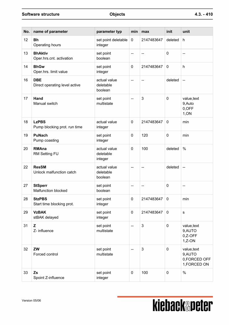
Software structure Objects 4.3. - 410
No. name of parameter parameter typ min max init unit
12 BhOperating hours
set point deletableinteger
0 2147483647 deleted h
13 BhAktivOper.hrs.cnt. activation
set pointboolean
-- -- 0 --
14 BhGwOper.hrs. limit value
set pointinteger
0 2147483647 0 h
16 DBEDirect operating level active
actual valuedeletableboolean
-- -- deleted --
17 HandManual switch
set pointmultistate
-- 3 0 value,text9,Auto0,OFF1,ON
18 LzPBSPump blocking prot. run time
actual valueinteger
0 2147483647 0 min
19 PuNachPump coasting
set pointinteger
0 120 0 min
20 RMAnaRM Setting FU
actual valuedeletableinteger
0 100 deleted %
22 ResSMUnlock malfunction catch
actual valuedeletableboolean
-- -- deleted --
27 StSperrMalfunction blocked
set pointboolean
-- -- 0 --
28 StzPBSStart time blocking prot.
set pointinteger
0 2147483647 0 min
29 VzBAKstBAK delayed
set pointinteger
0 2147483647 0 s
31 ZZ- influence
set pointmultistate
-- 3 0 value,text9,AUTO0,Z-OFF1,Z-ON
32 ZWForced control
set pointmultistate
-- 3 0 value,text9,AUTO0,FORCED OFF1,FORCED ON
33 ZsSpoint Z-influence
set pointinteger
0 100 0 %
Version 05/06
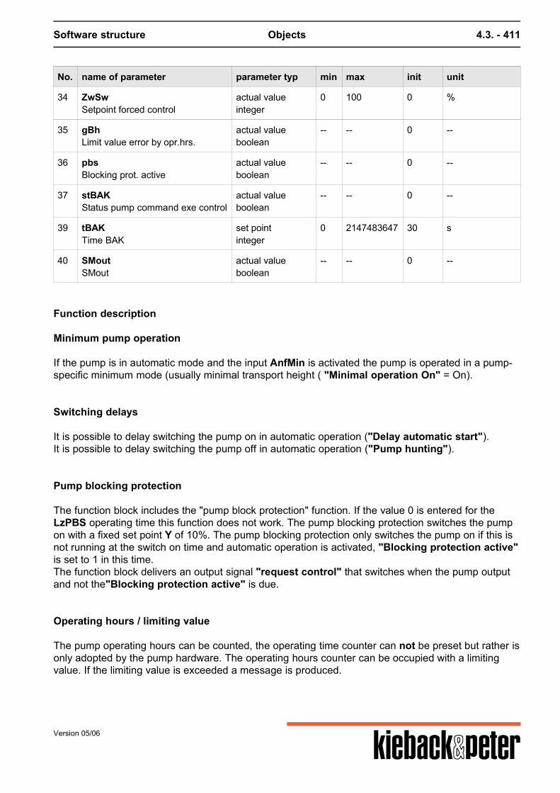
Software structure Objects 4.3. - 411
No. name of parameter parameter typ min max init unit
34 ZwSwSetpoint forced control
actual valueinteger
0 100 0 %
35 gBhLimit value error by opr.hrs.
actual valueboolean
-- -- 0 --
36 pbsBlocking prot. active
actual valueboolean
-- -- 0 --
37 stBAKStatus pump command exe control
actual valueboolean
-- -- 0 --
39 tBAKTime BAK
set pointinteger
0 2147483647 30 s
40 SMoutSMout
actual valueboolean
-- -- 0 --
Function description
Minimum pump operation
If the pump is in automatic mode and the input AnfMin is activated the pump is operated in a pump-specific minimum mode (usually minimal transport height ( "Minimal operation On" = On).
Switching delays
It is possible to delay switching the pump on in automatic operation ("Delay automatic start").It is possible to delay switching the pump off in automatic operation ("Pump hunting").
Pump blocking protection
The function block includes the "pump block protection" function. If the value 0 is entered for theLzPBS operating time this function does not work. The pump blocking protection switches the pumpon with a fixed set point Y of 10%. The pump blocking protection only switches the pump on if this isnot running at the switch on time and automatic operation is activated, "Blocking protection active"is set to 1 in this time.The function block delivers an output signal "request control" that switches when the pump outputand not the"Blocking protection active" is due.
Operating hours / limiting value
The pump operating hours can be counted, the operating time counter can not be preset but rather isonly adopted by the pump hardware. The operating hours counter can be occupied with a limitingvalue. If the limiting value is exceeded a message is produced.
Version 05/06
Software structure Objects 4.3. - 412
Note: The parameter names of the operating hours counter are different from those described in the"Repeating function elements" section.
Command execution check
The function block contains a command execution check (refer to the command execution check fordescription and parameters) for the actual operating status: "Operating message pump", Targetoperating status: "Pump ON", output: "Status command execution check":If the actual operating status is not switched no corresponding command execution checkmalfunction is signaled (stCEC)."Release malfunction catch" resets the command execution check malfunction.Note: The parameter names of the command execution check are different from those described inthe "Repeating function elements" section.
Malfunction catch / malfunction handling
If "unlock malfunction catch" is wired malfunctions that occur are saved and can be reset byactivating the "unlock malfunction catch".An adjoining malfunctionSM or stCEC may influence the control of the "Pump ON" output.a) not ("malfunction blocked" = 0)b) the output "Pump ON" switches to "closed" ("malfunction blocked" = 1)If a malfunction sets the output "Pump ON" to off, this can only be reset by activating the "unlockmalfunction catch".If "unlock malfunction catch" is not wired malfunctions that occur are not saved, i.e. if themalfunction disappears the malfunction handling disappears.
Status control/switch priorities
The following input parameters influence the control of the outputs:AnfAuto, Z(on/off) and Zs, DOL, manual(on/off), Zw(on/off) and ZwSw, SM
Priority Parameter / Value Impact
Highest SM Refer to "Trouble-shooting" section
Zw/Off, Manual/Off Pu = 0
Manual/open, Zw/open Pu = 1
Z/closed, DOL Pu = 0
Z/On Pu = 1
AnfMin if AnfAuto = 1, and AnfMin =1 then Min operation
lowest AnfAuto if AnfAuto = 1, then automatic operation
"Status command execution check ..." malfunctions that occur are not reset by "non-automatic"operation.
Version 05/06
Software structure Objects 4.3. - 413
4.3.3.35. H905 Double pump
Function summary
The "double pump" function block controls a switchable double pump, and supports:
pump switching (varies with operating hours, per switching parameter or for malfunctions) Operating hours / limiting value Switching delays Command execution check Pump blocking protection Malfunction catch / malfunction handling Status control unit using Z influence, DOL, manual influence, repair switch, forced control
Parameters
No. name of parameter parameter typ min max init unit
1 AnfAutoBegin Automatic operation
actual valuedeletableboolean
-- -- deleted --
2 Bh2Oper.hrs. Pump 2
set pointinteger
0 2147483647 0 h
3 Pu1Pump 1 ON
actual valueboolean
-- -- 0 --
4 Pu2Pump 2 ON
actual valueboolean
-- -- 0 --
5 regBegin Control
actual valueboolean
-- -- 0 --
7 BM1Operation msg pump 1
actual valuedeletableboolean
-- -- deleted --
8 SM1Pump 1 fault
actual valuedeletableboolean
-- -- deleted --
9 Rep1Repair switch pump 1
actual valuedeletableboolean
-- -- deleted --
10 AnlVerzStartup delay of the automatic
set pointinteger
0 2147483647 0 s
11 BM2Operation msg pump 2
actual valuedeletableboolean
-- -- deleted --
Version 05/06
Software structure Objects 4.3. - 414
No. name of parameter parameter typ min max init unit
12 Bh1Oper.hrs. Pump 1
set pointinteger
0 2147483647 0 h
13 BhAktivOper.hrs.cnt. activation
set pointboolean
-- -- 0 --
14 BhGw1Oper.hrs. limit value pump 1
set pointinteger
0 2147483647 168 h
15 PuUmPump switching
actual valuedeletableboolean
-- -- deleted --
16 DBEDir. oper. level active
actual valuedeletableboolean
-- -- deleted --
17 HandHand switch AUTO
set pointmultistate
-- 4 0 value,text9,Auto0,OFF1,Pump1_ON2,Pump2_ON
18 LzPBSPump blocking prot. run time
set pointinteger
0 2147483647 0 min
19 PuNachPump coasting
set pointinteger
0 120 0 min
20 BhGw2Oper.hrs. limit value Pump 2
set pointinteger
0 2147483647 168 h
21 ResBh1Reset oper.hrs. pump 1
actual valuedeletableboolean
-- -- deleted --
22 ResSMUnlock Malfunction catch
actual valuedeletableboolean
-- -- deleted --
23 BhGwUPump switch-over limit value
set pointinteger
1 2147483647 72 h
24 Rep2Repair switch pump 2
actual valuedeletableboolean
-- -- deleted --
25 ResBh2Reset oper.hrs. Pump 2
actual valuedeletableboolean
-- -- deleted --
27 StSperrMalfunction blocked
set pointboolean
-- -- 0 --
Version 05/06
Software structure Objects 4.3. - 415
No. name of parameter parameter typ min max init unit
28 StzPBSStart time blocking prot.
set pointinteger
0 2147483647 0 min
29 VzBAKstBAK1 or stBAK2 delayed
set pointinteger
0 2147483647 0 s
30 RzURest time to switch-over
actual valueinteger
0 2147483647 0 min
31 ZZ- influence
set pointmultistate
-- 4 0 value,text9,Auto0,OFF1,Pump1_ON2,Pump2_ON
32 ZwForced control
set pointmultistate
-- 3 0 value,text9,Auto0,OFF1,ON
33 SM2Pump 2 fault
actual valuedeletableboolean
-- -- deleted --
34 UZeitOverlap time
set pointinteger
0 2147483647 0 s
35 gBh1Limit value violation oper. hrs. pump 1
actual valueboolean
-- -- 0 --
36 pbsBlocking prot. active
actual valueboolean
-- -- 0 --
37 stbak1Command exe. control status pump 1
actual valueboolean
-- -- 0 --
38 stbak2Command exe. control status pump 2
actual valueboolean
-- -- 0 --
39 tBAKTime BAK
set pointinteger
0 2147483647 30 s
40 gBh2Limit value violation oper. hrs. pump 2
actual valueboolean
-- -- 0 --
41 SMoutSMout
actual valueboolean
-- -- 0 --
Version 05/06
Software structure Objects 4.3. - 416
Function description
Pump switching
If the input "Pump switching" is not switched operation changes between the two pumps inautomatic mode and for Zw/On depending on the operating hours. For this the pump that is notrunning is activated when the operating time of the currently operating pump exceeds the "limitingvalue pump switching" since the last pump switching. At the same time "Remaining time toswitching" is set to "limiting value pump switching" and starts to count down.If the parameter "Pump switching" is switched, in automatic mode and for Zw/On the relevantpump is activated depending on the value of the parameter, "Pump switching"= 0 -> Pump 1,"Pump switching"= 1 -> Pump 2.The malfunction-dependent pump switching is described in the trouble-shooting section; the input"Pump switching" has no influence on the malfunction-dependent pump switching. Priorities for the various pump switchings Highest prioritymalfunction-dependent pump switchingparameter-dependent pump switchingoperating time-dependent pump switchingLowest priority
Switching delays
It is possible to delay switching the pump on in automatic operation ("Delay automatic start").It is possible to delay switching the pump off in automatic operation ("Pump hunting").
When switching from "Pump 1 On" to "Pump 2 On" or vice versa the pump to beswitched on is activated; the pump to be switched off still operates for the "overlay time"so as to prevent a fall in pressure when building up the pressure in the pump that is to beswitched on.
Pump blocking protection
The function block includes the "pump block protection" function. If the value 0 is enteredfor the LzPBS operating time this function does not work.
The pump blocking protection is only activated when neither of the two pumps is running at the switchon time and automatic mode is activated, "Blocking protection active" is set at this time to 1. Bothpumps are subsequently switched on for a time by "operating time pump blocking protection"; theswitching from pump 1 to pump 2 takes place without an "overlay time".The function block delivers an output signal "request control" that switches when the pump outputsand not the"Blocking protection active" are due.
Version 05/06
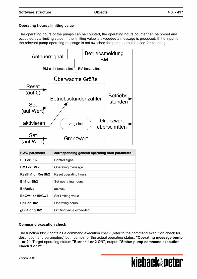
Software structure Objects 4.3. - 417
Operating hours / limiting value
The operating hours of the pumps can be counted, the operating hours counter can be preset andoccupied by a limiting value. If the limiting value is exceeded a message is produced. If the input forthe relevant pump operating message is not switched the pump output is used for counting.
HWO parameter corresponding general operating hour parameter
Pu1 or Pu2 Control signal
BM1 or BM2 Operating message
ResBh1 or ResBh2 Reset operating hours
Bh1 or Bh2 Set operating hours
BhActive activate
BhGw1 or BhGw2 Set limiting value
Bh1 or Bh2 Operating hours
gBh1 or gBh2 Limiting value exceeded
Command execution check
The function block contains a command execution check (refer to the command execution check fordescription and parameters) both pumps for the actual operating status: "Operating message pump1 or 2", Target operating status: "Burner 1 or 2 ON", output: "Status pump command executioncheck 1 or 2".
Version 05/06
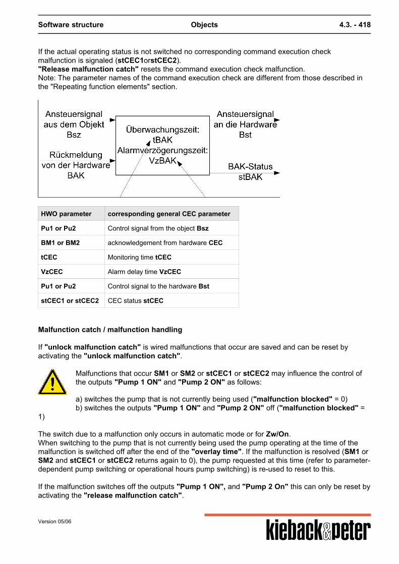
Software structure Objects 4.3. - 418
If the actual operating status is not switched no corresponding command execution checkmalfunction is signaled (stCEC1orstCEC2)."Release malfunction catch" resets the command execution check malfunction.Note: The parameter names of the command execution check are different from those described inthe "Repeating function elements" section.
HWO parameter corresponding general CEC parameter
Pu1 or Pu2 Control signal from the object Bsz
BM1 or BM2 acknowledgement from hardware CEC
tCEC Monitoring time tCEC
VzCEC Alarm delay time VzCEC
Pu1 or Pu2 Control signal to the hardware Bst
stCEC1 or stCEC2 CEC status stCEC
Malfunction catch / malfunction handling
If "unlock malfunction catch" is wired malfunctions that occur are saved and can be reset byactivating the "unlock malfunction catch".
Malfunctions that occur SM1 or SM2 or stCEC1 or stCEC2 may influence the control ofthe outputs "Pump 1 ON" and "Pump 2 ON" as follows:
a) switches the pump that is not currently being used ("malfunction blocked" = 0)b) switches the outputs "Pump 1 ON" and "Pump 2 ON" off ("malfunction blocked" =
1)
The switch due to a malfunction only occurs in automatic mode or for Zw/On.When switching to the pump that is not currently being used the pump operating at the time of themalfunction is switched off after the end of the "overlay time". If the malfunction is resolved (SM1 orSM2 and stCEC1 or stCEC2 returns again to 0), the pump requested at this time (refer to parameter-dependent pump switching or operational hours pump switching) is re-used to reset to this. If the malfunction switches off the outputs "Pump 1 ON", and "Pump 2 On" this can only be reset byactivating the "release malfunction catch".
Version 05/06
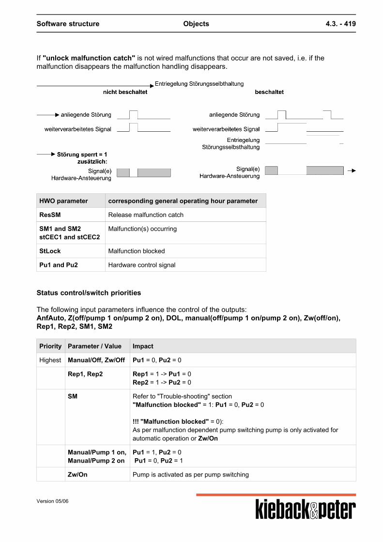
Software structure Objects 4.3. - 419
If "unlock malfunction catch" is not wired malfunctions that occur are not saved, i.e. if themalfunction disappears the malfunction handling disappears.
HWO parameter corresponding general operating hour parameter
ResSM Release malfunction catch
SM1 and SM2stCEC1 and stCEC2
Malfunction(s) occurring
StLock Malfunction blocked
Pu1 and Pu2 Hardware control signal
Status control/switch priorities
The following input parameters influence the control of the outputs:AnfAuto, Z(off/pump 1 on/pump 2 on), DOL, manual(off/pump 1 on/pump 2 on), Zw(off/on),Rep1, Rep2, SM1, SM2
Priority Parameter / Value Impact
Highest Manual/Off, Zw/Off Pu1 = 0, Pu2 = 0
Rep1, Rep2 Rep1 = 1 -> Pu1 = 0Rep2 = 1 -> Pu2 = 0
SM Refer to "Trouble-shooting" section"Malfunction blocked" = 1: Pu1 = 0, Pu2 = 0 !!! "Malfunction blocked" = 0):As per malfunction dependent pump switching pump is only activated forautomatic operation or Zw/On
Manual/Pump 1 on,Manual/Pump 2 on
Pu1 = 1, Pu2 = 0 Pu1 = 0, Pu2 = 1
Zw/On Pump is activated as per pump switching
Version 05/06

Software structure Objects 4.3. - 420
Priority Parameter / Value Impact
Z/closed, DOL Pu1 = 0, Pu2 = 0
Z/Pump 1 on,Z/Pump 2 on
Pu1 = 1, Pu2 = 0 Pu1 = 0, Pu2 = 1
lowest AnfAuto if AnfAuto = 1, then automatic operation
"Status command execution check ..." malfunctions that occur are not reset by "non-automatic"operation.
Version 05/06
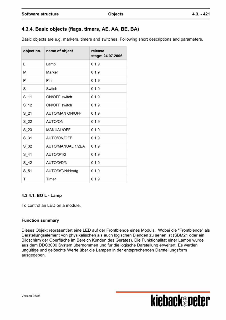
Software structure Objects 4.3. - 421
4.3.4. Basic objects (flags, timers, AE, AA, BE, BA)
Basic objects are e.g. markers, timers and switches. Following short descriptions and parameters.
object no. name of object releasestage: 24.07.2006
L Lamp 0.1.9
M Marker 0.1.9
P Pin 0.1.9
S Switch 0.1.9
S_11 ON/OFF switch 0.1.9
S_12 ON/OFF switch 0.1.9
S_21 AUTO/MAN ON/OFF 0.1.9
S_22 AUTO/ON 0.1.9
S_23 MANUAL/OFF 0.1.9
S_31 AUTO/ON/OFF 0.1.9
S_32 AUTO/MANUAL 1/2EA 0.1.9
S_41 AUTO/0/1/2 0.1.9
S_42 AUTO/0/D/N 0.1.9
S_51 AUTO/0/T/N/Heatg 0.1.9
T Timer 0.1.9
4.3.4.1. BO L - Lamp
To control an LED on a module.
Function summary
Dieses Objekt repräsentiert eine LED auf der Frontblende eines Moduls. Wobei die "Frontblende" alsDarstellungselement von physikalischen als auch logischen Blenden zu sehen ist (SBM21 oder einBildschirm der Oberfläche im Bereich Kunden des Gerätes). Die Funktionalität einer Lampe wurdeaus dem DDC3000 System übernommen und für die logische Darstellung erweitert. Es werdenungültige und gelöschte Werte über die Lampen in der entsprechenden Darstellungsformausgegeben.
Version 05/06
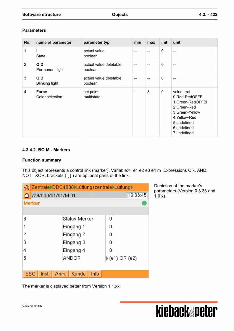
Software structure Objects 4.3. - 422
Parameters
No. name of parameter parameter typ min max init unit
1 lState
actual valueboolean
-- -- 0 --
2 Q DPermanent light
actual value deletableboolean
-- -- 0 --
3 Q BBlinking light
actual value deletableboolean
-- -- 0 --
4 FarbeColor selection
set pointmultistate
-- 8 0 value,text0,Red-RedOFFBl1,Green-RedOFFBl2,Green-Red3,Green-Yellow4,Yellow-Red5,undefined6,undefined7,undefined
4.3.4.2. BO M - Markers
Function summary
This object represents a control link (marker). Variable:= e1 e2 e3 e4 m Expressions OR, AND,NOT, XOR, brackets ( [ ] ) are optional parts of the link.
Depiction of the marker'sparameters (Version 0.3.33 and1.0.x)
The marker is displayed better from Version 1.1.xx.
Version 05/06
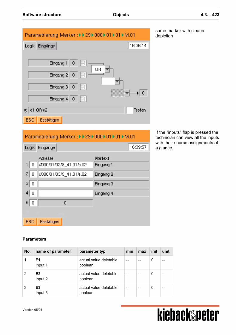
Software structure Objects 4.3. - 423
same marker with clearerdepiction
If the "inputs" flap is pressed thetechnician can view all the inputswith their source assignments ata glance.
Parameters
No. name of parameter parameter typ min max init unit
1 E1Input 1
actual value deletableboolean
-- -- 0 --
2 E2Input 2
actual value deletableboolean
-- -- 0 --
3 E3Input 3
actual value deletableboolean
-- -- 0 --
Version 05/06
Software structure Objects 4.3. - 424
No. name of parameter parameter typ min max init unit
4 E4Input 4
actual value deletableboolean
-- -- 0 --
5 VVector
set pointtext
-- -- --
6 mStatus marker
actual valueboolean
-- -- 0 --
4.3.4.3. BO P - Pin
Function summary
Das Pin-Objekt steht für eine I/O-Klemme. Über den Parameter, der hinter Par_Config steht, wird einSubobjekt installiert. Je nach Subobjekt werden genau die Möglichkeiten eines analogen Einganges,eines analogen Ausganges, eines binären Einganges oder eines binären Ausganges angeboten.Welche Funktionen möglich sind, hängt vom übergeordneten Modul-Objekt ab, das die Möglichkeitendes betreuten Busmoduls (oder der IO-Karte) kennt. Es sorgt dafür, dass die Auswahl-Möglichkeitenbezüglich der Subobjekte eingeschränkt werden. Der Parameter hinter Par_Config bestimmt,welches Subobjekt angehängt wird: 0 = kein Subobjekt = keine Funktion 1 = CDI = Binärer Eingang 2= CDO = Binärer Ausgang 3 = CAI = Analoger Eingang 4 = CAO = Analoger Ausgang.
The function of a PINS is stipulated by attaching a sub-object e.g. CAI for analog input. For this depending on the hardware of the PIN it is possible to select several sub-objects. For example, a PIN can be an output that can then be read back.
Parameters
No. name of parameter parameter typ min max init unit
1 TypPin type selection
set pointmultistate
-- 5 0 value,text0,no function1,Binary input2,Binary output3,Analog input4,Analog output
2 ANPin type selection
set pointmultistate
-- 3 0 value,text0,no function3,Analog input4,Analog output
3 AIPin type selection
set pointmultistate
-- 2 0 value,text0,no function3,Analog input
Version 05/06
Software structure Objects 4.3. - 425
No. name of parameter parameter typ min max init unit
4 AOPin type selection
set pointmultistate
-- 2 0 value,text0,no function4,Analog output
5 DNPin type selection
set pointmultistate
-- 3 0 value,text0,no function1,Binary input2,Binary output
6 DIPin type selection
set pointmultistate
-- 2 0 value,text0,no function1,Binary input
7 DOPin type selection
set pointmultistate
-- 2 0 value,text0,no function2,Binary output
8 KnPin connection
set point deletabletext
-- -- deleted --
Version 05/06
Software structure Objects 4.3. - 426
4.3.4.4. BO S - Switches
Function summary
Is there for the sake of completeness. This switch aims to integrate the switches of the SBM into theDDC4000 system.
Jede der Tasten auf den Modulen kann als Taster (T), Schalter (S) oder als Teil einer Schaltergruppemit gegenseitiger Auslösung definiert werden.Schaltergruppen bestehen aus mindestens 2 aufeinanderfolgenden Schaltern. Die Schaltergruppenwerden der Reihe nach durchnummeriert. Nach Anwahl des entsprechenden Parameters lassen sichdie Tasten in ihrer Funktion festlegen.
Parameters
No. name of parameter parameter typ min max init unit
1 TypeType
set pointmultistate
-- 18 0 value,text0,Push-button switch1,Switch2,Group_13,Group_24,Group_35,Group_46,Group_57,Group_68,Group_79,Group_810,Group_911,Group_1012,Group_1113,Group_1214,Group_1315,Group_1416,Group_1517,Group_16
2 sSwitch Status
set point deletableboolean
-- -- deleted --
4.3.4.5. BO S_11 - Switch single stage ON/OFF
Function summary
Ein einstufiger Schalter mit dem Text EIN/AUS - Eltako-Funktion (rastender Taster).
Version 05/06
Software structure Objects 4.3. - 427
Parameters
No. name of parameter parameter typ min max init unit
h handSwitch Status
actual valuemultistate
-- 2 0 value,text0,MANUAL OFF1,MANUAL ON
s.01 s.01ON/OFF
set pointboolean
-- -- 0 --
4.3.4.6. BO S_12 - Confirmation switch
Function summary
A sensor with confirmation function. Resets to 0 after 1 second.
Parameters
No. name of parameter parameter typ min max init unit
h handSwitch Status
actual valuemultistate
-- 2 0 value,text0,OFF1,Receipt
s.01 s.01Receipt
set pointboolean
-- -- 0 --
4.3.4.7. BO S_21 - 2 push-button MANUAL/AUTO, ON/OFF
Function summary
Dieser Schalter hat die Funktion, mit dem ersten Knopf Auto/Hand und mit dem zweiten KnopfEin/Aus zu schalten.
Version 05/06
Software structure Objects 4.3. - 428
Parameters
No. name of parameter parameter typ min max init unit
h handSwitch Status
actual valuemultistate
-- 3 2 value,text9,AUTO1,Manual ON0,Manual OFF
s.01 s.01AUTO/Manual
set pointboolean
-- -- 0 --
s.02 s.02OFF/ON
set pointboolean
-- -- 0 --
4.3.4.8. BO S_22 2 push-buttons AUTO, Manual On
Function summary
Eine Schaltergruppe mit 2 Schaltern:
Zustand Taste 1 AUTO Zustand Taste 2 EIN
Parameters
No. name of parameter parameter typ min max init unit
h handSwitch Status
actual valuemultistate
-- 2 0 value,text9,AUTO1,ON
s.01 s.01AUTO
set pointboolean
-- -- 1 --
s.02 s.02MANUAL ON
set pointboolean
-- -- 0 --
4.3.4.9. BO S_23 (as 22)
Function summary
Eine Schaltergruppe mit 2 Schaltern:
Zustand Taste 1 AUTO Zustand Taste 2 AUS
Version 05/06
Software structure Objects 4.3. - 429
Parameters
No. name of parameter parameter typ min max init unit
h handSwitch Status
actual valuemultistate
-- 2 0 value,text0,MANUAL OFF9,AUTO
s.01 s.01AUTO
set pointboolean
-- -- 0 --
s.02 s.02Manual OFF
set pointboolean
-- -- 1 --
4.3.4.10. BO S_31 - 3 push-buttons AUTO, Manual off, Manual on
Function summary
Eine Schaltergruppe mit 3 Schaltern:
Zustand Taste 1 AUTO Zustand Taste 2 HAND AUS Zustand Taste 3 HAND EIN
Parameters
No. name of parameter parameter typ min max init unit
h handSwitch Status
actual valuemultistate
-- 3 0 value,text9,AUTO0,MANUAL OFF1,MANUAL ON
s.01 s.01AUTO
set pointboolean
-- -- 1 --
s.02 s.02MANUAL OFF
set pointboolean
-- -- 0 --
s.03 s.03MANUAL ON
set pointboolean
-- -- 0 --
4.3.4.11. BO S_32 - 3 push-buttons AUTO/manual, Level1 ON/OFF, Level 2 ON/OFF
Function summary
Eine Schaltergruppe mit 3 Schaltern:
Zustand Taste 1 AUTO/HAND Zustand Taste 2 STUFE1 EIN/AUS
Version 05/06
Software structure Objects 4.3. - 430
Zustand Taste 3 STUFE2 EIN/AUS
Parameters
No. name of parameter parameter typ min max init unit
h handSwitch Status
actual valuemultistate
-- 4 1 value,text9,AUTO/MANUAL0,OFF1,MANUAL ON LEV 12,MANUAL ON LEV 2
s.01 s.01AUTO/MANUAL
actual valueboolean
-- -- 0 --
s.02 s.02MANUAL LEV 1
actual valueboolean
-- -- 0 --
s.03 s.03MANUAL LEV 2
actual valueboolean
-- -- 0 --
4.3.4.12. BO S_41 - 4 Push-buttons AUTO, OFF, Manual Level 1, Level 2
Function summary
Eine Schaltergruppe mit 4 Schaltern:
Zustand Taste 1 AUTO Zustand Taste 2 AUS Zustand Taste 3 HAND STUFE 1 Zustand Taste 4 HAND STUFE 2
Parameters
No. name of parameter parameter typ min max init unit
h handSwitch Status
actual valuemultistate
-- 4 0 value,text9,AUTO0,OFF1,MANUAL ON LEV 12,MANUAL ON LEV 2
s.01 s.01AUTO
set pointboolean
-- -- 1 --
s.02 s.02OFF
set pointboolean
-- -- 0 --
s.03 s.03MANUAL ON LEV 1
set pointboolean
-- -- 0 --
Version 05/06
Software structure Objects 4.3. - 431
No. name of parameter parameter typ min max init unit
s.04 s.04MANUAL ON LEV 2
set pointboolean
-- -- 0 --
4.3.4.13. BO S_42 - 4 Push-buttons AUTO, DAY, NIGHT, OFF
Function summary
Eine Schaltergruppe mit 4 Schaltern:
Zustand Taste 1 AUTO Zustand Taste 2 Fern Tag Zustand Taste 3 Fern Nacht Zustand Taste 4 Fern Aus
Parameters
No. name of parameter parameter typ min max init unit
h handSwitch Status
actual valuemultistate
-- 4 0 value,text9,Remote Auto0,Remote OFF1,Remote Day35,Remote Night
s.01 s.01AUTO
set pointboolean
-- -- 1 --
s.02 s.02DAY
set pointboolean
-- -- 0 --
s.03 s.03NIGHT
set pointboolean
-- -- 0 --
s.04 s.04OFF
set pointboolean
-- -- 0 --
4.3.4.14. BO S_51 - 5 Push-buttons Auto, off, Manual Level 1, 2, 3
Function summary
Eine Schaltergruppe mit 5 Schaltern:
Zustand Taste 1 AUTO Zustand Taste 2 AUF Zustand Taste 3 TAG Zustand Taste 4 NACHT Zustand Taste 5 Aufheizen
Version 05/06
Software structure Objects 4.3. - 432
Parameters
No. name of parameter parameter typ min max init unit
h handSwitch Status
actual valuemultistate
-- 5 0 value,text9,Z AUTO0,Z-OFF1,Z DAY35,Z NIGHT36,Z Heating
s.01 s.01AUTO
set pointboolean
-- -- 1 --
s.02 s.02OFF
set pointboolean
-- -- 0 --
s.03 s.03DAY
set pointboolean
-- -- 0 --
s.04 s.04NIGHT
set pointboolean
-- -- 0 --
s.05 s.05HEATING
set pointboolean
-- -- 0 --
4.3.4.15. BO T - Timer
Function summary
Die Timer können von 1 Sekude bis 35999 Sekunden (99:59:59) jeweils Einschalt- und/oderAusschaltverzögert eingestellt werden.Die Startzeit wird in Parameter Tstart SzT angezeigt. Timer können während ihrer Laufzeit durch eineerneute Triggerung (auf 0 gesetzt und) neu gestartet werden.
Parameters
No. name of parameter parameter typ min max init unit
e EInput
actual value deletableboolean
-- -- 0 --
f ff
set pointmultistate
-- 3 0 value,text0,Timer1,Switch-on impulse2,On/Off switch impulse
reset ResTReset Timer
set pointboolean
-- -- 0 --
t tStatus Timer
actual valueboolean
-- -- 0 --
Version 05/06
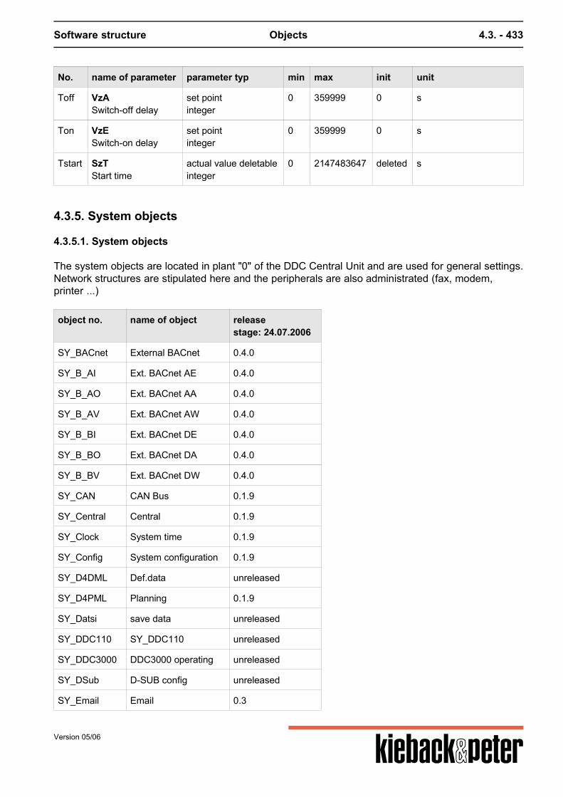
Software structure Objects 4.3. - 433
No. name of parameter parameter typ min max init unit
Toff VzASwitch-off delay
set pointinteger
0 359999 0 s
Ton VzESwitch-on delay
set pointinteger
0 359999 0 s
Tstart SzTStart time
actual value deletableinteger
0 2147483647 deleted s
4.3.5. System objects
4.3.5.1. System objects
The system objects are located in plant "0" of the DDC Central Unit and are used for general settings.Network structures are stipulated here and the peripherals are also administrated (fax, modem,printer ...)
object no. name of object releasestage: 24.07.2006
SY_BACnet External BACnet 0.4.0
SY_B_AI Ext. BACnet AE 0.4.0
SY_B_AO Ext. BACnet AA 0.4.0
SY_B_AV Ext. BACnet AW 0.4.0
SY_B_BI Ext. BACnet DE 0.4.0
SY_B_BO Ext. BACnet DA 0.4.0
SY_B_BV Ext. BACnet DW 0.4.0
SY_CAN CAN Bus 0.1.9
SY_Central Central 0.1.9
SY_Clock System time 0.1.9
SY_Config System configuration 0.1.9
SY_D4DML Def.data unreleased
SY_D4PML Planning 0.1.9
SY_Datsi save data unreleased
SY_DDC110 SY_DDC110 unreleased
SY_DDC3000 DDC3000 operating unreleased
SY_DSub D-SUB config unreleased
SY_Email Email 0.3
Version 05/06
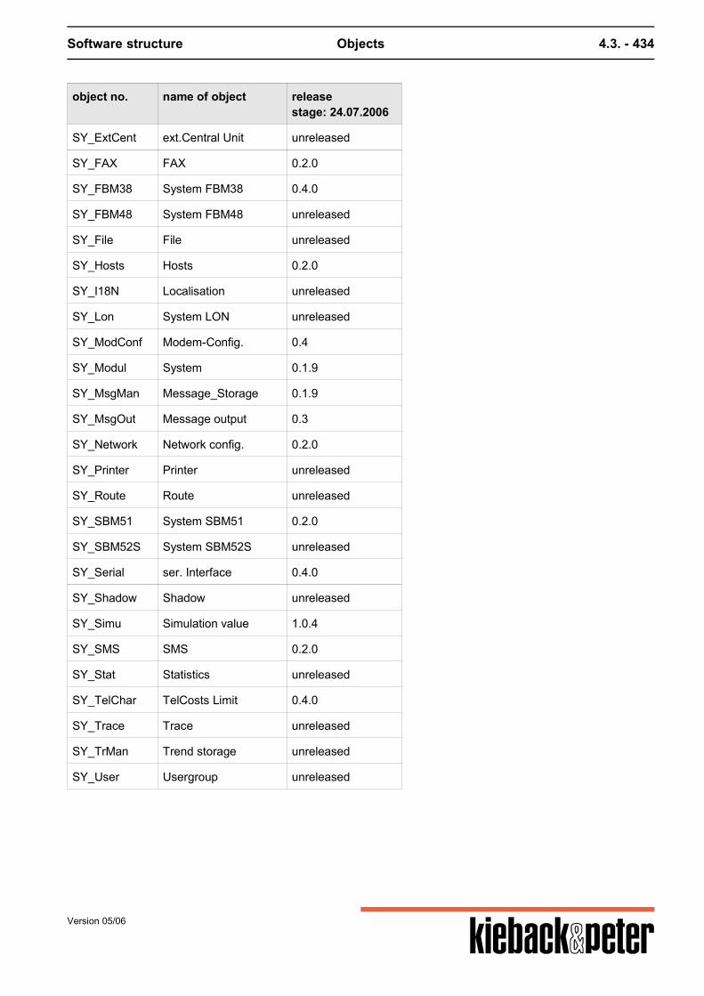
Software structure Objects 4.3. - 434
object no. name of object releasestage: 24.07.2006
SY_ExtCent ext.Central Unit unreleased
SY_FAX FAX 0.2.0
SY_FBM38 System FBM38 0.4.0
SY_FBM48 System FBM48 unreleased
SY_File File unreleased
SY_Hosts Hosts 0.2.0
SY_I18N Localisation unreleased
SY_Lon System LON unreleased
SY_ModConf Modem-Config. 0.4
SY_Modul System 0.1.9
SY_MsgMan Message_Storage 0.1.9
SY_MsgOut Message output 0.3
SY_Network Network config. 0.2.0
SY_Printer Printer unreleased
SY_Route Route unreleased
SY_SBM51 System SBM51 0.2.0
SY_SBM52S System SBM52S unreleased
SY_Serial ser. Interface 0.4.0
SY_Shadow Shadow unreleased
SY_Simu Simulation value 1.0.4
SY_SMS SMS 0.2.0
SY_Stat Statistics unreleased
SY_TelChar TelCosts Limit 0.4.0
SY_Trace Trace unreleased
SY_TrMan Trend storage unreleased
SY_User Usergroup unreleased
Version 05/06
Software structure Objects 4.3. - 435
4.3.5.2. SY_Module Module settings general
Function summary
This system object contains the setting parameters above all that are important for each DDC CentralUnit (BMR) and also bus modules (IO cards). This includes in particular the software version number in parameter 899 and the Bacnet device ID.
Parameters
No. name of parameter parameter typ min max init unit
899 Prog. Version actual valuetext
-- -- Revision: Head --
AnmCount LogonCounter actual valueinteger
-2147483648 2147483647 0 --
BACPrio BACnet-Prio. set pointinteger
1 16 9 --
DevId BACnet DeviceId set pointinteger
0 4194303 0 --
DubAdr Address double actual valueboolean
-- -- 0 --
ErrNo Fault Code actual valueinteger
0 2147483647 0 --
Error Fault module actual valueboolean
-- -- 0 --
Version 05/06
Software structure Objects 4.3. - 436
No. name of parameter parameter typ min max init unit
HwRev HardwareVersion actual valuetext
-- -- -.- --
SetFree Send release set pointboolean
-- -- 1 --
State State actual valuemultistate
-- 3 2 value,text0,passive1,active99,virtual
BACPrio: The parameter describes the priority used to change a DDC parameter. The following peculiarity is important: If parameters are changed via the DDC interface, priority 9 applies to it for example. Then it is stipulated that the DDC should be given priority 10. If the BACPrio parameter is now set to10 all the values changed in the DDC are moved to priority 10. Warning! This may mean that superordinate setting commands etc. take sudden effect if their priorityis now larger.
4.3.5.3. SY_Config plant configuration
Function summary
DDC central parameters can be viewed (internal temp) and set in this object. The most important parameter here is the central unit address. Many program process are based onthis address so if it is changed a cold start is required.
Version 05/06
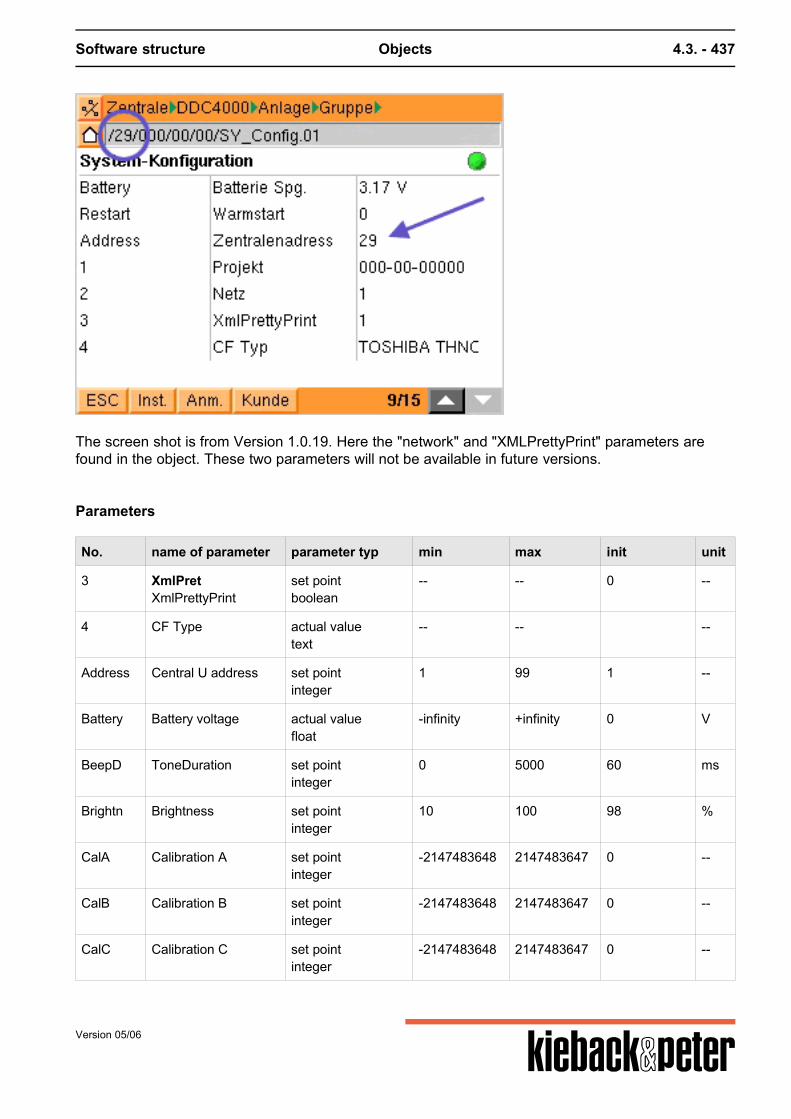
Software structure Objects 4.3. - 437
The screen shot is from Version 1.0.19. Here the "network" and "XMLPrettyPrint" parameters arefound in the object. These two parameters will not be available in future versions.
Parameters
No. name of parameter parameter typ min max init unit
3 XmlPretXmlPrettyPrint
set pointboolean
-- -- 0 --
4 CF Type actual valuetext
-- -- --
Address Central U address set pointinteger
1 99 1 --
Battery Battery voltage actual valuefloat
-infinity +infinity 0 V
BeepD ToneDuration set pointinteger
0 5000 60 ms
Brightn Brightness set pointinteger
10 100 98 %
CalA Calibration A set pointinteger
-2147483648 2147483647 0 --
CalB Calibration B set pointinteger
-2147483648 2147483647 0 --
CalC Calibration C set pointinteger
-2147483648 2147483647 0 --
Version 05/06
Software structure Objects 4.3. - 438
No. name of parameter parameter typ min max init unit
CalD Calibration D set pointinteger
-2147483648 2147483647 0 --
CalE Calibration E set pointinteger
-2147483648 2147483647 0 --
CalF Calibration F set pointinteger
-2147483648 2147483647 0 --
CalS Calibration S set pointinteger
-2147483648 2147483647 0 --
dbg0 Internal set pointtext
-- -- --
Hostnam Host name actual valuetext
-- -- DDC4000.01 --
Logserv Logserver set point deletabletext
-- -- deleted --
Restart Warm start set pointboolean
-- -- 0 --
Temp Inside temperature actual valuefloat
-infinity +infinity 0 C
Voltage Backup Voltage actual valuefloat
0 5 0 V
4.3.5.4. SY_CAN CAN bus
Function summary
This object is used to configure the CAN busses.
Version 05/06
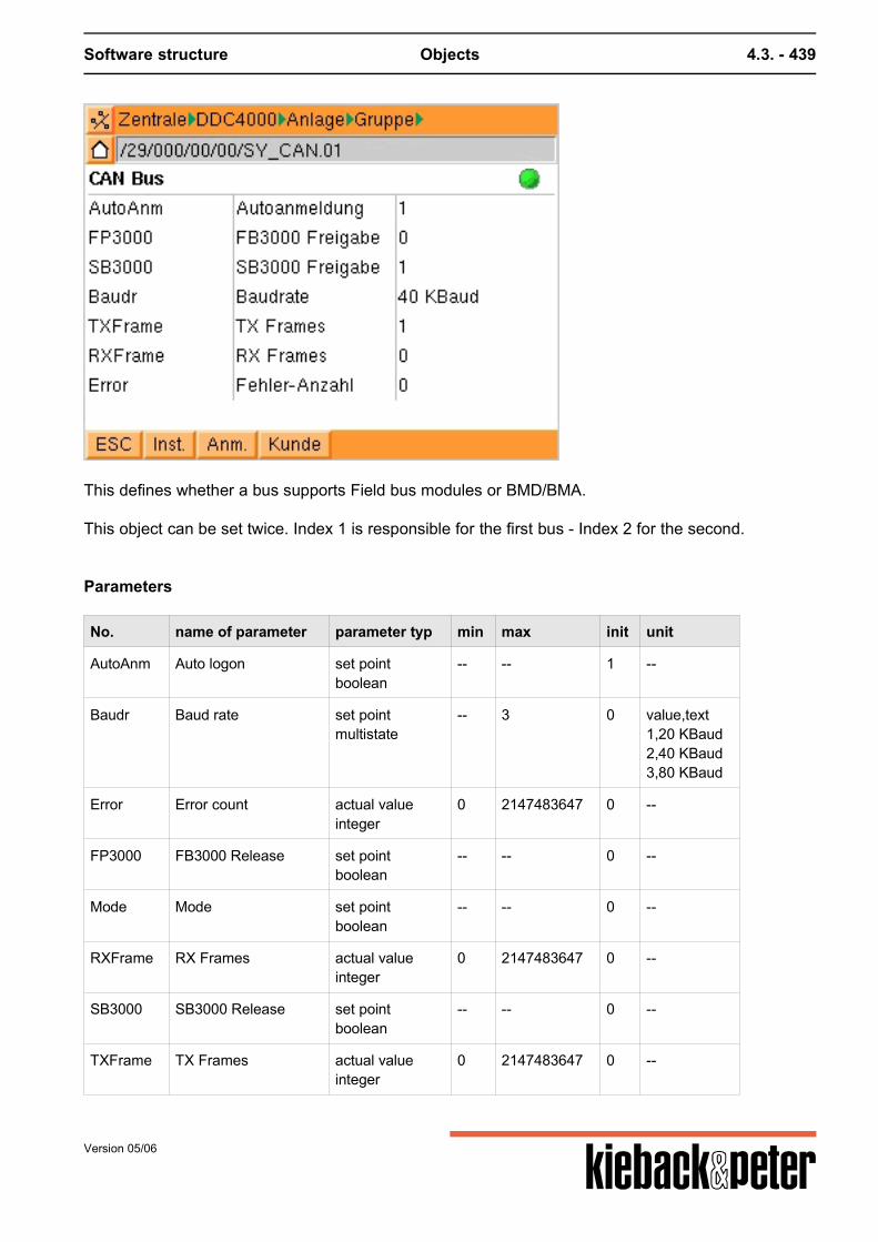
Software structure Objects 4.3. - 439
This defines whether a bus supports Field bus modules or BMD/BMA. This object can be set twice. Index 1 is responsible for the first bus - Index 2 for the second.
Parameters
No. name of parameter parameter typ min max init unit
AutoAnm Auto logon set pointboolean
-- -- 1 --
Baudr Baud rate set pointmultistate
-- 3 0 value,text1,20 KBaud2,40 KBaud3,80 KBaud
Error Error count actual valueinteger
0 2147483647 0 --
FP3000 FB3000 Release set pointboolean
-- -- 0 --
Mode Mode set pointboolean
-- -- 0 --
RXFrame RX Frames actual valueinteger
0 2147483647 0 --
SB3000 SB3000 Release set pointboolean
-- -- 0 --
TXFrame TX Frames actual valueinteger
0 2147483647 0 --
Version 05/06
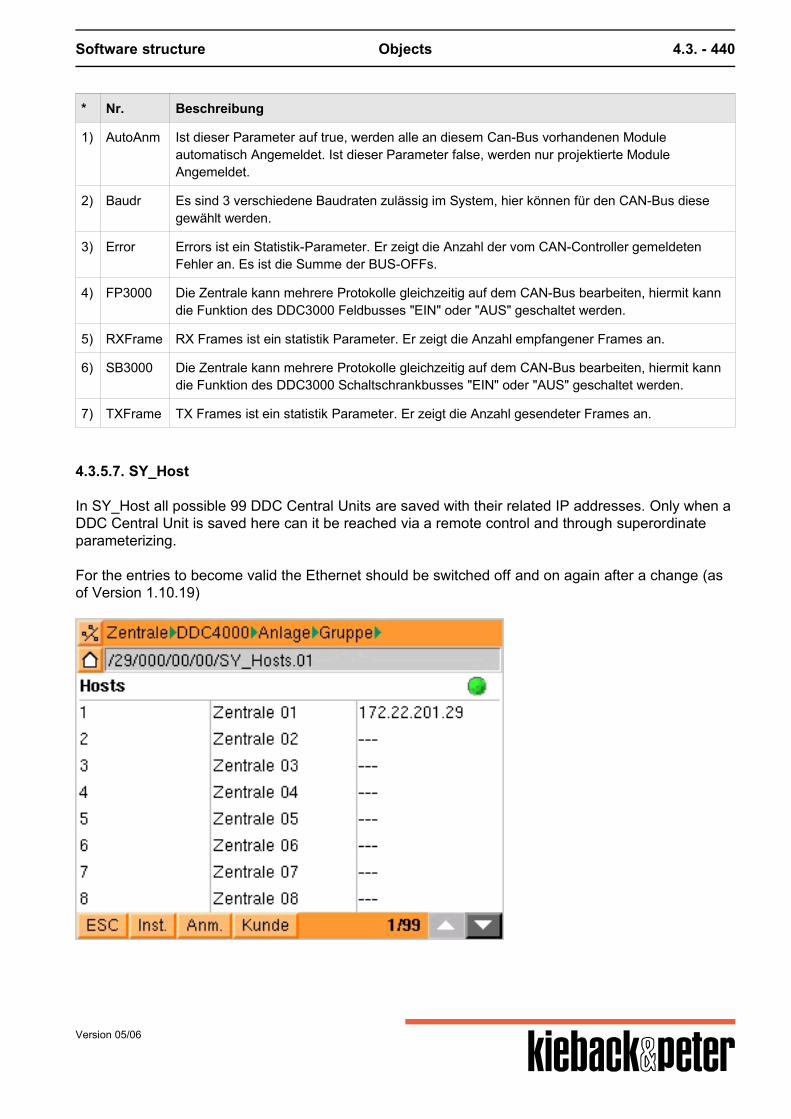
Software structure Objects 4.3. - 440
* Nr. Beschreibung
1) AutoAnm Ist dieser Parameter auf true, werden alle an diesem Can-Bus vorhandenen Moduleautomatisch Angemeldet. Ist dieser Parameter false, werden nur projektierte ModuleAngemeldet.
2) Baudr Es sind 3 verschiedene Baudraten zulässig im System, hier können für den CAN-Bus diesegewählt werden.
3) Error Errors ist ein Statistik-Parameter. Er zeigt die Anzahl der vom CAN-Controller gemeldetenFehler an. Es ist die Summe der BUS-OFFs.
4) FP3000 Die Zentrale kann mehrere Protokolle gleichzeitig auf dem CAN-Bus bearbeiten, hiermit kanndie Funktion des DDC3000 Feldbusses "EIN" oder "AUS" geschaltet werden.
5) RXFrame RX Frames ist ein statistik Parameter. Er zeigt die Anzahl empfangener Frames an.
6) SB3000 Die Zentrale kann mehrere Protokolle gleichzeitig auf dem CAN-Bus bearbeiten, hiermit kanndie Funktion des DDC3000 Schaltschrankbusses "EIN" oder "AUS" geschaltet werden.
7) TXFrame TX Frames ist ein statistik Parameter. Er zeigt die Anzahl gesendeter Frames an.
4.3.5.7. SY_Host
In SY_Host all possible 99 DDC Central Units are saved with their related IP addresses. Only when aDDC Central Unit is saved here can it be reached via a remote control and through superordinateparameterizing. For the entries to become valid the Ethernet should be switched off and on again after a change (asof Version 1.10.19)
Version 05/06
Software structure Objects 4.3. - 441
4.3.5.8. SY_FAX
The fax system object is used to stipulate the fax numbers that are to be dialed via a message.
The corresponding fax number is used via the output definition (SY_MsgOut) relating to themessage.
For this please observe a special binary coding. Refer to SY_MsgOut.
Version 05/06
Software structure Objects 4.3. - 442
4.3.5.9. SY_MsgMan
This system object is to be used for setting up the message memory. With the aid of the possiblesettings here the size of the memory can be stipulated and the messages deleted.
Via "Quit MS" you can confirm messages that have accumulated. Entry must be set briefly to 1. Via "Delete MS " you can delete all message pairs (malfunction and normal messages). Entry mustbe set briefly to 1. A small trick for deleting the memory: set memory size to 1 - then the memory only holds 1 message.Mark this with a normal message and delete. A new value message can be connected via "new message".
4.3.5.10. SY_EMAIL
As in SY_FAX you can stipulate addresses for the output here. Under "name" there should be a username for simpler identification.
Version 05/06
Software structure Objects 4.3. - 443
The SMTP address is set in SY_ModConf. (Version 1.0.19)
Up to version 1.2 there will only be the option of sending a mail within an intranet. The Internet dialingprocedure and the required authentification algorithms have not been implemented yet.
4.3.5.11. Sy_Clock
In Sy_Clock (plant time) you can enter the time zone and current time.By entering the time zone you define whether the clock is altered for summer/winter time.
Version 05/06
Software structure Objects 4.3. - 444
Entering the date
4.3.5.12. SY_Serial
SY_Serial (Modem operation)
Go to "ser. interf.".In the "mode" parameter enter a "3" for RS232 modem. (1 means inactive).Or from Version 1.1.X select "RS232 modem".
Version 05/06
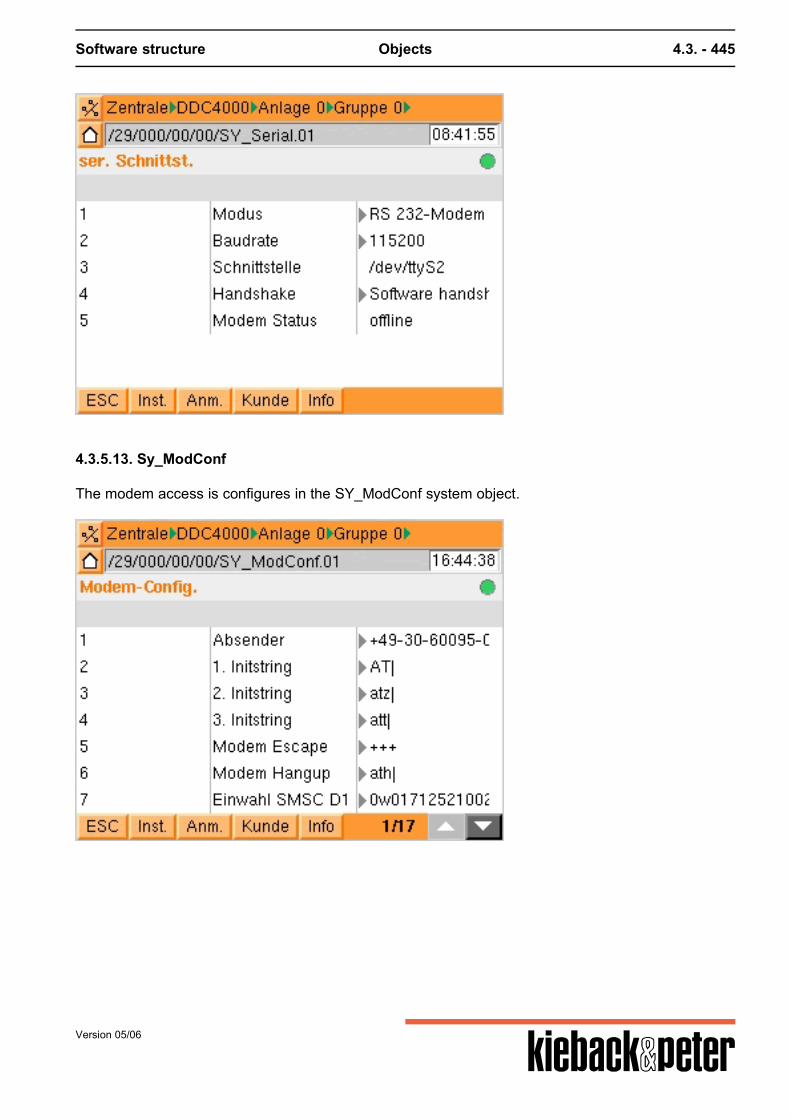
Software structure Objects 4.3. - 445
4.3.5.13. Sy_ModConf
The modem access is configures in the SY_ModConf system object.
Version 05/06
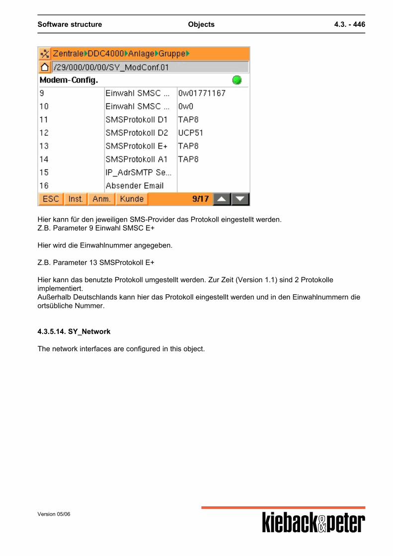
Software structure Objects 4.3. - 446
Hier kann für den jeweiligen SMS-Provider das Protokoll eingestellt werden.Z.B. Parameter 9 Einwahl SMSC E+
Hier wird die Einwahlnummer angegeben.
Z.B. Parameter 13 SMSProtokoll E+
Hier kann das benutzte Protokoll umgestellt werden. Zur Zeit (Version 1.1) sind 2 Protokolleimplementiert.Außerhalb Deutschlands kann hier das Protokoll eingestellt werden und in den Einwahlnummern dieortsübliche Nummer.
4.3.5.14. SY_Network
The network interfaces are configured in this object.
Version 05/06
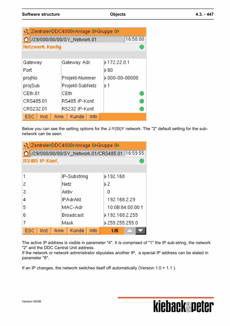
Software structure Objects 4.3. - 447
Below you can see the setting options for the J-Y(St)Y network. The "2" default setting for the sub-network can be seen.
The active IP address is visible in parameter "4". It is comprised of "1" the IP sub-string, the network"2" and the DDC Central Unit address.If the network or network administrator stipulates another IP, a special IP address can be stated inparameter "8". If an IP changes, the network switches itself off automatically (Version 1.0 + 1.1 ).
Version 05/06
Software structure Objects 4.3. - 448
4.3.6. Attachment functions
Function objects
To expand (influence) parameters function objects (F_**) etc. are used. This should for exampleenable a parameter to be scaled without losing the reference to an output parameter.
object no. name of object releasestage: 24.07.2006
F001 Polynomial 0.1.43
F002 Operating hours 0.1.9
F003 Input limit 0.4.0
F004 Self holding 0.4.0
F005 Command execution check 0.4.0
F006 Damping 0.2.0
F007 Delay 0.2.0
F008 Limit value monitoring 0.1.9
F009 Blocking protection 0.2.0
F010 Block prot. st. 0.2.0
F011 Z-contact unreleased
F012 Scaling unreleased
F013 Simulation 1.0.4
F014 Inverting 0.3.33
F015 Counter unreleased
F016 Replace value unreleased
F017 Object status 0.1.9
F019 Adjustment 0.4.0
FAIMO Sensor over 0.2.0
FB_AI BACnet Analog-Input 0.2.0
FB_AO BACnet AA 0.2.0
FB_AV BACnet Analog Value 0.2.0
FB_BI BACnet Binary-Input 0.2.0
FB_BO BACnet BA 0.2.0
FB_BV BACnet BV 0.2.0
Version 05/06
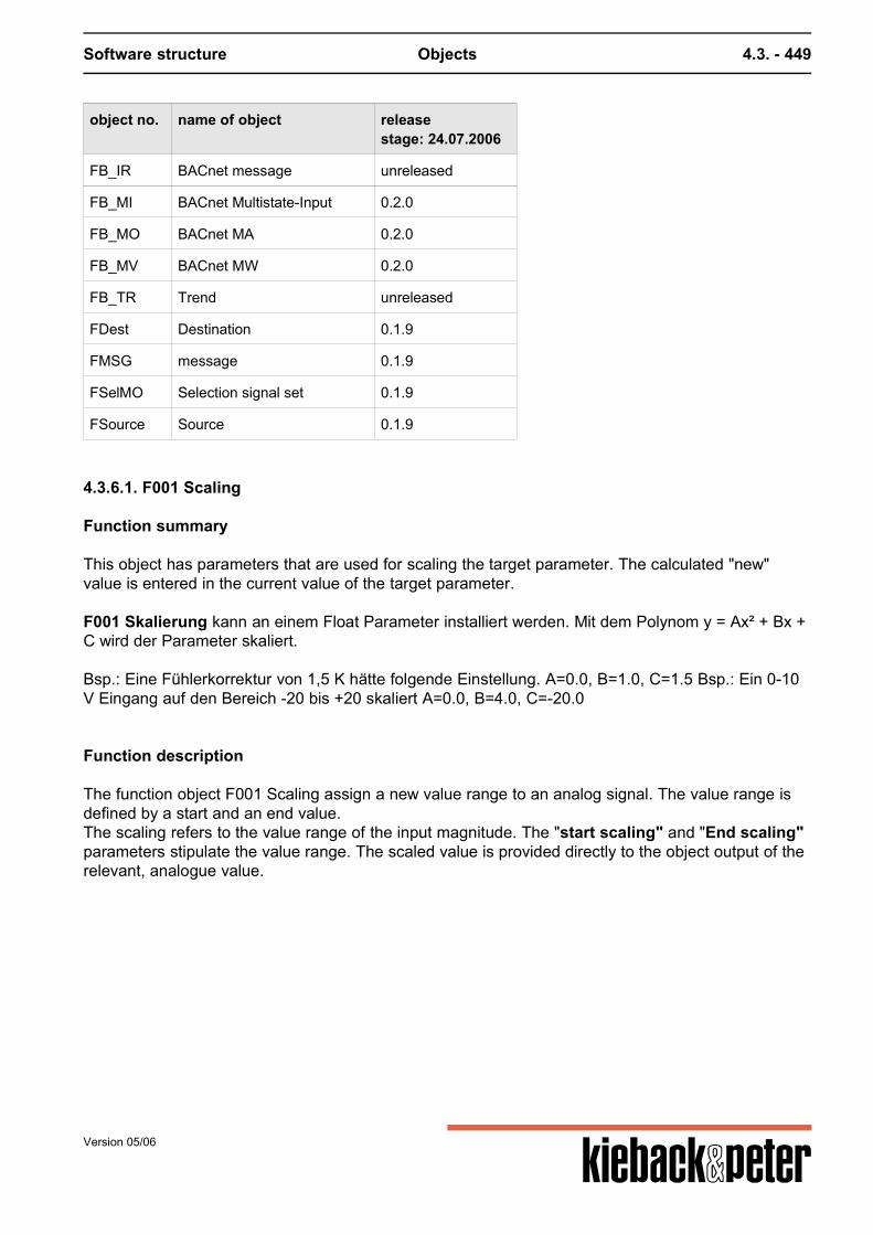
Software structure Objects 4.3. - 449
object no. name of object releasestage: 24.07.2006
FB_IR BACnet message unreleased
FB_MI BACnet Multistate-Input 0.2.0
FB_MO BACnet MA 0.2.0
FB_MV BACnet MW 0.2.0
FB_TR Trend unreleased
FDest Destination 0.1.9
FMSG message 0.1.9
FSelMO Selection signal set 0.1.9
FSource Source 0.1.9
4.3.6.1. F001 Scaling
Function summary
This object has parameters that are used for scaling the target parameter. The calculated "new"value is entered in the current value of the target parameter.
F001 Skalierung kann an einem Float Parameter installiert werden. Mit dem Polynom y = Ax² + Bx +C wird der Parameter skaliert.
Bsp.: Eine Fühlerkorrektur von 1,5 K hätte folgende Einstellung. A=0.0, B=1.0, C=1.5 Bsp.: Ein 0-10V Eingang auf den Bereich -20 bis +20 skaliert A=0.0, B=4.0, C=-20.0
Function description
The function object F001 Scaling assign a new value range to an analog signal. The value range isdefined by a start and an end value.The scaling refers to the value range of the input magnitude. The "start scaling" and "End scaling"parameters stipulate the value range. The scaled value is provided directly to the object output of therelevant, analogue value.
Version 05/06
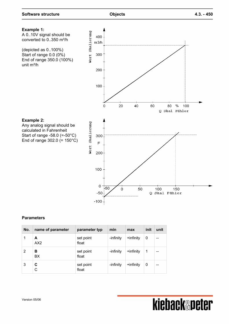
Software structure Objects 4.3. - 450
Example 1:A 0..10V signal should beconverted to 0..350 m³/h
(depicted as 0..100%)Start of range 0.0 (0%)End of range 350.0 (100%)unit m³/h
Example 2:Any analog signal should becalculated in FahrenheitStart of range -58.0 (=-50°C)End of range 302.0 (= 150°C)
Parameters
No. name of parameter parameter typ min max init unit
1 AAX2
set pointfloat
-infinity +infinity 0 --
2 BBX
set pointfloat
-infinity +infinity 1 --
3 CC
set pointfloat
-infinity +infinity 0 --
Version 05/06
Software structure Objects 4.3. - 451
4.3.6.3. F003 Limitation
Function summary
This object has parameters that are used for limiting the target parameter. The calculated "new"value is entered in the current value of the target parameter. The limitation is used for analog values. e.g. the customer should be able to set set point <xs> only between 19 ... 23°C although the valuerange envisages a greater range of values for the parameter <xs>.
Parameters
No. name of parameter parameter typ min max init unit
OG GWOUpper limit value
set pointfloat
-infinity +infinity 0 --
UG GWULower limit value
set pointfloat
-infinity +infinity 0 --
4.3.6.4. F004 catch
Function summary
Used to maintain a status of a parameter. The setting of another parameter releases the status of theparameter that is to be retained on which the catch works.
Function description
Die Selbsthaltung kann nur an einen Parameter vom Typ "Boolean" angehängt werden. Dies bewirkt,wenn der Parameter auf "1" wechselt, dass er durch die Selbsthaltung auf diesem Wert bleibt, bis einseparates Rücksetzsignal (Reset Störungsselbsthaltung) aktiviert wird. Erst nach Quittierung derÄnderung durch diese binäre Quelle wird der neue Wert gültig.
Parameters
No. name of parameter parameter typ min max init unit
1 resReset SH
set pointboolean
-- -- 0 --
4.3.6.5. F005 Command execution check
Function summary
Sie dient der Überwachung von binären Betriebs-Ist-Zuständen. Ein Betriebs-Ist-Zustand (oderBetriebsmeldung) muss innerhalb einer bestimmten Zeit tCEC dem Wert eines Betrieb-Soll-
Version 05/06
Software structure Objects 4.3. - 452
Zustandes entsprechen, anderenfalls wird ein binärer Ausgang FehlerBAK auf 1 gesetzt. Ist derBetriebs-Ist-Zustand nicht beschaltet, wird kein FehlerCEC signalisiert. Der FehlerCEC wirdzurückgesetzt, wenn der ResCEC-Eingang von 0 auf 1 wechselt. Ist der ResCEC-Eingang nichtbeschaltet, wird FehlerCEC zurückgesetzt, wenn der Betriebs-Ist-Zustand dem Betriebs-Soll-Zustand wieder entspricht. Die 0/1-Flanke von FehlerCEC wird um die Zeit VzCEC verzögertausgegeben. (siehe Pkt. 4.3.3.4 CEC)
Parameters
No. name of parameter parameter typ min max init unit
1 resetReset
set point deletableboolean
-- -- deleted --
2 zeitTime
set pointinteger
1 60 10 s
3 FehlerError input
set point deletableboolean
-- -- deleted --
4 AktorFeedback
set point deletableboolean
-- -- deleted --
4.3.6.6. F006 Damping
Function summary
This object has parameters that are used for damping the target parameter. The calculated "new"value is entered in the current value of the target parameter.
Function description
Es kann eine Beruhigung eines analogen Signals, z.B. eines Fühlerwertes, realisiert werden. DerParameter „tn“ wirkt dabei wie ein PT1-Glied. Ändert sich der Wert des Eingangssignals sprunghaft,so wird nach der Dämpfungszeit eine Änderung des Wertes von 63% des ursprünglichenEingangssprunges erreicht.
Parameters
No. name of parameter parameter typ min max init unit
1 tntn(63%)
set point deletableinteger
1 3600 deleted s
Version 05/06
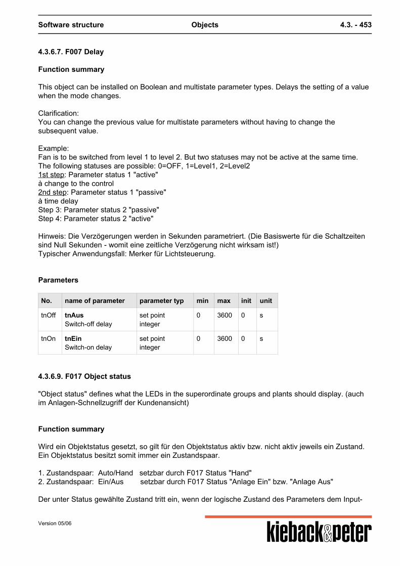
Software structure Objects 4.3. - 453
4.3.6.7. F007 Delay
Function summary
This object can be installed on Boolean and multistate parameter types. Delays the setting of a valuewhen the mode changes. Clarification:You can change the previous value for multistate parameters without having to change thesubsequent value. Example:Fan is to be switched from level 1 to level 2. But two statuses may not be active at the same time.The following statuses are possible: 0=OFF, 1=Level1, 2=Level21st step: Parameter status 1 "active"à change to the control2nd step: Parameter status 1 "passive"à time delayStep 3: Parameter status 2 "passive"Step 4: Parameter status 2 "active"
Hinweis: Die Verzögerungen werden in Sekunden parametriert. (Die Basiswerte für die Schaltzeitensind Null Sekunden - womit eine zeitliche Verzögerung nicht wirksam ist!)Typischer Anwendungsfall: Merker für Lichtsteuerung.
Parameters
No. name of parameter parameter typ min max init unit
tnOff tnAusSwitch-off delay
set pointinteger
0 3600 0 s
tnOn tnEinSwitch-on delay
set pointinteger
0 3600 0 s
4.3.6.9. F017 Object status
"Object status" defines what the LEDs in the superordinate groups and plants should display. (auchim Anlagen-Schnellzugriff der Kundenansicht)
Function summary
Wird ein Objektstatus gesetzt, so gilt für den Objektstatus aktiv bzw. nicht aktiv jeweils ein Zustand.Ein Objektstatus besitzt somit immer ein Zustandspaar.
1. Zustandspaar: Auto/Hand setzbar durch F017 Status "Hand"2. Zustandspaar: Ein/Aus setzbar durch F017 Status "Anlage Ein" bzw. "Anlage Aus"
Der unter Status gewählte Zustand tritt ein, wenn der logische Zustand des Parameters dem Input-
Version 05/06
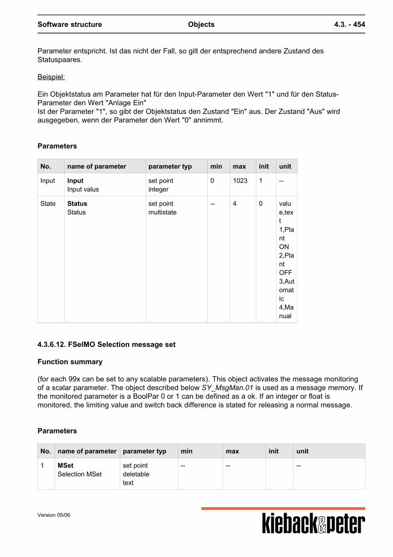
Software structure Objects 4.3. - 454
Parameter entspricht. Ist das nicht der Fall, so gilt der entsprechend andere Zustand desStatuspaares.
Beispiel:
Ein Objektstatus am Parameter hat für den Input-Parameter den Wert "1" und für den Status-Parameter den Wert "Anlage Ein"Ist der Parameter "1", so gibt der Objektstatus den Zustand "Ein" aus. Der Zustand "Aus" wirdausgegeben, wenn der Parameter den Wert "0" annimmt.
Parameters
No. name of parameter parameter typ min max init unit
Input InputInput valus
set pointinteger
0 1023 1 --
State StatusStatus
set pointmultistate
-- 4 0 value,text1,PlantON2,PlantOFF3,Automatic4,Manual
4.3.6.12. FSelMO Selection message set
Function summary
(for each 99x can be set to any scalable parameters). This object activates the message monitoringof a scalar parameter. The object described below SY_MsgMan.01 is used as a message memory. Ifthe monitored parameter is a BoolPar 0 or 1 can be defined as a ok. If an integer or float ismonitored, the limiting value and switch back difference is stated for releasing a normal message.
Parameters
No. name of parameter parameter typ min max init unit
1 MSetSelection MSet
set pointdeletabletext
-- -- --
Version 05/06
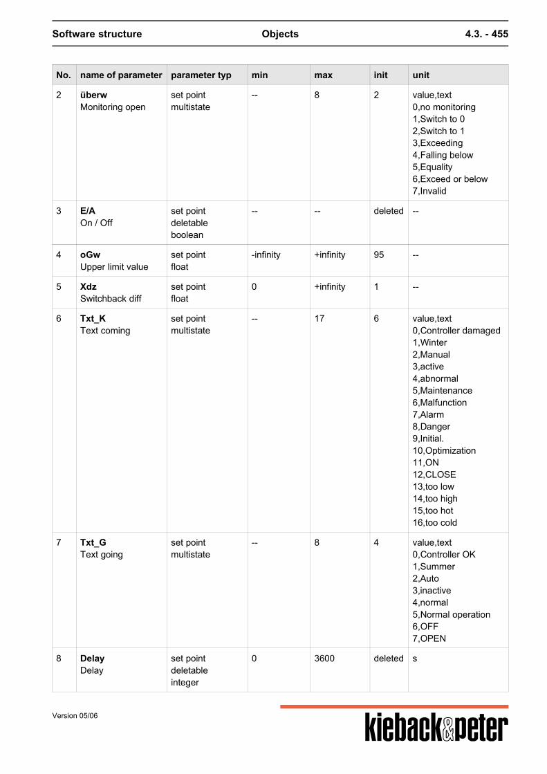
Software structure Objects 4.3. - 455
No. name of parameter parameter typ min max init unit
2 überwMonitoring open
set pointmultistate
-- 8 2 value,text0,no monitoring1,Switch to 02,Switch to 13,Exceeding4,Falling below5,Equality6,Exceed or below7,Invalid
3 E/AOn / Off
set pointdeletableboolean
-- -- deleted --
4 oGwUpper limit value
set pointfloat
-infinity +infinity 95 --
5 XdzSwitchback diff
set pointfloat
0 +infinity 1 --
6 Txt_KText coming
set pointmultistate
-- 17 6 value,text0,Controller damaged1,Winter2,Manual3,active4,abnormal5,Maintenance6,Malfunction7,Alarm8,Danger9,Initial.10,Optimization11,ON12,CLOSE13,too low14,too high15,too hot16,too cold
7 Txt_GText going
set pointmultistate
-- 8 4 value,text0,Controller OK1,Summer2,Auto3,inactive4,normal5,Normal operation6,OFF7,OPEN
8 DelayDelay
set pointdeletableinteger
0 3600 deleted s
Version 05/06
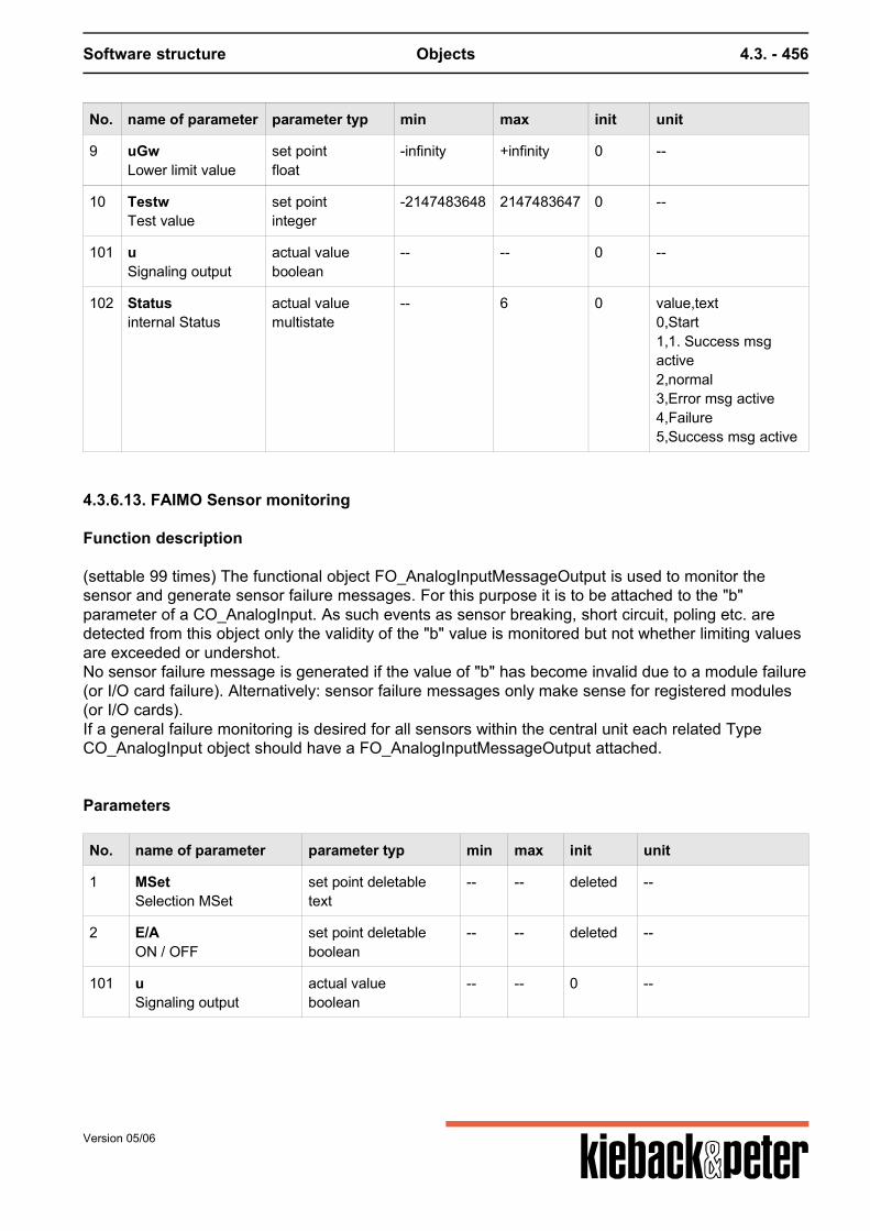
Software structure Objects 4.3. - 456
No. name of parameter parameter typ min max init unit
9 uGwLower limit value
set pointfloat
-infinity +infinity 0 --
10 TestwTest value
set pointinteger
-2147483648 2147483647 0 --
101 uSignaling output
actual valueboolean
-- -- 0 --
102 Statusinternal Status
actual valuemultistate
-- 6 0 value,text0,Start1,1. Success msgactive2,normal3,Error msg active4,Failure5,Success msg active
4.3.6.13. FAIMO Sensor monitoring
Function description
(settable 99 times) The functional object FO_AnalogInputMessageOutput is used to monitor thesensor and generate sensor failure messages. For this purpose it is to be attached to the "b"parameter of a CO_AnalogInput. As such events as sensor breaking, short circuit, poling etc. aredetected from this object only the validity of the "b" value is monitored but not whether limiting valuesare exceeded or undershot.No sensor failure message is generated if the value of "b" has become invalid due to a module failure(or I/O card failure). Alternatively: sensor failure messages only make sense for registered modules(or I/O cards).If a general failure monitoring is desired for all sensors within the central unit each related TypeCO_AnalogInput object should have a FO_AnalogInputMessageOutput attached.
Parameters
No. name of parameter parameter typ min max init unit
1 MSetSelection MSet
set point deletabletext
-- -- deleted --
2 E/AON / OFF
set point deletableboolean
-- -- deleted --
101 uSignaling output
actual valueboolean
-- -- 0 --
Version 05/06
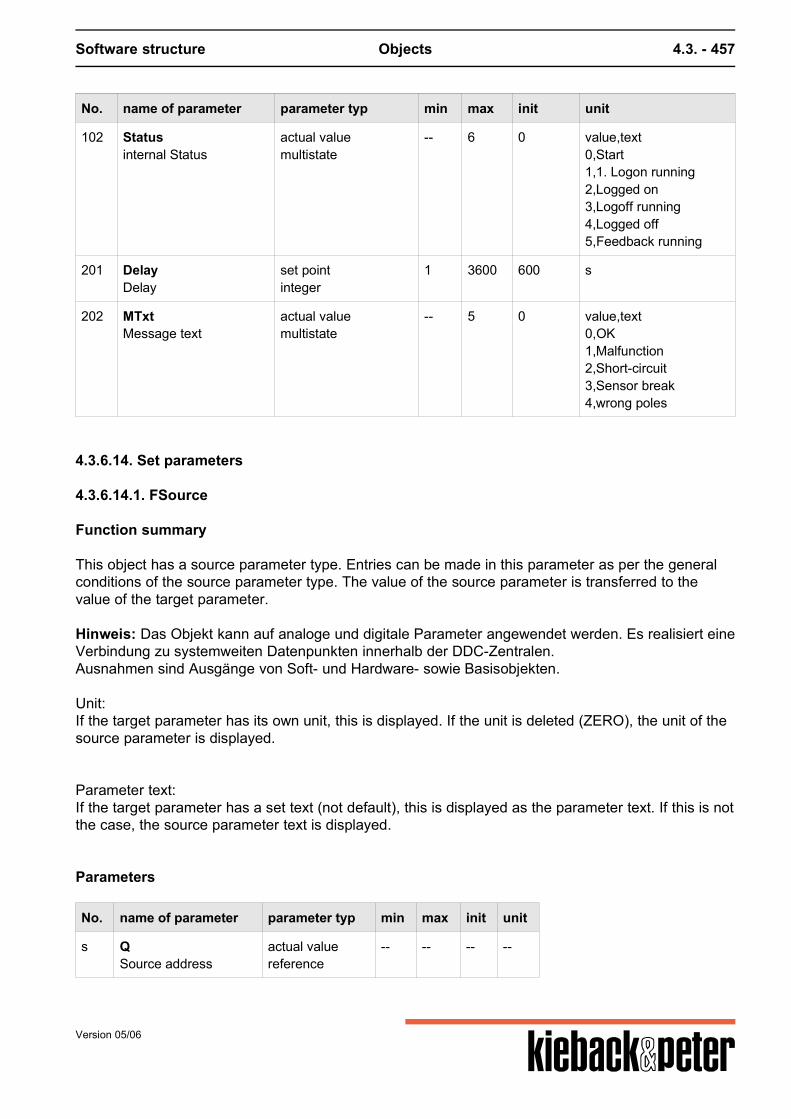
Software structure Objects 4.3. - 457
No. name of parameter parameter typ min max init unit
102 Statusinternal Status
actual valuemultistate
-- 6 0 value,text0,Start1,1. Logon running2,Logged on3,Logoff running4,Logged off5,Feedback running
201 DelayDelay
set pointinteger
1 3600 600 s
202 MTxtMessage text
actual valuemultistate
-- 5 0 value,text0,OK1,Malfunction2,Short-circuit3,Sensor break4,wrong poles
4.3.6.14. Set parameters
4.3.6.14.1. FSource
Function summary
This object has a source parameter type. Entries can be made in this parameter as per the generalconditions of the source parameter type. The value of the source parameter is transferred to thevalue of the target parameter. Hinweis: Das Objekt kann auf analoge und digitale Parameter angewendet werden. Es realisiert eineVerbindung zu systemweiten Datenpunkten innerhalb der DDC-Zentralen.Ausnahmen sind Ausgänge von Soft- und Hardware- sowie Basisobjekten. Unit:If the target parameter has its own unit, this is displayed. If the unit is deleted (ZERO), the unit of thesource parameter is displayed. Parameter text:If the target parameter has a set text (not default), this is displayed as the parameter text. If this is notthe case, the source parameter text is displayed.
Parameters
No. name of parameter parameter typ min max init unit
s QSource address
actual valuereference
-- -- -- --
Version 05/06
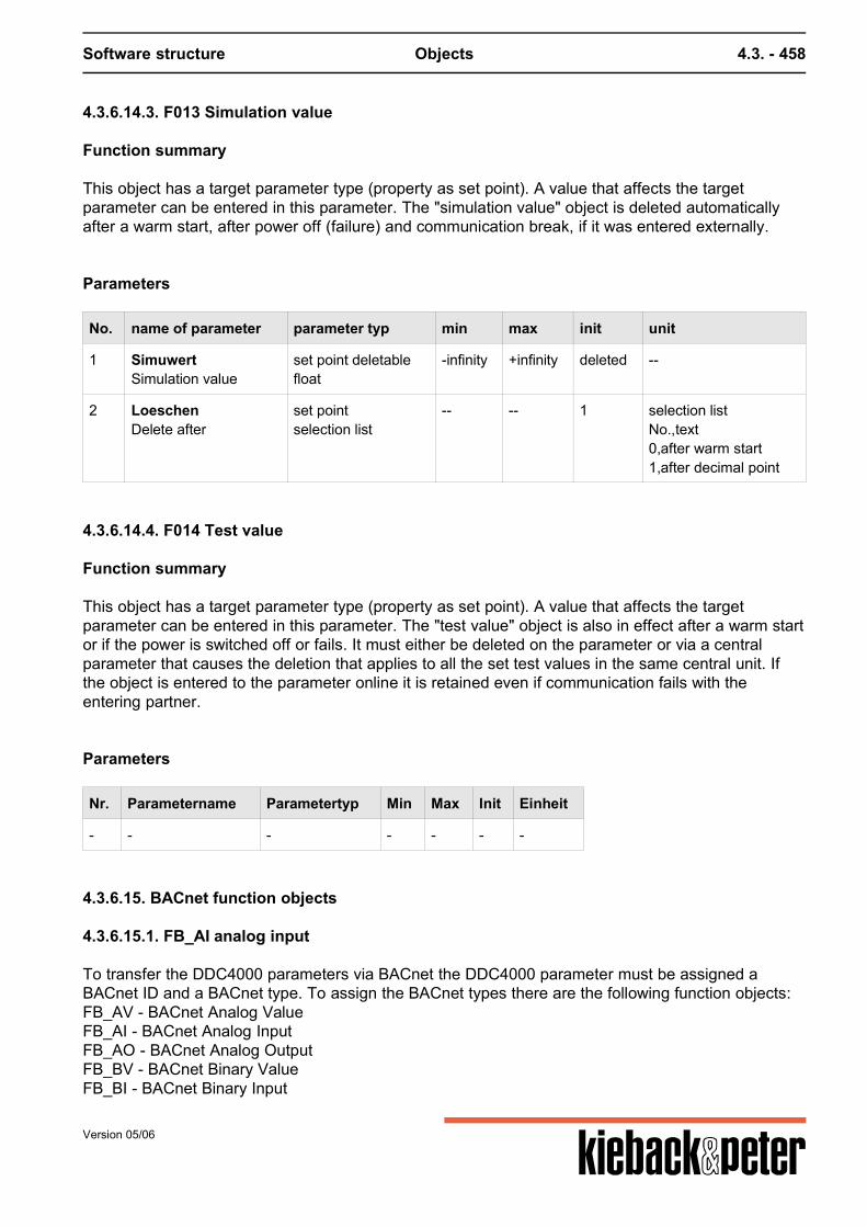
Software structure Objects 4.3. - 458
4.3.6.14.3. F013 Simulation value
Function summary
This object has a target parameter type (property as set point). A value that affects the targetparameter can be entered in this parameter. The "simulation value" object is deleted automaticallyafter a warm start, after power off (failure) and communication break, if it was entered externally.
Parameters
No. name of parameter parameter typ min max init unit
1 SimuwertSimulation value
set point deletablefloat
-infinity +infinity deleted --
2 LoeschenDelete after
set pointselection list
-- -- 1 selection listNo.,text0,after warm start1,after decimal point
4.3.6.14.4. F014 Test value
Function summary
This object has a target parameter type (property as set point). A value that affects the targetparameter can be entered in this parameter. The "test value" object is also in effect after a warm startor if the power is switched off or fails. It must either be deleted on the parameter or via a centralparameter that causes the deletion that applies to all the set test values in the same central unit. Ifthe object is entered to the parameter online it is retained even if communication fails with theentering partner.
Parameters
Nr. Parametername Parametertyp Min Max Init Einheit
- - - - - - -
4.3.6.15. BACnet function objects
4.3.6.15.1. FB_AI analog input
To transfer the DDC4000 parameters via BACnet the DDC4000 parameter must be assigned aBACnet ID and a BACnet type. To assign the BACnet types there are the following function objects:FB_AV - BACnet Analog ValueFB_AI - BACnet Analog InputFB_AO - BACnet Analog OutputFB_BV - BACnet Binary ValueFB_BI - BACnet Binary Input
Version 05/06
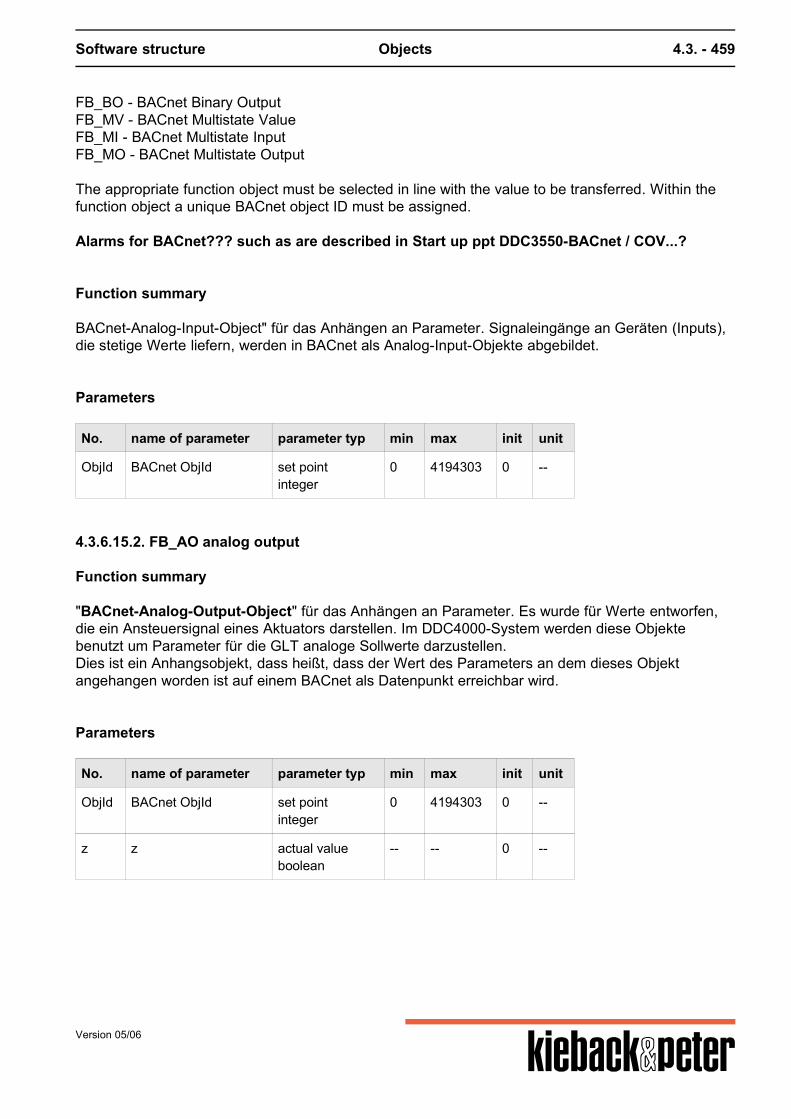
Software structure Objects 4.3. - 459
FB_BO - BACnet Binary OutputFB_MV - BACnet Multistate ValueFB_MI - BACnet Multistate InputFB_MO - BACnet Multistate Output The appropriate function object must be selected in line with the value to be transferred. Within thefunction object a unique BACnet object ID must be assigned. Alarms for BACnet??? such as are described in Start up ppt DDC3550-BACnet / COV...?
Function summary
BACnet-Analog-Input-Object" für das Anhängen an Parameter. Signaleingänge an Geräten (Inputs),die stetige Werte liefern, werden in BACnet als Analog-Input-Objekte abgebildet.
Parameters
No. name of parameter parameter typ min max init unit
ObjId BACnet ObjId set pointinteger
0 4194303 0 --
4.3.6.15.2. FB_AO analog output
Function summary
"BACnet-Analog-Output-Object" für das Anhängen an Parameter. Es wurde für Werte entworfen,die ein Ansteuersignal eines Aktuators darstellen. Im DDC4000-System werden diese Objektebenutzt um Parameter für die GLT analoge Sollwerte darzustellen.Dies ist ein Anhangsobjekt, dass heißt, dass der Wert des Parameters an dem dieses Objektangehangen worden ist auf einem BACnet als Datenpunkt erreichbar wird.
Parameters
No. name of parameter parameter typ min max init unit
ObjId BACnet ObjId set pointinteger
0 4194303 0 --
z z actual valueboolean
-- -- 0 --
Version 05/06
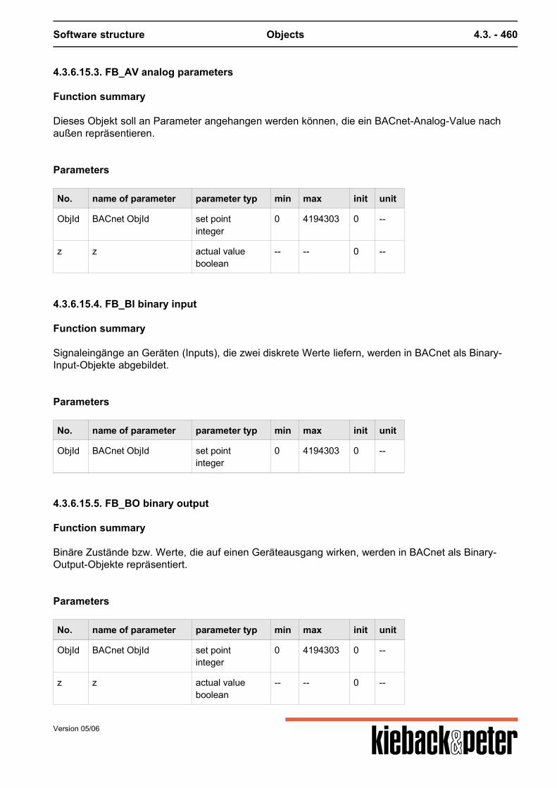
Software structure Objects 4.3. - 460
4.3.6.15.3. FB_AV analog parameters
Function summary
Dieses Objekt soll an Parameter angehangen werden können, die ein BACnet-Analog-Value nachaußen repräsentieren.
Parameters
No. name of parameter parameter typ min max init unit
ObjId BACnet ObjId set pointinteger
0 4194303 0 --
z z actual valueboolean
-- -- 0 --
4.3.6.15.4. FB_BI binary input
Function summary
Signaleingänge an Geräten (Inputs), die zwei diskrete Werte liefern, werden in BACnet als Binary-Input-Objekte abgebildet.
Parameters
No. name of parameter parameter typ min max init unit
ObjId BACnet ObjId set pointinteger
0 4194303 0 --
4.3.6.15.5. FB_BO binary output
Function summary
Binäre Zustände bzw. Werte, die auf einen Geräteausgang wirken, werden in BACnet als Binary-Output-Objekte repräsentiert.
Parameters
No. name of parameter parameter typ min max init unit
ObjId BACnet ObjId set pointinteger
0 4194303 0 --
z z actual valueboolean
-- -- 0 --
Version 05/06
Software structure Objects 4.3. - 461
4.3.6.15.6. FB_BV binary parameters
Function summary
Dies ist ein an Parameter anhängbares DDC-Funktions-Objekt oder auch Anhangsobjekt. Es bewirkt,dass der Wert eines Parameters als ein BACnet-Binary-Value-Objekt auf dem BACnet sichtbar wird.Dieses Objekt ist als Anhangsobjekt für Parameter vom Typ Boolean konzipiert.
Parameters
No. name of parameter parameter typ min max init unit
ObjId BACnet ObjId set pointinteger
0 4194303 0 --
z z actual valueboolean
-- -- 0 --
4.3.6.15.7. FB_MI multistate input
Function summary
Signaleingänge an Geräten (Inputs), die mehr als zwei diskrete Werte liefern, können in BACnet alsMultistate-Input-Objekte abgebildet werden.
Parameters
No. name of parameter parameter typ min max init unit
ObjId BACnet ObjId set pointinteger
0 4194303 0 --
4.3.6.15.8. FB_MO multistate output
Function summary
Analoge Werte, die auf einen Geräteausgang wirken, werden im BACnet als Multistate-Input-Objekteabgebildet.
Parameters
No. name of parameter parameter typ min max init unit
ObjId BACnet ObjId set pointinteger
0 4194303 0 --
Version 05/06
Software structure Objects 4.3. - 462
No. name of parameter parameter typ min max init unit
z z actual valueboolean
-- -- 0 --
4.3.6.15.9. FB_MV multistate parameters
Function summary
Dieses Objekt kann an Parameter des Typs Multistate angehangen werden.Dies bewirkt, dass der Parameter, an dem dieses Objekt angehangen worden ist, auf dem BACnetals BACnet-Multistate-Value-Objekt sichtbar wird.
Parameters
No. name of parameter parameter typ min max init unit
ObjId BACnet ObjId set pointinteger
0 4194303 0 --
z z actual valueboolean
-- -- 0 --
4.3.7. Sub-objects
4.3.7.1. Sub-objects
Sub-objects are definitions for the functions of certain objects. These sub-objects are used forexample for outputs and inputs. A PIN object only receives its function by stipulating the type of sub-objects (e.g. binary input or output). Sub-objects are used for example for SBM51 PIN objects FBM38
object no. name of object releasestage: 24.07.2006
CAI Analog input 0.1.9
CAO Analog output 0.1.9
CB_NC BACnetMsgDest unreleased
CDI Binary input 0.1.9
CDO Binary output 0.1.9
Version 05/06
Software structure Objects 4.3. - 463
object no. name of object releasestage: 24.07.2006
CD_EL Electrical counter unreleased
CD_PU01 Basic fos max. 0.3.33
CD_PU02 Wilo Pump 0.3.33
CD_PU03 Double pump unreleased
CD_SB51 SBM51 Menu unreleased
CD_SB51S Sim unreleased
CD_WA Water counter unreleased
CD_WA01 Water counter unreleased
CD_WA02 Water counter unreleased
CD_WM Heat counter 0.2.0
CD_WM01 Heat counter 0.2.0
CEth Ethernet 0.3.33
CLI088 SNVT Alarm unreleased
CLI095 SNVT Switch unreleased
CLI106 SNVT Setpoint unreleased
CLI108 SNVT HVAC Mode unreleased
CLI109 SNVT Occupancy unreleased
CLI112 HVAC Status unreleased
CLI117 SNVT Setting unreleased
CLO088 SNVT Alarm unreleased
CLO095 SNVT Switch unreleased
CLO106 SNVT Setpoint unreleased
CLO108 SNVT HVAC Mode unreleased
CLO109 SNVT Occupancy unreleased
CLO112 HVAC Status unreleased
CLO117 SNVT Setting unreleased
CModMO Module message 0.3
CPort Port 0.3.33
CRS232 RS485 IP-conf. 0.3
CRS485 RS485 IP-conf. 0.3
Version 05/06
Software structure Objects 4.3. - 464
object no. name of object releasestage: 24.07.2006
CUser User 0.1.9
4.3.7.2. CAI analog input
Function summary
Dieses Subobjekt stellt alle Funktionen und Parameter eines analogen Eingangs zur Verfügung. Esist Bestandteil des PIN Objektes und kann dort durch den Konfigurations-Parameter aktiviert werden.
Parameters
No. name of parameter parameter typ min max init unit
b bb
actual value deletablefloat
-infinity +infinity deleted C
SType FTypSensor type
set pointmultistate
-- 10 1 value,text0,0_10V1,KP102,Pt1003,Pt10004,Ni1005,Ni1000 (DIN)6,Ni1000 (L&G)7,KP2508,ML2255,off
4.3.7.3. CAO analog output
Function summary
Dieses Subobjekt stellt alle Funktionen und Parameter eines analogen Ausgangs zur Verfügung. Esist Bestandteil des PIN Objektes und kann dort durch den Konfigurations-Parameter aktiviert werden.
Parameters
No. name of parameter parameter typ min max init unit
y yy Input
actual value deletablefloat
-infinity +infinity deleted %
Y YY Output
set pointfloat
0 100 0 %
Version 05/06
Software structure Objects 4.3. - 465
4.3.7.4. CDI binary input
Function summary
Dieses Subobjekt stellt alle Funktionen und Parameter eines binären Eingangs zur Verfügung. Es istBestandteil des PIN Objektes und kann dort durch den Konfigurations-Parameter aktiviert werden.
Parameters
No. name of parameter parameter typ min max init unit
k akt.kValue BE
actual value deletableboolean
-- -- deleted --
4.3.7.5. CDO binary output
Function summary
Dieses Subobjekt stellt alle Funktionen und Parameter eines binären Ausgangs zur Verfügung. Es istBestandteil des PIN Objektes und kann dort durch den Konfigurations-Parameter aktiviert werden.
Parameters
No. name of parameter parameter typ min max init unit
k akt.KActual value BA
actual value deletableboolean
-- -- deleted --
K KBinary output
set pointboolean
-- -- 0 --
4.3.7.6. CModMO
Function summary
(99x settable) This object is attached to objects from the Type SY_Module and is used to produce"module failure" plant messages. The "malfunction", "ErrNo", "DubAdr" and "Active" parameters foreach SY_Module are monitored and if there is an ongoing malfunction in one of these parameters acorresponding plant message is generated. This message is distributed as per the plant messagesby selecting a relevant message set.
Version 05/06
Software structure Objects 4.3. - 466
Parameters
No. name of parameter parameter typ min max init unit
1 MSetSelection MSet
set point deletabletext
-- -- deleted --
2 E/AON / OFF
set point deletableboolean
-- -- deleted --
101 uModule message
actual valueboolean
-- -- 0 --
102 Statusinternal Status
actual valuemultistate
-- 6 0 value,text0,Start1,1. Logon running2,Logged on3,Logoff running4,Logged off5,Feedback running
201 DelayDelay
set pointinteger
1 3600 600 s
202 MTxtMessage text
actual valuemultistate
-- 5 0 value,text0,OK1,double address2,Fault module3,Malfunction4,Fault Code
4.3.8. Device objects
4.3.8.1. Gateway Objects
4.3.8.2. Volume counter
4.3.8.2.1. CD_WA volume counter
Function summary
Dies ist ein Subobjekt für die wichtigsten Parameter eines Wasser-Zählers. Die hier enthaltenenParameter sind das Minimum, das man von einem Wasserzähler erwarten kann.
Parameters
No. name of parameter parameter typ min max init unit
2222 StörZählFault counter
actual valueboolean
-- -- 0 --
Version 05/06
Software structure Objects 4.3. - 467
No. name of parameter parameter typ min max init unit
2251 Ser-nrSerial number
actual valuetext
-- -- --
2258 Volumenvolume
actual valuefloat
-infinity +infinity 0 m
4.3.8.2.2. CD_WA Volume counter 01
Function summary
Dieses sind die Standard-Parameter eines Wasser-Zählers am M-Bus. Viele Wasser-Zähler am M-Bus bieten die hier enthaltenen Parameter an. Somit sind diese für viele Zähler geeignet,insbesondere auch für unbekannte Zähler.
Parameters
No. name of parameter parameter typ min max init unit
2212 Betr.stdOperating time
actual valueinteger
-2147483648 2147483647 0 h
2222 StörZählFault counter
actual valueboolean
-- -- 0 --
2251 Ser-nrSerial number
actual valuetext
-- -- --
2253 VolstromVolume current
actual valuefloat
-infinity +infinity 0 m/h
2258 Volumenvolume
actual valuefloat
-infinity +infinity 0 m
4.3.8.2.3. CD_WA Volume counter 02
Function summary
Die speziellen Parameter für den Wasser-Zähler "IZWM" von Allmess Schlumberger.
Parameters
No. name of parameter parameter typ min max init unit
2212 Betr.stdOperating time
actual valueinteger
-2147483648 2147483647 0 h
Version 05/06
Software structure Objects 4.3. - 468
No. name of parameter parameter typ min max init unit
2215 Volumen1Volume 1
actual valuefloat
-infinity +infinity 0 m
2222 StörZählFault counter
actual valueboolean
-- -- 0 --
2251 Ser-nrSerial number
actual valuetext
-- -- --
2252 Volumen2Volume 2
actual valuefloat
-infinity +infinity 0 m
4.3.8.3. Electrical counter
4.3.8.3.1. CD_WM Electrical counter
Function summary
Die wichtigsten Parameter eines Wärme-Zählers. Die hier enthaltenen Parameter sind das Minimum,das man von einem Wärmezähler erwarten kann.
Parameters
No. name of parameter parameter typ min max init unit
2211 Energieenergy
actual valuefloat
-infinity +infinity 0 kWh
2222 StörZählMalfunction message
actual valueboolean
-- -- 0 --
2251 Ser-nrSerial number
actual valuetext
-- -- --
4.3.8.3.2. CD_WM Electrical counter 01
Function summary
Die Standard-Parameter eines Wärme-Zählers am M-Bus. Viele Wärme-Zähler am M-Bus bieten diehier enthaltenen Parameter an. Somit sind diese für viele Wärme-Zähler geeignet, insbesondereauch für unbekannte Zähler.
Version 05/06
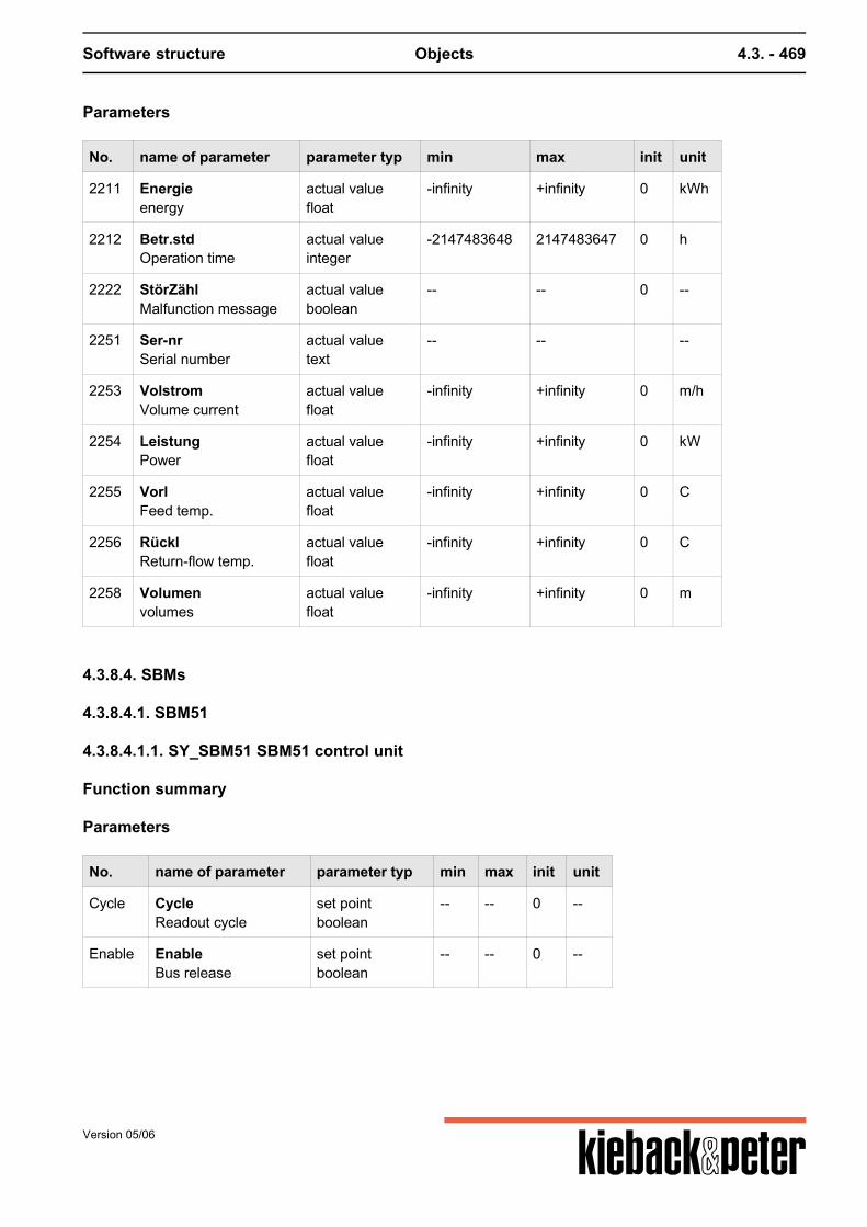
Software structure Objects 4.3. - 469
Parameters
No. name of parameter parameter typ min max init unit
2211 Energieenergy
actual valuefloat
-infinity +infinity 0 kWh
2212 Betr.stdOperation time
actual valueinteger
-2147483648 2147483647 0 h
2222 StörZählMalfunction message
actual valueboolean
-- -- 0 --
2251 Ser-nrSerial number
actual valuetext
-- -- --
2253 VolstromVolume current
actual valuefloat
-infinity +infinity 0 m/h
2254 LeistungPower
actual valuefloat
-infinity +infinity 0 kW
2255 VorlFeed temp.
actual valuefloat
-infinity +infinity 0 C
2256 RücklReturn-flow temp.
actual valuefloat
-infinity +infinity 0 C
2258 Volumenvolumes
actual valuefloat
-infinity +infinity 0 m
4.3.8.4. SBMs
4.3.8.4.1. SBM51
4.3.8.4.1.1. SY_SBM51 SBM51 control unit
Function summary
Parameters
No. name of parameter parameter typ min max init unit
Cycle CycleReadout cycle
set pointboolean
-- -- 0 --
Enable EnableBus release
set pointboolean
-- -- 0 --
Version 05/06
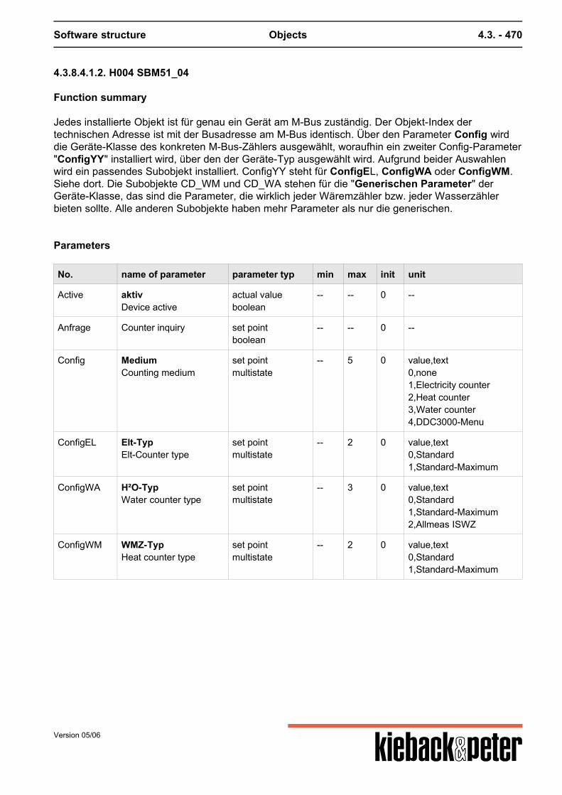
Software structure Objects 4.3. - 470
4.3.8.4.1.2. H004 SBM51_04
Function summary
Jedes installierte Objekt ist für genau ein Gerät am M-Bus zuständig. Der Objekt-Index dertechnischen Adresse ist mit der Busadresse am M-Bus identisch. Über den Parameter Config wirddie Geräte-Klasse des konkreten M-Bus-Zählers ausgewählt, woraufhin ein zweiter Config-Parameter"ConfigYY" installiert wird, über den der Geräte-Typ ausgewählt wird. Aufgrund beider Auswahlenwird ein passendes Subobjekt installiert. ConfigYY steht für ConfigEL, ConfigWA oder ConfigWM.Siehe dort. Die Subobjekte CD_WM und CD_WA stehen für die "Generischen Parameter" derGeräte-Klasse, das sind die Parameter, die wirklich jeder Wäremzähler bzw. jeder Wasserzählerbieten sollte. Alle anderen Subobjekte haben mehr Parameter als nur die generischen.
Parameters
No. name of parameter parameter typ min max init unit
Active aktivDevice active
actual valueboolean
-- -- 0 --
Anfrage Counter inquiry set pointboolean
-- -- 0 --
Config MediumCounting medium
set pointmultistate
-- 5 0 value,text0,none1,Electricity counter2,Heat counter3,Water counter4,DDC3000-Menu
ConfigEL Elt-TypElt-Counter type
set pointmultistate
-- 2 0 value,text0,Standard1,Standard-Maximum
ConfigWA H²O-TypWater counter type
set pointmultistate
-- 3 0 value,text0,Standard1,Standard-Maximum2,Allmeas ISWZ
ConfigWM WMZ-TypHeat counter type
set pointmultistate
-- 2 0 value,text0,Standard1,Standard-Maximum
Version 05/06
Software structure parameterizing 4.4. - 471
4.4. parameterizing
4.4.1. Plant structuring
The "plant" and "group" address components can be used for later reuse and structured approach.
4.4.1.1. Plants
Why plants?
All the functions of a technical building plant can be summarized in "plants". This may include acontact output or a full air conditioning plant.
The term "plant" is just a sorting criterion. It is mainly used for structured visualization. All plants areoffered to the user in the first operating page.
4.4.1.2. Groups
Why groups?
A group is a grouping of the functions from part of a plant. For example, a heating register can besummarized under a group. This would include e.g. the valve, sensor and pump. Within the "switch"page the group name would be inserted as a divider from the other LEDs.
A controller can be found in each group. Therefore an air conditioning plant for example can have atemperature control circuit in one group and a humidity control circuit in another group.
4.4.2. Malfunction message management
4.4.2.1. Plant messages
4.4.2.1.1. Messages
A message in the DDC4000 system is depicted via an attachment function FSelMo. The informationfor malfunctions (incoming message) and normal operation (outgoing message) are administrated. Plant messages are generated if an appropriate parameter monitoring has been set. Plant messages are generated in line with the status of the hardware of the separate controltechnology. Plant messages have a delay so that only ongoing failures are reported.
Version 05/06
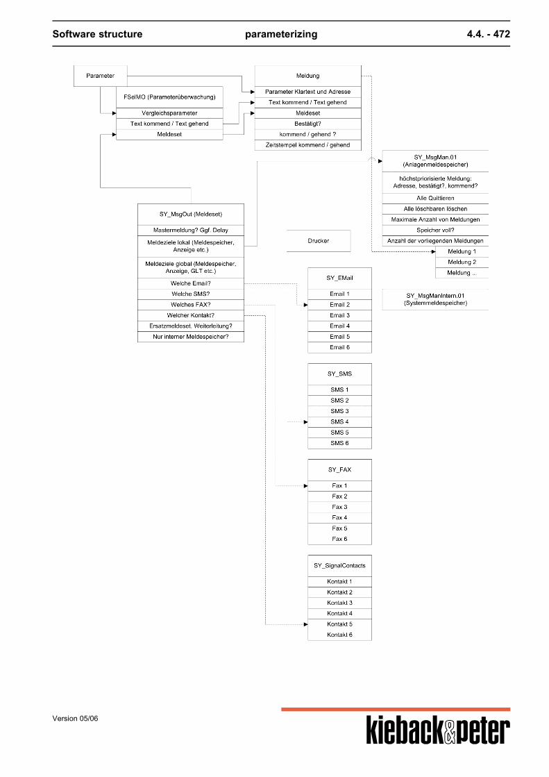
Software structure parameterizing 4.4. - 472
Version 05/06
Software structure parameterizing 4.4. - 473
Plant messages
Plant messages are used to monitor e.g. such malfunction statuses as malfunction messages orvalues exceeded e.g. for level monitoring. The following must be defined for plant monitoring:1. which parameter is to be monitored,2. where the message is displayed or to where it is transferred. Re (1)To monitor a parameter a sub-object FSelMO is installed on the relevant parameter. The type ofmonitoring can be stipulated with the parameters for the FSelMO object. Via parameter 3 E/A you switch the monitoring on or off. Parameter 2 monit stipulates,- whether '0' or '1' is the normal response (e.g. for binary parameters)- whether monitoring is for falling above or exceeding a limit (for numbers) or- whether equality or lack of equality is being monitored (for selection parameters or numbers). In parameter 4 value the comparison value is entered; this is compared with that of the monitoredparameter, such as parameter 2 monit. A hysteresis for the comparison value can be set in parameter 5 Xdz (switch back difference). Thisprevents the occurrence of many messages if the parameter being monitored moves around thecomparison value. This would produce messages time and again. In order to provide operating staff with useful information if a message is produced, a text can bedefined in parameter 6 Txt_IN and this is output with the message if the monitored status occurs.Correspondingly a further text 7 Txt_OU can be defined when a malfunction state is resolved. Theseare referred to as "incoming" and "outgoing" messages. The current monitoring result is shown on message output 101. After defining when a plant message is created, you must still define where and how it is displayed.For this a reference is entered on a s. g. message set (see below) in parameter 1 MSet. Re (2)Up to 20 message sets (system object SY_MesgOut) can be defined and these define separatelyfrom the message where and how messages are processed.
Plant messages
Plant messages are produced by the plant automatically. Plant messages can only be displayed on the relevant central unit; they are not transmitted to othercentral units. Certain groups of messages can be suppressed or displayed to facilitate trouble-shooting. Potential groups of plant messages:Central unit hardware
Version 05/06
Software structure parameterizing 4.4. - 474
modules of CAN buses,Ethernet bus (central bus)
4.4.2.1.3. Message memory SY_MsgMan
Function summary
(n x settable) This object is used as to save messages. When starting the plant in //000/00/00 theobject SY_MsgMan.01 of this type is created. All messages are attached to parameter 103 "akt AnzMeld".
Function description
If the maximum number of messages is reached a new message pushes out the message with thelowest priority. For this the following priority rules apply:
Priority class Message status Display on DDC4000 screen
1 (High) incoming, not quit red flashing triangle
2 incoming, quit red constant triangle
3 outgoing, not quit green flashing triangle
4 (Low) outgoing, quit green constant triangle
Within a priority class the oldest message has the lowest priority, and logically the newest messagethe highest.If the maximum number of messages in the message memory is reset to a value that is smaller thanthe current number of messages deletions are also made as per the rules described above until thenew maximum number is reached.
Parameters
No. name of parameter parameter typ min max init unit
101 neuMnew message
actual valueboolean
-- -- 0 --
102 quMSMS receipt
set point deletableboolean
-- -- deleted --
103 aktMact number msg
actual valueinteger
0 99 0 --
104 löMSMS delete
set point deletableboolean
-- -- deleted --
105 maxMmax number msg
set pointinteger
1 99 64 --
Version 05/06
Software structure parameterizing 4.4. - 475
No. name of parameter parameter typ min max init unit
106 vollMemory full
actual valueboolean
-- -- 0 --
107 kmdMcoming notification
actual valueboolean
-- -- 0 --
108 glob Löglobal delete
set point deletableboolean
-- -- deleted --
109 vip-IVIP Index
actual value deletableinteger
0 99 deleted --
4.4.2.1.4. Output definition SY_MsgOut
Function summary
(20x settable) In this object the output destinations ("message sets") are defined for messages.
In diesem Objekt werden die Ausgabe-Ziele („Melde-Sets“) von Meldungen definiert. ImMeldeüberwachungs-Objekt (FO_SelectionMessageOutput) kann im Parameter 1 „Auswahl Mset“ einMelde-Set eingetragen werden, welches die Ziele der generierten Meldungen festlegt. Weiterhinkann zur Verzögerung bzw. Verhinderung von Meldeschauern eine Master-Meldung generiertwerden.Falls das Versenden von Meldungen fehlgeschlagen ist, kann ein Ersatz-Meldeset eingetragenwerden.
Parameters
No. name of parameter parameter typ min max init unit
3 globDest. global
set pointboolean
-- -- 0 --
5 SMSSelection SMS
set pointselection list
-- -- 0 selection listNo.,text0,SMS No. 11,SMS No. 22,SMS No. 33,SMS No. 44,SMS No. 55,SMS No. 6
Version 05/06
Software structure parameterizing 4.4. - 476
No. name of parameter parameter typ min max init unit
6 FAXSelection FAX
set pointselection list
-- -- 0 selection listNo.,text0,FAX-No. 11,FAX-No. 22,FAX-No. 33,FAX-No. 44,FAX-No. 55,FAX-No. 6
7 DruckerSelection printer
set pointselection list
-- -- 0 selection listNo.,text0,Printer 11,Printer 22,Printer 33,Printer 44,Printer 55,Printer 6
8 ErsatzReplacement MSet
set point deletabletext
-- -- deleted --
9 weiterForwarding
set pointmultistate
-- 3 0 value,text0,no forwarding1,destination error2,no destination reached
201 intMSGoal Msp intern
set pointboolean
-- -- 0 --
4.4.2.1.5. Selection message set FSelMO
Function summary
(for each 99x can be set to any scalable parameters). This object activates the message monitoringof a scalar parameter. The object described below SY_MsgMan.01 is used as a message memory. Ifthe monitored parameter is a BoolPar 0 or 1 can be defined as a ok. If an integer or float ismonitored, the limiting value and switch back difference is stated for releasing a normal message.
Parameters
No. name of parameter parameter typ min max init unit
1 MSetSelection MSet
set pointdeletabletext
-- -- --
Version 05/06
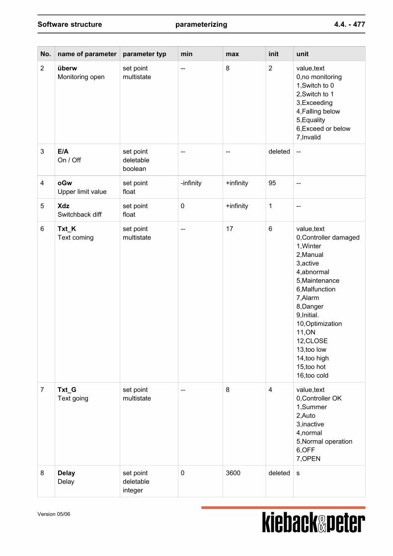
Software structure parameterizing 4.4. - 477
No. name of parameter parameter typ min max init unit
2 überwMonitoring open
set pointmultistate
-- 8 2 value,text0,no monitoring1,Switch to 02,Switch to 13,Exceeding4,Falling below5,Equality6,Exceed or below7,Invalid
3 E/AOn / Off
set pointdeletableboolean
-- -- deleted --
4 oGwUpper limit value
set pointfloat
-infinity +infinity 95 --
5 XdzSwitchback diff
set pointfloat
0 +infinity 1 --
6 Txt_KText coming
set pointmultistate
-- 17 6 value,text0,Controller damaged1,Winter2,Manual3,active4,abnormal5,Maintenance6,Malfunction7,Alarm8,Danger9,Initial.10,Optimization11,ON12,CLOSE13,too low14,too high15,too hot16,too cold
7 Txt_GText going
set pointmultistate
-- 8 4 value,text0,Controller OK1,Summer2,Auto3,inactive4,normal5,Normal operation6,OFF7,OPEN
8 DelayDelay
set pointdeletableinteger
0 3600 deleted s
Version 05/06
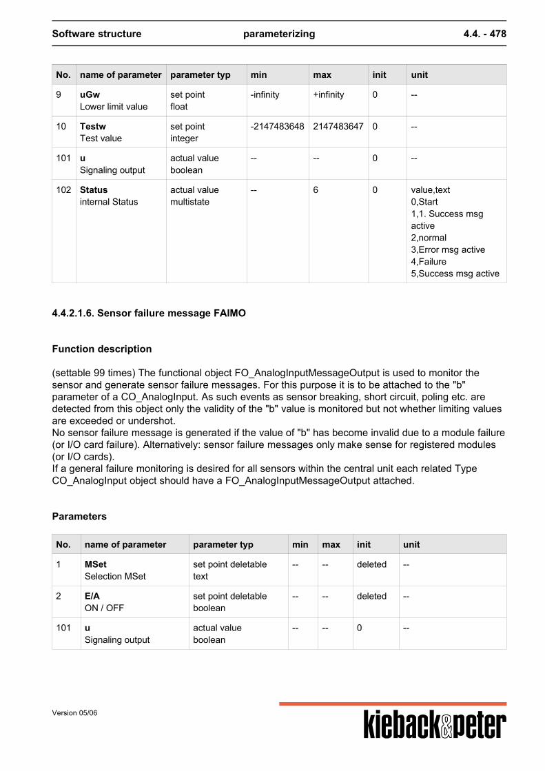
Software structure parameterizing 4.4. - 478
No. name of parameter parameter typ min max init unit
9 uGwLower limit value
set pointfloat
-infinity +infinity 0 --
10 TestwTest value
set pointinteger
-2147483648 2147483647 0 --
101 uSignaling output
actual valueboolean
-- -- 0 --
102 Statusinternal Status
actual valuemultistate
-- 6 0 value,text0,Start1,1. Success msgactive2,normal3,Error msg active4,Failure5,Success msg active
4.4.2.1.6. Sensor failure message FAIMO
Function description
(settable 99 times) The functional object FO_AnalogInputMessageOutput is used to monitor thesensor and generate sensor failure messages. For this purpose it is to be attached to the "b"parameter of a CO_AnalogInput. As such events as sensor breaking, short circuit, poling etc. aredetected from this object only the validity of the "b" value is monitored but not whether limiting valuesare exceeded or undershot.No sensor failure message is generated if the value of "b" has become invalid due to a module failure(or I/O card failure). Alternatively: sensor failure messages only make sense for registered modules(or I/O cards).If a general failure monitoring is desired for all sensors within the central unit each related TypeCO_AnalogInput object should have a FO_AnalogInputMessageOutput attached.
Parameters
No. name of parameter parameter typ min max init unit
1 MSetSelection MSet
set point deletabletext
-- -- deleted --
2 E/AON / OFF
set point deletableboolean
-- -- deleted --
101 uSignaling output
actual valueboolean
-- -- 0 --
Version 05/06
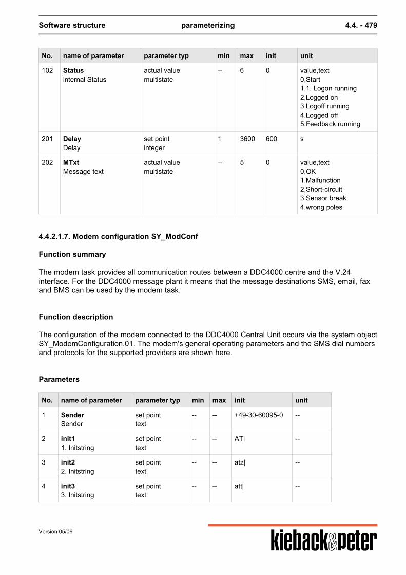
Software structure parameterizing 4.4. - 479
No. name of parameter parameter typ min max init unit
102 Statusinternal Status
actual valuemultistate
-- 6 0 value,text0,Start1,1. Logon running2,Logged on3,Logoff running4,Logged off5,Feedback running
201 DelayDelay
set pointinteger
1 3600 600 s
202 MTxtMessage text
actual valuemultistate
-- 5 0 value,text0,OK1,Malfunction2,Short-circuit3,Sensor break4,wrong poles
4.4.2.1.7. Modem configuration SY_ModConf
Function summary
The modem task provides all communication routes between a DDC4000 centre and the V.24interface. For the DDC4000 message plant it means that the message destinations SMS, email, faxand BMS can be used by the modem task.
Function description
The configuration of the modem connected to the DDC4000 Central Unit occurs via the system objectSY_ModemConfiguration.01. The modem's general operating parameters and the SMS dial numbersand protocols for the supported providers are shown here.
Parameters
No. name of parameter parameter typ min max init unit
1 SenderSender
set pointtext
-- -- +49-30-60095-0 --
2 init11. Initstring
set pointtext
-- -- AT| --
3 init22. Initstring
set pointtext
-- -- atz| --
4 init33. Initstring
set pointtext
-- -- att| --
Version 05/06
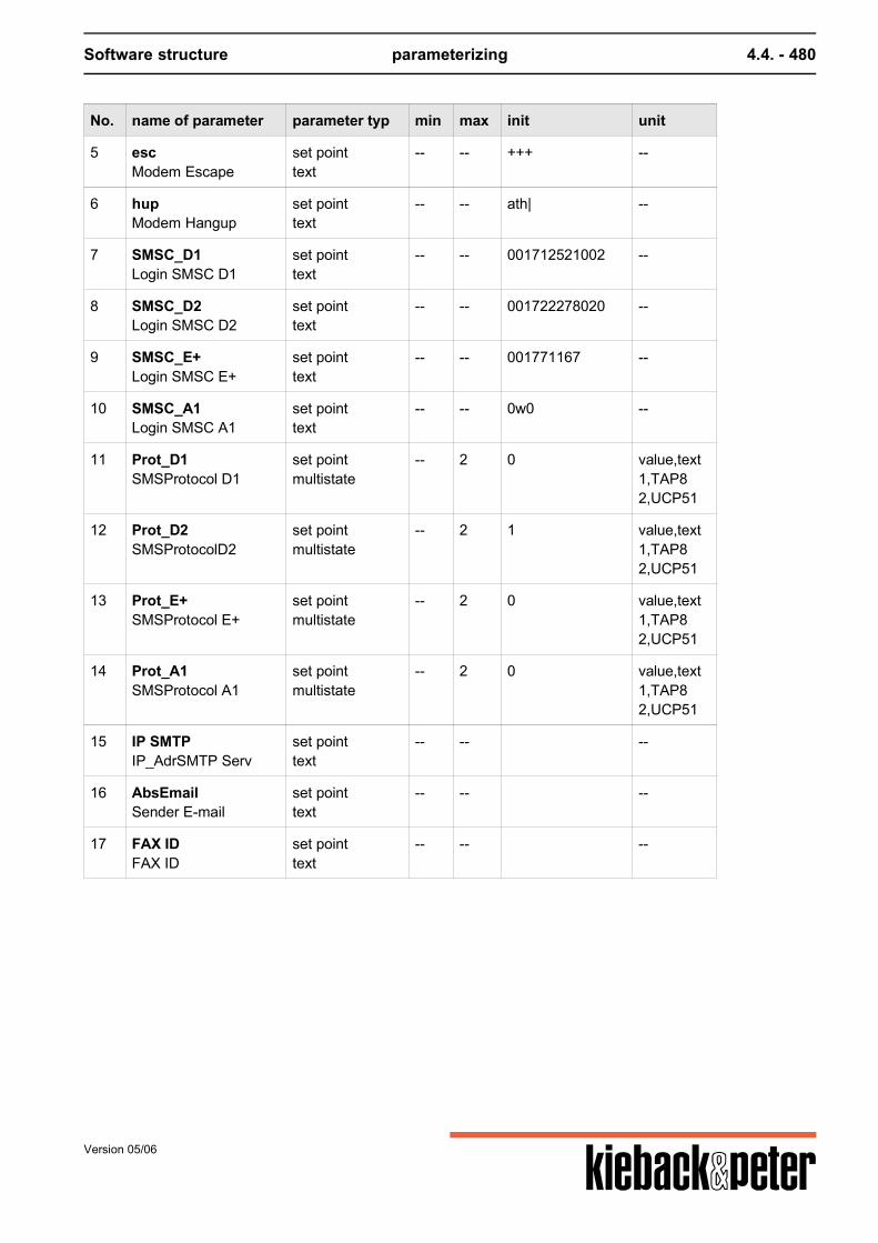
Software structure parameterizing 4.4. - 480
No. name of parameter parameter typ min max init unit
5 escModem Escape
set pointtext
-- -- +++ --
6 hupModem Hangup
set pointtext
-- -- ath| --
7 SMSC_D1Login SMSC D1
set pointtext
-- -- 001712521002 --
8 SMSC_D2Login SMSC D2
set pointtext
-- -- 001722278020 --
9 SMSC_E+Login SMSC E+
set pointtext
-- -- 001771167 --
10 SMSC_A1Login SMSC A1
set pointtext
-- -- 0w0 --
11 Prot_D1SMSProtocol D1
set pointmultistate
-- 2 0 value,text1,TAP82,UCP51
12 Prot_D2SMSProtocolD2
set pointmultistate
-- 2 1 value,text1,TAP82,UCP51
13 Prot_E+SMSProtocol E+
set pointmultistate
-- 2 0 value,text1,TAP82,UCP51
14 Prot_A1SMSProtocol A1
set pointmultistate
-- 2 0 value,text1,TAP82,UCP51
15 IP SMTPIP_AdrSMTP Serv
set pointtext
-- -- --
16 AbsEmailSender E-mail
set pointtext
-- -- --
17 FAX IDFAX ID
set pointtext
-- -- --
Version 05/06
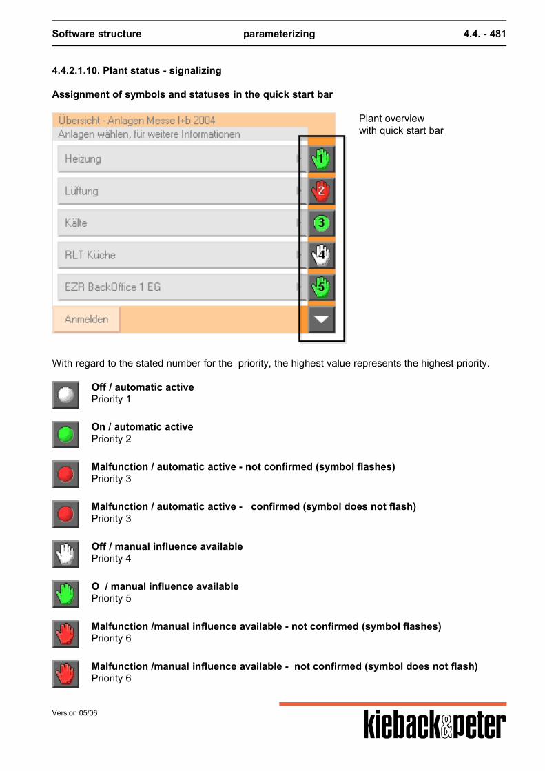
Software structure parameterizing 4.4. - 481
4.4.2.1.10. Plant status - signalizing
Assignment of symbols and statuses in the quick start bar
Plant overviewwith quick start bar
With regard to the stated number for the priority, the highest value represents the highest priority.
Off / automatic activePriority 1
On / automatic activePriority 2
Malfunction / automatic active - not confirmed (symbol flashes)Priority 3
Malfunction / automatic active - confirmed (symbol does not flash)Priority 3
Off / manual influence availablePriority 4
O / manual influence availablePriority 5
Malfunction /manual influence available - not confirmed (symbol flashes)Priority 6
Malfunction /manual influence available - not confirmed (symbol does not flash)Priority 6
Version 05/06
Software structure parameterizing 4.4. - 482
4.4.2.1.11. SMS
4.4.2.1.11.1. SMS numbers SY_SMS
Function summary
(1s settable) This object administrates 6 different SMS connections. The SMS numbers and therelated participant names are saved as string parameters. There is no default entry.
Parameters
No. name of parameter parameter typ min max init unit
1 SMS Provider 1 set pointmultistate
-- 4 1 value,text1,D12,D23,Eplus4,A1
4 SMS Provider 2 set pointmultistate
-- 4 1 value,text1,D12,D23,Eplus4,A1
7 SMS Provider 3 set pointmultistate
-- 4 1 value,text1,D12,D23,Eplus4,A1
10 SMS Provider 4 set pointmultistate
-- 4 1 value,text1,D12,D23,Eplus4,A1
13 SMS Provider 5 set pointmultistate
-- 4 1 value,text1,D12,D23,Eplus4,A1
16 SMS Provider 6 set pointmultistate
-- 4 1 value,text1,D12,D23,Eplus4,A1
Version 05/06
Software structure parameterizing 4.4. - 483
4.4.2.1.12. Email
Email in the DDC4000 takes place like this:The DDC4000 has an email server that can send but not receive emails.The email client communicates with an email server in the BMS that can forward the email asappropriate.In place of the BMS it is also possible to state a different email server. It is not possible to dial in by modem to an Internet provider to send an email.
4.4.2.1.12.1. Email recipient SY_Email
Function summary
(1s settable) This object administrates 6 different email connections. The email addresses and therelated participant names are saved as string parameters. There is no default entry.
Parameters
No. name of parameter parameter typ min max init unit
1 EmailAdr 1 set point deletabletext
-- -- deleted --
2 Name 1 set point deletabletext
-- -- deleted --
3 EmailAdr 2 set point deletabletext
-- -- deleted --
4 Name 2 set point deletabletext
-- -- deleted --
5 EmailAdr 3 set point deletabletext
-- -- deleted --
6 Name 3 set point deletabletext
-- -- deleted --
7 EmailAdr 4 set point deletabletext
-- -- deleted --
8 Name 4 set point deletabletext
-- -- deleted --
9 EmailAdr 5 set point deletabletext
-- -- deleted --
10 Name 5 set point deletabletext
-- -- deleted --
11 EmailAdr 6 set point deletabletext
-- -- deleted --
Version 05/06
Software structure parameterizing 4.4. - 484
No. name of parameter parameter typ min max init unit
12 Name 6 set point deletabletext
-- -- deleted --
4.4.2.1.13. Fax recipient SY_FAX
Function summary
(1s settable) This object administrates 6 different fax connections. The fax addresses and the relatedparticipant names are saved as string parameters. There is no default entry.
Parameters
No. name of parameter parameter typ min max init unit
1 FaxNr 1FAX Number 1
set point deletabletext
-- -- deleted --
2 Name 1Participant Name 1
set point deletabletext
-- -- deleted --
3 FaxNr 2FAX Number 2
set point deletabletext
-- -- deleted --
4 Name 2Participant Name 2
set point deletabletext
-- -- deleted --
5 FaxNr 3FAX Number 3
set point deletabletext
-- -- deleted --
6 Name 3Participant Name 3
set point deletabletext
-- -- deleted --
7 FaxNr 4FAX Number 4
set point deletabletext
-- -- deleted --
8 Name 4Participant Name 4
set point deletabletext
-- -- deleted --
9 FaxNr 5FAX Number 5
set point deletabletext
-- -- deleted --
10 Name 5Participant Name 5
set point deletabletext
-- -- deleted --
11 FaxNr 6FAX Number 6
set point deletabletext
-- -- deleted --
12 Name 6Participant Name 6
set point deletabletext
-- -- deleted --
Version 05/06
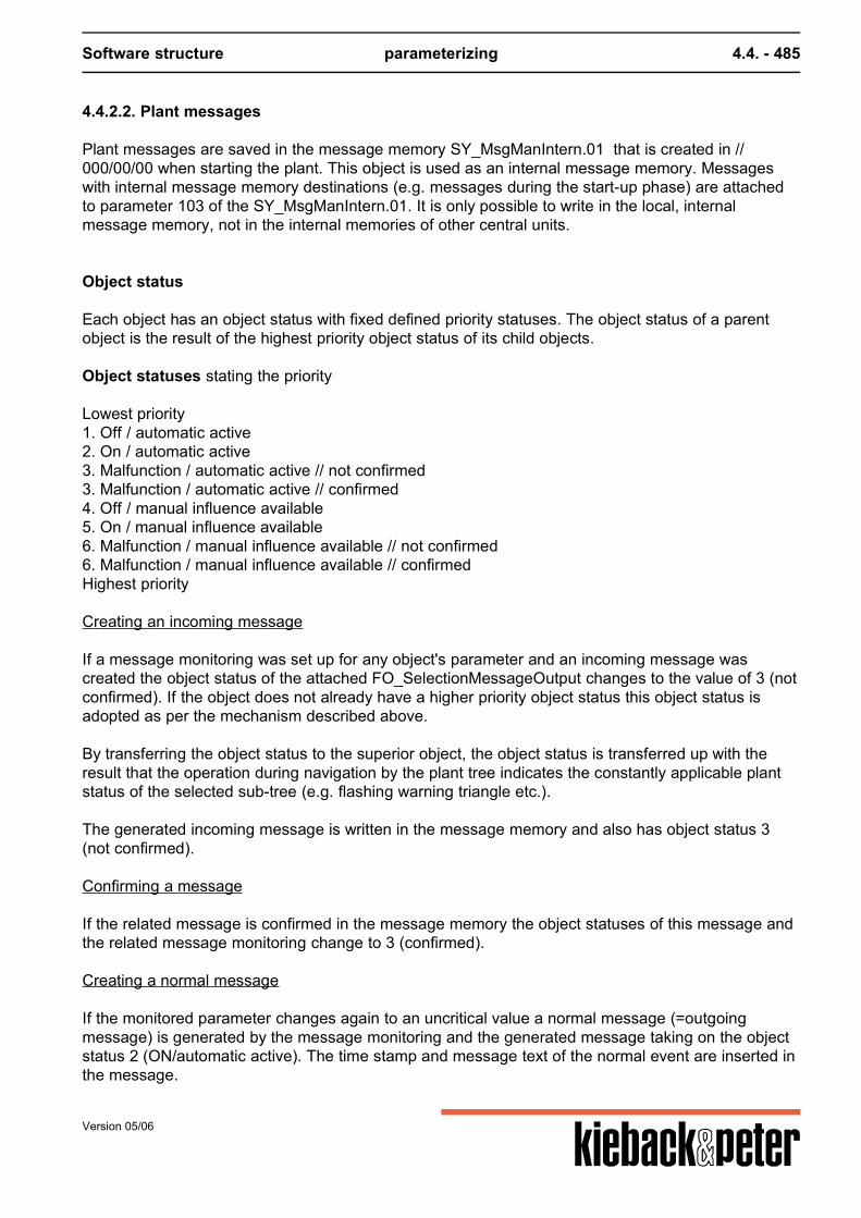
Software structure parameterizing 4.4. - 485
4.4.2.2. Plant messages
Plant messages are saved in the message memory SY_MsgManIntern.01 that is created in //000/00/00 when starting the plant. This object is used as an internal message memory. Messageswith internal message memory destinations (e.g. messages during the start-up phase) are attachedto parameter 103 of the SY_MsgManIntern.01. It is only possible to write in the local, internalmessage memory, not in the internal memories of other central units.
Object status
Each object has an object status with fixed defined priority statuses. The object status of a parentobject is the result of the highest priority object status of its child objects. Object statuses stating the priority Lowest priority1. Off / automatic active2. On / automatic active3. Malfunction / automatic active // not confirmed3. Malfunction / automatic active // confirmed4. Off / manual influence available5. On / manual influence available6. Malfunction / manual influence available // not confirmed6. Malfunction / manual influence available // confirmedHighest priority Creating an incoming message If a message monitoring was set up for any object's parameter and an incoming message wascreated the object status of the attached FO_SelectionMessageOutput changes to the value of 3 (notconfirmed). If the object does not already have a higher priority object status this object status isadopted as per the mechanism described above. By transferring the object status to the superior object, the object status is transferred up with theresult that the operation during navigation by the plant tree indicates the constantly applicable plantstatus of the selected sub-tree (e.g. flashing warning triangle etc.). The generated incoming message is written in the message memory and also has object status 3(not confirmed). Confirming a message If the related message is confirmed in the message memory the object statuses of this message andthe related message monitoring change to 3 (confirmed). Creating a normal message If the monitored parameter changes again to an uncritical value a normal message (=outgoingmessage) is generated by the message monitoring and the generated message taking on the objectstatus 2 (ON/automatic active). The time stamp and message text of the normal event are inserted inthe message.
Version 05/06
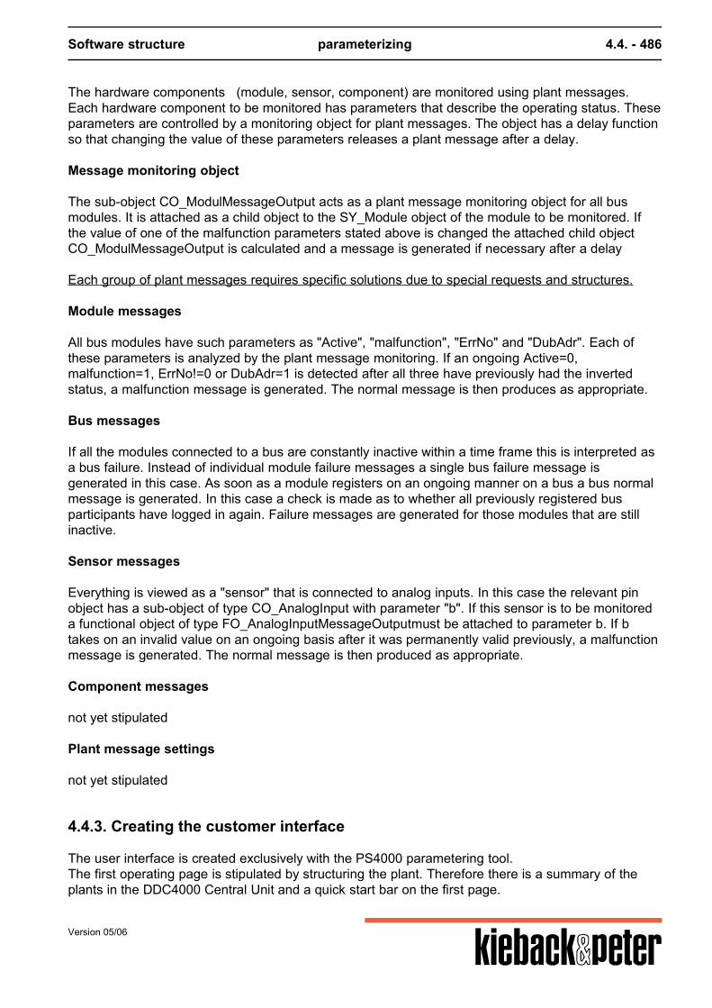
Software structure parameterizing 4.4. - 486
The hardware components (module, sensor, component) are monitored using plant messages.Each hardware component to be monitored has parameters that describe the operating status. Theseparameters are controlled by a monitoring object for plant messages. The object has a delay functionso that changing the value of these parameters releases a plant message after a delay. Message monitoring object The sub-object CO_ModulMessageOutput acts as a plant message monitoring object for all busmodules. It is attached as a child object to the SY_Module object of the module to be monitored. Ifthe value of one of the malfunction parameters stated above is changed the attached child objectCO_ModulMessageOutput is calculated and a message is generated if necessary after a delay Each group of plant messages requires specific solutions due to special requests and structures. Module messages All bus modules have such parameters as "Active", "malfunction", "ErrNo" and "DubAdr". Each ofthese parameters is analyzed by the plant message monitoring. If an ongoing Active=0,malfunction=1, ErrNo!=0 or DubAdr=1 is detected after all three have previously had the invertedstatus, a malfunction message is generated. The normal message is then produces as appropriate. Bus messages If all the modules connected to a bus are constantly inactive within a time frame this is interpreted asa bus failure. Instead of individual module failure messages a single bus failure message isgenerated in this case. As soon as a module registers on an ongoing manner on a bus a bus normalmessage is generated. In this case a check is made as to whether all previously registered busparticipants have logged in again. Failure messages are generated for those modules that are stillinactive. Sensor messages Everything is viewed as a "sensor" that is connected to analog inputs. In this case the relevant pinobject has a sub-object of type CO_AnalogInput with parameter "b". If this sensor is to be monitoreda functional object of type FO_AnalogInputMessageOutputmust be attached to parameter b. If btakes on an invalid value on an ongoing basis after it was permanently valid previously, a malfunctionmessage is generated. The normal message is then produced as appropriate. Component messages not yet stipulated Plant message settings not yet stipulated
4.4.3. Creating the customer interface
The user interface is created exclusively with the PS4000 parametering tool.The first operating page is stipulated by structuring the plant. Therefore there is a summary of theplants in the DDC4000 Central Unit and a quick start bar on the first page.
Version 05/06
Software structure parameterizing 4.4. - 487
Depiction of opening page withsummary of all plants and thequick start bar
Groups may be located within the plants. The "switch" page is given the title that the group has in theDDC Central Unit. All binary information that have a tick under the "visualization in DDC" commandis found under this title, e.g. "supply air fan". Switch groups or LEDs are inserted correspondingly.
The formation of the "values" page is similar. Here all the parameters that are displayed behind eachother must also receive a command "visualizing in DDC". As the depiction is set in the DDC Central Unit a change to the visualization regulations can only bemade via the tool. The page settings are generated here and stored as a data backup in the DDCCentral Unit. It is not possible to generate these pages in the DDC.
Version 05/06
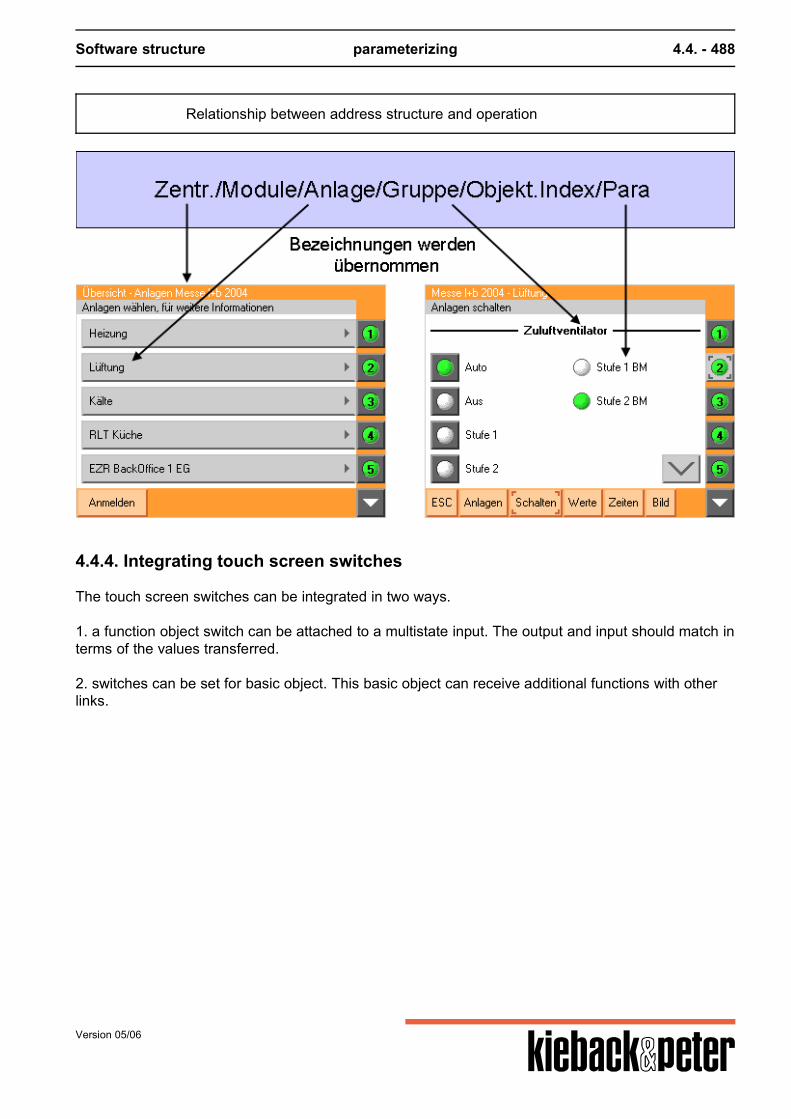
Software structure parameterizing 4.4. - 488
Relationship between address structure and operation
4.4.4. Integrating touch screen switches
The touch screen switches can be integrated in two ways. 1. a function object switch can be attached to a multistate input. The output and input should match interms of the values transferred. 2. switches can be set for basic object. This basic object can receive additional functions with otherlinks.
Version 05/06
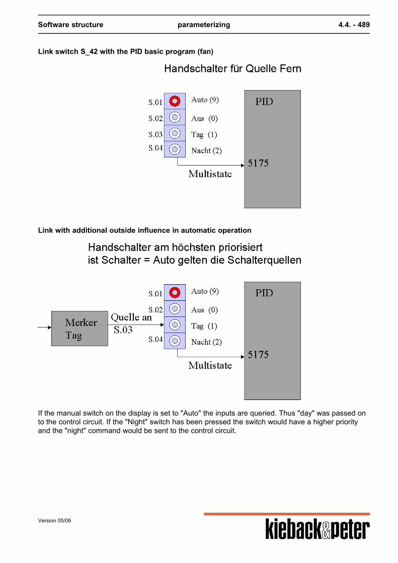
Software structure parameterizing 4.4. - 489
Link switch S_42 with the PID basic program (fan)
Link with additional outside influence in automatic operation
If the manual switch on the display is set to "Auto" the inputs are queried. Thus "day" was passed onto the control circuit. If the "Night" switch has been pressed the switch would have a higher priorityand the "night" command would be sent to the control circuit.
Version 05/06
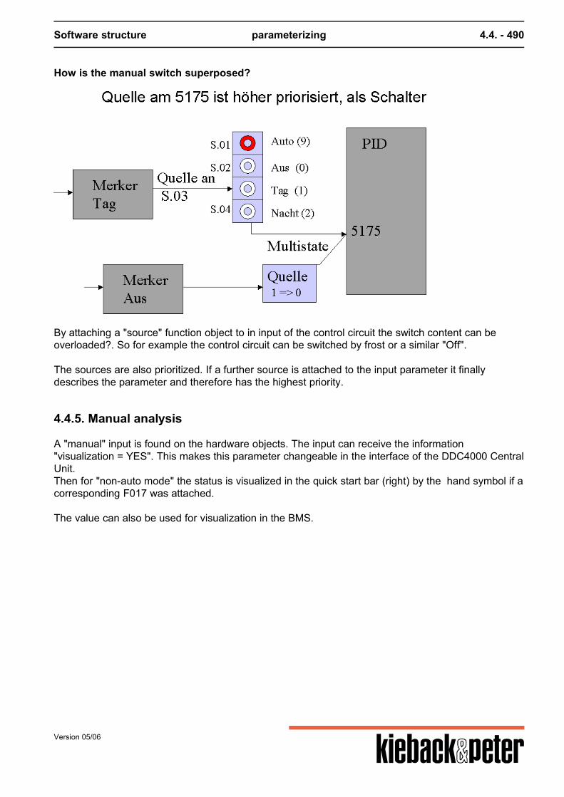
Software structure parameterizing 4.4. - 490
How is the manual switch superposed?
By attaching a "source" function object to in input of the control circuit the switch content can beoverloaded?. So for example the control circuit can be switched by frost or a similar "Off". The sources are also prioritized. If a further source is attached to the input parameter it finallydescribes the parameter and therefore has the highest priority.
4.4.5. Manual analysis
A "manual" input is found on the hardware objects. The input can receive the information"visualization = YES". This makes this parameter changeable in the interface of the DDC4000 CentralUnit.Then for "non-auto mode" the status is visualized in the quick start bar (right) by the hand symbol if acorresponding F017 was attached. The value can also be used for visualization in the BMS.
Version 05/06
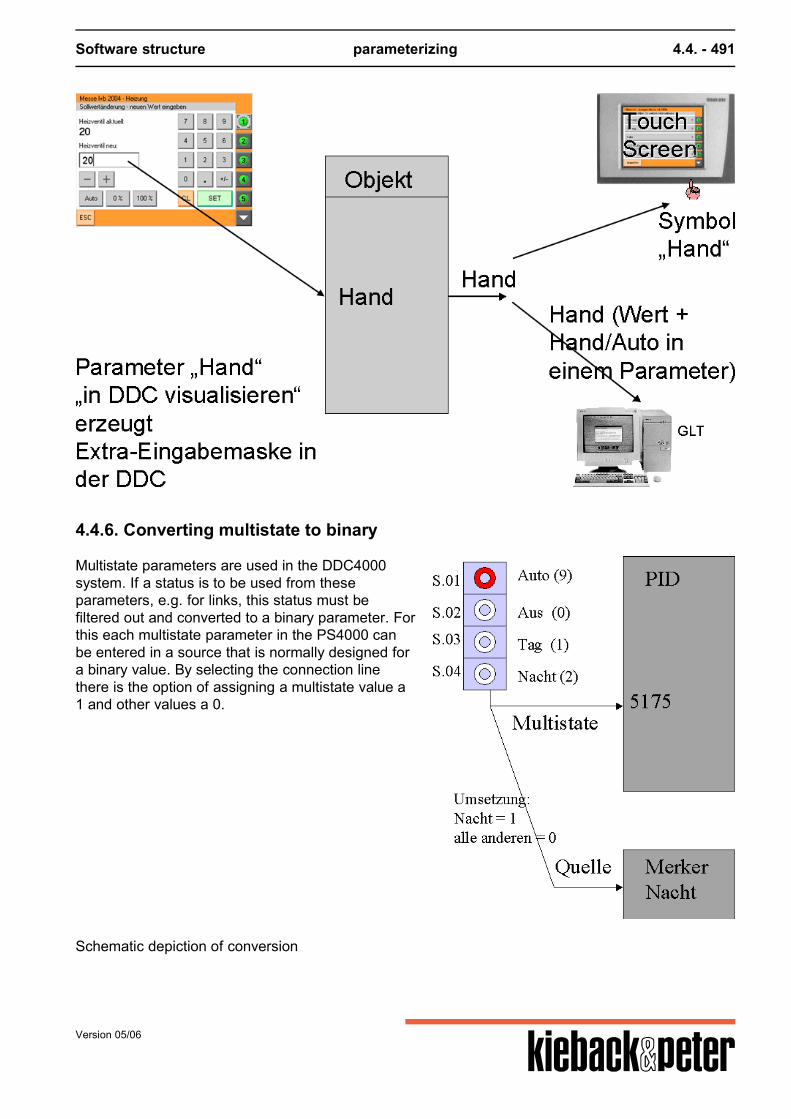
Software structure parameterizing 4.4. - 491
4.4.6. Converting multistate to binary
Multistate parameters are used in the DDC4000system. If a status is to be used from theseparameters, e.g. for links, this status must befiltered out and converted to a binary parameter. Forthis each multistate parameter in the PS4000 canbe entered in a source that is normally designed fora binary value. By selecting the connection linethere is the option of assigning a multistate value a1 and other values a 0.
Schematic depiction of conversion
Version 05/06
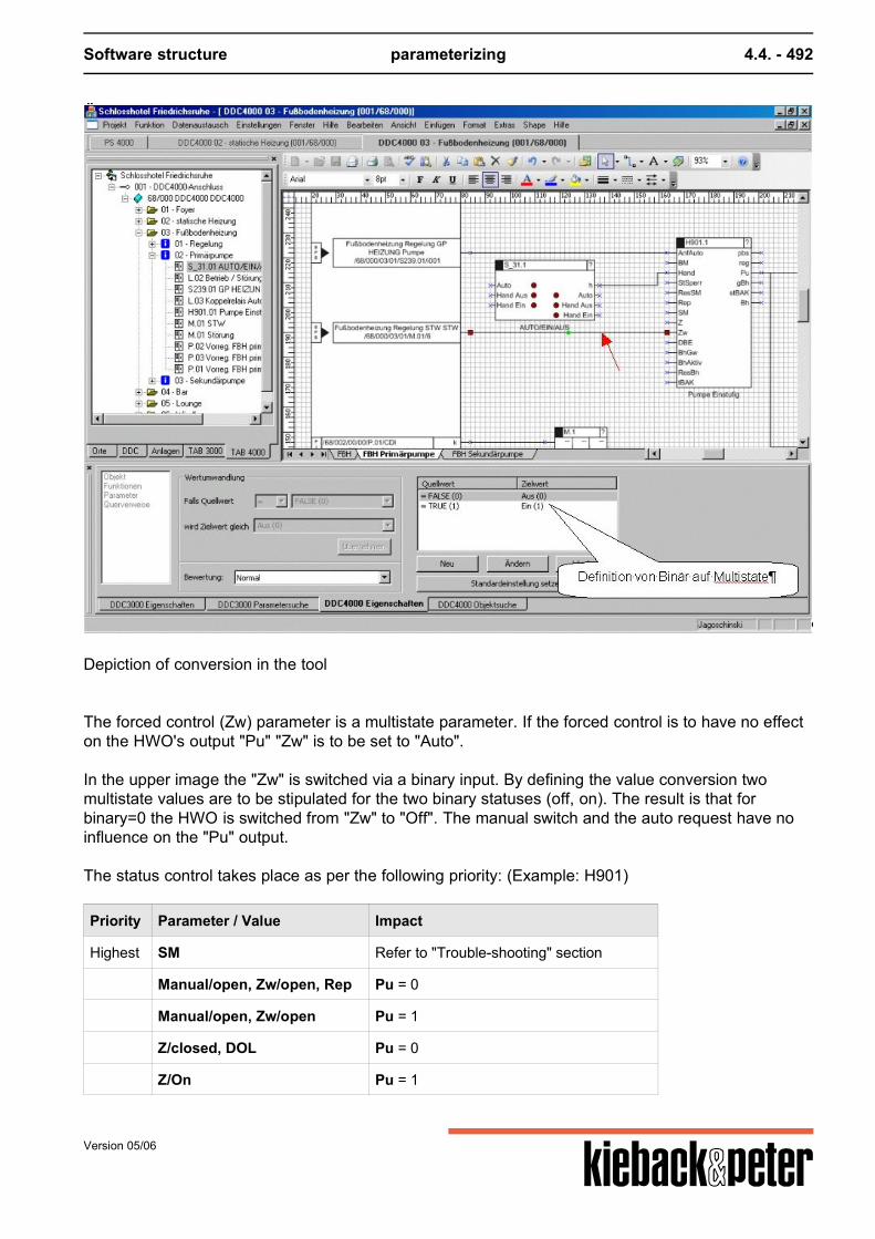
Software structure parameterizing 4.4. - 492
Depiction of conversion in the tool The forced control (Zw) parameter is a multistate parameter. If the forced control is to have no effecton the HWO's output "Pu" "Zw" is to be set to "Auto". In the upper image the "Zw" is switched via a binary input. By defining the value conversion twomultistate values are to be stipulated for the two binary statuses (off, on). The result is that forbinary=0 the HWO is switched from "Zw" to "Off". The manual switch and the auto request have noinfluence on the "Pu" output. The status control takes place as per the following priority: (Example: H901)
Priority Parameter / Value Impact
Highest SM Refer to "Trouble-shooting" section
Manual/open, Zw/open, Rep Pu = 0
Manual/open, Zw/open Pu = 1
Z/closed, DOL Pu = 0
Z/On Pu = 1
Version 05/06
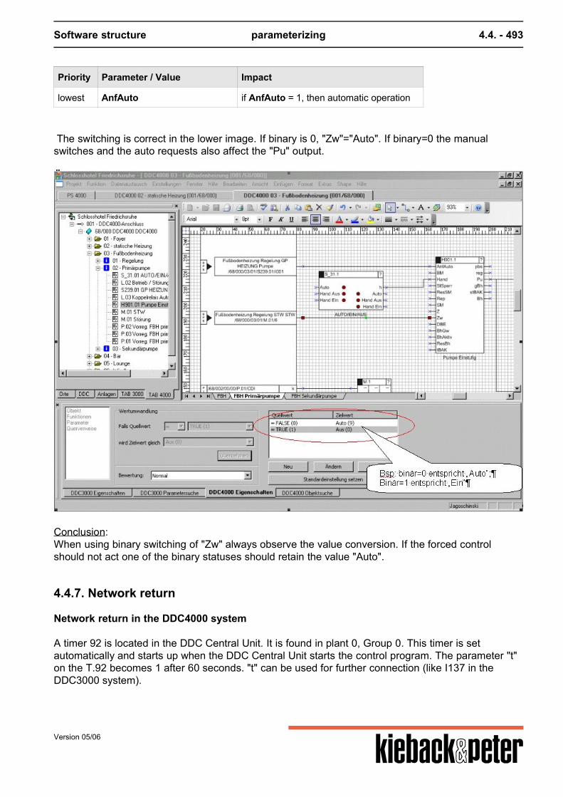
Software structure parameterizing 4.4. - 493
Priority Parameter / Value Impact
lowest AnfAuto if AnfAuto = 1, then automatic operation
The switching is correct in the lower image. If binary is 0, "Zw"="Auto". If binary=0 the manualswitches and the auto requests also affect the "Pu" output.
Conclusion:When using binary switching of "Zw" always observe the value conversion. If the forced controlshould not act one of the binary statuses should retain the value "Auto".
4.4.7. Network return
Network return in the DDC4000 system
A timer 92 is located in the DDC Central Unit. It is found in plant 0, Group 0. This timer is setautomatically and starts up when the DDC Central Unit starts the control program. The parameter "t"on the T.92 becomes 1 after 60 seconds. "t" can be used for further connection (like I137 in theDDC3000 system).
Version 05/06
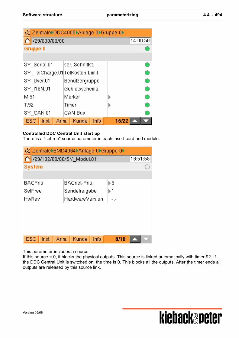
Software structure parameterizing 4.4. - 494
Controlled DDC Central Unit start upThere is a "setfree" source parameter in each insert card and module.
This parameter includes a source.If this source = 0, it blocks the physical outputs. This source is linked automatically with timer 92. Ifthe DDC Central Unit is switched on, the time is 0. This blocks all the outputs. After the timer ends alloutputs are released by this source link.
Version 05/06
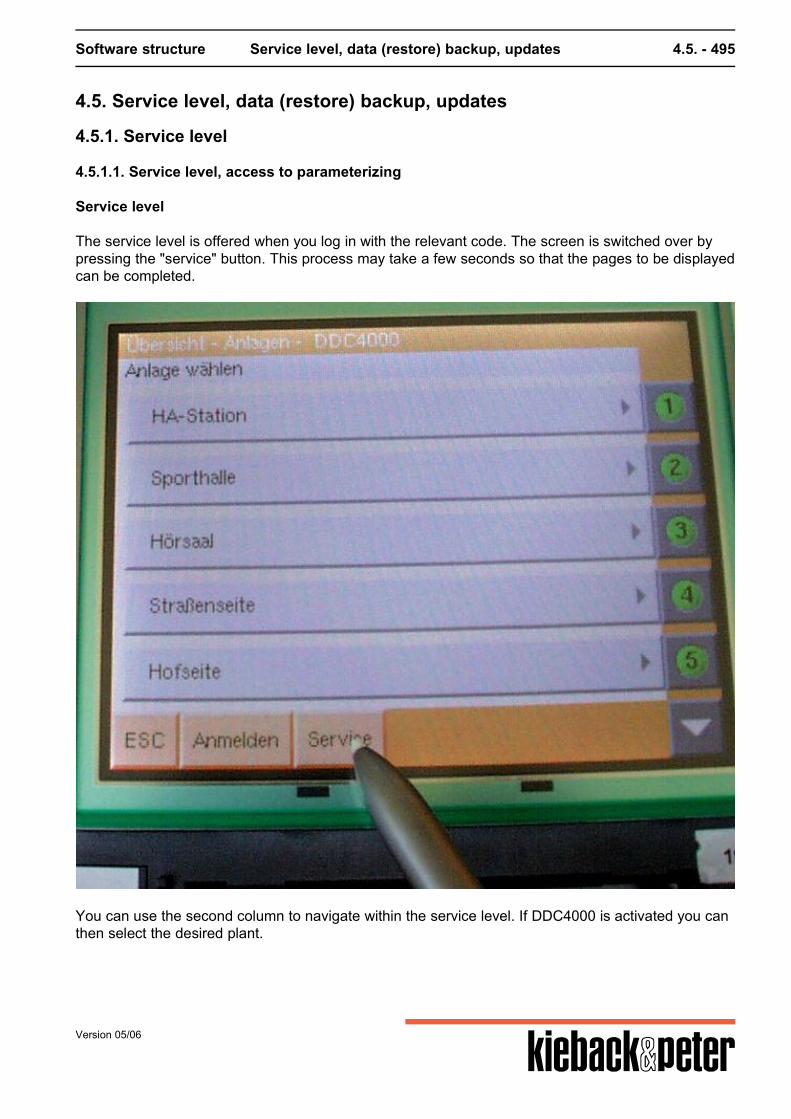
Software structure Service level, data (restore) backup, updates 4.5. - 495
4.5. Service level, data (restore) backup, updates
4.5.1. Service level
4.5.1.1. Service level, access to parameterizing
Service level
The service level is offered when you log in with the relevant code. The screen is switched over bypressing the "service" button. This process may take a few seconds so that the pages to be displayedcan be completed.
You can use the second column to navigate within the service level. If DDC4000 is activated you canthen select the desired plant.
Version 05/06
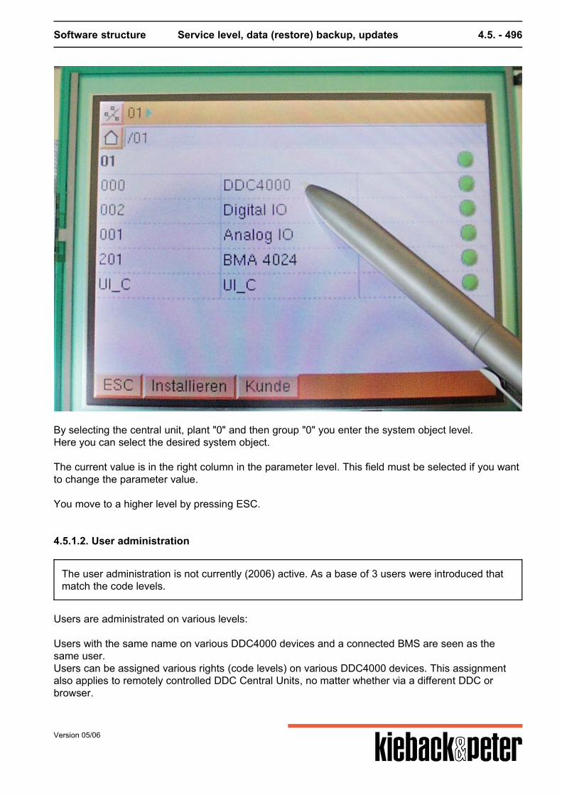
Software structure Service level, data (restore) backup, updates 4.5. - 496
By selecting the central unit, plant "0" and then group "0" you enter the system object level.Here you can select the desired system object. The current value is in the right column in the parameter level. This field must be selected if you wantto change the parameter value. You move to a higher level by pressing ESC.
4.5.1.2. User administration
The user administration is not currently (2006) active. As a base of 3 users were introduced thatmatch the code levels.
Users are administrated on various levels: Users with the same name on various DDC4000 devices and a connected BMS are seen as thesame user.Users can be assigned various rights (code levels) on various DDC4000 devices. This assignmentalso applies to remotely controlled DDC Central Units, no matter whether via a different DDC orbrowser.
Version 05/06
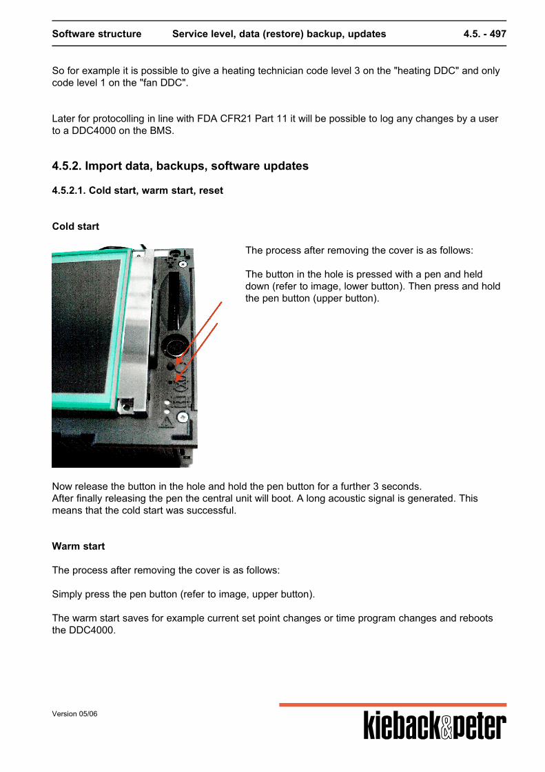
Software structure Service level, data (restore) backup, updates 4.5. - 497
So for example it is possible to give a heating technician code level 3 on the "heating DDC" and onlycode level 1 on the "fan DDC". Later for protocolling in line with FDA CFR21 Part 11 it will be possible to log any changes by a userto a DDC4000 on the BMS.
4.5.2. Import data, backups, software updates
4.5.2.1. Cold start, warm start, reset
Cold start
The process after removing the cover is as follows: The button in the hole is pressed with a pen and helddown (refer to image, lower button). Then press and holdthe pen button (upper button).
Now release the button in the hole and hold the pen button for a further 3 seconds.After finally releasing the pen the central unit will boot. A long acoustic signal is generated. Thismeans that the cold start was successful.
Warm start
The process after removing the cover is as follows: Simply press the pen button (refer to image, upper button). The warm start saves for example current set point changes or time program changes and rebootsthe DDC4000.
Version 05/06
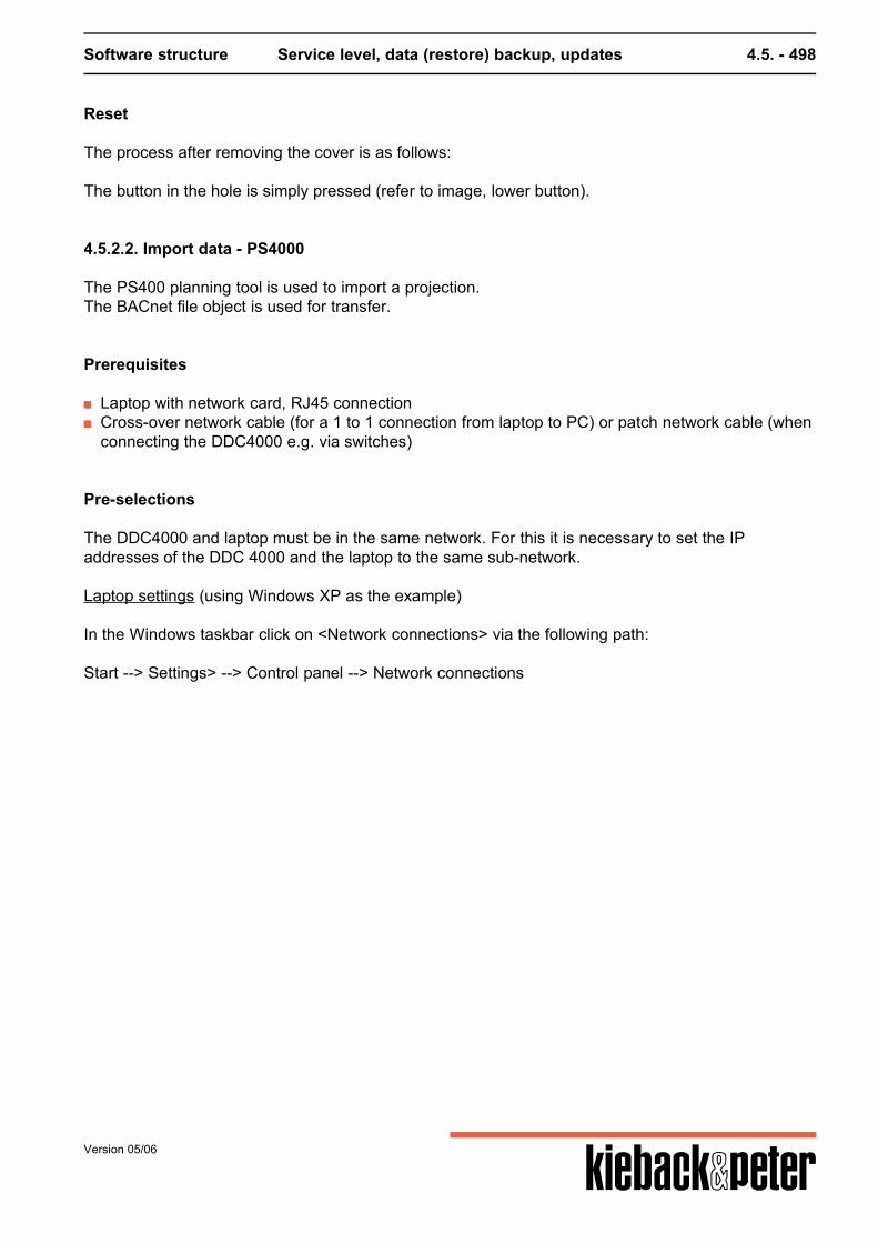
Software structure Service level, data (restore) backup, updates 4.5. - 498
Reset
The process after removing the cover is as follows: The button in the hole is simply pressed (refer to image, lower button).
4.5.2.2. Import data - PS4000
The PS400 planning tool is used to import a projection.The BACnet file object is used for transfer.
Prerequisites
Laptop with network card, RJ45 connection Cross-over network cable (for a 1 to 1 connection from laptop to PC) or patch network cable (when
connecting the DDC4000 e.g. via switches)
Pre-selections
The DDC4000 and laptop must be in the same network. For this it is necessary to set the IPaddresses of the DDC 4000 and the laptop to the same sub-network. Laptop settings (using Windows XP as the example) In the Windows taskbar click on <Network connections> via the following path: Start --> Settings> --> Control panel --> Network connections
Version 05/06
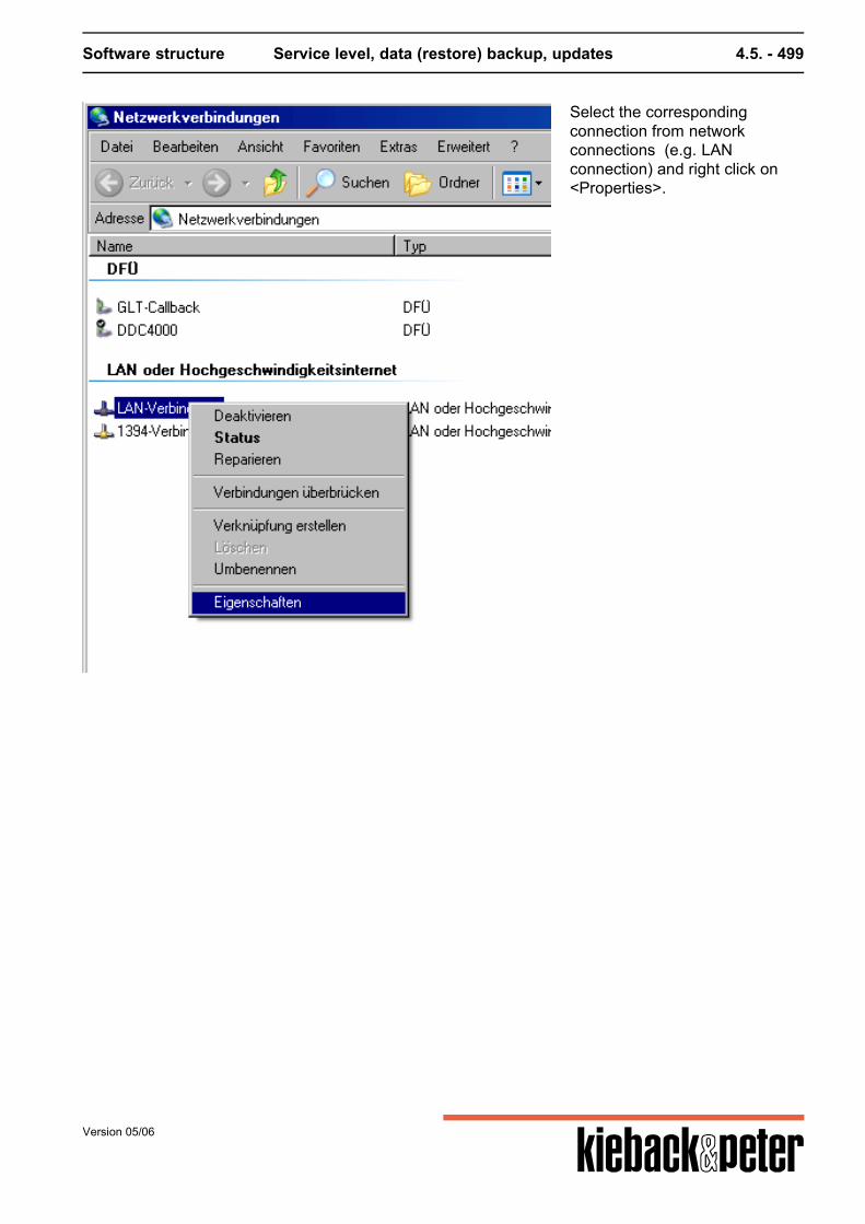
Software structure Service level, data (restore) backup, updates 4.5. - 499
Select the correspondingconnection from networkconnections (e.g. LANconnection) and right click on<Properties>.
Version 05/06
Software structure Service level, data (restore) backup, updates 4.5. - 500
In the properties windowdisplayed click on the <Internetprotocol (TCP/IP)> elementunder <General> and click onproperties.
Version 05/06
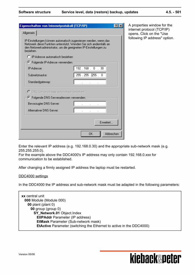
Software structure Service level, data (restore) backup, updates 4.5. - 501
A properties window for theinternet protocol (TCP/IP)opens. Click on the "Usefollowing IP address" option.
Enter the relevant IP address (e.g. 192.168.0.30) and the appropriate sub-network mask (e.g.255.255.255.0).For the example above the DDC4000's IP address may only contain 192.168.0.xxx forcommunication to be established. After changing a firmly assigned IP address the laptop must be restarted.
DDC4000 settings In the DDC4000 the IP address and sub-network mask must be adapted in the following parameters:
xx central unit 000 Module (Module 000) 00 plant (plant 0) 00 group (group 0) SY_Network.01 Object.Index EtIPAddr Parameter (IP address) EtMask Parameter (Sub-network mask) EtActive Parameter (switching the Ethernet to active in the DDC4000)
Version 05/06

Software structure Service level, data (restore) backup, updates 4.5. - 502
The sub-network mask must be the same as in the laptop. The IP address must not be the same asin the laptop but must match the sub-network mask. The Ethernet must still be switched on via the<EtActive> parameter. Now it is possible to access the DDC4000 from the laptop via Explorer. To do so enter theDDC4000's IP address in the address field in Explorer. If it is not possible to access the DDC4000this may be due to the "Java 2 Runtime Environment" software not being installed on the laptop. Thissoftware must be installed and can be downloaded from the intranet from the following path:Documents --> Technical --> DDC4000 system --> Network technologyIt can also be found on the Internet by entering the search term "j2re".
Please note: Access from the browser to the DDC4000 is not required for importing data to the DDC.
Version 05/06
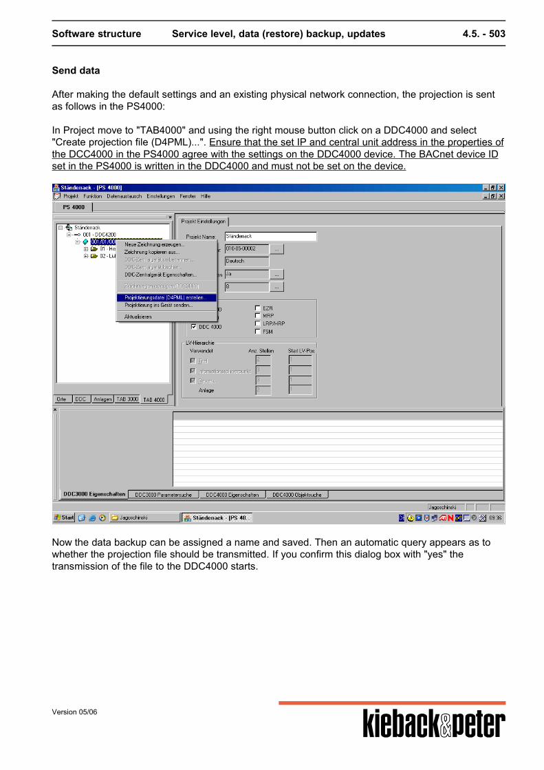
Software structure Service level, data (restore) backup, updates 4.5. - 503
Send data
After making the default settings and an existing physical network connection, the projection is sentas follows in the PS4000: In Project move to "TAB4000" and using the right mouse button click on a DDC4000 and select"Create projection file (D4PML)...". Ensure that the set IP and central unit address in the properties ofthe DCC4000 in the PS4000 agree with the settings on the DDC4000 device. The BACnet device IDset in the PS4000 is written in the DDC4000 and must not be set on the device.
Now the data backup can be assigned a name and saved. Then an automatic query appears as towhether the projection file should be transmitted. If you confirm this dialog box with "yes" thetransmission of the file to the DDC4000 starts.
Version 05/06
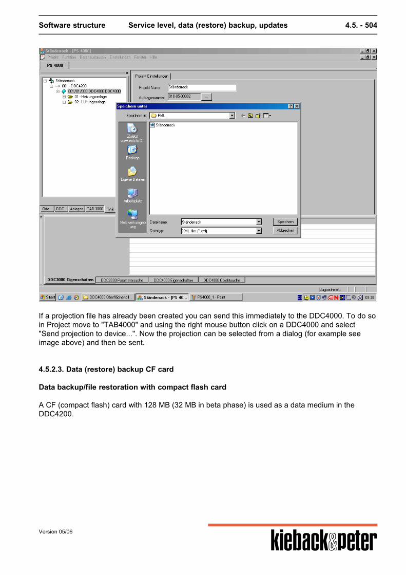
Software structure Service level, data (restore) backup, updates 4.5. - 504
If a projection file has already been created you can send this immediately to the DDC4000. To do soin Project move to "TAB4000" and using the right mouse button click on a DDC4000 and select"Send projection to device...". Now the projection can be selected from a dialog (for example seeimage above) and then be sent.
4.5.2.3. Data (restore) backup CF card
Data backup/file restoration with compact flash card
A CF (compact flash) card with 128 MB (32 MB in beta phase) is used as a data medium in theDDC4200.
Version 05/06
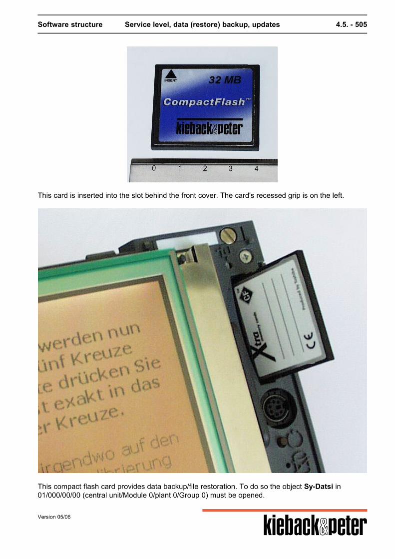
Software structure Service level, data (restore) backup, updates 4.5. - 505
This card is inserted into the slot behind the front cover. The card's recessed grip is on the left.
This compact flash card provides data backup/file restoration. To do so the object Sy-Datsi in01/000/00/00 (central unit/Module 0/plant 0/Group 0) must be opened.
Version 05/06
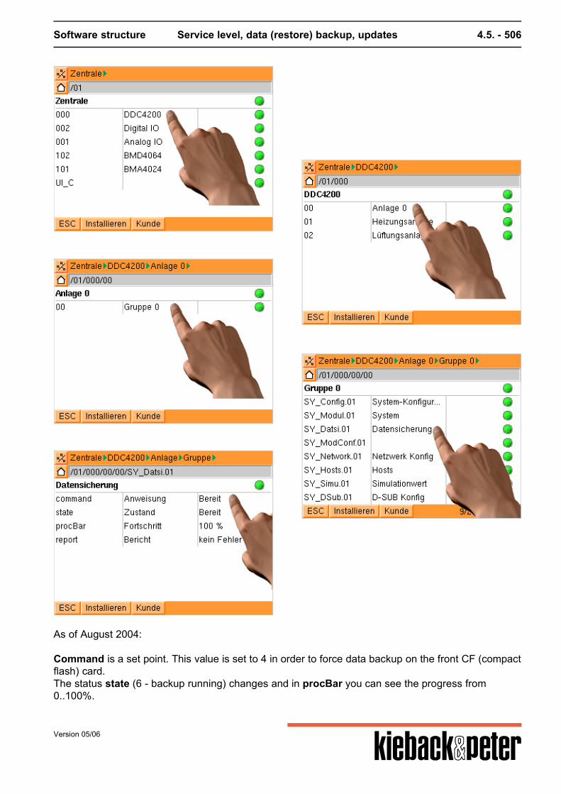
Software structure Service level, data (restore) backup, updates 4.5. - 506
As of August 2004: Command is a set point. This value is set to 4 in order to force data backup on the front CF (compactflash) card.The status state (6 - backup running) changes and in procBar you can see the progress from0..100%.
Version 05/06
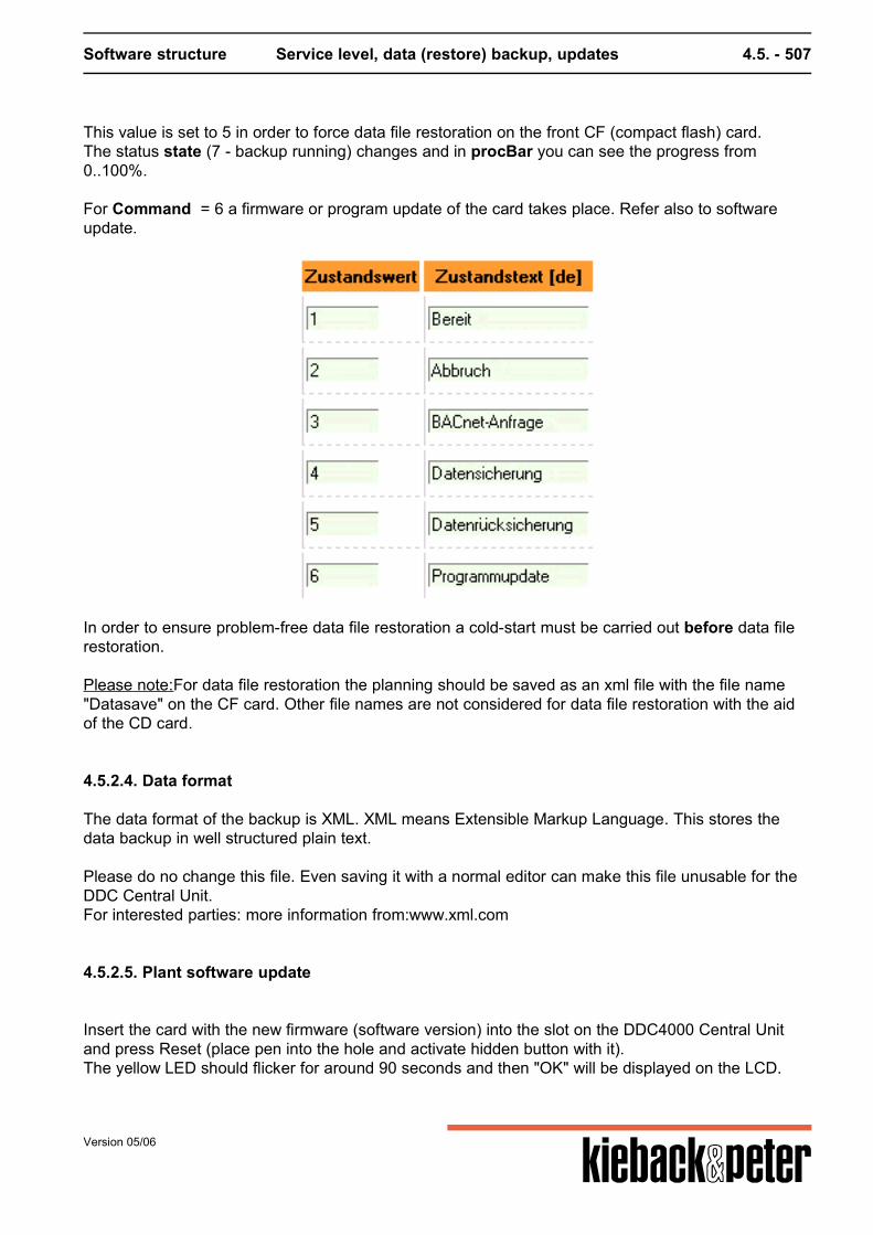
Software structure Service level, data (restore) backup, updates 4.5. - 507
This value is set to 5 in order to force data file restoration on the front CF (compact flash) card.The status state (7 - backup running) changes and in procBar you can see the progress from0..100%. For Command = 6 a firmware or program update of the card takes place. Refer also to softwareupdate.
In order to ensure problem-free data file restoration a cold-start must be carried out before data filerestoration. Please note:For data file restoration the planning should be saved as an xml file with the file name"Datasave" on the CF card. Other file names are not considered for data file restoration with the aidof the CD card.
4.5.2.4. Data format
The data format of the backup is XML. XML means Extensible Markup Language. This stores thedata backup in well structured plain text. Please do no change this file. Even saving it with a normal editor can make this file unusable for theDDC Central Unit.For interested parties: more information from:www.xml.com
4.5.2.5. Plant software update
Insert the card with the new firmware (software version) into the slot on the DDC4000 Central Unitand press Reset (place pen into the hole and activate hidden button with it).The yellow LED should flicker for around 90 seconds and then "OK" will be displayed on the LCD.
Version 05/06
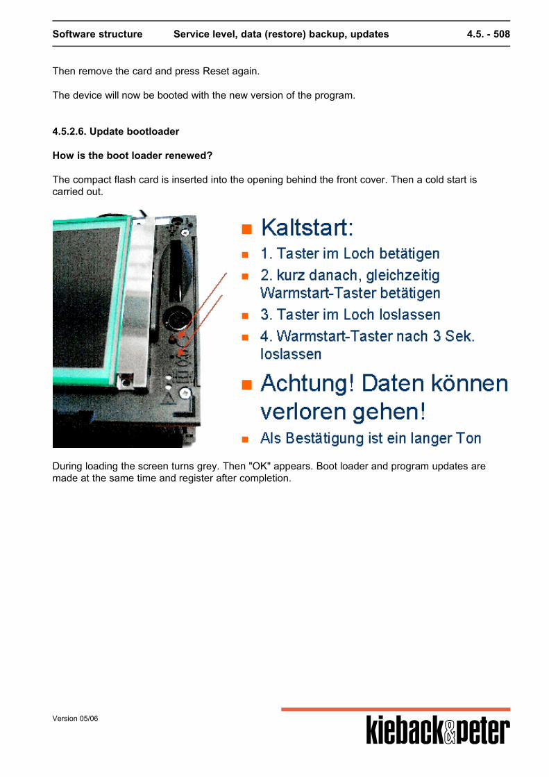
Software structure Service level, data (restore) backup, updates 4.5. - 508
Then remove the card and press Reset again.
The device will now be booted with the new version of the program.
4.5.2.6. Update bootloader
How is the boot loader renewed?
The compact flash card is inserted into the opening behind the front cover. Then a cold start iscarried out.
During loading the screen turns grey. Then "OK" appears. Boot loader and program updates aremade at the same time and register after completion.
Version 05/06
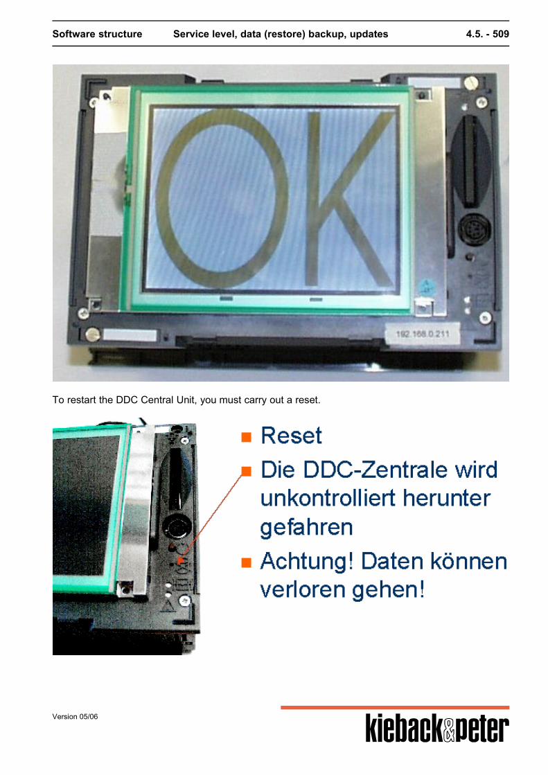
Software structure Service level, data (restore) backup, updates 4.5. - 509
To restart the DDC Central Unit, you must carry out a reset.
Version 05/06


![Documentation EK110x, EK15xx - Directory contents of ... · PDF fileDocumentation EK110x, EK15xx EtherCAT Bus Coupler 3.6 2017-10-05 ... 22] - EtherCAT Bus Coupler Connection Fiber](https://img.pdfslide.us/doc/110x75/5ab04dc27f8b9a190d8e74c9/documentation-ek110x-ek15xx-directory-contents-of-ek110x-ek15xx-ethercat.jpg)