Embed Size (px)
Citation preview

Document: V 1.00 / Document No.: 105727 │ Date 16.05.2018
Installation manual V 1.00 EVLunic
Charging Station
Translation of the original manual

table of contents
Installation manual V 1.00 Document: V 1.00 / Document No.: 105727 │ Date 16.05.2018 │2
table of contents
1 Introduction................................................................................................................................................. 4 1.1 Representation of safety instructions .............................................................................................. 5 1.2 Purpose of the document ................................................................................................................ 6 1.3 Requirements .................................................................................................................................. 6 1.4 Intended use ................................................................................................................................... 6 1.5 Guarantee ....................................................................................................................................... 7 1.6 Notes on this document .................................................................................................................. 8
1.6.1 Contents of the document ................................................................................................................ 8 1.6.2 Not contained in this document ........................................................................................................ 8
1.7 Further documentation .................................................................................................................... 9
2 Safety notes ............................................................................................................................................. 10
3 Scope of delivery ...................................................................................................................................... 11
4 Description of the charging station ........................................................................................................... 14 4.1 Front view ..................................................................................................................................... 14 4.2 Rear view ...................................................................................................................................... 15 4.3 Top view ........................................................................................................................................ 15 4.4 Type plate ..................................................................................................................................... 16 4.5 Overview of variants ...................................................................................................................... 17 4.6 Options .......................................................................................................................................... 18
4.6.1 RFID ...............................................................................................................................................18 4.6.2 Key switch ......................................................................................................................................19 4.6.3 GSM (only EVLunic Pro M) ............................................................................................................19
5 Displays and operating elements ............................................................................................................. 20 5.1 LED bar ......................................................................................................................................... 20 5.2 Display (optional) .......................................................................................................................... 20
6 Mounting and installation instructions ....................................................................................................... 21 6.1 General criteria for the site selection ............................................................................................. 23 6.2 Space requirements ...................................................................................................................... 24 6.3 Required tools ............................................................................................................................... 24 6.4 Mounting the charging station ....................................................................................................... 25
7 Connections and wiring ............................................................................................................................ 29 7.1 Connection overview ..................................................................................................................... 29 7.2 Required tools ............................................................................................................................... 30 7.3 Power supply ................................................................................................................................ 30
7.3.1 Cable installation ............................................................................................................................31 7.3.2 Connecting the voltage supply .......................................................................................................32 7.3.3 Electrical connection to special systems of AC power supply .......................................................34
7.4 Enable input X1 (except EVLunic B) ............................................................................................. 35 7.4.1 Connection diagram .......................................................................................................................35
7.5 Switch contact output X2 (except EVLunic B) ............................................................................... 35

table of contents
Installation manual V 1.00 Document: V 1.00 / Document No.: 105727 │ Date 16.05.2018 │3
7.5.1 Connection diagram .......................................................................................................................36 7.5.2 Connection example .......................................................................................................................37
7.6 Ethernet connection X3 and X4 (optional) ..................................................................................... 37
8 Configuration ............................................................................................................................................ 40 8.1 DIP switch settings ........................................................................................................................ 40 8.2 Prepare GSM connection (optional) .............................................................................................. 45
8.2.1 Inserting the SIM card ....................................................................................................................45 8.2.2 Removing the SIM card ..................................................................................................................46
9 Commissioning ......................................................................................................................................... 47 9.1 Activating/deactivating commissioning mode ................................................................................ 48 9.2 Perform safety checks ................................................................................................................... 49 9.3 Mount covers ................................................................................................................................ 49 9.4 Attach seal .................................................................................................................................... 51
10 Maintenance ............................................................................................................................................. 52 10.1 Replacing the fuse ........................................................................................................................ 52 10.2 Troubleshooting ............................................................................................................................ 52 10.3 Software update ............................................................................................................................ 53 10.4 Replace the SIM Card ................................................................................................................... 53
11 Disposal ................................................................................................................................................... 54 11.1 Disposal of the charging station .................................................................................................... 54
12 Technical data .......................................................................................................................................... 55 12.1 General ......................................................................................................................................... 55 12.2 Power supply ................................................................................................................................ 55 12.3 Cable / Socket ............................................................................................................................... 56 12.4 Ambient conditions ........................................................................................................................ 56 12.5 Interfaces ...................................................................................................................................... 57 12.6 MID specific data........................................................................................................................... 58 12.7 Dimensions ................................................................................................................................... 59
13 EU Directives and Standards ................................................................................................................... 62
14 Declaration of conformity .......................................................................................................................... 63

Introduction
Installation manual V 1.00 Document: V 1.00 / Document No.: 105727 │ Date 16.05.2018 │4
1 Introduction
This manual is valid for EVLunic B, B+, Pro S and Pro M.
The pictured devices used in this manual are visual examples. The figures and explanations contained in this manual refer to a typical device design. The devices used by you may differ in their appearance. We recommend always keeping the charging station updated to the most recent software version, as this contains functional enhancements and product improvements.

Introduction
Installation manual V 1.00 Document: V 1.00 / Document No.: 105727 │ Date 16.05.2018 │5
1.1 Representation of safety instructions
At various points in this manual, you will see notes and precautionary warnings regarding possible hazards. The symbols used have the following meaning:
Danger Indicates an imminently hazardous situation, which will result in death or serious bodily injury if the corresponding precautions are not taken.
Warning Indicates a potentially hazardous situation, which can result in death or serious bodily injury if the corresponding precautions are not taken.
Caution Means that if the corresponding safety measures are not taken, a potentially hazardous situation can occur that may result in slight bodily injury.
Attention! Means that damage to property can occur if the corresponding safety measures are not taken.
ESD This symbol reminds you of the possible consequences of touching electrostatically sensitive components.
Note Identifies practical tips and useful information. No information that warns about potentially dangerous or harmful functions is contained.

Introduction
Installation manual V 1.00 Document: V 1.00 / Document No.: 105727 │ Date 16.05.2018 │6
1.2 Purpose of the document
This document describes the complete installation of EVLunic.
This document is an extension to the supplied manuals of EVLunic.
You must comply with all instructions and safety notes in the supplied manuals!
1.3 Requirements
This document contains information for persons with the following requirements:
Target group Required knowledge and abilities
Electrician
Person who, due to his or her special training, expertise and experience as well as knowledge of current standards, is able to assess the work performed and the possible hazards. Knowledge of: ■ current valid safety information, ■ the mode of operation of the charging station, ■ the displays and operating elements of the charging station, ■ basics of network technology, diagnostic options, ■ systematic fault analysis and rectification, ■ the setting options on the charging station.
1.4 Intended use
The charging station is intended for charging electric vehicles (such as electric cars). The connection of other devices (such as power tools) is not allowed.
The charging station is suitable for indoor and outdoor use. The charging station has to be installed vertically on a wall or on a floor-mounted column. The surface for the installation must be flat and suitably stable (e.g. brick wall, concrete wall). The respective national regulations must be observed with regard to the installation and connection of the charging station.
The intended use of the device always includes the compliance with the environmental conditions for which this device was developed.
The charging station has been developed, manufactured, tested and documented in accordance with the appropriate safety standards. If the instructions and safety instructions described for the intended use are observed, the product will normally not pose a risk to the health of persons or damage to property.
Not observing the safety instructions can result in risk of death, injuries and damage to the device! The device manufacturer assumes no liability for resulting claims!
Introduction
Installation manual V 1.00 Document: V 1.00 / Document No.: 105727 │ Date 16.05.2018 │7
1.5 Guarantee
Only the maintenance work expressly permitted by ABB may be performed. Any other manipulations to the device will also result in loss of warranty.
Warning – Danger due to electric shock and fire hazard! After opening the front part, product safety can no longer be guaranteed.
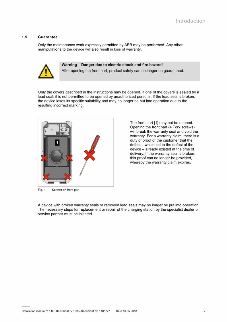
Only the covers described in the instructions may be opened. If one of the covers is sealed by a lead seal, it is not permitted to be opened by unauthorized persons. If the lead seal is broken, the device loses its specific suitability and may no longer be put into operation due to the resulting incorrect marking.
The front part [1] may not be opened. Opening the front part (4 Torx screws) will break the warranty seal and void the warranty. For a warranty claim, there is a duty of proof of the customer that the defect – which led to the defect of the device – already existed at the time of delivery. If the warranty seal is broken, this proof can no longer be provided, whereby the warranty claim expires.
Fig. 1: Screws on front part
A device with broken warranty seals or removed lead seals may no longer be put into operation. The necessary steps for replacement or repair of the charging station by the specialist dealer or service partner must be initiated.

Introduction
Installation manual V 1.00 Document: V 1.00 / Document No.: 105727 │ Date 16.05.2018 │8
1.6 Notes on this document
The manual is part of the product. It is to be retained over the entire life cycle of the product and should be forwarded to any subsequent owners or users of the product.
The instructions contained in this manual must be followed precisely. Failure to do so could result in the creation of potential sources of danger or the disabling of safety devices. Apart from the safety instructions given in this manual, the safety precautions and accident prevention measures appropriate to the situation in question must also be observed.
1.6.1 Contents of the document
■ Description of the charging station ■ Assembly of the charging station ■ Electrical installation of the charging station ■ Commissioning of the charging station ■ Maintenance of the charging station
1.6.2 Not contained in this document
■ Operation of the charging station ■ Troubleshooting

Introduction
Installation manual V 1.00 Document: V 1.00 / Document No.: 105727 │ Date 16.05.2018 │9
1.7 Further documentation
Manuals and additional information are available on the ABB website:
new.abb.com/ev-charging
Designation Target group
Operating Instructions ■ End customer ■ Electricians
Configuration manual EVLunic Pro M ■ End customer ■ Electricians
USB Configuration Guide ■ Programmer ■ Electricians ■ Service technicians
UDP Programmer's Guide ■ Programmer
FAQ ■ End customer ■ Electricians ■ Programmer

Safety notes
Installation manual V 1.00 Document: V 1.00 / Document No.: 105727 │ Date 16.05.2018 │10
2 Safety notes
Warning – Risk of electric shock and fire hazard! ■ Installation, commissioning, maintenance or retrofitting of the charging
station must be performed by correctly trained, qualified and authorized electricians1) who are fully responsible for the compliance with existing standards and installation regulations. – Please observe that an additional overvoltage protection can be required
by vehicles or national regulations. – Also observe that some countries or vehicle manufacturers may require
a different triggering characteristic of the fault-current circuit breaker (Type B).
■ Do not install or use a damaged device. ■ A damaged charging station must be taken out of commission and repaired
or replaced by a qualified and authorized electrician. ■ A repair of the charging station is not permitted and may only be carried out
by the manufacturer. ■ No unauthorized modifications and modifications may be made to the
charging station. ■ No markings (such as safety signs, warnings, wire markings ...) may be
removed from the charging station. ■ Never use faulty, worn-out or dirty charging connectors. ■ The connection of cable extensions to the charging station’s charging cable
is not permitted.
1) Persons who, due to their special training, expertise and experience as well as knowledge of current standards, are able to assess the work performed and the possible hazards.
Attention! – Possible damage to property! ■ When connecting and wiring the charging station, ensure that the connection
area is clean so that no foreign objects (wire residues, etc.) get inside the charging station.
■ If necessary, protective films may only be removed after connecting the cables.
■ Pull the charging cable out of the plug holder only by the plug and not by the cable.
■ The charging cable may not be not damaged mechanically (kinked, pinched or driven over) and the contact area is not allowed to come into contact with sources of heat, dirt or water.
■ Never clean the charging station with aggressive solvents and cleaning agents, abrasive materials, spray water (garden hose, high-pressure cleaner, etc.) or excessive pressure.

Scope of delivery
Installation manual V 1.00 Document: V 1.00 / Document No.: 105727 │ Date 16.05.2018 │11
3 Scope of delivery
The following parts are included in the scope of delivery:
Basic elements
Description B B+ / Pro S / Pro M
Charging station 1x 1x
Cable holder (for versions with charging cable) 1x 1x
Installation and configuration instructions 1x 1x
Operating Instructions 1x 1x
Drilling template 1x 1x
Keys for cylinder lock (optional) - 3x
RFID card (optional) - 1x

Scope of delivery
Installation manual V 1.00 Document: V 1.00 / Document No.: 105727 │ Date 16.05.2018 │12
Installation materials
Fig. 2: Installation materials
No Description B B+ / Pro S / Pro M
[1] Cable gland M32x1.5 (clamping area 10–21mm) - 1x
[2] Lock nut M32x1.5 1x 1x
[3] Cable gland M16x1.5 (clamping area 4–10mm) - 1x
[4] Cable gland M20 1x 1x
[5] Lock nut M16x1.5 - 1x
[6] Double-membrane seals M32 (clamping area 14–21mm) 1x 1x
[7] Double-membrane seals M20 (clamping area 7–12mm) - 1x
[8] Sealing cap for terminal cover - 1x
[9] Reduction insert M32/M20 1x 1x
[10] Sealing cap for connection panel cover - 1x

Scope of delivery
Installation manual V 1.00 Document: V 1.00 / Document No.: 105727 │ Date 16.05.2018 │13
Mounting set for wall installation
Fig. 3: Wall installation mounting set
No Description B B+ / Pro S / Pro M
[1] Hangar bolts M8x100 - 4x
[2] Nut ISO 10511 - M8 - 4x
[3] Washer ISO 7089 - 8.4 - 8x
[4] Anchors for M8; Fischer UXR-8 - 4x

Description of the charging station
Installation manual V 1.00 Document: V 1.00 / Document No.: 105727 │ Date 16.05.2018 │14
4 Description of the charging station
4.1 Front view
Fig. 4: Overview of charging station
[1] Housing cover [2a] RFID reader (optional)
[2b] Key-operated switch (optional) [3] LED bar
[4a] Permanently installed charging cable (optional) [4b] Charging socket with cover (optional)
[5] Holder for charging cable (optional) [6] Display (optional)
Note Depending on the design of the charging station, the charging socket or charging cable may deviate from the shape shown.

Description of the charging station
Installation manual V 1.00 Document: V 1.00 / Document No.: 105727 │ Date 16.05.2018 │15
4.2 Rear view
Fig. 5: Rear view
[1] Mounting holes [2] Flush-mounting cable insertion openings M32 (for control line or Ethernet)
[3] Flush-mounting cable inertion openings M20 (for control line or Ethernet)
4.3 Top view
Fig. 6: Top view
[1] Type plate [2] Surface-mounting cable insertion openings M32 (for supply line)
[3] Surface-mounting cable insertion openings M16 (for control line or Ethernet)
Description of the charging station
Installation manual V 1.00 Document: V 1.00 / Document No.: 105727 │ Date 16.05.2018 │16
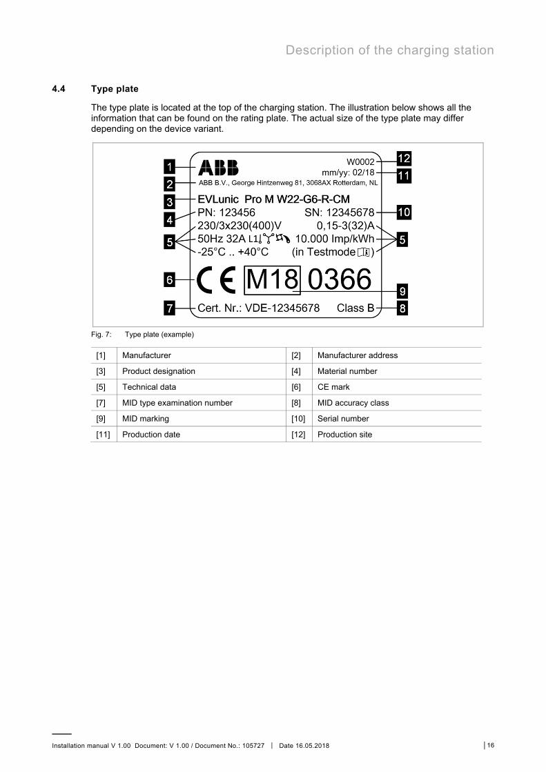
4.4 Type plate
The type plate is located at the top of the charging station. The illustration below shows all the information that can be found on the rating plate. The actual size of the type plate may differ depending on the device variant.
Fig. 7: Type plate (example)
[1] Manufacturer [2] Manufacturer address
[3] Product designation [4] Material number
[5] Technical data [6] CE mark
[7] MID type examination number [8] MID accuracy class
[9] MID marking [10] Serial number
[11] Production date [12] Production site

Description of the charging station
Installation manual V 1.00 Document: V 1.00 / Document No.: 105727 │ Date 16.05.2018 │17
4.5 Overview of variants
The type and features of the charging station can be determined by the product designation. The product designation is specified on the type plate.
Due to technical or legal restrictions, not all versions / options are available in all countries.
Example EVLunic Pro M W 22 - G 4 - R - C M
Product EVLunic Pro M W 22 - G 4 - R - C M Device series x B B B+ B+ Pro S Pro S Pro M Pro M Form factor x W W Output x 4.6 kW 4.6 11 kW 11 22 kW 22 Cable / Socket x Socket T Shutter S Type 1 P Type 2 G Cable type x No cable "" 4 m cable 4 6 m cable 6 Authorization x None "" RFID R Key switch K Communication x None "" Cellular (3G) C Energy meter / MID1) x None "" Energy meter (not calibrated) E
Calibratable energy meter (MID) M
1) MID: Measuring Instruments Directive

Description of the charging station
Installation manual V 1.00 Document: V 1.00 / Document No.: 105727 │ Date 16.05.2018 │18
Variants with energy meter / MID
Variants with the option "E" (energy meter, not calibrated) may be used for energy measurement and evaluation of self-energy consumption. Due to the lack of proof of accuracy, these devices must not be used billing energy.
Variants with the option "M" (calibratable energy meter) are authorized for the measurement of active energy for billing purposes (according to MID 2014/32/EU). These devices are specially marked on the type plate (MID approval). The associated type examination refers to the complete unit. The measurement of the transmitted energy takes place by means of transducers on all phases to be contacted. Further documents concerning MID (e.g. test mode) can be requested from ABB.
All variants deriving from the product designation are available with calibratable energy meter (MID). A list of possible variants is included in the type examination certificate.
Note None of the functions and settings accessible when the connector panel cover is open (e.g. DIP-switch setting) will affect the operation or accuracy of the electricity meter. A seal of the terminal cover is thus sufficient for tamper protection by third parties. It is not possible to switch the contactor (charge enable) without active energy measurement.
Variant for Z.E.-Ready / E.V.-Ready The certifications Z.E. Ready and E.V. Ready describe the compatibility of the charging station and the installation of the complete system according to specific Renault or Renault-Nissan standards.
For more information about these devices and related training, please con- tact ABB via the online contact form or your assigned supervisor.
4.6 Options
This chapter lists the possible options of the charging station.
4.6.1 RFID
The RFID reader is used for the non-contact authorization of a loading process with MIFARE cards or tags according to ISO 14443 and ISO 15693.
Fig. 8: RFID
[1] RFID reader
Description of the charging station
Installation manual V 1.00 Document: V 1.00 / Document No.: 105727 │ Date 16.05.2018 │19
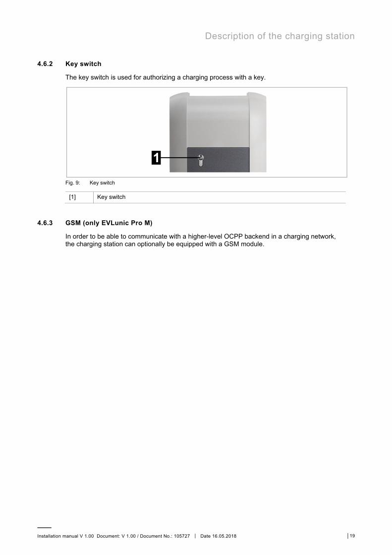
4.6.2 Key switch
The key switch is used for authorizing a charging process with a key.
Fig. 9: Key switch
[1] Key switch
4.6.3 GSM (only EVLunic Pro M)
In order to be able to communicate with a higher-level OCPP backend in a charging network, the charging station can optionally be equipped with a GSM module.

Displays and operating elements
Installation manual V 1.00 Document: V 1.00 / Document No.: 105727 │ Date 16.05.2018 │20
5 Displays and operating elements
5.1 LED bar
Fig. 10: Segments of the LED bar
The LED bar provides visual information about the current operating status of the charging station. It consists of 4 segments ([S1] to [S4]), which can light up or flash, together or individually, in various colors.
The LED bar is only visible with activated power supply.
5.2 Display (optional)
Devices with energy meters (EVLunic Pro S and Pro M) have a (dot matrix LED) display.
Fig. 11: Display
The display may show different information depending on the operating status (e.g., software version, IP address, authorization request). The main task, however, is to display the status of the internal energy meter. During periods of inactivity, the display brightness is reduced and switched off after a few minutes.
The display lights up through the housing and is only visible when the power supply is active.

Mounting and installation instructions
Installation manual V 1.00 Document: V 1.00 / Document No.: 105727 │ Date 16.05.2018 │21
6 Mounting and installation instructions
The included installation material (except EVLunic B) is suitable for cement, brick and wood (without anchors). For other surfaces, a suitable method of installation must be selected.
Depending on the device model or for special materials, the installation materials must be provided by the customer. Proper installation is absolutely necessary and lies outside of the scope of responsibility of the manufacturer.
Warning – Risk of electric shock and fire hazard! For installation on hollow walls, at least 2 mounting screws must be secured to a support element of the wall. Special hollow-wall anchors must be used for the other mounting screws. It is particularly important to ensure sufficient load-bearing capacity of the sub-construction.
Attention! – Property damage due to dampness and moisture! ■ The installation and commissioning of the charging station must take place in
a suitable environment. The charging station must be protected against rain, snow and dirt during the process. For installation outdoors, the connector panel cover is not permitted to be opened in rain, wind or snow weather conditions.
■ Only a vertical installation of the charging station is permitted. The charging station must be mounted with the supplied washers at a 90° angle to the mounting surface - no inclination is allowed, otherwise water drainage will not be possible and damage to the device will result (see illustration below).
■ Do not subject the charging station to high humidity for a longer period of time.
■ If a cold charging station is brought into a significantly warmer environment (e.g. after a longer transport in a cold environment), condensation moisture may form in the device.
■ Before connecting the charging station to the power supply, you must wait until the temperature of the charging station is the same as the room temperature and the moisture has evaporated again.
■ Always equip the charging station completely and properly with the supplied cable glands. Unused cable insertion openings must be screwed closed with blind plugs to ensure the necessary leak tightness.

Mounting and installation instructions
Installation manual V 1.00 Document: V 1.00 / Document No.: 105727 │ Date 16.05.2018 │22
Fig. 12: Water drainage
Attention! – Risk of breaking the plastic housing! ■ Countersunk screws may not be used for the mounting. ■ 4 of the supplied washers must be used under the nuts. ■ Do not tighten the mounting screws with force. ■ The mounting surface must be completely flat. Warpage of the housing must
be prevented. ■ If adjustment is necessary, the remaining 4 washers supplied must be used.

Mounting and installation instructions
Installation manual V 1.00 Document: V 1.00 / Document No.: 105727 │ Date 16.05.2018 │23
6.1 General criteria for the site selection
The charging station was constructed for the indoor and outdoor area. Accordingly, it is necessary to ensure the correct set-up requirements and the protection of the device at the installation site.
The following criteria must be taken into account when selecting a location: ■ Take into account the local electrical installation regulations, fire prevention measures and
accident prevention regulations as well as emergency routes at this site. ■ The charging station may not be installed in potentially explosive atmospheres (EX
environment). ■ The charging station may only be installed in stationary applications. ■ Mount the charging station so that it is not located in the direct flow of passersby and so that
no one can trip over connected charging cables and so that the charging cables do not cover or cross passing pedestrian and motorized traffic.
■ Do not install the charging station at locations where it is exposed to ammonia or ammonia gas (e.g. in or at stables).
■ The mounting surface must be sufficiently stable in order to withstand the mechanical forces.
■ Do not install the charging station at locations where falling objects could damage the device (e.g. hung up ladders or automobile tires).
■ The device must not be exposed to direct spray water (e.g. neighboring manual car wash facility, high-pressure cleaner, garden hose).
■ The device should be protected against direct rain as far as possible to prevent icing, hail damage or similar.
■ If possible, the device should be mounted protected from direct sunlight. Otherwise, (e.g. set up outside at a parking space) the charging current specification will be reduced to 16 A if the maximum permitted temperature is exceeded. The charging procedure can also subsequently be switched off.
■ Observe the permissible environmental conditions (see 12 Technical data).
Observe the internationally valid installation standards (e.g. IEC 60364-1 and IEC 60364-5-52) and comply with the nationally applicable installation standards and regulations.
Mounting and installation instructions
Installation manual V 1.00 Document: V 1.00 / Document No.: 105727 │ Date 16.05.2018 │24
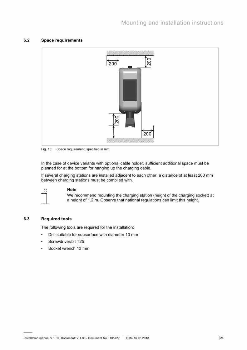
6.2 Space requirements
Fig. 13: Space requirement, specified in mm
In the case of device variants with optional cable holder, sufficient additional space must be planned for at the bottom for hanging up the charging cable.
If several charging stations are installed adjacent to each other, a distance of at least 200 mm between charging stations must be complied with.
Note We recommend mounting the charging station (height of the charging socket) at a height of 1.2 m. Observe that national regulations can limit this height.
6.3 Required tools
The following tools are required for the installation: ■ Drill suitable for subsurface with diameter 10 mm ■ Screwdriver/bit T25 ■ Socket wrench 13 mm

Mounting and installation instructions
Installation manual V 1.00 Document: V 1.00 / Document No.: 105727 │ Date 16.05.2018 │25
6.4 Mounting the charging station
The charging station must be prepared for this before mounting. To do this, proceed as follows:
1. Unscrew the two screws on the bottom side of the housing cover.
2. Lift the housing cover at bottom max. 1 cm [1] and then push upwards [2].
3. Loosen the four screws of the connection panel cover and remove the connection pane cover upwards.

Mounting and installation instructions
Installation manual V 1.00 Document: V 1.00 / Document No.: 105727 │ Date 16.05.2018 │26
4. Loosen the two screws of the terminal cover and remove the terminal cover upwards.
5. Place the charging station on a stable surface. 6. Using a hammer and flat-head screwdriver, gently knock out the required cable insertion
openings – Surface-mounting cable insertion: Cable insertion openings on the top side – Flush-mounting cable insertion: Cable insertion openings on the back side
7. Insert the cable glands (surface-mounted cable insertion) or double-membrane seals (flush-mounted cable insertion) into the corresponding cable insertion openings.
The charging station is now ready for installation.

Mounting and installation instructions
Installation manual V 1.00 Document: V 1.00 / Document No.: 105727 │ Date 16.05.2018 │27
To mount the charging station, proceed as follows:
1. Mark the 4 holes 1 in the designated location on the wall. The supplied drilling template can be used for this purpose.
Fig. 14: Drilling template
[1] Mounting holes [2] Cable insertion openings
[3] Cable holder holes
2. If there is a cable holder, mark the cable holder holes [3]. 3. Drill boreholes and, if necessary, insert anchors in the holes.
Fig. 15: Inserting anchor
[1] Washer for adjusting [2] Rear wall of the charging station
[3] Washer for nut [4] Nut
[5] Hanger bolt [6] 20 mm

Mounting and installation instructions
Installation manual V 1.00 Document: V 1.00 / Document No.: 105727 │ Date 16.05.2018 │28
4. Turn the hanger bolts into the hole / anchors until the thread still protrudes approx. 20 mm [x].
5. Pull the cable through the prepared openings on the charging station. Pay attention to leak tightness!
6. 4 of the supplied washers can be used to compensate for any unevenness and to ensure proper water flow behind the device: If necessary, place the washers [1] on the hanger bolts.
7. Position the charging station on the wall and secure it with the 4 washers [3] and nuts [4] to the hanger bolts [5].
The charging station is now mounted on the wall and ready for cabling.
Connections and wiring
Installation manual V 1.00 Document: V 1.00 / Document No.: 105727 │ Date 16.05.2018 │29
7 Connections and wiring
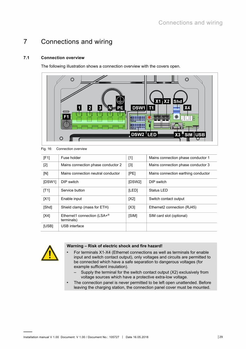
7.1 Connection overview
The following illustration shows a connection overview with the covers open.
Fig. 16: Connection overview
[F1] Fuse holder [1] Mains connection phase conductor 1
[2] Mains connection phase conductor 2 [3] Mains connection phase conductor 3
[N] Mains connection neutral conductor [PE] Mains connection earthing conductor
[DSW1] DIP switch [DSW2] DIP switch
[T1] Service button [LED] Status LED
[X1] Enable input [X2] Switch contact output
[Shd] Shield clamp (mass for ETH) [X3] Ethernet2 connection (RJ45)
[X4] Ethernet1 connection (LSA+® terminals)
[SIM] SIM card slot (optional)
[USB] USB interface
Warning – Risk of electric shock and fire hazard! ■ For terminals X1-X4 (Ethernet connections as well as terminals for enable
input and switch contact output), only voltages and circuits are permitted to be connected which have a safe separation to dangerous voltages (for example sufficient insulation). – Supply the terminal for the switch contact output (X2) exclusively from
voltage sources which have a protective extra-low voltage. ■ The connection panel is never permitted to be left open unattended. Before
leaving the charging station, the connection panel cover must be mounted.
Connections and wiring
Installation manual V 1.00 Document: V 1.00 / Document No.: 105727 │ Date 16.05.2018 │30
7.2 Required tools
The following tools are required for the electrical installation: ■ Flathead screwdriver for supply terminals (blade width 5.5 mm) ■ Flathead screwdriver for terminals X1/X2 (blade width 3.0 mm) ■ Phillips head screwdriver PH2 ■ Mounting tools for cable screw connections M16 (width across flats 20 mm) and M32 (width
across flats 36 mm) ■ LSA+® insertion tool (optional)
7.3 Power supply
The power supply (supply line) must be hardwired to an existing domestic installation and comply with the applicable national regulations.
Mains disconnector The charging station does not have its own power switch. The line circuit breaker of the supply line serves as a mains disconnector.
Selection of RCD / fault-current circuit breaker Each charging station must be connected via a separate RCD (Residual Current Device / fault-current circuit breaker). No other consumers may be connected to this circuit.
An RCD with at least Type A must be used since all EVLunic variants have an internal DC fault current monitoring ≥ 6 mA.
During installation, other important issues such as "cascading” of RCD and selection of a suitable line circuit breaker must be considered.
Dimensioning of the line circuit breaker When dimensioning the line circuit breaker, the increased ambient temperatures in the control cabinet must also be taken into account! Under certain circumstances, this can make a reduction of the charging current specification necessary in order to increase the system availability.
The nominal current must be determined in accordance with the type plate data in coordination with the desired charging power (DIP switch settings for charging current specification) and the supply line.
I(DIP switch) ≤ I(circuit breaker) ≤ I(supply line) ≤ I(nominal current)
Dimensioning of the power supply line When dimensioning the power supply line also observe the possible reduction factors and the increased environmental temperatures inside the connection area of the charging station (see temperature rating of the supply terminals)! Under certain circumstances, this can lead to an increase of the cable cross-section and to the adaptation of the temperature resistance of the power supply line.
Connections and wiring
Installation manual V 1.00 Document: V 1.00 / Document No.: 105727 │ Date 16.05.2018 │31
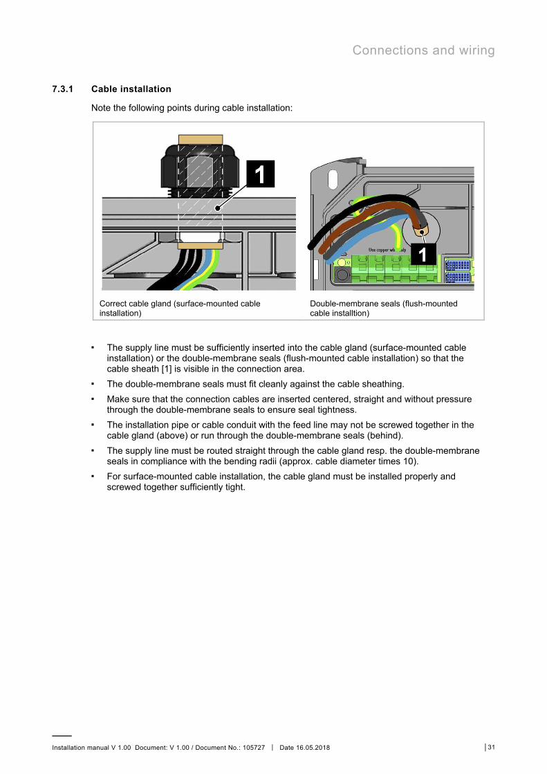
7.3.1 Cable installation
Note the following points during cable installation:
Correct cable gland (surface-mounted cable installation)
Double-membrane seals (flush-mounted cable installtion)
■ The supply line must be sufficiently inserted into the cable gland (surface-mounted cable
installation) or the double-membrane seals (flush-mounted cable installation) so that the cable sheath [1] is visible in the connection area.
■ The double-membrane seals must fit cleanly against the cable sheathing. ■ Make sure that the connection cables are inserted centered, straight and without pressure
through the double-membrane seals to ensure seal tightness. ■ The installation pipe or cable conduit with the feed line may not be screwed together in the
cable gland (above) or run through the double-membrane seals (behind). ■ The supply line must be routed straight through the cable gland resp. the double-membrane
seals in compliance with the bending radii (approx. cable diameter times 10). ■ For surface-mounted cable installation, the cable gland must be installed properly and
screwed together sufficiently tight.
Connections and wiring
Installation manual V 1.00 Document: V 1.00 / Document No.: 105727 │ Date 16.05.2018 │32
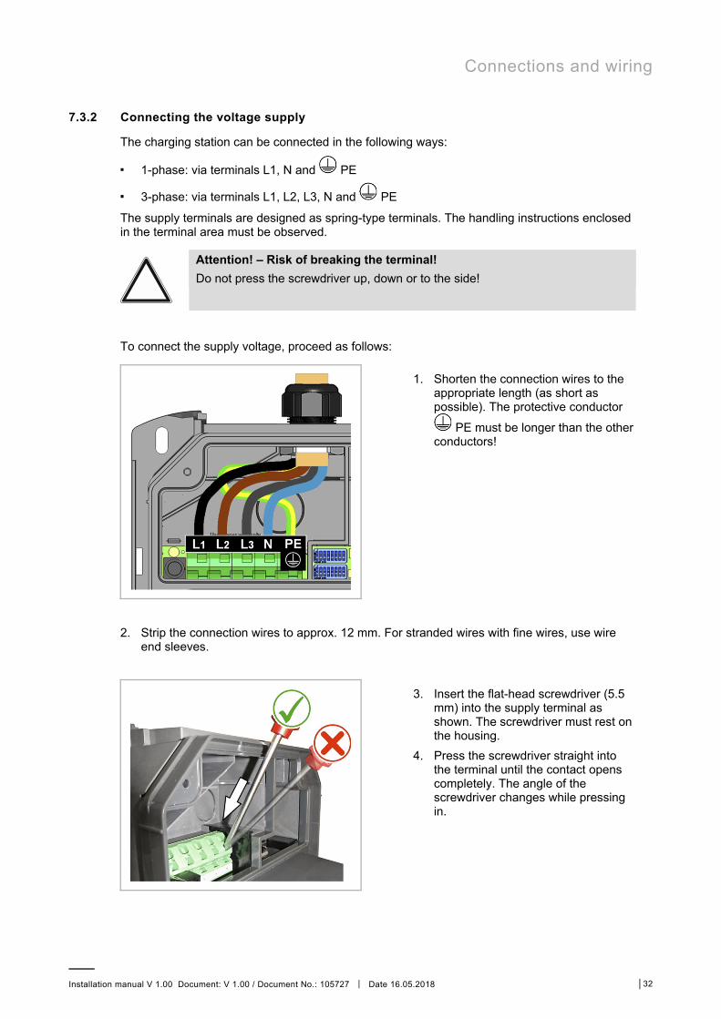
7.3.2 Connecting the voltage supply
The charging station can be connected in the following ways:
■ 1-phase: via terminals L1, N and PE
■ 3-phase: via terminals L1, L2, L3, N and PE
The supply terminals are designed as spring-type terminals. The handling instructions enclosed in the terminal area must be observed.
Attention! – Risk of breaking the terminal! Do not press the screwdriver up, down or to the side!
To connect the supply voltage, proceed as follows:
1. Shorten the connection wires to the appropriate length (as short as possible). The protective conductor
PE must be longer than the other conductors!
2. Strip the connection wires to approx. 12 mm. For stranded wires with fine wires, use wire
end sleeves.
3. Insert the flat-head screwdriver (5.5 mm) into the supply terminal as shown. The screwdriver must rest on the housing.
4. Press the screwdriver straight into the terminal until the contact opens completely. The angle of the screwdriver changes while pressing in.

Connections and wiring
Installation manual V 1.00 Document: V 1.00 / Document No.: 105727 │ Date 16.05.2018 │33
5. Insert connection wire into the designated terminal opening.
6. Pull out the screwdriver straight.
7. Repeat these steps for the other connection wires.
The charging station is connected to the power supply.
The charging station is set to 10 A in the delivery state. In order to adapt the maximum current to the installed line circuit breaker, a configuration via the DIP switches is necessary. For details, see 8.1 DIP switch settings.

Connections and wiring
Installation manual V 1.00 Document: V 1.00 / Document No.: 105727 │ Date 16.05.2018 │34
7.3.3 Electrical connection to special systems of AC power supply
Note The charging station can in principle be connected to TN, TT and IT systems of AC power supply networks. Pay attention to the restrictions of your vehicle manufacturer.
We recommend connecting the charging station in delta networks without upstream transformer only with single phase. A three-phase connection in delta networks should only take place with an upstream transformer ("triangle-to-star converter").
Fig. 17: Connection to a three-wire IT system with 230 V

Connections and wiring
Installation manual V 1.00 Document: V 1.00 / Document No.: 105727 │ Date 16.05.2018 │35
7.4 Enable input X1 (except EVLunic B)
The enable input X1 is equipped for use with a potential-free contact. Using the enable input, it is possible to control the charging station using external components (e.g. external key switches, house control, photovoltaic system, ripple control receivers, ...). The terminal is designed as a spring-type terminal.
Enable contact State of the charging station
Open Locked
Closed Ready for operation
The use of the enable input must be activated with a DIP switch setting (DSW1.1 to ON). ■ DSW1.1 ON means a charge enable with X1 closed AND correct RFID authorization. ■ DSW1.1 OFF means charge enable with X1 closed OR correct RFID authorization.
For further information see 8.1 DIP switch settings.
7.4.1 Connection diagram
Fig. 18: Connection diagram X1
7.5 Switch contact output X2 (except EVLunic B)
The switch contact output X2 (signal contact) is a potential-free relay contact and can be used as a charging status display (default use) or contactor monitoring. The terminal is designed as a spring-type terminal.
The use of the switch contact output must be activated with a DIP switch setting (DSW1.2 to ON). ■ DSW1.2 ON means X2 is used as contactor monitoring. ■ DSW1.2 OFF means X2 is used as the charge status indicator. For further information see 8.1 DIP switch settings.

Connections and wiring
Installation manual V 1.00 Document: V 1.00 / Document No.: 105727 │ Date 16.05.2018 │36
Charging status display
Enable contact State of the charging station
Open Vehicle is connected, charging station not in operation or error.
Closed Charging station is ready for operation and no vehicle is connected.
Contactor monitoring
Enable contact State of the charging station
Open No error.
Closed A switch contact of the contactor is stuck.
7.5.1 Connection diagram
Fig. 19: Connection diagram X2
■ Safety extra-low voltage Vcc < 50 VAC ■ F ≤ 0.5A current-limiting protective equipment

Connections and wiring
Installation manual V 1.00 Document: V 1.00 / Document No.: 105727 │ Date 16.05.2018 │37
7.5.2 Connection example
The switch contact output can be used to switch off the charging station (disconnect the current) by means of an overriding disconnect solution.
[-Q1] Main switch [-Q2] Line circuit breaker + FI switch
[-Q3] Contactor / Relay [-F1] Current-limiting equipment
[-U1] Undervoltage trigger [-X2] Switch contact output
7.6 Ethernet connection X3 and X4 (optional)
Warning – Danger from compensation currents on shielding! ■ Compensation currents flowing through shielding in extended systems can
lead to damage to the interfaces and hazards when working on the data lines.
■ Any measures (such as connecting to a shared distribution board, expanding a TN-S network, etc.) should be discussed with the person responsible for building services.
Note The Ethernet1 connector X4 (LSA+®) and the Ethernet2 connector X3 (RJ45) are connected in parallel on the PCB and can not be used at the same time. The unused connection must be disconnected if necessary (e.g. during servicing).
The Ethernet1 connection X4 is designed as terminal block in LSA+® technology. A hard-wired communication (e.g. for SmartHome or a charging network) may only be carried out on this LSA+® connection.
The Ethernet2 connector X3 (RJ45) is for device diagnosis purposes only (debugging).

Connections and wiring
Installation manual V 1.00 Document: V 1.00 / Document No.: 105727 │ Date 16.05.2018 │38
Color coding According to the cabling standards used in the building, the contacts are wired according to TIA-568A/B for 100BaseT as follows:
Pin -568A Pair -568B Pair -568A Color -568B Color
1 (Tx+) 3 2 white / green stripe
white / orange stripe
2 (Tx−) 3 2
green / white stripe or green
or orange
orange / white stripe
3 (Rx+) 2 3 white / orange stripe
white / green stripe
4 (Rx−) 2 3
orange / white stripe or orange
or green
green / white stripe
Terminal data
Category Wire diameter Insulation diameter
Inflexible cable Cat 5e / Cat6 STP
0.36 mm (AWG 27) 0.7 – 0.75 mm
0.4 – 0.64 mm (AWG 26 – AWG 22)
0.7 – 1.4 mm
Cat 6 STP 0.51 – 0.81 mm (AWG 24 – AWG 20)
1.0 – 1,4 mm
Flexible cable Cat 5e / Cat 6 STP
7x 0.2 mm (AWG 24)
1.1 – 1.4 mm
Preparing the connection cable To prepare the connection cable, proceed as follows:
1. Strip the connection cable about 6 cm.
2. Knock back approx. 1 cm of shielding all over and wrap with conductive textile adhesive tape.

Connections and wiring
Installation manual V 1.00 Document: V 1.00 / Document No.: 105727 │ Date 16.05.2018 │39
Connecting the cable To connect the cable, proceed as follows:
1. Fix the connecting cable at the point of the wrapped-around shielding braid in the shield clamp [K].
2. Tighten the shield clamp [Shd]. 3. Clamp the wires to the terminal block
[ETH] using an insertion tool.
Configuration
Installation manual V 1.00 Document: V 1.00 / Document No.: 105727 │ Date 16.05.2018 │40
8 Configuration
The basic configuration of the charging station is done using the DIP switches.
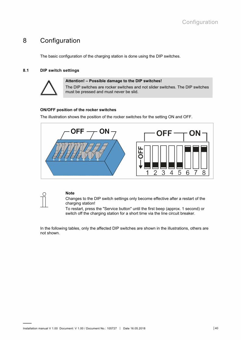
8.1 DIP switch settings
Attention! – Possible damage to the DIP switches! The DIP switches are rocker switches and not slider switches. The DIP switches must be pressed and must never be slid.
ON/OFF position of the rocker switches The illustration shows the position of the rocker switches for the setting ON and OFF.
Note Changes to the DIP switch settings only become effective after a restart of the charging station! To restart, press the "Service button" until the first beep (approx. 1 second) or switch off the charging station for a short time via the line circuit breaker.
In the following tables, only the affected DIP switches are shown in the illustrations, others are not shown.
Configuration
Installation manual V 1.00 Document: V 1.00 / Document No.: 105727 │ Date 16.05.2018 │41
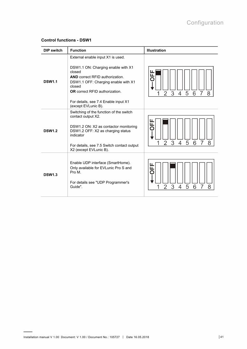
Control functions - DSW1
DIP switch Function Illustration
DSW1.1
External enable input X1 is used. DSW1.1 ON: Charging enable with X1 closed AND correct RFID authorization. DSW1.1 OFF: Charging enable with X1 closed OR correct RFID authorization. For details, see 7.4 Enable input X1 (except EVLunic B).
DSW1.2
Switching of the function of the switch contact output X2. DSW1.2 ON: X2 as contactor monitoring DSW1.2 OFF: X2 as charging status indicator For details, see 7.5 Switch contact output X2 (except EVLunic B).
DSW1.3
Enable UDP interface (SmartHome). Only available for EVLunic Pro S and Pro M. For details see "UDP Programmer's Guide".

Configuration
Installation manual V 1.00 Document: V 1.00 / Document No.: 105727 │ Date 16.05.2018 │42
Adjust current - DSW1.6 to DSW1.8
Note Only a maximum value, which is smaller or equal to the operating current according to the type plate, can be set with the DIP switches.
DIP switch Current Illustration
DSW1.6 DSW1.7 DSW1.8
10 A
DSW1.6 DSW1.7 DSW1.8
13 A
DSW1.6 DSW1.7 DSW1.8
16 A
DSW1.6 DSW1.7 DSW1.8
20 A
DSW1.6 DSW1.7 DSW1.8
25 A
DSW1.6 DSW1.7 DSW1.8
32 A

Configuration
Installation manual V 1.00 Document: V 1.00 / Document No.: 105727 │ Date 16.05.2018 │43
Get IP address via DHCP server - DSW2.1 to DSW2.4
DIP switch Function Illustration
DSW2.1 DSW2.2 DSW2.3 DSW2.4
By default, the charging process is carried out independently by the charging station without a higher-level control system. The charging station attempts to obtain an IP address via DHCP server, if needed. This also corresponds to the basic settings for charging stations without network connection. Not valid for EVLunic Pro M.
Set fixed IP address - DSW2.1 to DSW2.4
DIP switch Function Illustration
DSW2.1 DSW2.2 DSW2.3 DSW2.4
If there are several charging stations in a network, an addressing of the charging stations is necessary. The last two digits of the IP address (192.168.25.xx) can be specified with the DIP switches DSW2.1 to DSW2.4. Each DIP switch has a specific value when it is set to "ON". A DIP switch set to "OFF" has the value 0.
DSW2.1 = ON = value: 1 DSW2.2 = ON = value: 2 DSW2.3 = ON = value: 4 DSW2.4 = ON = value: 8
The address is obtained by adding the values of the DIP switches and increasing the result by 10:
Sum of the DIP switch values + 10 Thus, the addresses 11 to 25 are settable.
Not valid for EVLunic Pro M.
Example of IP address xxx.xxx.xx.21
DSW2.1 = ON = 1 DSW2.2 = ON = 2 DSW2.3 = OFF = 0 DSW2.4 = ON = 8
Address = 1 + 2 + 0 + 8 + 10 = 21
Activation communication - DSW2.5
DIP switch Function Illustration
DSW2.5
Activation of communication in the charging network. This DIP switch setting must be made for each master and slave charging station to enable charging station communication.
Configuration
Installation manual V 1.00 Document: V 1.00 / Document No.: 105727 │ Date 16.05.2018 │44
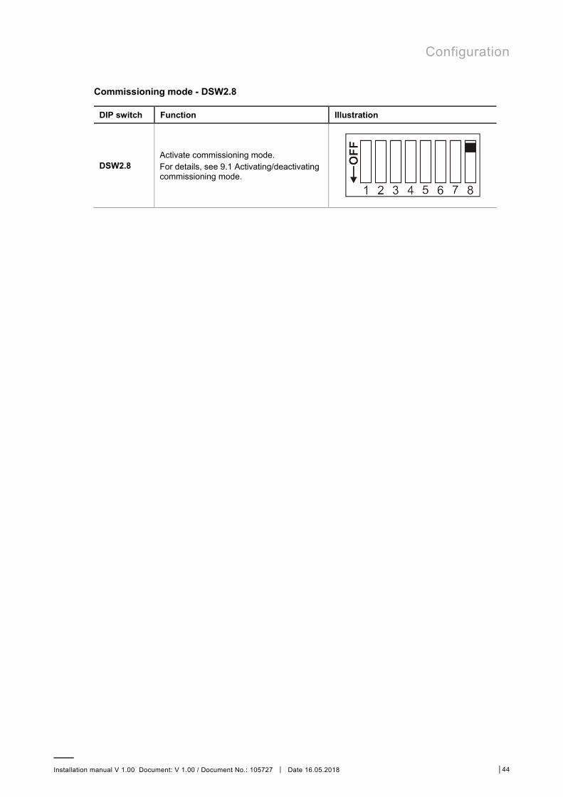
Commissioning mode - DSW2.8
DIP switch Function Illustration
DSW2.8 Activate commissioning mode. For details, see 9.1 Activating/deactivating commissioning mode.

Configuration
Installation manual V 1.00 Document: V 1.00 / Document No.: 105727 │ Date 16.05.2018 │45
8.2 Prepare GSM connection (optional)
Certain device variants have a GSM module. To use the GSM function, a SIM card must be inserted in the GSM module.
Fig. 20: Insertion slot
8.2.1 Inserting the SIM card
Attention! – Property damage due to contamination! Pay attention to cleanliness in the connection panel, so that no contamination (wire scraps, ...) passes through the SIM insertion slot into the inside of the charging station.
Fig. 21: Inserting the SIM card
1. If still present, remove the indicated sticker above the SIM insertion slot. 2. Lightly press the SIM card into the slot until the spring mechanism locks.

Configuration
Installation manual V 1.00 Document: V 1.00 / Document No.: 105727 │ Date 16.05.2018 │46
8.2.2 Removing the SIM card
Fig. 22: Removing the SIM card
1. By lightly pressing the SIM card with your finger, the spring mechanism is activated and the SIM card is ejected.
2. Remove the SIM card.

Commissioning
Installation manual V 1.00 Document: V 1.00 / Document No.: 105727 │ Date 16.05.2018 │47
9 Commissioning
The inspections and tests to be performed on the electrical connections and the correct functioning up to the acceptance of the charging station (in accordance with the locally applicable directives and laws) may only be carried out by a qualified electrician.
The following work must be carried out at the start of commissioning: ■ Remove all residual installation and connection materials from the connection area. ■ Check all screw and clamp connections for tightness. ■ Check that all unused cable screw connections are properly sealed with blind plugs or
dummy screw fittings. ■ Switch on the voltage of the supply line. After 15 - 20 seconds, the LED bar should flash
slowly blue or green. This indicates that the self-test, which is performed automatically at each startup, was successful.
The following steps are necessary during the initial commissioning: ■ Activate commissioning mode ■ Perform safety checks ■ Deactivate commissioning mode ■ Mount covers ■ Attach seal

Commissioning
Installation manual V 1.00 Document: V 1.00 / Document No.: 105727 │ Date 16.05.2018 │48
9.1 Activating/deactivating commissioning mode
The charging station can be put into a special commissioning mode to help facilitate the system inspection. The device carries out an extended self-test (interlocking, contactor control, current measurement, ...). Furthermore, the contactor is switched on with a time limit, to facilitate initial testing in this mode, even without a vehicle being plugged in. The charging socket is locked to prevent a cable from being plugged in.
A normal charging procedure is not possible in commissioning mode.
Note For safety reasons, the commissioning mode is indicated on the charging station by an orange display on segment S3 of the LED bar (-/-/orange/-).
Activate commissioning mode To activate the charging station commissioning mode, proceed as follows:
1. Set DIP switch DSW2.8 to ON (see 8.1 DIP switch settings). 2. Restart the charging station by pressing the "Service button" until the first beep (approx.
1 second).
Commissioning mode is activated as soon as the LED bar lights up orange. You now have approx. 10 minutes to perform the required inspections and acceptance tests. The contactor is then deactivated and the charging station goes into an error state. This is indicated by the LED bar (white / red / red / red). By restarting via the "Service button", the commissioning mode can be reactivated.
Note The energy in commissioning mode is taken into account when displaying the total energy. During the commissioning mode, the display is displayed in "watt-hours" (Wh).
Deactivate commissioning mode In order to be able to operate the charging station properly, the commissioning mode must be deactivated again. To do this, proceed as follows:
1. Set DIP switch DSW2.8 to OFF (see 8.1 DIP switch settings). 2. Restart the charging station by pressing the "Service button" until the first beep (approx.
1 second).
The charging station starts up again in normal mode and is ready for operation.

Commissioning
Installation manual V 1.00 Document: V 1.00 / Document No.: 105727 │ Date 16.05.2018 │49
9.2 Perform safety checks
Before the initial use, check the effectiveness of the safety measure(s) of the system according to the nationally applicable regulations.
Electrical systems or devices must be checked by the installer of the system or device before the initial operation. This also applies for the expansion or modification of existing systems or electrical devices. It is essential that all conditions for the safety measures are observed.
Moreover, the following points are to be taken into account: ■ The checks (continuity of the connections of the protective conductor, insulation resistance,
RCD (FI) triggering current, triggering time,…) are to be performed. ■ The measurement devices must comply with the national regulations! ■ The measurement results are to be documented. A test report is to be created and saved
before the check.
9.3 Mount covers
In order to operate the charging station correctly, all covers must be inserted and screwed tight. If necessary, a seal can be attached.
To mount all covers, proceed as follows:
1. Insert terminal cover and tighten with 2 screws. – If necessary, the right upper
screw can be provided with the supplied sealing cap (see 9.4 Attach seal).
2. Insert connection panel cover and tighten with 4 screws with 2 Nm. The tabs on the connection panel cover must be flush with the enclosing housing. Only then will the device be properly sealed. – If necessary, the right upper
screw can be provided with the supplied sealing cap (see 9.4 Attach seal).

Commissioning
Installation manual V 1.00 Document: V 1.00 / Document No.: 105727 │ Date 16.05.2018 │50
3. Hook in the housing cover at the top [1] and close it at the bottom [2]. The housing cover must glide into the guides without considerable resistance. The housing cover must be correctly seated in the housing guide on all sides.
4. Secure the housing cover with 2 screws at the bottom.
All covers are mounted and the charging station is ready for use.

Commissioning
Installation manual V 1.00 Document: V 1.00 / Document No.: 105727 │ Date 16.05.2018 │51
9.4 Attach seal
Included with the charging station (except EVLunic B) are devices for sealing the terminal cover and the connection panel cover. If required, these can be used to prevent or identify tampering attempts by unauthorized persons at charging stations with preconfiguration or special suitability (MID calibration validity).
To attach the seals, proceed as follows:
1. If necessary, open the covers of the charging station until the cover to be sealed is accessible.
2. Loosen the right upper screw of the cover to be sealed.
3. Insert the screw into the sealing cap. 4. Screw the screw with the sealing cap
back into the cover.
5. Close the cover of the sealing cap. 6. Thread the sealing wire through the
opening of the sealing cap over the screw and place the seal.
The seal is attached. If necessary, reinstall all other covers of the charging station.

Maintenance
Installation manual V 1.00 Document: V 1.00 / Document No.: 105727 │ Date 16.05.2018 │52
10 Maintenance
10.1 Replacing the fuse
Fuse Current / Voltage Type Dimensions
F1 6.3 A / 250 V Delay with high breaking capacity (>1500A) (T) (H) 5 x 20 mm fuse
To replace the fuse, proceed as follows:
1. Switch off the supply voltage of the charging station. 2. Remove the housing cover, the connection panel cover, and the terminal cover.
– If there is a seal on the connection panel cover or terminal cover, it may only be removed by an authorized person! After changing the fuse, the seal must be replaced.
3. Using a screwdriver, press into the opening of the fuse holder.
4. Screw the fuse holder counterclockwise until it springs forward automatically by the spring.
5. Replace the fuse. 6. Press the fuse holder in and tighten clockwise. 7. Mount the housing covers on the charging station again.
The fuse has now been replaced.
10.2 Troubleshooting
Further information (e.g. operating and configuration instructions) and contact details are available on the ABB website:
new.abb.com/ev-charging

Maintenance
Installation manual V 1.00 Document: V 1.00 / Document No.: 105727 │ Date 16.05.2018 │53
10.3 Software update
It is recommended to always keep the charging station up-to-date, as it contains functional enhancements and bug fixes. A software update is available on the ABB website:
new.abb.com/ev-charging
The information and instructions for the current software update from the associated release notes must also be observed.
To perform the software update via USB or the network connection to EVLunic B, B+ and Pro S, the instructions are included in the *.zip file. For EVLunic Pro M, the configuration manual must also be observed.
Note A software update process on the charging station is indicated by a slow orange flashing of the LED bar.
10.4 Replace the SIM Card
To replace the SIM card, proceed as follows:
1. Remove the existing SIM card from the GSM module (see 8.2.2 Removing the SIM card). 2. Insert the new SIM card into the GSM module (see 8.2.1 Inserting the SIM card).

Disposal
Installation manual V 1.00 Document: V 1.00 / Document No.: 105727 │ Date 16.05.2018 │54
11 Disposal
11.1 Disposal of the charging station
Caution Please observe the regulations regarding disposal of electric appliances and electronic devices!
■ The symbol with the crossed-out waste container means that electrical and electronic devices including their accessories must not be disposed of in the household garbage.
■ The materials are recyclable in accordance with their labeling. You can make an important contribution to protecting our environment by reusing, renewing and recycling materials and old appliances.

Technical data
Installation manual V 1.00 Document: V 1.00 / Document No.: 105727 │ Date 16.05.2018 │55
12 Technical data
12.1 General
Overvoltage category: III according to EN 60664
Protection class: I
Protection type: IP54 Protection against mechanical impact: IK08 (except for cylinder lock) Rated short-time withstand: < 10 kA effective value according to EN
61439-1
Internal residual direct current detection
Residual Direct Current Detecting Device: ≥ 6 mA
12.2 Power supply
Power consumption
Rated supply voltage (Europe) ■ B: ■ B+ / Pro S / Pro M:
■ 230 V ■ 3 x 230 V / 400 V
Power consumption ■ B: ■ Idle: 2 W
■ Plugged: 3 W ■ Charging: 5.5 W
■ B+ / Pro S: ■ Idle: 3 W ■ Plugged: 4.5 W ■ Charging: 6.5 W
■ Pro M: ■ Idle: 4 W ■ Plugged: 5 W ■ Charging: 7 W
Rated current (configurable): 10 A / 13 A / 16 A / 20 A / 25 A / 32 A 1-phase or 3-phase
Line frequency: 50 Hz
Mains forms: TT / TN / IT
Technical data
Installation manual V 1.00 Document: V 1.00 / Document No.: 105727 │ Date 16.05.2018 │56
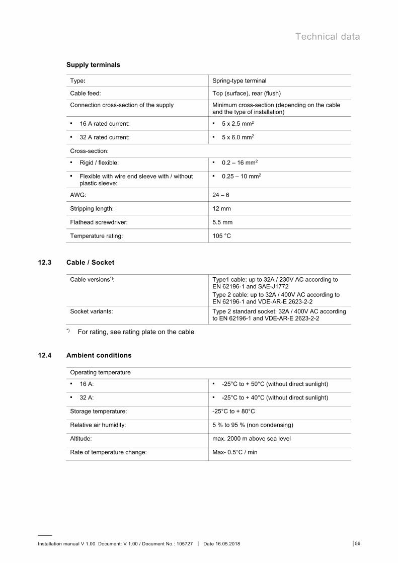
Supply terminals
Type: Spring-type terminal
Cable feed: Top (surface), rear (flush)
Connection cross-section of the supply Minimum cross-section (depending on the cable and the type of installation)
■ 16 A rated current: ■ 5 x 2.5 mm2
■ 32 A rated current: ■ 5 x 6.0 mm2
Cross-section: ■ Rigid / flexible: ■ 0.2 – 16 mm2
■ Flexible with wire end sleeve with / without plastic sleeve:
■ 0.25 – 10 mm2
AWG: 24 – 6
Stripping length: 12 mm
Flathead screwdriver: 5.5 mm
Temperature rating: 105 °C
12.3 Cable / Socket
Cable versions*):
Type1 cable: up to 32A / 230V AC according to EN 62196-1 and SAE-J1772 Type 2 cable: up to 32A / 400V AC according to EN 62196-1 and VDE-AR-E 2623-2-2
Socket variants:
Type 2 standard socket: 32A / 400V AC according to EN 62196-1 and VDE-AR-E 2623-2-2
*) For rating, see rating plate on the cable
12.4 Ambient conditions
Operating temperature ■ 16 A: ■ -25°C to + 50°C (without direct sunlight)
■ 32 A: ■ -25°C to + 40°C (without direct sunlight)
Storage temperature: -25°C to + 80°C
Relative air humidity: 5 % to 95 % (non condensing)
Altitude: max. 2000 m above sea level
Rate of temperature change: Max- 0.5°C / min
Technical data
Installation manual V 1.00 Document: V 1.00 / Document No.: 105727 │ Date 16.05.2018 │57
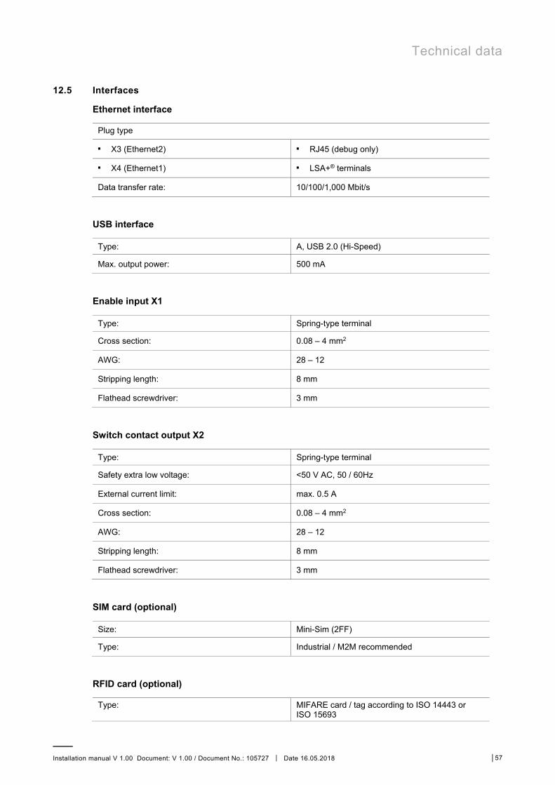
12.5 Interfaces
Ethernet interface
Plug type
■ X3 (Ethernet2) ■ RJ45 (debug only)
■ X4 (Ethernet1) ■ LSA+® terminals
Data transfer rate: 10/100/1,000 Mbit/s
USB interface
Type: A, USB 2.0 (Hi-Speed)
Max. output power: 500 mA
Enable input X1
Type: Spring-type terminal
Cross section: 0.08 – 4 mm2
AWG: 28 – 12
Stripping length: 8 mm
Flathead screwdriver: 3 mm
Switch contact output X2
Type: Spring-type terminal
Safety extra low voltage: <50 V AC, 50 / 60Hz
External current limit: max. 0.5 A
Cross section: 0.08 – 4 mm2
AWG: 28 – 12
Stripping length: 8 mm
Flathead screwdriver: 3 mm
SIM card (optional)
Size: Mini-Sim (2FF)
Type: Industrial / M2M recommended
RFID card (optional)
Type: MIFARE card / tag according to ISO 14443 or ISO 15693

Technical data
Installation manual V 1.00 Document: V 1.00 / Document No.: 105727 │ Date 16.05.2018 │58
Key-operated switch (optional)
Type: Profile half cylinder according to EN 1303 or DIN 18252
Length: 30 mm
WLAN / Wifi interface (only EVLunic Pro M)
Type: IEEE 802.11 b, g, n 2.4 GHz
Supported modes: AP Ad-hoc-Mode, Client Mode
GSM interface (only EVLunic Pro M, optional)
Type: 3 G
Transmission rate: max. 230 kBaud/s on the data channel
Frequency bands: GSM900, DCS1800, UMTS B1, UMTS B8
12.6 MID specific data
Meter type: Electricity meter for active power
Measurement type: Converter measurement
Non-return device: Electronic
Accuracy class: Class B (according to EN 50470-1, -3)
Minimum current: 0.15 A
Reference current: 3 A
Maximum current: 16 A / 20 A / 32 A
Pulse output in test mode: 10,000 pulses/kWh
Mechanical environmental conditions: Class M1 (according to MID 2014/32/EU)
Electromagnetic environmental conditions: Class E2 (according to MID 2014/32/EU)

Technical data
Installation manual V 1.00 Document: V 1.00 / Document No.: 105727 │ Date 16.05.2018 │59
12.7 Dimensions
Height: 495 mm
Width: 240 mm
Depth: 163 mm
Weight: approx. 6 - 10 kg (depending on device version)

Technical data
Installation manual V 1.00 Document: V 1.00 / Document No.: 105727 │ Date 16.05.2018 │60
Version with standard socket (Type 2)
Fig. 23: Dimensions in millimeters

Technical data
Installation manual V 1.00 Document: V 1.00 / Document No.: 105727 │ Date 16.05.2018 │61
Version with charging cable and holder
Fig. 24: Dimensions in millimeters

EU Directives and Standards
Installation manual V 1.00 Document: V 1.00 / Document No.: 105727 │ Date 16.05.2018 │62
13 EU Directives and Standards
2014/35/EU Low-voltage Directive
2014/30/EU Electromagnetic Compatibility Directive
2014/53/EU Radio Equipment Directive (RED)
2011/65/EU Directive on the restriction of the use of certain hazardous substances (RoHS)
2012/19/EU Directive for waste electrical and electronic equipment (WEEE)
2014/32/EU European Measuring Device Directive (MID)

Declaration of conformity
Installation manual V 1.00 Document: V 1.00 / Document No.: 105727 │ Date 16.05.2018 │63
14 Declaration of conformity

Declaration of conformity
Installation manual V 1.00 Document: V 1.00 / Document No.: 105727 │ Date 16.05.2018 │64
(*1)
EVLunic – type designation
EVLunic – Pro M W 22 – § – R – M
I II III IV V VI VII VIII IX
I Product EVLunic EVLunic
II Device series
B B+ Pro S Pro M
B B+ Pro S Pro M
III Form factor W W
IV Output 4.6 11 22
4.6 kW 11 kW 22 kW
V Cable / Socket
T S p G
Socket Shutter Type 1 Type 2
VI Cable type
1111
4 6
No cable 4 m cable 5 m cable
VII Authorization
1111
R K
None RFID Key switch
VIII Communication 1111
C None Cellular (3G)
IX Metering 1111
E M
None Energy meter (not calibrated) Calibratable energy meter (MID)
(*2) http://new.abb.com
ABBEVLunic_simplified_DoC_V-1.00 Page 2 of 2
A member of the ABB Group ABB B.V. George Hintzenweg 81 3068 AX Rotterdam Netherlands Phone: +31 10 407 8911 Fax: +31 10 407 8452 [email protected]
Notice We reserve the right to at all times make technical changes as well as changes to the contents of this document without prior notice. The detailed specifications agreed upon apply for orders. ABB accepts no responsibility for possible errors or incompleteness in this document. We reserve all rights to this document and the topics and illustrations contained therein. The document and its contents, or extracts thereof, must not be reproduced, transmitted or reused by third parties without prior written consent by ABB
Inst
alla
tion
man
ual V
1.0
0 1
0572
7 │
Dat
e 16
.05.
2018
Copyright© 2018 ABB Specifications are subject to change due to further technical developments.
Details presented may be subject to correction.
All rights reserved