Embed Size (px)
Citation preview
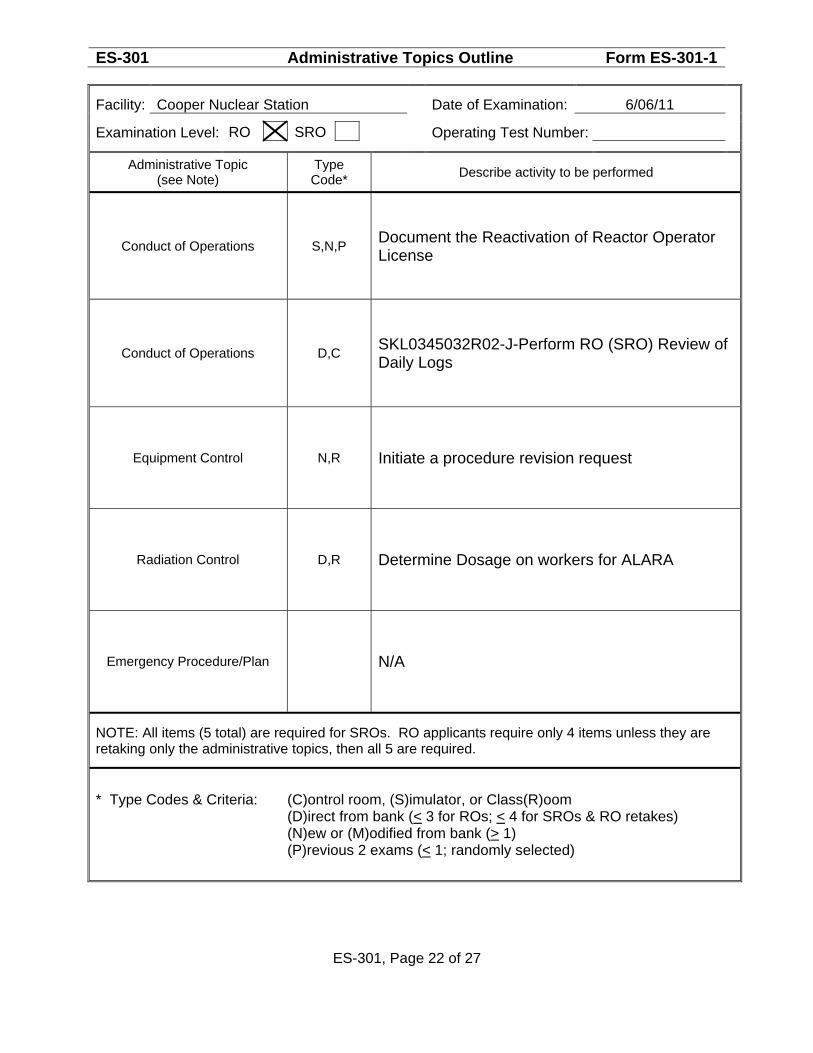
ES-301 Administrative Topics Outline Form ES-301-1
Facility: Cooper Nuclear Station Date of Examination: 6/06/11
Examination Level:
Operating Test Number:
RO SRO
Administrative Topic (see Note)
Type Code* Describe activity to be performed
Conduct of Operations S,N,P Document the Reactivation of Reactor Operator License
Conduct of Operations D,C SKL0345032R02-J-Perform RO (SRO) Review of Daily Logs
Equipment Control N,R Initiate a procedure revision request
Radiation Control D,R Determine Dosage on workers for ALARA
Emergency Procedure/Plan N/A
NOTE: All items (5 total) are required for SROs. RO applicants require only 4 items unless they are retaking only the administrative topics, then all 5 are required.
* Type Codes & Criteria: (C)ontrol room, (S)imulator, or Class(R)oom (D)irect from bank (< 3 for ROs; < 4 for SROs & RO retakes) (N)ew or (M)odified from bank (> 1) (P)revious 2 exams (< 1; randomly selected)
ES-301, Page 22 of 27
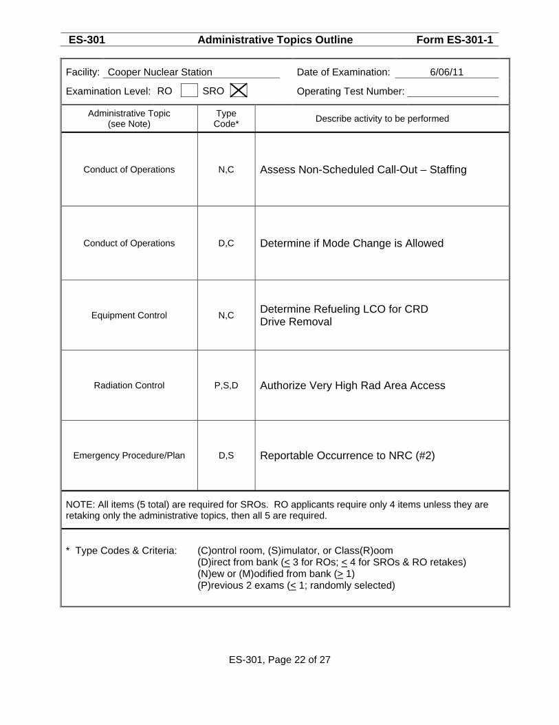
ES-301 Administrative Topics Outline Form ES-301-1
Facility: Cooper Nuclear Station Date of Examination: 6/06/11
Examination Level:
Operating Test Number:
RO SRO
Administrative Topic (see Note)
Type Code* Describe activity to be performed
Conduct of Operations N,C Assess Non-Scheduled Call-Out – Staffing
Conduct of Operations D,C Determine if Mode Change is Allowed
Equipment Control N,C Determine Refueling LCO for CRD Drive Removal
Radiation Control P,S,D Authorize Very High Rad Area Access
Emergency Procedure/Plan D,S Reportable Occurrence to NRC (#2)
NOTE: All items (5 total) are required for SROs. RO applicants require only 4 items unless they are retaking only the administrative topics, then all 5 are required.
* Type Codes & Criteria: (C)ontrol room, (S)imulator, or Class(R)oom (D)irect from bank (< 3 for ROs; < 4 for SROs & RO retakes) (N)ew or (M)odified from bank (> 1) (P)revious 2 exams (< 1; randomly selected)
ES-301, Page 22 of 27
Nebraska Public Power District SKL034-50-XX (XXXXX) Cooper Nuclear Station Page 1 of 4 Job Performance Measure for Operations Revision 00
Task No.: NNNNNNNNNNN RO Reactivation Status Maintenance
Trainee: Examiner: Pass Fail Examiner Signature: Date: ALTERNATE PATH Additional Program Information: 1. Appropriate Performance Locations: Classroom 2. Appropriate Trainee level: RO / SRO / STE 3. Evaluation Method: Perform 4. Performance Time: 10 minutes 5. NRC K/A 2.1.4 (3.3 / 3.8)
Directions to Examiner: 1. This JPM evaluates the trainee’s ability to perform an assessment of their license
reactivation status in accordance with Procedure 2.0.7. 2. All blanks must be filled out with either initials or an “NP” for “not performed”; an
explanation may also be written in the space, if desired, by the examiner. 3. Give the trainee his copy of the Directions to the Trainee (Attachment 1) when ready to
start the JPM. 4. Brief the trainee and tell the trainee to begin. Directions to Trainee: When I tell you to begin, you are to perform an assessment of your license for reactivation in accordance with Procedure 2.0.7. Licensed Operator Active/Reactivation/Medical Status Maintenance Program. Before you start, I will state the general plant conditions, the Initiating Cues, and answer any questions you may have. During task performance, state the actions you are taking, e.g.: repositioning controls and observing instrumentation.
General Conditions: 1. You currently are reactivating your Reactor Operator License 2. You stood a 12 hr shift on the following days, RO 2/20/11 Days; BOP 2/21/11 Days; RO
2/22/2011 Days; RO 2/23/2011 Days: 3. You read the following procedures, 2.0.1; 2.0.2; 2.0.3; 2.0.4; 2.0.9; and 2.0.12.
Nebraska Public Power District SKL034-50-XX (XXXXX) Cooper Nuclear Station Page 2 of 4 Job Performance Measure for Operations Revision 00
Task No.: NNNNNNNNNNN RO Reactivation Status Maintenance
4. You performed a plant tour with an Active SRO on the following days:
o Turbine Building 2/24/11 o Diesel Generator Building 2/24/11 o Intake Structure 2/24/11 o Radwaste Building 2/25/11 o 345 and 161 KV Switchyards 2/25/11 o Control Building 2/25/11 o Augmented Radwaste 2/25/11 o Reactor Building 2/26/11
5. Items Discussed during the tours o Special Diesel Maintenance that occurred while you were inactive. o New Air Compressor Alignment while you were inactive.
General References: 1. Procedure 2.0.7, LICENSED OPERATOR ACTIVE/REACTIVATION/MEDICAL STATUS
MAINTENANCE PROGRAM General Tools and Equipment: 1. None Special Conditions, References, Tools, Equipment: 1. Critical steps denoted by “*”. Task Standards: 1. 100% of critical elements successfully completed without error. 2. 100% of safety and radiological work practices. Initiating Cue(s): The Shift Manager directs you to perform an assessment of your license for reactivation in accordance with Procedure 2.0.7. Licensed Operator Active/Reactivation/Medical Status Maintenance Program. And complete the Attachment 2 and return it to the evaluator.
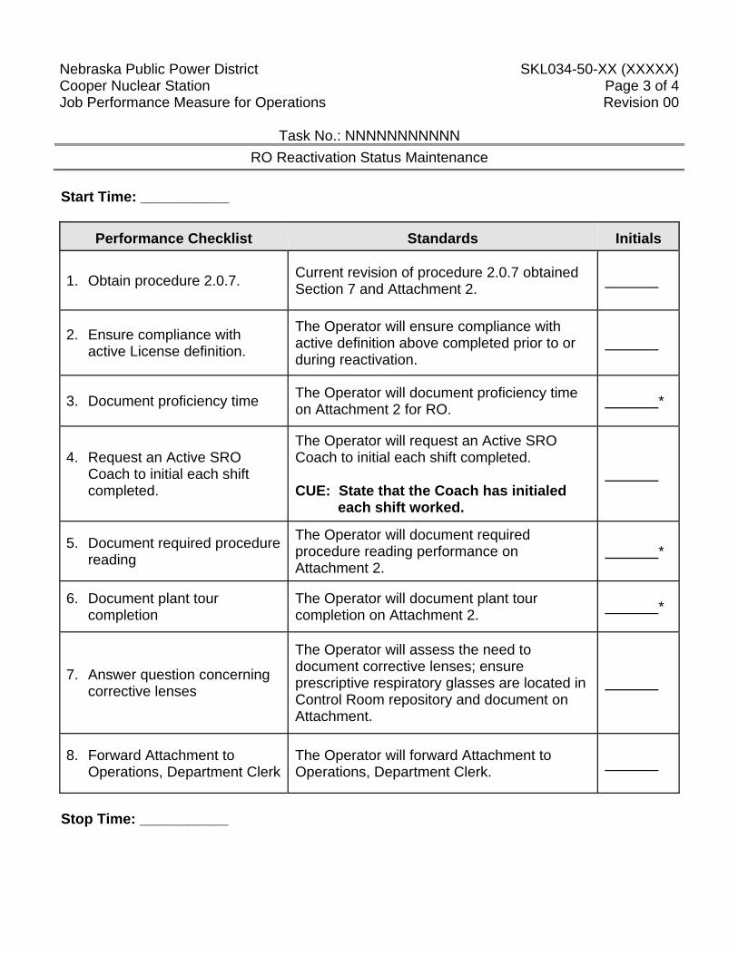
Nebraska Public Power District SKL034-50-XX (XXXXX) Cooper Nuclear Station Page 3 of 4 Job Performance Measure for Operations Revision 00
Task No.: NNNNNNNNNNN RO Reactivation Status Maintenance
Start Time: ___________
Performance Checklist Standards Initials
1. Obtain procedure 2.0.7. Current revision of procedure 2.0.7 obtained Section 7 and Attachment 2.
2. Ensure compliance with active License definition.
The Operator will ensure compliance with active definition above completed prior to or during reactivation.
3. Document proficiency time The Operator will document proficiency time on Attachment 2 for RO. *
4. Request an Active SRO Coach to initial each shift completed.
The Operator will request an Active SRO Coach to initial each shift completed. CUE: State that the Coach has initialed
each shift worked.
5. Document required procedure reading
The Operator will document required procedure reading performance on Attachment 2.
*
6. Document plant tour completion
The Operator will document plant tour completion on Attachment 2. *
7. Answer question concerning corrective lenses
The Operator will assess the need to document corrective lenses; ensure prescriptive respiratory glasses are located in Control Room repository and document on Attachment.
8. Forward Attachment to Operations, Department Clerk
The Operator will forward Attachment to Operations, Department Clerk.
Stop Time: ___________
Nebraska Public Power District SKL034-50-XX (XXXXX) Cooper Nuclear Station Page 4 of 4 Job Performance Measure for Operations Revision 00
ATTACHMENT 1
Directions to Trainee: When I tell you to begin, you are to perform an assessment of your license for reactivation in accordance with Procedure 2.0.7. Licensed Operator Active/Reactivation/Medical Status Maintenance Program. Before you start, I will state the general plant conditions, the Initiating Cues, and answer any questions you may have. During task performance, state the actions you are taking, e.g.: repositioning controls and observing instrumentation.
General Conditions: 1. You currently are reactivating your Reactor Operator License 2. You stood a 12 hr shift on the following days, RO 2/20/11 Days; BOP 2/21/11 Days; RO
2/22/2011 Days; RO 2/23/2011 Days: 3. You read the following procedures, 2.0.1; 2.0.2; 2.0.3; 2.0.4; 2.0.9; and 2.0.12. 4. You performed a plant tour with an Active SRO on the following days:
o Turbine Building 2/24/11 o Diesel Generator Building 2/24/11 o Intake Structure 2/24/11 o Radwaste Building 2/25/11 o 345 and 161 KV Switchyards 2/25/11 o Control Building 2/25/11 o Augmented Radwaste 2/25/11 o Reactor Building 2/26/11
6. Items Discussed during the tours o Special Diesel Maintenance that occurred while you were inactive. o New Air Compressor Alignment while you were inactive.
Initiating Cue(s): The Shift Manager directs you to perform an assessment of your license for reactivation in accordance with Procedure 2.0.7. Licensed Operator Active/Reactivation/Medical Status Maintenance Program. And complete the Attachment 2 and return it to the evaluator.
Nebraska Public Power District SKL034-50-XXXX(XXXXXX) Cooper Nuclear Station Page 1 of 4 Job Performance Measure for Operations Revision 00
Task No.: 299015O0301
Task Title: Perform RO Review of Daily Logs (Alternate Path)
Trainee: Examiner: Pass Fail Examiner Signature: Date: Time Started: ____________ Time Finished: _____________
ALTERNATE PATH Additional Program Information: 1. Appropriate Performance Locations: CR, SIM, EOF 2. Appropriate Trainee level: RO / SRO 3. Evaluation Method: Simulate Perform 4. Performance Time: 10 minutes 5. NRC K/A 2.1.23 (3.9/4.0) Directions to Examiner:
NOTE: THIS IS AN ALTERNATE PATH JPM. THE DIV I TORUS AVERAGE TEMPERATURE WILL EXCEED OPERABILITY LIMITS.
1. This JPM evaluates the trainee's ability to perform an RO review of the daily logs. 2. If this JPM is performed on the Simulator, only the cues preceded by "#" should be given. 3. All blanks must be filled out with either initials or an “NP” for “not performed”; an
explanation may also be written in the space if desired by the examiner. 4. Brief the trainee, place the simulator in run, and tell the trainee to begin. 5. Hand the candidate ATTACHMENT 1.
Directions to Trainee: When I tell you to begin, you are to perform an RO review of the daily logs. Before you start, I will state the general plant conditions, the Initiating Cues and answer any questions you may have. When simulating, physically point to any meters, gauges, recorders and controls you would be using. State the position of controls as you would have manipulated them in order to complete the assigned task.
Nebraska Public Power District SKL034-50-XXXX(XXXXXX) Cooper Nuclear Station Page 2 of 4 Job Performance Measure for Operations Revision 00
Task No.: 299015O0301
Task Title: Perform RO Review of Daily Logs (Alternate Path)
General Conditions: 1. The plant is operating at 100% power. 2. All Channels are operable. 3. The 21:00 readings from PC-TR-24 are:
CH 1 = 97ºF CH 2 = 94ºF CH 3 = 94ºF CH 4 = 98ºF
CH 5 = 93ºF CH 6 = 95ºF CH 7 = 95ºF CH 8 = 96ºF General References: 1. Procedure 6.LOG.601 General Tools and Equipment: 1. None Special Conditions, References, Tools, Equipment: 1. Critical checks denoted by "*". 2. Simulator cues denoted by "#". Task Standards: 1. 100% of critical elements successfully completed without error. 2. 100% of safety and radiological work practices. Initiating Cue(s): You are to fill out Attachment 15, Torus Average Temperature and Drywell Bulk Average Temperature, for Div I, using the data provided and complete an RO review of the log sheet per 6.LOG.601. Inform the CRS when the review is complete.
Nebraska Public Power District SKL034-50-XXXX(XXXXXX) Cooper Nuclear Station Page 3 of 4 Job Performance Measure for Operations Revision 00
Task No.: 299015O0301
Task Title: Perform RO Review of Daily Logs (Alternate Path)
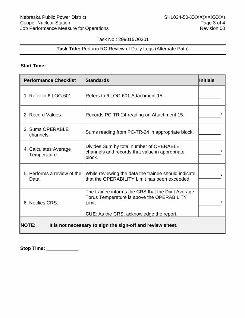
Start Time: ___________
Performance Checklist Standards Initials
1. Refer to 6.LOG.601. Refers to 6.LOG.601 Attachment 15. ________
2. Record Values. Records PC-TR-24 reading on Attachment 15. ________*
3. Sums OPERABLE channels. Sums reading from PC-TR-24 in appropriate block. ________
4. Calculates Average Temperature.
Divides Sum by total number of OPERABLE channels and records that value in appropriate block.
________*
5. Performs a review of the Data.
While reviewing the data the trainee should indicate that the OPERABILITY Limit has been exceeded. ________*
6. Notifies CRS.
The trainee informs the CRS that the Div I Average Torus Temperature is above the OPERABILITY Limit CUE: As the CRS, acknowledge the report.
________*
NOTE: It is not necessary to sign the sign-off and review sheet. Stop Time: ____________
Nebraska Public Power District SKL034-50-XXXX(XXXXXX) Cooper Nuclear Station Page 4 of 4 Job Performance Measure for Operations Revision 00
Task No.: 299015O0301
ATTACHMENT 1 Directions to Trainee: When I tell you to begin, you are to enter the data on the appropriate log sheet and complete the RO review of the daily log. Before you start, I will state the general plant conditions, the Initiating Cues and answer any questions you may have. When simulating, physically point to any meters, gauges, recorders and controls you would be using. State the position of controls as you would have manipulated them in order to complete the assigned task. General Conditions: 1. The plant is operating at 100% power. 2. All Channels are operable. 3. The 21:00 readings from PC-TR-24 are:
CH 1 = 97ºF CH 2 = 94ºF CH 3 = 94ºF CH 4 = 98ºF
CH 5 = 93ºF CH 6 = 95ºF CH 7 = 95ºF CH 8 = 96ºF Initiating Cues: You are to fill out Attachment 15, Torus Average Temperature and Drywell Bulk Average Temperature, for Div I, using the data provided and complete an RO review of the log sheet per 6.LOG.601. Inform the CRS when the review is complete.
Nebraska Public Power District SKL034-50-62 (42651) Cooper Nuclear Station Page 1 of 6 Job Performance Measure for Operations Revision 00
Task No.: Title: Initiate A Procedure Change Request
Trainee: Examiner: Pass Fail Examiner Signature: Date: Additional Program Information: 1. Appropriate Performance Locations: Any location with PC. 2. Appropriate Trainee level: RO / SRO / STE 3. Evaluation Method: Perform 4. Performance Time: 10 minutes 5. NRC K/A 2.2.6 (3.0/3.6)
Directions to Examiner: 1. Create shortcut on desk top where this JPM will be performed. The address is:
http://dev-cnsweb/IDOCS_Sandbox/ 2. This JPM evaluates the trainee’s ability to perform a procedure change request per
04.1IDOCS. 3. All blanks must be filled out with either initials or an “NP” for “not performed”; an
explanation may also be written in the space, if desired, by the examiner. 4. Give the trainee his copy of the Directions to the Trainee (Attachment 2) when ready to
start the JPM. 5. Brief the trainee and tell the trainee to begin. Directions to Trainee: When I tell you to begin, you are to perform A procedure change request Before you start, I will state the general plant conditions, the Initiating Cues, and answer any questions you may have. During task performance, state the actions you are taking, e.g.: repositioning controls and observing instrumentation.
Nebraska Public Power District SKL034-50-62 (42651) Cooper Nuclear Station Page 2 of 6 Job Performance Measure for Operations Revision 00
Task No.: Title: Initiate A Procedure Change Request
General Conditions: 1. A HPCI surveillance has just completed. 2. Suppression Pool temperature has steadied at a peak temperature of 88°F and the CRS
has directed SPC Loop A to be placed in service. General References: 1. 0.4IDOCS, REQUESTING PROCEDURE CHANGE IN IDOCS. General Tools and Equipment: 1. Personal computer. Special Conditions, References, Tools, Equipment: 1. Critical steps denoted by “*”. Task Standards: 1. 100% of critical elements successfully completed without error. 2. 100% of safety and radiological work practices. 3. Values obtained for the dose assessment match those on Attachment 1. Initiating Cue(s): Procedure 2.2.69.3 is being performed and Step 4.22 is the next step to be performed. You realize the step directs closing RHR-MO-34A, SUPPR POOL COOLING INBD THROTTLE VLV vice opening the valve. After notification of the procedure error to the CRS, you are directed to submit a procedure change request per Procedure 4.1IDOCS to get the procedure revised.
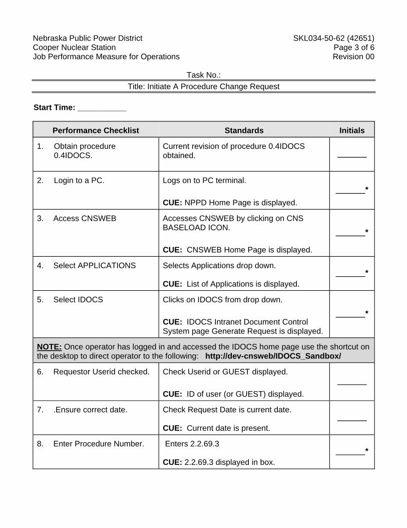
Nebraska Public Power District SKL034-50-62 (42651) Cooper Nuclear Station Page 3 of 6 Job Performance Measure for Operations Revision 00
Task No.: Title: Initiate A Procedure Change Request
Start Time: ___________
Performance Checklist Standards Initials
1. Obtain procedure
0.4IDOCS.
Current revision of procedure 0.4IDOCS obtained.
2. Login to a PC.
Logs on to PC terminal. CUE: NPPD Home Page is displayed.
*
3. Access CNSWEB
Accesses CNSWEB by clicking on CNS BASELOAD ICON. CUE: CNSWEB Home Page is displayed.
*
4. Select APPLICATIONS
Selects Applications drop down. CUE: List of Applications is displayed.
*
5. Select IDOCS
Clicks on IDOCS from drop down. CUE: IDOCS Intranet Document Control System page Generate Request is displayed.
*
NOTE: Once operator has logged in and accessed the IDOCS home page use the shortcut on the desktop to direct operator to the following: http://dev-cnsweb/IDOCS_Sandbox/ 6. Requestor Userid checked.
Check Userid or GUEST displayed. CUE: ID of user (or GUEST) displayed.
7. .Ensure correct date.
Check Request Date is current date. CUE: Current date is present.
8. Enter Procedure Number.
Enters 2.2.69.3 CUE: 2.2.69.3 displayed in box.
*
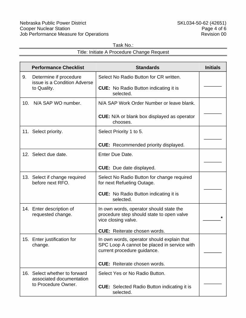
Nebraska Public Power District SKL034-50-62 (42651) Cooper Nuclear Station Page 4 of 6 Job Performance Measure for Operations Revision 00
Task No.: Title: Initiate A Procedure Change Request
Performance Checklist Standards Initials
9. Determine if procedure
issue is a Condition Adverse to Quality.
Select No Radio Button for CR written. CUE: No Radio Button indicating it is
selected.
10. N/A SAP WO number.
N/A SAP Work Order Number or leave blank. CUE: N/A or blank box displayed as operator
chooses.
11. Select priority.
Select Priority 1 to 5. CUE: Recommended priority displayed.
12. Select due date.
Enter Due Date. CUE: Due date displayed.
13. Select if change required
before next RFO.
Select No Radio Button for change required for next Refueling Outage. CUE: No Radio Button indicating it is
selected.
14. Enter description of
requested change.
In own words, operator should state the procedure step should state to open valve vice closing valve. CUE: Reiterate chosen words.
*
15. Enter justification for
change.
In own words, operator should explain that SPC Loop A cannot be placed in service with current procedure guidance. CUE: Reiterate chosen words.
16. Select whether to forward
associated documentation to Procedure Owner.
Select Yes or No Radio Button. CUE: Selected Radio Button indicating it is
selected.
Nebraska Public Power District SKL034-50-62 (42651) Cooper Nuclear Station Page 5 of 6 Job Performance Measure for Operations Revision 00
Task No.: Title: Initiate A Procedure Change Request
Performance Checklist Standards Initials
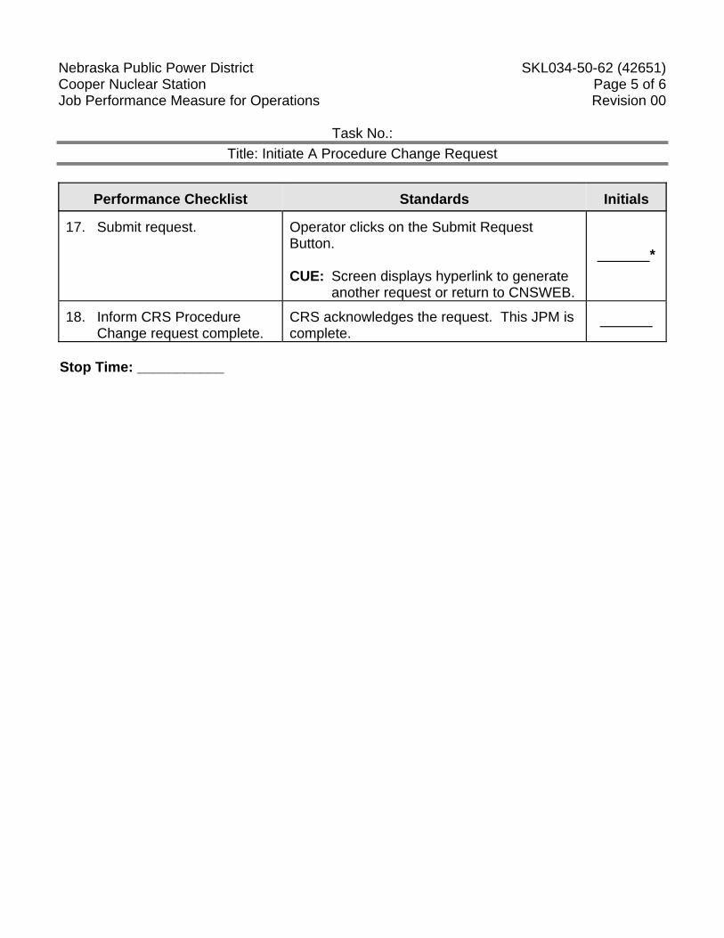
17. Submit request.
Operator clicks on the Submit Request Button. CUE: Screen displays hyperlink to generate
another request or return to CNSWEB.
*
18. Inform CRS Procedure
Change request complete.
CRS acknowledges the request. This JPM is complete.
Stop Time: ___________
Nebraska Public Power District SKL034-50-62 (42651) Cooper Nuclear Station Page 6 of 6 Job Performance Measure for Operations Revision 00
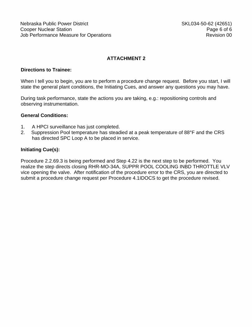
ATTACHMENT 2
Directions to Trainee: When I tell you to begin, you are to perform a procedure change request. Before you start, I will state the general plant conditions, the Initiating Cues, and answer any questions you may have. During task performance, state the actions you are taking, e.g.: repositioning controls and observing instrumentation. General Conditions: 1. A HPCI surveillance has just completed. 2. Suppression Pool temperature has steadied at a peak temperature of 88°F and the CRS
has directed SPC Loop A to be placed in service. Initiating Cue(s): Procedure 2.2.69.3 is being performed and Step 4.22 is the next step to be performed. You realize the step directs closing RHR-MO-34A, SUPPR POOL COOLING INBD THROTTLE VLV vice opening the valve. After notification of the procedure error to the CRS, you are directed to submit a procedure change request per Procedure 4.1IDOCS to get the procedure revised.
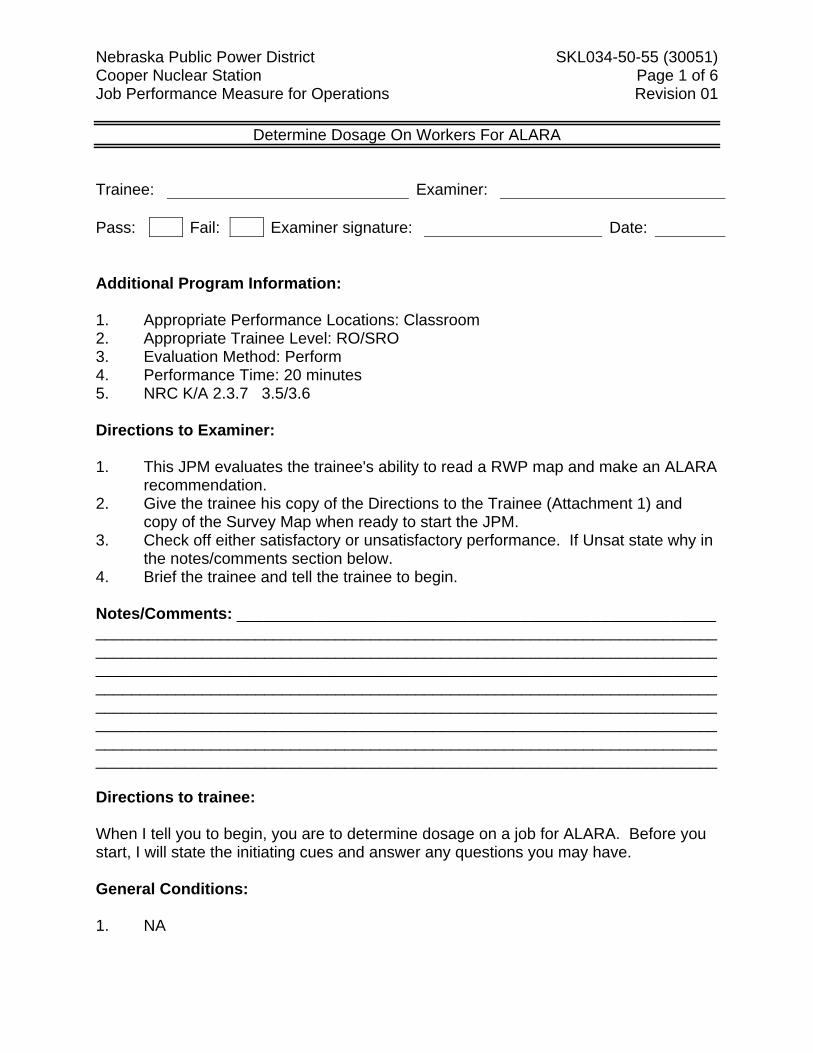
Nebraska Public Power District SKL034-50-55 (30051) Cooper Nuclear Station Page 1 of 6 Job Performance Measure for Operations Revision 01
Determine Dosage On Workers For ALARA
Trainee: Examiner: Pass: Fail: Examiner signature: Date: Additional Program Information: 1. Appropriate Performance Locations: Classroom 2. Appropriate Trainee Level: RO/SRO 3. Evaluation Method: Perform 4. Performance Time: 20 minutes 5. NRC K/A 2.3.7 3.5/3.6 Directions to Examiner: 1. This JPM evaluates the trainee's ability to read a RWP map and make an ALARA
recommendation. 2. Give the trainee his copy of the Directions to the Trainee (Attachment 1) and
copy of the Survey Map when ready to start the JPM. 3. Check off either satisfactory or unsatisfactory performance. If Unsat state why in
the notes/comments section below. 4. Brief the trainee and tell the trainee to begin. Notes/Comments: ______________________________________________________ ______________________________________________________________________ __________________________________________________________________________________________________________________________________________________________________________________________________________________________________________________________________________________________________________________________________________________________________________________________________________________________________________________________________________________________________________ Directions to trainee: When I tell you to begin, you are to determine dosage on a job for ALARA. Before you start, I will state the initiating cues and answer any questions you may have. General Conditions: 1. NA
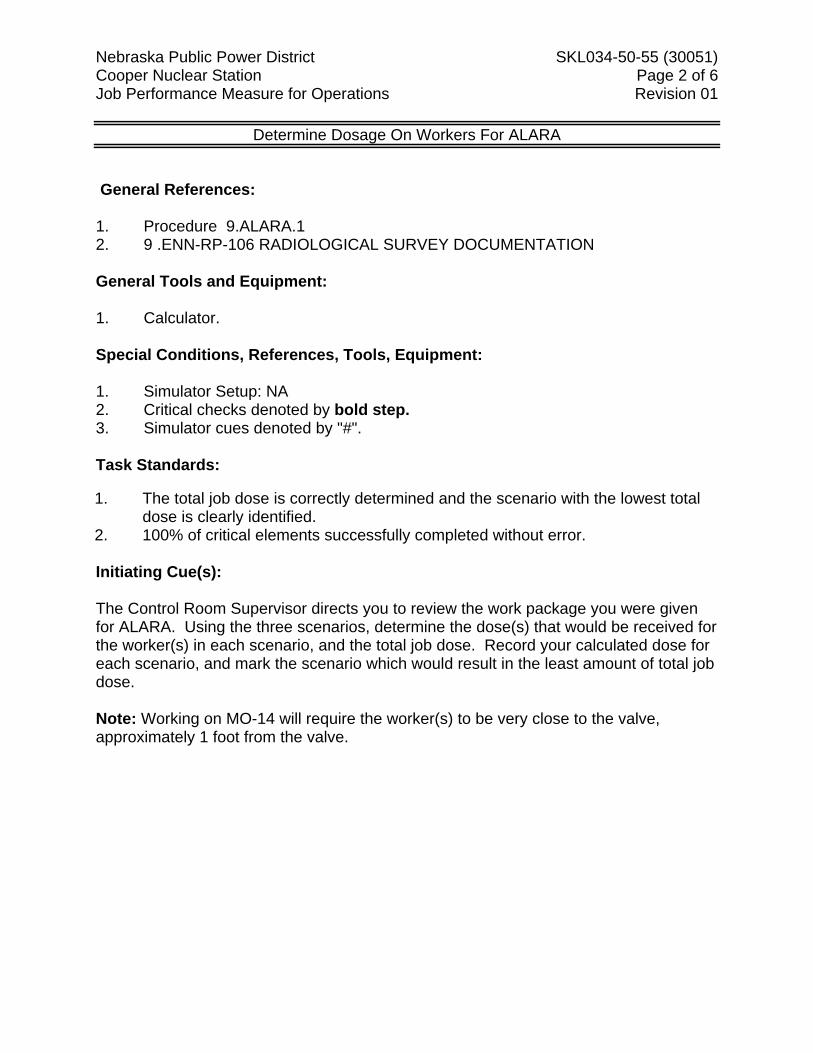
Nebraska Public Power District SKL034-50-55 (30051) Cooper Nuclear Station Page 2 of 6 Job Performance Measure for Operations Revision 01
Determine Dosage On Workers For ALARA
General References: 1. Procedure 9.ALARA.1 2. 9 .ENN-RP-106 RADIOLOGICAL SURVEY DOCUMENTATION General Tools and Equipment: 1. Calculator. Special Conditions, References, Tools, Equipment: 1. Simulator Setup: NA 2. Critical checks denoted by bold step. 3. Simulator cues denoted by "#". Task Standards: 1. The total job dose is correctly determined and the scenario with the lowest total
dose is clearly identified. 2. 100% of critical elements successfully completed without error. Initiating Cue(s): The Control Room Supervisor directs you to review the work package you were given for ALARA. Using the three scenarios, determine the dose(s) that would be received for the worker(s) in each scenario, and the total job dose. Record your calculated dose for each scenario, and mark the scenario which would result in the least amount of total job dose. Note: Working on MO-14 will require the worker(s) to be very close to the valve, approximately 1 foot from the valve.
Nebraska Public Power District SKL034-50-55 (30051) Cooper Nuclear Station Page 3 of 6 Job Performance Measure for Operations Revision 01
Determine Dosage On Workers For ALARA
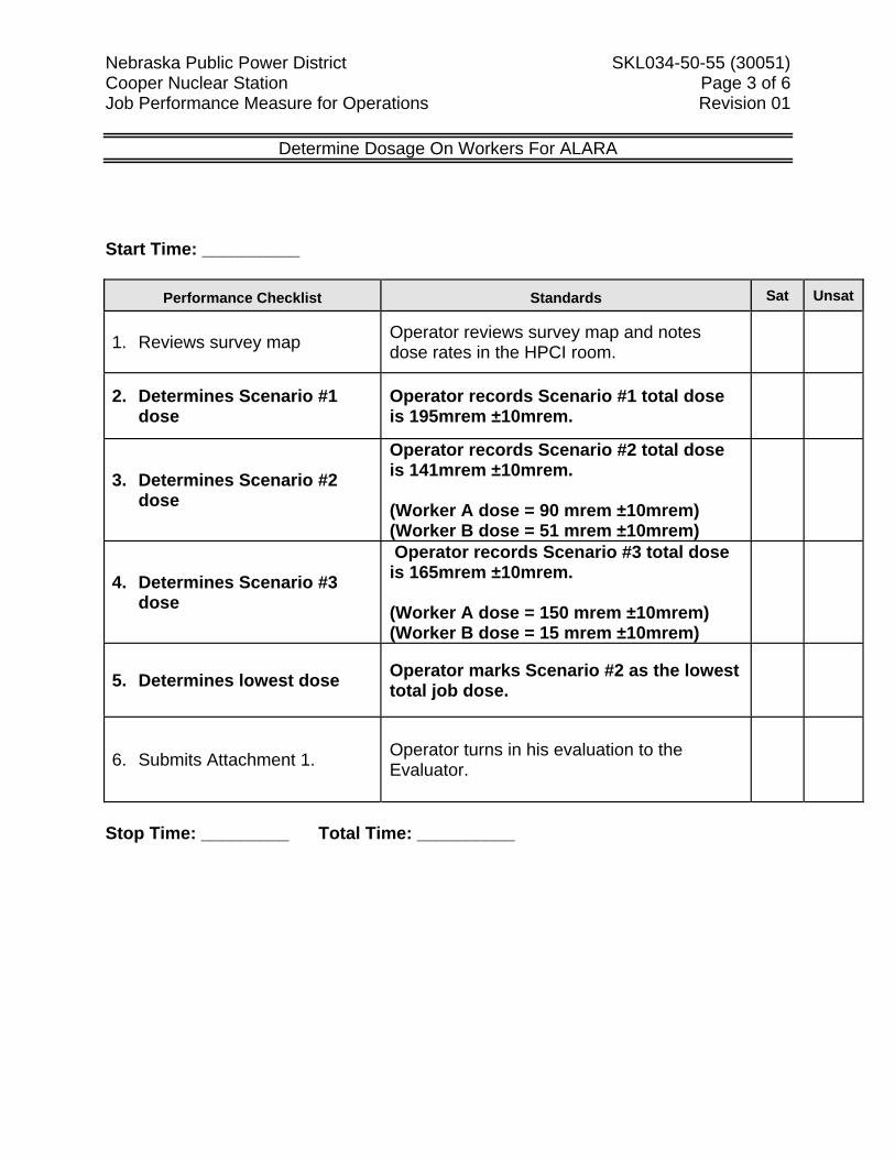
Start Time: __________
Performance Checklist Standards Sat Unsat
1. Reviews survey map Operator reviews survey map and notes dose rates in the HPCI room.
2. Determines Scenario #1 dose
Operator records Scenario #1 total dose is 195mrem ±10mrem.
3. Determines Scenario #2 dose
Operator records Scenario #2 total dose is 141mrem ±10mrem. (Worker A dose = 90 mrem ±10mrem) (Worker B dose = 51 mrem ±10mrem)
4. Determines Scenario #3 dose
Operator records Scenario #3 total dose is 165mrem ±10mrem. (Worker A dose = 150 mrem ±10mrem) (Worker B dose = 15 mrem ±10mrem)
5. Determines lowest dose Operator marks Scenario #2 as the lowest total job dose.
6. Submits Attachment 1. Operator turns in his evaluation to the Evaluator.
Stop Time: _________ Total Time: __________
Nebraska Public Power District SKL034-50-55 (30051) Cooper Nuclear Station Page 4 of 6 Job Performance Measure for Operations Revision 01
Determine Dosage On Workers For ALARA
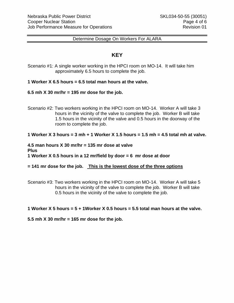
KEY Scenario #1: A single worker working in the HPCI room on MO-14. It will take him
approximately 6.5 hours to complete the job. 1 Worker X 6.5 hours = 6.5 total man hours at the valve. 6.5 mh X 30 mr/hr = 195 mr dose for the job. Scenario #2: Two workers working in the HPCI room on MO-14. Worker A will take 3
hours in the vicinity of the valve to complete the job. Worker B will take 1.5 hours in the vicinity of the valve and 0.5 hours in the doorway of the room to complete the job.
1 Worker X 3 hours = 3 mh + 1 Worker X 1.5 hours = 1.5 mh = 4.5 total mh at valve. 4.5 man hours X 30 mr/hr = 135 mr dose at valve Plus 1 Worker X 0.5 hours in a 12 mr/field by door = 6 mr dose at door = 141 mr dose for the job. This is the lowest dose of the three options Scenario #3: Two workers working in the HPCI room on MO-14. Worker A will take 5
hours in the vicinity of the valve to complete the job. Worker B will take 0.5 hours in the vicinity of the valve to complete the job.
1 Worker X 5 hours = 5 + 1Worker X 0.5 hours = 5.5 total man hours at the valve. 5.5 mh X 30 mr/hr = 165 mr dose for the job.
Nebraska Public Power District SKL034-50-55 (30051) Cooper Nuclear Station Page 5 of 6 Job Performance Measure for Operations Revision 01
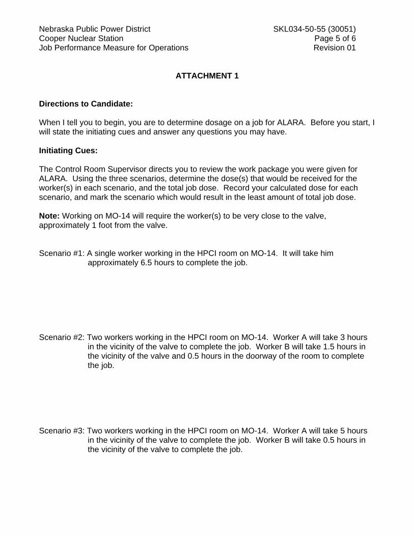
ATTACHMENT 1 Directions to Candidate: When I tell you to begin, you are to determine dosage on a job for ALARA. Before you start, I will state the initiating cues and answer any questions you may have. Initiating Cues: The Control Room Supervisor directs you to review the work package you were given for ALARA. Using the three scenarios, determine the dose(s) that would be received for the worker(s) in each scenario, and the total job dose. Record your calculated dose for each scenario, and mark the scenario which would result in the least amount of total job dose. Note: Working on MO-14 will require the worker(s) to be very close to the valve, approximately 1 foot from the valve. Scenario #1: A single worker working in the HPCI room on MO-14. It will take him
approximately 6.5 hours to complete the job. Scenario #2: Two workers working in the HPCI room on MO-14. Worker A will take 3 hours
in the vicinity of the valve to complete the job. Worker B will take 1.5 hours in the vicinity of the valve and 0.5 hours in the doorway of the room to complete the job.
Scenario #3: Two workers working in the HPCI room on MO-14. Worker A will take 5 hours
in the vicinity of the valve to complete the job. Worker B will take 0.5 hours in the vicinity of the valve to complete the job.
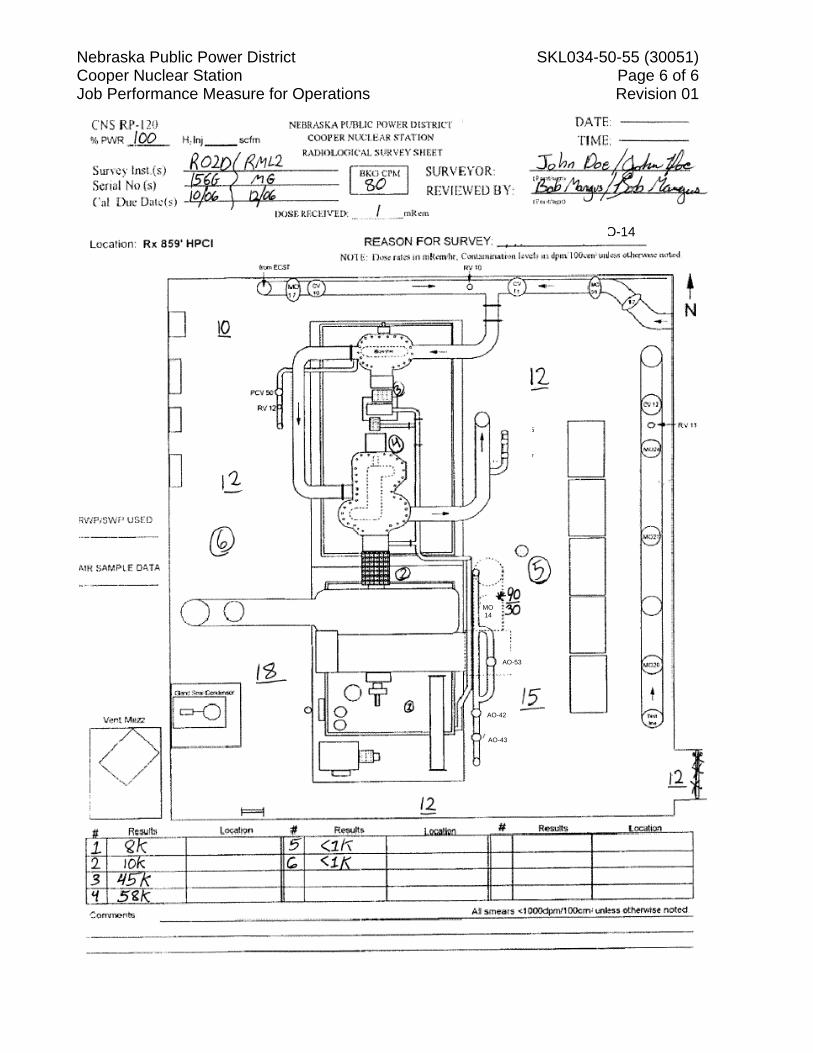
Nebraska PCooper NuJob Perform
Public Powuclear Statiomance Mea
er District on asure for Operations
MO 14
Work
AO-53
AO-42
AO-43
CV-17
MO-25
SKL034-50
k on HPCI-MO
7
5
0-55 (3005Page 6 ofRevision 0
O-14
1) f 6 01
Nebraska Public Power District SKL034-50-XX(XXXXXX) Cooper Nuclear Station Page 1 of 4 Job Performance Measure for Operations Revision 00
Task No.: 299015O0301 Task Title: Assess Non-Scheduled Call-Out
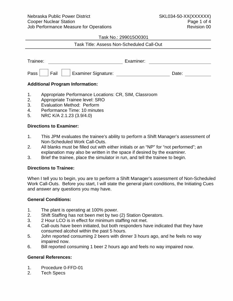
Trainee: Examiner: Pass Fail Examiner Signature: Date: Additional Program Information: 1. Appropriate Performance Locations: CR, SIM, Classroom 2. Appropriate Trainee level: SRO 3. Evaluation Method: Perform 4. Performance Time: 10 minutes 5. NRC K/A 2.1.23 (3.9/4.0) Directions to Examiner: 1. This JPM evaluates the trainee's ability to perform a Shift Manager’s assessment of
Non-Scheduled Work Call-Outs. 2. All blanks must be filled out with either initials or an “NP” for “not performed”; an
explanation may also be written in the space if desired by the examiner. 3. Brief the trainee, place the simulator in run, and tell the trainee to begin. Directions to Trainee: When I tell you to begin, you are to perform a Shift Manager’s assessment of Non-Scheduled Work Call-Outs. Before you start, I will state the general plant conditions, the Initiating Cues and answer any questions you may have. General Conditions: 1. The plant is operating at 100% power. 2. Shift Staffing has not been met by two (2) Station Operators. 3. 2 Hour LCO is in effect for minimum staffing not met. 4. Call-outs have been initiated, but both responders have indicated that they have
consumed alcohol within the past 5 hours. 5. John reported consuming 2 beers with dinner 3 hours ago, and he feels no way
impaired now. 6. Bill reported consuming 1 beer 2 hours ago and feels no way impaired now.
General References: 1. Procedure 0-FFD-01 2. Tech Specs
Nebraska Public Power District SKL034-50-XX(XXXXXX) Cooper Nuclear Station Page 2 of 4 Job Performance Measure for Operations Revision 00
Task No.: 299015O0301 Task Title: Assess Non-Scheduled Call-Out
General Tools and Equipment: 1. None Special Conditions, References, Tools, Equipment: 1. Critical checks denoted by "*". 2. Simulator cues denoted by "#". Task Standards: 1. 100% of critical elements successfully completed without error. 2. 100% of safety and radiological work practices. Initiating Cue(s): You are to perform a Shift Manager’s assessment of 0-FFD-01 Non-Scheduled Work Call-Outs, and determine applicable actions based upon your review. Inform the evaluator when you have completed your assessment.
Nebraska Public Power District SKL034-50-XX(XXXXXX) Cooper Nuclear Station Page 3 of 4 Job Performance Measure for Operations Revision 00
Task No.: 299015O0301 Task Title: Assess Non-Scheduled Call-Out
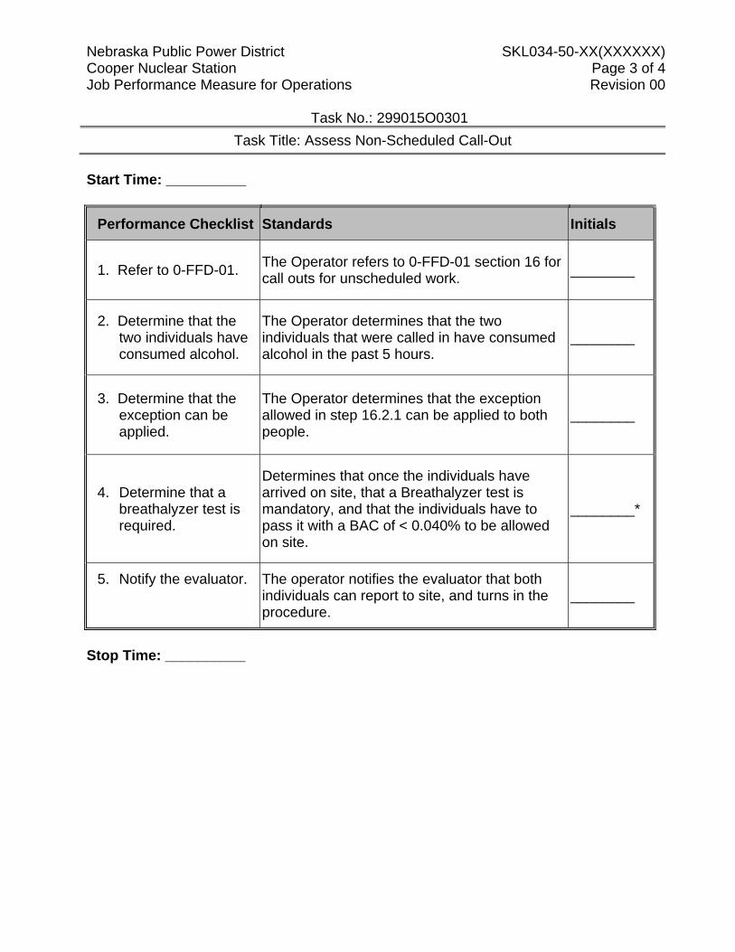
Start Time: __________
Performance Checklist Standards Initials
1. Refer to 0-FFD-01. The Operator refers to 0-FFD-01 section 16 for call outs for unscheduled work. ________
2. Determine that the two individuals have consumed alcohol.
The Operator determines that the two individuals that were called in have consumed alcohol in the past 5 hours.
________
3. Determine that the exception can be applied.
The Operator determines that the exception allowed in step 16.2.1 can be applied to both people.
________
4. Determine that a breathalyzer test is required.
Determines that once the individuals have arrived on site, that a Breathalyzer test is mandatory, and that the individuals have to pass it with a BAC of < 0.040% to be allowed on site.
________*
5. Notify the evaluator.
The operator notifies the evaluator that both individuals can report to site, and turns in the procedure.
________
Stop Time: __________
Nebraska Public Power District SKL034-50-XX(XXXXXX) Cooper Nuclear Station Page 4 of 4 Job Performance Measure for Operations Revision 00
Task No.: 299015O0301 Task Title: SKL03450XXR00-J-Assess Non-Scheduled Call-Out
ATTACHMENT 1 Directions to Trainee: When I tell you to begin, you are to perform a Shift Manager’s assessment of Non-Scheduled Work Call-Outs. Before you start, I will state the general plant conditions, the Initiating Cues and answer any questions you may have. General Conditions: 7. The plant is operating at 100% power. 8. Shift Staffing has not been met by two (2) Station Operators. 9. 2 Hour LCO is in effect for minimum staffing not met. 10. Call-outs have been initiated, but both responders have indicated that they have
consumed alcohol within the past 5 hours. 11. John reported consuming 2 beers with dinner 3 hours ago, and he feels no way
impaired now. 12. Bill reported consuming 1 beer 2 hours ago and feels no way impaired now.
You are to perform a Shift Manager’s assessment of 0-FFD-01 Non-Scheduled Work Call-Outs, and determine applicable actions based upon your review. Inform the evaluator when you have completed your assessment.
Nebraska Public Power District SKL034-50-XX (XXXXX) Cooper Nuclear Station Page 1 of 6 Job Performance Measure for Operations Revision 00
Task No.: NNNNNNNNNNN Title: Determine if Mode Change is Allowed
Trainee: Examiner: Pass Fail Examiner Signature: Date: Additional Program Information: 1. Appropriate Performance Locations: SIM or Classroom 2. Appropriate Trainee level: SRO / STE 3. Evaluation Method: Perform 4. Performance Time: 10 minutes 5. NRC K/A Directions to Examiner: 1. This JPM evaluates the trainee’s ability to determine if a Reactor Mode change is allowed
in accordance with Tech Specs 2. All blanks must be filled out with either initials or an “NP” for “not performed”; an
explanation may also be written in the space, if desired, by the examiner. 3. Give the trainee his copy of the Directions to the Trainee (Attachment 2) when ready to
start the JPM. 4. Brief the trainee and tell the trainee to begin. Directions to Trainee: When I tell you to begin, you are to determine if a Reactor Mode change is allowed in accordance with Tech Specs. Before you start, I will state the general plant conditions, the Initiating Cues, and answer any questions you may have. During task performance, state the actions you are taking, e.g.: repositioning controls and observing instrumentation.
Nebraska Public Power District SKL034-50-XX (XXXXX) Cooper Nuclear Station Page 2 of 6 Job Performance Measure for Operations Revision 00
Task No.: NNNNNNNNNNN Title: Determine if Mode Change is Allowed
General Conditions: 1. The Plant is in MODE 3 with Reactor Pressure 600 psig. 2. RCIC is inoperable and is in day 10 of a 14 day LCO. General References: 1. Tech Specs General Tools and Equipment: 1. None Special Conditions, References, Tools, Equipment: 1. Critical steps denoted by “*”. Task Standards: 1. 100% of critical elements successfully completed without error. 2. 100% of safety and radiological work practices. Initiating Cue(s): You are the Shift Manager and need to determine if a Reactor Mode change to MODE 2 allowed in accordance with Tech Specs provided with the inoperable equipment in the General Conditions list, provided. Provide the answer on Attachment 2 and present it to the examiner when complete.
Nebraska Public Power District SKL034-50-XX (XXXXX) Cooper Nuclear Station Page 3 of 6 Job Performance Measure for Operations Revision 00
Task No.: NNNNNNNNNNN Title: Determine if Mode Change is Allowed
Start Time: ___________
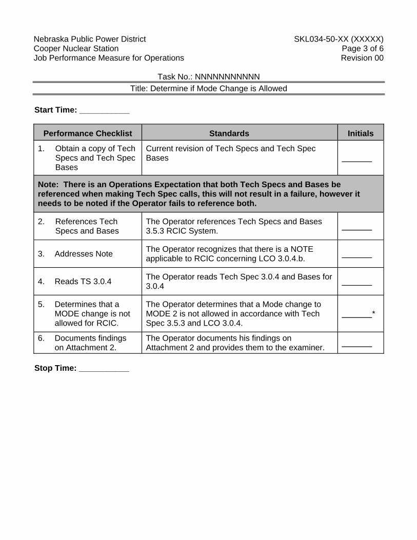
Performance Checklist Standards Initials
1. Obtain a copy of Tech Specs and Tech Spec Bases
Current revision of Tech Specs and Tech Spec Bases
Note: There is an Operations Expectation that both Tech Specs and Bases be referenced when making Tech Spec calls, this will not result in a failure, however it needs to be noted if the Operator fails to reference both.
2. References Tech Specs and Bases
The Operator references Tech Specs and Bases 3.5.3 RCIC System.
3. Addresses Note The Operator recognizes that there is a NOTE applicable to RCIC concerning LCO 3.0.4.b.
4. Reads TS 3.0.4 The Operator reads Tech Spec 3.0.4 and Bases for 3.0.4
5. Determines that a MODE change is not allowed for RCIC.
The Operator determines that a Mode change to MODE 2 is not allowed in accordance with Tech Spec 3.5.3 and LCO 3.0.4.
*
6. Documents findings on Attachment 2.
The Operator documents his findings on Attachment 2 and provides them to the examiner.
Stop Time: ___________
Nebraska Public Power District SKL034-50-XX (XXXXX) Cooper Nuclear Station Page 4 of 6 Job Performance Measure for Operations Revision 00
Task No.: NNNNNNNNNNN Title: Determine if Mode Change is Allowed
ATTACHMENT 1
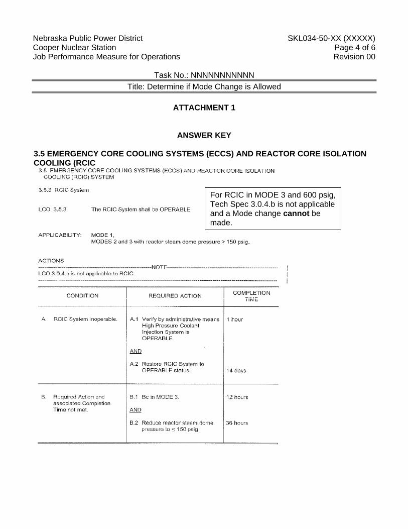
ANSWER KEY 3.5 EMERGENCY CORE COOLING SYSTEMS (ECCS) AND REACTOR CORE ISOLATION COOLING (RCIC
For RCIC in MODE 3 and 600 psig, Tech Spec 3.0.4.b is not applicable and a Mode change cannot be made.
Nebraska Public Power District SKL034-50-XX (XXXXX) Cooper Nuclear Station Page 5 of 6 Job Performance Measure for Operations Revision 00 ATTACHMENT 1 Directions to Trainee: When I tell you to begin, you are to determine if a Reactor Mode change is allowed in accordance with Tech Specs. Before you start, I will state the general plant conditions, the Initiating Cues, and answer any questions you may have. During task performance, state the actions you are taking, e.g.: repositioning controls and observing instrumentation. General Conditions: 1. The Plant is in MODE 4. 2. RCIC is inoperable and is in day 10 of a 14 day LCO.
Initiating Cue(s): You are the Shift Manager and need to determine if a Reactor Mode change is allowed in accordance with Tech Specs provided with the inoperable equipment in the General Conditions list, provided. Provide the answer on Attachment 2 and present it to the examiner when complete.
Nebraska Public Power District SKL034-50-XX (XXXXX) Cooper Nuclear Station Page 6 of 6 Job Performance Measure for Operations Revision 00
ATTACHMENT 2
_____________________________________ Signature
Nebraska Public Power District SKL034-50-61 (41927) Cooper Nuclear Station Page 1 of 6 Job Performance Measure for Operations Revision 00
Task No.: 341030W0303
Determine Required Tech Specs Actions for Removal of a Single CRD During Refueling
Trainee: Examiner: Pass Fail Examiner Signature: Date: Additional Program Information: 1. Appropriate Performance Locations: Any location 2. Appropriate Trainee level: SRO / STE 3. Evaluation Method: Perform 4. Performance Time: 10 minutes 5. 2.2.40 (SRO 4.7)
Directions to Examiner: 1. This JPM evaluates the trainee’s ability to determine the Control Rods associated with a
5X5 array during a single CRD Removal during Refueling in accordance with Tech Specs 3.10.5.
2. All blanks must be filled out with either initials or an “NP” for “not performed”; an explanation may also be written in the space, if desired, by the examiner.
3. Give the trainee his copy of the Directions to the Trainee (Attachment 2) when ready to start the JPM.
4. Brief the trainee and tell the trainee to begin. Directions to Trainee: When I tell you to begin, you are to determine the requirements for the removal of CRD 38-19 during Refueling in accordance with Technical Specification. Before you start, I will state the general plant conditions, the Initiating Cues, and answer any questions you may have. During task performance, state the actions you are taking, e.g.: repositioning controls and observing instrumentation.
Nebraska Public Power District SKL034-50-61 (41927) Cooper Nuclear Station Page 2 of 6 Job Performance Measure for Operations Revision 00
Task No.: 341030W0303
Determine Required Tech Specs Actions for Removal of a Single CRD During Refueling
General Conditions: 1. The Reactor is in MODE 5 (Refuel) 2. Each control rod cell contains fuel 3. All Control Rods are fully inserted in the vessel General References: 1. Technical Specifications 3.10.5 General Tools and Equipment: 1. None Special Conditions, References, Tools, Equipment: 1. Critical steps denoted by “*”. Task Standards: 1. 100% of critical elements successfully completed without error. 2. 100% of safety and radiological work practices. Initiating Cue(s): The Shift Manager directs you to determine the requirements for the removal of CRD 38-19 during Refueling in accordance with Technical Specification. On Attachment 3 provided, write those requirements and indicate on the core map any effected control rods.
.
Nebraska Public Power District SKL034-50-61 (41927) Cooper Nuclear Station Page 3 of 6 Job Performance Measure for Operations Revision 00
Task No.: 341030W0303
Determine Required Tech Specs Actions for Removal of a Single CRD During Refueling
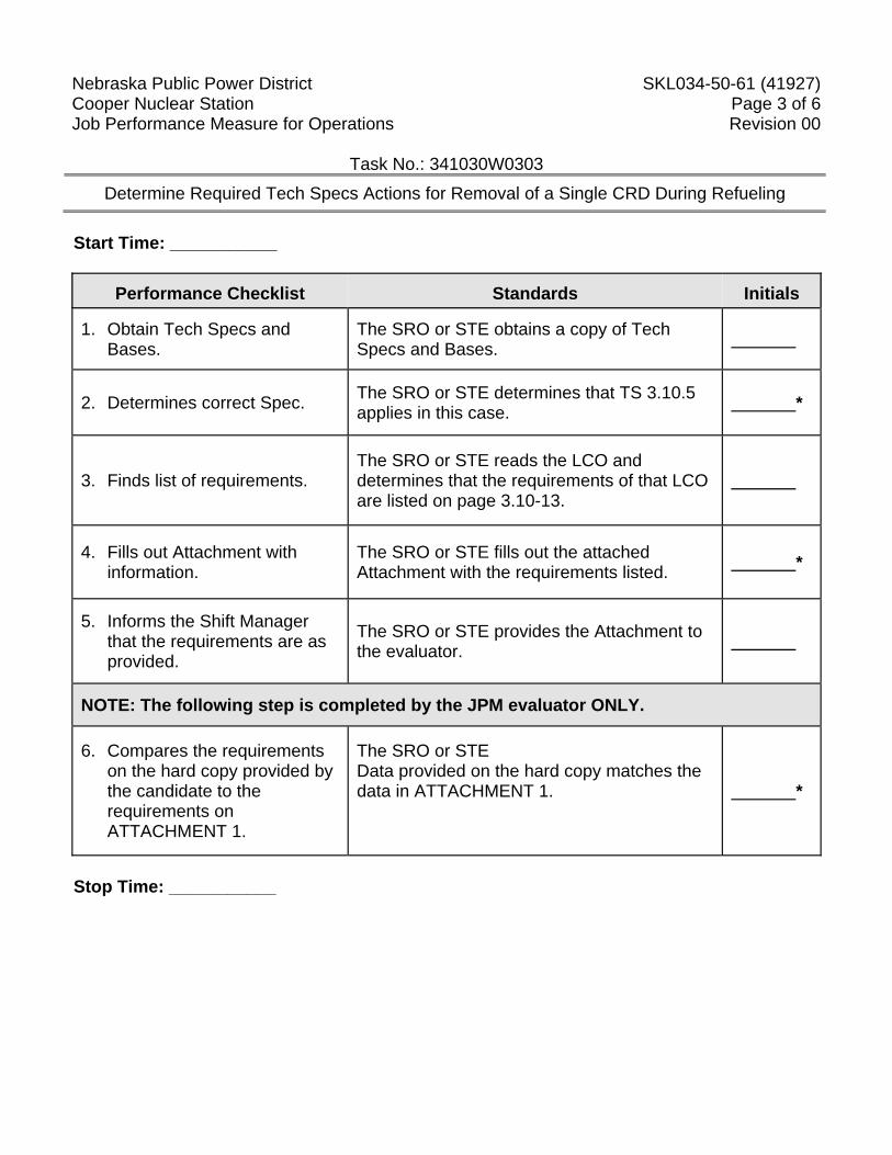
Start Time: ___________
Performance Checklist Standards Initials
1. Obtain Tech Specs and Bases.
The SRO or STE obtains a copy of Tech Specs and Bases.
2. Determines correct Spec. The SRO or STE determines that TS 3.10.5 applies in this case. *
3. Finds list of requirements. The SRO or STE reads the LCO and determines that the requirements of that LCO are listed on page 3.10-13.
4. Fills out Attachment with information.
The SRO or STE fills out the attached Attachment with the requirements listed. *
5. Informs the Shift Manager that the requirements are as provided.
The SRO or STE provides the Attachment to the evaluator.
NOTE: The following step is completed by the JPM evaluator ONLY.
6. Compares the requirements on the hard copy provided by the candidate to the requirements on ATTACHMENT 1.
The SRO or STE Data provided on the hard copy matches the data in ATTACHMENT 1.
*
Stop Time: ___________
Nebraska Public Power District SKL034-50-61 (41927) Cooper Nuclear Station Page 4 of 6 Job Performance Measure for Operations Revision 00
Task No.: 341030W0303
Determine Required Tech Specs Actions for Removal of a Single CRD During Refueling
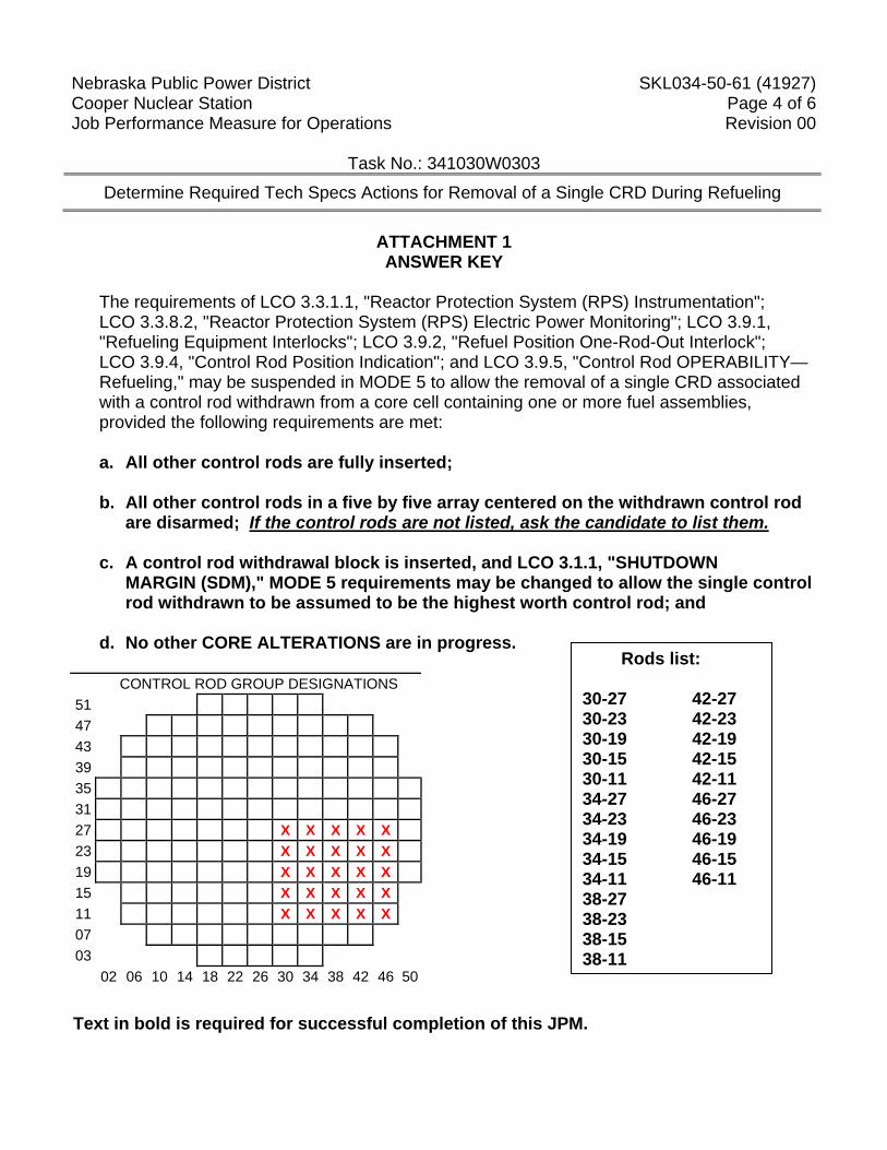
ATTACHMENT 1 ANSWER KEY
The requirements of LCO 3.3.1.1, "Reactor Protection System (RPS) Instrumentation"; LCO 3.3.8.2, "Reactor Protection System (RPS) Electric Power Monitoring"; LCO 3.9.1, "Refueling Equipment Interlocks"; LCO 3.9.2, "Refuel Position One-Rod-Out Interlock"; LCO 3.9.4, "Control Rod Position Indication"; and LCO 3.9.5, "Control Rod OPERABILITY—Refueling," may be suspended in MODE 5 to allow the removal of a single CRD associated with a control rod withdrawn from a core cell containing one or more fuel assemblies, provided the following requirements are met: a. All other control rods are fully inserted; b. All other control rods in a five by five array centered on the withdrawn control rod
are disarmed; If the control rods are not listed, ask the candidate to list them. c. A control rod withdrawal block is inserted, and LCO 3.1.1, "SHUTDOWN
MARGIN (SDM)," MODE 5 requirements may be changed to allow the single control rod withdrawn to be assumed to be the highest worth control rod; and
d. No other CORE ALTERATIONS are in progress.
Text in bold is required for successful completion of this JPM.
CONTROL ROD GROUP DESIGNATIONS 51 47 43 39 35 31 27 X X X X X 23 X X X X X 19 X X X X X 15 X X X X X 11 X X X X X 07 03 02 06 10 14 18 22 26 30 34 38 42 46 50
Rods list: 30-27 42-27 30-23 42-23 30-19 42-19 30-15 42-15 30-11 42-11 34-27 46-27 34-23 46-23 34-19 46-19 34-15 46-15 34-11 46-11 38-27 38-23 38-15 38-11
Nebraska Public Power District SKL034-50-61 (41927) Cooper Nuclear Station Page 5 of 6 Job Performance Measure for Operations Revision 00
ATTACHMENT 2
Directions to Trainee: When I tell you to begin, you are to determine the requirements for the removal of CRD 38-19 during Refueling in accordance with Technical Specification. Before you start, I will state the general plant conditions, the Initiating Cues, and answer any questions you may have. During task performance, state the actions you are taking, e.g.: repositioning controls and observing instrumentation. General Conditions: 1. The Reactor is in MODE 5 (Refuel) 2. Each control rod cell contains fuel 3. All Control Rods are fully inserted in the vessel Initiating Cue(s): The Shift Manager directs you to determine the requirements for the removal of CRD 38-19 during Refueling in accordance with Technical Specification. On Attachment 3 provided, write those requirements and indicate on the core map any effected control rods.
Nebraska Public Power District SKL034-50-61 (41927) Cooper Nuclear Station Page 6 of 6 Job Performance Measure for Operations Revision 00
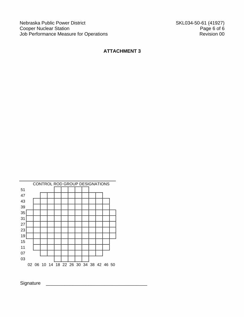
ATTACHMENT 3
Signature ______________________________________
CONTROL ROD GROUP DESIGNATIONS 51 47 43 39 35 31 27 23 19 15 11 07 03 02 06 10 14 18 22 26 30 34 38 42 46 50
Nebraska Public Power District SKL034-50-63 (42802) Cooper Nuclear Station Page 1 of 16 Job Performance Measure for Operations Revision 00
Task No.: Title: Authorize Very High Radiation Access
Trainee: Examiner: Pass Fail Examiner Signature: Date: Additional Program Information: 1. Appropriate Performance Locations: Classroom 2. Appropriate Trainee level: SRO / STE 3. Evaluation Method: Perform 4. Performance Time: 10 minutes 5. NRC K/A 2.3.12 (3.2/3.7)
Directions to Examiner: 1. This JPM evaluates the trainee’s ability to authorize very high radiation access per 9.EN-
RP-101. 2. All blanks must be filled out with either initials or an “NP” for “not performed”; an
explanation may also be written in the space, if desired, by the examiner. 3. Give the trainee his copy of the Directions to the Trainee (Attachment 2) when ready to
start the JPM. 4. Brief the trainee and tell the trainee to begin. Directions to Trainee: When I tell you to begin, you are to determine whether to authorize very high radiation access per 9.EN-RP-101. Before you start, I will state the general plant conditions, the Initiating Cues, and answer any questions you may have. During task performance, state the actions you are taking, e.g.: repositioning controls and observing instrumentation.
Nebraska Public Power District SKL034-50-63 (42802) Cooper Nuclear Station Page 2 of 16 Job Performance Measure for Operations Revision 00
Task No.: Title: Authorize Very High Radiation Access
General Conditions: 1. A small EH piping leak has propagated in on the west side near the main turbine front
standard. 2. Plans are in place to have maintenance place a clamp over the piping as a temporary fix to
the leak. 3. The area has been posted as a VERY HIGH RADIATION AREA. 4. Risk has been assessed and no other alternative is available. General References: 1. Procedure 9.EN-RP-101, Access Control For Radiologically Controlled Areas General Tools and Equipment: 1. None Special Conditions, References, Tools, Equipment: 1. Critical steps denoted by “*”. Task Standards: 1. 100% of critical elements successfully completed without error. 2. 100% of safety and radiological work practices. 3. Values obtained for the dose assessment match those on Attachment 1. Initiating Cue(s): As the on-watch Shift Manager you are to review the provided information and determine if you can approve access into the very high radiation area to perform the task.
Nebraska Public Power District SKL034-50-63 (42802) Cooper Nuclear Station Page 3 of 16 Job Performance Measure for Operations Revision 00
Task No.: Title: Authorize Very High Radiation Access
Start Time: ___________
Performance Checklist Standards Initials
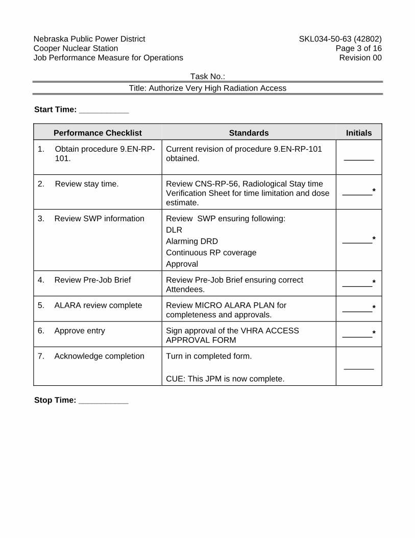
1. Obtain procedure 9.EN-RP-
101.
Current revision of procedure 9.EN-RP-101 obtained.
2. Review stay time.
Review CNS-RP-56, Radiological Stay time Verification Sheet for time limitation and dose estimate.
*
3. Review SWP information
Review SWP ensuring following: DLR Alarming DRD Continuous RP coverage Approval
*
4. Review Pre-Job Brief
Review Pre-Job Brief ensuring correct Attendees.
*
5. ALARA review complete
Review MICRO ALARA PLAN for completeness and approvals.
*
6. Approve entry
Sign approval of the VHRA ACCESS APPROVAL FORM
*
7. Acknowledge completion
Turn in completed form. CUE: This JPM is now complete.
Stop Time: ___________
Nebraska Public Power District SKL034-50-63 (42802) Cooper Nuclear Station Page 4 of 16 Job Performance Measure for Operations Revision 00
ATTACHMENT 1
Directions to Trainee: When I tell you to begin, you are to determine whether to authorize very high radiation access per 9.EN-RP-101. Before you start, I will state the general plant conditions, the Initiating Cues, and answer any questions you may have. During task performance, state the actions you are taking, e.g.: repositioning controls and observing instrumentation. General Conditions: 1. A small EH piping leak has propagated in on the west side near the main turbine front
standard. 2. Plans are in place to have maintenance place a clamp over the piping as a temporary fix to
the leak. 3. The area has been posted as a VERY HIGH RADIATION AREA. 4. Risk has been assessed and no other alternative is available. Initiating Cue(s): As the on-watch Shift Manager you are to review the provided information and determine if you can approve access into the very high radiation area to perform the task.
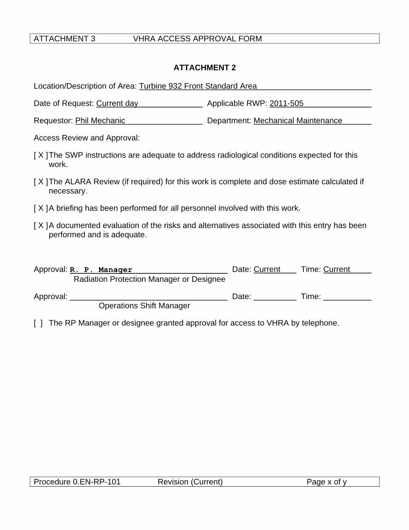
ATTACHMENT 3 VHRA ACCESS APPROVAL FORM
Procedure 0.EN-RP-101 Revision (Current) Page x of y
ATTACHMENT 2
Location/Description of Area: Turbine 932 Front Standard Area
Date of Request: Current day Applicable RWP: 2011-505
Requestor: Phil Mechanic Department: Mechanical Maintenance
Access Review and Approval:
[ X ] The SWP instructions are adequate to address radiological conditions expected for this work.
[ X ] The ALARA Review (if required) for this work is complete and dose estimate calculated if necessary.
[ X ] A briefing has been performed for all personnel involved with this work.
[ X ] A documented evaluation of the risks and alternatives associated with this entry has been performed and is adequate.
Approval: R. P. Manager Date: Current Time: Current Radiation Protection Manager or Designee
Approval: Date: Time: Operations Shift Manager
[ ] The RP Manager or designee granted approval for access to VHRA by telephone.
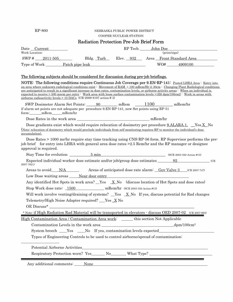
RP-800 NEBRASKA PUBLIC POWER DISTRICT COOPER NUCLEAR STATION
Radiation Protection Pre-Job Brief Form Date __Current__________ RP Tech ______John Doe__________________________ Work Location: (print/sign)
SWP # ____2011-505_______ Bldg. _Turb__ Elev. __932___ Area __Front Standard Area___________ Type of Work _________Patch pipe leak_____________________________ WO# ______4909100___________ The following subjects should be considered for discussion during pre-job briefings. NOTE: The following conditions require Continuous Job Coverage per 9.EN-RP-141: Posted LHRA Area : Entry into an area where unknown radiological conditions exist : Movement of RAM ≥ 100 mRem/Hr @ 30cm : Changing Plant Radiological conditions are anticipated to result in a significant increase in dose rates, contamination levels, or airborne activity areas : When an individual is expected to receive > 500 mrem per entry : Work area with loose surface contamination levels >1E6 dpm/100cm2 : Work in areas with airborne radioactivity levels > 10 DACs (CR-2009-8197 action # 3)
� SWP Dosimeter Alarm Set Points: _____90_________ mRem ____1100________ mRem/hr if alarm set points are not adequate per procedure 9.EN-RP-141, new Set points using RP-51 form:_______mRem______mRem/hr � Dose Rates in the work area ______________________________________ mRem/hr � Dose gradients exist which would require relocation of dosimetry per procedure 9.ALARA.1, __Yes X_ No (Note: relocation of dosimetry which would preclude individuals from self monitoring requires RP to monitor the individual's dose accumulation).
� Dose Rates > 1000 mr/hr require stay time tracking using CNS-RP-56 form. RP Supervisor performs the pre-job brief for entry into LHRA with general area dose rates >2.5 Rem/hr and the RP manager or designee approval is required. � Stay Time for evolution ___________5 min__________________________________ (SCR 2003-350 Action #15)
� Expected individual worker dose estimate and/or job/group dose estimates ________92_________________ (CR 2007-7621)
� Areas to avoid____N/A_______ � Areas of anticipated dose rate alarm: __Gov Valve 3____(CR 2007-747)
� Low Dose waiting areas _____Near door entry___________________________________________ � Any identified Hot Spots in work area? __Yes _X_No (discuss location of Hot Spots and dose rates) � Stop Work dose rate: _1500_______________ mRem/hr (SCR 2003-350 Action #15)
� Will work involve venting/draining of systems? __Yes _X_No If yes, discuss potential for Rad changes � Telemetry/High Noise Adapter required? ___Yes _X No � OE Discuss* ____________________________________________________________________________ * Note: if High Radiation Rad Material will be transported in elevators - discuss OED 2007-02 (CR 2007-693) High Contamination Area / Contamination Area work: ______ this section Not Applicable � Contamination Levels in the work area ______________________________________dpm/100cm2 � System breech ____Yes ____No If yes, contamination levels expected_____________________________ � Types of Engineering Controls to be used to control airborne/spread of contamination: ____________________ � Potential Airborne Activities__________________________________________________________________ � Respiratory Protection worn? Yes_______ No________ What Type? _________________________________
� Any additional comments: _____None____________________________________________________________
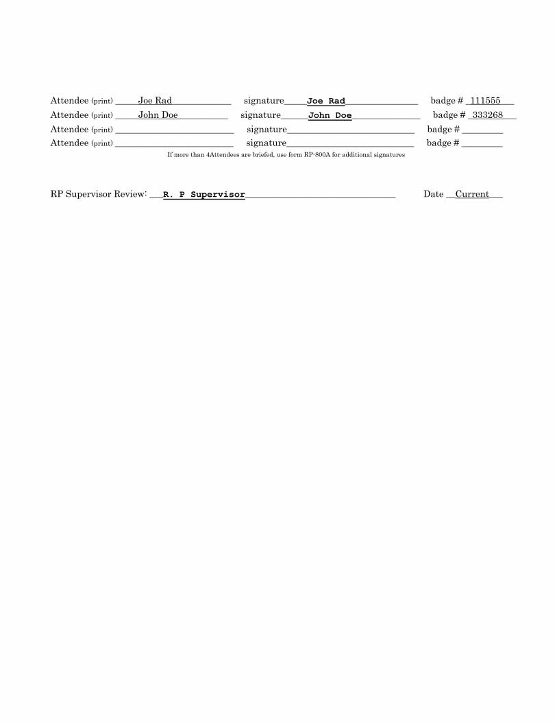
Attendee (print) _____Joe Rad_____________ signature_____Joe Rad________________ badge # _111555___ Attendee (print) _____John Doe___________ signature______John Doe_______________ badge # _333268___ Attendee (print) __________________________ signature____________________________ badge # _________ Attendee (print) __________________________ signature____________________________ badge # _________ If more than 4Attendees are briefed, use form RP-800A for additional signatures
RP Supervisor Review: ___R. P Supervisor_________________________________ Date __Current___
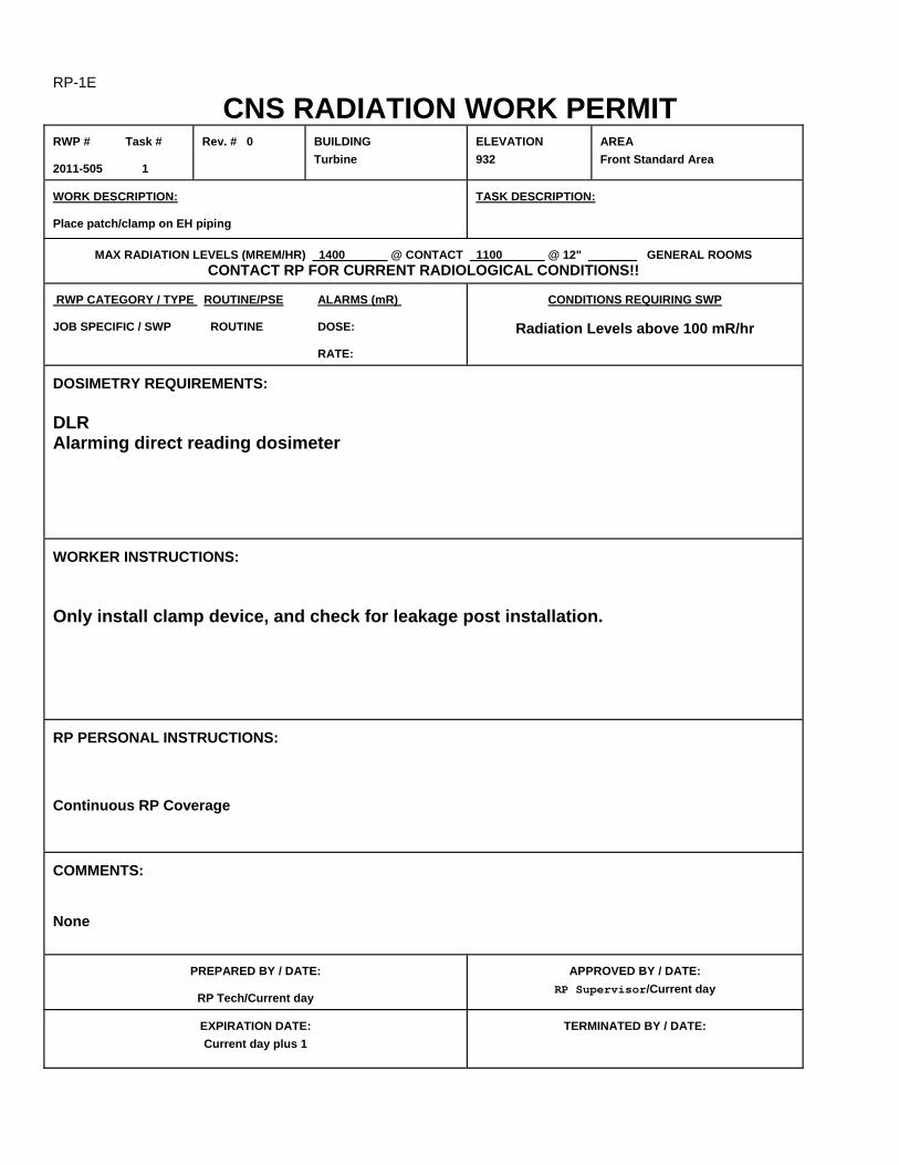
RP-1E CNS RADIATION WORK PERMIT
RWP # Task # 2011-505 1
Rev. # 0
BUILDING Turbine
ELEVATION 932
AREA Front Standard Area
WORK DESCRIPTION: Place patch/clamp on EH piping
TASK DESCRIPTION:
MAX RADIATION LEVELS (MREM/HR) 1400 @ CONTACT 1100 @ 12" GENERAL ROOMS
CONTACT RP FOR CURRENT RADIOLOGICAL CONDITIONS!! RWP CATEGORY / TYPE ROUTINE/PSE ALARMS (mR) JOB SPECIFIC / SWP ROUTINE DOSE:
RATE:
CONDITIONS REQUIRING SWP
Radiation Levels above 100 mR/hr
DOSIMETRY REQUIREMENTS: DLR Alarming direct reading dosimeter WORKER INSTRUCTIONS: Only install clamp device, and check for leakage post installation. RP PERSONAL INSTRUCTIONS: Continuous RP Coverage COMMENTS: None
PREPARED BY / DATE:
RP Tech/Current day
APPROVED BY / DATE: RP Supervisor/Current day
EXPIRATION DATE: Current day plus 1
TERMINATED BY / DATE:
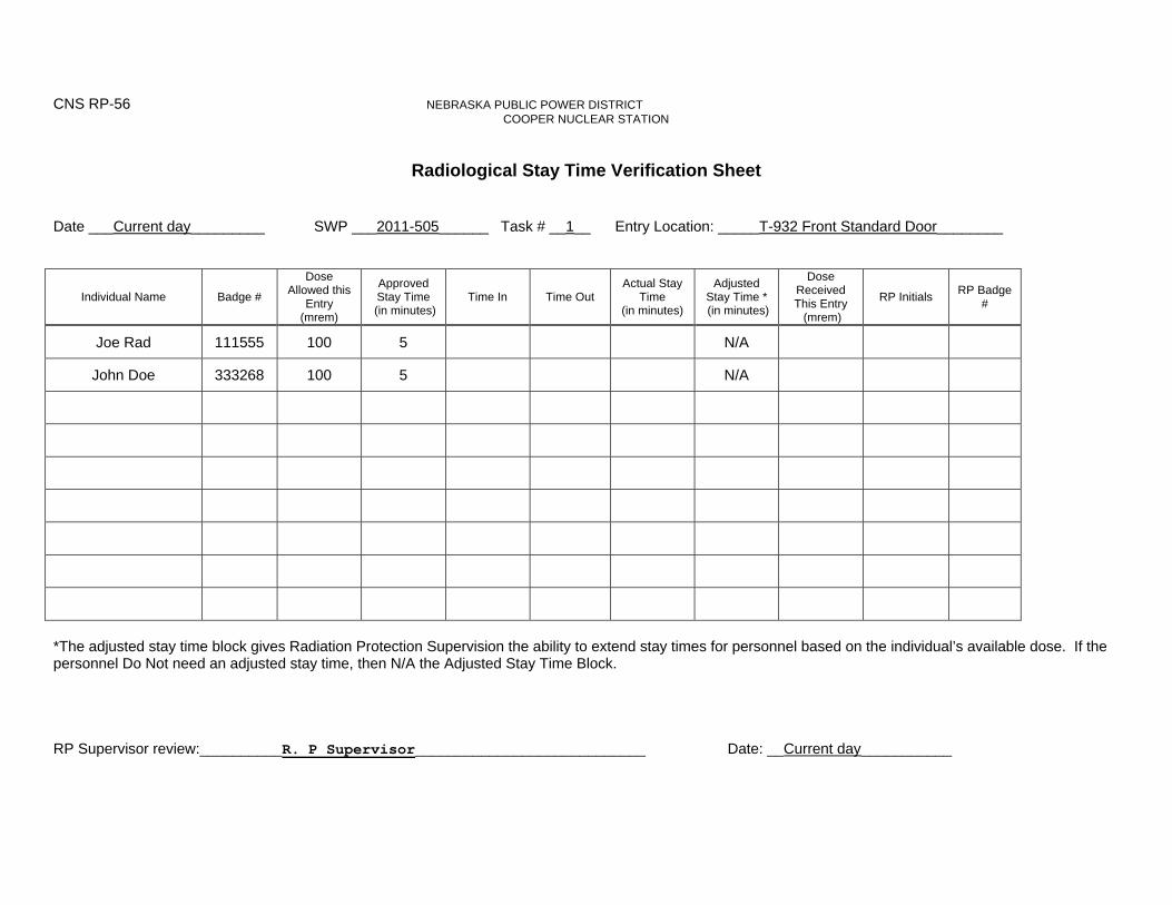
CNS RP-56 NEBRASKA PUBLIC POWER DISTRICT COOPER NUCLEAR STATION
Radiological Stay Time Verification Sheet
Date ___Current day_________ SWP ___2011-505______ Task # __1__ Entry Location: _____T-932 Front Standard Door________
Individual Name Badge #
Dose Allowed this
Entry (mrem)
Approved Stay Time
(in minutes) Time In Time Out
Actual Stay Time
(in minutes)
Adjusted Stay Time * (in minutes)
Dose Received This Entry (mrem)
RP Initials RP Badge #
Joe Rad 111555 100 5 N/A
John Doe 333268 100 5 N/A
*The adjusted stay time block gives Radiation Protection Supervision the ability to extend stay times for personnel based on the individual’s available dose. If the personnel Do Not need an adjusted stay time, then N/A the Adjusted Stay Time Block. RP Supervisor review:__________R. P Supervisor____________________________ Date: __Current day___________
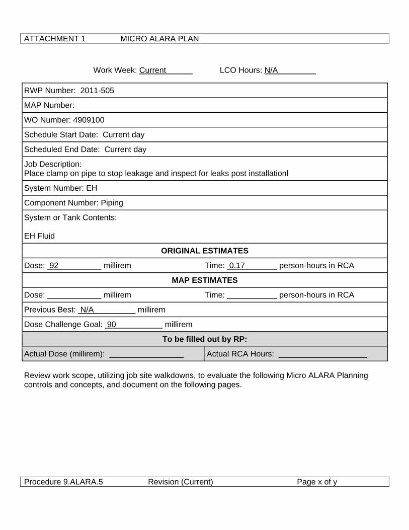
ATTACHMENT 1 MICRO ALARA PLAN
Procedure 9.ALARA.5 Revision (Current) Page x of y
Work Week: Current LCO Hours: N/A
RWP Number: 2011-505
MAP Number:
WO Number: 4909100
Schedule Start Date: Current day
Scheduled End Date: Current day
Job Description: Place clamp on pipe to stop leakage and inspect for leaks post installationl
System Number: EH
Component Number: Piping
System or Tank Contents: EH Fluid
ORIGINAL ESTIMATES
Dose: 92 millirem Time: 0.17 person-hours in RCA
MAP ESTIMATES
Dose: millirem Time: person-hours in RCA
Previous Best: N/A millirem
Dose Challenge Goal: 90 millirem
To be filled out by RP:
Actual Dose (millirem): Actual RCA Hours: Review work scope, utilizing job site walkdowns, to evaluate the following Micro ALARA Planning controls and concepts, and document on the following pages.
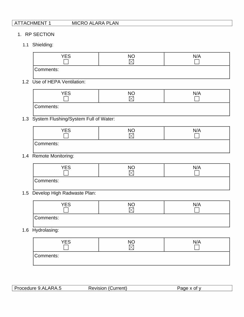
ATTACHMENT 1 MICRO ALARA PLAN
Procedure 9.ALARA.5 Revision (Current) Page x of y
1. RP SECTION
1.1 Shielding:
YES
NO
N/A
Comments:
1.2 Use of HEPA Ventilation:
YES
NO
N/A
Comments:
1.3 System Flushing/System Full of Water:
YES
NO
N/A
Comments:
1.4 Remote Monitoring:
YES
NO
N/A
Comments:
1.5 Develop High Radwaste Plan:
YES
NO
N/A
Comments:
1.6 Hydrolasing:
YES
NO
N/A
Comments:
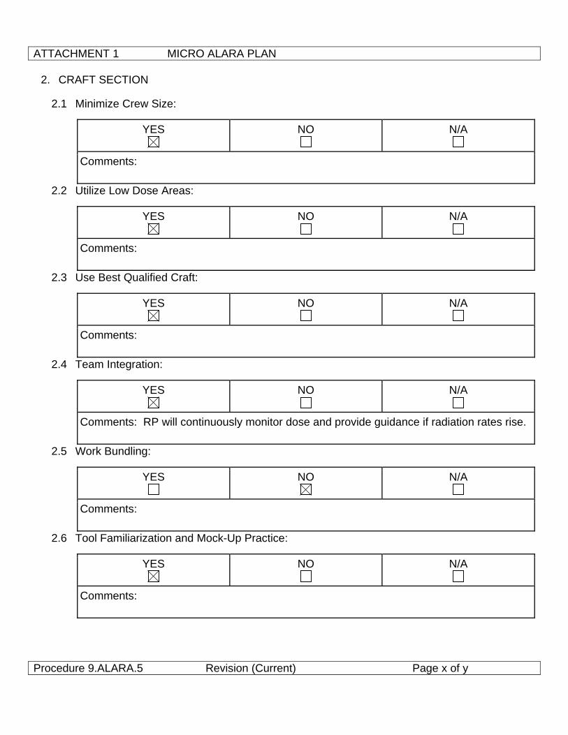
ATTACHMENT 1 MICRO ALARA PLAN
Procedure 9.ALARA.5 Revision (Current) Page x of y
2. CRAFT SECTION
2.1 Minimize Crew Size:
YES
NO
N/A
Comments:
2.2 Utilize Low Dose Areas:
YES
NO
N/A
Comments:
2.3 Use Best Qualified Craft:
YES
NO
N/A
Comments:
2.4 Team Integration:
YES
NO
N/A
Comments: RP will continuously monitor dose and provide guidance if radiation rates rise.
2.5 Work Bundling:
YES
NO
N/A
Comments:
2.6 Tool Familiarization and Mock-Up Practice:
YES
NO
N/A
Comments:
ATTACHMENT 1 MICRO ALARA PLAN
Procedure 9.ALARA.5 Revision (Current) Page x of y
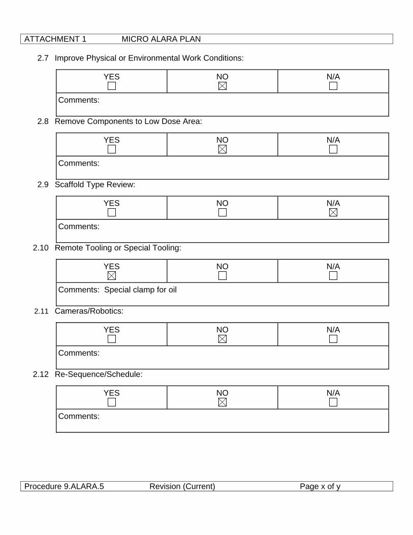
2.7 Improve Physical or Environmental Work Conditions:
YES
NO
N/A
Comments:
2.8 Remove Components to Low Dose Area:
YES
NO
N/A
Comments:
2.9 Scaffold Type Review:
YES
NO
N/A
Comments:
2.10 Remote Tooling or Special Tooling:
YES
NO
N/A
Comments: Special clamp for oil
2.11 Cameras/Robotics:
YES
NO
N/A
Comments:
2.12 Re-Sequence/Schedule:
YES
NO
N/A
Comments:
ATTACHMENT 1 MICRO ALARA PLAN
Procedure 9.ALARA.5 Revision (Current) Page x of y
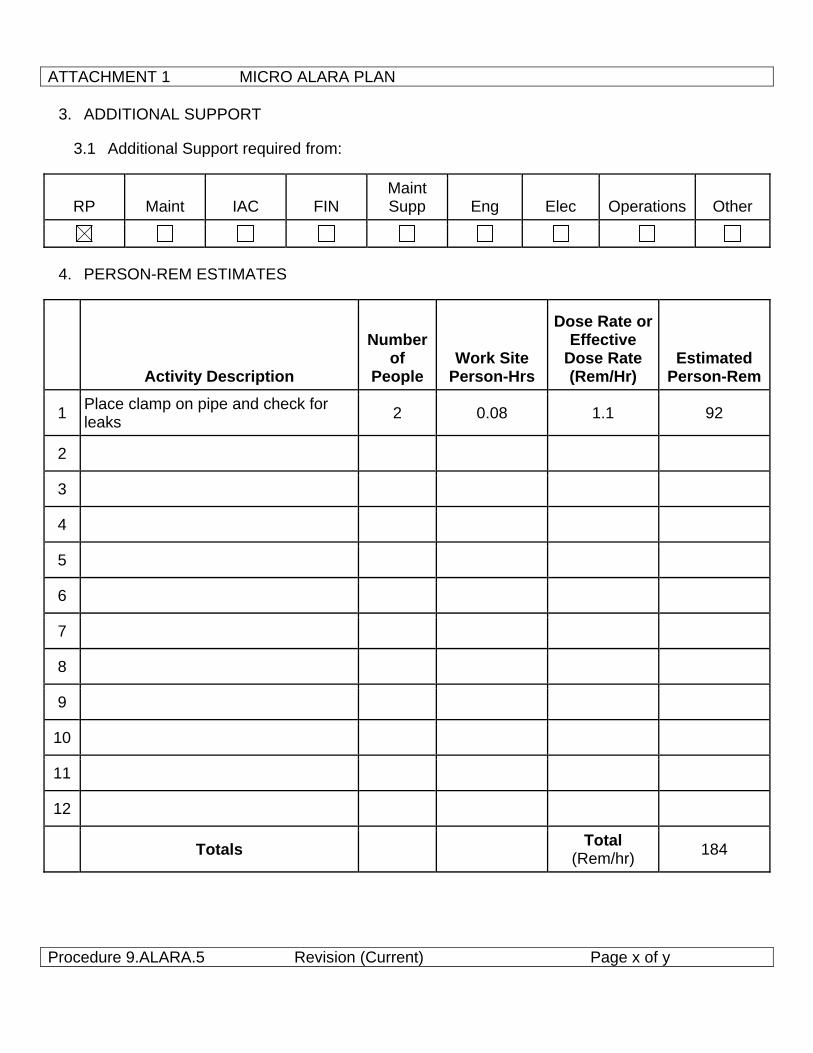
3. ADDITIONAL SUPPORT
3.1 Additional Support required from:
RP Maint IAC FIN Maint Supp Eng Elec Operations Other
4. PERSON-REM ESTIMATES
Activity Description
Number of
People Work Site
Person-Hrs
Dose Rate or Effective
Dose Rate (Rem/Hr)
Estimated Person-Rem
1 Place clamp on pipe and check for leaks 2 0.08 1.1 92
2
3
4
5
6
7
8
9
10
11
12
Totals Total (Rem/hr) 184
ATTACHMENT 1 MICRO ALARA PLAN
Procedure 9.ALARA.5 Revision (Current) Page x of y
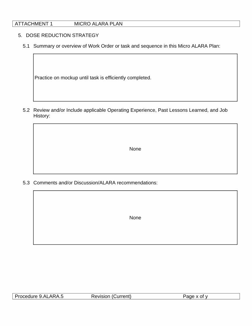
5. DOSE REDUCTION STRATEGY
5.1 Summary or overview of Work Order or task and sequence in this Micro ALARA Plan:
Practice on mockup until task is efficiently completed.
5.2 Review and/or Include applicable Operating Experience, Past Lessons Learned, and Job
History:
None
5.3 Comments and/or Discussion/ALARA recommendations:
None
ATTACHMENT 1 MICRO ALARA PLAN
Procedure 9.ALARA.5 Revision (Current) Page x of y
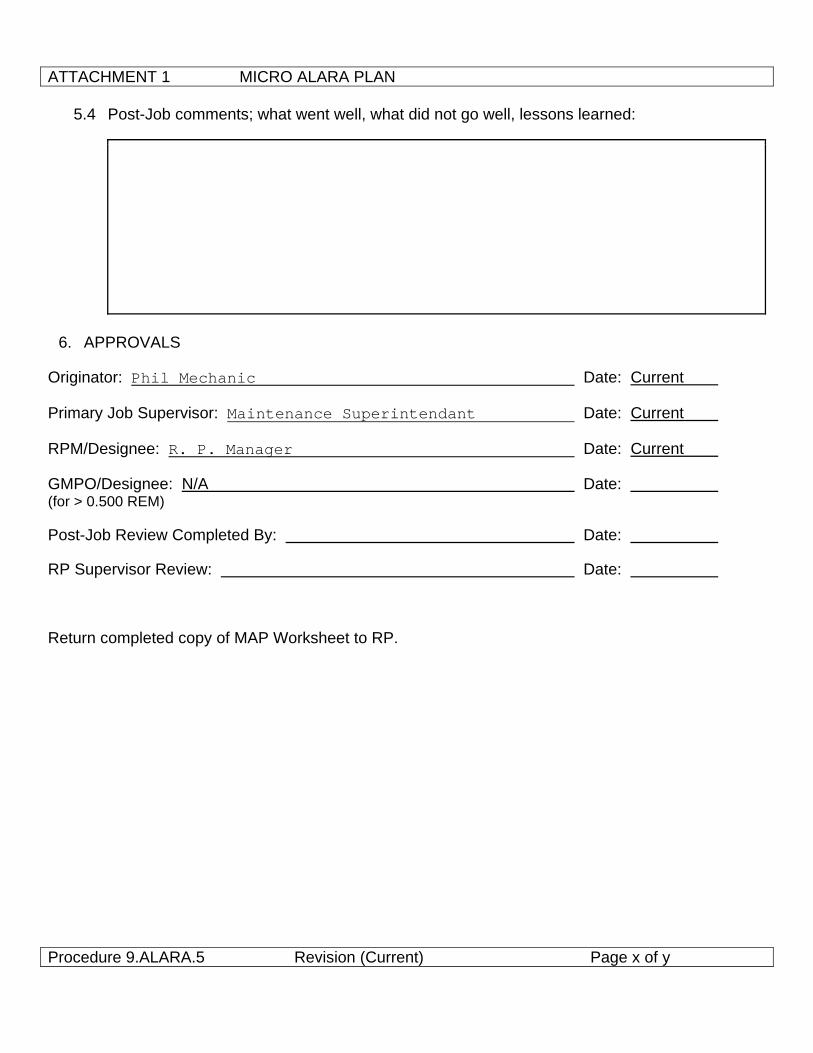
5.4 Post-Job comments; what went well, what did not go well, lessons learned:
6. APPROVALS
Originator: Phil Mechanic Date: Current
Primary Job Supervisor: Maintenance Superintendant Date: Current
RPM/Designee: R. P. Manager Date: Current
GMPO/Designee: N/A Date: (for > 0.500 REM)
Post-Job Review Completed By: Date:
RP Supervisor Review: Date:
Return completed copy of MAP Worksheet to RP.
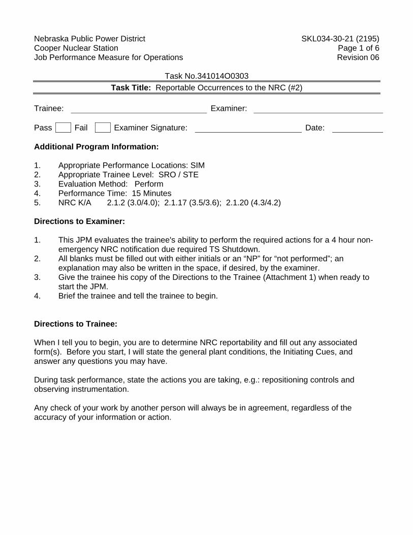
Nebraska Public Power District SKL034-30-21 (2195) Cooper Nuclear Station Page 1 of 6 Job Performance Measure for Operations Revision 06
Task No.341014O0303 Task Title: Reportable Occurrences to the NRC (#2)
Trainee: Examiner: Pass Fail Examiner Signature: Date: Additional Program Information: 1. Appropriate Performance Locations: SIM 2. Appropriate Trainee Level: SRO / STE 3. Evaluation Method: Perform 4. Performance Time: 15 Minutes 5. NRC K/A 2.1.2 (3.0/4.0); 2.1.17 (3.5/3.6); 2.1.20 (4.3/4.2) Directions to Examiner: 1. This JPM evaluates the trainee's ability to perform the required actions for a 4 hour non-
emergency NRC notification due required TS Shutdown. 2. All blanks must be filled out with either initials or an “NP” for “not performed”; an
explanation may also be written in the space, if desired, by the examiner. 3. Give the trainee his copy of the Directions to the Trainee (Attachment 1) when ready to
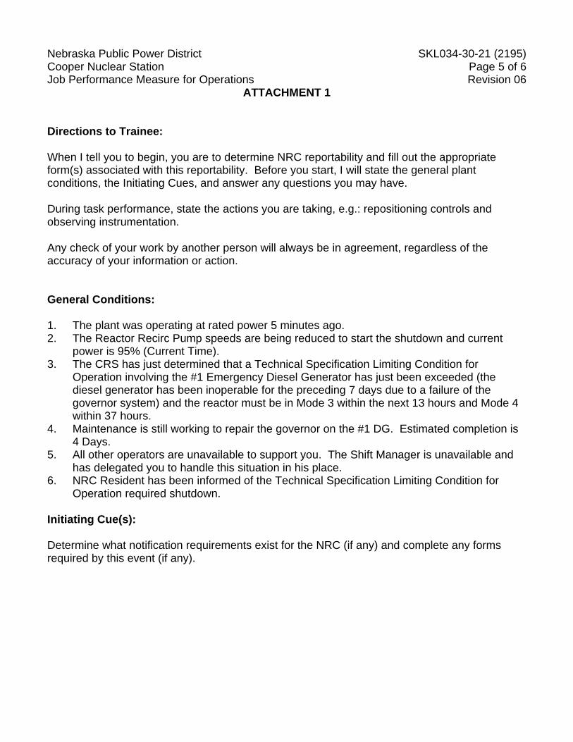
start the JPM. 4. Brief the trainee and tell the trainee to begin. Directions to Trainee: When I tell you to begin, you are to determine NRC reportability and fill out any associated form(s). Before you start, I will state the general plant conditions, the Initiating Cues, and answer any questions you may have. During task performance, state the actions you are taking, e.g.: repositioning controls and observing instrumentation. Any check of your work by another person will always be in agreement, regardless of the accuracy of your information or action.
Nebraska Public Power District SKL034-30-21 (2195) Cooper Nuclear Station Page 2 of 6 Job Performance Measure for Operations Revision 06
Task No.341014O0303 Task Title: Reportable Occurrences to the NRC (#2)
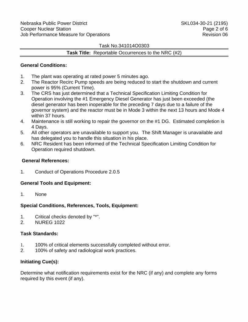
General Conditions: 1. The plant was operating at rated power 5 minutes ago. 2. The Reactor Recirc Pump speeds are being reduced to start the shutdown and current
power is 95% (Current Time). 3. The CRS has just determined that a Technical Specification Limiting Condition for
Operation involving the #1 Emergency Diesel Generator has just been exceeded (the diesel generator has been inoperable for the preceding 7 days due to a failure of the governor system) and the reactor must be in Mode 3 within the next 13 hours and Mode 4 within 37 hours.
4. Maintenance is still working to repair the governor on the #1 DG. Estimated completion is 4 Days.
5. All other operators are unavailable to support you. The Shift Manager is unavailable and has delegated you to handle this situation in his place.
6. NRC Resident has been informed of the Technical Specification Limiting Condition for Operation required shutdown.
General References: 1. Conduct of Operations Procedure 2.0.5 General Tools and Equipment: 1. None Special Conditions, References, Tools, Equipment: 1. Critical checks denoted by "*". 2. NUREG 1022 Task Standards: 1. 100% of critical elements successfully completed without error. 2. 100% of safety and radiological work practices. Initiating Cue(s): Determine what notification requirements exist for the NRC (if any) and complete any forms required by this event (if any).
Nebraska Public Power District SKL034-30-21 (2195) Cooper Nuclear Station Page 3 of 6 Job Performance Measure for Operations Revision 06
Task No.341014O0303 Task Title: Reportable Occurrences to the NRC (#2)
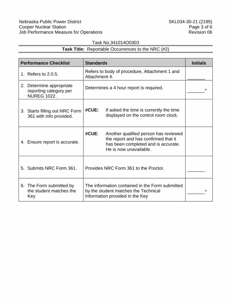
Performance Checklist Standards Initials
1. Refers to 2.0.5. Refers to body of procedure, Attachment 1 and Attachment 4.
_______
2. Determine appropriate reporting category per NUREG 1022.
Determines a 4 hour report is required.
_______*
3. Starts filling out NRC Form 361 with info provided.
#CUE: If asked the time is currently the time displayed on the control room clock.
4. Ensure report is accurate.
#CUE: Another qualified person has reviewed the report and has confirmed that it has been completed and is accurate. He is now unavailable.
5. Submits NRC Form 361. Provides NRC Form 361 to the Proctor.
_______
6. The Form submitted by the student matches the Key
The information contained in the Form submitted by the student matches the Technical Information provided in the Key
_______*
Nebraska Public Power District SKL034-30-21 (2195) Cooper Nuclear Station Page 4 of 6 Job Performance Measure for Operations Revision 06
Task No.341014O0303 Task Title: Reportable Occurrences to the NRC (#2)
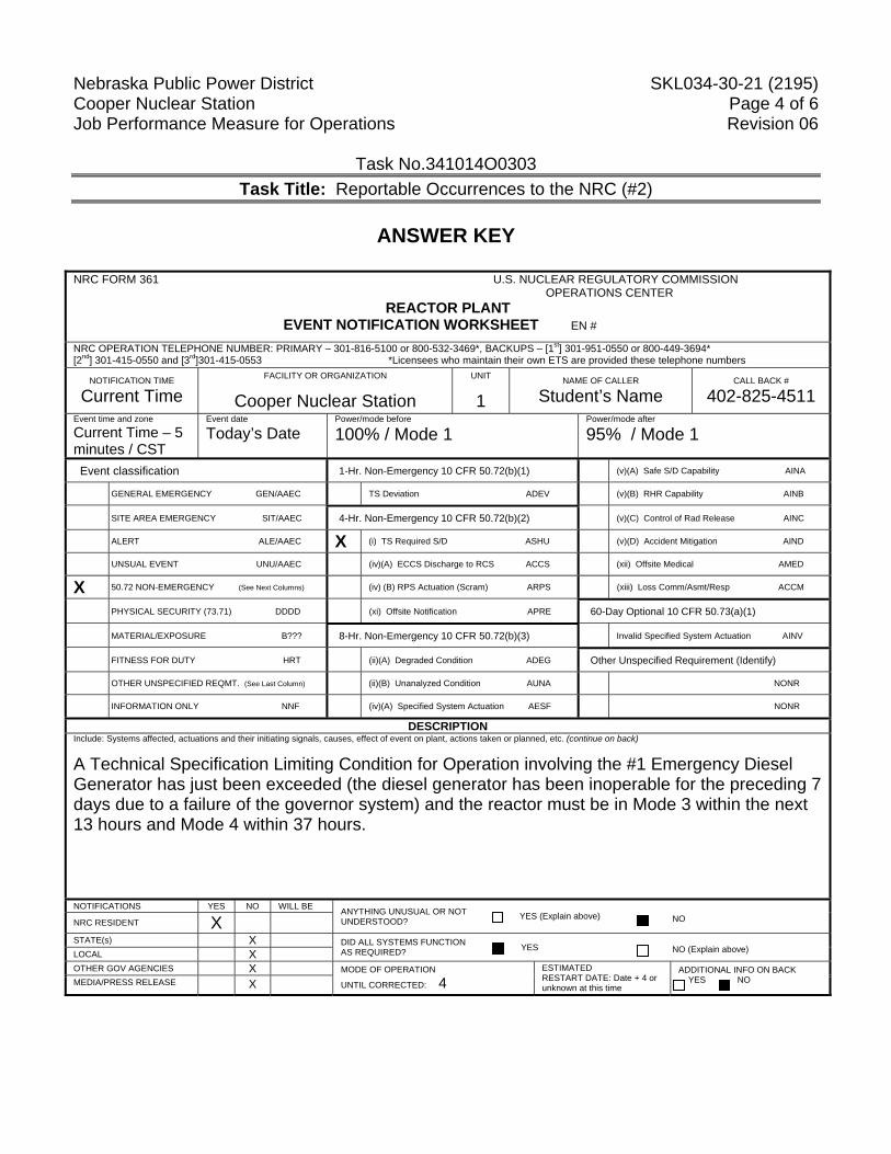
ANSWER KEY
NRC FORM 361 U.S. NUCLEAR REGULATORY COMMISSION OPERATIONS CENTER
REACTOR PLANT EVENT NOTIFICATION WORKSHEET EN #
NRC OPERATION TELEPHONE NUMBER: PRIMARY – 301-816-5100 or 800-532-3469*, BACKUPS – [1st] 301-951-0550 or 800-449-3694* [2nd] 301-415-0550 and [3rd]301-415-0553 *Licensees who maintain their own ETS are provided these telephone numbers
NOTIFICATION TIME
Current Time FACILITY OR ORGANIZATION
Cooper Nuclear Station UNIT
1 NAME OF CALLER
Student’s Name CALL BACK #
402-825-4511 Event time and zone
Current Time – 5 minutes / CST
Event date
Today’s Date Power/mode before
100% / Mode 1 Power/mode after
95% / Mode 1
Event classification 1-Hr. Non-Emergency 10 CFR 50.72(b)(1) (v)(A) Safe S/D Capability AINA
GENERAL EMERGENCY GEN/AAEC TS Deviation ADEV (v)(B) RHR Capability AINB
SITE AREA EMERGENCY SIT/AAEC 4-Hr. Non-Emergency 10 CFR 50.72(b)(2) (v)(C) Control of Rad Release AINC
ALERT ALE/AAEC X (i) TS Required S/D ASHU (v)(D) Accident Mitigation AIND
UNSUAL EVENT UNU/AAEC (iv)(A) ECCS Discharge to RCS ACCS (xii) Offsite Medical AMED
X 50.72 NON-EMERGENCY (See Next Columns) (iv) (B) RPS Actuation (Scram) ARPS (xiii) Loss Comm/Asmt/Resp ACCM
PHYSICAL SECURITY (73.71) DDDD (xi) Offsite Notification APRE 60-Day Optional 10 CFR 50.73(a)(1)
MATERIAL/EXPOSURE B??? 8-Hr. Non-Emergency 10 CFR 50.72(b)(3) Invalid Specified System Actuation AINV
FITNESS FOR DUTY HRT (ii)(A) Degraded Condition ADEG Other Unspecified Requirement (Identify)
OTHER UNSPECIFIED REQMT. (See Last Column) (ii)(B) Unanalyzed Condition AUNA NONR
INFORMATION ONLY NNF (iv)(A) Specified System Actuation AESF NONR
DESCRIPTION Include: Systems affected, actuations and their initiating signals, causes, effect of event on plant, actions taken or planned, etc. (continue on back)
A Technical Specification Limiting Condition for Operation involving the #1 Emergency Diesel Generator has just been exceeded (the diesel generator has been inoperable for the preceding 7 days due to a failure of the governor system) and the reactor must be in Mode 3 within the next 13 hours and Mode 4 within 37 hours.
NOTIFICATIONS YES NO WILL BE ANYTHING UNUSUAL OR NOT UNDERSTOOD? YES (Explain above) NO NRC RESIDENT X
STATE(s) X DID ALL SYSTEMS FUNCTION AS REQUIRED? YES NO (Explain above) LOCAL X
OTHER GOV AGENCIES X MODE OF OPERATION
UNTIL CORRECTED: 4 ESTIMATED RESTART DATE: Date + 4 or unknown at this time
ADDITIONAL INFO ON BACK YES NO MEDIA/PRESS RELEASE X
Nebraska Public Power District SKL034-30-21 (2195) Cooper Nuclear Station Page 5 of 6 Job Performance Measure for Operations Revision 06
ATTACHMENT 1 Directions to Trainee: When I tell you to begin, you are to determine NRC reportability and fill out the appropriate form(s) associated with this reportability. Before you start, I will state the general plant conditions, the Initiating Cues, and answer any questions you may have. During task performance, state the actions you are taking, e.g.: repositioning controls and observing instrumentation. Any check of your work by another person will always be in agreement, regardless of the accuracy of your information or action. General Conditions: 1. The plant was operating at rated power 5 minutes ago. 2. The Reactor Recirc Pump speeds are being reduced to start the shutdown and current
power is 95% (Current Time). 3. The CRS has just determined that a Technical Specification Limiting Condition for
Operation involving the #1 Emergency Diesel Generator has just been exceeded (the diesel generator has been inoperable for the preceding 7 days due to a failure of the governor system) and the reactor must be in Mode 3 within the next 13 hours and Mode 4 within 37 hours.
4. Maintenance is still working to repair the governor on the #1 DG. Estimated completion is 4 Days.
5. All other operators are unavailable to support you. The Shift Manager is unavailable and has delegated you to handle this situation in his place.
6. NRC Resident has been informed of the Technical Specification Limiting Condition for Operation required shutdown.
Initiating Cue(s): Determine what notification requirements exist for the NRC (if any) and complete any forms required by this event (if any).
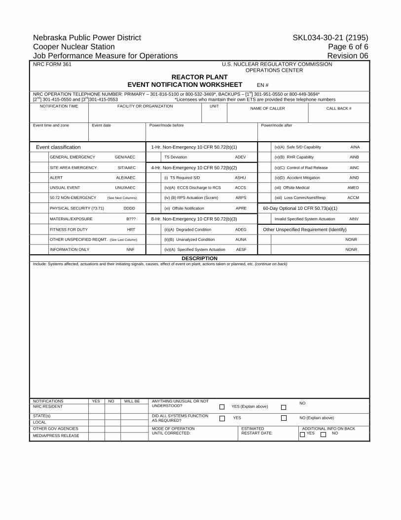
Nebraska Public Power District SKL034-30-21 (2195) Cooper Nuclear Station Page 6 of 6 Job Performance Measure for Operations Revision 06 NRC FORM 361 U.S. NUCLEAR REGULATORY COMMISSION OPERATIONS CENTER
REACTOR PLANT EVENT NOTIFICATION WORKSHEET EN #
NRC OPERATION TELEPHONE NUMBER: PRIMARY – 301-816-5100 or 800-532-3469*, BACKUPS – [1st] 301-951-0550 or 800-449-3694* [2nd] 301-415-0550 and [3rd]301-415-0553 *Licensees who maintain their own ETS are provided these telephone numbers
NOTIFICATION TIME
FACILITY OR ORGANIZATION
UNIT
NAME OF CALLER
CALL BACK #
Event time and zone
Event date
Power/mode before
Power/mode after
Event classification 1-Hr. Non-Emergency 10 CFR 50.72(b)(1) (v)(A) Safe S/D Capability AINA
GENERAL EMERGENCY GEN/AAEC TS Deviation ADEV (v)(B) RHR Capability AINB
SITE AREA EMERGENCY SIT/AAEC 4-Hr. Non-Emergency 10 CFR 50.72(b)(2) (v)(C) Control of Rad Release AINC
ALERT ALE/AAEC (i) TS Required S/D ASHU (v)(D) Accident Mitigation AIND
UNSUAL EVENT UNU/AAEC (iv)(A) ECCS Discharge to RCS ACCS (xii) Offsite Medical AMED
50.72 NON-EMERGENCY (See Next Columns) (iv) (B) RPS Actuation (Scram) ARPS (xiii) Loss Comm/Asmt/Resp ACCM
PHYSICAL SECURITY (73.71) DDDD (xi) Offsite Notification APRE 60-Day Optional 10 CFR 50.73(a)(1)
MATERIAL/EXPOSURE B??? 8-Hr. Non-Emergency 10 CFR 50.72(b)(3) Invalid Specified System Actuation AINV
FITNESS FOR DUTY HRT (ii)(A) Degraded Condition ADEG Other Unspecified Requirement (Identify)
OTHER UNSPECIFIED REQMT. (See Last Column) (ii)(B) Unanalyzed Condition AUNA NONR
INFORMATION ONLY NNF (iv)(A) Specified System Actuation AESF NONR
DESCRIPTION Include: Systems affected, actuations and their initiating signals, causes, effect of event on plant, actions taken or planned, etc. (continue on back)
NOTIFICATIONS YES NO WILL BE ANYTHING UNUSUAL OR NOT UNDERSTOOD? YES (Explain above)
NO NRC RESIDENT
STATE(s) DID ALL SYSTEMS FUNCTION AS REQUIRED? YES NO (Explain above)
LOCAL OTHER GOV AGENCIES MODE OF OPERATION
UNTIL CORRECTED: ESTIMATED RESTART DATE:
ADDITIONAL INFO ON BACK YES NO MEDIA/PRESS RELEASE
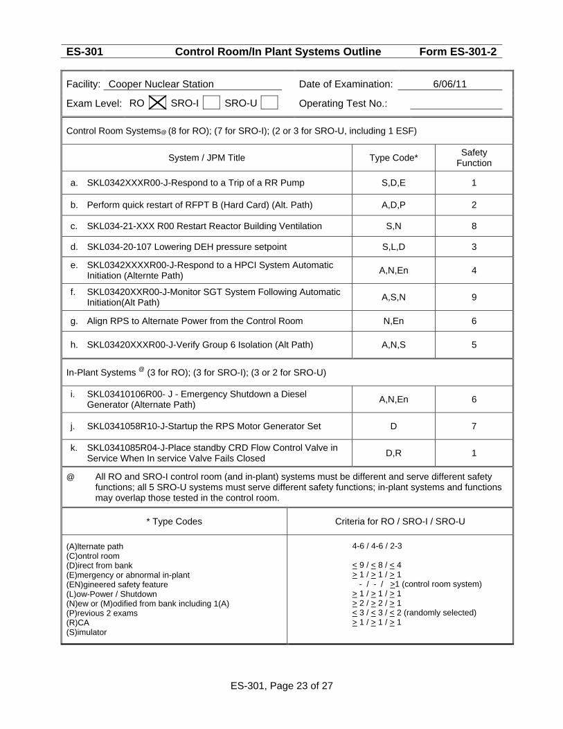
ES-301 Control Room/In Plant Systems Outline Form ES-301-2
Facility: Cooper Nuclear Station Date of Examination: 6/06/11
Exam Level:
Operating Test No.:
RO SRO-I SRO-U
Control Room Systems@ (8 for RO); (7 for SRO-I); (2 or 3 for SRO-U, including 1 ESF)
System / JPM Title Type Code* Safety Function
a. SKL0342XXXR00-J-Respond to a Trip of a RR Pump S,D,E 1
b. Perform quick restart of RFPT B (Hard Card) (Alt. Path) A,D,P 2
c. SKL034-21-XXX R00 Restart Reactor Building Ventilation S,N 8
d. SKL034-20-107 Lowering DEH pressure setpoint S,L,D 3
e. SKL0342XXXXR00-J-Respond to a HPCI System Automatic Initiation (Alternte Path) A,N,En 4
f. SKL03420XXR00-J-Monitor SGT System Following Automatic Initiation(Alt Path) A,S,N 9
g. Align RPS to Alternate Power from the Control Room N,En 6
h. SKL03420XXXR00-J-Verify Group 6 Isolation (Alt Path) A,N,S 5
In-Plant Systems @ (3 for RO); (3 for SRO-I); (3 or 2 for SRO-U)
i. SKL03410106R00- J - Emergency Shutdown a Diesel Generator (Alternate Path) A,N,En 6
j. SKL0341058R10-J-Startup the RPS Motor Generator Set D 7
k. SKL0341085R04-J-Place standby CRD Flow Control Valve in Service When In service Valve Fails Closed D,R 1
@ All RO and SRO-I control room (and in-plant) systems must be different and serve different safety functions; all 5 SRO-U systems must serve different safety functions; in-plant systems and functions may overlap those tested in the control room.
* Type Codes Criteria for RO / SRO-I / SRO-U
(A)lternate path (C)ontrol room (D)irect from bank (E)mergency or abnormal in-plant (EN)gineered safety feature (L)ow-Power / Shutdown (N)ew or (M)odified from bank including 1(A) (P)revious 2 exams (R)CA (S)imulator
4-6 / 4-6 / 2-3 < 9 / < 8 / < 4 > 1 / > 1 / > 1 - / - / >1 (control room system) > 1 / > 1 / > 1 > 2 / > 2 / > 1 < 3 / < 3 / < 2 (randomly selected) > 1 / > 1 / > 1
ES-301, Page 23 of 27
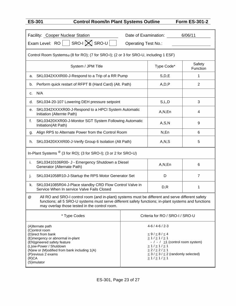
ES-301 Control Room/In Plant Systems Outline Form ES-301-2
Facility: Cooper Nuclear Station Date of Examination: 6/06/11
Exam Level:
Operating Test No.:
RO SRO-I SRO-U
Control Room Systems@ (8 for RO); (7 for SRO-I); (2 or 3 for SRO-U, including 1 ESF)
System / JPM Title Type Code* Safety Function
a. SKL0342XXXR00-J-Respond to a Trip of a RR Pump S,D,E 1
b. Perform quick restart of RFPT B (Hard Card) (Alt. Path) A,D,P 2
c. N/A
d. SKL034-20-107 Lowering DEH pressure setpoint S,L,D 3
e. SKL0342XXXXR00-J-Respond to a HPCI System Automatic Initiation (Alternte Path) A,N,En 4
f. SKL03420XXR00-J-Monitor SGT System Following Automatic Initiation(Alt Path) A,S,N 9
g. Align RPS to Alternate Power from the Control Room N,En 6
h. SKL03420XXXR00-J-Verify Group 6 Isolation (Alt Path) A,N,S 5
In-Plant Systems @ (3 for RO); (3 for SRO-I); (3 or 2 for SRO-U)
i. SKL03410106R00- J - Emergency Shutdown a Diesel Generator (Alternate Path) A,N,En 6
j. SKL0341058R10-J-Startup the RPS Motor Generator Set D 7
k. SKL0341085R04-J-Place standby CRD Flow Control Valve in Service When In service Valve Fails Closed D,R 1
@ All RO and SRO-I control room (and in-plant) systems must be different and serve different safety functions; all 5 SRO-U systems must serve different safety functions; in-plant systems and functions may overlap those tested in the control room.
* Type Codes Criteria for RO / SRO-I / SRO-U
(A)lternate path (C)ontrol room (D)irect from bank (E)mergency or abnormal in-plant (EN)gineered safety feature (L)ow-Power / Shutdown (N)ew or (M)odified from bank including 1(A) (P)revious 2 exams (R)CA (S)imulator
4-6 / 4-6 / 2-3 < 9 / < 8 / < 4 > 1 / > 1 / > 1 - / - / >1 (control room system) > 1 / > 1 / > 1 > 2 / > 2 / > 1 < 3 / < 3 / < 2 (randomly selected) > 1 / > 1 / > 1
ES-301, Page 23 of 27
Nebraska Public Power District SKL034-21-56 (8779) Cooper Nuclear Station Revision 03 Job Performance Measure for Operations Page 1 of 10 Task No.:202022C0401
Task Title: Respond to a Trip of a Reactor Recirc Pump (Alternate Path)
Trainee: Examiner: Pass Fail Examiner Signature: Date: Additional Program Information: NOTE − THIS IS AN ALTERNATE PATH JPM. 1. Appropriate Performance Locations: CR/SIM 2. Appropriate Trainee Level: RO/SRO 3. Evaluation Method: Perform _ Simulate ___ 4. Performance Time: 15 minutes 5. NRC K/As 202001 A2.03 (3.6/3.7) Directions to Examiner: NOTE − THIS IS AN ALTERNATE PATH JPM. The flow subtracting network will fail and require manual input of total core flow.
1. This JPM evaluates the trainee’s ability to respond to a Reactor Recirculation pump trip per
2.4RR, “Reactor Recirculation Abnormal.” 2. If this JPM is performed on the Simulator, only the cues preceded by “#” should be given. 3. All blanks must be filled out with either initials or an “NP” for “not performed”; an
explanation may also be written in the space, if desired, by the examiner. 4. Give the trainee his copy of the Directions to the Trainee (Attachment 2) when ready to
start the JPM. 5. Brief the trainee, place the Simulator in RUN, and tell the trainee to begin. Directions to Trainee: When I tell you to begin, you are to perform actions as appropriate to panel 9-4 and 9-5 indications. Before you start, I will state the general plant conditions, the Initiating Cues, and answer any questions you may have.
Nebraska Public Power District SKL034-21-56 (8779) Cooper Nuclear Station Revision 03 Job Performance Measure for Operations Page 2 of 10 Task No.:202022C0401
Task Title: Respond to a Trip of a Reactor Recirc Pump (Alternate Path)
If being simulated In-Plant or Control Room:
When simulating, physically point to any meters, gauges, recorders and controls you would be using. State the position of controls as you would have manipulated them in order to complete the assigned task.
If being performed in the Simulator:
During task performance, state the actions you are taking, e.g.: repositioning controls and observing instrumentation.
General Conditions: 1. The plant is operating at power. 2. You are the Control Room Operator. General References: 1. Procedure 2.4RR, Reactor Recirculation Abnormal 2. Procedure 2.2.68.1, Reactor Recirculation System Operations General Tools and Equipment: 1. None Special Conditions, References, Tools, Equipment: 1. Simulator Setup: See Attachment 1. 2. Critical steps denoted by “*”. 3. Simulator cues denoted by “#”. Task Standards: 1. 100% of critical elements successfully completed without error. 2. 100% of safety and radiological work practices. Initiating Cue(s): The Control Room Supervisor directs you to perform actions as appropriate to panel 9-4 and panel 9-5 indications.
Nebraska Public Power District SKL034-21-56 (8779) Cooper Nuclear Station Revision 03 Job Performance Measure for Operations Page 3 of 10 Task No.:202022C0401
Task Title: Respond to a Trip of a Reactor Recirc Pump (Alternate Path)
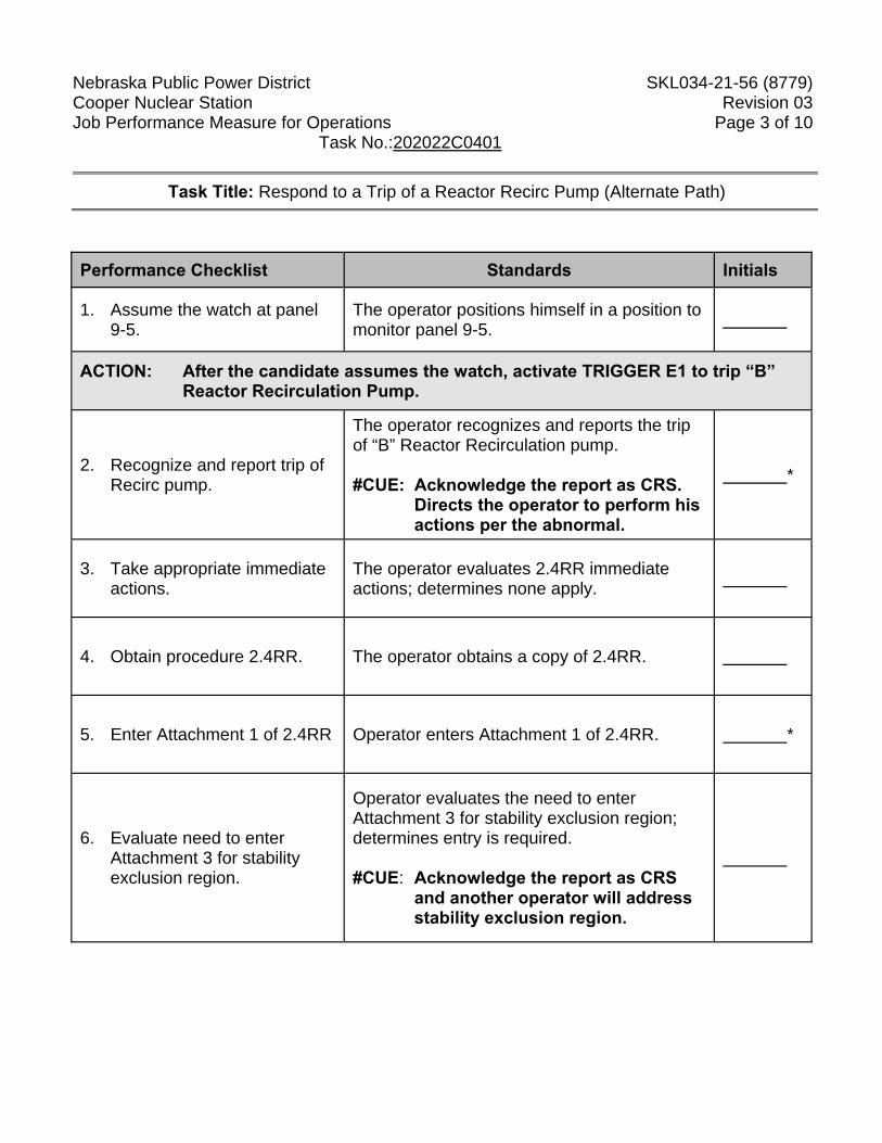
Performance Checklist Standards Initials
1. Assume the watch at panel 9-5.
The operator positions himself in a position to monitor panel 9-5.
ACTION: After the candidate assumes the watch, activate TRIGGER E1 to trip “B” Reactor Recirculation Pump.
2. Recognize and report trip of Recirc pump.
The operator recognizes and reports the trip of “B” Reactor Recirculation pump. #CUE: Acknowledge the report as CRS.
Directs the operator to perform his actions per the abnormal.
*
3. Take appropriate immediate actions.
The operator evaluates 2.4RR immediate actions; determines none apply.
4. Obtain procedure 2.4RR. The operator obtains a copy of 2.4RR.
5. Enter Attachment 1 of 2.4RR Operator enters Attachment 1 of 2.4RR. *
6. Evaluate need to enter Attachment 3 for stability exclusion region.
Operator evaluates the need to enter Attachment 3 for stability exclusion region; determines entry is required. #CUE: Acknowledge the report as CRS
and another operator will address stability exclusion region.
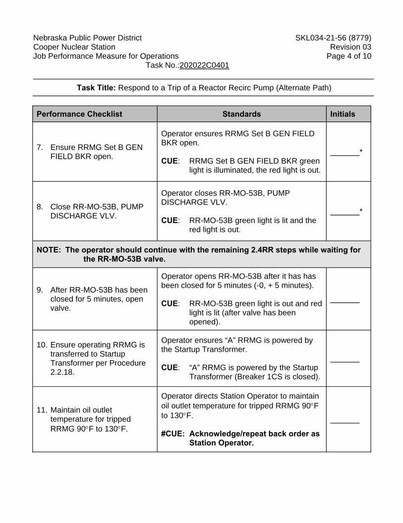
Nebraska Public Power District SKL034-21-56 (8779) Cooper Nuclear Station Revision 03 Job Performance Measure for Operations Page 4 of 10 Task No.:202022C0401
Task Title: Respond to a Trip of a Reactor Recirc Pump (Alternate Path)
Performance Checklist Standards Initials
7. Ensure RRMG Set B GEN FIELD BKR open.
Operator ensures RRMG Set B GEN FIELD BKR open. CUE: RRMG Set B GEN FIELD BKR green
light is illuminated, the red light is out.
*
8. Close RR-MO-53B, PUMP DISCHARGE VLV.
Operator closes RR-MO-53B, PUMP DISCHARGE VLV. CUE: RR-MO-53B green light is lit and the
red light is out.
*
NOTE: The operator should continue with the remaining 2.4RR steps while waiting for the RR-MO-53B valve.
9. After RR-MO-53B has been closed for 5 minutes, open valve.
Operator opens RR-MO-53B after it has has been closed for 5 minutes (-0, + 5 minutes). CUE: RR-MO-53B green light is out and red
light is lit (after valve has been opened).
10. Ensure operating RRMG is transferred to Startup Transformer per Procedure 2.2.18.
Operator ensures “A” RRMG is powered by the Startup Transformer. CUE: “A” RRMG is powered by the Startup
Transformer (Breaker 1CS is closed).
11. Maintain oil outlet temperature for tripped RRMG 90°F to 130°F.
Operator directs Station Operator to maintain oil outlet temperature for tripped RRMG 90°F to 130°F. #CUE: Acknowledge/repeat back order as
Station Operator.
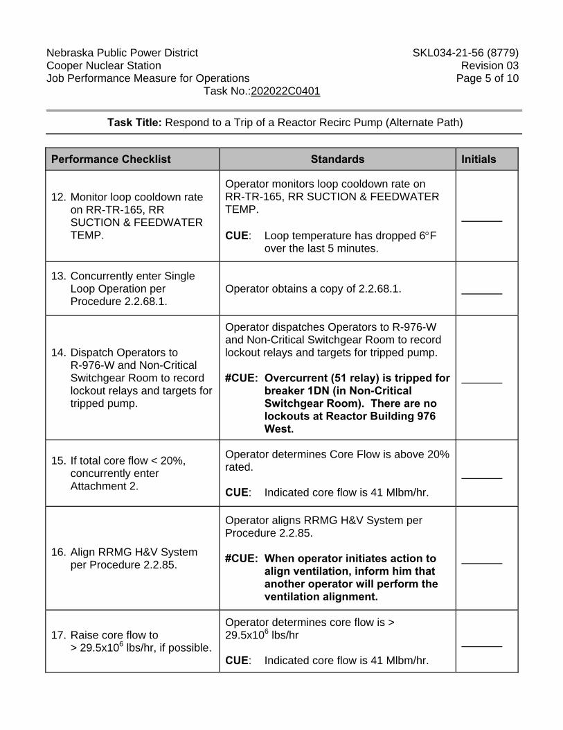
Nebraska Public Power District SKL034-21-56 (8779) Cooper Nuclear Station Revision 03 Job Performance Measure for Operations Page 5 of 10 Task No.:202022C0401
Task Title: Respond to a Trip of a Reactor Recirc Pump (Alternate Path)
Performance Checklist Standards Initials
12. Monitor loop cooldown rate on RR-TR-165, RR SUCTION & FEEDWATER TEMP.
Operator monitors loop cooldown rate on RR-TR-165, RR SUCTION & FEEDWATER TEMP. CUE: Loop temperature has dropped 6°F
over the last 5 minutes.
13. Concurrently enter Single Loop Operation per Procedure 2.2.68.1.
Operator obtains a copy of 2.2.68.1.
14. Dispatch Operators to R-976-W and Non-Critical Switchgear Room to record lockout relays and targets for tripped pump.
Operator dispatches Operators to R-976-W and Non-Critical Switchgear Room to record lockout relays and targets for tripped pump. #CUE: Overcurrent (51 relay) is tripped for
breaker 1DN (in Non-Critical Switchgear Room). There are no lockouts at Reactor Building 976 West.
15. If total core flow < 20%, concurrently enter Attachment 2.
Operator determines Core Flow is above 20% rated. CUE: Indicated core flow is 41 Mlbm/hr.
16. Align RRMG H&V System per Procedure 2.2.85.
Operator aligns RRMG H&V System per Procedure 2.2.85. #CUE: When operator initiates action to
align ventilation, inform him that another operator will perform the ventilation alignment.
17. Raise core flow to > 29.5x10⁶ lbs/hr, if possible.
Operator determines core flow is > 29.5x10⁶ lbs/hr CUE: Indicated core flow is 41 Mlbm/hr.
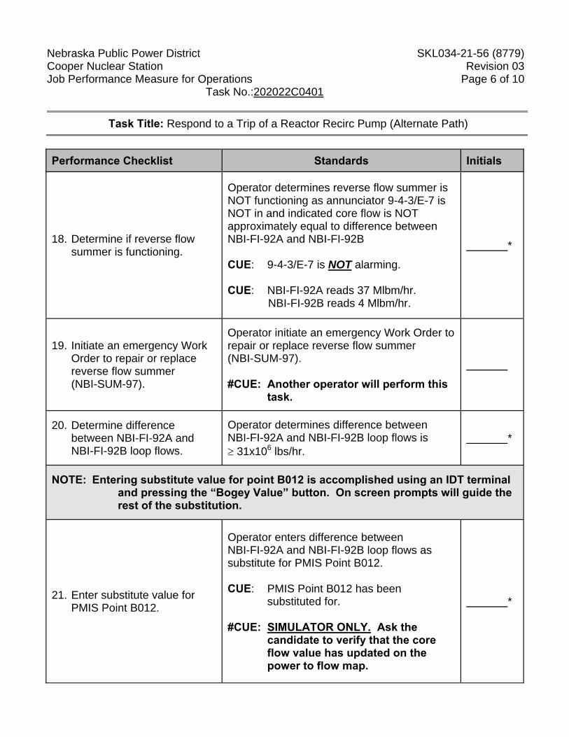
Nebraska Public Power District SKL034-21-56 (8779) Cooper Nuclear Station Revision 03 Job Performance Measure for Operations Page 6 of 10 Task No.:202022C0401
Task Title: Respond to a Trip of a Reactor Recirc Pump (Alternate Path)
Performance Checklist Standards Initials
18. Determine if reverse flow summer is functioning.
Operator determines reverse flow summer is NOT functioning as annunciator 9-4-3/E-7 is NOT in and indicated core flow is NOT approximately equal to difference between NBI-FI-92A and NBI-FI-92B CUE: 9-4-3/E-7 is NOT alarming. CUE: NBI-FI-92A reads 37 Mlbm/hr.
NBI-FI-92B reads 4 Mlbm/hr.
*
19. Initiate an emergency Work Order to repair or replace reverse flow summer (NBI-SUM-97).
Operator initiate an emergency Work Order to repair or replace reverse flow summer (NBI-SUM-97). #CUE: Another operator will perform this
task.
20. Determine difference between NBI-FI-92A and NBI-FI-92B loop flows.
Operator determines difference between NBI-FI-92A and NBI-FI-92B loop flows is ≥ 31x106 lbs/hr.
*
NOTE: Entering substitute value for point B012 is accomplished using an IDT terminal and pressing the “Bogey Value” button. On screen prompts will guide the rest of the substitution.
21. Enter substitute value for PMIS Point B012.
Operator enters difference between NBI-FI-92A and NBI-FI-92B loop flows as substitute for PMIS Point B012. CUE: PMIS Point B012 has been
substituted for. #CUE: SIMULATOR ONLY. Ask the
candidate to verify that the core flow value has updated on the power to flow map.
*
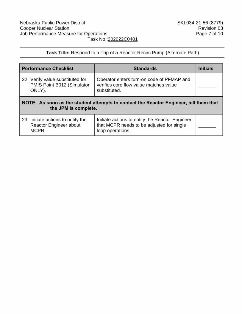
Nebraska Public Power District SKL034-21-56 (8779) Cooper Nuclear Station Revision 03 Job Performance Measure for Operations Page 7 of 10 Task No.:202022C0401
Task Title: Respond to a Trip of a Reactor Recirc Pump (Alternate Path)
Performance Checklist Standards Initials
22. Verify value substituted for PMIS Point B012 (Simulator ONLY).
Operator enters turn-on code of PFMAP and verifies core flow value matches value substituted.
NOTE: As soon as the student attempts to contact the Reactor Engineer, tell them that the JPM is complete.
23. Initiate actions to notify the Reactor Engineer about MCPR.
Initiate actions to notify the Reactor Engineer that MCPR needs to be adjusted for single loop operations
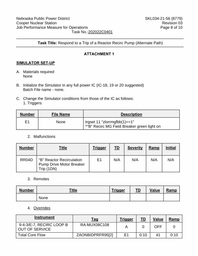
Nebraska Public Power District SKL034-21-56 (8779) Cooper Nuclear Station Revision 03 Job Performance Measure for Operations Page 8 of 10 Task No.:202022C0401
Task Title: Respond to a Trip of a Reactor Recirc Pump (Alternate Path)
ATTACHMENT 1
SIMULATOR SET-UP A. Materials required
None B. Initialize the Simulator in any full power IC (IC-18, 19 or 20 suggested)
Batch File name - none. C. Change the Simulator conditions from those of the IC as follows:
1. Triggers Number
File Name Description
E1
None trgset 11 "zlorrmgfbb(1)==1"
^“B” Recirc MG Field Breaker green light on
2. Malfunctions Number
Title Trigger TD Severity
Ramp Initial
RR04D
“B” Reactor Recirculation Pump Drive Motor Breaker Trip (1DN)
E1 N/A N/A
N/A N/A
3. Remotes
Number
Title Trigger TD
Value Ramp
None
4. Overrides
Instrument
Tag Trigger TD Value Ramp
9-4-3/E-7, RECIRC LOOP B OUT OF SERVICE
RA:MUX08C108 A 0
OFF 0
Total Core Flow ZAONBIDPRFR95[2] E1 0:10 41 0:10
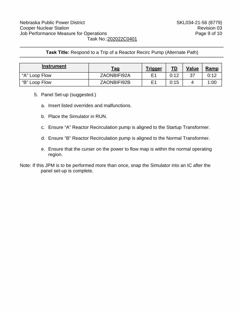
Nebraska Public Power District SKL034-21-56 (8779) Cooper Nuclear Station Revision 03 Job Performance Measure for Operations Page 9 of 10 Task No.:202022C0401
Task Title: Respond to a Trip of a Reactor Recirc Pump (Alternate Path)
Instrument
Tag Trigger TD Value Ramp
“A” Loop Flow ZAONBIFI92A E1 0:12 37 0:12 “B” Loop Flow ZAONBIFI92B E1 0:15 4 1:00
5. Panel Set-up (suggested.)
a. Insert listed overrides and malfunctions. b. Place the Simulator in RUN. c. Ensure “A” Reactor Recirculation pump is aligned to the Startup Transformer. d. Ensure “B” Reactor Recirculation pump is aligned to the Normal Transformer. e. Ensure that the curser on the power to flow map is within the normal operating
region.
Note: If this JPM is to be performed more than once, snap the Simulator into an IC after the panel set-up is complete.
Nebraska Public Power District SKL034-21-56 (8779) Cooper Nuclear Station Revision 03 Job Performance Measure for Operations Page 10 of 10 Task No.:202022C0401
ATTACHMENT 2
Directions to Trainee: When I tell you to begin, you are to perform actions as appropriate to panel 9-4 and 9-5 indications. Before you start, I will state the general plant conditions, the Initiating Cues, and answer any questions you may have. If being simulated In-Plant or Control Room:
When simulating, physically point to any meters, gauges, recorders and controls you would be using. State the position of controls as you would have manipulated them in order to complete the assigned task.
If being performed in the Simulator:
During task performance, state the actions you are taking, e.g.: repositioning controls and observing instrumentation.
General Conditions: 1. The plant is operating at power. 2. You are the CRO - Reactor Operator (RO) (9-5 PNL). 3. Optimum Water Chemistry is out of service. Initiating Cue(s): The Control Room Supervisor directs you to perform actions as appropriate to panel 9-4 and panel 9-5 indications.
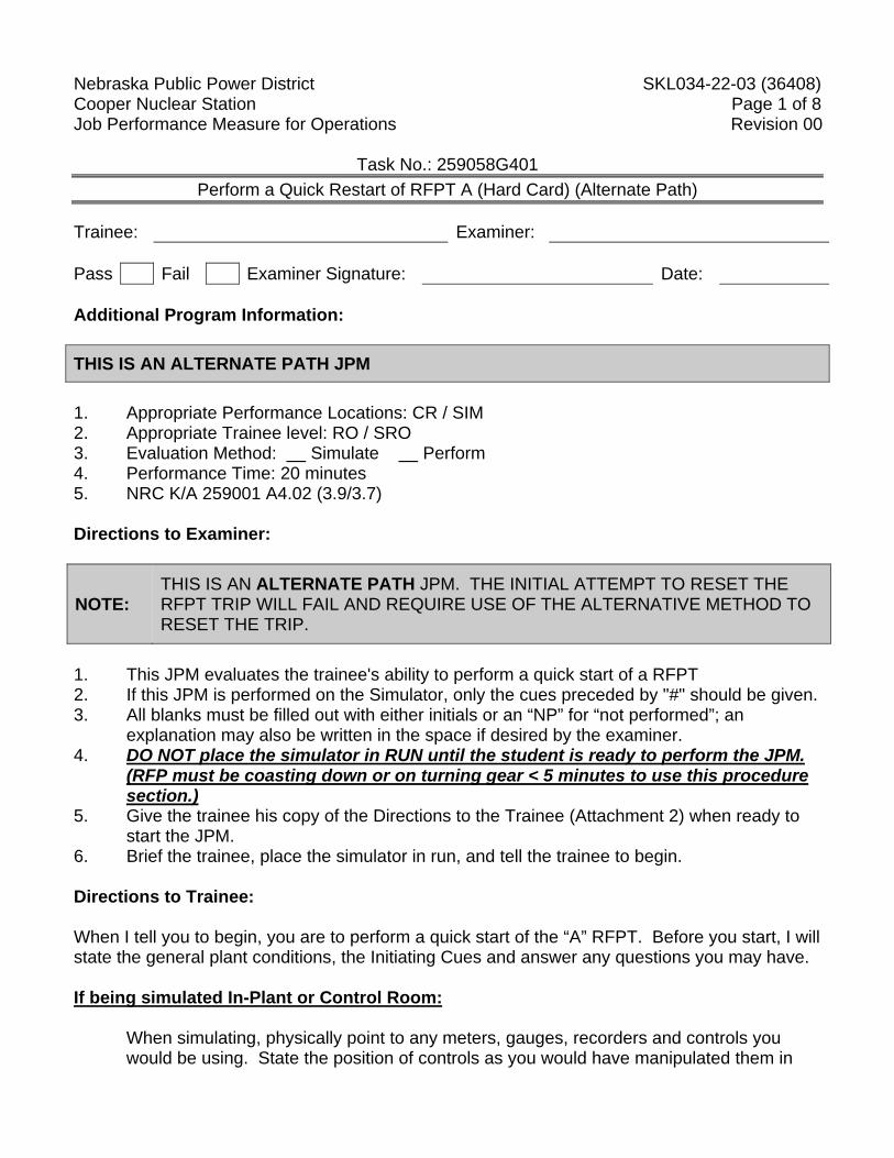
Nebraska Public Power District SKL034-22-03 (36408) Cooper Nuclear Station Page 1 of 8 Job Performance Measure for Operations Revision 00
Task No.: 259058G401 Perform a Quick Restart of RFPT A (Hard Card) (Alternate Path)
Trainee: Examiner: Pass Fail Examiner Signature: Date: Additional Program Information: THIS IS AN ALTERNATE PATH JPM 1. Appropriate Performance Locations: CR / SIM 2. Appropriate Trainee level: RO / SRO 3. Evaluation Method: Simulate Perform 4. Performance Time: 20 minutes 5. NRC K/A 259001 A4.02 (3.9/3.7) Directions to Examiner:
NOTE: THIS IS AN ALTERNATE PATH JPM. THE INITIAL ATTEMPT TO RESET THE RFPT TRIP WILL FAIL AND REQUIRE USE OF THE ALTERNATIVE METHOD TO RESET THE TRIP.
1. This JPM evaluates the trainee's ability to perform a quick start of a RFPT 2. If this JPM is performed on the Simulator, only the cues preceded by "#" should be given. 3. All blanks must be filled out with either initials or an “NP” for “not performed”; an
explanation may also be written in the space if desired by the examiner. 4. DO NOT place the simulator in RUN until the student is ready to perform the JPM.
(RFP must be coasting down or on turning gear < 5 minutes to use this procedure section.)
5. Give the trainee his copy of the Directions to the Trainee (Attachment 2) when ready to start the JPM.
6. Brief the trainee, place the simulator in run, and tell the trainee to begin. Directions to Trainee: When I tell you to begin, you are to perform a quick start of the “A” RFPT. Before you start, I will state the general plant conditions, the Initiating Cues and answer any questions you may have. If being simulated In-Plant or Control Room:
When simulating, physically point to any meters, gauges, recorders and controls you would be using. State the position of controls as you would have manipulated them in
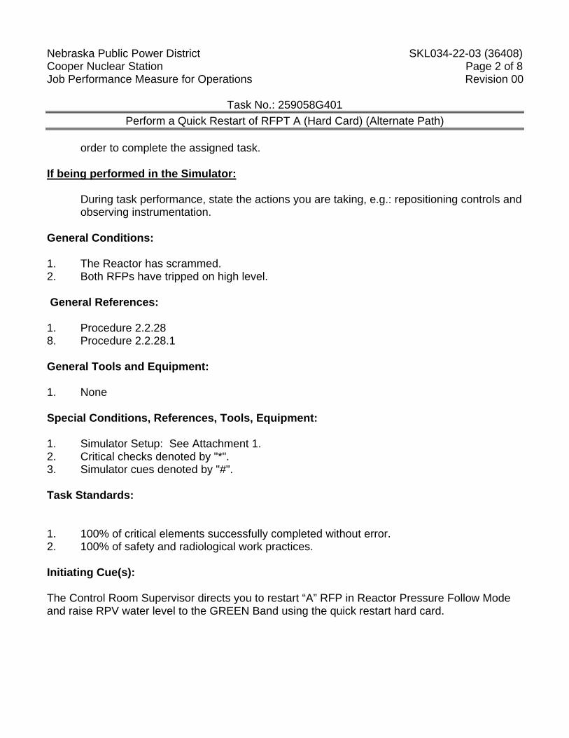
Nebraska Public Power District SKL034-22-03 (36408) Cooper Nuclear Station Page 2 of 8 Job Performance Measure for Operations Revision 00
Task No.: 259058G401 Perform a Quick Restart of RFPT A (Hard Card) (Alternate Path)
order to complete the assigned task.
If being performed in the Simulator:
During task performance, state the actions you are taking, e.g.: repositioning controls and observing instrumentation.
General Conditions: 1. The Reactor has scrammed. 2. Both RFPs have tripped on high level.
General References: 1. Procedure 2.2.28 8. Procedure 2.2.28.1 General Tools and Equipment: 1. None Special Conditions, References, Tools, Equipment: 1. Simulator Setup: See Attachment 1. 2. Critical checks denoted by "*". 3. Simulator cues denoted by "#". Task Standards: 1. 100% of critical elements successfully completed without error. 2. 100% of safety and radiological work practices. Initiating Cue(s): The Control Room Supervisor directs you to restart “A” RFP in Reactor Pressure Follow Mode and raise RPV water level to the GREEN Band using the quick restart hard card.
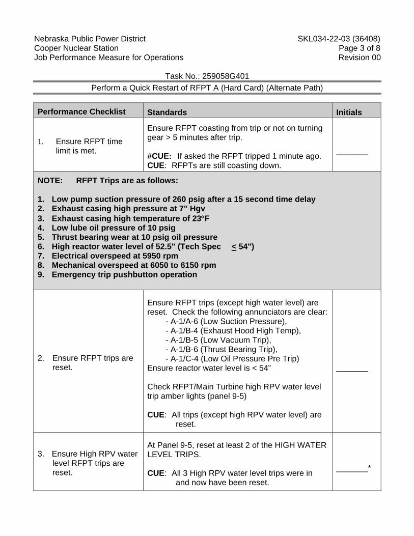
Nebraska Public Power District SKL034-22-03 (36408) Cooper Nuclear Station Page 3 of 8 Job Performance Measure for Operations Revision 00
Task No.: 259058G401 Perform a Quick Restart of RFPT A (Hard Card) (Alternate Path)
Performance Checklist Standards Initials
1. Ensure RFPT time limit is met.
Ensure RFPT coasting from trip or not on turning gear > 5 minutes after trip. #CUE: If asked the RFPT tripped 1 minute ago. CUE: RFPTs are still coasting down.
_______
NOTE: RFPT Trips are as follows: 1. Low pump suction pressure of 260 psig after a 15 second time delay 2. Exhaust casing high pressure at 7" Hgv 3. Exhaust casing high temperature of 23°F 4. Low lube oil pressure of 10 psig 5. Thrust bearing wear at 10 psig oil pressure 6. High reactor water level of 52.5" (Tech Spec � < 54") 7. Electrical overspeed at 5950 rpm 8. Mechanical overspeed at 6050 to 6150 rpm 9. Emergency trip pushbutton operation
2. Ensure RFPT trips are reset.
Ensure RFPT trips (except high water level) are reset. Check the following annunciators are clear:
- A-1/A-6 (Low Suction Pressure), - A-1/B-4 (Exhaust Hood High Temp), - A-1/B-5 (Low Vacuum Trip), - A-1/B-6 (Thrust Bearing Trip), - A-1/C-4 (Low Oil Pressure Pre Trip)
Ensure reactor water level is < 54” Check RFPT/Main Turbine high RPV water level trip amber lights (panel 9-5) CUE: All trips (except high RPV water level) are
reset.
_______
3. Ensure High RPV water level RFPT trips are reset.
At Panel 9-5, reset at least 2 of the HIGH WATER LEVEL TRIPS. CUE: All 3 High RPV water level trips were in
and now have been reset.
_______*
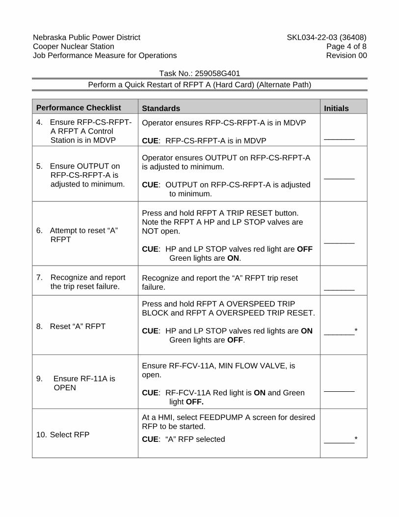
Nebraska Public Power District SKL034-22-03 (36408) Cooper Nuclear Station Page 4 of 8 Job Performance Measure for Operations Revision 00
Task No.: 259058G401 Perform a Quick Restart of RFPT A (Hard Card) (Alternate Path)
Performance Checklist Standards Initials
4. Ensure RFP-CS-RFPT-A RFPT A Control Station is in MDVP
Operator ensures RFP-CS-RFPT-A is in MDVP CUE: RFP-CS-RFPT-A is in MDVP
_______
5. Ensure OUTPUT on RFP-CS-RFPT-A is adjusted to minimum.
Operator ensures OUTPUT on RFP-CS-RFPT-A is adjusted to minimum. CUE: OUTPUT on RFP-CS-RFPT-A is adjusted
to minimum.
_______
6. Attempt to reset “A” RFPT
Press and hold RFPT A TRIP RESET button. Note the RFPT A HP and LP STOP valves are NOT open. CUE: HP and LP STOP valves red light are OFF
Green lights are ON.
_______
7. Recognize and report the trip reset failure.
Recognize and report the “A” RFPT trip reset failure.
_______
8. Reset “A” RFPT
Press and hold RFPT A OVERSPEED TRIP BLOCK and RFPT A OVERSPEED TRIP RESET. CUE: HP and LP STOP valves red lights are ON
Green lights are OFF.
_______*
9. Ensure RF-11A is OPEN
Ensure RF-FCV-11A, MIN FLOW VALVE, is open.
CUE: RF-FCV-11A Red light is ON and Green
light OFF.
_______
10. Select RFP
At a HMI, select FEEDPUMP A screen for desired RFP to be started. CUE: “A” RFP selected
_______*
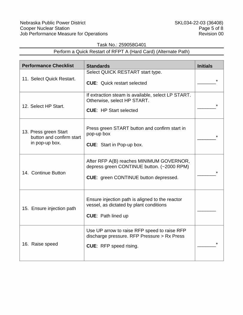
Nebraska Public Power District SKL034-22-03 (36408) Cooper Nuclear Station Page 5 of 8 Job Performance Measure for Operations Revision 00
Task No.: 259058G401 Perform a Quick Restart of RFPT A (Hard Card) (Alternate Path)
Performance Checklist Standards Initials
11. Select Quick Restart.
Select QUICK RESTART start type. CUE: Quick restart selected
_______*
12. Select HP Start.
If extraction steam is available, select LP START. Otherwise, select HP START.
CUE: HP Start selected
_______*
13. Press green Start button and confirm start in pop-up box.
Press green START button and confirm start in pop-up box CUE: Start in Pop-up box.
_______*
14. Continue Button
After RFP A(B) reaches MINIMUM GOVERNOR, depress green CONTINUE button. (~2000 RPM) CUE: green CONTINUE button depressed.
_______*
15. Ensure injection path
Ensure injection path is aligned to the reactor vessel, as dictated by plant conditions CUE: Path lined up
_______
16. Raise speed
Use UP arrow to raise RFP speed to raise RFP discharge pressure. RFP Pressure > Rx Press
CUE: RFP speed rising.
_______*
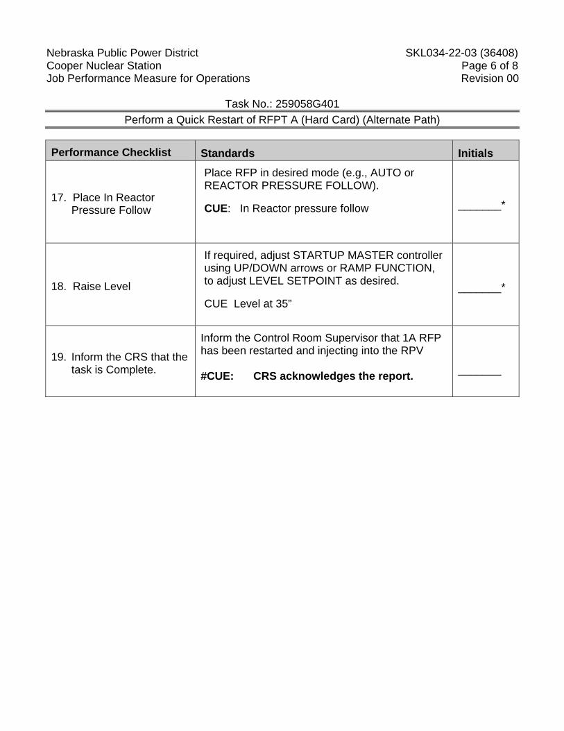
Nebraska Public Power District SKL034-22-03 (36408) Cooper Nuclear Station Page 6 of 8 Job Performance Measure for Operations Revision 00
Task No.: 259058G401 Perform a Quick Restart of RFPT A (Hard Card) (Alternate Path)
Performance Checklist Standards Initials
17. Place In Reactor Pressure Follow
Place RFP in desired mode (e.g., AUTO or REACTOR PRESSURE FOLLOW).
CUE: In Reactor pressure follow
_______*
18. Raise Level
If required, adjust STARTUP MASTER controller using UP/DOWN arrows or RAMP FUNCTION, to adjust LEVEL SETPOINT as desired.
CUE Level at 35” _______*
19. Inform the CRS that the task is Complete.
Inform the Control Room Supervisor that 1A RFP has been restarted and injecting into the RPV #CUE: CRS acknowledges the report.
_______
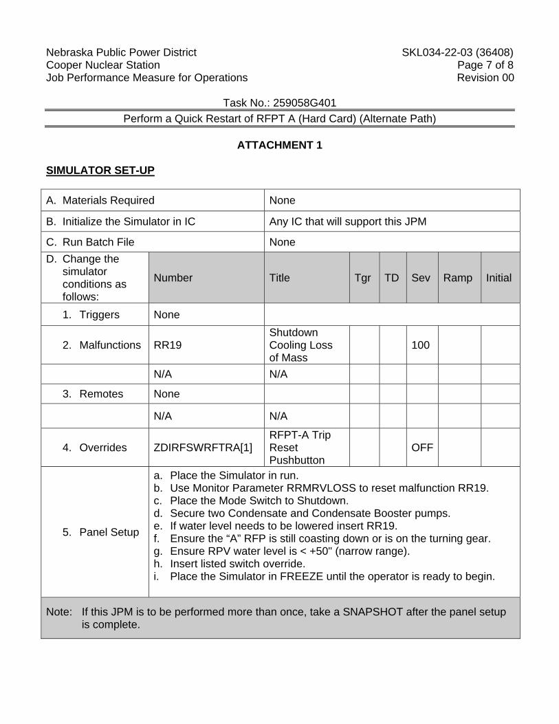
Nebraska Public Power District SKL034-22-03 (36408) Cooper Nuclear Station Page 7 of 8 Job Performance Measure for Operations Revision 00
Task No.: 259058G401 Perform a Quick Restart of RFPT A (Hard Card) (Alternate Path)
ATTACHMENT 1
SIMULATOR SET-UP A. Materials Required None
B. Initialize the Simulator in IC Any IC that will support this JPM
C. Run Batch File None D. Change the
simulator conditions as follows:
Number Title Tgr TD Sev Ramp Initial
1. Triggers None
2. Malfunctions RR19 Shutdown Cooling Loss of Mass
100
N/A N/A
3. Remotes None
N/A N/A
4. Overrides ZDIRFSWRFTRA[1] RFPT-A Trip Reset Pushbutton
OFF
5. Panel Setup
a. Place the Simulator in run. b. Use Monitor Parameter RRMRVLOSS to reset malfunction RR19. c. Place the Mode Switch to Shutdown. d. Secure two Condensate and Condensate Booster pumps. e. If water level needs to be lowered insert RR19. f. Ensure the “A” RFP is still coasting down or is on the turning gear. g. Ensure RPV water level is < +50" (narrow range). h. Insert listed switch override. i. Place the Simulator in FREEZE until the operator is ready to begin.
Note: If this JPM is to be performed more than once, take a SNAPSHOT after the panel setup is complete.
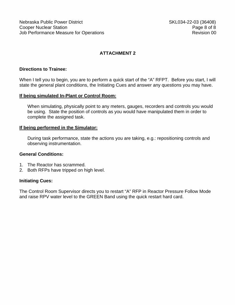
Nebraska Public Power District SKL034-22-03 (36408) Cooper Nuclear Station Page 8 of 8 Job Performance Measure for Operations Revision 00
ATTACHMENT 2 Directions to Trainee: When I tell you to begin, you are to perform a quick start of the “A” RFPT. Before you start, I will state the general plant conditions, the Initiating Cues and answer any questions you may have. If being simulated In-Plant or Control Room:
When simulating, physically point to any meters, gauges, recorders and controls you would be using. State the position of controls as you would have manipulated them in order to complete the assigned task.
If being performed in the Simulator:
During task performance, state the actions you are taking, e.g.: repositioning controls and observing instrumentation.
General Conditions: 1. The Reactor has scrammed. 2. Both RFPs have tripped on high level. Initiating Cues: The Control Room Supervisor directs you to restart “A” RFP in Reactor Pressure Follow Mode and raise RPV water level to the GREEN Band using the quick restart hard card.
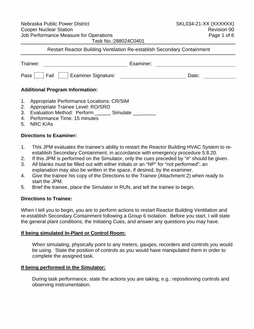
Nebraska Public Power District SKL034-21-XX (XXXXXX) Cooper Nuclear Station Revision 00 Job Performance Measure for Operations Page 1 of 6 Task No.:288024C0401
Restart Reactor Building Ventilation Re-establish Secondary Containment
Trainee: Examiner: Pass Fail Examiner Signature: Date: Additional Program Information: 1. Appropriate Performance Locations: CR/SIM 2. Appropriate Trainee Level: RO/SRO 3. Evaluation Method: Perform _ Simulate ___ 4. Performance Time: 15 minutes 5. NRC K/As Directions to Examiner: 1. This JPM evaluates the trainee’s ability to restart the Reactor Building HVAC System to re-
establish Secondary Containment, in accordance with emergency procedure 5.8.20. 2. If this JPM is performed on the Simulator, only the cues preceded by “#” should be given. 3. All blanks must be filled out with either initials or an “NP” for “not performed”; an
explanation may also be written in the space, if desired, by the examiner. 4. Give the trainee his copy of the Directions to the Trainee (Attachment 2) when ready to
start the JPM. 5. Brief the trainee, place the Simulator in RUN, and tell the trainee to begin. Directions to Trainee: When I tell you to begin, you are to perform actions to restart Reactor Building Ventilation and re-establish Secondary Containment following a Group 6 Isolation. Before you start, I will state the general plant conditions, the Initiating Cues, and answer any questions you may have. If being simulated In-Plant or Control Room:
When simulating, physically point to any meters, gauges, recorders and controls you would be using. State the position of controls as you would have manipulated them in order to complete the assigned task.
If being performed in the Simulator:
During task performance, state the actions you are taking, e.g.: repositioning controls and observing instrumentation.
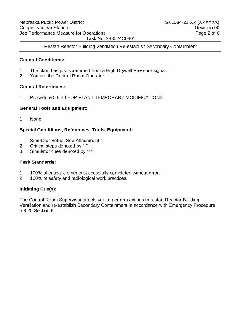
Nebraska Public Power District SKL034-21-XX (XXXXXX) Cooper Nuclear Station Revision 00 Job Performance Measure for Operations Page 2 of 6 Task No.:288024C0401
Restart Reactor Building Ventilation Re-establish Secondary Containment
General Conditions: 1. The plant has just scrammed from a High Drywell Pressure signal. 2. You are the Control Room Operator. General References: 1. Procedure 5.8.20 EOP PLANT TEMPORARY MODIFICATIONS General Tools and Equipment: 1. None Special Conditions, References, Tools, Equipment: 1. Simulator Setup: See Attachment 1. 2. Critical steps denoted by “*”. 3. Simulator cues denoted by “#”. Task Standards: 1. 100% of critical elements successfully completed without error. 2. 100% of safety and radiological work practices. Initiating Cue(s): The Control Room Supervisor directs you to perform actions to restart Reactor Building Ventilation and re-establish Secondary Containment in accordance with Emergency Procedure 5.8.20 Section 6.
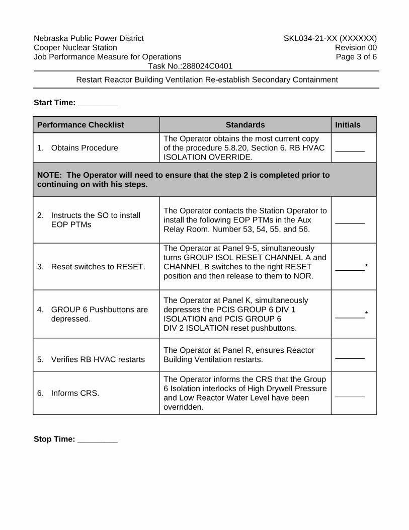
Nebraska Public Power District SKL034-21-XX (XXXXXX) Cooper Nuclear Station Revision 00 Job Performance Measure for Operations Page 3 of 6 Task No.:288024C0401
Restart Reactor Building Ventilation Re-establish Secondary Containment
Start Time: _________ Performance Checklist Standards Initials
1. Obtains Procedure The Operator obtains the most current copy of the procedure 5.8.20, Section 6. RB HVAC ISOLATION OVERRIDE.
NOTE: The Operator will need to ensure that the step 2 is completed prior to continuing on with his steps.
2. Instructs the SO to install EOP PTMs
The Operator contacts the Station Operator to install the following EOP PTMs in the Aux Relay Room. Number 53, 54, 55, and 56.
3. Reset switches to RESET.
The Operator at Panel 9-5, simultaneously turns GROUP ISOL RESET CHANNEL A and CHANNEL B switches to the right RESET position and then release to them to NOR.
*
4. GROUP 6 Pushbuttons are depressed.
The Operator at Panel K, simultaneously depresses the PCIS GROUP 6 DIV 1 ISOLATION and PCIS GROUP 6 DIV 2 ISOLATION reset pushbuttons.
*
5. Verifies RB HVAC restarts
The Operator at Panel R, ensures Reactor Building Ventilation restarts.
6. Informs CRS.
The Operator informs the CRS that the Group 6 Isolation interlocks of High Drywell Pressure and Low Reactor Water Level have been overridden.
Stop Time: _________
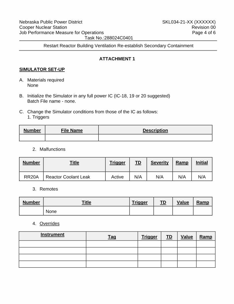
Nebraska Public Power District SKL034-21-XX (XXXXXX) Cooper Nuclear Station Revision 00 Job Performance Measure for Operations Page 4 of 6 Task No.:288024C0401
Restart Reactor Building Ventilation Re-establish Secondary Containment
ATTACHMENT 1
SIMULATOR SET-UP A. Materials required
None B. Initialize the Simulator in any full power IC (IC-18, 19 or 20 suggested)
Batch File name - none. C. Change the Simulator conditions from those of the IC as follows:
1. Triggers Number
File Name Description
2. Malfunctions Number
Title Trigger TD Severity
Ramp Initial
RR20A
Reactor Coolant Leak Active N/A N/A
N/A N/A
3. Remotes
Number
Title Trigger TD
Value Ramp
None
4. Overrides
Instrument
Tag Trigger TD Value Ramp
Nebraska Public Power District SKL034-21-XX (XXXXXX) Cooper Nuclear Station Revision 00 Job Performance Measure for Operations Page 5 of 6 Task No.:288024C0401
Restart Reactor Building Ventilation Re-establish Secondary Containment
5. Panel Set-up (suggested.)
a. Insert listed overrides and malfunctions. b. Place the Simulator in RUN. c. When the High DW Pressure Group 6 is received freeze the simulator.
Note: If this JPM is to be performed more than once, snap the Simulator into an IC after the panel set-up is complete.
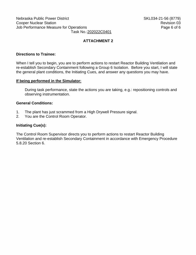
Nebraska Public Power District SKL034-21-56 (8779) Cooper Nuclear Station Revision 03 Job Performance Measure for Operations Page 6 of 6 Task No.:202022C0401
ATTACHMENT 2
Directions to Trainee: When I tell you to begin, you are to perform actions to restart Reactor Building Ventilation and re-establish Secondary Containment following a Group 6 Isolation. Before you start, I will state the general plant conditions, the Initiating Cues, and answer any questions you may have. If being performed in the Simulator:
During task performance, state the actions you are taking, e.g.: repositioning controls and observing instrumentation.
General Conditions: 1. The plant has just scrammed from a High Drywell Pressure signal. 2. You are the Control Room Operator. Initiating Cue(s): The Control Room Supervisor directs you to perform actions to restart Reactor Building Ventilation and re-establish Secondary Containment in accordance with Emergency Procedure 5.8.20 Section 6.
Nebraska Public Power District SKL034-20-107(22658) Cooper Nuclear Station Page 1 of 6 Job Performance Measure for Operations Revision 03
Task No.: 249005P0401 Lowering DEH pressure setpoint (Alternate Path)
Trainee: Examiner: Pass Fail Examiner Signature: Date: THIS IS AN ALTERNATE PATH JPM Additional Program Information: 1. Appropriate Performance Locations: SIM 2. Appropriate Trainee level: RO / SRO 3. Evaluation Method: Perform 4. Performance Time: 15 minutes 5. NRC K/A 241000 A4.06 (3.9/3.9) Directions to Examiner: NOTE: THIS IS AN ALTERNATE PATH JPM. During Pressure reduction the DEH
Throttle Pressure signals will fail causing Pressure Set-point to fail to respond. 1. This JPM evaluates the trainee's ability to manipulate the DEH controls in order to lower
reactor pressure during a Cooldown. 2. The examiner is to obtain the AJPM Comment Form@ (Attachment C of ODG 206) prior
to administering the JPM. 3. If this JPM is performed on the Simulator, only the cues preceded by "#" should be given. 4. Observe the trainee during performance of the JPM for proper use of self-checking
methods. 5. All blanks must be filled out with either initials or an ANP@ for Anot performed@; an
explanation may also be written in the space if desired by the examiner. 6. Brief the trainee, place the simulator in run, and tell the trainee to begin. Directions to Trainee: When I tell you to begin, you are to lower reactor pressure to 800 psig at a rate of 10 psig /min using the hard card. Before you start, I will state the general plant conditions, the Initiating Cues and answer any questions you may have. During task performance, state the actions you are taking, e.g.: repositioning controls and observing instrumentation.
Nebraska Public Power District SKL034-20-107(22658) Cooper Nuclear Station Page 2 of 6 Job Performance Measure for Operations Revision 03
Task No.: 249005P0401 Lowering DEH pressure setpoint (Alternate Path)
General Conditions: 1. The plant has scrammed and pressure is approximately 930 psig. 2. The CRS Orders you to lower Reactor Pressure to 800 Psig at a rate of 10 psig/min using
the DEH hard card.
General References: 1. Procedure 2.2.77.1 (hard card) General Tools and Equipment: 1. None Special Conditions, References, Tools, Equipment: 1. Simulator Setup: See Attachment 1. 2. Critical checks denoted by "*". Task Standards: 1. 100% of critical elements successfully completed without error. 2. 100% of safety and radiological work practices. Initiating Cue(s): The CRS Orders you to lower Reactor Pressure to 800 Psig at a rate of 10 psig/min using the hard card. Inform the CRS when the Reactor is at 800 psig.
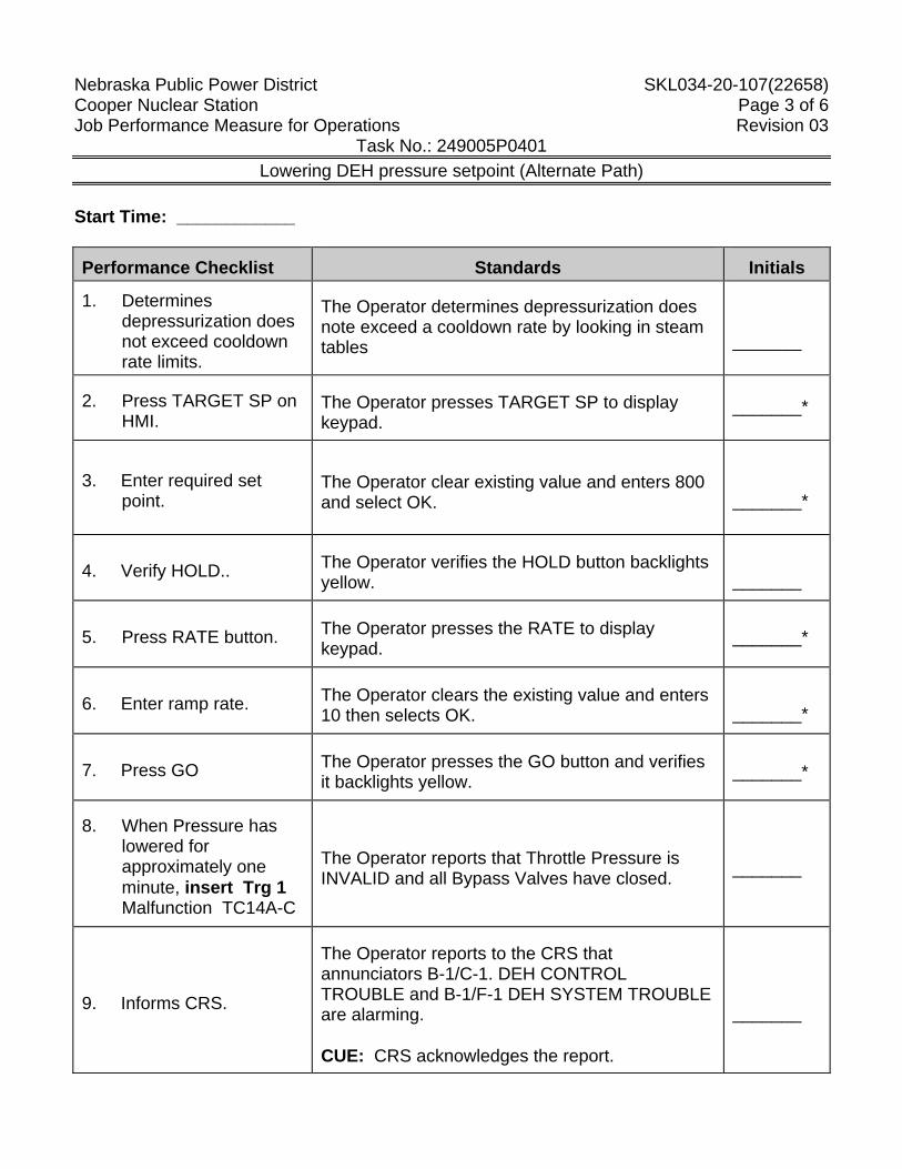
Nebraska Public Power District SKL034-20-107(22658) Cooper Nuclear Station Page 3 of 6 Job Performance Measure for Operations Revision 03
Task No.: 249005P0401 Lowering DEH pressure setpoint (Alternate Path)
Start Time: ____________
Performance Checklist Standards Initials
1. Determines depressurization does not exceed cooldown rate limits.
The Operator determines depressurization does note exceed a cooldown rate by looking in steam tables
_______
2. Press TARGET SP on HMI.
The Operator presses TARGET SP to display keypad.
_______*
3. Enter required set point.
The Operator clear existing value and enters 800 and select OK.
_______*
4. Verify HOLD.. The Operator verifies the HOLD button backlights yellow.
_______
5. Press RATE button. The Operator presses the RATE to display keypad. _______*
6. Enter ramp rate. The Operator clears the existing value and enters 10 then selects OK.
_______*
7. Press GO The Operator presses the GO button and verifies it backlights yellow. _______*
8. When Pressure has lowered for approximately one minute, insert Trg 1 Malfunction TC14A-C
The Operator reports that Throttle Pressure is INVALID and all Bypass Valves have closed. _______
9. Informs CRS.
The Operator reports to the CRS that annunciators B-1/C-1. DEH CONTROL TROUBLE and B-1/F-1 DEH SYSTEM TROUBLE are alarming. CUE: CRS acknowledges the report.
_______
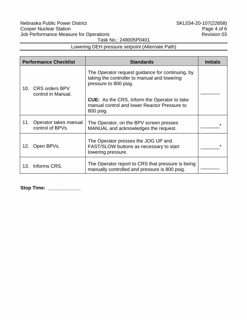
Nebraska Public Power District SKL034-20-107(22658) Cooper Nuclear Station Page 4 of 6 Job Performance Measure for Operations Revision 03
Task No.: 249005P0401 Lowering DEH pressure setpoint (Alternate Path)
Performance Checklist Standards Initials
10. CRS orders BPV control in Manual.
The Operator request guidance for continuing, by taking the controller to manual and lowering pressure to 800 psig.
CUE: As the CRS, Inform the Operator to take manual control and lower Reactor Pressure to 800 psig.
_______
11. Operator takes manual control of BPVs.
The Operator, on the BPV screen presses MANUAL and acknowledges the request. _______*
12. Open BPVs. The Operator presses the JOG UP and FAST/SLOW buttons as necessary to start lowering pressure.
_______*
13. Informs CRS. The Operator report to CRS that pressure is being manually controlled and pressure is 800 psig. _______
Stop Time: ____________
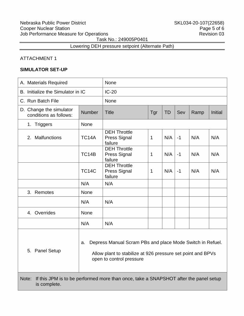
Nebraska Public Power District SKL034-20-107(22658) Cooper Nuclear Station Page 5 of 6 Job Performance Measure for Operations Revision 03
Task No.: 249005P0401 Lowering DEH pressure setpoint (Alternate Path)
ATTACHMENT 1 SIMULATOR SET-UP A. Materials Required None
B. Initialize the Simulator in IC IC-20
C. Run Batch File None
D. Change the simulator conditions as follows: Number Title Tgr TD Sev Ramp Initial
1. Triggers None
2. Malfunctions TC14A DEH Throttle Press Signal failure
1 N/A -1 N/A N/A
TC14B DEH Throttle Press Signal failure
1 N/A -1 N/A N/A
TC14C DEH Throttle Press Signal failure
1 N/A -1 N/A N/A
N/A N/A
3. Remotes None
N/A N/A
4. Overrides None
N/A N/A
5. Panel Setup
a. Depress Manual Scram PBs and place Mode Switch in Refuel. Allow plant to stabilize at 926 pressure set point and BPVs
open to control pressure
Note: If this JPM is to be performed more than once, take a SNAPSHOT after the panel setup is complete.
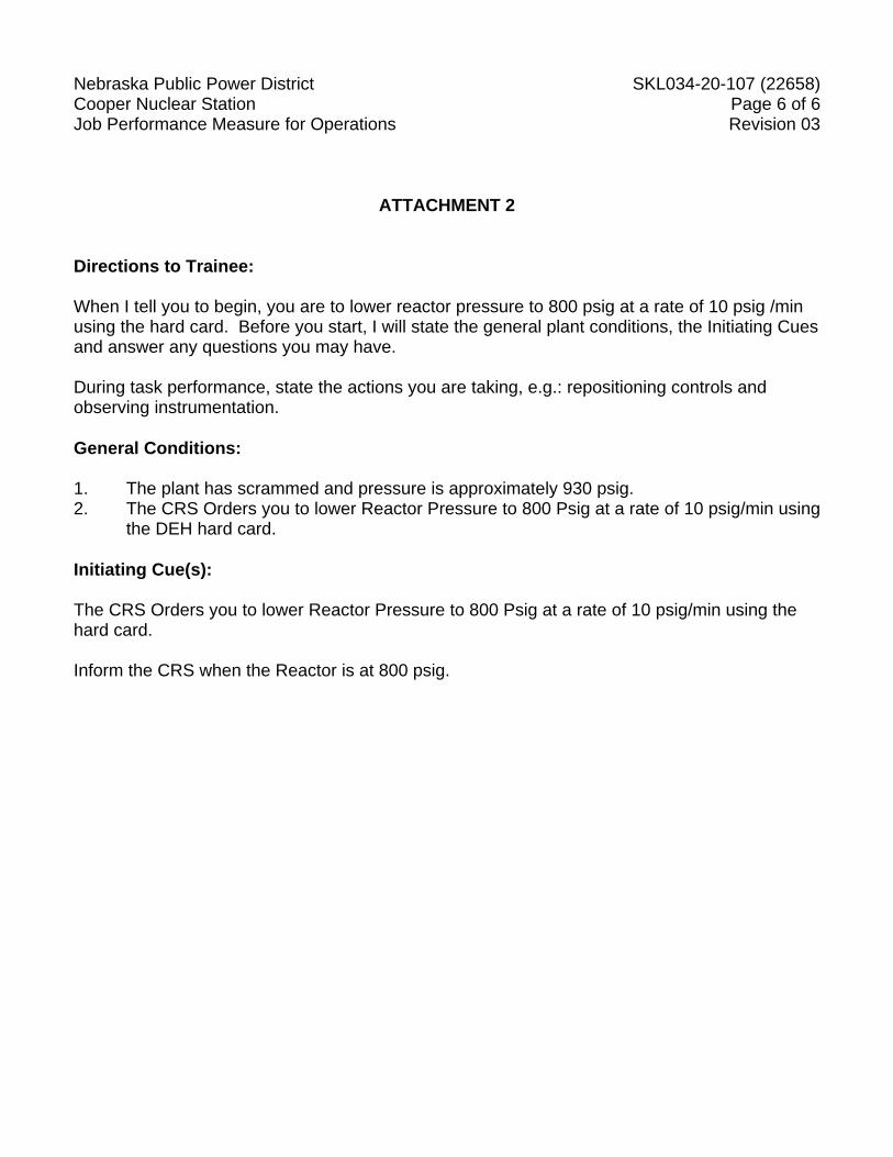
Nebraska Public Power District SKL034-20-107 (22658) Cooper Nuclear Station Page 6 of 6 Job Performance Measure for Operations Revision 03
ATTACHMENT 2 Directions to Trainee: When I tell you to begin, you are to lower reactor pressure to 800 psig at a rate of 10 psig /min using the hard card. Before you start, I will state the general plant conditions, the Initiating Cues and answer any questions you may have. During task performance, state the actions you are taking, e.g.: repositioning controls and observing instrumentation.
General Conditions: 1. The plant has scrammed and pressure is approximately 930 psig. 2. The CRS Orders you to lower Reactor Pressure to 800 Psig at a rate of 10 psig/min using
the DEH hard card.
Initiating Cue(s): The CRS Orders you to lower Reactor Pressure to 800 Psig at a rate of 10 psig/min using the hard card. Inform the CRS when the Reactor is at 800 psig.
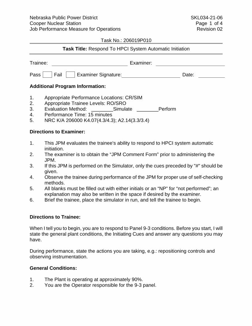
Nebraska Public Power District SKL034-21-06 Cooper Nuclear Station Page 1 of 4 Job Performance Measure for Operations Revision 02
Task No.: 206019P010
Task Title: Respond To HPCI System Automatic Initiation
Trainee: Examiner: Pass Fail Examiner Signature: Date: Additional Program Information: 1. Appropriate Performance Locations: CR/SIM 2. Appropriate Trainee Levels: RO/SRO 3. Evaluation Method: Simulate Perform 4. Performance Time: 15 minutes 5. NRC K/A 206000 K4.07(4.3/4.3); A2.14(3.3/3.4) Directions to Examiner: 1. This JPM evaluates the trainee's ability to respond to HPCI system automatic
initiation. 2. The examiner is to obtain the “JPM Comment Form” prior to administering the
JPM. 3. If this JPM is performed on the Simulator, only the cues preceded by "#" should be
given. 4. Observe the trainee during performance of the JPM for proper use of self-checking
methods. 5. All blanks must be filled out with either initials or an “NP” for “not performed”; an
explanation may also be written in the space if desired by the examiner. 6. Brief the trainee, place the simulator in run, and tell the trainee to begin. Directions to Trainee: When I tell you to begin, you are to respond to Panel 9-3 conditions. Before you start, I will state the general plant conditions, the Initiating Cues and answer any questions you may have. During performance, state the actions you are taking, e.g.: repositioning controls and observing instrumentation. General Conditions: 1. The Plant is operating at approximately 90%. 2. You are the Operator responsible for the 9-3 panel.
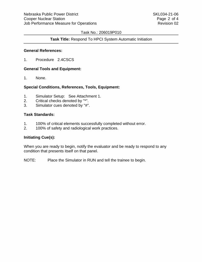
Nebraska Public Power District SKL034-21-06 Cooper Nuclear Station Page 2 of 4 Job Performance Measure for Operations Revision 02
Task No.: 206019P010
Task Title: Respond To HPCI System Automatic Initiation
General References: 1. Procedure 2.4CSCS General Tools and Equipment: 1. None. Special Conditions, References, Tools, Equipment: 1. Simulator Setup: See Attachment 1. 2. Critical checks denoted by "*". 3. Simulator cues denoted by "#". Task Standards: 1. 100% of critical elements successfully completed without error. 2. 100% of safety and radiological work practices. Initiating Cue(s): When you are ready to begin, notify the evaluator and be ready to respond to any condition that presents itself on that panel. NOTE: Place the Simulator in RUN and tell the trainee to begin.
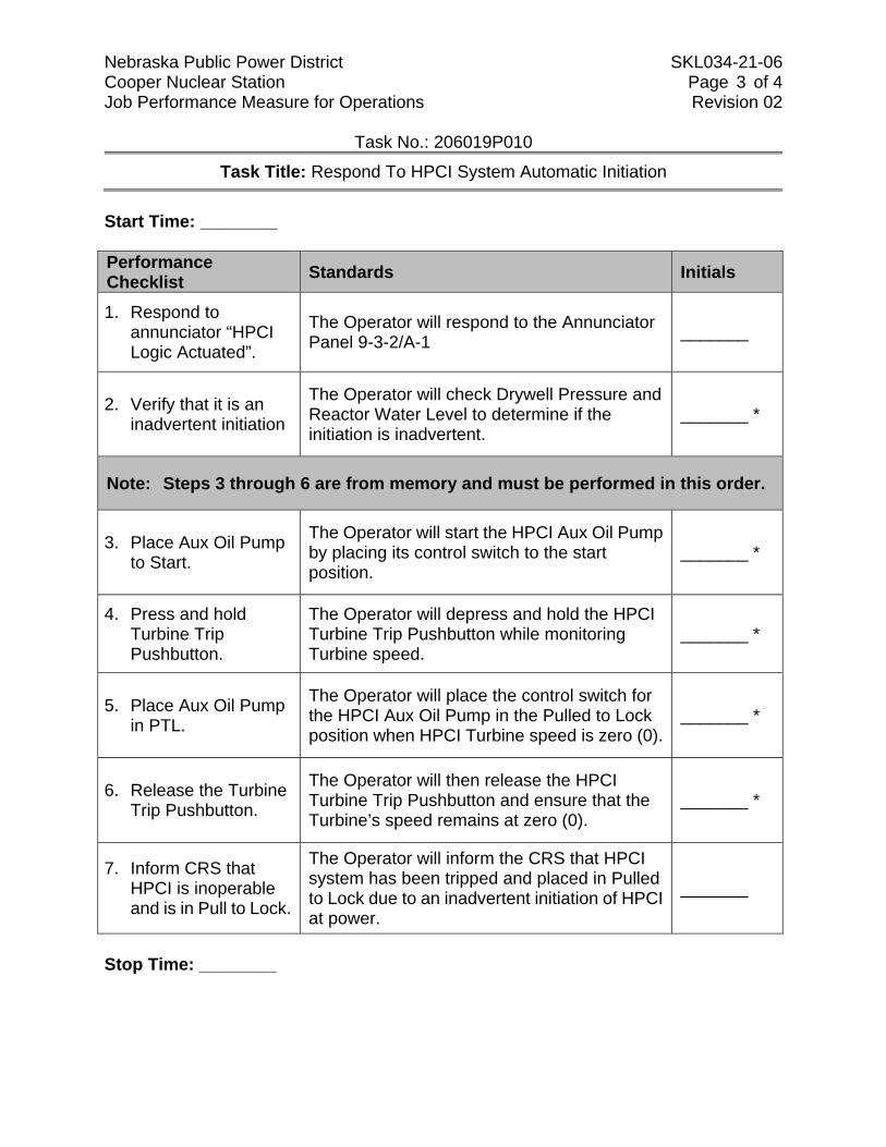
Nebraska Public Power District SKL034-21-06 Cooper Nuclear Station Page 3 of 4 Job Performance Measure for Operations Revision 02
Task No.: 206019P010
Task Title: Respond To HPCI System Automatic Initiation
Start Time: ________ Performance Checklist Standards Initials
1. Respond to annunciator “HPCI Logic Actuated”.
The Operator will respond to the Annunciator Panel 9-3-2/A-1 _______
2. Verify that it is an inadvertent initiation
The Operator will check Drywell Pressure and Reactor Water Level to determine if the initiation is inadvertent.
_______ *
Note: Steps 3 through 6 are from memory and must be performed in this order.
3. Place Aux Oil Pump to Start.
The Operator will start the HPCI Aux Oil Pump by placing its control switch to the start position.
_______ *
4. Press and hold Turbine Trip Pushbutton.
The Operator will depress and hold the HPCI Turbine Trip Pushbutton while monitoring Turbine speed.
_______ *
5. Place Aux Oil Pump in PTL.
The Operator will place the control switch for the HPCI Aux Oil Pump in the Pulled to Lock position when HPCI Turbine speed is zero (0).
_______ *
6. Release the Turbine Trip Pushbutton.
The Operator will then release the HPCI Turbine Trip Pushbutton and ensure that the Turbine’s speed remains at zero (0).
_______ *
7. Inform CRS that HPCI is inoperable and is in Pull to Lock.
The Operator will inform the CRS that HPCI system has been tripped and placed in Pulled to Lock due to an inadvertent initiation of HPCI at power.
_______
Stop Time: ________
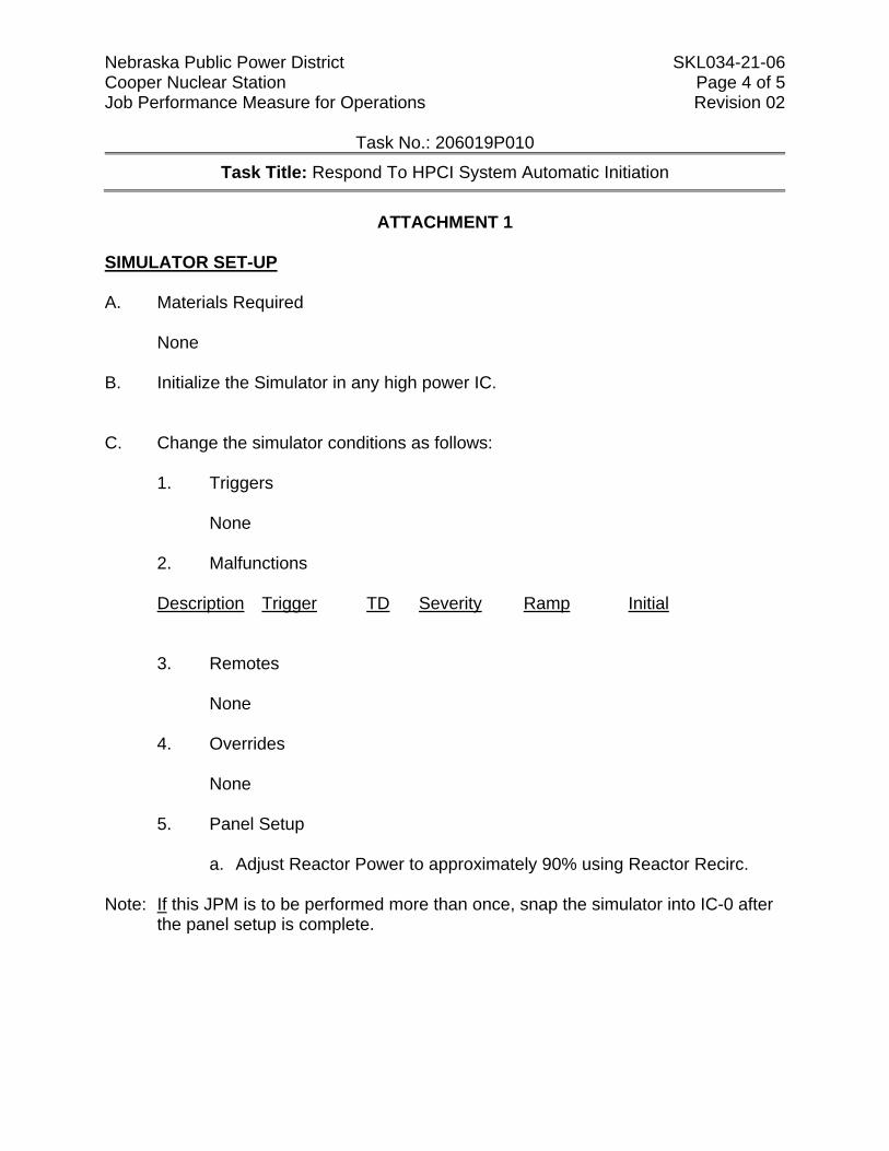
Nebraska Public Power District SKL034-21-06 Cooper Nuclear Station Page 4 of 5 Job Performance Measure for Operations Revision 02
Task No.: 206019P010
Task Title: Respond To HPCI System Automatic Initiation
ATTACHMENT 1
SIMULATOR SET-UP A. Materials Required
None B. Initialize the Simulator in any high power IC. C. Change the simulator conditions as follows:
1. Triggers
None
2. Malfunctions
Description Trigger TD Severity Ramp Initial
3. Remotes
None
4. Overrides
None
5. Panel Setup
a. Adjust Reactor Power to approximately 90% using Reactor Recirc. Note: If this JPM is to be performed more than once, snap the simulator into IC-0 after
the panel setup is complete.
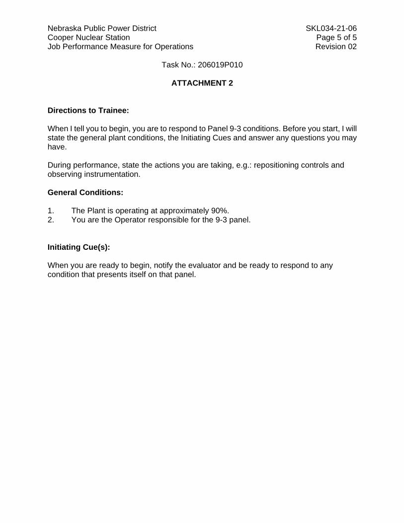
Nebraska Public Power District SKL034-21-06 Cooper Nuclear Station Page 5 of 5 Job Performance Measure for Operations Revision 02
Task No.: 206019P010
ATTACHMENT 2 Directions to Trainee: When I tell you to begin, you are to respond to Panel 9-3 conditions. Before you start, I will state the general plant conditions, the Initiating Cues and answer any questions you may have. During performance, state the actions you are taking, e.g.: repositioning controls and observing instrumentation. General Conditions: 1. The Plant is operating at approximately 90%. 2. You are the Operator responsible for the 9-3 panel. Initiating Cue(s): When you are ready to begin, notify the evaluator and be ready to respond to any condition that presents itself on that panel.
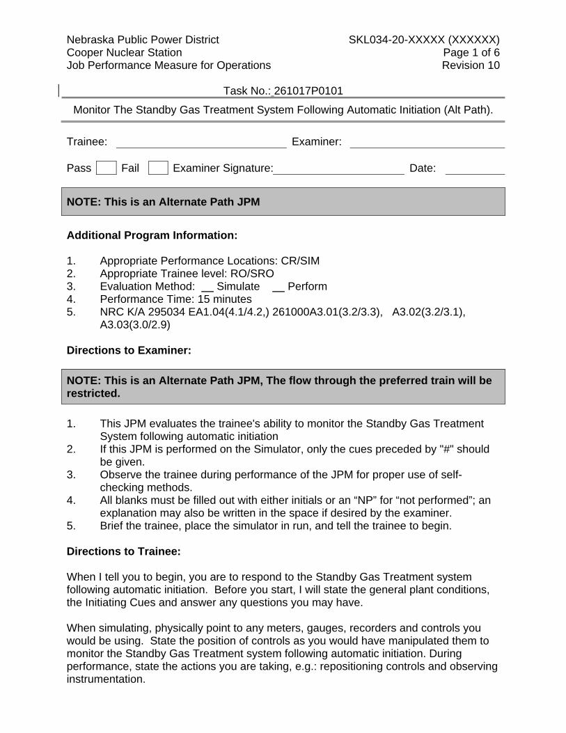
Nebraska Public Power District SKL034-20-XXXXX (XXXXXX) Cooper Nuclear Station Page 1 of 6 Job Performance Measure for Operations Revision 10
Task No.: 261017P0101
Monitor The Standby Gas Treatment System Following Automatic Initiation (Alt Path).
Trainee: Examiner: Pass Fail Examiner Signature: Date:
NOTE: This is an Alternate Path JPM
Additional Program Information: 1. Appropriate Performance Locations: CR/SIM 2. Appropriate Trainee level: RO/SRO 3. Evaluation Method: Simulate Perform 4. Performance Time: 15 minutes 5. NRC K/A 295034 EA1.04(4.1/4.2,) 261000A3.01(3.2/3.3), A3.02(3.2/3.1),
A3.03(3.0/2.9) Directions to Examiner: NOTE: This is an Alternate Path JPM, The flow through the preferred train will be restricted. 1. This JPM evaluates the trainee's ability to monitor the Standby Gas Treatment
System following automatic initiation 2. If this JPM is performed on the Simulator, only the cues preceded by "#" should
be given. 3. Observe the trainee during performance of the JPM for proper use of self-
checking methods. 4. All blanks must be filled out with either initials or an “NP” for “not performed”; an
explanation may also be written in the space if desired by the examiner. 5. Brief the trainee, place the simulator in run, and tell the trainee to begin. Directions to Trainee: When I tell you to begin, you are to respond to the Standby Gas Treatment system following automatic initiation. Before you start, I will state the general plant conditions, the Initiating Cues and answer any questions you may have. When simulating, physically point to any meters, gauges, recorders and controls you would be using. State the position of controls as you would have manipulated them to monitor the Standby Gas Treatment system following automatic initiation. During performance, state the actions you are taking, e.g.: repositioning controls and observing instrumentation.
Nebraska Public Power District SKL034-20-XXXXX (XXXXXX) Cooper Nuclear Station Page 2 of 6 Job Performance Measure for Operations Revision 10
Task No.: 261017P0101
Monitor The Standby Gas Treatment System Following Automatic Initiation (Alt Path).
General Conditions: 1. The plant is Shutdown. 2. A Spurious Group 6 isolation due occurred 10 minutes ago. 3. Procedure 2.1.22, Recovering from a Group Isolation, is in progress and requires
the performance of procedure 2.2.73.
General References: 1. Procedure 2.1.22 2. Procedure 2.2.73 General Tools and Equipment: 1. None Special Conditions, References, Tools, Equipment: 1. Simulator Setup: See Attachment 1. 2. Critical checks denoted by "*". 3. Simulator cues denoted by "#". Task Standards: 1. 100% of critical elements successfully completed without error. 2. 100% of safety and radiological work practices. Initiating Cue(s): The Control Room Supervisor directs you to respond to an automatic initiation of the Standby Gas Treatment System per procedure 2.2.73. Inform the CRS when proper operation of standby gas treatment has been verified. NOTE: Place the Simulator in RUN and tell the trainee to begin.
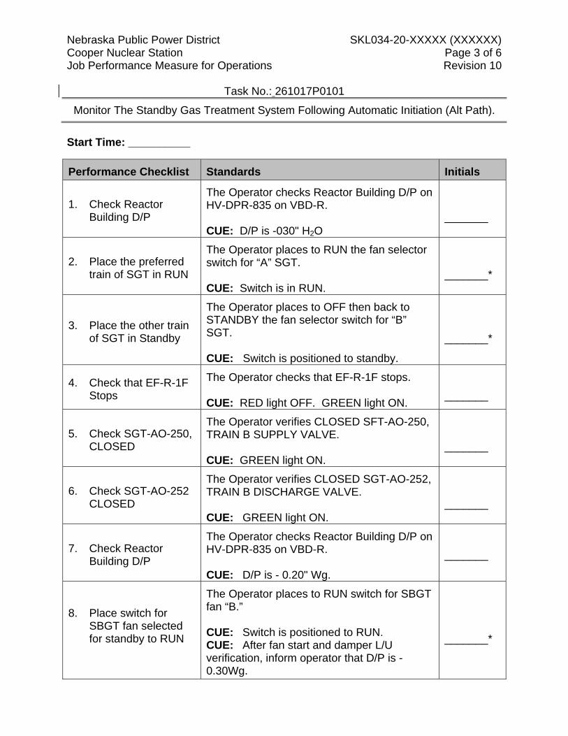
Nebraska Public Power District SKL034-20-XXXXX (XXXXXX) Cooper Nuclear Station Page 3 of 6 Job Performance Measure for Operations Revision 10
Task No.: 261017P0101
Monitor The Standby Gas Treatment System Following Automatic Initiation (Alt Path).
Start Time: __________
Performance Checklist Standards Initials
1. Check Reactor Building D/P
The Operator checks Reactor Building D/P on HV-DPR-835 on VBD-R. CUE: D/P is -030" H2O
_______
2. Place the preferred train of SGT in RUN
The Operator places to RUN the fan selector switch for “A” SGT. CUE: Switch is in RUN.
_______*
3. Place the other train of SGT in Standby
The Operator places to OFF then back to STANDBY the fan selector switch for “B” SGT. CUE: Switch is positioned to standby.
_______*
4. Check that EF-R-1F Stops
The Operator checks that EF-R-1F stops. CUE: RED light OFF. GREEN light ON.
_______
5. Check SGT-AO-250, CLOSED
The Operator verifies CLOSED SFT-AO-250, TRAIN B SUPPLY VALVE. CUE: GREEN light ON.
_______
6. Check SGT-AO-252 CLOSED
The Operator verifies CLOSED SGT-AO-252, TRAIN B DISCHARGE VALVE. CUE: GREEN light ON.
_______
7. Check Reactor Building D/P
The Operator checks Reactor Building D/P on HV-DPR-835 on VBD-R. CUE: D/P is - 0.20" Wg.
_______
8. Place switch for SBGT fan selected for standby to RUN
The Operator places to RUN switch for SBGT fan “B.” CUE: Switch is positioned to RUN. CUE: After fan start and damper L/U verification, inform operator that D/P is -0.30Wg.
_______*
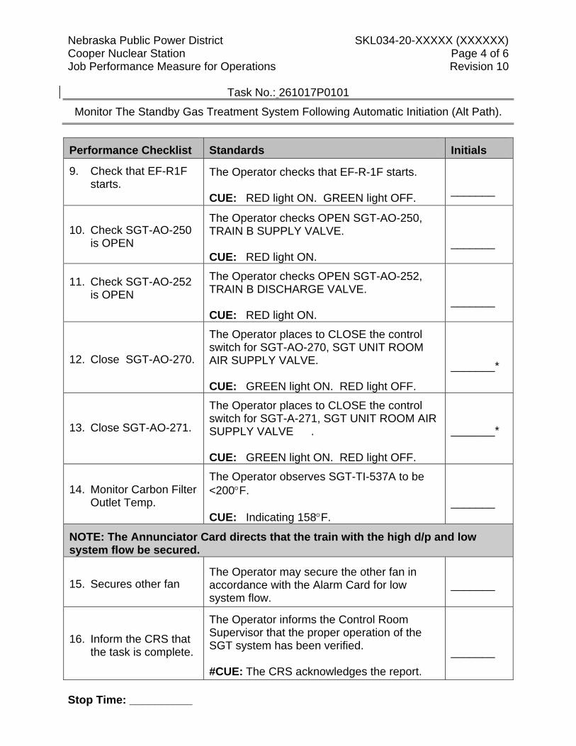
Nebraska Public Power District SKL034-20-XXXXX (XXXXXX) Cooper Nuclear Station Page 4 of 6 Job Performance Measure for Operations Revision 10
Task No.: 261017P0101
Monitor The Standby Gas Treatment System Following Automatic Initiation (Alt Path).
Performance Checklist Standards Initials
9. Check that EF-R1F starts.
The Operator checks that EF-R-1F starts. CUE: RED light ON. GREEN light OFF.
_______
10. Check SGT-AO-250 is OPEN
The Operator checks OPEN SGT-AO-250, TRAIN B SUPPLY VALVE. CUE: RED light ON.
_______
11. Check SGT-AO-252 is OPEN
The Operator checks OPEN SGT-AO-252, TRAIN B DISCHARGE VALVE. CUE: RED light ON.
_______
12. Close SGT-AO-270.
The Operator places to CLOSE the control switch for SGT-AO-270, SGT UNIT ROOM AIR SUPPLY VALVE. CUE: GREEN light ON. RED light OFF.
_______*
13. Close SGT-AO-271.
The Operator places to CLOSE the control switch for SGT-A-271, SGT UNIT ROOM AIR SUPPLY VALVE . CUE: GREEN light ON. RED light OFF.
_______*
14. Monitor Carbon Filter Outlet Temp.
The Operator observes SGT-TI-537A to be <200°F. CUE: Indicating 158°F.
_______
NOTE: The Annunciator Card directs that the train with the high d/p and low system flow be secured.
15. Secures other fan The Operator may secure the other fan in accordance with the Alarm Card for low system flow.
_______
16. Inform the CRS that the task is complete.
The Operator informs the Control Room Supervisor that the proper operation of the SGT system has been verified. #CUE: The CRS acknowledges the report.
_______
Stop Time: __________
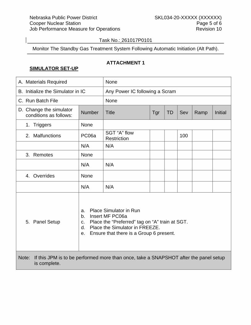
Nebraska Public Power District SKL034-20-XXXXX (XXXXXX) Cooper Nuclear Station Page 5 of 6 Job Performance Measure for Operations Revision 10
Task No.: 261017P0101
Monitor The Standby Gas Treatment System Following Automatic Initiation (Alt Path).
ATTACHMENT 1
SIMULATOR SET-UP
A. Materials Required None
B. Initialize the Simulator in IC Any Power IC following a Scram
C. Run Batch File None
D. Change the simulator conditions as follows: Number Title Tgr TD Sev Ramp Initial
1. Triggers None
2. Malfunctions PC06a SGT “A” flow Restriction 100
N/A N/A
3. Remotes None
N/A N/A
4. Overrides None
N/A N/A
5. Panel Setup
a. Place Simulator in Run b. Insert MF PC06a c. Place the “Preferred” tag on “A” train at SGT. d. Place the Simulator in FREEZE. e. Ensure that there is a Group 6 present.
Note: If this JPM is to be performed more than once, take a SNAPSHOT after the panel setup is complete.
Nebraska Public Power District SKL034-20-37 (2131) Cooper Nuclear Station Page 6 of 6 Job Performance Measure for Operations Revision 10
Task No.: 261017P0101
ATTACHMENT 2 Directions to Trainee: When I tell you to begin, you are to respond to the Standby Gas Treatment system following automatic initiation. Before you start, I will state the general plant conditions, the Initiating Cues and answer any questions you may have. When simulating, physically point to any meters, gauges, recorders and controls you would be using. State the position of controls as you would have manipulated them to monitor the Standby Gas Treatment system following automatic initiation. During performance, state the actions you are taking, e.g.: repositioning controls and observing instrumentation. General Conditions: 1. The plant is Shutdown. 2. A Spurious Group 6 isolation due occurred 10 minutes ago. 3. Procedure 2.1.22, Recovering from a Group Isolation, is in progress and requires
the performance of procedure 2.2.73.
Initiating Cue(s): The Control Room Supervisor directs you to respond to an automatic initiation of the Standby Gas Treatment System per procedure 2.2.73. Inform the CRS when proper operation of standby gas treatment has been verified.
Nebraska Public Power District SKL034-20-xxx(xxxxxxx) Cooper Nuclear Station Page 1 of 6 Job Performance Measure for Operations Revision 00
Task No.: 262072P0101 Title: Transfer RPSPP Power Supplies in Modes 4 and 5
Trainee: Examiner: Pass Fail Examiner Signature: Date: Additional Program Information: 1. Appropriate Performance Locations: CR / SIM 2. Appropriate Trainee level: RO / SRO 3. Evaluation Method: Simulate Perform 4. Performance Time: 15 minutes 5. NRC K/A 241000 A4.06 (3.9/3.9) Directions to Examiner: 1. This JPM evaluates the trainee's ability to transfer RPSPP Power Supplies in Modes 4
and 5. 2. The examiner is to obtain the AJPM Comment Form@ (Attachment 11 of OTP 813) prior
to administering the JPM. 3. If this JPM is performed on the Simulator, only the cues preceded by "#" should be given. 4. Observe the trainee during performance of the JPM for proper use of self-checking
methods. 5. All blanks must be filled out with either initials or an ANP@ for Anot performed@; an
explanation may also be written in the space if desired by the examiner. 6. Brief the trainee, place the simulator in run, and tell the trainee to begin. Directions to Trainee: When I tell you to begin, you are to transfer RPSPP Power Supplies in Modes 4 and 5. Before you start, I will state the general plant conditions, the Initiating Cues and answer any questions you may have. If being simulated In-Plant or Control Room: When simulating, physically point to any meters, gauges, recorders and controls you would be using. State the position of controls as you would have manipulated them in order to complete the assigned task. If being performed in the Simulator: During task performance, state the actions you are taking, e.g.: repositioning controls and observing instrumentation.
Nebraska Public Power District SKL034-20-xxx(xxxxxxx) Cooper Nuclear Station Page 2 of 6 Job Performance Measure for Operations Revision 00
Task No.: 262072P0101 Title: Transfer RPSPP Power Supplies in Modes 4 and 5
General Conditions: 1. The plant is in Mode 5 2. The reactor cavity is flooded and equalized with fuel pool level. 3. RHR Loop B has been secured for maintenance per Procedure 2.2.69.2. 4. The LCO has been written for B Loop RHR, and alternate method of monitoring core
circulation is in place. 5. All MSIVs are CLOSED and Main Steam Line Plugs are installed. 6. RWCU is out of service. 7. There are additional Operators stationed in the plant to perform actions as necessary.
General References: 1. Procedure 2.2.22 General Tools and Equipment: 1. None Special Conditions, References, Tools, Equipment: 1. Simulator Setup: See Attachment 1. 2. Critical checks denoted by "*". 3. Simulator cues denoted by "#". Task Standards: 1. 100% of critical elements successfully completed without error. 2. 100% of safety and radiological work practices. Initiating Cue(s): The CRS directs you to transfer RPSPP Power Supplies from RPS MG Set A to CDP-1B. Inform the CRS when RPSPP A is being supplied by CDP-1B.
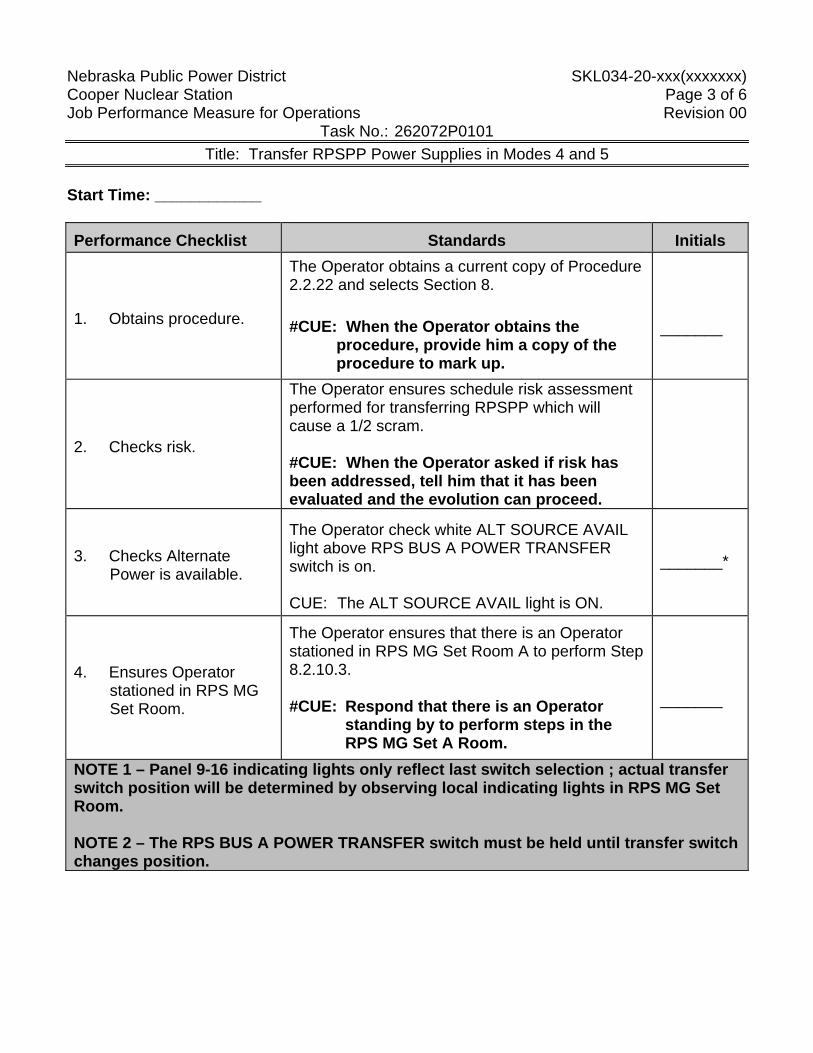
Nebraska Public Power District SKL034-20-xxx(xxxxxxx) Cooper Nuclear Station Page 3 of 6 Job Performance Measure for Operations Revision 00
Task No.: 262072P0101 Title: Transfer RPSPP Power Supplies in Modes 4 and 5
Start Time: ____________
Performance Checklist Standards Initials
1. Obtains procedure.
The Operator obtains a current copy of Procedure 2.2.22 and selects Section 8. #CUE: When the Operator obtains the
procedure, provide him a copy of the procedure to mark up.
_______
2. Checks risk.
The Operator ensures schedule risk assessment performed for transferring RPSPP which will cause a 1/2 scram. #CUE: When the Operator asked if risk has been addressed, tell him that it has been evaluated and the evolution can proceed.
3. Checks Alternate Power is available.
The Operator check white ALT SOURCE AVAIL light above RPS BUS A POWER TRANSFER switch is on. CUE: The ALT SOURCE AVAIL light is ON.
_______*
4. Ensures Operator stationed in RPS MG Set Room.
The Operator ensures that there is an Operator stationed in RPS MG Set Room A to perform Step 8.2.10.3. #CUE: Respond that there is an Operator
standing by to perform steps in the RPS MG Set A Room.
_______
NOTE 1 – Panel 9-16 indicating lights only reflect last switch selection ; actual transfer switch position will be determined by observing local indicating lights in RPS MG Set Room. NOTE 2 – The RPS BUS A POWER TRANSFER switch must be held until transfer switch changes position.
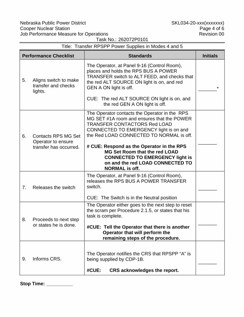
Nebraska Public Power District SKL034-20-xxx(xxxxxxx) Cooper Nuclear Station Page 4 of 6 Job Performance Measure for Operations Revision 00
Task No.: 262072P0101 Title: Transfer RPSPP Power Supplies in Modes 4 and 5
Performance Checklist Standards Initials
5. Aligns switch to make transfer and checks lights.
The Operator, at Panel 9-16 (Control Room), places and holds the RPS BUS A POWER TRANSFER switch to ALT FEED, and checks that the red ALT SOURCE ON light is on, and red GEN A ON light is off. CUE: The red ALT SOURCE ON light is on, and
the red GEN A ON light is off.
_______*
6. Contacts RPS MG Set Operator to ensure transfer has occurred.
The Operator contacts the Operator in the RPS MG SET #1A room and ensures that the POWER TRANSFER CONTACTORS Red LOAD CONNECTED TO EMERGENCY light is on and the Red LOAD CONNECTED TO NORMAL is off. # CUE: Respond as the Operator in the RPS
MG Set Room that the red LOAD CONNECTED TO EMERGENCY light is on and the red LOAD CONNECTED TO NORMAL is off.
_______
7. Releases the switch
The Operator, at Panel 9-16 (Control Room), releases the RPS BUS A POWER TRANSFER switch. CUE: The Switch is in the Neutral position
_______
8. Proceeds to next step or states he is done.
The Operator either goes to the next step to reset the scram per Procedure 2.1.5, or states that his task is complete. #CUE: Tell the Operator that there is another
Operator that will perform the remaining steps of the procedure.
_______
9. Informs CRS.
The Operator notifies the CRS that RPSPP “A” is being supplied by CDP-1B. #CUE: CRS acknowledges the report.
_______
Stop Time: __________
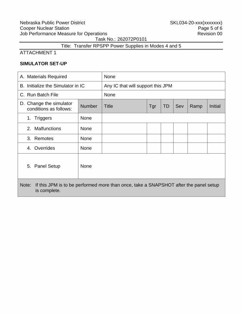
Nebraska Public Power District SKL034-20-xxx(xxxxxxx) Cooper Nuclear Station Page 5 of 6 Job Performance Measure for Operations Revision 00
Task No.: 262072P0101 Title: Transfer RPSPP Power Supplies in Modes 4 and 5
ATTACHMENT 1 SIMULATOR SET-UP A. Materials Required None
B. Initialize the Simulator in IC Any IC that will support this JPM
C. Run Batch File None
D. Change the simulator conditions as follows: Number Title Tgr TD Sev Ramp Initial
1. Triggers None
2. Malfunctions None
3. Remotes None
4. Overrides None
5. Panel Setup None
Note: If this JPM is to be performed more than once, take a SNAPSHOT after the panel setup is complete.
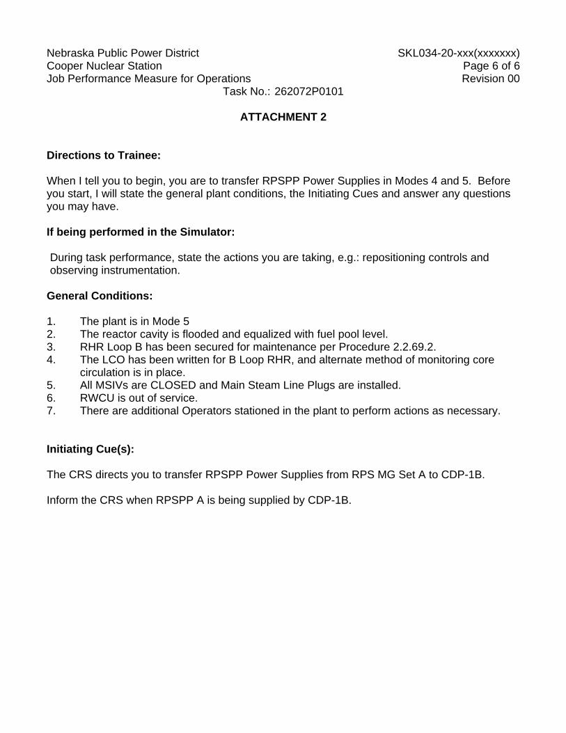
Nebraska Public Power District SKL034-20-xxx(xxxxxxx) Cooper Nuclear Station Page 6 of 6 Job Performance Measure for Operations Revision 00
Task No.: 262072P0101
ATTACHMENT 2 Directions to Trainee: When I tell you to begin, you are to transfer RPSPP Power Supplies in Modes 4 and 5. Before you start, I will state the general plant conditions, the Initiating Cues and answer any questions you may have. If being performed in the Simulator: During task performance, state the actions you are taking, e.g.: repositioning controls and observing instrumentation.
General Conditions: 1. The plant is in Mode 5 2. The reactor cavity is flooded and equalized with fuel pool level. 3. RHR Loop B has been secured for maintenance per Procedure 2.2.69.2. 4. The LCO has been written for B Loop RHR, and alternate method of monitoring core
circulation is in place. 5. All MSIVs are CLOSED and Main Steam Line Plugs are installed. 6. RWCU is out of service. 7. There are additional Operators stationed in the plant to perform actions as necessary.
Initiating Cue(s): The CRS directs you to transfer RPSPP Power Supplies from RPS MG Set A to CDP-1B. Inform the CRS when RPSPP A is being supplied by CDP-1B.
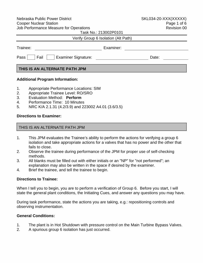
Nebraska Public Power District SKL034-20-XXX(XXXXX) Cooper Nuclear Station Page 1 of 6 Job Performance Measure for Operations Revision 00
Task No.: 213002P0101 Verify Group 6 Isolation (Alt Path)
Trainee: Examiner: Pass Fail Examiner Signature: Date: THIS IS AN ALTERNATE PATH JPM
Additional Program Information: 1. Appropriate Performance Locations: SIM 2. Appropriate Trainee Level: RO/SRO 3. Evaluation Method: Perform 4. Performance Time: 10 Minutes 5. NRC K/A 2.1.31 (4.2/3.9) and 223002 A4.01 (3.6/3.5) Directions to Examiner: THIS IS AN ALTERNATE PATH JPM
1. This JPM evaluates the Trainee’s ability to perform the actions for verifying a group 6
isolation and take appropriate actions for a valves that has no power and the other that fails to close.
2. Observe the trainee during performance of the JPM for proper use of self-checking methods.
3. All blanks must be filled out with either initials or an "NP" for "not performed"; an explanation may also be written in the space if desired by the examiner.
4. Brief the trainee, and tell the trainee to begin. Directions to Trainee: When I tell you to begin, you are to perform a verification of Group 6. Before you start, I will state the general plant conditions, the Initiating Cues, and answer any questions you may have. During task performance, state the actions you are taking, e.g.: repositioning controls and observing instrumentation. General Conditions: 1. The plant is in Hot Shutdown with pressure control on the Main Turbine Bypass Valves. 2. A spurious group 6 isolation has just occurred.
Nebraska Public Power District SKL034-20-XXX(XXXXX) Cooper Nuclear Station Page 2 of 6 Job Performance Measure for Operations Revision 00
Task No.: 213002P0101 Verify Group 6 Isolation (Alt Path)
General References: 1. 2.1.22, Recovering from a Group Isolation General Tools and Equipment: 1. None Special Conditions, References, Tools, Equipment: 1. Critical checks denoted by "*". 2. Simulator Setup: See Attachment 1 3. Alternate Path steps denoted by ♦ Task Standards: 1. 100% of critical elements successfully completed without error. 2. 100% of safety and radiological work practices. Initiating Cue(s): The plant has just scrammed and the CRS has directed you to perform the actions associated with verifying the Group 6 Isolation using the Hard Card and notify the CRS when you have completed the required actions. Note: Tell the trainee to begin.
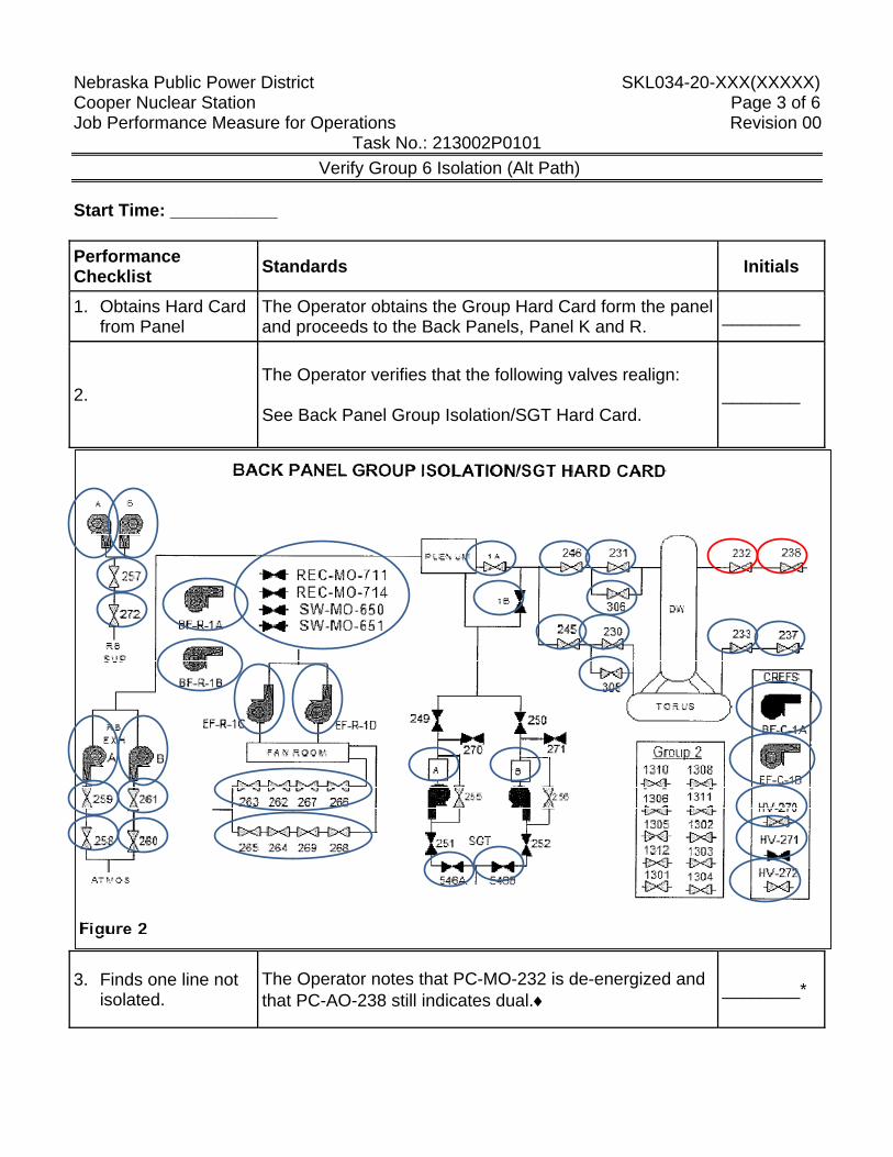
Nebraska Public Power District SKL034-20-XXX(XXXXX) Cooper Nuclear Station Page 3 of 6 Job Performance Measure for Operations Revision 00
Task No.: 213002P0101 Verify Group 6 Isolation (Alt Path)
Start Time: ___________ Performance Checklist Standards Initials
1. Obtains Hard Card from Panel
The Operator obtains the Group Hard Card form the panel and proceeds to the Back Panels, Panel K and R. ________
2. The Operator verifies that the following valves realign: See Back Panel Group Isolation/SGT Hard Card.
________
3. Finds one line not isolated.
The Operator notes that PC-MO-232 is de-energized and that PC-AO-238 still indicates dual.♦ ________*
Nebraska Public Power District SKL034-20-XXX(XXXXX) Cooper Nuclear Station Page 4 of 6 Job Performance Measure for Operations Revision 00
Task No.: 213002P0101 Verify Group 6 Isolation (Alt Path)
4. Attempts to isolate the line.
The Operator places the control switch for PC-AO-238 to the closed position on panel R. ________
5. Notifies CRS.
The Operator notifies the Shift Manager that Group 6 has been verified, but the Drywell Inlet Line cannot be verified closed, the 232 is de-energized and the 238 indicates dual indication. CUE: As the CRS respond to the report.
________
Stop Time: _________
Nebraska Public Power District SKL034-20-XXX(XXXXX) Cooper Nuclear Station Page 5 of 6 Job Performance Measure for Operations Revision 00
Task No.: 213002P0101 Verify Group 6 Isolation (Alt Path)
ATTACHMENT 1
SIMULATOR SET-UP A. Materials Required - None B. Initialize the simulator to any Mode 3 Operation at pressure IC. C. Change the simulator conditions as follows:
1. Triggers - None
2. Malfunctions None
3. Remotes - None
Instrument Tag Trigger TD Value Ramp 4. Overrides PC-MO-232 Red Light OFF PC-MO-232 Green Light OFF PC-AO-238 Red Light ON PC-AO-238 Green Light ON 5. Panel Setup
a. Ensure that there is a Group 6 in and that the overrides for the 232 and 238 are in.
Note: If this JPM is to be performed more than once, snap the simulator into an IC after the panel setup is complete.
Nebraska Public Power District SKL034-21-66 (15651) Cooper Nuclear Station Page 6 of 6 Job Performance Measure for Operations Revision 04
ATTACHMENT 2 Directions to Trainee: When I tell you to begin, you are to perform a verification of Group 6. Before you start, I will state the general plant conditions, the Initiating Cues, and answer any questions you may have. During task performance, state the actions you are taking, e.g.: repositioning controls and observing instrumentation. General Conditions: 1. The plant is in Hot Shutdown with pressure control on the Main Turbine Bypass Valves. 2. A spurious group 6 isolation has just occurred. Initiating Cue(s): The plant has just scrammed and the CRS has directed you to perform the actions associated with verifying the Group 6 Isolation using the Hard Card and notify the CRS when you have completed the required actions.
Nebraska Public Power District SKL034-10-106(42101) Cooper Nuclear Station Page 1 of 5 Job Performance Measure for Operations Revision 00
Task No: 26400700104
Task Title: Emergency Shutdown a Diesel Generator (Alternate Path)
Trainee: Examiner: Pass Fail Examiner Signature: Date: Additional Program Information:
ALTERNATE PATH JPM 1. Appropriate Performance Locations: Plant 2. Appropriate Trainee Level: SO / RO / SRO 3. Evaluation Method: Simulate 4. Performance Time: 5 minutes 5. NRC K/A 264000; A2.08 (3.3/3.7), A4.04 (3.7/3.7)
NOTE: THIS IS AN ALTERNATE PATH JPM. Normal Methods of stopping the Diesel will not work.
Directions to Examiner: 1. This JPM evaluates the trainee's ability to emergency stop the Diesel Generator locally 2. All blanks must be filled out with either initials or an ANP@ for Anot performed@; an
explanation may also be written in the space, if desired, by the examiner. 3. Give the trainee his copy of the Directions to the Trainee (Attachment 1) when ready to
start the JPM. 4. Brief the trainee and tell the trainee to begin. Directions to Trainee: When I tell you to begin, you are to simulate local emergency shutdown of Diesel Generator #2. Before you start, I will state the general plant conditions, the Initiating Cues and answer any questions you may have. When simulating, physically point to any meters, gauges, recorders and controls you would be using. State the position of controls as you would have manipulated them in order to complete the assigned task. General Conditions: 1. Plant is operating at power. 2. Diesel Generator #2 is running to support post maintenance testing following a rebuild. 3. Emergency shutdown of the DG 2 is required due to unusually loud noises coming from
Nebraska Public Power District SKL034-10-106(42101) Cooper Nuclear Station Page 2 of 5 Job Performance Measure for Operations Revision 00
Task No: 26400700104
Task Title: Emergency Shutdown a Diesel Generator (Alternate Path)
the Diesel. 4. One (1) mechanic Bob Jones is in the DG2 Room investigating the noise. General References: 1. Operating Procedure 2.2.20 General Tools and Equipment: 1. None Special Conditions, References, Tools, Equipment: 1. Critical checks denoted by "*.@ Task Standards: 1. 100% of critical elements successfully completed without error. 2. 100% of safety and radiological work practices. Initiating Cue(s): The CRS directs you to go to #2 DG room and secure the #2 Diesel Generator.
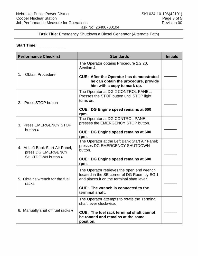
Nebraska Public Power District SKL034-10-106(42101) Cooper Nuclear Station Page 3 of 5 Job Performance Measure for Operations Revision 00
Task No: 26400700104
Task Title: Emergency Shutdown a Diesel Generator (Alternate Path)
Start Time: ____________ Performance Checklist
Standards Initials
1. Obtain Procedure
The Operator obtains Procedure 2.2.20, Section 4. CUE: After the Operator has demonstrated
he can obtain the procedure, provide him with a copy to mark up.
______
2. Press STOP button
The Operator at DG 2 CONTROL PANEL; Presses the STOP button until STOP light turns on. CUE: DG Engine speed remains at 600 rpm.
______
3. Press EMERGENCY STOP button ♦
The Operator at DG CONTROL PANEL; presses the EMERGENCY STOP button. CUE: DG Engine speed remains at 600 rpm.
______
4. At Left Bank Start Air Panel, press DG EMERGENCY SHUTDOWN button ♦
The Operator at the Left Bank Start Air Panel; presses DG EMERGENCY SHUTDOWN button. CUE: DG Engine speed remains at 600 rpm.
______
5. Obtains wrench for the fuel racks.
The Operator retrieves the open end wrench located in the SE corner of DG Room by EG 1 and places it on the terminal shaft lever. CUE: The wrench is connected to the terminal shaft.
______
6. Manually shut off fuel racks.♦
The Operator attempts to rotate the Terminal shaft lever clockwise. CUE: The fuel rack terminal shaft cannot be rotated and remains at the same position.
______
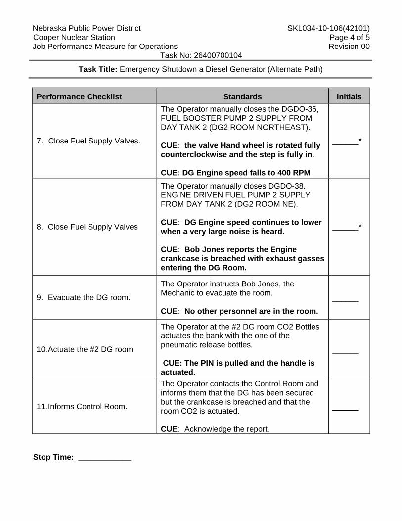
Nebraska Public Power District SKL034-10-106(42101) Cooper Nuclear Station Page 4 of 5 Job Performance Measure for Operations Revision 00
Task No: 26400700104
Task Title: Emergency Shutdown a Diesel Generator (Alternate Path)
Performance Checklist
Standards Initials
7. Close Fuel Supply Valves.
The Operator manually closes the DGDO-36, FUEL BOOSTER PUMP 2 SUPPLY FROM DAY TANK 2 (DG2 ROOM NORTHEAST). CUE: the valve Hand wheel is rotated fully counterclockwise and the step is fully in. CUE: DG Engine speed falls to 400 RPM
______*
8. Close Fuel Supply Valves
The Operator manually closes DGDO-38, ENGINE DRIVEN FUEL PUMP 2 SUPPLY FROM DAY TANK 2 (DG2 ROOM NE). CUE: DG Engine speed continues to lower when a very large noise is heard. CUE: Bob Jones reports the Engine crankcase is breached with exhaust gasses entering the DG Room.
_____ *
9. Evacuate the DG room.
The Operator instructs Bob Jones, the Mechanic to evacuate the room. CUE: No other personnel are in the room.
______
10. Actuate the #2 DG room
The Operator at the #2 DG room CO2 Bottles actuates the bank with the one of the pneumatic release bottles. CUE: The PIN is pulled and the handle is actuated.
______
11. Informs Control Room.
The Operator contacts the Control Room and informs them that the DG has been secured but the crankcase is breached and that the room CO2 is actuated. CUE: Acknowledge the report.
______
Stop Time: ____________
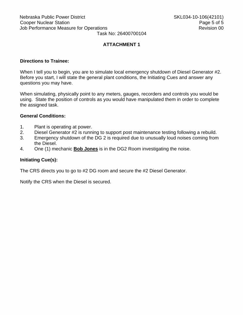
Nebraska Public Power District SKL034-10-106(42101) Cooper Nuclear Station Page 5 of 5 Job Performance Measure for Operations Revision 00
Task No: 26400700104
ATTACHMENT 1 Directions to Trainee: When I tell you to begin, you are to simulate local emergency shutdown of Diesel Generator #2. Before you start, I will state the general plant conditions, the Initiating Cues and answer any questions you may have. When simulating, physically point to any meters, gauges, recorders and controls you would be using. State the position of controls as you would have manipulated them in order to complete the assigned task. General Conditions: 1. Plant is operating at power. 2. Diesel Generator #2 is running to support post maintenance testing following a rebuild. 3. Emergency shutdown of the DG 2 is required due to unusually loud noises coming from
the Diesel. 4. One (1) mechanic Bob Jones is in the DG2 Room investigating the noise. Initiating Cue(s): The CRS directs you to go to #2 DG room and secure the #2 Diesel Generator. Notify the CRS when the Diesel is secured.
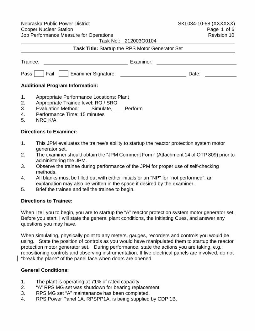
Nebraska Public Power District SKL034-10-58 (XXXXXX) Cooper Nuclear Station Page 1 of 6 Job Performance Measure for Operations Revision 10 Task No.: 212003O0104
Task Title: Startup the RPS Motor Generator Set Trainee: Examiner: Pass Fail Examiner Signature: Date: Additional Program Information: 1. Appropriate Performance Locations: Plant 2. Appropriate Trainee level: RO / SRO 3. Evaluation Method: ____Simulate, ____Perform 4. Performance Time: 15 minutes 5. NRC K/A Directions to Examiner: 1. This JPM evaluates the trainee's ability to startup the reactor protection system motor
generator set. 2. The examiner should obtain the “JPM Comment Form” (Attachment 14 of OTP 809) prior to
administering the JPM. 3. Observe the trainee during performance of the JPM for proper use of self-checking
methods. 4. All blanks must be filled out with either initials or an "NP" for "not performed"; an
explanation may also be written in the space if desired by the examiner. 5. Brief the trainee and tell the trainee to begin.
Directions to Trainee: When I tell you to begin, you are to startup the “A” reactor protection system motor generator set. Before you start, I will state the general plant conditions, the Initiating Cues, and answer any questions you may have. When simulating, physically point to any meters, gauges, recorders and controls you would be using. State the position of controls as you would have manipulated them to startup the reactor protection motor generator set. During performance, state the actions you are taking, e.g.: repositioning controls and observing instrumentation. If live electrical panels are involved, do not “break the plane” of the panel face when doors are opened. General Conditions: 1. The plant is operating at 71% of rated capacity. 2. “A” RPS MG set was shutdown for bearing replacement. 3. RPS MG set “A” maintenance has been completed. 4. RPS Power Panel 1A, RPSPP1A, is being supplied by CDP 1B.
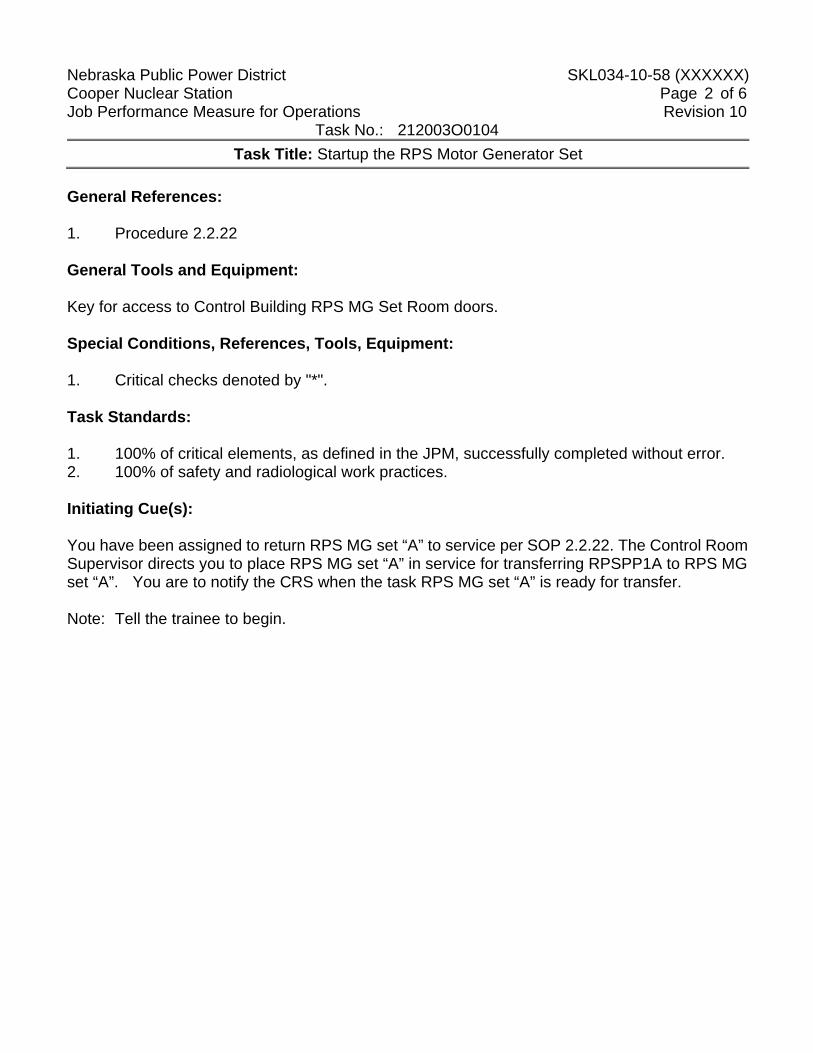
Nebraska Public Power District SKL034-10-58 (XXXXXX) Cooper Nuclear Station Page 2 of 6 Job Performance Measure for Operations Revision 10 Task No.: 212003O0104
Task Title: Startup the RPS Motor Generator Set General References: 1. Procedure 2.2.22 General Tools and Equipment: Key for access to Control Building RPS MG Set Room doors. Special Conditions, References, Tools, Equipment: 1. Critical checks denoted by "*". Task Standards: 1. 100% of critical elements, as defined in the JPM, successfully completed without error. 2. 100% of safety and radiological work practices. Initiating Cue(s): You have been assigned to return RPS MG set “A” to service per SOP 2.2.22. The Control Room Supervisor directs you to place RPS MG set “A” in service for transferring RPSPP1A to RPS MG set “A”. You are to notify the CRS when the task RPS MG set “A” is ready for transfer. Note: Tell the trainee to begin.
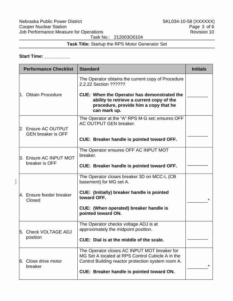
Nebraska Public Power District SKL034-10-58 (XXXXXX) Cooper Nuclear Station Page 3 of 6 Job Performance Measure for Operations Revision 10 Task No.: 212003O0104
Task Title: Startup the RPS Motor Generator Set Start Time: __________
Performance Checklist Standard Initials
1. Obtain Procedure
The Operator obtains the current copy of Procedure 2.2.22 Section ?????? CUE: When the Operator has demonstrated the
ability to retrieve a current copy of the procedure, provide him a copy that he can mark up.
________
2. Ensure AC OUTPUT GEN breaker is OFF
The Operator at the “A” RPS M-G set; ensures OFF AC OUTPUT GEN breaker. CUE: Breaker handle is pointed toward OFF.
________
3. Ensure AC INPUT MOT breaker is OFF
The Operator ensures OFF AC INPUT MOT breaker. CUE: Breaker handle is pointed toward OFF.
________
4. Ensure feeder breaker Closed
The Operator closes breaker 3D on MCC-L (CB basement) for MG set A. CUE: (Initially) breaker handle is pointed toward OFF. CUE: (When operated) breaker handle is pointed toward ON.
________*
5. Check VOLTAGE ADJ position
The Operator checks voltage ADJ is at approximately the midpoint position. CUE: Dial is at the middle of the scale.
________
6. Close drive motor breaker
The Operator closes AC INPUT MOT breaker for MG Set A located at RPS Control Cubicle A in the Control Building reactor protection system room A. CUE: Breaker handle is pointed toward ON.
________*
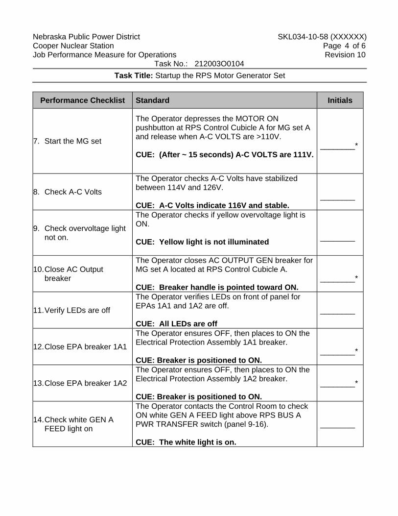
Nebraska Public Power District SKL034-10-58 (XXXXXX) Cooper Nuclear Station Page 4 of 6 Job Performance Measure for Operations Revision 10 Task No.: 212003O0104
Task Title: Startup the RPS Motor Generator Set
Performance Checklist Standard Initials
7. Start the MG set
The Operator depresses the MOTOR ON pushbutton at RPS Control Cubicle A for MG set A and release when A-C VOLTS are >110V. CUE: (After ~ 15 seconds) A-C VOLTS are 111V.
________*
8. Check A-C Volts
The Operator checks A-C Volts have stabilized between 114V and 126V. CUE: A-C Volts indicate 116V and stable.
________
9. Check overvoltage light not on.
The Operator checks if yellow overvoltage light is ON. CUE: Yellow light is not illuminated
________
10. Close AC Output breaker
The Operator closes AC OUTPUT GEN breaker for MG set A located at RPS Control Cubicle A. CUE: Breaker handle is pointed toward ON.
________*
11. Verify LEDs are off
The Operator verifies LEDs on front of panel for EPAs 1A1 and 1A2 are off. CUE: All LEDs are off
________
12. Close EPA breaker 1A1
The Operator ensures OFF, then places to ON the Electrical Protection Assembly 1A1 breaker. CUE: Breaker is positioned to ON.
________*
13. Close EPA breaker 1A2
The Operator ensures OFF, then places to ON the Electrical Protection Assembly 1A2 breaker. CUE: Breaker is positioned to ON.
________*
14. Check white GEN A FEED light on
The Operator contacts the Control Room to check ON white GEN A FEED light above RPS BUS A PWR TRANSFER switch (panel 9-16). CUE: The white light is on.
________
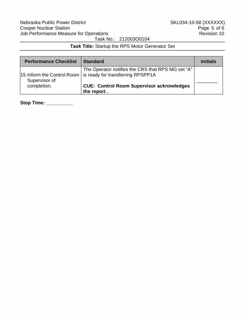
Nebraska Public Power District SKL034-10-58 (XXXXXX) Cooper Nuclear Station Page 5 of 6 Job Performance Measure for Operations Revision 10 Task No.: 212003O0104
Task Title: Startup the RPS Motor Generator Set
Performance Checklist Standard Initials
15. Inform the Control Room Supervisor of completion.
The Operator notifies the CRS that RPS MG set “A” is ready for transferring RPSPP1A CUE: Control Room Supervisor acknowledges the report .
________
Stop Time: __________
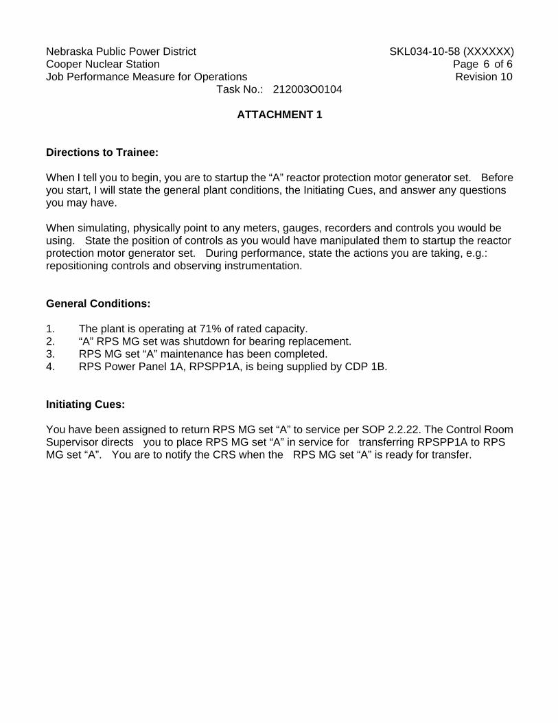
Nebraska Public Power District SKL034-10-58 (XXXXXX) Cooper Nuclear Station Page 6 of 6 Job Performance Measure for Operations Revision 10 Task No.: 212003O0104
ATTACHMENT 1 Directions to Trainee: When I tell you to begin, you are to startup the “A” reactor protection motor generator set. Before you start, I will state the general plant conditions, the Initiating Cues, and answer any questions you may have. When simulating, physically point to any meters, gauges, recorders and controls you would be using. State the position of controls as you would have manipulated them to startup the reactor protection motor generator set. During performance, state the actions you are taking, e.g.: repositioning controls and observing instrumentation. General Conditions: 1. The plant is operating at 71% of rated capacity. 2. “A” RPS MG set was shutdown for bearing replacement. 3. RPS MG set “A” maintenance has been completed. 4. RPS Power Panel 1A, RPSPP1A, is being supplied by CDP 1B. Initiating Cues: You have been assigned to return RPS MG set “A” to service per SOP 2.2.22. The Control Room Supervisor directs you to place RPS MG set “A” in service for transferring RPSPP1A to RPS MG set “A”. You are to notify the CRS when the RPS MG set “A” is ready for transfer.
Nebraska Public Power District SKL034-10-85 (2100) Cooper Nuclear Station Page 1 of 6 Job Performance Measure for Operations Revision 05
Task No.: 200027O0401
Place Standby CRD Flow Control Valve A In Service When In Service Valve Fails Closed
Trainee: Examiner: Pass Fail Examiner Signature: Date: Additional Program Information: 1. Appropriate Performance Locations: Plant 2. Appropriate Trainee Level: SO / RO / SRO 3. Evaluation Method: Simulate 4. Performance Time: 15 minutes 5. NRC K/A: 201003 A2.06 (3.0/3.1)
Directions to Examiner: 1. This JPM evaluated the examinee's ability to place the standby CRD flow control valve
in-service when the in-service valve fails closed. 2. All blanks must be filled out with either initials or an ANP@ for Anot performed@; an
explanation may also be written in the space, if desired, by the examiner. 3. Give the trainee his copy of the Directions to the Trainee (Attachment 1) when ready to
start the JPM. 4. Brief the trainee and tell the trainee to begin. Directions to Trainee: When I tell you to begin, you are to place the standby CRD flow control valve A in-service when the in-service valve failed Closed. Before you start, I will state the general plant conditions, the Initiating Cues, and answer any questions you may have. When simulating, physically point to any meters, gauges, recorders and controls you would be using. State the position of controls as you would have manipulated them in order to complete the assigned task. General Conditions: 1. The in-service FCV is indicating full closed in the Control Room. 2. Attempts to maintain cooling water flow at 50 gpm by operating CRD-FC-301 in manual
have not been successful. 3. Drive water d/p is indicating at the bottom of the scale and cooling water flow is indicating
low in the Control Room.
Nebraska Public Power District SKL034-10-85 (2100) Cooper Nuclear Station Page 2 of 6 Job Performance Measure for Operations Revision 05
Task No.: 200027O0401
Place Standby CRD Flow Control Valve A In Service When In Service Valve Fails Closed
General References: 1. Abnormal Procedure 2.4CRD 2. 2.2.8 General Tools and Equipment: 1. None Special Conditions, References, Tools, Equipment: 1. Critical checks denoted by "*". Task Standards: 1. 100% of critical elements successfully completed without error. 2. 100% of safety and radiological work practices. Initiating Cue(s): The Control Room Supervisor directs you to perform the Reactor Building actions to place the standby CRD flow control valve AA@ in-service with the in-service CRD flow control valve failed closed. Notify the CRS when the task is complete.
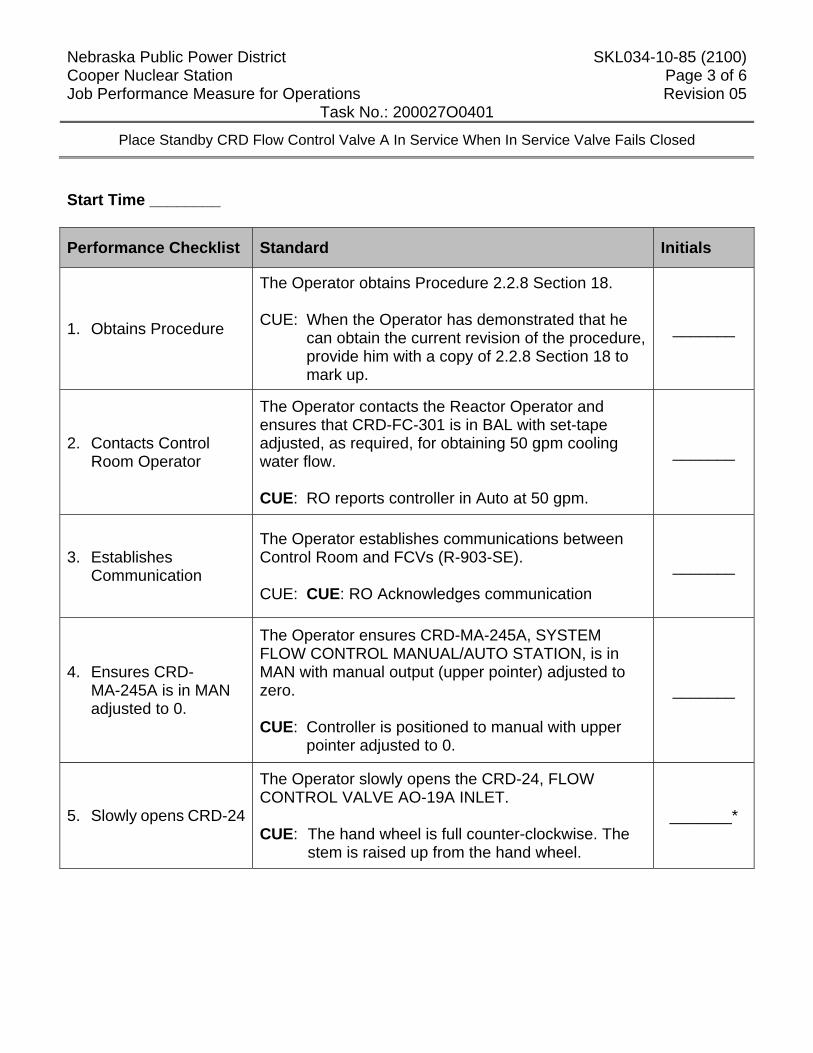
Nebraska Public Power District SKL034-10-85 (2100) Cooper Nuclear Station Page 3 of 6 Job Performance Measure for Operations Revision 05
Task No.: 200027O0401
Place Standby CRD Flow Control Valve A In Service When In Service Valve Fails Closed
Start Time ________
Performance Checklist Standard Initials
1. Obtains Procedure
The Operator obtains Procedure 2.2.8 Section 18. CUE: When the Operator has demonstrated that he
can obtain the current revision of the procedure, provide him with a copy of 2.2.8 Section 18 to mark up.
_______
2. Contacts Control Room Operator
The Operator contacts the Reactor Operator and ensures that CRD-FC-301 is in BAL with set-tape adjusted, as required, for obtaining 50 gpm cooling water flow. CUE: RO reports controller in Auto at 50 gpm.
_______
3. Establishes Communication
The Operator establishes communications between Control Room and FCVs (R-903-SE). CUE: CUE: RO Acknowledges communication
_______
4. Ensures CRD- MA-245A is in MAN adjusted to 0.
The Operator ensures CRD-MA-245A, SYSTEM FLOW CONTROL MANUAL/AUTO STATION, is in MAN with manual output (upper pointer) adjusted to zero. CUE: Controller is positioned to manual with upper
pointer adjusted to 0.
_______
5. Slowly opens CRD-24
The Operator slowly opens the CRD-24, FLOW CONTROL VALVE AO-19A INLET. CUE: The hand wheel is full counter-clockwise. The
stem is raised up from the hand wheel.
_______*
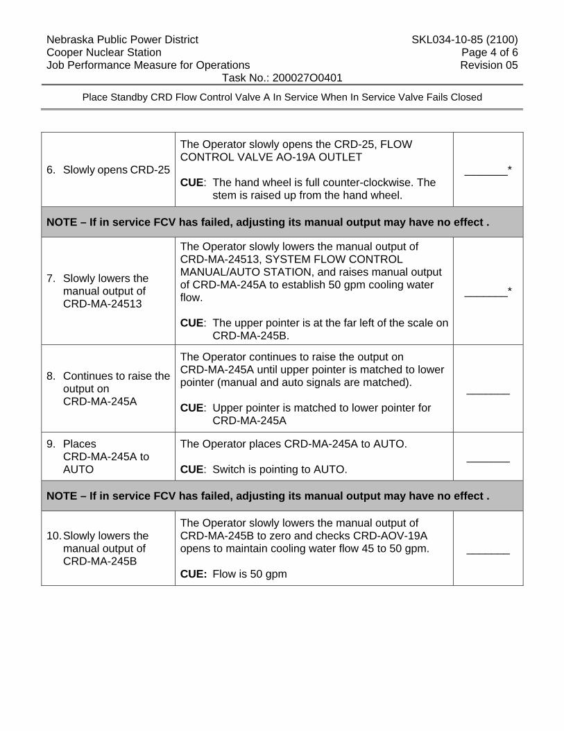
Nebraska Public Power District SKL034-10-85 (2100) Cooper Nuclear Station Page 4 of 6 Job Performance Measure for Operations Revision 05
Task No.: 200027O0401
Place Standby CRD Flow Control Valve A In Service When In Service Valve Fails Closed
6. Slowly opens CRD-25
The Operator slowly opens the CRD-25, FLOW CONTROL VALVE AO-19A OUTLET CUE: The hand wheel is full counter-clockwise. The
stem is raised up from the hand wheel.
_______*
NOTE – If in service FCV has failed, adjusting its manual output may have no effect .
7. Slowly lowers the manual output of CRD-MA-24513
The Operator slowly lowers the manual output of CRD-MA-24513, SYSTEM FLOW CONTROL MANUAL/AUTO STATION, and raises manual output of CRD-MA-245A to establish 50 gpm cooling water flow. CUE: The upper pointer is at the far left of the scale on
CRD-MA-245B.
_______*
8. Continues to raise the output on CRD-MA-245A
The Operator continues to raise the output on CRD-MA-245A until upper pointer is matched to lower pointer (manual and auto signals are matched). CUE: Upper pointer is matched to lower pointer for
CRD-MA-245A
_______
9. Places CRD-MA-245A to AUTO
The Operator places CRD-MA-245A to AUTO. CUE: Switch is pointing to AUTO.
_______
NOTE – If in service FCV has failed, adjusting its manual output may have no effect .
10. Slowly lowers the manual output of CRD-MA-245B
The Operator slowly lowers the manual output of CRD-MA-245B to zero and checks CRD-AOV-19A opens to maintain cooling water flow 45 to 50 gpm. CUE: Flow is 50 gpm
_______
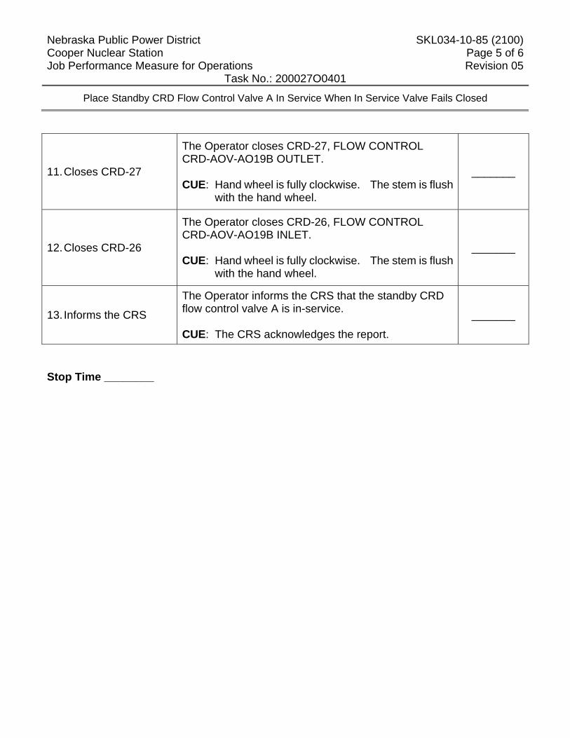
Nebraska Public Power District SKL034-10-85 (2100) Cooper Nuclear Station Page 5 of 6 Job Performance Measure for Operations Revision 05
Task No.: 200027O0401
Place Standby CRD Flow Control Valve A In Service When In Service Valve Fails Closed
11. Closes CRD-27
The Operator closes CRD-27, FLOW CONTROL CRD-AOV-AO19B OUTLET. CUE: Hand wheel is fully clockwise. The stem is flush
with the hand wheel.
_______
12. Closes CRD-26
The Operator closes CRD-26, FLOW CONTROL CRD-AOV-AO19B INLET. CUE: Hand wheel is fully clockwise. The stem is flush
with the hand wheel.
_______
13. Informs the CRS
The Operator informs the CRS that the standby CRD flow control valve A is in-service. CUE: The CRS acknowledges the report.
_______
Stop Time ________
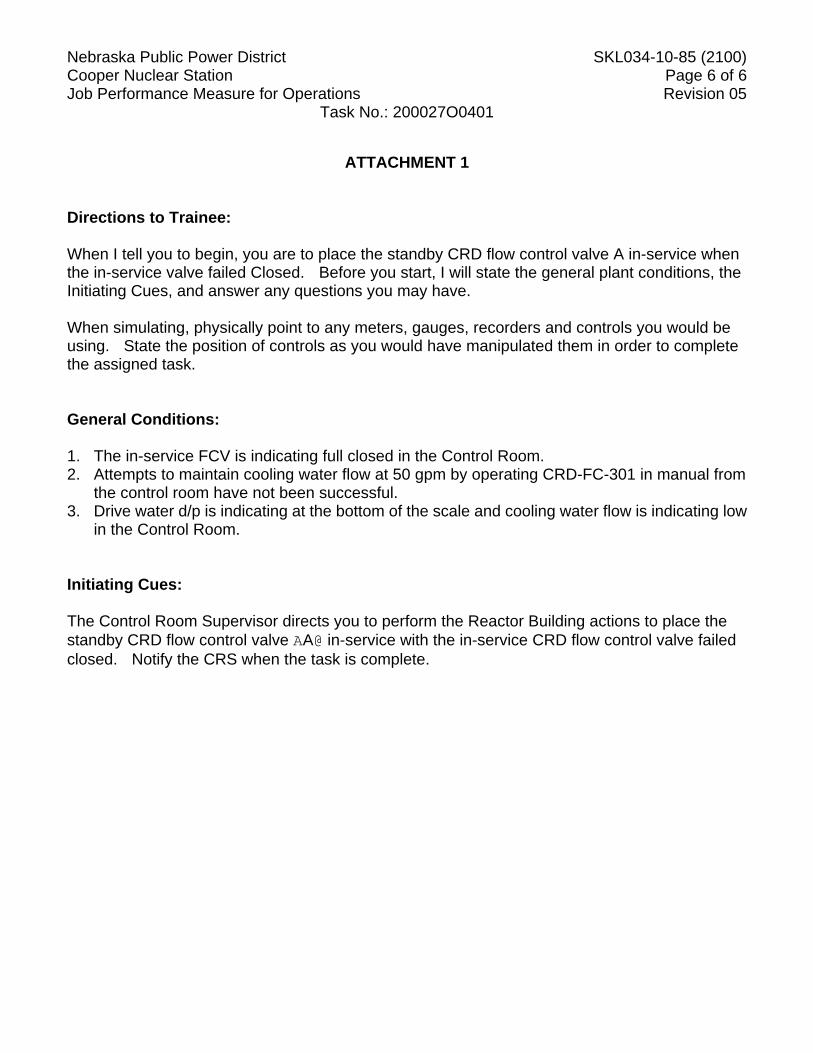
Nebraska Public Power District SKL034-10-85 (2100) Cooper Nuclear Station Page 6 of 6 Job Performance Measure for Operations Revision 05
Task No.: 200027O0401
ATTACHMENT 1 Directions to Trainee: When I tell you to begin, you are to place the standby CRD flow control valve A in-service when the in-service valve failed Closed. Before you start, I will state the general plant conditions, the Initiating Cues, and answer any questions you may have. When simulating, physically point to any meters, gauges, recorders and controls you would be using. State the position of controls as you would have manipulated them in order to complete the assigned task. General Conditions: 1. The in-service FCV is indicating full closed in the Control Room. 2. Attempts to maintain cooling water flow at 50 gpm by operating CRD-FC-301 in manual from
the control room have not been successful. 3. Drive water d/p is indicating at the bottom of the scale and cooling water flow is indicating low
in the Control Room. Initiating Cues: The Control Room Supervisor directs you to perform the Reactor Building actions to place the standby CRD flow control valve AA@ in-service with the in-service CRD flow control valve failed closed. Notify the CRS when the task is complete.
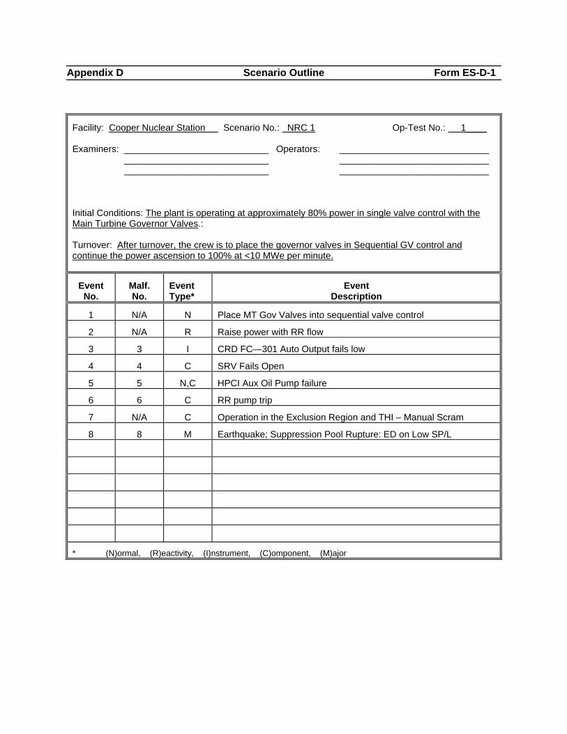
Appendix D Scenario Outline Form ES-D-1
Facility: Cooper Nuclear Station Scenario No.: NRC 1 Op-Test No.: 1____ Examiners: ____________________________ Operators: _____________________________
____________________________ _____________________________ ____________________________ _____________________________
Initial Conditions: The plant is operating at approximately 80% power in single valve control with the Main Turbine Governor Valves.: Turnover: After turnover, the crew is to place the governor valves in Sequential GV control and continue the power ascension to 100% at <10 MWe per minute.
Event No.
Malf. No.
Event Type*
Event Description
1 N/A N Place MT Gov Valves into sequential valve control
2 N/A R Raise power with RR flow
3 3 I CRD FC—301 Auto Output fails low
4 4 C SRV Fails Open
5 5 N,C HPCI Aux Oil Pump failure
6 6 C RR pump trip
7 N/A C Operation in the Exclusion Region and THI – Manual Scram
8 8 M Earthquake; Suppression Pool Rupture: ED on Low SP/L
* (N)ormal, (R)eactivity, (I)nstrument, (C)omponent, (M)ajor
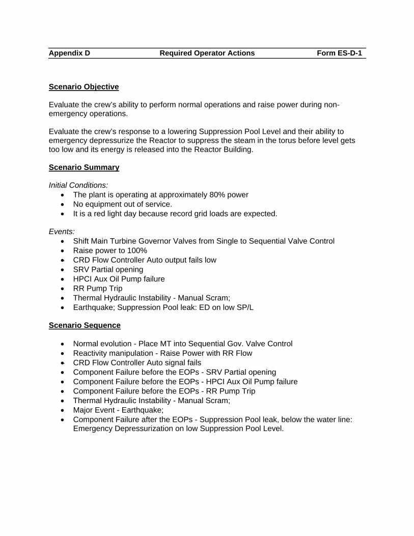
Appendix D Required Operator Actions Form ES-D-1
Scenario Objective Evaluate the crew’s ability to perform normal operations and raise power during non-emergency operations. Evaluate the crew’s response to a lowering Suppression Pool Level and their ability to emergency depressurize the Reactor to suppress the steam in the torus before level gets too low and its energy is released into the Reactor Building. Scenario Summary Initial Conditions:
• The plant is operating at approximately 80% power • No equipment out of service. • It is a red light day because record grid loads are expected.
Events:
• Shift Main Turbine Governor Valves from Single to Sequential Valve Control • Raise power to 100% • CRD Flow Controller Auto output fails low • SRV Partial opening • HPCI Aux Oil Pump failure • RR Pump Trip • Thermal Hydraulic Instability - Manual Scram; • Earthquake; Suppression Pool leak: ED on low SP/L
Scenario Sequence
• Normal evolution - Place MT into Sequential Gov. Valve Control • Reactivity manipulation - Raise Power with RR Flow • CRD Flow Controller Auto signal fails • Component Failure before the EOPs - SRV Partial opening • Component Failure before the EOPs - HPCI Aux Oil Pump failure • Component Failure before the EOPs - RR Pump Trip • Thermal Hydraulic Instability - Manual Scram; • Major Event - Earthquake; • Component Failure after the EOPs - Suppression Pool leak, below the water line:
Emergency Depressurization on low Suppression Pool Level.
Appendix D Required Operator Actions Form ES-D-1
Event One: Place MT Gov Valves into sequential valve control Malfunction Required: No malfunction required; this is a normal manipulation for the BOP. Objective: Evaluate the crew’s ability to select the Digital Electro Hydraulic Controller and perform the required manipulations on the touch screen to shift the main turbine valve governor control to a Sequential alignment. Success Path: The Operator, in accordance with Procedure 2.2.77.1, performs the steps necessary to make the Turbine Governor Valves transition smoothly from single valve control to sequential valve control which causes turbine efficiency improvement (MWatts increase). Event Two: Raise Power to 100% Malfunction Required: No malfunction required, this is a normal manipulation for the BOP. Objective: Evaluate the RO ability to adjust Reactor Recirculation Pump flows to make power increase from ~80% to ~100%, by alternately raising flow on one RR Pump, letting the plant respond then making a similar adjustment on the other pump’s controller. Success Path: Both Reactor Recirculation Pump’s speeds are raised from ~65 to ~80, maintaining them within the required 5% allowed by Tech Specs, and it is done in accordance with Procedure 2.1.10. Event Three: CRD FC-301 Auto Signal Failure Malfunction Required: Override 03A35A1 CRD-FC-301 CRD System Flow Control Setpoint set at 0%. Objective: Evaluate the crews response to CRD-FC-301 Automatic control signal failure resulting in high charging water pressure and low cooling water flow. Evaluate the RO’s ability to diagnose the controller has failed. Success Path: CRD-FC-301 placed in Manual and CRD system flows and pressures returned to normal. Event Four: SRV Fails Open
Appendix D Required Operator Actions Form ES-D-1
Malfunction Required: AD06b set at 50% to start the relief valve leaking then it is modified to 20% to minimize the heat addition to the torus. Objective: Evaluate the crew’s performance of Abnormal Procedure 2.4SRV for a leaking SRV which has the Operator cycle the leaking valve to reseat it. Evaluate the CRS addressing Technical Specification 3.6.2.1 for Suppression Pool Average Temperature, if the SRV is not closed within a short period of time. Success Path: The Operator notices and responds to the leaking SRV in accordance with Annunciator Procedures and 2.4SRV. The SRV will be cycled open then taken back to the closed position to reseat the valve. Once the valve has been cycled the tail pipe temperature starts lowering and the heat addition into the Torus is secured. The CRS determines that Technical Specification 3.6.2.1 for Suppression Pool Average Temperature applies or not. Event Five: HPCI Aux Oil Pump failure Malfunction Required: HP12 Active set at 100%, at the start of the scenario. This failure will not start until the HPCI Aux Oil Pump is started. Objective: Evaluate the crew’s response to an oil leak in the HPCI control oil system while performing the section of the Operating Procedure for the HPCI system 2.2.33 to start the Aux Oil Pump for maintenance. During this event the Operator will be required to secure the pump. Evaluate the CRS’s ability to determine that HPCI is Inoperable. Success Path: The HPCI system is declared Inoperable per TS 3.5.1. Condition “C” 14 day LCO. RCIC is checked to be operable within 1 hour and the Aux Oil Pump is secured to prevent operation. Event Six: RR Pump Trip Malfunction Required: RR05a Trip RR MG Set field breaker. Objective: Evaluate the crew’s response in accordance with Abnormal Procedure 2.4RR and determine Operation in the Exclusion Region of the Power to Flow Map. Evaluate the CRS addressing Tech Specs for operation in the stability exclusion region. Success Path:
Appendix D Required Operator Actions Form ES-D-1
The Operator determines the Recirc Pump tripped and enters Abnormal Procedure 2.4RR and notes operation in the Stability Exclusion Region of the Power to Flow Map and makes preparations to exit the region. CRS will declare the pump not in operation in accordance with Tech Specs 3.4.1 Condition “A”. Event Seven: Thermal Hydraulic Instability - Manual Scram Malfunction Required: CR04b Core Thermal Hydraulic Instability Out of Phase 20% IOR ZAIRRFCDEMD(2) = 60% to generate a runback on the other Recirc pump. Objective: Evaluate the crew’s recognition of abnormal neutron flux oscillations are occurring while operating in the Stability Exclusion Region and Scrams the reactor. Success Path: The Operator scrams the reactor, in accordance with 2.4RR when core thermal instability is noticed. Event Eight: Earthquake; Suppression Pool leak: ED on low SP/L Malfunction Required: HV02b Major Earthquake set to 25% PC08 Suppression Pool Water Leak 25% level lowers at -0.2”/min Objective: Evaluate the crew’s response to a major earthquake in accordance with Emergency Procedure 5.1Quake. Evaluate the crew’s ability to monitor and control the consequences of an Unisolable leak in the torus below the normal water level. Evaluate the crew’s ability to anticipate emergency depressurization and transfer as much energy to the condenser prior to emergency depressurizing the Reactor. Success Path: The crew emergency depressurizes the reactor when suppression pool level lowers to 9.6’. Scenario Termination: When the reactor is depressurized (50 psig above Torus pressure) and level is being maintained between +3” to +54” and the lead examiner has seen enough, the scenario may be stopped.
Appendix D Required Operator Actions Form ES-D-2
Op-Test No.: 1 Scenario No.: 1 Event No.: 1
When to initiate:
When the Crew has assumed the watch and at the direction of the lead examiner.
Event Description: Place MT Gov Valves into sequential valve control
Time Position Applicant’s Action or Behavior
CRS Direct BOP to transfer Main Turbine Governor valves to Sequential valve control per Procedure 2.2.77.1
BOP
Transfers Main Turbine Governor valves from Single into Sequential valve control per Procedure 2.2.77.1, Section 14: NOTE – Valve transfer takes ~ 3 minutes. 14.2.1 On open GOV VALVE SINGLE SEQ TRANSFER control on
the MODE 4 - TURBINE FOLLOW REACTOR MANUAL screen, perform following:
14.2.1.1 Press SEQ VALVE button. 14.2.1.2 Verify HOLD button backlights yellow.
NOTE – HOLD button may be pressed at any time to pause transfer. 14.2.1.3 Press GO button to start transfer. 14.2.1.4 When governor valves reach their sequential positions, verify GO button is not backlit.
14.2.2 Contact Reactor Engineering to change CPRLIM for sequential valve operation.
BOP Monitors MT Governor valves position and Main Generator output rise on HMI.
RO Monitors Reactor power and performs peer checks as requested.
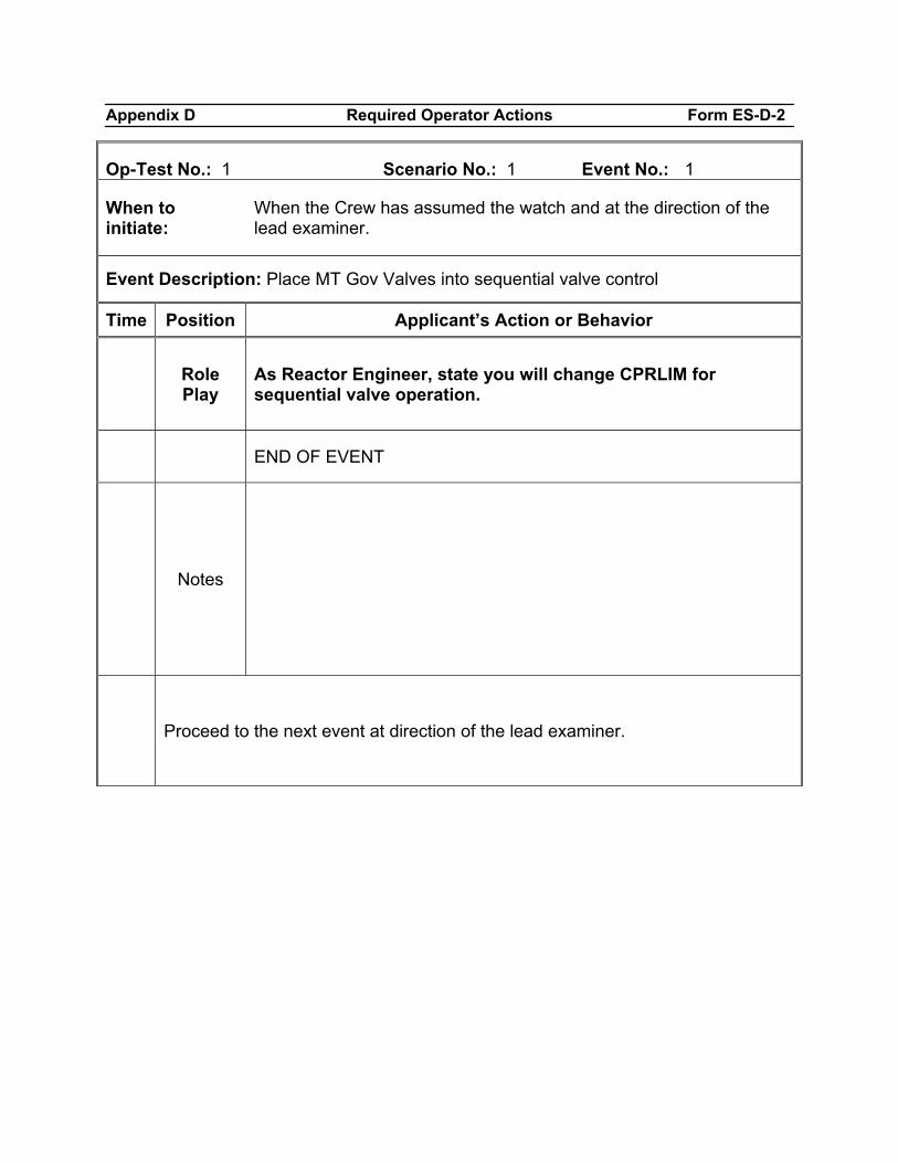
Appendix D Required Operator Actions Form ES-D-2
Op-Test No.: 1 Scenario No.: 1 Event No.: 1
When to initiate:
When the Crew has assumed the watch and at the direction of the lead examiner.
Event Description: Place MT Gov Valves into sequential valve control
Time Position Applicant’s Action or Behavior
Role Play
As Reactor Engineer, state you will change CPRLIM for sequential valve operation.
END OF EVENT
Notes
Proceed to the next event at direction of the lead examiner.
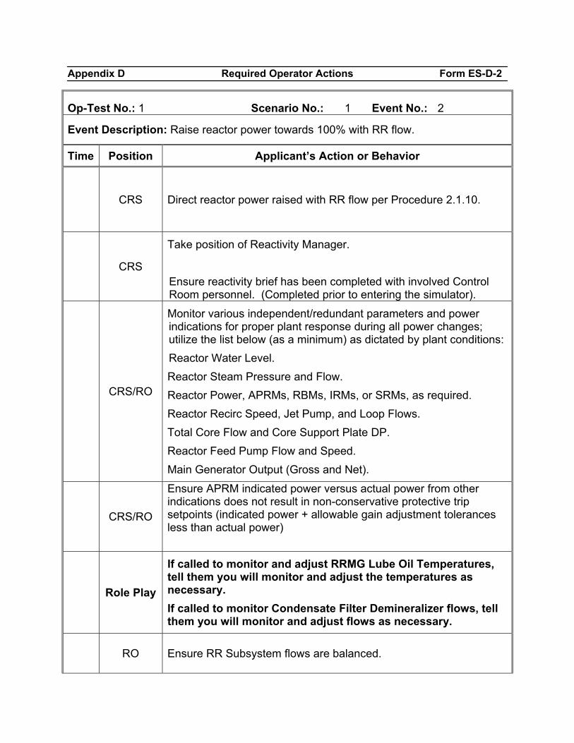
Appendix D Required Operator Actions Form ES-D-2
Op-Test No.: 1 Scenario No.: 1 Event No.: 2
Event Description: Raise reactor power towards 100% with RR flow.
Time Position Applicant’s Action or Behavior
CRS Direct reactor power raised with RR flow per Procedure 2.1.10.
CRS
Take position of Reactivity Manager. Ensure reactivity brief has been completed with involved Control Room personnel. (Completed prior to entering the simulator).
CRS/RO
Monitor various independent/redundant parameters and power indications for proper plant response during all power changes; utilize the list below (as a minimum) as dictated by plant conditions: Reactor Water Level. Reactor Steam Pressure and Flow. Reactor Power, APRMs, RBMs, IRMs, or SRMs, as required. Reactor Recirc Speed, Jet Pump, and Loop Flows. Total Core Flow and Core Support Plate DP. Reactor Feed Pump Flow and Speed. Main Generator Output (Gross and Net).
CRS/RO
Ensure APRM indicated power versus actual power from other indications does not result in non-conservative protective trip setpoints (indicated power + allowable gain adjustment tolerances less than actual power)
Role Play
If called to monitor and adjust RRMG Lube Oil Temperatures, tell them you will monitor and adjust the temperatures as necessary. If called to monitor Condensate Filter Demineralizer flows, tell them you will monitor and adjust flows as necessary.
RO Ensure RR Subsystem flows are balanced.
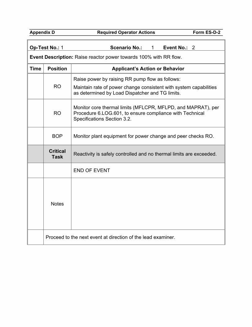
Appendix D Required Operator Actions Form ES-D-2
Op-Test No.: 1 Scenario No.: 1 Event No.: 2
Event Description: Raise reactor power towards 100% with RR flow.
Time Position Applicant’s Action or Behavior
RO
Raise power by raising RR pump flow as follows: Maintain rate of power change consistent with system capabilities as determined by Load Dispatcher and TG limits.
RO Monitor core thermal limits (MFLCPR, MFLPD, and MAPRAT), per Procedure 6.LOG.601, to ensure compliance with Technical Specifications Section 3.2.
BOP Monitor plant equipment for power change and peer checks RO.
Critical
Task Reactivity is safely controlled and no thermal limits are exceeded.
END OF EVENT
Notes
Proceed to the next event at direction of the lead examiner.
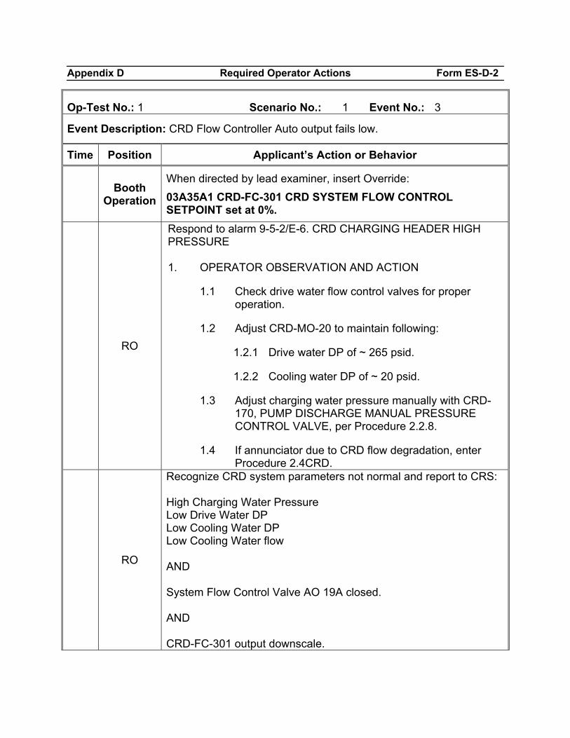
Appendix D Required Operator Actions Form ES-D-2
Op-Test No.: 1 Scenario No.: 1 Event No.: 3
Event Description: CRD Flow Controller Auto output fails low.
Time Position Applicant’s Action or Behavior
Booth Operation
When directed by lead examiner, insert Override: 03A35A1 CRD-FC-301 CRD SYSTEM FLOW CONTROL SETPOINT set at 0%.
RO
Respond to alarm 9-5-2/E-6. CRD CHARGING HEADER HIGH PRESSURE 1. OPERATOR OBSERVATION AND ACTION
1.1 Check drive water flow control valves for proper operation.
1.2 Adjust CRD-MO-20 to maintain following:
1.2.1 Drive water DP of ~ 265 psid.
1.2.2 Cooling water DP of ~ 20 psid.
1.3 Adjust charging water pressure manually with CRD-170, PUMP DISCHARGE MANUAL PRESSURE CONTROL VALVE, per Procedure 2.2.8.
1.4 If annunciator due to CRD flow degradation, enter Procedure 2.4CRD.
RO
Recognize CRD system parameters not normal and report to CRS: High Charging Water Pressure Low Drive Water DP Low Cooling Water DP Low Cooling Water flow AND System Flow Control Valve AO 19A closed. AND CRD-FC-301 output downscale.
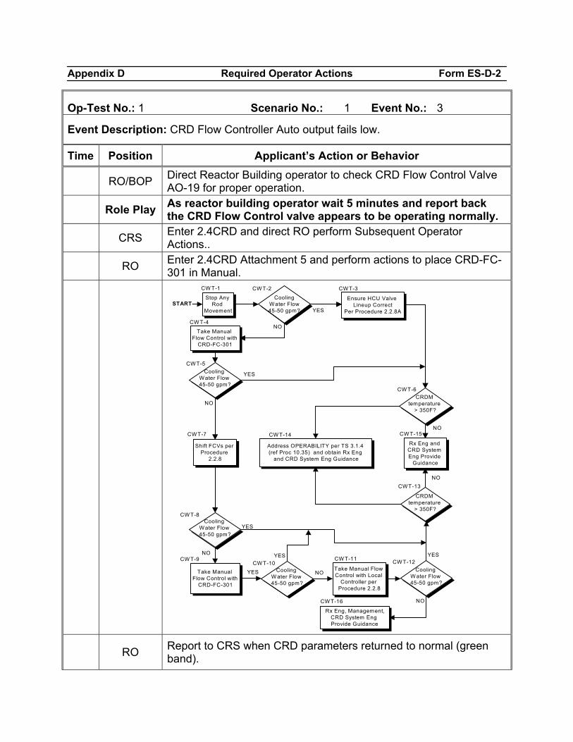
Appendix D Required Operator Actions Form ES-D-2
Op-Test No.: 1 Scenario No.: 1 Event No.: 3
Event Description: CRD Flow Controller Auto output fails low.
Time Position Applicant’s Action or Behavior
RO/BOP Direct Reactor Building operator to check CRD Flow Control Valve AO-19 for proper operation.
Role Play As reactor building operator wait 5 minutes and report back the CRD Flow Control valve appears to be operating normally.
CRS Enter 2.4CRD and direct RO perform Subsequent Operator Actions..
RO Enter 2.4CRD Attachment 5 and perform actions to place CRD-FC-301 in Manual.
Cooling Water Flow 45-50 gpm?
Take Manual Flow Control with
CRD-FC-301
Cooling Water Flow 45-50 gpm?
Shift FCVs per Procedure
2.2.8
Ensure HCU Valve Lineup Correct
Per Procedure 2.2.8A
Rx Eng and CRD System Eng Provide
Guidance
NO
YES
Stop Any Rod
Movement
NO
YES
Take Manual Flow Control with
CRD-FC-301
Cooling Water Flow 45-50 gpm?
Cooling W ater Flow 45-50 gpm?
Take Manual Flow Control with Local
Controller per Procedure 2.2.8
Cooling W ater Flow 45-50 gpm?
Rx Eng, Management, CRD System Eng Provide Guidance
YES
YES YES
NO
START
CRDM temperature
> 350F?
CRDM temperature
> 350F?
Address OPERABILITY per TS 3.1.4 (ref Proc 10.35) and obtain Rx Eng
and CRD System Eng Guidance
YES
NO
NO
NO
CW T-1 CW T-2 CW T-3
CW T-4
CW T-5
CW T-6
CW T-7 CW T-14 CWT-15
CWT-13
CW T-8
CW T-9CW T-10
CW T-11 CW T-12
CW T-16
NO
RO Report to CRS when CRD parameters returned to normal (green band).
Appendix D Required Operator Actions Form ES-D-2
Op-Test No.: 1 Scenario No.: 1 Event No.: 3
Event Description: CRD Flow Controller Auto output fails low.
Time Position Applicant’s Action or Behavior
END OF EVENT
Notes
Proceed to the next event at direction of the lead examiner.
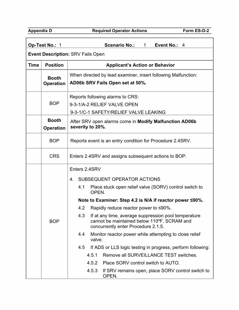
Appendix D Required Operator Actions Form ES-D-2
Op-Test No.: 1 Scenario No.: 1 Event No.: 4
Event Description: SRV Fails Open
Time Position Applicant’s Action or Behavior
Booth Operation
When directed by lead examiner, insert following Malfunction: AD06b SRV Fails Open set at 50%.
BOP Reports following alarms to CRS: 9-3-1/A-2 RELIEF VALVE OPEN 9-3-1/C-1 SAFETY/RELIEF VALVE LEAKING
Booth
Operation After SRV open alarms come in Modify Malfunction AD06b severity to 20%.
BOP Reports event is an entry condition for Procedure 2.4SRV.
CRS Enters 2.4SRV and assigns subsequent actions to BOP.
BOP
Enters 2.4SRV
4. SUBSEQUENT OPERATOR ACTIONS 4.1 Place stuck open relief valve (SORV) control switch to
OPEN. Note to Examiner: Step 4.2 is N/A if reactor power ≤90%. 4.2 Rapidly reduce reactor power to ≤90%. 4.3 If at any time, average suppression pool temperature
cannot be maintained below 110ºF, SCRAM and concurrently enter Procedure 2.1.5.
4.4 Monitor reactor power while attempting to close relief valve.
4.5 If ADS or LLS logic testing in progress, perform following: 4.5.1 Remove all SURVEILLANCE TEST switches. 4.5.2 Place SORV control switch to AUTO. 4.5.3 If SRV remains open, place SORV control switch to
OPEN.
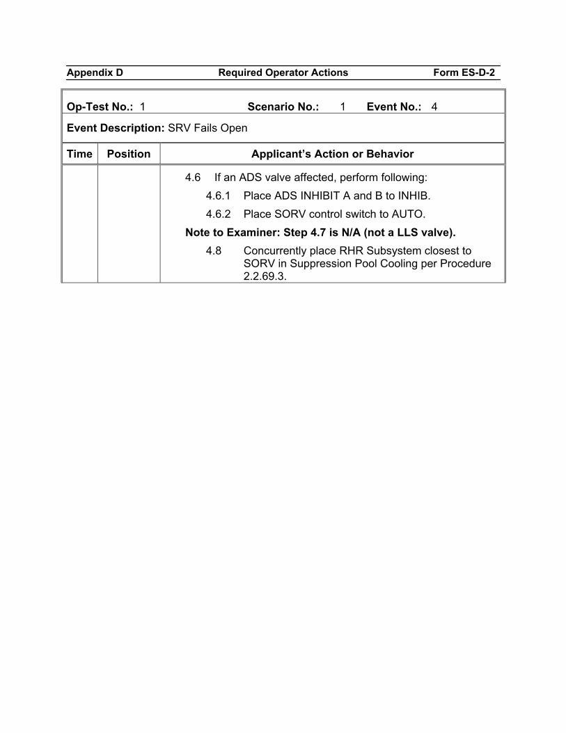
Appendix D Required Operator Actions Form ES-D-2
Op-Test No.: 1 Scenario No.: 1 Event No.: 4
Event Description: SRV Fails Open
Time Position Applicant’s Action or Behavior
4.6 If an ADS valve affected, perform following: 4.6.1 Place ADS INHIBIT A and B to INHIB. 4.6.2 Place SORV control switch to AUTO.
Note to Examiner: Step 4.7 is N/A (not a LLS valve). 4.8 Concurrently place RHR Subsystem closest to
SORV in Suppression Pool Cooling per Procedure 2.2.69.3.
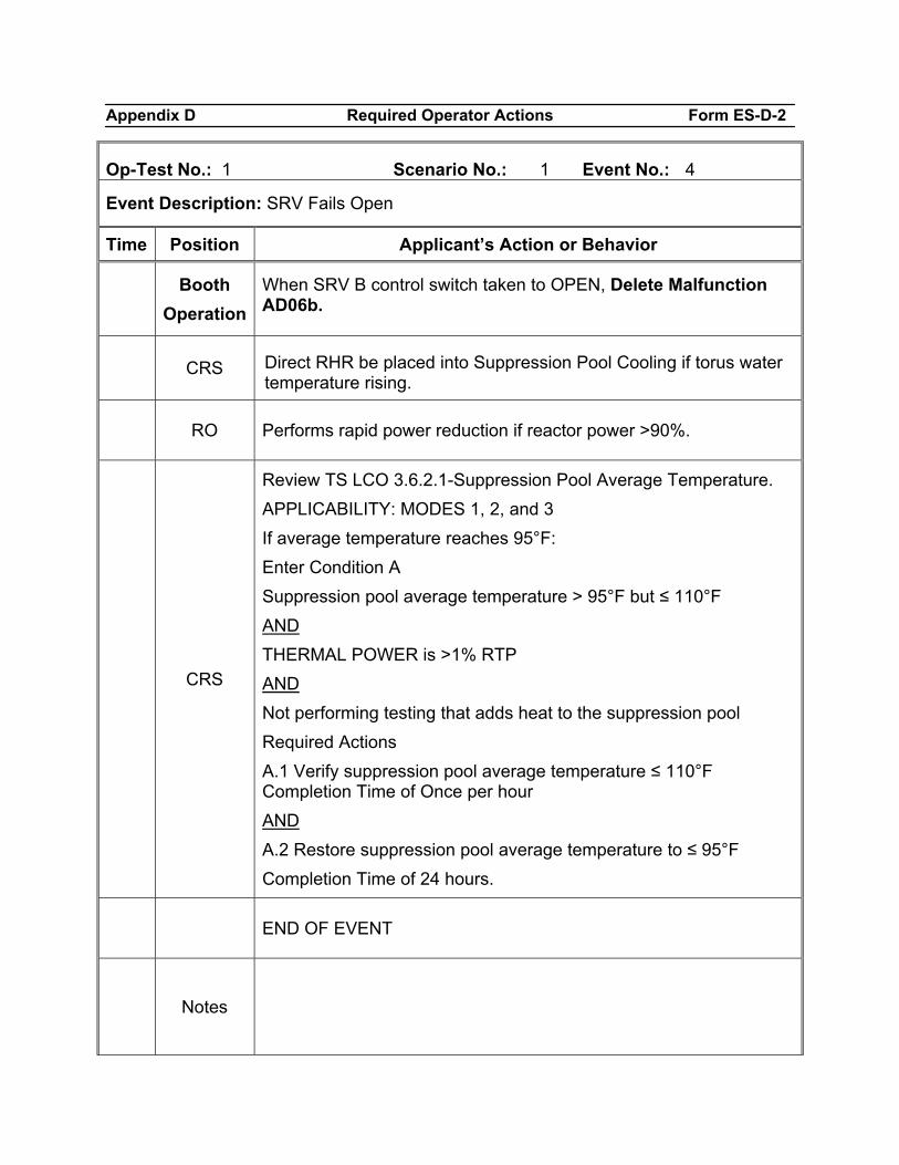
Appendix D Required Operator Actions Form ES-D-2
Op-Test No.: 1 Scenario No.: 1 Event No.: 4
Event Description: SRV Fails Open
Time Position Applicant’s Action or Behavior
Booth
Operation When SRV B control switch taken to OPEN, Delete Malfunction AD06b.
CRS Direct RHR be placed into Suppression Pool Cooling if torus water temperature rising.
RO Performs rapid power reduction if reactor power >90%.
CRS
Review TS LCO 3.6.2.1-Suppression Pool Average Temperature. APPLICABILITY: MODES 1, 2, and 3 If average temperature reaches 95°F: Enter Condition A Suppression pool average temperature > 95°F but ≤ 110°F AND THERMAL POWER is >1% RTP AND Not performing testing that adds heat to the suppression pool Required Actions A.1 Verify suppression pool average temperature ≤ 110°F Completion Time of Once per hour AND A.2 Restore suppression pool average temperature to ≤ 95°F Completion Time of 24 hours.
END OF EVENT
Notes
Appendix D Required Operator Actions Form ES-D-2
Op-Test No.: 1 Scenario No.: 1 Event No.: 4
Event Description: SRV Fails Open
Time Position Applicant’s Action or Behavior
Proceed to the next event at direction of the lead examiner.
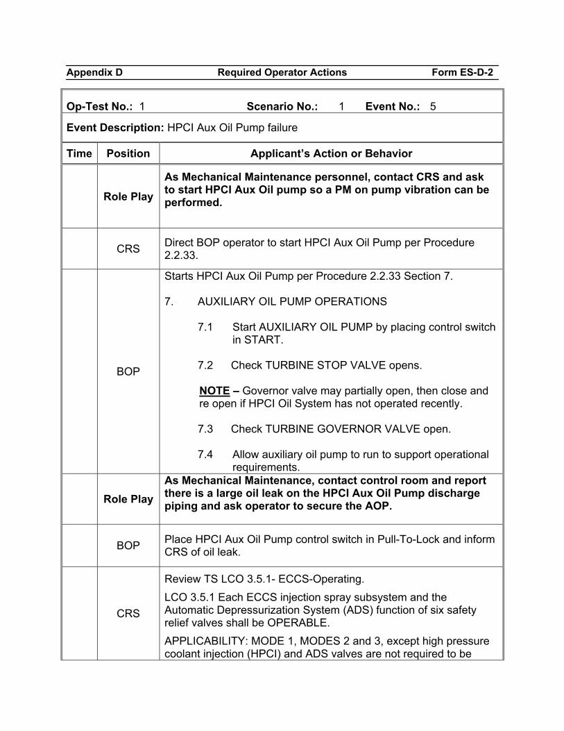
Appendix D Required Operator Actions Form ES-D-2
Op-Test No.: 1 Scenario No.: 1 Event No.: 5
Event Description: HPCI Aux Oil Pump failure
Time Position Applicant’s Action or Behavior
Role Play
As Mechanical Maintenance personnel, contact CRS and ask to start HPCI Aux Oil pump so a PM on pump vibration can be performed.
CRS Direct BOP operator to start HPCI Aux Oil Pump per Procedure 2.2.33.
BOP
Starts HPCI Aux Oil Pump per Procedure 2.2.33 Section 7. 7. AUXILIARY OIL PUMP OPERATIONS
7.1 Start AUXILIARY OIL PUMP by placing control switch in START.
7.2 Check TURBINE STOP VALVE opens.
NOTE – Governor valve may partially open, then close and re open if HPCI Oil System has not operated recently.
7.3 Check TURBINE GOVERNOR VALVE open. 7.4 Allow auxiliary oil pump to run to support operational
requirements.
Role Play As Mechanical Maintenance, contact control room and report there is a large oil leak on the HPCI Aux Oil Pump discharge piping and ask operator to secure the AOP.
BOP Place HPCI Aux Oil Pump control switch in Pull-To-Lock and inform
CRS of oil leak.
CRS
Review TS LCO 3.5.1- ECCS-Operating. LCO 3.5.1 Each ECCS injection spray subsystem and the Automatic Depressurization System (ADS) function of six safety relief valves shall be OPERABLE. APPLICABILITY: MODE 1, MODES 2 and 3, except high pressure coolant injection (HPCI) and ADS valves are not required to be
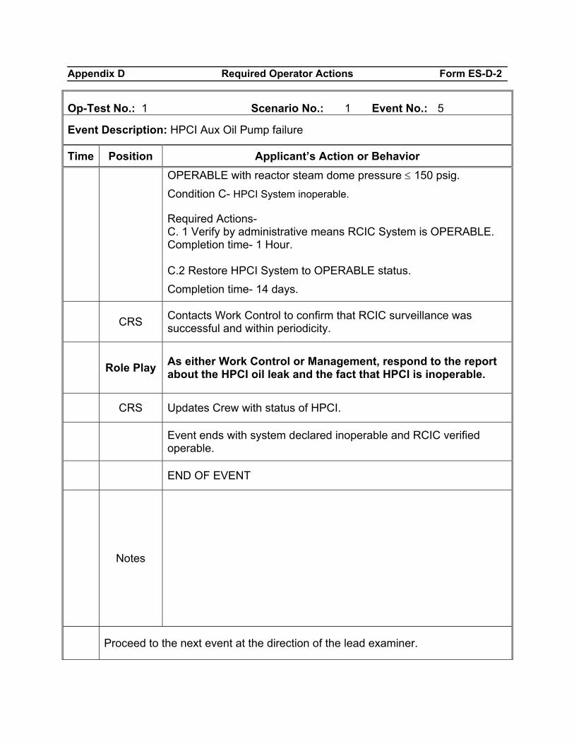
Appendix D Required Operator Actions Form ES-D-2
Op-Test No.: 1 Scenario No.: 1 Event No.: 5
Event Description: HPCI Aux Oil Pump failure
Time Position Applicant’s Action or Behavior OPERABLE with reactor steam dome pressure ≤ 150 psig. Condition C- HPCI System inoperable. Required Actions- C. 1 Verify by administrative means RCIC System is OPERABLE. Completion time- 1 Hour. C.2 Restore HPCI System to OPERABLE status. Completion time- 14 days.
CRS Contacts Work Control to confirm that RCIC surveillance was
successful and within periodicity.
Role Play As either Work Control or Management, respond to the report
about the HPCI oil leak and the fact that HPCI is inoperable.
CRS Updates Crew with status of HPCI.
Event ends with system declared inoperable and RCIC verified operable.
END OF EVENT
Notes
Proceed to the next event at the direction of the lead examiner.
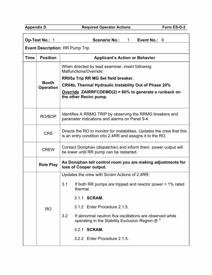
Appendix D Required Operator Actions Form ES-D-2
Op-Test No.: 1 Scenario No.: 1 Event No.: 6
Event Description: RR Pump Trip
Time Position Applicant’s Action or Behavior
Booth Operation
When directed by lead examiner, insert following Malfunctions/Override: RR05a Trip RR MG Set field breaker. CR04b, Thermal Hydraulic Instability Out of Phase 20% Override ZAIRRFCDEMD(2) = 60% to generate a runback on the other Recirc pump.
RO/BOP Identifies A RRMG TRIP by observing the RRMG breakers and parameter indications and alarms on Panel 9-4.
CRS Directs the RO to monitor for instabilities, Updates the crew that this is an entry condition into 2.4RR and assigns it to the RO.
CREW Contact Doniphan (dispatcher) and inform them power output will be lower until RR pump can be restarted.
Role Play As Doniphan tell control room you are making adjustments for loss of Cooper output.
RO
Updates the crew with Scram Actions of 2.4RR: 3.1 If both RR pumps are tripped and reactor power > 1% rated
thermal.
3.1.1 SCRAM.
3.1.2 Enter Procedure 2.1.5.
3.2 If abnormal neutron flux oscillations are observed while operating in the Stability Exclusion Region: 2
3.2.1 SCRAM.
3.2.2 Enter Procedure 2.1.5.
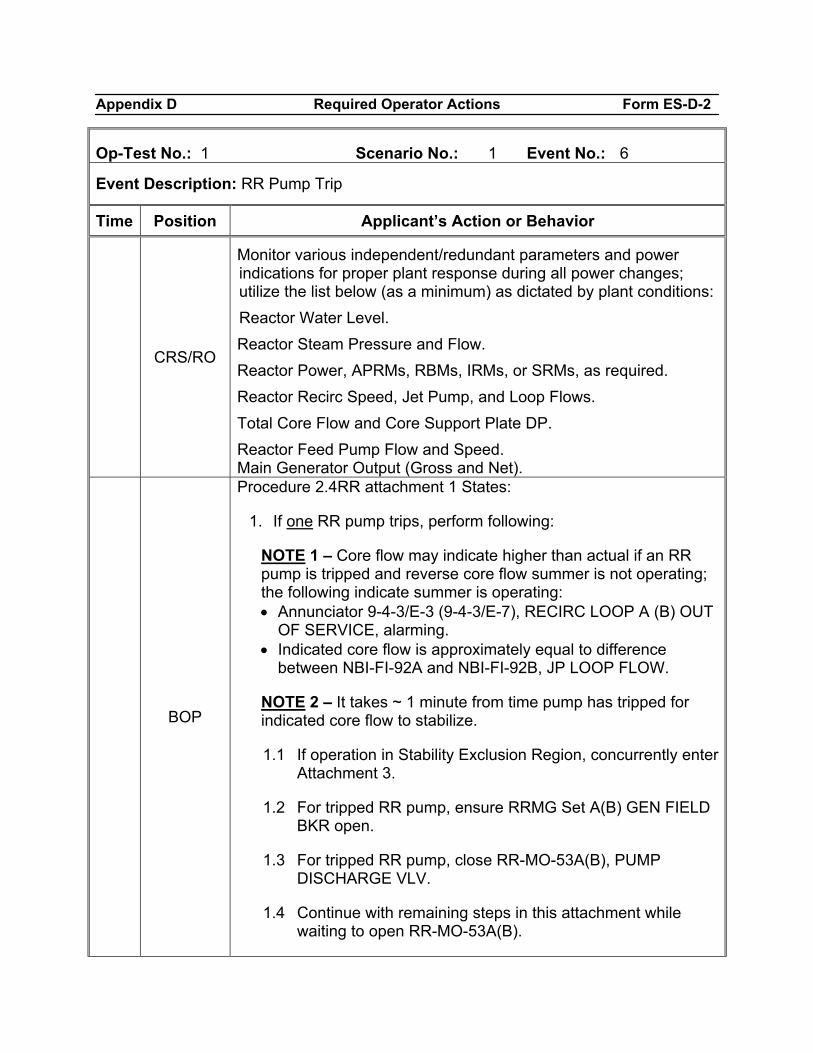
Appendix D Required Operator Actions Form ES-D-2
Op-Test No.: 1 Scenario No.: 1 Event No.: 6
Event Description: RR Pump Trip
Time Position Applicant’s Action or Behavior
CRS/RO
Monitor various independent/redundant parameters and power indications for proper plant response during all power changes; utilize the list below (as a minimum) as dictated by plant conditions: Reactor Water Level. Reactor Steam Pressure and Flow. Reactor Power, APRMs, RBMs, IRMs, or SRMs, as required. Reactor Recirc Speed, Jet Pump, and Loop Flows. Total Core Flow and Core Support Plate DP. Reactor Feed Pump Flow and Speed. Main Generator Output (Gross and Net).
BOP
Procedure 2.4RR attachment 1 States:
1. If one RR pump trips, perform following:
NOTE 1 – Core flow may indicate higher than actual if an RR pump is tripped and reverse core flow summer is not operating; the following indicate summer is operating: • Annunciator 9-4-3/E-3 (9-4-3/E-7), RECIRC LOOP A (B) OUT
OF SERVICE, alarming. • Indicated core flow is approximately equal to difference
between NBI-FI-92A and NBI-FI-92B, JP LOOP FLOW.
NOTE 2 – It takes ~ 1 minute from time pump has tripped for indicated core flow to stabilize.
1.1 If operation in Stability Exclusion Region, concurrently enter Attachment 3.
1.2 For tripped RR pump, ensure RRMG Set A(B) GEN FIELD BKR open.
1.3 For tripped RR pump, close RR-MO-53A(B), PUMP DISCHARGE VLV.
1.4 Continue with remaining steps in this attachment while waiting to open RR-MO-53A(B).
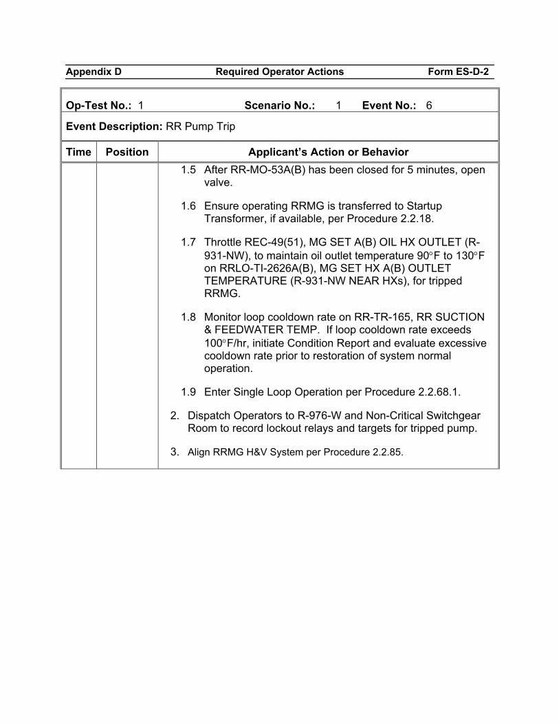
Appendix D Required Operator Actions Form ES-D-2
Op-Test No.: 1 Scenario No.: 1 Event No.: 6
Event Description: RR Pump Trip
Time Position Applicant’s Action or Behavior 1.5 After RR-MO-53A(B) has been closed for 5 minutes, open
valve.
1.6 Ensure operating RRMG is transferred to Startup Transformer, if available, per Procedure 2.2.18.
1.7 Throttle REC-49(51), MG SET A(B) OIL HX OUTLET (R-931-NW), to maintain oil outlet temperature 90°F to 130°F on RRLO-TI-2626A(B), MG SET HX A(B) OUTLET TEMPERATURE (R-931-NW NEAR HXs), for tripped RRMG.
1.8 Monitor loop cooldown rate on RR-TR-165, RR SUCTION & FEEDWATER TEMP. If loop cooldown rate exceeds 100°F/hr, initiate Condition Report and evaluate excessive cooldown rate prior to restoration of system normal operation.
1.9 Enter Single Loop Operation per Procedure 2.2.68.1.
2. Dispatch Operators to R-976-W and Non-Critical Switchgear Room to record lockout relays and targets for tripped pump.
3. Align RRMG H&V System per Procedure 2.2.85.
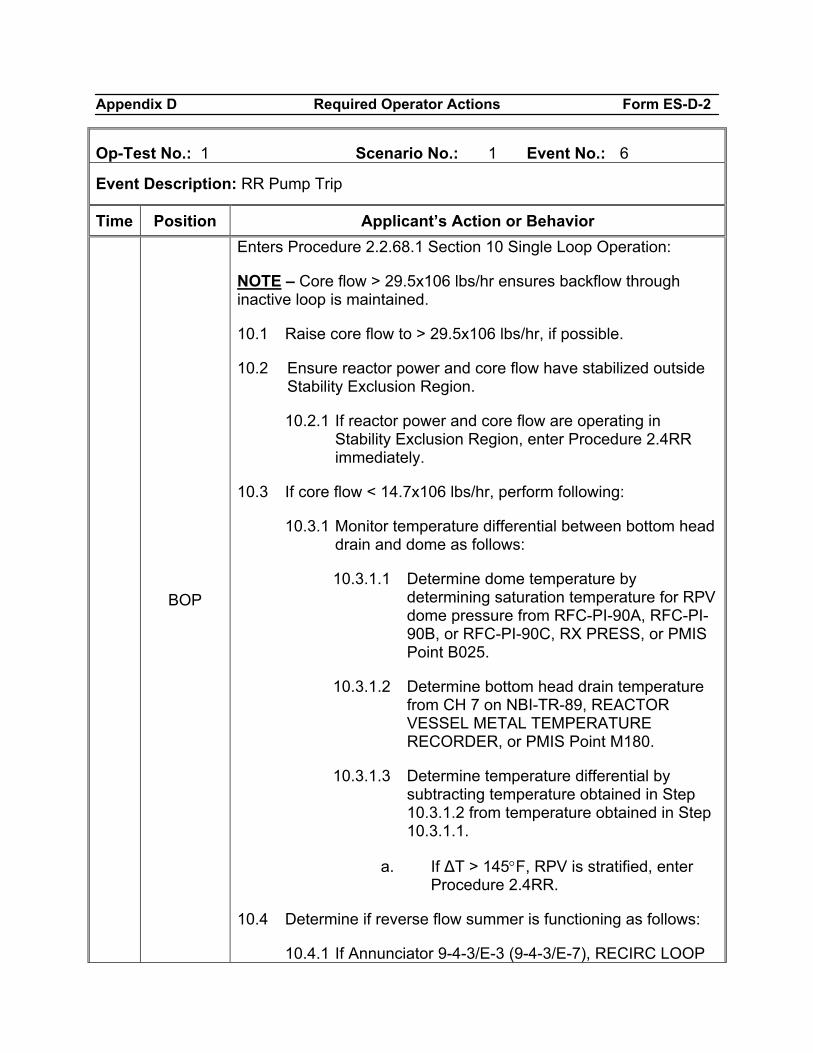
Appendix D Required Operator Actions Form ES-D-2
Op-Test No.: 1 Scenario No.: 1 Event No.: 6
Event Description: RR Pump Trip
Time Position Applicant’s Action or Behavior
BOP
Enters Procedure 2.2.68.1 Section 10 Single Loop Operation:
NOTE – Core flow > 29.5x10⁶ lbs/hr ensures backflow through inactive loop is maintained.
10.1 Raise core flow to > 29.5x10⁶ lbs/hr, if possible.
10.2 Ensure reactor power and core flow have stabilized outside Stability Exclusion Region.
10.2.1 If reactor power and core flow are operating in Stability Exclusion Region, enter Procedure 2.4RR immediately.
10.3 If core flow < 14.7x10⁶ lbs/hr, perform following:
10.3.1 Monitor temperature differential between bottom head drain and dome as follows:
10.3.1.1 Determine dome temperature by determining saturation temperature for RPV dome pressure from RFC-PI-90A, RFC-PI-90B, or RFC-PI-90C, RX PRESS, or PMIS Point B025.
10.3.1.2 Determine bottom head drain temperature from CH 7 on NBI-TR-89, REACTOR VESSEL METAL TEMPERATURE RECORDER, or PMIS Point M180.
10.3.1.3 Determine temperature differential by subtracting temperature obtained in Step 10.3.1.2 from temperature obtained in Step 10.3.1.1.
a. If ∆T > 145°F, RPV is stratified, enter Procedure 2.4RR.
10.4 Determine if reverse flow summer is functioning as follows:
10.4.1 If Annunciator 9-4-3/E-3 (9-4-3/E-7), RECIRC LOOP
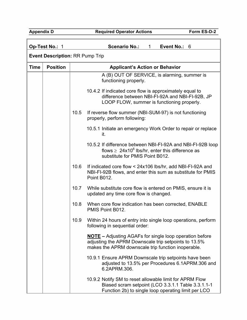
Appendix D Required Operator Actions Form ES-D-2
Op-Test No.: 1 Scenario No.: 1 Event No.: 6
Event Description: RR Pump Trip
Time Position Applicant’s Action or Behavior A (B) OUT OF SERVICE, is alarming, summer is functioning properly.
10.4.2 If indicated core flow is approximately equal to difference between NBI-FI-92A and NBI-FI-92B, JP LOOP FLOW, summer is functioning properly.
10.5 If reverse flow summer (NBI-SUM-97) is not functioning properly, perform following:
10.5.1 Initiate an emergency Work Order to repair or replace it.
10.5.2 If difference between NBI-FI-92A and NBI-FI-92B loop flows ≥ 24x106 lbs/hr, enter this difference as substitute for PMIS Point B012.
10.6 If indicated core flow < 24x106 lbs/hr, add NBI-FI-92A and NBI-FI-92B flows, and enter this sum as substitute for PMIS Point B012.
10.7 While substitute core flow is entered on PMIS, ensure it is updated any time core flow is changed.
10.8 When core flow indication has been corrected, ENABLE PMIS Point B012.
10.9 Within 24 hours of entry into single loop operations, perform following in sequential order:
NOTE – Adjusting AGAFs for single loop operation before adjusting the APRM Downscale trip setpoints to 13.5% makes the APRM downscale trip function inoperable.
10.9.1 Ensure APRM Downscale trip setpoints have been adjusted to 13.5% per Procedures 6.1APRM.306 and 6.2APRM.306.
10.9.2 Notify SM to reset allowable limit for APRM Flow Biased scram setpoint (LCO 3.3.1.1 Table 3.3.1.1-1 Function 2b) to single loop operating limit per LCO
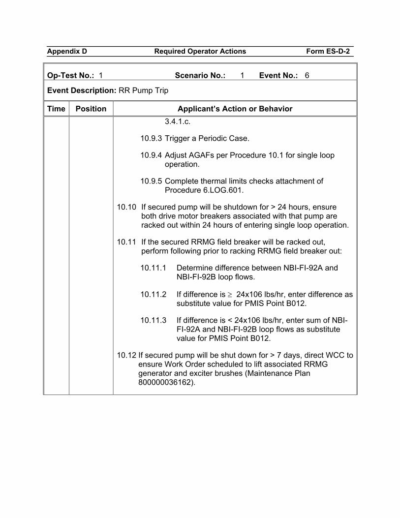
Appendix D Required Operator Actions Form ES-D-2
Op-Test No.: 1 Scenario No.: 1 Event No.: 6
Event Description: RR Pump Trip
Time Position Applicant’s Action or Behavior 3.4.1.c.
10.9.3 Trigger a Periodic Case.
10.9.4 Adjust AGAFs per Procedure 10.1 for single loop operation.
10.9.5 Complete thermal limits checks attachment of Procedure 6.LOG.601.
10.10 If secured pump will be shutdown for > 24 hours, ensure both drive motor breakers associated with that pump are racked out within 24 hours of entering single loop operation.
10.11 If the secured RRMG field breaker will be racked out, perform following prior to racking RRMG field breaker out:
10.11.1 Determine difference between NBI-FI-92A and NBI-FI-92B loop flows.
10.11.2 If difference is ≥ 24x106 lbs/hr, enter difference as substitute value for PMIS Point B012.
10.11.3 If difference is < 24x106 lbs/hr, enter sum of NBI-FI-92A and NBI-FI-92B loop flows as substitute value for PMIS Point B012.
10.12 If secured pump will be shut down for > 7 days, direct WCC to ensure Work Order scheduled to lift associated RRMG generator and exciter brushes (Maintenance Plan 800000036162).
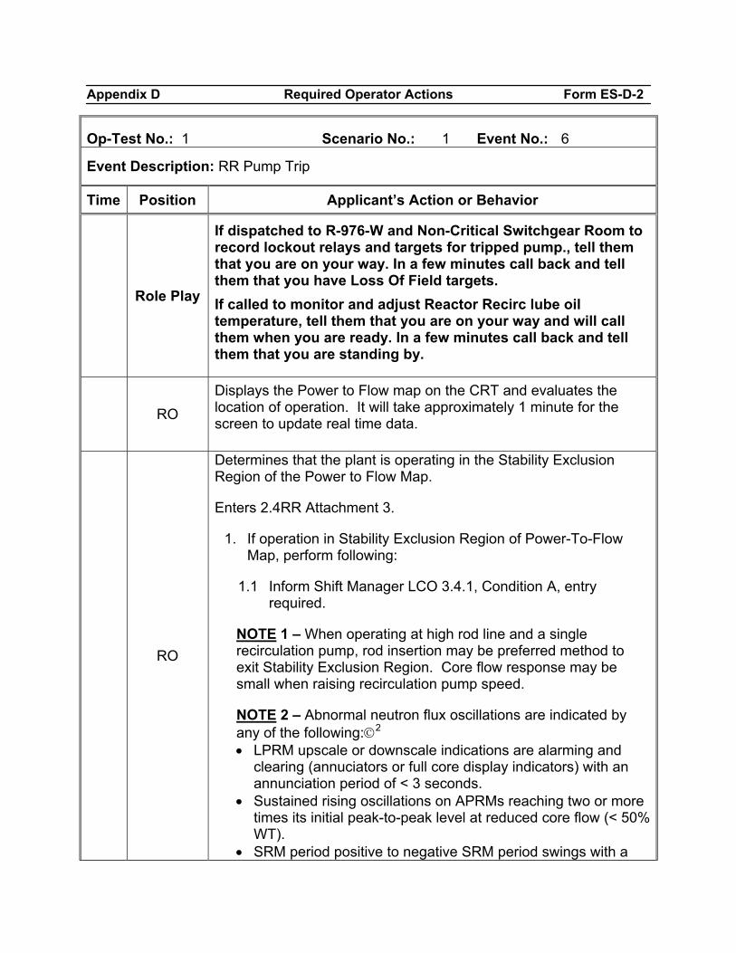
Appendix D Required Operator Actions Form ES-D-2
Op-Test No.: 1 Scenario No.: 1 Event No.: 6
Event Description: RR Pump Trip
Time Position Applicant’s Action or Behavior
Role Play
If dispatched to R-976-W and Non-Critical Switchgear Room to record lockout relays and targets for tripped pump., tell them that you are on your way. In a few minutes call back and tell them that you have Loss Of Field targets. If called to monitor and adjust Reactor Recirc lube oil temperature, tell them that you are on your way and will call them when you are ready. In a few minutes call back and tell them that you are standing by.
RO
Displays the Power to Flow map on the CRT and evaluates the location of operation. It will take approximately 1 minute for the screen to update real time data.
RO
Determines that the plant is operating in the Stability Exclusion Region of the Power to Flow Map.
Enters 2.4RR Attachment 3.
1. If operation in Stability Exclusion Region of Power-To-Flow Map, perform following:
1.1 Inform Shift Manager LCO 3.4.1, Condition A, entry required.
NOTE 1 – When operating at high rod line and a single recirculation pump, rod insertion may be preferred method to exit Stability Exclusion Region. Core flow response may be small when raising recirculation pump speed.
NOTE 2 – Abnormal neutron flux oscillations are indicated by any of the following:©2 • LPRM upscale or downscale indications are alarming and
clearing (annuciators or full core display indicators) with an annunciation period of < 3 seconds.
• Sustained rising oscillations on APRMs reaching two or more times its initial peak-to-peak level at reduced core flow (< 50% WT).
• SRM period positive to negative SRM period swings with a
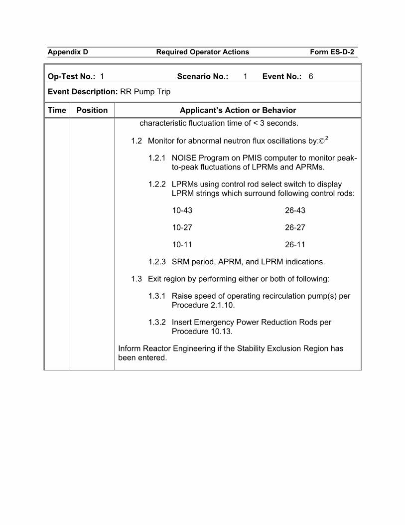
Appendix D Required Operator Actions Form ES-D-2
Op-Test No.: 1 Scenario No.: 1 Event No.: 6
Event Description: RR Pump Trip
Time Position Applicant’s Action or Behavior characteristic fluctuation time of < 3 seconds.
1.2 Monitor for abnormal neutron flux oscillations by:©2
1.2.1 NOISE Program on PMIS computer to monitor peak-to-peak fluctuations of LPRMs and APRMs.
1.2.2 LPRMs using control rod select switch to display LPRM strings which surround following control rods:
10-43 26-43
10-27 26-27
10-11 26-11
1.2.3 SRM period, APRM, and LPRM indications.
1.3 Exit region by performing either or both of following:
1.3.1 Raise speed of operating recirculation pump(s) per Procedure 2.1.10.
1.3.2 Insert Emergency Power Reduction Rods per Procedure 10.13.
Inform Reactor Engineering if the Stability Exclusion Region has been entered.
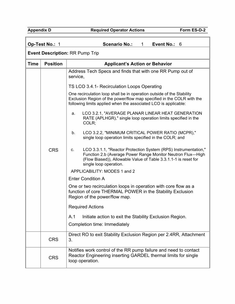
Appendix D Required Operator Actions Form ES-D-2
Op-Test No.: 1 Scenario No.: 1 Event No.: 6
Event Description: RR Pump Trip
Time Position Applicant’s Action or Behavior
CRS
Address Tech Specs and finds that with one RR Pump out of service,
TS LCO 3.4.1- Recirculation Loops Operating One recirculation loop shall be in operation outside of the Stability Exclusion Region of the power/flow map specified in the COLR with the following limits applied when the associated LCO is applicable:
a. LCO 3.2.1, "AVERAGE PLANAR LINEAR HEAT GENERATION RATE (APLHGR)," single loop operation limits specified in the COLR;
b. LCO 3.2.2, "MINIMUM CRITICAL POWER RATIO (MCPR),"
single loop operation limits specified in the COLR; and
c. LCO 3.3.1.1, "Reactor Protection System (RPS) Instrumentation," Function 2.b (Average Power Range Monitor Neutron Flux—High (Flow Biased)), Allowable Value of Table 3.3.1.1-1 is reset for single loop operation.
APPLICABILITY: MODES 1 and 2 Enter Condition A One or two recirculation loops in operation with core flow as a function of core THERMAL POWER in the Stability Exclusion Region of the power/flow map.
Required Actions
A.1 Initiate action to exit the Stability Exclusion Region. Completion time: Immediately
CRS Direct RO to exit Stability Exclusion Region per 2.4RR, Attachment 3.
CRS
Notifies work control of the RR pump failure and need to contact Reactor Engineering inserting GARDEL thermal limits for single loop operation.
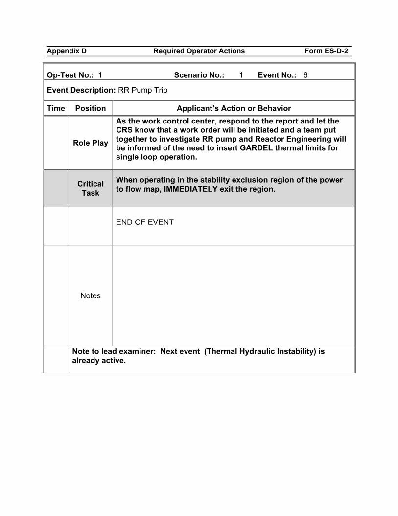
Appendix D Required Operator Actions Form ES-D-2
Op-Test No.: 1 Scenario No.: 1 Event No.: 6
Event Description: RR Pump Trip
Time Position Applicant’s Action or Behavior
Role Play
As the work control center, respond to the report and let the CRS know that a work order will be initiated and a team put together to investigate RR pump and Reactor Engineering will be informed of the need to insert GARDEL thermal limits for single loop operation.
Critical Task
When operating in the stability exclusion region of the power to flow map, IMMEDIATELY exit the region.
END OF EVENT
Notes
Note to lead examiner: Next event (Thermal Hydraulic Instability) is already active.
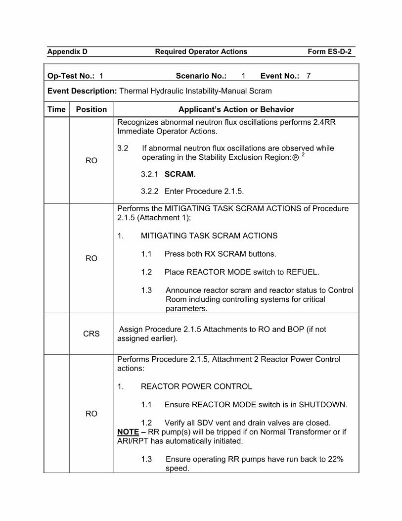
Appendix D Required Operator Actions Form ES-D-2
Op-Test No.: 1 Scenario No.: 1 Event No.: 7
Event Description: Thermal Hydraulic Instability-Manual Scram
Time Position Applicant’s Action or Behavior
RO
Recognizes abnormal neutron flux oscillations performs 2.4RR Immediate Operator Actions.
3.2 If abnormal neutron flux oscillations are observed while operating in the Stability Exclusion Region: 2
3.2.1 SCRAM.
3.2.2 Enter Procedure 2.1.5.
RO
Performs the MITIGATING TASK SCRAM ACTIONS of Procedure 2.1.5 (Attachment 1); 1. MITIGATING TASK SCRAM ACTIONS
1.1 Press both RX SCRAM buttons. 1.2 Place REACTOR MODE switch to REFUEL. 1.3 Announce reactor scram and reactor status to Control
Room including controlling systems for critical parameters.
CRS Assign Procedure 2.1.5 Attachments to RO and BOP (if not assigned earlier).
RO
Performs Procedure 2.1.5, Attachment 2 Reactor Power Control actions: 1. REACTOR POWER CONTROL
1.1 Ensure REACTOR MODE switch is in SHUTDOWN. 1.2 Verify all SDV vent and drain valves are closed.
NOTE – RR pump(s) will be tripped if on Normal Transformer or if ARI/RPT has automatically initiated.
1.3 Ensure operating RR pumps have run back to 22% speed.
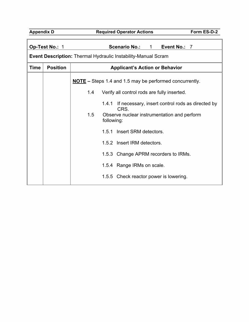
Appendix D Required Operator Actions Form ES-D-2
Op-Test No.: 1 Scenario No.: 1 Event No.: 7
Event Description: Thermal Hydraulic Instability-Manual Scram
Time Position Applicant’s Action or Behavior
NOTE – Steps 1.4 and 1.5 may be performed concurrently.
1.4 Verify all control rods are fully inserted.
1.4.1 If necessary, insert control rods as directed by CRS.
1.5 Observe nuclear instrumentation and perform following:
1.5.1 Insert SRM detectors. 1.5.2 Insert IRM detectors. 1.5.3 Change APRM recorders to IRMs. 1.5.4 Range IRMs on scale. 1.5.5 Check reactor power is lowering.
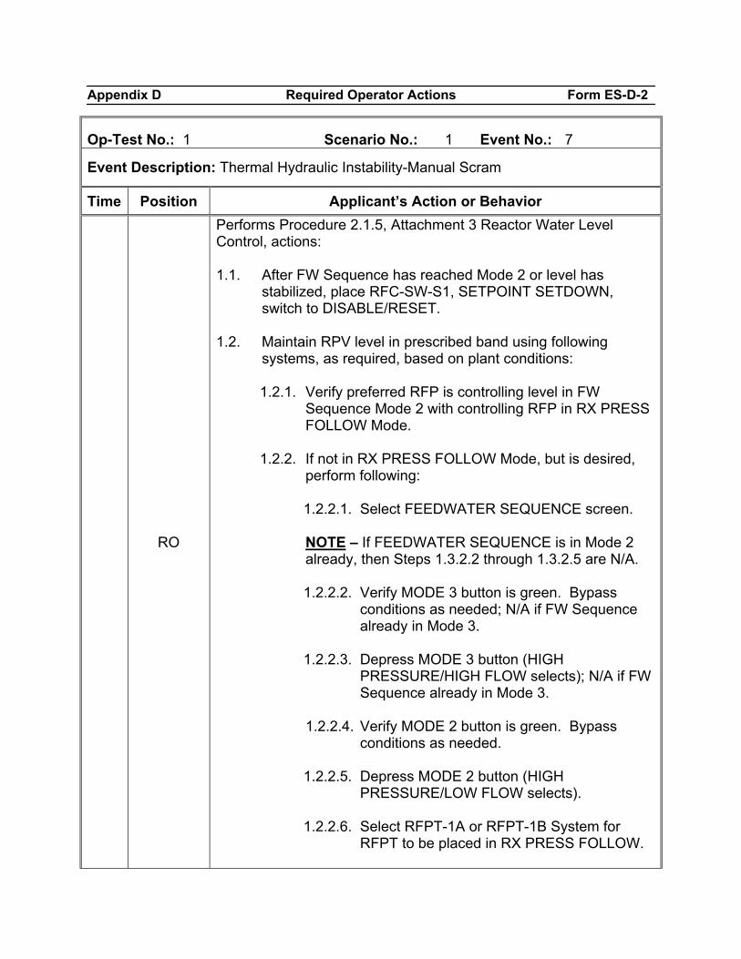
Appendix D Required Operator Actions Form ES-D-2
Op-Test No.: 1 Scenario No.: 1 Event No.: 7
Event Description: Thermal Hydraulic Instability-Manual Scram
Time Position Applicant’s Action or Behavior
RO
Performs Procedure 2.1.5, Attachment 3 Reactor Water Level Control, actions: 1.1. After FW Sequence has reached Mode 2 or level has
stabilized, place RFC-SW-S1, SETPOINT SETDOWN, switch to DISABLE/RESET.
1.2. Maintain RPV level in prescribed band using following
systems, as required, based on plant conditions:
1.2.1. Verify preferred RFP is controlling level in FW Sequence Mode 2 with controlling RFP in RX PRESS FOLLOW Mode.
1.2.2. If not in RX PRESS FOLLOW Mode, but is desired,
perform following:
1.2.2.1. Select FEEDWATER SEQUENCE screen.
NOTE – If FEEDWATER SEQUENCE is in Mode 2 already, then Steps 1.3.2.2 through 1.3.2.5 are N/A.
1.2.2.2. Verify MODE 3 button is green. Bypass
conditions as needed; N/A if FW Sequence already in Mode 3.
1.2.2.3. Depress MODE 3 button (HIGH
PRESSURE/HIGH FLOW selects); N/A if FW Sequence already in Mode 3.
1.2.2.4. Verify MODE 2 button is green. Bypass
conditions as needed. 1.2.2.5. Depress MODE 2 button (HIGH
PRESSURE/LOW FLOW selects).
1.2.2.6. Select RFPT-1A or RFPT-1B System for RFPT to be placed in RX PRESS FOLLOW.
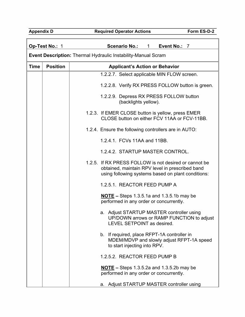
Appendix D Required Operator Actions Form ES-D-2
Op-Test No.: 1 Scenario No.: 1 Event No.: 7
Event Description: Thermal Hydraulic Instability-Manual Scram
Time Position Applicant’s Action or Behavior 1.2.2.7. Select applicable MIN FLOW screen. 1.2.2.8. Verify RX PRESS FOLLOW button is green. 1.2.2.9. Depress RX PRESS FOLLOW button
(backlights yellow).
1.2.3. If EMER CLOSE button is yellow, press EMER CLOSE button on either FCV 11AA or FCV-11BB.
1.2.4. Ensure the following controllers are in AUTO:
1.2.4.1. FCVs 11AA and 11BB.
1.2.4.2. STARTUP MASTER CONTROL.
1.2.5. If RX PRESS FOLLOW is not desired or cannot be
obtained, maintain RPV level in prescribed band using following systems based on plant conditions:
1.2.5.1. REACTOR FEED PUMP A
NOTE – Steps 1.3.5.1a and 1.3.5.1b may be
performed in any order or concurrently.
a. Adjust STARTUP MASTER controller using UP/DOWN arrows or RAMP FUNCTION to adjust LEVEL SETPOINT as desired.
b. If required, place RFPT-1A controller in
MDEM/MDVP and slowly adjust RFPT-1A speed to start injecting into RPV.
1.2.5.2. REACTOR FEED PUMP B
NOTE – Steps 1.3.5.2a and 1.3.5.2b may be
performed in any order or concurrently.
a. Adjust STARTUP MASTER controller using
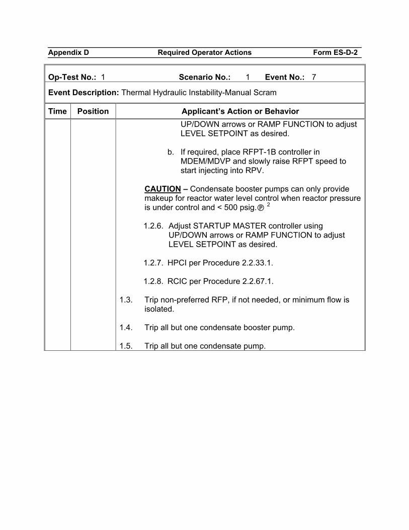
Appendix D Required Operator Actions Form ES-D-2
Op-Test No.: 1 Scenario No.: 1 Event No.: 7
Event Description: Thermal Hydraulic Instability-Manual Scram
Time Position Applicant’s Action or Behavior UP/DOWN arrows or RAMP FUNCTION to adjust LEVEL SETPOINT as desired.
b. If required, place RFPT-1B controller in
MDEM/MDVP and slowly raise RFPT speed to start injecting into RPV.
CAUTION – Condensate booster pumps can only provide
makeup for reactor water level control when reactor pressure is under control and < 500 psig. 2
1.2.6. Adjust STARTUP MASTER controller using
UP/DOWN arrows or RAMP FUNCTION to adjust LEVEL SETPOINT as desired.
1.2.7. HPCI per Procedure 2.2.33.1.
1.2.8. RCIC per Procedure 2.2.67.1.
1.3. Trip non-preferred RFP, if not needed, or minimum flow is
isolated. 1.4. Trip all but one condensate booster pump. 1.5. Trip all but one condensate pump.
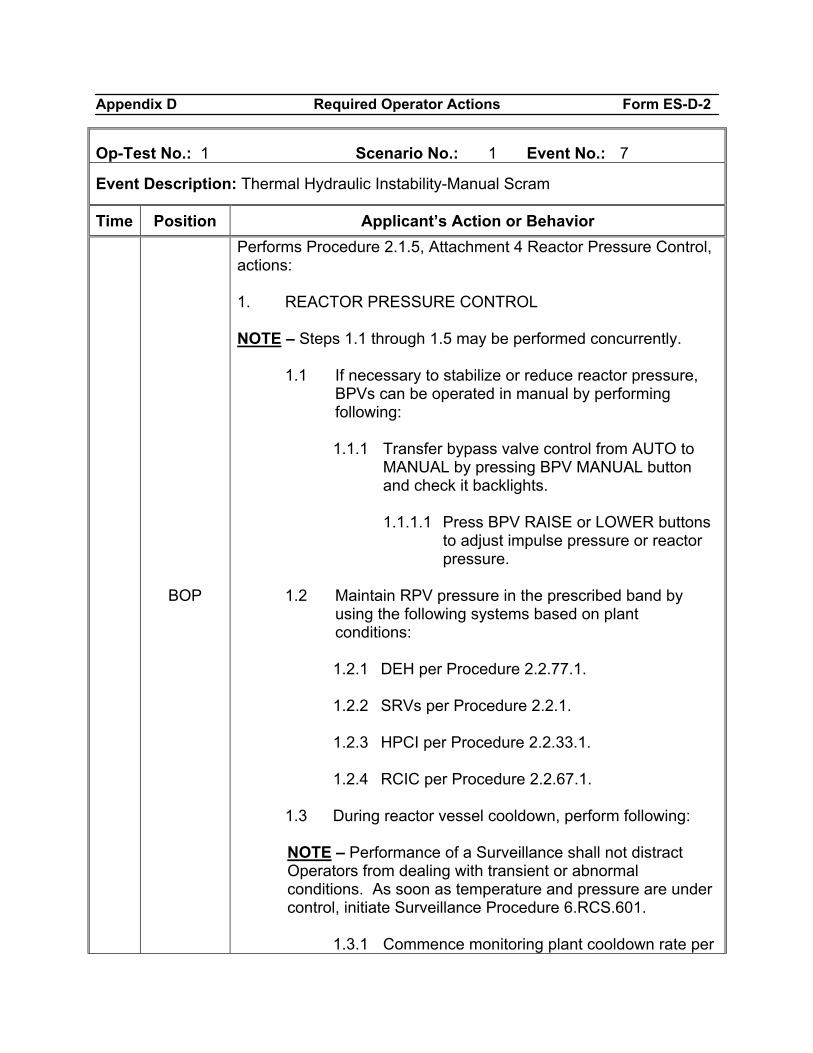
Appendix D Required Operator Actions Form ES-D-2
Op-Test No.: 1 Scenario No.: 1 Event No.: 7
Event Description: Thermal Hydraulic Instability-Manual Scram
Time Position Applicant’s Action or Behavior
BOP
Performs Procedure 2.1.5, Attachment 4 Reactor Pressure Control, actions: 1. REACTOR PRESSURE CONTROL NOTE – Steps 1.1 through 1.5 may be performed concurrently.
1.1 If necessary to stabilize or reduce reactor pressure, BPVs can be operated in manual by performing following:
1.1.1 Transfer bypass valve control from AUTO to
MANUAL by pressing BPV MANUAL button and check it backlights.
1.1.1.1 Press BPV RAISE or LOWER buttons
to adjust impulse pressure or reactor pressure.
1.2 Maintain RPV pressure in the prescribed band by
using the following systems based on plant conditions:
1.2.1 DEH per Procedure 2.2.77.1.
1.2.2 SRVs per Procedure 2.2.1.
1.2.3 HPCI per Procedure 2.2.33.1.
1.2.4 RCIC per Procedure 2.2.67.1.
1.3 During reactor vessel cooldown, perform following:
NOTE – Performance of a Surveillance shall not distract
Operators from dealing with transient or abnormal conditions. As soon as temperature and pressure are under control, initiate Surveillance Procedure 6.RCS.601.
1.3.1 Commence monitoring plant cooldown rate per
Appendix D Required Operator Actions Form ES-D-2
Op-Test No.: 1 Scenario No.: 1 Event No.: 7
Event Description: Thermal Hydraulic Instability-Manual Scram
Time Position Applicant’s Action or Behavior Procedure 6.RCS.601 1
1.3.2 Maintain average cooldown rate ≤90°F/hr.
1.4 If plant conditions require limiting cooldown rate or
main steam flow, perform Steps 1.4.1 through 1.4.5, as necessary.
1.4.1 Start mechanical vacuum pumps per
Procedure 2.2.55.
1.4.2 Secure SJAEs per Procedure 2.2.55.
1.4.3 Start HPCI or RCIC, as necessary, to control RPV level.
1.4.4 To minimize steam flow, perform following:
1.4.4.1 Close following valves:
a. VLV AO-80A, INBOARD STEAM
ISOLATION.
b. VLV AO-80B, INBOARD STEAM ISOLATION.
c. VLV AO-80C, INBOARD STEAM
ISOLATION.
d. VLV AO-80D, INBOARD STEAM ISOLATION.
1.4.4.2 Ensure MS-MO-79, RO BYPASS VLV,
is closed.
1.4.4.3 Ensure MS-MO-77, OUTBD ISOL VLV, is open.
1.4.4.4 Throttle MS-MO-79, RO BYPASS
Appendix D Required Operator Actions Form ES-D-2
Op-Test No.: 1 Scenario No.: 1 Event No.: 7
Event Description: Thermal Hydraulic Instability-Manual Scram
Time Position Applicant’s Action or Behavior VLV, or MS-MO-78, OUTBD THROTTLE VLV, as necessary, to control steam flow/cooldown rate.
1.4.5 To stop all steam flow, close following valves:
1.4.5.1 MS-AO-AO86A, OUTBOARD STEAM
ISOLATION.
1.4.5.2 MS-AO-AO86B, OUTBOARD STEAM ISOLATION.
1.4.5.3 MS-AO-AO86C, OUTBOARD STEAM
ISOLATION.
1.4.5.4 MS-AO-AO86D, OUTBOARD STEAM ISOLATION.
1.4.5.5 MS-AO-AO80A, INBOARD STEAM
ISOLATION.
1.4.5.6 MS-AO-AO80B, INBOARD STEAM ISOLATION.
1.4.5.7 MS-AO-AO80C, INBOARD STEAM
ISOLATION. 1.4.5.8 MS-AO-AO80D, INBOARD STEAM
ISOLATION. 1.4.5.9 MS-MO-74, INBD ISOL VLV. 1.4.5.10 MS-MO-77, OUTBD ISOL VLV. 1.4.5.11 MS-MO-78, OUTBD THROTTLE VLV. 1.4.5.12 MS-MO-79, RO BYPASS VLV, is
closed.
Appendix D Required Operator Actions Form ES-D-2
Op-Test No.: 1 Scenario No.: 1 Event No.: 7
Event Description: Thermal Hydraulic Instability-Manual Scram
Time Position Applicant’s Action or Behavior 1.4.6 If inboard/outboard MSIVs were closed,
remove feedwater pump from service per Procedure 2.2.28.1.
1.5 Ensure main steam line drains are unisolated as
follows, unless Step 1.4 directed them to be closed:
1.5.1 At Panel 9-4, perform following:
1.5.1.1 Ensure MS-MO-79, RO BYPASS VLV, is closed.
1.5.1.2 Throttle open MS-MO-78, OUTBD
THROTTLE VLV. 1.5.1.3 Open MS-MO-77, OUTBD ISOL VLV.
Appendix D Required Operator Actions Form ES-D-2
Op-Test No.: 1 Scenario No.: 1 Event No.: 7
Event Description: Thermal Hydraulic Instability-Manual Scram
Time Position Applicant’s Action or Behavior
BOP
Performs Procedure 2.1.5, Attachment 5 Balance of Plant, actions: 1. BALANCE OF PLANT ACTIONS
1.1 Verify main turbine automatically tripped or perform following when main generator output 80 MWe: 5
1.1.1 At Panel B, press TURB TRIP 1 and TURB
TRIP 2 buttons for ~ 10 seconds.
1.2 If main turbine does not trip, perform following (N/A if not performed):
1.2.1 Send Operator to locally trip main turbine using
one of following methods:
1.2.1.1 Locally at Trip Tricon Panel (T-932-TG area) [Non-RCA]:
a. Trip main turbine by pressing and
holding TURB TRIP 1 and TURB TRIP 2 buttons for ~ 10 seconds (T-932-N inside Trip TriCon Panel).
1.2.1.2 Locally inside RCA (T-932-TG area
near front standard door):
a. Obtain Hi Rad Key for Turbine Deck from RCA Access, Hi Rad Area Key Locker.
b. OPEN TGF-111, EMERG TRIP
HEADER DRAIN VALVE 1. c. OPEN TGF-112, EMERG TRIP
HEADER DRAIN VALVE 2.
1.2.2 If main turbine does not trip after local actions, stop running DEH pumps (Panel B).
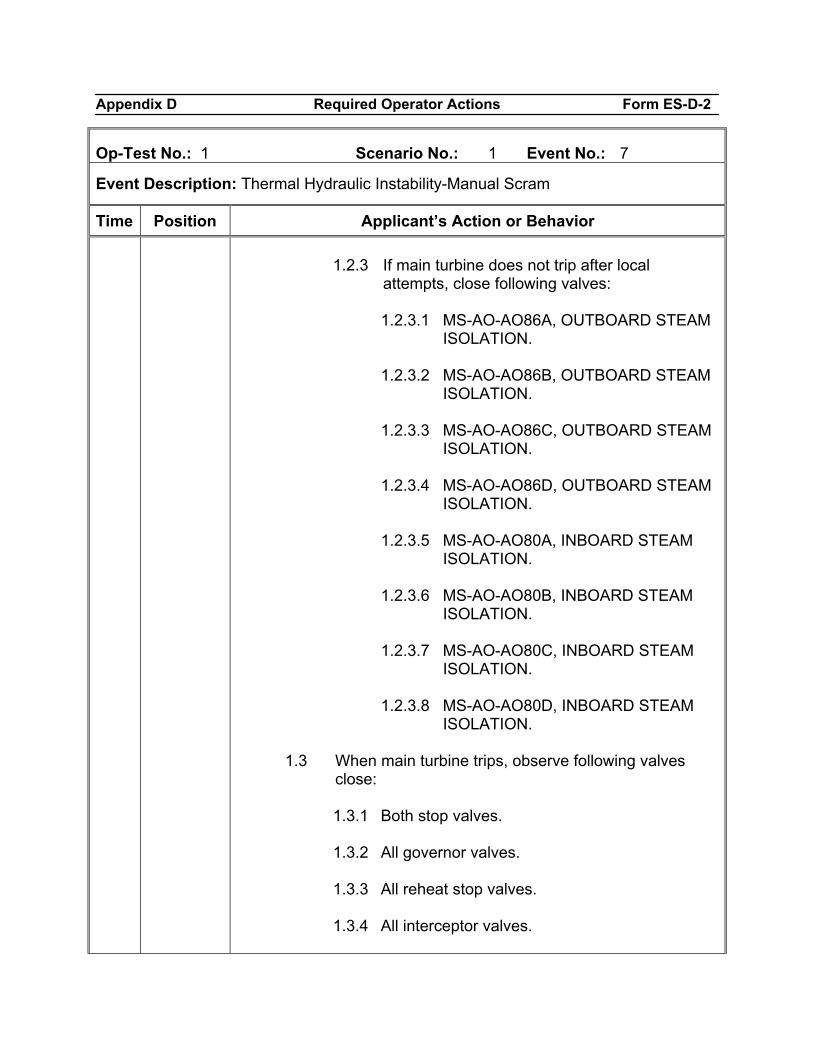
Appendix D Required Operator Actions Form ES-D-2
Op-Test No.: 1 Scenario No.: 1 Event No.: 7
Event Description: Thermal Hydraulic Instability-Manual Scram
Time Position Applicant’s Action or Behavior 1.2.3 If main turbine does not trip after local
attempts, close following valves:
1.2.3.1 MS-AO-AO86A, OUTBOARD STEAM ISOLATION.
1.2.3.2 MS-AO-AO86B, OUTBOARD STEAM
ISOLATION. 1.2.3.3 MS-AO-AO86C, OUTBOARD STEAM
ISOLATION. 1.2.3.4 MS-AO-AO86D, OUTBOARD STEAM
ISOLATION. 1.2.3.5 MS-AO-AO80A, INBOARD STEAM
ISOLATION. 1.2.3.6 MS-AO-AO80B, INBOARD STEAM
ISOLATION. 1.2.3.7 MS-AO-AO80C, INBOARD STEAM
ISOLATION. 1.2.3.8 MS-AO-AO80D, INBOARD STEAM
ISOLATION.
1.3 When main turbine trips, observe following valves close:
1.3.1 Both stop valves. 1.3.2 All governor valves. 1.3.3 All reheat stop valves. 1.3.4 All interceptor valves.
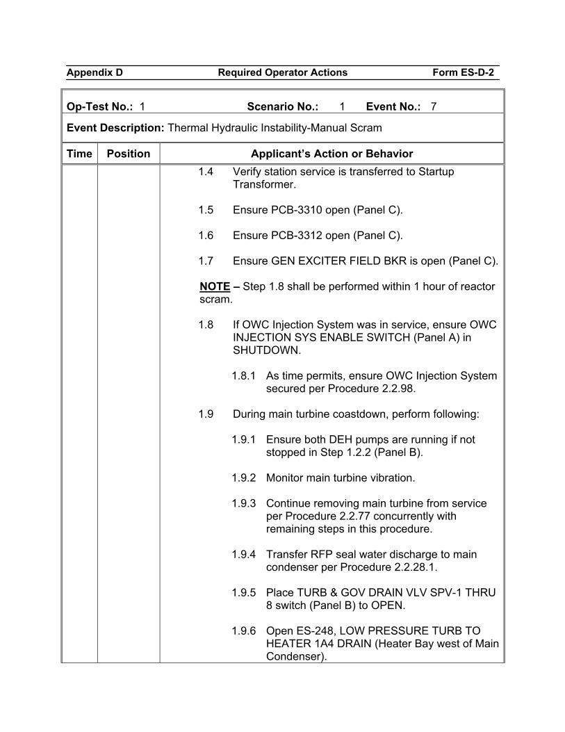
Appendix D Required Operator Actions Form ES-D-2
Op-Test No.: 1 Scenario No.: 1 Event No.: 7
Event Description: Thermal Hydraulic Instability-Manual Scram
Time Position Applicant’s Action or Behavior 1.4 Verify station service is transferred to Startup
Transformer. 1.5 Ensure PCB-3310 open (Panel C). 1.6 Ensure PCB-3312 open (Panel C). 1.7 Ensure GEN EXCITER FIELD BKR is open (Panel C).
NOTE – Step 1.8 shall be performed within 1 hour of reactor
scram.
1.8 If OWC Injection System was in service, ensure OWC INJECTION SYS ENABLE SWITCH (Panel A) in SHUTDOWN.
1.8.1 As time permits, ensure OWC Injection System
secured per Procedure 2.2.98. 1.9 During main turbine coastdown, perform following:
1.9.1 Ensure both DEH pumps are running if not stopped in Step 1.2.2 (Panel B).
1.9.2 Monitor main turbine vibration. 1.9.3 Continue removing main turbine from service
per Procedure 2.2.77 concurrently with remaining steps in this procedure.
1.9.4 Transfer RFP seal water discharge to main
condenser per Procedure 2.2.28.1. 1.9.5 Place TURB & GOV DRAIN VLV SPV-1 THRU
8 switch (Panel B) to OPEN. 1.9.6 Open ES-248, LOW PRESSURE TURB TO
HEATER 1A4 DRAIN (Heater Bay west of Main Condenser).
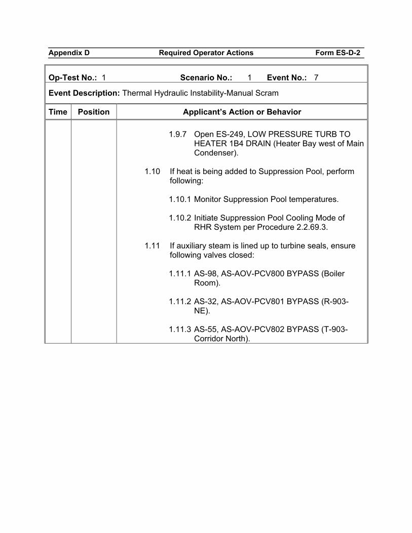
Appendix D Required Operator Actions Form ES-D-2
Op-Test No.: 1 Scenario No.: 1 Event No.: 7
Event Description: Thermal Hydraulic Instability-Manual Scram
Time Position Applicant’s Action or Behavior 1.9.7 Open ES-249, LOW PRESSURE TURB TO
HEATER 1B4 DRAIN (Heater Bay west of Main Condenser).
1.10 If heat is being added to Suppression Pool, perform
following:
1.10.1 Monitor Suppression Pool temperatures. 1.10.2 Initiate Suppression Pool Cooling Mode of
RHR System per Procedure 2.2.69.3. 1.11 If auxiliary steam is lined up to turbine seals, ensure
following valves closed:
1.11.1 AS-98, AS-AOV-PCV800 BYPASS (Boiler Room).
1.11.2 AS-32, AS-AOV-PCV801 BYPASS (R-903-
NE). 1.11.3 AS-55, AS-AOV-PCV802 BYPASS (T-903-
Corridor North).
Appendix D Required Operator Actions Form ES-D-2
Op-Test No.: 1 Scenario No.: 1 Event No.: 7
Event Description: Thermal Hydraulic Instability-Manual Scram
Time Position Applicant’s Action or Behavior
END OF EVENT
Notes
Proceed to the next event at the direction of the lead examiner.
Appendix D Required Operator Actions Form ES-D-2
Op-Test No.: 1 Scenario No.: 1 Event No.: 8
Event Description: Earthquake, Suppression Pool Leak, ED on low SP/L
Time Position Applicant’s Action or Behavior
Booth Operation
When directed by lead examiner, insert Malfunctions: IMF HV02b Major Earthquake set to 25%. IMF PC08 Suppression Pool Water Leak 25% level lowers at -0.2”/min.
BOP/RO
Respond to alarms: B-3/A-1, EMERGENCY SEISMIC HIGH LEVEL B-3/B-1, SEISMIC EVENT
CRS Enters Procedure 5.1QUAKE and assigns Subsequent Operator Actions to BOP.
BOP
Performs 5.1QUAKE Subsequent Operator Actions: 1.1 Validate seismic alarm(s) by any or all of following:
1.1.1 Physical sensation of earth movement. 1.1.2 Seismic instrumentation jarring/vibration by
personnel or equipment (metal enclosure north of Intake).
1.1.3 Contact Ft. Calhoun Station Control Room - (402)
533-6623. 1.1.4 Contact National Earthquake Information Center
at (303) 273-8500. 1.2 If seismic event false and seismic monitor actuated, go
to Step 4.18. 1.3 If only B-3/B-1, SEISMIC EVENT, is valid or cannot be
shown false, continue normal operation. 1.4 If both following alarms are valid or cannot be shown
false, enter Procedure 2.1.4.
Appendix D Required Operator Actions Form ES-D-2
Op-Test No.: 1 Scenario No.: 1 Event No.: 8
Event Description: Earthquake, Suppression Pool Leak, ED on low SP/L
Time Position Applicant’s Action or Behavior 1.4.1 B-3/B-1, SEISMIC EVENT. 1.4.2 B-3/A-1, EMERGENCY SEISMIC HIGH LEVEL.
1.5 If earthquake impacted plant site, perform following:
1.5.1 Visually inspect Independent Spent Fuel Storage Installation (ISFSI) for signs of Horizontal Storage Module (HSM) damage.
1.5.2 If any HSMs are damaged, direct Radiation
Protection to perform a dose survey of ISFSI. 1.5.3 Concurrently enter Procedure 5.1HSM.
1.6 Contact RP Department to conduct radiological surveys
and assist with field walkdowns as necessary. 1.7 If entry into Procedure 2.1.4 is required, prior to starting
shutdown, conduct pre shutdown inspections of following systems using Step 4.9 as a guide: 1.7.1 Reactivity control systems. 1.7.2 RPV pressure control systems. 1.7.3 RPV level control systems. 1.7.4 Decay heat removal systems. 1.7.5 Diesel generators. 1.7.6 Off-site power sources.
1.8 Walk down main Control Room panels to check for
abnormal conditions/indications.
1.8.1 Specific items to check include following:
Appendix D Required Operator Actions Form ES-D-2
Op-Test No.: 1 Scenario No.: 1 Event No.: 8
Event Description: Earthquake, Suppression Pool Leak, ED on low SP/L
Time Position Applicant’s Action or Behavior
1.8.1.1 Reactor power. 1.8.1.2 RPV pressure. 1.8.1.3 RPV level, including cavity level if
flooded up. 1.8.1.4 Core flow. 1.8.1.5 Primary and secondary containment
isolation status. 1.8.1.6 Primary and secondary containment
radiation levels. 1.8.1.7 Primary and secondary containment
temperatures. 1.8.1.8 Vibration monitoring equipment. 1.8.1.9 Tank levels (ECST A, ECST B, CST A,
CST B, etc.). 1.8.1.10 Balance of plant and support systems
for actuations. 1.9 Make detailed inspection of vital and major equipment:
1.9.1 Emphasis should be placed on CSCS and engineered safeguard systems.
1.9.2 Inspection should include areas with industrial
safety significance (e.g., Hydrogen House). 1.9.3 Use following as an inspection guide:
1.9.3.1 Check for leaks in piping systems,
especially at flanged or threaded
Appendix D Required Operator Actions Form ES-D-2
Op-Test No.: 1 Scenario No.: 1 Event No.: 8
Event Description: Earthquake, Suppression Pool Leak, ED on low SP/L
Time Position Applicant’s Action or Behavior connections and branch lines.
1.9.3.2 Check for damage to low pressure
tanks, particularly ground or floor mounted vertical storage tanks.
1.9.3.3 Check for damage to Switchyard
equipment. 1.9.3.4 Check fluid levels in tanks. Level
switches may have been actuated due to sloshing of contained fluid (an actual but momentary change in level).
1.9.3.5 Check for high vibration, high bearing
temperature, and unusual noise in rotating equipment such as pumps and fans.
1.9.3.6 Check for damage to equipment and
structures due to impact with adjacent equipment and falling objects.
1.9.3.7 Check condition of a sampling of
equipment anchorage including deformation or loosening of anchor bolts, pullout or shear of anchor bolts, rocking, sliding, or mis-alignment of equipment.
1.9.3.8 Check for damage to attached piping
including hoses, tubing, and electrical conduit.
1.9.3.9 Check for damage to piping and piping
supports for evidence of excessive displacement.
1.9.3.10 Check for distortion of electrical and
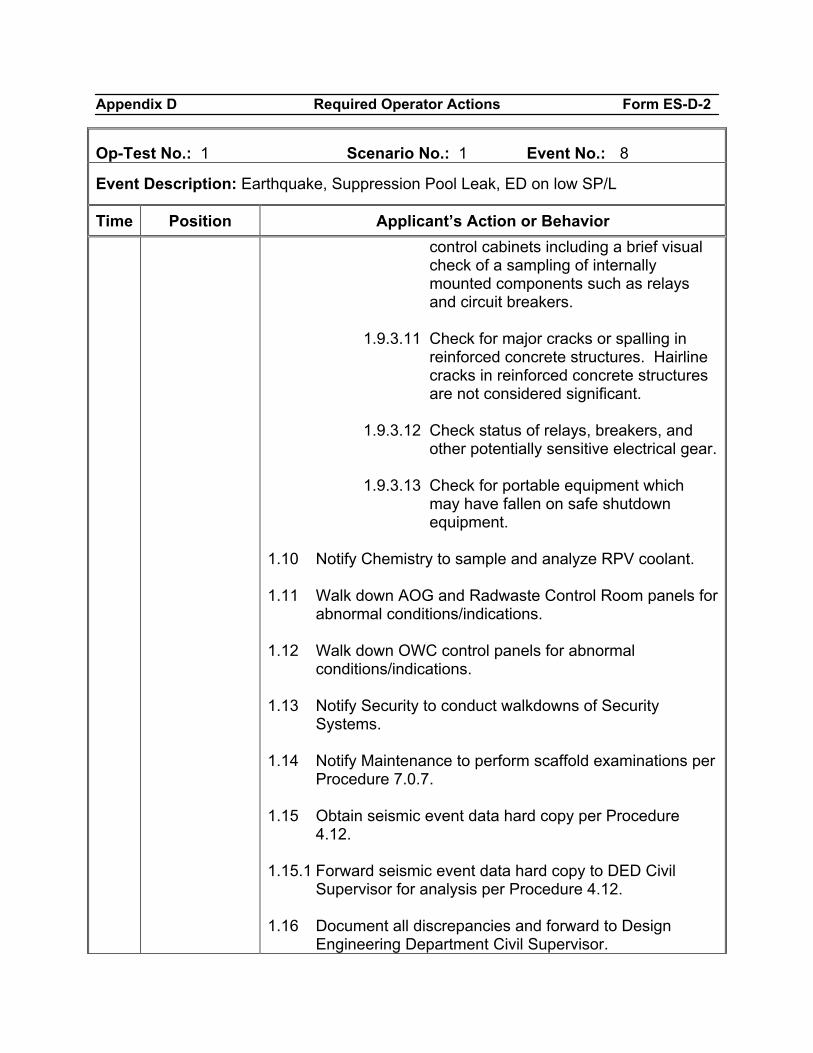
Appendix D Required Operator Actions Form ES-D-2
Op-Test No.: 1 Scenario No.: 1 Event No.: 8
Event Description: Earthquake, Suppression Pool Leak, ED on low SP/L
Time Position Applicant’s Action or Behavior control cabinets including a brief visual check of a sampling of internally mounted components such as relays and circuit breakers.
1.9.3.11 Check for major cracks or spalling in
reinforced concrete structures. Hairline cracks in reinforced concrete structures are not considered significant.
1.9.3.12 Check status of relays, breakers, and
other potentially sensitive electrical gear. 1.9.3.13 Check for portable equipment which
may have fallen on safe shutdown equipment.
1.10 Notify Chemistry to sample and analyze RPV coolant. 1.11 Walk down AOG and Radwaste Control Room panels for
abnormal conditions/indications. 1.12 Walk down OWC control panels for abnormal
conditions/indications. 1.13 Notify Security to conduct walkdowns of Security
Systems. 1.14 Notify Maintenance to perform scaffold examinations per
Procedure 7.0.7. 1.15 Obtain seismic event data hard copy per Procedure
4.12. 1.15.1 Forward seismic event data hard copy to DED Civil
Supervisor for analysis per Procedure 4.12. 1.16 Document all discrepancies and forward to Design
Engineering Department Civil Supervisor.
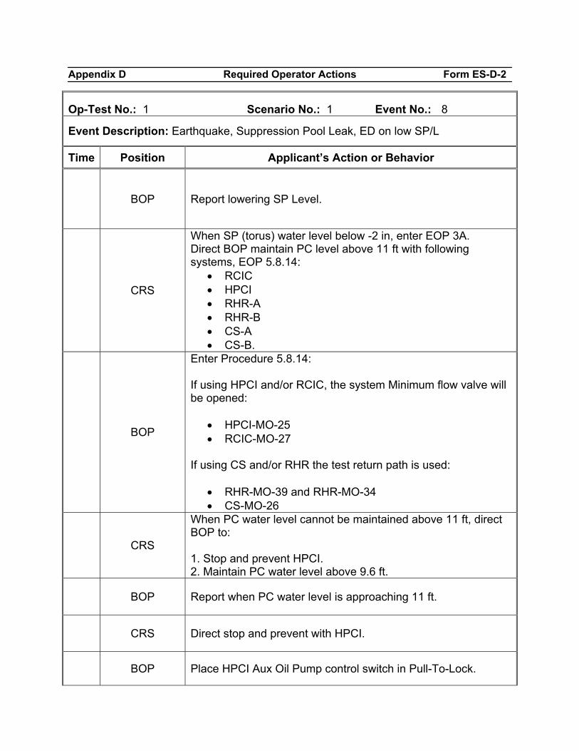
Appendix D Required Operator Actions Form ES-D-2
Op-Test No.: 1 Scenario No.: 1 Event No.: 8
Event Description: Earthquake, Suppression Pool Leak, ED on low SP/L
Time Position Applicant’s Action or Behavior
BOP Report lowering SP Level.
CRS
When SP (torus) water level below -2 in, enter EOP 3A. Direct BOP maintain PC level above 11 ft with following systems, EOP 5.8.14:
• RCIC • HPCI • RHR-A • RHR-B • CS-A • CS-B.
BOP
Enter Procedure 5.8.14: If using HPCI and/or RCIC, the system Minimum flow valve will be opened:
• HPCI-MO-25 • RCIC-MO-27
If using CS and/or RHR the test return path is used:
• RHR-MO-39 and RHR-MO-34 • CS-MO-26
CRS
When PC water level cannot be maintained above 11 ft, direct BOP to: 1. Stop and prevent HPCI. 2. Maintain PC water level above 9.6 ft.
BOP Report when PC water level is approaching 11 ft.
CRS Direct stop and prevent with HPCI.
BOP Place HPCI Aux Oil Pump control switch in Pull-To-Lock.
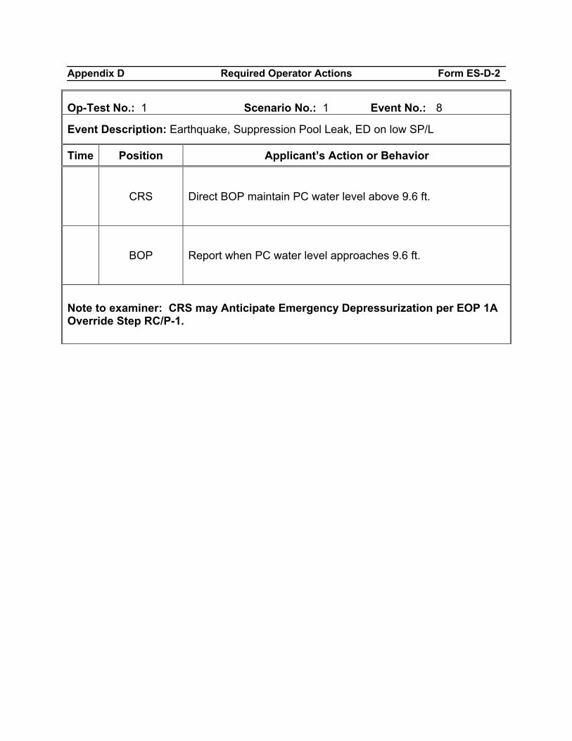
Appendix D Required Operator Actions Form ES-D-2
Op-Test No.: 1 Scenario No.: 1 Event No.: 8
Event Description: Earthquake, Suppression Pool Leak, ED on low SP/L
Time Position Applicant’s Action or Behavior
CRS Direct BOP maintain PC water level above 9.6 ft.
BOP Report when PC water level approaches 9.6 ft.
Note to examiner: CRS may Anticipate Emergency Depressurization per EOP 1A Override Step RC/P-1.
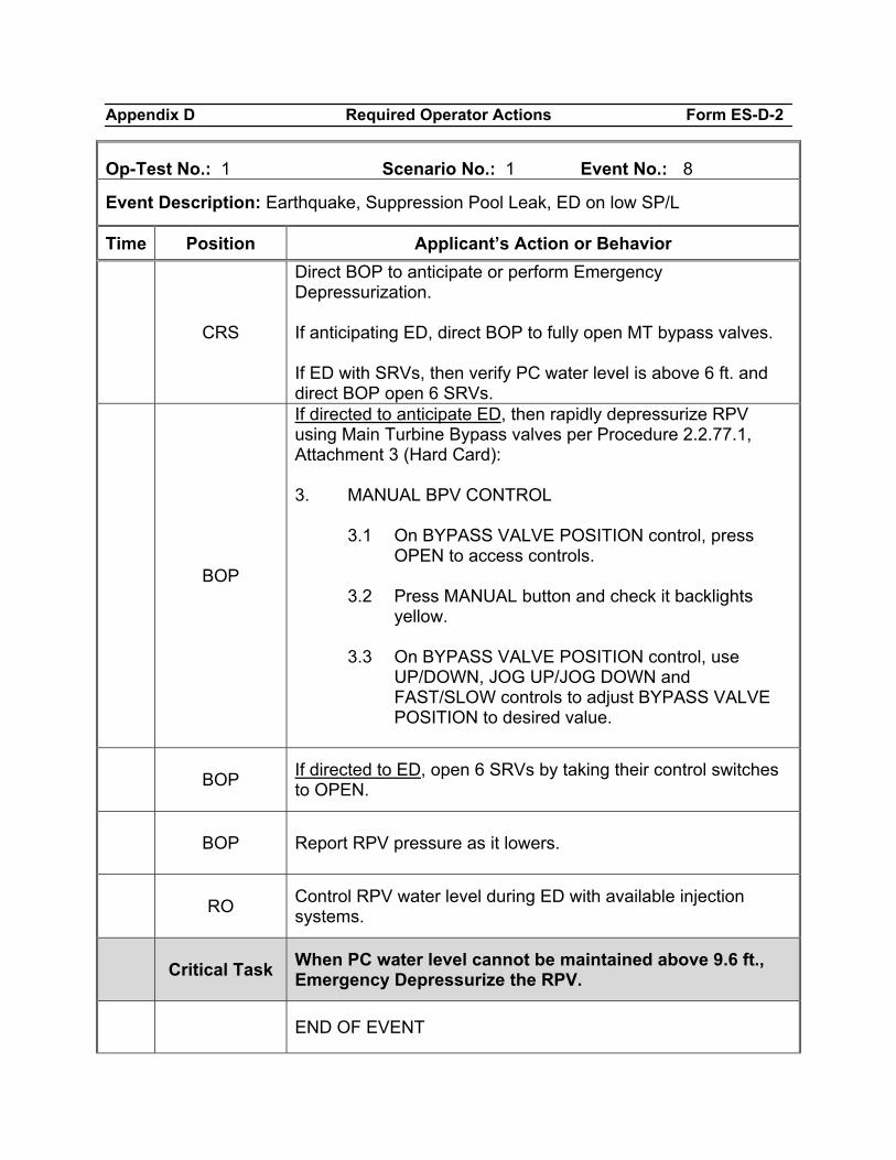
Appendix D Required Operator Actions Form ES-D-2
Op-Test No.: 1 Scenario No.: 1 Event No.: 8
Event Description: Earthquake, Suppression Pool Leak, ED on low SP/L
Time Position Applicant’s Action or Behavior
CRS
Direct BOP to anticipate or perform Emergency Depressurization. If anticipating ED, direct BOP to fully open MT bypass valves. If ED with SRVs, then verify PC water level is above 6 ft. and direct BOP open 6 SRVs.
BOP
If directed to anticipate ED, then rapidly depressurize RPV using Main Turbine Bypass valves per Procedure 2.2.77.1, Attachment 3 (Hard Card): 3. MANUAL BPV CONTROL
3.1 On BYPASS VALVE POSITION control, press OPEN to access controls.
3.2 Press MANUAL button and check it backlights
yellow. 3.3 On BYPASS VALVE POSITION control, use
UP/DOWN, JOG UP/JOG DOWN and FAST/SLOW controls to adjust BYPASS VALVE POSITION to desired value.
BOP If directed to ED, open 6 SRVs by taking their control switches to OPEN.
BOP Report RPV pressure as it lowers.
RO Control RPV water level during ED with available injection systems.
Critical Task When PC water level cannot be maintained above 9.6 ft., Emergency Depressurize the RPV.
END OF EVENT
Appendix D Required Operator Actions Form ES-D-2
Op-Test No.: 1 Scenario No.: 1 Event No.: 8
Event Description: Earthquake, Suppression Pool Leak, ED on low SP/L
Time Position Applicant’s Action or Behavior
Notes
When ED is complete (RPV pressure < 50 psig above Torus pressure), RPV level is controlled in desired band and lead examiner has observed enough of the scenario, then terminate the scenario.
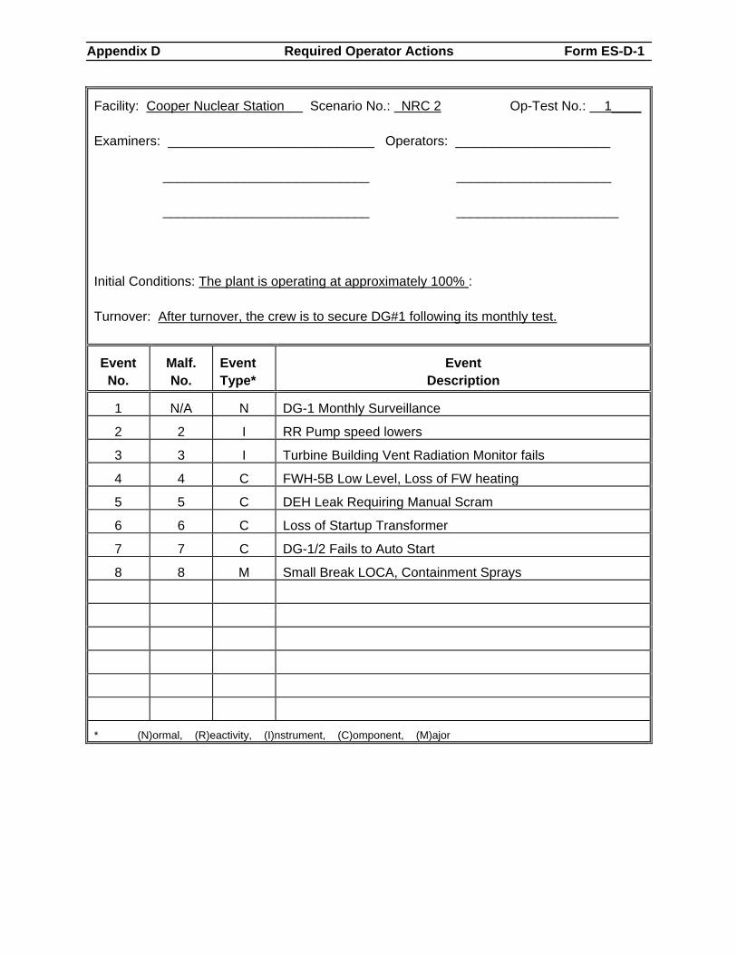
Appendix D Required Operator Actions Form ES-D-1
Facility: Cooper Nuclear Station Scenario No.: NRC 2 Op-Test No.: 1____ Examiners: ____________________________ Operators: _____________________
____________________________ _____________________ ____________________________ ______________________
Initial Conditions: The plant is operating at approximately 100% : Turnover: After turnover, the crew is to secure DG#1 following its monthly test.
Event No.
Malf. No.
Event Type*
Event Description
1 N/A N DG-1 Monthly Surveillance
2 2 I RR Pump speed lowers
3 3 I Turbine Building Vent Radiation Monitor fails
4 4 C FWH-5B Low Level, Loss of FW heating
5 5 C DEH Leak Requiring Manual Scram
6 6 C Loss of Startup Transformer
7 7 C DG-1/2 Fails to Auto Start
8 8 M Small Break LOCA, Containment Sprays
* (N)ormal, (R)eactivity, (I)nstrument, (C)omponent, (M)ajor
Appendix D Required Operator Actions Form ES-D-1
Scenario Objective Evaluate the crew’s ability to perform normal surveillances and to respond to instrument and component failures during non-emergency conditions. Evaluate the crew’s response to a rising reactor power level and a lowering Turbine High Pressure Fluid Reservoir. Evaluate the crew’s response to a small break LOCA which causes Drywell temperatures and pressures to rise and before 280°F in the Drywell the crew initiates Drywell Sprays to maintain temperature below 280°F. Scenario Summary Initial Conditions:
• The plant is operating at approximately 100% power • No equipment out of service. • 6.1DG.101 is in progress. • DG-1 load was lowered to 1000 kW 5 minutes ago.
Events:
• DG-1 Monthly Surveillance • RR Pump speed lowers • Turbine Building Vent Radiation Monitor fails • FWH B-5 Low Level Loss of FW heating • DEH Leak Requiring Manual Scram • Loss of Startup Transformer • DG-1/2 Fails to Auto Start • Small break LOCA • Containment Spray
Scenario Sequence
• Normal activity - DG-1 Monthly Surveillance • Instrument Failure – RR speed lowers • Instrument Failure - Turbine Building Vent Radiation Monitor fails • Component Failure before EOPs – FWH B-5 Low Level Loss of FW heating • Component Failure before EOPs - DEH Leak Requiring Manual Scram • Component Failure after EOPs - Loss of Startup Transformer • Component Failure after EOPs - DG-1/2 Fails to Auto Start • Major Failure – Small break LOCA, with raising DW temperature and pressure • Accident mitigation strategy - Containment Sprays
Appendix D Required Operator Actions Form ES-D-1
Event One: DG-1 Monthly Surveillance Malfunction Required: No malfunction required; this is a normal manipulation for the BOP. Objective: Evaluate the crew during normal surveillance activities. Evaluate the BOP Operator unloading and securing DG1 in accordance with 6.1DG.101, 31 day load test. Success Path: The #1 DG is unloaded from 1000 KW and the engine is secured in accordance with the surveillance procedure. Event Two: RR Pump speed lowers Malfunction Required: RR17b set at 70%. Override ZDIRRMGSWS16B(1) set to ON. Objective: Evaluate the crew’s response to a failed Jordan RR controller. Evaluate the CRS addressing Technical Specifications for RR loop mismatch. Success Path: RR Pump A speed is lowered until both loop flows are balanced within specification. The CRS will review Tech Specs LCO 3.4.1 and consider RR Pump B not in service until pump speeds are matched. Event Three: Turbine Building Vent Radiation Monitor fails Malfunction Required: RM02J Gas Radiation Monitor Turbine Building Normal Range Kaman RMV-RM-20A in at 100% fails the instrument upscale. Objective: Evaluate the crew’s response to the failure of the normal range KAMAN and takes appropriate action in accordance with the Annunciator Procedure. Evaluate the CRS addressing Technical Specifications, TRM and ODAM. Success Path: Alternate sampling of this release path is requested of Radiation Protection to be installed to provide compensatory actions in accordance with TRM T3.3.3; and ODAM DLCO 3.3.2
Appendix D Required Operator Actions Form ES-D-1
Event Four: FWH B-5 High Level Trip Malfunction Required: FW20b 1B-5 FW heater level controller failure high. 20% Objective: Evaluate the crew’s response to Annunciator A-2/C-5 HEATER LOW LEVEL and A-2/C-6 HEATER HIGH LEVEL TRIP. Evaluate the BOP Operator’s entry into Abnormal Procedure 2.4EX-STM. Evaluate the ATC Operator lowering power in response to a lowering feedwater temperature. Success Path: Reactor Power has been lowered to the value less than it was prior to the feedwater heater level problem. Event Five: DEH Leak Requiring Manual Scram Malfunction Required: TC10 Turbine High Press Fluid leak set at 15%. TC09d Governor Valve #4 Failure to 0% over 2.5 minutes. Objective: Evaluate the crew’s response to a lowering Turbine High Pressure Fluid reservoir level and Fluid leak on the #4 Turbine Governor Valve. Evaluate the pre-staging and conservative decision making prior to the need to Scram the Reactor prior to losing Turbine High Pressure Fluid Pumps and control of Turbine GVs, Stop Valves and Bypass Valves. Success Path: Reactor is scrammed and pressure control is transferred to HPCI and SRVs. Event Six: Loss of Startup Transformer Malfunction Required: ED05 Loss of Power (Startup Transformer). Objective: Evaluate the crew’s response to the loss of the Startup Transformer during the Scram recovery. Evaluate the BOP’s ability to enter Procedure 5.3EM-PWR and ensure the Critical Busses are powered by an emergency power source. Evaluate the crew’s ability to shift RPV level control to the High Pressure ECCS and RCIC systems due to a loss of all Condensate and Booster pumps.
Appendix D Required Operator Actions Form ES-D-1
Success Path: Critical Busses are supplied by the Emergency Transformer. RPV Level is being controlled within the +3 to 54 inch range with RCIC, CRD and HPCI. Event Seven: DG-1/2 Fails to Auto Start Malfunction Required: DG06A Diesel Generator #1 Fails to Auto Start DG06B Diesel Generator #2 Fails to Auto Start Objective: Evaluate the crew recognition that both Diesels failed to auto start when required and to perform the necessary steps to start both Diesel and make them available to load. Success Path: Both Diesel Generators are started. Event Eight: LOCA Containment Sprays Malfunction Required: RR20A Coolant Leakage Inside Primary Containment Objective: Evaluate the crew response to a slow increase in Drywell Temperature and pressure and to vent Primary Containment in an attempt to control the pressure rise. Evaluate the crew’s ability to spray the Drywell in accordance with the EOPs to control pressure and temperature, as the LOCA gradually worsens. Success Path: Torus and Drywell Sprays are initiated prior to DW temperature reaching 280°F. Scenario Termination: When Reactor water level is being controlled between +3 and +54 inches and Drywell Sprays are controlling Drywell Pressure between 2 and 10 psig.
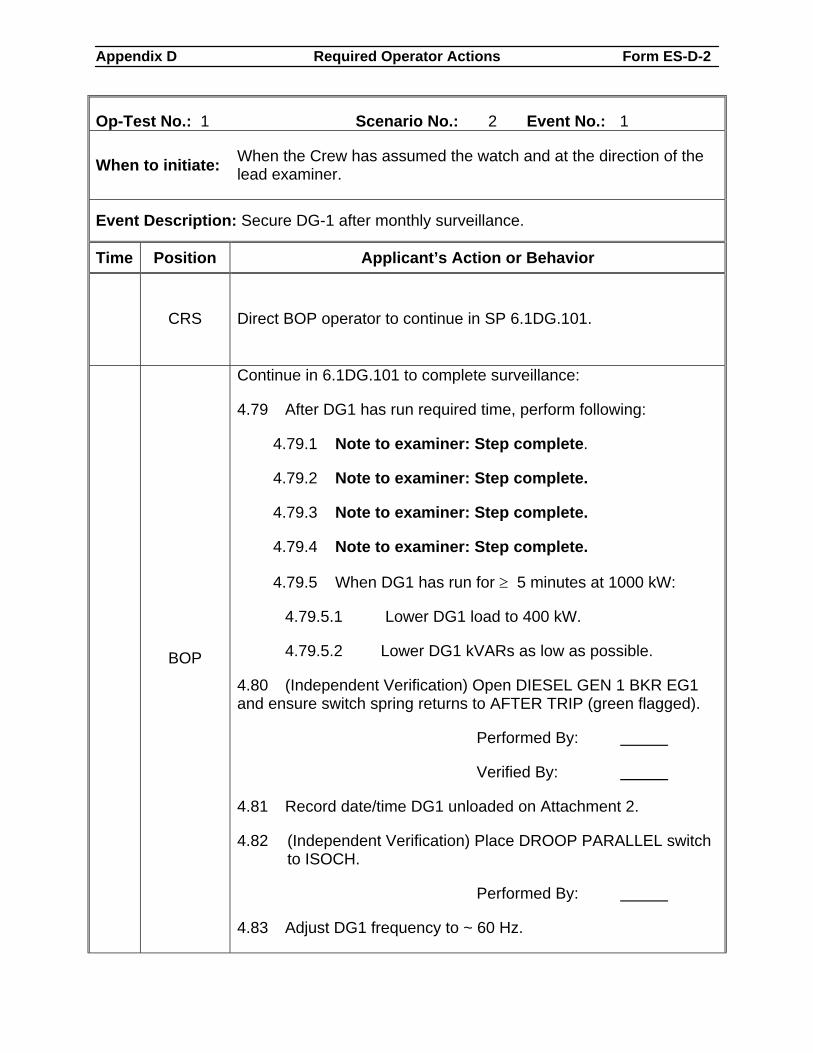
Appendix D Required Operator Actions Form ES-D-2
Op-Test No.: 1 Scenario No.: 2 Event No.: 1
When to initiate: When the Crew has assumed the watch and at the direction of the lead examiner.
Event Description: Secure DG-1 after monthly surveillance.
Time Position Applicant’s Action or Behavior
CRS Direct BOP operator to continue in SP 6.1DG.101.
BOP
Continue in 6.1DG.101 to complete surveillance:
4.79 After DG1 has run required time, perform following:
4.79.1 Note to examiner: Step complete.
4.79.2 Note to examiner: Step complete.
4.79.3 Note to examiner: Step complete.
4.79.4 Note to examiner: Step complete.
4.79.5 When DG1 has run for ≥ 5 minutes at 1000 kW:
4.79.5.1 Lower DG1 load to 400 kW.
4.79.5.2 Lower DG1 kVARs as low as possible.
4.80 (Independent Verification) Open DIESEL GEN 1 BKR EG1 and ensure switch spring returns to AFTER TRIP (green flagged).
Performed By:
Verified By:
4.81 Record date/time DG1 unloaded on Attachment 2.
4.82 (Independent Verification) Place DROOP PARALLEL switch to ISOCH.
Performed By:
4.83 Adjust DG1 frequency to ~ 60 Hz.
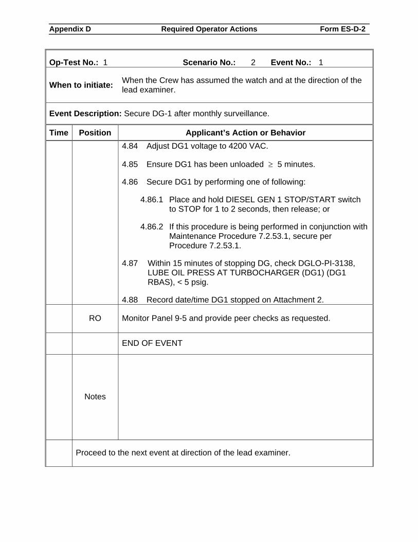
Appendix D Required Operator Actions Form ES-D-2
Op-Test No.: 1 Scenario No.: 2 Event No.: 1
When to initiate: When the Crew has assumed the watch and at the direction of the lead examiner.
Event Description: Secure DG-1 after monthly surveillance.
Time Position Applicant’s Action or Behavior 4.84 Adjust DG1 voltage to 4200 VAC.
4.85 Ensure DG1 has been unloaded ≥ 5 minutes.
4.86 Secure DG1 by performing one of following:
4.86.1 Place and hold DIESEL GEN 1 STOP/START switch to STOP for 1 to 2 seconds, then release; or
4.86.2 If this procedure is being performed in conjunction with Maintenance Procedure 7.2.53.1, secure per Procedure 7.2.53.1.
4.87 Within 15 minutes of stopping DG, check DGLO-PI-3138, LUBE OIL PRESS AT TURBOCHARGER (DG1) (DG1 RBAS), < 5 psig.
4.88 Record date/time DG1 stopped on Attachment 2.
RO Monitor Panel 9-5 and provide peer checks as requested.
END OF EVENT
Notes
Proceed to the next event at direction of the lead examiner.
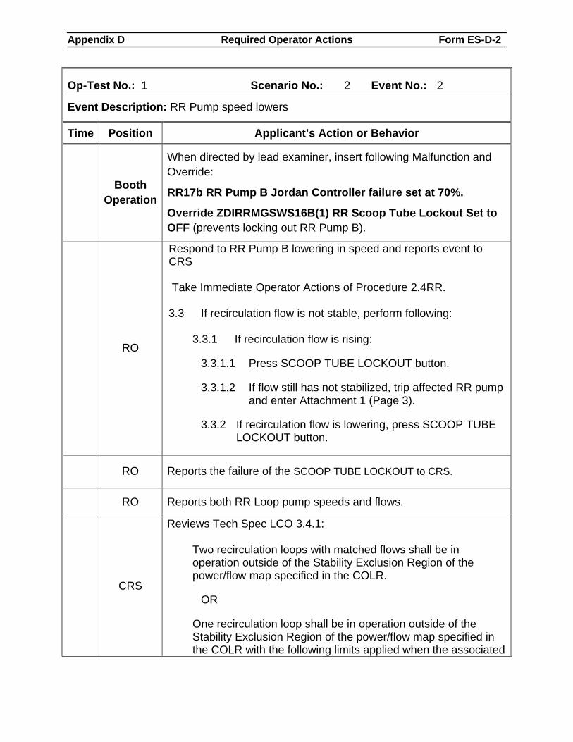
Appendix D Required Operator Actions Form ES-D-2
Op-Test No.: 1 Scenario No.: 2 Event No.: 2
Event Description: RR Pump speed lowers
Time Position Applicant’s Action or Behavior
Booth Operation
When directed by lead examiner, insert following Malfunction and Override:
RR17b RR Pump B Jordan Controller failure set at 70%.
Override ZDIRRMGSWS16B(1) RR Scoop Tube Lockout Set to OFF (prevents locking out RR Pump B).
RO
Respond to RR Pump B lowering in speed and reports event to CRS Take Immediate Operator Actions of Procedure 2.4RR. 3.3 If recirculation flow is not stable, perform following:
3.3.1 If recirculation flow is rising:
3.3.1.1 Press SCOOP TUBE LOCKOUT button.
3.3.1.2 If flow still has not stabilized, trip affected RR pump and enter Attachment 1 (Page 3).
3.3.2 If recirculation flow is lowering, press SCOOP TUBE LOCKOUT button.
RO Reports the failure of the SCOOP TUBE LOCKOUT to CRS.
RO Reports both RR Loop pump speeds and flows.
CRS
Reviews Tech Spec LCO 3.4.1:
Two recirculation loops with matched flows shall be in operation outside of the Stability Exclusion Region of the power/flow map specified in the COLR.
OR
One recirculation loop shall be in operation outside of the Stability Exclusion Region of the power/flow map specified in the COLR with the following limits applied when the associated
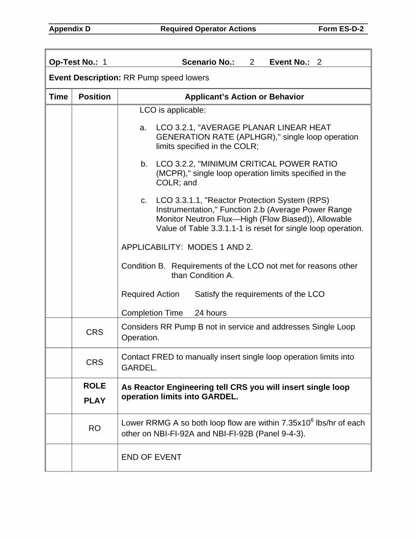
Appendix D Required Operator Actions Form ES-D-2
Op-Test No.: 1 Scenario No.: 2 Event No.: 2
Event Description: RR Pump speed lowers
Time Position Applicant’s Action or Behavior LCO is applicable:
a. LCO 3.2.1, "AVERAGE PLANAR LINEAR HEAT GENERATION RATE (APLHGR)," single loop operation limits specified in the COLR;
b. LCO 3.2.2, "MINIMUM CRITICAL POWER RATIO (MCPR)," single loop operation limits specified in the COLR; and
c. LCO 3.3.1.1, "Reactor Protection System (RPS) Instrumentation," Function 2.b (Average Power Range Monitor Neutron Flux—High (Flow Biased)), Allowable Value of Table 3.3.1.1-1 is reset for single loop operation.
APPLICABILITY: MODES 1 AND 2. Condition B. Requirements of the LCO not met for reasons other
than Condition A. Required Action Satisfy the requirements of the LCO Completion Time 24 hours
CRS Considers RR Pump B not in service and addresses Single Loop Operation.
CRS Contact FRED to manually insert single loop operation limits into GARDEL.
ROLE
PLAY As Reactor Engineering tell CRS you will insert single loop operation limits into GARDEL.
RO Lower RRMG A so both loop flow are within 7.35x10⁶ lbs/hr of each other on NBI-FI-92A and NBI-FI-92B (Panel 9-4-3).
END OF EVENT
Appendix D Required Operator Actions Form ES-D-2
Op-Test No.: 1 Scenario No.: 2 Event No.: 2
Event Description: RR Pump speed lowers
Time Position Applicant’s Action or Behavior
Notes
Proceed to the next event at direction of the lead examiner.
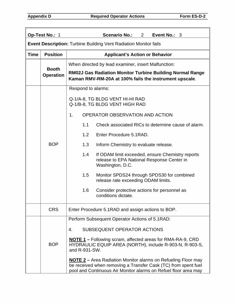
Appendix D Required Operator Actions Form ES-D-2
Op-Test No.: 1 Scenario No.: 2 Event No.: 3
Event Description: Turbine Building Vent Radiation Monitor fails
Time Position Applicant’s Action or Behavior
Booth Operation
When directed by lead examiner, insert Malfunction:
RM02J Gas Radiation Monitor Turbine Building Normal Range Kaman RMV-RM-20A at 100% fails the instrument upscale.
BOP
Respond to alarms: Q-1/A-8, TG BLDG VENT HI-HI RAD Q-1/B-8, TG BLDG VENT HIGH RAD 1. OPERATOR OBSERVATION AND ACTION
1.1 Check associated RICs to determine cause of alarm.
1.2 Enter Procedure 5.1RAD.
1.3 Inform Chemistry to evaluate release.
1.4 If ODAM limit exceeded, ensure Chemistry reports release to EPA National Response Center in Washington, D.C.
1.5 Monitor SPDS24 through SPDS30 for combined release rate exceeding ODAM limits.
1.6 Consider protective actions for personnel as conditions dictate.
CRS Enter Procedure 5.1RAD and assign actions to BOP.
BOP
Perform Subsequent Operator Actions of 5.1RAD: 4. SUBSEQUENT OPERATOR ACTIONS
NOTE 1 – Following scram, affected areas for RMA-RA-9, CRD HYDRAULIC EQUIP AREA (NORTH), include R-903-N, R-903-S, and R-931-SW.
NOTE 2 – Area Radiation Monitor alarms on Refueling Floor may be received when removing a Transfer Cask (TC) from spent fuel pool and Continuous Air Monitor alarms on Refuel floor area may
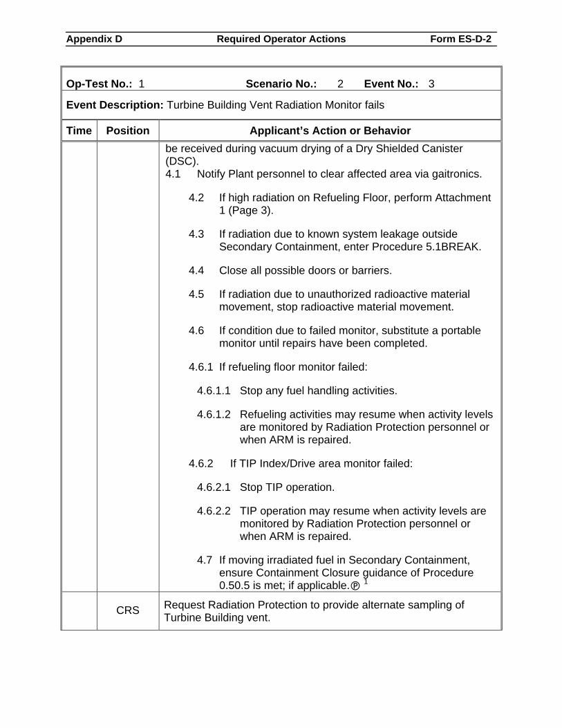
Appendix D Required Operator Actions Form ES-D-2
Op-Test No.: 1 Scenario No.: 2 Event No.: 3
Event Description: Turbine Building Vent Radiation Monitor fails
Time Position Applicant’s Action or Behavior be received during vacuum drying of a Dry Shielded Canister (DSC). 4.1 Notify Plant personnel to clear affected area via gaitronics.
4.2 If high radiation on Refueling Floor, perform Attachment 1 (Page 3).
4.3 If radiation due to known system leakage outside Secondary Containment, enter Procedure 5.1BREAK.
4.4 Close all possible doors or barriers.
4.5 If radiation due to unauthorized radioactive material movement, stop radioactive material movement.
4.6 If condition due to failed monitor, substitute a portable monitor until repairs have been completed.
4.6.1 If refueling floor monitor failed:
4.6.1.1 Stop any fuel handling activities.
4.6.1.2 Refueling activities may resume when activity levels are monitored by Radiation Protection personnel or when ARM is repaired.
4.6.2 If TIP Index/Drive area monitor failed:
4.6.2.1 Stop TIP operation.
4.6.2.2 TIP operation may resume when activity levels are monitored by Radiation Protection personnel or when ARM is repaired.
4.7 If moving irradiated fuel in Secondary Containment, ensure Containment Closure guidance of Procedure 0.50.5 is met; if applicable. 1
CRS Request Radiation Protection to provide alternate sampling of Turbine Building vent.
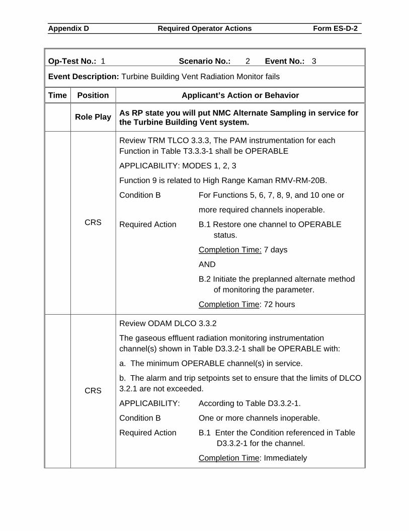
Appendix D Required Operator Actions Form ES-D-2
Op-Test No.: 1 Scenario No.: 2 Event No.: 3
Event Description: Turbine Building Vent Radiation Monitor fails
Time Position Applicant’s Action or Behavior
Role Play As RP state you will put NMC Alternate Sampling in service for the Turbine Building Vent system.
CRS
Review TRM TLCO 3.3.3, The PAM instrumentation for each Function in Table T3.3.3-1 shall be OPERABLE
APPLICABILITY: MODES 1, 2, 3
Function 9 is related to High Range Kaman RMV-RM-20B.
Condition B For Functions 5, 6, 7, 8, 9, and 10 one or
more required channels inoperable.
Required Action B.1 Restore one channel to OPERABLE status.
Completion Time: 7 days
AND
B.2 Initiate the preplanned alternate method of monitoring the parameter.
Completion Time: 72 hours
CRS
Review ODAM DLCO 3.3.2
The gaseous effluent radiation monitoring instrumentation channel(s) shown in Table D3.3.2-1 shall be OPERABLE with:
a. The minimum OPERABLE channel(s) in service.
b. The alarm and trip setpoints set to ensure that the limits of DLCO 3.2.1 are not exceeded.
APPLICABILITY: According to Table D3.3.2-1.
Condition B One or more channels inoperable.
Required Action B.1 Enter the Condition referenced in Table D3.3.2-1 for the channel.
Completion Time: Immediately
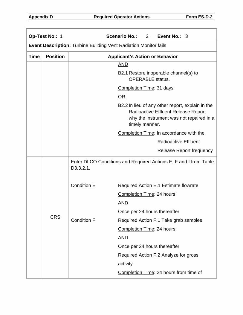
Appendix D Required Operator Actions Form ES-D-2
Op-Test No.: 1 Scenario No.: 2 Event No.: 3
Event Description: Turbine Building Vent Radiation Monitor fails
Time Position Applicant’s Action or Behavior AND
B2.1 Restore inoperable channel(s) to OPERABLE status.
Completion Time: 31 days
OR
B2.2 In lieu of any other report, explain in the Radioactive Effluent Release Report why the instrument was not repaired in a timely manner.
Completion Time: In accordance with the
Radioactive Effluent
Release Report frequency
CRS
Enter DLCO Conditions and Required Actions E, F and I from Table D3.3.2.1.
Condition E Required Action E.1 Estimate flowrate
Completion Time: 24 hours
AND
Once per 24 hours thereafter
Condition F Required Action F.1 Take grab samples
Completion Time: 24 hours
AND
Once per 24 hours thereafter
Required Action F.2 Analyze for gross
activity.
Completion Time: 24 hours from time of
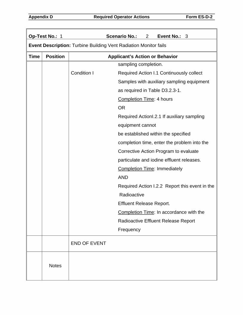
Appendix D Required Operator Actions Form ES-D-2
Op-Test No.: 1 Scenario No.: 2 Event No.: 3
Event Description: Turbine Building Vent Radiation Monitor fails
Time Position Applicant’s Action or Behavior sampling completion.
Condition I Required Action I.1 Continuously collect
Samples with auxiliary sampling equipment
as required in Table D3.2.3-1.
Completion Time: 4 hours
OR
Required ActionI.2.1 If auxiliary sampling
equipment cannot
be established within the specified
completion time, enter the problem into the
Corrective Action Program to evaluate
particulate and iodine effluent releases.
Completion Time: Immediately
AND
Required Action I.2.2 Report this event in the
Radioactive
Effluent Release Report.
Completion Time: In accordance with the
Radioactive Effluent Release Report
Frequency
END OF EVENT
Notes
Appendix D Required Operator Actions Form ES-D-2
Op-Test No.: 1 Scenario No.: 2 Event No.: 3
Event Description: Turbine Building Vent Radiation Monitor fails
Time Position Applicant’s Action or Behavior
Proceed to the next event at direction of the lead examiner.
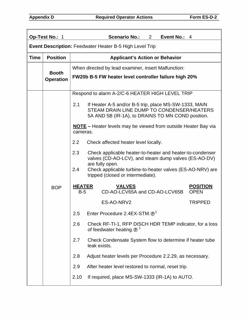
Appendix D Required Operator Actions Form ES-D-2
Op-Test No.: 1 Scenario No.: 2 Event No.: 4
Event Description: Feedwater Heater B-5 High Level Trip
Time Position Applicant’s Action or Behavior
Booth Operation
When directed by lead examiner, insert Malfunction:
FW20b B-5 FW heater level controller failure high 20%
BOP
Respond to alarm A-2/C-6 HEATER HIGH LEVEL TRIP 2.1 If Heater A-5 and/or B-5 trip, place MS-SW-1333, MAIN
STEAM DRAIN LINE DUMP TO CONDENSER/HEATERS 5A AND 5B (IR-1A), to DRAINS TO MN COND position.
NOTE – Heater levels may be viewed from outside Heater Bay via cameras.
2.2 Check affected heater level locally.
2.3 Check applicable heater-to-heater and heater-to-condenser valves (CD-AO-LCV), and steam dump valves (ES-AO-DV) are fully open.
2.4 Check applicable turbine-to-heater valves (ES-AO-NRV) are tripped (closed or intermediate).
HEATER VALVES POSITION
B-5 CD-AO-LCV65A and CD-AO-LCV65B OPEN
ES-AO-NRV2 TRIPPED 2.5 Enter Procedure 2.4EX-STM. 1
2.6 Check RF-TI-1, RFP DISCH HDR TEMP indicator, for a loss of feedwater heating. 1
2.7 Check Condensate System flow to determine if heater tube leak exists.
2.8 Adjust heater levels per Procedure 2.2.29, as necessary.
2.9 After heater level restored to normal, reset trip.
2.10 If required, place MS-SW-1333 (IR-1A) to AUTO.
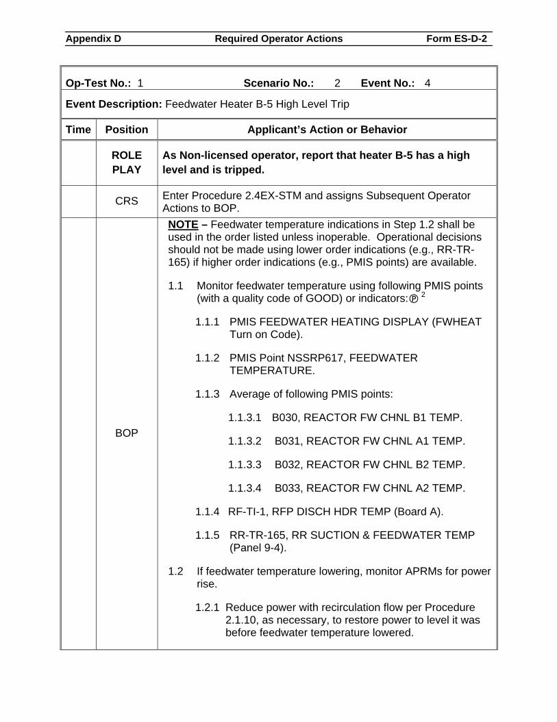
Appendix D Required Operator Actions Form ES-D-2
Op-Test No.: 1 Scenario No.: 2 Event No.: 4
Event Description: Feedwater Heater B-5 High Level Trip
Time Position Applicant’s Action or Behavior
ROLE PLAY
As Non-licensed operator, report that heater B-5 has a high level and is tripped.
CRS Enter Procedure 2.4EX-STM and assigns Subsequent Operator Actions to BOP.
BOP
NOTE – Feedwater temperature indications in Step 1.2 shall be used in the order listed unless inoperable. Operational decisions should not be made using lower order indications (e.g., RR-TR-165) if higher order indications (e.g., PMIS points) are available.
1.1 Monitor feedwater temperature using following PMIS points (with a quality code of GOOD) or indicators: 2
1.1.1 PMIS FEEDWATER HEATING DISPLAY (FWHEAT Turn on Code).
1.1.2 PMIS Point NSSRP617, FEEDWATER TEMPERATURE.
1.1.3 Average of following PMIS points:
1.1.3.1 B030, REACTOR FW CHNL B1 TEMP.
1.1.3.2 B031, REACTOR FW CHNL A1 TEMP.
1.1.3.3 B032, REACTOR FW CHNL B2 TEMP.
1.1.3.4 B033, REACTOR FW CHNL A2 TEMP.
1.1.4 RF-TI-1, RFP DISCH HDR TEMP (Board A).
1.1.5 RR-TR-165, RR SUCTION & FEEDWATER TEMP (Panel 9-4).
1.2 If feedwater temperature lowering, monitor APRMs for power rise.
1.2.1 Reduce power with recirculation flow per Procedure 2.1.10, as necessary, to restore power to level it was before feedwater temperature lowered.
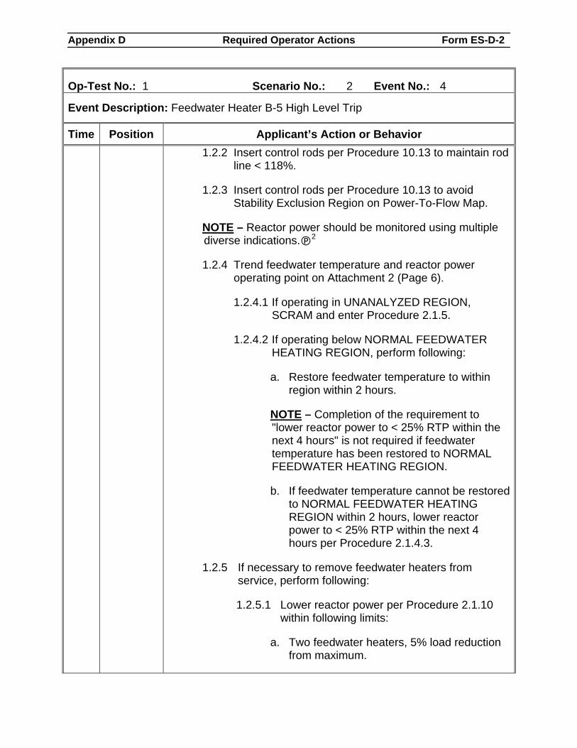
Appendix D Required Operator Actions Form ES-D-2
Op-Test No.: 1 Scenario No.: 2 Event No.: 4
Event Description: Feedwater Heater B-5 High Level Trip
Time Position Applicant’s Action or Behavior 1.2.2 Insert control rods per Procedure 10.13 to maintain rod
line < 118%.
1.2.3 Insert control rods per Procedure 10.13 to avoid Stability Exclusion Region on Power-To-Flow Map.
NOTE – Reactor power should be monitored using multiple diverse indications. 2
1.2.4 Trend feedwater temperature and reactor power operating point on Attachment 2 (Page 6).
1.2.4.1 If operating in UNANALYZED REGION, SCRAM and enter Procedure 2.1.5.
1.2.4.2 If operating below NORMAL FEEDWATER HEATING REGION, perform following:
a. Restore feedwater temperature to within region within 2 hours.
NOTE – Completion of the requirement to "lower reactor power to < 25% RTP within the next 4 hours" is not required if feedwater temperature has been restored to NORMAL FEEDWATER HEATING REGION.
b. If feedwater temperature cannot be restored to NORMAL FEEDWATER HEATING REGION within 2 hours, lower reactor power to < 25% RTP within the next 4 hours per Procedure 2.1.4.3.
1.2.5 If necessary to remove feedwater heaters from service, perform following:
1.2.5.1 Lower reactor power per Procedure 2.1.10 within following limits:
a. Two feedwater heaters, 5% load reduction from maximum.
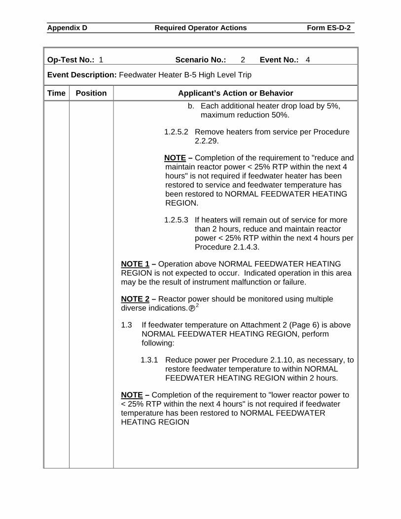
Appendix D Required Operator Actions Form ES-D-2
Op-Test No.: 1 Scenario No.: 2 Event No.: 4
Event Description: Feedwater Heater B-5 High Level Trip
Time Position Applicant’s Action or Behavior b. Each additional heater drop load by 5%,
maximum reduction 50%.
1.2.5.2 Remove heaters from service per Procedure 2.2.29.
NOTE – Completion of the requirement to "reduce and maintain reactor power < 25% RTP within the next 4 hours" is not required if feedwater heater has been restored to service and feedwater temperature has been restored to NORMAL FEEDWATER HEATING REGION.
1.2.5.3 If heaters will remain out of service for more than 2 hours, reduce and maintain reactor power < 25% RTP within the next 4 hours per Procedure 2.1.4.3.
NOTE 1 – Operation above NORMAL FEEDWATER HEATING REGION is not expected to occur. Indicated operation in this area may be the result of instrument malfunction or failure.
NOTE 2 – Reactor power should be monitored using multiple diverse indications. 2
1.3 If feedwater temperature on Attachment 2 (Page 6) is above NORMAL FEEDWATER HEATING REGION, perform following:
1.3.1 Reduce power per Procedure 2.1.10, as necessary, to restore feedwater temperature to within NORMAL FEEDWATER HEATING REGION within 2 hours.
NOTE – Completion of the requirement to "lower reactor power to < 25% RTP within the next 4 hours" is not required if feedwater temperature has been restored to NORMAL FEEDWATER HEATING REGION
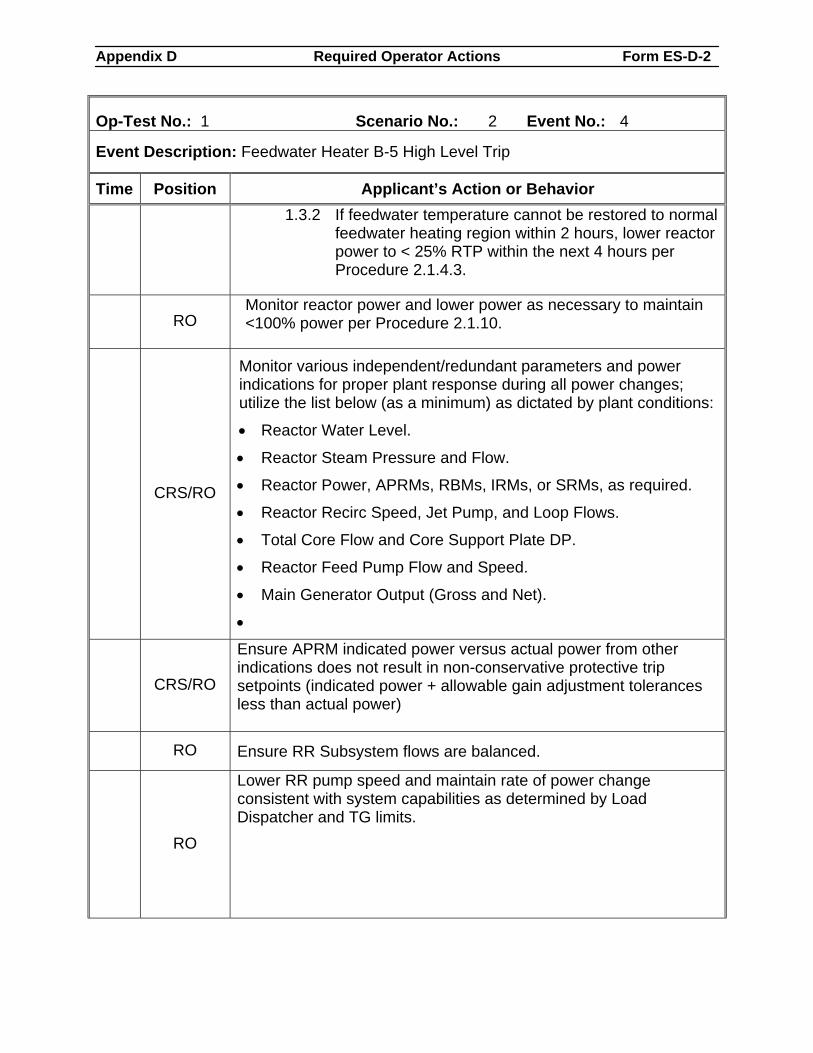
Appendix D Required Operator Actions Form ES-D-2
Op-Test No.: 1 Scenario No.: 2 Event No.: 4
Event Description: Feedwater Heater B-5 High Level Trip
Time Position Applicant’s Action or Behavior 1.3.2 If feedwater temperature cannot be restored to normal
feedwater heating region within 2 hours, lower reactor power to < 25% RTP within the next 4 hours per Procedure 2.1.4.3.
RO Monitor reactor power and lower power as necessary to maintain <100% power per Procedure 2.1.10.
CRS/RO
Monitor various independent/redundant parameters and power indications for proper plant response during all power changes; utilize the list below (as a minimum) as dictated by plant conditions:
• Reactor Water Level.
• Reactor Steam Pressure and Flow.
• Reactor Power, APRMs, RBMs, IRMs, or SRMs, as required.
• Reactor Recirc Speed, Jet Pump, and Loop Flows.
• Total Core Flow and Core Support Plate DP.
• Reactor Feed Pump Flow and Speed.
• Main Generator Output (Gross and Net).
•
CRS/RO
Ensure APRM indicated power versus actual power from other indications does not result in non-conservative protective trip setpoints (indicated power + allowable gain adjustment tolerances less than actual power)
RO Ensure RR Subsystem flows are balanced.
RO
Lower RR pump speed and maintain rate of power change consistent with system capabilities as determined by Load Dispatcher and TG limits.
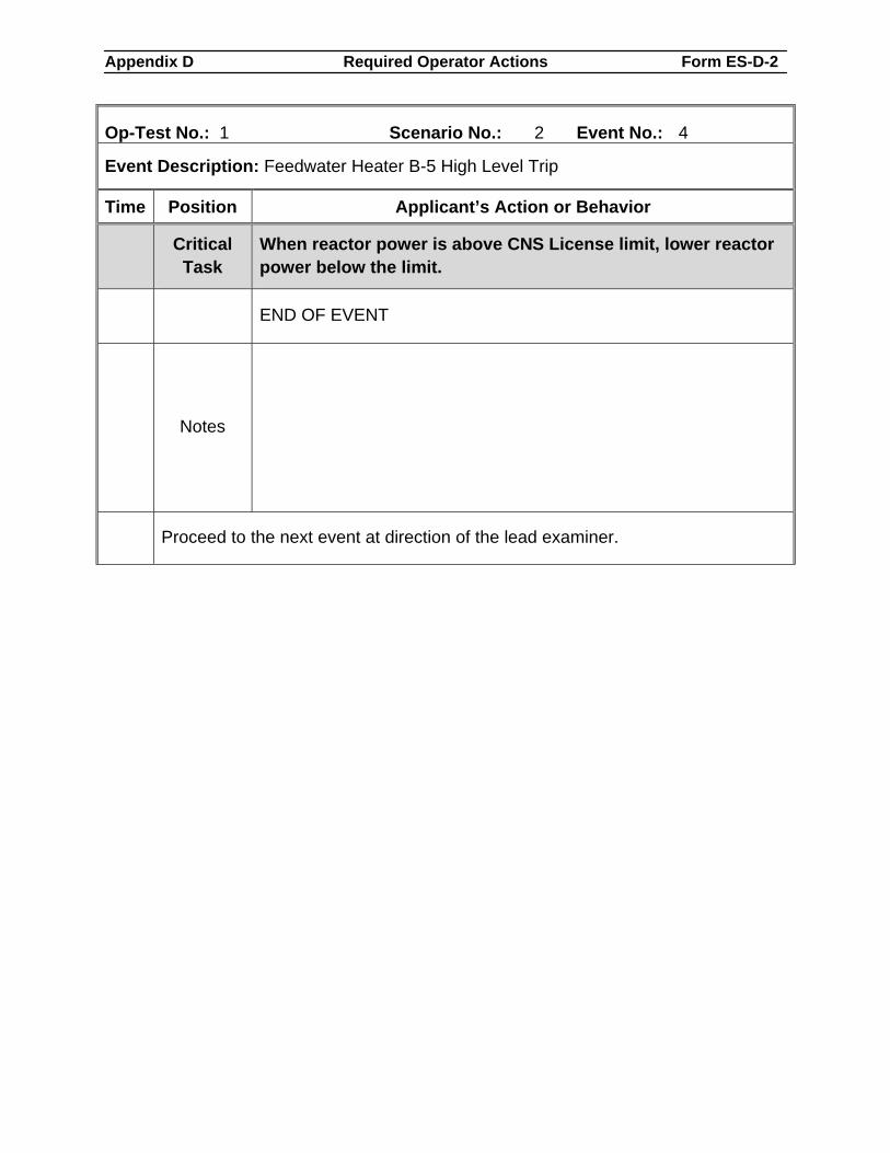
Appendix D Required Operator Actions Form ES-D-2
Op-Test No.: 1 Scenario No.: 2 Event No.: 4
Event Description: Feedwater Heater B-5 High Level Trip
Time Position Applicant’s Action or Behavior
Critical Task
When reactor power is above CNS License limit, lower reactor power below the limit.
END OF EVENT
Notes
Proceed to the next event at direction of the lead examiner.
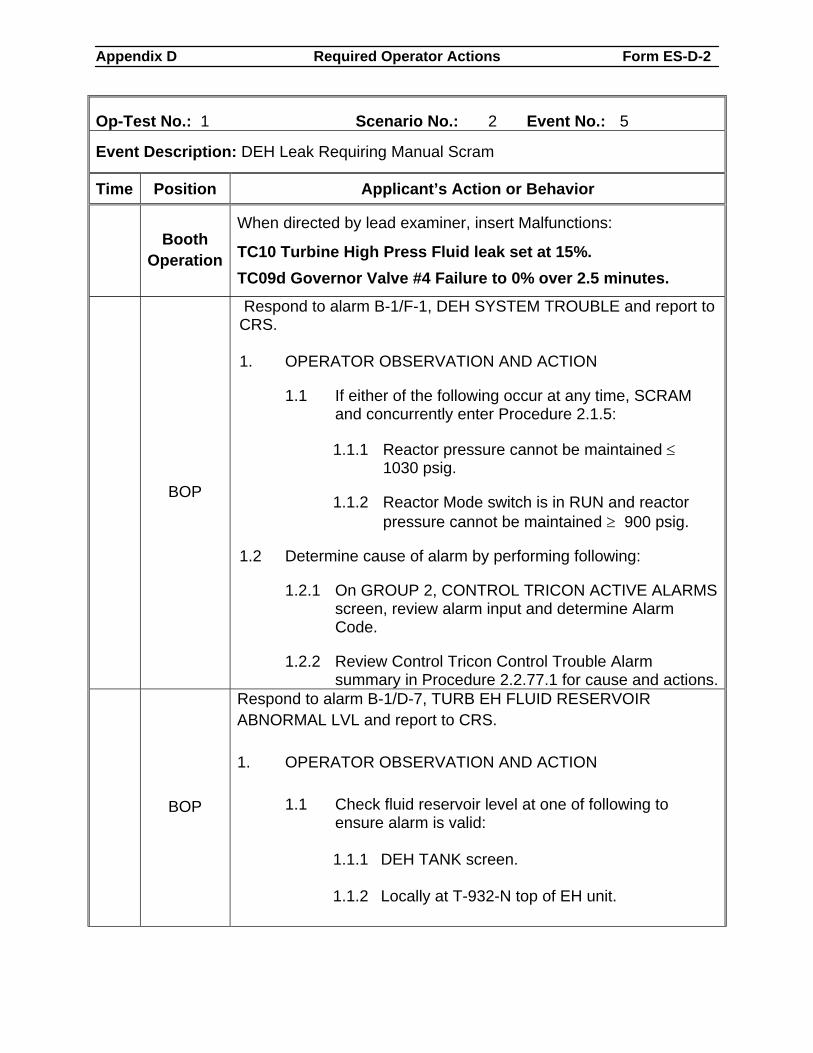
Appendix D Required Operator Actions Form ES-D-2
Op-Test No.: 1 Scenario No.: 2 Event No.: 5
Event Description: DEH Leak Requiring Manual Scram
Time Position Applicant’s Action or Behavior
Booth Operation
When directed by lead examiner, insert Malfunctions:
TC10 Turbine High Press Fluid leak set at 15%. TC09d Governor Valve #4 Failure to 0% over 2.5 minutes.
BOP
Respond to alarm B-1/F-1, DEH SYSTEM TROUBLE and report to CRS. 1. OPERATOR OBSERVATION AND ACTION
1.1 If either of the following occur at any time, SCRAM and concurrently enter Procedure 2.1.5:
1.1.1 Reactor pressure cannot be maintained ≤ 1030 psig.
1.1.2 Reactor Mode switch is in RUN and reactor pressure cannot be maintained ≥ 900 psig.
1.2 Determine cause of alarm by performing following:
1.2.1 On GROUP 2, CONTROL TRICON ACTIVE ALARMS screen, review alarm input and determine Alarm Code.
1.2.2 Review Control Tricon Control Trouble Alarm summary in Procedure 2.2.77.1 for cause and actions.
BOP
Respond to alarm B-1/D-7, TURB EH FLUID RESERVOIR ABNORMAL LVL and report to CRS. 1. OPERATOR OBSERVATION AND ACTION
1.1 Check fluid reservoir level at one of following to ensure alarm is valid:
1.1.1 DEH TANK screen. 1.1.2 Locally at T-932-N top of EH unit.
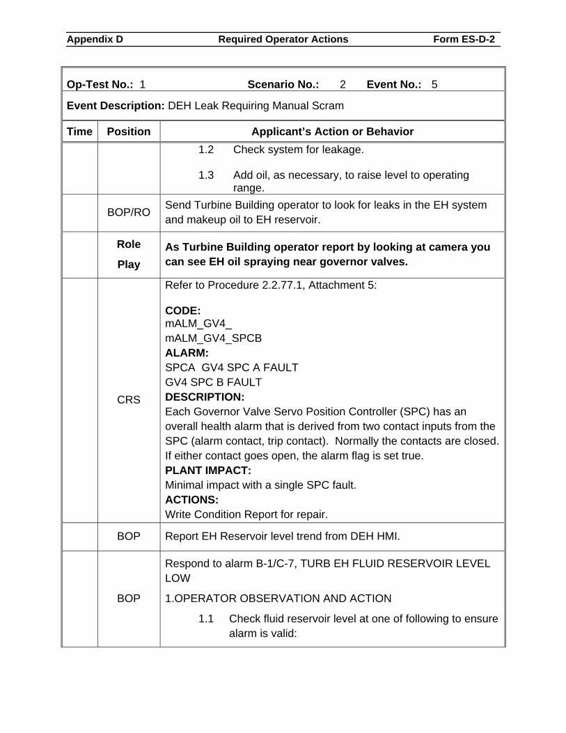
Appendix D Required Operator Actions Form ES-D-2
Op-Test No.: 1 Scenario No.: 2 Event No.: 5
Event Description: DEH Leak Requiring Manual Scram
Time Position Applicant’s Action or Behavior
1.2 Check system for leakage. 1.3 Add oil, as necessary, to raise level to operating
range.
BOP/RO Send Turbine Building operator to look for leaks in the EH system and makeup oil to EH reservoir.
Role
Play As Turbine Building operator report by looking at camera you can see EH oil spraying near governor valves.
CRS
Refer to Procedure 2.2.77.1, Attachment 5: CODE: mALM_GV4_ mALM_GV4_SPCB ALARM: SPCA GV4 SPC A FAULT GV4 SPC B FAULT DESCRIPTION: Each Governor Valve Servo Position Controller (SPC) has an overall health alarm that is derived from two contact inputs from the SPC (alarm contact, trip contact). Normally the contacts are closed. If either contact goes open, the alarm flag is set true. PLANT IMPACT: Minimal impact with a single SPC fault. ACTIONS: Write Condition Report for repair.
BOP Report EH Reservoir level trend from DEH HMI.
BOP
Respond to alarm B-1/C-7, TURB EH FLUID RESERVOIR LEVEL LOW
1.OPERATOR OBSERVATION AND ACTION
1.1 Check fluid reservoir level at one of following to ensure alarm is valid:
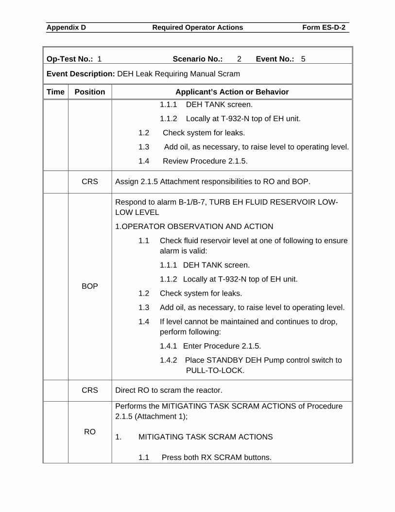
Appendix D Required Operator Actions Form ES-D-2
Op-Test No.: 1 Scenario No.: 2 Event No.: 5
Event Description: DEH Leak Requiring Manual Scram
Time Position Applicant’s Action or Behavior 1.1.1 DEH TANK screen.
1.1.2 Locally at T-932-N top of EH unit.
1.2 Check system for leaks.
1.3 Add oil, as necessary, to raise level to operating level.
1.4 Review Procedure 2.1.5.
CRS Assign 2.1.5 Attachment responsibilities to RO and BOP.
BOP
Respond to alarm B-1/B-7, TURB EH FLUID RESERVOIR LOW-LOW LEVEL
1.OPERATOR OBSERVATION AND ACTION
1.1 Check fluid reservoir level at one of following to ensure alarm is valid:
1.1.1 DEH TANK screen.
1.1.2 Locally at T-932-N top of EH unit.
1.2 Check system for leaks.
1.3 Add oil, as necessary, to raise level to operating level.
1.4 If level cannot be maintained and continues to drop, perform following:
1.4.1 Enter Procedure 2.1.5.
1.4.2 Place STANDBY DEH Pump control switch to PULL-TO-LOCK.
CRS Direct RO to scram the reactor.
RO
Performs the MITIGATING TASK SCRAM ACTIONS of Procedure 2.1.5 (Attachment 1); 1. MITIGATING TASK SCRAM ACTIONS
1.1 Press both RX SCRAM buttons.
Appendix D Required Operator Actions Form ES-D-2
Op-Test No.: 1 Scenario No.: 2 Event No.: 5
Event Description: DEH Leak Requiring Manual Scram
Time Position Applicant’s Action or Behavior 1.2 Place REACTOR MODE switch to REFUEL.
1.3 Announce reactor scram and reactor status to Control Room including controlling systems for critical parameters.
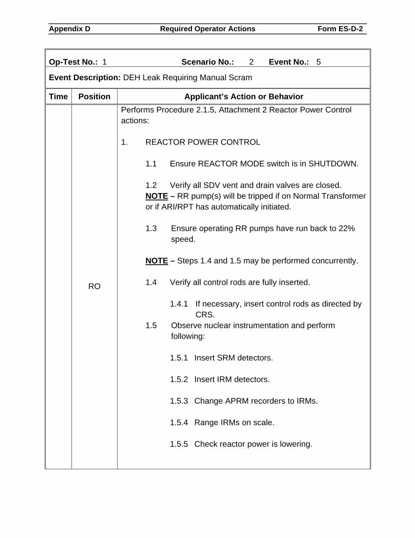
Appendix D Required Operator Actions Form ES-D-2
Op-Test No.: 1 Scenario No.: 2 Event No.: 5
Event Description: DEH Leak Requiring Manual Scram
Time Position Applicant’s Action or Behavior
RO
Performs Procedure 2.1.5, Attachment 2 Reactor Power Control actions: 1. REACTOR POWER CONTROL
1.1 Ensure REACTOR MODE switch is in SHUTDOWN. 1.2 Verify all SDV vent and drain valves are closed. NOTE – RR pump(s) will be tripped if on Normal Transformer or if ARI/RPT has automatically initiated.
1.3 Ensure operating RR pumps have run back to 22%
speed. NOTE – Steps 1.4 and 1.5 may be performed concurrently.
1.4 Verify all control rods are fully inserted.
1.4.1 If necessary, insert control rods as directed by CRS.
1.5 Observe nuclear instrumentation and perform following:
1.5.1 Insert SRM detectors. 1.5.2 Insert IRM detectors. 1.5.3 Change APRM recorders to IRMs. 1.5.4 Range IRMs on scale. 1.5.5 Check reactor power is lowering.
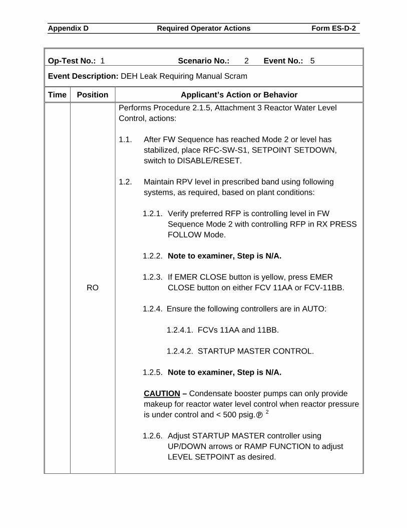
Appendix D Required Operator Actions Form ES-D-2
Op-Test No.: 1 Scenario No.: 2 Event No.: 5
Event Description: DEH Leak Requiring Manual Scram
Time Position Applicant’s Action or Behavior
RO
Performs Procedure 2.1.5, Attachment 3 Reactor Water Level Control, actions: 1.1. After FW Sequence has reached Mode 2 or level has
stabilized, place RFC-SW-S1, SETPOINT SETDOWN, switch to DISABLE/RESET.
1.2. Maintain RPV level in prescribed band using following
systems, as required, based on plant conditions:
1.2.1. Verify preferred RFP is controlling level in FW Sequence Mode 2 with controlling RFP in RX PRESS FOLLOW Mode.
1.2.2. Note to examiner, Step is N/A.
1.2.3. If EMER CLOSE button is yellow, press EMER
CLOSE button on either FCV 11AA or FCV-11BB. 1.2.4. Ensure the following controllers are in AUTO:
1.2.4.1. FCVs 11AA and 11BB.
1.2.4.2. STARTUP MASTER CONTROL.
1.2.5. Note to examiner, Step is N/A.
CAUTION – Condensate booster pumps can only provide
makeup for reactor water level control when reactor pressure is under control and < 500 psig. 2
1.2.6. Adjust STARTUP MASTER controller using
UP/DOWN arrows or RAMP FUNCTION to adjust LEVEL SETPOINT as desired.
Appendix D Required Operator Actions Form ES-D-2
Op-Test No.: 1 Scenario No.: 2 Event No.: 5
Event Description: DEH Leak Requiring Manual Scram
Time Position Applicant’s Action or Behavior 1.2.7. HPCI per Procedure 2.2.33.1.
1.2.8. RCIC per Procedure 2.2.67.1.
1.3. Trip non-preferred RFP, if not needed, or minimum flow is
isolated. 1.4. Trip all but one condensate booster pump. 1.5. Trip all but one condensate pump.
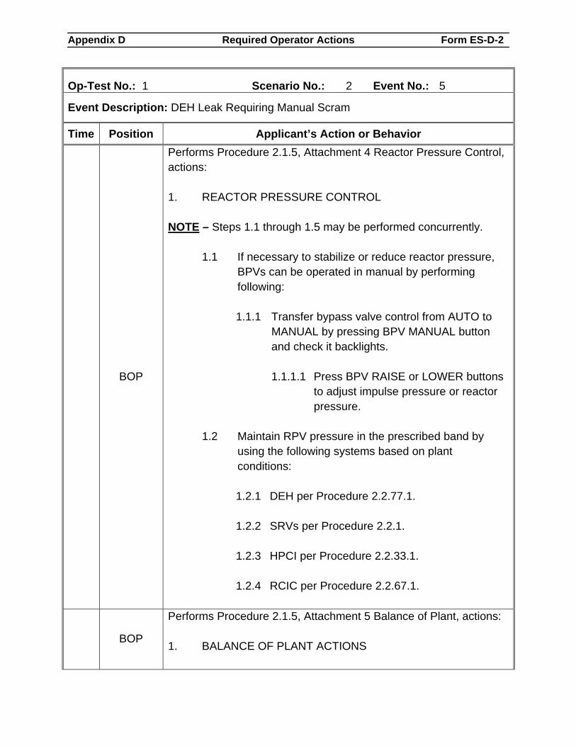
Appendix D Required Operator Actions Form ES-D-2
Op-Test No.: 1 Scenario No.: 2 Event No.: 5
Event Description: DEH Leak Requiring Manual Scram
Time Position Applicant’s Action or Behavior
BOP
Performs Procedure 2.1.5, Attachment 4 Reactor Pressure Control, actions: 1. REACTOR PRESSURE CONTROL NOTE – Steps 1.1 through 1.5 may be performed concurrently.
1.1 If necessary to stabilize or reduce reactor pressure, BPVs can be operated in manual by performing following:
1.1.1 Transfer bypass valve control from AUTO to
MANUAL by pressing BPV MANUAL button and check it backlights.
1.1.1.1 Press BPV RAISE or LOWER buttons
to adjust impulse pressure or reactor pressure.
1.2 Maintain RPV pressure in the prescribed band by
using the following systems based on plant conditions:
1.2.1 DEH per Procedure 2.2.77.1.
1.2.2 SRVs per Procedure 2.2.1.
1.2.3 HPCI per Procedure 2.2.33.1.
1.2.4 RCIC per Procedure 2.2.67.1.
BOP
Performs Procedure 2.1.5, Attachment 5 Balance of Plant, actions: 1. BALANCE OF PLANT ACTIONS
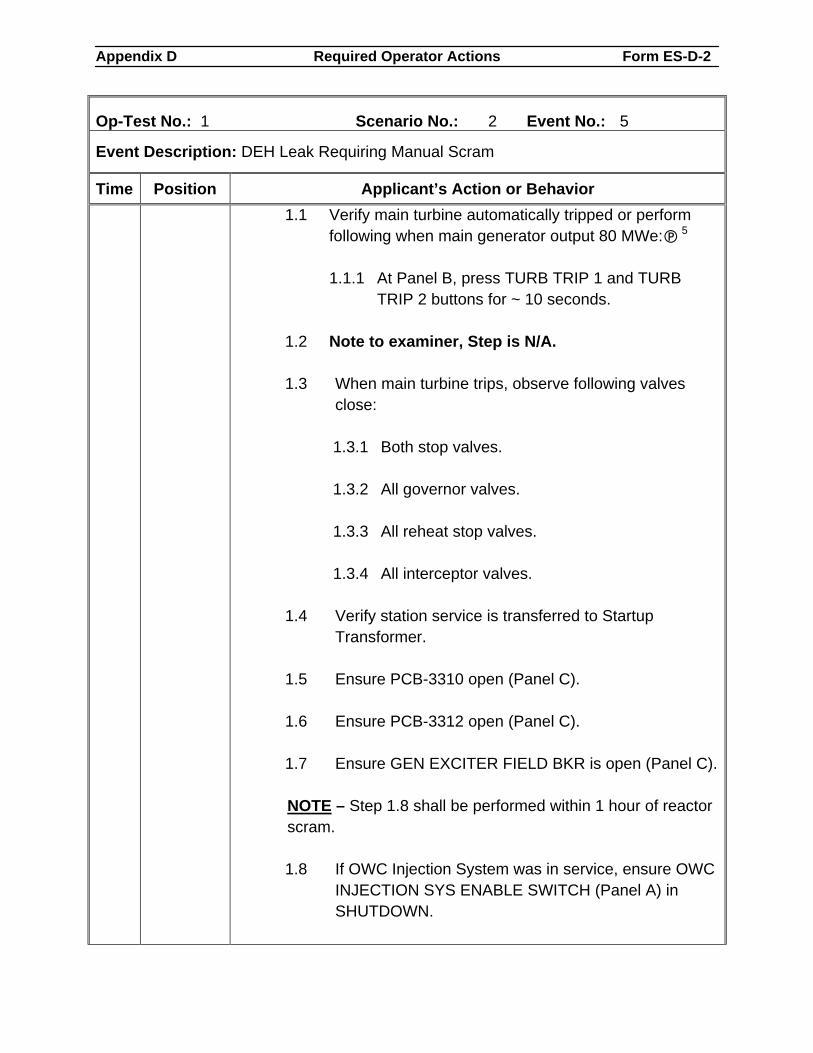
Appendix D Required Operator Actions Form ES-D-2
Op-Test No.: 1 Scenario No.: 2 Event No.: 5
Event Description: DEH Leak Requiring Manual Scram
Time Position Applicant’s Action or Behavior 1.1 Verify main turbine automatically tripped or perform
following when main generator output 80 MWe: 5
1.1.1 At Panel B, press TURB TRIP 1 and TURB TRIP 2 buttons for ~ 10 seconds.
1.2 Note to examiner, Step is N/A. 1.3 When main turbine trips, observe following valves
close:
1.3.1 Both stop valves. 1.3.2 All governor valves. 1.3.3 All reheat stop valves. 1.3.4 All interceptor valves.
1.4 Verify station service is transferred to Startup
Transformer. 1.5 Ensure PCB-3310 open (Panel C). 1.6 Ensure PCB-3312 open (Panel C). 1.7 Ensure GEN EXCITER FIELD BKR is open (Panel C).
NOTE – Step 1.8 shall be performed within 1 hour of reactor
scram.
1.8 If OWC Injection System was in service, ensure OWC INJECTION SYS ENABLE SWITCH (Panel A) in SHUTDOWN.
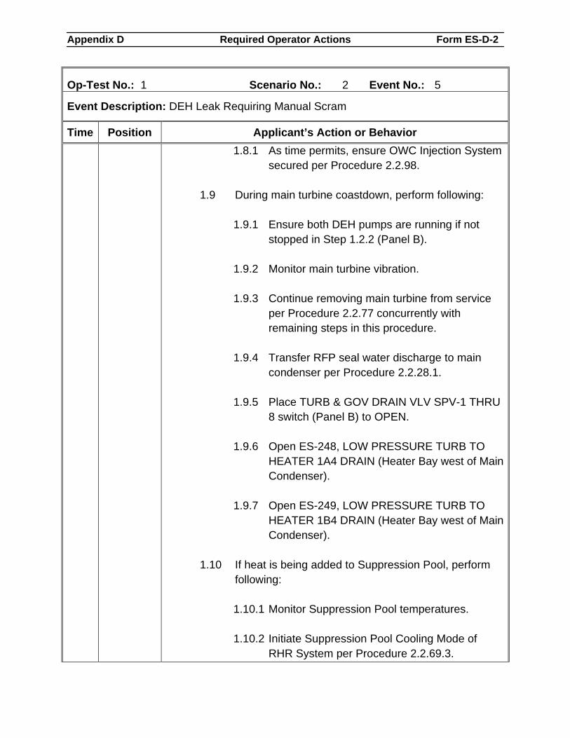
Appendix D Required Operator Actions Form ES-D-2
Op-Test No.: 1 Scenario No.: 2 Event No.: 5
Event Description: DEH Leak Requiring Manual Scram
Time Position Applicant’s Action or Behavior 1.8.1 As time permits, ensure OWC Injection System
secured per Procedure 2.2.98. 1.9 During main turbine coastdown, perform following:
1.9.1 Ensure both DEH pumps are running if not stopped in Step 1.2.2 (Panel B).
1.9.2 Monitor main turbine vibration. 1.9.3 Continue removing main turbine from service
per Procedure 2.2.77 concurrently with remaining steps in this procedure.
1.9.4 Transfer RFP seal water discharge to main
condenser per Procedure 2.2.28.1. 1.9.5 Place TURB & GOV DRAIN VLV SPV-1 THRU
8 switch (Panel B) to OPEN. 1.9.6 Open ES-248, LOW PRESSURE TURB TO
HEATER 1A4 DRAIN (Heater Bay west of Main Condenser).
1.9.7 Open ES-249, LOW PRESSURE TURB TO
HEATER 1B4 DRAIN (Heater Bay west of Main Condenser).
1.10 If heat is being added to Suppression Pool, perform
following:
1.10.1 Monitor Suppression Pool temperatures. 1.10.2 Initiate Suppression Pool Cooling Mode of
RHR System per Procedure 2.2.69.3.
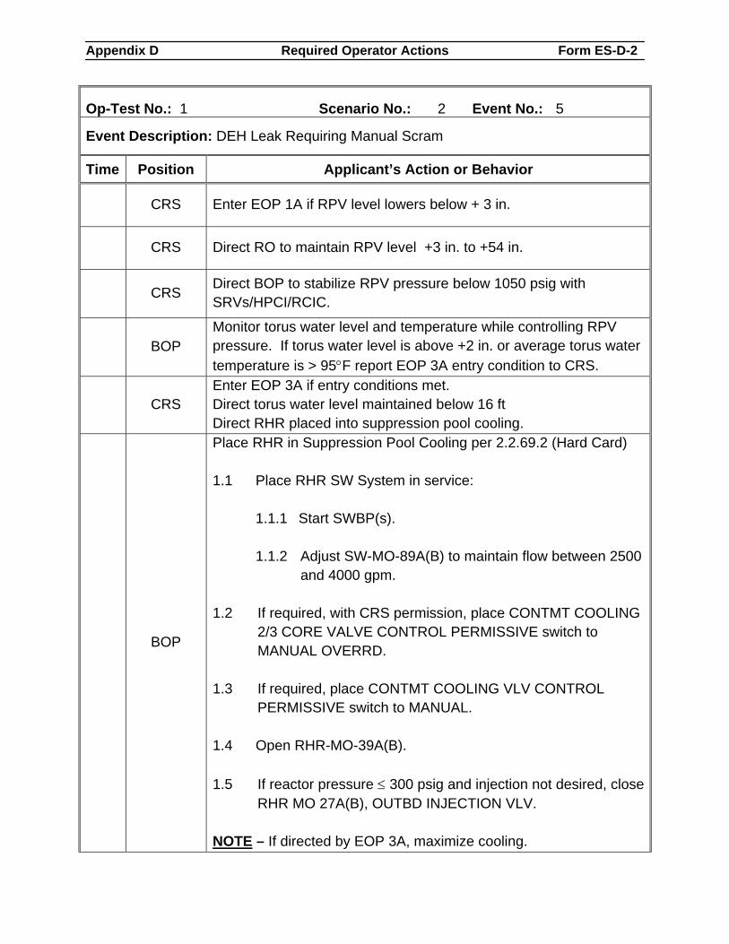
Appendix D Required Operator Actions Form ES-D-2
Op-Test No.: 1 Scenario No.: 2 Event No.: 5
Event Description: DEH Leak Requiring Manual Scram
Time Position Applicant’s Action or Behavior
CRS Enter EOP 1A if RPV level lowers below + 3 in.
CRS Direct RO to maintain RPV level +3 in. to +54 in.
CRS Direct BOP to stabilize RPV pressure below 1050 psig with SRVs/HPCI/RCIC.
BOP
Monitor torus water level and temperature while controlling RPV pressure. If torus water level is above +2 in. or average torus water temperature is > 95°F report EOP 3A entry condition to CRS.
CRS
Enter EOP 3A if entry conditions met. Direct torus water level maintained below 16 ft Direct RHR placed into suppression pool cooling.
BOP
Place RHR in Suppression Pool Cooling per 2.2.69.2 (Hard Card) 1.1 Place RHR SW System in service:
1.1.1 Start SWBP(s).
1.1.2 Adjust SW-MO-89A(B) to maintain flow between 2500 and 4000 gpm.
1.2 If required, with CRS permission, place CONTMT COOLING
2/3 CORE VALVE CONTROL PERMISSIVE switch to MANUAL OVERRD.
1.3 If required, place CONTMT COOLING VLV CONTROL
PERMISSIVE switch to MANUAL. 1.4 Open RHR-MO-39A(B). 1.5 If reactor pressure ≤ 300 psig and injection not desired, close
RHR MO 27A(B), OUTBD INJECTION VLV. NOTE – If directed by EOP 3A, maximize cooling.
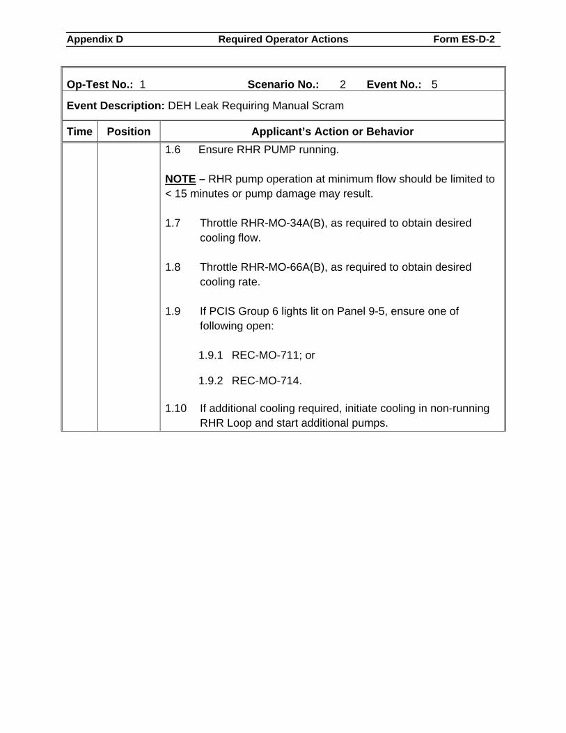
Appendix D Required Operator Actions Form ES-D-2
Op-Test No.: 1 Scenario No.: 2 Event No.: 5
Event Description: DEH Leak Requiring Manual Scram
Time Position Applicant’s Action or Behavior 1.6 Ensure RHR PUMP running. NOTE – RHR pump operation at minimum flow should be limited to < 15 minutes or pump damage may result. 1.7 Throttle RHR-MO-34A(B), as required to obtain desired
cooling flow. 1.8 Throttle RHR-MO-66A(B), as required to obtain desired
cooling rate. 1.9 If PCIS Group 6 lights lit on Panel 9-5, ensure one of
following open:
1.9.1 REC-MO-711; or 1.9.2 REC-MO-714.
1.10 If additional cooling required, initiate cooling in non-running
RHR Loop and start additional pumps.
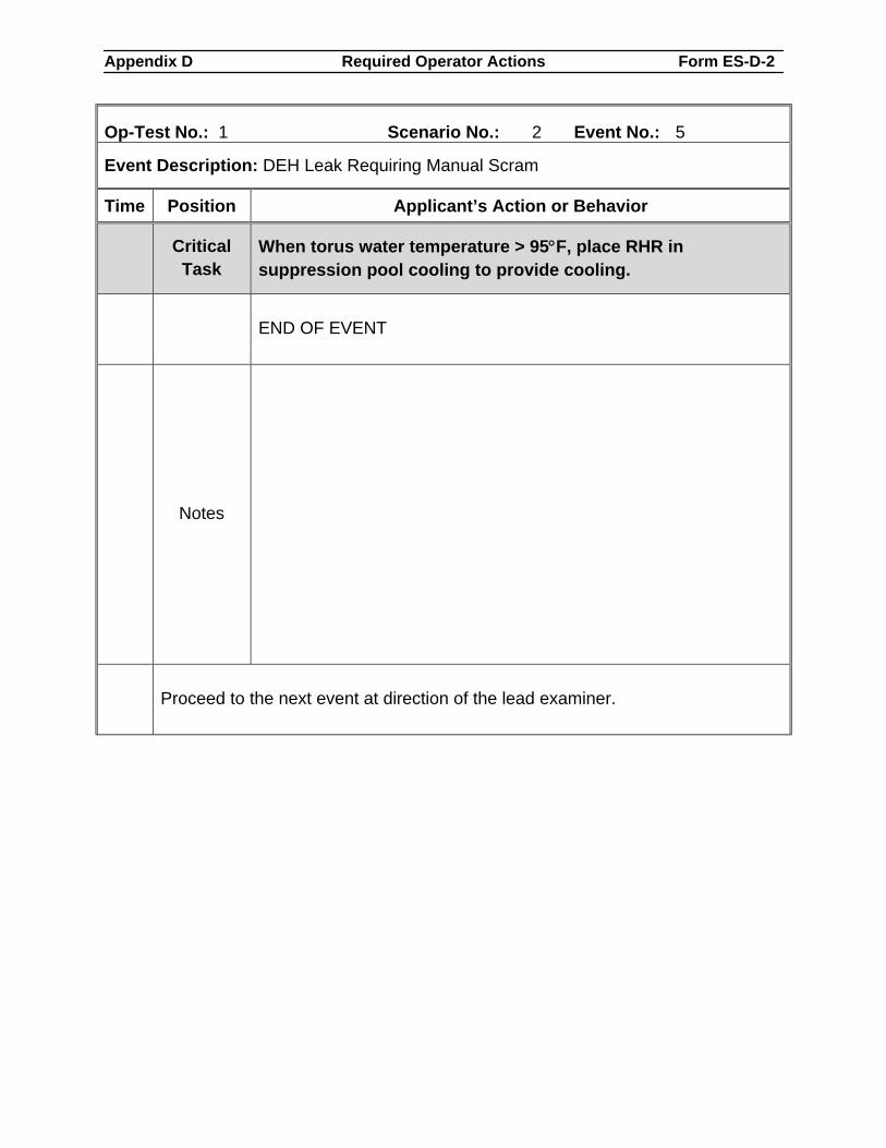
Appendix D Required Operator Actions Form ES-D-2
Op-Test No.: 1 Scenario No.: 2 Event No.: 5
Event Description: DEH Leak Requiring Manual Scram
Time Position Applicant’s Action or Behavior
Critical Task
When torus water temperature > 95°F, place RHR in suppression pool cooling to provide cooling.
END OF EVENT
Notes
Proceed to the next event at direction of the lead examiner.
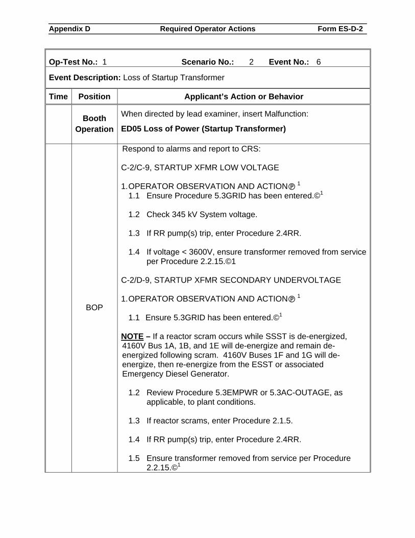
Appendix D Required Operator Actions Form ES-D-2
Op-Test No.: 1 Scenario No.: 2 Event No.: 6
Event Description: Loss of Startup Transformer
Time Position Applicant’s Action or Behavior
Booth Operation
When directed by lead examiner, insert Malfunction:
ED05 Loss of Power (Startup Transformer)
BOP
Respond to alarms and report to CRS: C-2/C-9, STARTUP XFMR LOW VOLTAGE 1. OPERATOR OBSERVATION AND ACTION 1
1.1 Ensure Procedure 5.3GRID has been entered.©1 1.2 Check 345 kV System voltage. 1.3 If RR pump(s) trip, enter Procedure 2.4RR. 1.4 If voltage < 3600V, ensure transformer removed from service
per Procedure 2.2.15.©1 C-2/D-9, STARTUP XFMR SECONDARY UNDERVOLTAGE 1. OPERATOR OBSERVATION AND ACTION 1
1.1 Ensure 5.3GRID has been entered.©1
NOTE – If a reactor scram occurs while SSST is de-energized, 4160V Bus 1A, 1B, and 1E will de-energize and remain de-energized following scram. 4160V Buses 1F and 1G will de-energize, then re-energize from the ESST or associated Emergency Diesel Generator.
1.2 Review Procedure 5.3EMPWR or 5.3AC-OUTAGE, as applicable, to plant conditions.
1.3 If reactor scrams, enter Procedure 2.1.5. 1.4 If RR pump(s) trip, enter Procedure 2.4RR. 1.5 Ensure transformer removed from service per Procedure
2.2.15.©1
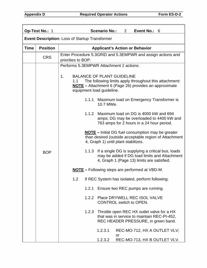
Appendix D Required Operator Actions Form ES-D-2
Op-Test No.: 1 Scenario No.: 2 Event No.: 6
Event Description: Loss of Startup Transformer
Time Position Applicant’s Action or Behavior
CRS Enter Procedure 5.3GRID and 5.3EMPWR and assign actions and priorities to BOP.
BOP
Performs 5.3EMPWR Attachment 2 actions: 1. BALANCE OF PLANT GUIDELINE
1.1 The following limits apply throughout this attachment: NOTE – Attachment 6 (Page 26) provides an approximate equipment load guideline.
1.1.1 Maximum load on Emergency Transformer is 10.7 MWe.
1.1.2 Maximum load on DG is 4000 kW and 694
amps; DG may be overloaded to 4400 kW and 763 amps for 2 hours in a 24 hour period.
NOTE – Initial DG fuel consumption may be greater than desired (outside acceptable region of Attachment 4, Graph 1) until plant stabilizes. 1.1.3 If a single DG is supplying a critical bus, loads
may be added if DG load limits and Attachment 4, Graph 1 (Page 13) limits are satisfied.
NOTE – Following steps are performed at VBD-M. 1.2 If REC System has isolated, perform following:
1.2.1 Ensure two REC pumps are running. 1.2.2 Place DRYWELL REC ISOL VALVE
CONTROL switch to OPEN. 1.2.3 Throttle open REC HX outlet valve for a HX
that was in service to maintain REC-PI-452, REC HEADER PRESSURE, in green band.
1.2.3.1 REC-MO-712, HX A OUTLET VLV;
or 1.2.3.2 REC-MO-713, HX B OUTLET VLV.
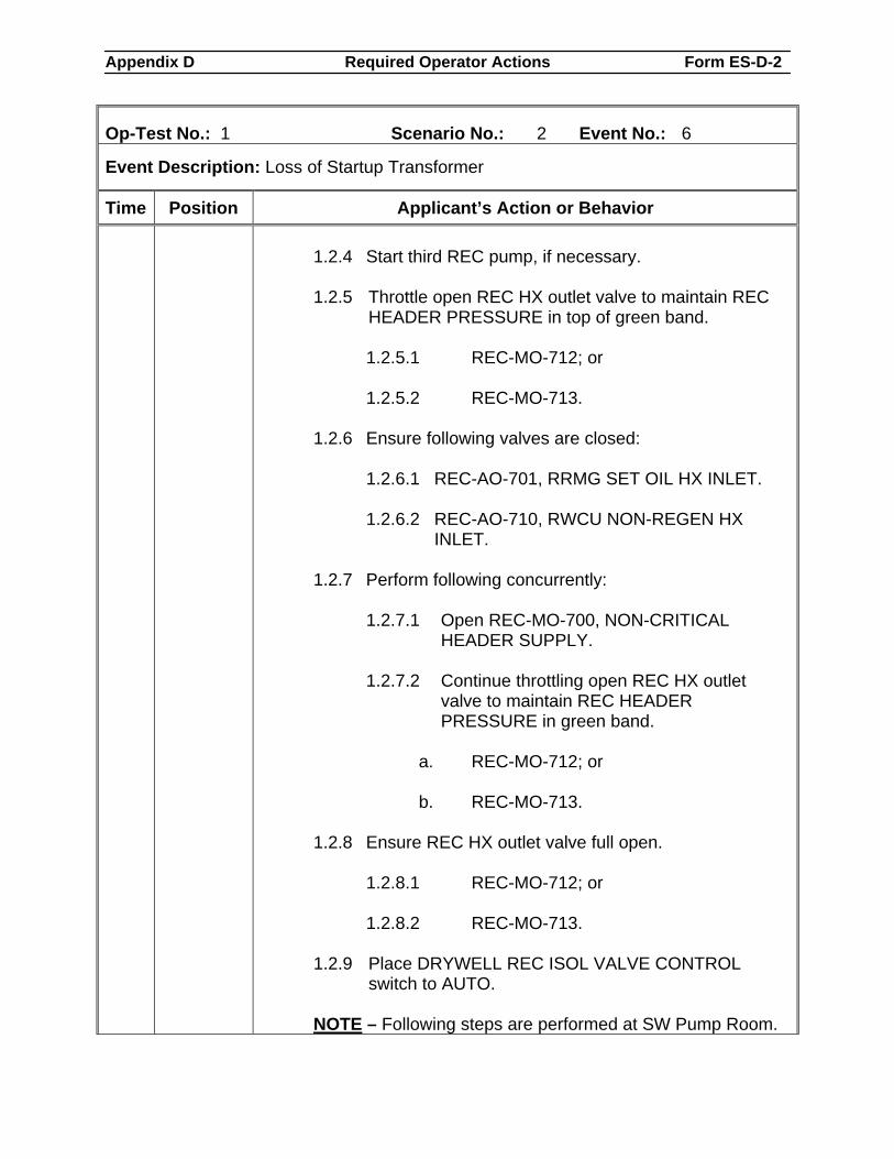
Appendix D Required Operator Actions Form ES-D-2
Op-Test No.: 1 Scenario No.: 2 Event No.: 6
Event Description: Loss of Startup Transformer
Time Position Applicant’s Action or Behavior
1.2.4 Start third REC pump, if necessary. 1.2.5 Throttle open REC HX outlet valve to maintain REC
HEADER PRESSURE in top of green band.
1.2.5.1 REC-MO-712; or 1.2.5.2 REC-MO-713.
1.2.6 Ensure following valves are closed:
1.2.6.1 REC-AO-701, RRMG SET OIL HX INLET. 1.2.6.2 REC-AO-710, RWCU NON-REGEN HX
INLET. 1.2.7 Perform following concurrently:
1.2.7.1 Open REC-MO-700, NON-CRITICAL HEADER SUPPLY.
1.2.7.2 Continue throttling open REC HX outlet
valve to maintain REC HEADER PRESSURE in green band.
a. REC-MO-712; or b. REC-MO-713.
1.2.8 Ensure REC HX outlet valve full open.
1.2.8.1 REC-MO-712; or 1.2.8.2 REC-MO-713.
1.2.9 Place DRYWELL REC ISOL VALVE CONTROL switch to AUTO.
NOTE – Following steps are performed at SW Pump Room.
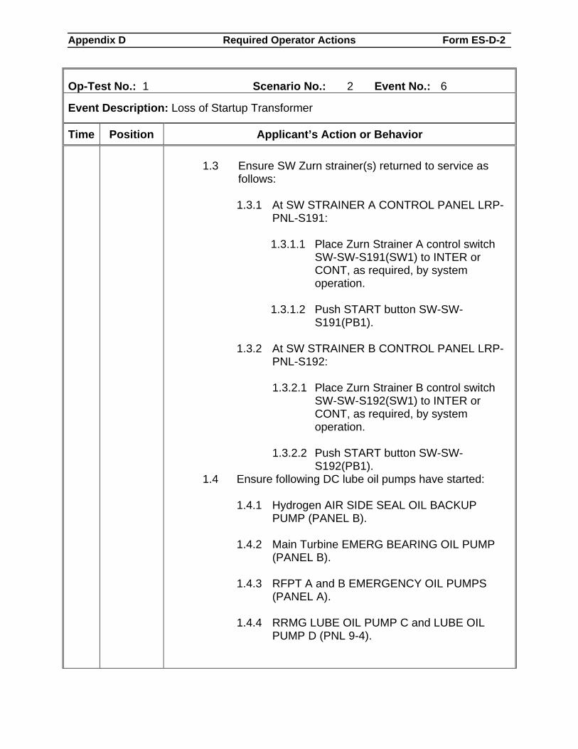
Appendix D Required Operator Actions Form ES-D-2
Op-Test No.: 1 Scenario No.: 2 Event No.: 6
Event Description: Loss of Startup Transformer
Time Position Applicant’s Action or Behavior 1.3 Ensure SW Zurn strainer(s) returned to service as
follows:
1.3.1 At SW STRAINER A CONTROL PANEL LRP-PNL-S191:
1.3.1.1 Place Zurn Strainer A control switch
SW-SW-S191(SW1) to INTER or CONT, as required, by system operation.
1.3.1.2 Push START button SW-SW-
S191(PB1).
1.3.2 At SW STRAINER B CONTROL PANEL LRP-PNL-S192: 1.3.2.1 Place Zurn Strainer B control switch
SW-SW-S192(SW1) to INTER or CONT, as required, by system operation.
1.3.2.2 Push START button SW-SW-
S192(PB1). 1.4 Ensure following DC lube oil pumps have started:
1.4.1 Hydrogen AIR SIDE SEAL OIL BACKUP PUMP (PANEL B).
1.4.2 Main Turbine EMERG BEARING OIL PUMP
(PANEL B). 1.4.3 RFPT A and B EMERGENCY OIL PUMPS
(PANEL A). 1.4.4 RRMG LUBE OIL PUMP C and LUBE OIL
PUMP D (PNL 9-4).
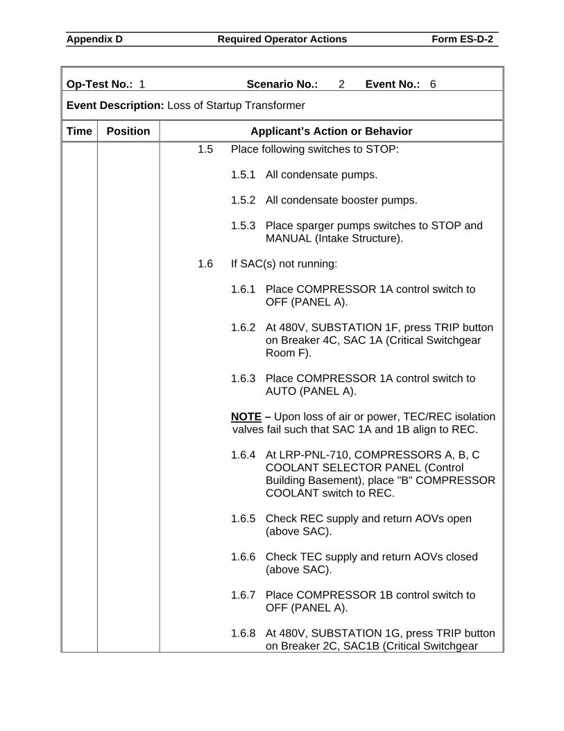
Appendix D Required Operator Actions Form ES-D-2
Op-Test No.: 1 Scenario No.: 2 Event No.: 6
Event Description: Loss of Startup Transformer
Time Position Applicant’s Action or Behavior 1.5 Place following switches to STOP:
1.5.1 All condensate pumps. 1.5.2 All condensate booster pumps. 1.5.3 Place sparger pumps switches to STOP and
MANUAL (Intake Structure).
1.6 If SAC(s) not running:
1.6.1 Place COMPRESSOR 1A control switch to OFF (PANEL A).
1.6.2 At 480V, SUBSTATION 1F, press TRIP button
on Breaker 4C, SAC 1A (Critical Switchgear Room F).
1.6.3 Place COMPRESSOR 1A control switch to
AUTO (PANEL A). NOTE – Upon loss of air or power, TEC/REC isolation valves fail such that SAC 1A and 1B align to REC. 1.6.4 At LRP-PNL-710, COMPRESSORS A, B, C
COOLANT SELECTOR PANEL (Control Building Basement), place "B" COMPRESSOR COOLANT switch to REC.
1.6.5 Check REC supply and return AOVs open
(above SAC). 1.6.6 Check TEC supply and return AOVs closed
(above SAC). 1.6.7 Place COMPRESSOR 1B control switch to
OFF (PANEL A). 1.6.8 At 480V, SUBSTATION 1G, press TRIP button
on Breaker 2C, SAC1B (Critical Switchgear
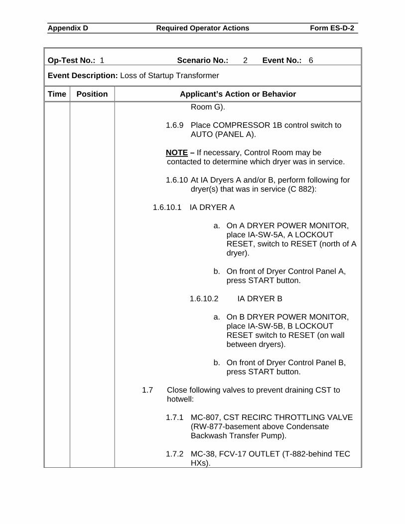
Appendix D Required Operator Actions Form ES-D-2
Op-Test No.: 1 Scenario No.: 2 Event No.: 6
Event Description: Loss of Startup Transformer
Time Position Applicant’s Action or Behavior Room G).
1.6.9 Place COMPRESSOR 1B control switch to
AUTO (PANEL A). NOTE – If necessary, Control Room may be contacted to determine which dryer was in service. 1.6.10 At IA Dryers A and/or B, perform following for
dryer(s) that was in service (C 882):
1.6.10.1 IA DRYER A
a. On A DRYER POWER MONITOR, place IA-SW-5A, A LOCKOUT RESET, switch to RESET (north of A dryer).
b. On front of Dryer Control Panel A,
press START button.
1.6.10.2 IA DRYER B
a. On B DRYER POWER MONITOR, place IA-SW-5B, B LOCKOUT RESET switch to RESET (on wall between dryers).
b. On front of Dryer Control Panel B,
press START button.
1.7 Close following valves to prevent draining CST to hotwell:
1.7.1 MC-807, CST RECIRC THROTTLING VALVE
(RW-877-basement above Condensate Backwash Transfer Pump).
1.7.2 MC-38, FCV-17 OUTLET (T-882-behind TEC
HXs).
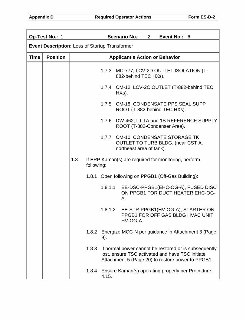
Appendix D Required Operator Actions Form ES-D-2
Op-Test No.: 1 Scenario No.: 2 Event No.: 6
Event Description: Loss of Startup Transformer
Time Position Applicant’s Action or Behavior 1.7.3 MC-777, LCV-2D OUTLET ISOLATION (T-
882-behind TEC HXs). 1.7.4 CM-12, LCV-2C OUTLET (T-882-behind TEC
HXs). 1.7.5 CM-18, CONDENSATE PPS SEAL SUPP
ROOT (T-882-behind TEC HXs). 1.7.6 DW-462, LT 1A and 1B REFERENCE SUPPLY
ROOT (T-882-Condenser Area). 1.7.7 CM-10, CONDENSATE STORAGE TK
OUTLET TO TURB BLDG. (near CST A, northeast area of tank).
1.8 If ERP Kaman(s) are required for monitoring, perform
following:
1.8.1 Open following on PPGB1 (Off-Gas Building):
1.8.1.1 EE-DSC-PPGB1(EHC-OG-A), FUSED DISC ON PPGB1 FOR DUCT HEATER EHC-OG-A.
1.8.1.2 EE-STR-PPGB1(HV-OG-A), STARTER ON
PPGB1 FOR OFF GAS BLDG HVAC UNIT HV-OG-A.
1.8.2 Energize MCC-N per guidance in Attachment 3 (Page
9). 1.8.3 If normal power cannot be restored or is subsequently
lost, ensure TSC activated and have TSC initiate Attachment 5 (Page 20) to restore power to PPGB1.
1.8.4 Ensure Kaman(s) operating properly per Procedure
4.15.
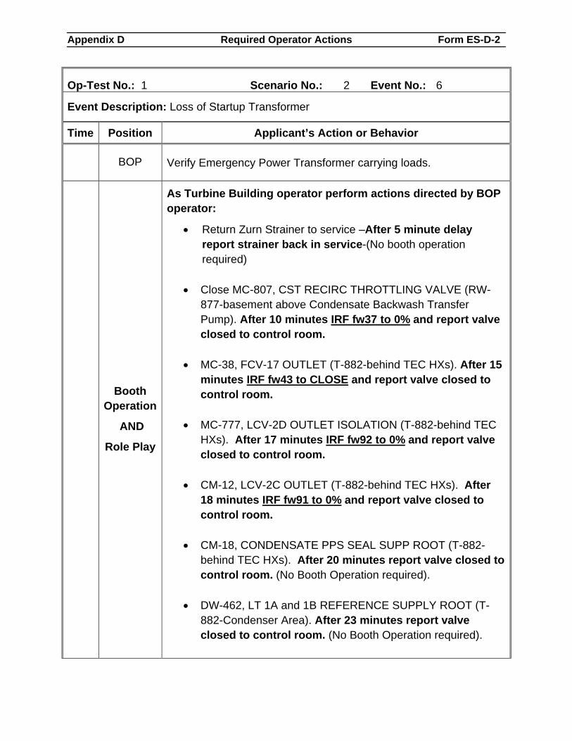
Appendix D Required Operator Actions Form ES-D-2
Op-Test No.: 1 Scenario No.: 2 Event No.: 6
Event Description: Loss of Startup Transformer
Time Position Applicant’s Action or Behavior
BOP Verify Emergency Power Transformer carrying loads.
Booth Operation
AND
Role Play
As Turbine Building operator perform actions directed by BOP operator:
• Return Zurn Strainer to service –After 5 minute delay report strainer back in service-(No booth operation required)
• Close MC-807, CST RECIRC THROTTLING VALVE (RW-877-basement above Condensate Backwash Transfer Pump). After 10 minutes IRF fw37 to 0% and report valve closed to control room.
• MC-38, FCV-17 OUTLET (T-882-behind TEC HXs). After 15
minutes IRF fw43 to CLOSE and report valve closed to control room.
• MC-777, LCV-2D OUTLET ISOLATION (T-882-behind TEC
HXs). After 17 minutes IRF fw92 to 0% and report valve closed to control room.
• CM-12, LCV-2C OUTLET (T-882-behind TEC HXs). After
18 minutes IRF fw91 to 0% and report valve closed to control room.
• CM-18, CONDENSATE PPS SEAL SUPP ROOT (T-882-
behind TEC HXs). After 20 minutes report valve closed to control room. (No Booth Operation required).
• DW-462, LT 1A and 1B REFERENCE SUPPLY ROOT (T-
882-Condenser Area). After 23 minutes report valve closed to control room. (No Booth Operation required).
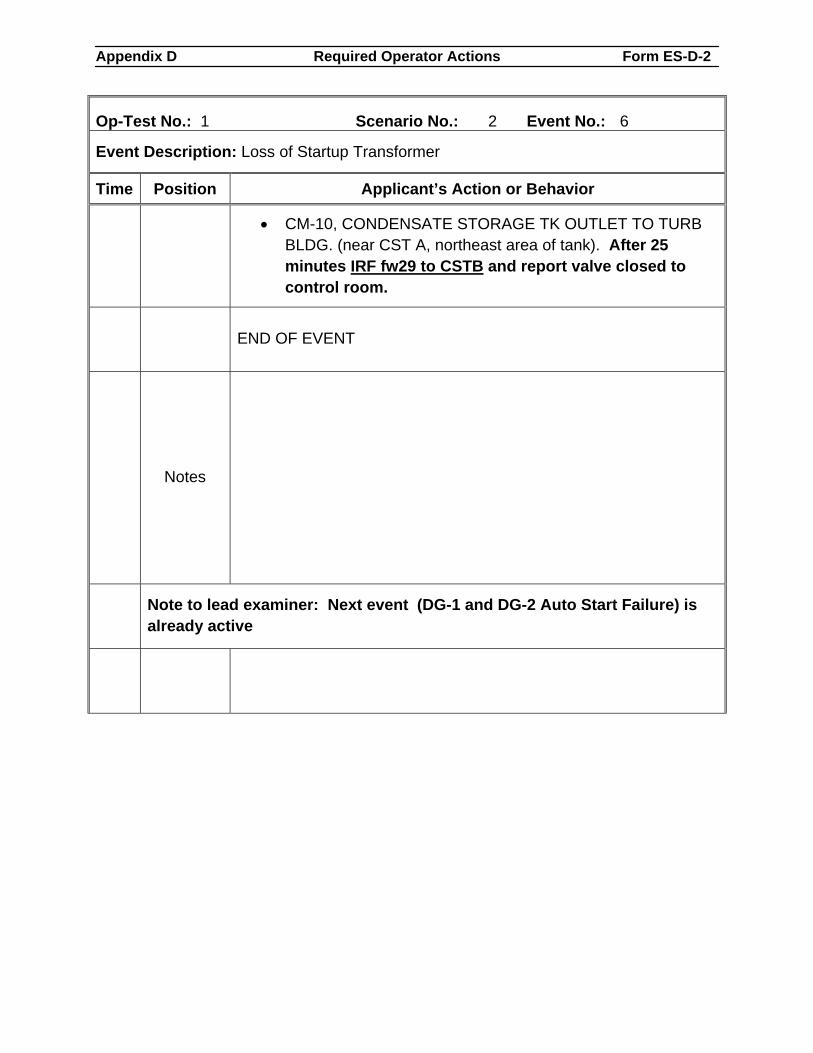
Appendix D Required Operator Actions Form ES-D-2
Op-Test No.: 1 Scenario No.: 2 Event No.: 6
Event Description: Loss of Startup Transformer
Time Position Applicant’s Action or Behavior
• CM-10, CONDENSATE STORAGE TK OUTLET TO TURB BLDG. (near CST A, northeast area of tank). After 25 minutes IRF fw29 to CSTB and report valve closed to control room.
END OF EVENT
Notes
Note to lead examiner: Next event (DG-1 and DG-2 Auto Start Failure) is already active
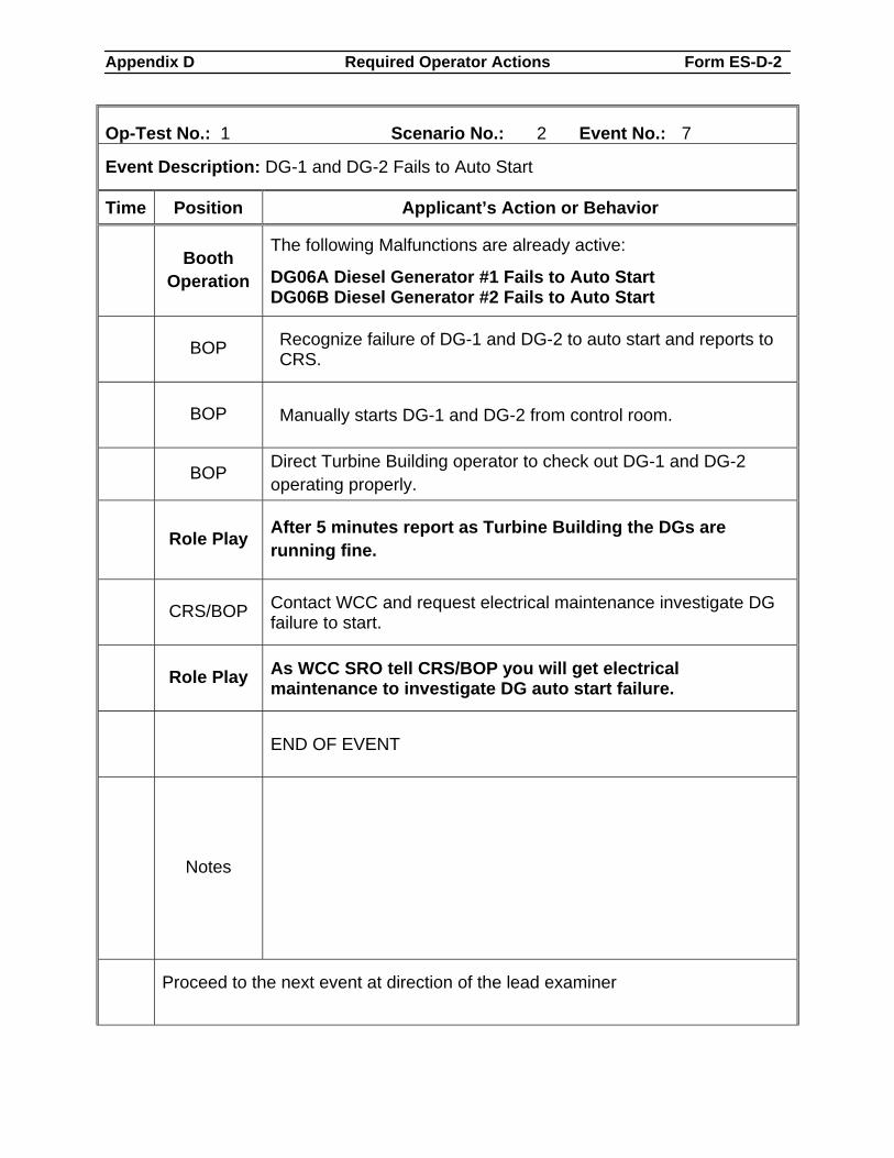
Appendix D Required Operator Actions Form ES-D-2
Op-Test No.: 1 Scenario No.: 2 Event No.: 7
Event Description: DG-1 and DG-2 Fails to Auto Start
Time Position Applicant’s Action or Behavior
Booth Operation
The following Malfunctions are already active:
DG06A Diesel Generator #1 Fails to Auto Start DG06B Diesel Generator #2 Fails to Auto Start
BOP Recognize failure of DG-1 and DG-2 to auto start and reports to CRS.
BOP Manually starts DG-1 and DG-2 from control room.
BOP Direct Turbine Building operator to check out DG-1 and DG-2 operating properly.
Role Play After 5 minutes report as Turbine Building the DGs are running fine.
CRS/BOP Contact WCC and request electrical maintenance investigate DG failure to start.
Role Play As WCC SRO tell CRS/BOP you will get electrical maintenance to investigate DG auto start failure.
END OF EVENT
Notes
Proceed to the next event at direction of the lead examiner
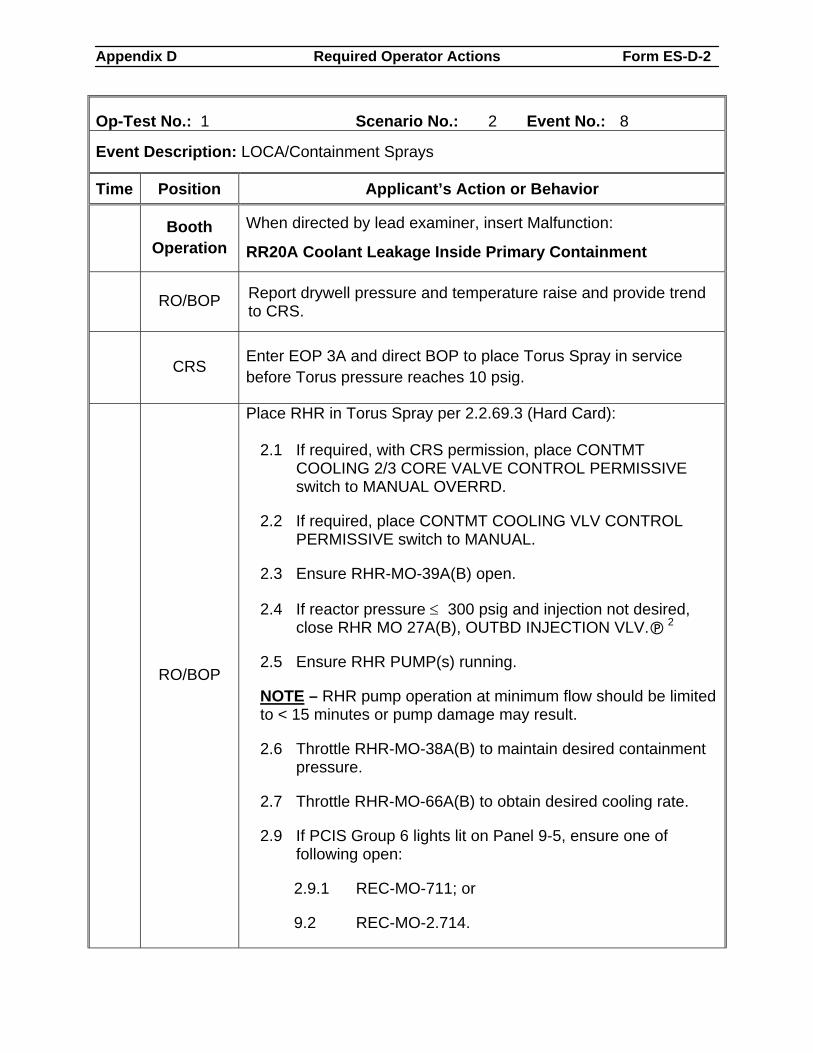
Appendix D Required Operator Actions Form ES-D-2
Op-Test No.: 1 Scenario No.: 2 Event No.: 8
Event Description: LOCA/Containment Sprays
Time Position Applicant’s Action or Behavior
Booth Operation
When directed by lead examiner, insert Malfunction:
RR20A Coolant Leakage Inside Primary Containment
RO/BOP Report drywell pressure and temperature raise and provide trend to CRS.
CRS Enter EOP 3A and direct BOP to place Torus Spray in service before Torus pressure reaches 10 psig.
RO/BOP
Place RHR in Torus Spray per 2.2.69.3 (Hard Card):
2.1 If required, with CRS permission, place CONTMT COOLING 2/3 CORE VALVE CONTROL PERMISSIVE switch to MANUAL OVERRD.
2.2 If required, place CONTMT COOLING VLV CONTROL PERMISSIVE switch to MANUAL.
2.3 Ensure RHR-MO-39A(B) open.
2.4 If reactor pressure ≤ 300 psig and injection not desired, close RHR MO 27A(B), OUTBD INJECTION VLV. 2
2.5 Ensure RHR PUMP(s) running.
NOTE – RHR pump operation at minimum flow should be limited to < 15 minutes or pump damage may result.
2.6 Throttle RHR-MO-38A(B) to maintain desired containment pressure.
2.7 Throttle RHR-MO-66A(B) to obtain desired cooling rate.
2.9 If PCIS Group 6 lights lit on Panel 9-5, ensure one of following open:
2.9.1 REC-MO-711; or
9.2 REC-MO-2.714.
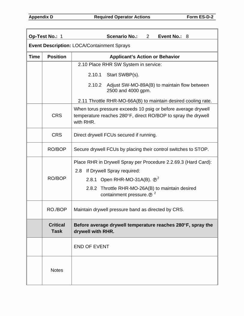
Appendix D Required Operator Actions Form ES-D-2
Op-Test No.: 1 Scenario No.: 2 Event No.: 8
Event Description: LOCA/Containment Sprays
Time Position Applicant’s Action or Behavior 2.10 Place RHR SW System in service:
2.10.1 Start SWBP(s).
2.10.2 Adjust SW-MO-89A(B) to maintain flow between 2500 and 4000 gpm.
2.11 Throttle RHR-MO-66A(B) to maintain desired cooling rate.
CRS
When torus pressure exceeds 10 psig or before average drywell temperature reaches 280°F, direct RO/BOP to spray the drywell with RHR.
CRS Direct drywell FCUs secured if running.
RO/BOP Secure drywell FCUs by placing their control switches to STOP.
RO/BOP
Place RHR in Drywell Spray per Procedure 2.2.69.3 (Hard Card):
2.8 If Drywell Spray required:
2.8.1 Open RHR-MO-31A(B). 2
2.8.2 Throttle RHR-MO-26A(B) to maintain desired containment pressure. 2
RO./BOP Maintain drywell pressure band as directed by CRS.
Critical
Task Before average drywell temperature reaches 280°F, spray the drywell with RHR.
END OF EVENT
Notes
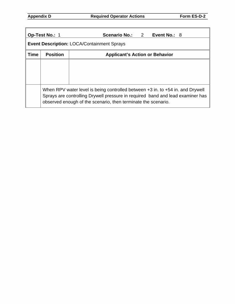
Appendix D Required Operator Actions Form ES-D-2
Op-Test No.: 1 Scenario No.: 2 Event No.: 8
Event Description: LOCA/Containment Sprays
Time Position Applicant’s Action or Behavior
When RPV water level is being controlled between +3 in. to +54 in. and Drywell Sprays are controlling Drywell pressure in required band and lead examiner has observed enough of the scenario, then terminate the scenario.
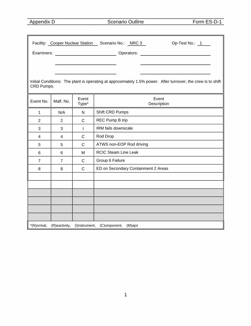
Appendix D Scenario Outline Form ES-D-1
1
Facility: Cooper Nuclear Station Scenario No.: NRC 3 Op-Test No.: 1 Examiners: Operators:
Initial Conditions: The plant is operating at approximately 1.5% power. After turnover, the crew is to shift CRD Pumps.
Event No. Malf. No. Event Type*
Event Description
1 N/A N Shift CRD Pumps
2 2 C REC Pump B trip
3 3 I IRM fails downscale
4 4 C Rod Drop
5 5 C ATWS non-EOP Rod driving
6 6 M RCIC Steam Line Leak
7 7 C Group 6 Failure
8 8 C ED on Secondary Containment 2 Areas
*(N)ormal, (R)eactivity, (I)nstrument, (C)omponent, (M)ajor
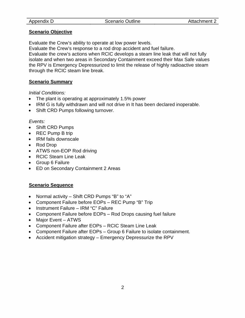
Appendix D Scenario Outline Attachment 2
2
Scenario Objective Evaluate the Crew’s ability to operate at low power levels. Evaluate the Crew’s response to a rod drop accident and fuel failure. Evaluate the crew’s actions when RCIC develops a steam line leak that will not fully isolate and when two areas in Secondary Containment exceed their Max Safe values the RPV is Emergency Depressurized to limit the release of highly radioactive steam through the RCIC steam line break. Scenario Summary Initial Conditions: • The plant is operating at approximately 1.5% power • IRM G is fully withdrawn and will not drive in It has been declared inoperable. • Shift CRD Pumps following turnover. Events: • Shift CRD Pumps • REC Pump B trip • IRM fails downscale • Rod Drop • ATWS non-EOP Rod driving • RCIC Steam Line Leak • Group 6 Failure • ED on Secondary Containment 2 Areas
Scenario Sequence • Normal activity – Shift CRD Pumps “B” to “A” • Component Failure before EOPs – REC Pump “B” Trip • Instrument Failure – IRM “C” Failure • Component Failure before EOPs – Rod Drops causing fuel failure • Major Event – ATWS • Component Failure after EOPs – RCIC Steam Line Leak • Component Failure after EOPs – Group 6 Failure to isolate containment. • Accident mitigation strategy – Emergency Depressurize the RPV
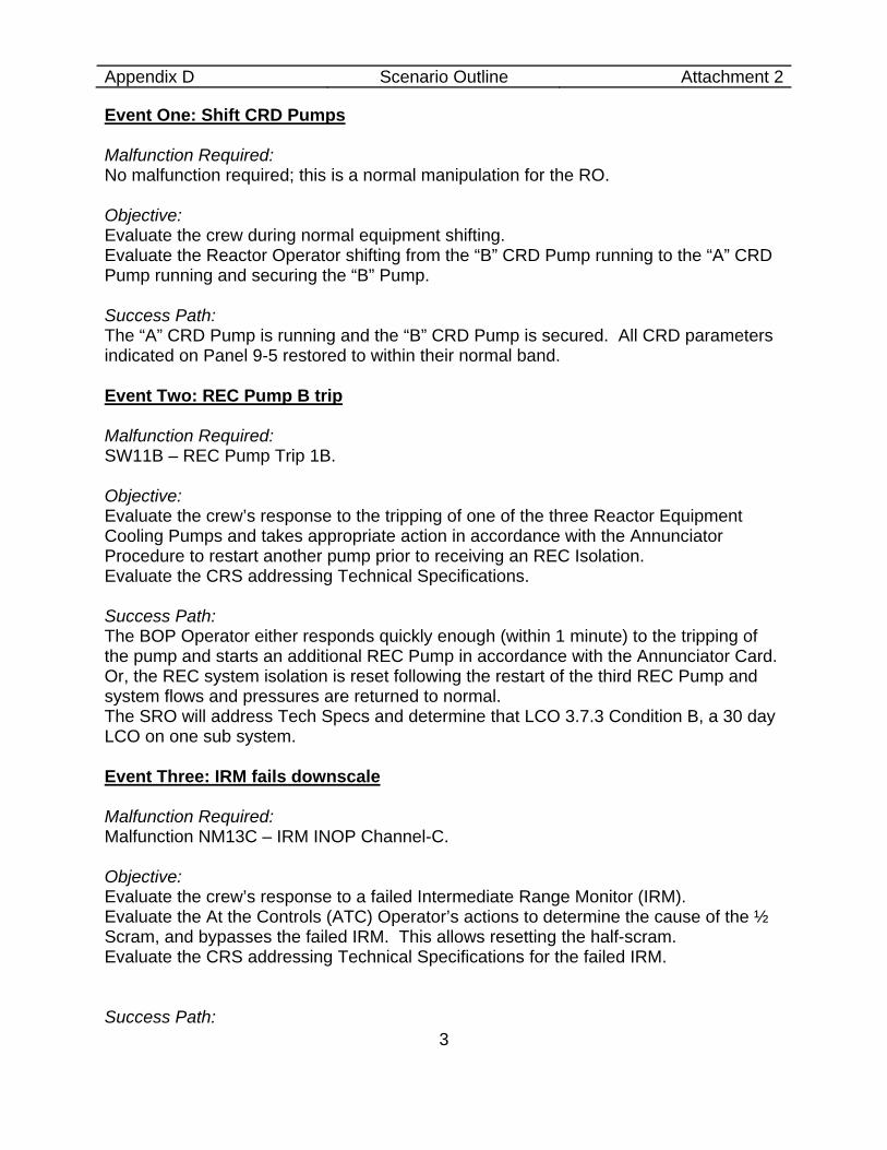
Appendix D Scenario Outline Attachment 2
3
Event One: Shift CRD Pumps Malfunction Required: No malfunction required; this is a normal manipulation for the RO. Objective: Evaluate the crew during normal equipment shifting. Evaluate the Reactor Operator shifting from the “B” CRD Pump running to the “A” CRD Pump running and securing the “B” Pump. Success Path: The “A” CRD Pump is running and the “B” CRD Pump is secured. All CRD parameters indicated on Panel 9-5 restored to within their normal band. Event Two: REC Pump B trip Malfunction Required: SW11B – REC Pump Trip 1B. Objective: Evaluate the crew’s response to the tripping of one of the three Reactor Equipment Cooling Pumps and takes appropriate action in accordance with the Annunciator Procedure to restart another pump prior to receiving an REC Isolation. Evaluate the CRS addressing Technical Specifications. Success Path: The BOP Operator either responds quickly enough (within 1 minute) to the tripping of the pump and starts an additional REC Pump in accordance with the Annunciator Card. Or, the REC system isolation is reset following the restart of the third REC Pump and system flows and pressures are returned to normal. The SRO will address Tech Specs and determine that LCO 3.7.3 Condition B, a 30 day LCO on one sub system. Event Three: IRM fails downscale Malfunction Required: Malfunction NM13C – IRM INOP Channel-C. Objective: Evaluate the crew’s response to a failed Intermediate Range Monitor (IRM). Evaluate the At the Controls (ATC) Operator’s actions to determine the cause of the ½ Scram, and bypasses the failed IRM. This allows resetting the half-scram. Evaluate the CRS addressing Technical Specifications for the failed IRM. Success Path:
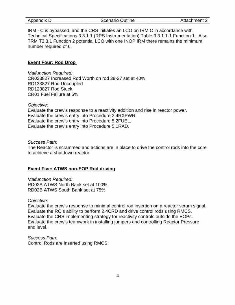
Appendix D Scenario Outline Attachment 2
4
IRM - C is bypassed, and the CRS initiates an LCO on IRM C in accordance with Technical Specifications 3.3.1.1 (RPS Instrumentation) Table 3.3.1.1-1 Function 1. Also TRM T3.3.1 Function 2 potential LCO with one INOP IRM there remains the minimum number required of 6. Event Four: Rod Drop Malfunction Required: CR023827 Increased Rod Worth on rod 38-27 set at 40% RD133827 Rod Uncoupled RD123827 Rod Stuck CR01 Fuel Failure at 5% Objective: Evaluate the crew’s response to a reactivity addition and rise in reactor power. Evaluate the crew’s entry into Procedure 2.4RXPWR. Evaluate the crew’s entry into Procedure 5.2FUEL. Evaluate the crew’s entry into Procedure 5.1RAD. Success Path: The Reactor is scrammed and actions are in place to drive the control rods into the core to achieve a shutdown reactor. Event Five: ATWS non-EOP Rod driving Malfunction Required: RD02A ATWS North Bank set at 100% RD02B ATWS South Bank set at 75% Objective: Evaluate the crew’s response to minimal control rod insertion on a reactor scram signal. Evaluate the RO’s ability to perform 2.4CRD and drive control rods using RMCS. Evaluate the CRS implementing strategy for reactivity controls outside the EOPs. Evaluate the crew’s teamwork in installing jumpers and controlling Reactor Pressure and level. Success Path: Control Rods are inserted using RMCS.
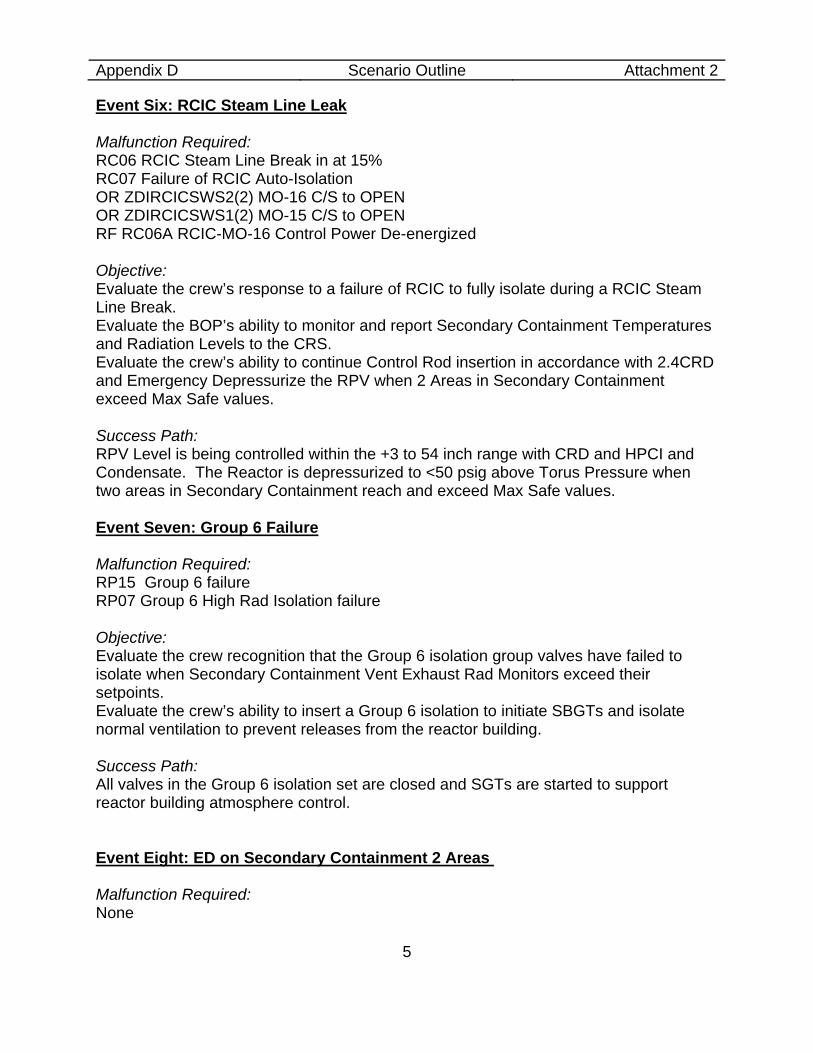
Appendix D Scenario Outline Attachment 2
5
Event Six: RCIC Steam Line Leak Malfunction Required: RC06 RCIC Steam Line Break in at 15% RC07 Failure of RCIC Auto-Isolation OR ZDIRCICSWS2(2) MO-16 C/S to OPEN OR ZDIRCICSWS1(2) MO-15 C/S to OPEN RF RC06A RCIC-MO-16 Control Power De-energized Objective: Evaluate the crew’s response to a failure of RCIC to fully isolate during a RCIC Steam Line Break. Evaluate the BOP’s ability to monitor and report Secondary Containment Temperatures and Radiation Levels to the CRS. Evaluate the crew’s ability to continue Control Rod insertion in accordance with 2.4CRD and Emergency Depressurize the RPV when 2 Areas in Secondary Containment exceed Max Safe values. Success Path: RPV Level is being controlled within the +3 to 54 inch range with CRD and HPCI and Condensate. The Reactor is depressurized to <50 psig above Torus Pressure when two areas in Secondary Containment reach and exceed Max Safe values. Event Seven: Group 6 Failure Malfunction Required: RP15 Group 6 failure RP07 Group 6 High Rad Isolation failure Objective: Evaluate the crew recognition that the Group 6 isolation group valves have failed to isolate when Secondary Containment Vent Exhaust Rad Monitors exceed their setpoints. Evaluate the crew’s ability to insert a Group 6 isolation to initiate SBGTs and isolate normal ventilation to prevent releases from the reactor building. Success Path: All valves in the Group 6 isolation set are closed and SGTs are started to support reactor building atmosphere control. Event Eight: ED on Secondary Containment 2 Areas Malfunction Required: None
Appendix D Scenario Outline Attachment 2
6
Objective: Evaluate the crew response to a slow increase in Reactor Building Temperatures and Radiation levels to the point where the RPV must be Emergency Depressurized. Evaluate the crew’s ability to manually open 6 SRVs and reduce RPV Pressure to less than 50 psig above Torus pressure, in accordance with the EOPs. Success Path: RPV is depressurized to 50 psig above Torus pressure. Scenario Termination: When Reactor water level is being controlled between +3 and +54 inches and the RPV has been Emergency Depressurized and all but one Control Rod have been inserted.
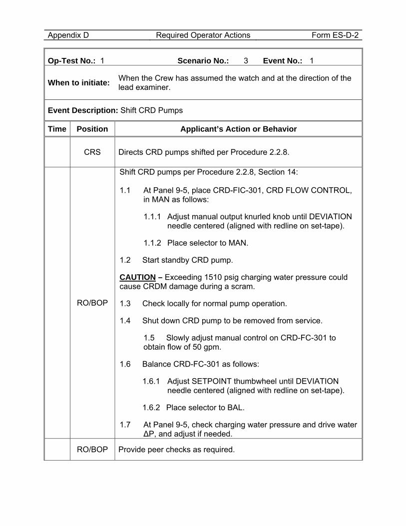
Appendix D Required Operator Actions Form ES-D-2
Op-Test No.: 1 Scenario No.: 3 Event No.: 1
When to initiate: When the Crew has assumed the watch and at the direction of the lead examiner.
Event Description: Shift CRD Pumps
Time Position Applicant’s Action or Behavior
CRS Directs CRD pumps shifted per Procedure 2.2.8.
RO/BOP
Shift CRD pumps per Procedure 2.2.8, Section 14: 1.1 At Panel 9-5, place CRD-FIC-301, CRD FLOW CONTROL,
in MAN as follows:
1.1.1 Adjust manual output knurled knob until DEVIATION needle centered (aligned with redline on set-tape).
1.1.2 Place selector to MAN.
1.2 Start standby CRD pump.
CAUTION – Exceeding 1510 psig charging water pressure could cause CRDM damage during a scram.
1.3 Check locally for normal pump operation.
1.4 Shut down CRD pump to be removed from service.
1.5 Slowly adjust manual control on CRD-FC-301 to obtain flow of 50 gpm.
1.6 Balance CRD-FC-301 as follows:
1.6.1 Adjust SETPOINT thumbwheel until DEVIATION needle centered (aligned with redline on set-tape).
1.6.2 Place selector to BAL.
1.7 At Panel 9-5, check charging water pressure and drive water ∆P, and adjust if needed.
RO/BOP Provide peer checks as required.

Appendix D Required Operator Actions Form ES-D-2
Op-Test No.: 1 Scenario No.: 3 Event No.: 1
When to initiate: When the Crew has assumed the watch and at the direction of the lead examiner.
Event Description: Shift CRD Pumps
Time Position Applicant’s Action or Behavior
END OF EVENT
Notes
Proceed to the next event at direction of the lead examiner.
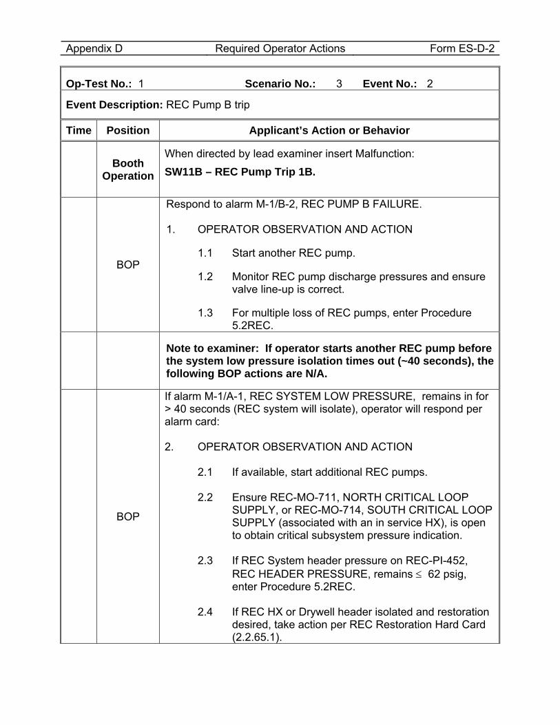
Appendix D Required Operator Actions Form ES-D-2
Op-Test No.: 1 Scenario No.: 3 Event No.: 2
Event Description: REC Pump B trip
Time Position Applicant’s Action or Behavior
Booth Operation
When directed by lead examiner insert Malfunction: SW11B – REC Pump Trip 1B.
BOP
Respond to alarm M-1/B-2, REC PUMP B FAILURE. 1. OPERATOR OBSERVATION AND ACTION
1.1 Start another REC pump.
1.2 Monitor REC pump discharge pressures and ensure valve line-up is correct.
1.3 For multiple loss of REC pumps, enter Procedure 5.2REC.
Note to examiner: If operator starts another REC pump before the system low pressure isolation times out (~40 seconds), the following BOP actions are N/A.
BOP
If alarm M-1/A-1, REC SYSTEM LOW PRESSURE, remains in for > 40 seconds (REC system will isolate), operator will respond per alarm card: 2. OPERATOR OBSERVATION AND ACTION
2.1 If available, start additional REC pumps. 2.2 Ensure REC-MO-711, NORTH CRITICAL LOOP
SUPPLY, or REC-MO-714, SOUTH CRITICAL LOOP SUPPLY (associated with an in service HX), is open to obtain critical subsystem pressure indication.
2.3 If REC System header pressure on REC-PI-452,
REC HEADER PRESSURE, remains ≤ 62 psig, enter Procedure 5.2REC.
2.4 If REC HX or Drywell header isolated and restoration
desired, take action per REC Restoration Hard Card (2.2.65.1).
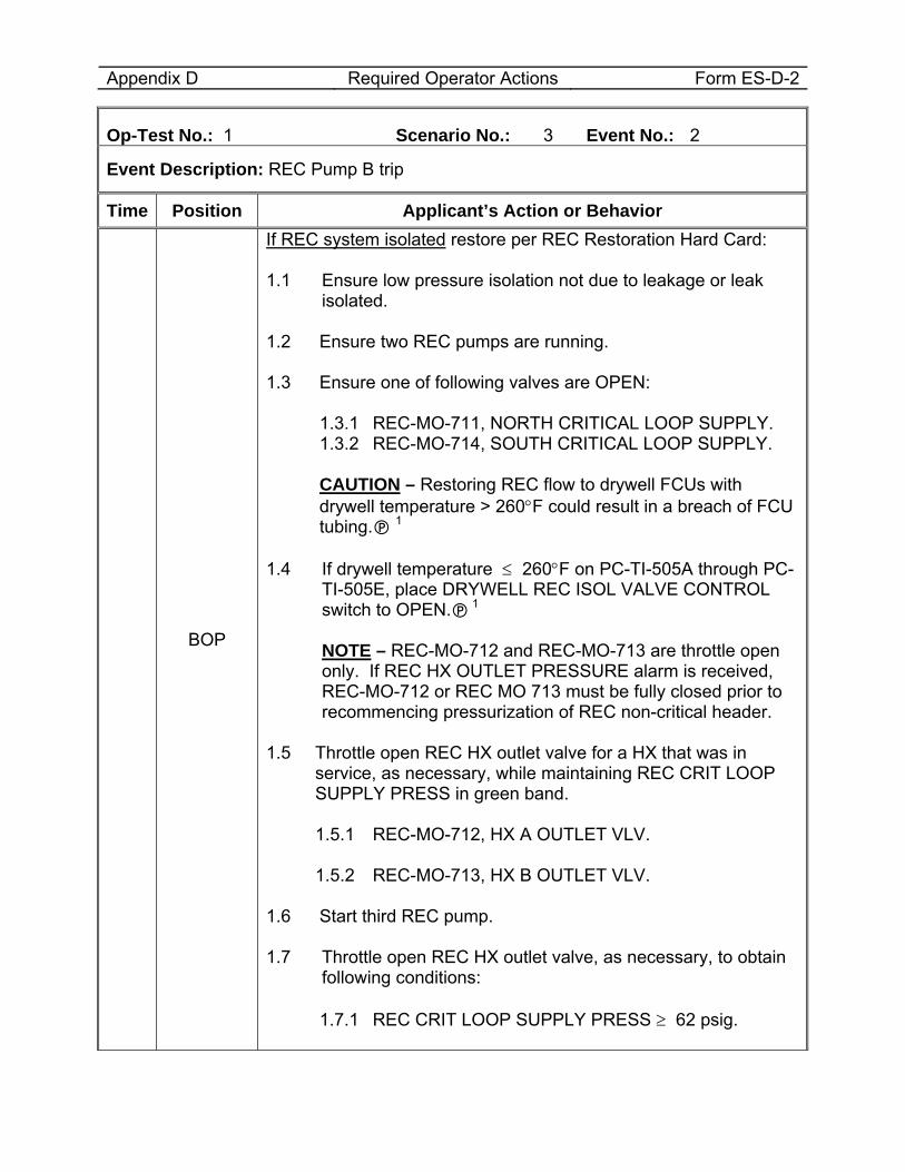
Appendix D Required Operator Actions Form ES-D-2
Op-Test No.: 1 Scenario No.: 3 Event No.: 2
Event Description: REC Pump B trip
Time Position Applicant’s Action or Behavior
BOP
If REC system isolated restore per REC Restoration Hard Card: 1.1 Ensure low pressure isolation not due to leakage or leak
isolated. 1.2 Ensure two REC pumps are running. 1.3 Ensure one of following valves are OPEN:
1.3.1 REC-MO-711, NORTH CRITICAL LOOP SUPPLY. 1.3.2 REC-MO-714, SOUTH CRITICAL LOOP SUPPLY. CAUTION – Restoring REC flow to drywell FCUs with drywell temperature > 260°F could result in a breach of FCU tubing. 1
1.4 If drywell temperature ≤ 260°F on PC-TI-505A through PC-
TI-505E, place DRYWELL REC ISOL VALVE CONTROL switch to OPEN. 1
NOTE – REC-MO-712 and REC-MO-713 are throttle open only. If REC HX OUTLET PRESSURE alarm is received, REC-MO-712 or REC MO 713 must be fully closed prior to recommencing pressurization of REC non-critical header.
1.5 Throttle open REC HX outlet valve for a HX that was in service, as necessary, while maintaining REC CRIT LOOP SUPPLY PRESS in green band.
1.5.1 REC-MO-712, HX A OUTLET VLV. 1.5.2 REC-MO-713, HX B OUTLET VLV.
1.6 Start third REC pump. 1.7 Throttle open REC HX outlet valve, as necessary, to obtain
following conditions:
1.7.1 REC CRIT LOOP SUPPLY PRESS ≥ 62 psig.
Appendix D Required Operator Actions Form ES-D-2
Op-Test No.: 1 Scenario No.: 3 Event No.: 2
Event Description: REC Pump B trip
Time Position Applicant’s Action or Behavior 1.7.2 REC HEADER PRESSURE in top of green band.
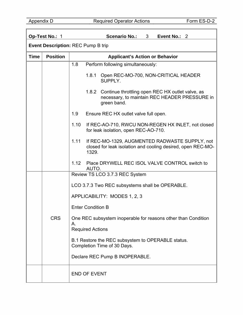
Appendix D Required Operator Actions Form ES-D-2
Op-Test No.: 1 Scenario No.: 3 Event No.: 2
Event Description: REC Pump B trip
Time Position Applicant’s Action or Behavior
1.8 Perform following simultaneously:
1.8.1 Open REC-MO-700, NON-CRITICAL HEADER SUPPLY.
1.8.2 Continue throttling open REC HX outlet valve, as
necessary, to maintain REC HEADER PRESSURE in green band.
1.9 Ensure REC HX outlet valve full open. 1.10 If REC-AO-710, RWCU NON-REGEN HX INLET, not closed
for leak isolation, open REC-AO-710. 1.11 If REC-MO-1329, AUGMENTED RADWASTE SUPPLY, not
closed for leak isolation and cooling desired, open REC-MO-1329.
1.12 Place DRYWELL REC ISOL VALVE CONTROL switch to
AUTO.
CRS
Review TS LCO 3.7.3 REC System LCO 3.7.3 Two REC subsystems shall be OPERABLE. APPLICABILITY: MODES 1, 2, 3 Enter Condition B One REC subsystem inoperable for reasons other than Condition A. Required Actions B.1 Restore the REC subsystem to OPERABLE status. Completion Time of 30 Days. Declare REC Pump B INOPERABLE.
END OF EVENT
Appendix D Required Operator Actions Form ES-D-2
Op-Test No.: 1 Scenario No.: 3 Event No.: 2
Event Description: REC Pump B trip
Time Position Applicant’s Action or Behavior
Notes
Proceed to the next event at direction of the lead examiner.
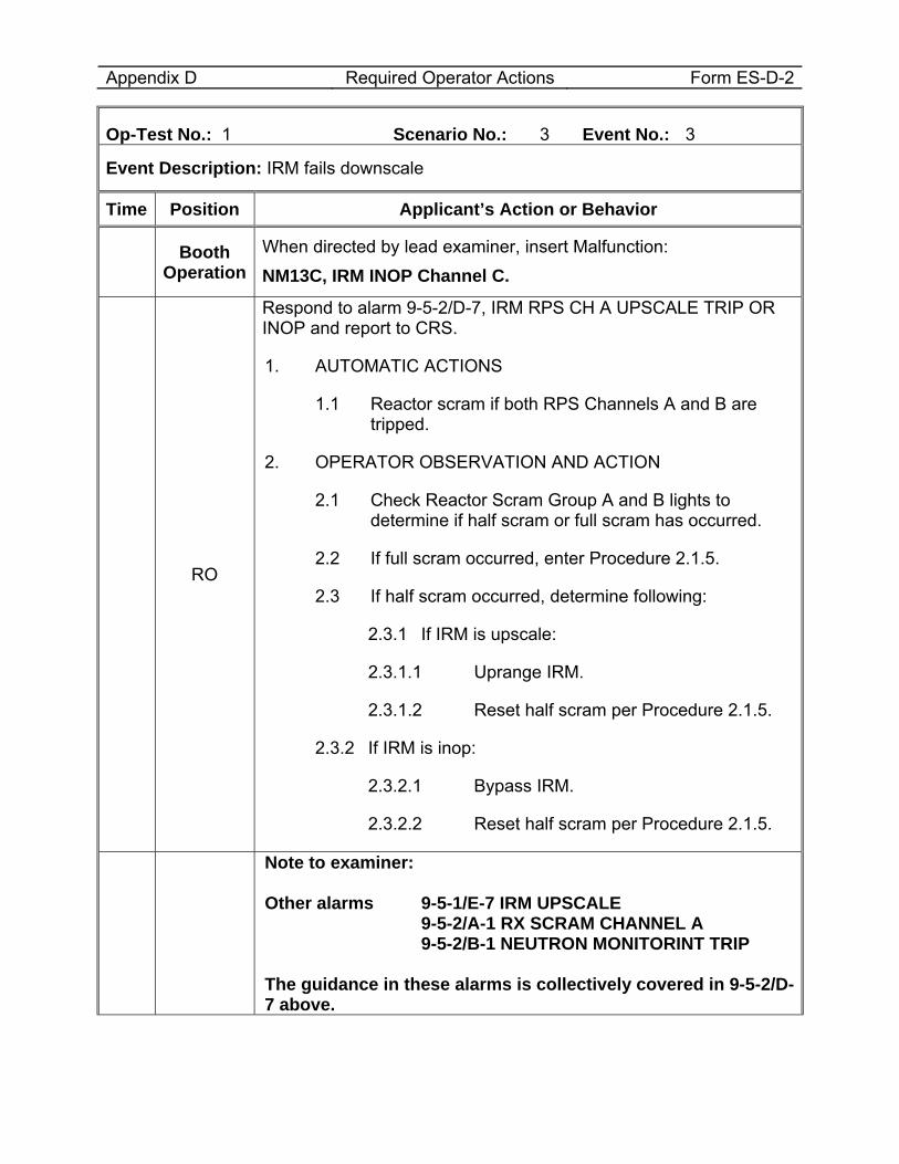
Appendix D Required Operator Actions Form ES-D-2
Op-Test No.: 1 Scenario No.: 3 Event No.: 3
Event Description: IRM fails downscale
Time Position Applicant’s Action or Behavior
Booth Operation
When directed by lead examiner, insert Malfunction: NM13C, IRM INOP Channel C.
RO
Respond to alarm 9-5-2/D-7, IRM RPS CH A UPSCALE TRIP OR INOP and report to CRS.
1. AUTOMATIC ACTIONS
1.1 Reactor scram if both RPS Channels A and B are tripped.
2. OPERATOR OBSERVATION AND ACTION
2.1 Check Reactor Scram Group A and B lights to determine if half scram or full scram has occurred.
2.2 If full scram occurred, enter Procedure 2.1.5.
2.3 If half scram occurred, determine following:
2.3.1 If IRM is upscale:
2.3.1.1 Uprange IRM.
2.3.1.2 Reset half scram per Procedure 2.1.5.
2.3.2 If IRM is inop:
2.3.2.1 Bypass IRM.
2.3.2.2 Reset half scram per Procedure 2.1.5.
Note to examiner: Other alarms 9-5-1/E-7 IRM UPSCALE 9-5-2/A-1 RX SCRAM CHANNEL A 9-5-2/B-1 NEUTRON MONITORINT TRIP The guidance in these alarms is collectively covered in 9-5-2/D-7 above.
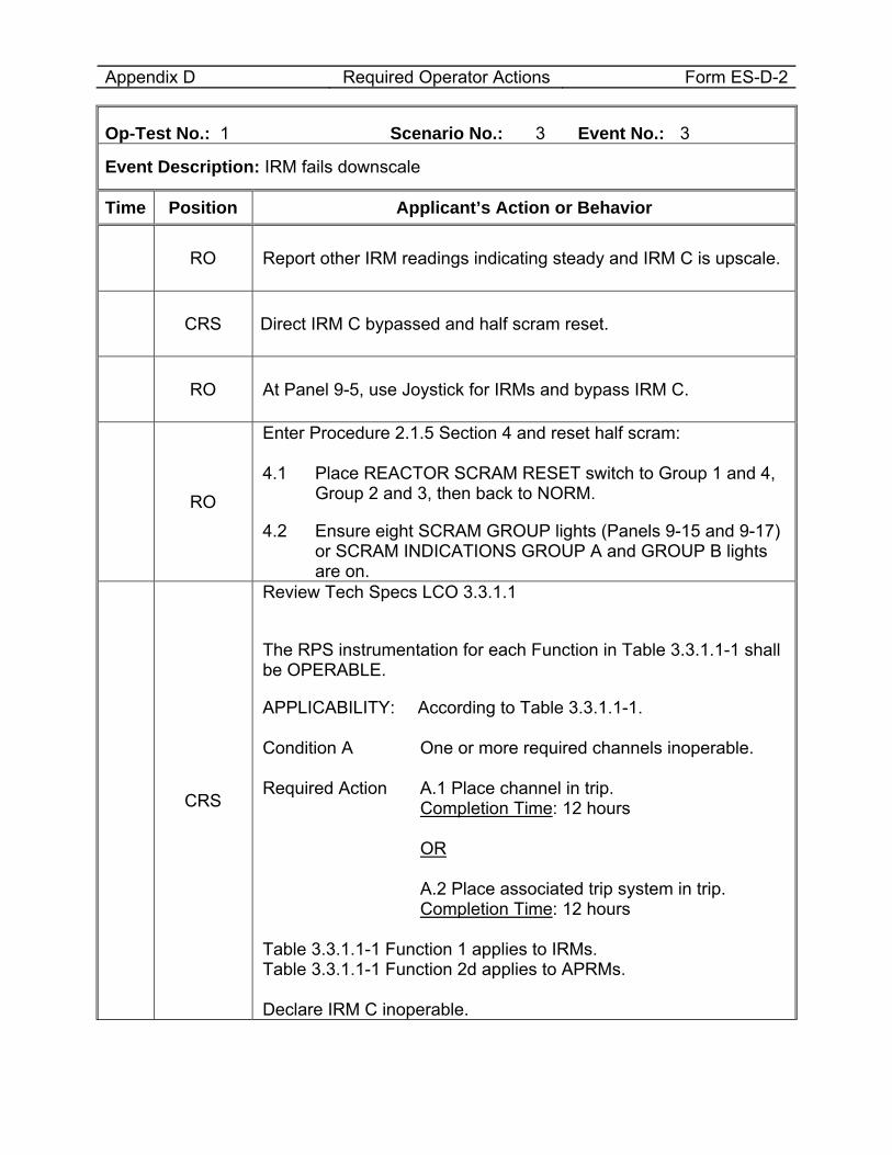
Appendix D Required Operator Actions Form ES-D-2
Op-Test No.: 1 Scenario No.: 3 Event No.: 3
Event Description: IRM fails downscale
Time Position Applicant’s Action or Behavior
RO Report other IRM readings indicating steady and IRM C is upscale.
CRS Direct IRM C bypassed and half scram reset.
RO At Panel 9-5, use Joystick for IRMs and bypass IRM C.
RO
Enter Procedure 2.1.5 Section 4 and reset half scram: 4.1 Place REACTOR SCRAM RESET switch to Group 1 and 4,
Group 2 and 3, then back to NORM.
4.2 Ensure eight SCRAM GROUP lights (Panels 9-15 and 9-17) or SCRAM INDICATIONS GROUP A and GROUP B lights are on.
CRS
Review Tech Specs LCO 3.3.1.1
The RPS instrumentation for each Function in Table 3.3.1.1-1 shall be OPERABLE.
APPLICABILITY: According to Table 3.3.1.1-1. Condition A One or more required channels inoperable. Required Action A.1 Place channel in trip. Completion Time: 12 hours OR A.2 Place associated trip system in trip. Completion Time: 12 hours Table 3.3.1.1-1 Function 1 applies to IRMs. Table 3.3.1.1-1 Function 2d applies to APRMs. Declare IRM C inoperable.
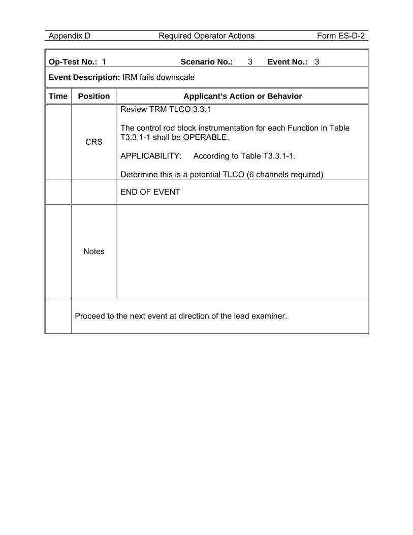
Appendix D Required Operator Actions Form ES-D-2
Op-Test No.: 1 Scenario No.: 3 Event No.: 3
Event Description: IRM fails downscale
Time Position Applicant’s Action or Behavior
CRS
Review TRM TLCO 3.3.1 The control rod block instrumentation for each Function in Table T3.3.1-1 shall be OPERABLE. APPLICABILITY: According to Table T3.3.1-1. Determine this is a potential TLCO (6 channels required)
END OF EVENT
Notes
Proceed to the next event at direction of the lead examiner.
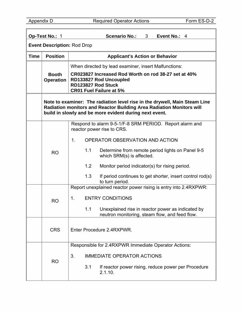
Appendix D Required Operator Actions Form ES-D-2
Op-Test No.: 1 Scenario No.: 3 Event No.: 4
Event Description: Rod Drop
Time Position Applicant’s Action or Behavior
Booth Operation
When directed by lead examiner, insert Malfunctions: CR023827 Increased Rod Worth on rod 38-27 set at 40% RD133827 Rod Uncoupled RD123827 Rod Stuck CR01 Fuel Failure at 5%
Note to examiner: The radiation level rise in the drywell, Main Steam Line Radiation monitors and Reactor Building Area Radiation Monitors will build in slowly and be more evident during next event.
RO
Respond to alarm 9-5-1/F-8 SRM PERIOD. Report alarm and reactor power rise to CRS. 1. OPERATOR OBSERVATION AND ACTION
1.1 Determine from remote period lights on Panel 9-5 which SRM(s) is affected.
1.2 Monitor period indicator(s) for rising period.
1.3 If period continues to get shorter, insert control rod(s) to turn period.
RO
Report unexplained reactor power rising is entry into 2.4RXPWR: 1. ENTRY CONDITIONS
1.1 Unexplained rise in reactor power as indicated by neutron monitoring, steam flow, and feed flow.
CRS Enter Procedure 2.4RXPWR.
RO
Responsible for 2.4RXPWR Immediate Operator Actions: 3. IMMEDIATE OPERATOR ACTIONS
3.1 If reactor power rising, reduce power per Procedure 2.1.10.
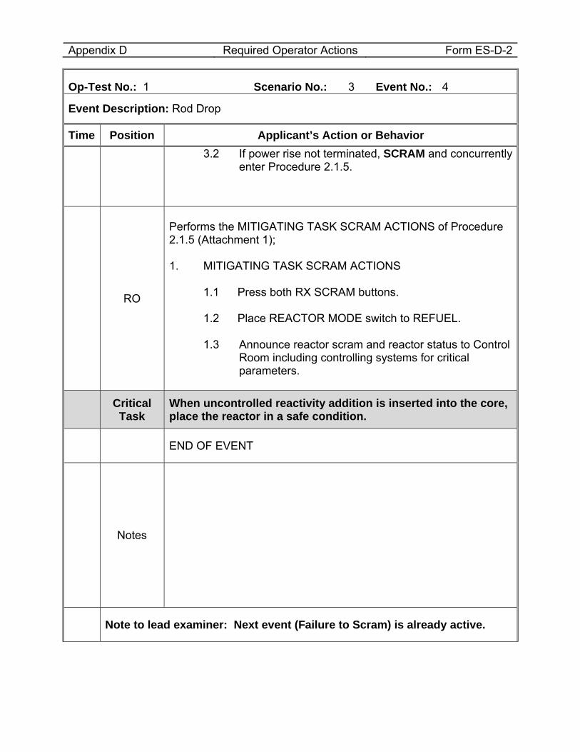
Appendix D Required Operator Actions Form ES-D-2
Op-Test No.: 1 Scenario No.: 3 Event No.: 4
Event Description: Rod Drop
Time Position Applicant’s Action or Behavior 3.2 If power rise not terminated, SCRAM and concurrently
enter Procedure 2.1.5.
RO
Performs the MITIGATING TASK SCRAM ACTIONS of Procedure 2.1.5 (Attachment 1); 1. MITIGATING TASK SCRAM ACTIONS
1.1 Press both RX SCRAM buttons. 1.2 Place REACTOR MODE switch to REFUEL. 1.3 Announce reactor scram and reactor status to Control
Room including controlling systems for critical parameters.
Critical Task
When uncontrolled reactivity addition is inserted into the core, place the reactor in a safe condition.
END OF EVENT
Notes
Note to lead examiner: Next event (Failure to Scram) is already active.
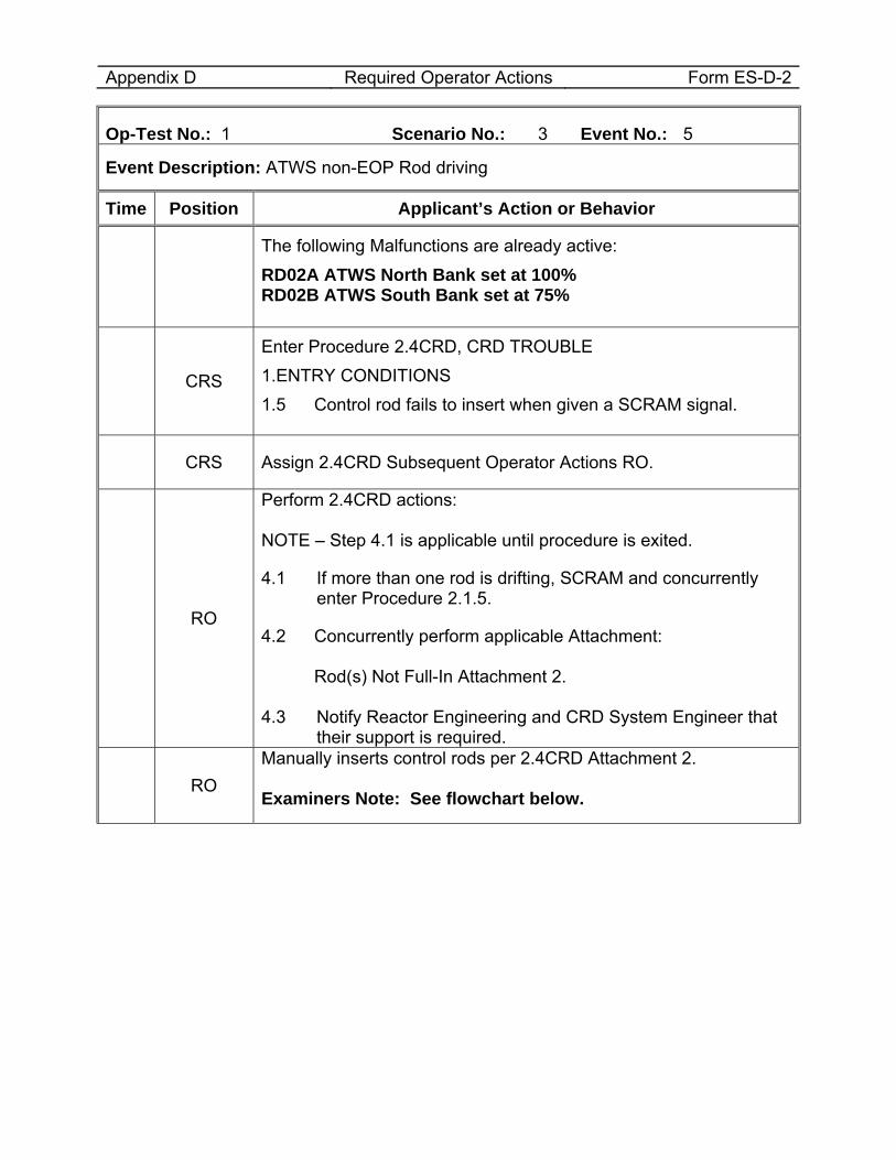
Appendix D Required Operator Actions Form ES-D-2
Op-Test No.: 1 Scenario No.: 3 Event No.: 5
Event Description: ATWS non-EOP Rod driving
Time Position Applicant’s Action or Behavior
The following Malfunctions are already active: RD02A ATWS North Bank set at 100% RD02B ATWS South Bank set at 75%
CRS
Enter Procedure 2.4CRD, CRD TROUBLE 1.ENTRY CONDITIONS 1.5 Control rod fails to insert when given a SCRAM signal.
CRS Assign 2.4CRD Subsequent Operator Actions RO.
RO
Perform 2.4CRD actions: NOTE – Step 4.1 is applicable until procedure is exited.
4.1 If more than one rod is drifting, SCRAM and concurrently enter Procedure 2.1.5.
4.2 Concurrently perform applicable Attachment: Rod(s) Not Full-In Attachment 2. 4.3 Notify Reactor Engineering and CRD System Engineer that
their support is required.
RO Manually inserts control rods per 2.4CRD Attachment 2. Examiners Note: See flowchart below.
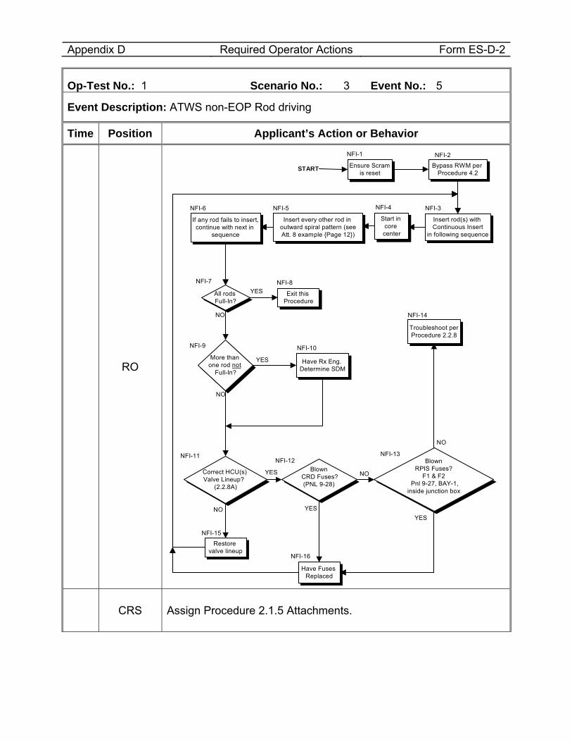
Appendix D Required Operator Actions Form ES-D-2
Op-Test No.: 1 Scenario No.: 3 Event No.: 5
Event Description: ATWS non-EOP Rod driving
Time Position Applicant’s Action or Behavior
RO YES
If any rod fails to insert, continue with next in
sequence
More than one rod not
Full-In?
Have Rx Eng. Determine SDM
Correct HCU(s) Valve Lineup?
(2.2.8A)
Restore valve lineup
Blown CRD Fuses?
(PNL 9-28)
Have Fuses Replaced
Blown RPIS Fuses?
F1 & F2 Pnl 9-27, BAY-1,
inside junction box
Troubleshoot per Procedure 2.2.8
NO YES
NO
YES
NO
YES
All rods Full-In?
Exit this Procedure
NO
NO
START Bypass RWM per Procedure 4.2
Insert rod(s) with Continuous Insert
in following sequence
Start in core center
Insert every other rod in outward spiral pattern (see Att. 8 example {Page 12})
YES
Ensure Scram is reset
NFI-1 NFI-2
NFI-6 NFI-5 NFI-4 NFI-3
NFI-8NFI-7
NFI-9 NFI-10
NFI-14
NFI-11NFI-12
NFI-13
NFI-15
NFI-16
CRS Assign Procedure 2.1.5 Attachments.
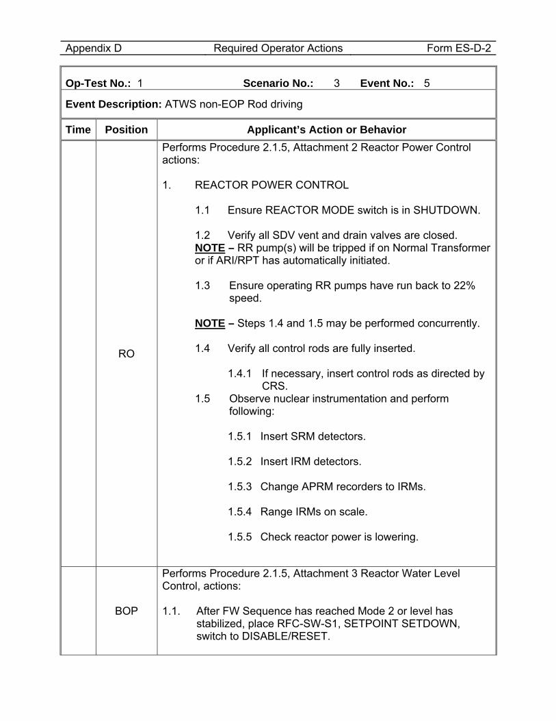
Appendix D Required Operator Actions Form ES-D-2
Op-Test No.: 1 Scenario No.: 3 Event No.: 5
Event Description: ATWS non-EOP Rod driving
Time Position Applicant’s Action or Behavior
RO
Performs Procedure 2.1.5, Attachment 2 Reactor Power Control actions: 1. REACTOR POWER CONTROL
1.1 Ensure REACTOR MODE switch is in SHUTDOWN. 1.2 Verify all SDV vent and drain valves are closed. NOTE – RR pump(s) will be tripped if on Normal Transformer or if ARI/RPT has automatically initiated.
1.3 Ensure operating RR pumps have run back to 22%
speed. NOTE – Steps 1.4 and 1.5 may be performed concurrently.
1.4 Verify all control rods are fully inserted.
1.4.1 If necessary, insert control rods as directed by CRS.
1.5 Observe nuclear instrumentation and perform following:
1.5.1 Insert SRM detectors. 1.5.2 Insert IRM detectors. 1.5.3 Change APRM recorders to IRMs. 1.5.4 Range IRMs on scale. 1.5.5 Check reactor power is lowering.
BOP
Performs Procedure 2.1.5, Attachment 3 Reactor Water Level Control, actions: 1.1. After FW Sequence has reached Mode 2 or level has
stabilized, place RFC-SW-S1, SETPOINT SETDOWN, switch to DISABLE/RESET.
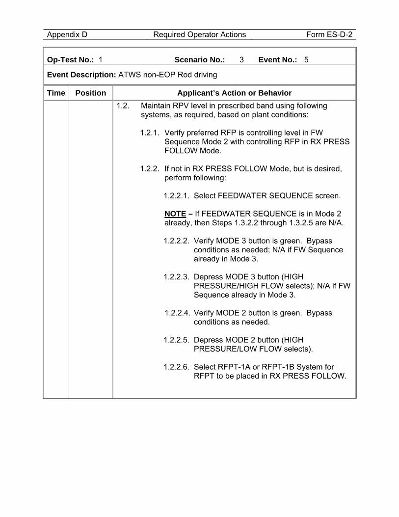
Appendix D Required Operator Actions Form ES-D-2
Op-Test No.: 1 Scenario No.: 3 Event No.: 5
Event Description: ATWS non-EOP Rod driving
Time Position Applicant’s Action or Behavior 1.2. Maintain RPV level in prescribed band using following
systems, as required, based on plant conditions:
1.2.1. Verify preferred RFP is controlling level in FW Sequence Mode 2 with controlling RFP in RX PRESS FOLLOW Mode.
1.2.2. If not in RX PRESS FOLLOW Mode, but is desired,
perform following:
1.2.2.1. Select FEEDWATER SEQUENCE screen.
NOTE – If FEEDWATER SEQUENCE is in Mode 2 already, then Steps 1.3.2.2 through 1.3.2.5 are N/A.
1.2.2.2. Verify MODE 3 button is green. Bypass
conditions as needed; N/A if FW Sequence already in Mode 3.
1.2.2.3. Depress MODE 3 button (HIGH
PRESSURE/HIGH FLOW selects); N/A if FW Sequence already in Mode 3.
1.2.2.4. Verify MODE 2 button is green. Bypass
conditions as needed. 1.2.2.5. Depress MODE 2 button (HIGH
PRESSURE/LOW FLOW selects).
1.2.2.6. Select RFPT-1A or RFPT-1B System for RFPT to be placed in RX PRESS FOLLOW.
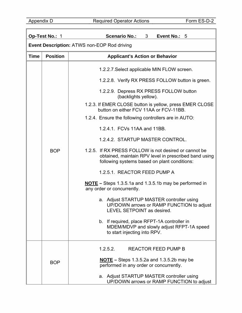
Appendix D Required Operator Actions Form ES-D-2
Op-Test No.: 1 Scenario No.: 3 Event No.: 5
Event Description: ATWS non-EOP Rod driving
Time Position Applicant’s Action or Behavior
BOP
1.2.2.7.Select applicable MIN FLOW screen. 1.2.2.8. Verify RX PRESS FOLLOW button is green. 1.2.2.9. Depress RX PRESS FOLLOW button
(backlights yellow). 1.2.3. If EMER CLOSE button is yellow, press EMER CLOSE
button on either FCV 11AA or FCV-11BB. 1.2.4. Ensure the following controllers are in AUTO:
1.2.4.1. FCVs 11AA and 11BB.
1.2.4.2. STARTUP MASTER CONTROL.
1.2.5. If RX PRESS FOLLOW is not desired or cannot be
obtained, maintain RPV level in prescribed band using following systems based on plant conditions:
1.2.5.1. REACTOR FEED PUMP A
NOTE – Steps 1.3.5.1a and 1.3.5.1b may be performed in any order or concurrently.
a. Adjust STARTUP MASTER controller using
UP/DOWN arrows or RAMP FUNCTION to adjust LEVEL SETPOINT as desired.
b. If required, place RFPT-1A controller in
MDEM/MDVP and slowly adjust RFPT-1A speed to start injecting into RPV.
BOP
1.2.5.2. REACTOR FEED PUMP B
NOTE – Steps 1.3.5.2a and 1.3.5.2b may be
performed in any order or concurrently.
a. Adjust STARTUP MASTER controller using UP/DOWN arrows or RAMP FUNCTION to adjust
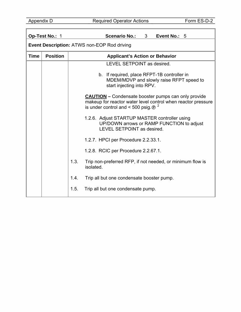
Appendix D Required Operator Actions Form ES-D-2
Op-Test No.: 1 Scenario No.: 3 Event No.: 5
Event Description: ATWS non-EOP Rod driving
Time Position Applicant’s Action or Behavior LEVEL SETPOINT as desired.
b. If required, place RFPT-1B controller in
MDEM/MDVP and slowly raise RFPT speed to start injecting into RPV.
CAUTION – Condensate booster pumps can only provide
makeup for reactor water level control when reactor pressure is under control and < 500 psig. 2
1.2.6. Adjust STARTUP MASTER controller using
UP/DOWN arrows or RAMP FUNCTION to adjust LEVEL SETPOINT as desired.
1.2.7. HPCI per Procedure 2.2.33.1.
1.2.8. RCIC per Procedure 2.2.67.1.
1.3. Trip non-preferred RFP, if not needed, or minimum flow is
isolated. 1.4. Trip all but one condensate booster pump. 1.5. Trip all but one condensate pump.
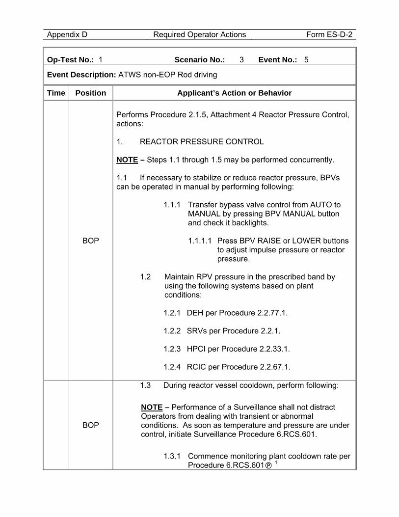
Appendix D Required Operator Actions Form ES-D-2
Op-Test No.: 1 Scenario No.: 3 Event No.: 5
Event Description: ATWS non-EOP Rod driving
Time Position Applicant’s Action or Behavior
BOP
Performs Procedure 2.1.5, Attachment 4 Reactor Pressure Control, actions: 1. REACTOR PRESSURE CONTROL NOTE – Steps 1.1 through 1.5 may be performed concurrently. 1.1 If necessary to stabilize or reduce reactor pressure, BPVs can be operated in manual by performing following:
1.1.1 Transfer bypass valve control from AUTO to MANUAL by pressing BPV MANUAL button and check it backlights.
1.1.1.1 Press BPV RAISE or LOWER buttons
to adjust impulse pressure or reactor pressure.
1.2 Maintain RPV pressure in the prescribed band by
using the following systems based on plant conditions:
1.2.1 DEH per Procedure 2.2.77.1.
1.2.2 SRVs per Procedure 2.2.1.
1.2.3 HPCI per Procedure 2.2.33.1.
1.2.4 RCIC per Procedure 2.2.67.1.
BOP
1.3 During reactor vessel cooldown, perform following:
NOTE – Performance of a Surveillance shall not distract Operators from dealing with transient or abnormal conditions. As soon as temperature and pressure are under control, initiate Surveillance Procedure 6.RCS.601.
1.3.1 Commence monitoring plant cooldown rate per
Procedure 6.RCS.601 1
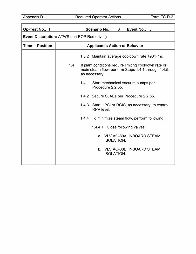
Appendix D Required Operator Actions Form ES-D-2
Op-Test No.: 1 Scenario No.: 3 Event No.: 5
Event Description: ATWS non-EOP Rod driving
Time Position Applicant’s Action or Behavior
1.3.2 Maintain average cooldown rate ≤90°F/hr.
1.4 If plant conditions require limiting cooldown rate or main steam flow, perform Steps 1.4.1 through 1.4.5, as necessary.
1.4.1 Start mechanical vacuum pumps per
Procedure 2.2.55.
1.4.2 Secure SJAEs per Procedure 2.2.55.
1.4.3 Start HPCI or RCIC, as necessary, to control RPV level.
1.4.4 To minimize steam flow, perform following:
1.4.4.1 Close following valves:
a. VLV AO-80A, INBOARD STEAM
ISOLATION.
b. VLV AO-80B, INBOARD STEAM ISOLATION.
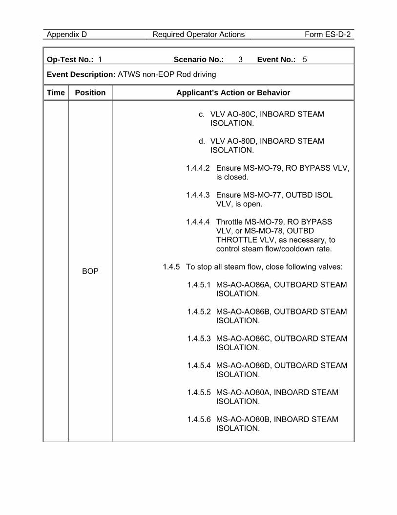
Appendix D Required Operator Actions Form ES-D-2
Op-Test No.: 1 Scenario No.: 3 Event No.: 5
Event Description: ATWS non-EOP Rod driving
Time Position Applicant’s Action or Behavior
BOP
c. VLV AO-80C, INBOARD STEAM
ISOLATION.
d. VLV AO-80D, INBOARD STEAM ISOLATION.
1.4.4.2 Ensure MS-MO-79, RO BYPASS VLV,
is closed.
1.4.4.3 Ensure MS-MO-77, OUTBD ISOL VLV, is open.
1.4.4.4 Throttle MS-MO-79, RO BYPASS
VLV, or MS-MO-78, OUTBD THROTTLE VLV, as necessary, to control steam flow/cooldown rate.
1.4.5 To stop all steam flow, close following valves:
1.4.5.1 MS-AO-AO86A, OUTBOARD STEAM
ISOLATION. 1.4.5.2 MS-AO-AO86B, OUTBOARD STEAM
ISOLATION. 1.4.5.3 MS-AO-AO86C, OUTBOARD STEAM
ISOLATION. 1.4.5.4 MS-AO-AO86D, OUTBOARD STEAM
ISOLATION. 1.4.5.5 MS-AO-AO80A, INBOARD STEAM
ISOLATION. 1.4.5.6 MS-AO-AO80B, INBOARD STEAM
ISOLATION.
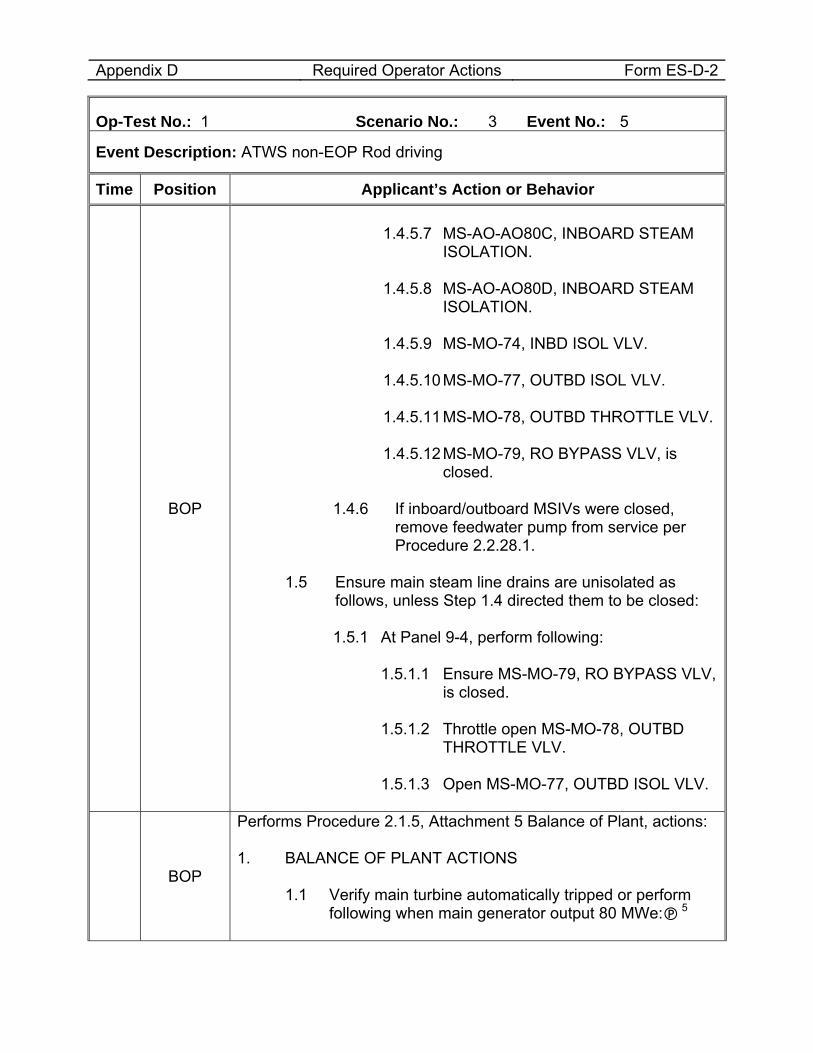
Appendix D Required Operator Actions Form ES-D-2
Op-Test No.: 1 Scenario No.: 3 Event No.: 5
Event Description: ATWS non-EOP Rod driving
Time Position Applicant’s Action or Behavior
BOP
1.4.5.7 MS-AO-AO80C, INBOARD STEAM
ISOLATION. 1.4.5.8 MS-AO-AO80D, INBOARD STEAM
ISOLATION. 1.4.5.9 MS-MO-74, INBD ISOL VLV. 1.4.5.10 MS-MO-77, OUTBD ISOL VLV. 1.4.5.11 MS-MO-78, OUTBD THROTTLE VLV. 1.4.5.12 MS-MO-79, RO BYPASS VLV, is
closed.
1.4.6 If inboard/outboard MSIVs were closed, remove feedwater pump from service per Procedure 2.2.28.1.
1.5 Ensure main steam line drains are unisolated as
follows, unless Step 1.4 directed them to be closed:
1.5.1 At Panel 9-4, perform following:
1.5.1.1 Ensure MS-MO-79, RO BYPASS VLV, is closed.
1.5.1.2 Throttle open MS-MO-78, OUTBD
THROTTLE VLV. 1.5.1.3 Open MS-MO-77, OUTBD ISOL VLV.
BOP
Performs Procedure 2.1.5, Attachment 5 Balance of Plant, actions: 1. BALANCE OF PLANT ACTIONS
1.1 Verify main turbine automatically tripped or perform following when main generator output 80 MWe: 5
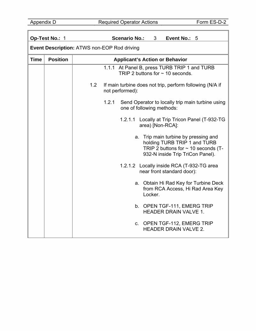
Appendix D Required Operator Actions Form ES-D-2
Op-Test No.: 1 Scenario No.: 3 Event No.: 5
Event Description: ATWS non-EOP Rod driving
Time Position Applicant’s Action or Behavior 1.1.1 At Panel B, press TURB TRIP 1 and TURB
TRIP 2 buttons for ~ 10 seconds.
1.2 If main turbine does not trip, perform following (N/A if not performed):
1.2.1 Send Operator to locally trip main turbine using
one of following methods:
1.2.1.1 Locally at Trip Tricon Panel (T-932-TG area) [Non-RCA]:
a. Trip main turbine by pressing and
holding TURB TRIP 1 and TURB TRIP 2 buttons for ~ 10 seconds (T-932-N inside Trip TriCon Panel).
1.2.1.2 Locally inside RCA (T-932-TG area
near front standard door):
a. Obtain Hi Rad Key for Turbine Deck from RCA Access, Hi Rad Area Key Locker.
b. OPEN TGF-111, EMERG TRIP
HEADER DRAIN VALVE 1. c. OPEN TGF-112, EMERG TRIP
HEADER DRAIN VALVE 2.
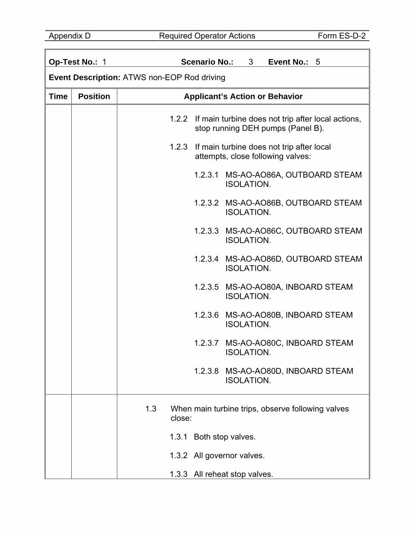
Appendix D Required Operator Actions Form ES-D-2
Op-Test No.: 1 Scenario No.: 3 Event No.: 5
Event Description: ATWS non-EOP Rod driving
Time Position Applicant’s Action or Behavior
1.2.2 If main turbine does not trip after local actions,
stop running DEH pumps (Panel B). 1.2.3 If main turbine does not trip after local
attempts, close following valves:
1.2.3.1 MS-AO-AO86A, OUTBOARD STEAM ISOLATION.
1.2.3.2 MS-AO-AO86B, OUTBOARD STEAM
ISOLATION. 1.2.3.3 MS-AO-AO86C, OUTBOARD STEAM
ISOLATION. 1.2.3.4 MS-AO-AO86D, OUTBOARD STEAM
ISOLATION. 1.2.3.5 MS-AO-AO80A, INBOARD STEAM
ISOLATION. 1.2.3.6 MS-AO-AO80B, INBOARD STEAM
ISOLATION. 1.2.3.7 MS-AO-AO80C, INBOARD STEAM
ISOLATION. 1.2.3.8 MS-AO-AO80D, INBOARD STEAM
ISOLATION.
1.3 When main turbine trips, observe following valves
close:
1.3.1 Both stop valves. 1.3.2 All governor valves. 1.3.3 All reheat stop valves.
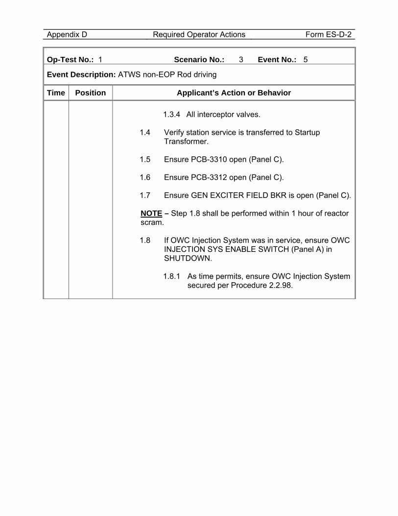
Appendix D Required Operator Actions Form ES-D-2
Op-Test No.: 1 Scenario No.: 3 Event No.: 5
Event Description: ATWS non-EOP Rod driving
Time Position Applicant’s Action or Behavior 1.3.4 All interceptor valves.
1.4 Verify station service is transferred to Startup
Transformer. 1.5 Ensure PCB-3310 open (Panel C). 1.6 Ensure PCB-3312 open (Panel C). 1.7 Ensure GEN EXCITER FIELD BKR is open (Panel C).
NOTE – Step 1.8 shall be performed within 1 hour of reactor
scram.
1.8 If OWC Injection System was in service, ensure OWC INJECTION SYS ENABLE SWITCH (Panel A) in SHUTDOWN.
1.8.1 As time permits, ensure OWC Injection System
secured per Procedure 2.2.98.
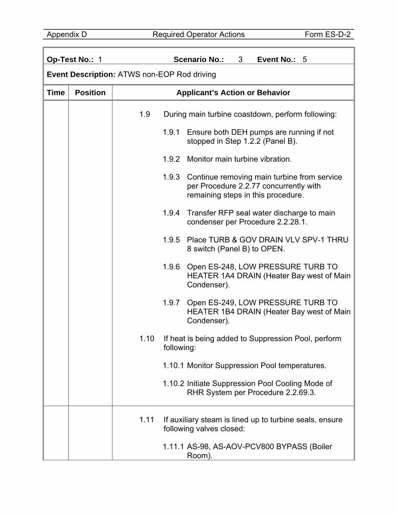
Appendix D Required Operator Actions Form ES-D-2
Op-Test No.: 1 Scenario No.: 3 Event No.: 5
Event Description: ATWS non-EOP Rod driving
Time Position Applicant’s Action or Behavior
1.9 During main turbine coastdown, perform following:
1.9.1 Ensure both DEH pumps are running if not stopped in Step 1.2.2 (Panel B).
1.9.2 Monitor main turbine vibration. 1.9.3 Continue removing main turbine from service
per Procedure 2.2.77 concurrently with remaining steps in this procedure.
1.9.4 Transfer RFP seal water discharge to main
condenser per Procedure 2.2.28.1. 1.9.5 Place TURB & GOV DRAIN VLV SPV-1 THRU
8 switch (Panel B) to OPEN. 1.9.6 Open ES-248, LOW PRESSURE TURB TO
HEATER 1A4 DRAIN (Heater Bay west of Main Condenser).
1.9.7 Open ES-249, LOW PRESSURE TURB TO
HEATER 1B4 DRAIN (Heater Bay west of Main Condenser).
1.10 If heat is being added to Suppression Pool, perform
following:
1.10.1 Monitor Suppression Pool temperatures. 1.10.2 Initiate Suppression Pool Cooling Mode of
RHR System per Procedure 2.2.69.3.
1.11 If auxiliary steam is lined up to turbine seals, ensure
following valves closed:
1.11.1 AS-98, AS-AOV-PCV800 BYPASS (Boiler Room).
Appendix D Required Operator Actions Form ES-D-2
Op-Test No.: 1 Scenario No.: 3 Event No.: 5
Event Description: ATWS non-EOP Rod driving
Time Position Applicant’s Action or Behavior 1.11.2 AS-32, AS-AOV-PCV801 BYPASS (R-903-
NE).
1.11.3 AS-55, AS-AOV-PCV802 BYPASS (T-903-Corridor North).
Appendix D Required Operator Actions Form ES-D-2
Op-Test No.: 1 Scenario No.: 3 Event No.: 5
Event Description: ATWS non-EOP Rod driving
Time Position Applicant’s Action or Behavior
BOP/RO Report rising drywell and main steam line radiation levels.
CRS
Enter Procedure 5.2FUEL FUEL FAILURE 1.ENTRY CONDITIONS
1.1 Unexplained rise in main steam line radiation. 1.2 Unexplained changes in core parameters (i.e., power,
pressure, or core flow). 1.3 Unexplained significant rise in plant background or
airborne radioactivity (CAM). 1.4 Irradiated fuel damage with release of radioactivity to
secondary containment as indicated by HIGH alarm on refueling floor ARM #2, CAM, or Reactor Building ventilation monitor.
CRS Direct 5.2FUEL actions taken.
BOP
Perform actions of 5.2FUEL 4.SUBSEQUENT OPERATOR ACTIONS
4.1 Lower power, as required, to reduce off-gas and main steam line radiation levels.
4.2 Check OWC Injection System for proper operation. 4.3 If valid MAIN STM LINE HI HI RAD (9-4-1/A-4) alarm is
actuated, SCRAM and enter Procedure 2.1.5. 4.4 If OFF-GAS TIMER INITIATED (9-4-1/C-4) alarm is
actuated, concurrently enter Procedure 2.4OG. 4.5 If valid MAIN STM LINE HI HI RAD (9-4-1/A-4) alarm is
actuated and reactor is shut down, then close MSIVs and MSL drain valves.
4.6 Direct Chemistry to sample reactor coolant activity. 4.7 Notify Reactor Engineering and follow their
recommendations per Procedure 10.31. 4.8 Check following indications for any unexplained
changes:
Appendix D Required Operator Actions Form ES-D-2
Op-Test No.: 1 Scenario No.: 3 Event No.: 5
Event Description: ATWS non-EOP Rod driving
Time Position Applicant’s Action or Behavior 4.8.1 LPRMs. 4.8.2 Off-gas flow to determine if holdup time has
changed. 4.8.3 Core pressure drop. 4.8.4 Individual jet pump ∆Ps when compared to
previous readings. 4.8.5 RR loop flows.
4.9 Annotate following recorders/displays with time and date: 4.9.1 AR-FR-47, SJAE AIR FLOW (PANEL B). 4.9.2 RMV-RR-3, RB/ERP/TB/RW/ARW RM RECORDER
(VBD-Q). 4.9.3 RMP-RR-152, OFF GAS RADIATION RECORDER
(PNL 9-02). 4.9.4 If AOG in service, at AOGCRP:
4.9.4.1 FR-101, FLOW RECORDER. 4.9.4.2 TR-102, TEMPERATURE RECORDER. 4.9.4.3 TR-103, TEMPERATURE RECORDER. 4.9.4.4 H2R-2024, DRYER OUTLET GAS HYDROGEN
CONTENT. 4.9.4.5 MR-2023, DRYER OUTLET GAS MOISTURE
CONTENT. NOTE – SLC System injection is required to be initiated within 6 hours and complete injection within 8 hours following a Design Basis LOCA to support AST LOCA Analysis.
4.10 If both following conditions exist, inject STANDBY LIQUID CONTROL per Procedure 2.2.74: 1,3
4.10.1 Drywell pressure > 1.84 psig. 4.10.2 Drywell radiation monitor > 250 R/hr during LOCA
conditions.
Appendix D Required Operator Actions Form ES-D-2
Op-Test No.: 1 Scenario No.: 3 Event No.: 5
Event Description: ATWS non-EOP Rod driving
Time Position Applicant’s Action or Behavior
4.11 If all following conditions exist, concurrently perform Attachment 1 (Page 4):
4.11.1 Drywell pressure > 1.84 psig. 4.11.2 Drywell radiation monitor > 250 R/hr during LOCA
conditions. 4.11.3 At least one MSIV in each MSL closed.
4.12 If one or more of the following exist at any time, concurrently perform Attachment 2 (Page 8).
4.12.1 Off-Gas Radiation Monitor (RMP-RM-150A(B) ≥ 1500 mr/hr.
4.12.2 Valid MAIN STM LINE HI HI RAD alarm (Annunciator 9-4-1/A-4).
4.12.3 Drywell Radiation Monitor > 250 R/hr during LOCA conditions.
4.12.4 Coolant sample activity > 4.0 µCi/gm, DOSE EQUIVALENT I-131.
Perform 5.2FUEL Attachment 2 actions if required: 1.Place following sump pumps to OFF (VBD-S):
1.1 Both Reactor Building Floor Drain Sump A pumps. 1.1.1 SUMP PUMP A-1. 1.1.2 SUMP PUMP A-2.
1.2 Both Reactor Building Floor Drain Sump B pumps. 1.2.1 SUMP PUMP B-1. 1.2.2 SUMP PUMP B-2.
1.3 Both Reactor Building Floor Drain Sump C pumps. 1.3.1 SUMP PUMP C-1. 1.3.2 SUMP PUMP C-2.
1.4 Both Reactor Building Floor Drain Sump D pumps. 1.4.1 SUMP PUMP D-1. 1.4.2 SUMP PUMP D-2.
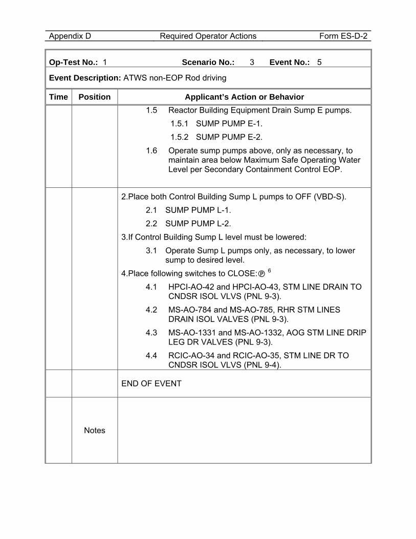
Appendix D Required Operator Actions Form ES-D-2
Op-Test No.: 1 Scenario No.: 3 Event No.: 5
Event Description: ATWS non-EOP Rod driving
Time Position Applicant’s Action or Behavior 1.5 Reactor Building Equipment Drain Sump E pumps.
1.5.1 SUMP PUMP E-1. 1.5.2 SUMP PUMP E-2.
1.6 Operate sump pumps above, only as necessary, to maintain area below Maximum Safe Operating Water Level per Secondary Containment Control EOP.
2.Place both Control Building Sump L pumps to OFF (VBD-S). 2.1 SUMP PUMP L-1. 2.2 SUMP PUMP L-2.
3.If Control Building Sump L level must be lowered: 3.1 Operate Sump L pumps only, as necessary, to lower
sump to desired level. 4.Place following switches to CLOSE: 6
4.1 HPCI-AO-42 and HPCI-AO-43, STM LINE DRAIN TO CNDSR ISOL VLVS (PNL 9-3).
4.2 MS-AO-784 and MS-AO-785, RHR STM LINES DRAIN ISOL VALVES (PNL 9-3).
4.3 MS-AO-1331 and MS-AO-1332, AOG STM LINE DRIP LEG DR VALVES (PNL 9-3).
4.4 RCIC-AO-34 and RCIC-AO-35, STM LINE DR TO CNDSR ISOL VLVS (PNL 9-4).
END OF EVENT
Notes
Appendix D Required Operator Actions Form ES-D-2
Op-Test No.: 1 Scenario No.: 3 Event No.: 5
Event Description: ATWS non-EOP Rod driving
Time Position Applicant’s Action or Behavior
Proceed to the next event at direction of the lead examiner.
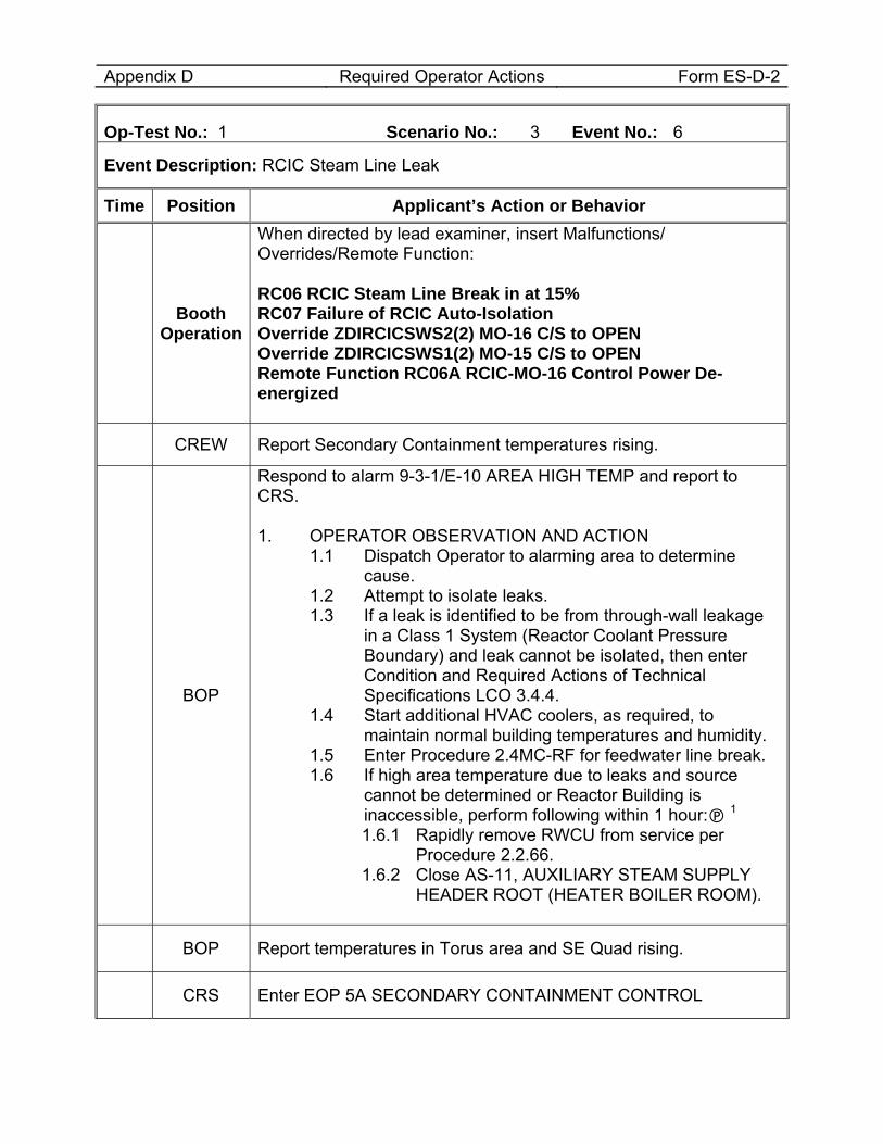
Appendix D Required Operator Actions Form ES-D-2
Op-Test No.: 1 Scenario No.: 3 Event No.: 6
Event Description: RCIC Steam Line Leak
Time Position Applicant’s Action or Behavior
Booth Operation
When directed by lead examiner, insert Malfunctions/ Overrides/Remote Function: RC06 RCIC Steam Line Break in at 15% RC07 Failure of RCIC Auto-Isolation Override ZDIRCICSWS2(2) MO-16 C/S to OPEN Override ZDIRCICSWS1(2) MO-15 C/S to OPEN Remote Function RC06A RCIC-MO-16 Control Power De-energized
CREW Report Secondary Containment temperatures rising.
BOP
Respond to alarm 9-3-1/E-10 AREA HIGH TEMP and report to CRS. 1. OPERATOR OBSERVATION AND ACTION
1.1 Dispatch Operator to alarming area to determine cause.
1.2 Attempt to isolate leaks. 1.3 If a leak is identified to be from through-wall leakage
in a Class 1 System (Reactor Coolant Pressure Boundary) and leak cannot be isolated, then enter Condition and Required Actions of Technical Specifications LCO 3.4.4.
1.4 Start additional HVAC coolers, as required, to maintain normal building temperatures and humidity.
1.5 Enter Procedure 2.4MC-RF for feedwater line break. 1.6 If high area temperature due to leaks and source
cannot be determined or Reactor Building is inaccessible, perform following within 1 hour: 1 1.6.1 Rapidly remove RWCU from service per
Procedure 2.2.66. 1.6.2 Close AS-11, AUXILIARY STEAM SUPPLY
HEADER ROOT (HEATER BOILER ROOM).
BOP Report temperatures in Torus area and SE Quad rising.
CRS Enter EOP 5A SECONDARY CONTAINMENT CONTROL
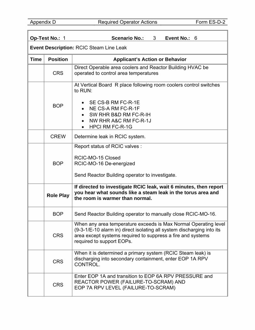
Appendix D Required Operator Actions Form ES-D-2
Op-Test No.: 1 Scenario No.: 3 Event No.: 6
Event Description: RCIC Steam Line Leak
Time Position Applicant’s Action or Behavior
CRS Direct Operable area coolers and Reactor Building HVAC be operated to control area temperatures
BOP
At Vertical Board R place following room coolers control switches to RUN:
• SE CS-B RM FC-R-1E • NE CS-A RM FC-R-1F • SW RHR B&D RM FC-R-IH • NW RHR A&C RM FC-R-1J • HPCI RM FC-R-1G
CREW Determine leak in RCIC system.
BOP
Report status of RCIC valves : RCIC-MO-15 Closed RCIC-MO-16 De-energized Send Reactor Building operator to investigate.
Role Play If directed to investigate RCIC leak, wait 6 minutes, then report you hear what sounds like a steam leak in the torus area and the room is warmer than normal.
BOP Send Reactor Building operator to manually close RCIC-MO-16.
CRS
When any area temperature exceeds is Max Normal Operating level (9-3-1/E-10 alarm in) direct isolating all system discharging into its area except systems required to suppress a fire and systems required to support EOPs.
CRS
When it is determined a primary system (RCIC Steam leak) is discharging into secondary containment, enter EOP 1A RPV CONTROL.
CRS
Enter EOP 1A and transition to EOP 6A RPV PRESSURE and REACTOR POWER (FAILURE-TO-SCRAM) AND EOP 7A RPV LEVEL (FAILURE-TO-SCRAM)
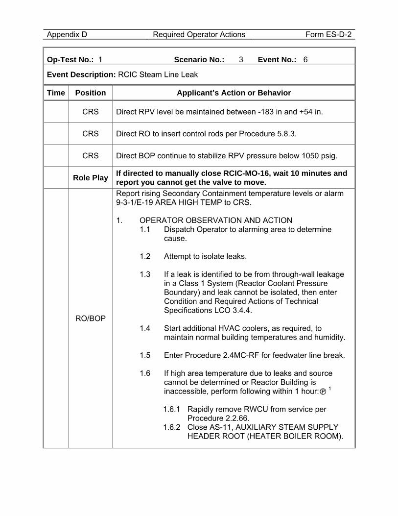
Appendix D Required Operator Actions Form ES-D-2
Op-Test No.: 1 Scenario No.: 3 Event No.: 6
Event Description: RCIC Steam Line Leak
Time Position Applicant’s Action or Behavior
CRS Direct RPV level be maintained between -183 in and +54 in.
CRS Direct RO to insert control rods per Procedure 5.8.3.
CRS Direct BOP continue to stabilize RPV pressure below 1050 psig.
Role Play If directed to manually close RCIC-MO-16, wait 10 minutes and report you cannot get the valve to move.
RO/BOP
Report rising Secondary Containment temperature levels or alarm 9-3-1/E-19 AREA HIGH TEMP to CRS. 1. OPERATOR OBSERVATION AND ACTION
1.1 Dispatch Operator to alarming area to determine cause.
1.2 Attempt to isolate leaks. 1.3 If a leak is identified to be from through-wall leakage
in a Class 1 System (Reactor Coolant Pressure Boundary) and leak cannot be isolated, then enter Condition and Required Actions of Technical Specifications LCO 3.4.4.
1.4 Start additional HVAC coolers, as required, to
maintain normal building temperatures and humidity. 1.5 Enter Procedure 2.4MC-RF for feedwater line break. 1.6 If high area temperature due to leaks and source
cannot be determined or Reactor Building is inaccessible, perform following within 1 hour: 1
1.6.1 Rapidly remove RWCU from service per
Procedure 2.2.66. 1.6.2 Close AS-11, AUXILIARY STEAM SUPPLY
HEADER ROOT (HEATER BOILER ROOM).
Appendix D Required Operator Actions Form ES-D-2
Op-Test No.: 1 Scenario No.: 3 Event No.: 6
Event Description: RCIC Steam Line Leak
Time Position Applicant’s Action or Behavior
END OF EVENT
Notes
Note to Examiner the next event (Group 6 failure) is already active.
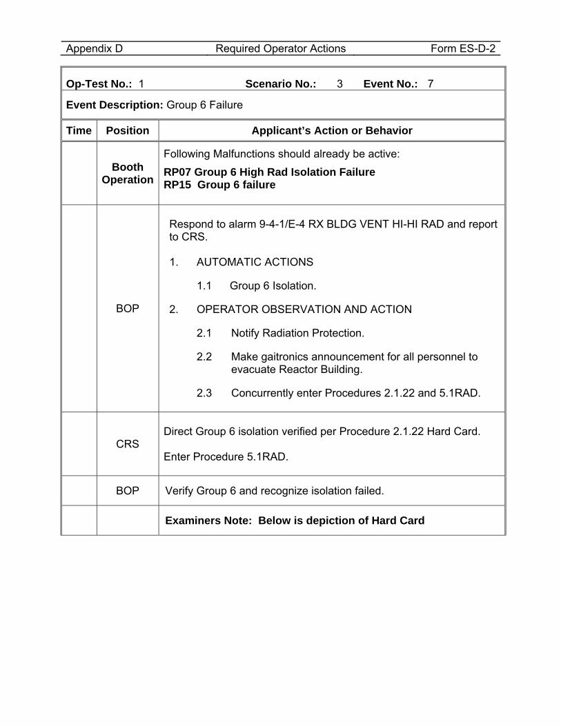
Appendix D Required Operator Actions Form ES-D-2
Op-Test No.: 1 Scenario No.: 3 Event No.: 7
Event Description: Group 6 Failure
Time Position Applicant’s Action or Behavior
Booth Operation
Following Malfunctions should already be active: RP07 Group 6 High Rad Isolation Failure RP15 Group 6 failure
BOP
Respond to alarm 9-4-1/E-4 RX BLDG VENT HI-HI RAD and report to CRS. 1. AUTOMATIC ACTIONS
1.1 Group 6 Isolation.
2. OPERATOR OBSERVATION AND ACTION
2.1 Notify Radiation Protection.
2.2 Make gaitronics announcement for all personnel to evacuate Reactor Building.
2.3 Concurrently enter Procedures 2.1.22 and 5.1RAD.
CRS
Direct Group 6 isolation verified per Procedure 2.1.22 Hard Card. Enter Procedure 5.1RAD.
BOP Verify Group 6 and recognize isolation failed.
Examiners Note: Below is depiction of Hard Card
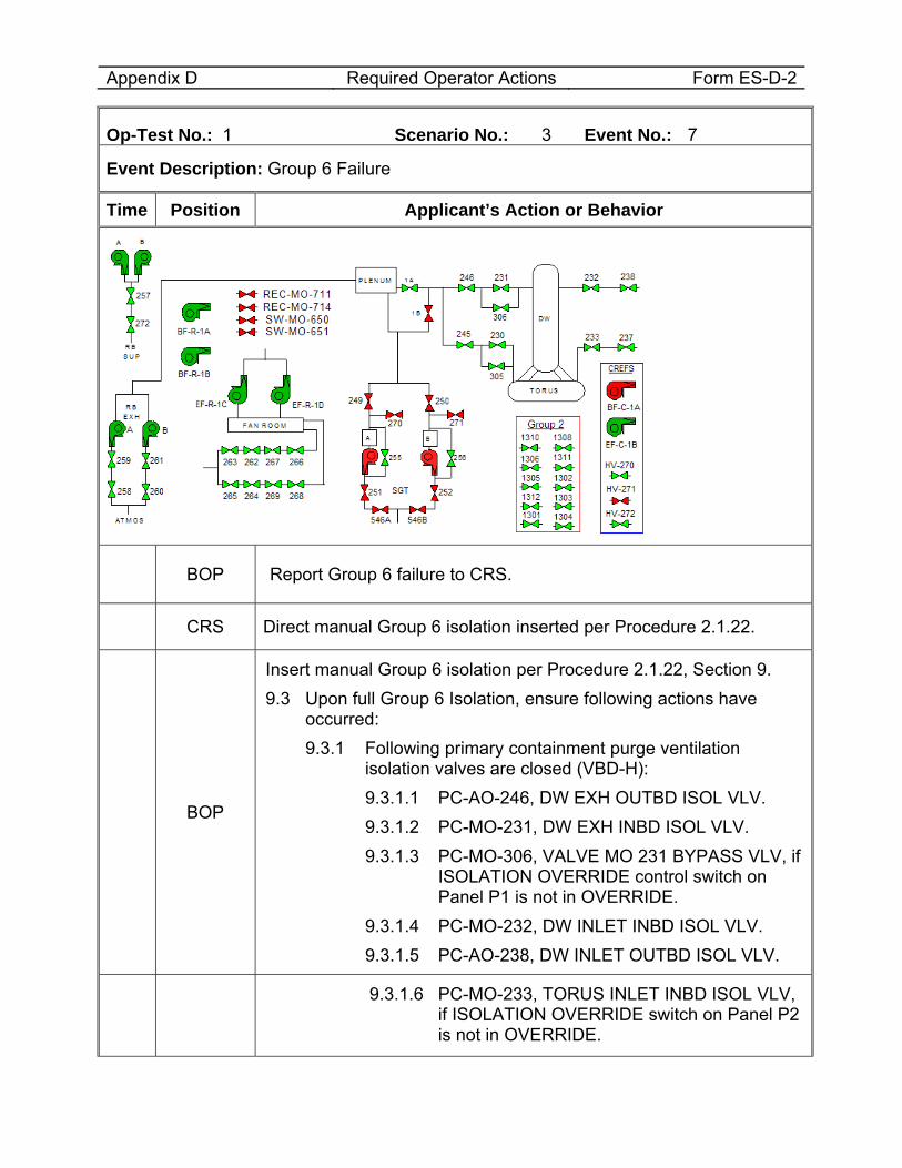
Appendix D Required Operator Actions Form ES-D-2
Op-Test No.: 1 Scenario No.: 3 Event No.: 7
Event Description: Group 6 Failure
Time Position Applicant’s Action or Behavior
BOP Report Group 6 failure to CRS.
CRS Direct manual Group 6 isolation inserted per Procedure 2.1.22.
BOP
Insert manual Group 6 isolation per Procedure 2.1.22, Section 9. 9.3 Upon full Group 6 Isolation, ensure following actions have
occurred: 9.3.1 Following primary containment purge ventilation
isolation valves are closed (VBD-H): 9.3.1.1 PC-AO-246, DW EXH OUTBD ISOL VLV. 9.3.1.2 PC-MO-231, DW EXH INBD ISOL VLV. 9.3.1.3 PC-MO-306, VALVE MO 231 BYPASS VLV, if
ISOLATION OVERRIDE control switch on Panel P1 is not in OVERRIDE.
9.3.1.4 PC-MO-232, DW INLET INBD ISOL VLV. 9.3.1.5 PC-AO-238, DW INLET OUTBD ISOL VLV.
9.3.1.6 PC-MO-233, TORUS INLET INBD ISOL VLV, if ISOLATION OVERRIDE switch on Panel P2 is not in OVERRIDE.
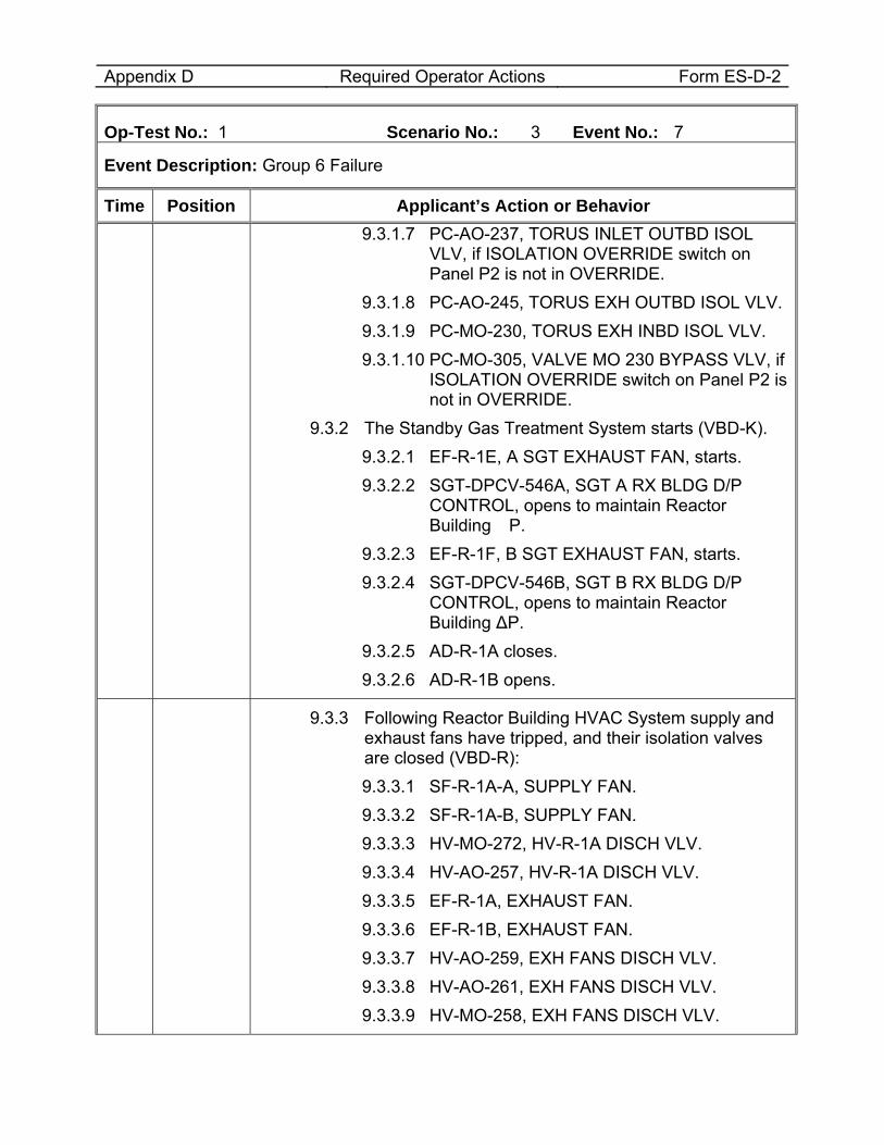
Appendix D Required Operator Actions Form ES-D-2
Op-Test No.: 1 Scenario No.: 3 Event No.: 7
Event Description: Group 6 Failure
Time Position Applicant’s Action or Behavior 9.3.1.7 PC-AO-237, TORUS INLET OUTBD ISOL
VLV, if ISOLATION OVERRIDE switch on Panel P2 is not in OVERRIDE.
9.3.1.8 PC-AO-245, TORUS EXH OUTBD ISOL VLV. 9.3.1.9 PC-MO-230, TORUS EXH INBD ISOL VLV. 9.3.1.10 PC-MO-305, VALVE MO 230 BYPASS VLV, if
ISOLATION OVERRIDE switch on Panel P2 is not in OVERRIDE.
9.3.2 The Standby Gas Treatment System starts (VBD-K). 9.3.2.1 EF-R-1E, A SGT EXHAUST FAN, starts. 9.3.2.2 SGT-DPCV-546A, SGT A RX BLDG D/P
CONTROL, opens to maintain Reactor Building �P.
9.3.2.3 EF-R-1F, B SGT EXHAUST FAN, starts. 9.3.2.4 SGT-DPCV-546B, SGT B RX BLDG D/P
CONTROL, opens to maintain Reactor Building ∆P.
9.3.2.5 AD-R-1A closes. 9.3.2.6 AD-R-1B opens.
9.3.3 Following Reactor Building HVAC System supply and exhaust fans have tripped, and their isolation valves are closed (VBD-R): 9.3.3.1 SF-R-1A-A, SUPPLY FAN. 9.3.3.2 SF-R-1A-B, SUPPLY FAN. 9.3.3.3 HV-MO-272, HV-R-1A DISCH VLV. 9.3.3.4 HV-AO-257, HV-R-1A DISCH VLV. 9.3.3.5 EF-R-1A, EXHAUST FAN. 9.3.3.6 EF-R-1B, EXHAUST FAN. 9.3.3.7 HV-AO-259, EXH FANS DISCH VLV. 9.3.3.8 HV-AO-261, EXH FANS DISCH VLV. 9.3.3.9 HV-MO-258, EXH FANS DISCH VLV.
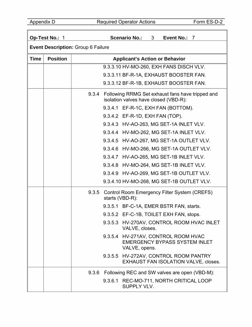
Appendix D Required Operator Actions Form ES-D-2
Op-Test No.: 1 Scenario No.: 3 Event No.: 7
Event Description: Group 6 Failure
Time Position Applicant’s Action or Behavior 9.3.3.10 HV-MO-260, EXH FANS DISCH VLV. 9.3.3.11 BF-R-1A, EXHAUST BOOSTER FAN. 9.3.3.12 BF-R-1B, EXHAUST BOOSTER FAN.
9.3.4 Following RRMG Set exhaust fans have tripped and isolation valves have closed (VBD-R): 9.3.4.1 EF-R-1C, EXH FAN (BOTTOM). 9.3.4.2 EF-R-1D, EXH FAN (TOP). 9.3.4.3 HV-AO-263, MG SET-1A INLET VLV. 9.3.4.4 HV-MO-262, MG SET-1A INLET VLV. 9.3.4.5 HV-AO-267, MG SET-1A OUTLET VLV. 9.3.4.6 HV-MO-266, MG SET-1A OUTLET VLV. 9.3.4.7 HV-AO-265, MG SET-1B INLET VLV. 9.3.4.8 HV-MO-264, MG SET-1B INLET VLV. 9.3.4.9 HV-AO-269, MG SET-1B OUTLET VLV. 9.3.4.10 HV-MO-268, MG SET-1B OUTLET VLV.
9.3.5 Control Room Emergency Filter System (CREFS) starts (VBD-R): 9.3.5.1 BF-C-1A, EMER BSTR FAN, starts. 9.3.5.2 EF-C-1B, TOILET EXH FAN, stops. 9.3.5.3 HV-270AV, CONTROL ROOM HVAC INLET
VALVE, closes. 9.3.5.4 HV-271AV, CONTROL ROOM HVAC
EMERGENCY BYPASS SYSTEM INLET VALVE, opens.
9.3.5.5 HV-272AV, CONTROL ROOM PANTRY EXHAUST FAN ISOLATION VALVE, closes.
9.3.6 Following REC and SW valves are open (VBD-M): 9.3.6.1 REC-MO-711, NORTH CRITICAL LOOP
SUPPLY VLV.
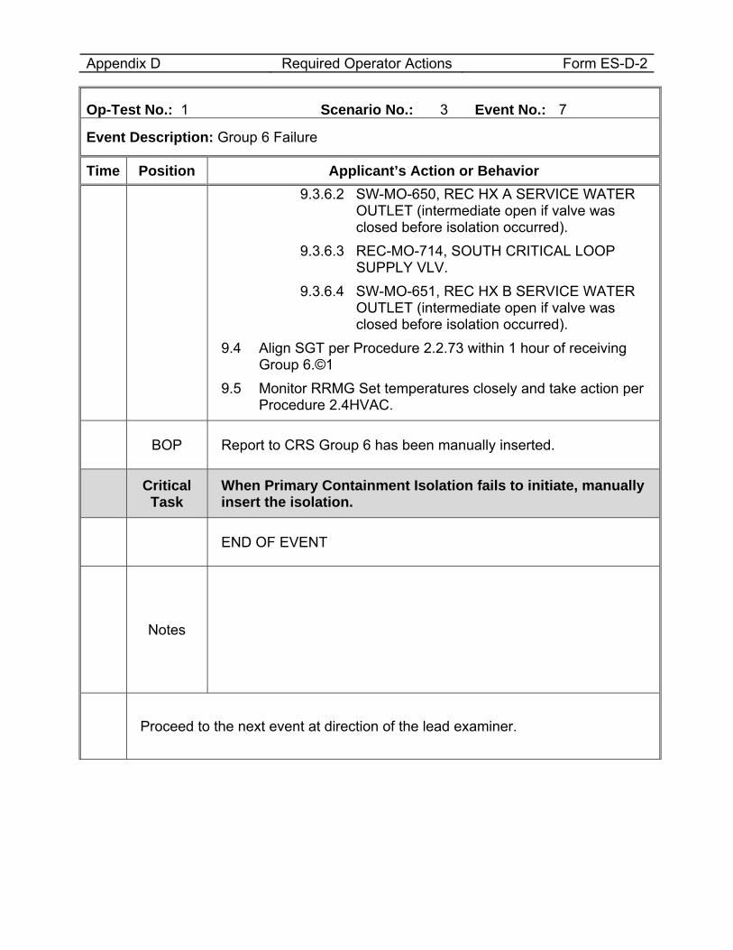
Appendix D Required Operator Actions Form ES-D-2
Op-Test No.: 1 Scenario No.: 3 Event No.: 7
Event Description: Group 6 Failure
Time Position Applicant’s Action or Behavior 9.3.6.2 SW-MO-650, REC HX A SERVICE WATER
OUTLET (intermediate open if valve was closed before isolation occurred).
9.3.6.3 REC-MO-714, SOUTH CRITICAL LOOP SUPPLY VLV.
9.3.6.4 SW-MO-651, REC HX B SERVICE WATER OUTLET (intermediate open if valve was closed before isolation occurred).
9.4 Align SGT per Procedure 2.2.73 within 1 hour of receiving Group 6.©1
9.5 Monitor RRMG Set temperatures closely and take action per Procedure 2.4HVAC.
BOP Report to CRS Group 6 has been manually inserted.
Critical Task
When Primary Containment Isolation fails to initiate, manually insert the isolation.
END OF EVENT
Notes
Proceed to the next event at direction of the lead examiner.
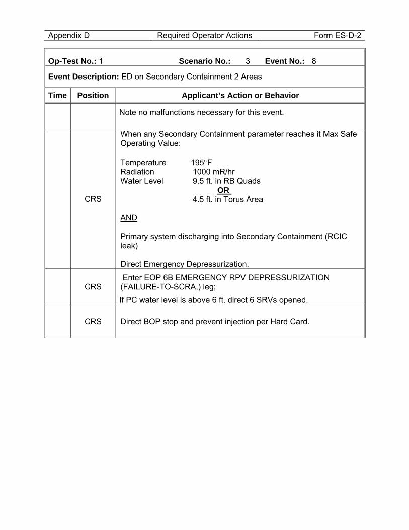
Appendix D Required Operator Actions Form ES-D-2
Op-Test No.: 1 Scenario No.: 3 Event No.: 8
Event Description: ED on Secondary Containment 2 Areas
Time Position Applicant’s Action or Behavior
Note no malfunctions necessary for this event.
CRS
When any Secondary Containment parameter reaches it Max Safe Operating Value: Temperature 195°F Radiation 1000 mR/hr Water Level 9.5 ft. in RB Quads OR 4.5 ft. in Torus Area AND Primary system discharging into Secondary Containment (RCIC leak) Direct Emergency Depressurization.
CRS Enter EOP 6B EMERGENCY RPV DEPRESSURIZATION (FAILURE-TO-SCRA,) leg; If PC water level is above 6 ft. direct 6 SRVs opened.
CRS Direct BOP stop and prevent injection per Hard Card.
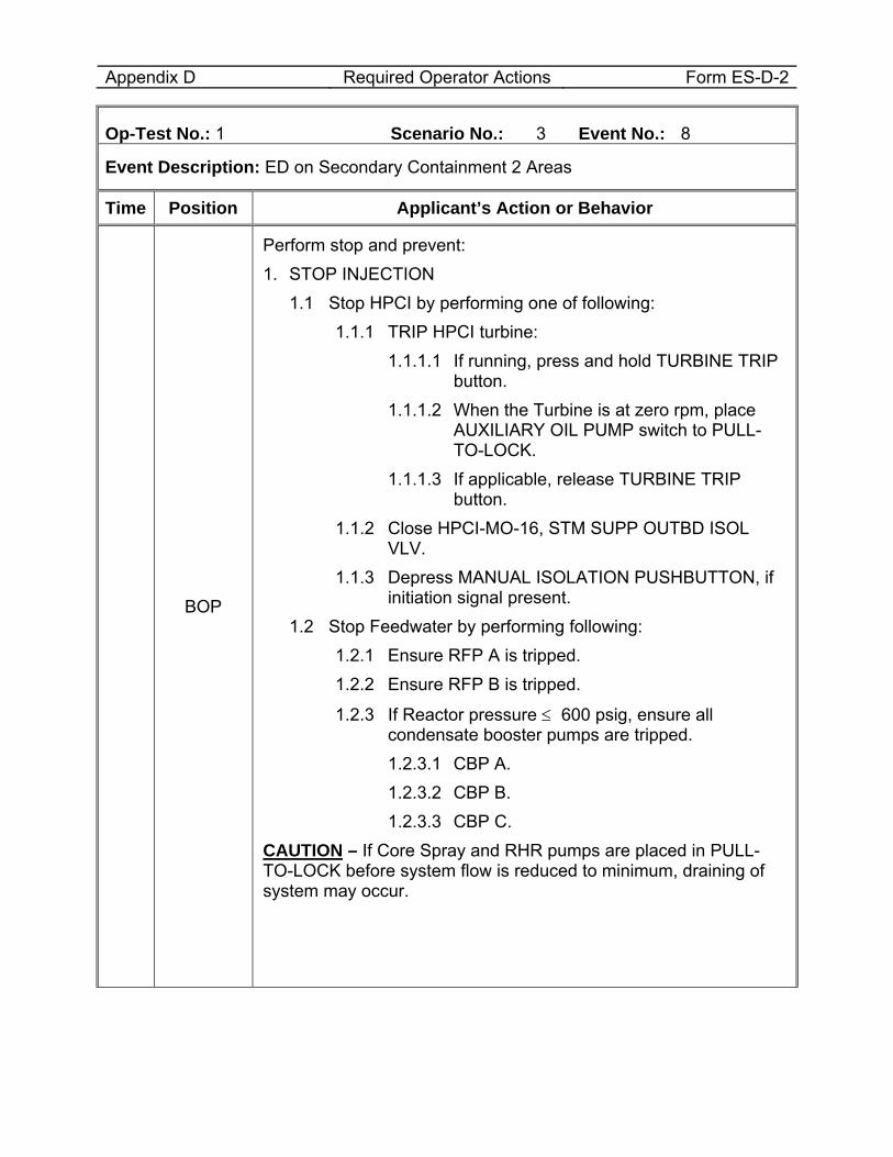
Appendix D Required Operator Actions Form ES-D-2
Op-Test No.: 1 Scenario No.: 3 Event No.: 8
Event Description: ED on Secondary Containment 2 Areas
Time Position Applicant’s Action or Behavior
BOP
Perform stop and prevent: 1. STOP INJECTION
1.1 Stop HPCI by performing one of following: 1.1.1 TRIP HPCI turbine:
1.1.1.1 If running, press and hold TURBINE TRIP button.
1.1.1.2 When the Turbine is at zero rpm, place AUXILIARY OIL PUMP switch to PULL-TO-LOCK.
1.1.1.3 If applicable, release TURBINE TRIP button.
1.1.2 Close HPCI-MO-16, STM SUPP OUTBD ISOL VLV.
1.1.3 Depress MANUAL ISOLATION PUSHBUTTON, if initiation signal present.
1.2 Stop Feedwater by performing following: 1.2.1 Ensure RFP A is tripped. 1.2.2 Ensure RFP B is tripped.
1.2.3 If Reactor pressure ≤ 600 psig, ensure all condensate booster pumps are tripped. 1.2.3.1 CBP A. 1.2.3.2 CBP B. 1.2.3.3 CBP C.
CAUTION – If Core Spray and RHR pumps are placed in PULL-TO-LOCK before system flow is reduced to minimum, draining of system may occur.
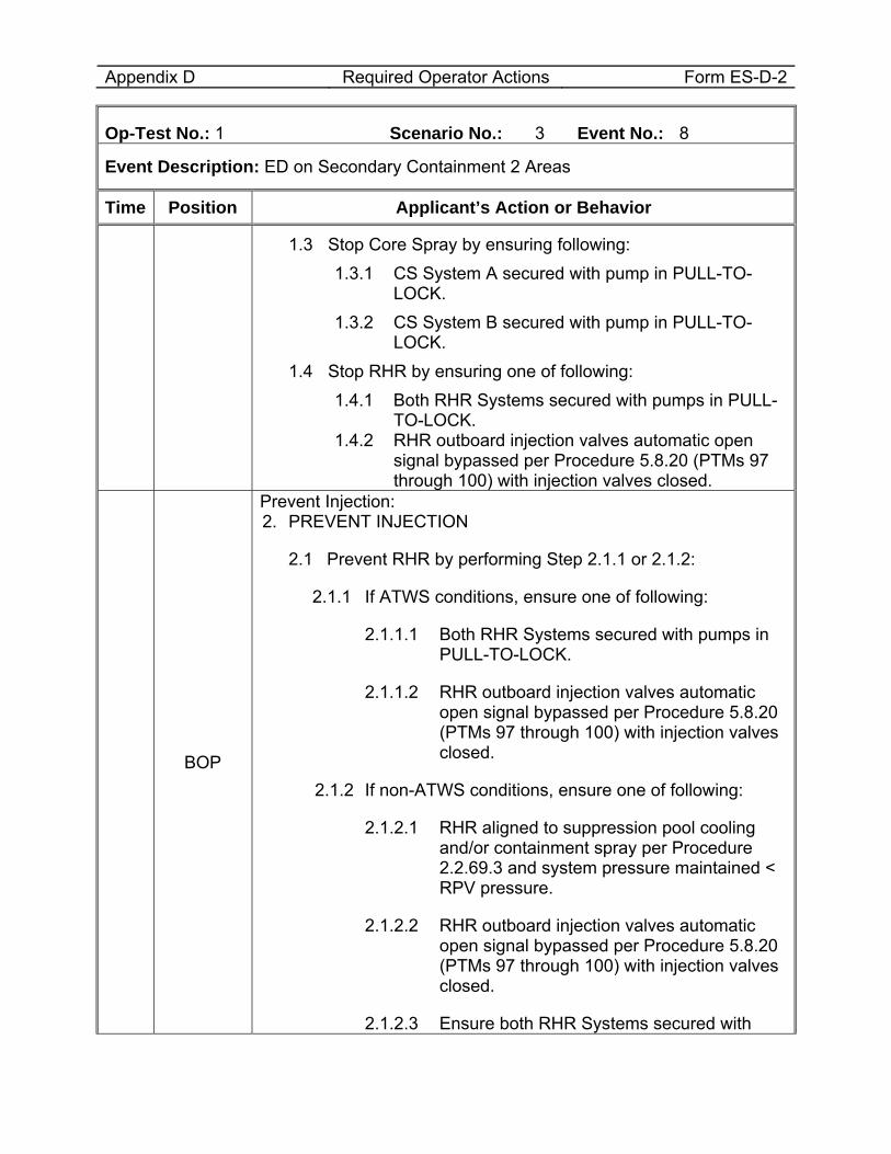
Appendix D Required Operator Actions Form ES-D-2
Op-Test No.: 1 Scenario No.: 3 Event No.: 8
Event Description: ED on Secondary Containment 2 Areas
Time Position Applicant’s Action or Behavior
1.3 Stop Core Spray by ensuring following: 1.3.1 CS System A secured with pump in PULL-TO-
LOCK. 1.3.2 CS System B secured with pump in PULL-TO-
LOCK. 1.4 Stop RHR by ensuring one of following:
1.4.1 Both RHR Systems secured with pumps in PULL-TO-LOCK.
1.4.2 RHR outboard injection valves automatic open signal bypassed per Procedure 5.8.20 (PTMs 97 through 100) with injection valves closed.
BOP
Prevent Injection: 2. PREVENT INJECTION
2.1 Prevent RHR by performing Step 2.1.1 or 2.1.2:
2.1.1 If ATWS conditions, ensure one of following:
2.1.1.1 Both RHR Systems secured with pumps in PULL-TO-LOCK.
2.1.1.2 RHR outboard injection valves automatic open signal bypassed per Procedure 5.8.20 (PTMs 97 through 100) with injection valves closed.
2.1.2 If non-ATWS conditions, ensure one of following:
2.1.2.1 RHR aligned to suppression pool cooling and/or containment spray per Procedure 2.2.69.3 and system pressure maintained < RPV pressure.
2.1.2.2 RHR outboard injection valves automatic open signal bypassed per Procedure 5.8.20 (PTMs 97 through 100) with injection valves closed.
2.1.2.3 Ensure both RHR Systems secured with
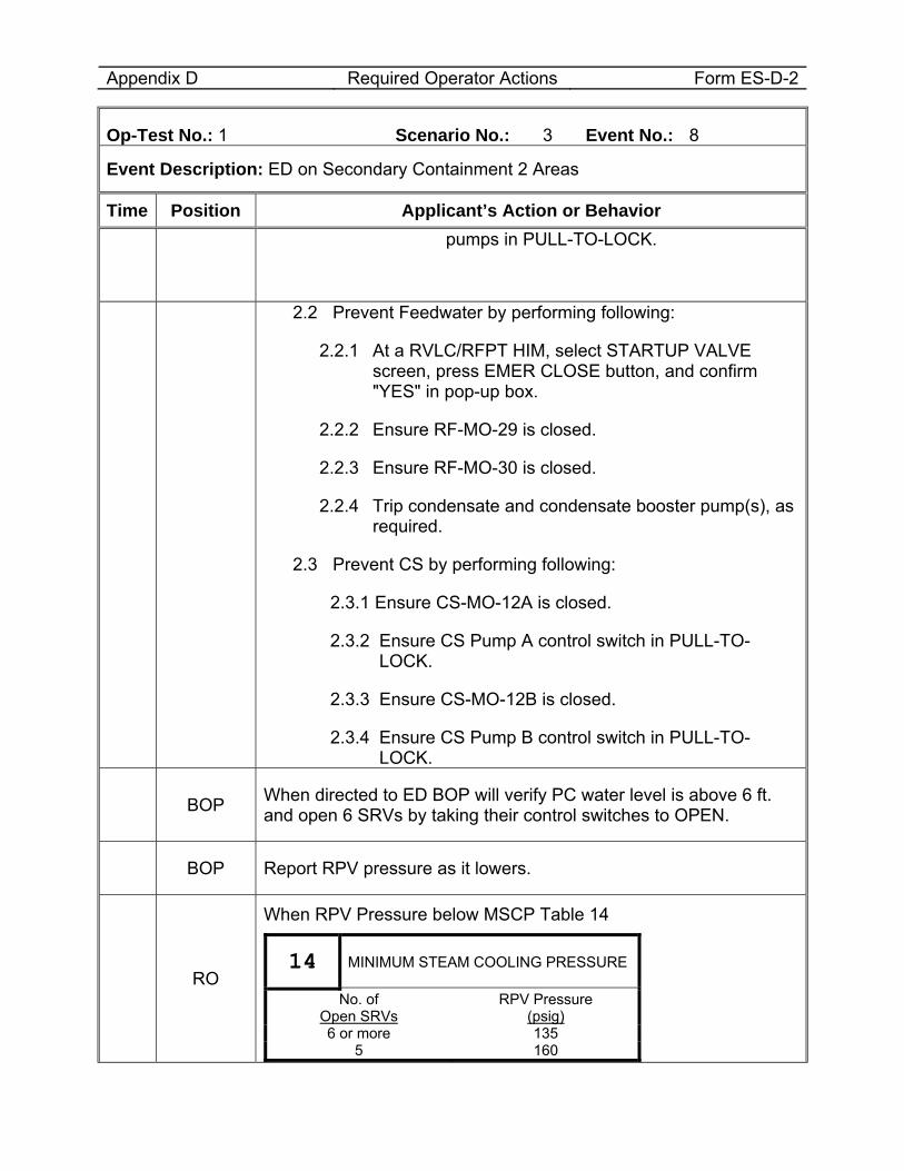
Appendix D Required Operator Actions Form ES-D-2
Op-Test No.: 1 Scenario No.: 3 Event No.: 8
Event Description: ED on Secondary Containment 2 Areas
Time Position Applicant’s Action or Behavior pumps in PULL-TO-LOCK.
2.2 Prevent Feedwater by performing following:
2.2.1 At a RVLC/RFPT HIM, select STARTUP VALVE screen, press EMER CLOSE button, and confirm "YES" in pop-up box.
2.2.2 Ensure RF-MO-29 is closed.
2.2.3 Ensure RF-MO-30 is closed.
2.2.4 Trip condensate and condensate booster pump(s), as required.
2.3 Prevent CS by performing following:
2.3.1 Ensure CS-MO-12A is closed.
2.3.2 Ensure CS Pump A control switch in PULL-TO-LOCK.
2.3.3 Ensure CS-MO-12B is closed.
2.3.4 Ensure CS Pump B control switch in PULL-TO-LOCK.
BOP When directed to ED BOP will verify PC water level is above 6 ft. and open 6 SRVs by taking their control switches to OPEN.
BOP Report RPV pressure as it lowers.
RO
When RPV Pressure below MSCP Table 14
14 MINIMUM STEAM COOLING PRESSURE
No. of Open SRVs
RPV Pressure (psig)
6 or more 135 5 160
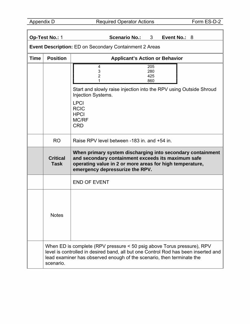
Appendix D Required Operator Actions Form ES-D-2
Op-Test No.: 1 Scenario No.: 3 Event No.: 8
Event Description: ED on Secondary Containment 2 Areas
Time Position Applicant’s Action or Behavior 4 205 3 280 2 425 1 860
Start and slowly raise injection into the RPV using Outside Shroud Injection Systems. LPCI RCIC HPCI MC/RF CRD
RO Raise RPV level between -183 in. and +54 in.
Critical Task
When primary system discharging into secondary containment and secondary containment exceeds its maximum safe operating value in 2 or more areas for high temperature, emergency depressurize the RPV.
END OF EVENT
Notes
When ED is complete (RPV pressure < 50 psig above Torus pressure), RPV level is controlled in desired band, all but one Control Rod has been inserted and lead examiner has observed enough of the scenario, then terminate the scenario.
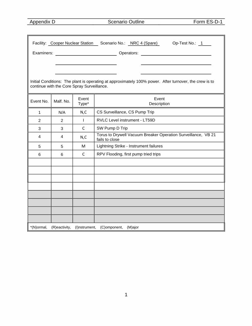
Appendix D Scenario Outline Form ES-D-1
1
Facility: Cooper Nuclear Station Scenario No.: NRC 4 (Spare) Op-Test No.: 1 Examiners: Operators:
Initial Conditions: The plant is operating at approximately 100% power. After turnover, the crew is to continue with the Core Spray Surveillance.
Event No. Malf. No. Event Type*
Event Description
1 N/A N,C CS Surveillance, CS Pump Trip
2 2 I RVLC Level instrument - LT59D
3 3 C SW Pump D Trip
4 4 N,C Torus to Drywell Vacuum Breaker Operation Surveillance, VB 21 fails to close
5 5 M Lightning Strike - Instrument failures
6 6 C RPV Flooding, first pump tried trips
*(N)ormal, (R)eactivity, (I)nstrument, (C)omponent, (M)ajor
Appendix D Scenario Outline Attachment 2
2
Scenario Objective Evaluate the crew’s ability to perform surveillance and normal operations and respond to instrument failure which has an input to the Reactor Vessel Level Control System. Evaluate the crew’s response to a loss of RPV level indication and entry into the RPV Flooding procedures. Evaluate CRS ability to determine Tech Spec LCOs are not met and take appropriate Required Actions .. Scenario Summary Initial Conditions: • 100% Power • Surveillance Procedure 6.1CS.101, CORE SPRAY TEST MODE SURVEILLANCE
OPERATION (IST) (DIV 1) (92 day) is due to be performed at the beginning of shift. Events: • CS Surveillance, CS Pump Trip • RVLC Level instrument - LT59D • SW Pump D Trip • Torus to Drywell Vacuum Breaker Operation Surveillance, NRV- 21 fails to close • Lightning Strike – Relay failure causes 161kV breaker trip. • RPV instrument failures cause RPV level to be unknown. • RPV Flooding, first pump tried trips
Scenario Sequence • Normal activity – CS Surveillance • Component Failure before EOPs – CS Pump Trip • Instrument Failure – RVLC Level instrument - LT59D • Component Failure before EOPs – SW Pump D Trip • Major Event – Lightning Strike - Instrument failures • Component Failure after EOPs – first pump tried trips • Accident mitigation strategy – RPV Flooding
Event One: CS Surveillance, CS Pump Trip Malfunction Required: CS01a Core Spray A pump trip. Objective:
Appendix D Scenario Outline Attachment 2
3
Evaluate the crew during normal equipment shifting. Evaluate the Balance of Plant Operator response to pump trip. Evaluate SRO Tech Spec entry for CS surveillance Success Path: The BOP reports trip to CRS. The SRO will address Tech Specs for inoperable subsystem and pump. Event Two: RVLC Level instrument - LT59D Malfunction Required: RR41d NBI-LT-59D (Wide Range Level) Failure set at 0%. Objective: Evaluate the crew’s response to the failure of a RVLC input. Evaluate the CRS addressing Technical Specifications. Success Path: The BOP Operator either responds . Event Three: SW Pump D Trip Malfunction Required: SW01d Service Water Pump Trip 1D Objective: Evaluate the crew’s response to a failed service water pump. Evaluate the At the Controls (ATC) Operator’s actions to start standby pump. Evaluate the CRS addressing Technical Specifications for the failed pump. Success Path: BOP starts standby pump. The SRO addresses Tech Specs and determines the SW pump is inoperable. Event Four: Torus to Drywell Vacuum Breaker Operation Surveillance, NRV-21 fails to close Malfunction Required: PC02b Torus To Drywell Vacuum Breaker Failure NRV-21 (open) set at 100% Objective: Evaluate the crew’s response to a vacuum breaker failing open. Evaluate the CRS addressing Technical Specifications for inoperable vacuum breaker. Success Path: The SRO addresses Tech Specs and declares the vacuum breaker inoperable.
Appendix D Scenario Outline Attachment 2
4
Event Five: Lightning Strike - Instrument failures Malfunctions Required: HV03 Lightning Strike RR33a Reference leg 3A failure set at 80%. RR44 NBI-LT-92 failure set at 80%. RR43 NBI-LT-61 failure set at 5%. RR42b NBI-LT-59b failure set at 20%. RR41a NBI-LT-59a failure set at 100. RR41c NBI-LT-59c failure set at 0. Overrides Required: RA:MUX00C071 set to ON (alarm 9-3-2/B-5 Low Level -113). RA:MUX00C028 set to ON (alarm 9-3-2/B-5 Low Level -113). RA:MUX00C024 set to ON (alarm 9-3-2/A-5 Low Level -42). 03M37 NBI-LI-94b failure set at 0. Objective: Evaluate the crew’s response to disparity in RPV level instrumentation. Evaluate the CRS decision to enter RPV flooding due to loss of RPV level instrumentation. Success Path: .The CRS enters EOP 2B and floods the RPV to the elevation of the Main Steam Lines.. Event Six: RPV Flooding, first pump tried trips Malfunction Required: CS01b Core Spray Pump B RH01a RHR Pump A RH01b RHR Pump B RH01c RHR Pump C RH01d RHR Pump D FW01a RF Pump A FW01b RF Pump B HP02 HPCI Pump RC02 RCIC Pump FW15a CBP A FW15b CBP B FW15c CBP C Objective: Evaluate the crew’s response to a failure of RPV level indication. Evaluate the BOP’s ability to monitor and control RPV injection to restore RPV level.
Appendix D Scenario Outline Attachment 2
5
Evaluate the crew’s ability to recognize the RPV is flooded to the Main Steam Lines.. Success Path: . The RPV core is covered by submergence evident by flooding to the MSL elevation. Scenario Termination: When RPV level reaches the elevation of the Main Steam Lines and injection into the RPV is maintaining flooding conditions with injection as low a practicable.
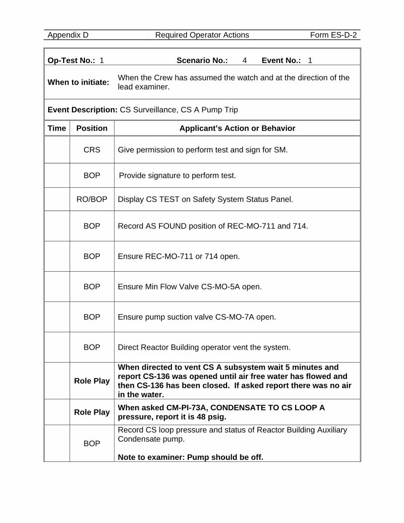
Appendix D Required Operator Actions Form ES-D-2
Op-Test No.: 1 Scenario No.: 4 Event No.: 1
When to initiate: When the Crew has assumed the watch and at the direction of the lead examiner.
Event Description: CS Surveillance, CS A Pump Trip
Time Position Applicant’s Action or Behavior
CRS Give permission to perform test and sign for SM.
BOP Provide signature to perform test.
RO/BOP Display CS TEST on Safety System Status Panel.
BOP Record AS FOUND position of REC-MO-711 and 714.
BOP Ensure REC-MO-711 or 714 open.
BOP Ensure Min Flow Valve CS-MO-5A open.
BOP Ensure pump suction valve CS-MO-7A open.
BOP Direct Reactor Building operator vent the system.
Role Play When directed to vent CS A subsystem wait 5 minutes and report CS-136 was opened until air free water has flowed and then CS-136 has been closed. If asked report there was no air in the water.
Role Play When asked CM-PI-73A, CONDENSATE TO CS LOOP A pressure, report it is 48 psig.
BOP
Record CS loop pressure and status of Reactor Building Auxiliary Condensate pump. Note to examiner: Pump should be off.
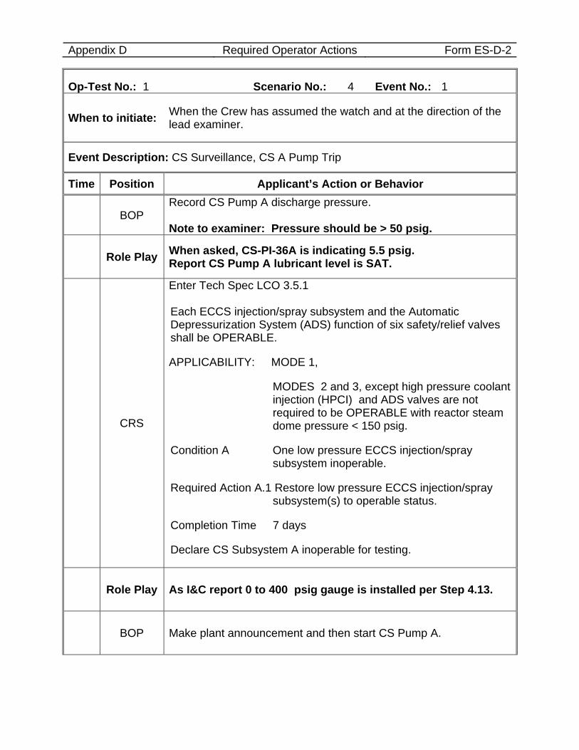
Appendix D Required Operator Actions Form ES-D-2
Op-Test No.: 1 Scenario No.: 4 Event No.: 1
When to initiate: When the Crew has assumed the watch and at the direction of the lead examiner.
Event Description: CS Surveillance, CS A Pump Trip
Time Position Applicant’s Action or Behavior
BOP Record CS Pump A discharge pressure. Note to examiner: Pressure should be > 50 psig.
Role Play When asked, CS-PI-36A is indicating 5.5 psig. Report CS Pump A lubricant level is SAT.
CRS
Enter Tech Spec LCO 3.5.1 Each ECCS injection/spray subsystem and the Automatic Depressurization System (ADS) function of six safety/relief valves shall be OPERABLE.
APPLICABILITY: MODE 1,
MODES 2 and 3, except high pressure coolant injection (HPCI) and ADS valves are not required to be OPERABLE with reactor steam dome pressure < 150 psig.
Condition A One low pressure ECCS injection/spray subsystem inoperable.
Required Action A.1 Restore low pressure ECCS injection/spray subsystem(s) to operable status.
Completion Time 7 days
Declare CS Subsystem A inoperable for testing.
Role Play As I&C report 0 to 400 psig gauge is installed per Step 4.13.
BOP Make plant announcement and then start CS Pump A.
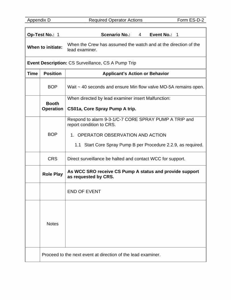
Appendix D Required Operator Actions Form ES-D-2
Op-Test No.: 1 Scenario No.: 4 Event No.: 1
When to initiate: When the Crew has assumed the watch and at the direction of the lead examiner.
Event Description: CS Surveillance, CS A Pump Trip
Time Position Applicant’s Action or Behavior
BOP Wait ~ 40 seconds and ensure Min flow valve MO-5A remains open.
Booth Operation
When directed by lead examiner insert Malfunction: CS01a, Core Spray Pump A trip.
BOP
Respond to alarm 9-3-1/C-7 CORE SPRAY PUMP A TRIP and report condition to CRS.
1. OPERATOR OBSERVATION AND ACTION
1.1 Start Core Spray Pump B per Procedure 2.2.9, as required.
CRS Direct surveillance be halted and contact WCC for support.
Role Play As WCC SRO receive CS Pump A status and provide support as requested by CRS.
END OF EVENT
Notes
Proceed to the next event at direction of the lead examiner.
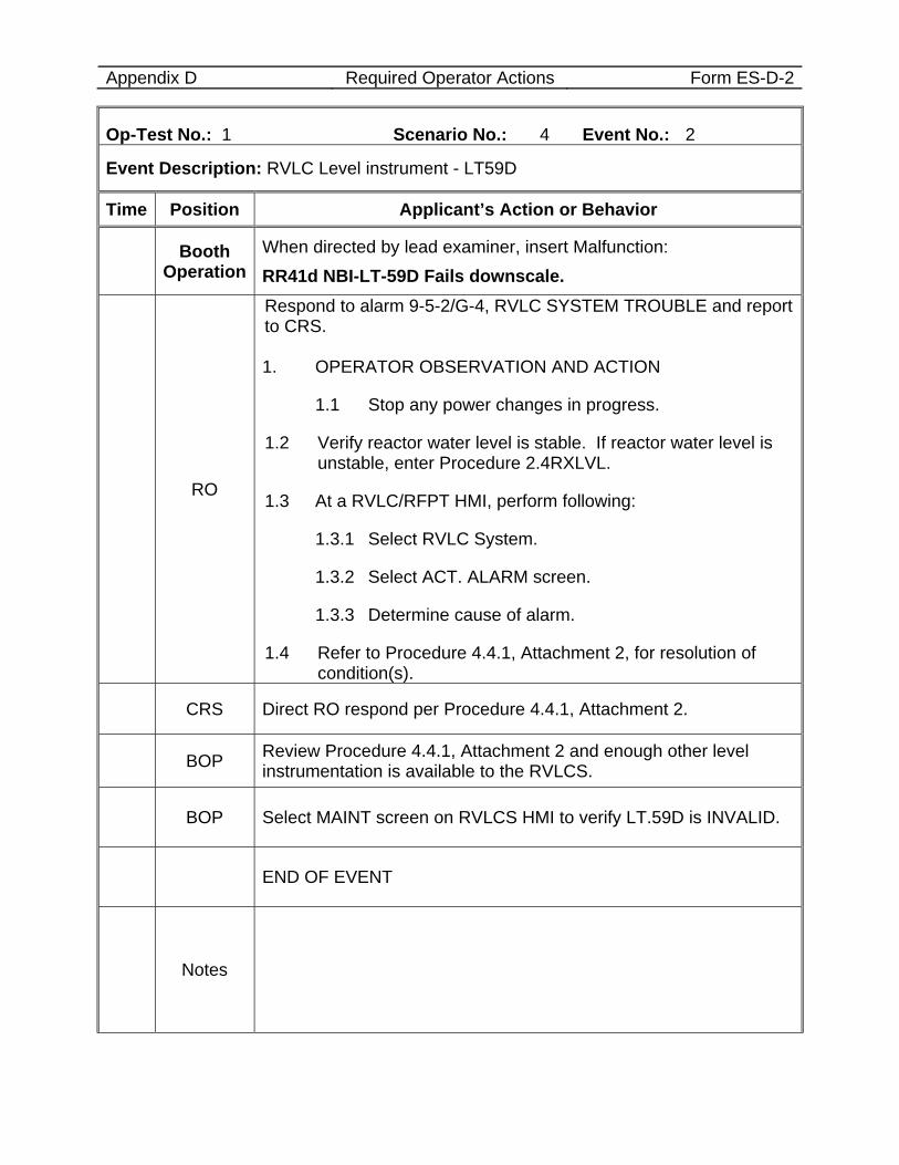
Appendix D Required Operator Actions Form ES-D-2
Op-Test No.: 1 Scenario No.: 4 Event No.: 2
Event Description: RVLC Level instrument - LT59D
Time Position Applicant’s Action or Behavior
Booth Operation
When directed by lead examiner, insert Malfunction: RR41d NBI-LT-59D Fails downscale.
RO
Respond to alarm 9-5-2/G-4, RVLC SYSTEM TROUBLE and report to CRS. 1. OPERATOR OBSERVATION AND ACTION
1.1 Stop any power changes in progress.
1.2 Verify reactor water level is stable. If reactor water level is unstable, enter Procedure 2.4RXLVL.
1.3 At a RVLC/RFPT HMI, perform following:
1.3.1 Select RVLC System.
1.3.2 Select ACT. ALARM screen.
1.3.3 Determine cause of alarm.
1.4 Refer to Procedure 4.4.1, Attachment 2, for resolution of condition(s).
CRS Direct RO respond per Procedure 4.4.1, Attachment 2.
BOP Review Procedure 4.4.1, Attachment 2 and enough other level instrumentation is available to the RVLCS.
BOP Select MAINT screen on RVLCS HMI to verify LT.59D is INVALID.
END OF EVENT
Notes
Appendix D Required Operator Actions Form ES-D-2
Op-Test No.: 1 Scenario No.: 4 Event No.: 2
Event Description: RVLC Level instrument - LT59D
Time Position Applicant’s Action or Behavior
Proceed to the next event at direction of the lead examiner.
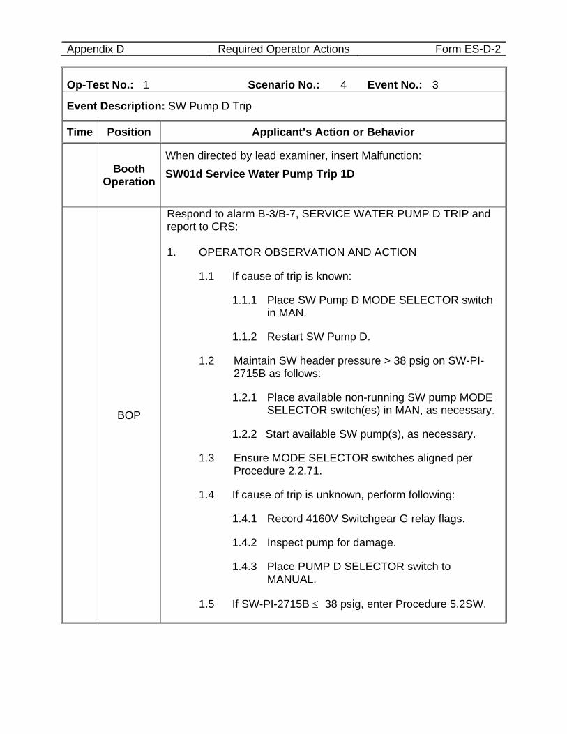
Appendix D Required Operator Actions Form ES-D-2
Op-Test No.: 1 Scenario No.: 4 Event No.: 3
Event Description: SW Pump D Trip
Time Position Applicant’s Action or Behavior
Booth Operation
When directed by lead examiner, insert Malfunction: SW01d Service Water Pump Trip 1D
BOP
Respond to alarm B-3/B-7, SERVICE WATER PUMP D TRIP and report to CRS: 1. OPERATOR OBSERVATION AND ACTION
1.1 If cause of trip is known:
1.1.1 Place SW Pump D MODE SELECTOR switch in MAN.
1.1.2 Restart SW Pump D.
1.2 Maintain SW header pressure > 38 psig on SW-PI-2715B as follows:
1.2.1 Place available non-running SW pump MODE SELECTOR switch(es) in MAN, as necessary.
1.2.2 Start available SW pump(s), as necessary.
1.3 Ensure MODE SELECTOR switches aligned per Procedure 2.2.71.
1.4 If cause of trip is unknown, perform following:
1.4.1 Record 4160V Switchgear G relay flags.
1.4.2 Inspect pump for damage.
1.4.3 Place PUMP D SELECTOR switch to MANUAL.
1.5 If SW-PI-2715B ≤ 38 psig, enter Procedure 5.2SW.
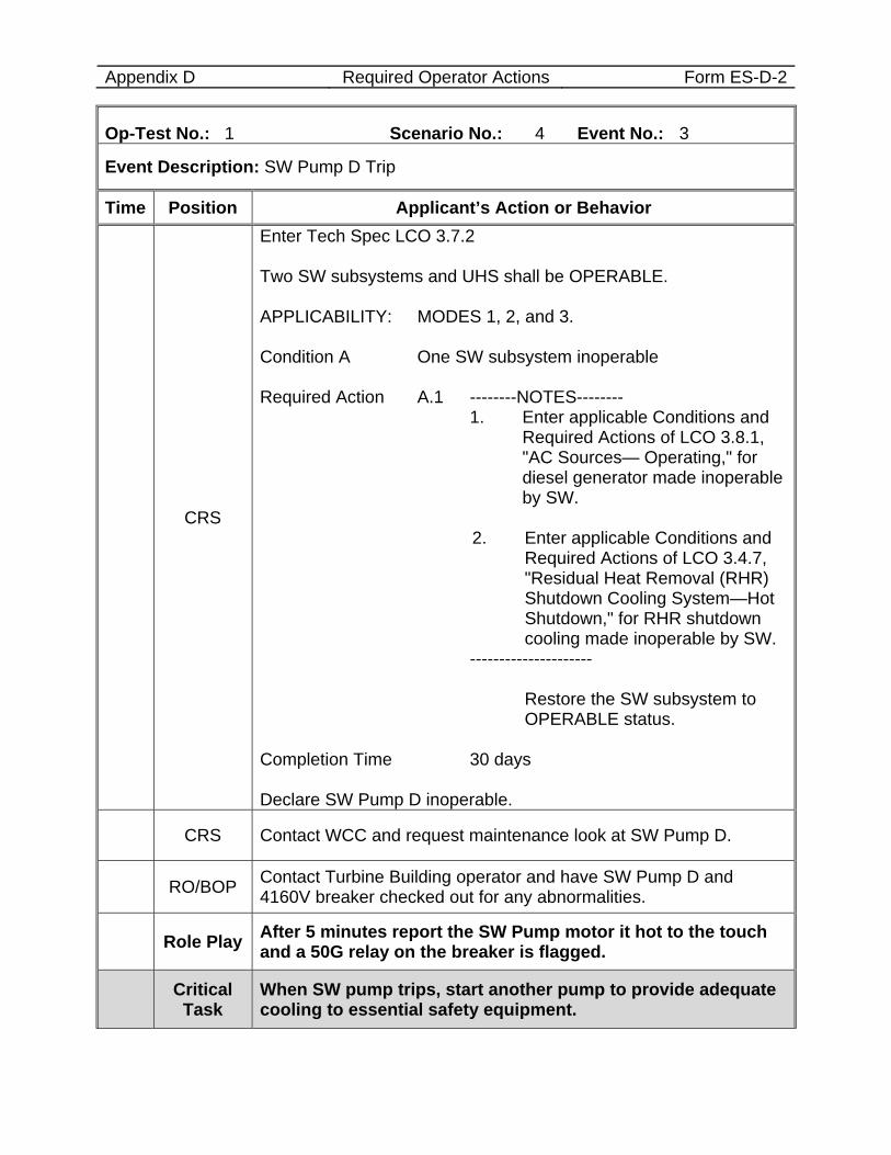
Appendix D Required Operator Actions Form ES-D-2
Op-Test No.: 1 Scenario No.: 4 Event No.: 3
Event Description: SW Pump D Trip
Time Position Applicant’s Action or Behavior
CRS
Enter Tech Spec LCO 3.7.2 Two SW subsystems and UHS shall be OPERABLE. APPLICABILITY: MODES 1, 2, and 3. Condition A One SW subsystem inoperable Required Action A.1 --------NOTES-------- 1. Enter applicable Conditions and
Required Actions of LCO 3.8.1, "AC Sources— Operating," for diesel generator made inoperable by SW.
2. Enter applicable Conditions and
Required Actions of LCO 3.4.7, "Residual Heat Removal (RHR) Shutdown Cooling System—Hot Shutdown," for RHR shutdown cooling made inoperable by SW.
--------------------- Restore the SW subsystem to
OPERABLE status. Completion Time 30 days Declare SW Pump D inoperable.
CRS Contact WCC and request maintenance look at SW Pump D.
RO/BOP Contact Turbine Building operator and have SW Pump D and 4160V breaker checked out for any abnormalities.
Role Play After 5 minutes report the SW Pump motor it hot to the touch and a 50G relay on the breaker is flagged.
Critical Task
When SW pump trips, start another pump to provide adequate cooling to essential safety equipment.
Appendix D Required Operator Actions Form ES-D-2
Op-Test No.: 1 Scenario No.: 4 Event No.: 3
Event Description: SW Pump D Trip
Time Position Applicant’s Action or Behavior
END OF EVENT
Notes
Proceed to the next event at direction of the lead examiner.
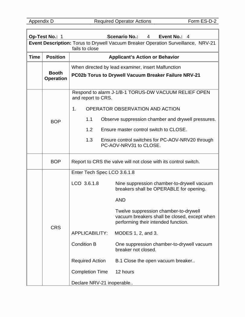
Appendix D Required Operator Actions Form ES-D-2
Op-Test No.: 1 Scenario No.: 4 Event No.: 4 Event Description: Torus to Drywell Vacuum Breaker Operation Surveillance, NRV-21
fails to close
Time Position Applicant’s Action or Behavior
Booth Operation
When directed by lead examiner, insert Malfunction PC02b Torus to Drywell Vacuum Breaker Failure NRV-21
BOP
Respond to alarm J-1/B-1 TORUS-DW VACUUM RELIEF OPEN and report to CRS. 1. OPERATOR OBSERVATION AND ACTION
1.1 Observe suppression chamber and drywell pressures.
1.2 Ensure master control switch to CLOSE.
1.3 Ensure control switches for PC-AOV-NRV20 through PC-AOV-NRV31 to CLOSE.
BOP Report to CRS the valve will not close with its control switch.
CRS
Enter Tech Spec LCO 3.6.1.8 LCO 3.6.1.8 Nine suppression chamber-to-drywell vacuum
breakers shall be OPERABLE for opening. AND
Twelve suppression chamber-to-drywell vacuum breakers shall be closed, except when performing their intended function.
APPLICABILITY: MODES 1, 2, and 3. Condition B One suppression chamber-to-drywell vacuum
breaker not closed. Required Action B.1 Close the open vacuum breaker.. Completion Time 12 hours Declare NRV-21 inoperable..
Appendix D Required Operator Actions Form ES-D-2
Op-Test No.: 1 Scenario No.: 4 Event No.: 4 Event Description: Torus to Drywell Vacuum Breaker Operation Surveillance, NRV-21
fails to close
Time Position Applicant’s Action or Behavior
END OF EVENT
Notes
Proceed to the next event at direction of the lead examiner.
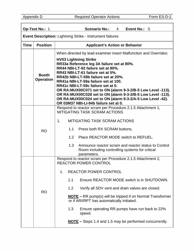
Appendix D Required Operator Actions Form ES-D-2
Op-Test No.: 1 Scenario No.: 4 Event No.: 5
Event Description: Lightning Strike - Instrument failures
Time Position Applicant’s Action or Behavior
Booth Operation
When directed by lead examiner insert Malfunction and Overrides: HV03 Lightning Strike RR33a Reference leg 3A failure set at 80%. RR44 NBI-LT-92 failure set at 80%. RR43 NBI-LT-61 failure set at 5%. RR42b NBI-LT-59b failure set at 20%. RR41a NBI-LT-59a failure set at 100. RR41c NBI-LT-59c failure set at 0. OR RA:MUX00C071 set to ON (alarm 9-3-2/B-5 Low Level -113). OR RA:MUX00C028 set to ON (alarm 9-3-2/B-5 Low Level -113). OR RA:MUX00C024 set to ON (alarm 9-3-2/A-5 Low Level -42). OR 03M37 NBI-LI-94b failure set at 0.
RO
Respond to reactor scram per Procedure 2.1.5 Attachment 1, MITIGATING TASK SCRAM ACTIONS 1. MITIGATING TASK SCRAM ACTIONS
1.1 Press both RX SCRAM buttons.
1.2 Place REACTOR MODE switch to REFUEL.
1.3 Announce reactor scram and reactor status to Control Room including controlling systems for critical parameters.
RO
Respond to reactor scram per Procedure 2.1.5 Attachment 2, REACTOR POWER CONTROL
1. REACTOR POWER CONTROL
1.1 Ensure REACTOR MODE switch is in SHUTDOWN.
1.2 Verify all SDV vent and drain valves are closed.
NOTE – RR pump(s) will be tripped if on Normal Transformer or if ARI/RPT has automatically initiated.
1.3 Ensure operating RR pumps have run back to 22% speed.
NOTE – Steps 1.4 and 1.5 may be performed concurrently.
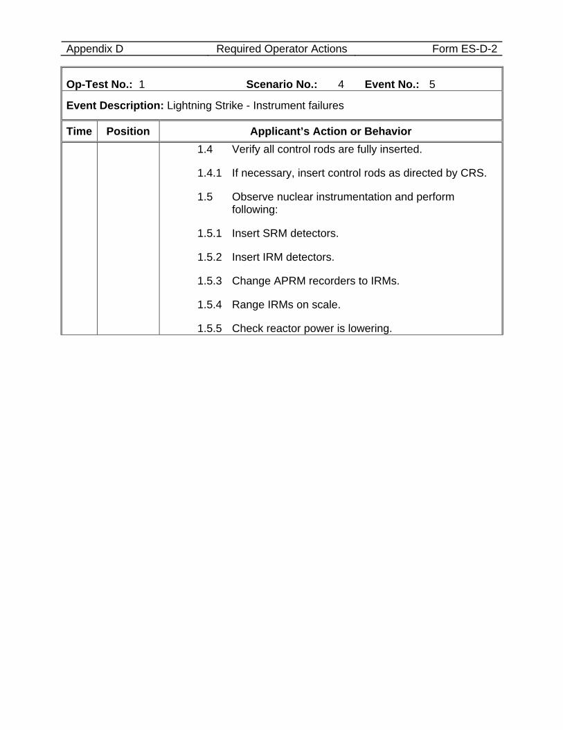
Appendix D Required Operator Actions Form ES-D-2
Op-Test No.: 1 Scenario No.: 4 Event No.: 5
Event Description: Lightning Strike - Instrument failures
Time Position Applicant’s Action or Behavior 1.4 Verify all control rods are fully inserted.
1.4.1 If necessary, insert control rods as directed by CRS.
1.5 Observe nuclear instrumentation and perform following:
1.5.1 Insert SRM detectors.
1.5.2 Insert IRM detectors.
1.5.3 Change APRM recorders to IRMs.
1.5.4 Range IRMs on scale.
1.5.5 Check reactor power is lowering.
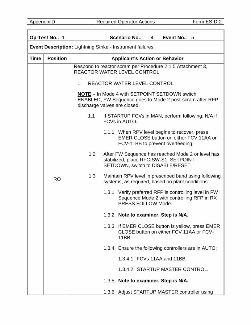
Appendix D Required Operator Actions Form ES-D-2
Op-Test No.: 1 Scenario No.: 4 Event No.: 5
Event Description: Lightning Strike - Instrument failures
Time Position Applicant’s Action or Behavior
RO
Respond to reactor scram per Procedure 2.1.5 Attachment 3, REACTOR WATER LEVEL CONTROL
1. REACTOR WATER LEVEL CONTROL
NOTE – In Mode 4 with SETPOINT SETDOWN switch ENABLED, FW Sequence goes to Mode 2 post-scram after RFP discharge valves are closed.
1.1 If STARTUP FCVs in MAN, perform following: N/A if FCVs in AUTO.
1.1.1 When RPV level begins to recover, press EMER CLOSE button on either FCV 11AA or FCV-11BB to prevent overfeeding.
1.2 After FW Sequence has reached Mode 2 or level has stabilized, place RFC-SW-S1, SETPOINT SETDOWN, switch to DISABLE/RESET.
1.3 Maintain RPV level in prescribed band using following systems, as required, based on plant conditions:
1.3.1 Verify preferred RFP is controlling level in FW Sequence Mode 2 with controlling RFP in RX PRESS FOLLOW Mode.
1.3.2 Note to examiner, Step is N/A. 1.3.3 If EMER CLOSE button is yellow, press EMER
CLOSE button on either FCV 11AA or FCV-11BB.
1.3.4 Ensure the following controllers are in AUTO:
1.3.4.1 FCVs 11AA and 11BB.
1.3.4.2 STARTUP MASTER CONTROL.
1.3.5 Note to examiner, Step is N/A. 1.3.6 Adjust STARTUP MASTER controller using
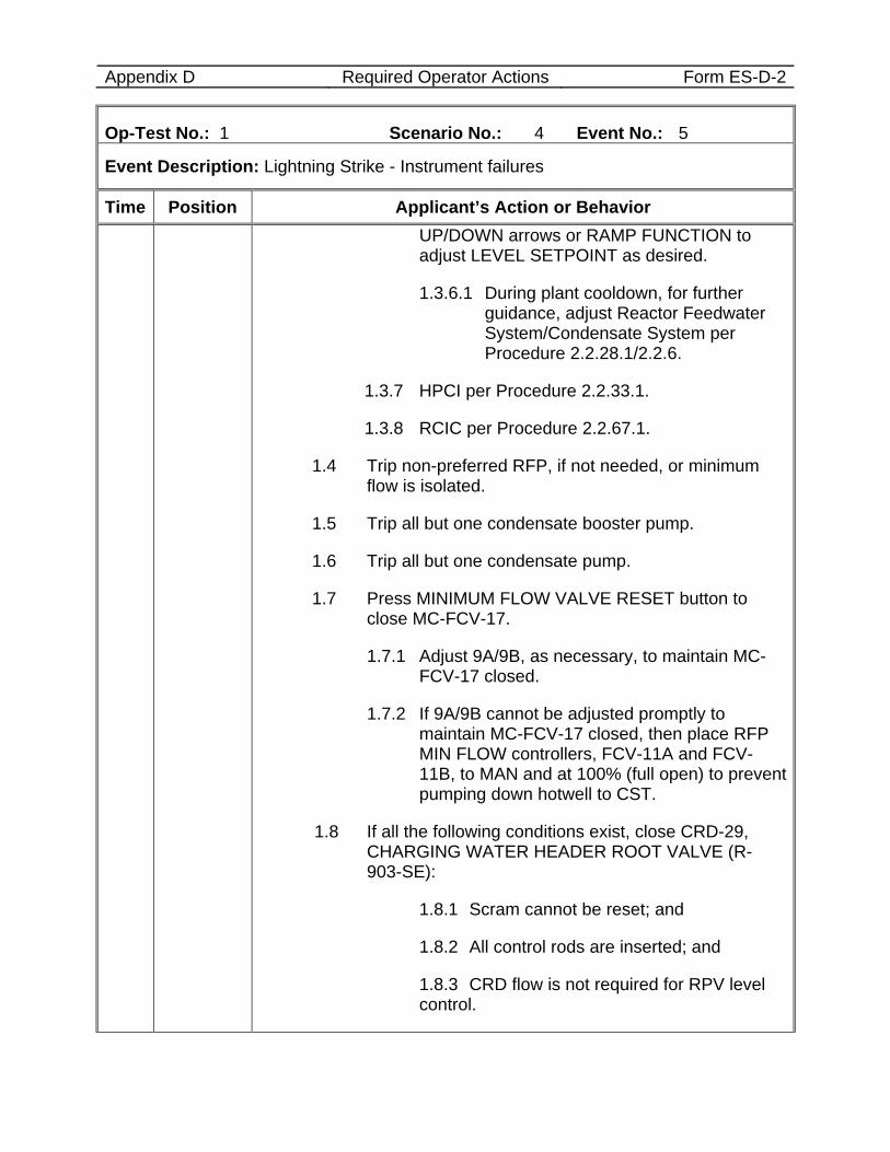
Appendix D Required Operator Actions Form ES-D-2
Op-Test No.: 1 Scenario No.: 4 Event No.: 5
Event Description: Lightning Strike - Instrument failures
Time Position Applicant’s Action or Behavior UP/DOWN arrows or RAMP FUNCTION to adjust LEVEL SETPOINT as desired.
1.3.6.1 During plant cooldown, for further guidance, adjust Reactor Feedwater System/Condensate System per Procedure 2.2.28.1/2.2.6.
1.3.7 HPCI per Procedure 2.2.33.1.
1.3.8 RCIC per Procedure 2.2.67.1.
1.4 Trip non-preferred RFP, if not needed, or minimum flow is isolated.
1.5 Trip all but one condensate booster pump.
1.6 Trip all but one condensate pump.
1.7 Press MINIMUM FLOW VALVE RESET button to close MC-FCV-17.
1.7.1 Adjust 9A/9B, as necessary, to maintain MC-FCV-17 closed.
1.7.2 If 9A/9B cannot be adjusted promptly to maintain MC-FCV-17 closed, then place RFP MIN FLOW controllers, FCV-11A and FCV-11B, to MAN and at 100% (full open) to prevent pumping down hotwell to CST.
1.8 If all the following conditions exist, close CRD-29, CHARGING WATER HEADER ROOT VALVE (R-903-SE):
1.8.1 Scram cannot be reset; and
1.8.2 All control rods are inserted; and
1.8.3 CRD flow is not required for RPV level control.
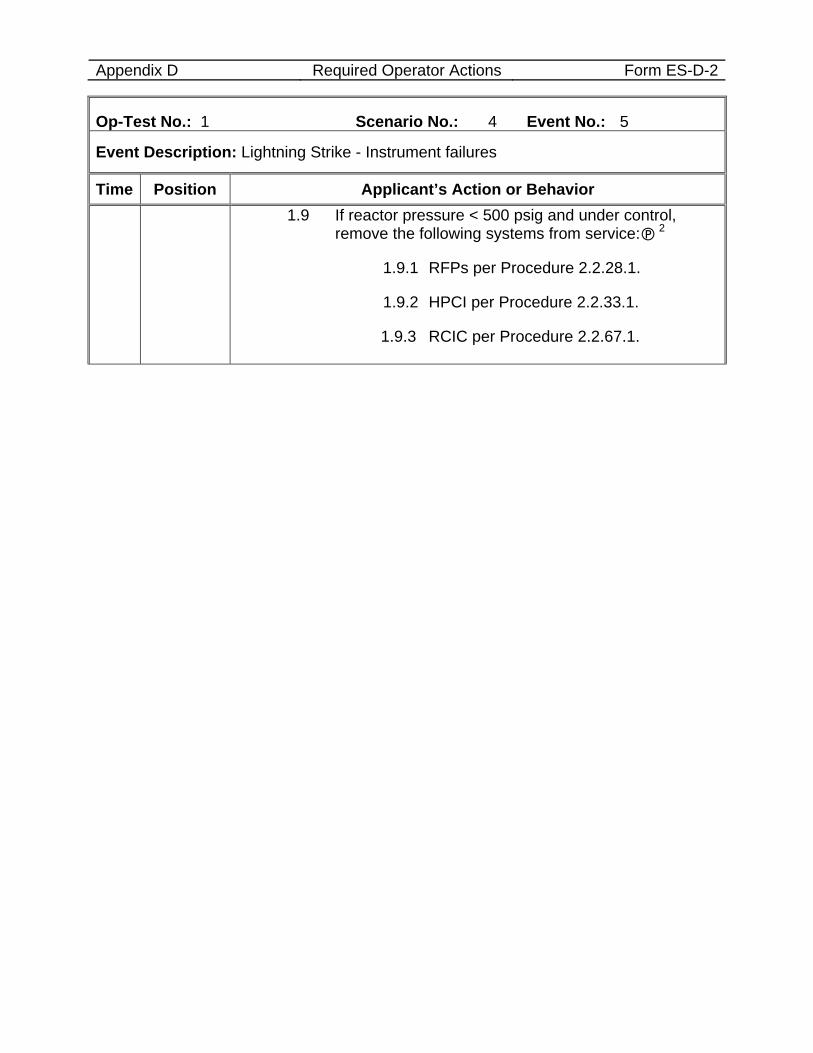
Appendix D Required Operator Actions Form ES-D-2
Op-Test No.: 1 Scenario No.: 4 Event No.: 5
Event Description: Lightning Strike - Instrument failures
Time Position Applicant’s Action or Behavior 1.9 If reactor pressure < 500 psig and under control,
remove the following systems from service: 2
1.9.1 RFPs per Procedure 2.2.28.1.
1.9.2 HPCI per Procedure 2.2.33.1.
1.9.3 RCIC per Procedure 2.2.67.1.
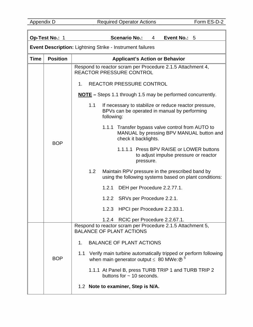
Appendix D Required Operator Actions Form ES-D-2
Op-Test No.: 1 Scenario No.: 4 Event No.: 5
Event Description: Lightning Strike - Instrument failures
Time Position Applicant’s Action or Behavior
BOP
Respond to reactor scram per Procedure 2.1.5 Attachment 4, REACTOR PRESSURE CONTROL
1. REACTOR PRESSURE CONTROL
NOTE – Steps 1.1 through 1.5 may be performed concurrently.
1.1 If necessary to stabilize or reduce reactor pressure, BPVs can be operated in manual by performing following:
1.1.1 Transfer bypass valve control from AUTO to MANUAL by pressing BPV MANUAL button and check it backlights.
1.1.1.1 Press BPV RAISE or LOWER buttons to adjust impulse pressure or reactor pressure.
1.2 Maintain RPV pressure in the prescribed band by using the following systems based on plant conditions:
1.2.1 DEH per Procedure 2.2.77.1.
1.2.2 SRVs per Procedure 2.2.1.
1.2.3 HPCI per Procedure 2.2.33.1.
1.2.4 RCIC per Procedure 2.2.67.1.
BOP
Respond to reactor scram per Procedure 2.1.5 Attachment 5, BALANCE OF PLANT ACTIONS
1. BALANCE OF PLANT ACTIONS
1.1 Verify main turbine automatically tripped or perform following when main generator output ≤ 80 MWe: 5
1.1.1 At Panel B, press TURB TRIP 1 and TURB TRIP 2 buttons for ~ 10 seconds.
1.2 Note to examiner, Step is N/A.
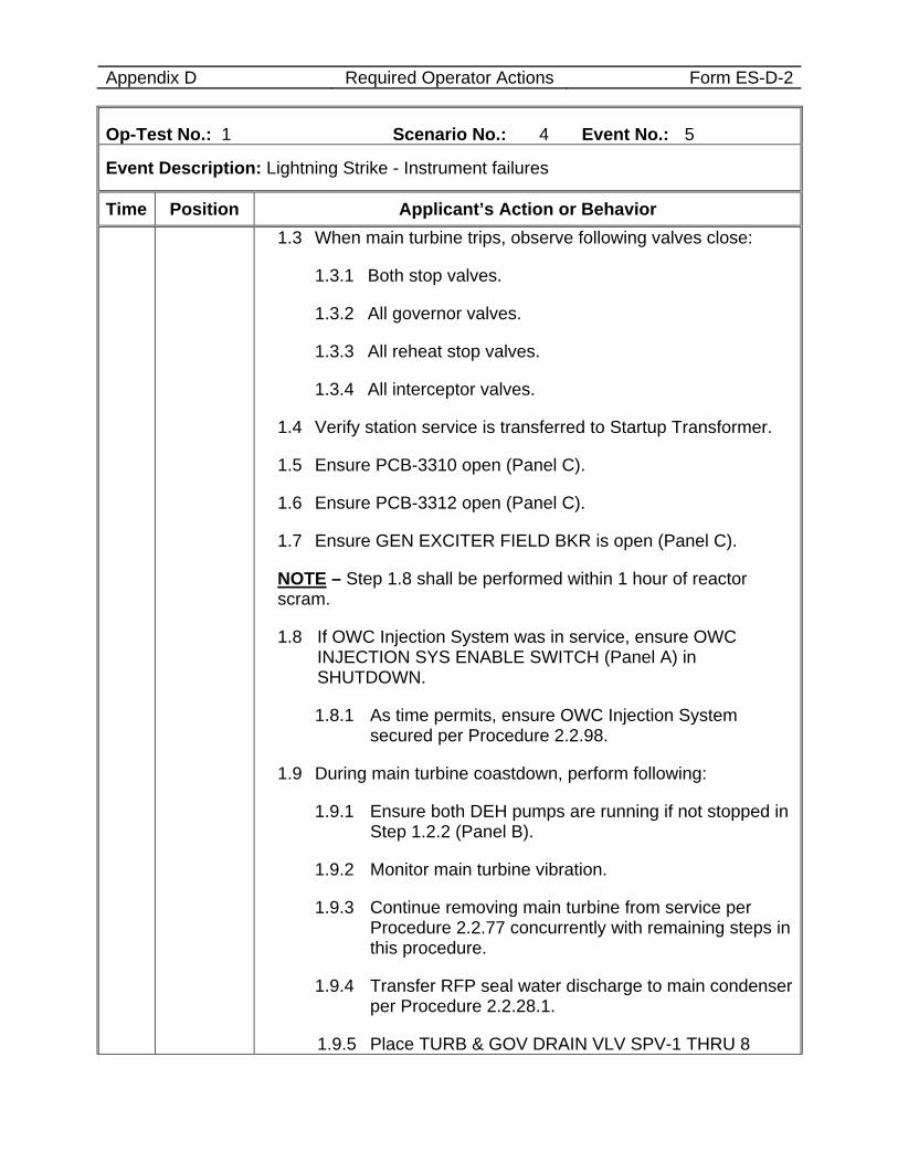
Appendix D Required Operator Actions Form ES-D-2
Op-Test No.: 1 Scenario No.: 4 Event No.: 5
Event Description: Lightning Strike - Instrument failures
Time Position Applicant’s Action or Behavior 1.3 When main turbine trips, observe following valves close:
1.3.1 Both stop valves.
1.3.2 All governor valves.
1.3.3 All reheat stop valves.
1.3.4 All interceptor valves.
1.4 Verify station service is transferred to Startup Transformer.
1.5 Ensure PCB-3310 open (Panel C).
1.6 Ensure PCB-3312 open (Panel C).
1.7 Ensure GEN EXCITER FIELD BKR is open (Panel C).
NOTE – Step 1.8 shall be performed within 1 hour of reactor scram.
1.8 If OWC Injection System was in service, ensure OWC INJECTION SYS ENABLE SWITCH (Panel A) in SHUTDOWN.
1.8.1 As time permits, ensure OWC Injection System secured per Procedure 2.2.98.
1.9 During main turbine coastdown, perform following:
1.9.1 Ensure both DEH pumps are running if not stopped in Step 1.2.2 (Panel B).
1.9.2 Monitor main turbine vibration.
1.9.3 Continue removing main turbine from service per Procedure 2.2.77 concurrently with remaining steps in this procedure.
1.9.4 Transfer RFP seal water discharge to main condenser per Procedure 2.2.28.1.
1.9.5 Place TURB & GOV DRAIN VLV SPV-1 THRU 8
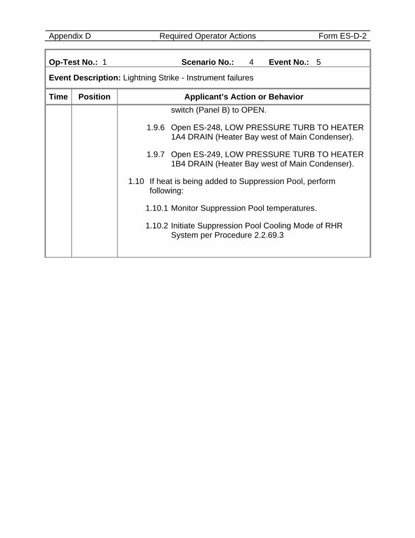
Appendix D Required Operator Actions Form ES-D-2
Op-Test No.: 1 Scenario No.: 4 Event No.: 5
Event Description: Lightning Strike - Instrument failures
Time Position Applicant’s Action or Behavior switch (Panel B) to OPEN.
1.9.6 Open ES-248, LOW PRESSURE TURB TO HEATER 1A4 DRAIN (Heater Bay west of Main Condenser).
1.9.7 Open ES-249, LOW PRESSURE TURB TO HEATER 1B4 DRAIN (Heater Bay west of Main Condenser).
1.10 If heat is being added to Suppression Pool, perform following:
1.10.1 Monitor Suppression Pool temperatures.
1.10.2 Initiate Suppression Pool Cooling Mode of RHR System per Procedure 2.2.69.3
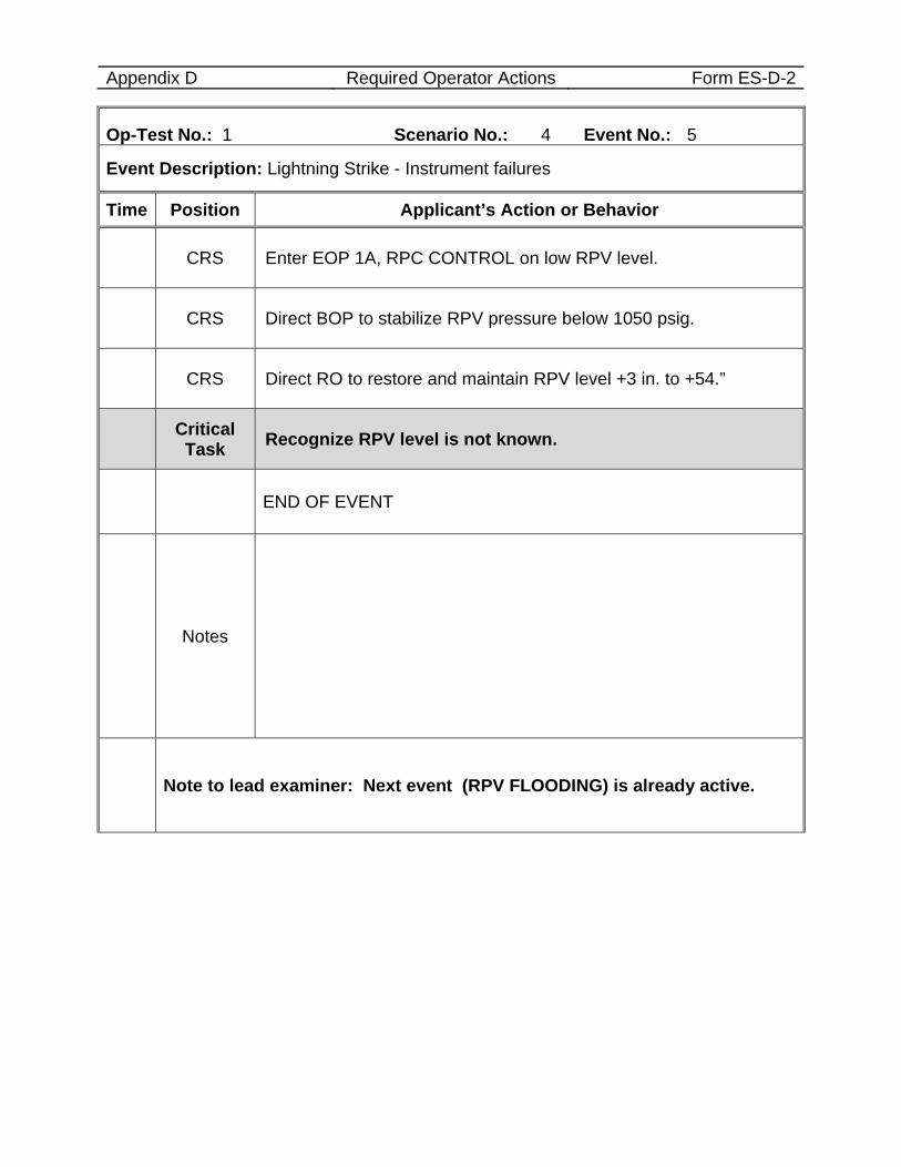
Appendix D Required Operator Actions Form ES-D-2
Op-Test No.: 1 Scenario No.: 4 Event No.: 5
Event Description: Lightning Strike - Instrument failures
Time Position Applicant’s Action or Behavior
CRS Enter EOP 1A, RPC CONTROL on low RPV level.
CRS Direct BOP to stabilize RPV pressure below 1050 psig.
CRS Direct RO to restore and maintain RPV level +3 in. to +54.”
Critical Task Recognize RPV level is not known.
END OF EVENT
Notes
Note to lead examiner: Next event (RPV FLOODING) is already active.
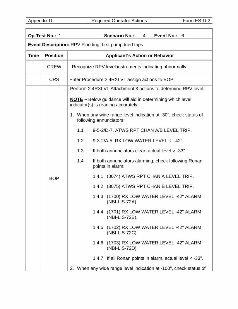
Appendix D Required Operator Actions Form ES-D-2
Op-Test No.: 1 Scenario No.: 4 Event No.: 6
Event Description: RPV Flooding, first pump tried trips
Time Position Applicant’s Action or Behavior
CREW Recognize RPV level instruments indicating abnormally.
CRS Enter Procedure 2.4RXLVL assign actions to BOP.
BOP
Perform 2.4RXLVL Attachment 3 actions to determine RPV level: NOTE – Below guidance will aid in determining which level indicator(s) is reading accurately.
1. When any wide range level indication at -30", check status of following annunciators:
1.1 9-5-2/D-7, ATWS RPT CHAN A/B LEVEL TRIP.
1.2 9-3-2/A-5, RX LOW WATER LEVEL ≤ -42".
1.3 If both annunciators clear, actual level > -33".
1.4 If both annunciators alarming, check following Ronan points in alarm:
1.4.1 (3074) ATWS RPT CHAN A LEVEL TRIP.
1.4.2 (3075) ATWS RPT CHAN B LEVEL TRIP.
1.4.3 (1700) RX LOW WATER LEVEL -42" ALARM (NBI-LIS-72A).
1.4.4 (1701) RX LOW WATER LEVEL -42" ALARM (NBI-LIS-72B).
1.4.5 (1702) RX LOW WATER LEVEL -42" ALARM (NBI-LIS-72C).
1.4.6 (1703) RX LOW WATER LEVEL -42" ALARM (NBI-LIS-72D).
1.4.7 If all Ronan points in alarm, actual level < -33".
2. When any wide range level indication at -100", check status of
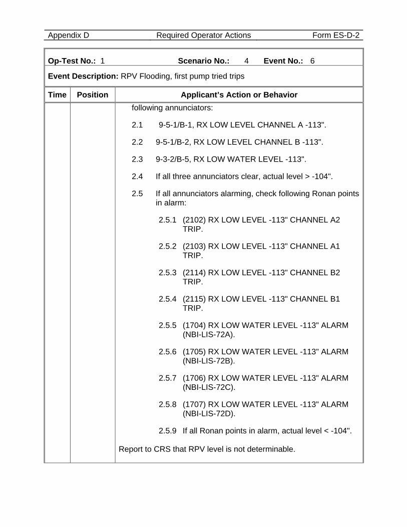
Appendix D Required Operator Actions Form ES-D-2
Op-Test No.: 1 Scenario No.: 4 Event No.: 6
Event Description: RPV Flooding, first pump tried trips
Time Position Applicant’s Action or Behavior following annunciators:
2.1 9-5-1/B-1, RX LOW LEVEL CHANNEL A -113".
2.2 9-5-1/B-2, RX LOW LEVEL CHANNEL B -113".
2.3 9-3-2/B-5, RX LOW WATER LEVEL -113".
2.4 If all three annunciators clear, actual level > -104".
2.5 If all annunciators alarming, check following Ronan points in alarm:
2.5.1 (2102) RX LOW LEVEL -113" CHANNEL A2 TRIP.
2.5.2 (2103) RX LOW LEVEL -113" CHANNEL A1 TRIP.
2.5.3 (2114) RX LOW LEVEL -113" CHANNEL B2 TRIP.
2.5.4 (2115) RX LOW LEVEL -113" CHANNEL B1 TRIP.
2.5.5 (1704) RX LOW WATER LEVEL -113" ALARM (NBI-LIS-72A).
2.5.6 (1705) RX LOW WATER LEVEL -113" ALARM (NBI-LIS-72B).
2.5.7 (1706) RX LOW WATER LEVEL -113" ALARM (NBI-LIS-72C).
2.5.8 (1707) RX LOW WATER LEVEL -113" ALARM (NBI-LIS-72D).
2.5.9 If all Ronan points in alarm, actual level < -104".
Report to CRS that RPV level is not determinable.
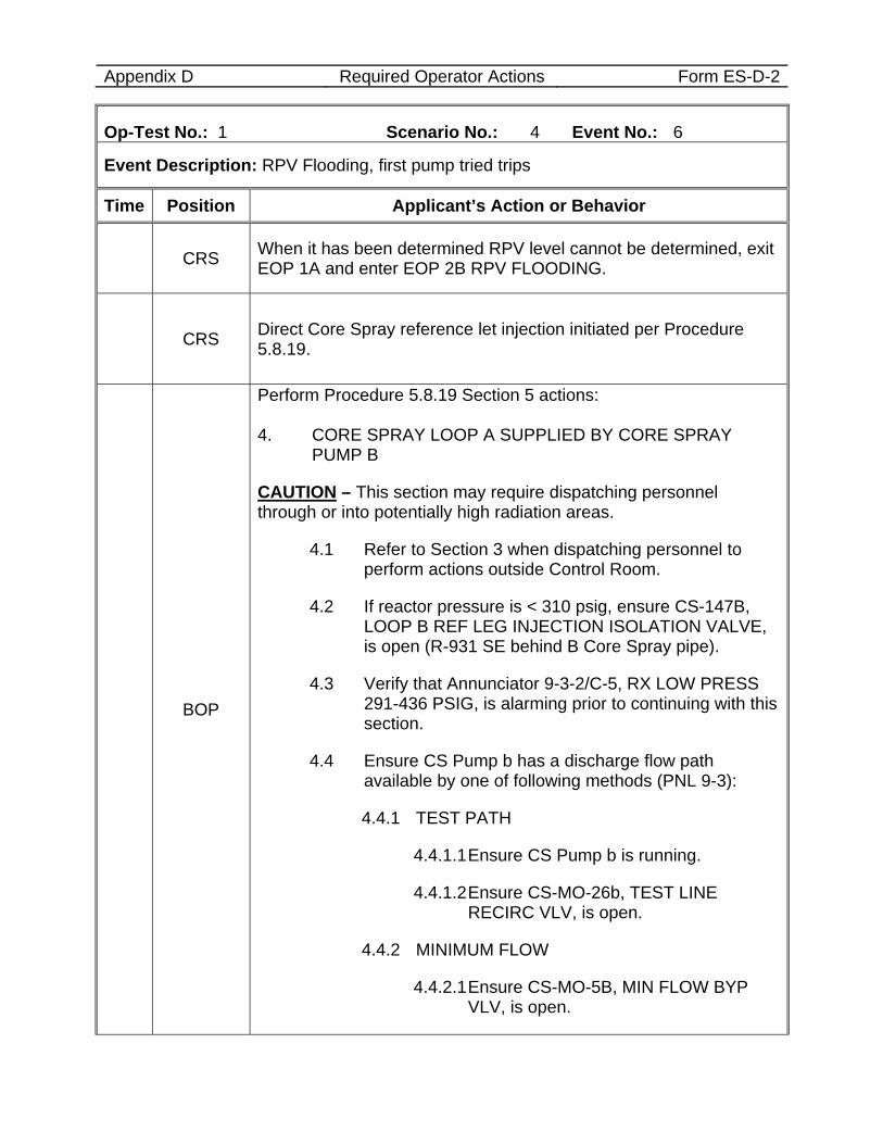
Appendix D Required Operator Actions Form ES-D-2
Op-Test No.: 1 Scenario No.: 4 Event No.: 6
Event Description: RPV Flooding, first pump tried trips
Time Position Applicant’s Action or Behavior
CRS When it has been determined RPV level cannot be determined, exit EOP 1A and enter EOP 2B RPV FLOODING.
CRS Direct Core Spray reference let injection initiated per Procedure 5.8.19.
BOP
Perform Procedure 5.8.19 Section 5 actions: 4. CORE SPRAY LOOP A SUPPLIED BY CORE SPRAY
PUMP B
CAUTION – This section may require dispatching personnel through or into potentially high radiation areas.
4.1 Refer to Section 3 when dispatching personnel to perform actions outside Control Room.
4.2 If reactor pressure is < 310 psig, ensure CS-147B, LOOP B REF LEG INJECTION ISOLATION VALVE, is open (R-931 SE behind B Core Spray pipe).
4.3 Verify that Annunciator 9-3-2/C-5, RX LOW PRESS 291-436 PSIG, is alarming prior to continuing with this section.
4.4 Ensure CS Pump b has a discharge flow path available by one of following methods (PNL 9-3):
4.4.1 TEST PATH
4.4.1.1 Ensure CS Pump b is running.
4.4.1.2 Ensure CS-MO-26b, TEST LINE RECIRC VLV, is open.
4.4.2 MINIMUM FLOW
4.4.2.1 Ensure CS-MO-5B, MIN FLOW BYP VLV, is open.
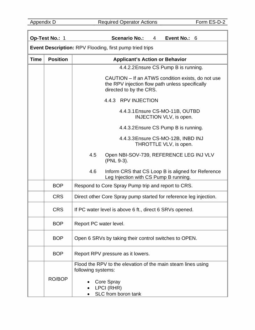
Appendix D Required Operator Actions Form ES-D-2
Op-Test No.: 1 Scenario No.: 4 Event No.: 6
Event Description: RPV Flooding, first pump tried trips
Time Position Applicant’s Action or Behavior 4.4.2.2 Ensure CS Pump B is running.
CAUTION – If an ATWS condition exists, do not use the RPV injection flow path unless specifically directed to by the CRS.
4.4.3 RPV INJECTION
4.4.3.1 Ensure CS-MO-11B, OUTBD INJECTION VLV, is open.
4.4.3.2 Ensure CS Pump B is running.
4.4.3.3 Ensure CS-MO-12B, INBD INJ THROTTLE VLV, is open.
4.5 Open NBI-SOV-739, REFERENCE LEG INJ VLV (PNL 9-3).
4.6 Inform CRS that CS Loop B is aligned for Reference Leg Injection with CS Pump B running.
BOP Respond to Core Spray Pump trip and report to CRS.
CRS Direct other Core Spray pump started for reference leg injection.
CRS If PC water level is above 6 ft., direct 6 SRVs opened.
BOP Report PC water level.
BOP Open 6 SRVs by taking their control switches to OPEN.
BOP Report RPV pressure as it lowers.
RO/BOP
Flood the RPV to the elevation of the main steam lines using following systems:
• Core Spray • LPCI (RHR) • SLC from boron tank
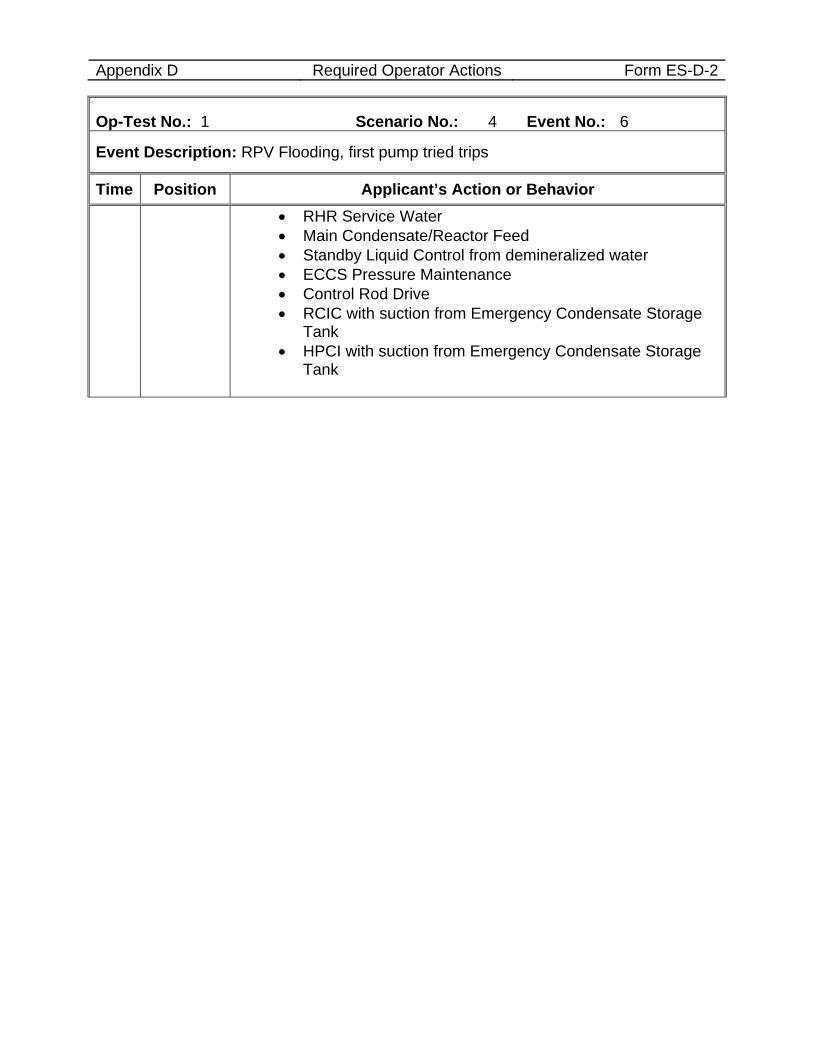
Appendix D Required Operator Actions Form ES-D-2
Op-Test No.: 1 Scenario No.: 4 Event No.: 6
Event Description: RPV Flooding, first pump tried trips
Time Position Applicant’s Action or Behavior • RHR Service Water • Main Condensate/Reactor Feed • Standby Liquid Control from demineralized water • ECCS Pressure Maintenance • Control Rod Drive • RCIC with suction from Emergency Condensate Storage
Tank • HPCI with suction from Emergency Condensate Storage
Tank
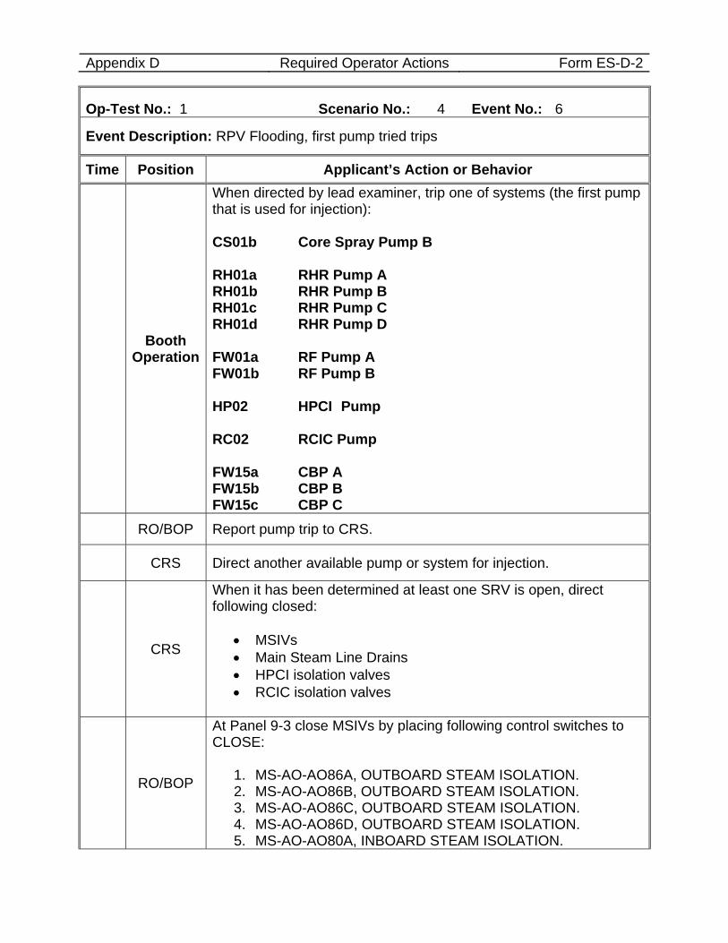
Appendix D Required Operator Actions Form ES-D-2
Op-Test No.: 1 Scenario No.: 4 Event No.: 6
Event Description: RPV Flooding, first pump tried trips
Time Position Applicant’s Action or Behavior
Booth Operation
When directed by lead examiner, trip one of systems (the first pump that is used for injection): CS01b Core Spray Pump B RH01a RHR Pump A RH01b RHR Pump B RH01c RHR Pump C RH01d RHR Pump D FW01a RF Pump A FW01b RF Pump B HP02 HPCI Pump RC02 RCIC Pump FW15a CBP A FW15b CBP B FW15c CBP C
RO/BOP Report pump trip to CRS.
CRS Direct another available pump or system for injection.
CRS
When it has been determined at least one SRV is open, direct following closed:
• MSIVs • Main Steam Line Drains • HPCI isolation valves • RCIC isolation valves
RO/BOP
At Panel 9-3 close MSIVs by placing following control switches to CLOSE:
1. MS-AO-AO86A, OUTBOARD STEAM ISOLATION. 2. MS-AO-AO86B, OUTBOARD STEAM ISOLATION. 3. MS-AO-AO86C, OUTBOARD STEAM ISOLATION. 4. MS-AO-AO86D, OUTBOARD STEAM ISOLATION. 5. MS-AO-AO80A, INBOARD STEAM ISOLATION.
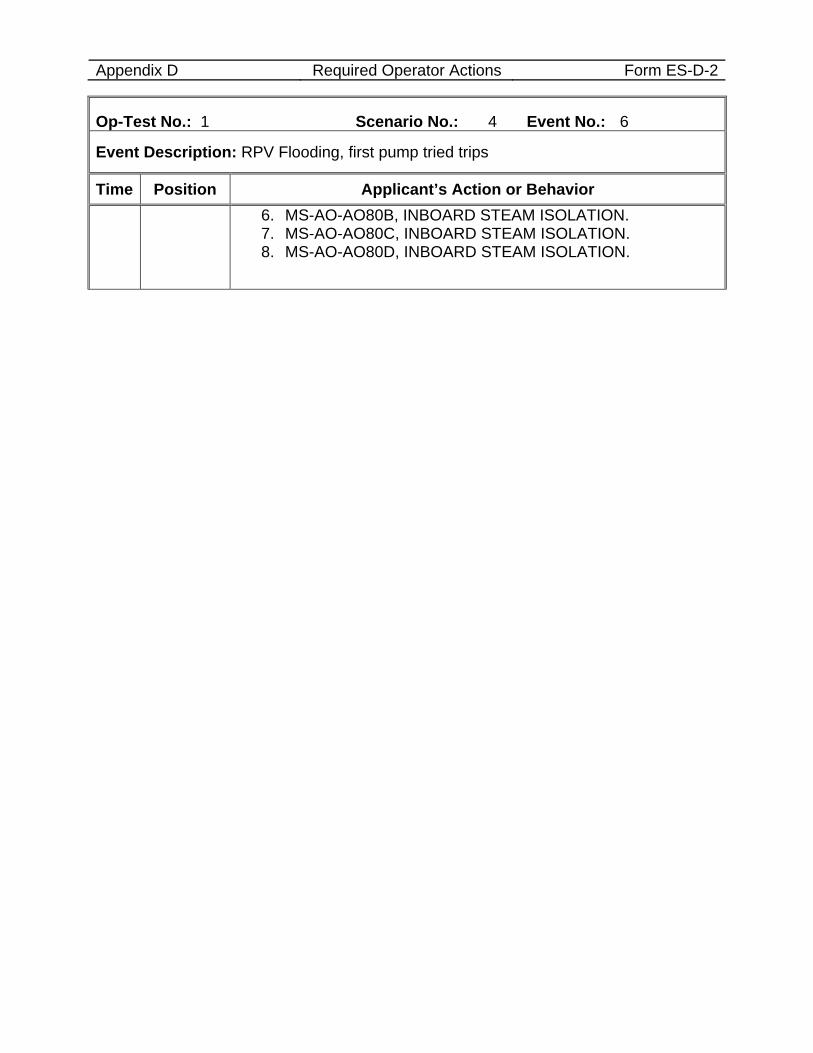
Appendix D Required Operator Actions Form ES-D-2
Op-Test No.: 1 Scenario No.: 4 Event No.: 6
Event Description: RPV Flooding, first pump tried trips
Time Position Applicant’s Action or Behavior 6. MS-AO-AO80B, INBOARD STEAM ISOLATION. 7. MS-AO-AO80C, INBOARD STEAM ISOLATION. 8. MS-AO-AO80D, INBOARD STEAM ISOLATION.
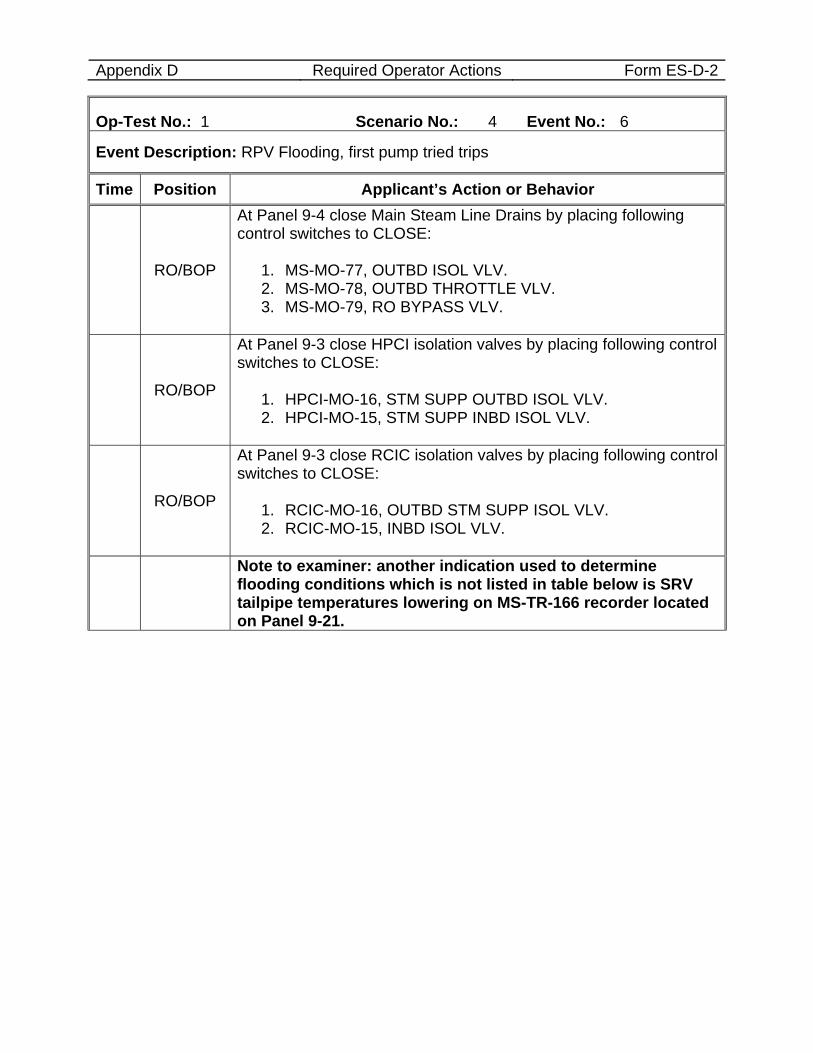
Appendix D Required Operator Actions Form ES-D-2
Op-Test No.: 1 Scenario No.: 4 Event No.: 6
Event Description: RPV Flooding, first pump tried trips
Time Position Applicant’s Action or Behavior
RO/BOP
At Panel 9-4 close Main Steam Line Drains by placing following control switches to CLOSE:
1. MS-MO-77, OUTBD ISOL VLV. 2. MS-MO-78, OUTBD THROTTLE VLV. 3. MS-MO-79, RO BYPASS VLV.
RO/BOP
At Panel 9-3 close HPCI isolation valves by placing following control switches to CLOSE:
1. HPCI-MO-16, STM SUPP OUTBD ISOL VLV. 2. HPCI-MO-15, STM SUPP INBD ISOL VLV.
RO/BOP
At Panel 9-3 close RCIC isolation valves by placing following control switches to CLOSE:
1. RCIC-MO-16, OUTBD STM SUPP ISOL VLV. 2. RCIC-MO-15, INBD ISOL VLV.
Note to examiner: another indication used to determine flooding conditions which is not listed in table below is SRV tailpipe temperatures lowering on MS-TR-166 recorder located on Panel 9-21.
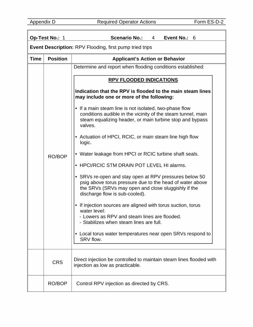
Appendix D Required Operator Actions Form ES-D-2
Op-Test No.: 1 Scenario No.: 4 Event No.: 6
Event Description: RPV Flooding, first pump tried trips
Time Position Applicant’s Action or Behavior
RO/BOP
Determine and report when flooding conditions established:
RPV FLOODED INDICATIONS Indication that the RPV is flooded to the main steam lines may include one or more of the following: • If a main steam line is not isolated, two-phase flow
conditions audible in the vicinity of the steam tunnel, main steam equalizing header, or main turbine stop and bypass valves.
• Actuation of HPCI, RCIC, or main steam line high flow
logic. • Water leakage from HPCI or RCIC turbine shaft seals. • HPCI/RCIC STM DRAIN POT LEVEL HI alarms. • SRVs re-open and stay open at RPV pressures below 50
psig above torus pressure due to the head of water above the SRVs (SRVs may open and close sluggishly if the discharge flow is sub-cooled).
• If injection sources are aligned with torus suction, torus
water level: - Lowers as RPV and steam lines are flooded. - Stabilizes when steam lines are full. • Local torus water temperatures near open SRVs respond to
SRV flow.
CRS Direct injection be controlled to maintain steam lines flooded with injection as low as practicable.
RO/BOP Control RPV injection as directed by CRS.
Appendix D Required Operator Actions Form ES-D-2
Op-Test No.: 1 Scenario No.: 4 Event No.: 6
Event Description: RPV Flooding, first pump tried trips
Time Position Applicant’s Action or Behavior
Critical Task
When RPV level not determinable, flood the RPV to the elevation of the main steam lines to ensure core cooling by submergence.
END OF EVENT
Notes
When RPV FLOODING conditions are established and the lead examiner has observed enough of the scenario, then terminate the scenario.