Embed Size (px)
Citation preview
RECEIVED
MAY 2 2 1935OFFICE OF THE DIRECTOR
WSTM DIVISION
DOCUMENT SAP-1
REVISED __SAMPLING AND ANALYSIS PLAN
DUAL VACUUM EXTRACTION REMEDIATIONRALSTON DISPOSAL SITE - CEDAR RAPIDS, IOWA
TERRA VAC PROJECT #62-0007
T€RRfl VflC
Submitted to:Rockwell International
Cedar Rapids, Iowa
Prepared by:Terra Vac
Darien, Illinois
Issued:MAY 1995
on rs-:t,l'ic^ por
T€RRfl VflCTABLE OF CONTENTS
Ease
1.0 INTRODUCTION 1
2.0 PROJECT DESCRIPTION 2
2.1 Site History/Previous Work 22.2 Project Description 22.3 Project Work Tasks 2
2.3.1 Project Design and Preparations .32.3.2 DVE and Groundwater Well Installation 32.3.3 System Construction 32.3.4 System Startup Operation and Monitoring 42.3.5 Evaluation and Reporting 4
3.0 SYSTEM AND SAMPLING OBJECTIVES 5
3.1 System Optimization 5
4.0 SAMPLE TYPES, LOCATIONS AND FREQUENCY 6
4.1 Vapor Sampling and Analysis 84.2 Groundwater Sampling and Analysis 84.3 Air monitoring 8
5.0 SAMPLING EQUIPMENT AND PROCEDURES 9
5.1 Groundwater Samples - Headspace Analysis 95.2 Groundwater Samples - Liquid Sample Concentration 95.3 On-site Vapor Analysis 105.4 Process Monitoring 115.5 Field Decontamination 11
6.0 QUALITY ASSURANCE/QUALITY CONTROL SAMPLES 12
6.1 Calibration Procedures and Frequency 126.2 Calibration Standards 136.3 Blanks 136.4 Replicates/Duplicates 146.5 Spike Recovery 146.6 Field Equipment 14
7.0 SAMPLING HANDLING AND ANALYSIS 15
T6RRfl VflC1.0 INTRODUCTION
This Sampling and Analysis Plan (SAP) has been developed in conjunction with aQuality Assurance Project Plan (QAPP) and the Operations and Maintenance Manual(O&M) to provide field guidance for all environmental sampling to be conducted as partof the dual vacuum extraction (DVE) remediation system to be installed and operated atthe Ralston Disposal site in Cedar Rapids, Iowa.
The SAP consists of the following components:
1. A field sampling plan that provides guidance for all environmental mediasampling and process monitoring to be performed as part of the project.
2. A Quality Assurance Project Plan (QAPP) that describes the sampleanalysis procedures and the policy, organization, functional activities, andquality assurance/quality control protocols necessary to achieve theprescribed data quality objectives.
The SAP addresses all proposed sampling activities to be conducted during the DVEsystem operations, and may be amended at a future date as necessary to reflectmodifications to the work plan. Sampling methods detailed in this plan will be strictlyadhered to. Any deviations from or additions to this plan will be carefully documentedin the site logbook. All field-generated forms and labels will be entered into or attachedto the site logbook.
The Sampling and Analysis Plan is organized into six sections. Section 2.0 describesthe Ralston Disposal site and the planned activities throughout the project. Section 3.0provides the sampling and data quality objectives for the planned environmentalmonitoring activities. Sample selection criteria, sample types, locations and frequency,sample equipment and procedures, and sample handling are outlined in Sections 4.0through 6.0.
A Site-Specific Work Plan (Work Plan) has been submitted to address work methodsand defines terms used in this document. Health and Safety and training requirementsare included in the Health and Safety Plan (HASP). Quality issues are addressed in theQuality Assurance Project Plan (QAPP).
Rockwell SAPP / Ralston Disposal Site - Cedar Rapids, Iowa Terra Vac #62-0007 Page 1 of 15
©,'
TCRRfl VflC2.0 PROJECT DESCRIPTION
2J. Site History/Previous WorkThe Ralston site is located in Linn County, Cedar Rapids, Iowa. The site Vv'aspreviously used as a disposal area for wastes from industrial sources, including a goldplating operation, from 1956 to 1958. In addition, the site was used by local businessesand residents for waste disposal purposes. Wastes identified at the site includesolvents, paint sludge, and general industrial refuse.
Information listing hazardous substances disposed at the site was submitted byRockwell to the United States Environmental Protection Agency (USEPA) in 1981. Apreliminary investigation conducted in 1985 indicated that soil and groundwatercontamination may have resulted from previous disposal activities at the site. Furtherinvestigations conducted in 1988 resulted in the removal of two drums ofconcrete-encapsulated cyanide.
Based on these initial investigations and additional sampling conducted by Rockwell in1991. a Remedial Investigation/Feasibility Study (RI/FS) Order was entered into byRockwell with the USEPA. Montgomery Watson (Montgomery) began the RI/FS in1992. and a Removal Action Work Plan was approved in May of 1994.
2.2 Project Description
Terra Vac has been contracted by Rockwell to design, install, and startup a DVEsystem to address the source of VOC contamination contained in the unsaturated soilsand alluvial groundwater system at the Ralston site. DVE is the simultaneousextraction of both soil vapor and groundwater from a single well. This technologycauses a drawdown of the water levels in the area of the DVE well, creating additionalunsaturated soils which are then remediated by the vacuum extraction process. Thedesign includes 13 DVE wells, 3 groundwater extraction wells, a vacuum extractionpump capable of approximately 1,000 scfm at 12 inches of mercury vacuum for theextraction of subsurface vapors, a 2,000 scfm catalytic oxidation and scrubber systemto treat the extracted vapors and the off-gas from a groundwater treatment systemconsisting of two, 30-foot packed towers with a 10 HP blower capable of 1,000 scfm.
2.3 Project Work Tasks
The DVE remediation project at the Ralston Disposal site will require theimplementation of several tasks. These tasks include:
* Project design and preparations* DVE and groundwater well installation» System installation and construction
Rockwell SAPP / Ralston Disposal Site - Cedar Rapids, Iowa Terra Vac #62-0007 Page 1 of 15

TERRfl VRC2.3.4 System Startup Operation and Monitoring
Once constructed, the system will be operated and optimized. This startup period isexpected to last approximately four weeks. Throughout the testing period, the site willbe staffed by Terra Vac personnel experienced in VE operations. It is anticipated that,at a minimum, the site will be staffed by a Project Chemist and a RemediationTechnician. The chemist will operate a mobile gas chromatograph (GC), calibrated toquantify each of the target VOCs. This will provide real time data upon which operatingdecisions can be made. Data collected during the continued operations will include, butis not limited to, the following parameters:
» extracted air flows and vacuums* extracted vapor and groundwater concentrations* subsurface vacuums and flows* groundwater recovery and drawdown rates* treatment systems efficiency* optimal mode of operations
2.3.5 Evaluation and Reporting
Terra Vac and/or Rockwell will collect and evaluate all data to determine the following:
* zones of influence and subsurface flow patterns* system extraction rates* VOC mass recovered» groundwater recovery rates* estimated timeframe for remediation
A report will document the field activities and evaluate the data collected during theDVE system startup period. Additional reporting is anticipated to be completed on aquarterly basis.
Rockwell SAPP / Ralston Disposal Site - Cedar Rapids, Iowa Terra Vac #62-0007 Page 4 of 15
"on recy ",/
T€RRfl VflC3.0 SYSTEM AND SAMPLING OBJECTIVES
The overall goal of the DVE system is to remove the source of groundwatercontamination contained in the unsaturated soils and the alluvial groundwater system atthe site. All samples and process monitoring data will be collected and analyzed in amanner that facilitates achieving the primary and secondary objectives. Specificobjectives as they relate to sample collection and analysis include:
Primary Objectives
Design, install, and startup a DVE system to remediate unsaturated soilcontamination at the Ralston Disposal site.
Determine optimal DVE system operating parameters throughout theoperation the system.
Secondary Objectives
To determine the characteristics associated with the subsurface inthe remedial area, including zone of vacuum influence information andgroundwater drawdown rates.
To monitor the extracted VOC concentrations and airflow during operations to quantify the mass extracted and the change in concentrationsover time.
To quantify the efficiency of the contaminant removal system and ensurecompliance with all regulatory discharge criteria.
3.1 System Optimization
Determination of the optimal operating manner of the system will be a function of theresults obtained during monitoring of the system. Sampling of the individual DVE wellswill be conducted on a regular basis to allow operations to be focused on wells or areaswhich exhibit high relative recovery rates. Wells not exhibiting relatively high recoveryrates may be taken off-line to increase vacuum at other wells.
In addition, after several months of operation testing will be conducted to determine thelimitations, if any, on system recovery from diffusion of contaminant. This testing isanticipated to consist of shutting the entire system off for a short period of time (i.e.several days) and tracking the "re-start" peaks typically noted in the extracted vaporconcentrations. This may permit a determination of a more effective mode ofoperations.
Rockwell SAPP / Ralston Disposal Site - Cedar Rapids, Iowa Terra Vac #62-0007 Page 5 of 15
T6RRF) VflC5.0 SAMPLING EQUIPMENT AND PROCEDURES
5J_ Groundwater Samples - Headspace Analysis
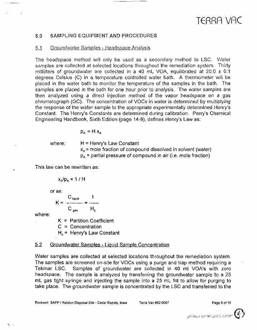
The headspace method will only be used as a secondary method to LSC. Watersamples are collected at selected locations throughout the remediation system. Thirtymilliliters of groundwater are collected in a 40 ml_ VGA, equilibrated at 20.0 ±0.1degrees Celsius (C) in a temperature controlled water bath. A thermometer will beplaced in the water bath to monitor the temperature of the samples in the bath. Thesamples are placed in the bath for one hour prior to analysis. The water samples arethen analyzed using a direct injection method of the vapor headspace on a gaschromatograph (GC). The concentration of VOCs in water is determined by multiplyingthe response of the water sample to the appropriate experimentally determined Henry'sConstant. The Henry's Constants are determined during calibration. Perry's ChemicalEngineering Handbook, Sixth Edition (page 14-9), defines Henry's Law as:
PA = H XA
where: H = Henry's Law ConstantXA= mole fraction of compound dissolved in solvent (water)pA = partial pressure of compound in air (i.e. mole fraction)
This law can be rewritten as:
XA/PA = 1 / H
or as:
K _
where:
C 1liquid '
C LJgas nc
K = Partition CoefficientC = ConcentrationHc = Henry's Law Constant
5.2 Groundwater Samples - Liquid Sample Concentration
Water samples are collected at selected locations throughout the remediation system.The samples are screened on-site for VOCs using a purge and trap method requiring aTekmar LSC. Samples of groundwater are collected in 40 ml VGA's with zeroheadspace. The sample is analyzed by transferring the groundwater sample to a 25mL gas tight syringe and injecting the sample into a 25 mL frit to allow for purging totake place. The groundwater sample is concentrated by the LSC and transferred to the
Rockwell SAPP / Ralston Disposal Site - Cedar Rapids, Iowa Terra Vac #62-0007 Page 9 of 15
faprinted on rccjcici popcr •
T€RRfl VflCGC for analysis. Analysis with the LSC follows an abbreviated method of EPA method8010/8020.
Representative analytical procedures to be used for off-site laboratory analyses ofrecovered groundwater will be in accordance with Test Methods for Evaluating SolidWaste, SW-846, U.S. EPA Method 8240A for VOCs.
5.3 On-site Vapor Analysis
Vapor samples will be collected for on-site analysis by a single channel, FID GC(Shimadzu 9A or equivalent). Compounds to be analyzed will be the compounds ofinterest for the site. Vapor samples will be obtained with a 1.0 ml gastight syringe(fitted with a valve) inserted into a 0.25 inch sample port equipped with a septum.Immediately after the vapor sample is taken, the syringe valve is closed to effectivelyisolate the sample. Sample time, identification number, vacuum level, temperature andflow rate will be recorded and entered into the data base for further evaluation. Thesesamples will be accompanied with sample tracking records and taken immediately tothe on-site laboratory for analysis using the direct injection method on the GC.
The system will be under high negative pressure and care must be taken whencollecting the vapor samples. The gas-tight syringes planned for use in this project willbe modified to allow for the placement of a mini-inert valve between the needle andluer-type hub. The valve can be closed after the plunger is drawn, but before thesyringe is withdrawn from the sampling port. Since the collected vapor is undervacuum, closure of the mini-inert valve is important to avoid drawing ambient air into thesyringe once it is withdrawn from the port. This avoids having to make volumecorrections; a potential source of error.
The techniques for vapor sampling planned for use under the project is a modificationof the method described in ASTM D1391-78, Measurement of Odor in Atmospheres. Ingeneral, the following steps will be followed during vapor sample collection:
1. Select a precleaned gas-tight syringe modified with a mini-inert valve. Prior touse, purge the syringe with a minimum of three syringe volumes of laboratory air.
2. Insert the syringe into the gas sampling port. Pull out the plunger to the highestgradation mark and discharge the content back into the sampling stream.Repeat at least once more.
3. Fill the syringe a third time. Place the mini-nert valve in the closed position andwithdraw the syringe from the source.
4. Withdraw the syringe and label. Record pertinent field data including time, date,location, sampler, vapor temperature, negative pressure, etc.
5. Submit sample to the on-site analytical laboratory for analysis using a GCequipped with an FID.
Rockwell SAPP / Ralston Disposal Site - Cedar Rapids, Iowa Terra Vac #62-0007 Page 10 of 15
€te/
T€RRfl VflC6. If duplicate or split is being collected, collect it simultaneously (or as near to
simultaneous as possible) with the sample.
5.4 Process Monitoring
Process monitoring will involve collecting vacuum, flow and temperature measurementsat each wellhead, before and after the treatment process, and at the stack inconjunction with vapor sampling. This data, as well as analysis of process vaporsamples, will combine to give information necessary to evaluate optimum systemoperation levels and treatment efficiencies.
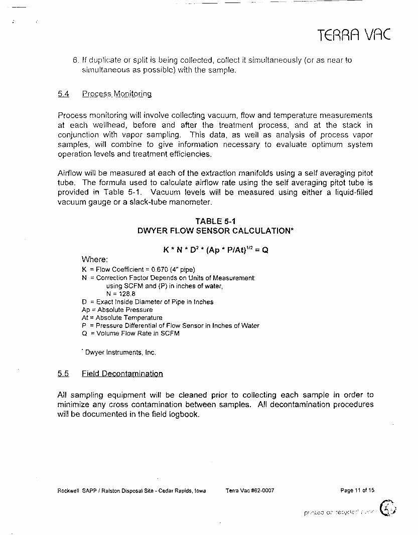
Airflow will be measured at each of the extraction manifolds using a self averaging pitottube. The formula used to calculate airflow rate using the self averaging pitot tube isprovided in Table 5-1. Vacuum levels will be measured using either a liquid-filledvacuum gauge or a slack-tube manometer.
TABLE 5-1DWYER FLOW SENSOR CALCULATION*
K * N * D2 * (Ap * P/At)1'2 = QWhere:K = Flow Coefficient = 0.670 (4" pipe)N = Correction Factor Depends on Units of Measurement:
using SCFM and (P) in inches of water,N = 128.8
D = Exact Inside Diameter of Pipe in InchesAp = Absolute PressureAt = Absolute TemperatureP = Pressure Differential of Flow Sensor in Inches of WaterQ = Volume Flow Rate in SCFM
' Dwyer Instruments, Inc.
5.5 Field Decontamination
All sampling equipment will be cleaned prior to collecting each sample in order tominimize any cross contamination between samples. All decontamination procedureswill be documented in the field logbook.
Rockwell SAPP / Ralston Disposal Site - Cedar Rapids, Iowa Terra Vac #62-0007 Page 11 of 15
, • ,pri'-stea or recede:1 c s \ - r -
T6RRFI VfiC
6.0 QUALITY ASSURANCE/QUALITY CONTROL SAMPLES
Quality Assurance/Quality Control (QA/QC) Samples will be performed to ensure thecollection of representative samples and the generation of valid analytical results onthese samples. The following sections detail the types of QA/QC samples that areroutinely used.
Quality control checks will be performed to ensure the collection of representativesamples and the generation of valid analytical data. An outline of greater detail ispresented in the attached Quality Assurance Project Plan (QAPP) for the RalstonDisposal site.
6.1 Calibration Procedures and Frequency
This section describes calibration procedures and policies pertinent to the analysis ofsamples collected during DVE system startup activities at the site. In order for QA/QCobjectives to be achieved, it is imperative that the response of all analytical equipmentbe calibrated to known standards.
In order to maintain direct quality control over the implementation of the QAPP, TerraVac will operate an on-site analytical laboratory, equipped with, but not limited to:
» One Shimadzu Model 9A Gas Chromatograph or equivalent,» One Shimadzu CR4A Chromatopac computer and printer or equivalent,* One Tekmar Liquid Sample Concentrator,* Constant temperature bath,» Analytical balance readable to 0.01 gram, and» Refrigerator for sample storage.
Field GC analyses will be carried out utilizing a capillary column (60M), one flameionization detector and a temperature-controlled compartment to insure retention timestability of peaks.
Initially, a three-point calibration curve will be made for each detector to verify linearity.The range of this curve will correspond to the expected range of concentrations foundin real samples. If the percent relative standard deviation (% RSD) of the calibrationfactors derived from each calibration point is less than 20% over the working range,linearity through the origin is assumed and the average calibration factor will be used inplace of a calibration curve.
The working calibration curve or calibration factor will be verified daily by the injection ofone or more calibration standards. Before any set of standards can be used in thepreparation of a calibration curve, the concentration must be verified by either analysisRockwell SAPP / Ralston Disposal Site - Cedar Rapids, Iowa Terra Vac #62-0007 Page 12 of 15
v.
T6RRF) VflCof a U.S. ERA QC check sample, or analysis of two independently prepared checkstandards. If the response for any analyte varies from the initial calibration by morethan ±15%, corrective action will be taken. A calibration check shall be run, at aminimum, every shift or every 8 hours, whichever is less.
Calibration and check standards will be performed using the following method for vaporanalysis: a static bulb dilution standard for the same components. The static bulbdilution standard method has been approved and is routinely used at several Superfundsites by Terra Vac, most notably, the Tyson Site, King of Prussia, Pennsylvania. Thismethod has been proven to result in low variability.
Calibration for the headspace method is completed by the injection of known quantitiesof components into 30 mL of distilled water in a 40 ml VOA. The calibration standardis then placed in a bath for one hour. A known volume of air is removed from theheadspace and injected into the GC for analysis.
Calibration using the LSC is completed by filling a volumetric flask with 100 ml ofdistilled water. A known amount of standard mix is injected into the flask andimmediately capped. The flask is gently inverted five times. The water standard istransferred to the purging vessel on the LSC using a 5 mL gas tight syringe.
For all of the above methods, the standard is prepared from neat standards available in99+% purity and packaged under nitrogen in Sure-Seal bottles (Aldrich).
6.2 Calibration Standards
Calibration standards will be made by combining equal volumes of the twelvecompounds of interest in a small vial fitted with a teflon-faced septum. A 1000 mlmicro-pipette equipped with disposable tips will be used to prevent cross contaminationduring standard preparation. The vial will be refrigerated when not in use and a freshcalibration standard will be prepared bi-weekly.
6J3 Blanks
Syringes are an indispensable part of any analytical protocol whether the matrix is soil,water or process gas. Therefore, steps are taken to ensure quality and suitability for aparticular analysis. The steps are:
* Each syringe and its plunger bear a unique code which becomes part of theanalysis.
* After each use, a syringe is purged using laboratory air for at approximately 1/2hour.
* Certain syringes may be dedicated to specific tasks to facilitate quality controlefforts.
Rockwell SAPP / Ralston Disposal Site - Cedar Rapids, Iowa Terra Vac #62-0007 Page 13 of 15

T6RRR VflC
* Syringes are equipped with side-port needles to prevent the problems of "coring"associated with the straight-needle types.
A method blank will be analyzed in the on-site laboratory before processing anygroundwater samples to demonstrate that all sampling glassware and syringes areinterference-free on a frequency of 1 in 20 samples.
Trip blanks for vapor samples will be a syringe containing laboratory air, carried throughthe field sampling routine, returned to the laboratory and analyzed along with the othersamples. The frequency of trip blanks will be 1 in every 20 samples.
Trip blanks for the groundwater sampling procedures will be performed by taking a 40ml vial filled with deionized water to the sample location and then returning the vial tothe laboratory for analysis. Again, the frequency of trip blanks will be 1 in 20 samples.
6.4 Replicates/Duplicates
For groundwater, duplicate samples will be collected using 40 ml VOA vials during thesame sample trip. For process gases, duplicate syringe samples will be collected fromidentical points in the process at the same time. Duplicates will be analyzed at afrequency of 1 in 20 samples per matrix.
6.5 Spike Recovery
As a quality control check on the accuracy of the method used in a particular matrix,spike recovery runs will be made on 5% of the samples. For groundwater samples, thereplicate samples collected will be subject to spike recovery analyses.
6.6 Field Equipment
Pressure gauges, thermometers and flow measuring devices will be routinelycross-checked with calibrated gauges and instruments. A field audit on 10 percent ofthe gauges will be conducted monthly. Any gauge or measuring device that issuspected to be out of the accuracy range of the manufacturer specifications will bechecked and recalibrated if necessary.
Rockwell SAPP / Ralston Disposal Site - Cedar Rapids, Iowa Terra Vac #62-0007 Page 14 of 15
prn;c;i or, rec-,K >£•• • - ' pop?1
TCRRfl VflC7.0 SAMPLE HANDLING AND ANALYSIS
Samples collected for analysis will be placed in the appropriate containers as shownbelow:
Media Sample Container/Preservation/Holding Time
* Water 40 mL vials (on-site VOC)/4°C/24 hoursWater 40 mL vials (off-site VOC)/4°C/7 days
* Vapor Gas-tight syringe/NA/1 hr
All sample jars will be equipped with Teflon lined lids.
Successful analyses depend on the capability to produce valid data. In addition toproper sample collection, preservation, storage and handling, and appropriate sampleidentification, sample tracking and chain-of-custody procedures are necessary to helpsupport the validity of the data. As samples are collected and containerized, the TerraVac sampling team will affix a sample label to each container. The sample label will beused to record the following information:
» Project number - 62-0007.» Sample number - pre-assigned identification number for sample designation.» Sample location - description of place where sample was collected.* Date* Preservative (if any)* Time - four digit number indicating military time of sample collection.* Collector - signature or initials of person or persons collecting samples.
Rockwell SAPP / Ralston Disposal Site - Cedar Rapids, Iowa Terra Vac #62-0007 Page 15 of 15
printed on


![Technical Sampling and Analysis Plan - Arkansas Department of Environmental Quality … · 2017-04-04 · Sampling and Analysis Plan (SAP) [Facility Name] [City, State] [Date] Page](https://img.pdfslide.us/doc/110x75/5e6a64f58f2fd857950c0008/technical-sampling-and-analysis-plan-arkansas-department-of-environmental-quality.jpg)