Embed Size (px)
Citation preview

DSPMC v2 – pn 7762S, 7762M
Ethernet Motion Controller Data Acquisition System
PID Controller
User Guide
Document Revision 1204 (Updated March 8, 2013)
© 2012 Vital Systems Inc Phoenix, AZ USA
For more information please visit the product web page:
www.vitalsystem.com/dspmc

DSPMC v2 Controller User Guide
© 2012 Vital Systems, Inc. 2 www.vitalsystem.com
CONTENTS
1. OVERVIEW ................................................................................................................................ 4
2. SOFTWARE SETUP ................................................................................................................... 5
2.1 DSPMC Mach3 Plugin Setup ................................................................................................. 5 2.2 DSPMC Boot Loader Setup ................................................................................................... 5 2.3 Custom Software Application with DSPMC ........................................................................... 5
3. NETWORK CONNECTION SETUP ............................................................................................ 6
3.1 Setup IP address using a Router with DHCP Server............................................................. 6 3.2 Manually assigning an IP Address to the PC ......................................................................... 7
4. HARDWARE INTERFACE DESCRIPTION .............................................................................. 10
4.1 Ethernet Port - J1 ................................................................................................................. 11 4.2 Analog I/O Port – J2 ............................................................................................................. 11 4.3 Stepper Outputs, Encoder Channel #6 on J3 and J14 ........................................................ 12 4.4 Digital I/O Ports - J4, J5, J11, J12 ....................................................................................... 13 4.5 Differential Quadrature Encoders on J6, J7, J3, and J8 ...................................................... 16 4.6 Single-Ended Encoder Inputs .............................................................................................. 18 5. Hardware Connections .......................................................................................................... 19
6. AXISWORKS SOFTWARE TOOL ............................................................................................ 20
7. MACH3 SOFTWARE INTEGRATION ...................................................................................... 21
7.1 Starting Mach3 with DSPMC ............................................................................................... 21 7.2 Mapping Mach Input Signals to DSPMC Digital Inputs........................................................ 24 7.3 Mapping Mach3 output pins to DSPMC Digital Outputs ...................................................... 27 7.4 Motor outputs. ...................................................................................................................... 29 7.5 Spindle Setup. ...................................................................................................................... 29
7.5.1 Setting an Axis as a Spindle.......................................................................................... 30 7.6 Getting beyond the basic input/output with Mach3. ............................................................. 30 7.7 Axis Homing and Direction ................................................................................................... 31 7.8 Manual Pulse Generation - MPG ......................................................................................... 33 7.9 OEM DROs and LEDs ......................................................................................................... 34 7.10 DSPMC Plugin Configuration ............................................................................................. 35 7.11 DSPMC Plugin Configuration System Tab ........................................................................ 36
7.11.1 Spindle Type and Index ............................................................................................... 36 7.11.2 Max Buffer Level ......................................................................................................... 37 7.11.3 Enable Debug Window ................................................................................................ 37 7.11.4 THC Mode and THC Test using emulated up/down signals ....................................... 37 7.11.5 Threading .................................................................................................................... 37 7.11.6 Probing ........................................................................................................................ 38 7.11.7 Manual Pulse Generation (MPG) ................................................................................ 39 7.11.8 Hardware Encoder Polarity ......................................................................................... 39 7.11.9 Encoder Debounce ...................................................................................................... 39 7.11.10 Update DSPMC Button (Under System Tab) ............................................................ 39
7.12 DSPMC Plugin Configuration Axis Tab ............................................................................. 40 7.12.1 PID Filter...................................................................................................................... 40 7.12.2 Test Motion .................................................................................................................. 41 7.12.3 Control Parameters ..................................................................................................... 43
7.13 Slave Axis Configuration .................................................................................................... 44
8. DSPMC SOFTWARE UPGRADE TOOL .................................................................................. 45
8.1 Upgrade the DSPMC Firmware ........................................................................................... 45 8.2 Changing the DSPMC Default IP Address .......................................................................... 48

DSPMC v2 Controller User Guide
© 2012 Vital Systems, Inc. 3 www.vitalsystem.com
LICENSE AGREEMENT ............................................................................................................... 49
WARNING: Machines in motion can be extremely dangerous! It is the responsibility of the user to design effective error handling and safety protection as part of the system. VITAL Systems shall not be liable or responsible for any incidental or consequential damages. By Using the DSPMCv2 motion controller, you agree to the license agreement.
Note: The Step and Direction Outputs on DSPMCv2 are not operational at the time of writing this Manual. Please check with the manufacturer for the latest information.

DSPMC v2 Controller User Guide
© 2012 Vital Systems, Inc. 4 www.vitalsystem.com
1. Overview The DSPMC is an Ethernet based controller for motion control, data acquisition, and general PID control system applications. Utilizing the latest DSP technology, the DSPMC offers a comprehensive set of features for your demanding applications.
DSPMC controller can be applied in a variety of applications involving PC based Motion Control, Storage and Retrieval Systems and CNC Milling / Lathe Machines. Equipped with a rich set of hardware interfaces, it can also be used for wide variety of applications involving PID control, e.g., speed, oven temperature control and so on.
Following in the key features of DSPMC v2:
8 Channels Servo Drive Analog Outputs, Range ±10V, 16-Bit Resolution
8 Differential Quadrature Encoder Inputs. 32-Bit Resolution
4 Mhz Max Encoder frequency. Encoder resolution multiplied by 4 thru Hardware.
8 Channel Analog Inputs, Range ±10Volts, 16-bit Resolution (7762M Only)
96 Digital I/O (64 Inputs & 32 Outputs)
Ethernet 100Mb connectivity using TCP/IP interface.
Wide input power range 10-40VDC
Simple UDP Socket Programming Interface.
Visual Studio 2010 .Net Managed Library for C#, C++, and VB.Net Software Developers.
Standalone Operation by programming the unit with BASIC programming language.
DSPMC board comes with GUI software tools to test the hardware, setup PID controller, run motion control commands, and upgrade new firmware. Following gives a brief description of the software tool set:
DSPMC Firmware Upgrade – A GUI based software tool to re-flash (burn) the firmware stored on the DSPMC board. New versions of this program and firmware can be obtained from the factory.
Mach3 Plugin – Plugin Software for Mach3 Mill/Lathe Software.
Windows .Net Library – Software Library for custom pc software development.
Extremely Important Reminder
When operating machines, take extreme precautions. The machines can have enormous power even with a small motor. Never come inside a machine path while
powered. Operating machines without necessary precautions can result in lost of limbs or even death.

DSPMC v2 Controller User Guide
© 2012 Vital Systems, Inc. 5 www.vitalsystem.com
2. Software setup
2.1 DSPMC Mach3 Plugin Setup To use the DSPMC plugin for Mach3, copy the M3dspMC.dll file to Mach3\PlugIns folder. When you run Mach3, it should provide you with a prompt for multiple plugins detected with the DSPMC plugin included in the list.
2.2 DSPMC Boot Loader Setup In order to change or update the firmware installed on the DSPMC, you will have to install the DSPMC Boot Loader. The program can be downloaded from www.vitalsystem.com/dspmc. For instructions on using the program, see Section 8. DSPMC Software Upgrade Tool.
2.3 Custom Software Application with DSPMC Custom Windows applications for DSPMC can be developed using the DSPMC .NET CLR library. A demo C# .Net application using this library can be downloaded from http://www.vitalsystem.com/dspmc.

DSPMC v2 Controller User Guide
© 2012 Vital Systems, Inc. 6 www.vitalsystem.com
3. Network Connection Setup You can connect the DSPMC board directly to your PC or connect via an Ethernet switch or router. The DSPMC board can use the firmware pre-assigned IP address, ie, 192.168.0.50, or it can get a unique IP address from an external DHCP server on your network. In the latter case, the firmware pre-assigned IP address is ignored. There are two ways to setup the IP addresses of your PC and the DSPMC board.
1. Using a Router with DHCP Server
2. Manually assigning an IP Address to your PC
3.1 Setup IP address using a Router with DHCP Server
Host PC / Work Station
Ethernet Router &
DHCP ServerTo Internet
The figure above shows a basic setup using a router on your network. Connect the Ethernet cable from the J1- Ethernet port of the DSPMC board to the DHCP server/Router. Connect another Ethernet cable from the DHCP Server/Router to the PC. The DHCP server dynamically assigns IP address both to the PC as well as to the DSPMC board, and therefore completes the network setup without requiring any intervention from the user.
Note: If your network device does not support Auto-MDIX feature, a crossover Ethernet cable may be required.

DSPMC v2 Controller User Guide
© 2012 Vital Systems, Inc. 7 www.vitalsystem.com
3.2 Manually assigning an IP Address to the PC
With TCP/IP networking, the PC and the DSPMC, both, need their own unique IP address. When connecting the PC directly to the DSPMC board, you will need to manually assign an IP address to your PC. The DSPMC board will use its firmware pre-assigned IP address, i.e., 192.168.0.50. The Ethernet cable is connected from the J1-ethernet port of the DSPMC board to the PC as shown below:
Host PC / Work Station
Ethernet
One-to-one connection
using Straight Thru
Ethernet Cable
The PC IP Address can be configured manually in windows XP as follows. For other operating systems, please consult the respective user guides for changing the IP address.
1. Double click on the ‘My Network Places’ icon in Windows XP and open the ‘available network connections’. 2. Double click on the corresponding LAN Connection over which the device will be setup. The following window appears.

DSPMC v2 Controller User Guide
© 2012 Vital Systems, Inc. 8 www.vitalsystem.com
3. Click on the Properties and select the Internet Protocol (TCP/IP) Connection in ‘General’ Tab

DSPMC v2 Controller User Guide
© 2012 Vital Systems, Inc. 9 www.vitalsystem.com
4. Click on the ‘Properties’ button and make the settings in your PC similar to the one shown in the figure below. After settings are done, click ‘OK’ button to finish the setup

DSPMC v2 Controller User Guide
© 2012 Vital Systems, Inc. 10 www.vitalsystem.com
4. Hardware Interface description The DSPMC board has several interface ports and indicator LEDs. Figure below shows front side view of the DSPMC board with interface ports and other components:
DSPMC Board
PWRJ6J1
PWR
J2 J4
J3 J5 J7
PID
ERR
DSP
J1 – Ethernet port connected to PC J2 – Provides analog input and DAC output J3 – Stepper Motor outputs, Differential Encoder Input (Index 6). J4 – Digital I/Os, provide 16 inputs (0 to 15) and 8 outputs (0 to 7) J5 – Digital I/Os, provide 16 inputs (16 to 31) and 8 outputs (8 to 15) J6 – Differential Encoder inputs (Index 0, 1 and 2). J7 – Differential Encoder inputs (Index 3, 4 and 5) PWR – Power Connector PWR LED – Green colored LED for Power indication; it glows steadily when Power is on PID LED – Orange colored LED for PIDs in-control; it glows steadily when PID is armed ERR LED – Red colored LED for error indication. DSP LED – Green colored LED indicating DSP processor operation; blinks constantly during
normal operation. There are few connectors available on the internal circuit board, which are accessible by opening the top cover, or the ribbon cable slot:
DSPMC v2 Internal Circuit Board
J14PIN 1
PIN 1
PIN 1
1
1415
2
16J11 242526
313 12 11.. .. .. .. .. .. ..
.. .. .. .. .. .. ..
J121
1415
2
16242526
313 12 11.. .. .. .. .. .. ..
.. .. .. .. .. .. ..
J81
2
3
4
9
10
5
6
7
8

DSPMC v2 Controller User Guide
© 2012 Vital Systems, Inc. 11 www.vitalsystem.com
J11 – Digital I/Os, provide 16 inputs (32 to 47) and 8 outputs (16 to 23) J12 – Digital I/Os, provide 16 inputs (48 to 63) and 8 outputs (24 to 31) J8 – Differential Encoder Channel Input (Index 7). J14 – Stepper Step and Direction Output Channels 6 and 7 (3.3Volts signals)
4.1 Ethernet Port - J1 Connect to PC directly or via an Ethernet Hub or a switch. The DSPMC board supports both 10 MBit and 100 Mbit network speeds. TCP/IP network protocol in UDP mode is used for PC communications.
4.2 Analog I/O Port – J2
Analog Inputs (Available on 7762-M Models Only) o Input voltage Range: -10 to +10 Volts. o Input impedance: 10M Ohm. o Binary Resolution: 16 bits o Conversion Rate: up to 20KHz
Analog Outputs o Analog Output range: +/-10 Volts. o Analog Output Resolution: 16 Bits o Maximum Output Current Per Output: 20mA
J2 Pin Assignments:
Pin# Function Pin# Function
1 +12V, 100mA max 20 Analog Input 0
14 +5V, 500mA max 8 Analog Input 1
2 -12V, 50mA max 21 Analog Input 2
15 Analog Output 0 9 Analog Input 3
3 Analog Output 1 22 Ground (return)
16 Analog Output 2 10 Analog Input 4
4 Analog Output 3 23 Analog Input 5
17 Ground (return) 11 Analog Input 6
5 Analog Output 4 24 Analog Input 7
18 Analog Output 5 12 Ground (return)
6 Analog Output 6 25 Ground (return)
19 Analog Output 7 13 +5V, 500mA max
7 Ground (return)

DSPMC v2 Controller User Guide
© 2012 Vital Systems, Inc. 12 www.vitalsystem.com
4.3 Stepper Outputs, Encoder Channel #6 on J3 and J14 J3 provides 6 channels Step and Direction Signals, and one differential encoder input. The Step/Dir output signals are 0...5V Range.
J3 Pin Assignments:
Pin# Function Pin# Function
1 Step 0 20 Direction 5
14 Step 1 8 Encoder Channel 6 A+
2 Step 2 21 Encoder Channel 6 A-
15 Step 3 9 Encoder Channel 6 B+
3 Step 4 22 Encoder Channel 6 B-
16 Step 5 10 Encoder Channel 6 X+
4 +5V, 500mA 23 Encoder Channel 6 X-
17 Ground (return) 11 +5V 500mA
5 Direction 0 24 Ground (Return)
18 Direction 1 12 Reserved
6 Direction 2 25 Reserved
19 Direction 3 13 Ground (Return)
7 Direction 4
J14 Pin Assignments: J14 is a 6 pin header, which is accessible by opening the top cover. It
provides two extra channels of Step/Direction signals. These Stepper channels use the 3.3V standard. Stepper Channels 0..5 are available on J3 outside connector, and use 5 Volts standard.
Pin# Function
1 +3.3V, 100mA
2 Gnd (Return)
3 Step 6
4 Direction 6
5 Step 7
6 Direction 7

DSPMC v2 Controller User Guide
© 2012 Vital Systems, Inc. 13 www.vitalsystem.com
4.4 Digital I/O Ports - J4, J5, J11, J12
On the DSPMC 7762 board, there are Four Digital I/O connectors, each providing sixteen inputs and eight outputs. Total, there are 64 digital inputs and 32 digital outputs. These I/Os are not optically isolated. To get optical isolation, you can use the digital I/O breakout board pn 7535 with DSPMC board. Please visit www.vitalsystem.com for more info on 7535. These boards connect directly to J4, J5, J11 and J12, and provide detachable screw terminals for easy wiring and maintenance. The digital inputs are also used for emulated quadrature encoder for low speed applications, eg, MPG wheel for CNC control. For more details, see section 4.6 Single-Ended Encoder Inputs. The DSPMC v2 board has the following electrical limits on its Digital I/O pins:
Digital Inputs Digital Outputs
Input Voltage Range: 0 … 3.3 Volts High Level Threshold: 2.8 Volts Low Level Threshold: 0.8 Volts
Output Voltage Range: 0 … 3.3 Volts Max Output Current Per Output: 24mA
The Digital inputs and outputs on DSPMC-v2 (J4, J5, J11, J12, and J14) use the 3.3volts standard. The user should make sure that these I/O signals do not connect to a 5volts source. However, 5volts through a 4.7K or higher value resister can be connected to any input or output pin. A direct connection of these pins to 5volts (without a resister) will damage the unit. The Vital Systems Opto-Isolated I/O boards 7535, and OPTO22 style modules e.g. G4ODC5 and G4IDC5, are compatible with DSPMC Digital I/O Ports.

DSPMC v2 Controller User Guide
© 2012 Vital Systems, Inc. 14 www.vitalsystem.com
J4 Pin Assignments:
Pin# Function Pin# Function
1 Ground (Return) 20 Input 4
14 Output 0 8 Input 5
2 Output 1 21 Input 6
15 Output 2 9 Input 7
3 Output 3 22 Input 8
16 Output 4 10 Input 9
4 Output 5 23 Input 10
17 Output 6 11 Input 11
5 Output 7 24 Input 12
18 Input 0 12 Input 13
6 Input 1 25 Input 14
19 Input 2 13 Input 15
7 Input 3
J5 Pin Assignments:
Pin # Function Pin# Function
1 Ground (Return) 20 Input 20
14 Output 8 8 Input 21
2 Output 9 21 Input 22
15 Output 10 9 Input 23
3 Output 11 22 Input 24
16 Output 12 10 Input 25
4 Output 13 23 Input 26
17 Output 14 11 Input 27
5 Output 15 24 Input 28
18 Input 16 12 Input 29
6 Input 17 25 Input 30
19 Input 18 13 Input 31
7 Input 19

DSPMC v2 Controller User Guide
© 2012 Vital Systems, Inc. 15 www.vitalsystem.com
J11 Pin Assignments:
Pin # Function Pin# Function
1 Ground (Return) 20 Input 36
14 Output 16 8 Input 37
2 Output 17 21 Input 38
15 Output 18 9 Input 39
3 Output 19 22 Input 40
16 Output 20 10 Input 41
4 Output 21 23 Input 42
17 Output 22 11 Input 43
5 Output 23 24 Input 44
18 Input 32 12 Input 45
6 Input 33 25 Input 46
19 Input 34 13 Input 47
7 Input 35 26 +5V, 500mA
J12 Pin Assignments:
Pin # Function Pin# Function
1 Ground (Return) 20 Input 52
14 Output 24 8 Input 53
2 Output 25 21 Input 54
15 Output 26 9 Input 55
3 Output 27 22 Input 56
16 Output 28 10 Input 57
4 Output 29 23 Input 58
17 Output 30 11 Input 59
5 Output 31 24 Input 60
18 Input 48 12 Input 61
6 Input 49 25 Input 62
19 Input 50 13 Input 63
7 Input 51 26 +5V, 500mA

DSPMC v2 Controller User Guide
© 2012 Vital Systems, Inc. 16 www.vitalsystem.com
4.5 Differential Quadrature Encoders on J6, J7, J3, and J8
J6 Pin Assignments:
Pin# Function Pin# Function
1 Ch 0 A+ 8 +5V 500mA
14 Ch 0 A- 21 Ground (Return)
2 Ch 0 B+ 9 Ch 2 A+
15 Ch 0 B- 22 Ch 2 A-
3 Ch 0 Z+ 10 Ch 2 B+
16 Ch 0 Z- 23 Ch 2 B-
4 +5V 500mA 11 Ch 2 Z+
17 Ground (Return) 24 Ch 2 Z-
5 Ch 1 A+ 12 +5V 500mA
18 Ch 1 A- 25 Ground (Return)
6 Ch 1 B+ 13 Reserved
19 Ch 1 B-
7 Ch 1 Z+
20 Ch 1 Z-
J7 Pin Assignments:
Pin# Function Pin# Function
1 Ch 3 A+ 8 +5V 500mA
14 Ch 3 A- 21 Ground (Return)
2 Ch 3 B+ 9 Ch 5 A+
15 Ch 3 B- 22 Ch 5 A-
3 Ch 3 Z+ 10 Ch 5 B+
16 Ch 3 Z- 23 Ch 5 B-
4 +5V 500mA 11 Ch 5 Z+
17 Ground (Return) 24 Ch 5 Z-
5 Ch 4 A+ 12 +5V 500mA
18 Ch 4 A- 25 Ground (Return)
6 Ch 4 B+ 13 Reserved
19 Ch 4 B-
7 Ch 4 Z+
20 Ch 4 Z-

DSPMC v2 Controller User Guide
© 2012 Vital Systems, Inc. 17 www.vitalsystem.com
J3 Pin Assignments:
Pin# Function Pin# Function
1 Step 0 20 Direction 5
14 Step 1 8 Encoder Channel 6 A+
2 Step 2 21 Encoder Channel 6 A-
15 Step 3 9 Encoder Channel 6 B+
3 Step 4 22 Encoder Channel 6 B-
16 Step 5 10 Encoder Channel 6 X+
4 +5V, 500mA 23 Encoder Channel 6 X-
17 Ground (return) 11 +5V 500mA
5 Direction 0 24 Ground (Return)
18 Direction 1 12 Reserved
6 Direction 2 25 Reserved
19 Direction 3 13 Ground (Return)
7 Direction 4
J8 Pin Assignments: J8 is a 10 pin header, which is accessible by opening the top cover.
Pin# Function
4 Encoder Channel 7 A+
3 Encoder Channel 7 A-
6 Encoder Channel 7 B+
5 Encoder Channel 7 B-
8 Encoder Channel 7 X+
7 Encoder Channel 7 X-
2 +5V 500mA
1 Ground (Return)
9 Unused
10 Unused

DSPMC v2 Controller User Guide
© 2012 Vital Systems, Inc. 18 www.vitalsystem.com
4.6 Single-Ended Encoder Inputs
In addition to dedicated hardware encoder inputs, DSPMC board also provide three Single Ended encoder inputs in Digital Input J4 and J5 connector. These are simulated encoder inputs, therefore called, SoftEncoder, and are used for low speed applications like MPG. The following table lists the Digital I/O pins assigned to SoftEncoders. (Requires Firmware Rev 63 or newer): SoftEncoder 0 : A+ On J4 Pin 24,
B+ On J4 Pin 12 SoftEncoder 1 : A+ On J4 Pin 25
B+ On J4 Pin 13 SoftEncoder 2 : A+ On J5 Pin 18
B+ On J5 Pin 6 SoftEncoders are normally used as MPG source. See Section 7.11.7 Manual Pulse Generation (MPG) for more information. In addition, SoftEncoders are designed to avoid Jerks when MPG scale is changed by the PC software. To accomplish this, these encoder counters are implemented using floating point numbers (instead of whole integer numbers). They can be assigned decimal values (eg 3.092, 5.001, 64000.5 etc) which the hardware encoder counters are not capable of (they can only take whole integers).

DSPMC v2 Controller User Guide
© 2012 Vital Systems, Inc. 19 www.vitalsystem.com
5. Hardware Connections The figure below shows a typical axis setup using Analog Servo amplifier and quadrature encoder feedback. The connectors on DSPMC board are all DB25 connectors. The user can wire up the system using the 7711 (or 7721) and 7535 breakout boards as shown in the figure. The Encoder Cable should be shielded with the shield properly grounded.
AMP Enable Digital
output (0..15)
DAC Output +/-10V (0..7)
Quadrature Differential
Encoder Connections
J2
J4
J5
J6
J7
J1
PWR
ANALOG SERVO
AMPAC/DC POWER
INPUT
MOTOR POWER
Quadrature Differential
Encoder, e.g. 500 cps
12-24VDC Controller Power
M
7761 DSPMC/IP
Controller
7711 Breakout Board
7711 Breakout Board
7535 Opto Isolated
Digital I/O Board
TO PC Ethernet Port
Home, Limit, E-Stop, etc
Inputs (0..31)
ESTOP

DSPMC v2 Controller User Guide
© 2012 Vital Systems, Inc. 20 www.vitalsystem.com
6. AxisWorks Software tool This section has been removed as this software is now part of Mach3 Plugin.

DSPMC v2 Controller User Guide
© 2012 Vital Systems, Inc. 21 www.vitalsystem.com
7. Mach3 Software Integration
The Mach3 Software is an off-the-shelf Milling and Lathe machine control software. User can download the trail version of the software from www.machsupport.com The DSPMC board can be integrated with Mach3 to form a high performance machining center. The DSPMC Software Tools provide the necessary drivers and configuration files to interface with Mach3 software. If you have installed the software tools as explained in the software installations section, you already have all the necessary drivers. This document assumes that user is familiar with the usage of Mach3 software. This chapter describes the mapping of Mach3 internal software signals to the DSPMC connector. The general Mach3 software operation remains mostly the same when using DSPMC plugin.
7.1 Starting Mach3 with DSPMC To launch Mach3 with DSPMC plugin, double-click on the Mach3 Mill or Lathe software icon on the desktop as you would normally run using parallel port. It shows the following dialog box with the option to select M3dspMC plugin. Make sure this plugin is selected and click ‘OK’.
Make sure the DSPMC is powered up and connected to the Ethernet network. The Mach3 software shows up as follows with a message ‘DSPMC/IP Device Connected’ in the Status bar.
With DSPMC Mach3 Plugin Release 3, the users do not need to use AxisWorks Software for tuning and other configuration settings. The new plugin provide easy to use and very intuitive configuration screens to fully configure DSPMC to work with Mach3 software.

DSPMC v2 Controller User Guide
© 2012 Vital Systems, Inc. 22 www.vitalsystem.com
Click on the Menu item ‘PlugIn Control’, and then click on the item ‘VITAL DSPMC Status” which displays the following screen indicating that the DSPMC board is connected with current states of counters and I/O status.

DSPMC v2 Controller User Guide
© 2012 Vital Systems, Inc. 23 www.vitalsystem.com
User can toggle the outputs by clicking on the output LEDs. If an output is defined in Ports and Pins, it will controlled by Mach3 and clicking on its LED will not effect. User can leave this window open while running Mach3.

DSPMC v2 Controller User Guide
© 2012 Vital Systems, Inc. 24 www.vitalsystem.com
7.2 Mapping Mach Input Signals to DSPMC Digital Inputs The following table shows the mapping from Mach3 input pin numbers to the actual digital input pin numbers available on the DSPMC board.
Mach3 Input ports and pins
DSPMC J4 and J5 pin
assignments
Breakout board 7535 pin assignments
dspMacro MACH3 LED
Port # Pin Number
J4 Pin
number
J5 Pin
number
Board #1 Board #2
GetDSPData Index
OEMLED
1 0 18 0 0 1300
1 1 6 1 1 1301
1 2 19 2 2 1302
1 3 7 3 3 1303
1 4 20 4 4 1304
1 5 8 5 5 1305
1 6 21 6 6 1306
1 7 9 7 7 1307
1 8 22 8 8 1308
1 9 10 9 9 1309
1 10 23 10 10 1310
1 11 11 11 11 1311
1 12 24 12 12 1312
1 13 12 13 13 1313
1 14 25 14 14 1314
1 15 13 15 15 1315
1 16 18 0 16 1316
1 17 6 1 17 1317
1 18 19 2 18 1318
1 19 7 3 19 1319
1 20 20 4 20 1320
1 21 8 5 21 1321
1 22 21 6 22 1322
1 23 9 7 23 1323
1 24 22 8 24 1324
1 25 10 9 25 1325
1 26 23 10 26 1326
1 27 11 11 27 1327
1 28 24 12 28 1328
1 29 12 13 29 1329
1 30 25 14 30 1330
1 31 13 15 31 1331

DSPMC v2 Controller User Guide
© 2012 Vital Systems, Inc. 25 www.vitalsystem.com
Mach3 Input ports and pins
DSPMC J11 and J12 pin assignments
Breakout board 7535 pin
assignments
dspMacro MACH3 LED
Port # Pin Number
J11 Pin
number
J12 Pin
number
Board #3
Board #4
GetDSPData Index
OEMLED
1 32 18 0 140 1332
1 33 6 1 141 1333
1 34 19 2 142 1334
1 35 7 3 143 1335
1 36 20 4 144 1336
1 37 8 5 145 1337
1 38 21 6 146 1338
1 39 9 7 147 1339
1 40 22 8 148 1340
1 41 10 9 149 1341
1 42 23 10 150 1342
1 43 11 11 151 1343
1 44 24 12 152 1344
1 45 12 13 153 1345
1 46 25 14 154 1346
1 47 13 15 155 1347
1 48 18 0 156 1348
1 49 6 1 157 1349
1 50 19 2 158 1350
1 51 7 3 159 1351
1 52 20 4 160 1352
1 53 8 5 161 1353
1 54 21 6 162 1354
1 55 9 7 163 1355
1 56 22 8 164 1356
1 57 10 9 165 1357
1 58 23 10 166 1358
1 59 11 11 167 1359
1 60 24 12 168 1360
1 61 12 13 169 1361
1 62 25 14 170 1362
1 63 13 15 171 1363
If using any of the Mach3 input signals, make sure the pins are ‘Enabled’ and set ‘Active Low’ as shown in the example figure below.

DSPMC v2 Controller User Guide
© 2012 Vital Systems, Inc. 26 www.vitalsystem.com
Ignore the line printed on the above window about pins 10-13 and 15 !@#$. This does not apply to DSPMC based system.

DSPMC v2 Controller User Guide
© 2012 Vital Systems, Inc. 27 www.vitalsystem.com
7.3 Mapping Mach3 output pins to DSPMC Digital Outputs The following table shows the mapping from Mach3 output pin numbers to the actual digital output pin numbers available on the DSPMC board.
Mach3 Output ports and pins
DSPMC J4 and J5 pin assignments
Breakout board 7535 pin assignments
dspMacro
Port # Pin Number J4 Pin number
J5 Pin number
Board #1 On J4
Board #2 On J5
SetDSPData Index
1 0 14 0 40
1 1 2 1 41
1 2 15 2 42
1 3 3 3 43
1 4 16 4 44
1 5 4 5 45
1 6 17 6 46
1 7 5 7 47
1 8 14 0 48
1 9 2 1 49
1 10 15 2 50
1 11 3 3 51
1 12 16 4 52
1 13 4 5 53
1 14 17 6 54
1 15 5 7 55
Mach3 Output ports and pins
DSPMC J11 and J12 pin assignments
Breakout board 7535 pin assignments
dspMacro
Port # Pin Number J11 Pin number
J12 Pin number
Board #3 On J11
Board #4 On J12
SetDSPData Index
1 16 14 0 56
1 17 2 1 57
1 18 15 2 58
1 19 3 3 59
1 20 16 4 60
1 21 4 5 61
1 22 17 6 62
1 23 5 7 63
1 24 14 0 64
1 25 2 1 65
1 26 15 2 66
1 27 3 3 67
1 28 16 4 68
1 29 4 5 69
1 30 17 6 70
1 31 5 7 71

DSPMC v2 Controller User Guide
© 2012 Vital Systems, Inc. 28 www.vitalsystem.com
As with the input configuration, if using any of the Mach3 output signals, make sure the pins are ‘Enabled’ and set ‘Active Low’ as shown in the example figure below.
Ignore the line printed on the above window about pins 2-9,1,14… !@#$. This does not
apply to DSPMC based system.

DSPMC v2 Controller User Guide
© 2012 Vital Systems, Inc. 29 www.vitalsystem.com
7.4 Motor outputs. On the Motor Ouputs tab, enable the axis that you will be using. Spindle setting in this window is not used by the DSPMC plugin.
7.5 Spindle Setup. When using a VFD or other motor controlling device that uses 0-10v or ±10v control, the following steps are needed. The selection of analog output channel is done via the Plugin config screen. Make sure Spindle Relays are enabled in the Port and Pins Spindle window. Go to the Config tab and then spindle pulleys. Current pulley 1. For this example, set min speed to 0 and max speed to 100. This will give a 0v output to the spindle at S0 (min speed) and a 10v at S100 (max speed). This setting is great for testing. Without the VFD/Drive hooked up you can test your output with a digital volt meter to make sure you are getting 0-10volts for 0 to max speed. When it all works then put in min 0 and max gets set to the max speed of your machine, eg, 5000. This will allow you to program S in the G-code in actual rpm, ie 0 … 5000. On the Plugin Config System tab, you can configure the spindle to use ±10V or 0-10V by selecting the Spindle Type.

DSPMC v2 Controller User Guide
© 2012 Vital Systems, Inc. 30 www.vitalsystem.com
7.5.1 Setting an Axis as a Spindle
You may set any axis (0 – 5) as the spindle axis by specifying from the Spindle Type field and selecting “GCode Axis”. The Axis number is specified in the Spindle Index field on the System tab. Once the spindle axis has been set, you may then issue any GCode command (e.g. G0C10) for spindle position control, as well as Spindle speed commands (e.g. S500M3) to control the spindle speed and direction using the closed loop axis PID control. The Steps Per, Max Speed, and Acceleration of the spindle is read from the selected axis motor-tuning configuration. NOTE: The spindle’s motor-tuning settings are always ignored.
7.6 Getting beyond the basic input/output with Mach3. When your are done with limit switches and other basic I/O you will probably want to have several switches on you control panel next to the e-stop such as feed hold, stop, g-Code rewind and other things. To get this added functionality you will need to learn how to write brains in Mach3. Brains are used to get access to all of the extra I/O and to work tool changers and just about anything you can think of. Here is a pretty basic brain to map input 1 to output 5.
You would setup what wire goes to input 1 and output 5 under the ports and pins tab of Mach3. After a few tries you will get the hang of it. For more information: go to www.machsupport.com and then to the video section and look for Brains.

DSPMC v2 Controller User Guide
© 2012 Vital Systems, Inc. 31 www.vitalsystem.com
7.7 Axis Homing and Direction In the Config menu, select Homing/Limits. You will see the following window.
To change the axis direction, click on the Reversed column for the axis you want to change the direction. A green check mark indicates the direction is now reversed. NOTE: The Encoder Polarity in the Plugin Config System tab must be updated to match the new axis direction. Homing Offset lets you define the home position co-ordinates for the Master Axis. When homing sequence is complete, the axis machine position is set to this value.

DSPMC v2 Controller User Guide
© 2012 Vital Systems, Inc. 32 www.vitalsystem.com
When using a Slave Axis, and homing the slave independently, the Home Offset is used for an extra move to square the gantry. The direction of motion is defined by the sign (+/-) of this field. Home Neg, changes the default homing direction. The DSPMC offers a number of different homing types for each axis. Please review section 7.12.3 Control Parameters to select the correct homing sequence. If you are using Index-Pulse-Only Homing without a home sensor, you must assign an unused digital input in Mach3 as home sensor. Mach3 software requires a home sensor definition regardless of homing method. Any Limit switch can also be used as a home sensor.

DSPMC v2 Controller User Guide
© 2012 Vital Systems, Inc. 33 www.vitalsystem.com
7.8 Manual Pulse Generation - MPG DSPMC allows using a quadrature encoder as a MPG source. The encoder is connected to the dedicated encoder inputs on J3, J6 and J7 (HardEncoder), as well as to J4 and J5 digital inputs (SoftEncoder). Users can configure MPG parameters as explained in section 7.11.7 Manual Pulse Generation (MPG).
To turn on MPG feature, make sure MPG #1 is checked green as shown above in the Ports and Pins window. Enter the Encoder resolution in the Counts/Unit field. The rest of the fields in this window are not used. The SoftEncoder are available on digital inputs of connector J4 and J5. The pin assignments are as follows:
SoftEncoder 0 : A = J4 Pin 24, B = J4 Pin 12 SoftEncoder 1 : A = J4 Pin 25, B = J4 Pin 13 SoftEncoder 2 : A = J5 Pin 18, B = J5 Pin 6 You set the encoder multiplier in the General Config setting as shown below. You can use your own multiplier values in this window as well as use the standard .1, .01, .001, etc values. When MPG mode is selected, and a G-Code file is run, the DSPMC Plugin will switch to jog mode automatically in order to run the file. Once the file is complete or stopped, the mode will revert back to MPG.

DSPMC v2 Controller User Guide
© 2012 Vital Systems, Inc. 34 www.vitalsystem.com
7.9 OEM DROs and LEDs The following tables lists the OEM DROs and LEDs used by the DSPMC plugin.
OEMDRO Index Description
1320 thru 1327 Analog Input data from ADC channels 0..7. Available only with 7761-M model.
1330 thru 1332 Digital Input Encoders (SoftEncoder) on J4 and J5. SoftEncoder 0 : A+ On J4 Pin 24,
B+ On J4 Pin 12 SoftEncoder 1 : A+ On J4 Pin 25
B+ On J4 Pin 13 SoftEncoder 2 : A+ On J5 Pin 18
B+ On J5 Pin 6
1340 Threading RPM. This RPM is calculated based on the parameters defined in the Threading section of DSPMC Plugin Configuration, and is used by the Threading Logic.
OEMLED Index Description
1300 – 1363 Digital Inputs 0 – 63
2035 Launch HiCON Macro from Mach3

DSPMC v2 Controller User Guide
© 2012 Vital Systems, Inc. 35 www.vitalsystem.com
7.10 DSPMC Plugin Configuration DSPMC plugin configuration screens can be launched from Mach3 by navigating to Config -> Config Plugins and selecting M3dspMC-DSPMC-Plugin-xxx-VITAL- option.
Once DSPMC plugin configuration is launched you can see nine tabs, these are:
1. System Tab 2. Axis X(0) 3. Axis Y(1) 4. Axis Z(2) 5. Axis A(3) 6. Axis B(4) 7. Axis C(5) 8. Axis D(6) 9. Axis E(7)
Each Axis tab represents an axis to be controlled through DSPMC. By default, System tab will be selected, as shown in DSPMC Configuration window.
DSPMC v2 Controller User Guide
© 2012 Vital Systems, Inc. 36 www.vitalsystem.com
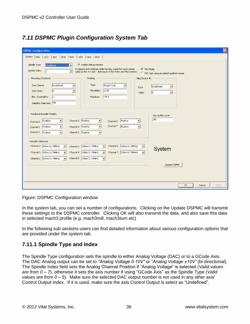
7.11 DSPMC Plugin Configuration System Tab
Figure: DSPMC Configuration window In the system tab, you can set a number of configurations. Clicking on the Update DSPMC will transmit these settings to the DSPMC controller. Clicking OK will also transmit the data, and also save this data in selected mach3 profile (e.g. mach3mill, mach3turn etc) In the following sub sections users can find detailed information about various configuration options that are provided under the system tab.
7.11.1 Spindle Type and Index
The Spindle Type configuration sets the spindle to either Analog Voltage (DAC) or to a GCode Axis. The DAC Analog output can be set to “Analog Voltage 0-10V” or “Analog Voltage ±10V” (bi-directional). The Spindle Index field sets the Analog Channel Position if “Analog Voltage” is selected (Valid values are from 0 – 7), otherwise it sets the axis number if using “GCode Axis” as the Spindle Type (Valid values are from 0 – 5). Make sure the selected DAC output number is not used in any other axis’ Control Output Index. If it is used, make sure the axis Control Output is select as “Undefined”.

DSPMC v2 Controller User Guide
© 2012 Vital Systems, Inc. 37 www.vitalsystem.com
7.11.2 Max Buffer Level
This parameter defines how much command position buffering will be done inside the DSPMC controller. The total size of the buffer is 4096 points per axis. These points are consumed by the DSPMC at 1 KHZ. To get faster response time on feedrate changes, you may select a lower value, but the side effect is that if the PC software slows down and cannot sustain the motion data rate to the DSPMC, then the motion could be jerky. The valid rage for this parameter is 1…100 percent.
7.11.3 Enable Debug Window
By checking this option users can enable debug window for debugging purpose. This option should be turned on only if directed by a factory personal. The debug window will appear next time you start Mach3.
7.11.4 THC Mode and THC Test using emulated up/down signals
For information on using DSPMC for Torch Height Control Purposes, see the User Guide for THC Adapter Board (THCADP1).
7.11.5 Threading
Following sub sections describes parameters to configure threading in DSPMC. Threading RPM Synch Source This parameter defines the encoder type for Spindle speed calculation and starting the threading cycle. The Index pulse from the encoder is used to launch the Z-Axis at the right time in order to position the tool correctly for Threading in every cycle. The RPM calculation is used to override the feedrate of the Z-Axis during the threading cycle. Two possible values for RPM Sync Source parameter are: “HardEncoder” and “DigitalInput”.
Undefined: When this option is selected DSMPC will not enable threading and value of RPM Synch Index will be ignored. When HardEncoder is selected, the spindle feedback encoder must be connected to one of the encoder inputs on J3, J6, J7 and J8 connectors. The encoder’s differential A and B signals are used to calculate the RPM of the spindle, and Index pulse is used to trigger the threading cycle. When DigitalInput is selected, the spindle feedback is generated by a single line pulse train. The pulse train is used to calculate the spindle RPM as well as used for Sync pulse to launch the threading cycle. There are two dedicated inputs on J5 for the spindle pulse train. These are also called I/O Toggle Counters.
I/O Toggle Counter 0: Digital Input 18 (J5 Pin 19) I/O Toggle Counter 1: Digital Input 19 (J5 Pin 7)

DSPMC v2 Controller User Guide
© 2012 Vital Systems, Inc. 38 www.vitalsystem.com
Threading RPM Synch Index This parameter defines the encoder index for Spindle speed feedback. Below is the range for this index: HardEncoder: index range is 0...7. DigitalInput: 18(J5 Pin 19) and 19(J5 Pin 7) Threading RPM Count/Rev This parameter defines the encoder resolution in terms of count per revolution for Spindle speed feedback. For HardEncoder type encoder, the encoder resolution must is multiplied by 4. No multiplication is done when DigitalInput is selected. Threading RPM Sampling (ms) This parameter defines the timing window in milliseconds to add the encoder counts for RPM calculation. For slow pulse train (eg only few ticks per rev), this value should be high enough to accumulate enough counts to calculate RPM consistently. If the window time is too long, the system reaction time (regulation of Z-Axis feedrate) to changing RPM will be slow. A higher count/rev encoder will allow this window time to be very small, which will allow the system to react fast (regulate Z-Axis feedrate) if RPM changes. The range of this field is from 1 thru 10000 milliseconds. Mach3 Threading Bug Workaround: DSPMC plugin uses LED 1370 to workaround threading logic problem with mach3. In your G-Code program, turn on LED 1370 right before the threading g-code command and turn it off after the threading cycle is done. This will cause the programmed RPM +20% to be sent to Mach3 instead of true RPM during the threading cycle. This makes sure mach3 will generate correct feedrate for Z axis. Once this LED is off, true RPM will be shown on mach3 spindle rpm DRO.
7.11.6 Probing
This section defines parameter for CNC Probing feature. For the probing cycle, the axis, probing feedrate, and the probe switch are set by Mach3.
Probing Type: This parameter defines the probing method: SingleCycle: Axis starts the probing move. As soon as the probe switch is on, the current position is captured and the probing sequence is complete. DualCycle: Axis starts a first probing move (called coarse move). As soon as the probe switch is on, the axis stops, and backs off distance specified in the ProbingMoveBack parameter. The axis then starts the second move, called fine move. The direction is same as the coarse move. The feedrate for the fine move is defined by the third parameter Probing Feed Rate. Probing Move Back This parameter defines the distance to move back to start the fine move. It is applicable only in the DualCycle mode. Probing Feed Rate This parameter defines the feedrate for the fine move. It is applicable only in the DualCycle mode.

DSPMC v2 Controller User Guide
© 2012 Vital Systems, Inc. 39 www.vitalsystem.com
7.11.7 Manual Pulse Generation (MPG)
MPG Source Type This section defines MPG (Manual Pulse Generation) Quadrature encoder source. Both Differential and Single Ended Encoder types are supported. Differential encoder can be hooked up to any of the six encoder channel available on connectors J3, J6, J7 and J8. These encoders are defined as Hard Encoder. Single Ended encoders (defined as Soft Encoder) can be hooked up to the Digital Inputs available on Connector J5. An Undefined Encoder option causes DSMPC to ignore MPG Source values. MPG Source Index If Hard Encoder is selected in MPG Source Type, MPG Index denotes the hardware encoder index. If Soft Encoder is selected, MPG Index denotes available digital input options. The pin assignments for available SoftEncoder are as follows
SoftEncoder 0 : A On J4 Pin 24, B On J4 Pin 12
SoftEncoder 1 : A On J4 Pin 25 B On J4 Pin 13
SoftEncoder 2 : A On J5 Pin 18 B On J5 Pin 6
7.11.8 Hardware Encoder Polarity
The Hardware Encoder Polarity field is used to reverse the direction of the encoder counters. If A/B signals are connected in reverse such that it does not match the PID/Axis control direction, the system will not be able to arm. To fix this issue, the hardware A and B signals can be reversed using this parameter. Note that this encoder polarity setting only swaps the A and B signals to change the counter direction. The Index pulse signal polarity is not affected by this setting.
7.11.9 Encoder Debounce
The Encoder debounce field is used to remove noise from the hardware encoder signals. Setting of 100ns is normally sufficient, but if encoder count is still changing by noise, you can try higher debounce value. The higher the value in debounce, the maximum frequency of encoder signal will be reduced. This setting only applies to hardware encoders 0…7.
7.11.10 Update DSPMC Button (Under System Tab)
This button downloads the entire system configuration parameters to DSPMC. If you make any changes to Controls parameters, you must download the new settings by clicking on this button before ARMing the DSPMC or executing a test motion. To save data to your computer hard-drive, click OK. All configuration data from all pages is saved in the selected mach3 profile.

DSPMC v2 Controller User Guide
© 2012 Vital Systems, Inc. 40 www.vitalsystem.com
Important Note:
Make sure not to use 0 in the Max-Following-Error (MFE) field. Always use a non-zero positive number. If it is set to 0, the motor can move at max uncontrolled speed (in a run-away situation), which can be extremely dangerous.
7.12 DSPMC Plugin Configuration Axis Tab
The Axis tabs provide configuration settings that are directly related to each axis. These tabs also provide motion testing features. There are two sets of parameters, PID parameters and the Controls parameters. When testing motion by pressing the ‘Execute’ button, the PID parameters are transmitted to DSPMC automatically before motion is launched. The Controls parameters must be transmitted to DSPMC manually by pressing ‘Update DSPMC’ button before PID is armed. Clicking on OK or the ‘Save Configuration’ buttons saves the entire configuration to the selected Mach3 profile.
7.12.1 PID Filter
Effective FW revision 6.48: PID Scale is not used (should be set to 1 for backward compatibility) These values define the co-efficient of PID filters for the selected axis. The PID filter runs at 5KHz for each axis. For tuning, set the scale to 1 and P 100, MFE at 5000, low pass at 5. all others parameters at zero. Do test- motion commands. If no motion is observed, start increasing P until you do see motion. If the actual

DSPMC v2 Controller User Guide
© 2012 Vital Systems, Inc. 41 www.vitalsystem.com
motion is in the opposite direction of commanded, change the encoder polarity in the system tab. Once you get a decent graph, (i.e. actual follows commanded), start adding I, Max Error I, D and VFF terms to fine tune the graph. Ideally, actual graph line should be as close to commanded as possible. When you set I term greater than 0, make sure Max error I is also non zero, otherwise you will get uncontrolled oscillations, eg start I with 5 and MaxError I as 100, and gradually increase or decrease. Do the test motions for small and large moves, ie few mm to 100 of mms. To achieve good tuning, do the test motion for very small distances (eg 3-5mm) and at extremely high velocity and acceleration, and try to get the actual graph as close as possible to commanded line. This way the PID values will be achieved to get the axis in position in minimum amount of time. The following sections describe some of the PID parameter: Effective FW revision 6.48: Scale is not used (should be set to 1 for backward compatibility) Max_error - Maximum error limit. Leave it at 0. Max_Error_I - Maximum Integral Error for the integral gain. This must be greater than 0 if you put any non zero value in the I term. Deadband – a range of position around the commanded position where the PID is not active (when armed), e.g. if current command position is 1000 count, and Deadband is 10, the PID will be inactive between 990 and 1010 count. Max Following Error – Maximum deviation allowed between command and actual, above that, the PID controller shuts down and need to be re-enabled manually. If 0, PID will never shutdown which can be extremely dangerous in a run-away motor condition. So always use a positive value in this field. This field can be back calculated from the maximum velocity of the axis, e.g. 600 000 count/sec max velocity divide by 1000 gives 600 counts per millisecond. So to achieve 600K count/sec speed, the max following error should be 600 or more. The actual value may be lot more than that based on how tight the PID tuning is, and the mechanical characteristics of the axis. Output Offset - Sets a constant bias to the PID output. This is useful to cancel any offset output voltage on the DSPMC analog output channels (J2, DAC 0..7). Low Pass Filter – This field is used to smooth the analog output so the motors run smooth and less noisy. As the PID runs at 5KHz, a value of 5 will create a nice linearly increasing DAC output at 1KHz. If you put a value of 10, effective PID speed will become 500 Hz. More information on other PID terms and general discussion on PID control is available at http://en.wikipedia.org/wiki/PID_control.
7.12.2 Test Motion
Test Motion options can be used by users to tune PID filter and configure Control parameters. The Ready LED shows if the DSPMC is ready to accept motion command. If Ready LED is GREEN, it implies DSPMC is ready to accept new motion command. While executing a motion profile, the Ready LED turns to RED and DSPMC cannot accept a new motion command until the current motion sequence is complete or cancelled.

DSPMC v2 Controller User Guide
© 2012 Vital Systems, Inc. 42 www.vitalsystem.com
Once the test motion is complete, you can see how closely the axis followed the commanded motion profile on the PID Response graph. You can tweak the PID parameters and execute the test motion to verify the behavior. By selecting AutoReverse check box, you can make the axis reverse the direction automatically in next Execute command and thus avoid the axis to keep on going in one direction during testing. Position – Test motion final position or displacement in terms of Position Units, e.g. 1.5, 10.093, mm or inches etc. Acceleration – Test motion acceleration value in terms of Units per second squared, e.g. inches/second2, mm/sec2 etc. Velocity – Test motion velocity value in terms of Units per minute, e.g. inches/minute, mm/minute etc. Relative and Absolute – These check boxes indicate whether the value in the Position field is either the distance to travel (relative) or the final position (absolute). Execute Button– Transmits Execute-Motion command to DSPMC. In addition, it also downloads PID Filter parameters before starting the motion. User can press ‘Cancel’ button to cancel the motion execution anytime during the machine operation. Make sure you have downloaded the axis controls setting by clicking “Update DSPMC” before clicking on Execute.
The Ready LED shows if the current motion command is completed and DSPMC is ready for new motion command. New motion command can be launched by Execute button when the Ready LED is Green. If the LED goes to Red after click on Execute, but you do not observe any motion, the velocity or acceleration may be too low. PID Arm Button – By clicking this button, the Plugin download’s PID Filter parameters and arm or disarm the PID. If PID is armed, the LED below this button will turn to GREEN, otherwise it will be RED. Home Button – Executes the Homing sequence based on selected Homing settings. Review section 7.12.3 Control Parameters to configure Mach3 Homing options for each axis before executing Homing. Reverse - Checking this option will multiply parameter in the position box with -1 and thus direction of motion will be reversed. Auto Reverse - Checking auto reverse option will toggle “reverse” option between two consecutive motion commands, thus the user do not have to manually reverse the direction of motion every time. Axis Position Display (DRO) – Shows the position of the axis based on different settings as described below:
Show units - When this option is selected, the data shown will be converted and shown in units (mm, inches etc), otherwise data will be displayed in raw encoder counts.

DSPMC v2 Controller User Guide
© 2012 Vital Systems, Inc. 43 www.vitalsystem.com
Commanded position - Display shows the value of the internal variable for the commanded position for the selected axis. Load Encoder - Display shows the axis position derived from backlash count and selected feedback encoder. Motor Encoder - Display shows the current value of the axis position derived only from the encoder feedback.
Note that the actual position may slightly deviate from the Commanded position when PID is enabled.
7.12.3 Control Parameters
Control Input Source - Control Input Source defines the input type (or set-point) for the PID filter for a particular axis. This should be set to MACHxx. If the axis is not used, it must be disabled by selecting undefined. Control Input Index - Defines the index of the PID input source. Normally this is equal to the axis number. For slave axis, it should be set to the number of the master axis. Control Input Gain – The control input (Commanded) is multiplied by this number before applying to PID filter. Control Output Source - Control Output Type defines the output for the PID filter for a particular axis. The possible values are:
DAC: Use one of the analog outputs as the PID control output. This setting is used to drive a Servo amplifier that takes +/-10volt reference inputs. Stepper: Use one of the dedicated digital output pairs for the Step and Direction signals used in stepper drives. This feature is not currently available. Undefined: This setting is used to disable the axis and to ignore the control output index. If the axis is not used, the Control Output Source must be set to undefined.
Control Output Index - Defines the index of the PID Output. PID Feedback Source - PID Feedback Source defines the feedback type for the PID filter for the selected axis. The possible values are:
Encoder: Use one of the differential hardware encoder 0…7 as the PID feedback. A2D: Use one of the analog inputs as the PID feedback. This allows PID to be used for temperature and process control, in addition to motion control applications.
PID Feedback Index - Selects the index of the PID feedback source.

DSPMC v2 Controller User Guide
© 2012 Vital Systems, Inc. 44 www.vitalsystem.com
Homing Type - Defines homing sequence for each axis. Two types of homing sequence are supported:
1. Home Sensor (homing with or without Index Pulse) 2. IndexPulseOnly (Use only the Index pulse to Home)
For Home Sensor method, the axis moves in configured direction until home sensor is seen. It then moves in the opposite direction at 20% of initial speed until the sensor is not seen. At this point the home position is defined. If Use Index Pulse option is set, the axis then continues to move until Index pulse clears the position counter and indicate the home position. Any Limit switch can also be used as a home sensor. For IndexPulseOnly, the axis moves in the configured direction to locate the index pulse to home the axis. As soon as the index pulse is detected, it clears the position counter to indicate the home position and stops the axis. Backlash Count – This field let you enter backlash in terms of encoder count. DSPMC uses this value to calculate virtual load position (mill table). The following example shows how to calculate backlash counts: Example Backlash = 0.010" on x axis Encoder = 4000 counts per revolution (1000 count encoder) Lead Screw = 10 revolution per inch With 40000 counts per inch, the backlash in terms of encoder counts will be 40000 x 0.010 = 400 Backlash Comp Speed – This field let you enter backlash counts to be applied per servo loop at 5KHz. This setting allows you to apply the entire backlash counts over a period of time, instead of a sudden application which may result in damaging oscillations. For example, if backlash count is 500 and comp speed is 10, the entire backlash count will be applied in 500 / 10 * 200microsecond, or 10 milli-seconds. The valid range is 0 to Backlash counts.
7.13 Slave Axis Configuration To set an axis as a slave axis, set the Control-Input index equal to the master axis, e.g., if A axis is slave and Y is the master axis, set the control-input index for A equal to 1. Make sure mach3 configuration is done properly for slave axis. Do not run any test motion command on slave axis tab. Always do test-motions on the master axis. The slave axis always uses the PID values of the master axis automatically. Slave can also be independently homed. For more information, see section 7.7 Axis Homing and Direction.

DSPMC v2 Controller User Guide
© 2012 Vital Systems, Inc. 45 www.vitalsystem.com
8. DSPMC Software Upgrade Tool
8.1 Upgrade the DSPMC Firmware The Boot Loader software tool for DSPMC is used to re-program (Flash) the board software (Firmware). The latest Firmware file is available from the factory on request. The file is sent in compressed zip format, so you will need to unzip the file and extract the binary file before programming.
The following steps describe the procedure to upgrade the firmware. 1. Double Click the ‘DSPMC Firmware Upgrade’ icon that was installed during software installation. The following window appears:
NOTE: Before programming the Firmware, close all programs, e.g. Mach3, that are communicating with the DSPMC board. This includes programs running on other computers that are connected to the DSPMC board over Ethernet. Also make sure the
Servo Drives are powered down.

DSPMC v2 Controller User Guide
© 2012 Vital Systems, Inc. 46 www.vitalsystem.com
2. Click on the Search DSPMC button to setup the connection.
This window shows that the connection is correctly established. Click OK. If the connection cannot be established, please refer to Network Connection Setup section to setup communications with the device.
Once connected, the main window shows the current board information, ie, the firmware revision and the board serial ID. If the firmware file you received from factory has the same revision number, then you do not need to re-program the board. 3. Click on the Load File button and search for the firmware (.bin) file that you received from factory. Once the file is selected, a sample would look like this:
The version number and time-stamp of the firmware file you opened is shown on the main window. Please make sure this is the correct version you intend to flash.

DSPMC v2 Controller User Guide
© 2012 Vital Systems, Inc. 47 www.vitalsystem.com
Note: Note: If an error is detected during programming or verification, you can retry programming as many times as you like, as long as you do not turn off power to the DSPMC board. Once the board power is turned off, it will try to load the new firmware the next time you power up.
4. Click on the Program Flash Button. Please make sure that the board power supply does not get interrupted during this process. Click on the yes button to start. If you are not sure, click ‘No’ and provide a stable power supply before you try programming again.
Once you click ‘Yes’, the software will start programming the board. The progress bar will show the programming progress. After the programming is done, the software will verify if the programming is successful. A ‘SUCCESS’ message is displayed if firmware programming and verification is successful as shown below.
The DSPMC unit must be restarted after a successful programming. You can automatically reboot the DSPMC by clicking on Yes. In case the Reboot command is not accepted, the unit must be restarted manually in order to execute the newly flashed program. This can be accomplished by turning off the power, and then turning back on again after 10 seconds. If an error is detected during programming, a message box will show the location of the first data mismatch. You can try programming again by clicking on Program Flash Button to correct the error.

DSPMC v2 Controller User Guide
© 2012 Vital Systems, Inc. 48 www.vitalsystem.com
8.2 Changing the DSPMC Default IP Address Once the device is found by clicking on the Search button, you can enter a new IP address in the address field and click on ‘Set New’. The new address will be saved in the device and will take effect after you cycle the power on the unit. Most users should not need to change the default IP address.

DSPMC v2 Controller User Guide
© 2012 Vital Systems, Inc. 49 www.vitalsystem.com
License Agreement Before using the DSPMC and accompanying software tools, please take a moment to go thru this License agreement. Any use of this hardware and software indicate your acceptance to this agreement.
It is the nature of all machine tools that they are dangerous devices. In order to be permitted to use DSPMC on any machine you must agree to the following license: I agree that no-one other than the owner of this machine, will, under any circumstances be responsible, for the operation, safety, and use of this machine. I agree there is no situation under which I would consider Vital Systems, or any of its distributors to be responsible for any losses, damages, or other misfortunes suffered through the use of the DSPMC board and its software. I understand that the DSPMC board is very complex, and though the engineers make every effort to achieve a bug free environment, that I will hold no-one other than myself responsible for mistakes, errors, material loss, personal damages, secondary damages, faults or errors of any kind, caused by any circumstance, any bugs, or any undesired response by the board and its software while running my machine or device. I fully accept all responsibility for the operation of this machine while under the control of DSPMC, and for its operation by others who may use the machine. It is my responsibility to warn any others who may operate any device under the control of DSPMC board of the limitations so imposed. I fully accept the above statements, and I will comply at all times with standard operating procedures and safety requirements pertinent to my area or country, and will endeavor to ensure the safety of all operators, as well as anyone near or in the area of my machine.