Embed Size (px)
Citation preview

In) 205 170
AUTHORTTTLE
TNSTTTUTTON
SPONS AGENCY
PTPORT NOPUB DATECONTRACTNOT7
EDIRQ PRTCITDTSCRTPTOPS
ABSTRACT
DOCUMENT RESUME
IR 009 449
Towrei Douglas_M.: Munroi Alien _
Generalized Mtittenance Traiter Simulator:
Development of Hardware and Software. Final
RePort.OniVersitv of Southern California, Los Angeles.
edhaViOral Technology Labs.
Navy Personnel Research and Development Center, Sah
Diego, Calif.NPRDC-TP-91=-9Apr 91NO0123-78-C-145729p.
MFOI1PCO2 Plus Postage.Communications Satellites: *Computer Assisted
Thstruction: Computer Programs; *Microcompatert:
Postsecondary Education: *Simulation: *Technical
Education
A general purpose maintenance trainer, which has the
Potential to simulate a wide variety of electronic equipments without
hardware changet or new computer proarams, has been developed and
field tested by the Navy. Based on a previous laboratory model, the
Generalized Maintenance Trainer Simulator (GMTSI is a relatively low
cost trainer that offers intensive_trainina in equipment set-up,
troubleshootirg, and system assessment. It uset_a software databate
and microfiche photographs to simulate electronic egnipmenti and the
executive computer programs that manage all interactions between
students and the system are programmed in UCSD Pascal. A database
representing a satellite communications system_was also developed to
demonstrate the trainer's capabilities and to permit gathering of
tupportabillty data. The GMTShardware and software have been refined
1.nd documented to meet *he research obiective of providing the
intensive training desired at low cost. Testing and evaluation of the
trainer in the school env;_ronment are scheduled. (MER)
**************************#t**####*##*##********###******************* Reproductions supplied by TORS are the best that can be made
frtia original dodttett._
ii************************************i*****************************4
LeNNPRDC TR 81-9
U S DEPARTMENT-DE NE_4'
EDUCATiONA, WELFAQNATIONAL INSTITUT: Og
EDUCATION
TH,S__ODC_UMENT HAS BEEN__;iEDUCES) E_XACTLY AS RECEIVEDTHE PERSON ORORGAN1ZATION
C iC....-AT I f+1 _IT POINTS OF VIEW OR oPA14.0
STA,TED 00 NOT NECESSARtLY _REPReSENT OC C 'CIA', NATIONAL INSTITUT! UEDUCATION POSITION OR. POLICY
GENERALIZED MAINTENANCE TRilavErlt SIMULATOR:DEVELOPMENT OF HARDWARE SOTTWARE
Douglas M. TowneAllen Munro
Behavioral Technology Laborator:esUniversity of Southern Californic.Redondo Beach, Calilornia330277
Reviewed byJames S. McMichael
Released byJames F. Kelly, Jr.
Commanding Officer
vy Personnel Research and Development CenterSan Diego, California 92152
2
April 1981
FOREWORD
The research effort described herein was conducted in support of Project Z0789=PN,Class "A" Electronic Equipment Maintenance Training (EEMT) System, which is sponsoredby the Deputy Chief of Naval Operations (OM°. The objective was to demonstrate theconcept of a general-purpose maintenance training simulator built from off-the-shelfhardware components and using software that was not limited to any single computer.Previous reports on this project described preliminary design options for a prototypeEEMT system (NPRDC TN 79-3) and field tests of a stand-alone configuration of the BTLtrainer (BTL Report 89 and NPRDC TR 80-30).
The prior contributions of the late Dr. Joseph W. Rivey of the University ofSouthern .California in developing the concept for operational implementation aresincerely appreciated. Also, appreciation is extended to the following:
Dr. Henry Halff, Office of Naval Research, for his review of an earlier version. of this manuscript.
Mr. Michael Andrews, San Diego State University Foundation, for preparing thesoftware documentation in the Appencilx.
CWO3 Richard Merrell, Mr. Howard Quisenberry, and Dr. Norman Kerr, Chief ofNaval Technical Training, for their continued support.
The Director of the Advanced Electronic Schools Division of the Service SchoolsCommand, San Diego and his stadf, particularly CW04 Robert Doornhos,ETC Steven Gardner, Lid ET I Kenneth Hutchinson.
The contracting officer's technical representatives were Dr. James S. McMichael,Mr. Russel M. \force, and Mr. George Lahey.
JAMES F. KELLY, JR.Commariding Officer
v
9
JAMES J. REGANTechnical Director

CONTENTS
Page
INTRODUCTION 1
ProblemBackground
System Description 1
System Development 2
Purpose 4
APPROACH 4
Training and Simulation CharacteristicsTraining ObjectivesTraining Exercises 5Problem Identification and Selection 6
Stuctent=trainer Interactions 7
Hardware 7
Software 10
System Software 10
Instructional and Simulation Software 10
Software for Data Base Development 12
Instructor Utility Programs- 12
Simulation Data Base 12
Preparation 12Organization and Structure 15
ANIVISC=3 Simulation 16
Operating Characteristics 16
Calibration 17
RESULTS 17
Operational Effectiveness 17
Support Requirements 18
Software TransportabilityInstructor Utilities 19
CONCLUSIONS 19
RECOMMENDATIONS 19
REFERENCES 21'
APPENDIX=-=SUMMARY COMPUTER PROGRAM DOCUMENTATION A-0
DISTRIBUTION LIST
4ix

LIST OF FIGURES
Page
I. General logic diagram of GMTS troubleshooting exercise 6
2. GMTS training/simulation station 7
3. Setting switches in GMTS 8
4. Command menu 9
5. System softvare structure 11
6. Hierarchical system representation 16
5

INTRODUCTION
Problem
AS military hardware becomes increasingly complex and costly, the suitability ofusing the real equipment to meet all maintenance training requirements &minishes.Nevertheless, student technicians need to learn how the equipment normally responds to awide range of con&tions, and they need to experience abnormal responses and indications:As they develop a pod_understanding of equipment organization and functions, they needto develop and practice their skills in logicalfault identification and isolation.
The limitations imposed by the real equipment in meeting these training needs arefamiliar ones. If the training command is fortunate enough to receive appropriate modelsof the real equipment, along with adequate spares, its maintenance problems are greatlyaggravated by the use of the equipment in the training environment; As a trainingvehicle, the real equipment is limited by (1) the, requirement that the instructor insertpractice malfunctions, (2) the tufficutty of capturing data regarding student performance,and (3) the cost of providing individualized assistance and guidance to each student.
Special-purpose simulators relieve some of these problems, but they too tend to becostly and &fficult to maintain. Thus, the need exists for a general-purpose maintenance'trainer that can be tailored via software to function as a trainer/simulator for a widerange of equipments and electronic systems. A laboratory model of a GeneralizedMaintenance Trainer Simulator (GMTS) has been &veloped and field tested (Rigney,Towne, Moran, dc Mishler, 1980).
Background
System Description
The GMTS is a computer-based simulator that automatically selects malfunctions anddisplays high-resokrtion celor images of the equipment. The student can rapidly accessclose-up views of any section of the equipment and can interact with the &splayedswitches-by touching desired switch settings with a_ small stylus. Upbn sensing such anaction, GMTS determines what switch and setting have been touched, determinet how theinthcations on the current image would be affected by that action, and automaticallydisplays a new image. In a similar manner a student may call up views of an equipment'stest points, touch those of interest, and observe the indications that test equipment wouldproduce. In effect, the student has the same opportunities for operating and troubleshoot-ing the simulated equipment as he does with the real equipment. Ultimately, the studentmay identify the element that he suspects is faulty and "replace" it or he may give up.GMTS records all student performance for subsequent analysis and reporting.
The GMTS must not be confused with a trainer that attempts to represent a largeclass, or family, of equipments that share a common purpose. While inch generic trainersmay have great potential for instructing new technicians about an entire class ofequipments, they nevertheless simulate the characteristics of one class. While thephysical Configuration of the GMTS is fixed, a subject matter expert (SME) can cause it inprinciple to simulate any target equipment or system. If desired, the GMTS can also serveas a generic trainer by simulating a real or hypothetical examplar of a family ofequipments or systems.
Previous field tests of a laboratory model of GMTS demonstrated the potential of theconcept, but the laboratory model was E.:rated in the following ways:

1. High-level programming languages were unavailable, so the executive programswere written in assembly language. The software was thus committed to a particularmicroprocessor, and programs were not easily expanded and revised.
2. Standard peripheral interfaces were unavailable, so they were custom engi-neered. The reliability and maintainability were poor, and the unit could not be replicatedtt a low cost.
3; The commercial subsystems comprising the trainer /simulator became essentiallyobsolete during the final development year Smaller, cheaper, and more reliablecounterparts became available.
4 Many of the functions that instructors would typically perform in the instruc-tional environment were performed by the contractor. Adclitional documentation andutility programs were required if the trainer was to 15e turned over to a training facility.
System Development
The basic concept of GMTS emerged after many years of efforts to representcomplex physical systems and human behaviors in a form conducive to machine proces-sing.. Whereas most research in computer-aided instruction derived from questions aboutthe nature of learning and the structure of knowledge, this early work was concernedsolely with characterizing the operation of a physical system. The result was an explicitand general taxonomy of the nature of normal and malfunctioning systems. Theserepresentations, in the form of computer programs, expressed the general processes, bothmanual and cognitive, performed by a maintenance technician, and the types of states inwhich systems can exist; The necessary inputs to these programs represented the datanecessary to characterize any particular system.
Through the mid 1960s, this research was concerned with modeling correctivemaintenance performance and _predicting associated repair times. Such modeling required(1) a model of an "ideal" troubleshooter, (2) a theory of human troubleshooting behavior;and (3) a general-purpose representation of the system to be maintained. Theserequirements are described in the following paragraphs:
1; A model of an ideal troubleshooter. This model was based upon a Bayesian faultisolation process (Rigney, Cremer, Towne, & Bond, 1967). In this process, Subjectiveprobabilities are associated with each element in a set of hypotheses. The initialprobabilities of the N elements may either be based upon available reliability data or allmay be set to 1/N.
The Bayesian model selects as the next test the one that is expected to yield themaximum uncertainty reduction, which is a function of the a-priori probabilities and theinformation value of each test.
A second computer program (Towne, 1968; Towne & Mason, 1967) was developed togenerate the time required by a human technician to isolate faults, if he followed theBayesian algorithm. . This program automated the application of classical industrialengineering techniques to produce a time "standard' for a defined work method. Alimitation of that technique was that only manual time could be projected. At present,this approach is being generalized to include cognitive time.
2. A theory of human troubleshooting behavior. Using the Bayesian process as abaseline, which, incidentally, reduces the "half-split" technique un&r certain conclitions,
2 7

an effort was made to ascertain the extent of conformance between this model and human
strategies. Specifically, we investigated (a) whether technicians with better data (i.e.;better understanding of the system in question) 'were more Bayesian, and (b) whether theywould appear more Bayesian if their data (rather than the true symptom-malfunction (SM)
data) were used to drive the model.
Approximately one-half of the technicians studied (N = 39) were found to be generallyBayesian when using their own SM data; the other half_ were not. However, even the"Bayesian" technicians were only about 30 percent as efficient as the Bayes model _using
true SM data.
The correlatiOn between the accuracy of subjects' SM data and their tendency towardBayesian troubleshooting was a moderate r = 0.55. Whenever subjects erred in generatingSM data, they generally made several more irrational non-Bayesian actions.
3. A general-purpose_system representation: The rese#81klescribeci above motiva-ted an effort to develop a generalized and machine - computable technique for representinga real system. Consequently, a program was deVeloped (Rigney & Towne; 1972; 1977) thataccepted a straightforward itemization of system elements including general-purposeblocks., switches, relays, switch wafers; signals, indicators (including test points), andmodes.
This system was applied to the AN/SPA=-66 radar repeater, producing a systemdescription involving 38 network blockS, 51 indicators; and 17 mode switches. Theprogram was able to generate correct SM data in any mode of operation. These SM datawere subsequently processed to produce Bayesian troubleshooting strategies and toevaluate huMan=generated strategies. This program was then employed to generate'student- computer dialogues through a teletypewriter connected by telephone to a time-shared computer_ (Rigney & Towne, 1974). The computer-generated statements wereproduced by combining fixed statement patterns with text from the equipment=Specificdata base. An example statement is shown ix :ow:
YOU SHOULD KNOW THAT <system element name> CANNOT BE FAILED
BECAUSE YOU OBTAINED <symptoms> WHEN YOU PERFORMED <test name.
A relatively wide variety of statement forms yielded the ability to make suggestions, tocorrect conceptUal errors, and to respond to various calls for assistance.
By the early 1970s, thinitOmptiters were available that were capable of executing theGMTS program and controlling other peripherals. In 1978; the first informal field test Of .
the GMTS stand-alone configuration was conducted when the trainer was applied to theFleet Communications System, a large multi-equipment system for radio communication(Rigney, Towne, King, & Moran; 1978). In that test, 20 class "A" frchool students workedon 35 simulated troubleshooting problems; Results indicated that the trainer offeredrealistic, accurate, and efficient practice and that the learning transferred well to thereal equipment.
In a second field test, the GMTS was applied to an entirely different target systemthan that used in the initial test; namely, the AN/SPA-66 radar repeater that had beenSimulated in the early -research (Rigney, Towne, Moran, & Mishler, 1980). The data basefor this test was prepared by -two technical experts who were concerned only withsupplying the Specified data in the required formats. A relatively short field testfollowed, involving 10 subjects, each attempting to isolate 33 simulated malfunctions over
3 8

a 16-hour period. Following this practice phase, the students were tested using an actualAN/SPA=66 with actual inserted malfunctions. As with the first test, results weregenerally positive, especially in relation to success. in the test phase using actualequipment. Because of the small sample size; however, the primary value of this test was
7.to demonstrate that technical content experts can apply GMTS;
Having passed those early tests; the time had come to compare the trainingeffectiveness of the GMTS to that of real equipment. First, however, the laboratorymodel had to be upgraded, reprogrammed, and extended to allow a realistic implementa-tion in the training environment.
Purpose
The purpose of the research described here was to improve the laboratory model,maximize the transportability of the software to new microprocessors; and au t thesoftware to allow Navy instructors to manage the system.
The specific objectives for improving operational effectiveness were to produce asmaller, cheaper, and more reiiable configuration that could be easily replicated andmaintained by others. The ease of implementing the software on new microprocessorswould be maximized by reprogramming the GMTS executive program in the high-levellanguage; UCSD Pascal (UCSD Pascal" is a trademark of the Resents of the University ofCalifornia); and by producing a complete software documentation package.
Finally, a number of extensions to the existing repertoire of instructional facilitieswere specified. The primary thrust of these extensions was to increase the extent towhich the instructor could shape the Student-trainer interactions and retrieve studentperformance data.
APPROACH
Training and Simulation Characteristics.Trairung Objectives
The specific training objectives to be achieved using GMTS may vary greatly fromone application to another. The general objectives for which the trainer was designed areas follows:
1. To enable the student to become proficient in determining the state of the realequipment being simulated; that is, whether the equipment is operating- normally,operating within the tolerances and limits of fully operational units, or is not fullyoperational. For equipments not fully operational, the stt.vient will be able to identifynormal and abnocrnal operating modes to determine the extent to which the equipment isdegraded.
2. To enable the student to become proficient in setting up and interpreting frontpanel tests._ This includes establishing desire41 modes of operation and interpreting thenormality/abnormality of indications exhibited in these modes.
3. To enable the student to become proficient in the selection and use of testequipment. Proficiency should include identifying and attaining prime equipment modesthat effectively exercise the functions being considered; selecting test points that will
4

reveal the states of the prime equipment in these modes, and interpreting the indicationsobtained.
Simulations of prime equipments will usually not include full simulation of general-purpose test equipment. (Such exercises could, however, be provided by the trainer in thefuture.) The training objectives related to use of test equipment focus on choice of testpoints to be _sampled, choice of prime equipment modes during that sampling, andinterpretations of test results.
Training Exercises
The raining exercise explicitly addressed by GMTS presents the student with aninitial statement of a malfunction's gross effect(s) and requires that he employ trouble-shooting skills to isolate the source of the problem. A logic diagram of that process isshown in Figure 1.
GMTS can also provide other types of part-task exercises; such as die: following:
I. Equipment familiarity. Following written guides, the new technician can set upthe equipment 'in major operational and maintenance modes to become acquainted withnormal system operation. This exercise closely resembles an exercise commonlyconducted with the real equipment in many military electronics schools.
2. Set-up exercise; Working -without aid of detailed instructions, the student canpractice achieving triodes named by the instructor; If desired, the instructor can providesome selected readings at various test points, thereby allowing the student to determine ifhis set-up is correct. Alternatively, as a test, the student can turn in his readings atselected test points.
3. Test point location exercise. The student can locate and sample the values ofvarious test points designated by the instructor. This exercise would provide practice inlocating test points by their designations in the technical manual.
4. Symptom evaluation exercises. Under various malfunction conditions establishedby the trainer (under instructor control), the student can extract symptoms inforrfiationfrom various indicators and test points in designated modes. The exercise consists ofassessing the normality of each observed indication.
5; Fttnctional assessment exercises. This exercise is concerned with establishingrelationships between observed indications and possible causes of these data In one form,the student simply proceeds from exercise four, above, to itemize the possible causes ofthe observed abnormal indications. The instructor could then evaluate these listsindividitally, or in class. In an a.:ernate form, the student predicts the responses ofvarious indicators in known malfunction conditions after studying the technical document-ation. He then operates the trainer to determine if his predictions are valid.
-These simple exercises can be produced by an instructor using the standard instructorutility functions that give control over selection of the malfunction, if any, and order ofproblems.

Initiate problem:Select malfiamtionpresent operator complaintDisplay top-level ifialusun
4Accept and interpretstudent input
Present- imageSinus Ian.* effettiof student action
Test Cmsertitooth_peointeEquipment lest equipment probe
Reolaeeeplace selected element
StopProblem
_h_esoN_performance data
O
Figure .1. General logic &agram of GMTS troubleshooting exercise.
Problem Identification and Selection
"Sorry; continue"
The repertoire of malfunctions to be presented by the trainer is determined by thedata base preparer. GMTS can simulate any malfunction that _exhibits its symptoms in aconsistent fashion (intermittent faults are not permissible). A cascalng fault, which inthe real equipment would cause one or more other faults, is permissible. The set ofresultant faults, however, along with the causing fanit, must all be crelcribed as a single"malfunction syndrom-z" by the data base preparer, and must all be replaced at one timeby the student. That is, the system will not .simulate the temporary correction andsubsequnt recurrence of resultant symptoms if the causing failure persists;
The executive program determines the next problem to be presented for each studentaccording to instructor-supplied specifications. During data base &velopment, theinstructor supplies the practice and test problems to be presented and allocates theseproblems into sets called pools; At one extreme, one problem could be placed in eachpool,_ achieving a fixed sequence of _presentation; At the other extreme, all problemscould be placed in one pool, achieving complete random sequence of ,presentation. Morecommonly, instructors assign problems to pools that relate to planned lectnres;
At any time during a course, the-inrauctor may key in the highest pool number fromwhich problems may be selected, thut assuring that students receive only problems thatare appropriate to the progress of the lecture series.
6
Student-trainer Interactions
Conventional computer=assisted instruction typically proceeds through cycles ofcontent presentation., question presentation, answer processing, and subject-matterrouting. GMTS currently relieS on external means, such as lectures and text books, topresent content such as theory Of equipment operation. The trainer then provides thestudent with a means for (f) exploring a complex system by operating it in its- normal'state and a variety of abnormal states and (2) developing and refining a logical faultisolation process as a function of increased understanding of symptom information relatedto modes and malfunctions.
Hardware
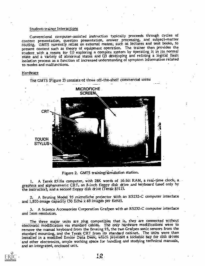
The GMTS (Figure 2) consists of three off-the-shelf commercial units:
CRT
TOUCH- STYLUS
MICROFICHESCREEN\
Figure 2. GiviTS trainingisiMulation station.
1. A Terak 8510a computer, with 28K words of 16-bit RAM, a real-time clock, a.graphics and alphantitherit CRT, an 8-inch floppy disk drive and keyboard (used only bythe instructor), and a second floppy caSk drive (Terak 8512).
2. A Bruning Model 95 microfiche projector with an RS232-C computer interfaceand 1,8004mage capacity (30 fiche x 60 images per fiChe).
3. A Science Accessories Corporation Graf pen with an RS232-C computer interfaceand lmm resolution.
The three major units are _plug compatible; that is, they are connected withoutelectronic modification via standard cables. The only hardware modifications were toremove the manual keyboard from the Bruning 95, the two Grafpen sonic sensors from thestandard mounting, and the Terak CRT from its sUndard cabinet. The units were theninstalled in a modified Emcor Data Desk, which provided a lockable bay for disk drivesand other electronics, ample working space for handling and studying tedmical manuals,and an integrated, enclosed unit.
12

This configuration provided two displays: (1) the computer-driven CRT usedprimarily to interact with the student regarding instructional and tutorial matters and (2)
a rear-projected microfiche screen for representing the real equipment.
The Grafpen provides he means of input to the trainer, and all student actions aremade by touching the CRT screen, the microfiche screen, or the command menu with astylus whose position can be sensed by the computer to within Imm accuracy. The CRT
acts exclutiVely in an administrative, vice simulation, capacity. It displays statementsand questions to (1) identify a student at the start of a session,X2) allow the instructor todesignate the latest lecture completed, (3) initiate new problems, (4) execute replace-ments requested by the - student, (5) verify current test' equipment selections andconnections, and (b) handle termination of problems and sessions. The microfiche screen
acts exclusively to represent the real equipment.
At the initiation of a new problem, the CRT displays an operator's complaint, such as:
THE MALFUNCTION LIGHT IS ON,
which is similar to a failure report initiating a real repair effort. Simultaneously, themicrofiche screen _displays a "top level" diagram that exhibits all equipments andperipheral systems;--that the student can manipulate or examine. The student obtainscloser and closer. views of the equipment by touching the area of interest with theacoustic stylus. This incremental "zooming" normally involves one to tiree steps, which
result in a close view of a relatively small portion of the entire system. Whenever aclose=up image is shown, front-panel indicatort will appear identical to the ones on thereal equipment, given the mode of operation and failure condtion, if any.
The student changes switch settings by touching the panel, as shown in Figure 3.Whenever the student touches a new switch "setting or test point with the stylus, thecomputer commands the microfiche projector to retrieve and display the image thatreflects the action taken.
Student Touches
20 40I
30 /50
20_31 0
4010=-,
Original Image Nett Image
Figure 3. Setting switthes in GMTS.

0
The command menu, shown in Figure 4, allows the student to interact with theexecutive program.
Higher
Level
Replace
Test
Equipment
Interpret
TIE Reading
Redefine
Ref. Point
Problem
Solved
Stop
Problem
Renew
Image
Figure 4. Command menu.
The commands and their effects are as follows:
1. HIGHER LEVEL. Students touch HIGHER LEVEL if they want to see the nextless detailed picture in the system's hierarchical structure. This was the picture fromwhich the currently projected section of the system was selected.
2. REPLACE. Students touch REPLACE if they want to replace the section of thesystem currently displayed. Subequent indications will reflect the success of this action.
3. TEST EQUIPMENT. Students touch TEST EQUIPMENT if they want to performtest equipmerit reading(). The. CRT displays a list-of all test equipment defined, and thetest points to which they are currently connected or "" if not connected). Forexample, the following display shows that a multimeter is connected to test-point 314 oncard 1A1A2:
TEST EQUIPMENT:
*OSCILLOSCOPE
*MULTIMETER
CONNECTED TO:=1IAIA2 314
Touching the asterisk (*) next to the desired test equipment name in effect causesthe touch stylus to become the probe for that type of test equipment. Touching adisplayed test point produces the test - equipment reading on the microfiche screen and thetest point designation on the CRT.
4. INTERPRET TIE READING. Stu&nts touch this command if they want help indetermining whether the test equipment reading currently displayed on the microfichescreen is normal or abnormal. This support is unavailable in test mode, and its use isrecorded with the student'S performance dat&
5. REDEFINE REFERENCE POINT. Students touch this command if they want torepeat the calibration of the currently displayed image by touching a special symbol in thecorner of the image.
6. PROBLEM SOLVED. Stu&nts touch this command if they believe they haverestored the simulated equipment to normal operation. In practice mode, students areallowed to continue a problem that has not, in fact, been solved. In test mode, thiscommand terminates a problem;
7. STOP PROBLEM. This commands the trainer to abort the current problem.
8. RENEW IMAGE. Touching RENEW IMAGE causes the microfiche projector toreproject the current image in case of poor registration.
Software
System Software
The sytern software described in this section consisted of computer programswritten in U -SD Pascal. Particular advantages of developing programs in UCSD Pascalare listed below:
1. pascal is highly standarthzed, maximizing ease of augmenting and maintainingprograms.
2. Pascal was specifically developed for ease of program transportability (i.e.,implementation on other computers).
'3. The structured nature of the language tends to promote well organized programsthat are easier to develop and, document.
4. The UCSD Pascal operating_system offers a complete filing and editing facility,which is used extensively during data base entry.
Instractional.and Simulation_Software
The computer programs that control the (on-line) delivery of instruction andsimulation are of two type
1. Simulation programs that sense and interpret student actions, determine theeffects of those actions in the real equipment, and respond by alteringthe presentation ofthe equipment on the simulation screen. The major components of simulation control are
listed below:
a. Student action interpretationSensing and interpreting the significance ofan action by the student, as indicated by a touch-pen strike.
b. State evaluationDetermining the state of an equipment (including testequipment) from data describing a malfunction and the current mOde.
c. Selecting the appropriate microfiche &splay.
Pedagocalrograms that select problems, provide symptom assessment assist-ance (INTERPRET TIE READING), record performance data, and offer other instructional
functions.
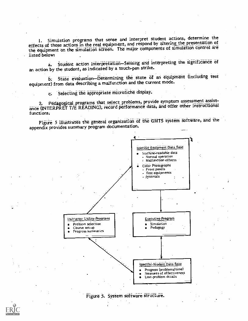
Figure 5 illustrates the general organization of the GMTS system software, and theappendix provides summary program documentation.
Instructor UtilitProgramsProblem selectionCourse set-upProgress summaries
Specific Equipment Data Base
Machine-readable data- Normal operation
.7- Malfunction effects
Color PhotographS- Front panels- TeSt equipments- ;internals .
Executive Program
SimulationPedagogy
Specific- Student Data Base
Progress (problems/time)Measures of effectivenessLast-problem details
Figure 5. System software structure.

Software for-Data Base Development
After organizing the alphanumeric data to describe the equipment, the SME keys thedata in at a keyboard that plugs into the computer. The resulting data file. maysubsequently be printed and edited, using system software provided with the system.
When this data file is prepared, a utility program is executed that reads in the sourcedata- converts it to a format that can be more rapidly accessed by the training program,and 'checks for a number of possible data errors. The resulting file is then copied todiskettes for use by students. If desired, the data be preparer may execute a secondutility program to verify the data base. This program operates on the data base exactlyas does the training program, except that it accepts keyboard input only and generatesCRT output only. Its purpose is to allow the data base preparer to run the simulator priorto producing the microfiche.
The third utility program used to support data base development is concerned withdefining the various points on each microfiche image. This program displays eachmicrofiche image, and the SME can cWsignate subpictures, test points, and switchpositions with the touch pen; As this is done, he identifies various points by touching keywords and numbers displayed on the CRT. At the completion of this process, a data file isautomatically produced to allow the trainer/simulator to interpret each student input.
Instructor Utility Programs
Instructor utility programs are provided to establish problem selection constraints,setup new classes, and produce class progress summaries. The special-purpose utilitiesa\ailable to instructors are as follows:
I. ADD STUDENTS.. This utility is used to prepare student cliskettes for newstudent data. It reserves space on each diskette for student data and heads that spacewith the new studerg's name.
2. GET STUDENT DATA. This utility, copies student performance data from eachstudent's diskette onto a class master diskette.
3. . PRINT STUDENT DATA. This utility prints out a record of each student'sperformance data in the class to date, providmg instructors with data on in&vidualstudent performance.
4. SET-PROBLEM SEQUENCE. This utility allows instructors to establish a newlyrequired sequence.of problems.
5. SEE PROBLEM SEQUENCE. This utility allows instructors to review theprescribed sequences of inclividual problems or problem tools.
Simulation Data Base
Preparation
The simulation consists of (1) the alphanumeric data base required to computeses_ponses of the equipment to _student actions and (2) color microfiche to simulate theappearance of real equipment. The alphanumeric data include the following:
1. Names of replaceable elements.111
-a-

2. Operator's failure complaint (to start each problem).
3; Names of test equipments available.
4. Names of test points (for verification on the CRT).
5. Lists of allowable test equipments for each test point.
6. Names of switches and settings;
7. Initial settings of each switch (by problem if desired);
8. Modes of operation.
9. Symptom-malfunction relationships by mode.
.10. Required equipment mode for replacement (usually cnergized).
11. Index to microfiche images.
In addition, a "map" of each section of the equipment is created by running the utilityprogram XY (tee appencaic). This map is a list of Cartesian coordinates that identifieseach active point (i.e., one which may be touched by the student with the input stylus).
With this rich base of textual and logical data, GMTS is able to do the following
1. Select an appropriate malfunction in accordance with the instructor's plan andthe student's progress.
2. Retrieve and &splay the operator's complaint to initiate the problem.
3. Project the "top level" diagram of the system.
4. -Display successively closer .views of the area of the real equipment indicated bythe student.
5. At the clote-up level where symptom information becomes visible, compute thesymptoms evident at each indicator in the currently vii wed section of equipment andproject the image containing these symptoms.
6. Respond to touch inputs it switch settings by recomputing all symptom data andprojecting the image reflecting both the switch setting change and the new symptoms, ifany.
7. Respond to requests for replacement by subsequently pr °clueing normal indica-tions, if the replacement was correct.
Respond to requests for symptom interpretation assistance if not in the testmode.
9. Record student performance data including errors and time.
While this data _b is necessarily complex and somewhat voluminous, an SME canlearn to &yelp!) such a file in 1 or 2 weeks. The only knowledge necessary is a thoroughunderstandmg of the equipment to be simulated.
g13
A complete guide has been prepared that describes the data files in detail, as well asthe process for developing them; This document will be published separately as a GMTSUser's Manual. The steps used in assembling the.information are described below:
1. Define scope of the training simulation (systemanalysis). The scope of thesimulation is determined by the modes in which that hardware is to be simulated. Themodes are defined in a listing of all prime equipment and test equipment, including anyperipheral equipment that will be either operated or observed by the student as hetroubleshoots;
2; - I I This step consists of determining the level towhich maintenance is performed (i.e., will modules; boards; or components be replaced?);defining the prerequisite skills of entering students; defining, terminal training objectives;and; finally, selecting malfunctions for simulation that will best offer the practicenecessary to attain those objectives.
Careful consideration should be given to student skills_tecessary for troubleshootingand to the maintenance philosophy of the equipment. These impact the depth ofknowledge the student must possess to repair the equipment and the choice of effectivepractice problems; The two general types of problems are those 'selected for theirinstructional value in illustrating a function of the unit; and those selected as a result oftheir incidence in the fleet.
3. Define the equipment states to be simulated. The elements defined by Step 1form a first level of subdi4ision of the entire system or equipment. Each of theseelements must be further subdivided. Nearly any system can be viewed as consisting of nomore than six to ten elements; Furthermore; even large; complex; multi-equipmentsystems rarely require more than three to four levels of division to reach meaningfulgroupings of dais; incacators; or test points; This means that the user will normally beable to access an area of current interest with only one or two changes of level; eachaccomplished by touching the stylus to the area of interest on the projected image;
_
Within each area of interest; the data base preparer must decide how many discretepositions of continuous controls and continuous indicators (such as meters) will besimulated; Generally ;- -three to five positions are adequate. At this step; the data baSepreparer enumerates the number of images required to represent the modes of operation .defined in step one; lithe number is excessive (over 1;800 using current micrographicshardware), one must either reduce the number of modes to be simulated or divide theequipment into smaller sections.
4. Photograph the real equipment in each state and produce color microfiche. Twotypes of pictures are required to support the simulation: (a) pictures of equipments orportions of equipments, which serve -as pathways to more detailed subpictures, and (b)pictures of all the states defined for sections with controls and/or indicators. The former,termed intermediate scenes; are Often produced- via a combination of photographs andgraphics art. The latter; -termed multistate scenes; are photographed using a detailedpicture list as a guide. The picture list defines each possible state (both normal andabnormal) of each multistate scene in terms of the control positions and indicationsrequired. Color, 35mm slides are then taken of each equipment state and sent in forcommercial microfiche production.
5. Encode the list of states, index to microfiche irna 1 and symptomatic functiondata In genera4 each simulated problem must deal with a) equipment malfunctioningdue to a fault,_ and (b) equipment now functioning properly; since the student has replacedthe faulty element.
1014
The data base preparer first collects the data required. to S.mulate the normaloperating equipment. For each section of the system, the normal pictures are noted andthe switch settings required to produce each picture are listed. Next, the data _basepreparer specifies the effects of each malfunction by identifying the sections of thesystem, including test equipment, that are affected by the malfunction;
The amount of data listed is greatly limited since (a) only exceptions to normality areidentified and (b) for any one section, many MalfUnctions will cause identical abnormalsymptoms. This commonality is exploited to minimize the data required to characterizethe effectS of a malfunction.
In addition to the data described above, the preparer also inputs such information asinitial switch settings and test point constraints (i.e., what test equipment can be used onvarious test points ?).
6. Key in the the resulting file. The information compiled in Step 5is keyed in at a trainer station and recorded on a diskette. Then a program is executedthat examines the data, checks for omissions and contracfictions, and reformats the datain machine-readable format. After any noted errors are corrected, a second utilityprogram is executed to identify the locations of all points that the user may touch withthe touch pen. This is accomplished by touching each "active" point in the picture andthen providing the associated subscene number, switch number, setting number, or testpoint number.
The data base structure is flexible, and it may be desired to carry the fidelity anddetail much further in some areas than others. Also, there are often many opportunitiesfor greatly paring the number of system states simply by eliminating redundant modes,bands, etc. Such reduction can often be done without artificially simplifying thetroubleshooting task. For example, if a transmitter' operates in 32 bands, the simulationmay only need to implement two or three.
Organization_and_Structure
A functional representatiOn of the graphic portion of the simulation data base ispresented in Figure 6. While this figure happens to represent a system with three levels,there may be up to ten levels of hierarchy employed. The system software does notrequire-a- uniform decomposition of subelements. Thus, some equipments in a system mayrequire four or five levels and, others, only one or two. Finally, the system softwareimposes- no constraints on the contents or layout of each Thus, most rapidresponse can be achieved by grouping together all images for a particular equipmentsection.
The alphanumeric data base is written to a single 8-inch cliskette, along with a copyof the system software. 'Thus, the trainer can be changed to simulate a differentequipment by changing the microfiche cassette and the data base thskette.

. 5
. Figure 6. Hierarchical system representation
AN/VISO-3 Simulation
The AN/V/SC=3 is a- transceiver that is the major component of a fleet satellitecommunication (SATCOMM) system. The SATCOMM system include, beside the
' ANINVSC=3, two antennas, amplifiers, relays, a teletype, and several minor components.The simulation data base was developed for the entire system, and the largest part of itrelated' the AN/WSC-3 itself.
Advancedskils training for the maintenance of the SATCOMM system is provided bythe Advanced onic Schools Division (AESD) of Service School Command, San Diego.This school was the esti:ea-1o? developing the data.base arid for gathering data on thesupportability of the GMTS. Six advanced development GMTS units were cOnstnicted,four of which were installed in the AESD scho-ol for data-base development and forexperimental, use by studentstudéntsThe results of these two efforts will be the subject of afuture report.
OperatigChaacteristics
GMTS resix)riw time to touch inputs varies according to touch location. Response totouching the CRT or command menu occurs within 0.1 second. The trainer responds byaltering the CRT display, updating the simulation display, or, if the touch was notidentifiable, emitting an audible beep.
16
Responses to inputs on the microfiche screen involve a compute delay plus imagechange time; The compute delay, which varies from one data base to another, rangesfrom less than 0;001 second -;:o approximately 5 seconds, with an average of approximately1 second. Image change time varies from approximately 1 second, if the new image is onthe same fiche as the current image, to approximately 3 seconds, if a fiche change isrequired.
Calibration
Although the touch pen inputs are detected to 1mm precision, the student is requiredonly to touch the pen Within a reasonable proximity to the desired point. GMTS interpretstouch inputs by comparing thd detectedtouch location to a set of defined, stored points.This process, however, requires a means for correcting for the following random hardwarevariations:
1. Variation in location of the CRT, touch-pen sensors, and command menu (fromone training unit to the next).
''I-tto=day variation of display location on the CRT.
3. Day-to-day variation in touchq)en operation.
These variations are measured each time a unit is energized. The calibration consistsof touching displayed targets on the CRT and command menu, thereby identifying theirexact location; This also verifies that the touch-pen and CRT are functioning correctly.
A more bothersome variation is the positional error in projecting microfiche images.As a result of the high magnification employed (22X); very small mechanical deviationsresult in errors as large as 0.5 inches 'in absolute position of an image on the screen.Normally, thit error would not cause difficulty; however, some images may contain testpoints or switch settings that appear less than 1 inch apart and could be confounded. Toovercome this variation, each Microfiche image contains a small "bulls-eye," called areference dot, in the lower right-hand corner. Each time a new image is displayed, theuser first touches the reference dot. The GMTS then corrects all subsequent user inputson that image by the calculated error offsets in the horizontal and vertical dimensions. Ifmicrographics projectors now under development can deliver_repeatable image positionwith errors less than 1116 inch, there will be no need for the reference dot.
The error correcting_ performed by the executive program allows the positional datastored on &skette to be independent of the particular unit that will employ it.Furthermore, it allows free- substitution of subsystems (touch pen, microfiche projector,CRT) without upsetting the reliability with which user inputs are interpreted.
RESULTS
Operational Effectiveness
The upgraded configuration of GMTS is smaller, lighter, and more economical thanthe laboratory model. While some aspects of user acceptance and training effectivenesscan be determined only after more dxtensive experience in the training setting, it appearsthat the system's response time, reliability, maintainability, and quality of simulation arevery satisfactory. Specific findings are listed below:
1722

1. The GMTS response time averaged -1 to 2 seconds. The worst cases, 5 to 8seconds, occurred in less than 5 percent of the system responses.
/ Student acceptance of the touch pen was highInputs are definite, as they areaccompanied by a faint click, and recognition by the GMTS was excellent.
3. Image quality on the microfiche screen was sensitive to the wear of the plastictithe holders covering each fiche. As the holders became scratched and opaque froniWear, the quality of the image deteriorated markedly. While the fiche itself is notaffected, the holders must be replaced periodically.
4. Given proper preventive maintenance attention, the microfiche retrieval systemfunctioned quietly and smoothly. On occasion, the unit either failed to retrieve andproject an image or projected a double image. On the average, thit occurred approxi=matety once for every 2 or :3 hours of use; When this happened, the student could touchRENEW. IMAGE at the command menu to correct the image projection: There was noinstance in whith an incorrect image was displayed.
Support Requirements
Table 1 presents projections of subSystem reliability and maintainability for theGMTS. The per unit failure rates, maintenance times, and repair costs are based upon 18months' experience with six units in a developmental environment and 4 months'experience with four units in a training setting.
Table I
System Reliability and Maintainability
Unit(Subsystem)
ProjectedFailuresPer Year
AverageMan-hoursPer Failure
PreventiveMaintenanceHours/Year
TotalMan -hoursPer Year
Projected PartsCosts ($)Per Year
Terack System 1 8 20 28 200
Graf pen 1 10 10 20 100
Bruning 95 10 I 50 60 200
Printer 1 10 14 50
System(Cables, etc.) 10 12 10
Total 134 560
Reliability of the computer, CRT, disk drives, and touch pen has been excellent; AsshoWn Table only two Lures per year . are projected for these components;Restoration times can average 8 to 10 hburs for these failures, assuming_ that malfpnc-=tiores will .most likely occur_ in the methanical 'portion of the disk drive or 'cynic beintermittent' Hard failures on circuit boards, however, could be corrected in lett than 2
18
!)A., to-

The most complex electren:echanical device in GNUS is the microfiche retrieval unit,which is projected to fail ten times per year. Restoration time is expected to begshort,however, as most failures are likely to involve jamming or slippage.
The 8-inch floppy diskettes have prover to be economical and reasonably durable.While extreme abuse will destroy the stored data, instructors can easily copy daily data tomaster diskettes and print hard-copy summaries. Thus, catastrophic tosses' of studentdata can be prevented;
Software Transportability
The. executive and utility programs were fully reprogrammed in UCSD, Pascal. Nosystem function required assembly language patches or nonstandard application of the-langtrge. These source programs have been compiled under the 1.3, 11.0, and 11,1 versionsof the Pascal compiler for the.Terak 8510a, the Apple 11, and the Altos ASC8000. SinceUCSD Pascal can be implemented by an increasing number of microcomputers, GMTSsoftware can capitalize upon future hardware improvements; The only machine-dependent software employed was related to interfacing with the touch input system andthe .microfiche system.
Instructor Utilities
The repertoire of utility programs for instructor use was expanded to includeprograms to set up diskettes for-new students, to control problem presentation, and tocopy, accumulate, and print out student performance data. In adclition utility programswere produced for use during data base ckveloprrent. These programs check and reformatthe raw input data and provide a convenient means for identifying touch points on thegraphic images.
One course has been conducted to train SMEs in data base preparation... Thisexperience inclicated that SMEs can be trained in less than 2 weeks to prepare a new database and execute the associated utility p-ograms.
CcoNCLUSIONS
The GMTS hardware and sc-.2-tw-are have been refined and doeumented to meet theobjectives of this, phase of research. The trainer is ready for test and evaluation in aNavy schlool.
UCSD PasCal is a suitable language for GMTS programming, and such programs aretransportable to other computers.'
IiECOMMENDATIONS
The software products that are described in this report are potentially useful to theNavy beyond this research. The UCSD Pascal operating system and language should beused, along with the GMTS computer' prnrams, for the prototype electronic equipmentmaintenance training (EEMT) system (Device 11$106), which is being developed forinitial-skills training of electronic ttichnicians and electronic warfare operators. Whilethe data base that simulates the AN /WSC -3 was developed for advanced-skills training, itcould be modified for use by the EEMT project. Different malfunctions would# have to besimulated, but the normal operations data base could be used intact. The microfiche

photographs would have to be replaced with media that are compatible with Device.I IB106, which uses videodisc.
Numerous questions regarding_ the feasibility of various pedagogical approaches anddesign alternatives for general-purpose maintenance simulators remain to be addressed byfuture research:
l Trainng efferliveness. Before the training effectiveness of general-purposemaintenance trainees can be determined, the following pedagogical issues should beaddressed:
The amount of student control that is optimal in various situations.
b. The types of support and aiding that should be provided.
c. How effectively an intelligent trainer can adapt to particular student needs(beyond pace of training and problem selection).
Many of these pedagogical issues are entwined with design variables. For example,we need to know the relative advantages and disadvantages of a single display trainer andhow data base preparation cost is affected by computer-generated graphics.
2. Fidelity. Research should be conducted to determine the need for three-dimensional maintenance simulators, which are realistic physical simulations of the realequipment. At a middle point on the realism continuum are hybrid trainers, which offerhandt-on use of actual test equipment in association with 6flat-palter' or twockmensionalsimulation of the less universal real equipment. Such combinations may provide a veryattractive combination of cognitive exercise and procedural drill and practice.
3; Representation; The process of preparing data bases for GMTS should bestreamlined. Since much of that process is clerical, a computer-aided approach may yieldconsiderable savings.
4. Application. We should learn more about the domain of the GMTS approach.The only assumption made abbirt the inherent nature of the simulated equipment is that itcan exist in a number of discrete states. Experience with applying GMTS to three largeelectronic systems indicates that it Ise sufficiently general to accommodate nearly allelectric and electronic simulations: Those functions that do not strictly meet theassumptions can almost always be reduced or restricted in ways that impose minimalartificiality. For example a continuously-reading meter can be defined as indicating asmall number of values, such as 0, low, normal, high, and maximum;
One question that remains is the extent to which nonelectronic systems could beacctimmcidatet that is, whether automatic boilers, engines, antenna mounts, and helicop=ter control mechanisms could be represented adequately by thit finite -state model. Ifnot, what is the nature of the deviation, and could further generalizations resolve theproblems?
5. Job=performance_measure& At the heart of all these questions is the issue ofsensitivity of job performance to various training alternatives. As yet, no data areavailable that relate the effectiveness of simulation-based maintenance training to on-the-job performance.

REFERENCES
Rigney, J. W., Cremer, R. H., Towne, D. M., & Bond, N.A. Measurement_and_predictionof _cognitive_loadings in corrective maintenance tasks (Technical Report No. 52). LosAngeles University of Southern California, BehaviOral Technology Laboratories, April1967.
Rigney, J. W., & Towne, D. M. MATGEN;_a_technique__ for enerating symptom=malfunction, matrices for complex devices. Los Angeles: University of SouthernCalifornia, Behavioral Technology Laboratories, 1972.
Rigney, J. W., & Towne, D. M. Computer-aided perfurmance training for diagnostic andprocedural tasks. Journal of Educational Technology Systems, 1974, 2, 279-304.
Rigney, J. W., & Towne, D. M. Some concepts, devices, and procedures for improvingtechnical trab: Oto 11-111 / -I ce of maintenance (NAVTRAEQUIPCENTechnical Report 76-C-0023-1 Los Angeles: Univeisity of Southern California,Behavioral Technology Laboratories, August 1977.
Rigr:ey, J. W., Towne, D. M., .King, C. A., & Moran, P. J. Field evaluation of thegeneralized_maintenance trainer-simulator: I. Fleet communications system (TechnicalReport No. 89). Los Angeles University of Southern California, Behavioral TechnologyLaboratories, October 1978.
Rigney, J. W., Towne, D. M., Moran, P. J. & MishIer R. A. Field evaluation of theKeneralized maintenance trainwsimulatradar repeater (NPRDCTech. Rep. 80-30). San Diego: Navy Personnel Research and Development Center, July1980. (AD-A083 977)
Towne, D. M. ARMAN - A computer system for applying MTM (Methods TimeMeasurement), Proceedings, Conference of MTM Applications. Fairlawn, NJ: MTMAssociation for Standards-and Research, 1968.
Towne, D. M., & Mason, A. K. Toward synthetic methods analysis. Journal of IndustrialEngineering, 1967, 18, 52=56.
Wylie, C. D., & Bailey,_ G. V. Electronic equiPment maintenancetraining_system:PreliminaryAesign options (NPRDC Tech. Note 79;3)-. San Diego: Navy PersonnelResearch and Development Center, October 1978.
21

APPENDIX
SUMMARY COMPUTER PRCCRAM DOCUMENTATION
A-0

SUMMARY COMPUTER PROGRAM DOCUMENTATION
Name of Program: TRAINER
Purpose: This program drives a prototype comNter=based training system known asthe Generalized Maintenance Trainer Simulator (GMTS) or Rigney Trainer, a device thatis currently used to simulate electronic equipment maintenance. Simulation is achievedby displaying one of a number of photographs of the equipment with a microficheprojector; interface with the user occurs via the projector, a sonic pen, and the CRT. Adata base file contains a complete description of the equipment, simulated faults in theeqtiipment, and a listing of the photographs; thus making TRAINER independent of theequipment that it simulates.:
Hardwa_re_requirements: UCSD Pascal (TM) operating system version I.5, Bruningmodel 95 microfiche projector, Science Accessories Corporation Grafpen, and a Terak8510 computer and 8512 disk &ive. The source code has also been compiled underversions 11.0 and 11.1 of UCSD Pascal.
Documentation: Fully documented.
Comments: Four other programs related to the trainer system are available:
1. XYComputes coordinates of touch points on the trainer panel.
2. PREPROCESSProcesses the alphanumeric data base (entered using the Pascaleditor) into the format required by TRAINER.
3. UTILITY - General utility routines for disk initialization, etc.
4. DATACKData base checkout /verification program.
**********
Name of Program: XY
Purpose: This program is to be used in conjunction with the TRAINER program tocompute the coorclinats of legitimate sonic pen touch points on the front panel of the
,trainer simulator. New touch points may be defined or old point positions revised; theresults are stored in the file RTXYDATA.DATA for use by TRAINER.
Hardware_Requirements: Same as for TRAINER.
Documentation: Fully documented:
**********
Name_of_Program: PREPROCESS.
Pte: This program is to. be used in conjunction with the TRAINER program toprocess the alphanumeric data base. It processes a data base created using the Pascallong-text editor (L2) to create the file RTDATA.DATA, which is used by TRAINER.
Hardware Requirement= UCSD Pascal (TM) operating system.
Documentation: Fully documented.
**********
Name of Program: UTILITY
Purpose: This program isto be used in conjunction with the TRAINER program toprovide necessary utility- routines for GMTS. Such routines inclUde disk initialization,problem sequence selection, current sequence examination, student performance print-outs, and a master copy routine.
Hardware Requirements: UCSD Pasc.al (TM) operating system:
Documentation: Fully documented.
**********
Name-of_Program: DATACK
Purpose: This program is to be used in conjunction with the TRAINER program toverify the logical correctness of the deta base used in the GMTS. It directs to the screendata that TRAINER would ordinarily se.:Id to the microfiche projector and reads its inputfrom the keyboard rather than from a sonic pen. This allows a user who is familiar withthe data base to trace errors made in preparing the data.
Hardware Requirements: UCSD Pascal (TM) operating system, version 1.5, Terak8510 computer with an 8512 (risk drive, and a Science Accessories Corporation sonic
Grafpen:
Documentation: Fully documented.


![[Distillation] - Towers Malfunctions (Kister)](https://img.pdfslide.us/doc/110x75/55cf9d79550346d033adc79f/distillation-towers-malfunctions-kister.jpg)